RM COSTRUZIONI ELETTRONICHE Srl KL7505V HF power amplifier User Manual KL7505 Istruction Rev 1 1
RM COSTRUZIONI ELETTRONICHE Snc di Marchioni Davide e Daniele HF power amplifier KL7505 Istruction Rev 1 1
General Specifications
www.rmitaly.com info@rmitaly.com
GENERAL SPECIFICATIONS
POWER SUPPLY
Working voltage from 11V to 14V
Maximum current consumtion 30A
30A Safety Fuse
RF PERFORMANCE
Frequency range 28-30MHz
10 METERS BAND
Maximum Gain 15db
Maximum Pover IN 10W (Higher powers may permanently damage the device)
Maximum Pover OUT 240W
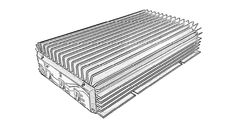
KL7505
USER MANUAL
ANT
RX\TX
12V
ANTENNA 50Ω
FREQUENCY RANGE EQUAL
TO OR GREATER OF 28-30MHz
10 METERS BAND
MAXIMUM POWER SUPPOR-
TED BY ANTENNA NOT LESS
THAN 240W
PAY ATTENTION TO THE
POWER POLARITY
RADIO
INSTALLATION NOTE
CONNECTION DIAGRAM
This device must be installed in an area where there is adequate ventilation for the heat
sink.
The amplifier is not designed for continuous transmission and should not be operated in
this manner. Failure to observe this will cause the amplifier to shut down from excessive
temperature.
If the amplifier is operated in high ambient temperatures transmission times should be kept
short to avoid excessive heat sink temperature. Excessive heat sink temperature will cause
the amplifier to shut down transmission. This is indicated when the TX LED flashes.
If this occurs operation of the amplifier should be stopped and the amplifier will regain
normal operation when the temperature falls to an acceptable level. This may take more
than 5 minutes.
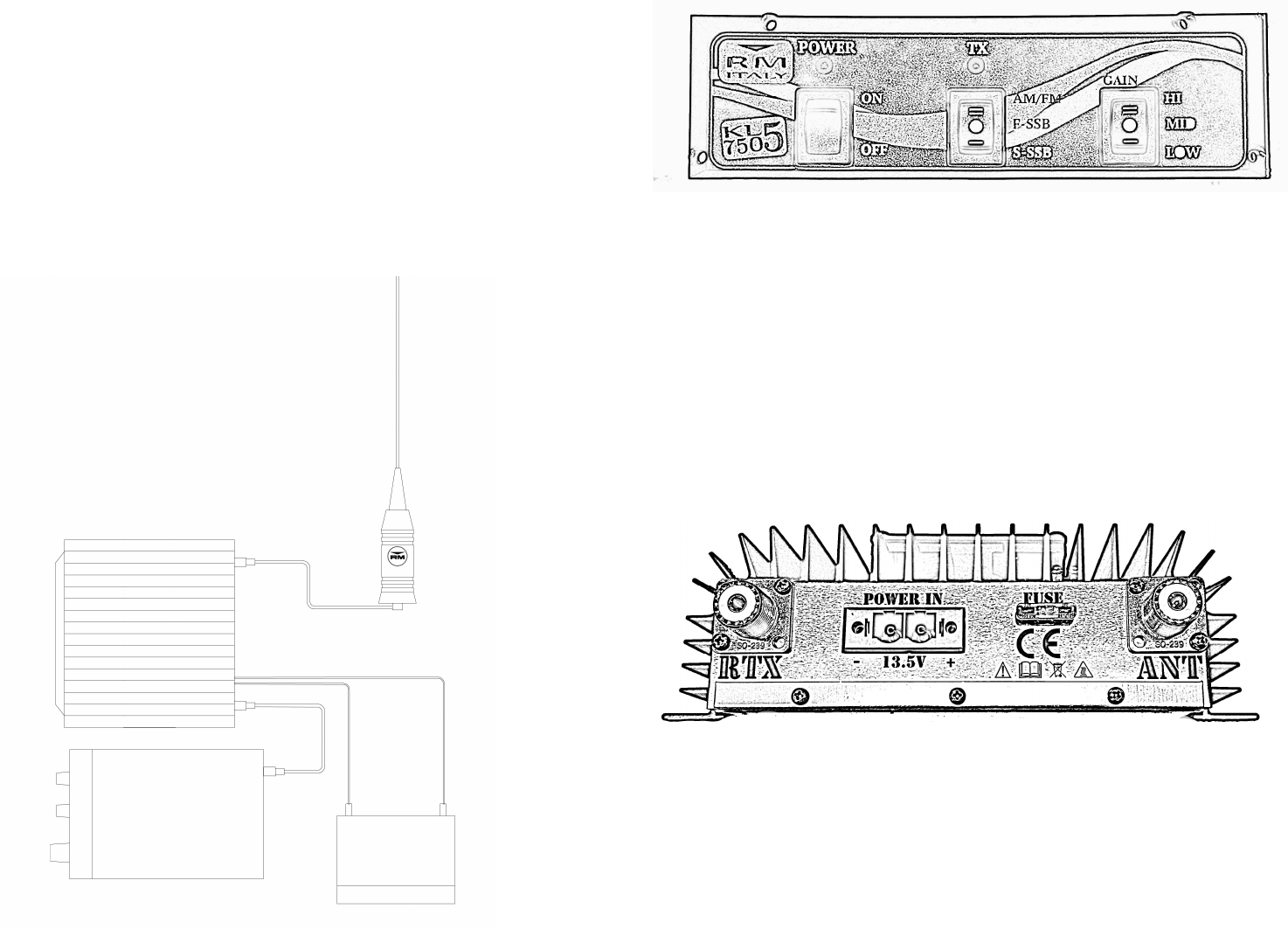
FRONT PANEL
BACK PANEL
[ \
^ _
[ Power On Led
\ Transmission state indication LED, if blinking indicates a
overtemperature. To restore turn off and turn on, again, the device.
] Power On switch
^ Modulation type selection (delay return to receive mode)
- AM/FM 0 Seconds Delay
- F-SSM 0.8 Seconds Delay
- S.SSB 1.2 Seconds Delay
_ Gain selection
- HI 14db ±1
- MID 12db ±1
- LOW 8db ±1
[ TX/TX 50Ω Connector to be connected to your radio transceive
MAXIMUM POWER-IN 10W
\ ANT 50Ω Connector to be connected to a proper antenna for the
frequency in use
] 13.5V Supply. Lower or unstable voltages compromise device
performance
]
\ ^
[ ]