RSI VIDEOTECHNOLOGIES BR50 Outdoor Badge Reader User Manual Installer Instruction
RSI VIDEOTECHNOLOGIES Outdoor Badge Reader Installer Instruction
UserManual.wiki
>
RSI VIDEOTECHNOLOGIES
>
BR50 User Manual
Installer Instruction
Navigation menu
Upload a User Manual
Namespaces
Wiki Guide
HTML
PDF
Info
Views
User Manual
Discussion / Help
Navigation

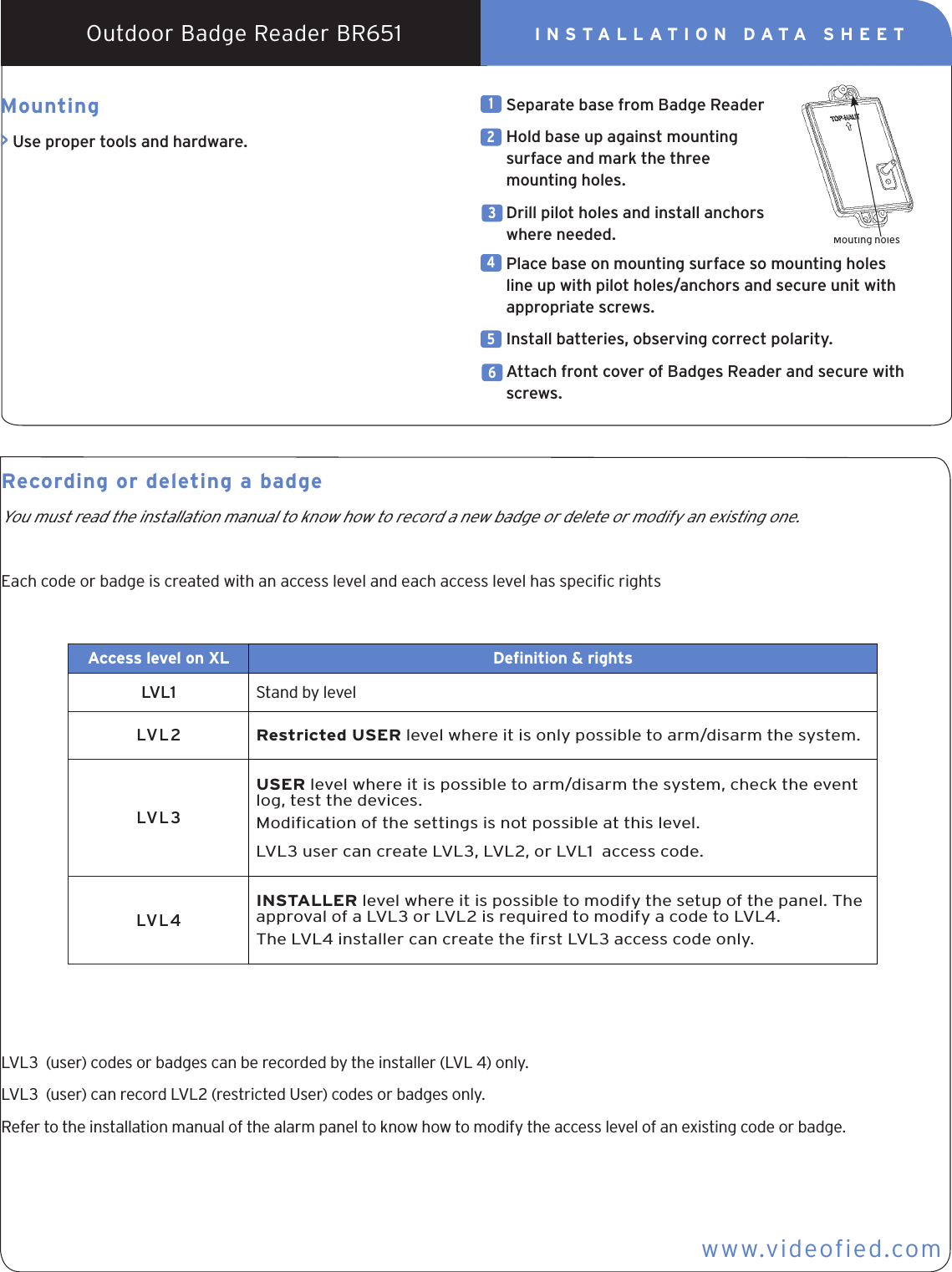
![Actions and commentariesRecording a new badgeWith the keypad, go to the menu :Display of the keypad Actions and commentariesBADGES ACCES CODESENTER ABADGE / CODEBADGE OR CODECODE NAME Enter the name of the code and Place your badge on the reader until you hear two beeps then after a few seconds the display will changeDelete a codeWith the keypad, go to the menu :Display of the keypadENTER ABADGE / CODEDELETINGBADGES / CODESDELETING CODEACCESS 5BADGE DELETED to accept the deletionThen repeat the operation for other badges or press on [ESC] for 5 seconds to return to the initial menu.Then to chose the concerned badge to select the badge.ACCESS 2ENTRY COMPLETE Waitwww.videofied.comINSTALLATION DATA SHEETOutdoor Badge Reader BR651](https://usermanual.wiki/RSI-VIDEOTECHNOLOGIES/BR50/User-Guide-1681274-Page-3.png)