RSI VIDEOTECHNOLOGIES BR50 Outdoor Badge Reader User Manual Installer Instruction
RSI VIDEOTECHNOLOGIES Outdoor Badge Reader Installer Instruction
Installer Instruction
Product Summary
The Outdoor Badge Reader BR651 is designed for use in
operating a Videofied security system. The Outdoor Badge
Reader includes the following features:
> Totally wireless, battery operated
> Dual tamper function provides detection for both wall and
cover tamper.
> Transmits check-in/status signal every 8 minutes.
> Mobility-Use outdoors or indoors with a fully weather
proof casing withstanding temperatures from -25°C to
+60°C.
> Depending the alarm panel used, up to 18 badges can be
recorded.
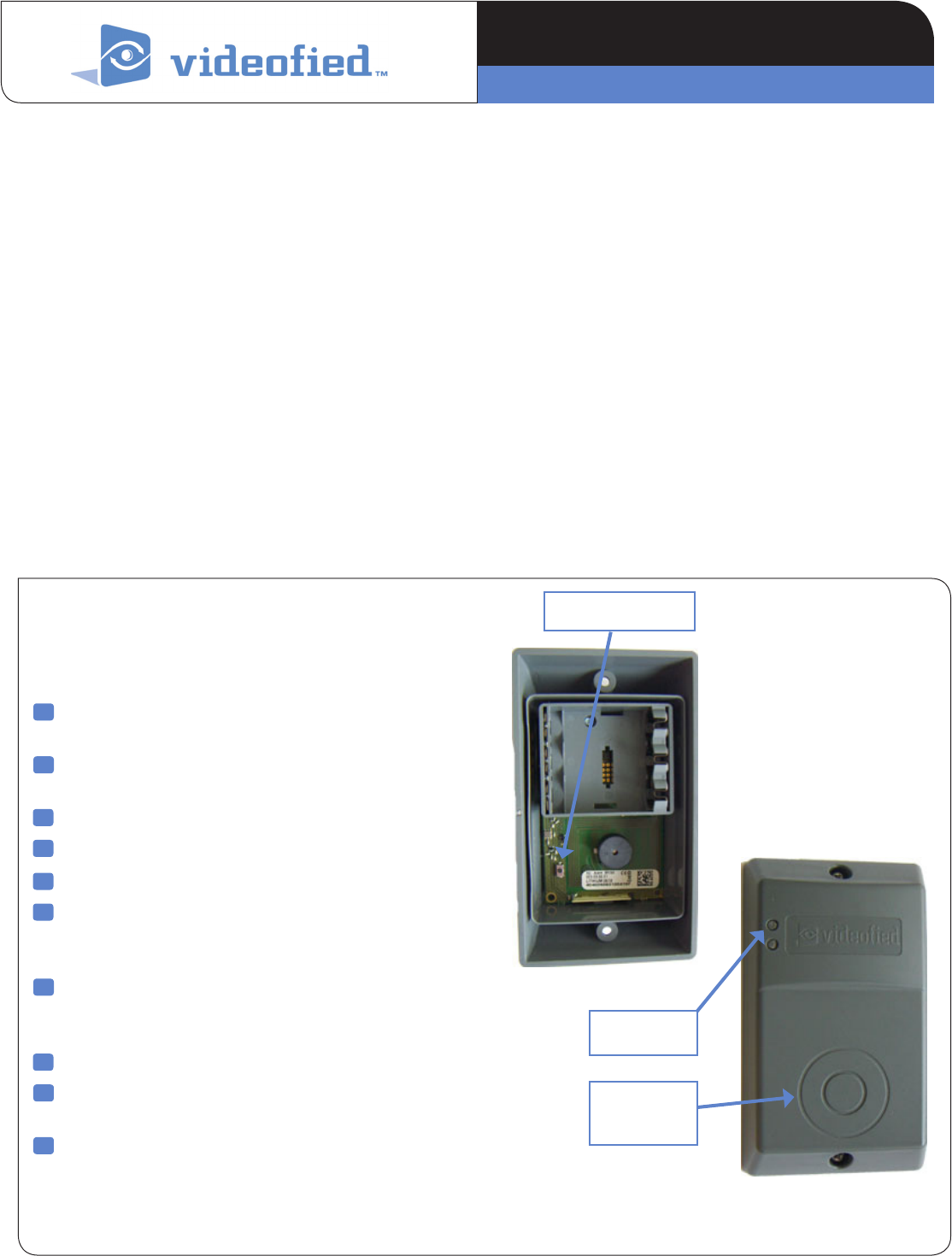
PROGRAM Button
Surface of the
badge reader
1
2
3
4
5
Indicator LED
Installation Guidelines
For easier installation and programming, RF testing should be
done to check for good communication between the control
panel and all system devices before mounting system devices.
Install the badge reader and other system devices in order of
the following steps:
> Programming/RF Testing - program reader and all other
devices into the control panel and test RF communication
from each intended device location to the control panel.
> Mounting - mount reader at the tested location.
Programming /RF Testing
The following provides summarized steps for device
programming and testing. For complete details, refer to the
control panel installation manual.
Remove top and bottom screw, separate base from Badge
Reader and install batteries.
Put control panel into configuration/add a new device
mode using the keypad.
Press the programming button on the inside of the case.
Wait for keypad display to show Badge Reader Recorded
Re-attach base to secure tamper switch.
Press Yes on the keypad. The display shows RADIO RANGE
TEST? Press Yes again. The detector LED starts flashing
and keypad display shows TEST IN PROGRESS.
Take badge reader to its intended mounting location
and make sure LED flashes continuously, indicating good
communication with control panel.
Press Yes to end radio range test, then press Esc/No.
The display shows RECORDING A NEW DEVICE? Repeat
steps 4 - 8 for remaining badge readers.
When finished, exit from configuration mode.
8
9
6
10
7
www.videofied.com
PRODUCT INSTALLATION SHEET
Badge Reader BR651
2208-BRIS March 2012Made by RSI VIDEO TECHNOLOGIES

Mounting
> Use proper tools and hardware.
Separate base from Badge Reader
Hold base up against mounting
surface and mark the three
mounting holes.
Drill pilot holes and install anchors
where needed.
Place base on mounting surface so mounting holes
line up with pilot holes/anchors and secure unit with
appropriate screws.
Install batteries, observing correct polarity.
Attach front cover of Badges Reader and secure with
screws.
3
1
2
5
6
4
Recording or deleting a badge
You must read the installation manual to know how to record a new badge or delete or modify an existing one.
Each code or badge is created with an access level and each access level has specific rights
LVL3 (user) codes or badges can be recorded by the installer (LVL 4) only.
LVL3 (user) can record LVL2 (restricted User) codes or badges only.
Refer to the installation manual of the alarm panel to know how to modify the access level of an existing code or badge.
Mouting holes
Access level on XL Definition & rights
LVL1 Stand by level
LVL2
Restricted USER level where it is only possible to arm/disarm the system.
LVL 3
USER level where it is possible to arm/disarm the system, check the event
log, test the devices.
Modification of the settings is not possible at this level.
LVL3 user can create LVL3, LVL2, or LVL1 access code.
LVL4
INSTALLER level where it is possible to modify the setup of the panel. The
approval of a LVL3 or LVL2 is required to modify a code to LVL4.
The LVL4 installer can create the first LVL3 access code only.
www.videofied.com
Outdoor Badge Reader BR651 INSTALLATION DATA SHEET
Actions and commentaries
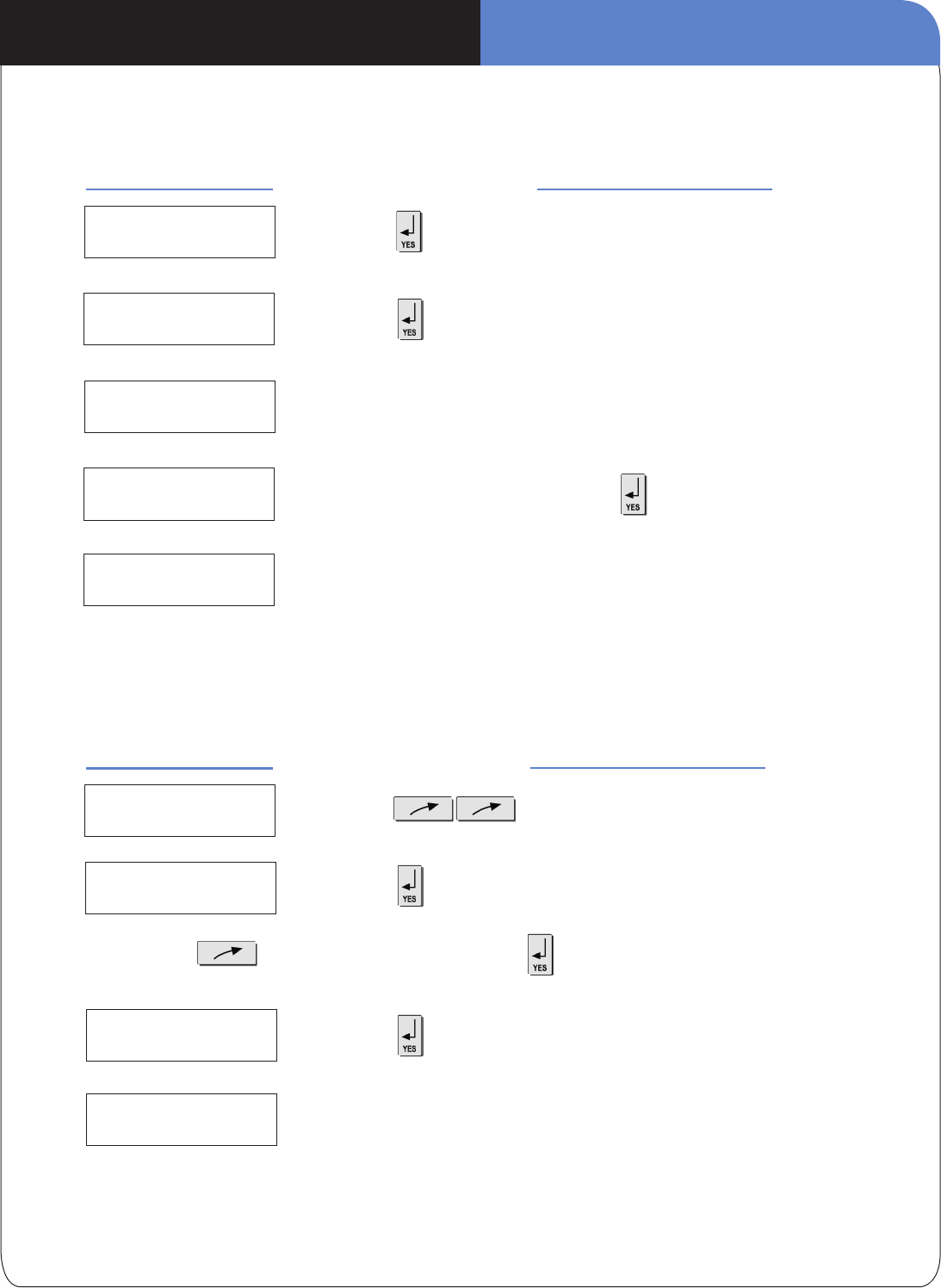
Recording a new badge
With the keypad, go to the menu :
Display of the keypad Actions and commentaries
BADGES
ACCES CODES
ENTER A
BADGE / CODE
BADGE OR CODE
CODE NAME Enter the name of the code and
Place your badge on the reader until you hear two beeps then after a few
seconds the display will change
Delete a code
With the keypad, go to the menu :
Display of the keypad
ENTER A
BADGE / CODE
DELETING
BADGES / CODES
DELETING CODE
ACCESS 5
BADGE DELETED
to accept the deletion
Then repeat the operation for other badges or press on [ESC] for 5 seconds to return to the
initial menu.
Then to chose the concerned badge to select the badge.
ACCESS 2
ENTRY COMPLETE Wait
www.videofied.com
INSTALLATION DATA SHEETOutdoor Badge Reader BR651
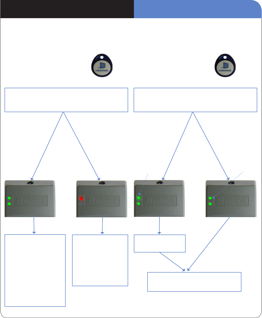
During arming
The arming stops.
The two indicators ash green
for 5s then turn off: A fault was
detected.
In order to know more about
what happened a keypad is
required.
Without action from the user,
arming will start again after 3
min and the concerned detector
will be bypassed from this
arming.
Flashing of the top red
indicator (only) every second
during arming delay.
The top red indicator
ashes every two seconds
indicating that the system is
armed.
Everything is ne :
System is arming
Problem was
identied during the
incomplete arming
(detection in and
instant area)
The LEDs will stay
on for 5 seconds
The indicators goes off, the system is disarmed.
There was no alarm
An alarm triggered
on
The top indicator
ashes green for
2s, and that of the
bottom ashes
xed green light
and the reader
beeps 4 times
The two
indicators
remain on with
xed green light
for 5 seconds
When reading the badge, the reader emits a beep, then two
beeps indicating the badge has been accepted. The LED
indicators of the reader are going to indicate a message:
When reading the badge, the reader emits a beep, then two
beeps indicating the badge has been accepted. The LED
indicators of the reader are going to indicate a message:
Functioning of indicators
The complete functioning of the indicators is only possible with the XL / XT / XV / VISIO v5.2 / V6000 V31.02 or superior control
panels.
During disarming
Verify with a keypad in
order to know more about
what happened
INSTALLATION DATA SHEETOutdoor Badge Reader BR651

Electrical Data
Panel Compatibility XL, Visio, XT, XTIP
Power requirements Three 3.6 V batteries
Nominal Voltage 3.6V
Low Battery Limit 2.7V
Battery type SAFT Lithium, LS14500
Battery life Up to 4 years
RF technology S2View®
Radio type Spread Spectrum Bidirectional
Operating frequency 915 MHz
Transmission security AES encryption algorithm
Supervision Polled signal every 8 minutes
Antenna Integrated
Tamper detection Wall and Cover tamper
Display lighting Automatic/ 2 LED
Built in sounder Emits arm and disarm beeps
Operating temperature -30°/+60°C (-20°/+140°F)
Maximum relative humidity 95%, non-condensing
Approvals FCC Part 15C
Physical Data
Material Polycarbonate UL94
Dim ensions 140 mm x 90 m m x 38 mm
(LxWxD): 5 1/2 in. x 3 1/2in. x 1 1/2
in.
Installation/Mounting
Unit/Base 2 screws secure the Badge Reader
to the base. 3 screws secure base to
flat mounting surface.
www.videofied.com
INSTALLATION DATA SHEETOutdoor Badge Reader BR651

EMEA SALES
23, avenue du Général Leclerc
92340 BOURG-LA-REINE
FRANCE
Hotline: +33 (0)820 846 620
Fax: +33 (0)1 82 69 80 10
© 2011 RSI VIDEO TECHNOLOGIES. VIDEOFIED® is a Registered Trademark of RSI VIDEO TECHNOLOGIES.
S2View® is a registered trademark of RSI VIDEO TECHNOLOGIES. Specications subject to change without notice.
USA SALES
4455 White Bear Parkway, Suite 700
White Bear Lake, MN 55110
USA
Hotline: +1 877 206 5800
Fax: +1 651 762 4693
www.videofied.com
FCC Regulatory Information for USA and CANADA
FCC Part 15.21 Changes or modifications made to this equipment not expressly approved by RSI VideoTechnologies may void the FCC
authorization to operate this equipment.
FCC Part 15.105 Class B
This equipment has been tested and found to comply with the limits for a Class B digital device, pursuant to Part 15 of the FCC Rules.
These limits are designed to provide reasonable protection against harmful interference in a residential installation. This equipment
generates, uses and can radiate radio frequency energy and, if not installed and used in accordance with the instructions, may
cause harmful interference to radio communications. However, there is no guarantee that interference will not occur in a particular
installation. If this equipment does cause harmful interference to radio or television reception, which can be determined by turning the
equipment off and on, the user is encouraged to try to correct the interference by one or more of the following measures:
• Reorient or relocate the receiving antenna.
• Increase the separation between the equipment and receiver.
• Connect the equipment into an outlet on a circuit different from that to which the receiver is connected.
• Consult the dealer or an experienced radio/TV technician for help.
Radio frequency radiation exposure information according 2.1091 / 2.1093 / OET bulletin 65
This equipment complies with FCC radiation exposure limits set forth for an uncontrolled environment. This equipment should be
installed and operated with minimum distance of 20 cm between the radiator and your body.
This transmitter must not be co-located or operating in conjunction with any other antenna or transmitter.
This device complies with Part 15 of the FCC Rules and with RSS-210 of Industry Canada.
Operation is subject to the following two conditions:
(1) This device may not cause harmful interference, and
(2) This device must accept any interference received, including interference that may cause undesired operation.
PRODUCT SPECIFICATION SHEETOutdoor Proximity Reader Model BR651