RSI VIDEOTECHNOLOGIES CM00 Keypad User Manual Installation Sheet
RSI VIDEOTECHNOLOGIES Keypad Installation Sheet
Installation Sheet
Product Summary
The Keypad CMA601 is designed for use in configuration/
programming and operating with a RSI Video Technologies
security system. The keypad includes the following features:
> Lithium batteries for long life.
> 2-line, 16-character alphanumeric LCD display
with backlighting.
> Armed status red LED.
> Built-in piezo for status and alarm sounds.
> Dual tamper function provides detection for both wall
and cover tamper.
> Transmits check-in/status signal every 8 minutes.
Installation Guidelines
For easier installation, programming and RF testing
should be done to check for good communication between
the control panel and all system devices before mounting
system devices. Install the keypad and other devices in the
order of the following steps:
> Programming/RF Testing - program keypad and
all other devices into the control panel and test
RF communication from each intended device
location to the control panel.
> Mounting - mount keypad at the tested location.
Programming/RF Testing
The following provides summarized steps for device
programming and testing. For complete details, refer to the
control panel installation manual.
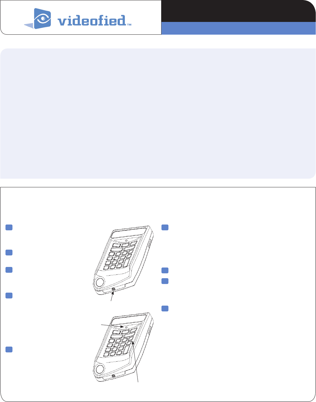
1 Remove bottom screw,
separate base from keypad
and install batteries.
2 Re-attach base to
secure tamper switch.
3 Put control panel
into programming/
configuration mode.
4 On keypad, press and
hold Clr and Esc/No
buttons together for
one second, then release
them. Wait for keypad
display to show KEYPAD
1 RECORDED.
5 Press Yes. The display
shows RADIO RANGE
TEST? Press Yes again.
The detector LED starts
flashing and keypad display
shows RF TEST #/9
6 Press Yes to end radio range test, then press Esc/No.
Note: If this is the first keypad programmed in a new installation,
the keypad display prompts you to enter other system configuration data.
If you are adding the keypad to an existing (operational) system, proceed
to step 9.
8 Repeat steps 1 - 8 for all alphanumeric keypads.
9 When finished, exit configuration mode.
Note: The control panel assigns alphanumeric keypads automatically
to Zone 1 (Entry/Exit Delay).
10 Refer to the users manual of your alarm panel to know how
use this device.
www.videofied.com
Screw
CLR and ESC/NO Buttons
LED
PRODUCT INSTALLATION SHEET
Keypad CMA601
Made by RSI VIDEO TECHNOLOGIES 2222-CMAIS March 2012
Mounting
> Use proper tools and hardware.
> Mount indoors in a temperature-controlled environment.
> Mount in a location that provides customer convenience,
but out of view from windows.
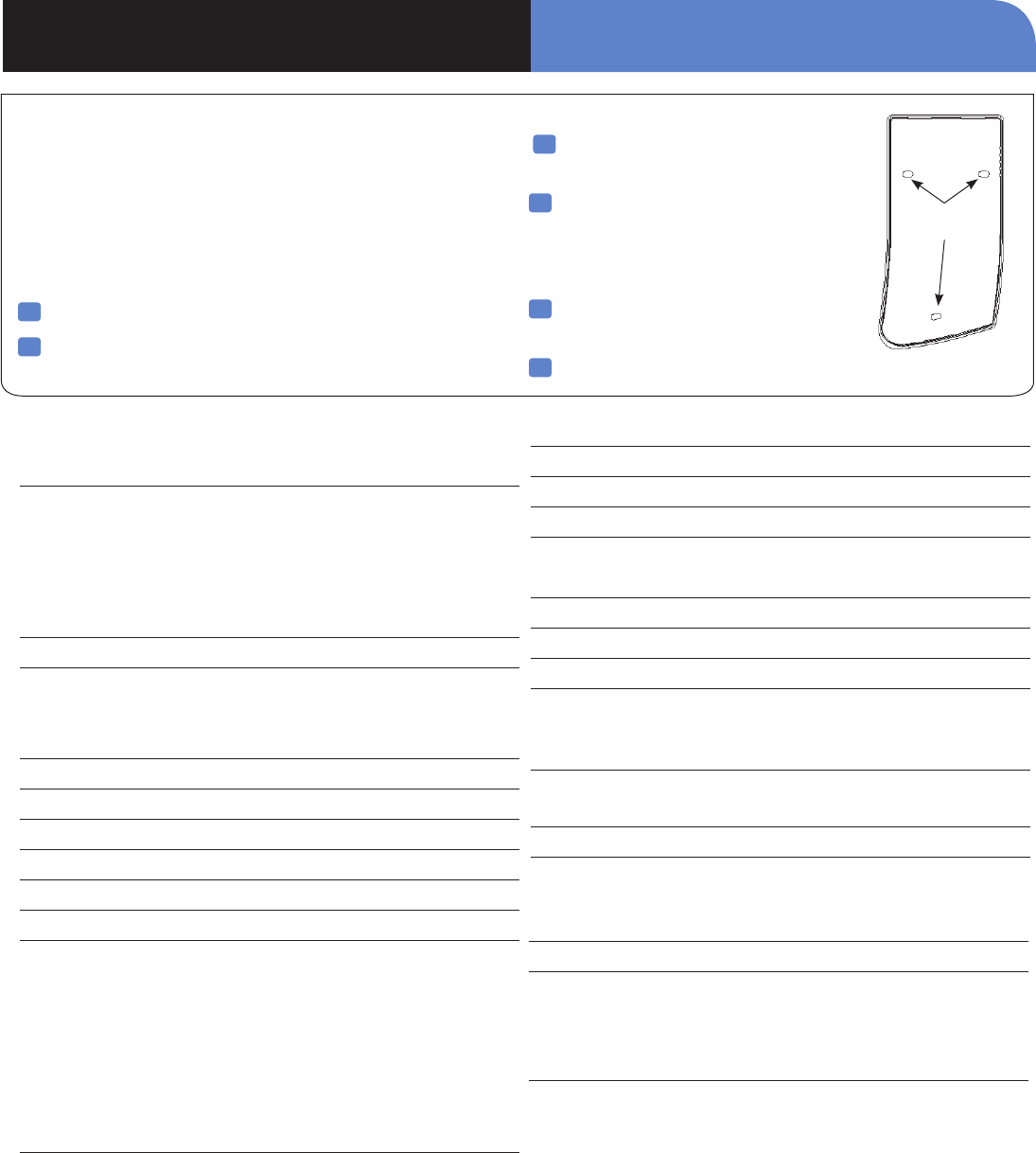
1 Separate base from keypad.
2 Hold base against mounting surface and mark the three
mounting holes.
3 Drill pilot holes and install
anchors where needed.
4 Place base on mounting surface
so mounting holes line up with pilot
holes/anchors and secure base with
appropriate screws.
5 Install batteries into keypad, observing
correct polarity.
6 Attach keypad to base and secure with screws.
Electrical Data
Panel Compatibility Videofied Alarm Panel XL,XT,XTIP, V6000
Power requirements:
Type: 3.6v SAFT Lithium, LS14500, AA Batteries Only
Nominal Voltage: 3.6v
Low Voltage Limit: 3v
Quantity 3x
Battery life (estimated) Up to 4 years
RF technology:
2 way S2View© RSI Technologies
915MHz frequency hopping
Radio type Spread Spectrum Bidirectional RF
Operating frequency 915 MHz
Transmission security AES algorithm encryption
Supervision Panel polls devices every 8 minutes
Antenna Integrated
Tamper detection Wall and cover tampered
Keypad:
Keys: 23x Keys
Allowed Time for Code Entry: 60s
Number of Illegal codes: 186 (depending on panel features)
User code input attempts before lockout: 5
Lockout duration: 90 seconds
Memory Lifetime: No Limit (Flash Memory)
Physical Data
Material ABS UL94-V0
Dimensions (LxWxD):6.3 x 3.6 x 1.2 Inches
(160 x 92 x 31 mm)
Weight 6.35oz (180gr) without batteries
Installation/Mounting
Wall Mount 3 Screws (including one for the tamper)
Case Lock 1 screw on bottom
Certification & Approvals
USA FCC Part 15C
UL 1023 (Applied For)
Assistance Request Police
Display type Liquid-crystal (LCD)
Display size Two lines, 16 characters each
Display backlighting Automatic
Built-in sounder:
Piezo Buzzer: Emits entry/exit delay beeps, alarms
Panic button One (Must be programmed/Enabled)
Operating temperature 14° - +104° F (-10° - +40° C)
Maximum relative humidity 75%, non-condensing
www.videofied.com
Mounting
Holes
Keypad CMA601 PRODUCT INSTALLATION SHEET

EMEA SALES
23, avenue du Général Leclerc
92340 BOURG-LA-REINE
FRANCE
Hotline: +33 (0)820 846 620
Fax: +33 (0)1 82 69 80 10
© 2011 RSI VIDEO TECHNOLOGIES. VIDEOFIED® is a Registered Trademark of RSI VIDEO TECHNOLOGIES.
S2View® is a registered trademark of RSI VIDEO TECHNOLOGIES. Specications subject to change without notice.
USA SALES
4455 White Bear Parkway, Suite 700
White Bear Lake, MN 55110
USA
Hotline: +1 877 206 5800
Fax: +1 651 762 4693
www.videofied.com
FCC Regulatory Information for USA and CANADA
FCC Part 15.21 Changes or modifications made to this equipment not expressly approved by RSI VideoTechnologies may void the FCC
authorization to operate this equipment.
FCC Part 15.105 Class B
This equipment has been tested and found to comply with the limits for a Class B digital device, pursuant to Part 15 of the FCC Rules.
These limits are designed to provide reasonable protection against harmful interference in a residential installation. This equipment
generates, uses and can radiate radio frequency energy and, if not installed and used in accordance with the instructions, may
cause harmful interference to radio communications. However, there is no guarantee that interference will not occur in a particular
installation. If this equipment does cause harmful interference to radio or television reception, which can be determined by turning the
equipment off and on, the user is encouraged to try to correct the interference by one or more of the following measures:
• Reorient or relocate the receiving antenna.
• Increase the separation between the equipment and receiver.
• Connect the equipment into an outlet on a circuit different from that to which the receiver is connected.
• Consult the dealer or an experienced radio/TV technician for help.
Radio frequency radiation exposure information according 2.1091 / 2.1093 / OET bulletin 65
This equipment complies with FCC radiation exposure limits set forth for an uncontrolled environment. This equipment should be
installed and operated with minimum distance of 20 cm between the radiator and your body.
This transmitter must not be co-located or operating in conjunction with any other antenna or transmitter.
This device complies with Part 15 of the FCC Rules and with RSS-210 of Industry Canada.
Operation is subject to the following two conditions:
(1) This device may not cause harmful interference, and
(2) This device must accept any interference received, including interference that may cause undesired operation.
Keypad CMA601 PRODUCT INSTALLATION SHEET