RSI VIDEOTECHNOLOGIES CT00 Door Contact User Manual Installalation sheet
RSI VIDEOTECHNOLOGIES Door Contact Installalation sheet
Installalation sheet
Product Summary
The Door Contact Models CT601 is a wireless door/window
contact designed for use with RSI VIDEO Technologies
security systems. The contact includes the following
features:
> Lithium battery for long life.
> External input for normally closed (NC) intrusion devices.
> Dual tamper function provides detection for both wall
and cover tamper.
> Transmits check-in/status signal every 8 minutes.
Programming/RF Testing
The following provides summarized steps for device
programming and testing. For complete details, refer
to the control panel installation manual.
1 Loosen bottom screw, separate base
from detector and install battery.
2 Re-attach base to secure tamper switch.
3 Put control panel into programming/
configuration mode.
4 Using a programmed alphanumeric
keypad, proceed through menus
until the display shows ADD A
NEW DEVICE.
5 Press Yes. The display shows
PRESS PROGRAM BUTTON OF DEVICE.
6 Press and release program button on detector using a
paper clip end. The detector LED flashes. Wait for keypad
display to show DETECTOR (1 - 25) RECORDED.
7 Press Yes. The display shows RADIO RANGE TEST?
Press Yes again. The detector LED starts flashing and
keypad display shows TEST IN PROGRESS.
8 Take detector to its intended mounting location and
make sure LED flashes continuously, indicating good
communication with control panel.
9 Press Yes to end radio range test, then press Esc/No.
10 The display shows AREA
ASSIGNMENT AREA: 1. Press
either arrow button repeatedly
until desired AREA number
appears, then press Yes.
11 The display shows PROTECT AN
EXTERNAL ACCESS? Press Yes or
Esc/No, whichever is appropriate
for this device.
12 The display shows NAME + LOCATION.
Enter appropriate device name/location (up to
16 characters), then press Yes. The display shows
the device number and name for your verification.
13 Press Yes. The display shows FUNCTIONAL DEVICE
TEST? Press Yes again and verify detector operation.
For example, move magnet next to detector to make
LED go out, then move magnet away from detector
to make LED turn on indicating detection.
14 Press Yes to end detection verification.
15 The display shows ENTERING A NEW DEVICE?
Repeat steps 1 - 14 for remaining detectors.
16 When finished, exit from configuration mode.
Installation Guidelines
For easier installation, programming and RF testing should
be done to check for good communication between the
control panel and all system devices before mounting
system devices. Install the detector and other system
devices in the following order:
> Programming/RF Testing - program detector and
all other devices into the control panel and test RF
communication from each intended device location
to the control panel.
> Mounting - mount detector at the tested location.
Remark: Only recorded contacts protecting the external access will be concerned by the Perimeter arming.
Use the keypad to activate Perimeter only arming. Press on (to activate the keypad), then shows on the
keypad enter a user code and validate with the key .
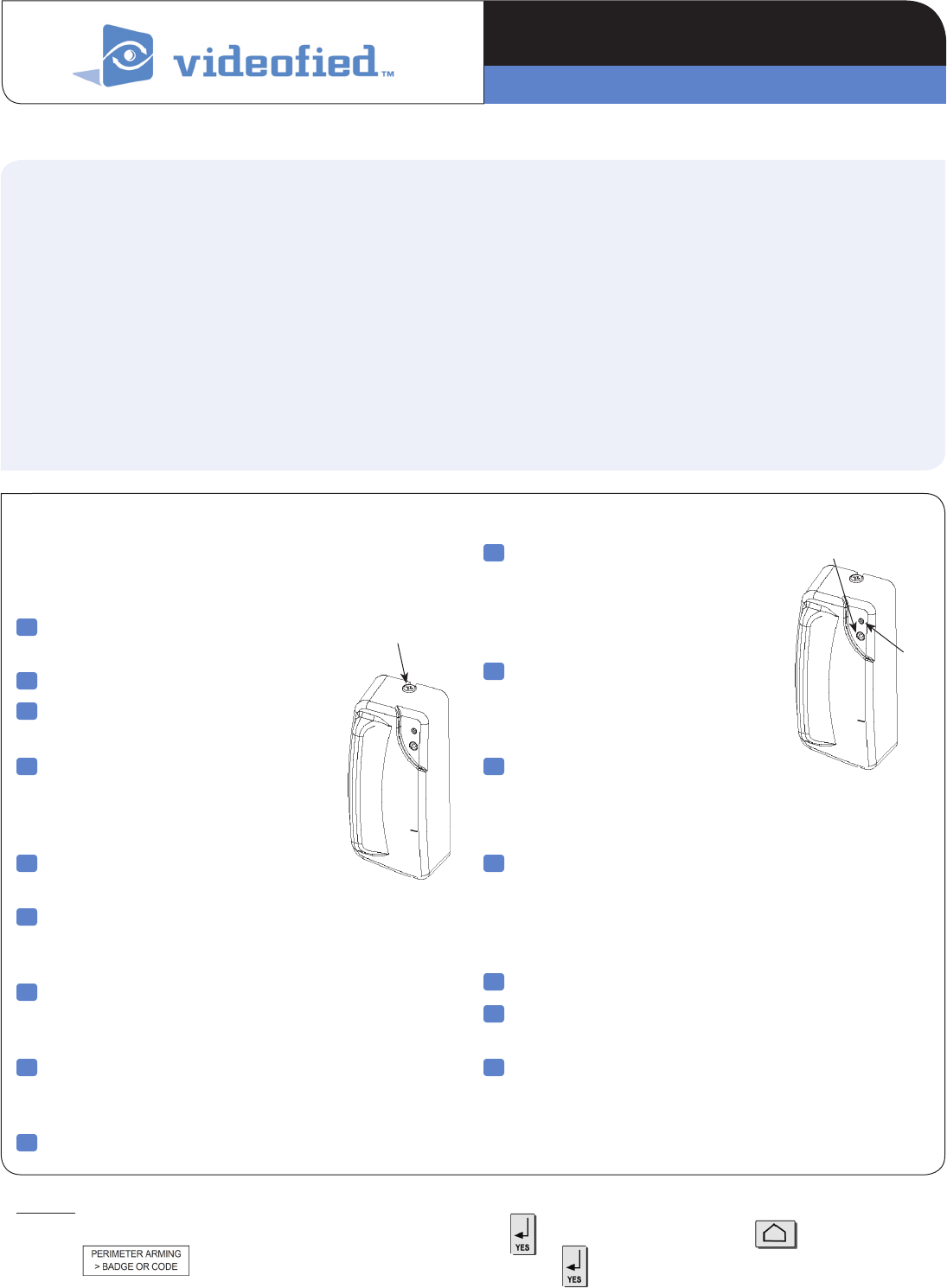
Screw
Program Button
LED
PRODUCT INSTALLATION SHEET
Door/Window Contact CT601
2209-CTIS March 2012Made by RSI VIDEO TECHNOLOGIES
Mounting
> Use proper tools and hardware.
> Mount indoors in a temperature-controlled environment.
> Mount detector on frame and magnet assembly on movable
opening (door, window).
> When using internal switch, mount so that detector and
magnet alignment marks are lined up with each other.
> When using internal switch, do not exceed 10 mm (3/8”)
gap between detector and magnet.
> Magnet spacers must be used to match magnet height with
detector to ensure correct alignment and functionality.
Note: If detector installation only requires use of the external input,
magnet assembly installation is not required.
1 Separate base from detector.
2 Hold detector base against
mounting surface and mark
the two mounting holes.
3 Drill pilot holes into mounting
surface.
4 Mount detector base to surface
using appropriate screws.
5 If using external input, run
2-conductor, 22-gauge wire from
protection point to detector.
6 Connect hardwire circuit wires to
external input screw terminals.
7 Connect other end of wires to
initiating device and install the
battery.
8 Attach detector to base, making
sure every wire is secure with screws.
9 Attach wedges to magnet holder
as needed to match height of detector.
10 Hold magnet base against
mounting surface and mark
the two mounting holes.
Note: Be sure alignment marks on detector
and magnet base are lined up with each other
and that there is no more than a 10 mm (3/8”)
gap between them.
11 Drill pilot holes into mounting surface.
12 Insert screws through magnet base and wedges,
then secure to mounting surface.
13 Attach cover to magnet holder.
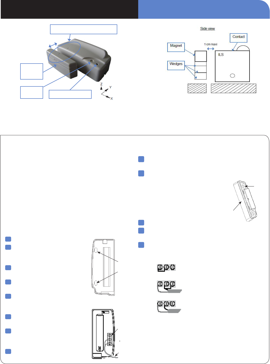
External Input Terminal, Jumper position and wiring
Note: The internal jumper wire is only used for internal or external
switch use. The jumper is not used when both Int. and Ext switches are
used together. The default jumper position is in the Internal switch mode.
it only has to be changed if wiring external switches to the transmitter.
The internal jumper shown in
position for possible connections.
1. Internal reed switch only
2. External reed switch only
3. Both Int. and Ext. switch use
> For the magnet to have proper detection, it must be positioned on the high part of the contact facing the ILS, use the supplied
wedges if needed. (see the diagram opposite).
> Magnet should always be positioned on the mobile part.
Three axis movement detection
Internal Reed Switch
External Reed Switch
Int + Ext Reed Switch
External
Input
Terminals
To
Initiating
Device
Mounting
Holes
Base
Wedge
Indicator
The markers must be lined up
Magnet +
wedges
PROGRAM Button
1 cm max.
PRODUCT INSTALLATION SHEETDoor Contact CT601

Electrical Data
Panel Compatibility Visio, XT, XL, XTIP
Power requirements
Type C
Nominal Voltage 3.6V
Low battery limit 2.7V
QTY and Battery Type One 3.6V Lithium battery
Battery type SAFT Lithium, LS14500
Battery life Up to 4 years
Current Consumption
Standby 30 uA
Max 70mA
Axis of detection Three axis (X, Y, Z)
Opening Detection Distance .9in (2.3cm)
Closing Detection Distance .8in (2.0cm)
RF technology S2View®
Radio type Spread Spectrum Bidirectional RF
Operating frequency 915 MHz
Transmission security AES algorithm encryption
Supervision Polled signal every 8 minutes
Antenna Integrated
Tamper detection Wall and cover tampered
External terminal input type Normally closed (NC)
Working modes 1-internal reed switch only
2-external input only
3-internal switch and external input
Mode selection Jumper wire on 3-position terminal block
Maximum external wire length 16 m/50 feet
Operating temperature -10°/+40°C (14°/104°F)
Maximum relative humidity 75%, non-condensing
Approvals FCC Part 15C
Physical Data
Material Plastic: ABS—ULV0
Magnet Alnico 5
Dimensions 80 mm x 35 mm x 23 mm
(LxWxD): Detector: 3 1/8 in. x 1 3/8 in. x 1 in.
Weight: Detector 40 g/1.4 oz. –without battery
Installation/Mounting
Detector One screw secures detector to base;
two screws secure detector to mounting surface.
Magnet Two screws secure magnet
assembly to mounting surface.
Spacing Maximum 10mm (3/8) in gap
between detector and magnet.
INSTALLATION DATA SHEETDoor Contact CT601

PRODUCT INSTALLATION SHEETDoor Contact Models CT601
EMEA SALES
23, avenue du Général Leclerc
92340 BOURG-LA-REINE
FRANCE
Hotline: +33 (0)820 846 620
Fax: +33 (0)1 82 69 80 10
© 2011 RSI VIDEO TECHNOLOGIES. VIDEOFIED® is a Registered Trademark of RSI VIDEO TECHNOLOGIES.
S2View® is a registered trademark of RSI VIDEO TECHNOLOGIES. Specications subject to change without notice.
USA SALES
4455 White Bear Parkway, Suite 700
White Bear Lake, MN 55110
USA
Hotline: +1 877 206 5800
Fax: +1 651 762 4693
FCC Regulatory Information for USA and CANADA
FCC Part 15.21 Changes or modifications made to this equipment not expressly approved by RSI VideoTechnologies may void the FCC
authorization to operate this equipment.
FCC Part 15.105 Class B
This equipment has been tested and found to comply with the limits for a Class B digital device, pursuant to Part 15 of the FCC Rules.
These limits are designed to provide reasonable protection against harmful interference in a residential installation. This equipment
generates, uses and can radiate radio frequency energy and, if not installed and used in accordance with the instructions, may
cause harmful interference to radio communications. However, there is no guarantee that interference will not occur in a particular
installation. If this equipment does cause harmful interference to radio or television reception, which can be determined by turning the
equipment off and on, the user is encouraged to try to correct the interference by one or more of the following measures:
• Reorient or relocate the receiving antenna.
• Increase the separation between the equipment and receiver.
• Connect the equipment into an outlet on a circuit different from that to which the receiver is connected.
• Consult the dealer or an experienced radio/TV technician for help.
Radio frequency radiation exposure information according 2.1091 / 2.1093 / OET bulletin 65
This equipment complies with FCC radiation exposure limits set forth for an uncontrolled environment. This equipment should be
installed and operated with minimum distance of 20 cm between the radiator and your body.
This transmitter must not be co-located or operating in conjunction with any other antenna or transmitter.
This device complies with Part 15 of the FCC Rules and with RSS-210 of Industry Canada.
Operation is subject to the following two conditions:
(1) This device may not cause harmful interference, and
(2) This device must accept any interference received, including interference that may cause undesired operation.