RSI VIDEOTECHNOLOGIES XT00 Control panel User Manual Installation Manual for XT XTX XTO series
RSI VIDEOTECHNOLOGIES Control panel Installation Manual for XT XTX XTO series
UserManual.wiki
>
RSI VIDEOTECHNOLOGIES
>
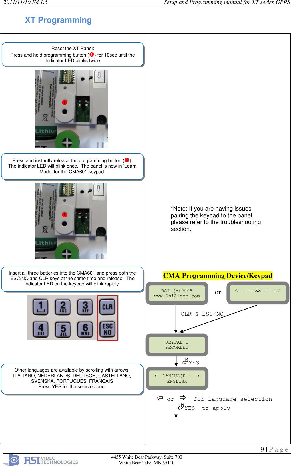
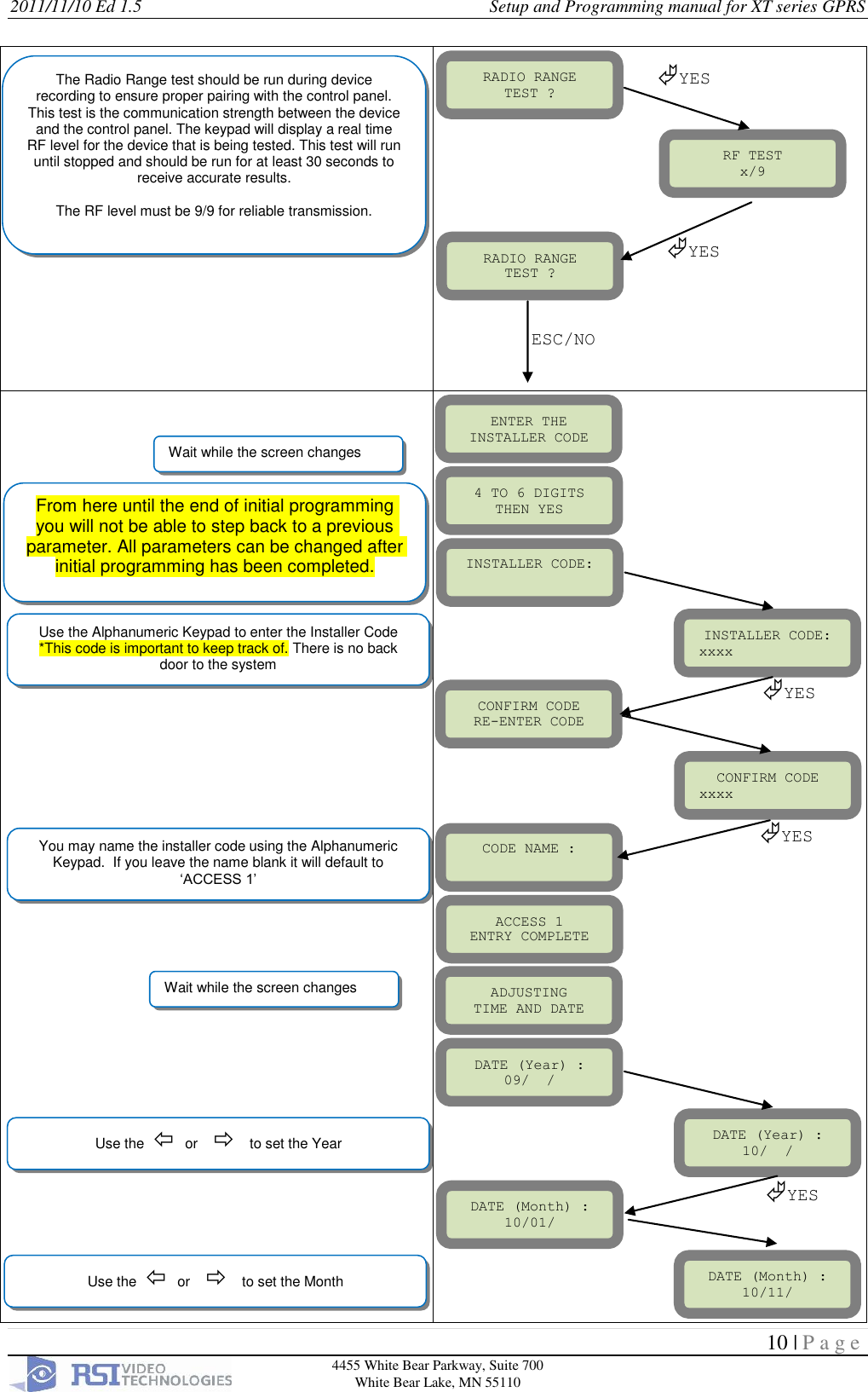
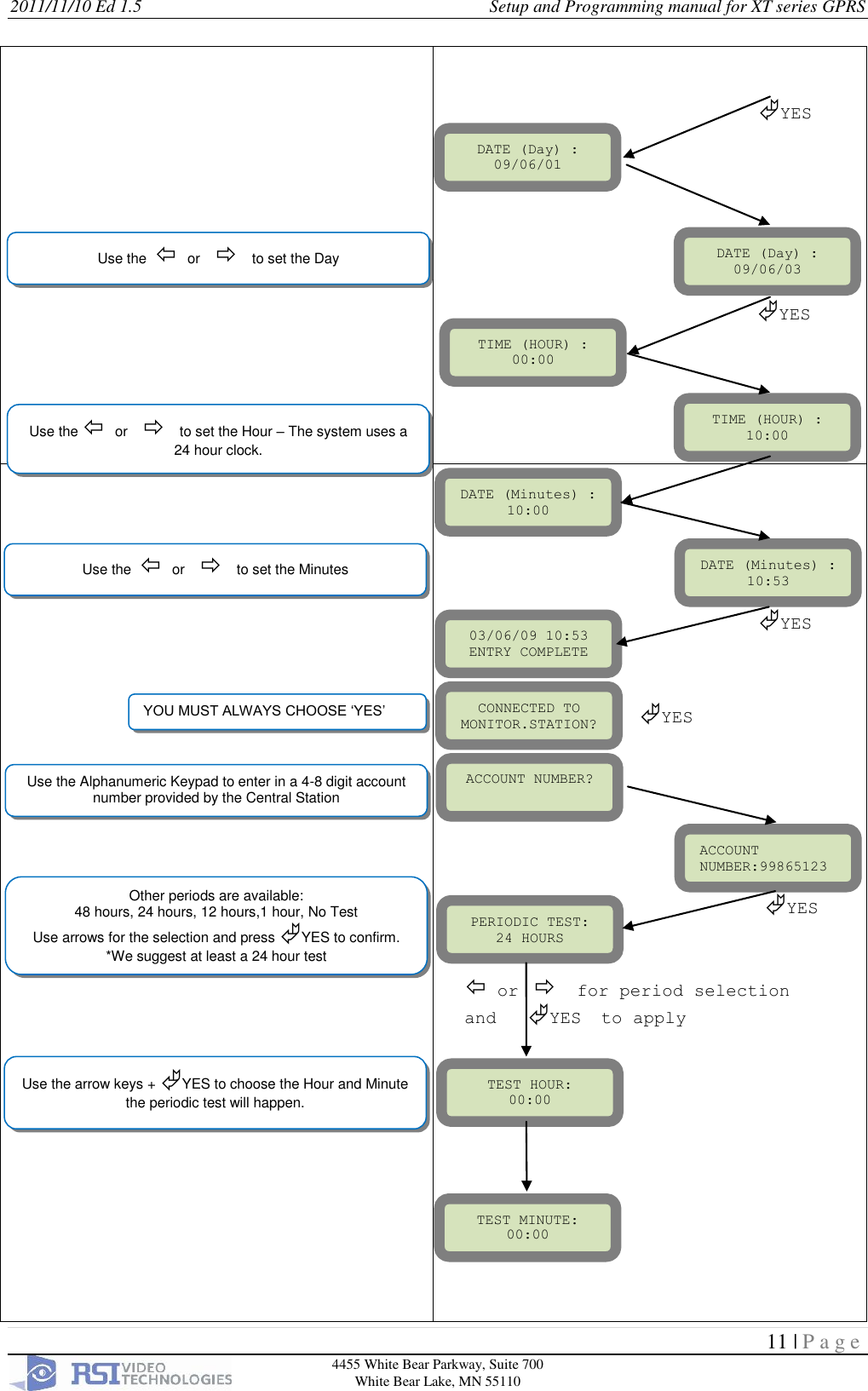
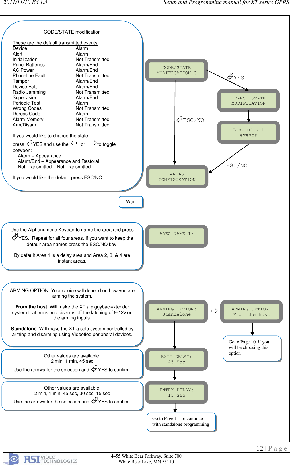
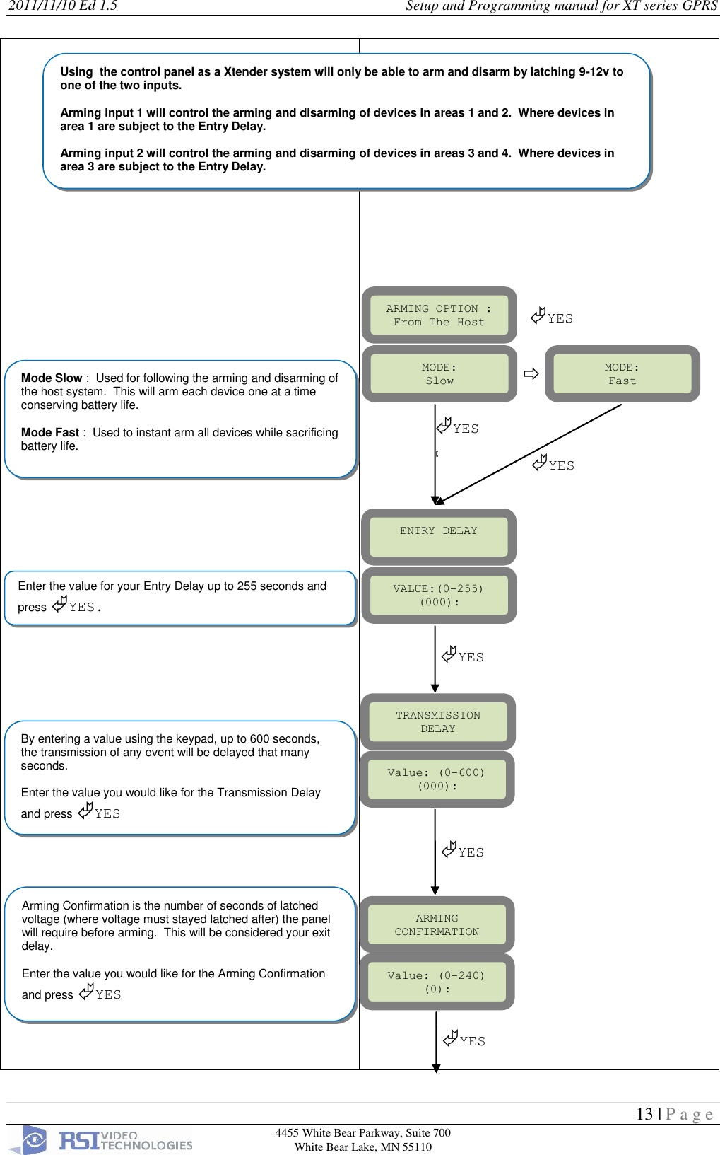
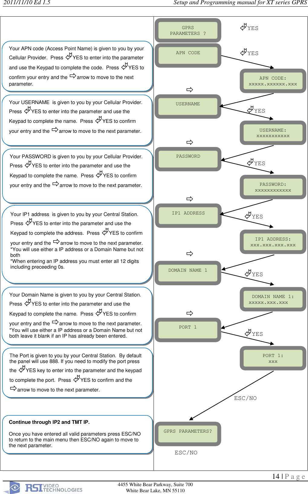
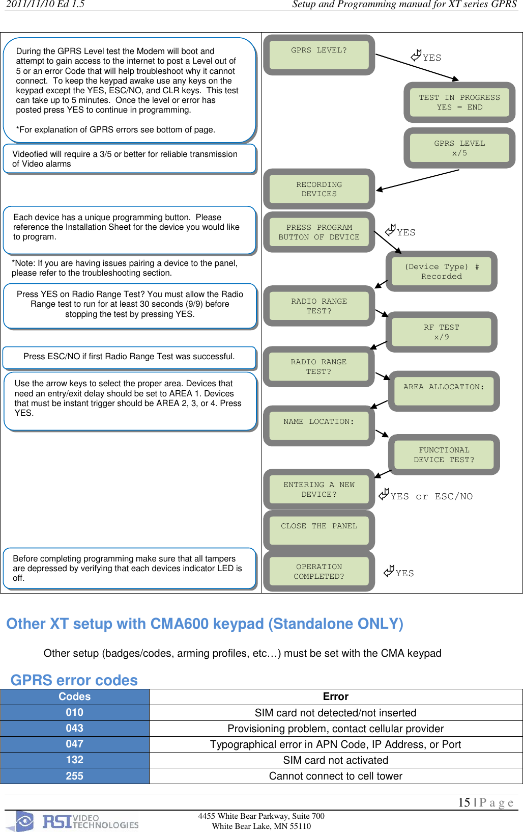
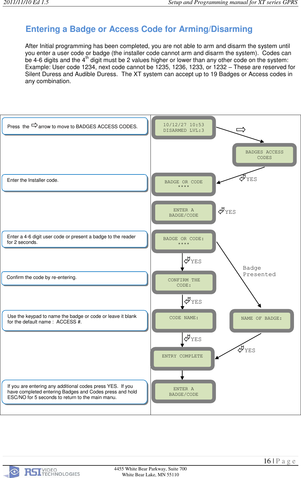
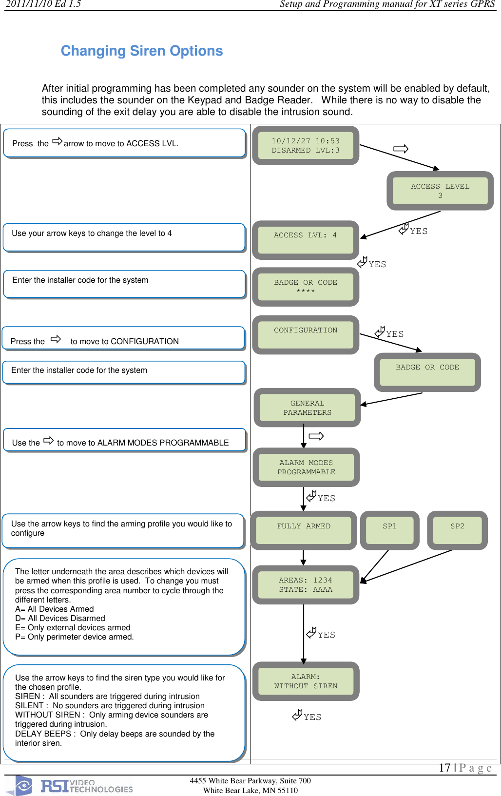
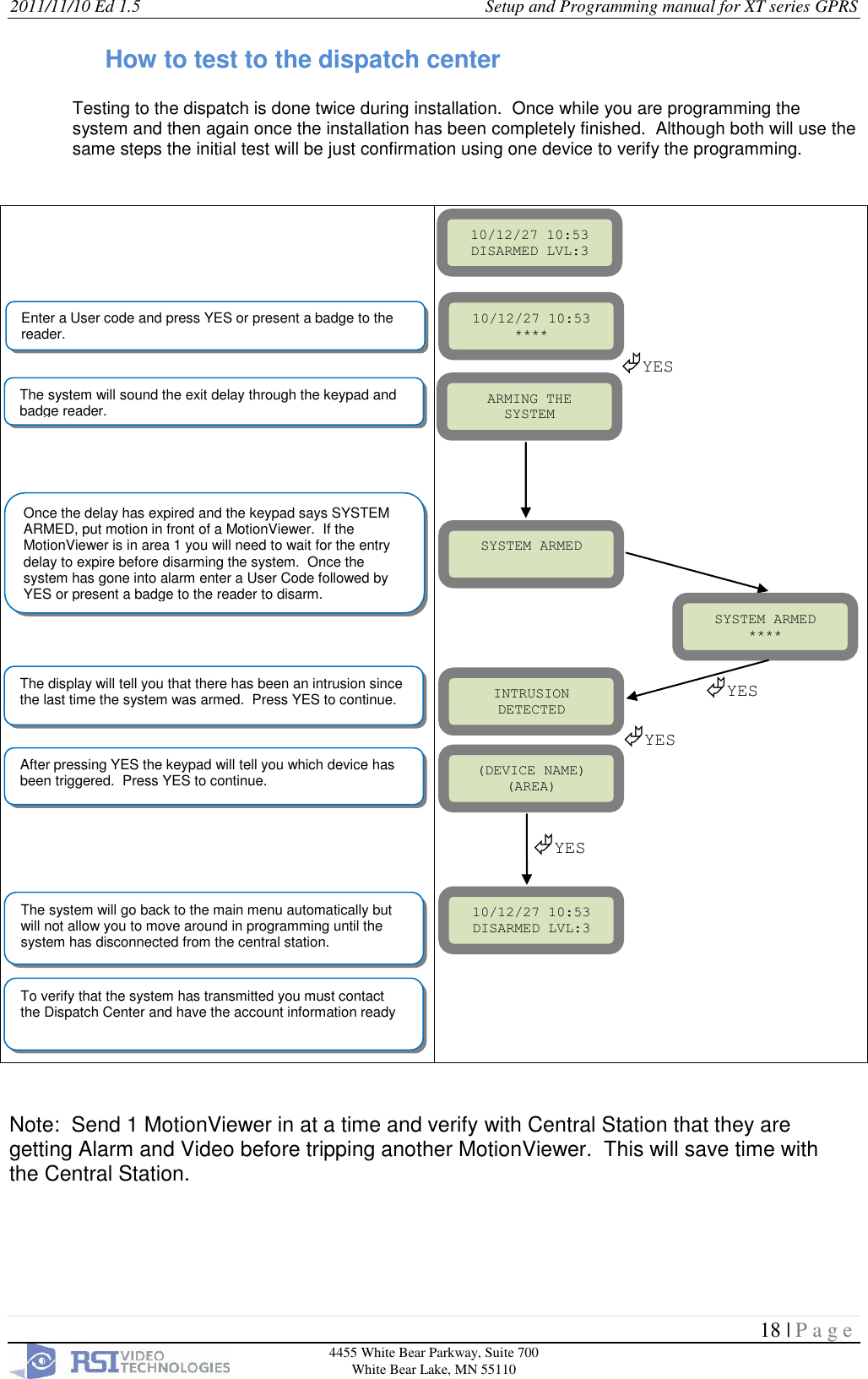
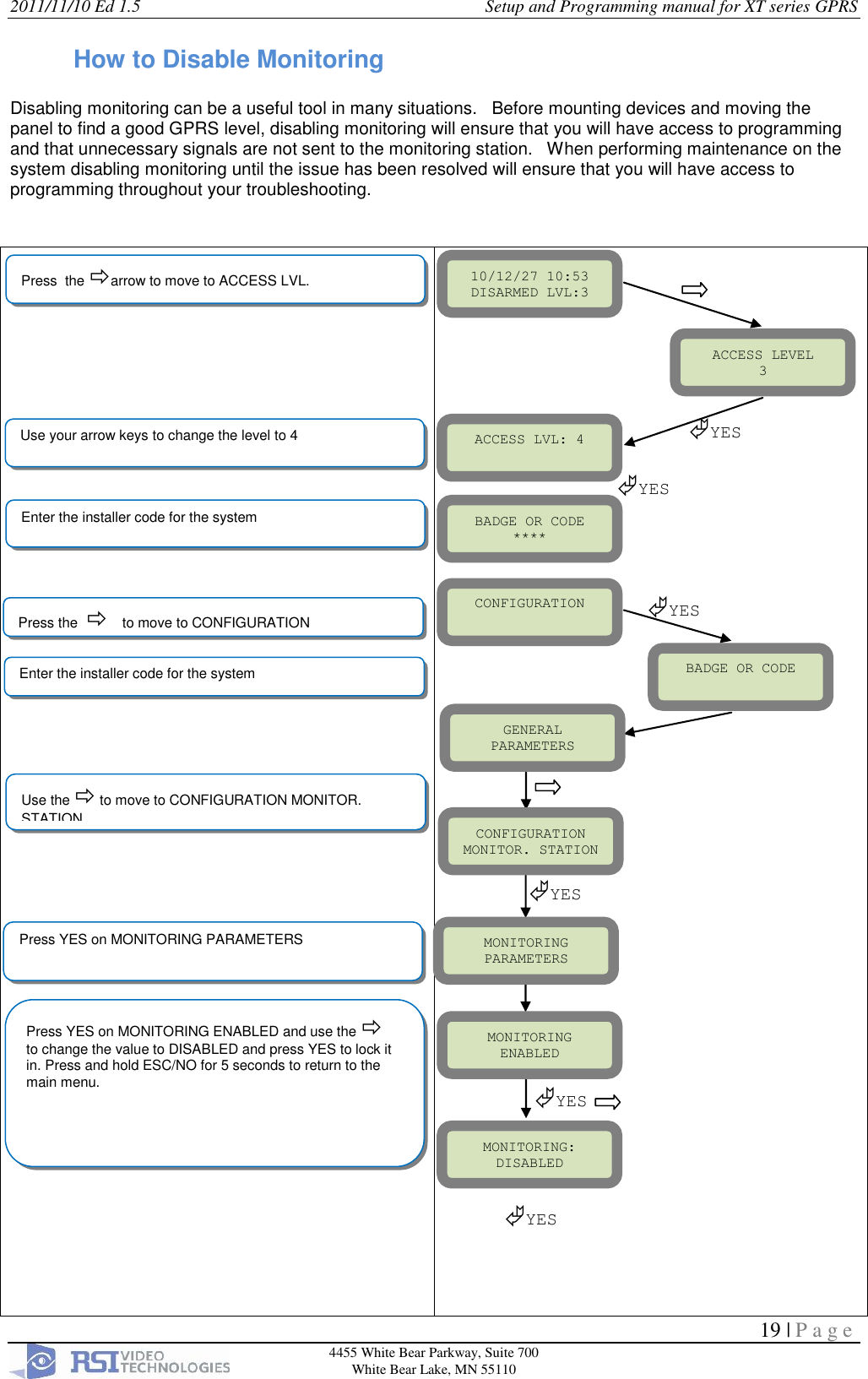
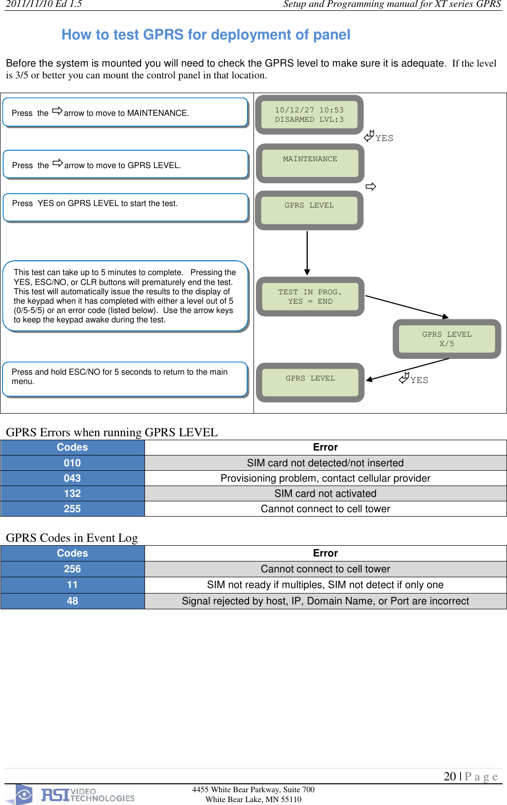
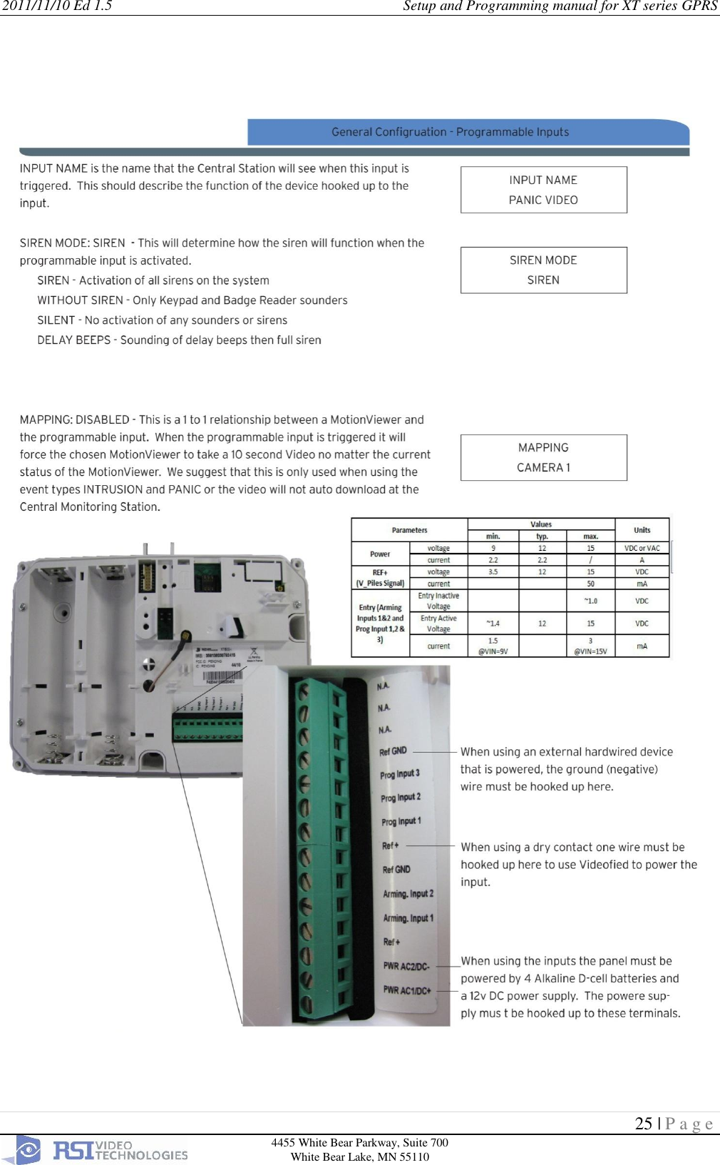
XT00 User Manual
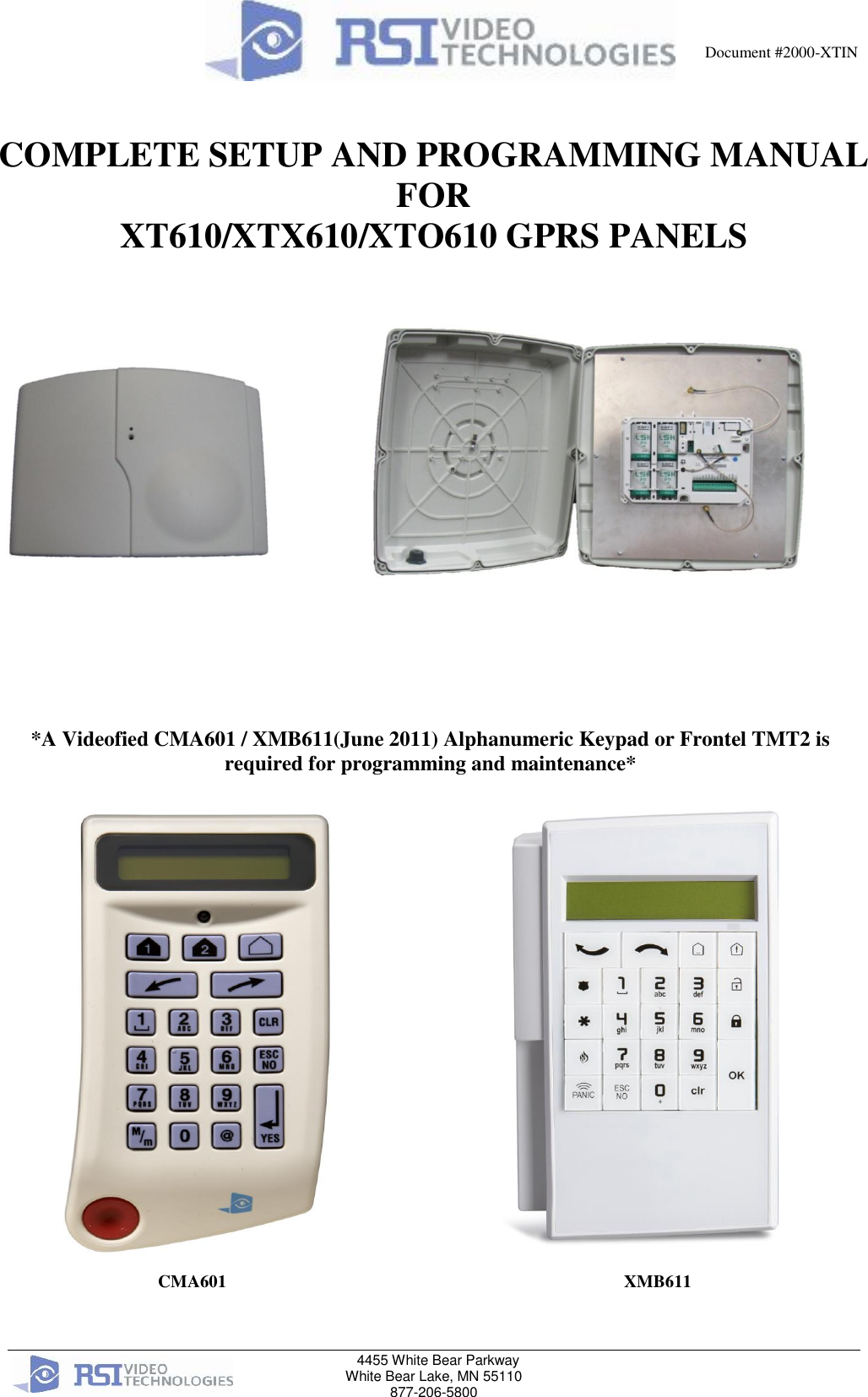
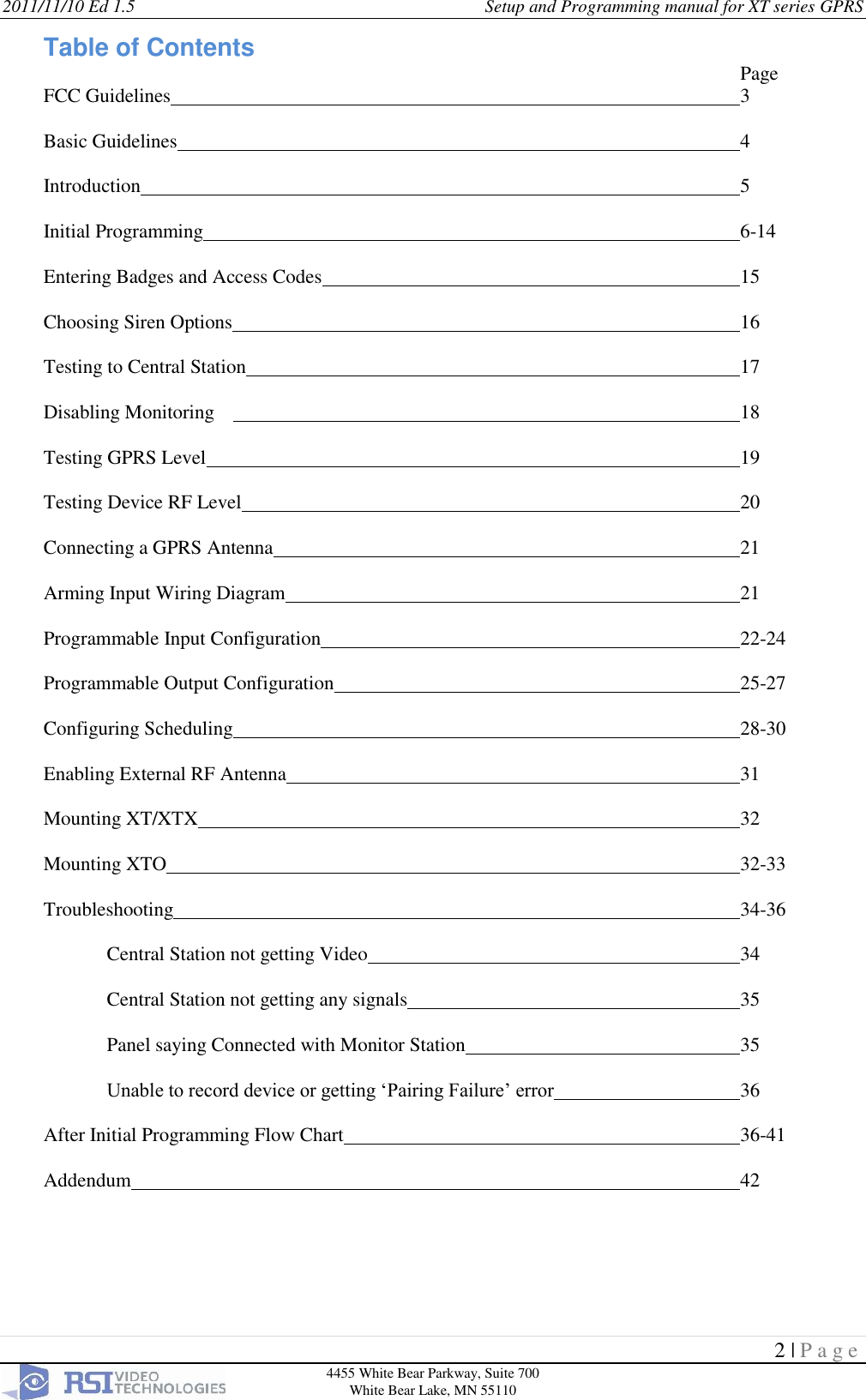
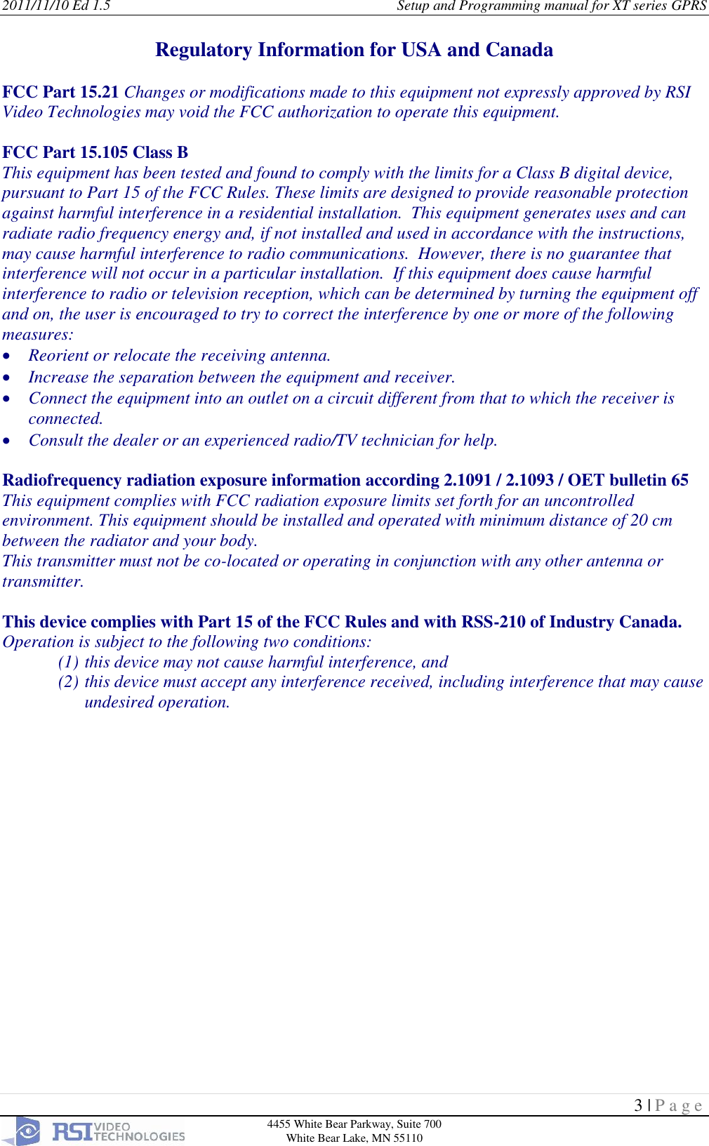
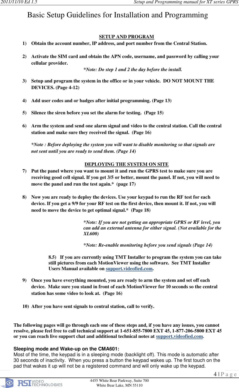
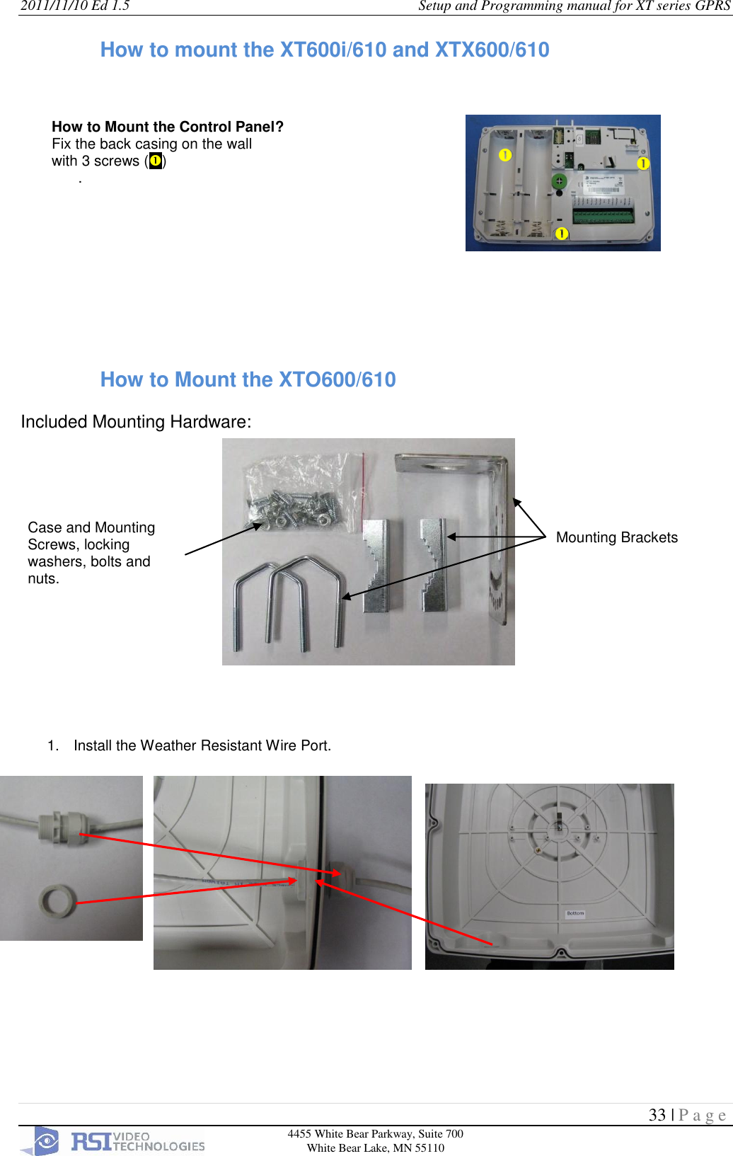
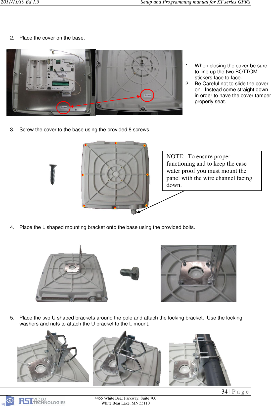
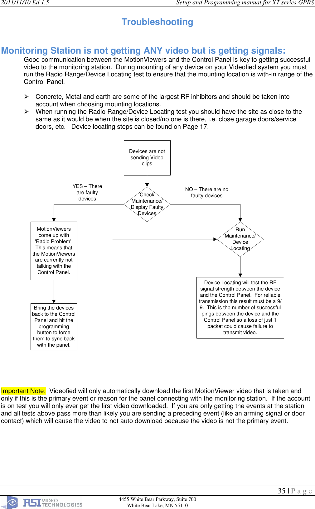
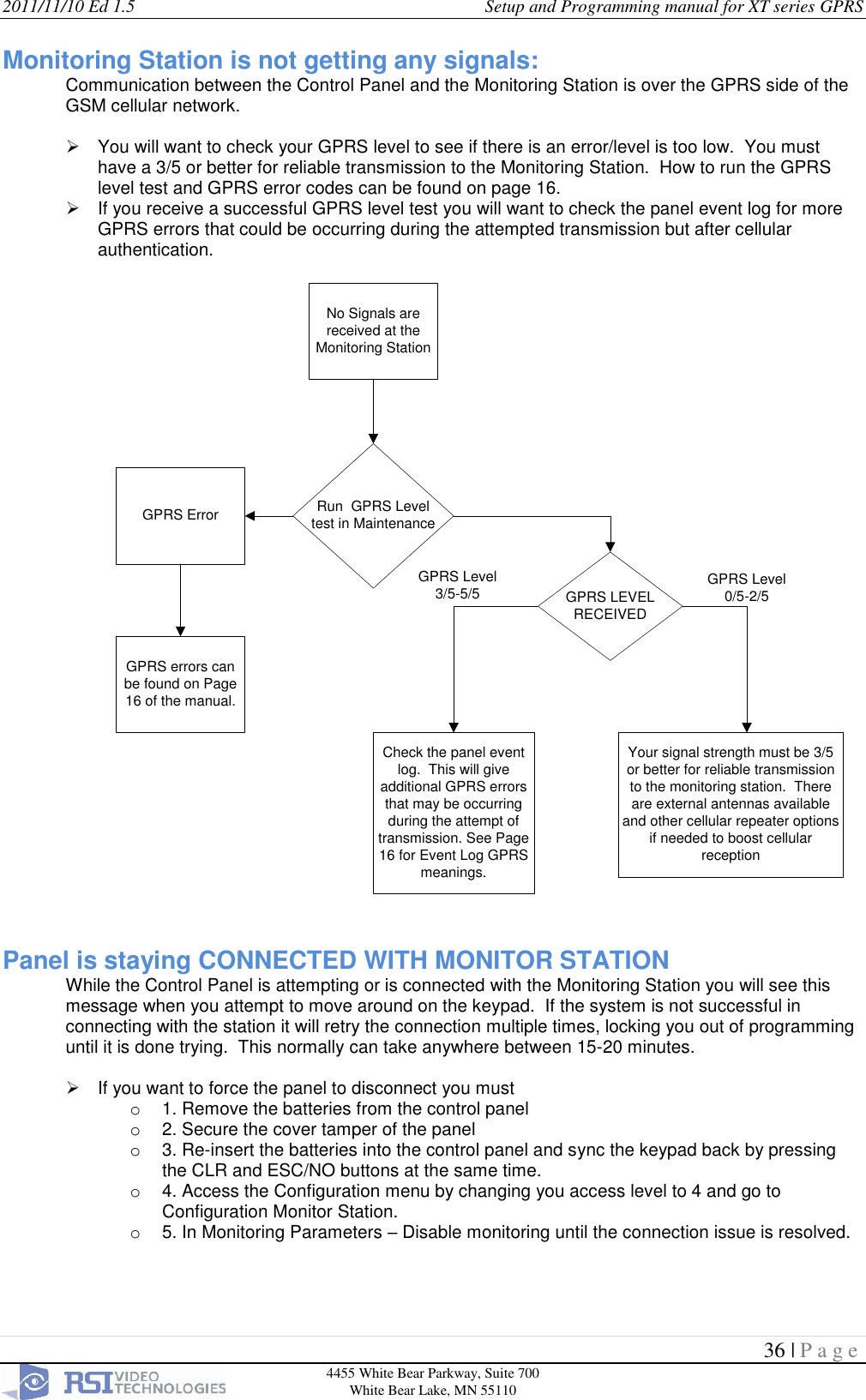
Installation Manual for XT-XTX-XTO series
Navigation menu
Upload a User Manual
Namespaces
Wiki Guide
HTML
PDF
Info
Views
User Manual
Discussion / Help
Navigation