RSI VIDEOTECHNOLOGIES XT00 Control panel User Manual Installation Manual for XT XTX XTO series
RSI VIDEOTECHNOLOGIES Control panel Installation Manual for XT XTX XTO series
Installation Manual for XT-XTX-XTO series

Document #2000-XTIN
4455 White Bear Parkway
White Bear Lake, MN 55110
877-206-5800
COMPLETE SETUP AND PROGRAMMING MANUAL
FOR
XT610/XTX610/XTO610 GPRS PANELS
*A Videofied CMA601 / XMB611(June 2011) Alphanumeric Keypad or Frontel TMT2 is
required for programming and maintenance*
CMA601
XMB611

2011/11/10 Ed 1.5 Setup and Programming manual for XT series GPRS
2 | P a g e
4455 White Bear Parkway, Suite 700
White Bear Lake, MN 55110
Table of Contents
Page
FCC Guidelines 3
Basic Guidelines 4
Introduction 5
Initial Programming 6-14
Entering Badges and Access Codes 15
Choosing Siren Options 16
Testing to Central Station 17
Disabling Monitoring 18
Testing GPRS Level 19
Testing Device RF Level 20
Connecting a GPRS Antenna 21
Arming Input Wiring Diagram 21
Programmable Input Configuration 22-24
Programmable Output Configuration 25-27
Configuring Scheduling 28-30
Enabling External RF Antenna 31
Mounting XT/XTX 32
Mounting XTO 32-33
Troubleshooting 34-36
Central Station not getting Video 34
Central Station not getting any signals 35
Panel saying Connected with Monitor Station 35
Unable to record device or getting ‘Pairing Failure’ error 36
After Initial Programming Flow Chart 36-41
Addendum 42

2011/11/10 Ed 1.5 Setup and Programming manual for XT series GPRS
3 | P a g e
4455 White Bear Parkway, Suite 700
White Bear Lake, MN 55110
Regulatory Information for USA and Canada
FCC Part 15.21 Changes or modifications made to this equipment not expressly approved by RSI
Video Technologies may void the FCC authorization to operate this equipment.
FCC Part 15.105 Class B
This equipment has been tested and found to comply with the limits for a Class B digital device,
pursuant to Part 15 of the FCC Rules. These limits are designed to provide reasonable protection
against harmful interference in a residential installation. This equipment generates uses and can
radiate radio frequency energy and, if not installed and used in accordance with the instructions,
may cause harmful interference to radio communications. However, there is no guarantee that
interference will not occur in a particular installation. If this equipment does cause harmful
interference to radio or television reception, which can be determined by turning the equipment off
and on, the user is encouraged to try to correct the interference by one or more of the following
measures:
Reorient or relocate the receiving antenna.
Increase the separation between the equipment and receiver.
Connect the equipment into an outlet on a circuit different from that to which the receiver is
connected.
Consult the dealer or an experienced radio/TV technician for help.
Radiofrequency radiation exposure information according 2.1091 / 2.1093 / OET bulletin 65
This equipment complies with FCC radiation exposure limits set forth for an uncontrolled
environment. This equipment should be installed and operated with minimum distance of 20 cm
between the radiator and your body.
This transmitter must not be co-located or operating in conjunction with any other antenna or
transmitter.
This device complies with Part 15 of the FCC Rules and with RSS-210 of Industry Canada.
Operation is subject to the following two conditions:
(1) this device may not cause harmful interference, and
(2) this device must accept any interference received, including interference that may cause
undesired operation.

2011/11/10 Ed 1.5 Setup and Programming manual for XT series GPRS
4 | P a g e
4455 White Bear Parkway, Suite 700
White Bear Lake, MN 55110
Basic Setup Guidelines for Installation and Programming
SETUP AND PROGRAM
1) Obtain the account number, IP address, and port number from the Central Station.
2) Activate the SIM card and obtain the APN code, username, and password by calling your
cellular provider.
*Note: Do step 1 and 2 the day before the install.
3) Setup and program the system in the office or in your vehicle. DO NOT MOUNT THE
DEVICES. (Page 4-12)
4) Add user codes and or badges after initial programming. (Page 13)
5) Silence the siren before you set the alarm for testing. (Page 15)
6) Arm the system and send one alarm signal and video to the central station. Call the central
station and make sure they received the signal. (Page 16)
*Note : Before deploying the system you will want to disable monitoring so that signals are
not sent until you are ready to send them. (Page 14)
DEPLOYING THE SYSTEM ON SITE
7) Put the panel where you want to mount it and run the GPRS test to make sure you are
receiving good cell signal. If you get 3/5 or better, mount the panel. If not, you will need to
move the panel and run the test again.* (page 17)
8) Now you are ready to deploy the devices. Use your keypad to run the RF test for each
device. If you get a 9/9 for your RF test on the first device, then mount it. If not, you will
need to move the device to get optimal signal.* (Page 18)
*Note: If you are not getting an appropriate GPRS or RF level, you
can add an external antenna for either signal. (Not available for the
XL600)
*Note: Re-enable monitoring before you send signals (Page 14)
8.5) If you are currently using TMT Installer to program the system you can take
still pictures from each MotionViewer using the software. See TMT Installer
Users Manual available on support.videofied.com.
9) Once you have everything mounted, you are ready to arm the system and set off each
device. Make sure you stand in front of each MotionViewer for 10 seconds so the central
station has some video to look at. (Page 16)
10) After you have sent signals to central station, call to verify.
The following pages will go through each one of these steps and, if you have any issues, you cannot
resolve, please feel free to call technical support at 1-651-855-7800 EXT 45, 1-877-206-5800 EXT 45
or you can reach live support chat and additional technical notes at support.videofied.com.
Sleeping mode and Wake-up on the CMA601:
Most of the time, the keypad is in a sleeping mode (backlight off). This mode is automatic after
30 seconds of inactivity. When you press a button the keypad wakes up. The first touch on the
pad that wakes it up will not be a registered command and will only wake up the keypad.

2011/11/10 Ed 1.5 Setup and Programming manual for XT series GPRS
5 | P a g e
4455 White Bear Parkway, Suite 700
White Bear Lake, MN 55110
Introduction:
Description:
The XT series control panel is a Videofied wireless, battery operated hybrid alarm system.
It is designed for residential, small business and commercial security applications. The XT
provides integrated Video Verification over GPRS.
The XT has programmable inputs and outputs. XT also features mapping where an
external input can be used to generate a video clip from a MotionViewer.
Internal RF range and GPRS range can be enhanced using external antennas.
Supervised Wireless Technology:
The XT, along with all Videofied devices, uses the patented S2View® - Spread Spectrum,
Videofied, Interactive, AES Encrypted Wireless technology, providing optimum
signal integrity and security.
The bi-directional RF communication path between all devices and the system control
panel guarantees high signal reliability. Integrated antennas eliminate protruding wires or
rods, which are difficult to install, unsightly to consumers and potentially troublesome if
damaged.
The panel supervises every device (excluding the remote key fob) to validate current
open/close state, tamper condition, serial number, date of manufacture, firmware revision,
and battery status.
Type
Specifications
Location In Manual
Audio
When a MotionViewer is
installed on the system you
may not have the siren sound
for less than 60 seconds
Page 26
Audio
If no MotionViewer is installed
on the system you may not
have the siren sound for less
than 240 seconds
Page 26
Delays
When a MotionViewer is
installed on the system the
Entry delay must be 45 seconds
Page 9
In order for an installation to be UL compliant you must follow the
specifications in the table below:
2011/11/10 Ed 1.5 Setup and Programming manual for XT series GPRS
6 | P a g e
4455 White Bear Parkway, Suite 700
White Bear Lake, MN 55110
SETUP MANUAL
FOR
XT SERIES GPRS PANEL
*THIS SYSTEM REQUIRES A CMA601/XMB611 or TMT INSTALLER SOFTWARE FOR
PROGRAMMING*
XT Initial Programming
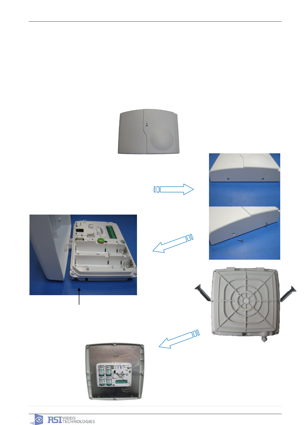
The cover will fold off the panel like a
book with the curved side acting like the
binding. The same technique is used
when placing the cover back onto the
unit.
Open the Control Panel
Using a #1 Phillips screwdriver, remove
the 2 screws holding the cover on.
When removing the
XTO cover, pull straight
off, do not slide it.
2011/11/10 Ed 1.5 Setup and Programming manual for XT series GPRS
7 | P a g e
4455 White Bear Parkway, Suite 700
White Bear Lake, MN 55110
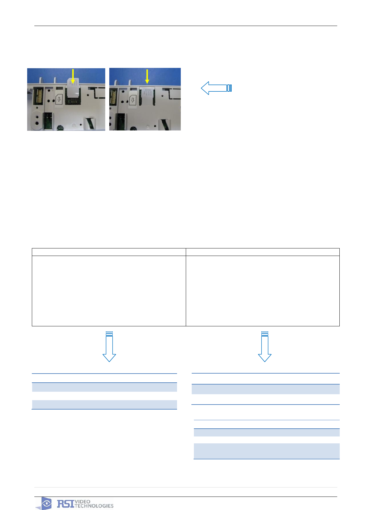
*The SIM card must NOT be inserted or removed while the panel is powered*
Powering the Panel
**THE CONTROL PANEL MUST BE CONNECTED TO AN EXTERAL POWER SUPPLY
WHEN SMS FEATURE IS ACTIVE**
Option 1: PP1
Option 2
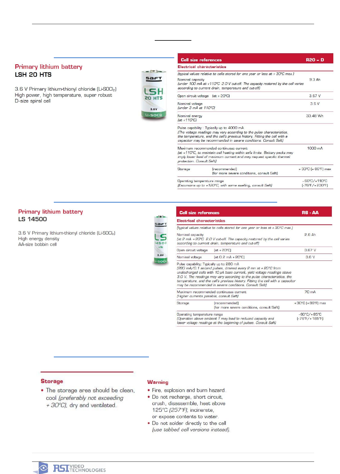
4 x LSH20 SAFT Lithium D-Cell
Used for Standalone or Xtender mode without
Programmable Inputs, Programmable Outputs, or
SMS
LSH20 Specifications:
Operating Temp: -76°F to +230°F
Storage Temp: Dry, Ventilated, 86°F Max
4 x E95VP Alkaline D-Cell + 12v 2amp DC Class 2
power supply (not supplied)
Used for Standalone or Xtender mode where
Programmable Inputs/Mapping, Programmable
Outputs, or SMS will be used
E95VP Specifications:
Operating Temp: 0°F to 130°F
E95VP Technical Specifciations
Nominal Capacity
8900 mA hours
Nominal Voltage
1.5 V
LSH20 Technical Specifications
Nominal Voltage
3.6 V
Open Circuit Voltage
3.67 V
Nominal Capacity
9.3 Ah
Power Supply Requirements
Output Voltage (volts)
12
Output Current (mA)
2000
Certifications
Class 2 (For UL
Compliance)
Install the SIM card
Slide SIM card into the slot.
Make sure it is aligned correctly.
2011/11/10 Ed 1.5 Setup and Programming manual for XT series GPRS
8 | P a g e
4455 White Bear Parkway, Suite 700
White Bear Lake, MN 55110
Obtaining XMB Keypad Special Characters
Obtaining CMA Keypad Special Characters
WARNINGS:
1. DO NOT USE ALKALINE BATTERIES IF
INSTALLING AN XTX/XTO GPRS BELOW
30° F, YOU MUST USE OPTION 1: PP1.
2. DO NOT INSTALL A TRANSFORMER
WHEN USING OPTION 1 (LITHIUM
BATTERIES).
2011/11/10 Ed 1.5 Setup and Programming manual for XT series GPRS
9 | P a g e
4455 White Bear Parkway, Suite 700
White Bear Lake, MN 55110
XT Programming
CMA Programming Device/Keypad
or
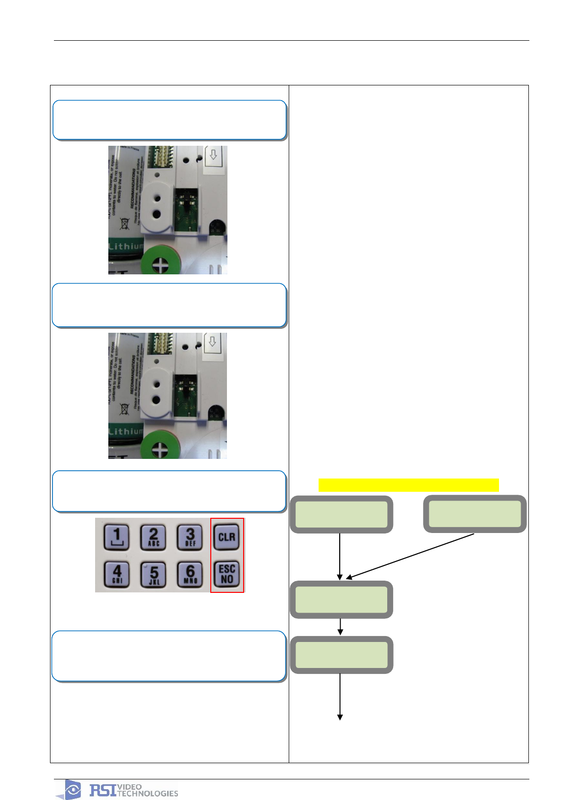
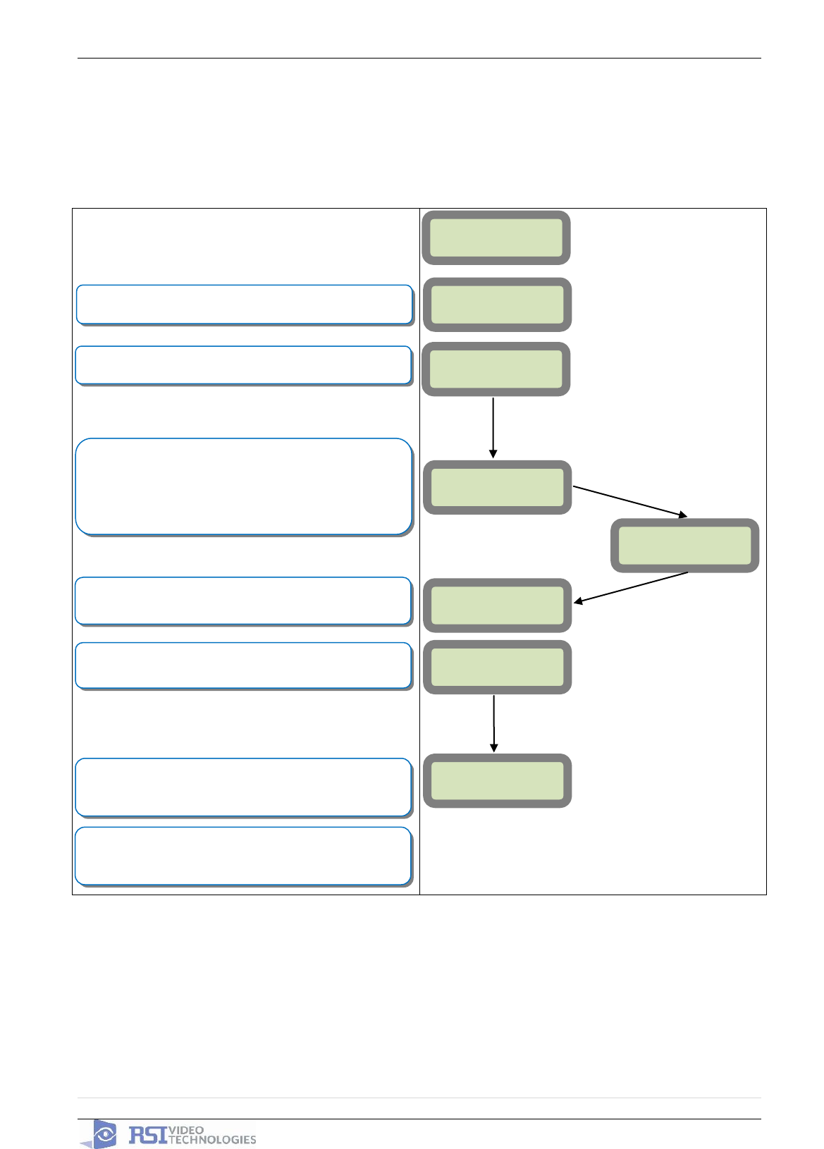
Reset the XT Panel:
Press and hold programming button () for 10sec until the
Indicator LED blinks twice
Press and instantly release the programming button ().
The indicator LED will blink once. The panel is now in ‘Learn
Mode’ for the CMA601 keypad.
CLR & ESC/NO
<======XX======>
Insert all three batteries into the CMA601 and press both the
ESC/NO and CLR keys at the same time and release. The
indicator LED on the keypad will blink rapidly.
YES
KEYPAD 1
RECORDED
RSI (c)2005
www.RsiAlarm.com
<- LANGUAGE : ->
ENGLISH
or for language selection
YES to apply
Other languages are available by scrolling with arrows.
ITALIANO, NEDERLANDS, DEUTSCH, CASTELLANO,
SVENSKA, PORTUGUES, FRANCAIS
Press YES for the selected one.
*Note: If you are having issues
pairing the keypad to the panel,
please refer to the troubleshooting
section.
2011/11/10 Ed 1.5 Setup and Programming manual for XT series GPRS
10 | P a g e
4455 White Bear Parkway, Suite 700
White Bear Lake, MN 55110
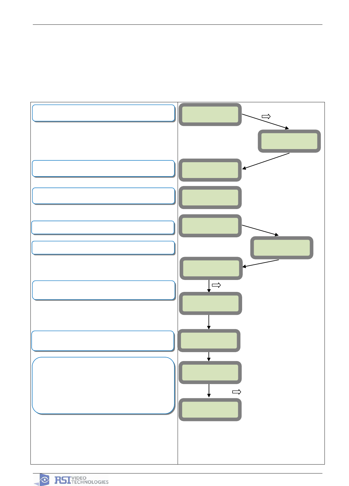
ENTER THE
INSTALLER CODE
4 TO 6 DIGITS
THEN YES
INSTALLER CODE:
INSTALLER CODE:
xxxx
YES
CONFIRM CODE
RE-ENTER CODE
CONFIRM CODE
xxxx
CODE NAME :
ACCESS 1
ENTRY COMPLETE
RADIO RANGE
TEST ?
RF TEST
x/9
YES
ESC/NO
ADJUSTING
TIME AND DATE
DATE (Year) :
09/ /
DATE (Year) :
10/ /
DATE (Month) :
10/01/
DATE (Month) :
10/11/
YES
YES
Wait while the screen changes
Use the Alphanumeric Keypad to enter the Installer Code
*This code is important to keep track of. There is no back
door to the system
You may name the installer code using the Alphanumeric
Keypad. If you leave the name blank it will default to
‘ACCESS 1’
Use the or to set the Year
Use the or to set the Month
RADIO RANGE
TEST ?
YES
The Radio Range test should be run during device
recording to ensure proper pairing with the control panel.
This test is the communication strength between the device
and the control panel. The keypad will display a real time
RF level for the device that is being tested. This test will run
until stopped and should be run for at least 30 seconds to
receive accurate results.
The RF level must be 9/9 for reliable transmission.
Wait while the screen changes
From here until the end of initial programming
you will not be able to step back to a previous
parameter. All parameters can be changed after
initial programming has been completed.
2011/11/10 Ed 1.5 Setup and Programming manual for XT series GPRS
11 | P a g e
4455 White Bear Parkway, Suite 700
White Bear Lake, MN 55110
DATE (Minutes) :
10:00
DATE (Minutes) :
10:53
03/06/09 10:53
ENTRY COMPLETE
CONNECTED TO
MONITOR.STATION?
ACCOUNT NUMBER?
ACCOUNT
NUMBER:99865123
PERIODIC TEST:
24 HOURS
Other periods are available:
48 hours, 24 hours, 12 hours,1 hour, No Test
Use arrows for the selection and press YES to confirm.
*We suggest at least a 24 hour test
or for period selection
and YES to apply
DATE (Day) :
09/06/01
DATE (Day) :
09/06/03
YES
YES
YES
Use the or to set the Day
Use the or to set the Hour – The system uses a
24 hour clock.
Use the or to set the Minutes
YES
Use the Alphanumeric Keypad to enter in a 4-8 digit account
number provided by the Central Station
TIME (HOUR) :
00:00
TIME (HOUR) :
10:00
YES
YOU MUST ALWAYS CHOOSE ‘YES’
TEST HOUR:
00:00
TEST MINUTE:
00:00
Use the arrow keys + YES to choose the Hour and Minute
the periodic test will happen.
2011/11/10 Ed 1.5 Setup and Programming manual for XT series GPRS
12 | P a g e
4455 White Bear Parkway, Suite 700
White Bear Lake, MN 55110
CODE/STATE
MODIFICATION ?
AREAS
CONFIGURATION
AREA NAME 1:
Other values are available:
2 min, 1 min, 45 sec
Use the arrows for the selection and YES to confirm.
Other values are available:
2 min, 1 min, 45 sec, 30 sec, 15 sec
Use the arrows for the selection and YES to confirm.
Use the Alphanumeric Keypad to name the area and press
YES. Repeat for all four areas. If you want to keep the
default area names press the ESC/NO key.
By default Area 1 is a delay area and Area 2, 3, & 4 are
instant areas.
CODE/STATE modification
These are the default transmitted events:
Device Alarm
Alert Alarm
Initialization Not Transmitted
Panel Batteries Alarm/End
AC Power Alarm/End
Phoneline Fault Not Transmitted
Tamper Alarm/End
Device Batt. Alarm/End
Radio Jamming Not Transmitted
Supervision Alarm/End
Periodic Test Alarm
Wrong Codes Not Transmitted
Duress Code Alarm
Alarm Memory Not Transmitted
Arm/Disarm Not Transmitted
If you would like to change the state
press YES and use the or to toggle
between:
Alarm – Appearance
Alarm/End – Appearance and Restoral
Not Transmitted – Not Transmitted
If you would like the default press ESC/NO
Wait
TRANS. STATE
MODIFICATION
List of all
events
YES
ESC/NO
ESC/NO
EXIT DELAY:
45 Sec
ENTRY DELAY:
15 Sec
ARMING OPTION:
From the host
ARMING OPTION:
Standalone
ARMING OPTION: Your choice will depend on how you are
arming the system.
From the host: Will make the XT a piggyback/xtender
system that arms and disarms off the latching of 9-12v on
the arming inputs.
Standalone: Will make the XT a solo system controlled by
arming and disarming using Videofied peripheral devices.
Go to Page 10 if you
will be choosing this
option
Go to Page 11 to continue
with standalone programming
2011/11/10 Ed 1.5 Setup and Programming manual for XT series GPRS
13 | P a g e
4455 White Bear Parkway, Suite 700
White Bear Lake, MN 55110
YES
ARMING OPTION :
From The Host
MODE:
Slow
MODE:
Fast
Mode Slow : Used for following the arming and disarming of
the host system. This will arm each device one at a time
conserving battery life.
Mode Fast : Used to instant arm all devices while sacrificing
battery life.
ENTRY DELAY
Enter the value for your Entry Delay up to 255 seconds and
press YES.
VALUE:(0-255)
(000):
TRANSMISSION
DELAY
Value: (0-600)
(000):
ARMING
CONFIRMATION
YES
Value: (0-240)
(0):
YES
YES
YES
YES
By entering a value using the keypad, up to 600 seconds,
the transmission of any event will be delayed that many
seconds.
Enter the value you would like for the Transmission Delay
and press YES
Arming Confirmation is the number of seconds of latched
voltage (where voltage must stayed latched after) the panel
will require before arming. This will be considered your exit
delay.
Enter the value you would like for the Arming Confirmation
and press YES
YES
Using the control panel as a Xtender system will only be able to arm and disarm by latching 9-12v to
one of the two inputs.
Arming input 1 will control the arming and disarming of devices in areas 1 and 2. Where devices in
area 1 are subject to the Entry Delay.
Arming input 2 will control the arming and disarming of devices in areas 3 and 4. Where devices in
area 3 are subject to the Entry Delay.
2011/11/10 Ed 1.5 Setup and Programming manual for XT series GPRS
14 | P a g e
4455 White Bear Parkway, Suite 700
White Bear Lake, MN 55110
YES
GPRS
PARAMETERS ?
APN CODE
APN CODE:
xxxxx.xxxxxx.xxx
Your APN code (Access Point Name) is given to you by your
Cellular Provider. Press YES to enter into the parameter
and use the Keypad to complete the code. Press YES to
confirm your entry and the arrow to move to the next
parameter.
USERNAME
PASSWORD
Your USERNAME is given to you by your Cellular Provider.
Press YES to enter into the parameter and use the
Keypad to complete the name. Press YES to confirm
your entry and the arrow to move to the next parameter.
PASSWORD:
xxxxxxxxxxxx
USERNAME:
xxxxxxxxxxx
YES
IP1 ADDRESS
IP1 ADDRESS:
xxx.xxx.xxx.xxx
DOMAIN NAME 1
YES
DOMAIN NAME 1:
xxxxx.xxx.xxx
PORT 1
PORT 1:
xxx
YES
YES
YES
YES
Your PASSWORD is given to you by your Cellular Provider.
Press YES to enter into the parameter and use the
Keypad to complete the name. Press YES to confirm
your entry and the arrow to move to the next parameter.
Your IP1 address is given to you by your Central Station.
Press YES to enter into the parameter and use the
Keypad to complete the address. Press YES to confirm
your entry and the arrow to move to the next parameter.
*You will use either a IP address or a Domain Name but not
both
*When entering an IP address you must enter all 12 digits
including preceeding 0s.
Your Domain Name is given to you by your Central Station.
Press YES to enter into the parameter and use the
Keypad to complete the name. Press YES to confirm
your entry and the arrow to move to the next parameter.
*You will use either a IP address or a Domain Name but not
both leave it blank if an IP has already been entered.
The Port is given to you by your Central Station. By default
the panel will use 888. If you need to modify the port press
the YES key to enter into the parameter and the keypad
to complete the port. Press YES to confirm and the
arrow to move to the next parameter.
GPRS PARAMETERS?
Continue through IP2 and TMT IP.
Once you have entered all valid parameters press ESC/NO
to return to the main menu then ESC/NO again to move to
the next parameter.
ESC/NO
ESC/NO
2011/11/10 Ed 1.5 Setup and Programming manual for XT series GPRS
15 | P a g e
4455 White Bear Parkway, Suite 700
White Bear Lake, MN 55110
Other XT setup with CMA600 keypad (Standalone ONLY)
Other setup (badges/codes, arming profiles, etc…) must be set with the CMA keypad
GPRS error codes
Codes
Error
010
SIM card not detected/not inserted
043
Provisioning problem, contact cellular provider
047
Typographical error in APN Code, IP Address, or Port
132
SIM card not activated
255
Cannot connect to cell tower
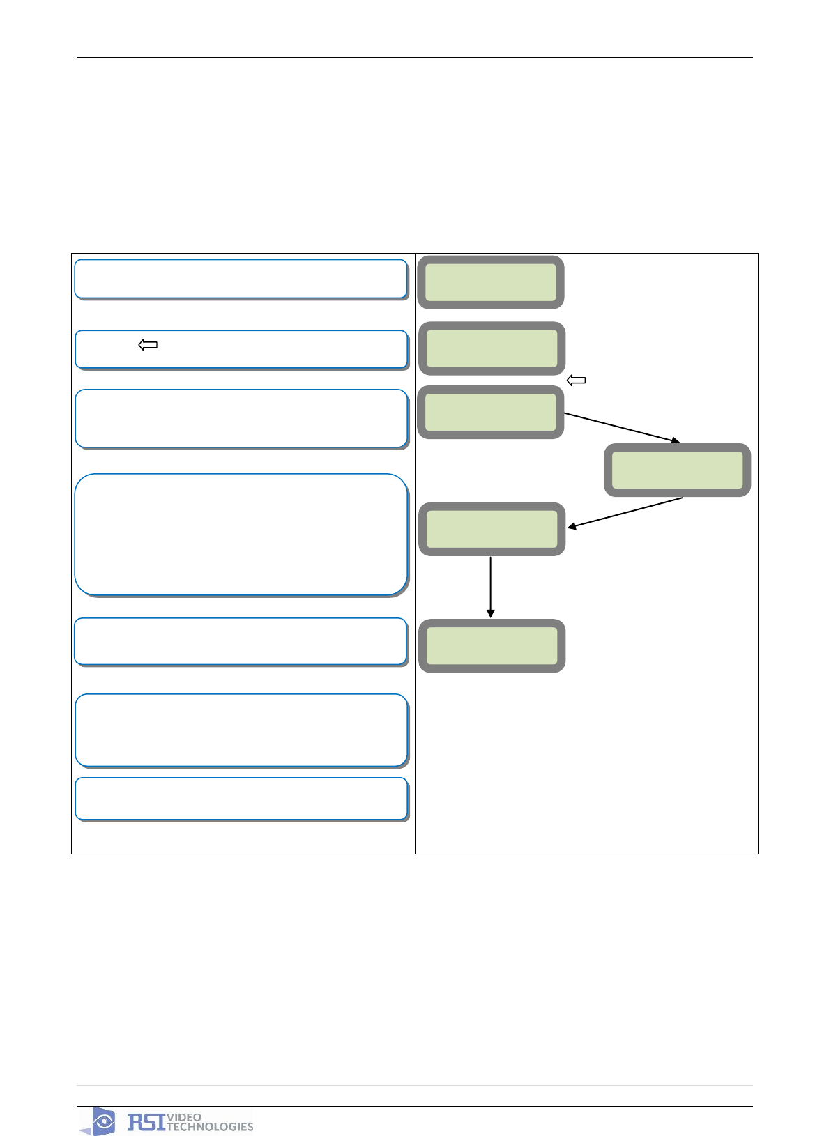
GPRS LEVEL?
TEST IN PROGRESS
YES = END
GPRS LEVEL
x/5
RECORDING
DEVICES
PRESS PROGRAM
BUTTON OF DEVICE
ENTERING A NEW
DEVICE?
CLOSE THE PANEL
OPERATION
COMPLETED?
YES
YES
YES
During the GPRS Level test the Modem will boot and
attempt to gain access to the internet to post a Level out of
5 or an error Code that will help troubleshoot why it cannot
connect. To keep the keypad awake use any keys on the
keypad except the YES, ESC/NO, and CLR keys. This test
can take up to 5 minutes. Once the level or error has
posted press YES to continue in programming.
*For explanation of GPRS errors see bottom of page.
Videofied will require a 3/5 or better for reliable transmission
of Video alarms
Each device has a unique programming button. Please
reference the Installation Sheet for the device you would like
to program.
Before completing programming make sure that all tampers
are depressed by verifying that each devices indicator LED is
off.
(Device Type) #
Recorded
RADIO RANGE
TEST?
RF TEST
x/9
RADIO RANGE
TEST?
AREA ALLOCATION:
NAME LOCATION:
FUNCTIONAL
DEVICE TEST?
YES or ESC/NO
Press YES on Radio Range Test? You must allow the Radio
Range test to run for at least 30 seconds (9/9) before
stopping the test by pressing YES.
Press ESC/NO if first Radio Range Test was successful.
Use the arrow keys to select the proper area. Devices that
need an entry/exit delay should be set to AREA 1. Devices
that must be instant trigger should be AREA 2, 3, or 4. Press
YES.
*Note: If you are having issues pairing a device to the panel,
please refer to the troubleshooting section.
2011/11/10 Ed 1.5 Setup and Programming manual for XT series GPRS
16 | P a g e
4455 White Bear Parkway, Suite 700
White Bear Lake, MN 55110
Entering a Badge or Access Code for Arming/Disarming
After Initial programming has been completed, you are not able to arm and disarm the system until
you enter a user code or badge (the installer code cannot arm and disarm the system). Codes can
be 4-6 digits and the 4th digit must be 2 values higher or lower than any other code on the system:
Example: User code 1234, next code cannot be 1235, 1236, 1233, or 1232 – These are reserved for
Silent Duress and Audible Duress. The XT system can accept up to 19 Badges or Access codes in
any combination.
If you are entering any additional codes press YES. If you
have completed entering Badges and Codes press and hold
ESC/NO for 5 seconds to return to the main manu.
Use the keypad to name the badge or code or leave it blank
for the default name : ACCESS #.
Confirm the code by re-entering.
Enter a 4-6 digit user code or present a badge to the reader
for 2 seconds.
Press the arrow to move to BADGES ACCESS CODES.
Enter the Installer code.
YES
YES
YES
YES
CONFIRM THE
CODE:
Badge
Presented
NAME OF BADGE:
ENTER A
BADGE/CODE
YES
YES
CODE NAME:
BADGE OR CODE
****
ENTRY COMPLETE
ENTER A
BADGE/CODE
BADGE OR CODE:
****
BADGES ACCESS
CODES
10/12/27 10:53
DISARMED LVL:3
2011/11/10 Ed 1.5 Setup and Programming manual for XT series GPRS
17 | P a g e
4455 White Bear Parkway, Suite 700
White Bear Lake, MN 55110
Changing Siren Options
After initial programming has been completed any sounder on the system will be enabled by default,
this includes the sounder on the Keypad and Badge Reader. While there is no way to disable the
sounding of the exit delay you are able to disable the intrusion sound.
Use the arrow keys to find the siren type you would like for
the chosen profile.
SIREN : All sounders are triggered during intrusion
SILENT : No sounders are triggered during intrusion
WITHOUT SIREN : Only arming device sounders are
triggered during intrusion.
DELAY BEEPS : Only delay beeps are sounded by the
interior siren.
The letter underneath the area describes which devices will
be armed when this profile is used. To change you must
press the corresponding area number to cycle through the
different letters.
A= All Devices Armed
D= All Devices Disarmed
E= Only external devices armed
P= Only perimeter device armed.
Use the to move to ALARM MODES PROGRAMMABLE
Use the arrow keys to find the arming profile you would like to
configure
Press the to move to CONFIGURATION
Enter the installer code for the system
Enter the installer code for the system
Press the arrow to move to ACCESS LVL.
Use your arrow keys to change the level to 4
YES
YES
ALARM:
WITHOUT SIREN
YES
BADGE OR CODE
GENERAL
PARAMETERS
SP2
SP1
YES
YES
BADGE OR CODE
****
YES
ALARM MODES
PROGRAMMABLE
ACCESS LVL: 4
FULLY ARMED
AREAS: 1234
STATE: AAAA
CONFIGURATION
ACCESS LEVEL
3
10/12/27 10:53
DISARMED LVL:3
2011/11/10 Ed 1.5 Setup and Programming manual for XT series GPRS
18 | P a g e
4455 White Bear Parkway, Suite 700
White Bear Lake, MN 55110
How to test to the dispatch center
Testing to the dispatch is done twice during installation. Once while you are programming the
system and then again once the installation has been completely finished. Although both will use the
same steps the initial test will be just confirmation using one device to verify the programming.
10/12/27 10:53
DISARMED LVL:3
ARMING THE
SYSTEM
SYSTEM ARMED
Enter a User code and press YES or present a badge to the
reader.
The system will sound the exit delay through the keypad and
badge reader.
INTRUSION
DETECTED
(DEVICE NAME)
(AREA)
The display will tell you that there has been an intrusion since
the last time the system was armed. Press YES to continue.
After pressing YES the keypad will tell you which device has
been triggered. Press YES to continue.
Once the delay has expired and the keypad says SYSTEM
ARMED, put motion in front of a MotionViewer. If the
MotionViewer is in area 1 you will need to wait for the entry
delay to expire before disarming the system. Once the
system has gone into alarm enter a User Code followed by
YES or present a badge to the reader to disarm.
The system will go back to the main menu automatically but
will not allow you to move around in programming until the
system has disconnected from the central station.
YES
YES
YES
YES
10/12/27 10:53
****
10/12/27 10:53
DISARMED LVL:3
SYSTEM ARMED
****
To verify that the system has transmitted you must contact
the Dispatch Center and have the account information ready
Note: Send 1 MotionViewer in at a time and verify with Central Station that they are
getting Alarm and Video before tripping another MotionViewer. This will save time with
the Central Station.
2011/11/10 Ed 1.5 Setup and Programming manual for XT series GPRS
19 | P a g e
4455 White Bear Parkway, Suite 700
White Bear Lake, MN 55110
How to Disable Monitoring
Disabling monitoring can be a useful tool in many situations. Before mounting devices and moving the
panel to find a good GPRS level, disabling monitoring will ensure that you will have access to programming
and that unnecessary signals are not sent to the monitoring station. When performing maintenance on the
system disabling monitoring until the issue has been resolved will ensure that you will have access to
programming throughout your troubleshooting.
Press YES on MONITORING ENABLED and use the
to change the value to DISABLED and press YES to lock it
in. Press and hold ESC/NO for 5 seconds to return to the
main menu.
Use the to move to CONFIGURATION MONITOR.
STATION
Press YES on MONITORING PARAMETERS
Press the to move to CONFIGURATION
Enter the installer code for the system
Enter the installer code for the system
Press the arrow to move to ACCESS LVL.
Use your arrow keys to change the level to 4
YES
YES
MONITORING:
DISABLED
YES
BADGE OR CODE
YES
YES
BADGE OR CODE
****
YES
CONFIGURATION
MONITOR. STATION
ACCESS LVL: 4
MONITORING
PARAMETERS
MONITORING
ENABLED
CONFIGURATION
ACCESS LEVEL
3
10/12/27 10:53
DISARMED LVL:3
GENERAL
PARAMETERS
2011/11/10 Ed 1.5 Setup and Programming manual for XT series GPRS
20 | P a g e
4455 White Bear Parkway, Suite 700
White Bear Lake, MN 55110
How to test GPRS for deployment of panel
Before the system is mounted you will need to check the GPRS level to make sure it is adequate. If the level
is 3/5 or better you can mount the control panel in that location.
GPRS Errors when running GPRS LEVEL
Codes
Error
010
SIM card not detected/not inserted
043
Provisioning problem, contact cellular provider
132
SIM card not activated
255
Cannot connect to cell tower
GPRS Codes in Event Log
Codes
Error
256
Cannot connect to cell tower
11
SIM not ready if multiples, SIM not detect if only one
48
Signal rejected by host, IP, Domain Name, or Port are incorrect
10/12/27 10:53
DISARMED LVL:3
GPRS LEVEL
TEST IN PROG.
YES = END
Press the arrow to move to MAINTENANCE.
Press the arrow to move to GPRS LEVEL.
GPRS LEVEL
Press and hold ESC/NO for 5 seconds to return to the main
menu.
This test can take up to 5 minutes to complete. Pressing the
YES, ESC/NO, or CLR buttons will prematurely end the test.
This test will automatically issue the results to the display of
the keypad when it has completed with either a level out of 5
(0/5-5/5) or an error code (listed below). Use the arrow keys
to keep the keypad awake during the test.
YES
YES
MAINTENANCE
GPRS LEVEL
X/5
Press YES on GPRS LEVEL to start the test.
2011/11/10 Ed 1.5 Setup and Programming manual for XT series GPRS
21 | P a g e
4455 White Bear Parkway, Suite 700
White Bear Lake, MN 55110
How to test RF for deployment of devices
Running the RF test during the mounting of devices is key to a successful Videofied installation. This test
will ensure that all devices have adequate communication with the control panel. All Videofied devices are
bi-directional which allows the system to ping the device and expect a response. The number of successful
responses out of 9 will be displayed on the keypad for the device you are running the test for. This is also a
relative range that will change in real time as you walk further away from the control panel and back closer.
10/12/27 10:53
DISARMED LVL:3
DEVICE LOCATING
RF TEST
0/9
Press the arrow to move to MAINTENANCE
Press the arrow to move to DEVICE LOCATING
(DEVICE NAME)
Press and hold ESC/NO for 5 seconds to return to the main
menu.
This test will run as long as you need it to. Pressing the
YES, ESC/NO, or CLR buttons will end the test. This test
will show the results on the display of the keypad relative to
the number of successful pings to the panel. It is required to
run the test for at least 30 seconds at the mounting location
for accurate results and to have a 9/9 for reliable
transmission of alarms and video. Press YES when you are
finished with the test.
YES
YES
MAINTENANCE
Press YES on DEVICE LOCATING to get to the list of
devices. Use the arrow keys to find the device you would like
to run the test for.
(DEVICE NAME)
YES
YES
Once all devices are checking in at 9/9, you are ready to test
the full system to your central station. After arming and
tripping each device call the central station and verify alarm
and video of each device with dispatch.
Now you are ready to show the customer how to use the
system.
NOTE: To insure proper operation of the system you must get 9/9 with each device
before mounting.
2011/11/10 Ed 1.5 Setup and Programming manual for XT series GPRS
22 | P a g e
4455 White Bear Parkway, Suite 700
White Bear Lake, MN 55110
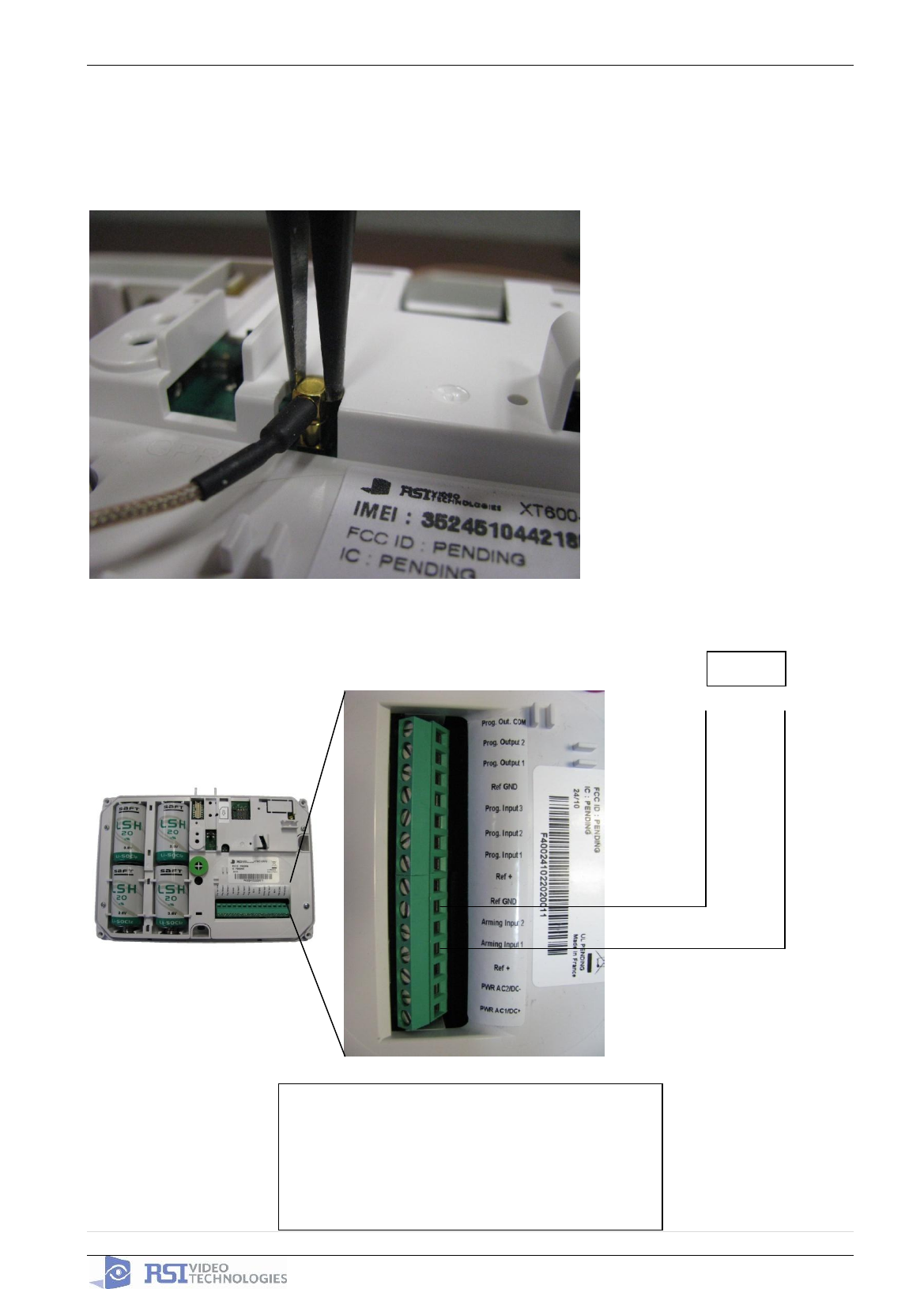
GPRS Antenna Connection
! WARNING !
Use caution before removing antenna connection. Damaged antenna connector is NOT
covered under warranty.
Using needle nose pliers, be
sure to only grab the
connector and pull directly up
Arming Input Wiring Diagram
+
_
HOST
When in Arm From Host mode the Videofied
system will only arm and disarm when 9-12v
is supplied and sustained.
Arming Input 1 will arm/disarm Areas 1 & 2
Arming Input 2 will arm/disarm Areas 3 & 4

2011/11/10 Ed 1.5 Setup and Programming manual for XT series GPRS
23 | P a g e
4455 White Bear Parkway, Suite 700
White Bear Lake, MN 55110
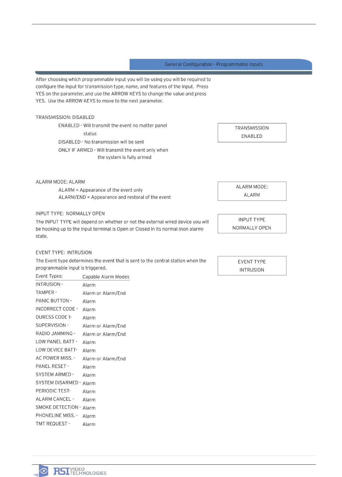
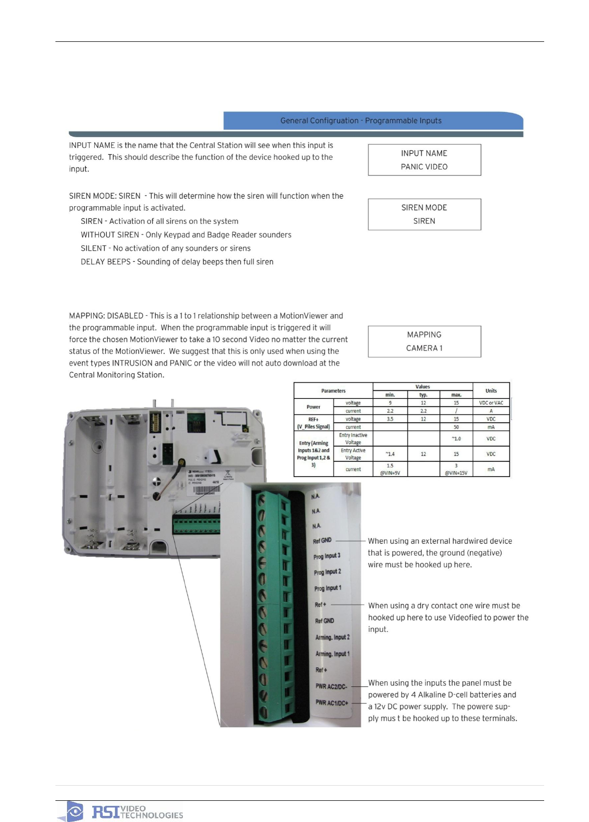
General Programmable Input Configuration
2011/11/10 Ed 1.5 Setup and Programming manual for XT series GPRS
24 | P a g e
4455 White Bear Parkway, Suite 700
White Bear Lake, MN 55110
2011/11/10 Ed 1.5 Setup and Programming manual for XT series GPRS
25 | P a g e
4455 White Bear Parkway, Suite 700
White Bear Lake, MN 55110
2011/11/10 Ed 1.5 Setup and Programming manual for XT series GPRS
26 | P a g e
4455 White Bear Parkway, Suite 700
White Bear Lake, MN 55110
2011/11/10 Ed 1.5 Setup and Programming manual for XT series GPRS
27 | P a g e
4455 White Bear Parkway, Suite 700
White Bear Lake, MN 55110
2011/11/10 Ed 1.5 Setup and Programming manual for XT series GPRS
28 | P a g e
4455 White Bear Parkway, Suite 700
White Bear Lake, MN 55110

2011/11/10 Ed 1.5 Setup and Programming manual for XT series GPRS
29 | P a g e
4455 White Bear Parkway, Suite 700
White Bear Lake, MN 55110
2011/11/10 Ed 1.5 Setup and Programming manual for XT series GPRS
30 | P a g e
4455 White Bear Parkway, Suite 700
White Bear Lake, MN 55110
2011/11/10 Ed 1.5 Setup and Programming manual for XT series GPRS
31 | P a g e
4455 White Bear Parkway, Suite 700
White Bear Lake, MN 55110
2011/11/10 Ed 1.5 Setup and Programming manual for XT series GPRS
32 | P a g e
4455 White Bear Parkway, Suite 700
White Bear Lake, MN 55110
How to enable the External RF Antenna
The XTO 600/610 control panels have built in High Gain RF and GPRS antennas. The GPRS external
comes pre-activated and hooked up, while the RF antenna is hooked up but needs to be activated in
Configuration after you have completed initial programming. The following steps will walk you through how
to enable the High Gain RF antenna after initial programming.
Left or Right arrow until you see RADIO OPTIONS and press
YES. Use the arrow keys to change it to External and press
YES.
Enter the Installer Code
Press the arrow to move to CONFIGURATION
Enter the Installer code.
Press the arrow to move to ACCESS LEVEL #.
Press YES and use the to move the level to 4
YES
YES
SITE
IDENTIFICATION
RADIO OPTIONS:
EXTERNAL
GENERAL
PARAMETERS
BADGE OR CODE:
****
CONFIGURATION
YES
YES
BADGE OR CODE:
****
YES
ACCESS LVL:
4
ACCESS LEVEL
3
10/12/27 10:53
DISARMED LVL:3
2011/11/10 Ed 1.5 Setup and Programming manual for XT series GPRS
33 | P a g e
4455 White Bear Parkway, Suite 700
White Bear Lake, MN 55110
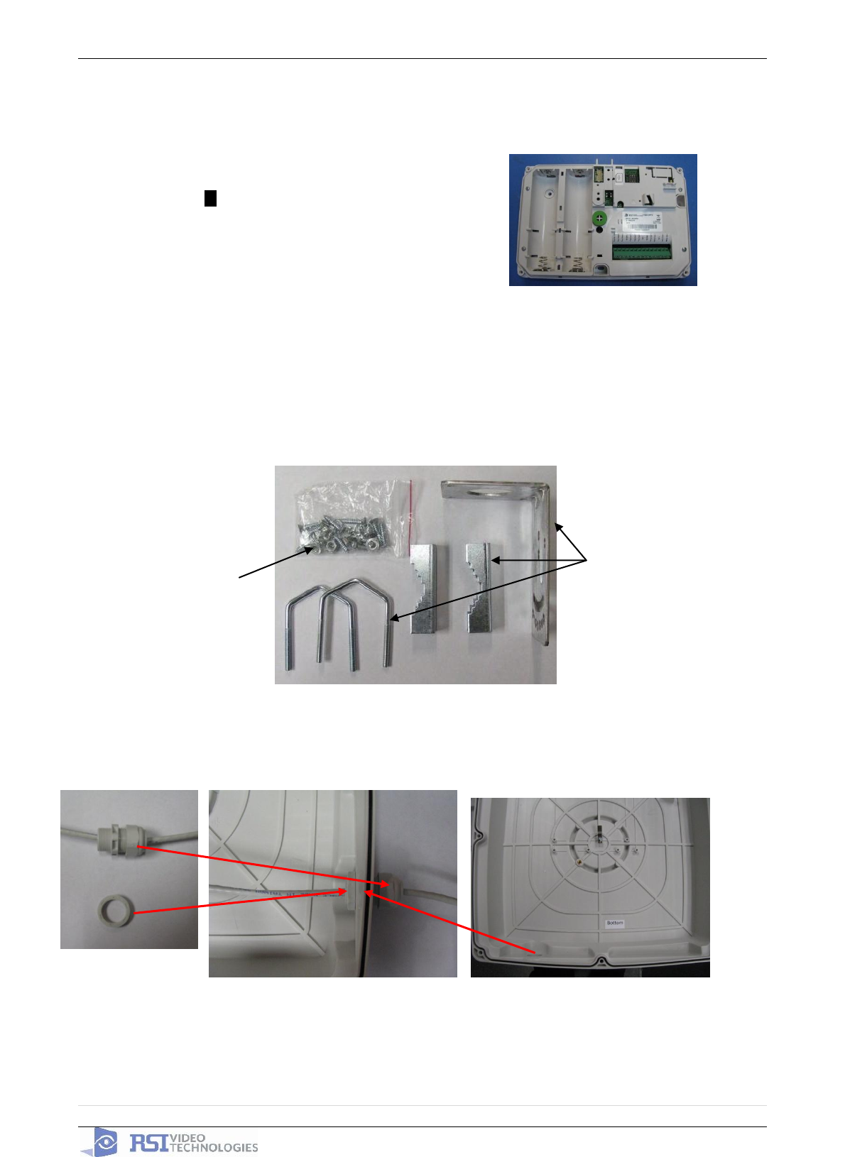
How to mount the XT600i/610 and XTX600/610
How to Mount the XTO600/610
Included Mounting Hardware:
1. Install the Weather Resistant Wire Port.
How to Mount the Control Panel?
Fix the back casing on the wall
with 3 screws ()
.
Mounting Brackets
Case and Mounting
Screws, locking
washers, bolts and
nuts.
2011/11/10 Ed 1.5 Setup and Programming manual for XT series GPRS
34 | P a g e
4455 White Bear Parkway, Suite 700
White Bear Lake, MN 55110
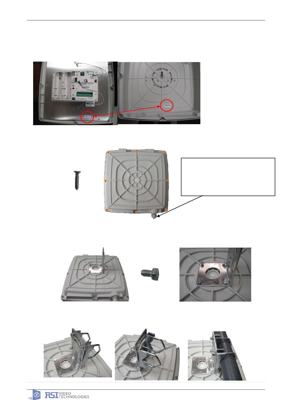
NOTE: To ensure proper
functioning and to keep the case
water proof you must mount the
panel with the wire channel facing
down.
2. Place the cover on the base.
3. Screw the cover to the base using the provided 8 screws.
4. Place the L shaped mounting bracket onto the base using the provided bolts.
5. Place the two U shaped brackets around the pole and attach the locking bracket. Use the locking
washers and nuts to attach the U bracket to the L mount.
1. When closing the cover be sure
to line up the two BOTTOM
stickers face to face.
2. Be Careful not to slide the cover
on. Instead come straight down
in order to have the cover tamper
properly seat.
2011/11/10 Ed 1.5 Setup and Programming manual for XT series GPRS
35 | P a g e
4455 White Bear Parkway, Suite 700
White Bear Lake, MN 55110
Troubleshooting
Monitoring Station is not getting ANY video but is getting signals:
Good communication between the MotionViewers and the Control Panel is key to getting successful
video to the monitoring station. During mounting of any device on your Videofied system you must
run the Radio Range/Device Locating test to ensure that the mounting location is with-in range of the
Control Panel.
Concrete, Metal and earth are some of the largest RF inhibitors and should be taken into
account when choosing mounting locations.
When running the Radio Range/Device Locating test you should have the site as close to the
same as it would be when the site is closed/no one is there, i.e. close garage doors/service
doors, etc. Device locating steps can be found on Page 17.
Devices are not
sending Video
clips
Check
Maintenance/
Display Faulty
Devices
YES – There
are faulty
devices
NO – There are no
faulty devices
Run
Maintenance/
Device
Locating
MotionViewers
come up with
‘Radio Problem’.
This means that
the MotionViewers
are currently not
talking with the
Control Panel.
Bring the devices
back to the Control
Panel and hit the
programming
button to force
them to sync back
with the panel.
Device Locating will test the RF
signal strength between the device
and the Control Panel. For reliable
transmission this result must be a 9/
9. This is the number of successful
pings between the device and the
Control Panel so a loss of just 1
packet could cause failure to
transmit video.
Important Note: Videofied will only automatically download the first MotionViewer video that is taken and
only if this is the primary event or reason for the panel connecting with the monitoring station. If the account
is on test you will only ever get the first video downloaded. If you are only getting the events at the station
and all tests above pass more than likely you are sending a preceding event (like an arming signal or door
contact) which will cause the video to not auto download because the video is not the primary event.
2011/11/10 Ed 1.5 Setup and Programming manual for XT series GPRS
36 | P a g e
4455 White Bear Parkway, Suite 700
White Bear Lake, MN 55110
Monitoring Station is not getting any signals:
Communication between the Control Panel and the Monitoring Station is over the GPRS side of the
GSM cellular network.
You will want to check your GPRS level to see if there is an error/level is too low. You must
have a 3/5 or better for reliable transmission to the Monitoring Station. How to run the GPRS
level test and GPRS error codes can be found on page 16.
If you receive a successful GPRS level test you will want to check the panel event log for more
GPRS errors that could be occurring during the attempted transmission but after cellular
authentication.
No Signals are
received at the
Monitoring Station
Run GPRS Level
test in Maintenance
GPRS Error
GPRS errors can
be found on Page
16 of the manual.
Check the panel event
log. This will give
additional GPRS errors
that may be occurring
during the attempt of
transmission. See Page
16 for Event Log GPRS
meanings.
GPRS LEVEL
RECEIVED
Your signal strength must be 3/5
or better for reliable transmission
to the monitoring station. There
are external antennas available
and other cellular repeater options
if needed to boost cellular
reception
GPRS Level
0/5-2/5
GPRS Level
3/5-5/5
Panel is staying CONNECTED WITH MONITOR STATION
While the Control Panel is attempting or is connected with the Monitoring Station you will see this
message when you attempt to move around on the keypad. If the system is not successful in
connecting with the station it will retry the connection multiple times, locking you out of programming
until it is done trying. This normally can take anywhere between 15-20 minutes.
If you want to force the panel to disconnect you must
o 1. Remove the batteries from the control panel
o 2. Secure the cover tamper of the panel
o 3. Re-insert the batteries into the control panel and sync the keypad back by pressing
the CLR and ESC/NO buttons at the same time.
o 4. Access the Configuration menu by changing you access level to 4 and go to
Configuration Monitor Station.
o 5. In Monitoring Parameters – Disable monitoring until the connection issue is resolved.
2011/11/10 Ed 1.5 Setup and Programming manual for XT series GPRS
37 | P a g e
4455 White Bear Parkway, Suite 700
White Bear Lake, MN 55110
Unable to record device or getting ‘Pairing Failure’ error
This usually occurs when the device still has a pairing key from a previous system or setup. To
perform a pairing key override:
o 1. Remove all batteries from the device.
o 2. Make sure your system is ready to record devices:
o A. If learning in the keypad, press the panel’s programming button. DO NOT
HOLD THE PANEL’S PROGRAMMING BUTTON
o B. If learning in additional devices, make sure the keypad reads ‘Press
Programming Button Of Device’
o 3. Insert a single battery into the device.
o 4. Wait 1 second for device to power up.
o 5. Press programming button of device (for keypads press ‘CLR’ & ‘ESC/NO’ keys at the
same time)
For the 4-button remote keyfobs the process is slightly different:
o 1. Press and hold the ‘ON’ and ‘OFF’ keys at the same time for 12 seconds
o 2. Wait 1 second
o 3. Press and hold the ‘ON’ and ‘OFF’ keys at the same time for 5 seconds, you should
hear 4 beeps from the keyfob.
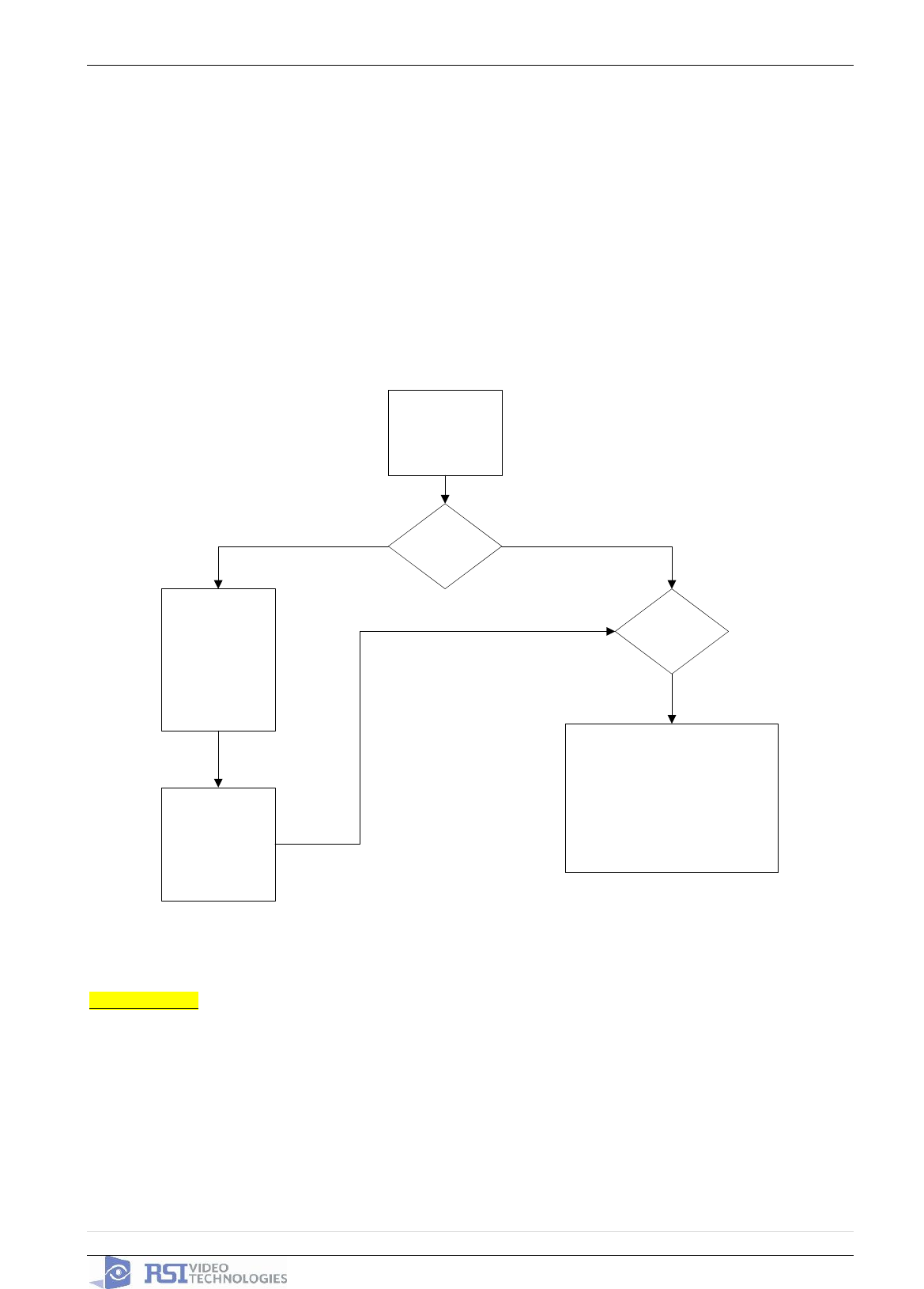
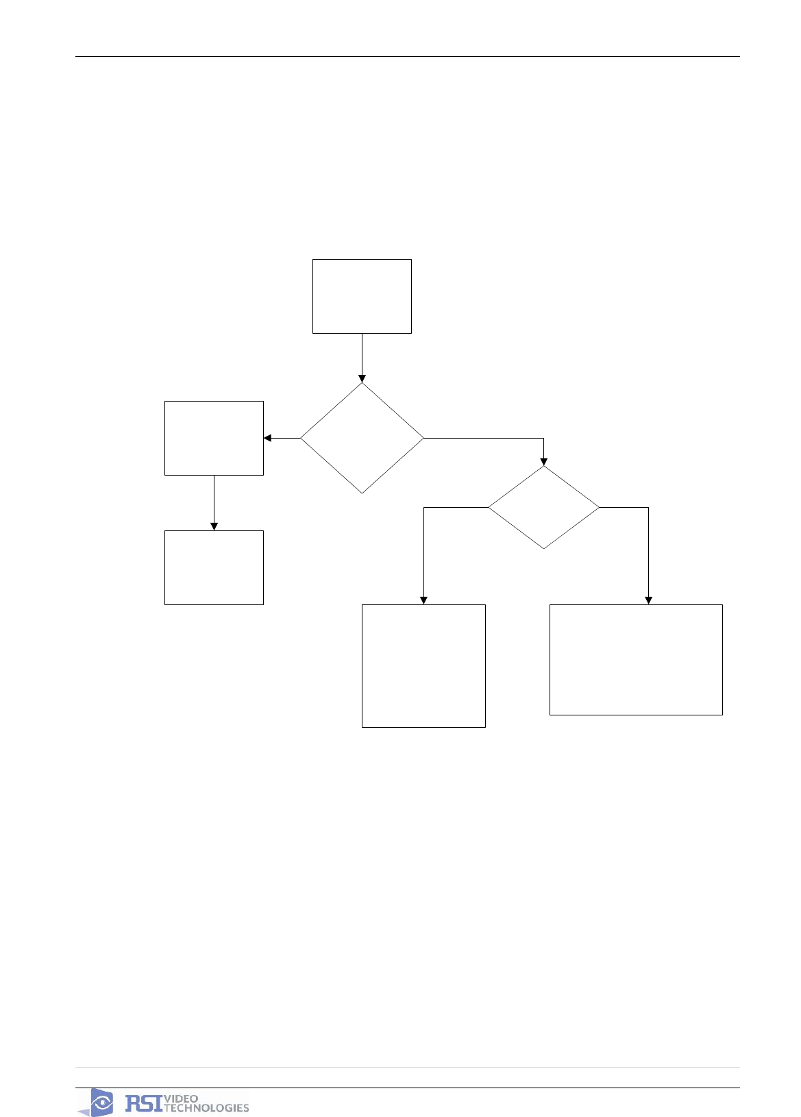
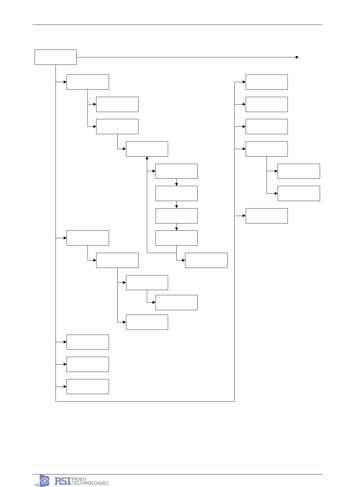
XT -SERIES ‘AFTER INITIAL PROGRAMMING’ FLOW CHART
2011/11/10 Ed 1.5 Setup and Programming manual for XT series GPRS
38 | P a g e
4455 White Bear Parkway, Suite 700
White Bear Lake, MN 55110
CONFIGURATION
GPRS
PARAMETERS
PROGRAMMABLE
INPUTS
XTENDER
SITE
IDENTIFICATION
GENERAL
PARAMETERS
RADIO OPTION
EXTERNAL
ANTENNA
ALARM MODE SP2
ALARM MODE SP1
FULLY ARMED
ALARM MODES
PROGRAMMABLE
EXIT DELAY
45sec
ENTRY DELAY
15sec
SIREN DURATION
TAMPER 90sec
SIREN DURATION
INTRUSION 90sec
AREAS
DEVICES
AREAS AND
DEVICES
EMAIL SENDER
VIDEOMAIL ALARM
ADDRESS
RESPONDING
PARTY LIST
DELAY BEEPS
ENABLED
AUTO ARMING
DELAY DISABLED
WARNING BIP
ENABLED
SCHEDULING
ALARM CODES
PERIODIC TEST
MONITORING
PARAMETERS
CONFIGURATION
MONITOR. STATION
Not Supported in the
North American Market
Page 36 Page 37Page 37 Page 38 Page 39
PROGRAMMABLE
OUTPUTS
PROGRAMMABLE
INPUTS
2011/11/10 Ed 1.5 Setup and Programming manual for XT series GPRS
39 | P a g e
4455 White Bear Parkway, Suite 700
White Bear Lake, MN 55110
GENERAL
PARAMETERS
SITE
IDENTIFICATION
PANEL PHONE
NUMBER
NAME OR
ADDRESS
XTENDER
ARMING
OPTION
STANDALONE
ENTRY DELAY
000
TRANSMISSION
DELAY 000
ARMING
CONFIRMATION
0
ARMING MODE
SLOW
PROGRAMMABLE
INPUTS
PROGRAMMABLE
INPUT 1
TRANSMISSION
DISABLED
ALARM MODE
ALARM
INPUT TYPE
NORMALLY OPEN
EVENT TYPE
INTRUSION
INPUT NAME
SIREN MODE
MAPPING
DISABLED
PROGRAMMABLE
INPUT 2
PROGRAMMABLE
INPUT 3
GPRS
PARAMETERS
APN CODE
USERNAME
PASSWORD
IP ADDRESS 1
0.0.0.0
DOMAIN NAME 1
PORT 1
888
IP ADDRESS 2
0.0.0.0
DOMAIN NAME 2
PORT 2
888
TMT IP
ADDRESS
0.0.0.0
DOMAIN TMT
PORT TMT
888
PAQUET SIZE
512
DATA TIMEOUT
20
SMTP GPRS
PORT GPRS
3389
MAX TCP
PACKET
RINGTONE
OFF
RADIO OPTIONS
INTERNAL ANTENNA
PROGRAMMABLE
OUTPUTS
PROGRAMMABLE
OUTPUT 1
STATUS
DISABLED
LENGTH ACTIV.
180 sec
EVENT TYPE
INTRUSION
OUTPUT NAME
PROGRAMMABLE
OUTPUT 2
GENERAL PARAMETERS
2011/11/10 Ed 1.5 Setup and Programming manual for XT series GPRS
40 | P a g e
4455 White Bear Parkway, Suite 700
White Bear Lake, MN 55110
ALARM MODES PROGRAMMABLE / RESPONDING PARTY LIST
ALARM MODES
PROGRAMMABLE
DESIGNATION
MODE
ALARM:
SIREN
AREAS: 1234
STATE: AAAA
ALARM MODE SP2
DESIGNATION
MODE
ALARM:
SIREN
AREAS: 1234
STATE: AAAA
ALARM MODE SP1
ALARM:
SIREN
AREAS:1234
STATE: AAAA
FULLY ARMED
EMAIL SENDER
ENTER NEW EMAIL
ADDRESS
SELECT/MODIFY
EMAIL ADDRESS
VIDEOMAIL ALARM
ADDRESS
RESPONDING
PARTY LIST
Not supported in the North
American Market
2011/11/10 Ed 1.5 Setup and Programming manual for XT series GPRS
41 | P a g e
4455 White Bear Parkway, Suite 700
White Bear Lake, MN 55110
AREAS AND DEVICES
AREAS AND
DEVICES
EXIT DELAY
45sec
ENTRY DELAY
15sec
SIREN DURATION
TAMPER 90sec
SIREN DURATION
INTRUSION 90sec
CHANGING NAME
AREA
LIST OF DEVICES
IN AREA
AREA CONTENT
LIST OF AREAS
AREAS
24H SIREN MODE
24 HOUR DEVICE
DISABLED
CHANGING AREA
DEVICE
CHANGING NAME
DEVICE
DELETE DEVICE
LIST OF DEVICES
DEVICE
CONFIGURATION
ADD A NEW
DEVICE
DEVICES
DELAY BEEPS
ENABLED
AUTO ARMING
DELAY DISABLED
SCEDULING
SCHEDULING OFF
CALENDAR
MANAGEMENT
WARNING BIP
DISABLED
2011/11/10 Ed 1.5 Setup and Programming manual for XT series GPRS
42 | P a g e
4455 White Bear Parkway, Suite 700
White Bear Lake, MN 55110
CONFIGURATION MONITOR. STATION
CONFIGURATION
MONITOR. STATION
TRANS. STATE
MODIFICATION
ALARM CODES
SYSTEM ARMED
DISABLED
TEST HOUR
15:00
PERIODIC TEST
24 HOURS
PERIODIC TEST
ACCOUNT
NUMBER
MONITORING
ENABLED
MONITORING
PARAMETERS
LIST OF
TRANSMITTED
EVENTS
PPP CONNECTION
PPP USER NAME
PPP PASSWORD
DOMAIN NAME
2011/11/10 Ed 1.5 Setup and Programming manual for XT series GPRS
43 | P a g e
4455 White Bear Parkway, Suite 700
White Bear Lake, MN 55110
Addendum
1. LSH20 Control Panel Batteries:
2. LS14500 Peripheral Batteries: Excludes SE601 and SE651
3. Lithium Battery Storage:

2011/11/10 Ed 1.5 Setup and Programming manual for XT series GPRS
44 | P a g e
4455 White Bear Parkway, Suite 700
White Bear Lake, MN 55110
4. Finding Manufacture Week and Year:
The Manufacture week and year can be found in the serial number of the device/control panel. The
second sets of 4 numbers in the serial number are WWYY.
####0411######## = Which shows that this device was manufactured in the 4th week of 2011.