RSI VIDEOTECHNOLOGIES XT06 Alarm Panel User Manual UserManual
RSI VIDEOTECHNOLOGIES Alarm Panel UserManual
UserManual.wiki
>
RSI VIDEOTECHNOLOGIES
>
XT06 User Manual
UserManual.pdf
Navigation menu
Upload a User Manual
Namespaces
Wiki Guide
HTML
PDF
Info
Views
User Manual
Discussion / Help
Navigation
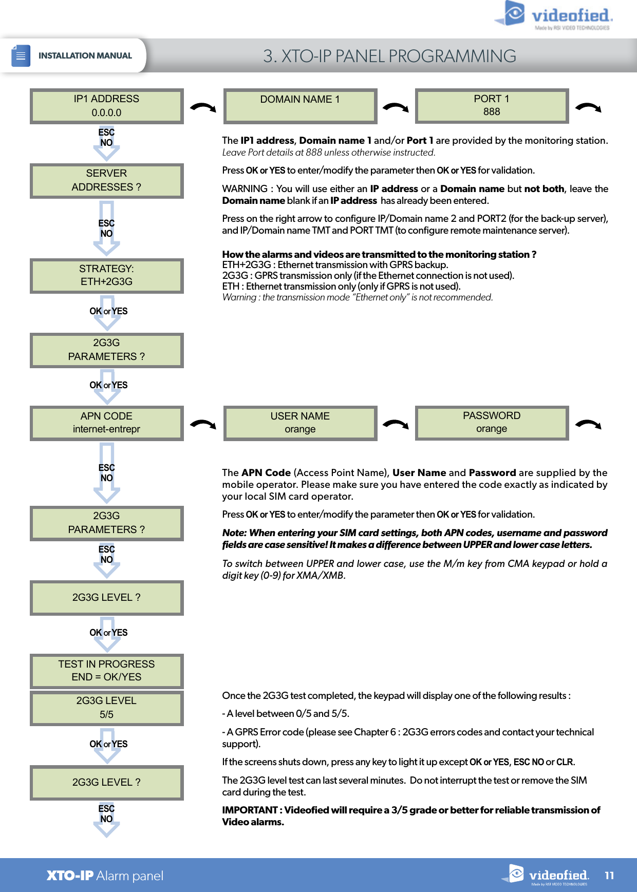
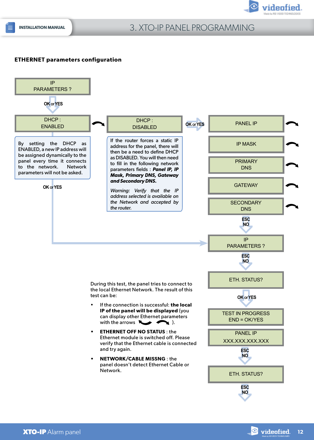
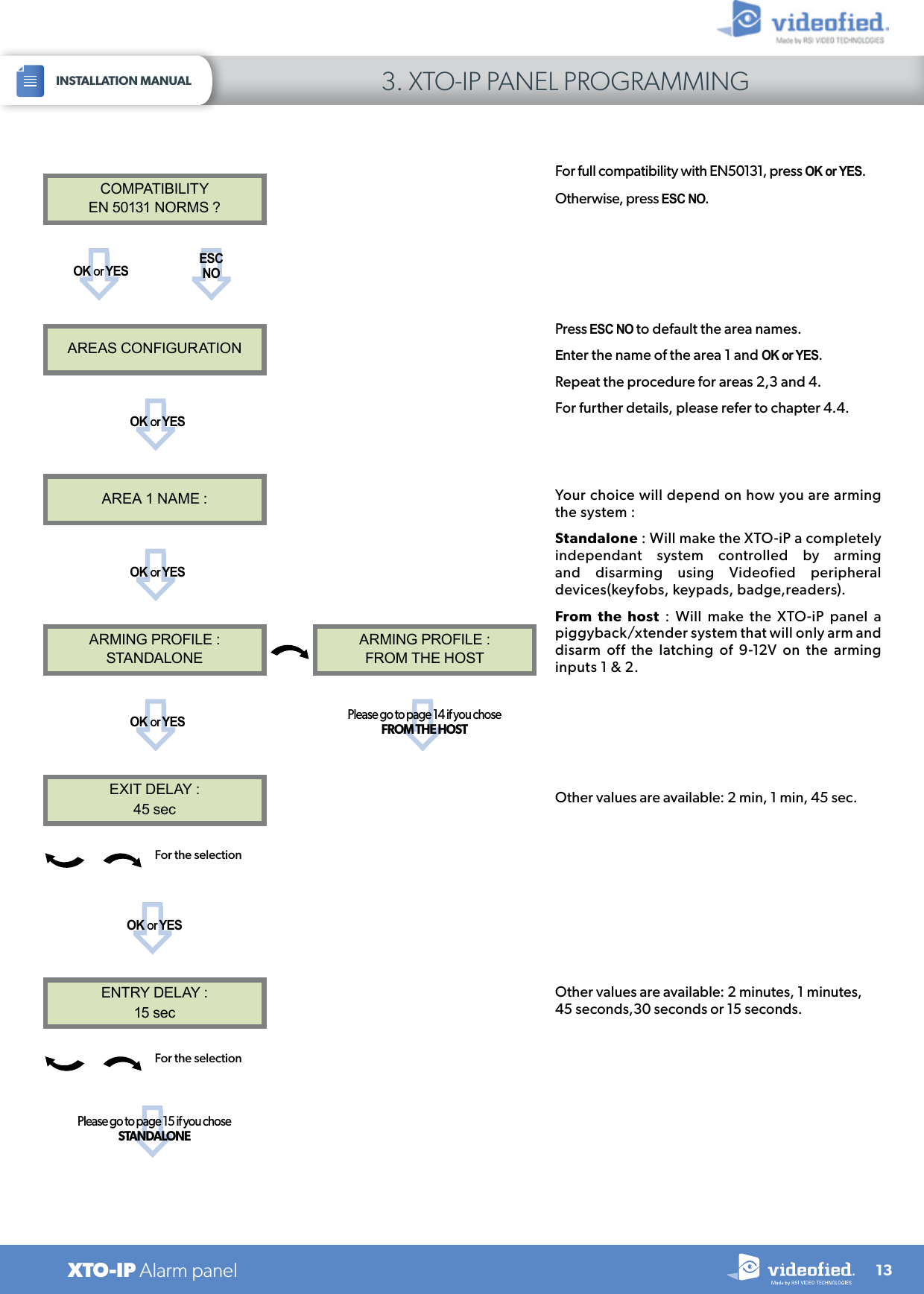
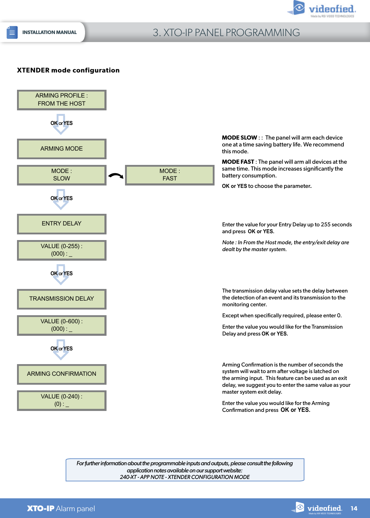
![4.9 Golden rules1 Area 1 is always delayed.When you register a keypad or a badge reader into an area, that area will automatically be delayed. 2 Never position a panel next to a high voltage electrical cabinet .3 Press CLR to erase a typing mistake.4 Never register the same device twice (delete from the system first).5 Registration of up to 25 devices (including the keypad).6 Respect indoor infrared devices installation height (2m10 to 2m30).7 Outdoor cameras have to be installed at 2m60 to 3 meters height. Those devices needs to to protect an access and not a zone.8 Do not fix the keypad at the beginning of the installation as it will need to be portable during programming. Always clean the lens of the cameras aer the installation (Use a clean, dry cloth, taking care not to exert pressure on the lens).910 To switch between UPPER and lower case, use the M/m key from the CMA keypad or hold a digit key (0 to 9) for XMA/XMB.11 Internal components are fragile, be careful opening or closing the panel. LCD screen goes dark aer 30 seconds of inactivity, press an arrow or numeric key to light it up.13 Use only batteries provided by Videofied (siren : Alkaline batteries). 14 Infrared detectors should never be installed in stairs or close to stairs (false alarm risks).15 A colon display [:] means that the parameter can be changed.1223INSTALLATION MANUAL 4. XTO-IP FEATURES GUIDEXTO-IP Alarm panel](https://usermanual.wiki/RSI-VIDEOTECHNOLOGIES/XT06/User-Guide-2922211-Page-23.png)