RTX X8660 DECT 6.0 Base Station User Manual
RTX Hong Kong Ltd. DECT 6.0 Base Station
UserManual.wiki
>
RTX
>
X8660 User Manual
>
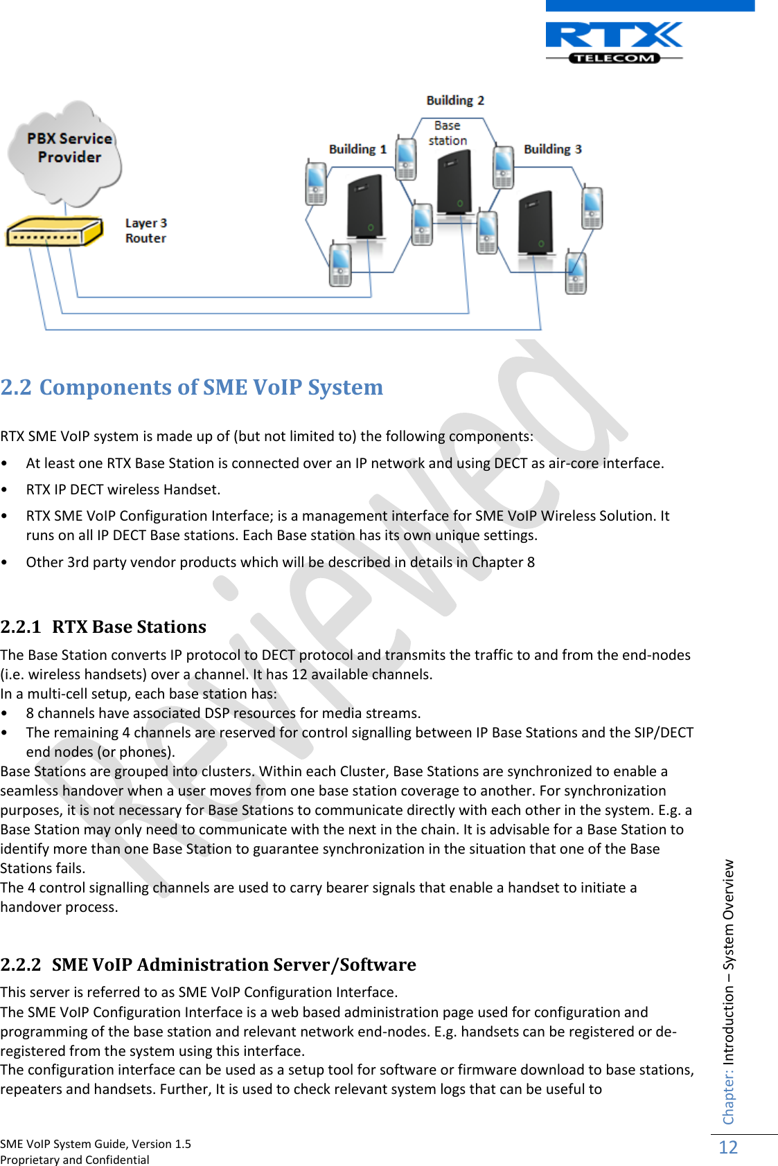
user manual
Contents
1.
user manual
2.
user manual safety instructions
3.
user manual statements
user manual
Navigation menu
Upload a User Manual
Namespaces
Wiki Guide
HTML
PDF
Info
Views
User Manual
Discussion / Help
Navigation
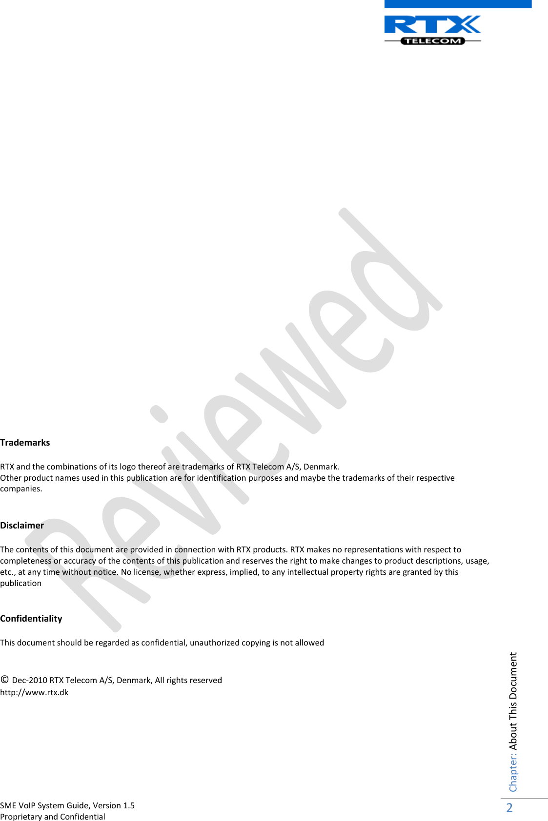

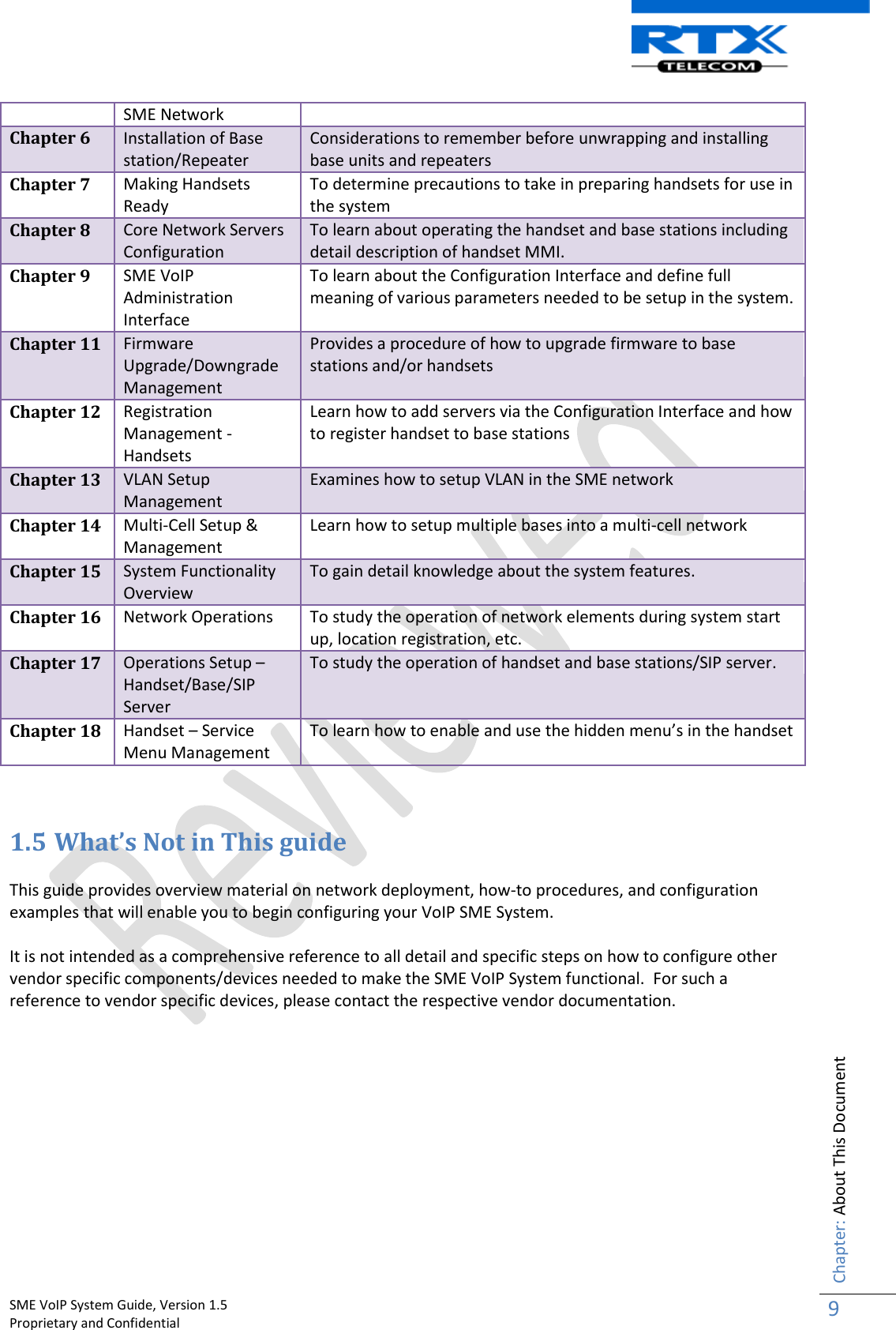
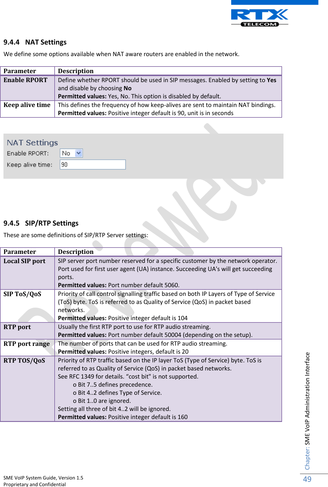
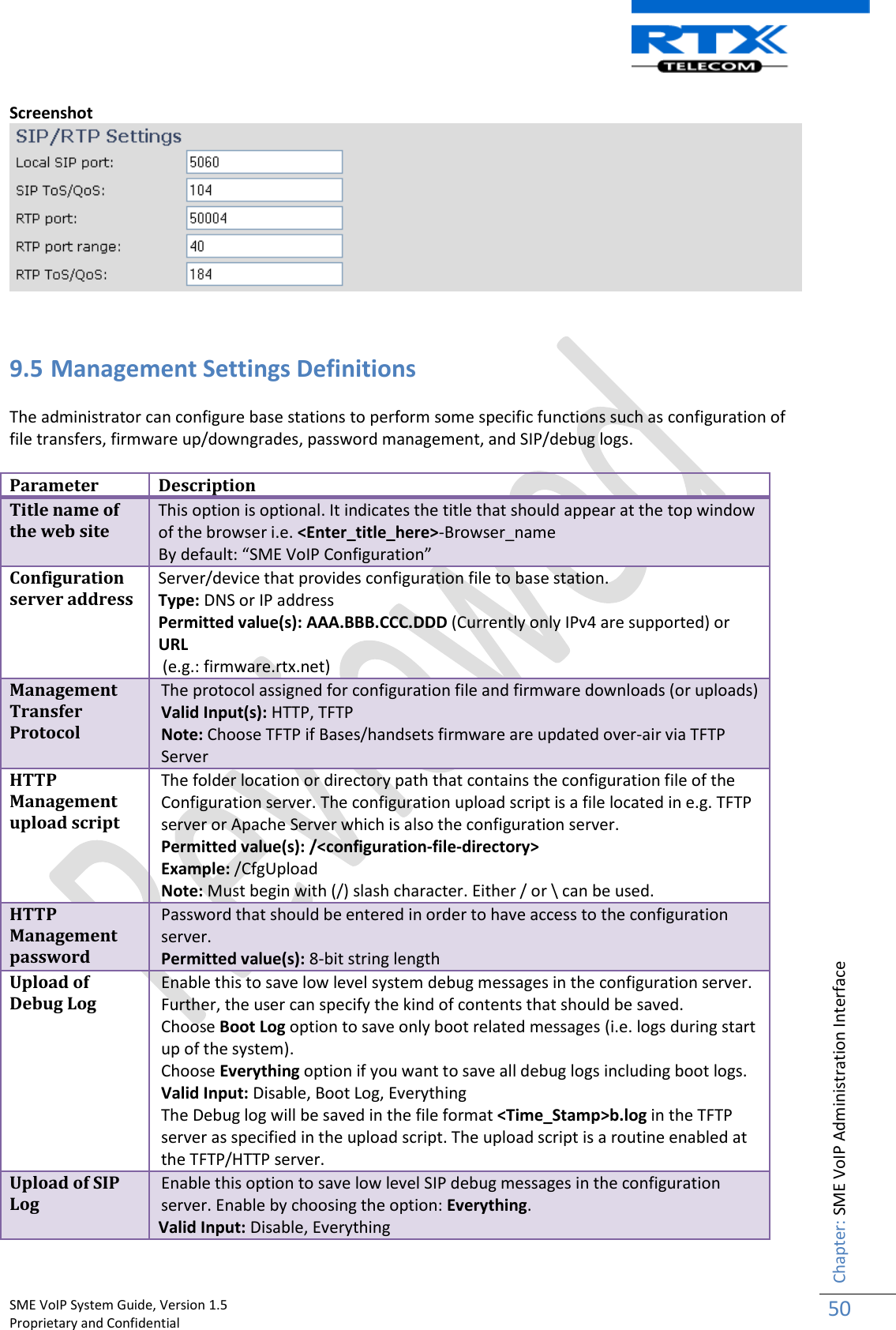
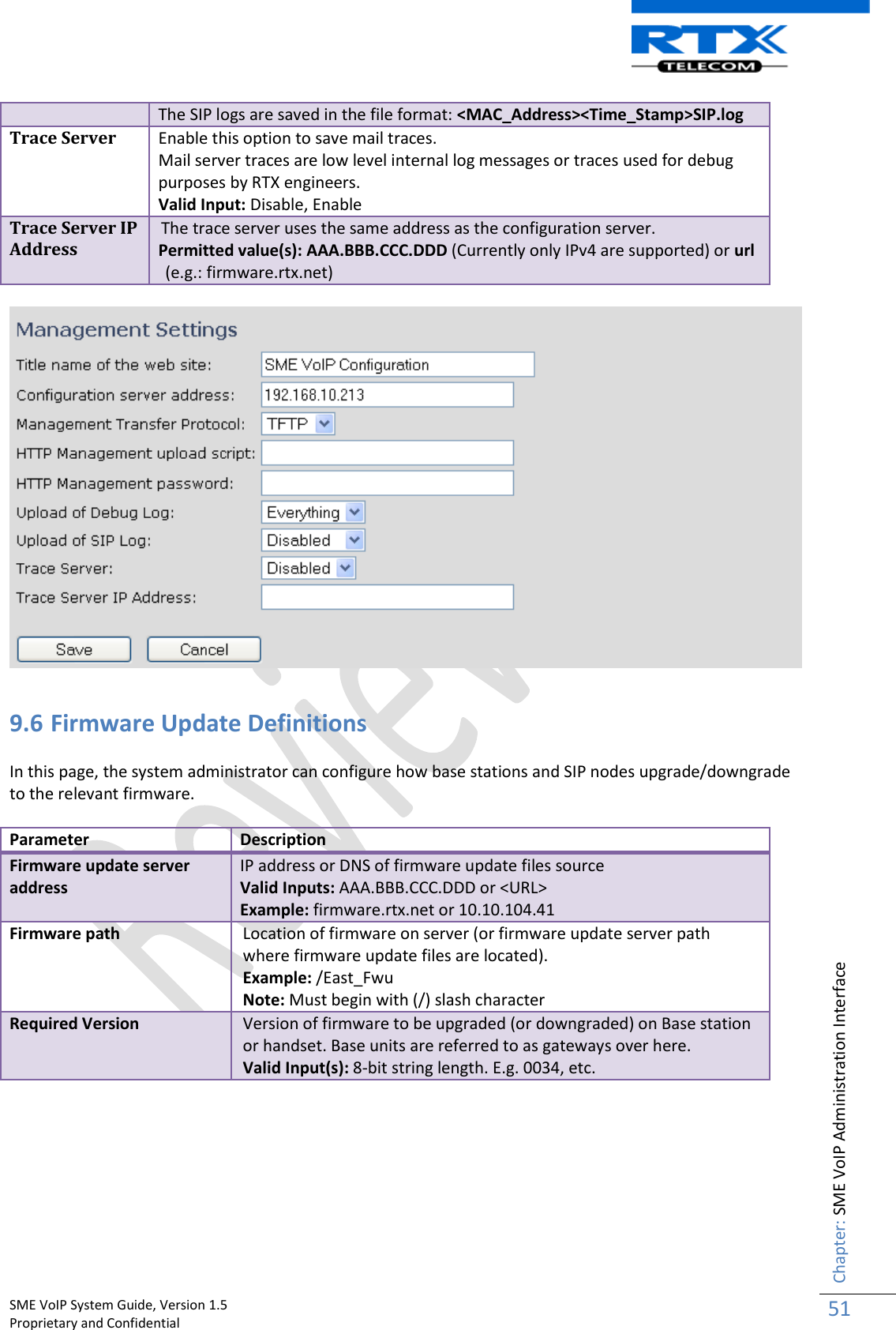
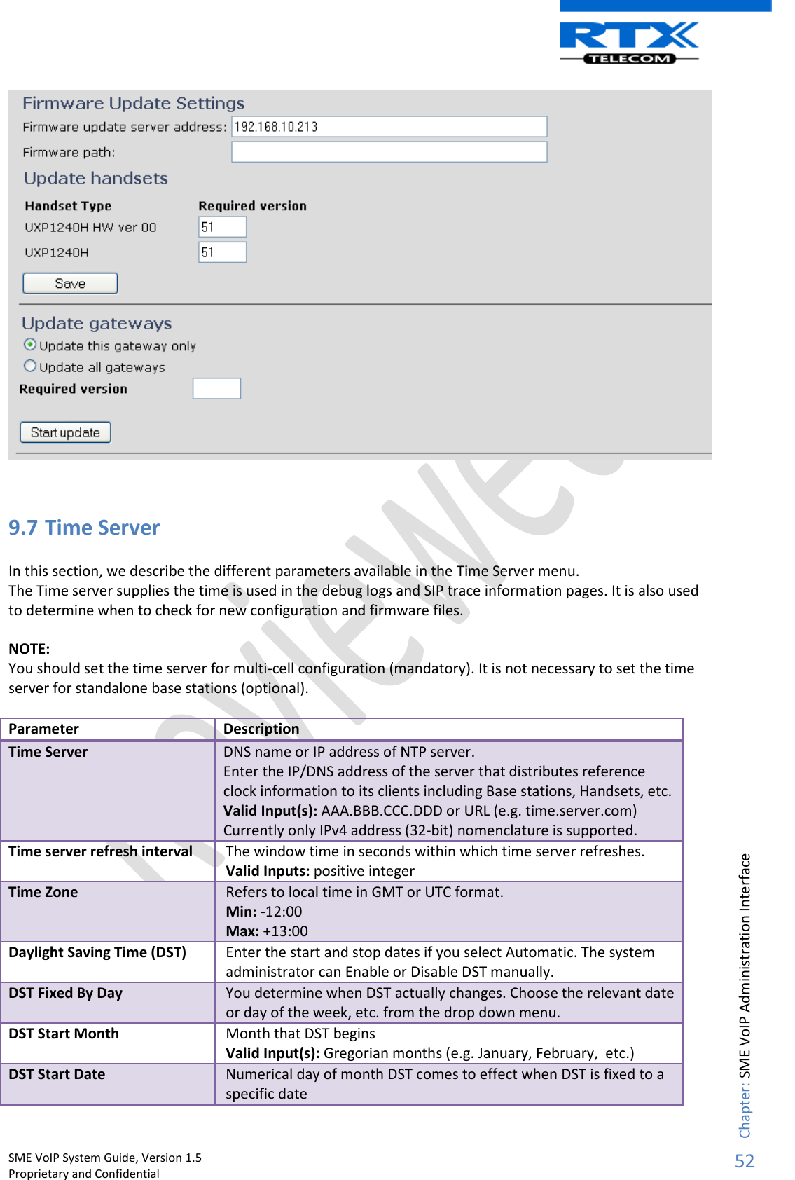
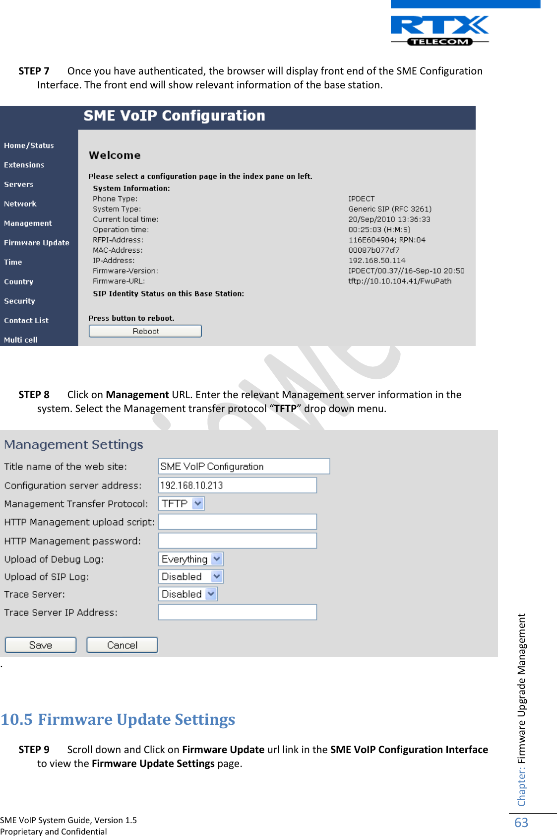
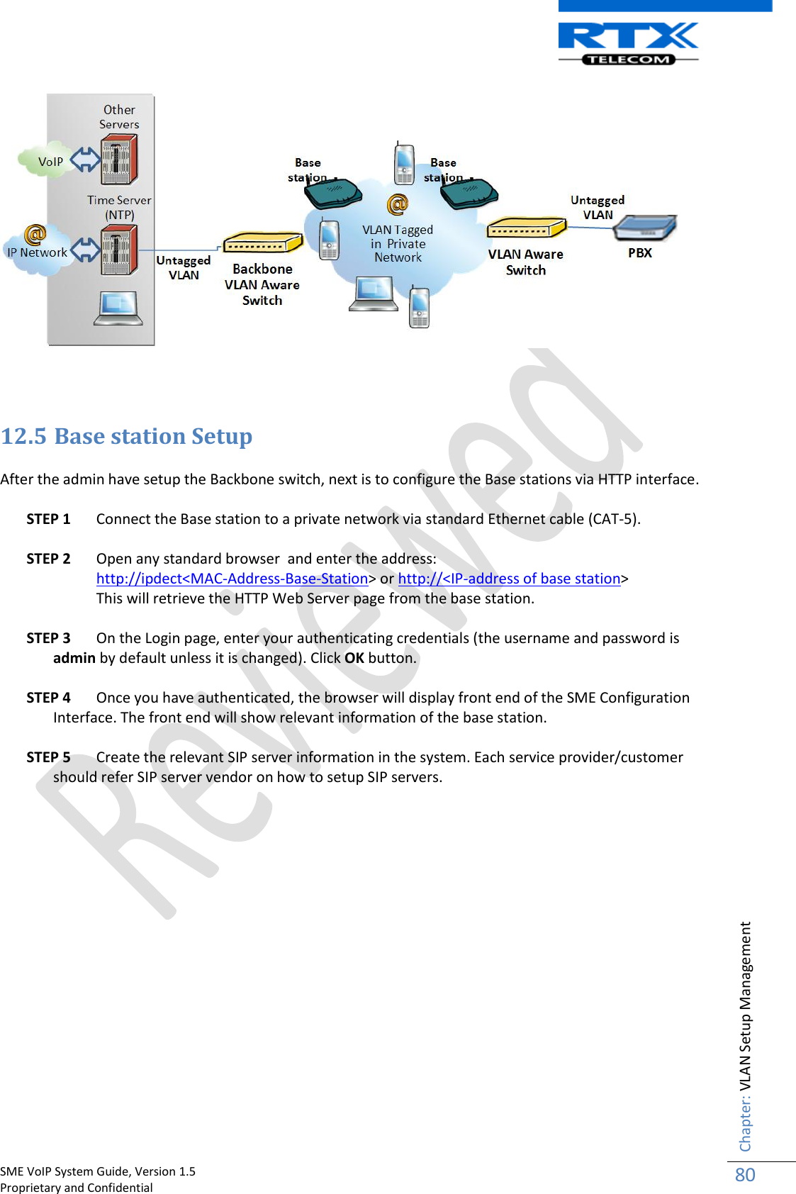
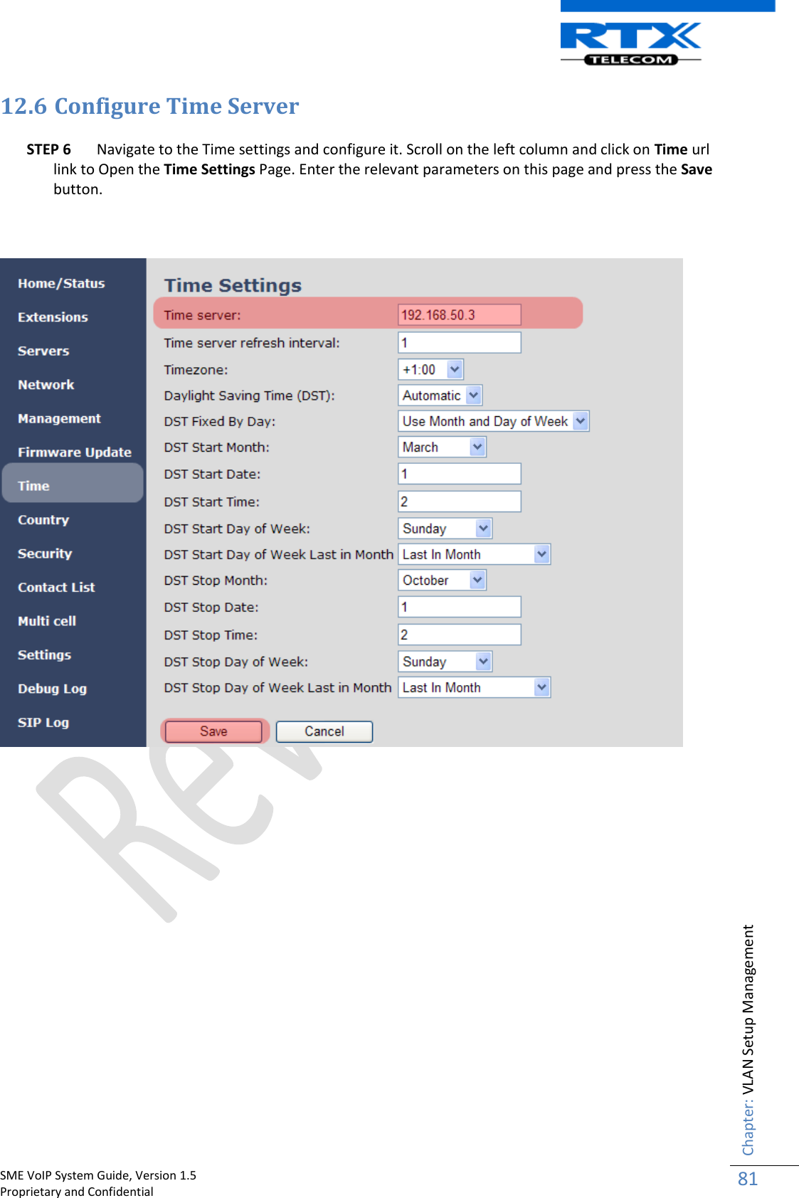
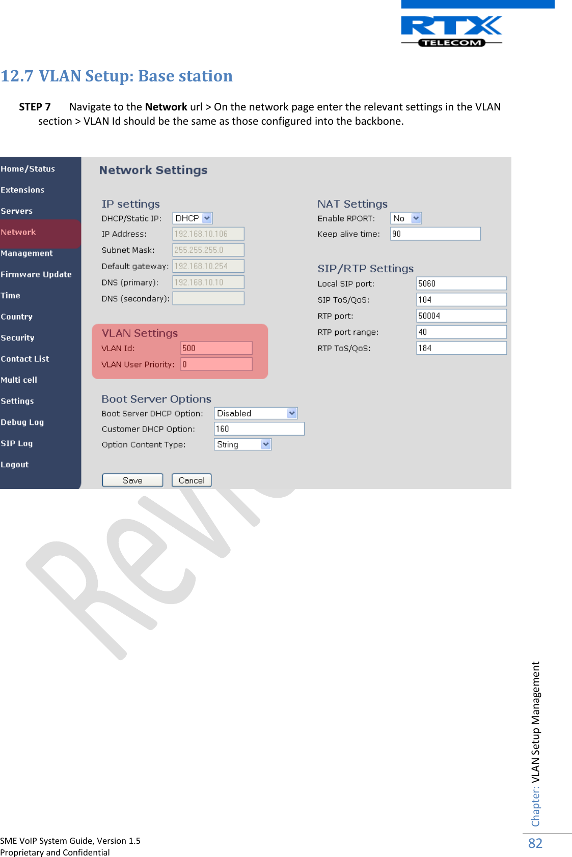
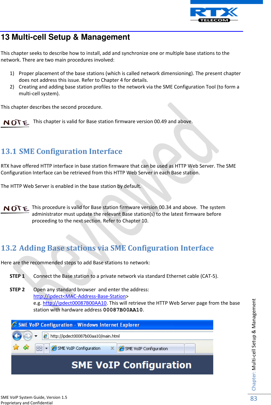
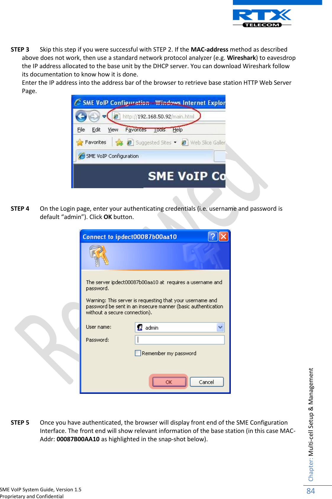
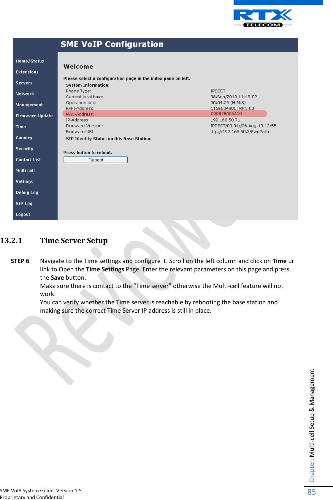
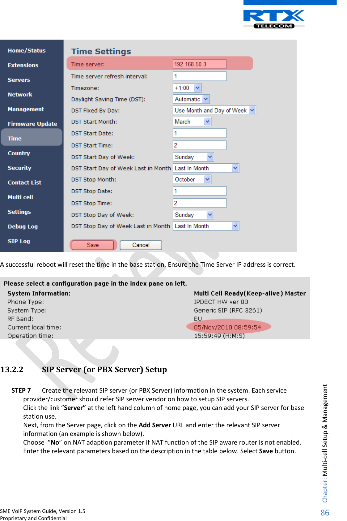
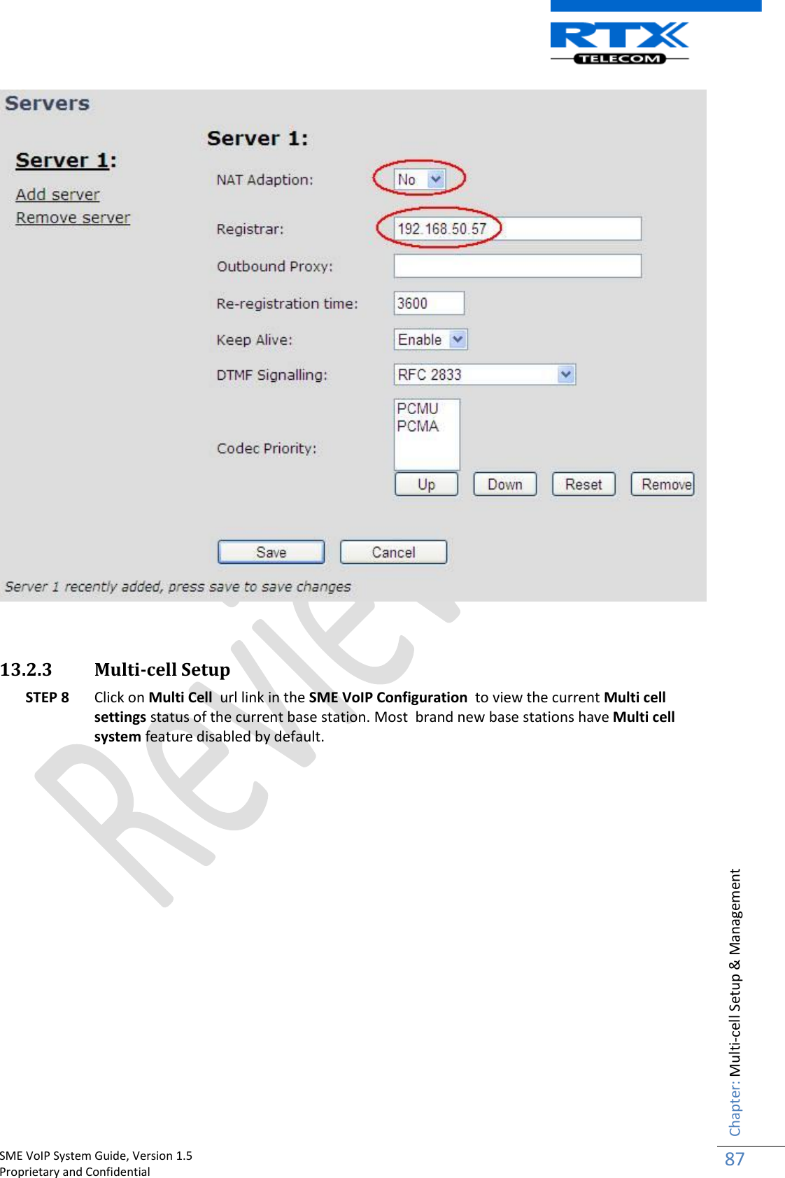
![SME VoIP System Guide, Version 1.5 Proprietary and Confidential Chapter: About This Document 10 1.6 Abbreviations For the purpose of this document, the following abbreviations hold: DHCP: Dynamic Host Configuration Protocol DNS: Domain Name Server HTTP(S): Hyper Text Transfer Protocol (Secure) (T)FTP: (Trivial) File Transfer Protocol IOS: Internetworking Operating System PCMA: A-law Pulse Code Modulation PCMU: mu-law Pulse Code Modulation PoE: Power over Ethernet RTP: Real-time Transport Protocol RPORT: Response Port (Refer to RFC3581 for details) SIP: Session Initiation Protocol SME: Small and Medium scale Enterprise VLAN: Virtual Local Access Network TOS: Type of Service (policy based routing) URL: Uniform Resource Locator UA: User Agent 1.7 References/Related Documentation [1]: Deployment Kit Guide Version 2.5 [2]: Hosted PBX Solution - Deployment Kit Version 0.5 [3]: Handset operation Manual V0.1 [4]: 1.8 Document History Revision Author Issue Date Comments 1.5 MYA 17-Dec-2010 Complete review and modifications of all sections 1.4 MYA 12-Nov-2010 New Input: 17.3 Call Operations, Operations Setup – Handset/Base/SIP Server. 1.1 MYA 27-Oct-2010 Total re-write of overall of manual 1.0 MYA 05-Oct-2010 First version, SIP version, EU DECT 0.1 MYA 23-Sep-2010 Initial Version 1.9 Documentation Feedback We always strive to produce the best and we also value your comments and suggestions about our documentation. If you have any comments about this guide, please enter them through the Feedback link on the RTX Telecom website. We will use your feedback to improve the documentation.](https://usermanual.wiki/RTX/X8660.user-manual/User-Guide-1420656-Page-10.png)
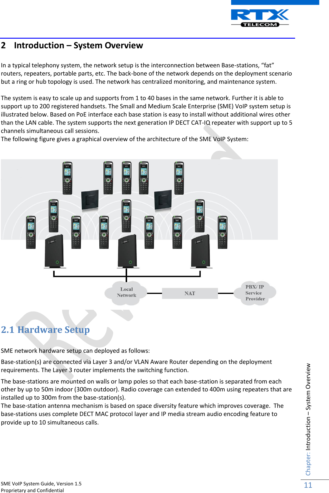
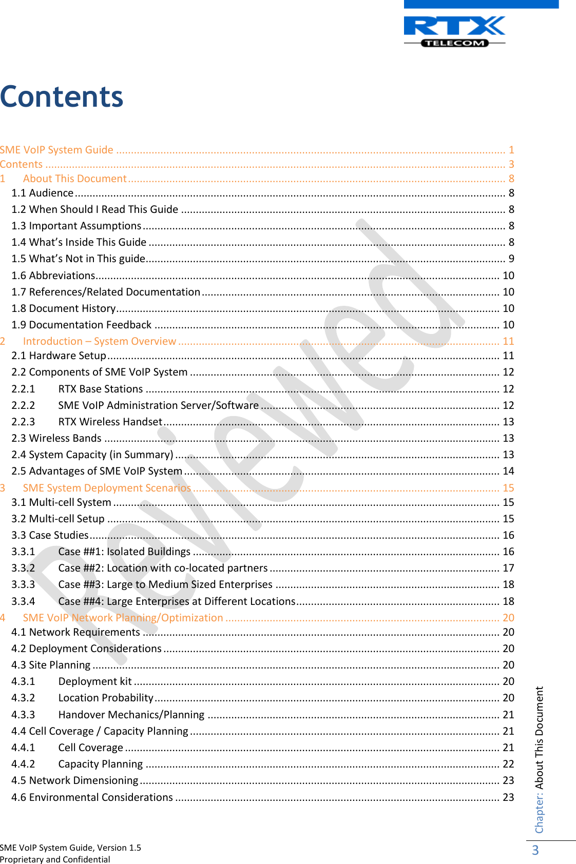
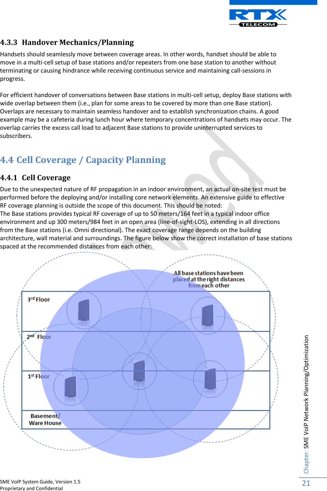
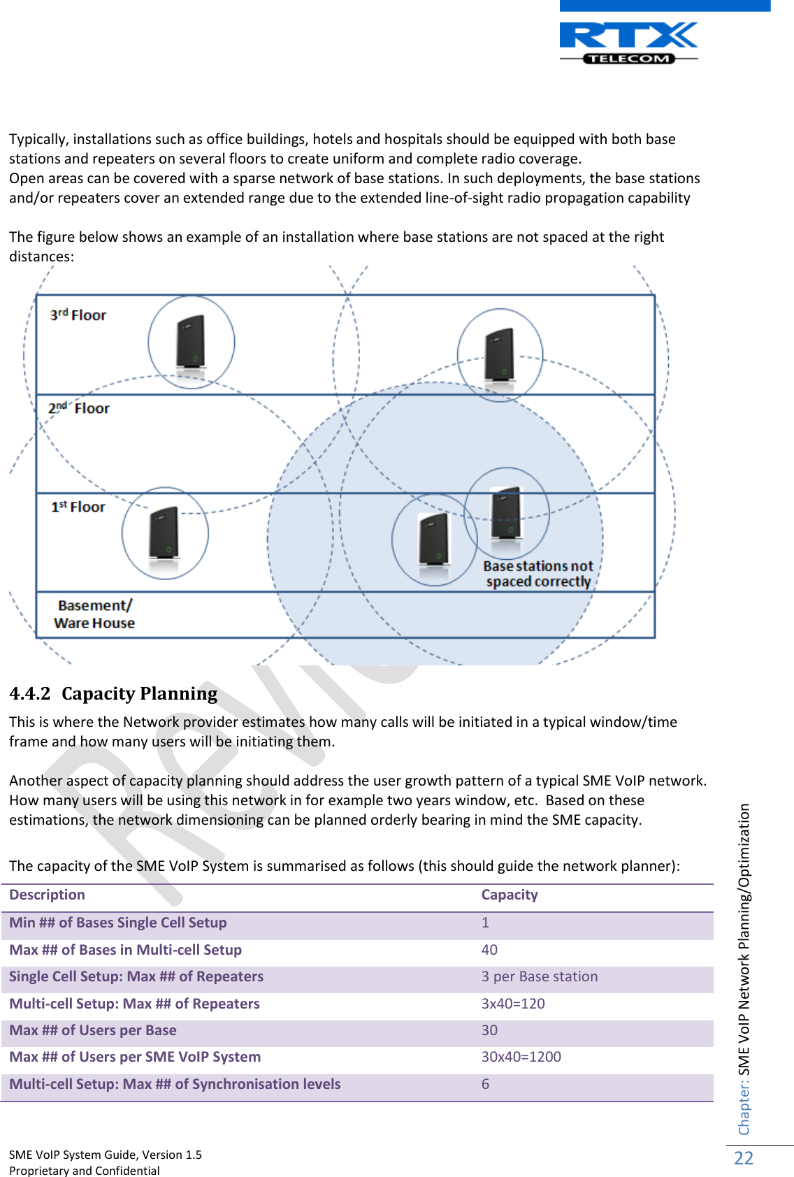
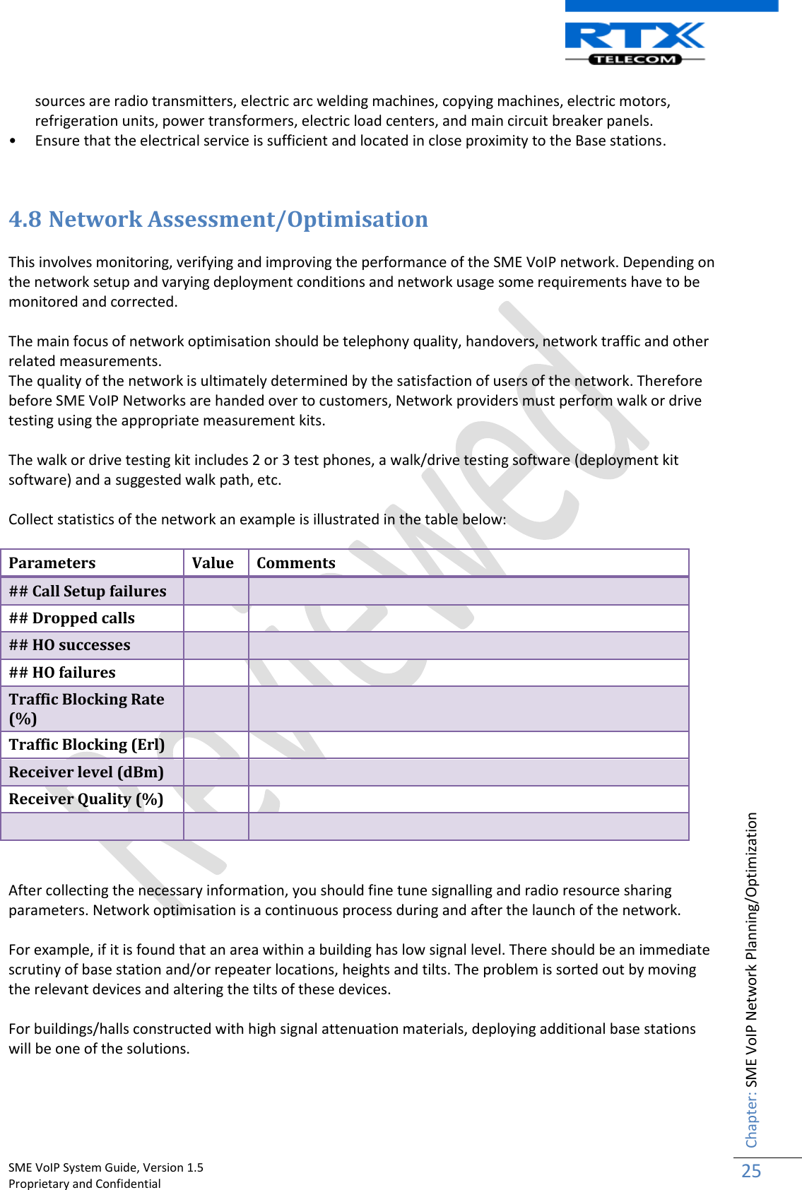
![SME VoIP System Guide, Version 1.5 Proprietary and Confidential Chapter: SME VoIP Network Planning/Optimization 20 4 SME VoIP Network Planning/Optimization In this chapter, we describe SME VoIP radio network planning techniques including dimensioning, detailed capacity and coverage planning, and network optimisation. 4.1 Network Requirements Network requirement is essential to determine elements necessary to achieve the overall expectations of the customer. Typical network requirements includes (but not limited to): The geographical area to be covered The type or architecture of building and/or topology, etc. The estimated traffic on each zone or region or building The blocking criteria in each traffic area. The relevant quality targets expected to be achieved 4.2 Deployment Considerations The following radio considerations must be examined before deploying a SME VoIP System. These includes (but not limited to): Building Penetration: When a signal strikes a building it is diffracted or absorbed; therefore to some extend the signal is reduced. The amount of absorption is dependent of the kind of building and its environment, the amount of solid structure. This is an important consideration in coverage planning. Interference Sources: Signals to receiving antenna can be weakened by virtue of interference from other signals. These signals may be from the same network or other man-made objects. Interference sources must be identified and avoided or minimized. 4.3 Site Planning 4.3.1 Deployment kit Based on propagation models, the coverage of areas is done with the use of radio planning tools. In the RTX SME VoIP Network, the radio planning tool available is called Deployment Kit. Detail description and use of this document is available in a separate document(s) [1][2]. 4.3.2 Location Probability The quality of coverage is determined by location probability. For practical purposes, the location probability of 50% is equal to the sensitivity of receiver in a specific region. This is also measured by the Deployment Kit [1][2].](https://usermanual.wiki/RTX/X8660.user-manual/User-Guide-1420656-Page-20.png)
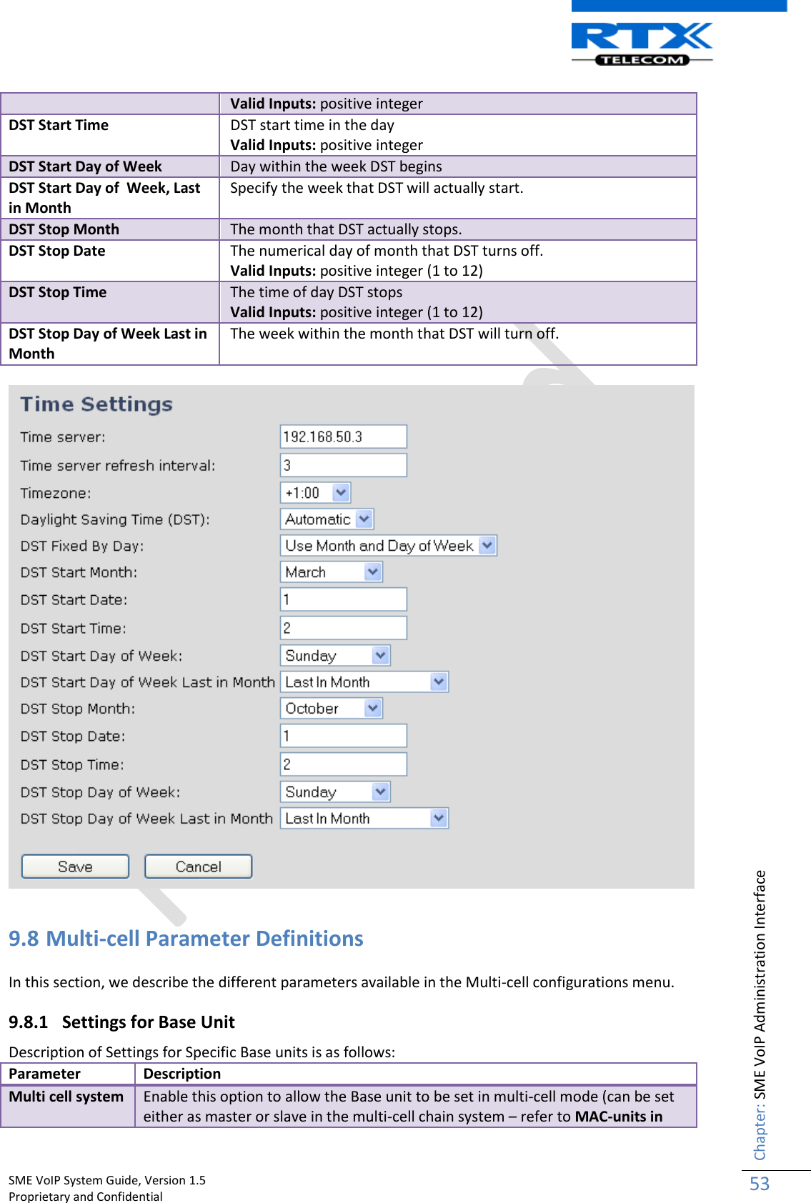
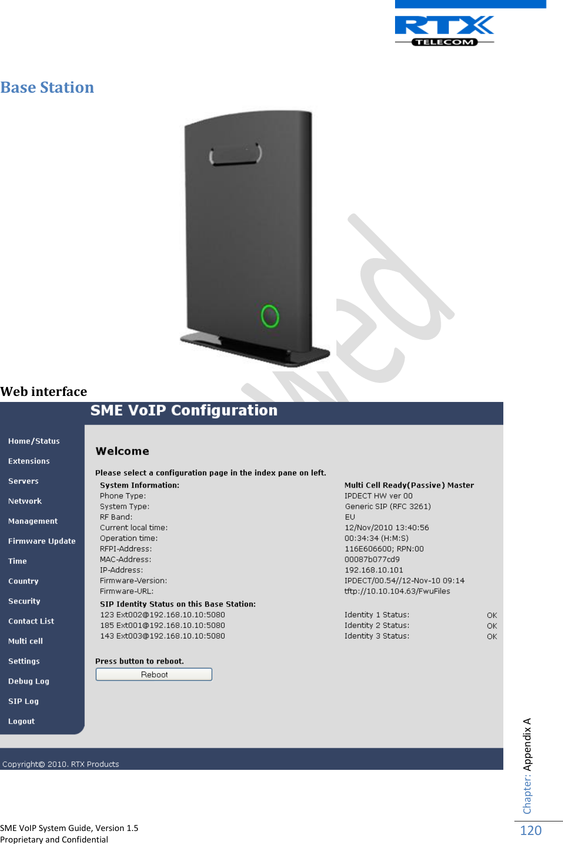
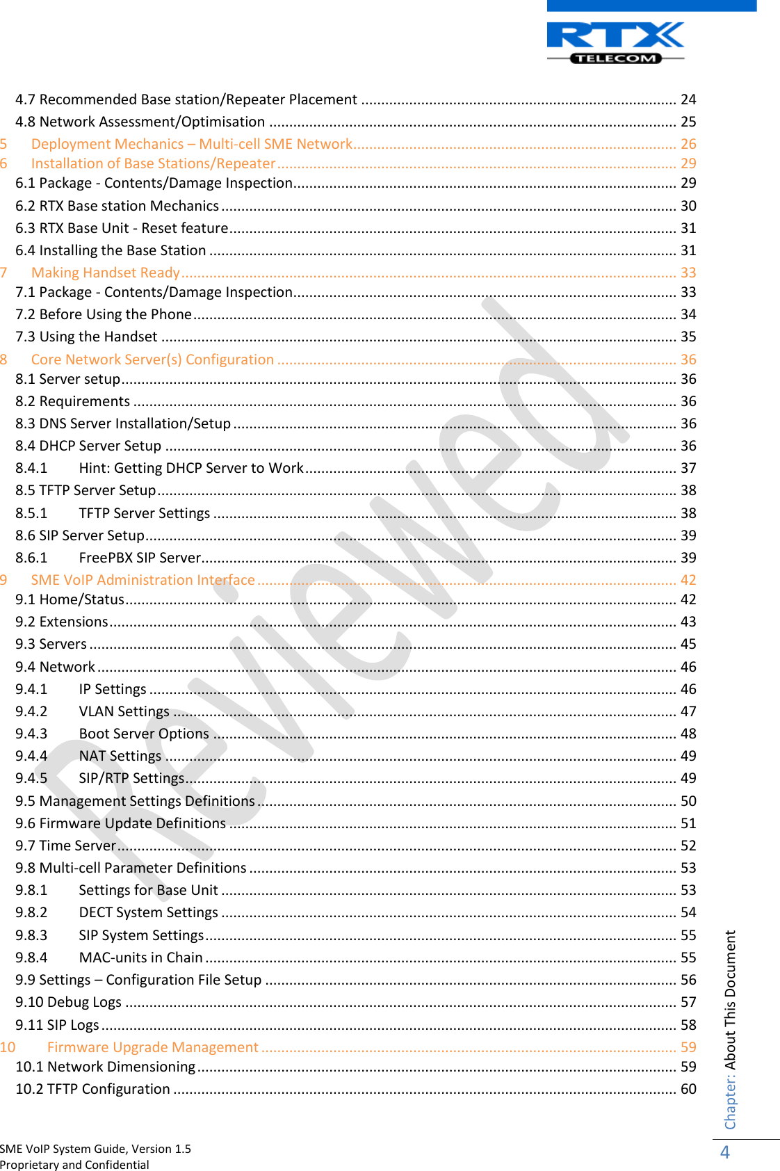
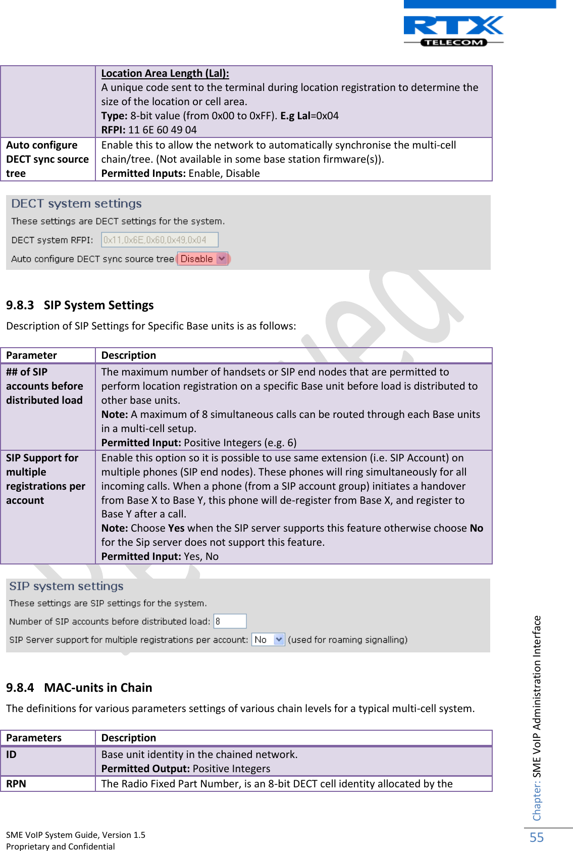
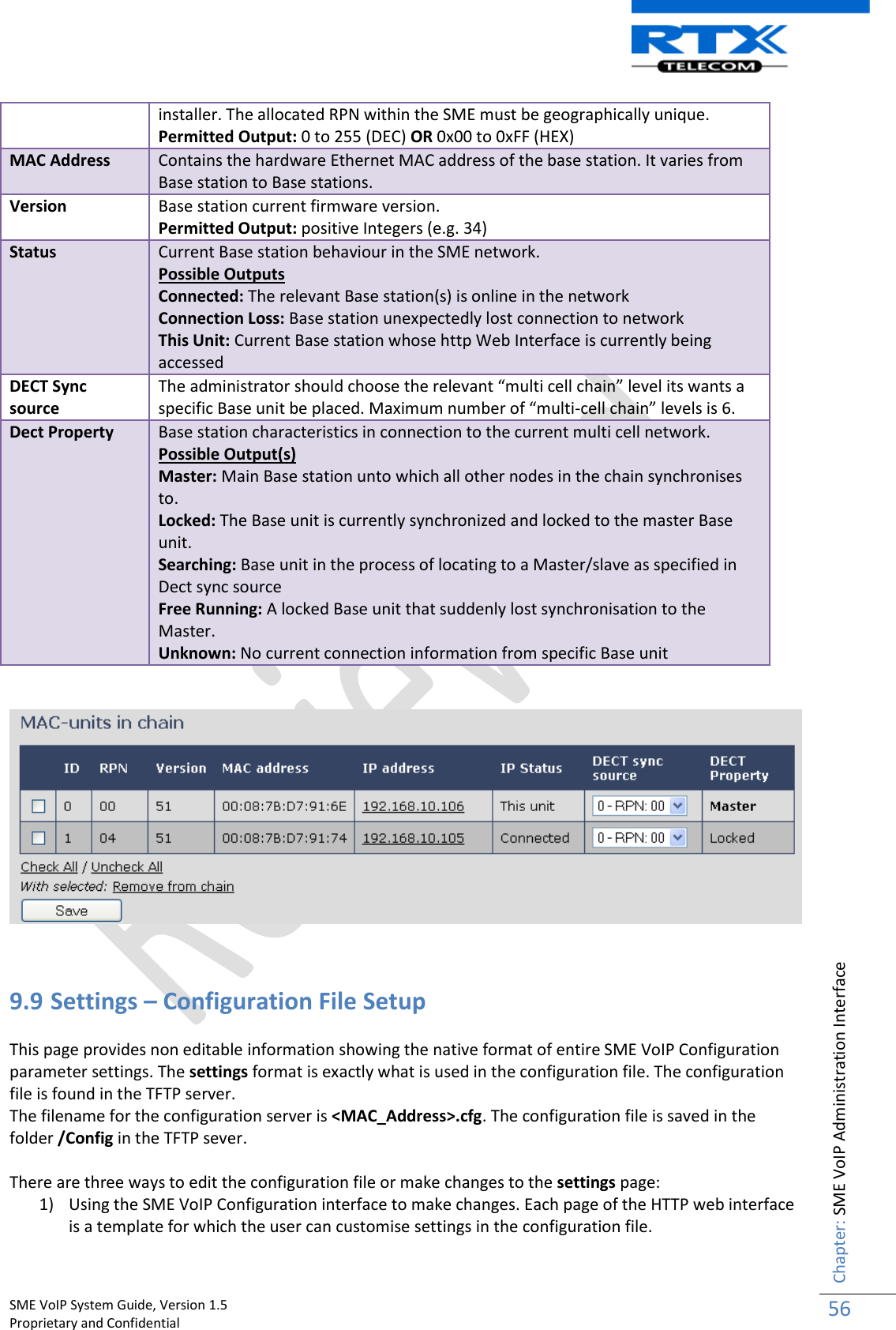
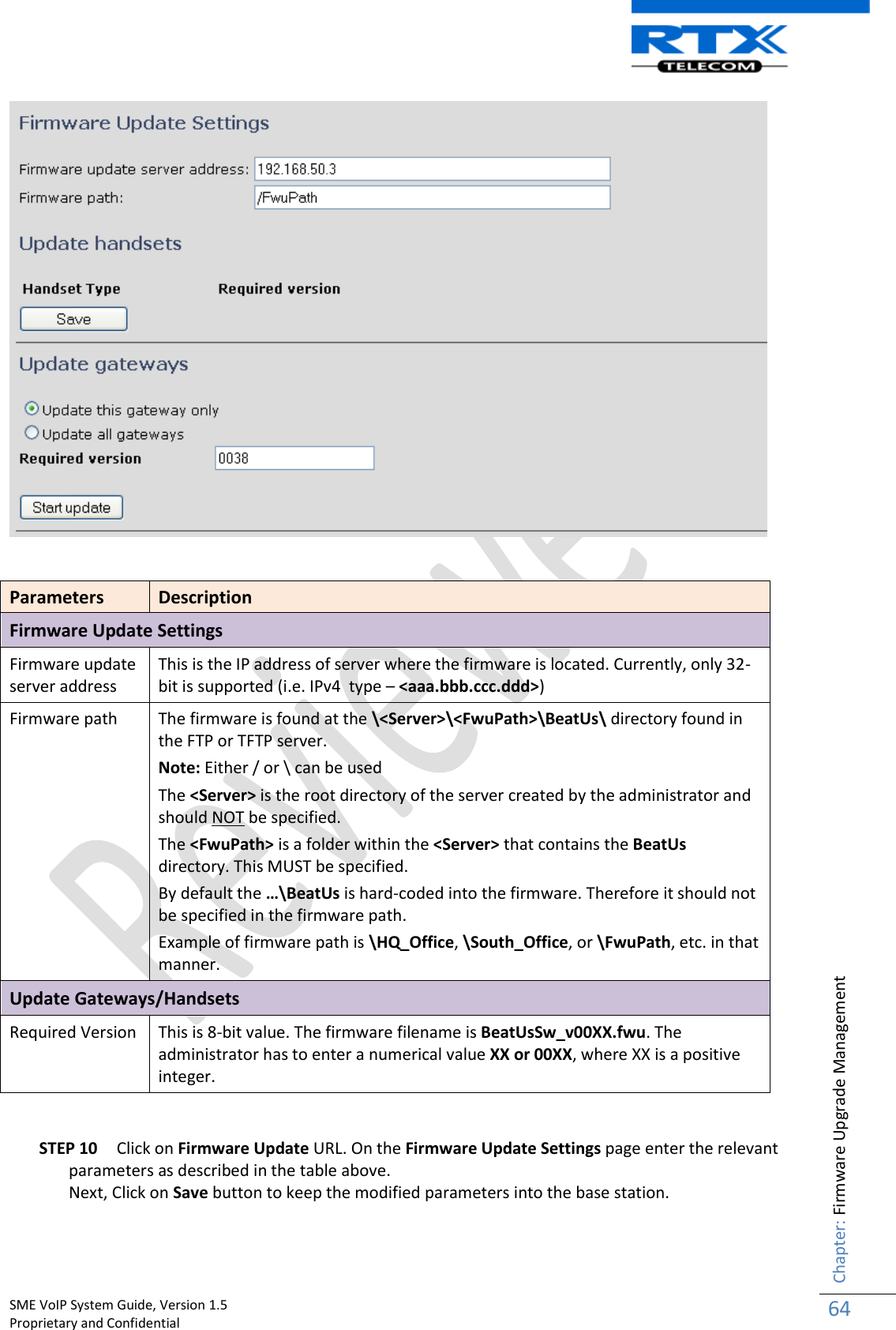
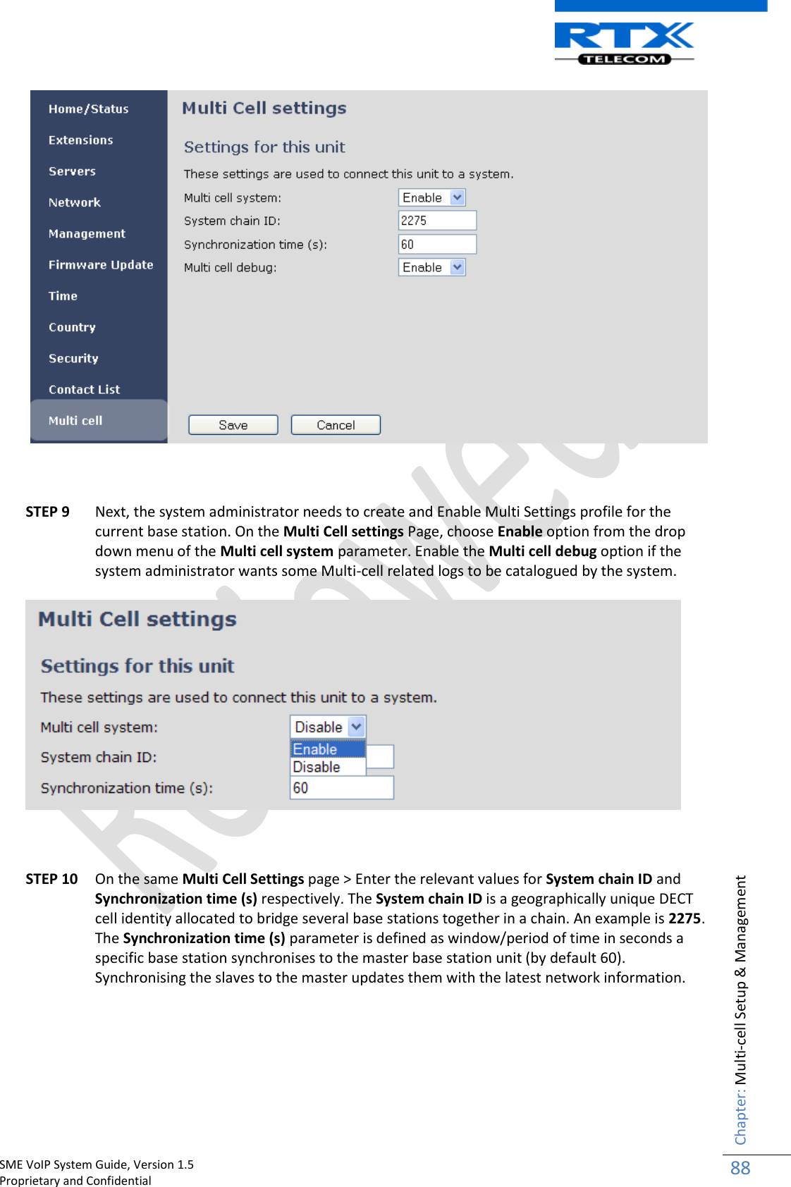
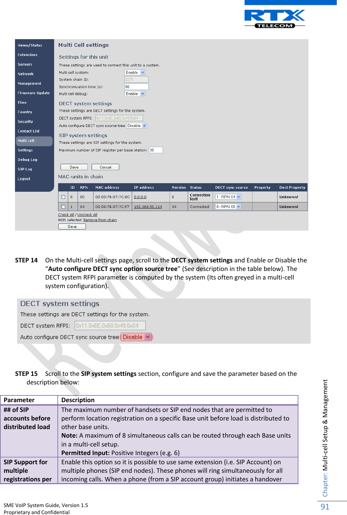
![SME VoIP System Guide, Version 1.5 Proprietary and Confidential Chapter: SME VoIP Administration Interface 54 Chain section for details). Valid Inputs: Enable, Disable System chain ID This is an identifier (in string format e.g. 2275) that is unique for a specific multi-cell system. Note: There can be several multi-cell systems in SME network. Up to 7 levels of base stations chains are permitted in a typical setup. Please refer to accompanied document [2] for further details and description. Valid Input: 16 bit String length Synchronization time (s) This specifies the period in seconds when elements/nodes (e.g. Base units) in a specific Multi-cell should synchronise to each other. Multi cell debug Enable this feature, if you want the system to catalogue low level multi-cell debug information or traces. 9.8.2 DECT System Settings Description of DECT Settings for Specific Base units is as follows: Parameter Description DECT system RFPI This is a radio network identity accessed by all Base units in a specific multi-cell system. It composed of 5 octets. It is actually 5 different variables combined together. RFPI Format: XX XX XX XX XX (where XX are HEX values) Note: Only type e.g. 11 6E 60 49 04 the system reformats as 0x11 0x6E 0x60 0x49 0x04 Access Rights Class (ARC): Defines network identity structure used by terminals especially in multi-cell environment. Fixed/default Value=1 (Private multi-cell system). RFPI: 1X XX XX XX XX Equipment Installer's code (EIC): Code that allows terminals to distinguish between separate DECT networks. Example_RTX_EIC: 0x16E6 (May change in the future) RFPI: 11 6E 6X XX XX Fixed Part Number(FPN): Is a geographically unique identity transmitted to DECT networks to help PP distinguish between base station communications in different cells/multi-cell systems. E.g. FPN: 0x049 RFPI: 11 6E 60 49 XX](https://usermanual.wiki/RTX/X8660.user-manual/User-Guide-1420656-Page-54.png)
:DHCP Enabled 0101000013 [N](01):IP Address: 192.168.10.101 0101000013 [N](01):Gateway Address: 192.168.10.254 0101000013 [N](01):Subnet Mask: 255.255.255.0 0101000013 [N](01):TFTP boot server not set by DHCP. Using Static. 0101000013 [N](01):DHCP Discover completed 0101000013 [N](01):Time Server: 192.168.10.11 0101000013 [N](01):Boot server: 10.10.104.63 path: Config/ Type: TFTP 0101000013 [N](01):RemCfg: Download request of Config/00087b077cd9.cfg from 10.10.104.63 using TFTP 0101000014 [N](01):accept called from task 7 0101000014 [N](01):TrelAccept success [4]. Listening on port 10010 0101000019 [N](01):RemCfg: Download request of Config/00087b077cd9.cfg from 10.10.104.63 using TFTP 0101000019 [W](01):Load of Config/00087b077cd9.cfg from 10.10.104.63 failed](https://usermanual.wiki/RTX/X8660.user-manual/User-Guide-1420656-Page-57.png)
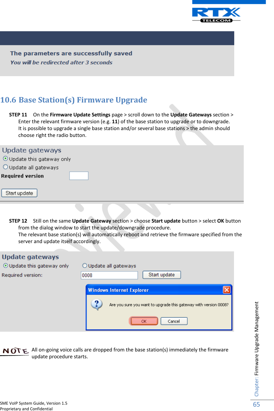

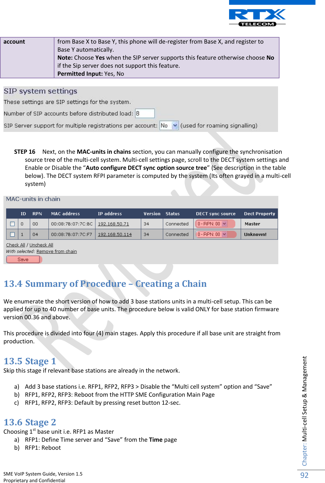
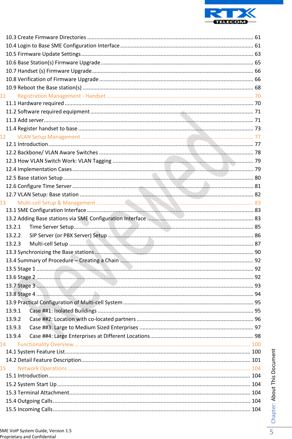
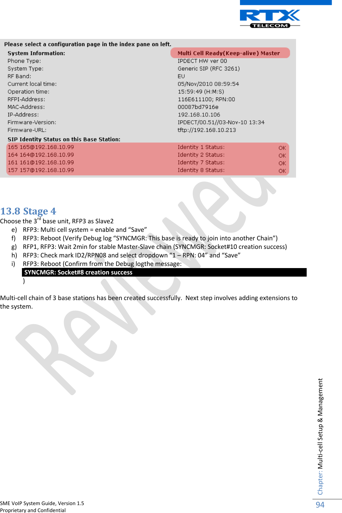
![SME VoIP System Guide, Version 1.5 Proprietary and Confidential Chapter: Multi-cell Setup & Management 93 c) RFP1: Press “Add server” and define SIP server IP and “Save” from the Servers page d) RFP1: Multi cell system = enable and “Save” from the Multi-cell page e) RFP1: Reboot (Verify the message: “SYNCMGR: This base is ready to be master in a Chain” From the debug logs) 13.7 Stage 3 Choose another base unit,RFP2 as Slave1 a) RFP2: Multi cell system = enable and “Save” b) RFP2: Reboot (Verify from Debug log “SYNCMGR: This base is ready to join into another Chain”) c) RFP1, RFP2: Wait 2min for stable Master-Slave chain (check for the message: SYNCMGR: Socket#10 creation success from the debug log) d) After a successful restart, on each base [RFP1 and RFP2] Multi-cell page you will find the other base connected and synchronized (the IP status shows This Unit or Connected) to the system as illustrated below. You can register an arbitrary HS to the extension and verify whether its successful from the “Home” page and Handset UI](https://usermanual.wiki/RTX/X8660.user-manual/User-Guide-1420656-Page-93.png)
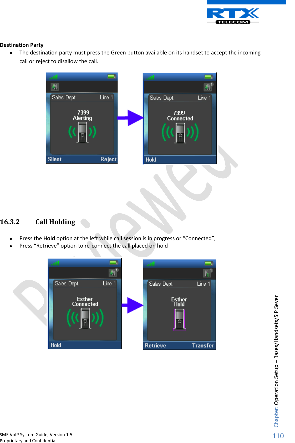
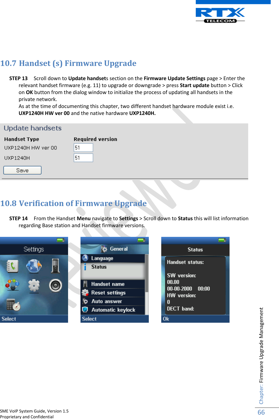
![SME VoIP System Guide, Version 1.5 Proprietary and Confidential Chapter: Operation Setup – Bases/Handsets/SIP Sever 109 16.3 Call Operations In this section we describe call procedures in the SME VoIP system. We will narrow our description to call transfer and call conference. Please view accompanied document for detail description of Handset operations [3]. Some Definitions There are three actors in a given transfer event, each playing one of the following roles: Transferee: the party being transferred to the Transfer Target. Transferor: the party initiating the transfer Transfer Target: the new party being introduced into a call with the Transferee. The following roles are used to describe transfer requirements and scenarios: 1. Originator - wishes to place a call to the Recipient. This actor is the source of the first INVITE in a session, to a Facilitator or a Screener. 2. Facilitator - receives a call or out-of-band request from the Originator, establishes a call to the Recipient through the Screener, and connects the Originator to the Recipient. 3. Screener - receives a call ultimately intended for the Recipient and transfers the calling party to the Recipient if appropriate. 4. Recipient - the party the Originator is ultimately connected to. Call Transfer - Requirements Any party in a call session is able to transfer any other party in that session at any point in that session. The Transferor and the Transferee are not removed from a session as part of a transfer transaction. This requirement is needed so e.g. ring-back on transfer failure will not be lost. The Transferor is aware of whether or not the transfer was successful 16.3.1 Initiating Calls Enter Number Press Green Button to start dialling Originating Party](https://usermanual.wiki/RTX/X8660.user-manual/User-Guide-1420656-Page-109.png)