RTX X8663 DECT Base station User Manual
RTX Hong Kong Ltd. DECT Base station Users Manual
UserManual.wiki
>
RTX
>
X8663 User Manual
Users Manual
Navigation menu
Upload a User Manual
Namespaces
Wiki Guide
HTML
PDF
Info
Views
User Manual
Discussion / Help
Navigation
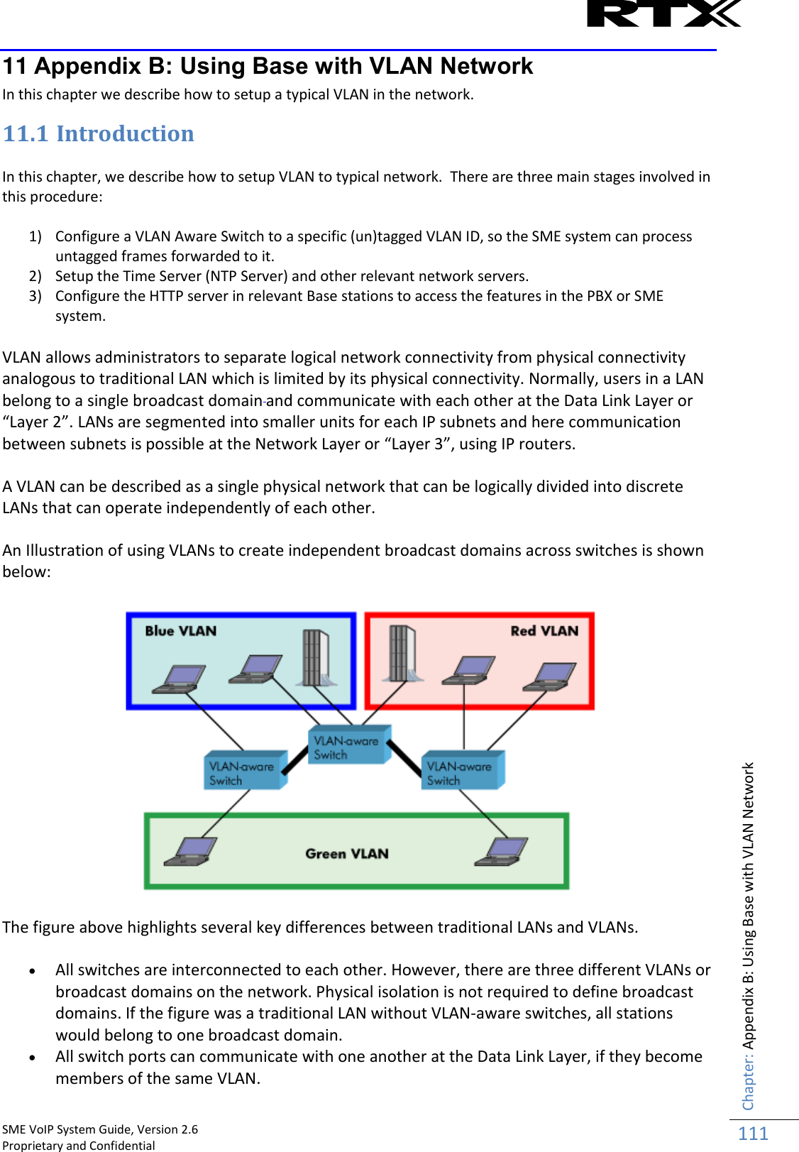
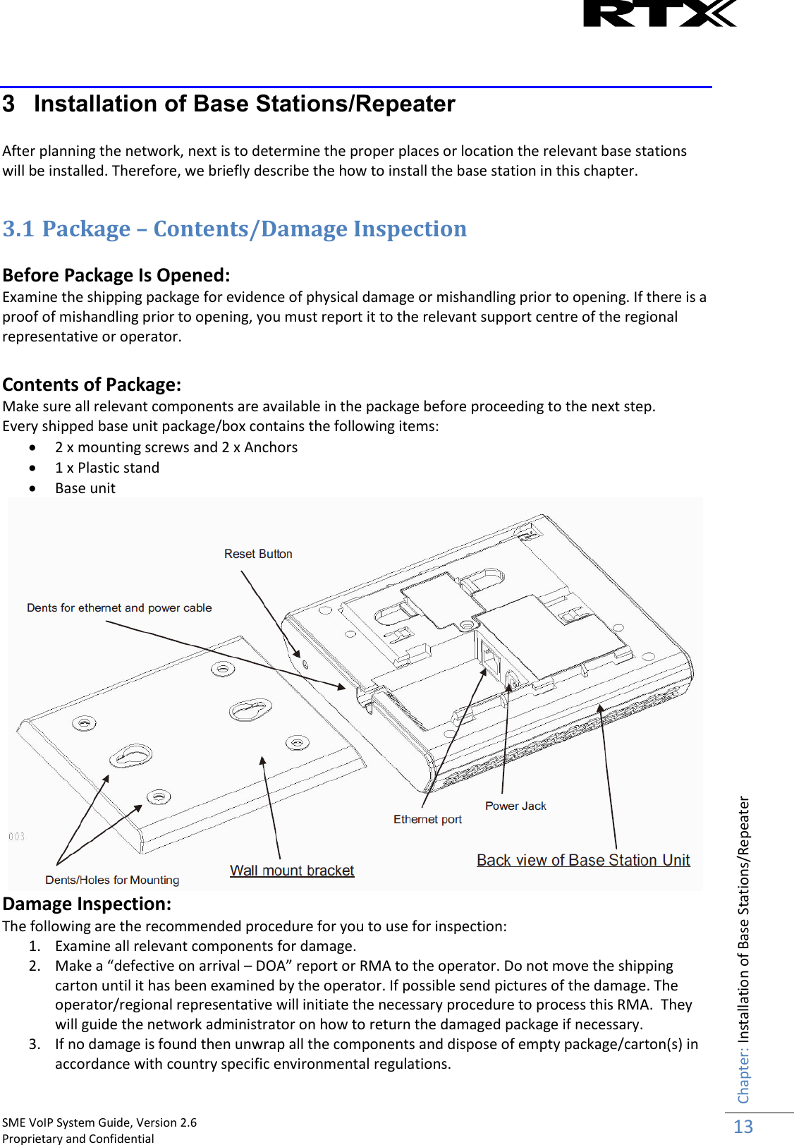
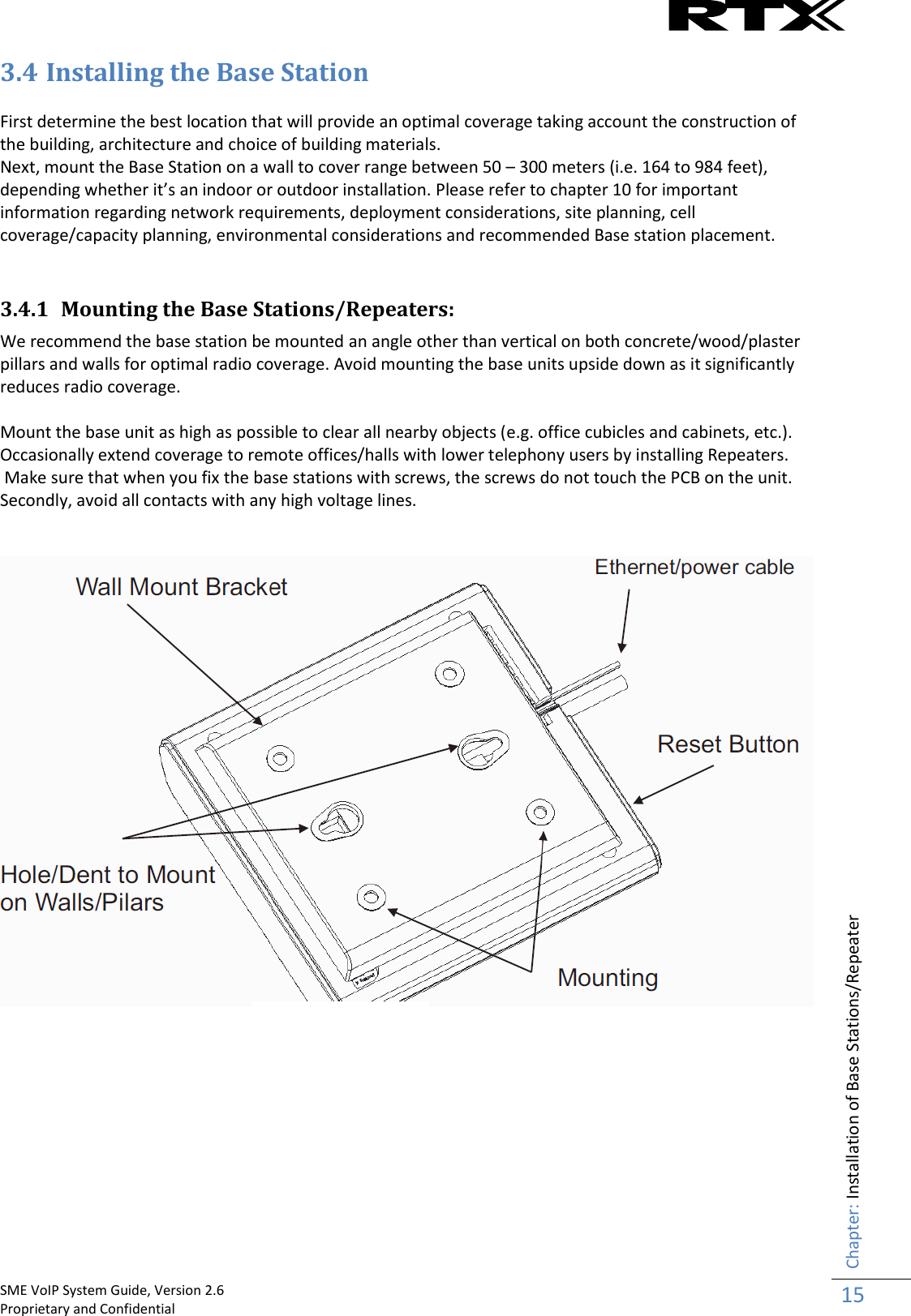
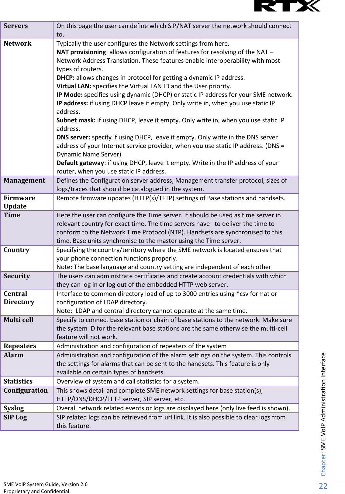
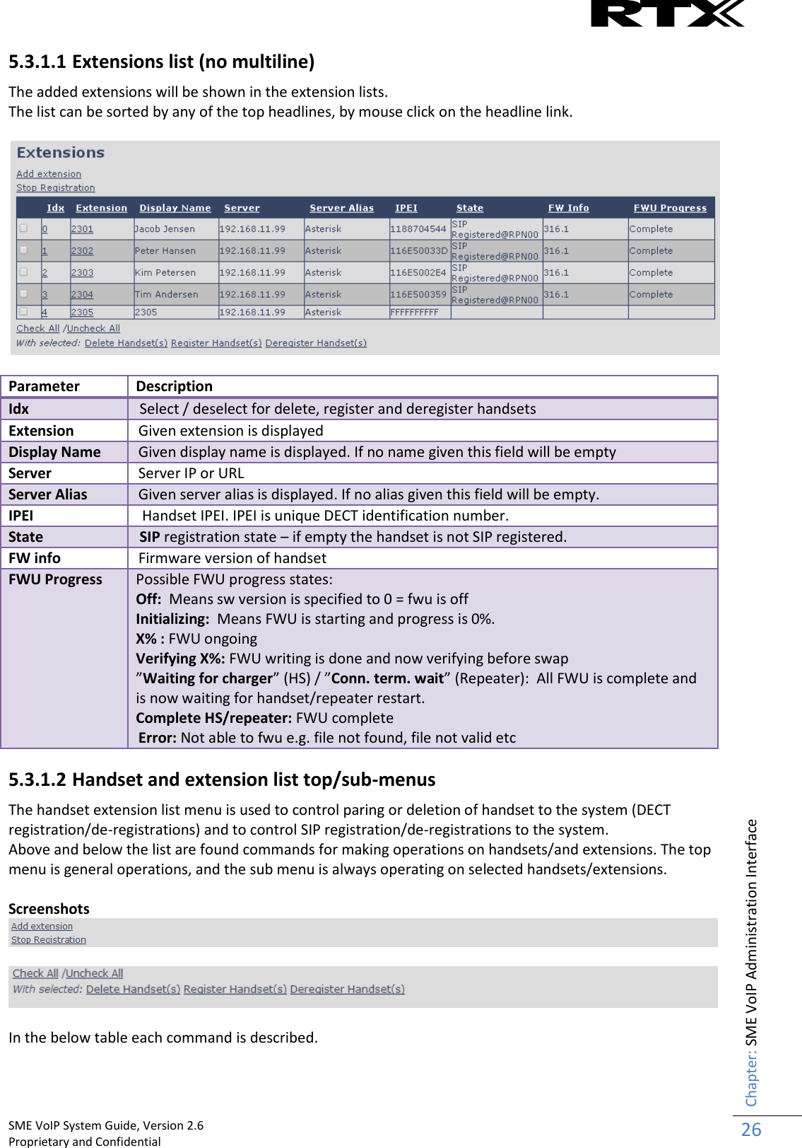
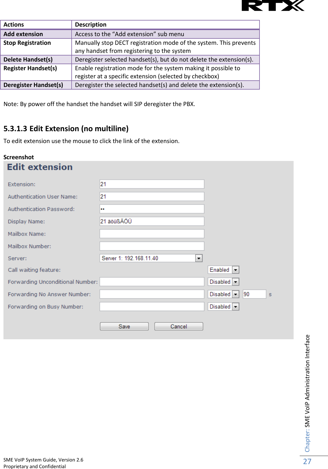
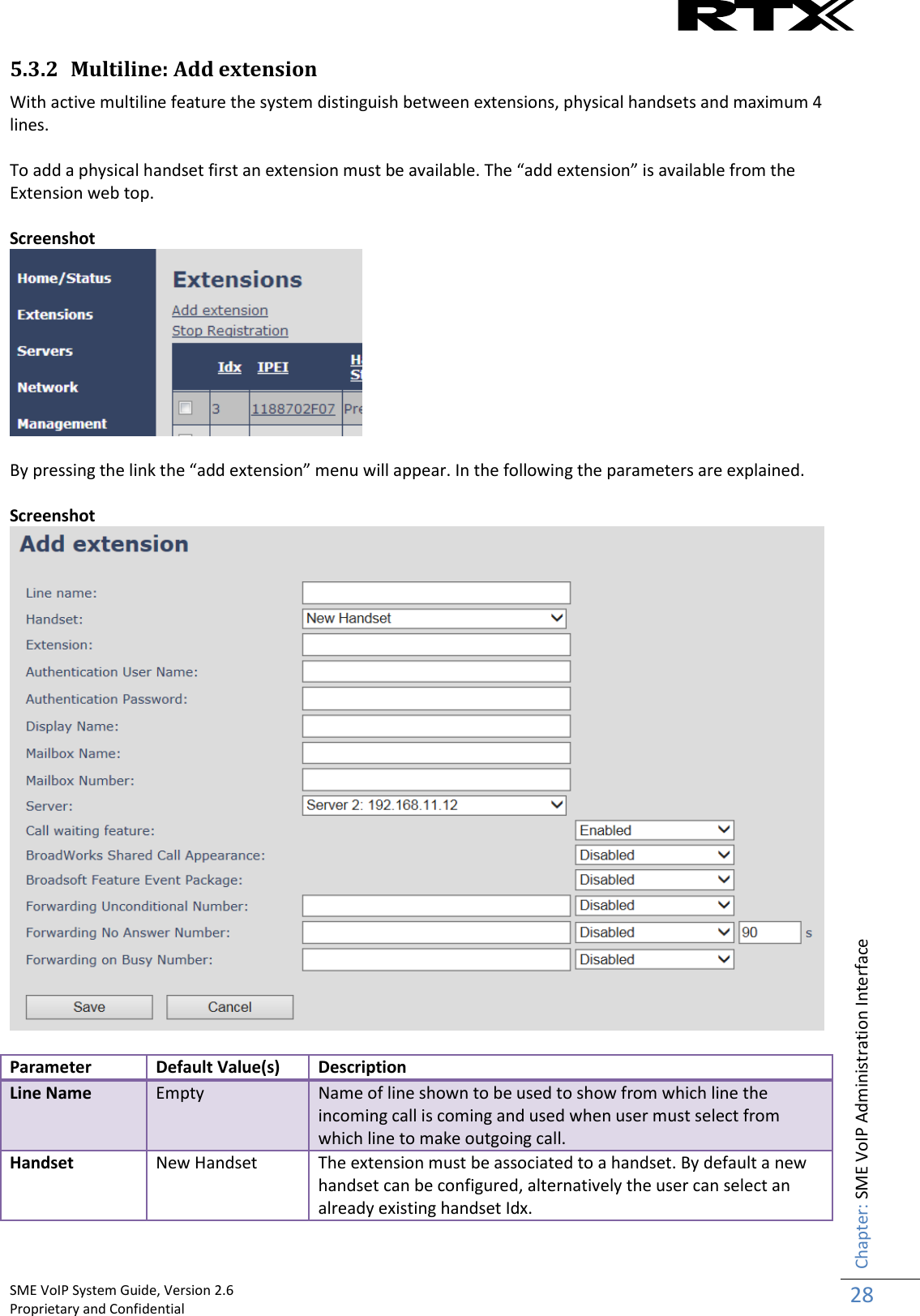
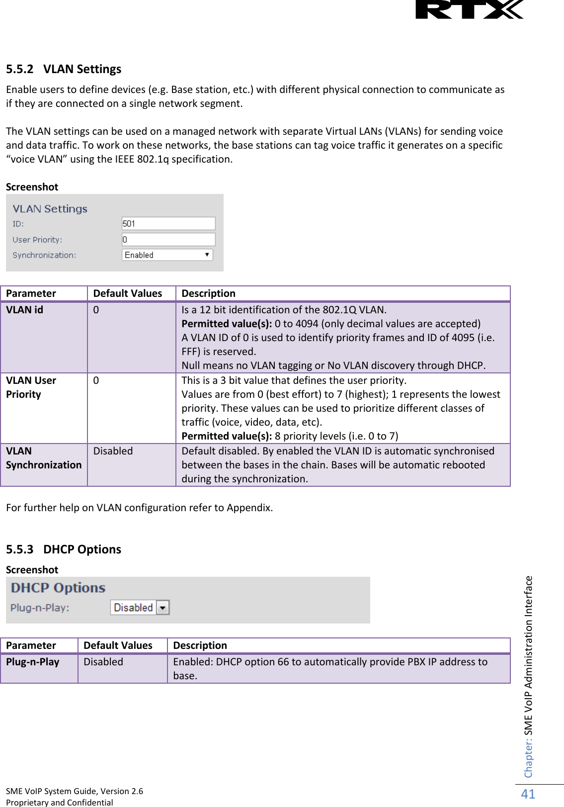
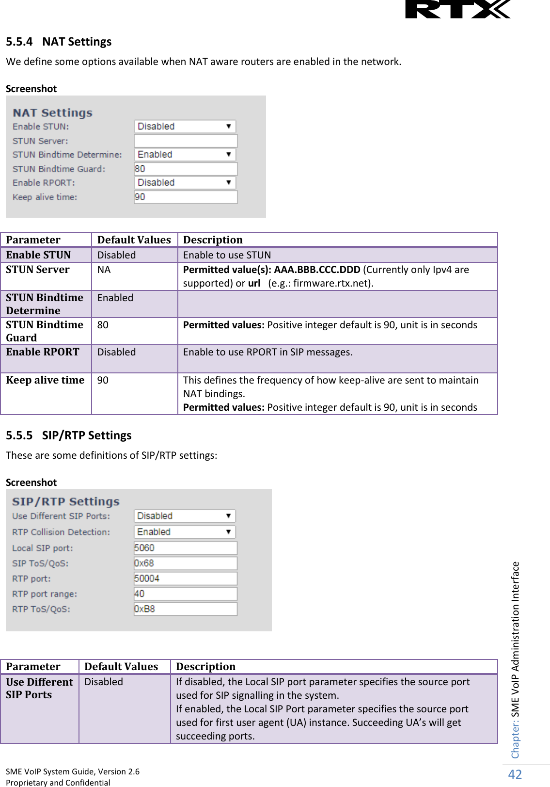
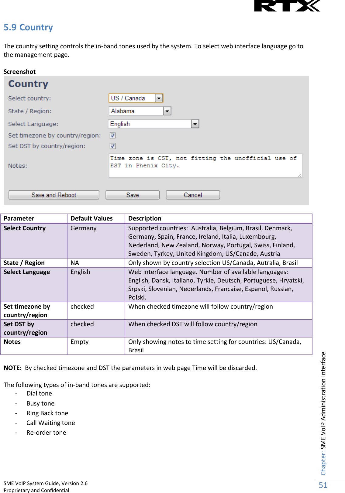
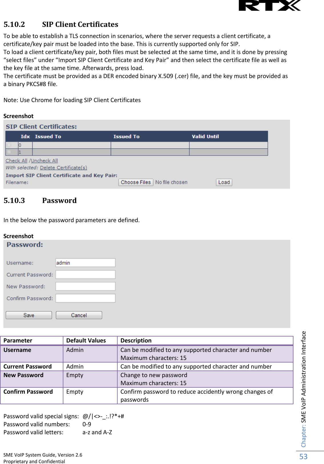
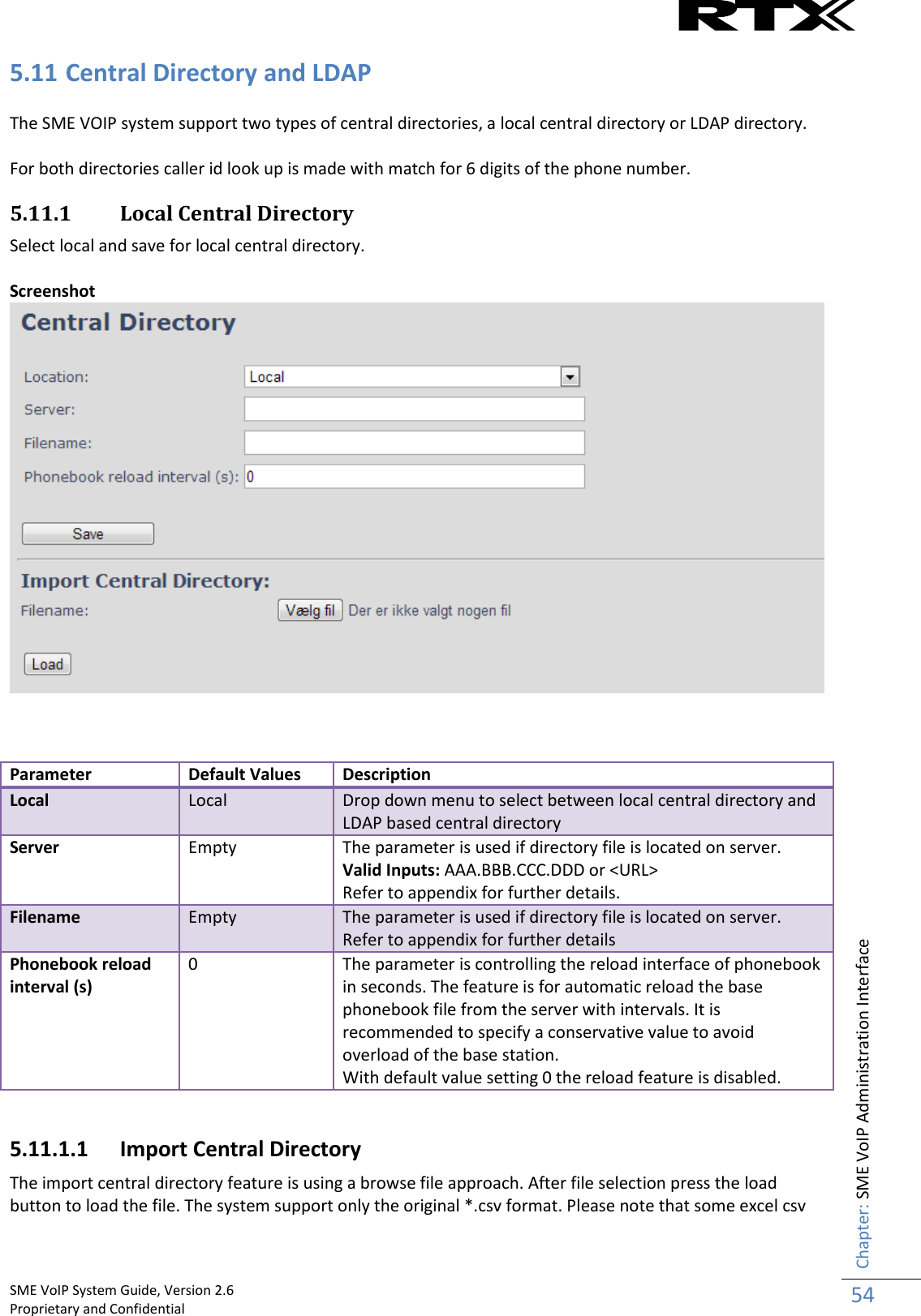
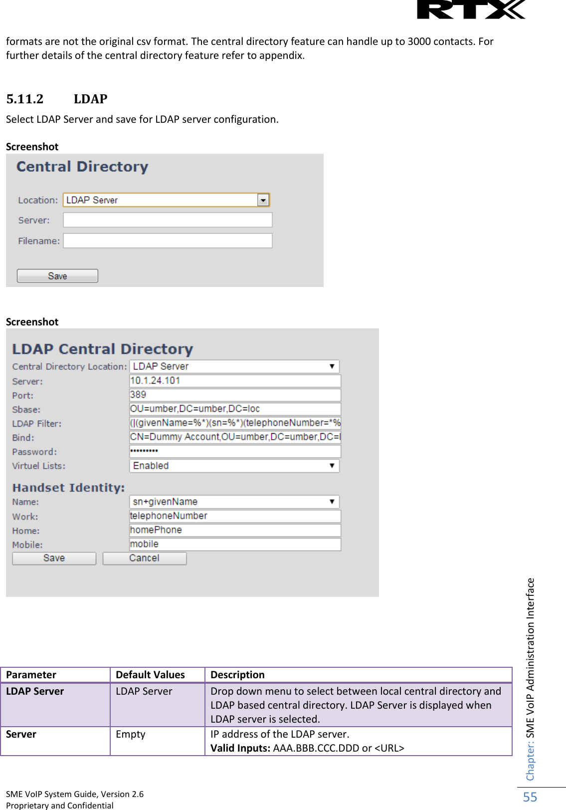
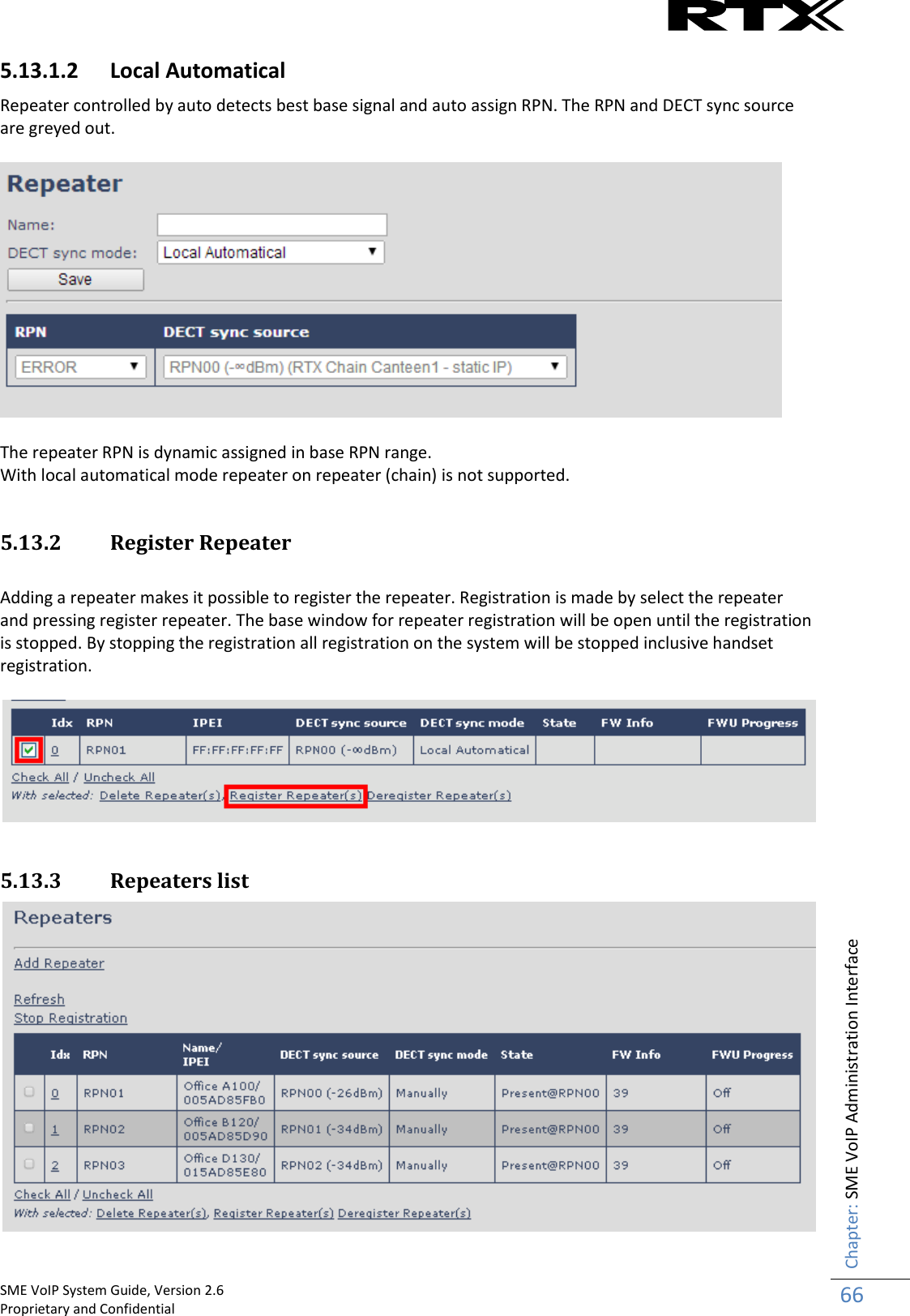
![SME VoIP System Guide, Version 2.6 Proprietary and Confidential Chapter: About This Document 7 1 About This Document This document describes the configuration, customization, management, operation, maintenance and trouble shooting of the SME VoIP System (RTX8663 base, RTX8630 handset, RTX8430 handset, RTX8830 ruggedized handset and RTX4024 Repeater) in RTX generic mode. For customer specific modes refer to specific customer agreements, which describe the software operational deviations from this document. For handset detailed user guide refer to [1]. 1.1 Audience Who should read this guide? First, this guide is intended for networking professionals responsible for designing and implementing RTX based enterprise networks. Second, network administrators and IT support personnel that need to install, configure, maintain and monitor elements in a “live” SME VoIP network will find this document helpful. Furthermore, anyone who wishes to gain knowledge on fundamental features in the Beatus system can also benefit from this material. 1.2 When Should I Read This Guide Read this guide before you install the core network devices of VoIP SME System and when you are ready to setup or configure SIP server, NAT aware router, advanced VLAN settings, base stations, and multi cell setup. This manual will enable you to set up components in your network to communicate with each other and also deploy a fully functionally VoIP SME System. 1.3 Important Assumptions This document was written with the following assumptions in mind: 1) You have understanding of network deployment in general 2) You have working knowledge of basic TCP/IP/SIP protocols, Network Address Translation, etc... 3) A proper site survey has been performed, and the administrator have access to these plans 1.4 What’s Inside This Guide We summarize the contents of this document in the table below: Where Is It? Content Purpose Chapter 2 Introduction to the SME VoIP Network To gain knowledge about the different elements in a typical SME VoIP Network Chapter 3 Installation of Base station/Repeater Considerations to remember before unwrapping and installing base units and repeaters Chapter 4 Making Handsets Ready To determine precautions to take in preparing handsets for use in the system Chapter 5 SME VoIP Administration Interface To learn about the Configuration Interface and define full meaning of various parameters needed to be setup in the system. Chapter 6 Multi-Cell Setup & Management Learn how to add servers and setup multiple bases into a multi-cell network Chapter 7 Registration Management - Learn how to register handset and extensions to base](https://usermanual.wiki/RTX/X8663/User-Guide-3114207-Page-7.png)
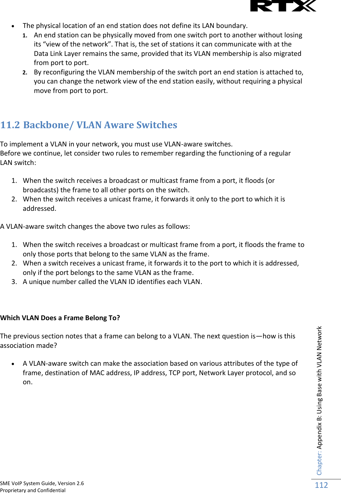
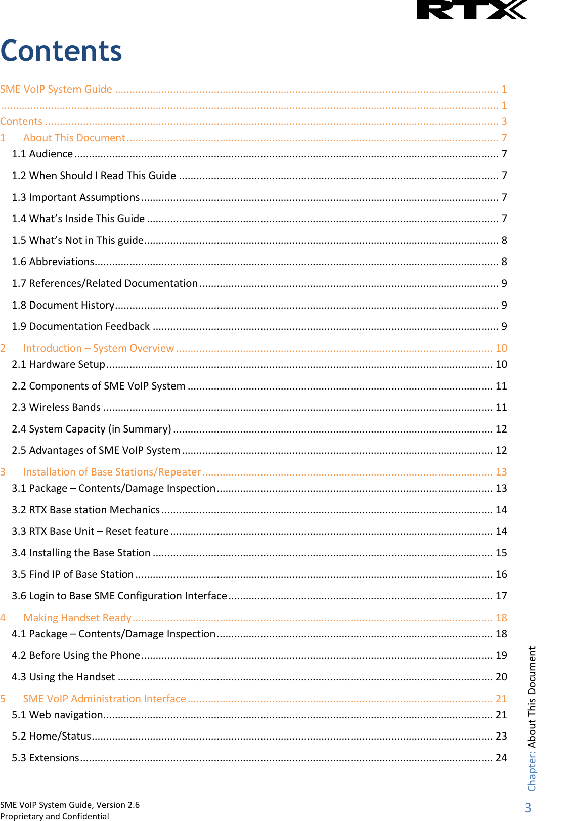
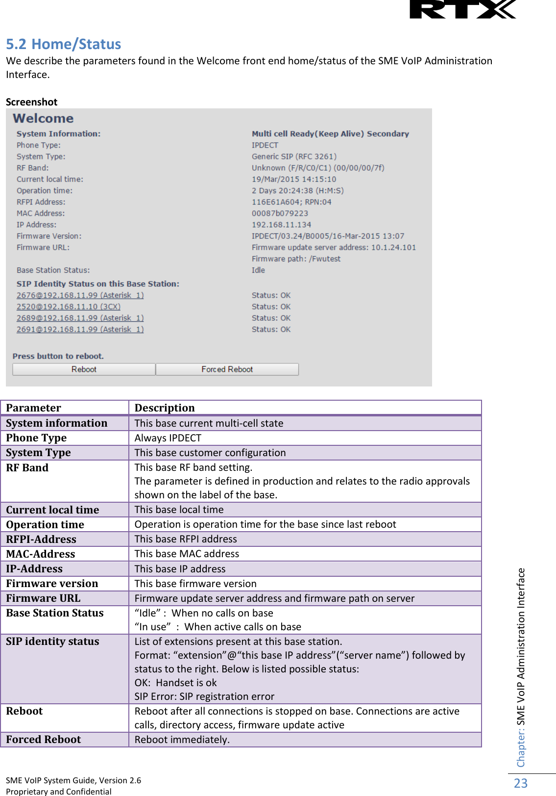
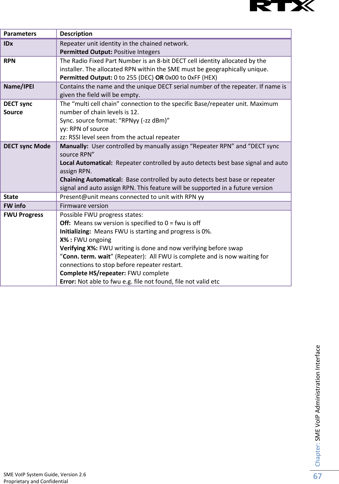
![SME VoIP System Guide, Version 2.6 Proprietary and Confidential Chapter: About This Document 9 1.7 References/Related Documentation [1]: RTX8430 Handset_Manual_Operations_v1.1 RTX8630 Handset_Manual_Operations_v1.2 RTX8830_Handset_Manual_Operations V1.3 [2]: How to Deploy SME VOIP System v1.4 [3]: Provisioning of SME VoIP System (10) 1.8 Document History Revision Author Issue Date Comments 2.2 KMR 24-July-2014 Document updated to include the new RTX8830 handset and features 2.1 KMR 2-April-2014 Document updated to match V316 software feature level in generic mode Server page: Added TLS, SRTP, server alias Updated other parts affected by server alias Repeater page: Added repeater alias References versions updated 2.0 KMR 1-Oct-2013 Document updated to match V306 software feature level in generic mode Home status: Base status added Extension page: Sort function added, Registration control added. Added unique extension note. Network: VLAN sync added Management: language moved to country Time: Added save button Country: Added language selection Security: Password double confirm added Central dir/LDAP: Reload option added Multicell: In status added Sync data IP Repeaters: Added stop registration Statistics: Added repeater statistics Section 6.3 multicell – modified sequence 1.9 KMR 17-July-2013 Document updated to match V303 software feature level (security, multiline, time settings). Primary Data Sync IP: Added note about data sync source. 1.8 KMR 18-Feb-2013 Restructured and updated to software V273 operation 2.3 KMR 8-Sep-2014 Updated to V322 operation with RTX8830 handset 2.4 KMR 5-Jan-2015 Aligned with V323B14 operation 2.5 KMR 16-Feb-2015 Aligned with V324 operation 2.6 KMR 12-Jan-2016 Added V355 system size capabilities 1.9 Documentation Feedback We always strive to produce the best and we also value your comments and suggestions about our documentation. If you have any comments about this guide, please enter them through the Feedback link on the RTX website. We will use your feedback to improve the documentation.](https://usermanual.wiki/RTX/X8663/User-Guide-3114207-Page-9.png)


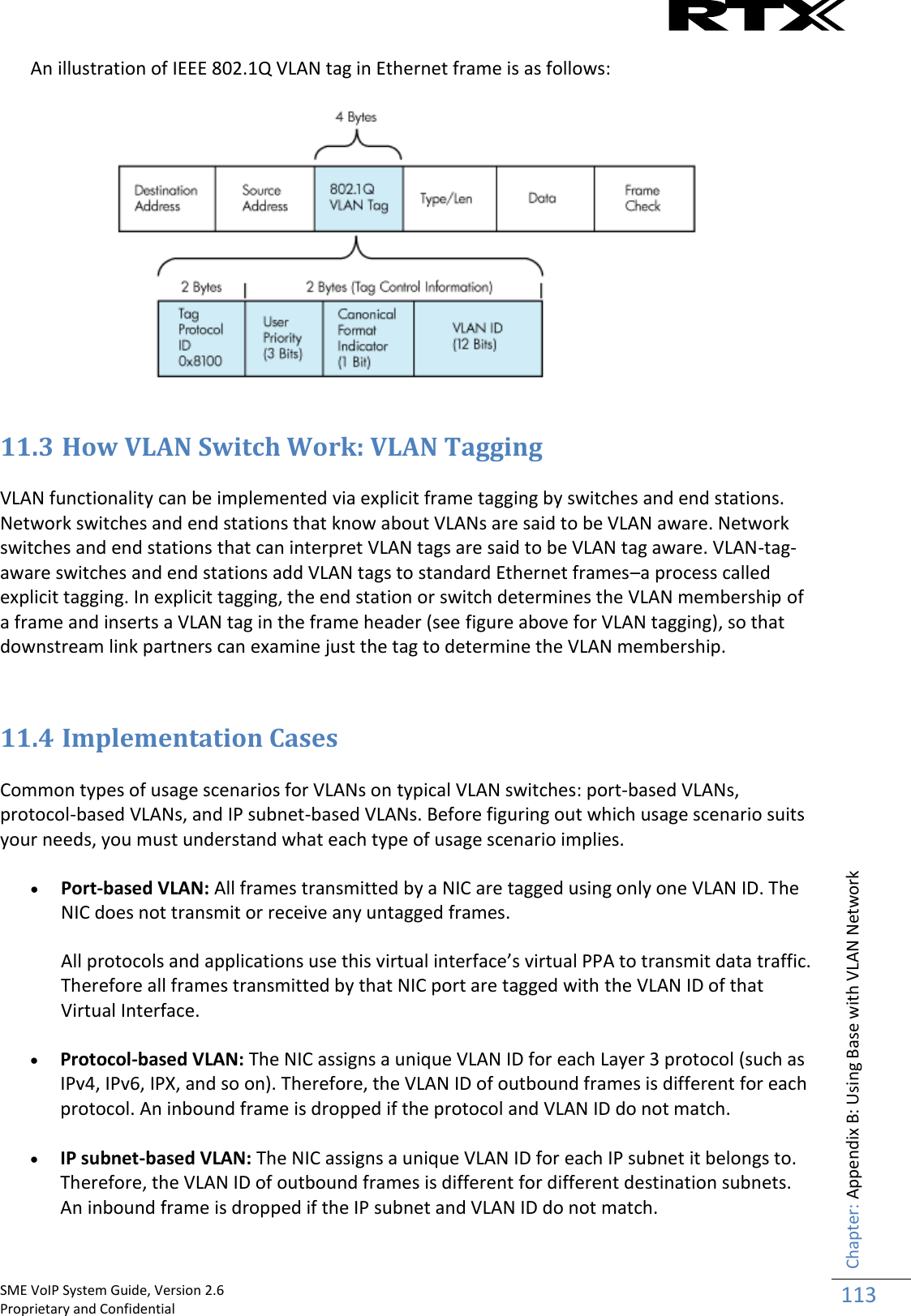
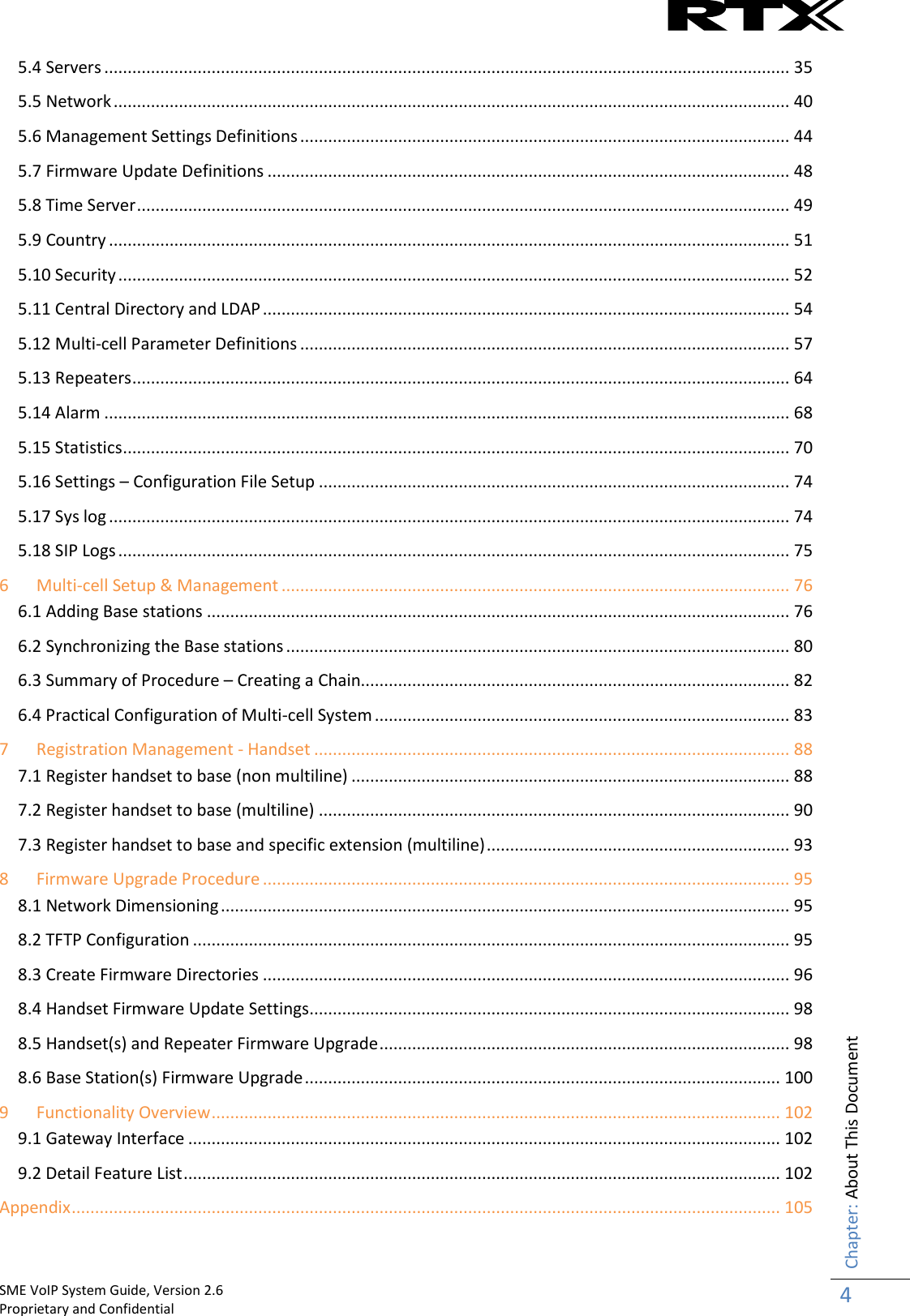
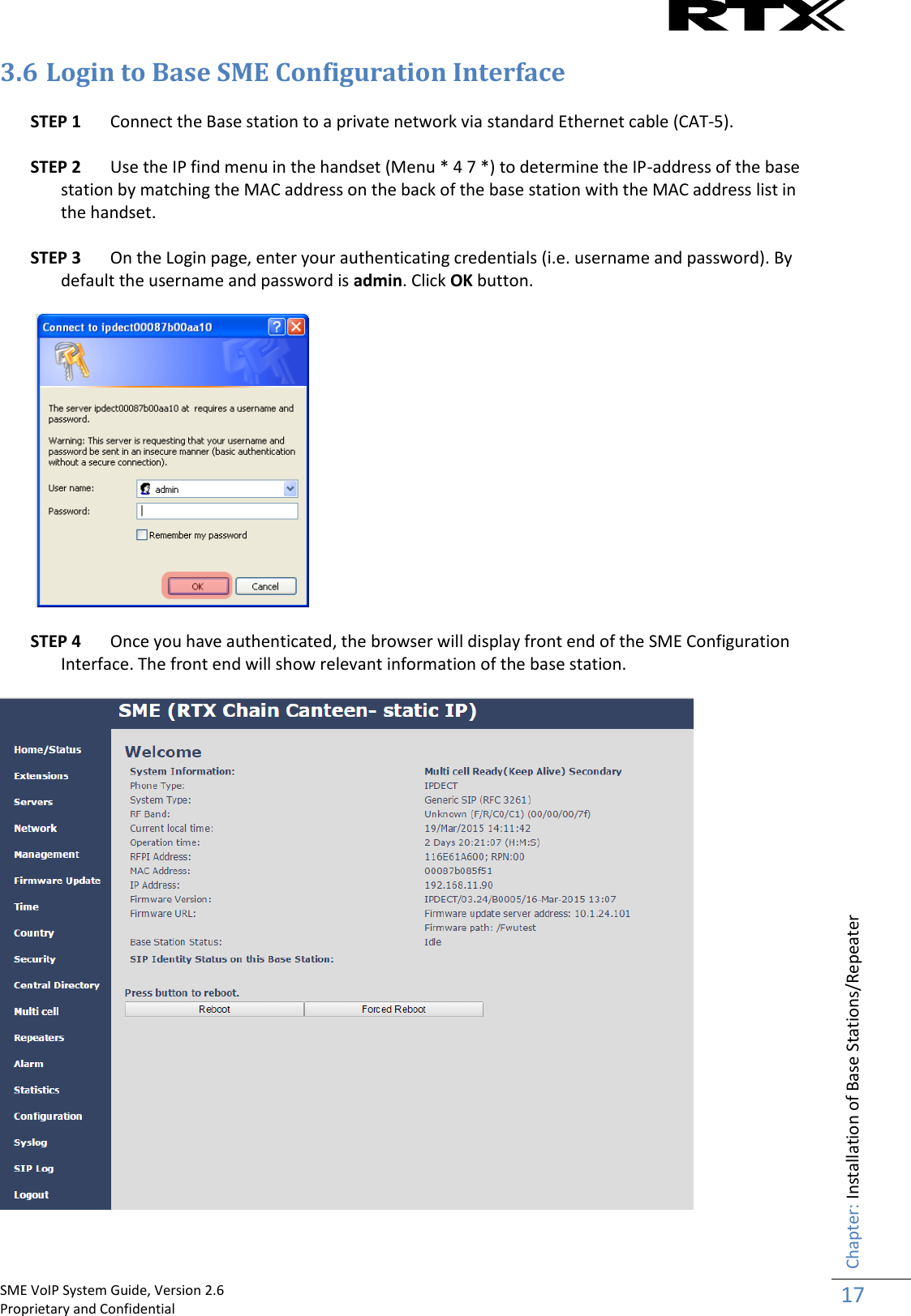
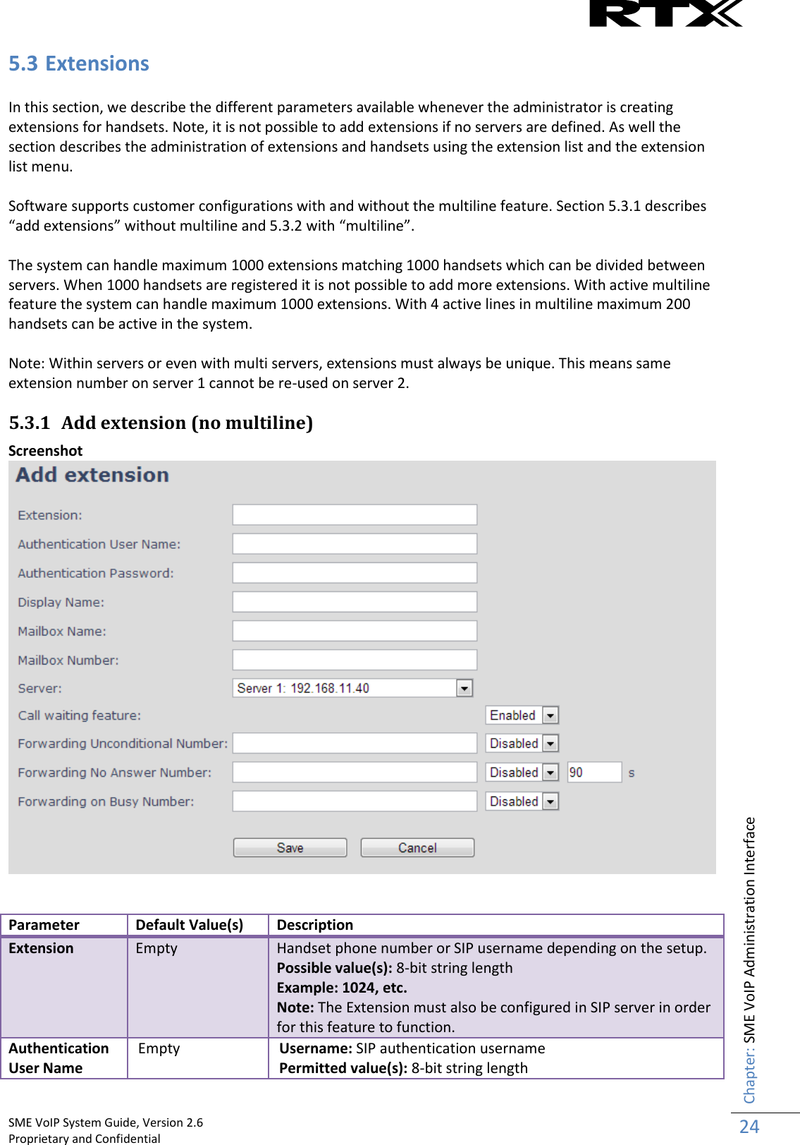
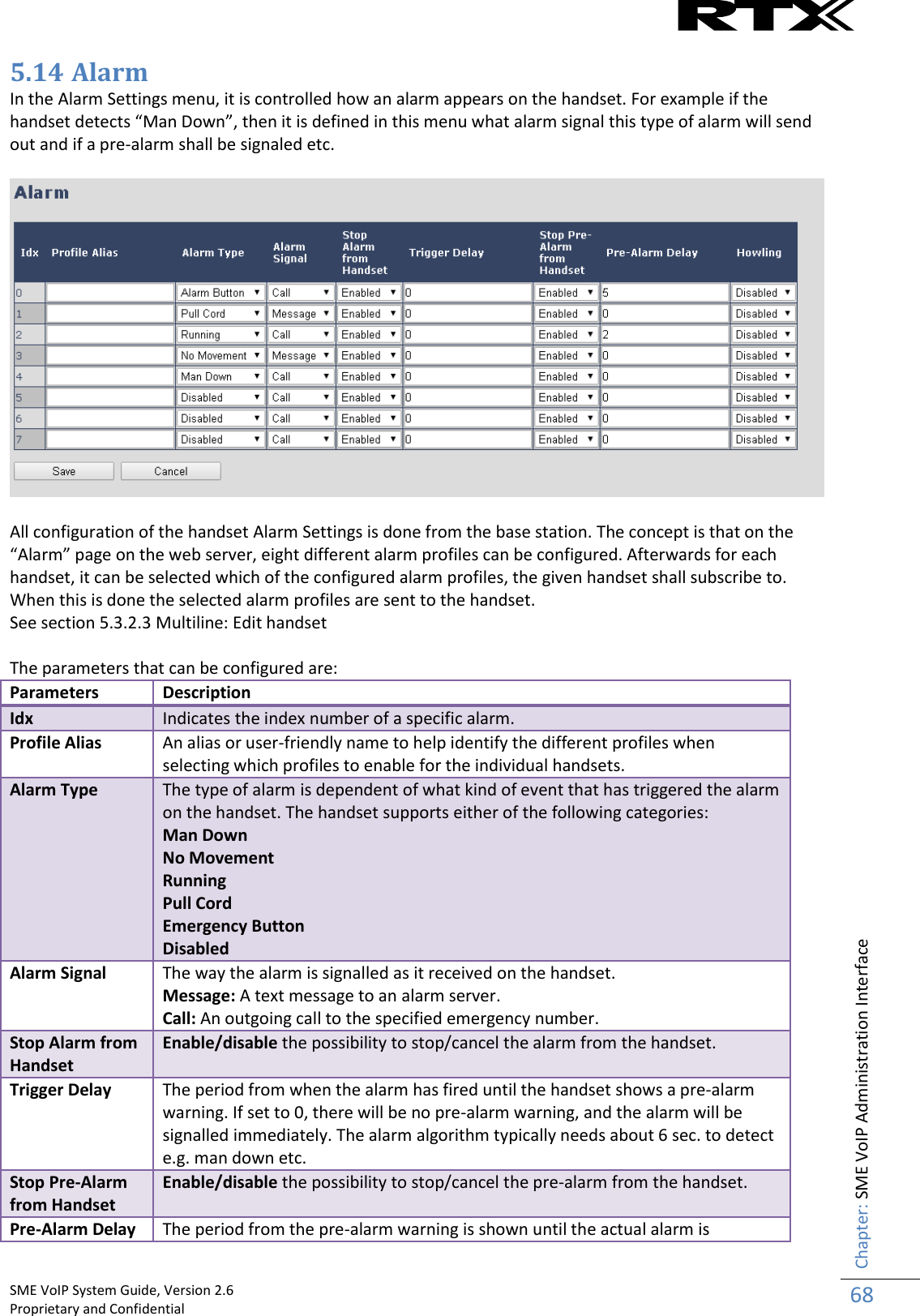
![SME VoIP System Guide, Version 2.6 Proprietary and Confidential Chapter: Installation of Base Stations/Repeater 16 3.5 Find IP of Base Station To find IP of the installed base station two methods can be used; Using handset Find IP feature or browser IPDECT feature. 3.5.1 Using handset Find IP feature On the handset press “Menu” key followed by the keys: *47* to get the handset into find bases menu. The handset will now scan for 8663 bases. Depending on the amount of powered on bases with active radios and the distance to the base it can take up to minutes to find a base. - Use the cursor down/up to select the base MAC address for the base - The base IP address will be shown in the display The feature is also used for deployment. For further details refer to reference [2]. 3.5.2 Using browser IPDECT Open any standard browser and enter the address: http://ipdect<MAC-Address-Base-Station> for e.g. http://ipdect00087B00AA10. This will retrieve the HTTP Web Server page from the base station with hardware address 00087B00AA10. This feature requires an available DNS server.](https://usermanual.wiki/RTX/X8663/User-Guide-3114207-Page-16.png)
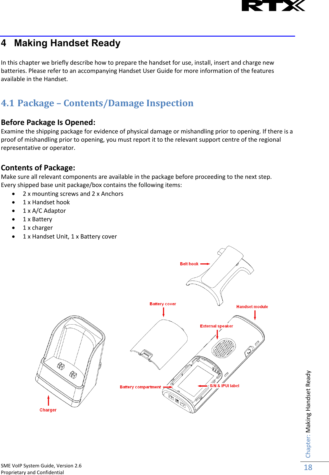

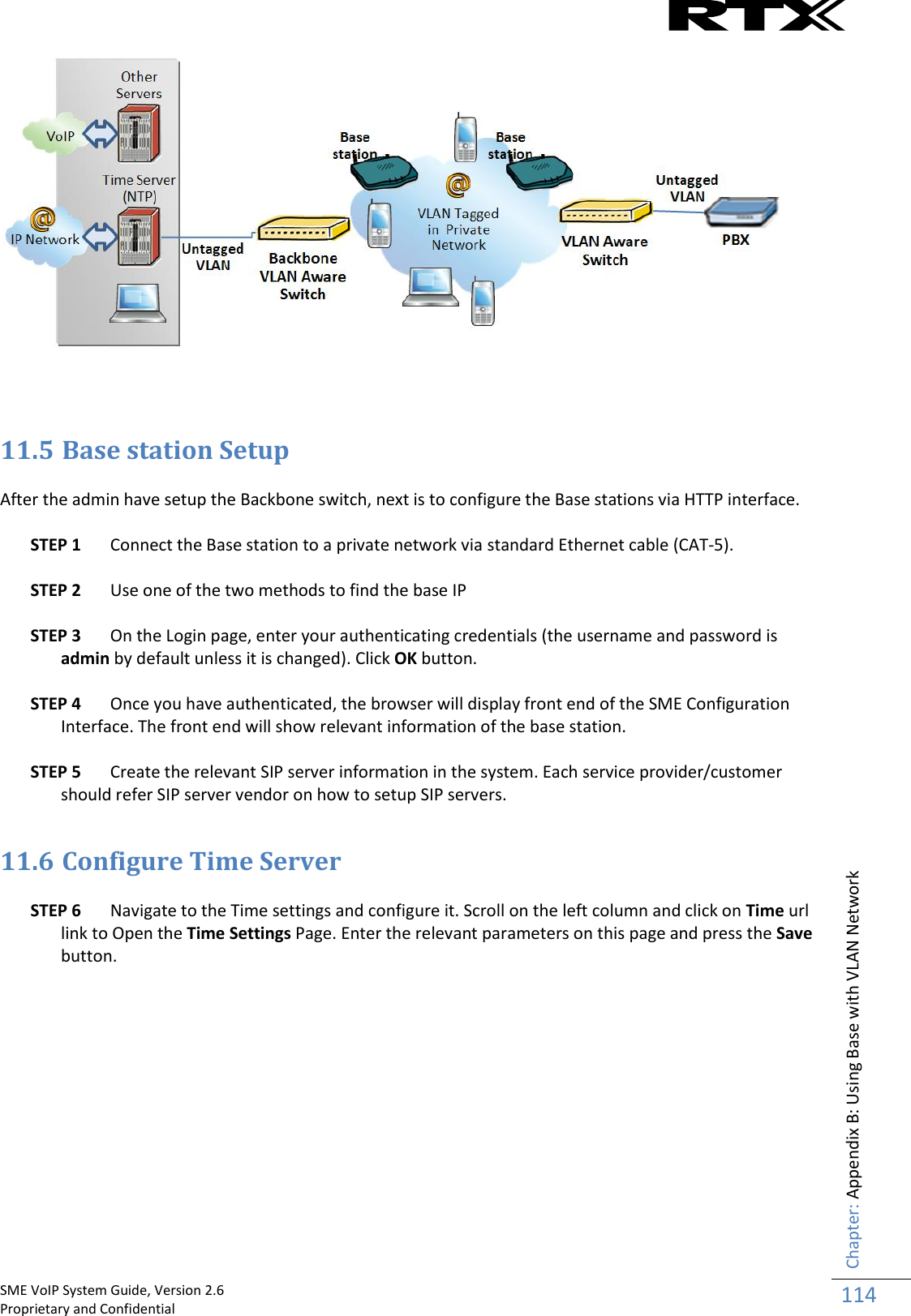
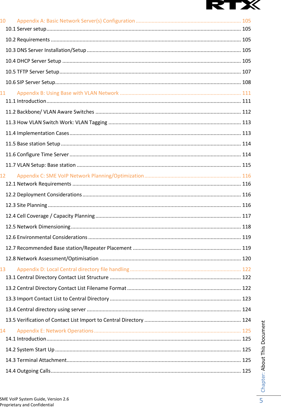
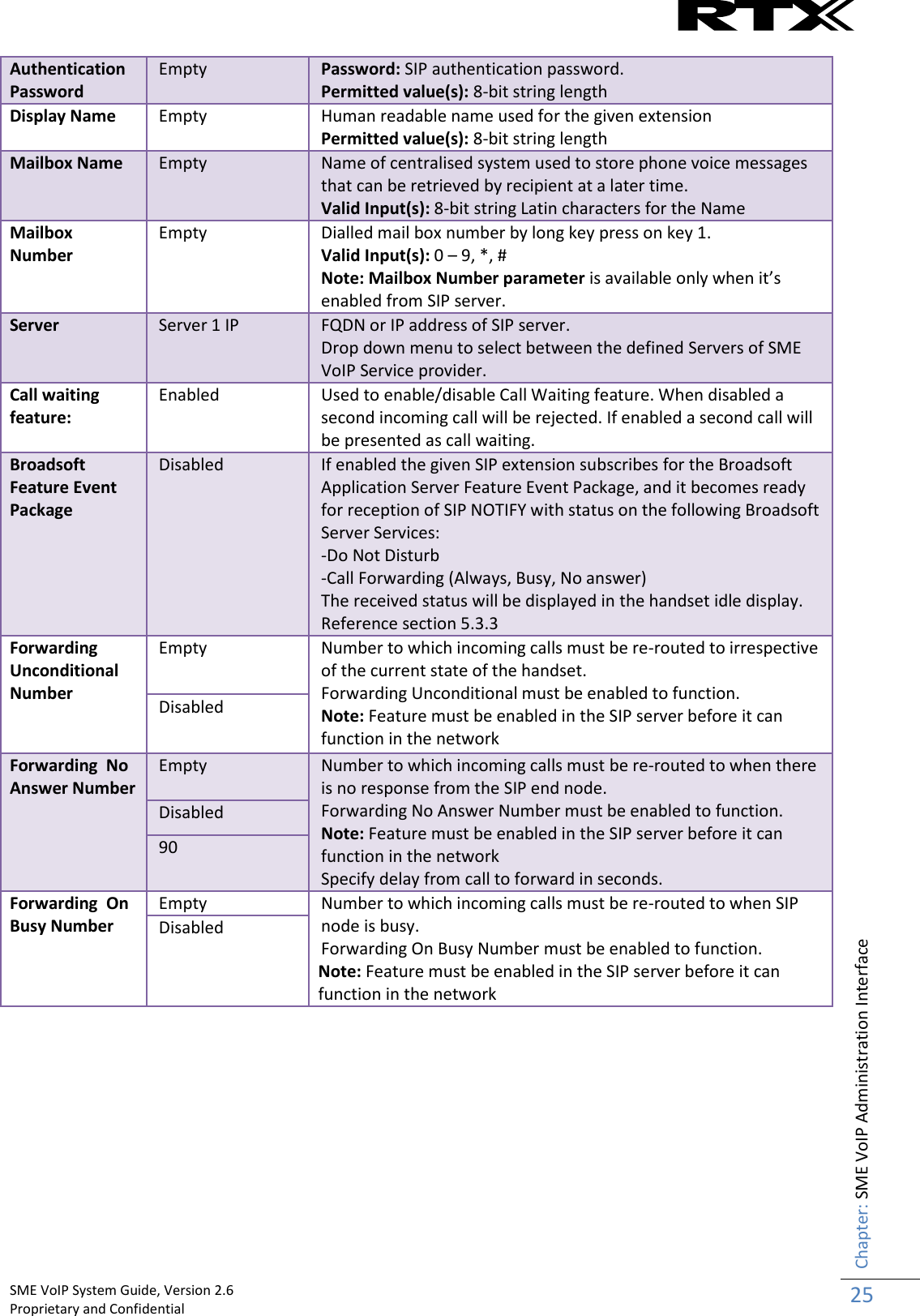
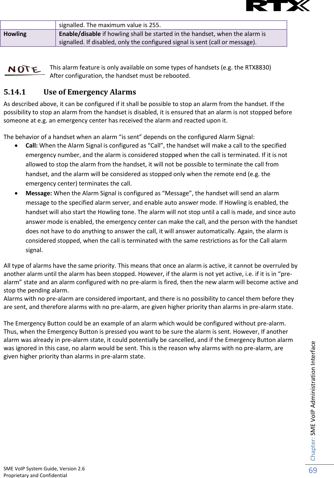
![SME VoIP System Guide, Version 2.6 Proprietary and Confidential Chapter: Making Handset Ready 20 Handset Serial Number The serial number (IPEI/IPUI number) of each handset is found either on a label, which is placed behind the battery, or on the packaging label. First, lift off handset back cover and lift the battery and read the serial number. The serial number is needed to enable service to the handset. It must be programmed into the system database via the SME VoIP Configuration interface. Replace Battery Remove Back Cover from Handset. Remove the old battery and replace with a new one. 4.3 Using the Handset Please refer handset manual for detailed description of how to use the handset features [1].](https://usermanual.wiki/RTX/X8663/User-Guide-3114207-Page-20.png)


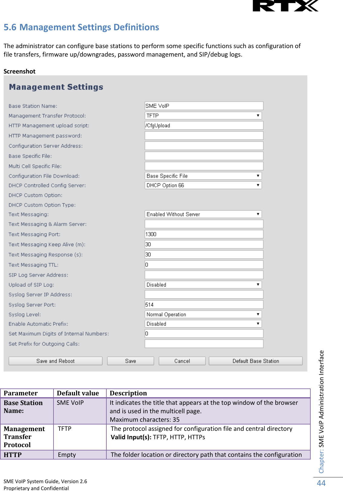
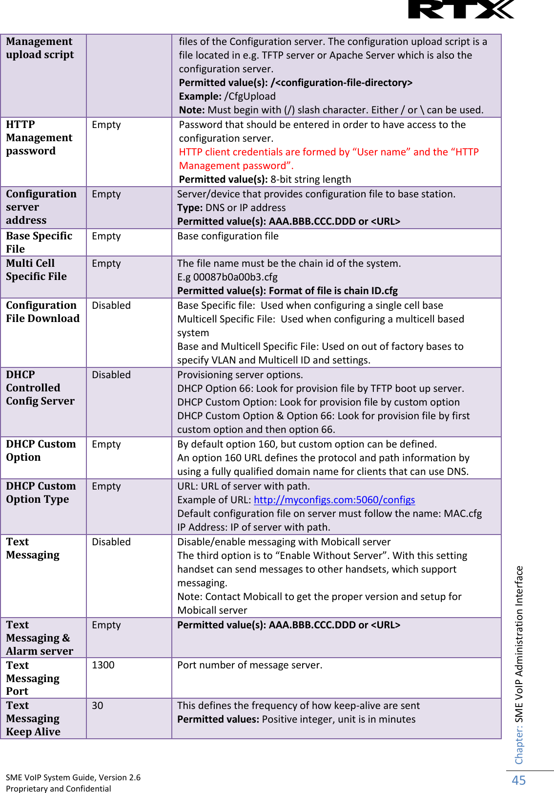
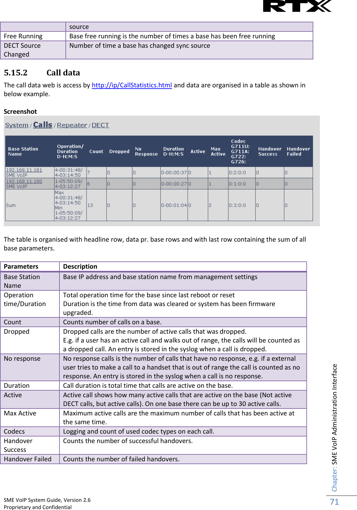
![SME VoIP System Guide, Version 2.6 Proprietary and Confidential Chapter: SME VoIP Administration Interface 46 (m) Text Messaging Response (s) 30 This defines the frequency of how response timeout Permitted values: Positive integer, unit is in seconds Text Messaging TTL 0 This defines the text messaging time to live Permitted values: Positive integer, unit is in seconds SIP Log Server Address Empty Permitted value(s): AAA.BBB.CCC.DDD or <URL> Requires a predefined folder named: \SIP Upload of SIP Log Disabled Enable this option to save low level SIP debug messages to the server. The SIP logs are saved in the file format: <MAC_Address><Time_Stamp>SIP.log Syslog Server IP-Address Empty Permitted value(s): AAA.BBB.CCC.DDD or <URL> Syslog Server Port Empty Port number of syslog server. Syslog Level Off Off: No data is saved on syslog server Normal Operation: Normal operation events are logged, incoming call, outgoing calls, handset registration, DECT location, and call lost due to busy, critical system errors, general system information. System Analyze: Handset roaming, handset firmware updates status. The system 46nalyse level also contains the messages from normal operation. Debug: Used by RTX for debug. Should not be enabled during normal operation. Enable Automatic Prefix Disabled Disabled: Feature off. Enabled: The base will add the leading digit defined in “Set Prefix for Outgoing Calls”. Enabled + fall through on * and #: Will enable detection of * or # at the first digit of a dialled number. In case of detection the base will not complete the dialled number with a leading 0. Examples: 1: dialed number on handset * 1234 - > dialed number to the pabx *1234 2: dialed number on handset #1234 - > dialed number to the pabx #1234 3: dialed number on handset 1234 - > dialed number to the pabx 01234 Set Maximum Digits of Internal Numbers 0 Used to detect internal numbers. In case of internal numbers no prefix number will be added to the dialled number. Set Prefix for Outgoing Calls Empty Prefix number for the enabled automatic prefix feature. Permitted value(s): 1 to 9999 There are three ways of configuring the system. 1. Manual configuration by use of the Web server in the base station(s) 2. By use of configuration files that are uploaded from a disk via the “Configuration” page on the Web server. 3. By use of configuration files which the base station(s) download(s) from a configuration server. For further details refer to doc reference [3].](https://usermanual.wiki/RTX/X8663/User-Guide-3114207-Page-46.png)

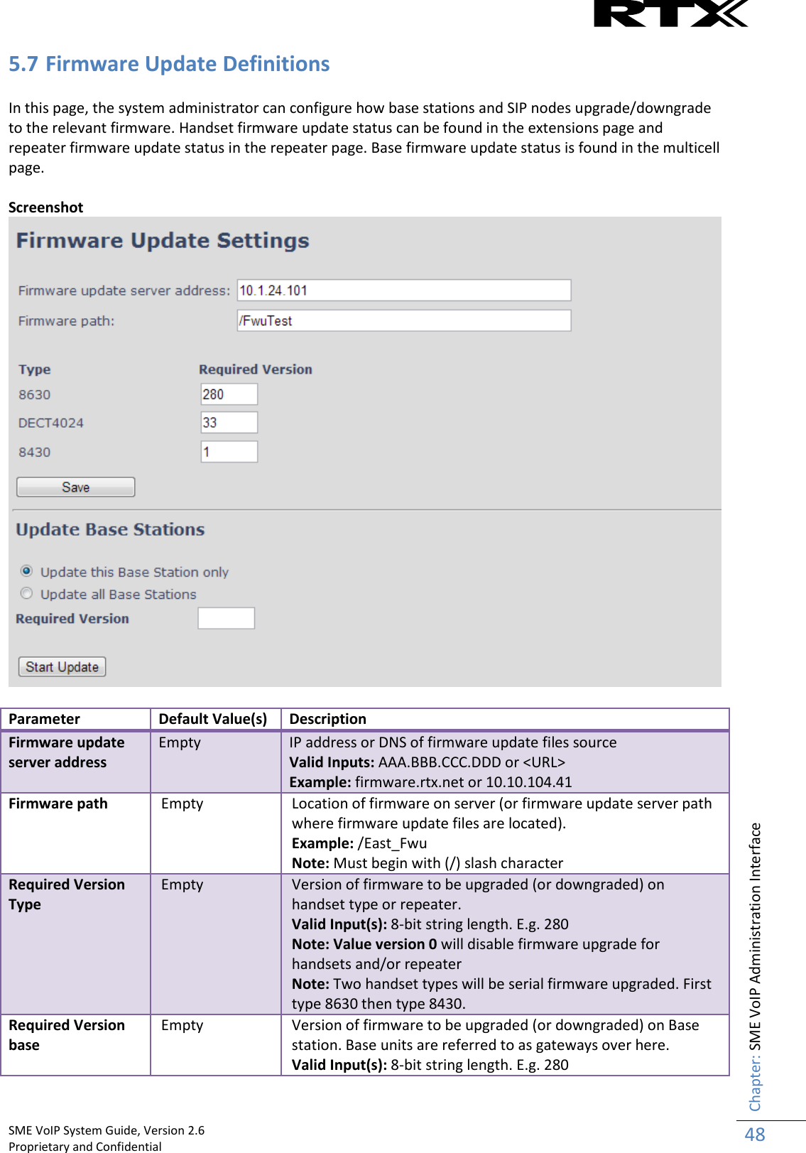


![SME VoIP System Guide, Version 2.6 Proprietary and Confidential Chapter: SME VoIP Administration Interface 74 5.16 Settings – Configuration File Setup This page provides non editable information showing the native format of entire SME VoIP Configuration parameter settings. The settings format is exactly what is used in the configuration file. The configuration file is found in the TFTP server. The filename for the configuration server is <MAC_Address>.cfg. The configuration file is saved in the folder /Config in the TFTP sever. There are three ways to edit the configuration file or make changes to the settings page: 1) Using the SME VoIP Configuration interface to make changes. Each page of the HTTP web interface is a template for which the user can customise settings in the configuration file. 2) Retrieving the relevant configuration file from the TFTP and modify and enter new changes. This should be done with an expert network administrator. 3) Navigate to the settings page of the VoIP SME Configuration interface > copy the contents of settings > save them to any standard text editor e.g. notepad > modify the relevant contents, make sure you keep the formatting intact > Save the file as <Enter_MAC_Address_of_RFP>.cfg > upload it into the relevant TFTP server. For details refer to [3]. An example of contents of settings is as follows: ~RELEASE=UMBER_FP_V0054 %GMT_TIME_ZONE%:16 %COUNTRY_VARIANT_ID%:18 %FWU_POLLING_ENABLE%:0 %FWU_POLLING_MODE%:0 %FWU_POLLING_PERIOD%:86400 %FWU_POLLING_TIME_HH%:3 %FWU_POLLING_TIME_MM%:0 %DST_ENABLE%:2 %DST_FIXED_DAY_ENABLE%:0 %DST_START_MONTH%:3 %DST_START_DATE%:1 .... .... 5.17 Sys log This page shows live feed of system level messages of the current base station. The messages the administrator see here depends on what is configured at the Management settings. The Debug logs can show only Boot Log or Everything that is all system logs including boot logs. The Debug log is saved in the file format <Time_Stamp>b.log in a relevant location in the TFTP server as specified in the upload script. A sample of debug logs is as follows: 0101000013 [N](01):DHCP Enabled 0101000013 [N](01):IP Address: 192.168.10.101 0101000013 [N](01):Gateway Address: 192.168.10.254 0101000013 [N](01):Subnet Mask: 255.255.255.0 0101000013 [N](01):TFTP boot server not set by DHCP. Using Static. 0101000013 [N](01):DHCP Discover completed 0101000013 [N](01):Time Server: 192.168.10.11 0101000013 [N](01):Boot server: 10.10.104.63 path: Config/ Type: TFTP 0101000013 [N](01):RemCfg: Download request of Config/00087b077cd9.cfg from 10.10.104.63 using TFTP](https://usermanual.wiki/RTX/X8663/User-Guide-3114207-Page-74.png)
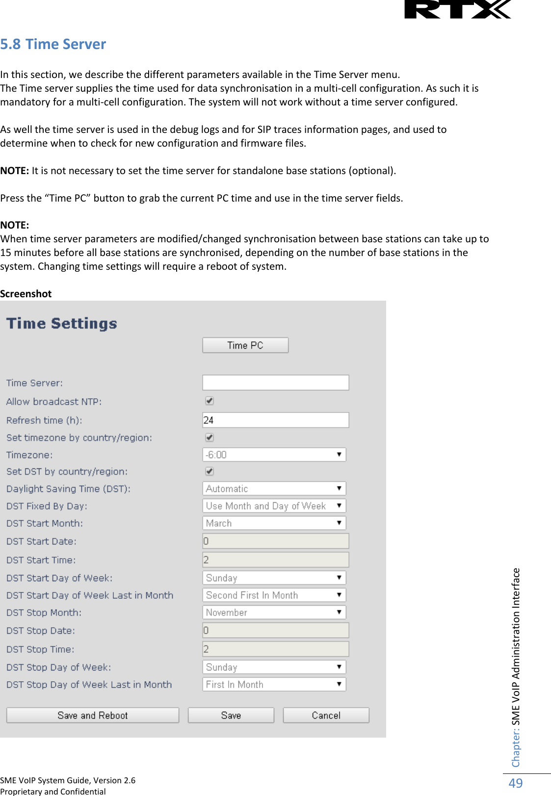
:accept called from task 7 0101000014 [N](01):TrelAccept success [4]. Listening on port 10010 0101000019 [N](01):RemCfg: Download request of Config/00087b077cd9.cfg from 10.10.104.63 using TFTP 0101000019 [W](01):Load of Config/00087b077cd9.cfg from 10.10.104.63 failed To dump the log simply copy and page the full contents. 5.18 SIP Logs This page shows SIP server related messages that are logged during the operation of the SME system. The full native format of SIP logs is saved in the TFTP server as <MAC_Address><Time_Stamp>SIP.log These logs are saved in 2 blocks of 17Kbytes. When a specific SIP log is fully dumped to one block, the next SIP logs are dumped to the other blocks. An example of SIP logs is shown below: ..... Sent to udp:192.168.10.10:5080 at 12/11/2010 11:56:42 (791 bytes) REGISTER sip:192.168.10.10:5080 SIP/2.0 Via: SIP/2.0/UDP 192.168.10.101:5063;branch=z9hG4bKrlga4nkuhimpnj4.qx Max-Forwards: 70 From: <sip:Ext003@192.168.10.10:5080>;tag=3o5l314 To: <sip:Ext003@192.168.10.10:5080> Call-ID: p9st.zzrfff66.ah8 CSeq: 6562 REGISTER Contact: <sip:Ext003@192.168.10.101:5063> Allow: INVITE, CANCEL, BYE, ACK, REGISTER, OPTIONS, REFER, SUBSCRIBE, NOTIFY, MESSAGE, INFO, PRACK Expires: 120 User-Agent: Generic-DPV-001-A-XX(Generic_SIPEXT2MLUA_v1) Content-Type: application/X-Generic_SIPEXT2MLv1 Content-Length: 251 ..... To dump the log simply copy and page the full contents.](https://usermanual.wiki/RTX/X8663/User-Guide-3114207-Page-75.png)


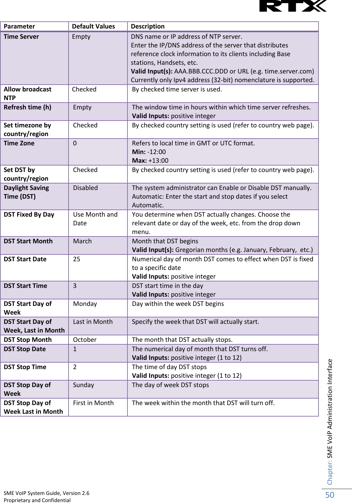
![SME VoIP System Guide, Version 2.6 Proprietary and Confidential Chapter: Firmware Upgrade Procedure 101 8.6.1 Base firmware confirmation Base station firmware version status in a multicell environment can be seen in the multicell base station group overview page, column 4. 8.6.2 Verification of Firmware Upgrade Syslog information when Management Syslog level is set to “Debug” [ FWU Downloading File tftp://10.1.24.101/FwuPath/Beatus/BeatusSw_4181_v0202.fwu] [ Base FWU started] [ Base FWU ended with exit code 2101 (NE_FILE_TRANSFER_EOF): End of file] The log window of the TFTP server:](https://usermanual.wiki/RTX/X8663/User-Guide-3114207-Page-101.png)