Users Manual

SME VoIP System Guide, Version 2.6
Proprietary and Confidential
Chapter: About This Document
1
SME VoIP System Guide
Installation & Configuration
Network Deployment
Operation & Management
Technical Reference Document
Version 2.6
© Jan-2016 RTX A/S, Denmark

SME VoIP System Guide, Version 2.6
Proprietary and Confidential
Chapter: About This Document
2
Trademarks
RTX and the combinations of its logo thereof are trademarks of RTX A/S, Denmark.
Other product names used in this publication are for identification purposes and maybe the trademarks of their respective
companies.
Disclaimer
The contents of this document are provided in connection with RTX products. RTX makes no representations with respect to
completeness or accuracy of the contents of this publication and reserves the right to make changes to product descriptions, usage,
etc., at any time without notice. No license, whether express, implied, to any intellectual property rights are granted by this
publication
Confidentiality
This document should be regarded as confidential, unauthorized copying is not allowed
© Jan-2016 RTX A/S, Denmark, All rights reserved
http://www.rtx.dk

SME VoIP System Guide, Version 2.6
Proprietary and Confidential
Chapter: About This Document
3
Contents
SME VoIP System Guide .................................................................................................................................... 1
........................................................................................................................................................................... 1
Contents ............................................................................................................................................................ 3
1 About This Document ................................................................................................................................ 7
1.1 Audience .................................................................................................................................................. 7
1.2 When Should I Read This Guide .............................................................................................................. 7
1.3 Important Assumptions ........................................................................................................................... 7
1.4 What’s Inside This Guide ......................................................................................................................... 7
1.5 What’s Not in This guide.......................................................................................................................... 8
1.6 Abbreviations ........................................................................................................................................... 8
1.7 References/Related Documentation ....................................................................................................... 9
1.8 Document History .................................................................................................................................... 9
1.9 Documentation Feedback ....................................................................................................................... 9
2 Introduction – System Overview ............................................................................................................. 10
2.1 Hardware Setup ..................................................................................................................................... 10
2.2 Components of SME VoIP System ......................................................................................................... 11
2.3 Wireless Bands ...................................................................................................................................... 11
2.4 System Capacity (in Summary) .............................................................................................................. 12
2.5 Advantages of SME VoIP System ........................................................................................................... 12
3 Installation of Base Stations/Repeater .................................................................................................... 13
3.1 Package – Contents/Damage Inspection ............................................................................................... 13
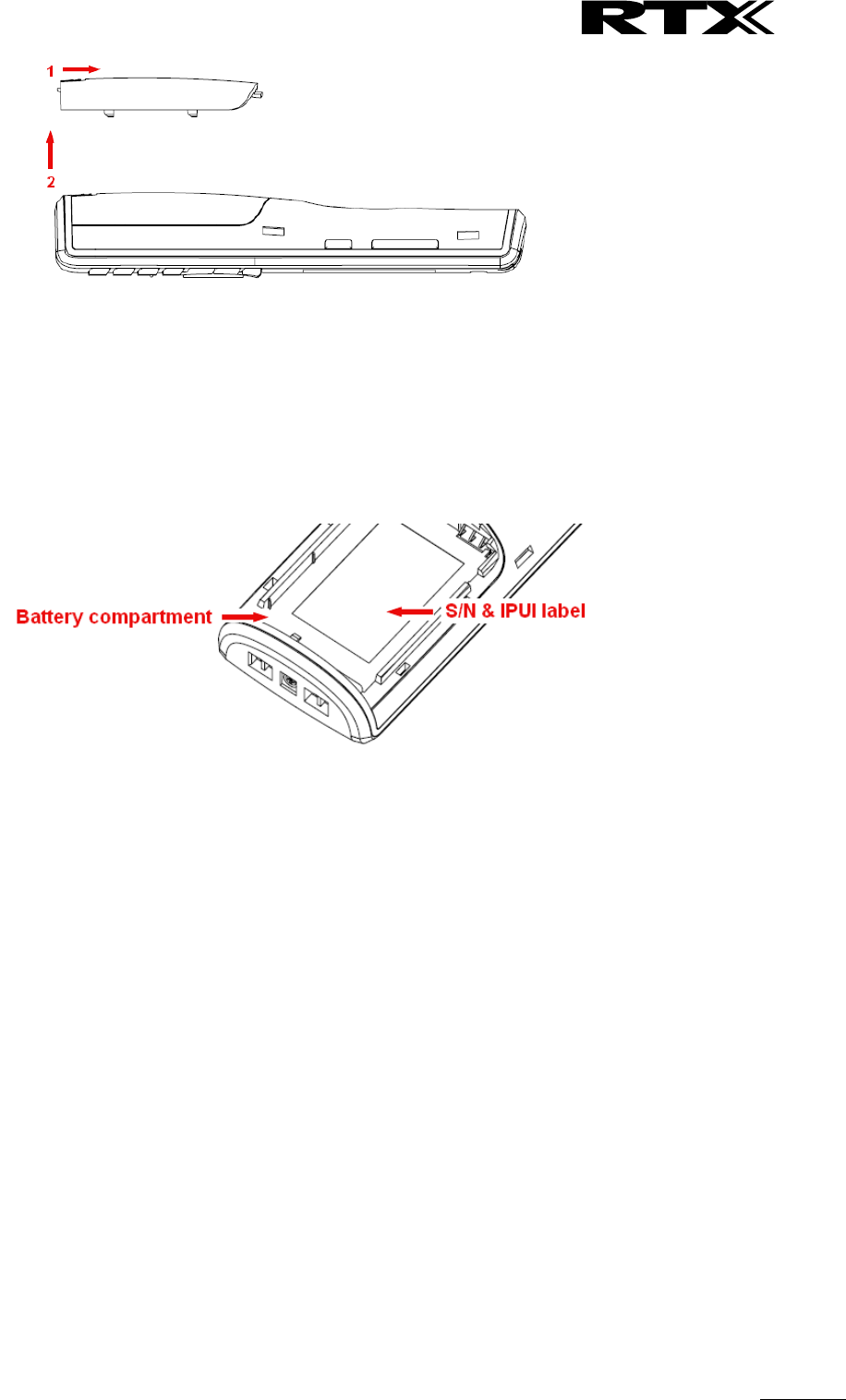
3.2 RTX Base station Mechanics .................................................................................................................. 14
3.3 RTX Base Unit – Reset feature ............................................................................................................... 14
3.4 Installing the Base Station ..................................................................................................................... 15
3.5 Find IP of Base Station ........................................................................................................................... 16
3.6 Login to Base SME Configuration Interface ........................................................................................... 17
4 Making Handset Ready ............................................................................................................................ 18
4.1 Package – Contents/Damage Inspection ............................................................................................... 18
4.2 Before Using the Phone ......................................................................................................................... 19
4.3 Using the Handset ................................................................................................................................. 20
5 SME VoIP Administration Interface ......................................................................................................... 21
5.1 Web navigation ...................................................................................................................................... 21
5.2 Home/Status .......................................................................................................................................... 23
5.3 Extensions .............................................................................................................................................. 24

SME VoIP System Guide, Version 2.6
Proprietary and Confidential
Chapter: About This Document
4
5.4 Servers ................................................................................................................................................... 35
5.5 Network ................................................................................................................................................. 40
5.6 Management Settings Definitions ......................................................................................................... 44
5.7 Firmware Update Definitions ................................................................................................................ 48
5.8 Time Server ............................................................................................................................................ 49
5.9 Country .................................................................................................................................................. 51
5.10 Security ................................................................................................................................................ 52
5.11 Central Directory and LDAP ................................................................................................................. 54
5.12 Multi-cell Parameter Definitions ......................................................................................................... 57
5.13 Repeaters ............................................................................................................................................. 64
5.14 Alarm ................................................................................................................................................... 68
5.15 Statistics ............................................................................................................................................... 70
5.16 Settings – Configuration File Setup ..................................................................................................... 74
5.17 Sys log .................................................................................................................................................. 74
5.18 SIP Logs ................................................................................................................................................ 75
6 Multi-cell Setup & Management ............................................................................................................. 76
6.1 Adding Base stations ............................................................................................................................. 76
6.2 Synchronizing the Base stations ............................................................................................................ 80
6.3 Summary of Procedure – Creating a Chain............................................................................................ 82
6.4 Practical Configuration of Multi-cell System ......................................................................................... 83
7 Registration Management - Handset ...................................................................................................... 88
7.1 Register handset to base (non multiline) .............................................................................................. 88
7.2 Register handset to base (multiline) ..................................................................................................... 90
7.3 Register handset to base and specific extension (multiline) ................................................................. 93
8 Firmware Upgrade Procedure ................................................................................................................. 95
8.1 Network Dimensioning .......................................................................................................................... 95
8.2 TFTP Configuration ................................................................................................................................ 95
8.3 Create Firmware Directories ................................................................................................................. 96
8.4 Handset Firmware Update Settings ....................................................................................................... 98
8.5 Handset(s) and Repeater Firmware Upgrade ........................................................................................ 98
8.6 Base Station(s) Firmware Upgrade ...................................................................................................... 100
9 Functionality Overview .......................................................................................................................... 102
9.1 Gateway Interface ............................................................................................................................... 102
9.2 Detail Feature List ................................................................................................................................ 102
Appendix ........................................................................................................................................................ 105

SME VoIP System Guide, Version 2.6
Proprietary and Confidential
Chapter: About This Document
5
10 Appendix A: Basic Network Server(s) Configuration ......................................................................... 105
10.1 Server setup ....................................................................................................................................... 105
10.2 Requirements .................................................................................................................................... 105
10.3 DNS Server Installation/Setup ........................................................................................................... 105
10.4 DHCP Server Setup ............................................................................................................................ 105
10.5 TFTP Server Setup .............................................................................................................................. 107
10.6 SIP Server Setup ................................................................................................................................. 108
11 Appendix B: Using Base with VLAN Network .................................................................................... 111
11.1 Introduction ....................................................................................................................................... 111
11.2 Backbone/ VLAN Aware Switches ..................................................................................................... 112
11.3 How VLAN Switch Work: VLAN Tagging ............................................................................................ 113
11.4 Implementation Cases ....................................................................................................................... 113
11.5 Base station Setup ............................................................................................................................. 114
11.6 Configure Time Server ....................................................................................................................... 114
11.7 VLAN Setup: Base station .................................................................................................................. 115
12 Appendix C: SME VoIP Network Planning/Optimization ................................................................... 116
12.1 Network Requirements ..................................................................................................................... 116
12.2 Deployment Considerations .............................................................................................................. 116
12.3 Site Planning ...................................................................................................................................... 116
12.4 Cell Coverage / Capacity Planning ..................................................................................................... 117
12.5 Network Dimensioning ...................................................................................................................... 118
12.6 Environmental Considerations .......................................................................................................... 119
12.7 Recommended Base station/Repeater Placement ........................................................................... 119
12.8 Network Assessment/Optimisation .................................................................................................. 120
13 Appendix D: Local Central directory file handling ............................................................................. 122
13.1 Central Directory Contact List Structure ........................................................................................... 122
13.2 Central Directory Contact List Filename Format ............................................................................... 122
13.3 Import Contact List to Central Directory ........................................................................................... 123
13.4 Central directory using server ........................................................................................................... 124
13.5 Verification of Contact List Import to Central Directory ................................................................... 124
14 Appendix E: Network Operations ...................................................................................................... 125
14.1 Introduction ....................................................................................................................................... 125
14.2 System Start Up ................................................................................................................................. 125
14.3 Terminal Attachment......................................................................................................................... 125
14.4 Outgoing Calls .................................................................................................................................... 125

SME VoIP System Guide, Version 2.6
Proprietary and Confidential
Chapter: About This Document
6
14.5 Incoming Calls .................................................................................................................................... 125
14.6 Handover ........................................................................................................................................... 126
14.7 Roaming ............................................................................................................................................. 127

SME VoIP System Guide, Version 2.6
Proprietary and Confidential
Chapter: About This Document
7
1 About This Document
This document describes the configuration, customization, management, operation, maintenance and
trouble shooting of the SME VoIP System (RTX8663 base, RTX8630 handset, RTX8430 handset, RTX8830
ruggedized handset and RTX4024 Repeater) in RTX generic mode. For customer specific modes refer to
specific customer agreements, which describe the software operational deviations from this document. For
handset detailed user guide refer to [1].
1.1 Audience
Who should read this guide? First, this guide is intended for networking professionals responsible for
designing and implementing RTX based enterprise networks.
Second, network administrators and IT support personnel that need to install, configure, maintain and
monitor elements in a “live” SME VoIP network will find this document helpful. Furthermore, anyone who
wishes to gain knowledge on fundamental features in the Beatus system can also benefit from this
material.
1.2 When Should I Read This Guide
Read this guide before you install the core network devices of VoIP SME System and when you are ready to
setup or configure SIP server, NAT aware router, advanced VLAN settings, base stations, and multi cell
setup.
This manual will enable you to set up components in your network to communicate with each other and
also deploy a fully functionally VoIP SME System.
1.3 Important Assumptions
This document was written with the following assumptions in mind:
1) You have understanding of network deployment in general
2) You have working knowledge of basic TCP/IP/SIP protocols, Network Address Translation, etc...
3) A proper site survey has been performed, and the administrator have access to these plans
1.4 What’s Inside This Guide
We summarize the contents of this document in the table below:
Where Is It?
Content
Purpose
Chapter 2
Introduction to the SME VoIP
Network
To gain knowledge about the different elements in a
typical SME VoIP Network
Chapter 3
Installation of Base
station/Repeater
Considerations to remember before unwrapping and
installing base units and repeaters
Chapter 4
Making Handsets Ready
To determine precautions to take in preparing
handsets for use in the system
Chapter 5
SME VoIP Administration
Interface
To learn about the Configuration Interface and define
full meaning of various parameters needed to be setup
in the system.
Chapter 6
Multi-Cell Setup &
Management
Learn how to add servers and setup multiple bases
into a multi-cell network
Chapter 7
Registration Management -
Learn how to register handset and extensions to base
SME VoIP System Guide, Version 2.6
Proprietary and Confidential
Chapter: About This Document
8
Handsets
stations
Chapter 8
Firmware
Upgrade/Downgrade
Management
Provides the procedure of how to upgrade firmware to
base stations and/or handsets and/or repeaters
Chapter 9
System Functionality
Overview
To gain detail knowledge about the system features.
10 Appendix A
Basic Network Servers
Configuration
To learn about operating the handset and base
stations including detail description of handset MMI.
11 Appendix B
VLAN Setup Management
Examines how to setup VLAN in the SME network
12 Appendix C
SME VoIP Network
Planning/Optimization
To learn radio network planning techniques including
dimensioning, detailed capacity, coverage planning
and network optimisation
13 Appendix D
Local central directory file
handling
Detailed description of central directory file format
and upload.
14 Appendix E
Network Operations
To study the operation of network elements during
system start up, location registration, etc.
1.5 What’s Not in This guide
This guide provides overview material on network deployment, how-to procedures, and configuration
examples that will enable you to begin configuring your VoIP SME System.
It is not intended as a comprehensive reference to all detail and specific steps on how to configure other
vendor specific components/devices needed to make the SME VoIP System functional. For such a
reference to vendor specific devices, please contact the respective vendor documentation.
1.6 Abbreviations
For the purpose of this document, the following abbreviations hold:
DHCP: Dynamic Host Configuration Protocol
DNS: Domain Name Server
HTTP(S): Hyper Text Transfer Protocol (Secure)
(T)FTP: (Trivial) File Transfer Protocol
IOS: Internetworking Operating System
PCMA: A-law Pulse Code Modulation
PCMU: mu-law Pulse Code Modulation
PoE: Power over Ethernet
RTP: Real-time Transport Protocol
RPORT: Response Port (Refer to RFC3581 for details)
SIP: Session Initiation Protocol
SME: Small and Medium scale Enterprise
VLAN: Virtual Local Access Network
TOS: Type of Service (policy based routing)
URL: Uniform Resource Locator
UA: User Agent

SME VoIP System Guide, Version 2.6
Proprietary and Confidential
Chapter: About This Document
9
1.7 References/Related Documentation
[1]: RTX8430 Handset_Manual_Operations_v1.1
RTX8630 Handset_Manual_Operations_v1.2
RTX8830_Handset_Manual_Operations V1.3
[2]: How to Deploy SME VOIP System v1.4
[3]: Provisioning of SME VoIP System (10)
1.8 Document History
Revision
Author
Issue Date
Comments
2.2
KMR
24-July-2014
Document updated to include the new RTX8830
handset and features
2.1
KMR
2-April-2014
Document updated to match V316 software feature
level in generic mode
Server page: Added TLS, SRTP, server alias
Updated other parts affected by server alias
Repeater page: Added repeater alias
References versions updated
2.0
KMR
1-Oct-2013
Document updated to match V306 software feature
level in generic mode
Home status: Base status added
Extension page: Sort function added, Registration
control added. Added unique extension note.
Network: VLAN sync added
Management: language moved to country
Time: Added save button
Country: Added language selection
Security: Password double confirm added
Central dir/LDAP: Reload option added
Multicell: In status added Sync data IP
Repeaters: Added stop registration
Statistics: Added repeater statistics
Section 6.3 multicell – modified sequence
1.9
KMR
17-July-2013
Document updated to match V303 software feature
level (security, multiline, time settings).
Primary Data Sync IP: Added note about data sync
source.
1.8
KMR
18-Feb-2013
Restructured and updated to software V273 operation
2.3
KMR
8-Sep-2014
Updated to V322 operation with RTX8830 handset
2.4
KMR
5-Jan-2015
Aligned with V323B14 operation
2.5
KMR
16-Feb-2015
Aligned with V324 operation
2.6
KMR
12-Jan-2016
Added V355 system size capabilities
1.9 Documentation Feedback
We always strive to produce the best and we also value your comments and suggestions about our
documentation. If you have any comments about this guide, please enter them through the Feedback link
on the RTX website. We will use your feedback to improve the documentation.
SME VoIP System Guide, Version 2.6
Proprietary and Confidential
Chapter: Introduction – System Overview
10
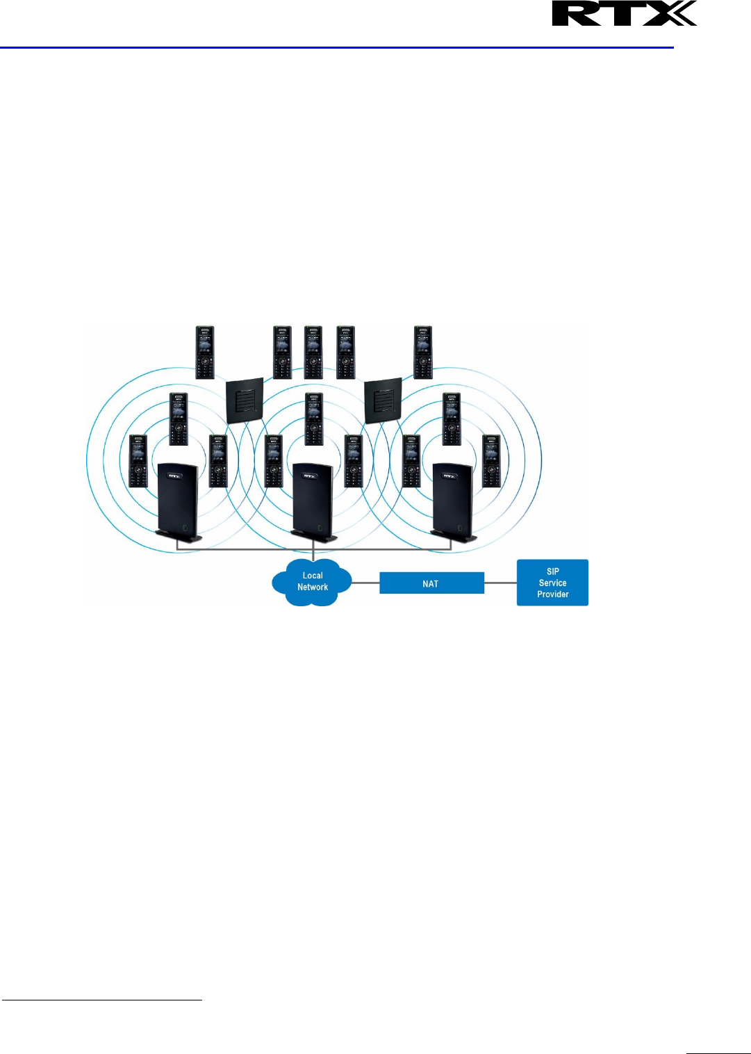
2 Introduction – System Overview
In a typical telephony system, the network setup is the interconnection between Base-stations, “fat”
routers, repeaters, portable parts, etc. The back-bone of the network depends on the deployment scenario
but a ring or hub topology is used. The network has centralized monitoring, and maintenance system.
The system is easy to scale up and supports from 1 to 50 bases in the same network. Further it is able to
support up to 1000 registered handsets (RTX8630, RTX8830 and RTX8430). The Small and Medium Scale
Enterprise (SME) VoIP system setup is illustrated below. Based on PoE interface each base station is easy to
install without additional wires other than the LAN cable. The system supports the IP DECT CAT-IQ repeater
RTX4024 with support up to 5 channels simultaneous call sessions.
The following figure gives a graphical overview of the architecture of the SME VoIP System:
2.1 Hardware Setup
SME network hardware setup can deployed as follows:
Base-station(s) are connected via Layer 3 and/or VLAN Aware Router depending on the deployment
requirements. The Layer 3 router implements the switching function.
The base-stations are mounted on walls or lamp poles so that each base-station is separated from each
other by up to 50m indoor
1
(300m outdoor). Radio coverage can extended using repeaters that are
installed with same distance to base-station(s). Repeaters are range extenders and cannot be used to solve
local call capacity issues. In this case additional bases must be used.
The base-station antenna mechanism is based on space diversity feature which improves coverage. The
base-stations uses complete DECT MAC protocol layer and IP media stream audio encoding feature to
provide up to 10 simultaneous calls.
1
Measured with European DECT radio and depends on local building layout and material

SME VoIP System Guide, Version 2.6
Proprietary and Confidential
Chapter: Introduction – System Overview
11
2.2 Components of SME VoIP System
RTX SME VoIP system is made up of (but not limited to) the following components:
• At least one RTX Base Station is connected over an IP network and using DECT as air-core interface.
• RTX IP DECT wireless Handset.
• RTX SME VoIP Configuration Interface; is a management interface for SME VoIP Wireless Solution. It
runs on all IP DECT Base stations. Each Base station has its own unique settings.
2.2.1 RTX Base Stations
The Base Station converts IP protocol to DECT protocol and transmits the traffic to and from the end-nodes
(i.e. wireless handsets) over a channel. It has 12 available channels.
In a multi-cell setup, each base station has:
• 8 channels have associated DSP resources for media streams.
• The remaining 4 channels are reserved for control signalling between IP Base Stations and the SIP/DECT
end nodes (or phones).
Base Stations are grouped into clusters. Within each Cluster, Base Stations are synchronized to enable a
seamless handover when a user moves from one base station coverage to another. For synchronization
purposes, it is not necessary for Base Stations to communicate directly with each other in the system. E.g. a
Base Station may only need to communicate with the next in the chain. It is advisable for a Base Station to
identify more than one Base Station to guarantee synchronization in the situation that one of the Base
Stations fails.
The 4 control signalling channels are used to carry bearer signals that enable a handset to initiate a
handover process.
2.2.2 SME VoIP Administration Server/Software
This server is referred to as SME VoIP Configuration Interface.
The SME VoIP Configuration Interface is a web based administration page used for configuration and
programming of the base station and relevant network end-nodes. E.g. handsets can be registered or de-
registered from the system using this interface.
The configuration interface can be used as a setup tool for software or firmware download to base stations,
repeaters and handsets. Further, it is used to check relevant system logs that can be useful to
administrator. These logs can be used to troubleshoot the system when the system faces unforeseen
operational issues.
2.2.3 RTX Wireless Handset
The handset is a lightweight, ergonomically and portable unit compatible with Wideband Audio (G.722),
DECT, GAP standard, CAT-iq audio compliant.
The handset includes Colour display with graphical user interface. It can also provide the subscriber with
most of the features available for a wired phone, in addition to its roaming and handover capabilities. Refer
to the relevant handset manuals for full details handset features.
2.3 Wireless Bands
The bands supported in the SME VoIP are summarized as follows:
Frequency bands: 1880 – 1930 MHz (DECT)
1880 – 1900 MHz (10 carriers) Europe/ETSI
1910 – 1930 MHz (10 carriers) LATAM
1920 – 1930 MHz (5 carriers) US

SME VoIP System Guide, Version 2.6
Proprietary and Confidential
Chapter: Introduction – System Overview
12
2.4 System Capacity (in Summary)
SME network capacity of relevant components can be summarised as follows:
Description
Capacity
Min ## of Bases Single Cell Setup
1
Max ## of Bases in Multi-cell Setup (configurable)
50/127/254
Single/Multi Cell Setup: Max ## of Repeaters
50 bases and 3 repeater per Base
127 bases and 1 repeater pr Base
254 bases and 0 repeaters
Multi-cell Setup: Total Max ## of Repeaters
100
Max ## of Users (SIP registrations) per Base
30
Max ## of Users per SME VoIP System
limited to 1000
Multi-cell Setup: Max ## of Synchronisation levels
24
Single Cell Setup: Max ## Simultaneous Calls
10 per Base station
Multi-cell Setup: Max ## of Calls
8 per Base station
Total Max ## Simultaneous Calls (Multi-cell Setup)
Limited to 1000
Repeater: Max ## of Calls (Narrow band)
5
Repeater: Max ## of Calls (G722)
2
Quick Definitions
Single Cell Setup: SME telephony network composed of one base station
Multi-cell Setup: Telephony network that consists of more than one base station
Synchronisation Level: Is the air core interface between two base stations.
2.5 Advantages of SME VoIP System
They include (but not limited to):
1. Simplicity. Integrating functionalities leads to reduced maintenance and troubleshooting, and significant
cost reductions.
2. Flexibility. Single network architecture can be employed and managed. Furthermore, the architecture is
amenable to different deployment scenarios, including Isolated buildings for in-building coverage, location
with co-located partners, and large to medium scale enterprises deployment for wide coverage.
3. Scalability. SME network architecture can easily be scaled to the required size depending on customer
requirement.
4. Performance. The integration of different network functionalities leads to the collapse of the protocol
stack in a single network element and thereby eliminates transmission delays between network elements
and reduces the call setup time and packet fragmentation and aggregation delays.
SME VoIP System Guide, Version 2.6
Proprietary and Confidential
Chapter: Installation of Base Stations/Repeater
13
3 Installation of Base Stations/Repeater
After planning the network, next is to determine the proper places or location the relevant base stations
will be installed. Therefore, we briefly describe the how to install the base station in this chapter.
3.1 Package – Contents/Damage Inspection
Before Package Is Opened:
Examine the shipping package for evidence of physical damage or mishandling prior to opening. If there is a
proof of mishandling prior to opening, you must report it to the relevant support centre of the regional
representative or operator.
Contents of Package:
Make sure all relevant components are available in the package before proceeding to the next step.
Every shipped base unit package/box contains the following items:
2 x mounting screws and 2 x Anchors
1 x Plastic stand
Base unit
Damage Inspection:
The following are the recommended procedure for you to use for inspection:
1. Examine all relevant components for damage.
2. Make a “defective on arrival – DOA” report or RMA to the operator. Do not move the shipping
carton until it has been examined by the operator. If possible send pictures of the damage. The
operator/regional representative will initiate the necessary procedure to process this RMA. They
will guide the network administrator on how to return the damaged package if necessary.
3. If no damage is found then unwrap all the components and dispose of empty package/carton(s) in
accordance with country specific environmental regulations.
SME VoIP System Guide, Version 2.6
Proprietary and Confidential
Chapter: Installation of Base Stations/Repeater
14
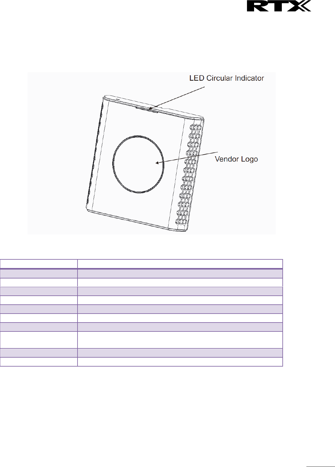
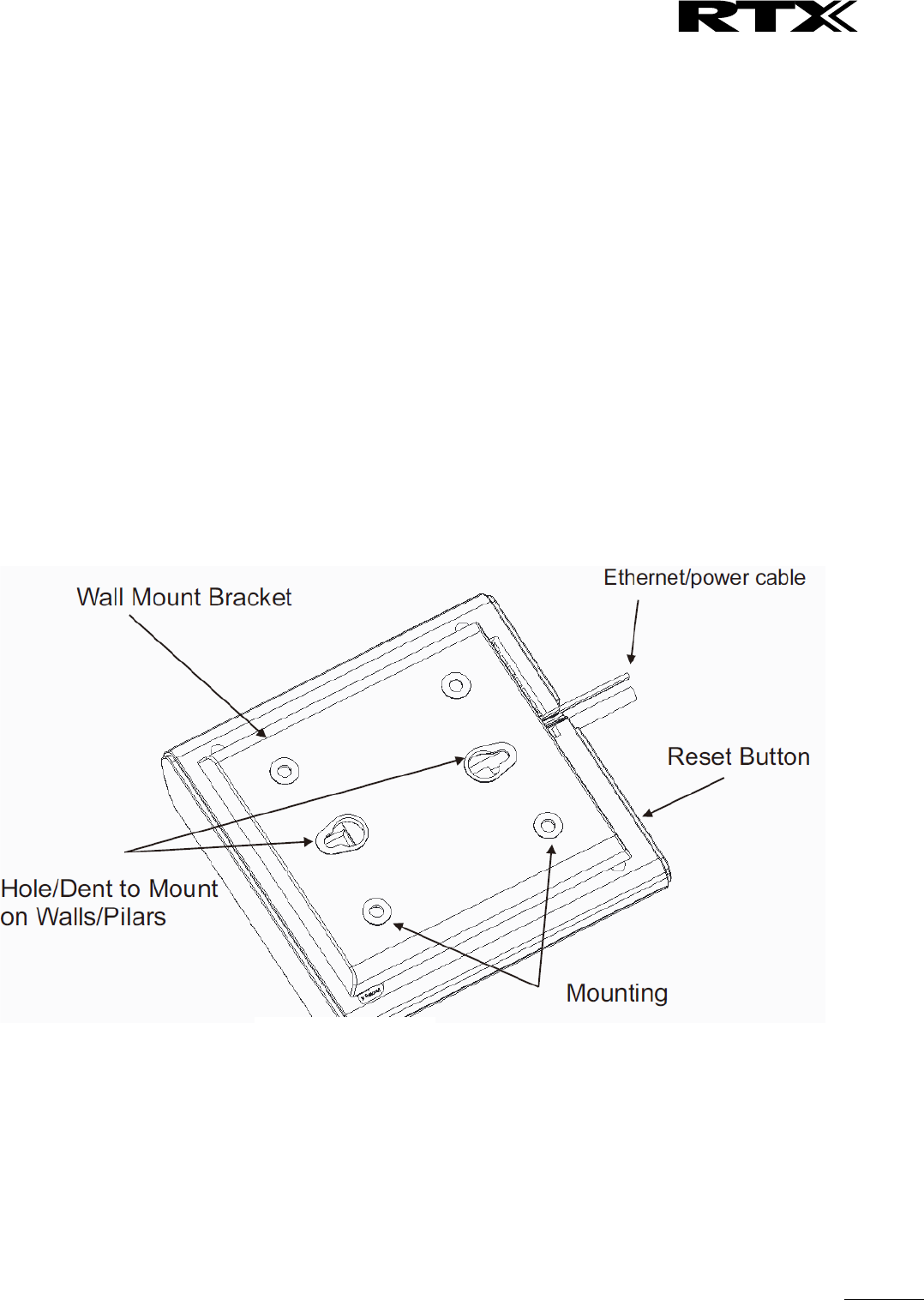
3.2 RTX Base station Mechanics
The base station front end shows an LED indicator that signals different functional states of the base unit
and occasionally of the overall network. The indicator is off when the base unit is not powered.
The table below summarises the various LED states:
LED State
State
Unlit
No power in unit
Unlit/Solid red
Error condition
Blinking green
Initialisation
Solid red
Factory reset warning or long press in BS reset button
Blinking red
Factory setting in progress
Solid green
Ethernet connection available (Normal operation)
Blinking red
Ethernet connect not available OR handset de/registration failed
Solid red
Critical error (can only be identified by RTX Engineers). Symptoms
include no system/SIP debug logs are logged, etc.
Orange
Press reset button of base station.
Blinking orange
No IP address received
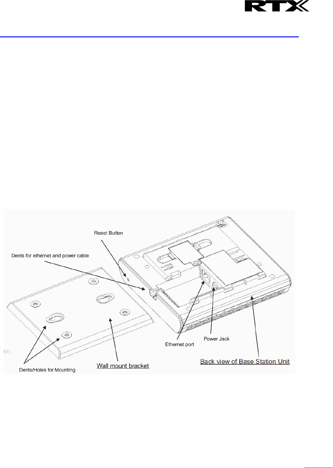
3.3 RTX Base Unit – Reset feature
It is possible to restart or reset the base station unit by pressing a knob at the rear side of the unit.
Alternatively, it can be reset from the SME Configuration Interface. We do not recommend this; but
unplugging and plugging the Ethernet cable back to the PoE port of the base station also resets the base
unit.
SME VoIP System Guide, Version 2.6
Proprietary and Confidential
Chapter: Installation of Base Stations/Repeater
15
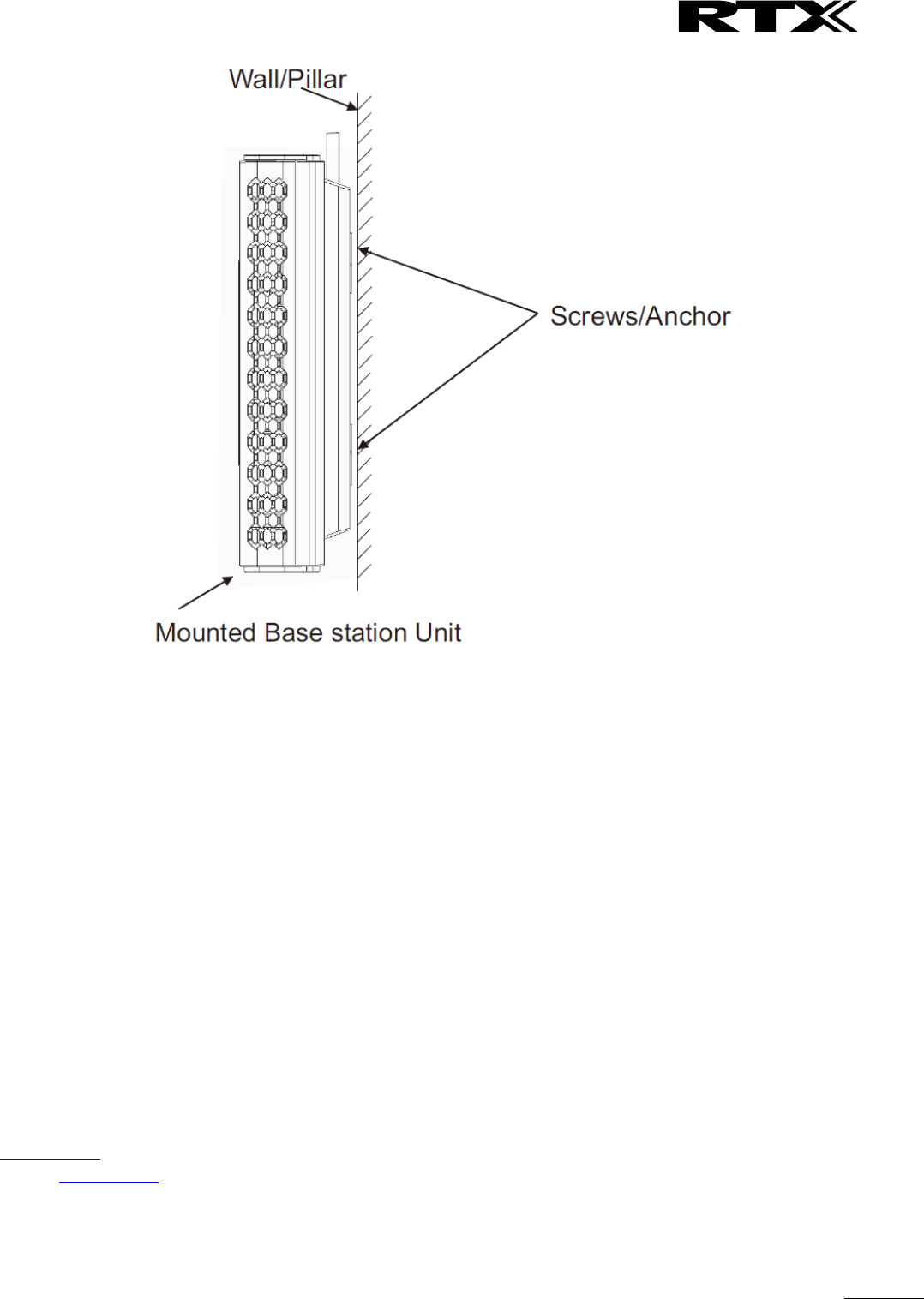
3.4 Installing the Base Station
First determine the best location that will provide an optimal coverage taking account the construction of
the building, architecture and choice of building materials.
Next, mount the Base Station on a wall to cover range between 50 – 300 meters (i.e. 164 to 984 feet),
depending whether it’s an indoor or outdoor installation. Please refer to chapter 10 for important
information regarding network requirements, deployment considerations, site planning, cell
coverage/capacity planning, environmental considerations and recommended Base station placement.
3.4.1 Mounting the Base Stations/Repeaters:
We recommend the base station be mounted an angle other than vertical on both concrete/wood/plaster
pillars and walls for optimal radio coverage. Avoid mounting the base units upside down as it significantly
reduces radio coverage.
Mount the base unit as high as possible to clear all nearby objects (e.g. office cubicles and cabinets, etc.).
Occasionally extend coverage to remote offices/halls with lower telephony users by installing Repeaters.
Make sure that when you fix the base stations with screws, the screws do not touch the PCB on the unit.
Secondly, avoid all contacts with any high voltage lines.
SME VoIP System Guide, Version 2.6
Proprietary and Confidential
Chapter: Installation of Base Stations/Repeater
16
3.5 Find IP of Base Station
To find IP of the installed base station two methods can be used; Using handset Find IP feature or browser
IPDECT feature.
3.5.1 Using handset Find IP feature
On the handset press “Menu” key followed by the keys: *47* to get the handset into find bases
menu. The handset will now scan for 8663 bases. Depending on the amount of powered on bases
with active radios and the distance to the base it can take up to minutes to find a base.
- Use the cursor down/up to select the base MAC address for the base
- The base IP address will be shown in the display
The feature is also used for deployment. For further details refer to reference [2].
3.5.2 Using browser IPDECT
Open any standard browser and enter the address:
http://ipdect<MAC-Address-Base-Station>
for e.g. http://ipdect00087B00AA10. This will retrieve the HTTP Web Server page from the base station
with hardware address 00087B00AA10.
This feature requires an available DNS server.
SME VoIP System Guide, Version 2.6
Proprietary and Confidential
Chapter: Installation of Base Stations/Repeater
17
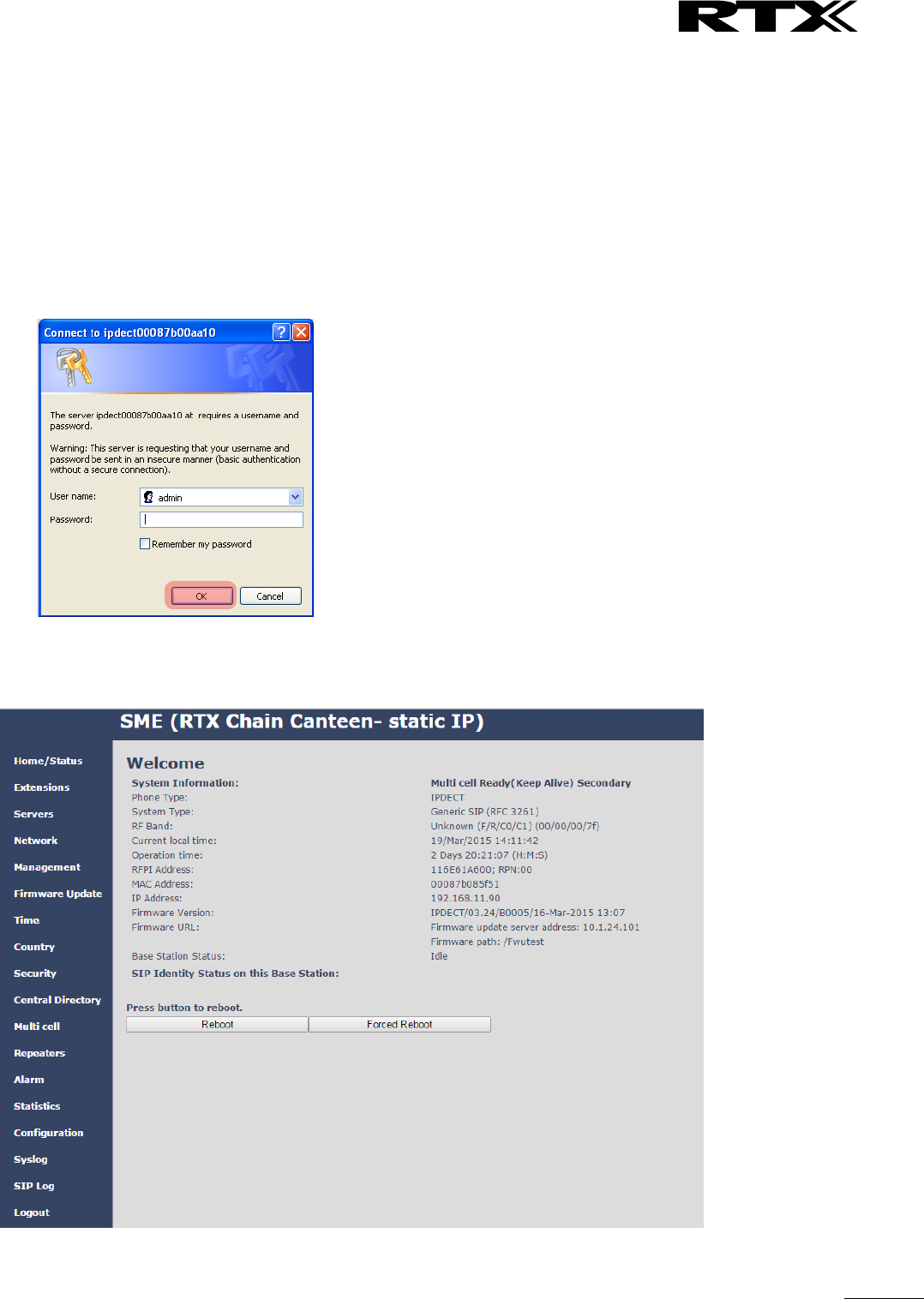
3.6 Login to Base SME Configuration Interface
STEP 1 Connect the Base station to a private network via standard Ethernet cable (CAT-5).
STEP 2 Use the IP find menu in the handset (Menu * 4 7 *) to determine the IP-address of the base
station by matching the MAC address on the back of the base station with the MAC address list in
the handset.
STEP 3 On the Login page, enter your authenticating credentials (i.e. username and password). By
default the username and password is admin. Click OK button.
STEP 4 Once you have authenticated, the browser will display front end of the SME Configuration
Interface. The front end will show relevant information of the base station.
SME VoIP System Guide, Version 2.6
Proprietary and Confidential
Chapter: Making Handset Ready
18
4 Making Handset Ready
In this chapter we briefly describe how to prepare the handset for use, install, insert and charge new
batteries. Please refer to an accompanying Handset User Guide for more information of the features
available in the Handset.
4.1 Package – Contents/Damage Inspection
Before Package Is Opened:
Examine the shipping package for evidence of physical damage or mishandling prior to opening. If there is a
proof of mishandling prior to opening, you must report it to the relevant support centre of the regional
representative or operator.
Contents of Package:
Make sure all relevant components are available in the package before proceeding to the next step.
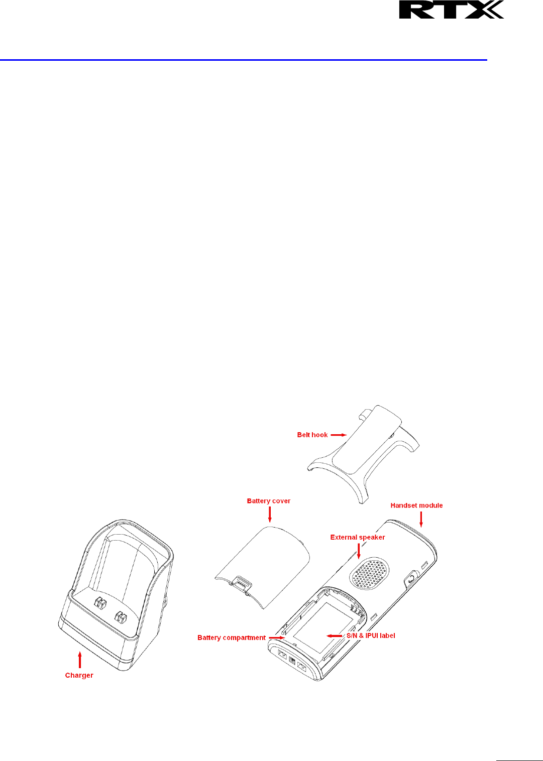
Every shipped base unit package/box contains the following items:
2 x mounting screws and 2 x Anchors
1 x Handset hook
1 x A/C Adaptor
1 x Battery
1 x charger
1 x Handset Unit, 1 x Battery cover

SME VoIP System Guide, Version 2.6
Proprietary and Confidential
Chapter: Making Handset Ready
19
Damage Inspection:
The following are the recommended procedure for you to use for inspection:
1. Examine all relevant components for damage.
2. Make a “defective on arrival – DOA” report or RMA to the operator. Do not move the shipping
carton until it has been examined by the operator. The operator/regional representative will
initiate the necessary procedure to process this RMA. They will guide the network administrator on
how to return the damaged package if necessary.
3. If no damage is found then unwrap all the components and dispose of empty package/carton(s) in
accordance with country specific environmental regulations.
4.2 Before Using the Phone
Here are the pre-cautions users should read before using the Handset:
Installing the Battery
1. Never dispose battery in fires, otherwise it will explode.
2. Never replace the batteries in potentially explosive environments, e.g. close to inflammable liquids/
gases.
3. ONLY use approved batteries and chargers from the vendor or operator.
4. Do not disassemble, customise or short circuit the battery
Using the Charger
Each handset is charged through the use of a handset charger. The charger is a compact desktop unit
designed to charge and automatically maintain the correct battery charge levels and voltage.
The charger Handset is powered by AC supply from 110-240VAC that supplies 5.5VDC at 600mA.
When charging the battery for the first time, it is necessary to leave the handset in the charger for at least
10 hours before the battery is fully charged and the handset ready for use.
Handset in the Charger
For correct charging, ensure that the room temperature is between 0°C and 25°C/32°F and 77°F. Do not
place the handset in direct sunlight. The battery has a built-in heat sensor which will stop charging if the
battery temperature is too high.
If the handset is turned off when placed in charger, only the LED indicates the charging. When handset is
turned off, the LED flashes at a low frequency while charging and lights constantly when the charging is
finished. There will be response for incoming calls.
If the handset is turned on when charging, the display shows the charging status.
Open Back Cover
1. Press down the back cover and slide it towards the bottom of the handset.
2. Remove Back Cover from Handset
SME VoIP System Guide, Version 2.6
Proprietary and Confidential
Chapter: Making Handset Ready
20
Handset Serial Number
The serial number (IPEI/IPUI number) of each handset is found either on a label, which is placed behind the
battery, or on the packaging label. First, lift off handset back cover and lift the battery and read the serial
number.
The serial number is needed to enable service to the handset. It must be programmed into the system
database via the SME VoIP Configuration interface.
Replace Battery
Remove Back Cover from Handset. Remove the old battery and replace with a new one.
4.3 Using the Handset
Please refer handset manual for detailed description of how to use the handset features [1].
SME VoIP System Guide, Version 2.6
Proprietary and Confidential
Chapter: SME VoIP Administration Interface
21
5 SME VoIP Administration Interface
The SME VoIP Administration Interface is also known as SME VoIP Configuration. It is the main interface
through which the system is managed and debugged.
The SME VoIP Configuration Interface is an in-built HTTP Web Server service residing in each base station.
This interface is a user friendly interface and easy to handle even to a first time user.
Note: Enabling secure web is not possible. For secure configuration use secure provisioning.
This chapter seeks to define various variables/parameters available for configuration in the network.
5.1 Web navigation
We describe the left menu in the front end of the SME VoIP Administration Interface.
Feature
Description
Home/Status
This is the front end of the Base station’s HTTP web interface. This page shows the
summary of current operating condition and settings of the Base station and
Handset(s).
Extensions
Administration of extensions and handsets in the system

SME VoIP System Guide, Version 2.6
Proprietary and Confidential
Chapter: SME VoIP Administration Interface
22
Servers
On this page the user can define which SIP/NAT server the network should connect
to.
Network
Typically the user configures the Network settings from here.
NAT provisioning: allows configuration of features for resolving of the NAT –
Network Address Translation. These features enable interoperability with most
types of routers.
DHCP: allows changes in protocol for getting a dynamic IP address.
Virtual LAN: specifies the Virtual LAN ID and the User priority.
IP Mode: specifies using dynamic (DHCP) or static IP address for your SME network.
IP address: if using DHCP leave it empty. Only write in, when you use static IP
address.
Subnet mask: if using DHCP, leave it empty. Only write in, when you use static IP
address.
DNS server: specify if using DHCP, leave it empty. Only write in the DNS server
address of your Internet service provider, when you use static IP address. (DNS =
Dynamic Name Server)
Default gateway: if using DHCP, leave it empty. Write in the IP address of your
router, when you use static IP address.
Management
Defines the Configuration server address, Management transfer protocol, sizes of
logs/traces that should be catalogued in the system.
Firmware
Update
Remote firmware updates (HTTP(s)/TFTP) settings of Base stations and handsets.
Time
Here the user can configure the Time server. It should be used as time server in
relevant country for exact time. The time servers have to deliver the time to
conform to the Network Time Protocol (NTP). Handsets are synchronised to this
time. Base units synchronise to the master using the Time server.
Country
Specifying the country/territory where the SME network is located ensures that
your phone connection functions properly.
Note: The base language and country setting are independent of each other.
Security
The users can administrate certificates and create account credentials with which
they can log in or log out of the embedded HTTP web server.
Central
Directory
Interface to common directory load of up to 3000 entries using *csv format or
configuration of LDAP directory.
Note: LDAP and central directory cannot operate at the same time.
Multi cell
Specify to connect base station or chain of base stations to the network. Make sure
the system ID for the relevant base stations are the same otherwise the multi-cell
feature will not work.
Repeaters
Administration and configuration of repeaters of the system
Alarm
Administration and configuration of the alarm settings on the system. This controls
the settings for alarms that can be sent to the handsets. This feature is only
available on certain types of handsets.
Statistics
Overview of system and call statistics for a system.
Configuration
This shows detail and complete SME network settings for base station(s),
HTTP/DNS/DHCP/TFTP server, SIP server, etc.
Syslog
Overall network related events or logs are displayed here (only live feed is shown).
SIP Log
SIP related logs can be retrieved from url link. It is also possible to clear logs from
this feature.
SME VoIP System Guide, Version 2.6
Proprietary and Confidential
Chapter: SME VoIP Administration Interface
23
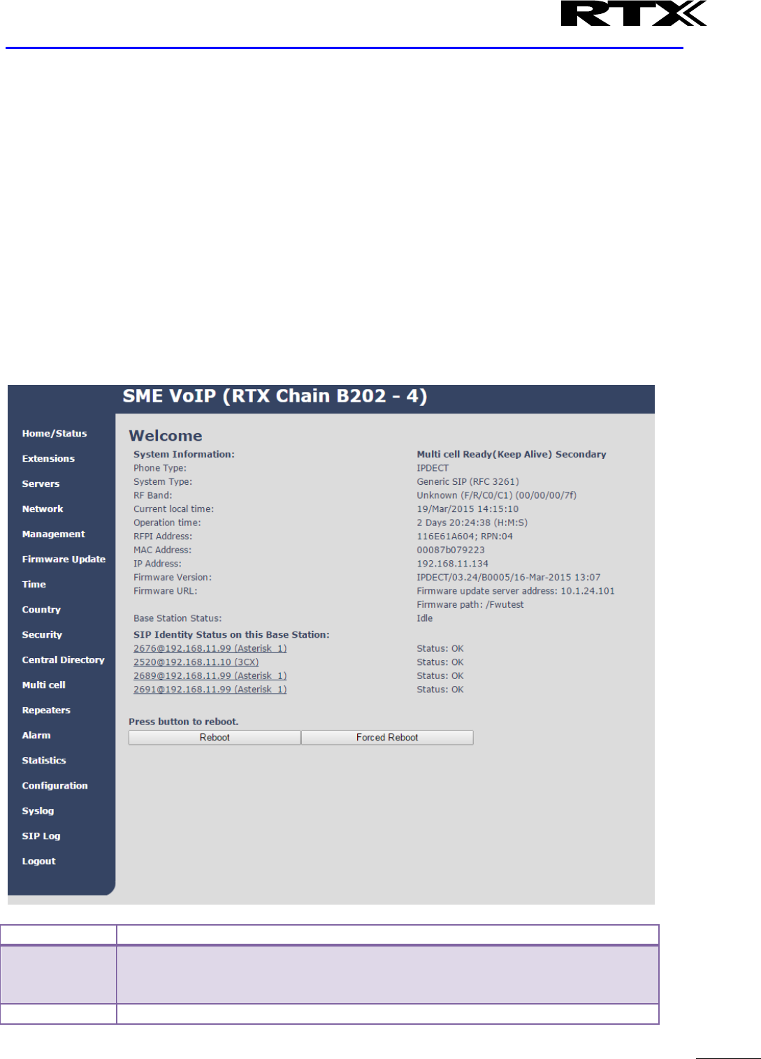
5.2 Home/Status
We describe the parameters found in the Welcome front end home/status of the SME VoIP Administration
Interface.
Screenshot
Parameter
Description
System information
This base current multi-cell state
Phone Type
Always IPDECT
System Type
This base customer configuration
RF Band
This base RF band setting.
The parameter is defined in production and relates to the radio approvals
shown on the label of the base.
Current local time
This base local time
Operation time
Operation is operation time for the base since last reboot
RFPI-Address
This base RFPI address
MAC-Address
This base MAC address
IP-Address
This base IP address
Firmware version
This base firmware version
Firmware URL
Firmware update server address and firmware path on server
Base Station Status
“Idle” : When no calls on base
“In use” : When active calls on base
SIP identity status
List of extensions present at this base station.
Format: “extension”@“this base IP address”(“server name”) followed by
status to the right. Below is listed possible status:
OK: Handset is ok
SIP Error: SIP registration error
Reboot
Reboot after all connections is stopped on base. Connections are active
calls, directory access, firmware update active
Forced Reboot
Reboot immediately.
SME VoIP System Guide, Version 2.6
Proprietary and Confidential
Chapter: SME VoIP Administration Interface
24
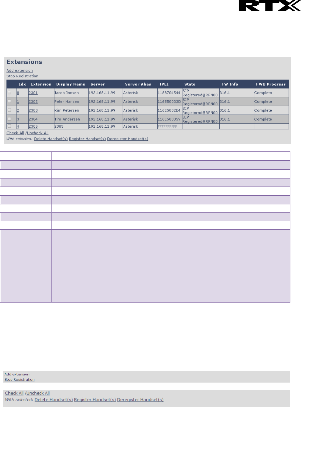
5.3 Extensions
In this section, we describe the different parameters available whenever the administrator is creating
extensions for handsets. Note, it is not possible to add extensions if no servers are defined. As well the
section describes the administration of extensions and handsets using the extension list and the extension
list menu.
Software supports customer configurations with and without the multiline feature. Section 5.3.1 describes
“add extensions” without multiline and 5.3.2 with “multiline”.
The system can handle maximum 1000 extensions matching 1000 handsets which can be divided between
servers. When 1000 handsets are registered it is not possible to add more extensions. With active multiline
feature the system can handle maximum 1000 extensions. With 4 active lines in multiline maximum 200
handsets can be active in the system.
Note: Within servers or even with multi servers, extensions must always be unique. This means same
extension number on server 1 cannot be re-used on server 2.
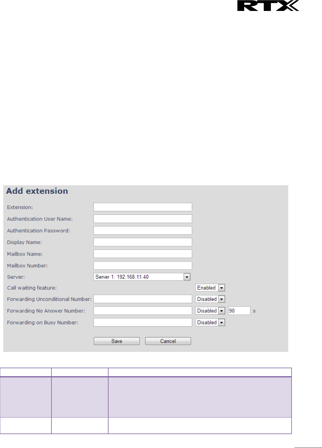
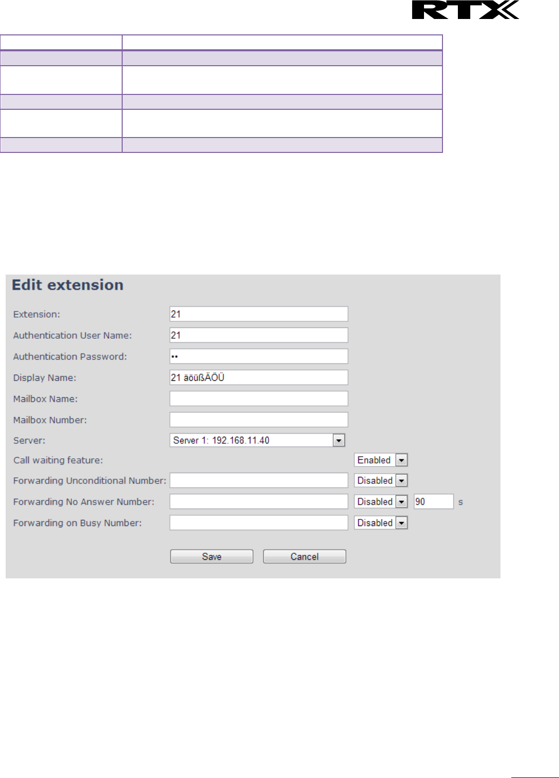
5.3.1 Add extension (no multiline)
Screenshot
Parameter
Default Value(s)
Description
Extension
Empty
Handset phone number or SIP username depending on the setup.
Possible value(s): 8-bit string length
Example: 1024, etc.
Note: The Extension must also be configured in SIP server in order
for this feature to function.
Authentication
User Name
Empty
Username: SIP authentication username
Permitted value(s): 8-bit string length

SME VoIP System Guide, Version 2.6
Proprietary and Confidential
Chapter: SME VoIP Administration Interface
25
Authentication
Password
Empty
Password: SIP authentication password.
Permitted value(s): 8-bit string length
Display Name
Empty
Human readable name used for the given extension
Permitted value(s): 8-bit string length
Mailbox Name
Empty
Name of centralised system used to store phone voice messages
that can be retrieved by recipient at a later time.
Valid Input(s): 8-bit string Latin characters for the Name
Mailbox
Number
Empty
Dialled mail box number by long key press on key 1.
Valid Input(s): 0 – 9, *, #
Note: Mailbox Number parameter is available only when it’s
enabled from SIP server.
Server
Server 1 IP
FQDN or IP address of SIP server.
Drop down menu to select between the defined Servers of SME
VoIP Service provider.
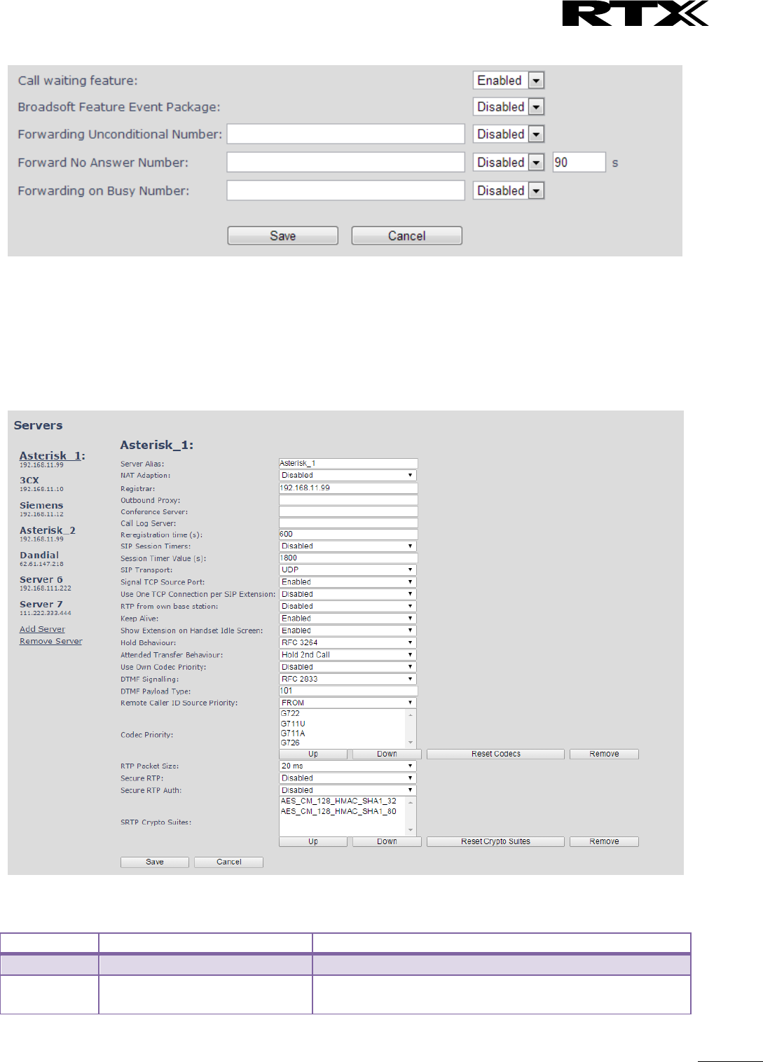
Call waiting
feature:
Enabled
Used to enable/disable Call Waiting feature. When disabled a
second incoming call will be rejected. If enabled a second call will
be presented as call waiting.
Broadsoft
Feature Event
Package
Disabled
If enabled the given SIP extension subscribes for the Broadsoft
Application Server Feature Event Package, and it becomes ready
for reception of SIP NOTIFY with status on the following Broadsoft
Server Services:
-Do Not Disturb
-Call Forwarding (Always, Busy, No answer)
The received status will be displayed in the handset idle display.
Reference section 5.3.3
Forwarding
Unconditional
Number
Empty
Number to which incoming calls must be re-routed to irrespective
of the current state of the handset.
Forwarding Unconditional must be enabled to function.
Note: Feature must be enabled in the SIP server before it can
function in the network
Disabled
Forwarding No
Answer Number
Empty
Number to which incoming calls must be re-routed to when there
is no response from the SIP end node.
Forwarding No Answer Number must be enabled to function.
Note: Feature must be enabled in the SIP server before it can
function in the network
Specify delay from call to forward in seconds.
Disabled
90
Forwarding On
Busy Number
Empty
Number to which incoming calls must be re-routed to when SIP
node is busy.
Forwarding On Busy Number must be enabled to function.
Note: Feature must be enabled in the SIP server before it can
function in the network
Disabled
SME VoIP System Guide, Version 2.6
Proprietary and Confidential
Chapter: SME VoIP Administration Interface
26
5.3.1.1 Extensions list (no multiline)
The added extensions will be shown in the extension lists.
The list can be sorted by any of the top headlines, by mouse click on the headline link.
Parameter
Description
Idx
Select / deselect for delete, register and deregister handsets
Extension
Given extension is displayed
Display Name
Given display name is displayed. If no name given this field will be empty
Server
Server IP or URL
Server Alias
Given server alias is displayed. If no alias given this field will be empty.
IPEI
Handset IPEI. IPEI is unique DECT identification number.
State
SIP registration state – if empty the handset is not SIP registered.
FW info
Firmware version of handset
FWU Progress
Possible FWU progress states:
Off: Means sw version is specified to 0 = fwu is off
Initializing: Means FWU is starting and progress is 0%.
X% : FWU ongoing
Verifying X%: FWU writing is done and now verifying before swap
”Waiting for charger” (HS) / ”Conn. term. wait” (Repeater): All FWU is complete and
is now waiting for handset/repeater restart.
Complete HS/repeater: FWU complete
Error: Not able to fwu e.g. file not found, file not valid etc
5.3.1.2 Handset and extension list top/sub-menus
The handset extension list menu is used to control paring or deletion of handset to the system (DECT
registration/de-registrations) and to control SIP registration/de-registrations to the system.
Above and below the list are found commands for making operations on handsets/and extensions. The top
menu is general operations, and the sub menu is always operating on selected handsets/extensions.
Screenshots
In the below table each command is described.
SME VoIP System Guide, Version 2.6
Proprietary and Confidential
Chapter: SME VoIP Administration Interface
27
Actions
Description
Add extension
Access to the “Add extension” sub menu
Stop Registration
Manually stop DECT registration mode of the system. This prevents
any handset from registering to the system
Delete Handset(s)
Deregister selected handset(s), but do not delete the extension(s).
Register Handset(s)
Enable registration mode for the system making it possible to
register at a specific extension (selected by checkbox)
Deregister Handset(s)
Deregister the selected handset(s) and delete the extension(s).
Note: By power off the handset the handset will SIP deregister the PBX.
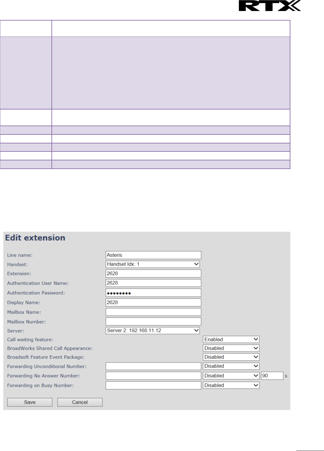
5.3.1.3 Edit Extension (no multiline)
To edit extension use the mouse to click the link of the extension.
Screenshot
SME VoIP System Guide, Version 2.6
Proprietary and Confidential
Chapter: SME VoIP Administration Interface
28
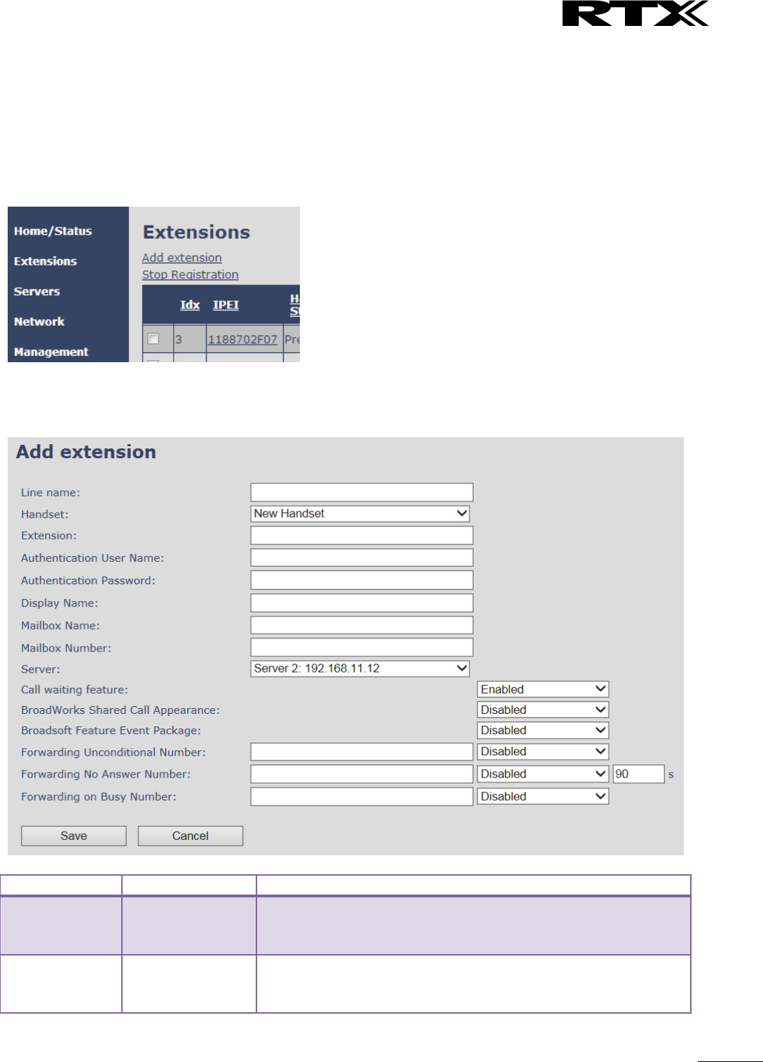
5.3.2 Multiline: Add extension
With active multiline feature the system distinguish between extensions, physical handsets and maximum 4
lines.
To add a physical handset first an extension must be available. The “add extension” is available from the
Extension web top.
Screenshot
By pressing the link the “add extension” menu will appear. In the following the parameters are explained.
Screenshot
Parameter
Default Value(s)
Description
Line Name
Empty
Name of line shown to be used to show from which line the
incoming call is coming and used when user must select from
which line to make outgoing call.
Handset
New Handset
The extension must be associated to a handset. By default a new
handset can be configured, alternatively the user can select an
already existing handset Idx.

SME VoIP System Guide, Version 2.6
Proprietary and Confidential
Chapter: SME VoIP Administration Interface
29
Extension
Empty
Handset phone number or SIP username depending on the setup.
Possible value(s): 8-bit string length
Example: 1024, etc.
Note: The Extension must also be configured in SIP server in order
for this feature to function.
Authentication
User Name
Empty
Username: SIP authentication username
Permitted value(s): 8-bit string length
Authentication
Password
Empty
Password: SIP authentication password.
Permitted value(s): 8-bit string length
Display Name
Empty
Human readable name used for the given extension
Permitted value(s): 8-bit string length
Mailbox Name
Empty
Name of centralised system used to store phone voice messages
that can be retrieved by recipient at a later time.
Valid Input(s): 8-bit string Latin characters for the Name
Mailbox
Number
Empty
Dialled mail box number by long key press on key 1.
Valid Input(s): 0 – 9, *, #
Note: Mailbox Number parameter is available only when it’s
enabled from SIP server.
Server
Server 1 IP
DNS or IP address of SIP server.
Drop down menu to select between the defined Servers of SME
VoIP Service provider.
Call waiting
feature
Enabled
Used to enable/disable Call Waiting feature. When disabled a
second incoming call will be rejected. If enabled a second call will
be presented as call waiting.
BroadWorks
Shared Call
Appearance
Disabled
If enabled the given SIP extension is considered part of a
BroadWorks shared call appearance group (SCA). This enables the
Shared Call Appearance Settings section on the Handset page for
the handset that the extension is connected to.
Note: BroadWorks SCAs and their respective extensions must be
configured in the BroadWorks application server web interface
prior to being added on this page. The extension entered here
must match the extension configured in BroadWorks.
Broadsoft
Feature Event
Package
Disabled
If enabled the given SIP extension subscribes for the Broadsoft
Application Server Feature Event Package, and it becomes ready
for reception of SIP NOTIFY with status on the following Broadsoft
Server Services:
-Do Not Disturb
-Call Forwarding (Always, Busy, No answer)
The received status will be displayed in the handset idle display.
Forwarding
Unconditional
Number
Empty
Number to which incoming calls must be re-routed to irrespective
of the current state of the handset.
Forwarding Unconditional must be enabled to function.
Note: Feature must be enabled in the SIP server before it can
function in the network
Forwarding No
Answer Number
Disabled
Number to which incoming calls must be re-routed to when there
is no response from the SIP end node.
Forwarding No Answer Number must be enabled to function.
Note: Feature must be enabled in the SIP server before it can
function in the network
Specify delay from call to forward in seconds.
Empty
SME VoIP System Guide, Version 2.6
Proprietary and Confidential
Chapter: SME VoIP Administration Interface
30
Forwarding On
Busy Number
Disabled
Number to which incoming calls must be re-routed to when SIP
node is busy.
Forwarding On Busy Number must be enabled to function.
Note: Feature must be enabled in the SIP server before it can
function in the network
90
Empty
The location selection feature, which is available in the add extension screen in non-multiline mode, is
moved to edit handset from the handset and extension list. Edit handset screen is found by pressing the
handset IPEI link.
Screenshot
Then maximum extensions supported per handset are 4. There are no restrictions for adding more, but only
the first four will attempt to SIP register.
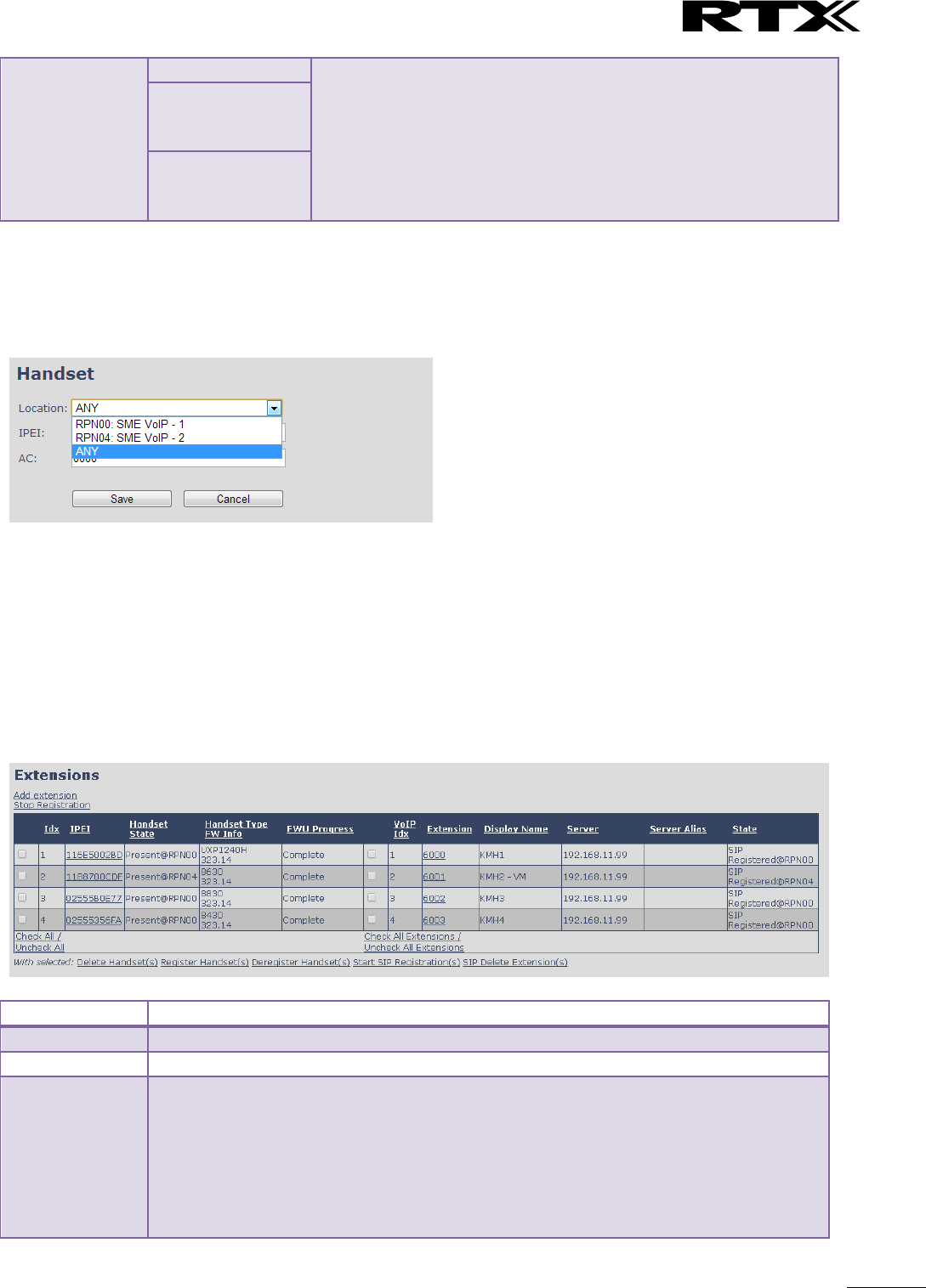
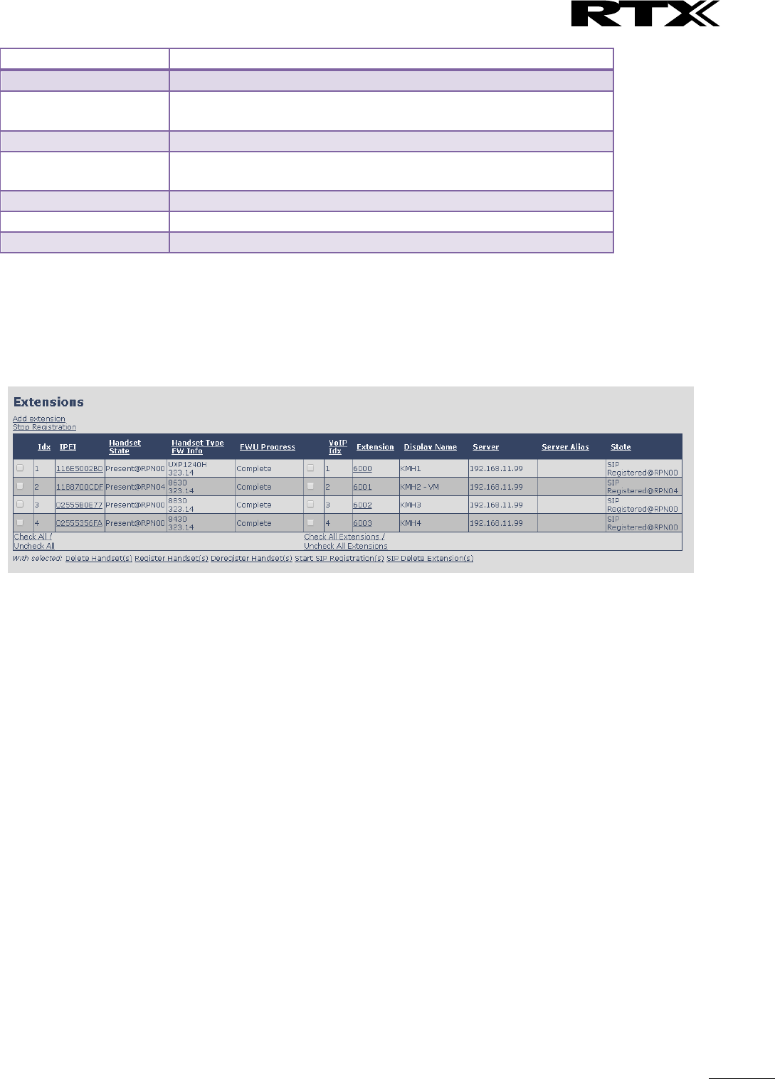
5.3.2.1 Multiline: Handset and extensions list
Added handset and extensions will be shown in the extension list.
The extension list is the access to the handset location control and the edit extension feature.
The list can be sorted by any of the top headlines, by mouse click on the headline link.
Screenshot
Parameter
Description
Idx
Index of handsets
IPEI
Handset IPEI. IPEI is unique DECT identification number.
Handset State
The state of the given handset:
Present@RPNxx: The handset is DECT located at the base with RPNxx
Detached: The handset is detached from the system (e.g. powered off)
Located: The handset is configured to locate on a specific base, but is has not been
possible to do so (e.g if the base is powered off)
Removed: The handset has been out of sight for a specified amount of time (~one
hour).
SME VoIP System Guide, Version 2.6
Proprietary and Confidential
Chapter: SME VoIP Administration Interface
31
Handset Type
FW Info
Name of the handset type
Firmware version of handset
FWU Progress
Possible FWU progress states:
Off: Means sw version is specified to 0 = fwu is off
Initializing: Means FWU is starting and progress is 0%.
X% : FWU ongoing
Verifying X%: FWU writing is done and now verifying before swap
”Waiting for charger” (HS) / ”Conn. term. wait” (Repeater): All FWU is complete and
is now waiting for handset/repeater restart.
Complete HS/repeater: FWU complete
Error: Not able to fwu e.g. file not found, file not valid etc
VoIP Idx
Index of the configured SIP extensions. Select/deselect to start SIP registration or
delete extension.
Extension
Given extension is displayed
Display Name
Given display name is displayed. If no name given this field will be empty
Server
Server IP or URL
Server Alias
Given server alias is displayed. If no alias given this field will be empty.
State
SIP registration state – if empty the handset is not SIP registered.
5.3.2.2 Multiline: Edit Extension
To edit extension use the mouse to click the link of the extension. Basically the same options are available
for edit extension as for add extension.
Screenshot
SME VoIP System Guide, Version 2.6
Proprietary and Confidential
Chapter: SME VoIP Administration Interface
32
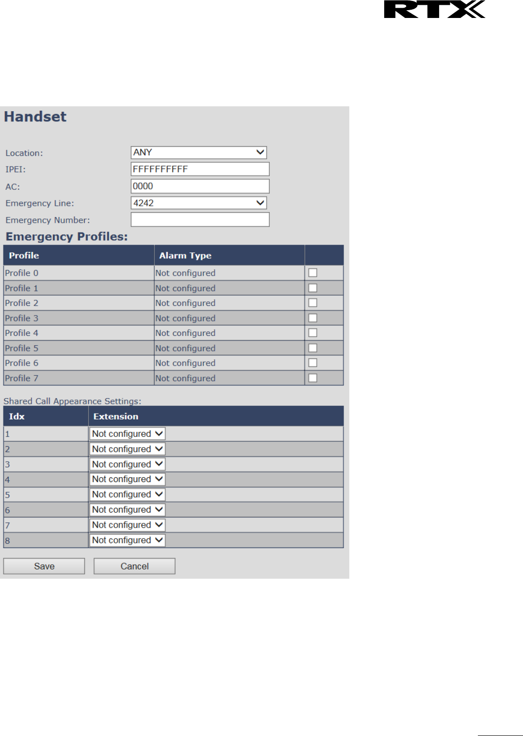
5.3.2.3 Multiline: Edit handset
Use the mouse to click the handset IPEI link to open the handset edit window. In the handset edit view the
handset SIP location can be fixed to either any or a specific base.
Screenshot
SME VoIP System Guide, Version 2.6
Proprietary and Confidential
Chapter: SME VoIP Administration Interface
33
Parameter
Default Value(s)
Description
Location
ANY
Specify a handset to be located at a specific base station or ANY
base station. A location of a handset controls the DECT registration
and the SIP registrations. Binding a handset to a specific base will
bind the SIP registrations to this base.
IPEI
Handset IPEI
Shows the handset IPEI. For an already registered handset
changing the IPEI will deregister the handset at next handset
location update.
AC
Handset AC code
Shows the handset AC code. AC code is used at handset
registration. Changing the AC code for an already registered
handset will have no effect.
Alarm Line
No Alarm Line
Selected
The line of multilines to be used for alarm call feature
Alarm Number
Empty
Number to be dialled in case of handset alarm key is pressed (Long
keypress > 3 seconds on navigation center key )
Alarm Profiles
Not configured
Check the wanted alarm profiles for the particular handset.
Shared Call
Appearance
Settings
Not configured
Each of the eight rows in the table represents an SCA status LED
on the handset Idle screen. For each row it is possible to specify
which shared line an LED should display the state of.
Only shared lines can be selected, that is, only extensions
defined for the handset for which BroadWorks Shared Call
Appearance is enabled are included in the selector.
A shared line can be reused for several LEDs. Each LED
with the same shared line then corresponds to different
appearance-indexes for that line (1 LED = appearance-
index 1, 2 LEDs = appearance-indexes 1 and 2, and so on).
It is not necessary to select a shared line for all of the LEDs. If an
LED is not assigned a line, its position on the screen is simply
empty.
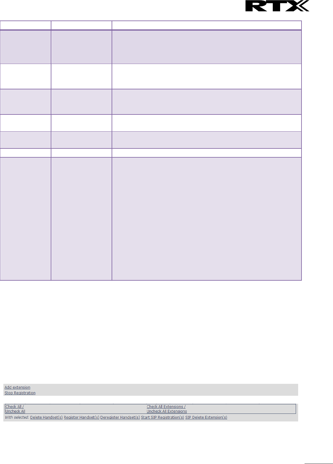
5.3.2.4 Multiline: Handset and extension list top/sub-menus
The handset extension list menu is used to control paring or deletion of handset to the system (DECT
registration/de-registrations) and to control SIP registration/de-registrations to the system.
Above and below the list are found commands for making operations on handsets/and extensions. The top
menu is general operations, and the sub menu is always operating on selected handsets/extensions.
Screenshots
In the below table each command is described.
SME VoIP System Guide, Version 2.6
Proprietary and Confidential
Chapter: SME VoIP Administration Interface
34
Actions
Description
Add extension
Access to the “Add extension” sub menu
Stop Registration
Manually stop DECT registration mode of the system. This prevents
any handset from registering to the system
Delete Handset(s)
Deregister selected handset(s), but do not delete the extension(s).
Register Handset(s)
Enable registration mode for the system making it possible to
register at a specific extension (selected by checkbox)
Deregister Handset(s)
Deregister the selected handset(s) and delete the extension(s).
Start SIP Registration(s)
Manually start SIP registration for selected handset(s).
SIP Delete Extension(s)
Deregister the selected handset(s) and delete the extension(s).
After creation of extensions check the handset Idx and click “Register Handset(s)” to DECT register the
handset to the base. First SIP registration is made by the system automatically by the handset DECT
registration procedure. For new extensions click “Start SIP Registration(s)” to SIP register the extensions to
the defined server.
Screenshot
Use the same procedure for other handsets, where the reference is the idx. no. when adding new
extensions to existing handsets.
5.3.3 Broadsoft Feature Event Package
If enabled the given SIP extension subscribes for the Broadsoft Application Server Feature Event Package,
and it becomes ready for reception of SIP NOTIFY with status on the following Broadsoft Server Services:
-Do Not Disturb
-Call Forwarding (Always, Busy, No answer)
The received status will be displayed in the handset idle display.
After pressing save the extension screen will appear with removed configuration option for the forward
feature as shown in the below picture.
Note: Call forwarding can as well be configured from the handset by the user (for operation refer to the
handset guide).
SME VoIP System Guide, Version 2.6
Proprietary and Confidential
Chapter: SME VoIP Administration Interface
35
Screenshot
5.4 Servers
In this section, we describe the different parameters available in the Servers configurations menu.
Maximum 10 servers can be configured.
Screenshot
Parameter
Default value
Description
Server Alias
Empty
Parameter for server alias
NAT
Adaption
Disabled
To ensure all SIP messages goes directly to the NAT
gateway in the SIP aware router.

SME VoIP System Guide, Version 2.6
Proprietary and Confidential
Chapter: SME VoIP Administration Interface
36
If the system receives a SIP response to a REGISTER
request with a “Via” header that includes the “received”
parameter (ex: “Via: SIP/2.0/UDP
10.1.1.1:4540;received=68.44.20.1”), the base will adapt
its contact information to the IP address from the
“received” parameter. Thus, the base will issue another
REGISTER request with the updated contact information.
If NAT Adaption is disabled, the “received” parameter is
ignored.
Registrar
Empty
SIP Server proxy DNS or IP address
Permitted value(s): AAA.BBB.CCC.DDD:<Port-Number> or
<URL>:<Port-Number>
Note: Specifying the Port Number is optional.
Outbound
Proxy
Empty
This is a Session Border Controller DNS or IP address (OR
SIP server outbound proxy address)
Set the Outbound proxy to the address and port of
private NAT gateway so that SIP messages sent via the
NAT gateway.
Permitted value(s): AAA.BBB.CCC.DDD or <URL> or
<URL>:<Port-Number>
Examples: “192.168.0.1”, “192.168.0.1:5062”,
“nat.company.com” and “sip:nat@company.com:5065”.
If empty call is made via Registar.
Conference
Server
Empty
Broadsoft conference feature.
Set the IP address of the conference server.
In case an IP is specified pressing handset conference will
establish a connection to the conference server.
If the field is empty the original 3-party local conference
on 8630 is used.
Call Log
Server
Empty
Broadsoft call log feature.
Set the IP address of the XSI call log server.
In case an IP is specified pressing handset will use the call
log server.
If the field is empty the local call log is used
Re-
registration
time
600
The “expires” value 36nalyse36n in SIP REGISTER
requests. This value indicates how long the current SIP
registration is valid, and hence is specifies the maximum
time between SIP registrations for the given SIP account.
Permitted value(s): A value below 60 sec is not
recommended, Maximum value 65636
SIP Session
Timers:
Disabled
RFC 4028. A “keep-alive” mechanism for calls. The session
timer value specifies the maximum time between “keep-
alive” or more correctly session refresh signals. If no
session refresh is received when the timer expires the call
will be terminated.
Default value is 1800 s according to the RFC. Min: 90 s.
Max: 65636.
If disabled session timers will not be used.
Session
Timer Values
(s):
1800
Default value is 1800s according to the RFC.
If disabled session timers will not be used.
Permitted value(s): Minimum value 90, Maximum 65636

SME VoIP System Guide, Version 2.6
Proprietary and Confidential
Chapter: SME VoIP Administration Interface
37
SIP Transport
UDP
Select UDP, TCP, TLS 1.0
Signal TCP
Source Port
Disabled
When SIP Transport is set to TCP or TLS, a TCP (or TLS)
connection will be established for each SIP extension.
The source port of the connection will be chosen by the
TCP stack, and hence the local SIP port parameter,
specified within the SIP/RTP Settings (see 5.5.5) will not
be used. The “Signal TCP Source Port” parameter
specifies if the used source port shall be signaled
explicitly in the SIP messages.
Use One
TCP/TLS
Connection
per SIP
Extension:
Disabled
When using TCP or TLS as SIP transport, choose if a
TCL/TLS connection
shall be established for each SIP extension or if the base
station shall establish one connection which all SIP
extensions use. Please note that if TLS is used and SIP
server requires client authentication (and requests a
client certificate), this setting must be set to disabled.
0: Disabled. (Use one TCP/TLS connection for all SIP
extensions)
1: Enabled. (Use one TCP/TLS connection per SIP
extensions).
RTP from
own base
station:
Disabled
If disabled RTP stream will be send from the base, where
the handset is located. By enable the RTP stream will
always be send from the base, where the SIP registration
is made.
This setting is typically enabled for operation with Cisco.
Keep Alive
Enabled
This directive defines the window period (30 sec.) to
keep opening the port of relevant NAT-aware router(s),
etc.
Show
Extension on
Handset Idle
Screen
Enabled
If enabled extension will be shown on handset idle
screen.
Hold
Behaviour
RFC 3264
Specify the hold behaviour by handset hold feature.
RFC 3264: Hold is signalled according to RFC 3264, i.e. the
connection information part of the SDP contains the IP
Address of the endpoint, and the direction attribute is
sendonly, recvonly or inactive dependant of the context
RFC 2543: The ”old” way of signalling HOLD. The
connection information part of the SDP is set to 0.0.0.0,
and the direction attribute is sendonly, recvonly or
inactive dependant of the context
Attended
Transfer
Behaviour
Hold 2nd Call
When we have two calls, and one call is on hold, it is
possible to perform attended transfer. When the transfer
soft key is pressed in this situation, we have traditionally
also put the active call on hold before the SIP REFER
request is sent. However, we have experienced that some
PBXes do not expect that the 2nd call is put on hold, and
therefore attended transfer fails on these PBXes.
The "Attended Transfer Behavior" feature defines
whether or not the 2nd call shall be put on hold before
the REFER is sent.

SME VoIP System Guide, Version 2.6
Proprietary and Confidential
Chapter: SME VoIP Administration Interface
38
If "Hold 2nd Call" is selected, the 2nd call will be held
before REFER is sent.
If "Do Not Hold 2nd Call" is selected, the 2nd call will not
be held before the REFER is sent
Use Own
Codec
Priority
Disabled
Default disabled.
By enable the system codec priority during incoming call
is used instead of the calling party priority.
E.g. If base has G722 as top codec and the calling party
has Alaw on top and G722 further down the list, the
G722 will be chosen as codec for the call.
DTMF
Signalling
RFC 2833
Conversion of decimal digits (and ‘*’ and ‘#’) into sounds
that share similar characteristics with voice to easily
traverse networks designed for voice
SIP INFO: Carries application level data along SIP
signalling path (e.g.: Carries DTMF digits generated
during SIP session OR sending of DTMF tones via data
packets in the same internet layer as the Voice Stream,
etc.).
RFC 2833: DTMF handling for gateways, end systems and
RTP trunks (e.g.: Sending DTMF tones via data packets in
different internet layer as the voice stream)
Both: Enables SIP INFO and RFC 2833 modes.
DTMF
Payload Type
101
This feature enables the user to specify a value for the
DTMF payload type / telephone event (RFC2833).
Remote
Caller ID
Source
Priority
FROM
SIP information field used for Caller ID source:
PAI - FROM
FROM
ALERT_INFO - PAI - FROM
Codec
Priority
G.711U
G.711A
G.726
Defines the codec priority that base stations uses for
audio compression and transmission.
Possible Option(s): G.711U,G.711A, G.726, G.729, G.722.
Note: Modifications of the codec list must be followed by
a “reset codes” and “Reboot chain” on the multipage in
order to change and update handsets.
Note:
With G.722 as first priority the number of simultaneous
calls per base station will be reduced from 10 (8) to 4
calls.
With G.722 in the list the codec negotiation algorithm is
active causing the handset (phone) setup time to be
slightly slower than if G.722 is removed from the list.
With G.729 add on DSP module for the base is required.
Contact RTX sales for purchase number 96101203.
RTP Packet
size
20ms
The packet size offered as preferred RTP packet size by
8630 when RTP packet size negotiation.
Selections available: 20ms, 40ms, 60ms, 80ms
Secure RTP
Disabled
With enable RTP will be encrypted (AES-128) using the
key negotiated via the SDP protocol at call setup.
Secure RTP
Auth
Disabled
With enable secure RTP is using authentication of the RTP
packages.
Note: with enabled SRTP authentication maximum 4

SME VoIP System Guide, Version 2.6
Proprietary and Confidential
Chapter: SME VoIP Administration Interface
39
concurrent calls is possible per base in a single or
multicell system.
SRTP Crypto
Suites
AES_CM_128_HMAX_SHA1_32
AES_CM_128_HMAX_SHA1_80
Field list of supported SRTP Crypto Suites. The device is
born with two suites.
Note: Within servers or even with multi servers, extensions must always be unique. This means same
extension number on server 1 cannot be re-used on server 2.
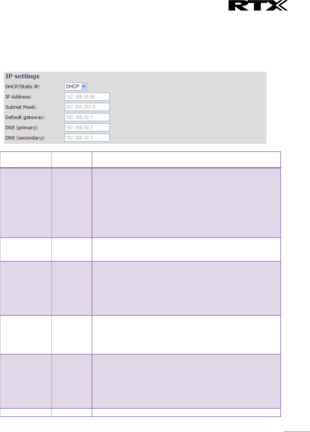
SME VoIP System Guide, Version 2.6
Proprietary and Confidential
Chapter: SME VoIP Administration Interface
40
5.5 Network
In this section, we describe the different parameters available in the network configurations menu.
5.5.1 IP Settings
Screenshot
Parameter
Default
Values
Description
DHCP/Static IP
DHCP
If DHCP is enabled, the device automatically obtains TCP/IP
parameters.
Possible value(s): Static, DHCP
DHCP: IP addresses are allocated automatically from a pool of leased
address.
Static IP: IP addresses are manually assigned by the network
administrator.
If the user chooses DHCP option, the other IP settings or options are
not available.
IP Address
NA
32-bit IP address of device (e.g. base station). 64-bit IP address will be
supported in the future.
Permitted value(s): AAA.BBB.CCC.DDD
Subnet Mask
NA
Is device subnet mask.
Permitted value(s): AAA.BBB.CCC.DDD
This is a 32-bit combination used to describe which portion an IP
address refers to the subnet and which part refers to the host.
A network mask helps users know which portion of the address
identifies the network and which portion of the address identifies the
node.
Default Gateway
NA
Device’s default network router/gateway (32-bit).
Permitted value(s): AAA.BBB.CCC.DDD e.g. 192.168.50.0
IP address of network router that acts as entrance to other network.
This device provides a default route for TCP/IP hosts to use when
communicating with other hosts on hosts networks.
DNS (Primary)
NA
Main server to which a device directs Domain Name System (DNS)
queries.
Permitted value(s): AAA.BBB.CCC.DDD or <URL>
This is the IP address of server that contains mappings of DNS domain
names to various data, e.g. IP address, etc.
The user needs to specify this option when static IP address option is
chosen.
DNS (Secondary)
NA
This is an alternate DNS server.
SME VoIP System Guide, Version 2.6
Proprietary and Confidential
Chapter: SME VoIP Administration Interface
41
5.5.2 VLAN Settings
Enable users to define devices (e.g. Base station, etc.) with different physical connection to communicate as
if they are connected on a single network segment.
The VLAN settings can be used on a managed network with separate Virtual LANs (VLANs) for sending voice
and data traffic. To work on these networks, the base stations can tag voice traffic it generates on a specific
“voice VLAN” using the IEEE 802.1q specification.
Screenshot
Parameter
Default Values
Description
VLAN id
0
Is a 12 bit identification of the 802.1Q VLAN.
Permitted value(s): 0 to 4094 (only decimal values are accepted)
A VLAN ID of 0 is used to identify priority frames and ID of 4095 (i.e.
FFF) is reserved.
Null means no VLAN tagging or No VLAN discovery through DHCP.
VLAN User
Priority
0
This is a 3 bit value that defines the user priority.
Values are from 0 (best effort) to 7 (highest); 1 represents the lowest
priority. These values can be used to prioritize different classes of
traffic (voice, video, data, etc).
Permitted value(s): 8 priority levels (i.e. 0 to 7)
VLAN
Synchronization
Disabled
Default disabled. By enabled the VLAN ID is automatic synchronised
between the bases in the chain. Bases will be automatic rebooted
during the synchronization.
For further help on VLAN configuration refer to Appendix.
5.5.3 DHCP Options
Screenshot
Parameter
Default Values
Description
Plug-n-Play
Disabled
Enabled: DHCP option 66 to automatically provide PBX IP address to
base.
SME VoIP System Guide, Version 2.6
Proprietary and Confidential
Chapter: SME VoIP Administration Interface
42
5.5.4 NAT Settings
We define some options available when NAT aware routers are enabled in the network.
Screenshot
Parameter
Default Values
Description
Enable STUN
Disabled
Enable to use STUN
STUN Server
NA
Permitted value(s): AAA.BBB.CCC.DDD (Currently only Ipv4 are
supported) or url (e.g.: firmware.rtx.net).
STUN Bindtime
Determine
Enabled
STUN Bindtime
Guard
80
Permitted values: Positive integer default is 90, unit is in seconds
Enable RPORT
Disabled
Enable to use RPORT in SIP messages.
Keep alive time
90
This defines the frequency of how keep-alive are sent to maintain
NAT bindings.
Permitted values: Positive integer default is 90, unit is in seconds
5.5.5 SIP/RTP Settings
These are some definitions of SIP/RTP settings:
Screenshot
Parameter
Default Values
Description
Use Different
SIP Ports
Disabled
If disabled, the Local SIP port parameter specifies the source port
used for SIP signalling in the system.
If enabled, the Local SIP Port parameter specifies the source port
used for first user agent (UA) instance. Succeeding UA’s will get
succeeding ports.

SME VoIP System Guide, Version 2.6
Proprietary and Confidential
Chapter: SME VoIP Administration Interface
43
RTP
Collision
Detection
Enabled
Enable: If two sources with same SSRC, the following RTX is discarded.
Disabled: No check – device will accept all sources.
Local SIP
port
5060
The source port used for SIP signalling
Permitted values: Port number default 5060.
SIP ToS/QoS
0x68
Priority of call control signalling traffic based on both IP Layers of
Type of Service (ToS) byte. ToS is referred to as Quality of Service
(QoS) in packet based networks.
Permitted values: Positive integer, default is 0x68
RTP port
50004
The first RTP port to use for RTP audio streaming.
Permitted values: Port number default 50004 (depending on the
setup).
RTP port
range
40
The number of ports that can be used for RTP audio streaming.
Permitted values: Positive integers, default is 40
RTP
TOS/QoS
0xB8
Priority of RTP traffic based on the IP layer ToS (Type of Service) byte.
ToS is referred to as Quality of Service (QoS) in packet based
networks.
See RFC 1349 for details. “cost bit” is not supported.
o Bit 7..5 defines precedence.
o Bit 4..2 defines Type of Service.
o Bit 1..0 are ignored.
Setting all three of bit 4..2 will be ignored.
Permitted values: Positive integer, default is 0xB8
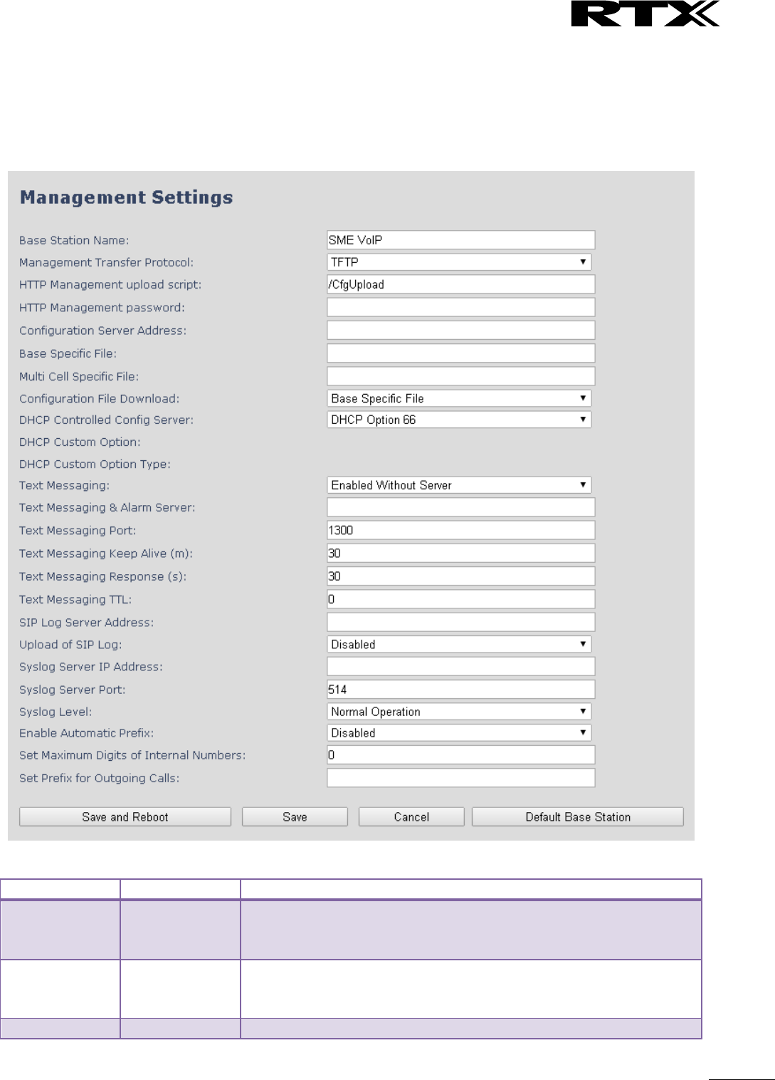
SME VoIP System Guide, Version 2.6
Proprietary and Confidential
Chapter: SME VoIP Administration Interface
44
5.6 Management Settings Definitions
The administrator can configure base stations to perform some specific functions such as configuration of
file transfers, firmware up/downgrades, password management, and SIP/debug logs.
Screenshot
Parameter
Default value
Description
Base Station
Name:
SME VoIP
It indicates the title that appears at the top window of the browser
and is used in the multicell page.
Maximum characters: 35
Management
Transfer
Protocol
TFTP
The protocol assigned for configuration file and central directory
Valid Input(s): TFTP, HTTP, HTTPs
HTTP
Empty
The folder location or directory path that contains the configuration

SME VoIP System Guide, Version 2.6
Proprietary and Confidential
Chapter: SME VoIP Administration Interface
45
Management
upload script
files of the Configuration server. The configuration upload script is a
file located in e.g. TFTP server or Apache Server which is also the
configuration server.
Permitted value(s): /<configuration-file-directory>
Example: /CfgUpload
Note: Must begin with (/) slash character. Either / or \ can be used.
HTTP
Management
password
Empty
Password that should be entered in order to have access to the
configuration server.
HTTP client credentials are formed by “User name” and the “HTTP
Management password”.
Permitted value(s): 8-bit string length
Configuration
server
address
Empty
Server/device that provides configuration file to base station.
Type: DNS or IP address
Permitted value(s): AAA.BBB.CCC.DDD or <URL>
Base Specific
File
Empty
Base configuration file
Multi Cell
Specific File
Empty
The file name must be the chain id of the system.
E.g 00087b0a00b3.cfg
Permitted value(s): Format of file is chain ID.cfg
Configuration
File Download
Disabled
Base Specific file: Used when configuring a single cell base
Multicell Specific File: Used when configuring a multicell based
system
Base and Multicell Specific File: Used on out of factory bases to
specify VLAN and Multicell ID and settings.
DHCP
Controlled
Config Server
Disabled
Provisioning server options.
DHCP Option 66: Look for provision file by TFTP boot up server.
DHCP Custom Option: Look for provision file by custom option
DHCP Custom Option & Option 66: Look for provision file by first
custom option and then option 66.
DHCP Custom
Option
Empty
By default option 160, but custom option can be defined.
An option 160 URL defines the protocol and path information by
using a fully qualified domain name for clients that can use DNS.
DHCP Custom
Option Type
Empty
URL: URL of server with path.
Example of URL: http://myconfigs.com:5060/configs
Default configuration file on server must follow the name: MAC.cfg
IP Address: IP of server with path.
Text
Messaging
Disabled
Disable/enable messaging with Mobicall server
The third option is to “Enable Without Server”. With this setting
handset can send messages to other handsets, which support
messaging.
Note: Contact Mobicall to get the proper version and setup for
Mobicall server
Text
Messaging &
Alarm server
Empty
Permitted value(s): AAA.BBB.CCC.DDD or <URL>
Text
Messaging
Port
1300
Port number of message server.
Text
Messaging
Keep Alive
30
This defines the frequency of how keep-alive are sent
Permitted values: Positive integer, unit is in minutes

SME VoIP System Guide, Version 2.6
Proprietary and Confidential
Chapter: SME VoIP Administration Interface
46
(m)
Text
Messaging
Response (s)
30
This defines the frequency of how response timeout
Permitted values: Positive integer, unit is in seconds
Text
Messaging
TTL
0
This defines the text messaging time to live
Permitted values: Positive integer, unit is in seconds
SIP Log Server
Address
Empty
Permitted value(s): AAA.BBB.CCC.DDD or <URL>
Requires a predefined folder named: \SIP
Upload of SIP
Log
Disabled
Enable this option to save low level SIP debug messages to the server.
The SIP logs are saved in the file format:
<MAC_Address><Time_Stamp>SIP.log
Syslog Server
IP-Address
Empty
Permitted value(s): AAA.BBB.CCC.DDD or <URL>
Syslog Server
Port
Empty
Port number of syslog server.
Syslog Level
Off
Off: No data is saved on syslog server
Normal Operation: Normal operation events are logged, incoming
call, outgoing calls, handset registration, DECT location, and call lost
due to busy, critical system errors, general system information.
System Analyze: Handset roaming, handset firmware updates status.
The system 46nalyse level also contains the messages from normal
operation.
Debug: Used by RTX for debug. Should not be enabled during normal
operation.
Enable
Automatic
Prefix
Disabled
Disabled: Feature off.
Enabled: The base will add the leading digit defined in “Set Prefix for
Outgoing Calls”.
Enabled + fall through on * and #: Will enable detection of * or # at
the first digit of a dialled number. In case of detection the base will
not complete the dialled number with a leading 0.
Examples:
1: dialed number on handset * 1234 - > dialed number to the pabx
*1234
2: dialed number on handset #1234 - > dialed number to the pabx
#1234
3: dialed number on handset 1234 - > dialed number to the pabx
01234
Set Maximum
Digits of
Internal
Numbers
0
Used to detect internal numbers. In case of internal numbers no
prefix number will be added to the dialled number.
Set Prefix for
Outgoing Calls
Empty
Prefix number for the enabled automatic prefix feature.
Permitted value(s): 1 to 9999
There are three ways of configuring the system.
1. Manual configuration by use of the Web server in the base station(s)
2. By use of configuration files that are uploaded from a disk via the “Configuration” page on the Web
server.
3. By use of configuration files which the base station(s) download(s) from a configuration server.
For further details refer to doc reference [3].

SME VoIP System Guide, Version 2.6
Proprietary and Confidential
Chapter: SME VoIP Administration Interface
47
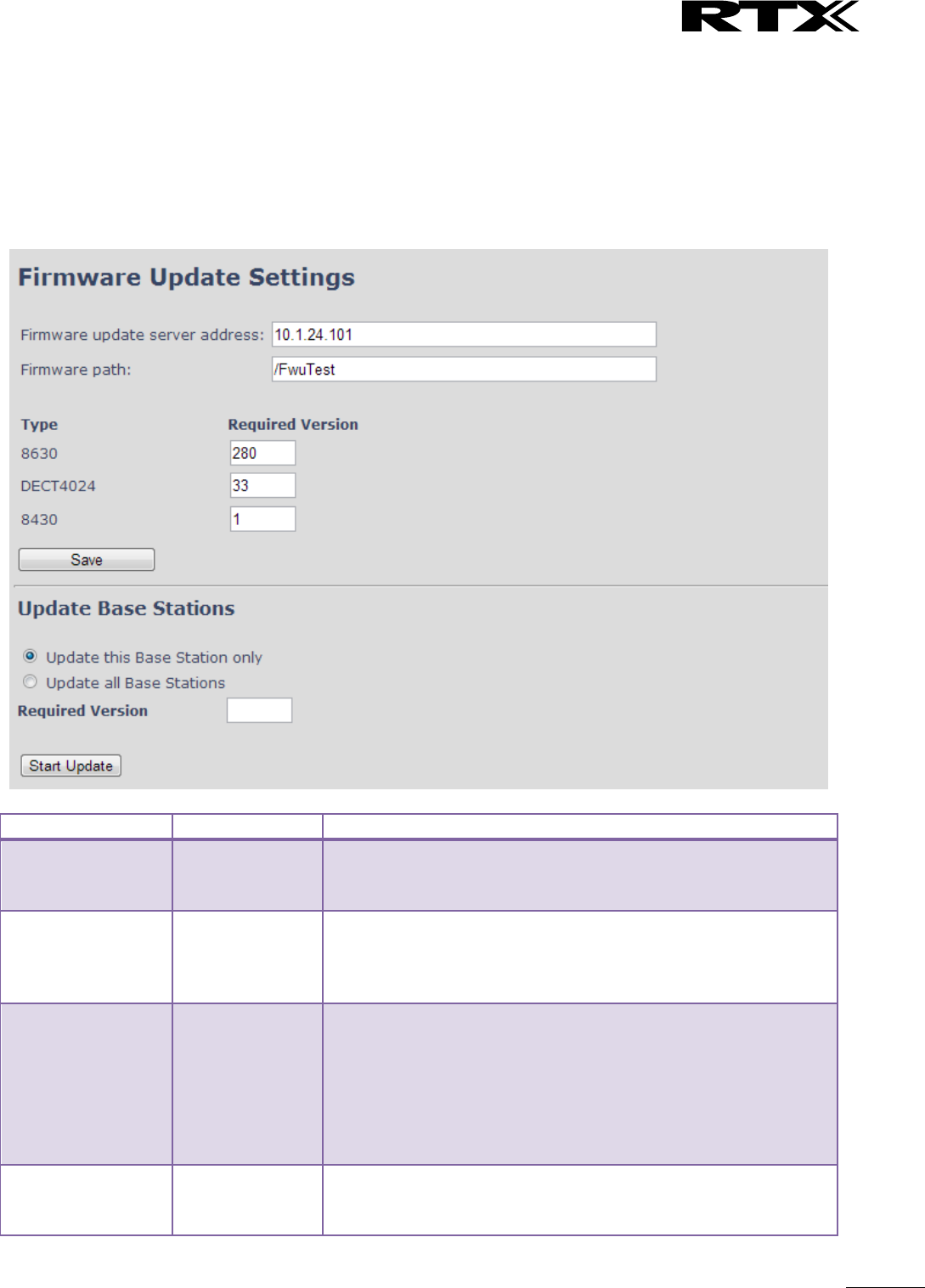
SME VoIP System Guide, Version 2.6
Proprietary and Confidential
Chapter: SME VoIP Administration Interface
48
5.7 Firmware Update Definitions
In this page, the system administrator can configure how base stations and SIP nodes upgrade/downgrade
to the relevant firmware. Handset firmware update status can be found in the extensions page and
repeater firmware update status in the repeater page. Base firmware update status is found in the multicell
page.
Screenshot
Parameter
Default Value(s)
Description
Firmware update
server address
Empty
IP address or DNS of firmware update files source
Valid Inputs: AAA.BBB.CCC.DDD or <URL>
Example: firmware.rtx.net or 10.10.104.41
Firmware path
Empty
Location of firmware on server (or firmware update server path
where firmware update files are located).
Example: /East_Fwu
Note: Must begin with (/) slash character
Required Version
Type
Empty
Version of firmware to be upgraded (or downgraded) on
handset type or repeater.
Valid Input(s): 8-bit string length. E.g. 280
Note: Value version 0 will disable firmware upgrade for
handsets and/or repeater
Note: Two handset types will be serial firmware upgraded. First
type 8630 then type 8430.
Required Version
base
Empty
Version of firmware to be upgraded (or downgraded) on Base
station. Base units are referred to as gateways over here.
Valid Input(s): 8-bit string length. E.g. 280
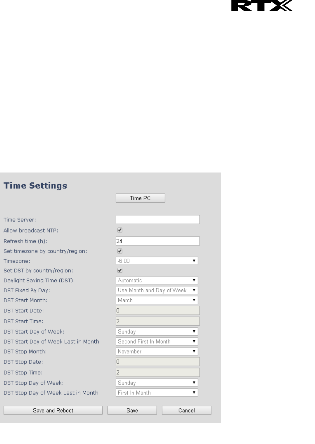
SME VoIP System Guide, Version 2.6
Proprietary and Confidential
Chapter: SME VoIP Administration Interface
49
5.8 Time Server
In this section, we describe the different parameters available in the Time Server menu.
The Time server supplies the time used for data synchronisation in a multi-cell configuration. As such it is
mandatory for a multi-cell configuration. The system will not work without a time server configured.
As well the time server is used in the debug logs and for SIP traces information pages, and used to
determine when to check for new configuration and firmware files.
NOTE: It is not necessary to set the time server for standalone base stations (optional).
Press the “Time PC” button to grab the current PC time and use in the time server fields.
NOTE:
When time server parameters are modified/changed synchronisation between base stations can take up to
15 minutes before all base stations are synchronised, depending on the number of base stations in the
system. Changing time settings will require a reboot of system.
Screenshot

SME VoIP System Guide, Version 2.6
Proprietary and Confidential
Chapter: SME VoIP Administration Interface
50
Parameter
Default Values
Description
Time Server
Empty
DNS name or IP address of NTP server.
Enter the IP/DNS address of the server that distributes
reference clock information to its clients including Base
stations, Handsets, etc.
Valid Input(s): AAA.BBB.CCC.DDD or URL (e.g. time.server.com)
Currently only Ipv4 address (32-bit) nomenclature is supported.
Allow broadcast
NTP
Checked
By checked time server is used.
Refresh time (h)
Empty
The window time in hours within which time server refreshes.
Valid Inputs: positive integer
Set timezone by
country/region
Checked
By checked country setting is used (refer to country web page).
Time Zone
0
Refers to local time in GMT or UTC format.
Min: -12:00
Max: +13:00
Set DST by
country/region
Checked
By checked country setting is used (refer to country web page).
Daylight Saving
Time (DST)
Disabled
The system administrator can Enable or Disable DST manually.
Automatic: Enter the start and stop dates if you select
Automatic.
DST Fixed By Day
Use Month and
Date
You determine when DST actually changes. Choose the
relevant date or day of the week, etc. from the drop down
menu.
DST Start Month
March
Month that DST begins
Valid Input(s): Gregorian months (e.g. January, February, etc.)
DST Start Date
25
Numerical day of month DST comes to effect when DST is fixed
to a specific date
Valid Inputs: positive integer
DST Start Time
3
DST start time in the day
Valid Inputs: positive integer
DST Start Day of
Week
Monday
Day within the week DST begins
DST Start Day of
Week, Last in Month
Last in Month
Specify the week that DST will actually start.
DST Stop Month
October
The month that DST actually stops.
DST Stop Date
1
The numerical day of month that DST turns off.
Valid Inputs: positive integer (1 to 12)
DST Stop Time
2
The time of day DST stops
Valid Inputs: positive integer (1 to 12)
DST Stop Day of
Week
Sunday
The day of week DST stops
DST Stop Day of
Week Last in Month
First in Month
The week within the month that DST will turn off.
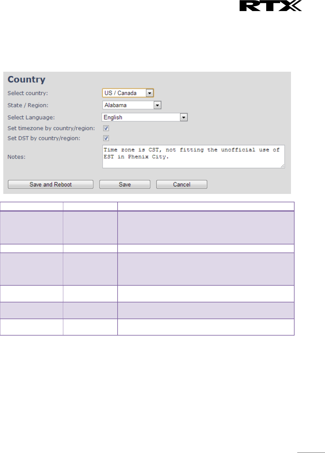
SME VoIP System Guide, Version 2.6
Proprietary and Confidential
Chapter: SME VoIP Administration Interface
51
5.9 Country
The country setting controls the in-band tones used by the system. To select web interface language go to
the management page.
Screenshot
Parameter
Default Values
Description
Select Country
Germany
Supported countries: Australia, Belgium, Brasil, Denmark,
Germany, Spain, France, Ireland, Italia, Luxembourg,
Nederland, New Zealand, Norway, Portugal, Swiss, Finland,
Sweden, Tyrkey, United Kingdom, US/Canade, Austria
State / Region
NA
Only shown by country selection US/Canada, Autralia, Brasil
Select Language
English
Web interface language. Number of available languages:
English, Dansk, Italiano, Tyrkie, Deutsch, Portuguese, Hrvatski,
Srpski, Slovenian, Nederlands, Francaise, Espanol, Russian,
Polski.
Set timezone by
country/region
checked
When checked timezone will follow country/region
Set DST by
country/region
checked
When checked DST will follow country/region
Notes
Empty
Only showing notes to time setting for countries: US/Canada,
Brasil
NOTE: By checked timezone and DST the parameters in web page Time will be discarded.
The following types of in-band tones are supported:
- Dial tone
- Busy tone
- Ring Back tone
- Call Waiting tone
- Re-order tone
SME VoIP System Guide, Version 2.6
Proprietary and Confidential
Chapter: SME VoIP Administration Interface
52
5.10 Security
The security section is used for loading of certificates and for selecting if only trusted certificates are used.
Furthermore, web password can be configured.
The Security web is divided into three sections: Certificates (trusted), SIP Client Certificates (and keys) and
Password administration.
To setup secure fwu and configuration file download select HTTPs for the Management Transfer Protocol
(refer to management web).
SIP and RTP security is server dependent and in order to configure user must use the web option Servers
(refer to servers web).
5.10.1 Certificates
The certificates list contains the list of loaded certificates for the system. Using the left column check mark
it is possible to check and delete certificates. To import a new certificate use the mouse “select file” and
browse to the selected file. When file is selected, use the “Load” bottom to load the certificate.
The certificate format supported is DER encoded binary X.509 (.cer).
Screenshot
Certificates list
Parameter
Default Values
Description
Idx
Fixed indexes
Index number
Issued To
Empty
IP address – which is part of the certificate file
Issued To
Empty
Organisation, Company – which is part of the certificate file
Valid Until
Empty
Date Time Year – which is part of the certificate file
Screenshot
By enabling Use Only Trusted Certificates, the certificates the base will receive from the server must be
valid and loaded into the system. If no valid matching certificate is found during the TLS connection
establishment, the connection will fail. When Use Only Trusted Certificates is disabled, all certificates
received from the server will be accepted.
sNote: It is important to use correct date and time of the system when using trusted certificates. In case of
time/date not defined the certificate validation can fail.
SME VoIP System Guide, Version 2.6
Proprietary and Confidential
Chapter: SME VoIP Administration Interface
53
5.10.2 SIP Client Certificates
To be able to establish a TLS connection in scenarios, where the server requests a client certificate, a
certificate/key pair must be loaded into the base. This is currently supported only for SIP.
To load a client certificate/key pair, both files must be selected at the same time, and it is done by pressing
“select files” under “Import SIP Client Certificate and Key Pair” and then select the certificate file as well as
the key file at the same time. Afterwards, press load.
The certificate must be provided as a DER encoded binary X.509 (.cer) file, and the key must be provided as
a binary PKCS#8 file.
Note: Use Chrome for loading SIP Client Certificates
Screenshot
5.10.3 Password
In the below the password parameters are defined.
Screenshot
Parameter
Default Values
Description
Username
Admin
Can be modified to any supported character and number
Maximum characters: 15
Current Password
Admin
Can be modified to any supported character and number
New Password
Empty
Change to new password
Maximum characters: 15
Confirm Password
Empty
Confirm password to reduce accidently wrong changes of
passwords
Password valid special signs: @/|<>-_:.!?*+#
Password valid numbers: 0-9
Password valid letters: a-z and A-Z
SME VoIP System Guide, Version 2.6
Proprietary and Confidential
Chapter: SME VoIP Administration Interface
54
5.11 Central Directory and LDAP
The SME VOIP system support two types of central directories, a local central directory or LDAP directory.
For both directories caller id look up is made with match for 6 digits of the phone number.
5.11.1 Local Central Directory
Select local and save for local central directory.
Screenshot
Parameter
Default Values
Description
Local
Local
Drop down menu to select between local central directory and
LDAP based central directory
Server
Empty
The parameter is used if directory file is located on server.
Valid Inputs: AAA.BBB.CCC.DDD or <URL>
Refer to appendix for further details.
Filename
Empty
The parameter is used if directory file is located on server.
Refer to appendix for further details
Phonebook reload
interval (s)
0
The parameter is controlling the reload interface of phonebook
in seconds. The feature is for automatic reload the base
phonebook file from the server with intervals. It is
recommended to specify a conservative value to avoid
overload of the base station.
With default value setting 0 the reload feature is disabled.
5.11.1.1 Import Central Directory
The import central directory feature is using a browse file approach. After file selection press the load
button to load the file. The system support only the original *.csv format. Please note that some excel csv
SME VoIP System Guide, Version 2.6
Proprietary and Confidential
Chapter: SME VoIP Administration Interface
55
formats are not the original csv format. The central directory feature can handle up to 3000 contacts. For
further details of the central directory feature refer to appendix.
5.11.2 LDAP
Select LDAP Server and save for LDAP server configuration.
Screenshot
Screenshot
Parameter
Default Values
Description
LDAP Server
LDAP Server
Drop down menu to select between local central directory and
LDAP based central directory. LDAP Server is displayed when
LDAP server is selected.
Server
Empty
IP address of the LDAP server.
Valid Inputs: AAA.BBB.CCC.DDD or <URL>
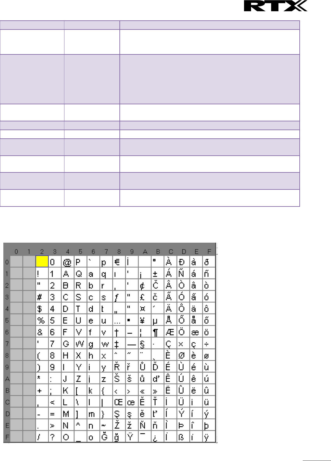
SME VoIP System Guide, Version 2.6
Proprietary and Confidential
Chapter: SME VoIP Administration Interface
56
Port
Empty
The server port number that is open for LDAP connections.
Sbase
Empty
Search Base. The criteria depends on the configuration of the
LDAP server. Example of the setting is CN=Users, DC=umber,
DC=loc
LDAP filter
Empty
LDAP Filter is used to as a search filter, e.g. setting LDAP filter
to (|(givenName=%*)(sn=%*)) the IP-DECT will use this filter
when requesting entries from the LDAP server. % will be
replaced with the entered prefix e.g searching on J will give the
filter (|(givenName=J*)(sn=J*)) resulting in a search for given
name starting with a J or surname starting with J.
Bind
Empty
Bind is the username that will be used when the IP-DECT phone
connects to the server
Password
Empty
Password is the password for the LDAP Server
Virtuel Lists
Disabled
By enable, virtual list searching is possible
Name
Empty
The name can be used to specify if sn+givenName or cn
(common name) is return in the LDAP search results
Work Number
Empty
Work number is used to specify that LDAP attribute that will be
mapped to the handset work number
Home Number
Empty
Home number is used to specify that LDAP attribute that will be
mapped to the handset home number
Mobile Number
Empty
Mobile number is used to specify that LDAP attribute that will
be mapped to the handset mobile number
5.11.3 Characters supported
The below table shows which characters are supported in the communication between RTX8663 and
handset.

SME VoIP System Guide, Version 2.6
Proprietary and Confidential
Chapter: SME VoIP Administration Interface
57
5.12 Multi-cell Parameter Definitions
In this section, we describe the different parameters available in the Multi-cell configurations menu.
5.12.1 Settings for Base Unit
Description of Settings for Specific Base units is as follows:
Screenshot
Multicell status covers status of data synchronization. The status “Keep-alive” means normal operation.
Parameter
Default values
Description
Multi cell
system
Disabled
Enable this option to allow the Base unit to be set in multi-cell mode
(can be set either as master or slave in the multi-cell chain system –
refer to MAC-units in Chain section for details).
Valid Inputs: Enable, Disable
Must “save and reboot” after change from disabled to enable.
System chain ID
Empty
This is an identifier (in string format e.g. 2275) that is unique for a
specific multi-cell system.
The Chain ID value MUST not be equal to a used SIP account. The Chain
ID use up a SIP account with this value.
Note: Chain ID is used as SIP account for check Sync. Default value is
512, which means extension 512 must not be used – unless the chain
ID is modified. Chain ID can be modified by provisioning only.
Note: There can be several multi-cell systems in SME network. Up to 24
levels of base stations chains are permitted in a setup.
Valid Input: The Web site allow max 5 digits in this field.
Synchronization
time (s)
60 sec
This specifies the period in seconds when elements/nodes (e.g. Base
units) in a specific Multi-cell will synchronise to each other.
SME VoIP System Guide, Version 2.6
Proprietary and Confidential
Chapter: SME VoIP Administration Interface
58
If no keep-alive packets are received within a period of
2*NETWORK_SYNC_TIME, the base will be indicated as lost in the
multi cell configuration. The parameter is also used with “Auto create
multi primary” feature.
Data Sync:
Multicast
To select between multicast or Peer to Peer data synchronisation
mode.
The multicast port range and IP addresses used is calculated from the
chain id.
The multicast feature uses the port range: 49200 – 49999
The multicast feature IP range: 224.1.0.0 – 225.1.0.0
Multicast uses UDP.
Primary Data
Sync IP
Empty
IP of base station data sync source – the base handling the data
synchronisation.
Using multicast this base IP is selected automatically.
The data sync feature uses the port range: 49200 – 49999
NOTE: Using Peer to Peer mode the IP of the base used for data sync.
source MUST be defined.
NOTE: Using Peer to Peer mode with version below V306 limits the
system automatic recovery feature – as there is no automatic recovery
of the data sync. source in Peer to Peer mode.
Multi cell
debug
None
Enable this feature, if you want the system to catalogue low level multi-
cell debug information or traces.
Options:
Data Sync: Writes header information for all packets received and sent
to be used to debug any special issues. Generates LOTS of SysLog
signaling and is only recommended to enable shortly when debugging.
Auto Tree: Writes states and data related to the Auto Tree
Configuration feature.
Both: Both Data Sync and Auto Tree are enabled.
NOTE: Must only be used for debug purpose and not enabled on a
normal running system
5.12.2 DECT System Settings
Description of DECT Settings for Specific Base units is as follows:
Screenshot
Parameter
Default values
Description
DECT system
RFPI
Not able
This is a radio network identity accessed by all Base units in a specific
multi-cell system. It composed of 5 octets. It is actually 5 different
variables combined together.
RFPI Format: XX XX XX XX XX (where XX are HEX values)
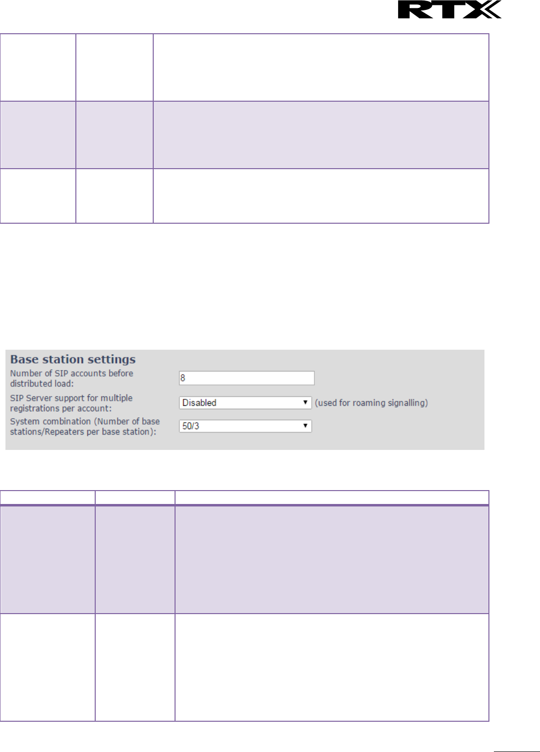
SME VoIP System Guide, Version 2.6
Proprietary and Confidential
Chapter: SME VoIP Administration Interface
59
Allow multi
primary:
Disabled
This feature is used for multi-location setups. Allows two or more
primary in the same system.
The two cells will be unsynchronized and handover will not be possible.
“Auto Configure DECT sync source tree” must be enabled for this feature
to also be enabled
Auto create
multi
primary:
Disabled
By enabled the system can generate cells in case a base goes into faulty
mode. Two cells will only be generated in case no radio connection
between the two cells is present. In order to recover the full system after
establish of the faulty base, the system must be rebooted.
Allow multi primary must be enabled for this feature to also be enabled.
Auto
configure
DECT sync
source tree
Enabled
Enable this to allow the system to automatically synchronise the multi-
cell chain/tree.
NOTE: Must be enabled in order to allow a new primary recover in case
the original primary goes into faulty mode.
Note: To run with a system with two separate primary in two locations “Allow multi primary” and “Auto
configure DECT sync source tree” must be enabled. To add the second primary the slave must manually be
configured as primary. Alternatively the “Auto create multi primary” must be enabled.
5.12.3 Base System Settings
Description of SIP Settings for Specific Base units is as follows:
Screenshot
Parameter
Default Values
Description
Number of SIP
accounts before
distributed load
8
The maximum number of handsets or SIP end nodes that are
permitted to perform location registration on a specific Base unit
before load is distributed to other base units. The parameter can be
used to optimize the handset distribution among visible
basestations.
Note: A maximum of 8 simultaneous calls can be routed through
each Base unit in a multi-cell setup.
Permitted Input: Positive Integers (e.g. 6)
SIP Server support
for multiple
registrations per
account
Disabled
Disable this option so it is possible to use same extension (i.e. SIP
Account) on multiple phones (SIP end nodes). These phones will ring
simultaneously for all incoming calls. When a phone (from a SIP
account group) initiates a handover from Base X to Base Y, this
phone will de-register from Base X, and register to Base Y after a
call.
Permitted Input:
Disabled: No SIP de-registration will be made when a handset

SME VoIP System Guide, Version 2.6
Proprietary and Confidential
Chapter: SME VoIP Administration Interface
60
roams to another base station
Enabled: The old SIP registration will be deleted with a SIP
Deregistration, when a handset roams to another base
station
System
combination
(Number of base
stations/Repeaters
per base station):
50/3
Select between basic base configurations.
50/3 : 50 bases and 3 repeaters
127/1 : 127 bases and 1 repeater
254/0 : 254 bases and 0 repeater
The configuration cannot be modified after a system is established.
The configuration must be set during first multicell configuration.
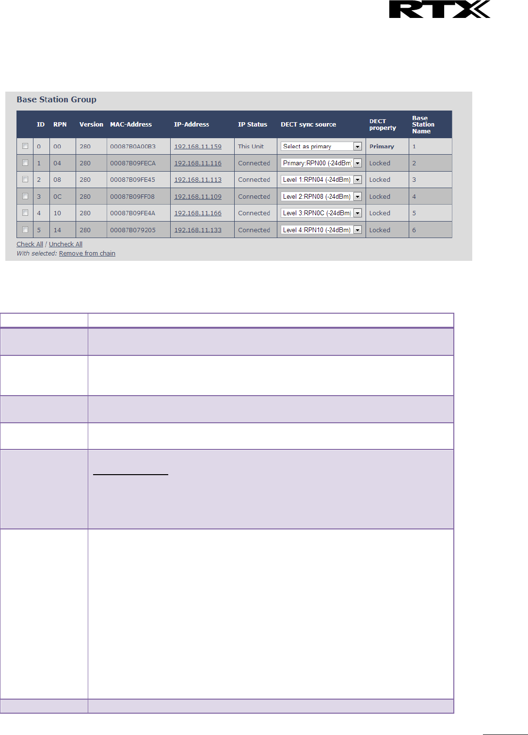
SME VoIP System Guide, Version 2.6
Proprietary and Confidential
Chapter: SME VoIP Administration Interface
61
5.12.4 Base Station Group
The Base station group list various parameter settings for base stations including chain level information.
Screenshot:
Parameters
Description
ID
Base unit identity in the chained network.
Permitted Output: Positive Integers
RPN
The Radio Fixed Part Number is an 8-bit DECT cell identity allocated by the
installer. The allocated RPN within the SME must be geographically unique.
Permitted Output: 0 to 255 (DEC) OR 0x00 to 0xFF (HEX)
Version
Base station current firmware version.
Permitted Output: positive Integers with dot (e.g. 273.1)
MAC Address
Contains the hardware Ethernet MAC address of the base station. It varies from
Base station to Base stations.
IP Status
Current Base station behaviour in the SME network.
Possible Outputs
Connected: The relevant Base station(s) is online in the network
Connection Loss: Base station unexpectedly lost connection to network
This Unit: Current Base station whose http Web Interface is currently being
accessed
DECT Sync
source
With setting “Auto configure DECT sync source tree” set to Enable, this three will
automatically be generated. If manual configured the administrator should
choose the relevant “multi cell chain” level its wants a specific Base unit be
placed. Maximum number of “multi-cell chain” levels is 12.
Format of the selection: “AAAAAxx: RPNyy (-zz dBm)”
AAAAA: indication of sync. source for the base. Can be “Primary” or “Level xx”
xx: Sync. source base sync. level
yy: Sync. source base RPN
zz: RSSI level of sync. source base seen from the actual base
“(Any) RPN”: When a base is not synchronized to other base. State after reboot of
chain.
Dect Property
Base station characteristics in connection to the current multi cell network.
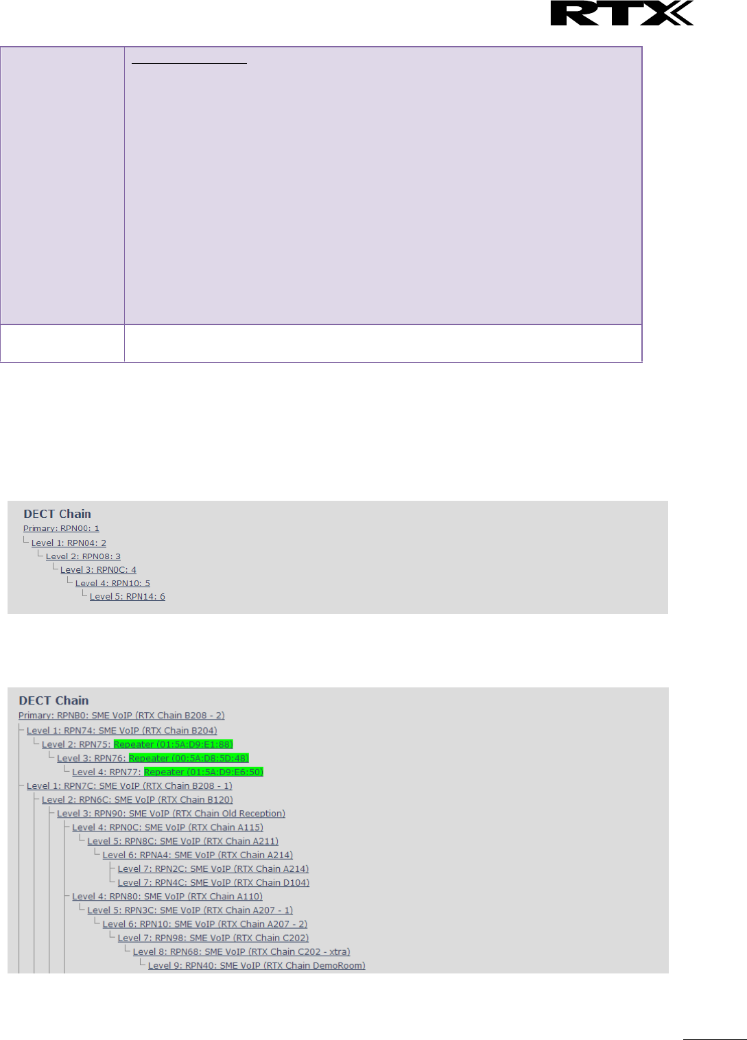
SME VoIP System Guide, Version 2.6
Proprietary and Confidential
Chapter: SME VoIP Administration Interface
62
Possible Output(s)
Primary: Main Base station unto which all other nodes in the chain synchronises
to.
Locked: The Base unit is currently synchronized and locked to the master Base
unit.
Searching: Base unit in the process of locating to a Master/slave as specified in
Dect sync source
Free Running: A locked Base unit that suddenly lost synchronisation to the
Master.
Unknown: No current connection information from specific Base unit
Assisted lock: Base has lost DECT sync. source and Ethernet is used for
synchronization
Sync. Lost: Handset has an active DECT connection with the base. But the base
has lost DECT sync. source connection. The base will stay working as long as the
call is active and will go into searching mode when call is stopped.
Base Station
Name
Name from management settings.
5.12.5 DECT Chain
Below the Base Group Table is the DECT Chain tree. The DECT Chain tree is a graphical presentation of the
Base Group table levels and connections. Repeaters are shown with green highlight.
Screenshot: DECT Chain tree of above configuration
Screenshot: Example of part of DECT Chain tree with repeaters
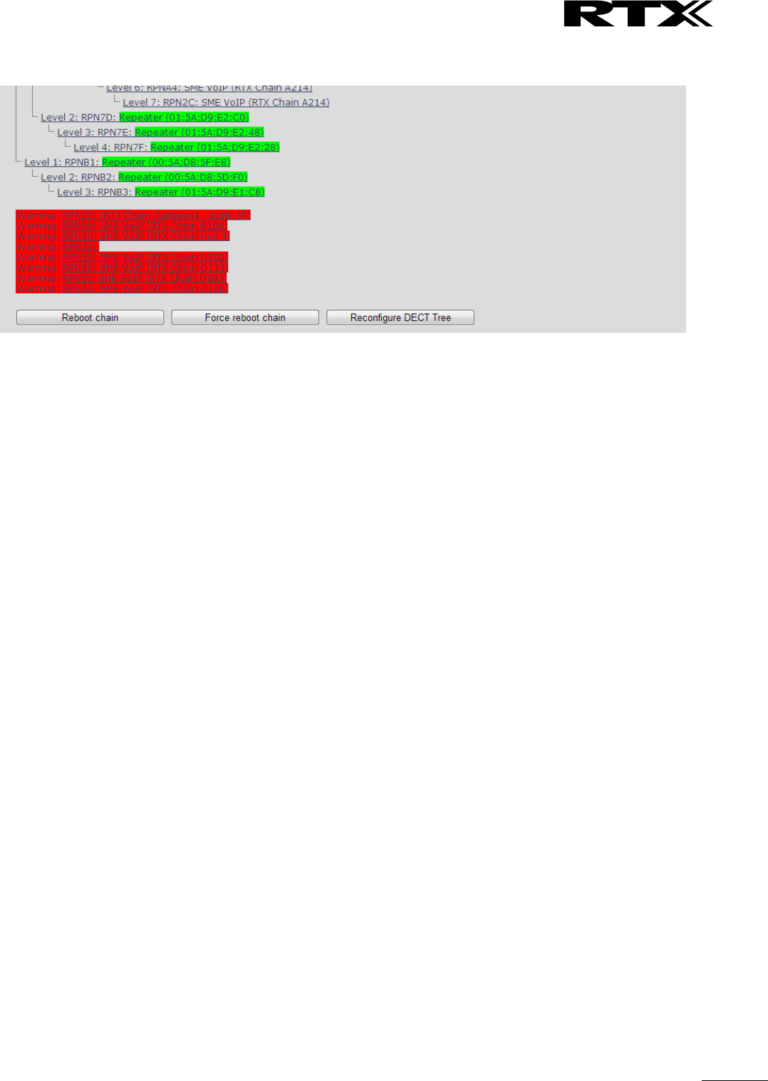
SME VoIP System Guide, Version 2.6
Proprietary and Confidential
Chapter: SME VoIP Administration Interface
63
Screenshot: Example of part of DECT Chain tree with units in Base Group but not in tree by various
reasons.
When a base or repeater has not joined the tree it will be shown with read background below the tree.
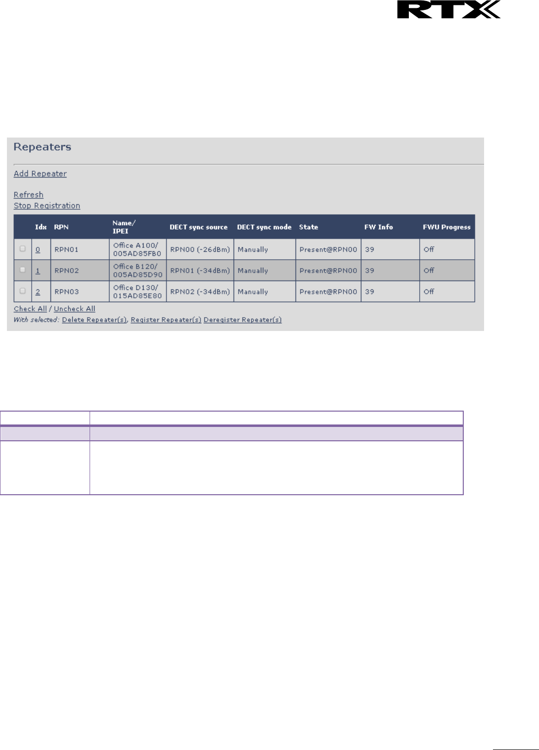
SME VoIP System Guide, Version 2.6
Proprietary and Confidential
Chapter: SME VoIP Administration Interface
64
5.13 Repeaters
Within this section we describe the repeater parameter, and how to operate the repeater.
5.13.1 Add repeater
From repeaters web select “Add Repeater”
Screenshot
Then select “DECT Sync mode”
Screenshot
Parameters
Description
Name
Repeater name. If no name specified the field will be empty
DECT sync mode
Manually: User controlled by manually assign “Repeater RPN” and “DECT sync
source RPN”
Local Automatical: Repeater controlled by auto detects best base signal and auto
assign RPN.
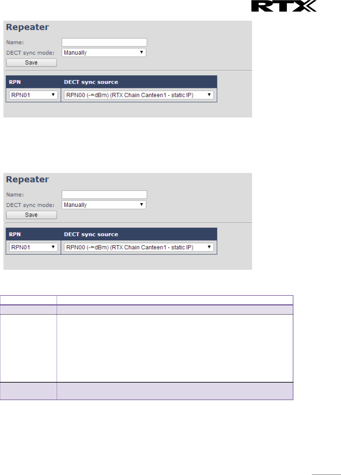
SME VoIP System Guide, Version 2.6
Proprietary and Confidential
Chapter: SME VoIP Administration Interface
65
5.13.1.1 Manually
User controlled by manually assign “Repeater RPN” and “DECT sync source RPN”. The parameters are
selected from the drop down menu.
Screenshot
Parameters
Description
Idx
System counter
RPN
SINGLE CELL SYSTEM:
The base has always RPN00, first repeater will then be RPN01, second repeater
RPN02 and third RPN03 (3 repeaters maximum per base)
MULTI CELL SYSTEM:
Bases are increment by 2^2 in hex, means first base RPN00 second base RPN04
etc., in between RPN01, 02, 03 addressed for repeaters at Primary base and 05,
06, 07 addressed for Secondary base (3 repeaters maximum per base)
DECT sync source
Select the base or repeater the repeater has to be synchronized to.
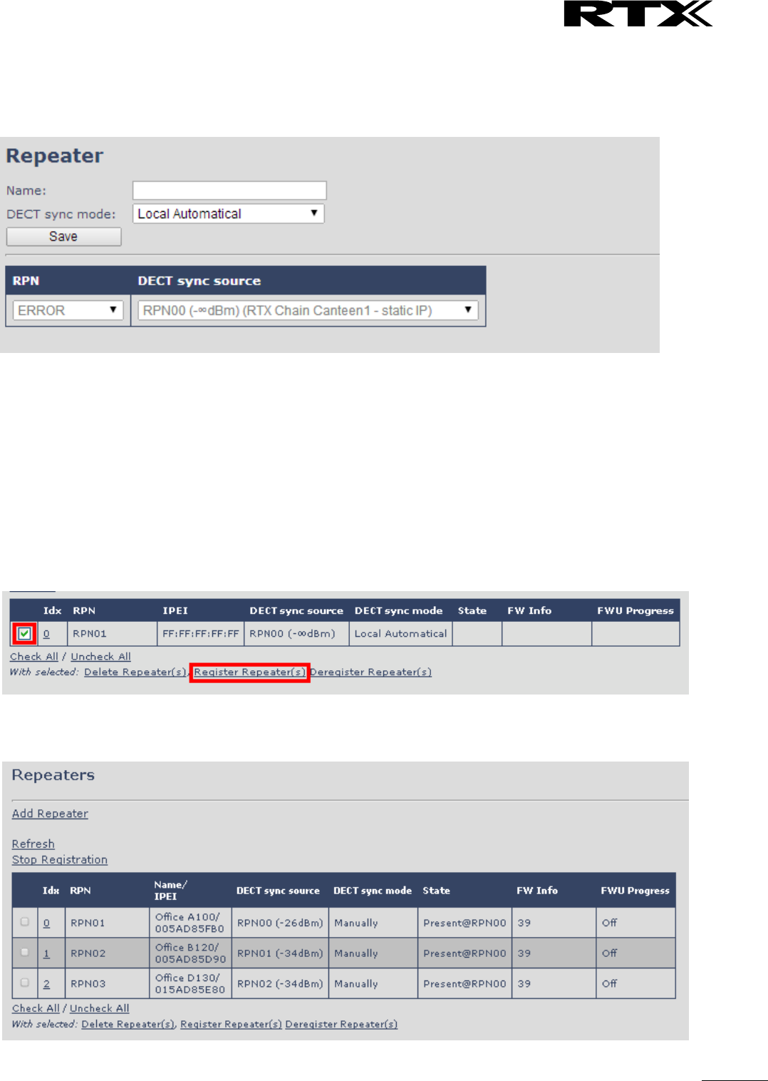
SME VoIP System Guide, Version 2.6
Proprietary and Confidential
Chapter: SME VoIP Administration Interface
66
5.13.1.2 Local Automatical
Repeater controlled by auto detects best base signal and auto assign RPN. The RPN and DECT sync source
are greyed out.
The repeater RPN is dynamic assigned in base RPN range.
With local automatical mode repeater on repeater (chain) is not supported.
5.13.2 Register Repeater
Adding a repeater makes it possible to register the repeater. Registration is made by select the repeater
and pressing register repeater. The base window for repeater registration will be open until the registration
is stopped. By stopping the registration all registration on the system will be stopped inclusive handset
registration.
5.13.3 Repeaters list

SME VoIP System Guide, Version 2.6
Proprietary and Confidential
Chapter: SME VoIP Administration Interface
67
Parameters
Description
IDx
Repeater unit identity in the chained network.
Permitted Output: Positive Integers
RPN
The Radio Fixed Part Number is an 8-bit DECT cell identity allocated by the
installer. The allocated RPN within the SME must be geographically unique.
Permitted Output: 0 to 255 (DEC) OR 0x00 to 0xFF (HEX)
Name/IPEI
Contains the name and the unique DECT serial number of the repeater. If name is
given the field will be empty.
DECT sync
Source
The “multi cell chain” connection to the specific Base/repeater unit. Maximum
number of chain levels is 12.
Sync. source format: “RPNyy (-zz dBm)”
yy: RPN of source
zz: RSSI level seen from the actual repeater
DECT sync Mode
Manually: User controlled by manually assign “Repeater RPN” and “DECT sync
source RPN”
Local Automatical: Repeater controlled by auto detects best base signal and auto
assign RPN.
Chaining Automatical: Base controlled by auto detects best base or repeater
signal and auto assign RPN. This feature will be supported in a future version
State
Present@unit means connected to unit with RPN yy
FW info
Firmware version
FWU Progress
Possible FWU progress states:
Off: Means sw version is specified to 0 = fwu is off
Initializing: Means FWU is starting and progress is 0%.
X% : FWU ongoing
Verifying X%: FWU writing is done and now verifying before swap
”Conn. term. wait” (Repeater): All FWU is complete and is now waiting for
connections to stop before repeater restart.
Complete HS/repeater: FWU complete
Error: Not able to fwu e.g. file not found, file not valid etc
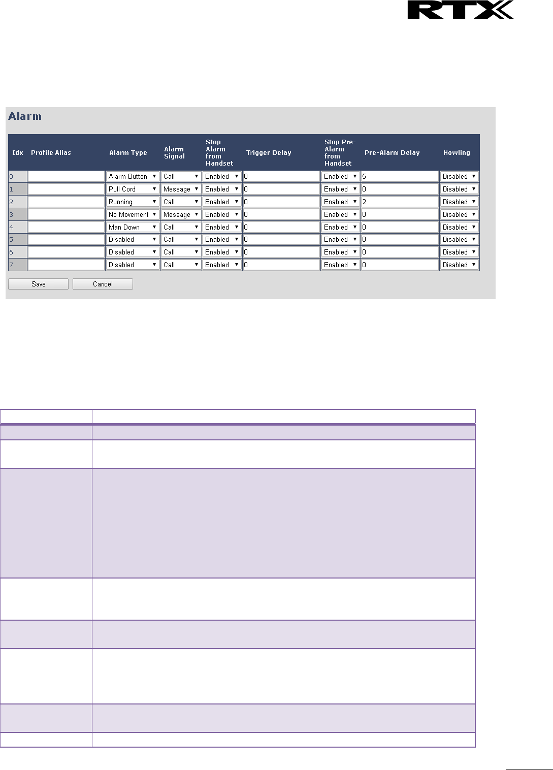
SME VoIP System Guide, Version 2.6
Proprietary and Confidential
Chapter: SME VoIP Administration Interface
68
5.14 Alarm
In the Alarm Settings menu, it is controlled how an alarm appears on the handset. For example if the
handset detects “Man Down”, then it is defined in this menu what alarm signal this type of alarm will send
out and if a pre-alarm shall be signaled etc.
All configuration of the handset Alarm Settings is done from the base station. The concept is that on the
“Alarm” page on the web server, eight different alarm profiles can be configured. Afterwards for each
handset, it can be selected which of the configured alarm profiles, the given handset shall subscribe to.
When this is done the selected alarm profiles are sent to the handset.
See section 5.3.2.3 Multiline: Edit handset
The parameters that can be configured are:
Parameters
Description
Idx
Indicates the index number of a specific alarm.
Profile Alias
An alias or user-friendly name to help identify the different profiles when
selecting which profiles to enable for the individual handsets.
Alarm Type
The type of alarm is dependent of what kind of event that has triggered the alarm
on the handset. The handset supports either of the following categories:
Man Down
No Movement
Running
Pull Cord
Emergency Button
Disabled
Alarm Signal
The way the alarm is signalled as it received on the handset.
Message: A text message to an alarm server.
Call: An outgoing call to the specified emergency number.
Stop Alarm from
Handset
Enable/disable the possibility to stop/cancel the alarm from the handset.
Trigger Delay
The period from when the alarm has fired until the handset shows a pre-alarm
warning. If set to 0, there will be no pre-alarm warning, and the alarm will be
signalled immediately. The alarm algorithm typically needs about 6 sec. to detect
e.g. man down etc.
Stop Pre-Alarm
from Handset
Enable/disable the possibility to stop/cancel the pre-alarm from the handset.
Pre-Alarm Delay
The period from the pre-alarm warning is shown until the actual alarm is

SME VoIP System Guide, Version 2.6
Proprietary and Confidential
Chapter: SME VoIP Administration Interface
69
signalled. The maximum value is 255.
Howling
Enable/disable if howling shall be started in the handset, when the alarm is
signalled. If disabled, only the configured signal is sent (call or message).
This alarm feature is only available on some types of handsets (e.g. the RTX8830)
After configuration, the handset must be rebooted.
5.14.1 Use of Emergency Alarms
As described above, it can be configured if it shall be possible to stop an alarm from the handset. If the
possibility to stop an alarm from the handset is disabled, it is ensured that an alarm is not stopped before
someone at e.g. an emergency center has received the alarm and reacted upon it.
The behavior of a handset when an alarm “is sent” depends on the configured Alarm Signal:
Call: When the Alarm Signal is configured as “Call”, the handset will make a call to the specified
emergency number, and the alarm is considered stopped when the call is terminated. If it is not
allowed to stop the alarm from the handset, it will not be possible to terminate the call from
handset, and the alarm will be considered as stopped only when the remote end (e.g. the
emergency center) terminates the call.
Message: When the Alarm Signal is configured as “Message”, the handset will send an alarm
message to the specified alarm server, and enable auto answer mode. If Howling is enabled, the
handset will also start the Howling tone. The alarm will not stop until a call is made, and since auto
answer mode is enabled, the emergency center can make the call, and the person with the handset
does not have to do anything to answer the call, it will answer automatically. Again, the alarm is
considered stopped, when the call is terminated with the same restrictions as for the Call alarm
signal.
All type of alarms have the same priority. This means that once an alarm is active, it cannot be overruled by
another alarm until the alarm has been stopped. However, if the alarm is not yet active, i.e. if it is in “pre-
alarm” state and an alarm configured with no pre-alarm is fired, then the new alarm will become active and
stop the pending alarm.
Alarms with no pre-alarm are considered important, and there is no possibility to cancel them before they
are sent, and therefore alarms with no pre-alarm, are given higher priority than alarms in pre-alarm state.
The Emergency Button could be an example of an alarm which would be configured without pre-alarm.
Thus, when the Emergency Button is pressed you want to be sure the alarm is sent. However, If another
alarm was already in pre-alarm state, it could potentially be cancelled, and if the Emergency Button alarm
was ignored in this case, no alarm would be sent. This is the reason why alarms with no pre-alarm, are
given higher priority than alarms in pre-alarm state.
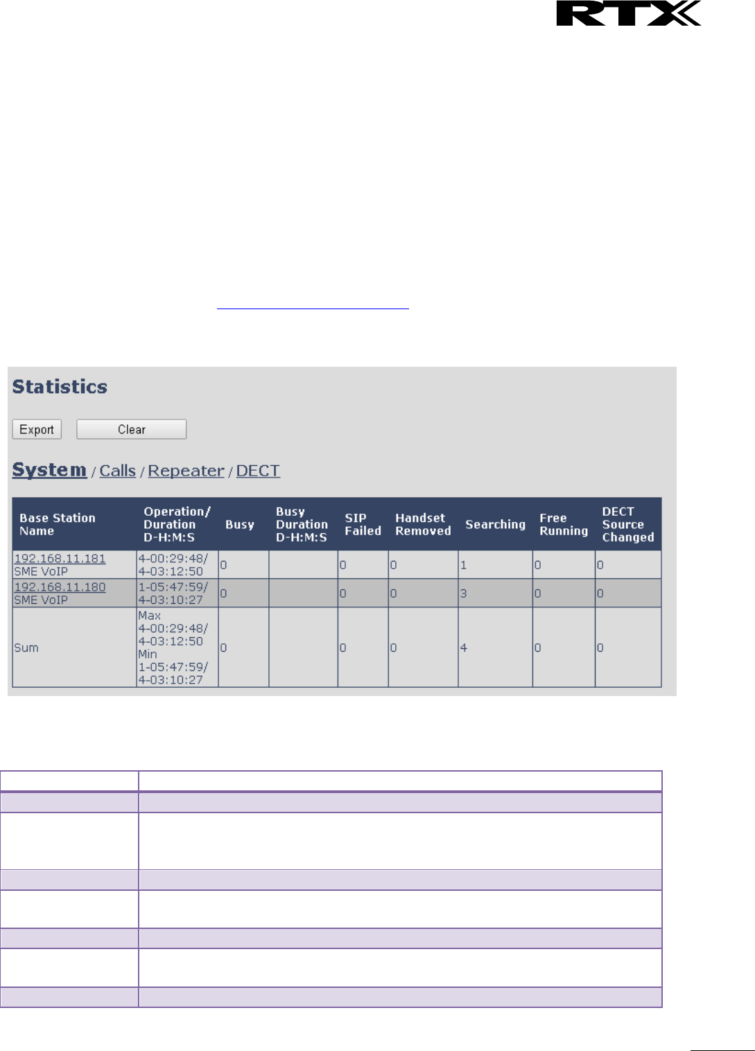
SME VoIP System Guide, Version 2.6
Proprietary and Confidential
Chapter: SME VoIP Administration Interface
70
5.15 Statistics
The statistic feature is divided into four administrative web pages, which can be access from any base.
1. System
2. Calls
3. Repeater
4. DECT data
All four views have an embedded export function, which export all data to comma separated file.
By pressing the clear button all data in the full system is cleared.
5.15.1 System data
The system data web is access by http://ip/SystemStatistics.html and data is organised in a table as shown
in below example.
Screenshot
The table is organised with headline row, data pr. base rows and with last row containing the sum of all
base parameters.
Parameters
Description
Base Station Name
Base IP address and base station name from management settings
Operation/Duration
D-H:M:S
Operation is operation time for the base since last reboot.
Duration is the operation time for the base since last reset of statistics, or
firmware upgrade.
Busy
Busy Count is the number of times the base has been busy.
Busy Duration
D-H:M:S
Busy duration is the total time a base has been busy for speech (8 or more calls
active).
SIP Failed
Failed SIP registrations count the number of times a SIP registration has failed
Handset Removed
Handset removed count is the number of times a handset has been marked as
removed
Searching
Base searching is the number of times a base has been searching for it’s sync
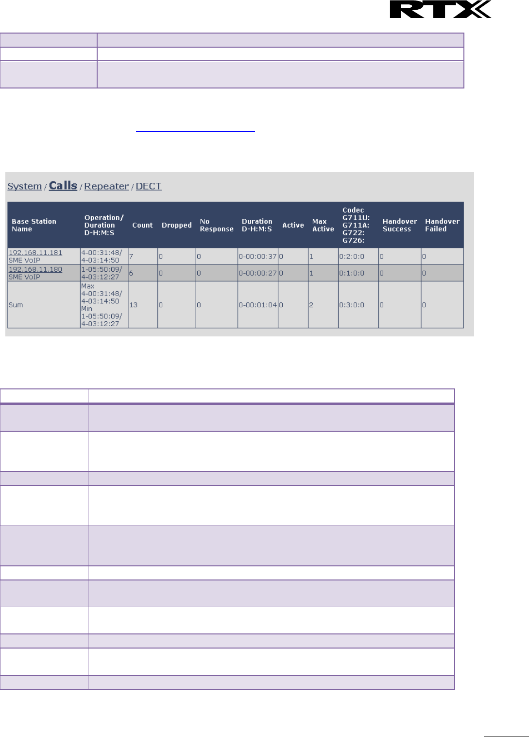
SME VoIP System Guide, Version 2.6
Proprietary and Confidential
Chapter: SME VoIP Administration Interface
71
source
Free Running
Base free running is the number of times a base has been free running
DECT Source
Changed
Number of time a base has changed sync source
5.15.2 Call data
The call data web is access by http://ip/CallStatistics.html and data are organised in a table as shown in
below example.
Screenshot
The table is organised with headline row, data pr. base rows and with last row containing the sum of all
base parameters.
Parameters
Description
Base Station
Name
Base IP address and base station name from management settings
Operation
time/Duration
Total operation time for the base since last reboot or reset
Duration is the time from data was cleared or system has been firmware
upgraded.
Count
Counts number of calls on a base.
Dropped
Dropped calls are the number of active calls that was dropped.
E.g. if a user has an active call and walks out of range, the calls will be counted as
a dropped call. An entry is stored in the syslog when a call is dropped.
No response
No response calls is the number of calls that have no response, e.g. if a external
user tries to make a call to a handset that is out of range the call is counted as no
response. An entry is stored in the syslog when a call is no response.
Duration
Call duration is total time that calls are active on the base.
Active
Active call shows how many active calls that are active on the base (Not active
DECT calls, but active calls). On one base there can be up to 30 active calls.
Max Active
Maximum active calls are the maximum number of calls that has been active at
the same time.
Codecs
Logging and count of used codec types on each call.
Handover
Success
Counts the number of successful handovers.
Handover Failed
Counts the number of failed handovers.
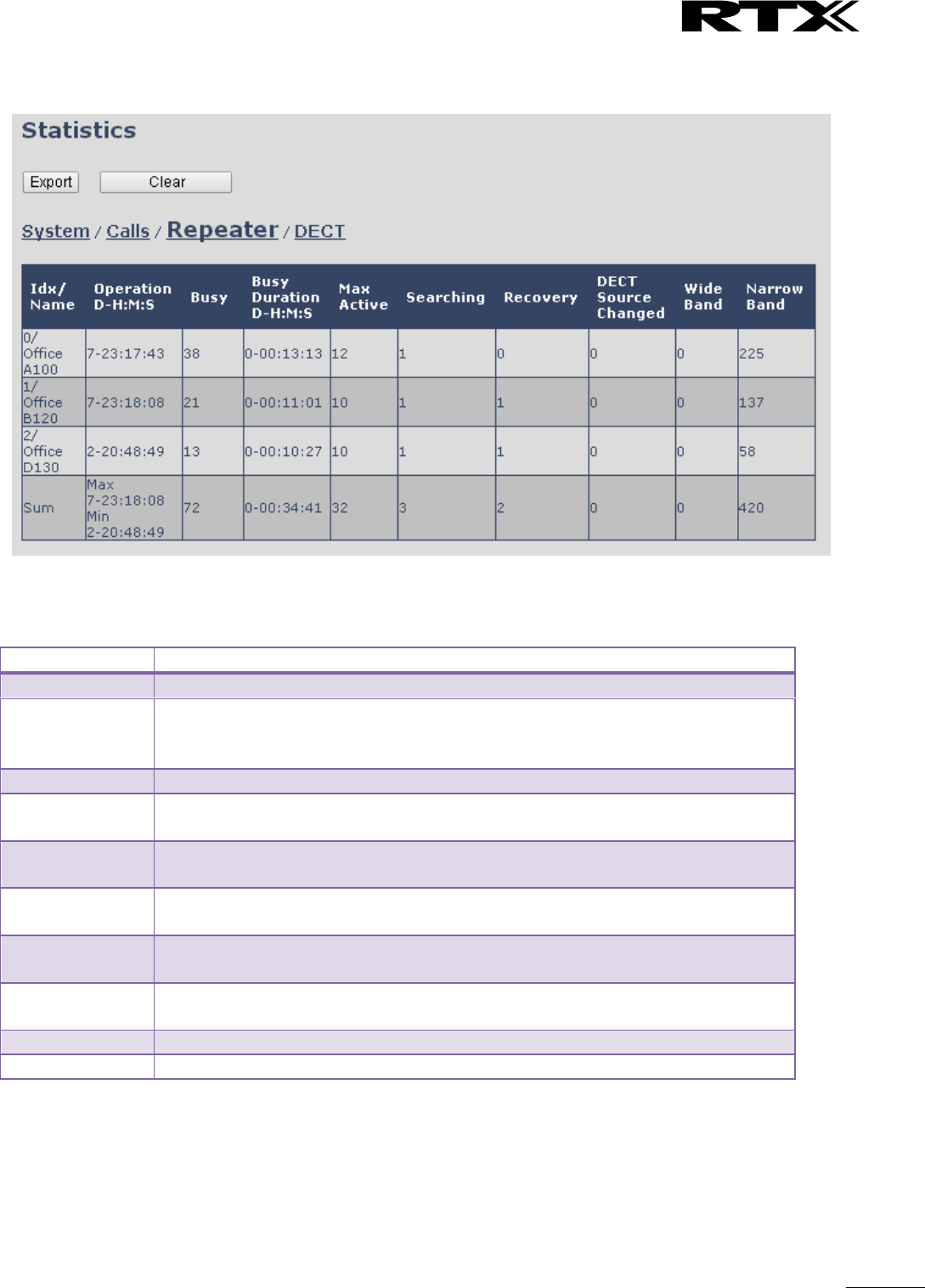
SME VoIP System Guide, Version 2.6
Proprietary and Confidential
Chapter: SME VoIP Administration Interface
72
5.15.3 Repeater data
The table is organised with headline row, data pr. base rows and with last row containing the sum of all
base parameters.
Parameters
Description
Idx/Name
Base IP address and base station name from management settings
Operation
D-H:M:S
Total operation time for the repeater since last reboot or reset
Duration is the time from data was cleared or system has been firmware
upgraded.
Busy
Busy Count is the number of times the repeater has been busy.
Busy Duration
D-H:M:S
Busy duration is the total time a repeater has been busy for speech (5 or more
calls active).
Max Active
Maximum active calls are the maximum number of calls that has been active at
the same time.
Searching
Repeater searching is the number of times a repeater has been searching for it’s
sync source
Recovery
In case the sync source is not present anymore the repeater will go into lock on
another base or repeater and show recovery mode
DECT Source
Changed
Number of time a repeater has changed sync source
Wide Band
Number of wideband calls on repeaters
Narrow Band
Number of narrow band calls on repeaters
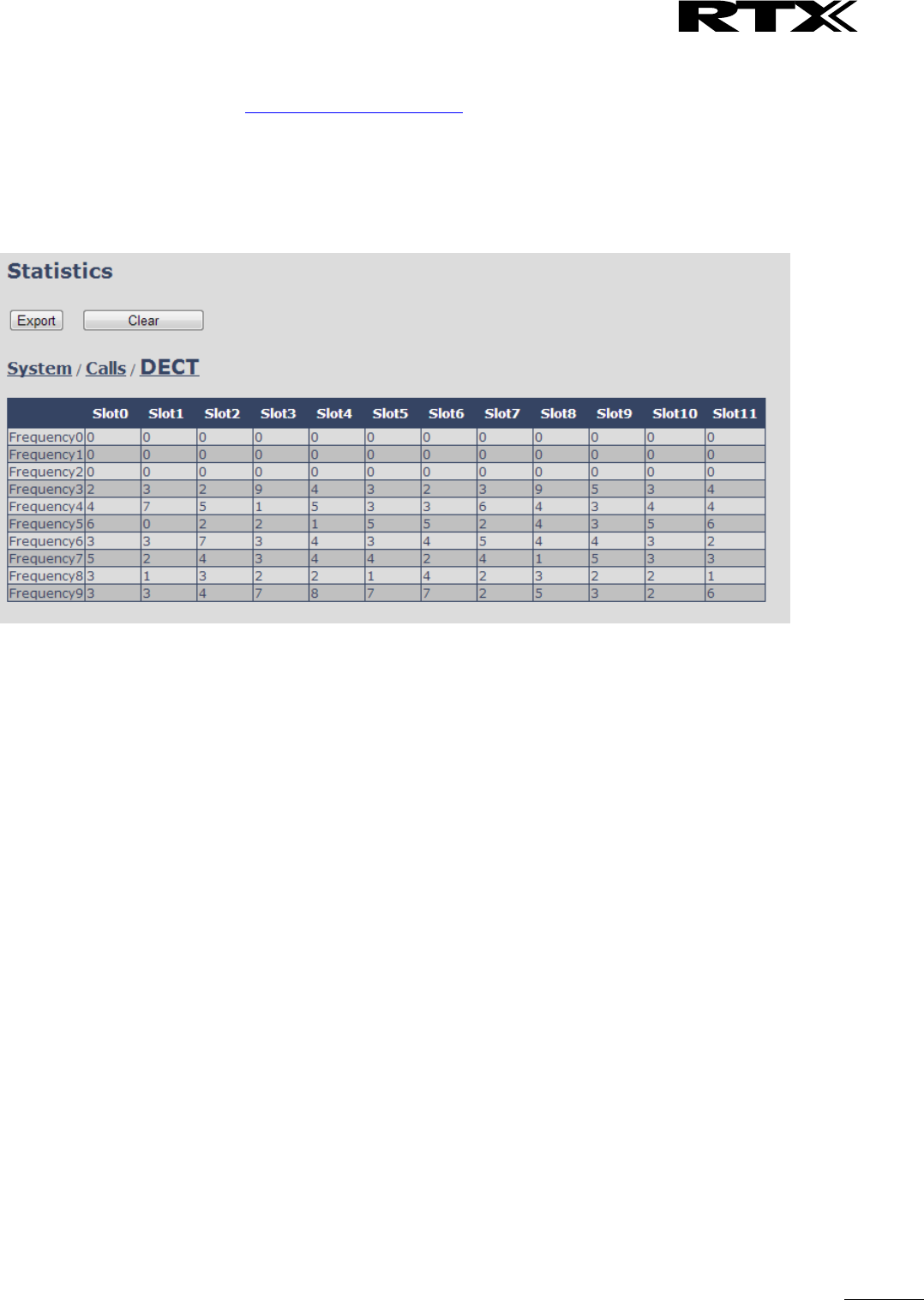
SME VoIP System Guide, Version 2.6
Proprietary and Confidential
Chapter: SME VoIP Administration Interface
73
5.15.4 DECT data
The DECT data web is access by http://ip/DectStatistics.html and data is organised in a table as shown in
below example.
Screenshot
Please note 3 frequencies are manually removed in the example system.

SME VoIP System Guide, Version 2.6
Proprietary and Confidential
Chapter: SME VoIP Administration Interface
74
5.16 Settings – Configuration File Setup
This page provides non editable information showing the native format of entire SME VoIP Configuration
parameter settings. The settings format is exactly what is used in the configuration file. The configuration
file is found in the TFTP server.
The filename for the configuration server is <MAC_Address>.cfg. The configuration file is saved in the
folder /Config in the TFTP sever.
There are three ways to edit the configuration file or make changes to the settings page:
1) Using the SME VoIP Configuration interface to make changes. Each page of the HTTP web interface
is a template for which the user can customise settings in the configuration file.
2) Retrieving the relevant configuration file from the TFTP and modify and enter new changes. This
should be done with an expert network administrator.
3) Navigate to the settings page of the VoIP SME Configuration interface > copy the contents of
settings > save them to any standard text editor e.g. notepad > modify the relevant contents, make
sure you keep the formatting intact > Save the file as <Enter_MAC_Address_of_RFP>.cfg > upload
it into the relevant TFTP server.
For details refer to [3].
An example of contents of settings is as follows:
~RELEASE=UMBER_FP_V0054
%GMT_TIME_ZONE%:16
%COUNTRY_VARIANT_ID%:18
%FWU_POLLING_ENABLE%:0
%FWU_POLLING_MODE%:0
%FWU_POLLING_PERIOD%:86400
%FWU_POLLING_TIME_HH%:3
%FWU_POLLING_TIME_MM%:0
%DST_ENABLE%:2
%DST_FIXED_DAY_ENABLE%:0
%DST_START_MONTH%:3
%DST_START_DATE%:1
....
....
5.17 Sys log
This page shows live feed of system level messages of the current base station. The messages the
administrator see here depends on what is configured at the Management settings. The Debug logs can
show only Boot Log or Everything that is all system logs including boot logs.
The Debug log is saved in the file format <Time_Stamp>b.log in a relevant location in the TFTP server as
specified in the upload script.
A sample of debug logs is as follows:
0101000013 [N](01):DHCP Enabled
0101000013 [N](01):IP Address: 192.168.10.101
0101000013 [N](01):Gateway Address: 192.168.10.254
0101000013 [N](01):Subnet Mask: 255.255.255.0
0101000013 [N](01):TFTP boot server not set by DHCP. Using Static.
0101000013 [N](01):DHCP Discover completed
0101000013 [N](01):Time Server: 192.168.10.11
0101000013 [N](01):Boot server: 10.10.104.63 path: Config/ Type: TFTP
0101000013 [N](01):RemCfg: Download request of Config/00087b077cd9.cfg from
10.10.104.63 using TFTP

SME VoIP System Guide, Version 2.6
Proprietary and Confidential
Chapter: SME VoIP Administration Interface
75
0101000014 [N](01):accept called from task 7
0101000014 [N](01):TrelAccept success [4]. Listening on port 10010
0101000019 [N](01):RemCfg: Download request of Config/00087b077cd9.cfg from
10.10.104.63 using TFTP
0101000019 [W](01):Load of Config/00087b077cd9.cfg from 10.10.104.63 failed
To dump the log simply copy and page the full contents.
5.18 SIP Logs
This page shows SIP server related messages that are logged during the operation of the SME system. The
full native format of SIP logs is saved in the TFTP server as <MAC_Address><Time_Stamp>SIP.log
These logs are saved in 2 blocks of 17Kbytes. When a specific SIP log is fully dumped to one block, the next
SIP logs are dumped to the other blocks. An example of SIP logs is shown below:
.....
Sent to udp:192.168.10.10:5080 at 12/11/2010 11:56:42 (791 bytes)
REGISTER sip:192.168.10.10:5080 SIP/2.0
Via: SIP/2.0/UDP 192.168.10.101:5063;branch=z9hG4bKrlga4nkuhimpnj4.qx
Max-Forwards: 70
From: <sip:Ext003@192.168.10.10:5080>;tag=3o5l314
To: <sip:Ext003@192.168.10.10:5080>
Call-ID: p9st.zzrfff66.ah8
CSeq: 6562 REGISTER
Contact: <sip:Ext003@192.168.10.101:5063>
Allow: INVITE, CANCEL, BYE, ACK, REGISTER, OPTIONS, REFER, SUBSCRIBE, NOTIFY,
MESSAGE, INFO, PRACK
Expires: 120
User-Agent: Generic-DPV-001-A-XX(Generic_SIPEXT2MLUA_v1)
Content-Type: application/X-Generic_SIPEXT2MLv1
Content-Length: 251
.....
To dump the log simply copy and page the full contents.
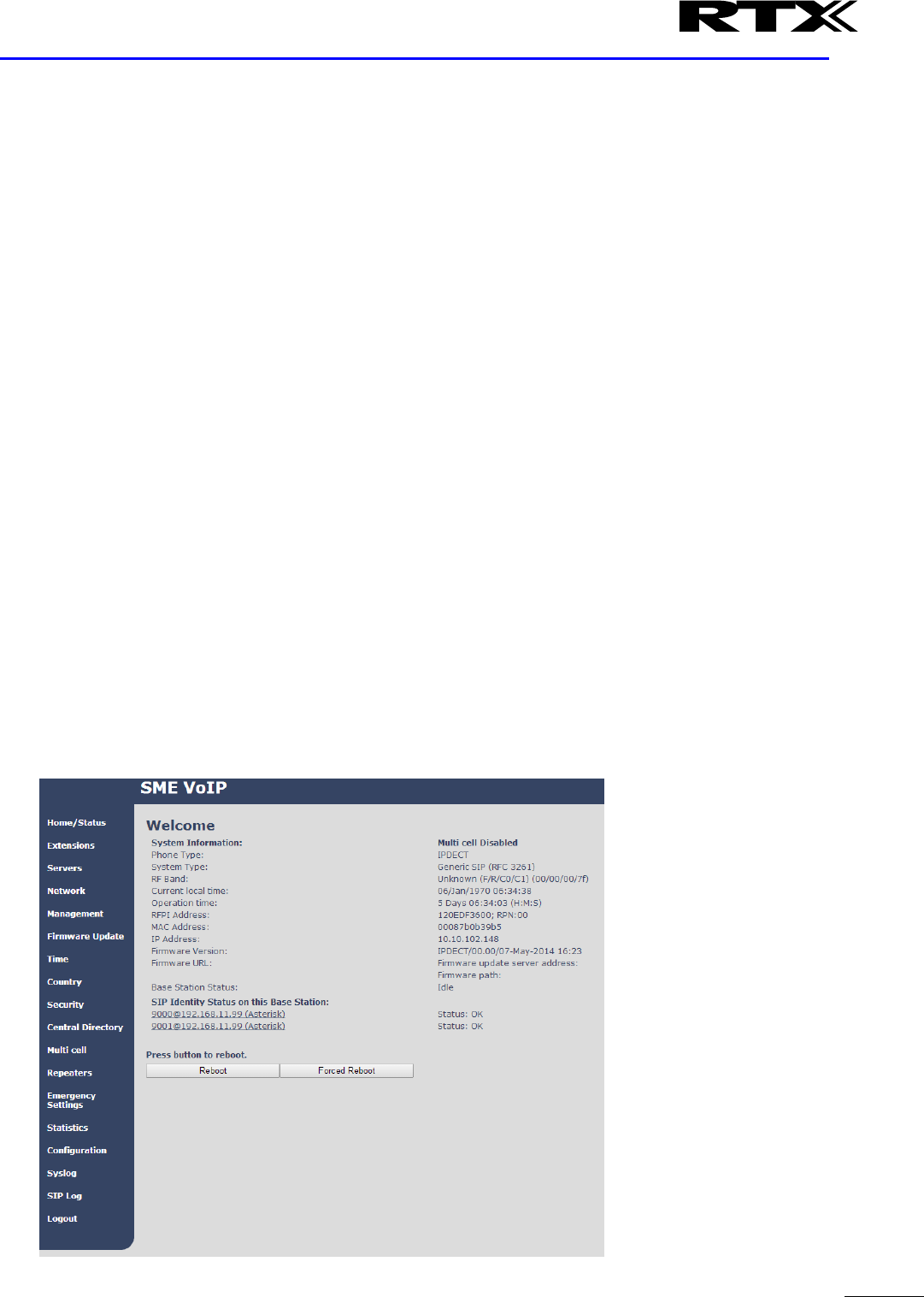
SME VoIP System Guide, Version 2.6
Proprietary and Confidential
Chapter: Multi-cell Setup & Management
76
6 Multi-cell Setup & Management
This chapter seeks to describe how to install, add and synchronize one or multiple base stations to the
network. There are two main procedures involved:
1) Proper placement of the base stations (which is called network dimensioning). The present chapter
does not address this issue. Refer to Chapter 12 for details.
2) Creating and adding base station profiles to the network via the SME Configuration Tool (to form a
multi-cell system).
This chapter describes the second procedure.
6.1 Adding Base stations
Here are the recommended steps to add Base stations to network:
STEP 1 Connect the Base station to a private network via standard Ethernet cable (CAT-5).
STEP 2 Use one of the two methods to determine the base station IP address.
a. Use the IP find menu in the handset (Menu * 4 7 *) to determine the IP address of the base
station by matching the MAC address on the back of the base station with the MAC address
list in the handset.
b. Use the IPdect feature
STEP 3 Open browser on the computer and type in the IP address of the base. Press “Enter” to
access the base Login to base station.
STEP 4 Once you have authenticated, the browser will display front end of the SME Configuration
Interface. The front end will show relevant information of the base station.
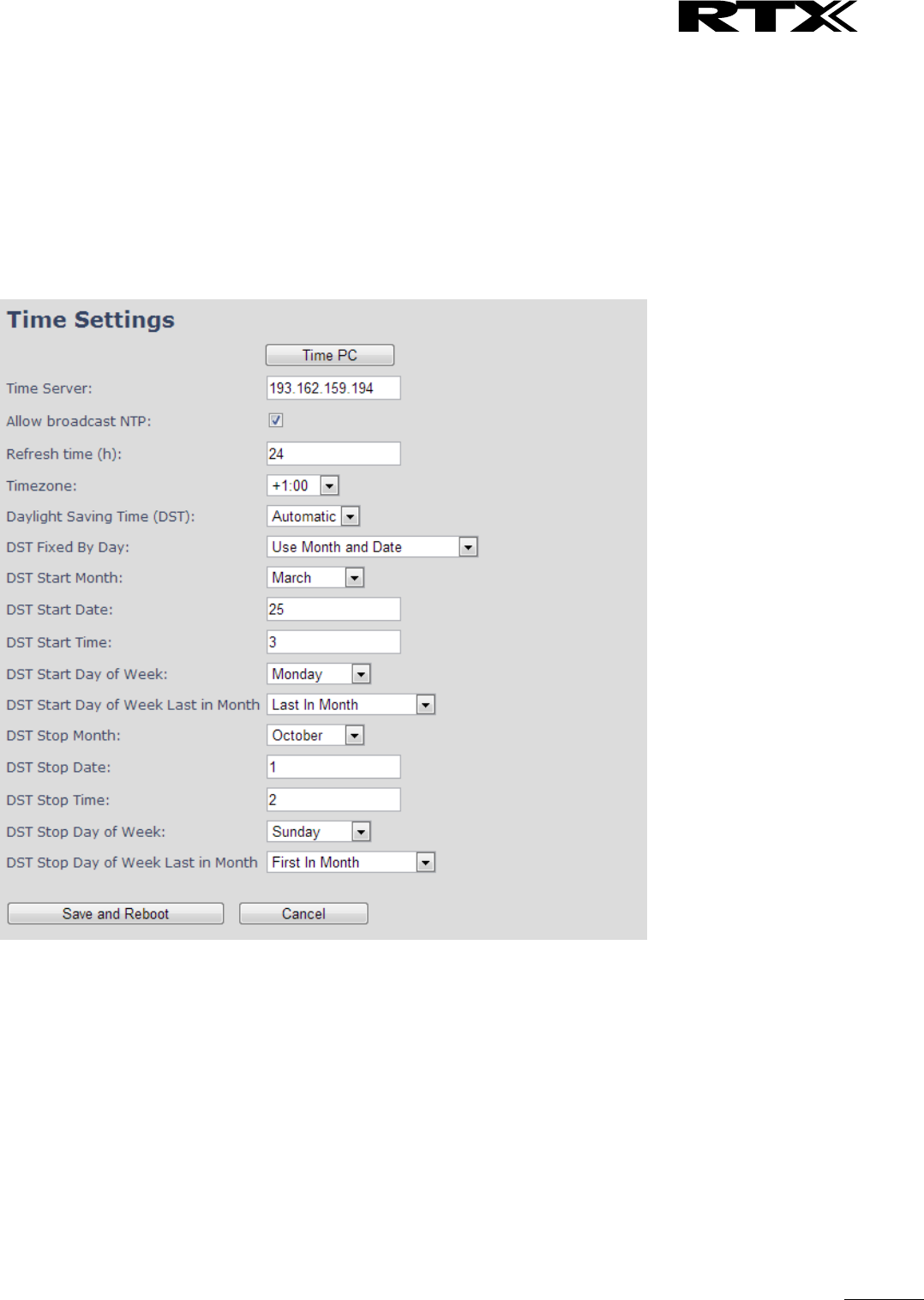
SME VoIP System Guide, Version 2.6
Proprietary and Confidential
Chapter: Multi-cell Setup & Management
77
6.1.1 Time Server Setup
STEP 5 Navigate to the Time settings and configure it. Scroll on the left column and click on Time url
link to Open the Time Settings Page. Use the PC time feature or enter the relevant
parameters on this page and press the Save and Reboot button.
Make sure there is contact to the “Time server” otherwise the Multi-cell feature will not
work.
You can verify whether the Time server is reachable af rebooting the base station by
verifying the correct Time Server IP address is still in place.
6.1.2 SIP Server (or PBX Server) Setup
STEP 6 Create the relevant SIP server (or PBX Server) information in the system. Each service
provider/customer should refer SIP server vendor on how to setup SIP servers.
Click the link “Server” at the left hand column of home page, you can add your SIP server for base
station use.
Next, from the Server page, click on the Add Server URL and enter the relevant SIP server
information (an example is shown below).
Choose “Disabled” on NAT adaption parameter if NAT function of the SIP aware router is not
enabled. Enter the relevant parameters based on the description in the table below. Select Save
button.
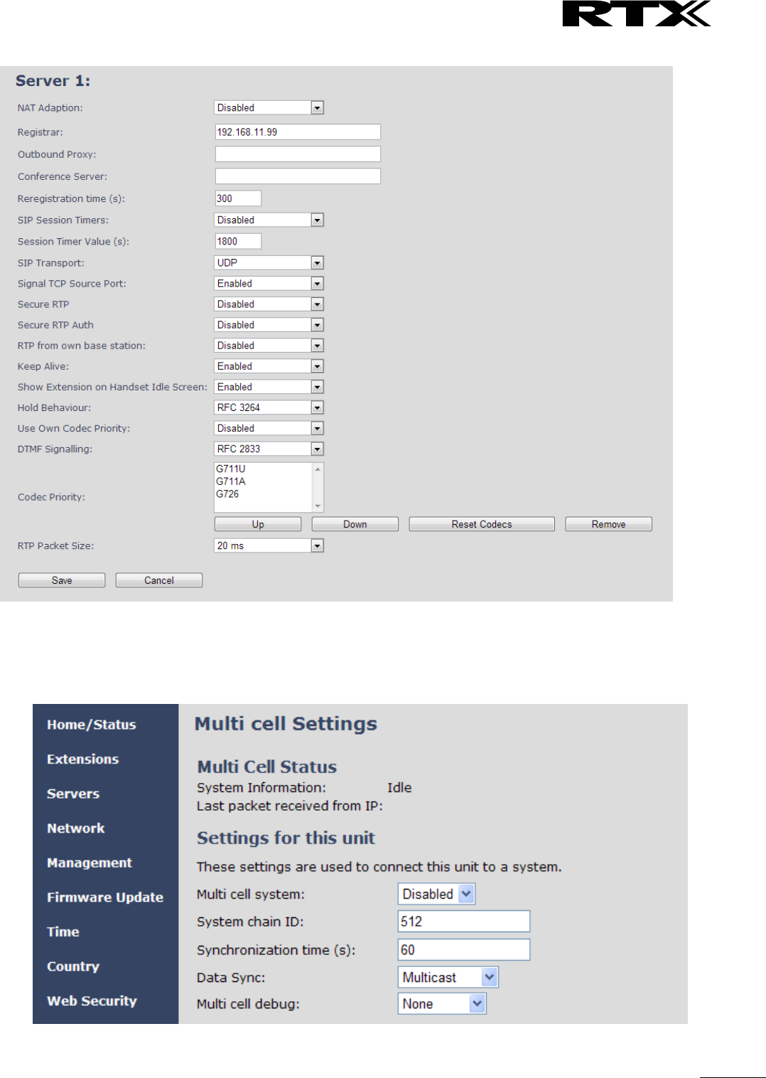
SME VoIP System Guide, Version 2.6
Proprietary and Confidential
Chapter: Multi-cell Setup & Management
78
6.1.3 Multi-cell Setup
STEP 7 Click on Multi Cell url link in the SME VoIP Configuration to view the current Multi cell
settings status of the current base station. Brand new base stations have Multi cell system
feature disabled by default.
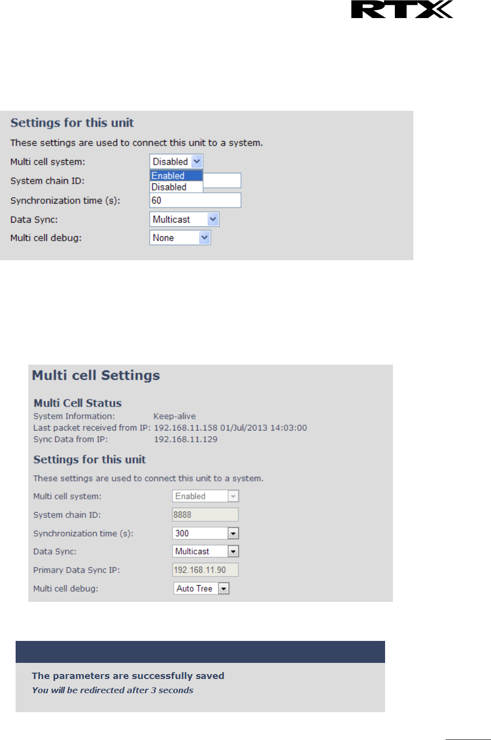
SME VoIP System Guide, Version 2.6
Proprietary and Confidential
Chapter: Multi-cell Setup & Management
79
STEP 8 Next, the system administrator needs to create and Enable Multi Settings profile for the
current base station. On the Multi Cell settings Page, choose Enable option from the drop
down menu of the Multi cell system parameter. Enable the Multi cell debug option if the
system administrator wants some Multi-cell related logs to be catalogued by the system.
STEP 9 On the same Multi Cell Settings page > Enter the relevant values for System chain ID and
Synchronization time (s) respectively. The System chain ID is a geographically unique DECT
cell identity allocated to bridge several base stations together in a chain. An example is
55555. The Synchronization time (s) parameter is defined as window/period of time in
seconds a specific base station synchronises to the master base station unit (by default 60).
Note: Do NOT use a chain ID similar to an extension.
Click on Save button to keep modified changes of multi cell settings into the base station.
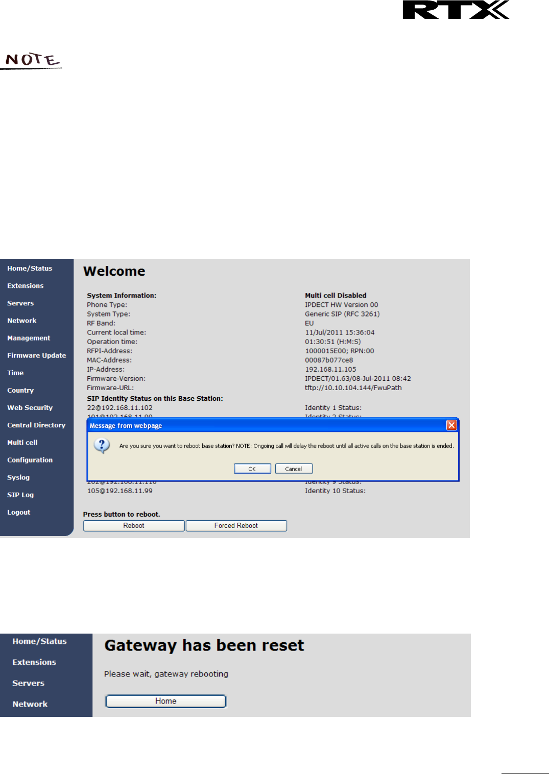
SME VoIP System Guide, Version 2.6
Proprietary and Confidential
Chapter: Multi-cell Setup & Management
80
The Multi Cell data synchronization ONLY works when the relevant Time Server is set in
the system before Server/Subscriber profile is added or created. Refer to STEP 5.
IMPORTANT: Base stations must be rebooted after the time server has been set.
STEP 10 Repeat STEP 1-9 as explained above for each base stations.
IMPORTANT: It takes up to 5 minutes (synchronization time) to add a new base station to a Multi Cell
System.
6.2 Synchronizing the Base stations
STEP 11 On each SME VoIP Configuration interface for the base station(s) navigate to the
Home/Status page and Click the Reboot button.
This will trigger Are you sure you want to reboot base station? window. Click OK button on
this window. A successful restart of the base stations will lead to a display of the page:
Gateway has been reset.
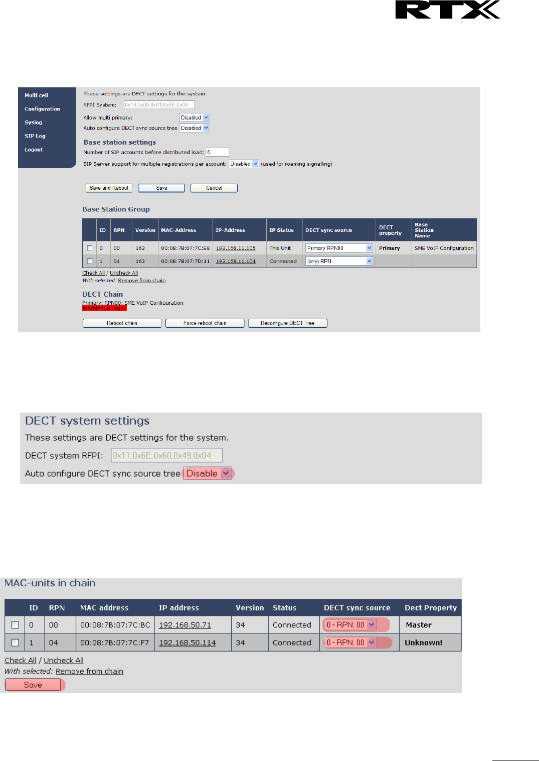
SME VoIP System Guide, Version 2.6
Proprietary and Confidential
Chapter: Multi-cell Setup & Management
81
STEP 12 Navigate back to the Multi cell settings page by clicking Multi-cell url link at the left column.
The revised Multi cell settings page shows the relevant base stations synchronized together.
By default, the system uses the first registered base station as the master base unit.
STEP 13 On the Multi-cell settings page, scroll to the DECT system settings and Enable or Disable the
“Auto configure DECT sync option source tree” (See description in the table below). The
DECT system RFPI parameter is computed by the system (It’s often greyed in a multi-cell
system configuration).
STEP 14 Next, on the MAC-units in chains section, you can manually configure the synchronisation
source tree of the multi-cell system. Multi-cell settings page, scroll to the DECT system settings and
Enable or Disable the “Auto configure DECT sync option source tree” (See description in the table
below). The DECT system RFPI parameter is computed by the system (Its often greyed in a multi-cell
system)

SME VoIP System Guide, Version 2.6
Proprietary and Confidential
Chapter: Multi-cell Setup & Management
82
6.3 Summary of Procedure – Creating a Chain
We enumerate the short version of how to add 3 base stations units in a multi-cell setup. This can be
applied for up to 40 number of base units.
This procedure is divided into four (4) main stages. Apply this procedure if all base unit are straight from
production.
6.3.1 Stage 1
Skip this stage if relevant base stations are already in the network.
a) Add 3 base stations i.e. RFP1, RFP2, RFP3 > Disable the “Multi cell system” option and “Save”
b) RFP1, RFP2, RFP3: Reboot from the HTTP SME Configuration Main Page
c) RFP1, RFP2, RFP3: Default by pressing reset button 12-sec.
6.3.2 Stage 2
Choosing 1st base unit i.e. RFP1 as Primary
a) RFP1: Define Time server and “Save and reboot” from the Time page
b) RFP1: Reboot automatically
c) RFP1: Press “Add server” and define SIP server IP and “Save” from the Servers page
d) RFP1: On the extension page add one extension (no handset needs to be registered). This step is
important for allow secondary base to join
e) RFP1: Multi cell system = enable and “Save” from the Multi-cell page
f) RFP1: Reboot (Verify from Debug log “SYNCMGR: This base is ready to be Primary in a Chain”)
6.3.3 Stage 3
Choose another base unit,RFP2 as Secondary
a) RFP2: Select chain ID same as RFP1.
b) RFP2: Multi cell system = enable and “Save”
c) RFP2: Reboot (Verify from Debug log “SYNCMGR: This base is ready to join into another Chain”)
d) RFP1, RFP2: Wait 2min for stable Primary-Secondary chain (check for the message: SYNCMGR:
Socket#10 creation success)
6.3.4 Stage 4
Choose the 3rd base unit, RFP3 as Secondary
e) RFP3: Multi cell system = enable and “Save”
f) RFP3: Reboot (Verify Debug log “SYNCMGR: This base is ready to join into another Chain”)
g) RFP1, RFP3: Wait 2min for stable Master-Slave chain (SYNCMGR: Socket#10 creation success)
h) RFP3: Check mark ID2/RPN08 and select dropdown “1 – RPN: 04” and “Save”
i) RFP3: Reboot (SYNCMGR: Socket#8 creation success)
Multi-cell chain of 3 base stations has been created successfully. Next step involves adding extensions to
the system.
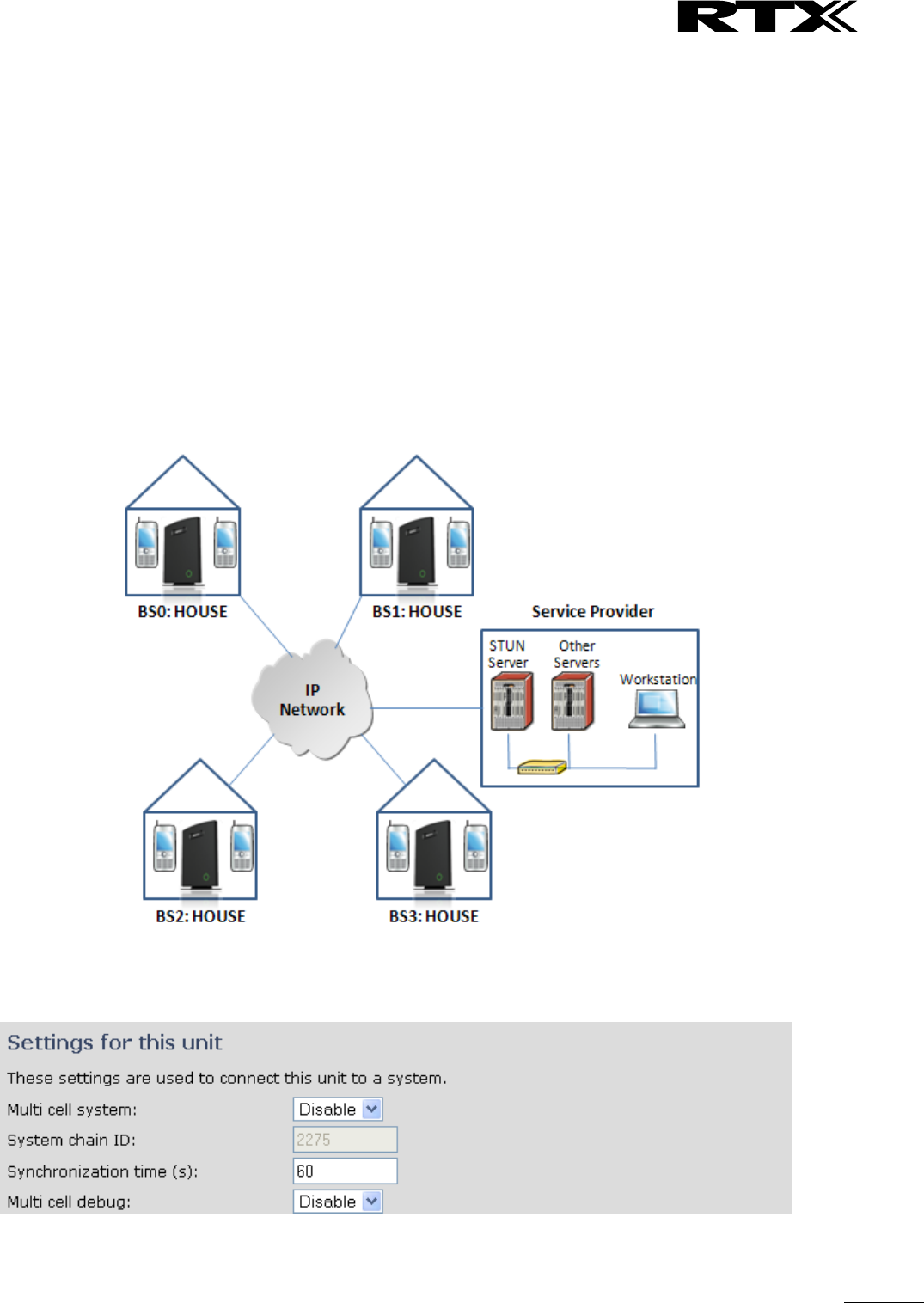
SME VoIP System Guide, Version 2.6
Proprietary and Confidential
Chapter: Multi-cell Setup & Management
83
6.4 Practical Configuration of Multi-cell System
In this chapter we describe what exactly to configure in the SME VoIP Configuration Interface ensure these
scenarios really work.
6.4.1 Case ##1: Isolated Buildings
The optimal configuration for isolated buildings is standalone base stations setting. In this setting, you
must:
A. Using the figure below as illustration, log into the Configuration Interface of each base station.
B. Configure the Time Server, SIP Server, Extensions as described in the previous chapters.
C. On the main page of the configuration interface, click Network URL > disable the Multi-cell
parameter of each base station > Save and Reboot each base to complete the Case ##1 setup.
Disable Multi Cell option of Base Stations
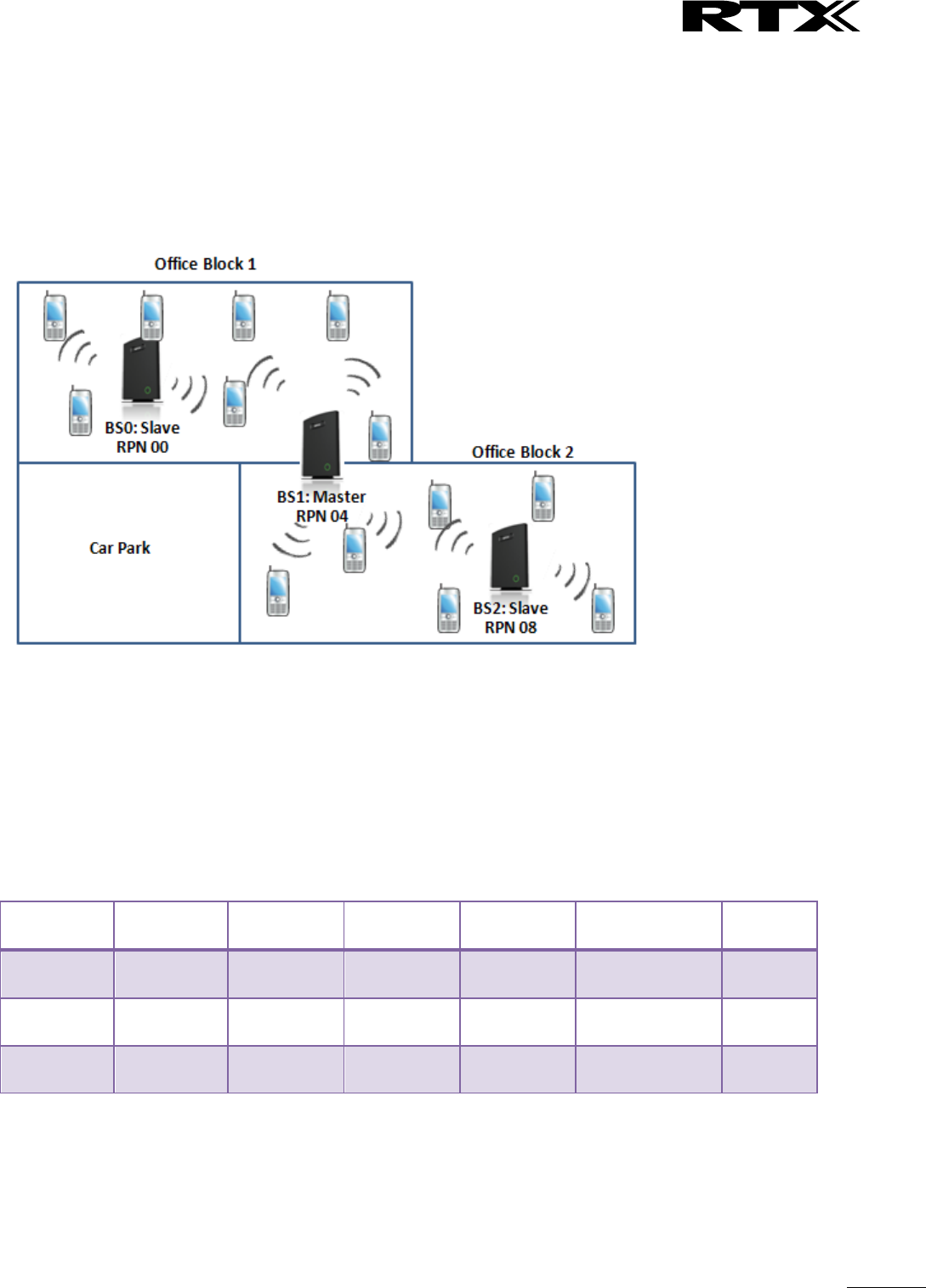
SME VoIP System Guide, Version 2.6
Proprietary and Confidential
Chapter: Multi-cell Setup & Management
84
6.4.2 Case ##2: Location with co-located partners
Example includes Department shops, Retail location with co-located photo kiosk or pharmacy, etc.
To illustrate this setup, two slave base stations are synchronised to one master base in the two office
blocks.
Here is diagram to illustrate Case ##2.
The procedure:
STEP 1 Follow the steps described in section 0
STEP 2 On the Network page of each base define the DECT sync source settings as illustrated in the
table below.
STEP 3 Save and reboot each base to complete case ##2 setup
Multi Cell Page of Base Stations
Recommended settings of MAC-units in Chain section of page (Other different settings exist):
RPN
Ver
MAC Addr
IP Addr
IP Status
DECT sync
source
DECT
Property
00
XX
XX:XX:XX…
XXX.XXX…
Connected
1: RPN:04
04
XX
XX:XX:XX…
XXX.XXX…
Connected
1: RPN:04
Primary
08
XX
XX:XX:XX…
XXX.XXX…
Connected
1: RPN:04
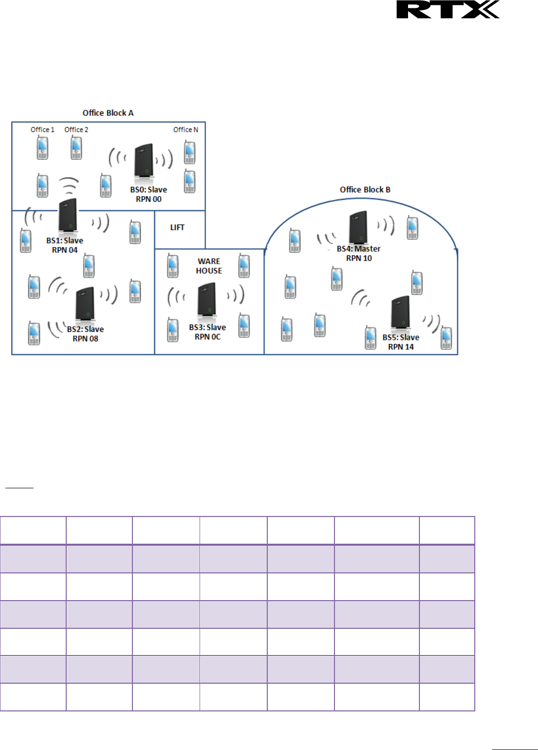
SME VoIP System Guide, Version 2.6
Proprietary and Confidential
Chapter: Multi-cell Setup & Management
85
6.4.3 Case ##3: Large to Medium Sized Enterprises
In this scenario, we have five slave bases synchronised to one master base. The master base is located in
office block B while the slave bases are spread across the whole enterprise. No base station is deployed in
the lift because it has high attenuation properties that will drastically reduce radio signals.
The procedure:
STEP 1 Follow the steps described in sections 0
STEP 2 On the Network page of each base define the DECT sync source settings as illustrated in the
table below.
STEP 3 Save and reboot each base to complete case ## 3 setup
Multi Cell Page of Base Stations
Recommended settings of MAC-units in Chain section of page (Other valid setting exists):
NOTE:
The number of chains cannot exceed 24 levels.
RPN
Ver
MAC Addr
IP Addr
IP Status
DECT sync
source
DECT
Property
00
XX
XX:XX:XX…
XXX.XXX…
Connected
1: RPN:04
04
XX
XX:XX:XX…
XXX.XXX…
Connected
2: RPN:08
08
XX
XX:XX:XX…
XXX.XXX…
Connected
3: RPN:0C
0C
XX
XX:XX:XX…
XXX.XXX…
Connected
4: RPN:10
10
XX
XX:XX:XX…
XXX.XXX…
Connected
4: RPN:10
Primary
14
XX
XX:XX:XX…
XXX.XXX…
Connected
4: RPN:10
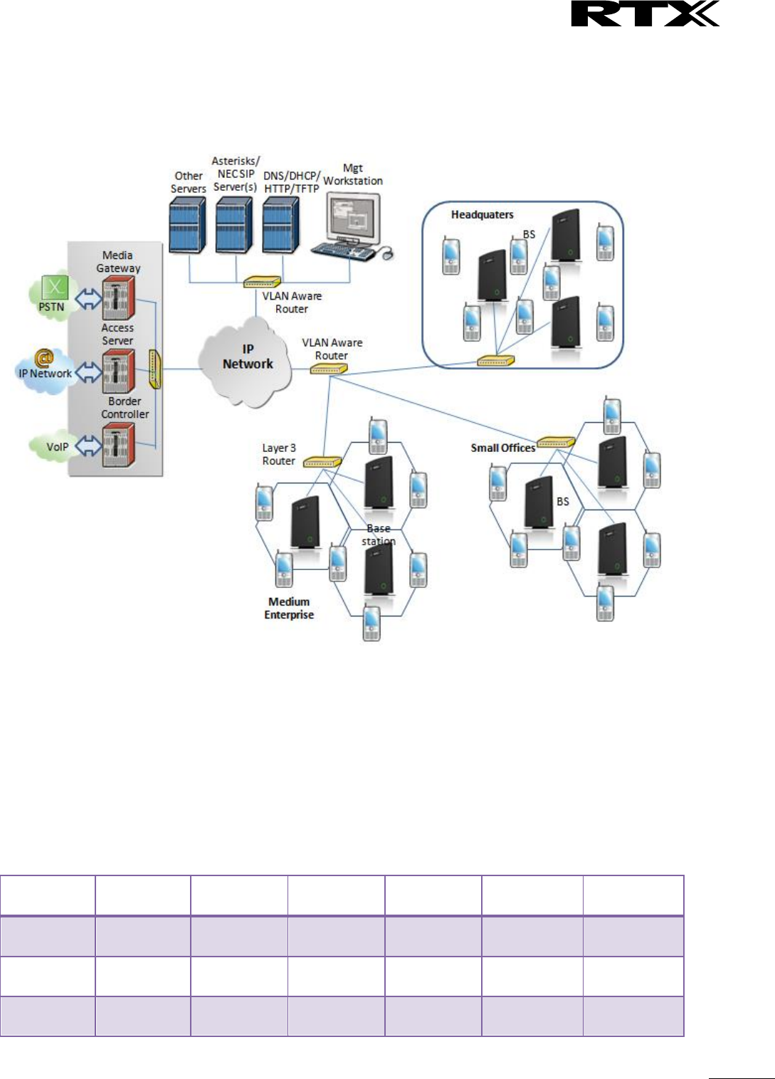
SME VoIP System Guide, Version 2.6
Proprietary and Confidential
Chapter: Multi-cell Setup & Management
86
6.4.4 Case ##4: Large Enterprises at Different Locations
In this scenario, multi-cell systems are deployed at different locations; geographically separated from each
other. Each location has a master base station with more than one slave base synchronise to it.
The procedure:
STEP 1 Follow the steps described in sections 6
STEP 2 On the Network page of each base define the DECT sync source settings as illustrated in the
table below.
STEP 3 Save and reboot each base to complete case ## 4 setup
STEP 4 Important for this configuration is to enable “Allow multi primary” on the multi cell page.
This allows the handset to locate on both systems make it possible for the user move from one
location to the other and still use the same handset.
Multi Cell Page of Base Stations
Recommended settings of MAC-units in Chain section of page (Other valid setting exists):
RPN
Ver
MAC Addr
IP Addr
IP Status
DECT sync
source
DECT
Property
00
XX
XX:XX:XX…
XXX.XXX…
Connected
0: RPN:00
Primary for
HQ
04
XX
XX:XX:XX…
XXX.XXX…
Connected
0: RPN:00
08
XX
XX:XX:XX…
XXX.XXX…
Connected
1: RPN:04

SME VoIP System Guide, Version 2.6
Proprietary and Confidential
Chapter: Multi-cell Setup & Management
87
0C
XX
XX:XX:XX…
XXX.XXX…
Connected
3: RPN:0C
Primary for
Offices
10
XX
XX:XX:XX…
XXX.XXX…
Connected
3: RPN:0C
14
XX
XX:XX:XX…
XXX.XXX…
Connected
4: RPN:10
18
XX
XX:XX:XX…
XXX.XXX…
Connected
6: RPN:18
Primary for
Enterprises
1C
XX
XX:XX:XX…
XXX.XXX…
Connected
6: RPN:18
20
XX
XX:XX:XX…
XXX.XXX…
Connected
7: RPN:1C
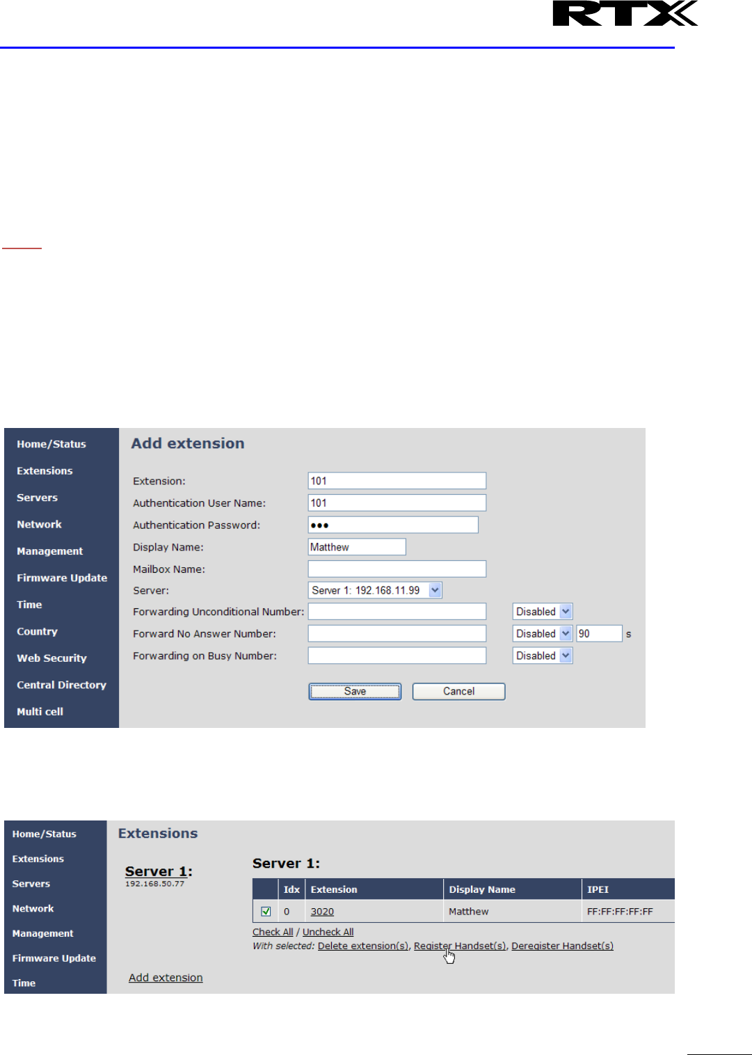
SME VoIP System Guide, Version 2.6
Proprietary and Confidential
Chapter: Registration Management - Handset
88
7 Registration Management - Handset
In this chapter we briefly describe how to register handsets in the SME VoIP Network. A precondition for
handset registration is a proper configured single or multi-base system. For this refer to chapter 6.1.
7.1 Register handset to base (non multiline)
This section describes how to register the wireless handset to the base station.
NOTE:
Minimum one server must be registered to the base (system), otherwise a handset cannot be registered to
the system. Please see chapter 6.1.2.
STEP 1 Login to a base station.
STEP 2 Select “Extensions” URL and click “Add extension” link
STEP 3 Fill out the form and click “Save”. In the example below we add the extension “3020” and
this SIP account got the same number as “Authentication User Name” and “Password”. The “Server
1” is selected by default as server for this extension.
STEP 4 In the extensions list set a Check mark on the extension which shall be assigned to the
handset you want to register and click “Register handset (s)”. The base is now open (ready state)
for handset registrations for 5 minutes.
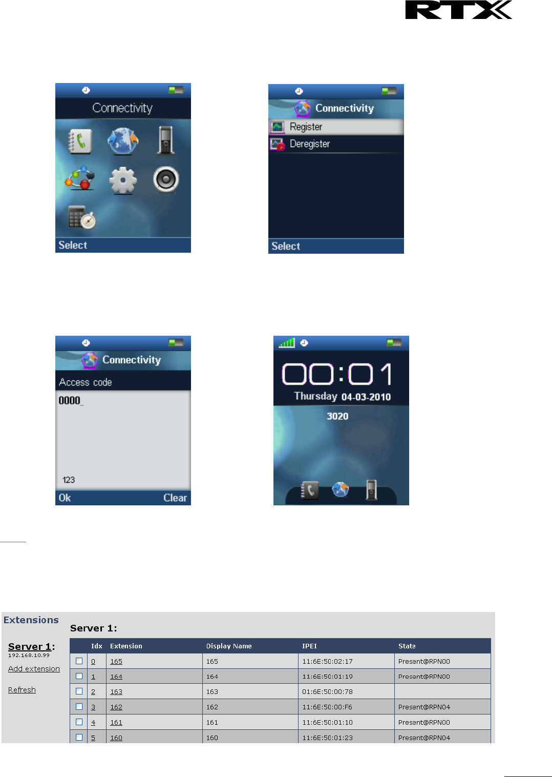
SME VoIP System Guide, Version 2.6
Proprietary and Confidential
Chapter: Registration Management - Handset
89
STEP 5 Start the registration procedure on the handset by following step “a” to “d” below.
a) Select main menu “Connectivity” b) Select menu ”Register”
c) Type in the “AC code” and press “OK”
to start the registration. The default AC code is
“0000”.
d) After a while the handset is registered,
and the idle display is shown.
NOTE:
The unique handset IPEI is displayed on sheet “Extensions” when the handset is successfully registered. The
web page must be manually updated by pressing “F5” to see that the handset is registered; otherwise the
handset IPEI (International Portable Equipment Identity) isn’t displayed on the web page.
We illustrate how extensions page will be when you register several handsets.
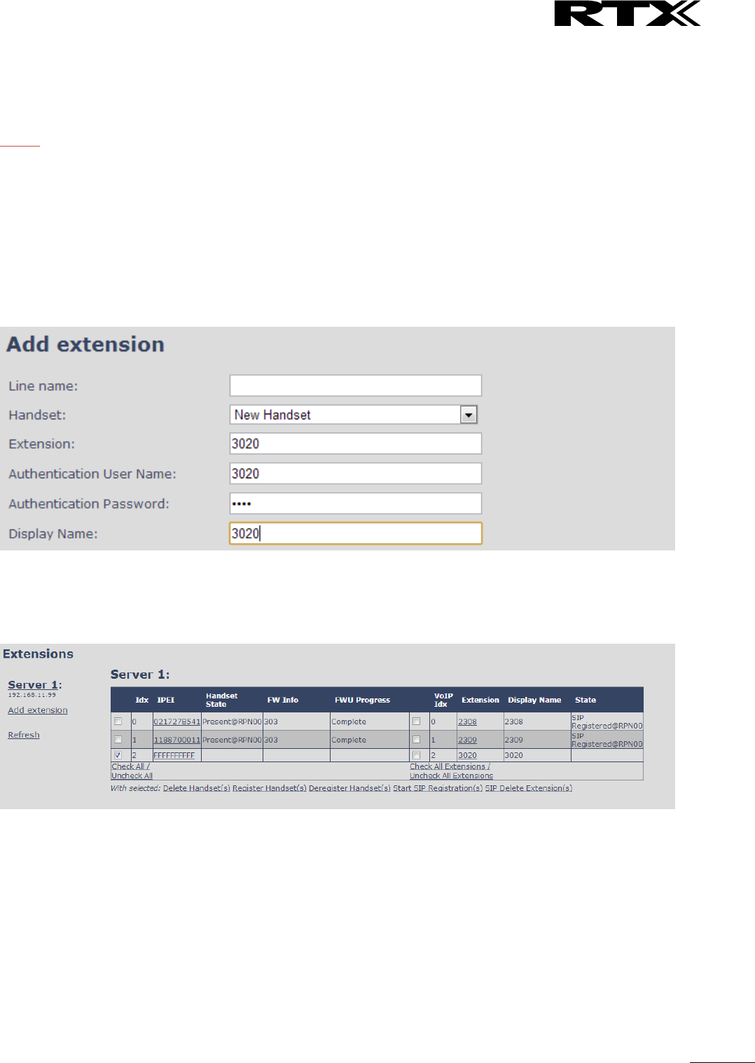
SME VoIP System Guide, Version 2.6
Proprietary and Confidential
Chapter: Registration Management - Handset
90
7.2 Register handset to base (multiline)
This section describes how to register the wireless handset to a system with active multiline feature.
NOTE:
Minimum one server must be registered to the base (system), otherwise a handset cannot be registered to
the system. Please see chapter 6.1.2.
STEP 1 Login to a base station.
STEP 2 Select “Extensions” URL and click “Add extension” link
STEP 3 Fill out the form and click “Save”. In the example below we add the extension “3020” and
this SIP account got the same number as “Authentication User Name”, “Password” and “Display
Name”.
STEP 4 In the handset and extensions list set a Check mark on the handset Idx, which you want to
register and click “Register handset (s)”. The base is now open (ready state) for handset
registrations for 5 minutes.
STEP 5 Start the registration procedure on the handset by following step “a” to “d” below.
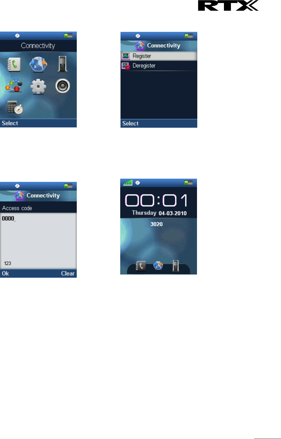
SME VoIP System Guide, Version 2.6
Proprietary and Confidential
Chapter: Registration Management - Handset
91
a) Select main menu “Connectivity” b) Select menu ”Register”
c) Type in the “AC code” and press “OK”
to start the registration. The default AC code is
“0000”.
d) After a while the handset is registered, and the
idle display is shown
STEP 6 Confirm the registration from the unique handset IPEI is displayed in column “IPEI” when the
handset is successfully registered.
Note: The web page must be manually updated by pressing “F5” to see that the handset is registered;
otherwise the handset IPEI (International Portable Equipment Identity) isn’t displayed on the web page.
STEP 7 SIP registration for first extension is made automatically. For the second extension start the
SIP registration procedure on the base by Check the extension and click “Start SIP Registration(s)”.
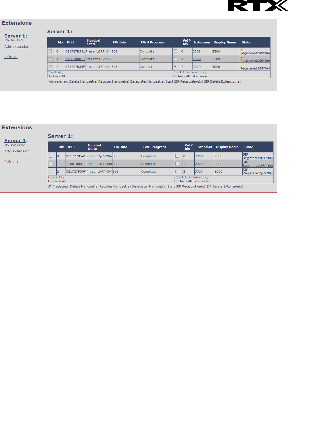
SME VoIP System Guide, Version 2.6
Proprietary and Confidential
Chapter: Registration Management - Handset
92
STEP 8 Confirm the SIP registration by SIP State in right column.
Note: The web page must be manually updated by pressing “F5” to see that the handset is SIP registered;
otherwise the handset SIP state isn’t displayed on the web page.
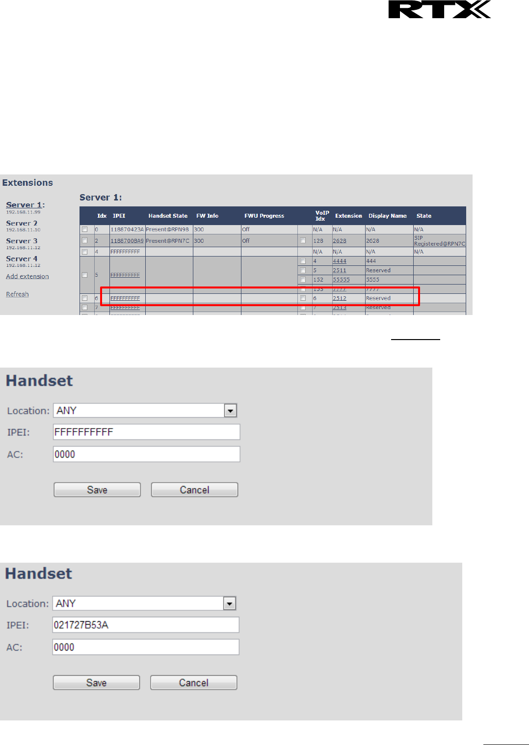
SME VoIP System Guide, Version 2.6
Proprietary and Confidential
Chapter: Registration Management - Handset
93
7.3 Register handset to base and specific extension (multiline)
This section gives an example of controlling handset registration to a specific extension.
STEP 1 Login to a base station.
STEP 2 Select “Extensions” URL and click “Add extension” link
STEP 3 Fill out the form and click “Save”. In the example below we add the extension “2512” with
display name “Reserved”
STEP 4 Extension 2512 is now listed with handset IPEI “FFFFFFFFF”. Click the IPEI “FFFFFFFFFF” link
and get the below view.
STEP 5 Enter the IPEI of handset which must register to this particular extension and press “Save”
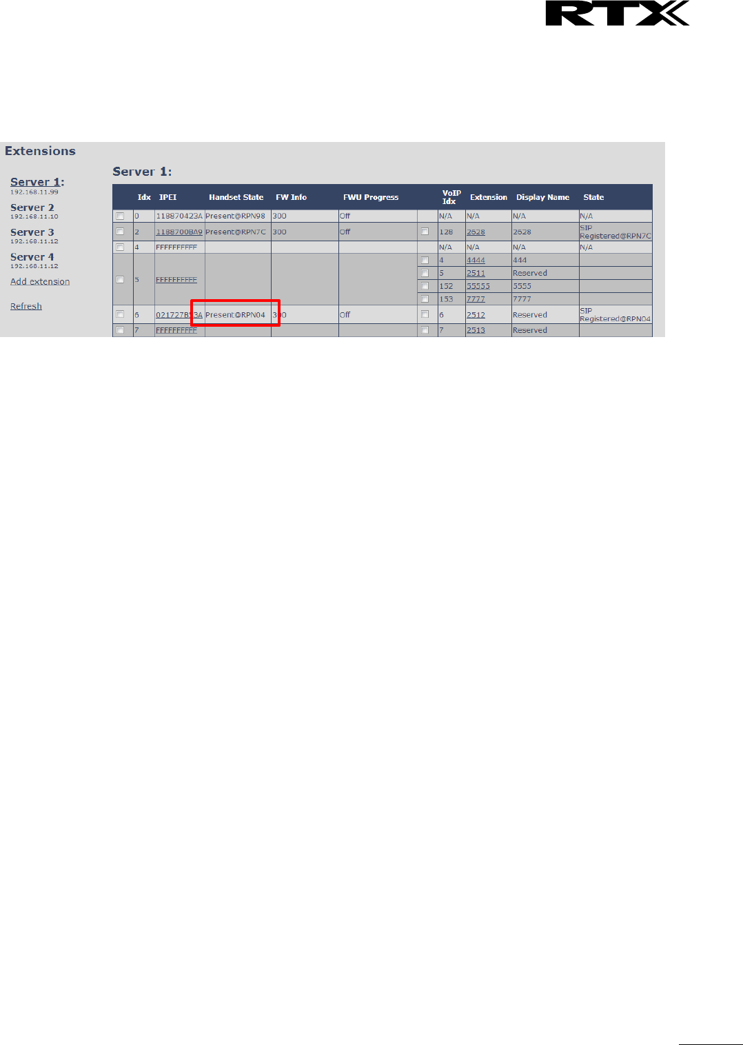
SME VoIP System Guide, Version 2.6
Proprietary and Confidential
Chapter: Registration Management - Handset
94
STEP 6 Check mark the handset Idx in left column and press “Register Handset(s)”
STEP 7 With the handset run the handset registration procedure using AC code “0000”
STEP 8 Confirm the registration success by “Handset State” column.
Note: It is possible with similar procedure to register using a different AC code than 0000 simply by
changing the AC code in step 5.
Note: It is possible to SIP register a handset with extensions on different servers by using the edit extension
link and pair the extension to a handset Idx.
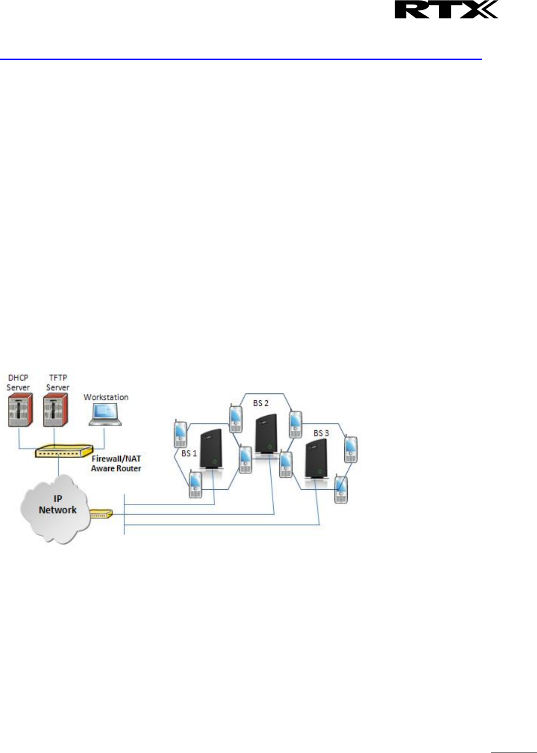
SME VoIP System Guide, Version 2.6
Proprietary and Confidential
Chapter: Firmware Upgrade Procedure
95
8 Firmware Upgrade Procedure
This step-by-step chapter describes how to upgrade or downgrade base station(s) and/or handset(s) /
repeater (s) to the relevant firmware provided by RTX.
8.1 Network Dimensioning
In principle, a number of hardware and software components should be available or be satisfied before
base station/handset update can be possible.
The minimum hardware and software components that are required to be able update via TFTP include the
following (but not limited to):
Handsets
Base stations
TFTP Server (Several Windows and Linux applications are available)
DHCP Server (Several Windows and Linux applications are available)
Workstation (e.g. Normal terminal or PC)
Any standard browser (e.g. Firefox)
Public/Private Network
8.2 TFTP Configuration
This section illustrate TFTP Server configuration using “SolarWinds” vendor TFTP Server. Create the
following relevant folders as shown in the snap shots and choose defaults settings for the remaining
options and save.
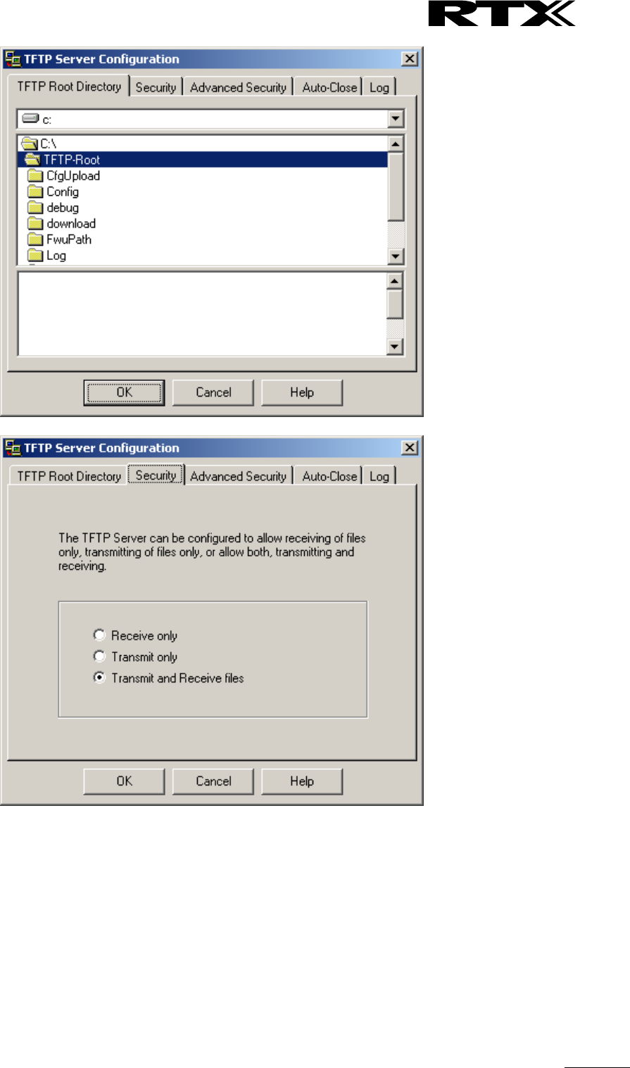
SME VoIP System Guide, Version 2.6
Proprietary and Confidential
Chapter: Firmware Upgrade Procedure
96
NOTE: If TFTP server timeout settings are too short firmware upgrade might not complete. Recommended
time out setting is more than 3 seconds.
8.3 Create Firmware Directories
The admin from the service provider’s side must create the relevant firmware directory in the server where
both old and new firmware(s) can be placed in it. (See the STEP above)
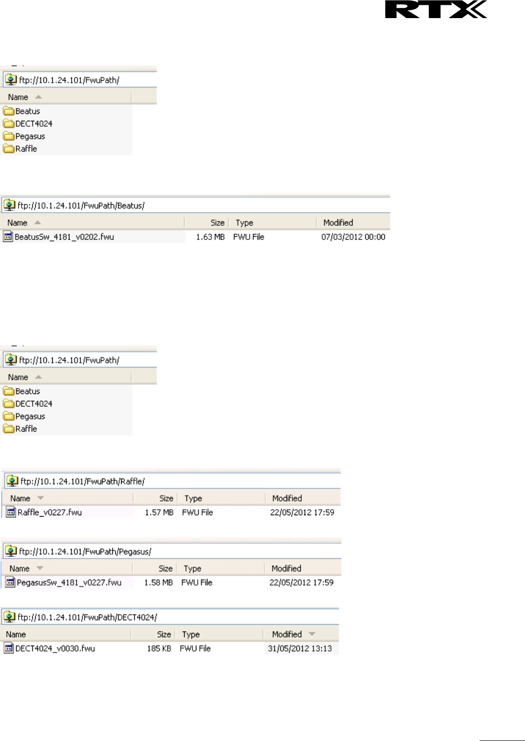
SME VoIP System Guide, Version 2.6
Proprietary and Confidential
Chapter: Firmware Upgrade Procedure
97
8.3.1 Base:
On the TFTP server root, create directory “Beatus”.
Copy Base station firmware to the named directory.
IMPORTANT:
The BeatUs directory name cannot be changed.
8.3.2 Handsets/Repeaters:
On the TFTP server root, create directory “Pegasus” or “Raffle” or “Razor” or “DECT4024” depending on
type.
Copy handset/repeater firmware to the named directory.
IMPORTANT:
The Raffle, Pegasus, DECT4024 directory names cannot be changed.
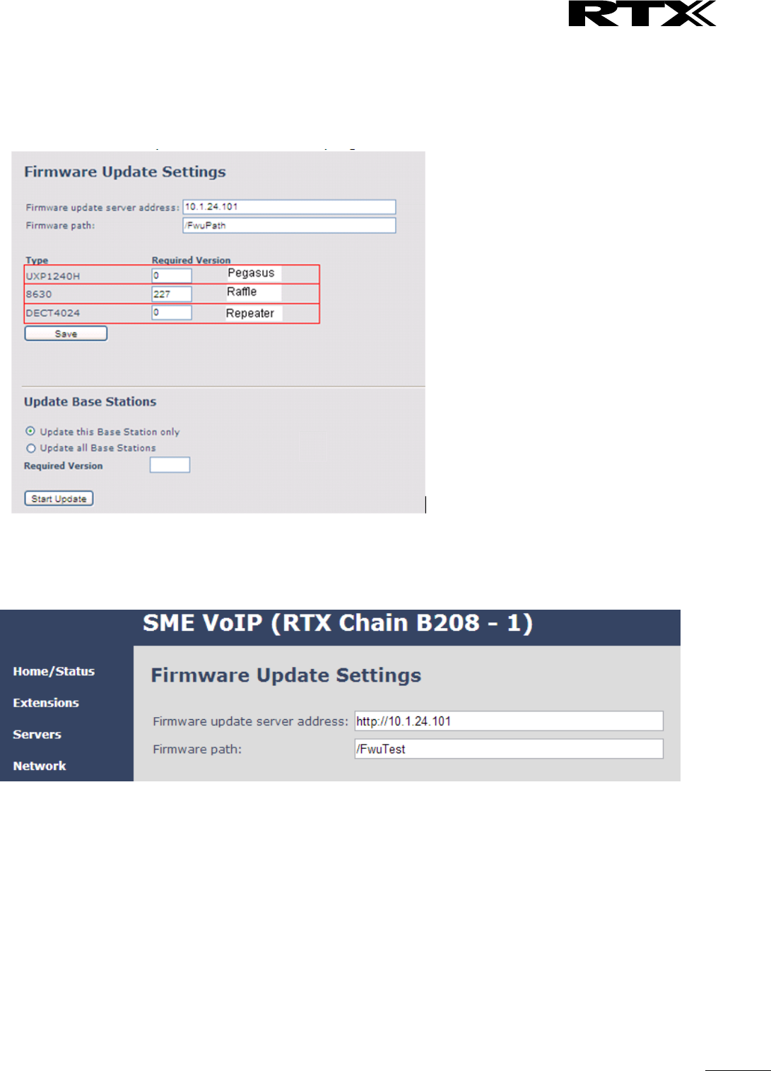
SME VoIP System Guide, Version 2.6
Proprietary and Confidential
Chapter: Firmware Upgrade Procedure
98
8.4 Handset Firmware Update Settings
Scroll down and Click on Firmware Update url link in the SME VoIP Configuration Interface to view the
Firmware Update Settings page.
Type IP address and firmware path followed by save.
For Http download the firmware update server settings must be entered as follows:
8.5 Handset(s) and Repeater Firmware Upgrade
On the Firmware Update Settings page enter the relevant handset/repeater firmware for each type (e.g.
273 for V273) to upgrade or downgrade > press Save button to initialize the process of updating all
handsets.
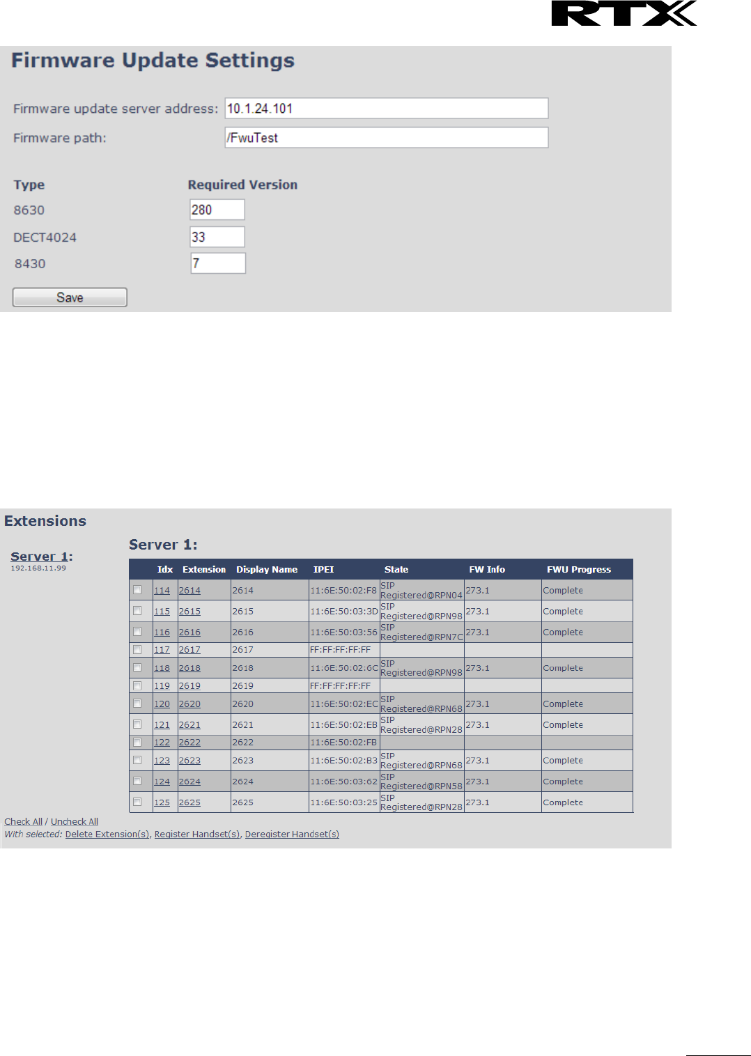
SME VoIP System Guide, Version 2.6
Proprietary and Confidential
Chapter: Firmware Upgrade Procedure
99
NOTE: To disable handset/repeater firmware process type version 0 in the required version field, followed
by the save button. It is recommended to use version 0 after all units are upgraded.
NOTE: For handset TFTP/HTTP download only one handset type can be downloaded at the same time. In
case two handset models are defined for fwu at the same time fwu will fail.
8.5.1 Monitor handset firmware upgrade
Handset firmware upgrade status is monitored on the handset extensions page, right column.
Handset firmware update time from start to complete takes minimum 40 minutes.
8.5.2 Monitor Repeater firmware upgrade
Repeater firmware upgrade status is monitored on the Repeater page, right column.
Repeater firmware upgrade time from start to complete takes minimum 20 minutes.
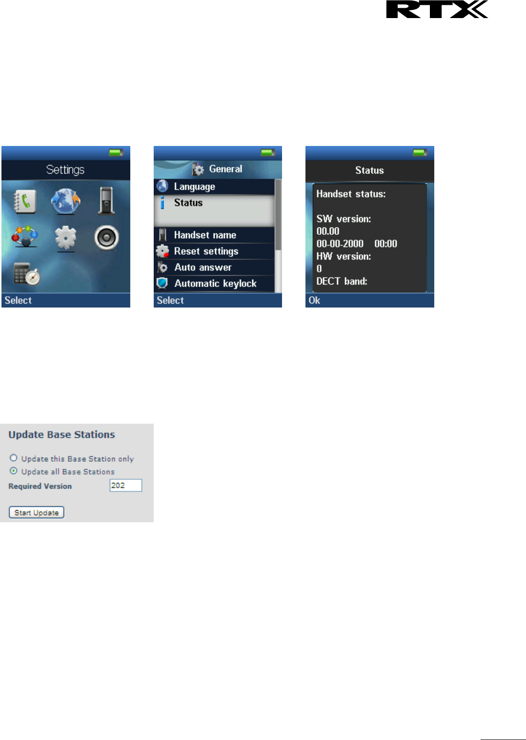
SME VoIP System Guide, Version 2.6
Proprietary and Confidential
Chapter: Firmware Upgrade Procedure
100
8.5.3 Verification of Firmware Upgrade
The firmware upgrade is confirmed by the FWU Progress status in the second and first right column on the
handset extension list or repeater list. The “FWU info” column contains the software version and the “FWU
Progress” column contains the status. In case status is “Complete”, the unit is firmware upgraded.
Alternatively the handset firmware can be verified from the Handset Menu by navigate to Settings > Scroll
down to Status this will list information regarding Base station and Handset firmware versions.
8.6 Base Station(s) Firmware Upgrade
On the Firmware Update Settings page > scroll down to the Update Gateways section > Enter the relevant
firmware version of the base station to upgrade or to downgrade. Enter 202 for base version V0202.
For multi cell upgrade remember to check “update all Base Stations”.
Efter entering required version choose Start update button > select OK button from the dialog window to
start the update/downgrade procedure.
The relevant base station(s) will automatically reboot and retrieve the firmware specified from the server
and update itself accordingly.
The base firmware update behaviour is: Base will fetch the fwu file for approximately 3 minutes, then
reboot and start flashing the LED - indicated by LED fast flashing for approximately 3 minutes and reboots
in new version.
Note: All on-going voice calls are dropped from the base station(s) immediately the firmware update
procedure starts.
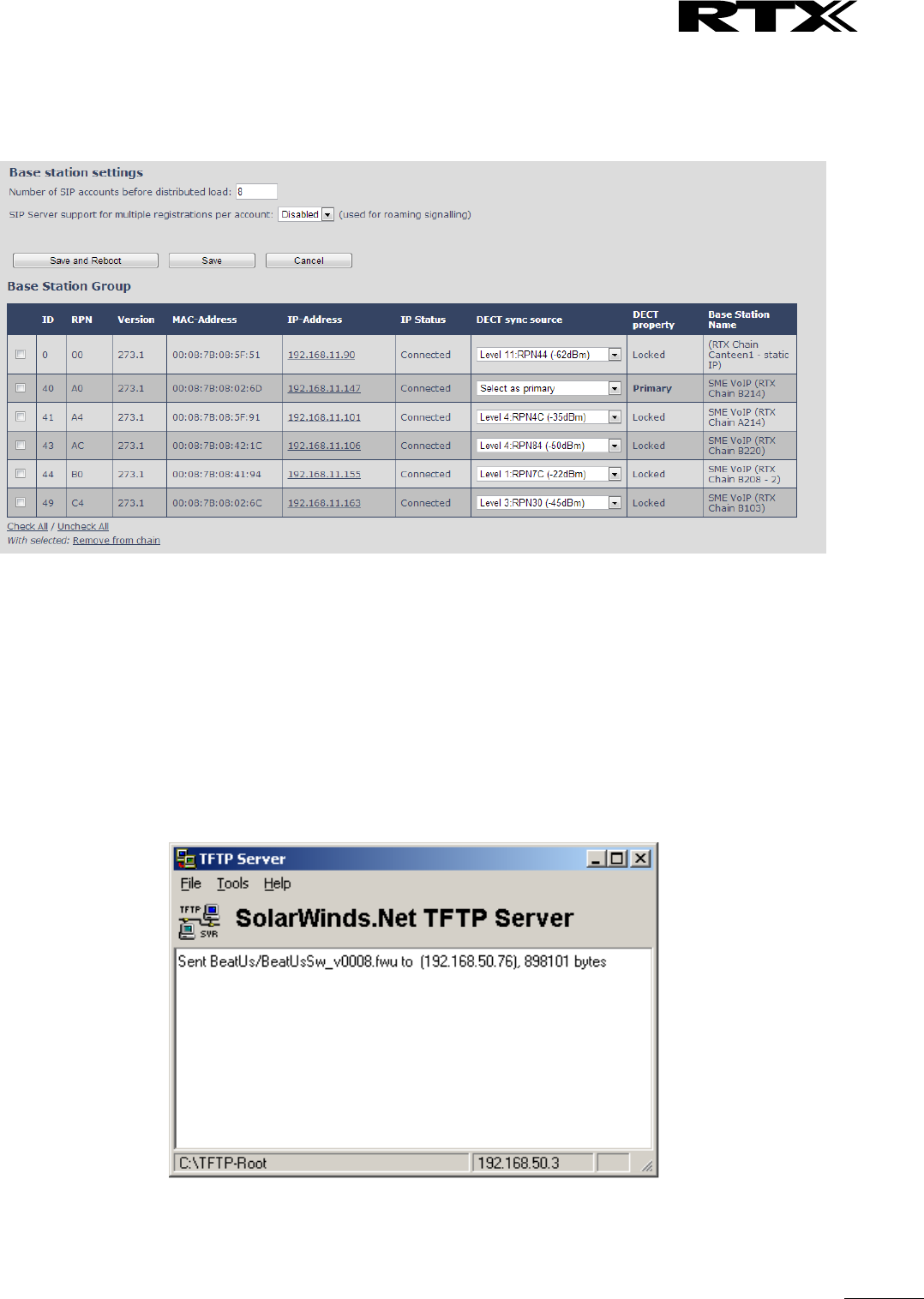
SME VoIP System Guide, Version 2.6
Proprietary and Confidential
Chapter: Firmware Upgrade Procedure
101
8.6.1 Base firmware confirmation
Base station firmware version status in a multicell environment can be seen in the multicell base station
group overview page, column 4.
8.6.2 Verification of Firmware Upgrade
Syslog information when Management Syslog level is set to “Debug”
[ FWU Downloading File tftp://10.1.24.101/FwuPath/Beatus/BeatusSw_4181_v0202.fwu]
[ Base FWU started]
[ Base FWU ended with exit code 2101 (NE_FILE_TRANSFER_EOF): End of file]
The log window of the TFTP server:
SME VoIP System Guide, Version 2.6
Proprietary and Confidential
Chapter: Functionality Overview
102
9 Functionality Overview
So far we have setup our SME VoIP system. Next, in this chapter we list what features and functionalities
are available in the system. The SME VOIP system supports all traditional and advanced features of most
telephony networks. In addition, 3rd party components handle features like voice mail, call forward,
conference calls, etc. A brief description of SME VOIP network functionalities are:
Outgoing/incoming voice call management: The SME VOIP system can provide multiple priority user
classes. Further, up to 3 repeaters can be linked to a Base-station.
Internal handover: User locations are reported to SIP Server in order to provide differentiated services
and tariff management. Within a DECT traffic area, established calls can seamlessly be handover
between Base-stations using connection handover procedures.
Security: The RTX SME VOIP system also supports robust security functionalities for Base-stations.
Most security
2
functionality is intrinsically woven into the SME VOIP network structure so that network
connections can be encrypted and terminal authentication can be performed.
9.1 Gateway Interface
Connector interfaces
Power
Connector: Ethernet PoE (Ethernet adaptor for normal power)
IEEE 802.3: Power class 2 (3.84 – 6.49W)
LAN Interface
Standard : 10BASE-T(IEEE 802.3 100Mbps)
Connector: RJ45 8/8
Internet Protocol:
IPv4
IPv6
Keys
1 x Reset key
LED indicator
One Status LED (multicolor, red, green, orange)
RF
Frequency Bands
1880 – 1900 MHz (EMEA)
1910 – 1930 MHz (Latam)
1920 – 1930 MHz (USA)
This is software settings and to be set when it is packed in factory.
Output Power
<250 mW (for USA < 140mW)
Antenna
Two antennas for diversity
Software update
Downloadable
Remote firmware update HTTPS/TFTP
9.2 Detail Feature List
CODECs
G.711 PCM A-law & U-law
Uncompressed voice
Silence suppression ( No)
G.722
Allows HD sound for the handset
G.726
ADPCM, 32 Kbps
G.729
A
G.729.1 (ehem. G.729 EV)
2
With active security with authentication 4 channels is supported

SME VoIP System Guide, Version 2.6
Proprietary and Confidential
Chapter: Functionality Overview
103
Note: Only with additional module, this is an extra option that requires a board connector
mounted in Gateway. Per default not mounted.
SIP
RFC2327
SDP: Session Description Protocol
RFC2396
Uniform Resource Identifiers (URI): Generic Syntax
RFC2833
In-Band DTMF/Out of band DTMF support
RFC2976
The SIP INFO method
RFC3261
SIP 2.0
RFC3262
Reliability of Provisional Responses in the Session Initiation Protocol (PRACK)
RFC3263
Locating SIP Servers (DNS SRV, redundant server support)
RFC3264
Offer/Answer Model with SDP
RFC3265
Specific Event Notification
RFC3311
The Session Initiation Protocol UPDATE Method
RFC3325
P-Asserted Identity
RFC3326
The Reason Header Field for the Session Initiation Protocol (SIP)
RFC3489
STUN
RFC3515
REFER: Call Transfer
RFC3550
RTP: A Transport Protocol for Real-Time Application
RFC3581
Rport
RFC3842
Message Waiting Indication
RFC3891
Replace header support
RFC3892
The Session Initiation Protocol (SIP) Referred-By Mechanism
RFC3960
Early Media and Ringing Tone Generation in the Session Initiation Protocol (SIP)
RFC4475
Session Initiation Protocol (SIP) Torture Test Messages
SIPS
SRTP
Will limit number of active calls pr. base when enabled.
Web server
Embedded web server HTTP
Other features
Quality of service
Type of Service (ToS) including DiffServ Tagging, and QoS per IEEE 802.1p/q
IP Quality
Warning – Network outage, VoIP service outage
Adaptive Jitter Buffer support
Automatic DST
Tone Scheme
Country Depend Tone Scheme
Ethernet features
Speed duplex
10 & 100 duplex
VLAN
VLAN (802.1p/q)
DHCP Support
Static IP
TLS 1.0
For secure connections (AES 128)
TFTP
For configuration download.
HTTP
For configuration download.
HTTPS
For secure configuration download.
TCP/IP/UDP
SNTP
For internet clock synchronization
Quality of service
Type of Service (ToS) including DiffServ Tagging, and QoS per IEEE 802.1p/q
DHCP option
66
DNS srv
DECT
DECT CAP
Connectionless handover, enhanced location registration
CAT-IQ v1.0
Wideband Speech
General Telephony
Handset Support
10 simultaneous handsets supported (single cell)
(10 call / single cell and 8 call/Multi cell)
Total 1000 simultaneous call supported / system

SME VoIP System Guide, Version 2.6
Proprietary and Confidential
Chapter: Functionality Overview
104
VoIP Accounts
30 VoIP accounts per base – (maximum 254 bases per installation)
Total 1000 VoIP accounts / system
Maximum 1000 handsets per installation
Simultaneous Calls
4 Wideband calls (g.722) or 10 single cell, 8 multi cell narrowband calls (PCMA, PCMU,
G.726) or mixed wideband and narrowband.
Call features
Codec Negotiation
Codec Switching
Missed call notification
Voice message waiting notification
Date and Time synchronization
Parallel calls
Common parallel call procedures
Call transfer unannounced
Call transfer announced
Conference
Call Waiting
Calling line identity restriction
Outgoing call
Call Toggle
Incoming call
Line identification
Multiple Lines
Multiple calls
Call identification
Calling Name Identification Presentation (CNIP)
Calling Line Identification Presentation (CLIP)
Call Hold
List of registered handsets
Call log
50 mixed between Incoming, outgoing, missed calls
Phone Book
Common Phonebook with up to 3000 entries (Import via csv format)
Common Phonebook LDAP V2.0
Local Phonebook (100 entries 8630 and 50 entries 8430)
DND
Do Not Disturb
Call Forward
All
No Answer
Busy
Individual Speed dial
Programmable Function keys

SME VoIP System Guide, Version 2.6
Proprietary and Confidential
Chapter: Appendix A: Basic Network Server(s) Configuration
105
Appendix
10 Appendix A: Basic Network Server(s) Configuration
In this chapter we describe how to setup the various server elements in the system.
10.1 Server setup
In the SME network, the server environment is installed as a centralized system.
The main server types hosted on the network include SIP, DNS/DHCP and HTTP/TFTP Servers. These servers
can be hosted both in one or multiple windows and/or Linux Server environment.
Management servers are normally installed to monitor and manage the network in detail. Each Base-
station status can be checked. Each Repeater and each Subscriber Terminal can be monitored over the air
from a centralized location.
Further, new software can be uploaded to all system elements from the centralized location (typically a
TFTP server) on an individual basis. This includes Subscriber Handsets where the latest software is
downloaded over the air.
10.2 Requirements
Regardless of whether or not you will be installing a centrally provisioned system, you must perform basic
TCP/IP network setup, such as IP address and subnet mask configuration, to get your organization’s phones
up and running.
10.3 DNS Server Installation/Setup
Name server is a name server service installed in a server for mapping or resolution of humanly memorable
domain names and hostnames into the corresponding numeric Internet Protocol (IP) addresses.
The customer should refer to the platform vendor either windows or Linux vendor for detail step-by-step
guide on how to install and configure Domain Name System for internet access. In this section, we briefly
describe hints on how to setup DNS behind NAT or Firewall.
10.3.1.1 Hints on how to Configure DNS behind a Firewall/NAT
Proxy and Network Address Translation (NAT) devices can restrict access to ports. Set the DNS to use UDP
port 53 and TCP port 53. For windows Servers, set the RCP option on the DNS Service Management console
and configure the RCP to use port 135.
These settings should be enough to resolve some of potential issues that may occur when you configure
DNS and firewalls/NAT.
10.4 DHCP Server Setup
A DHCP Server allows diskless clients to connect to a network and automatically obtain an IP address. This
server is capable of supplying each network client with an IP address, subnet mask, default gateway, an IP
address for a WINS server, and an IP address for a DNS server. This is very often used in enterprise
networks to reduce configuration efforts. All IP addresses of all computers/routers/bases are stored in a
database that resides on a server machine.
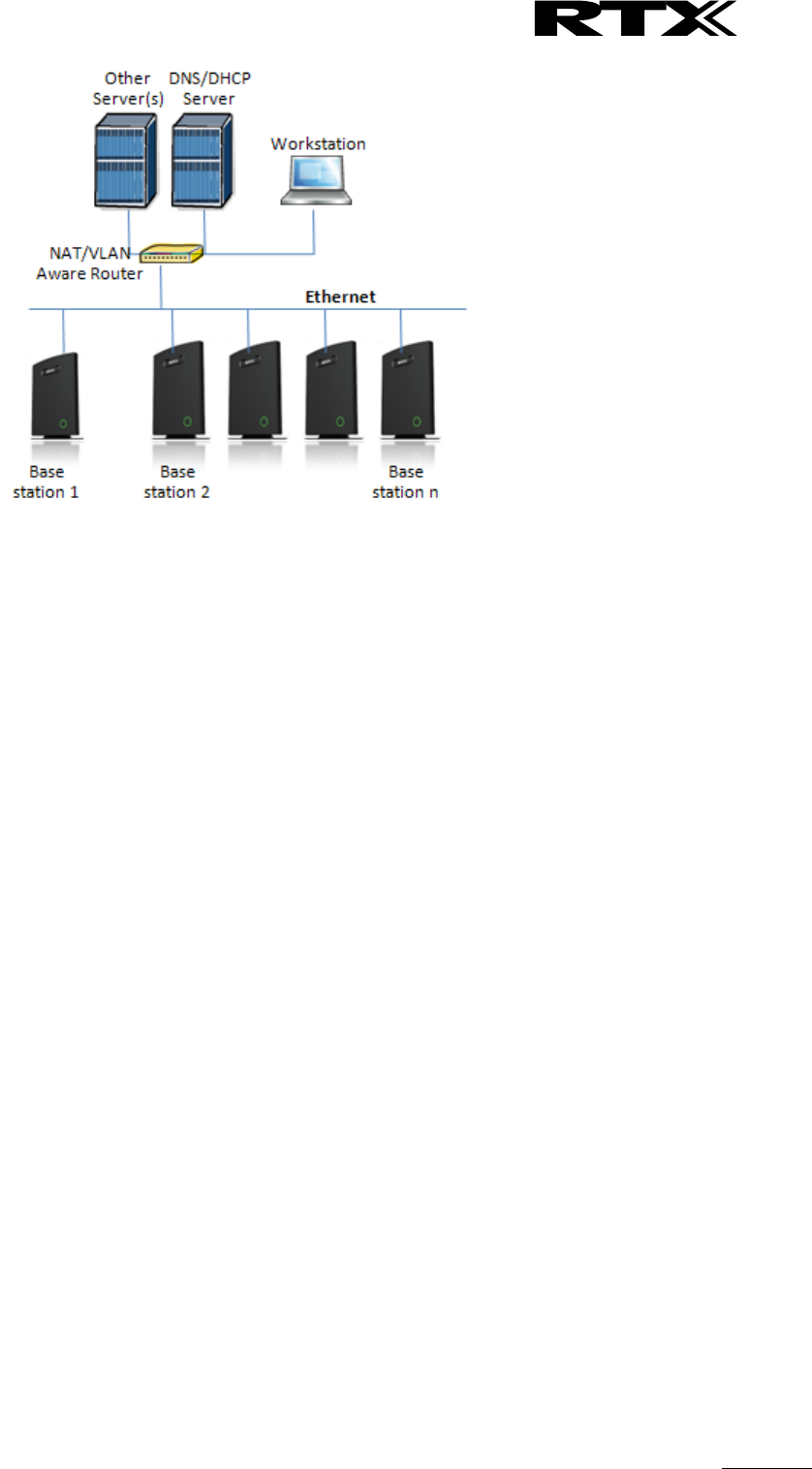
SME VoIP System Guide, Version 2.6
Proprietary and Confidential
Chapter: Appendix A: Basic Network Server(s) Configuration
106
The network administrator should contact the relevant vendors for detail information or step-by-step
procedure on how to install and setup DHCP process or service on windows/Linux servers. In this section,
we will provide some hints of how to resolve potential problems to be encountered you setup DHCP
Servers.
10.4.1 Hint: Getting DHCP Server to Work
Windows Server:
1) Clients are unable to obtain an IP address
If a DHCP client does not have a configured IP address; it generally means that the client has not been
able to contact a DHCP server. This is either because of a network problem or because the DHCP server
is unavailable. If the DHCP server has started and other clients have been able to obtain a valid address,
verify that the client has a valid network connection and that all related client hardware devices
(including cables and network adapters) are working properly.
2) The DHCP server is unavailable
When a DHCP server does not provide leased addresses to clients, it is often because the DHCP service
has failed to start. If this is the case, the server may not have been authorized to operate on the
network. If you were previously able to start the DHCP service, but it has since stopped, use Event
Viewer to check the system log for any entries that may explain the cause.
Next, restart the DHCP service, click Start, click Run, type cmd, and then press ENTER. Type
net start dhcpserver,
and then press ENTER.
Linux Platform:
Troubleshooting DHCP, check the following:
1) Incorrect settings in the /etc/dhcpd.conf file such as not defining the networks for which the DHCP
server is responsible;
2) NAT/Firewall rules that block the DHCP bootp protocol on UDP ports 67 and 68;
3) Routers failing to forward the bootp packets to the DHCP server when the clients reside on a separate
network. Always check your /var/logs/messages file for dhcpd errors.
4) Finally restart the dhcpd service daemon
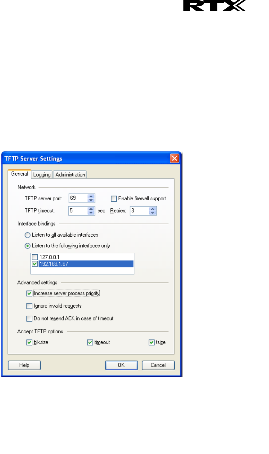
SME VoIP System Guide, Version 2.6
Proprietary and Confidential
Chapter: Appendix A: Basic Network Server(s) Configuration
107
10.5 TFTP Server Setup
There are several TFTP servers in the market place; in this section we describe how to setup a commonly
used TFTP Server.
10.5.1 TFTP Server Settings
The administrator must configure basic parameters of the TFTP application:
Specify UDP 69 port – for TFTP incoming requests and TCP 12000 – for remote management of the
server. For file transmission the server opens UDP ports with random numbers. In case the option
Enable NAT or firewall support is activated on the server, the server uses the same port for files
transmission and listening to the TFTP incoming requests (UDP 69 port on default).
Specify the interface bindings, TFTP root directory, port which the TFTP Server will listen, timeout and
number of retries, and TFTP options supported by the server.
Configure the relevant TFTP virtual folder in the server. The TFTP virtual folder is the file folder,
visible for TFTP clients under a certain name. You can set security settings separately for every
virtual TFTP folder. Next, set rights to access TFTP folders according to the relevant clients.
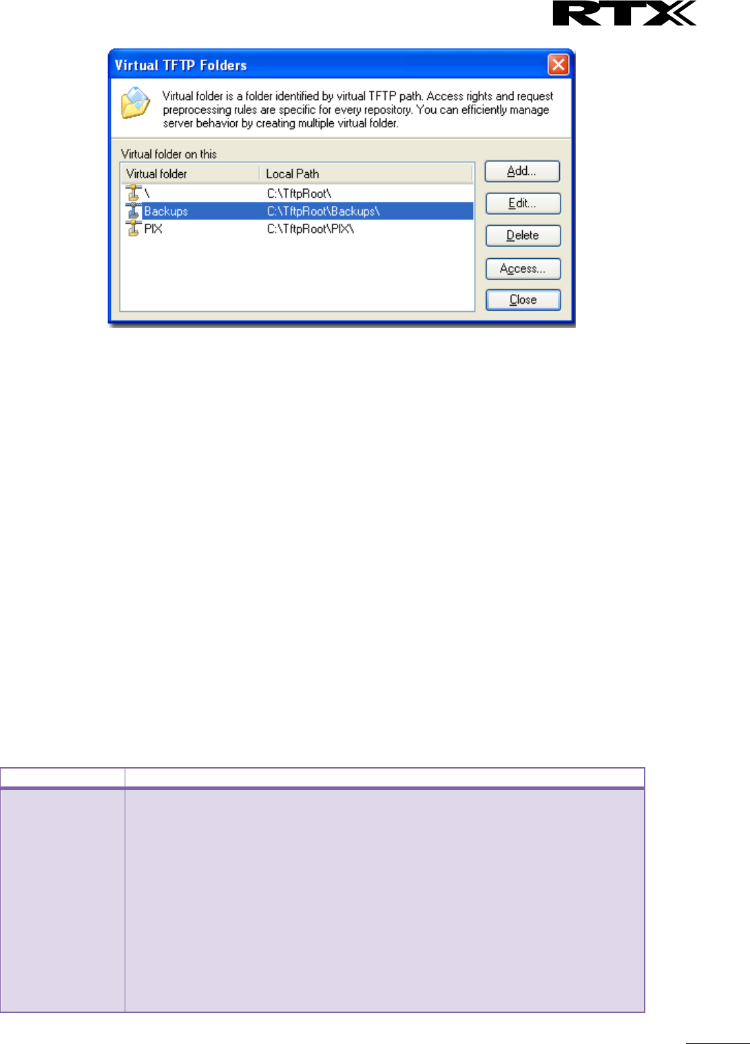
SME VoIP System Guide, Version 2.6
Proprietary and Confidential
Chapter: Appendix A: Basic Network Server(s) Configuration
108
10.6 SIP Server Setup
SIP server is one of the main components of an SME network, dealing with the setup of all SIP calls in the
network. A SIP server is also referred to as a SIP Proxy or a Registrar.
Although the SIP server is the most important part of the SIP based phone system, some servers only
handles call setup and call tear down. It does not actually transmit or receive any audio. This is done by the
media server in RTP.
The RTX SME family of network phones are fully interoperable with the most of SIP Server applications.
There are many off-the-shelf vendor and open source SIP servers. In this section, we will briefly explain
settings required to take full advantage of FreePBX SIP Server feature set. The settings are similar for other
SIP servers.
10.6.1 FreePBX SIP Server
FreePBX is an easy to use GUI (graphical user interface) that controls and manages Asterisk, which the most
popular open source telephony engine software.
The administrator should refer to the relevant detail step-by-step procedure of how to install FreePBX SIP
server. This section briefly describes SIP Server setup parameters.
1) SIP Server Setup
Settings
Description
NAT
This option determines the settings for users connecting to an asterisk server.
Possible values: Yes, No, Never, Route
NAT=route
Asterisk will send the audio to the port and IP where it’s receiving the audio from.
Instead of relying on the addresses in the SIP and SDP messages.
This will only work if the phone behind NAT send and receive audio on the same
port and if they send and receive the signalling on the same port. (The signalling
port does not have to be the same as the RTP audio port).
NAT=No
Asterisk will add an RPORT to the via header of the SIP messages
NAT=never
This will cause asterisk not to add an RPORT in the VIA line of the sip invite
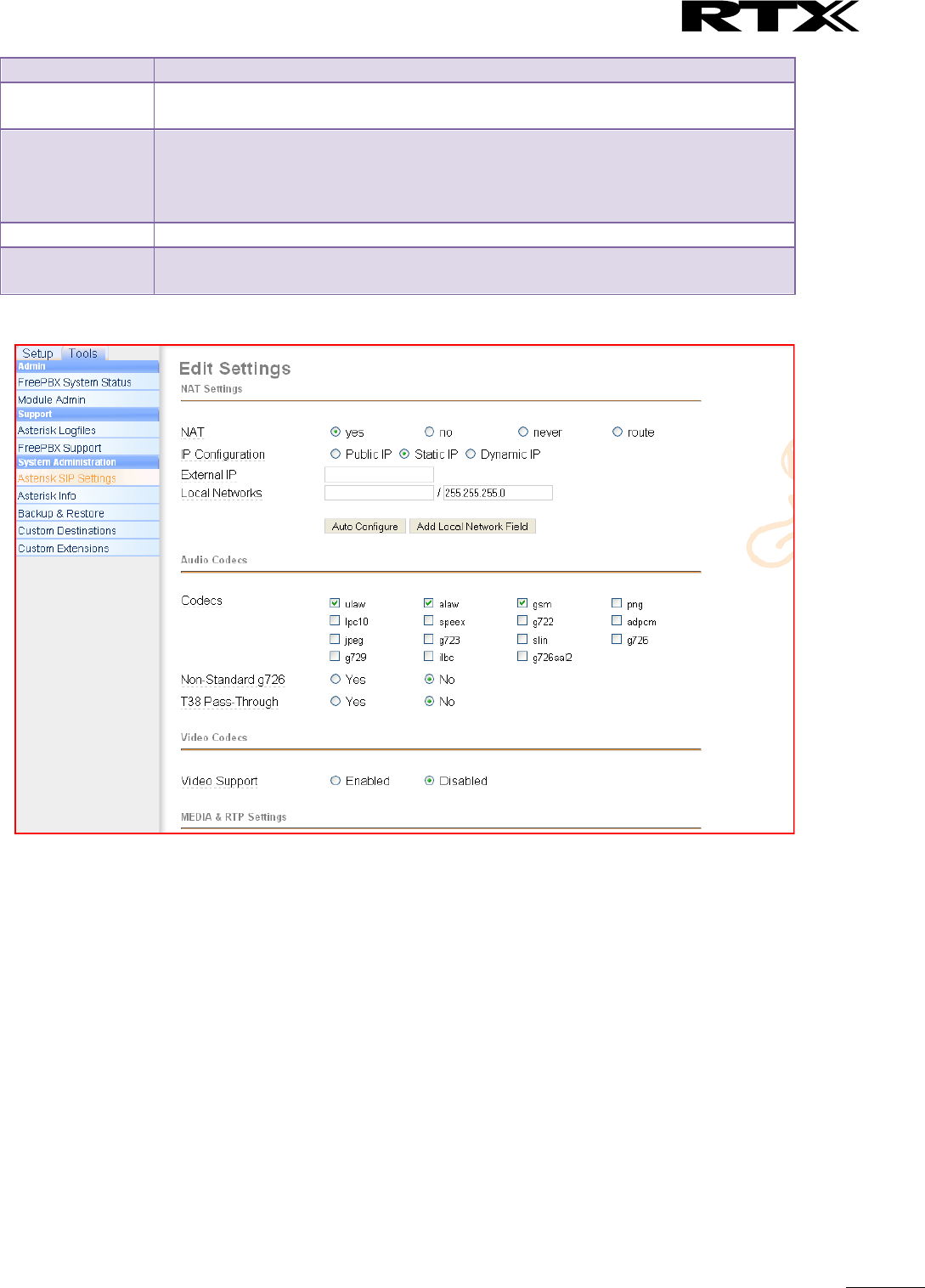
SME VoIP System Guide, Version 2.6
Proprietary and Confidential
Chapter: Appendix A: Basic Network Server(s) Configuration
109
header
Other NAT
Settings
Choose the relevant option or enter the settings in IP configuration, External IP,
Local Network.
Codecs
Some SIP Servers supports dynamic codec support. Codecs are algorithm used to
compress or decompress speech or audio signals. The user should select the
relevant Codecs and other speech compression techniques whose traffic will be
routed to the SME network.
Video Codecs
The user should enable this option if SME network supports video telephony.
Media & RTP
Settings
This option should be enabled to provide for deliver media streams (e.g., audio
and video) or out-of-band events signalling (DTMF in separate payload type).
2) Extensions
This feature allows administrators create handset profiles in the SME network. In other words, Extensions
describes the Dial plan for the PBX SIP system. Enter the relevant parameters
SME VoIP System Guide, Version 2.6
Proprietary and Confidential
Chapter: Appendix A: Basic Network Server(s) Configuration
110
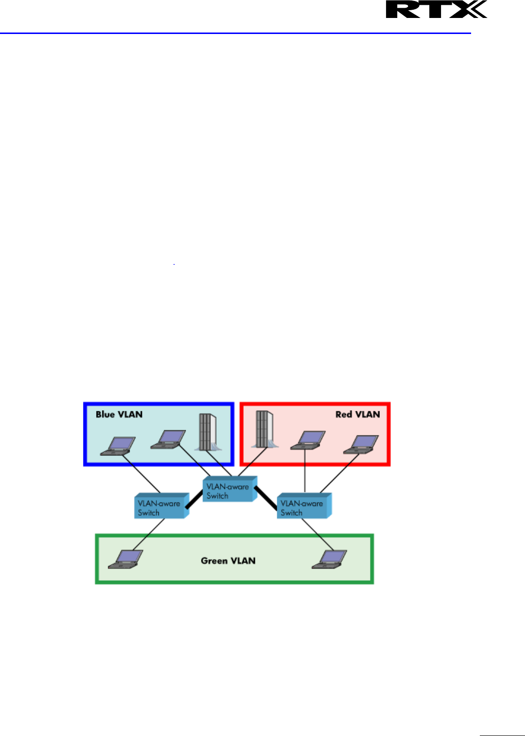
SME VoIP System Guide, Version 2.6
Proprietary and Confidential
Chapter: Appendix B: Using Base with VLAN Network
111
11 Appendix B: Using Base with VLAN Network
In this chapter we describe how to setup a typical VLAN in the network.
11.1 Introduction
In this chapter, we describe how to setup VLAN to typical network. There are three main stages involved in
this procedure:
1) Configure a VLAN Aware Switch to a specific (un)tagged VLAN ID, so the SME system can process
untagged frames forwarded to it.
2) Setup the Time Server (NTP Server) and other relevant network servers.
3) Configure the HTTP server in relevant Base stations to access the features in the PBX or SME
system.
VLAN allows administrators to separate logical network connectivity from physical connectivity
analogous to traditional LAN which is limited by its physical connectivity. Normally, users in a LAN
belong to a single broadcast domain and communicate with each other at the Data Link Layer or
“Layer 2”. LANs are segmented into smaller units for each IP subnets and here communication
between subnets is possible at the Network Layer or “Layer 3”, using IP routers.
A VLAN can be described as a single physical network that can be logically divided into discrete
LANs that can operate independently of each other.
An Illustration of using VLANs to create independent broadcast domains across switches is shown
below:
The figure above highlights several key differences between traditional LANs and VLANs.
All switches are interconnected to each other. However, there are three different VLANs or
broadcast domains on the network. Physical isolation is not required to define broadcast
domains. If the figure was a traditional LAN without VLAN-aware switches, all stations
would belong to one broadcast domain.
All switch ports can communicate with one another at the Data Link Layer, if they become
members of the same VLAN.

SME VoIP System Guide, Version 2.6
Proprietary and Confidential
Chapter: Appendix B: Using Base with VLAN Network
112
The physical location of an end station does not define its LAN boundary.
1. An end station can be physically moved from one switch port to another without losing
its “view of the network”. That is, the set of stations it can communicate with at the
Data Link Layer remains the same, provided that its VLAN membership is also migrated
from port to port.
2. By reconfiguring the VLAN membership of the switch port an end station is attached to,
you can change the network view of the end station easily, without requiring a physical
move from port to port.
11.2 Backbone/ VLAN Aware Switches
To implement a VLAN in your network, you must use VLAN-aware switches.
Before we continue, let consider two rules to remember regarding the functioning of a regular
LAN switch:
1. When the switch receives a broadcast or multicast frame from a port, it floods (or
broadcasts) the frame to all other ports on the switch.
2. When the switch receives a unicast frame, it forwards it only to the port to which it is
addressed.
A VLAN-aware switch changes the above two rules as follows:
1. When the switch receives a broadcast or multicast frame from a port, it floods the frame to
only those ports that belong to the same VLAN as the frame.
2. When a switch receives a unicast frame, it forwards it to the port to which it is addressed,
only if the port belongs to the same VLAN as the frame.
3. A unique number called the VLAN ID identifies each VLAN.
Which VLAN Does a Frame Belong To?
The previous section notes that a frame can belong to a VLAN. The next question is—how is this
association made?
A VLAN-aware switch can make the association based on various attributes of the type of
frame, destination of MAC address, IP address, TCP port, Network Layer protocol, and so
on.
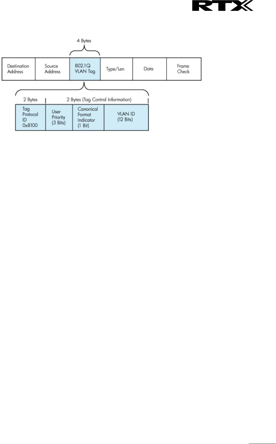
SME VoIP System Guide, Version 2.6
Proprietary and Confidential
Chapter: Appendix B: Using Base with VLAN Network
113
An illustration of IEEE 802.1Q VLAN tag in Ethernet frame is as follows:
11.3 How VLAN Switch Work: VLAN Tagging
VLAN functionality can be implemented via explicit frame tagging by switches and end stations.
Network switches and end stations that know about VLANs are said to be VLAN aware. Network
switches and end stations that can interpret VLAN tags are said to be VLAN tag aware. VLAN-tag-
aware switches and end stations add VLAN tags to standard Ethernet frames–a process called
explicit tagging. In explicit tagging, the end station or switch determines the VLAN membership of
a frame and inserts a VLAN tag in the frame header (see figure above for VLAN tagging), so that
downstream link partners can examine just the tag to determine the VLAN membership.
11.4 Implementation Cases
Common types of usage scenarios for VLANs on typical VLAN switches: port-based VLANs,
protocol-based VLANs, and IP subnet-based VLANs. Before figuring out which usage scenario suits
your needs, you must understand what each type of usage scenario implies.
Port-based VLAN: All frames transmitted by a NIC are tagged using only one VLAN ID. The
NIC does not transmit or receive any untagged frames.
All protocols and applications use this virtual interface’s virtual PPA to transmit data traffic.
Therefore all frames transmitted by that NIC port are tagged with the VLAN ID of that
Virtual Interface.
Protocol-based VLAN: The NIC assigns a unique VLAN ID for each Layer 3 protocol (such as
IPv4, IPv6, IPX, and so on). Therefore, the VLAN ID of outbound frames is different for each
protocol. An inbound frame is dropped if the protocol and VLAN ID do not match.
IP subnet-based VLAN: The NIC assigns a unique VLAN ID for each IP subnet it belongs to.
Therefore, the VLAN ID of outbound frames is different for different destination subnets.
An inbound frame is dropped if the IP subnet and VLAN ID do not match.

SME VoIP System Guide, Version 2.6
Proprietary and Confidential
Chapter: Appendix B: Using Base with VLAN Network
114
11.5 Base station Setup
After the admin have setup the Backbone switch, next is to configure the Base stations via HTTP interface.
STEP 1 Connect the Base station to a private network via standard Ethernet cable (CAT-5).
STEP 2 Use one of the two methods to find the base IP
STEP 3 On the Login page, enter your authenticating credentials (the username and password is
admin by default unless it is changed). Click OK button.
STEP 4 Once you have authenticated, the browser will display front end of the SME Configuration
Interface. The front end will show relevant information of the base station.
STEP 5 Create the relevant SIP server information in the system. Each service provider/customer
should refer SIP server vendor on how to setup SIP servers.
11.6 Configure Time Server
STEP 6 Navigate to the Time settings and configure it. Scroll on the left column and click on Time url
link to Open the Time Settings Page. Enter the relevant parameters on this page and press the Save
button.
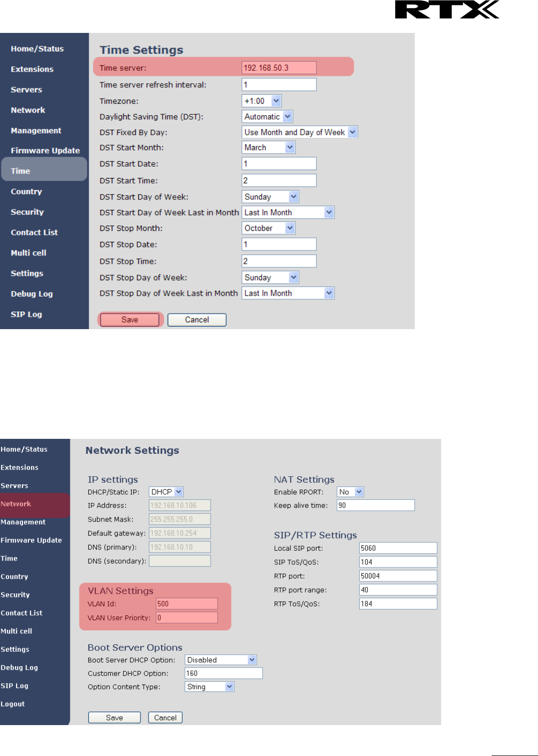
SME VoIP System Guide, Version 2.6
Proprietary and Confidential
Chapter: Appendix B: Using Base with VLAN Network
115
11.7 VLAN Setup: Base station
STEP 7 Navigate to the Network url > On the network page enter the relevant settings in the VLAN
section > VLAN Id should be the same as those configured into the backbone.

SME VoIP System Guide, Version 2.6
Proprietary and Confidential
Chapter: Appendix C: SME VoIP Network Planning/Optimization
116
12 Appendix C: SME VoIP Network Planning/Optimization
In this chapter, we describe SME VoIP radio network planning techniques including dimensioning, detailed
capacity and coverage planning, and network optimisation.
12.1 Network Requirements
Network requirement is essential to determine elements necessary to achieve the overall expectations of
the customer. Typical network requirements includes (but not limited to):
The geographical area to be covered
The type or architecture of building and/or topology, etc.
The estimated traffic on each zone or region or building
The blocking criteria in each traffic area.
The relevant quality targets expected to be achieved
12.2 Deployment Considerations
The following radio considerations must be examined before deploying a SME VoIP System. These includes
(but not limited to):
Building Penetration:
When a signal strikes a building it is diffracted or absorbed; therefore to some extend the signal is reduced.
The amount of absorption is dependent of the kind of building and its environment, the amount of solid
structure. This is an important consideration in coverage planning.
Interference Sources:
Signals to receiving antenna can be weakened by virtue of interference from other signals. These signals
may be from the same network or other man-made objects. Interference sources must be identified and
avoided or minimized.
12.3 Site Planning
12.3.1 Location Probability
The quality of coverage is determined by location probability. Please see the How to Deploy SME VOIP
System manual for more information.
12.3.2 Handover Mechanics/Planning
Handsets should seamlessly move between coverage areas. In other words, handset should be able to
move in a multi-cell setup of base stations and/or repeaters from one base station to another without
terminating or causing hindrance while receiving continuous service and maintaining call-sessions in
progress.
For efficient handover of conversations between Base stations in multi-cell setup, deploy Base stations with
wide overlap between them (i.e., plan for some areas to be covered by more than one Base station).
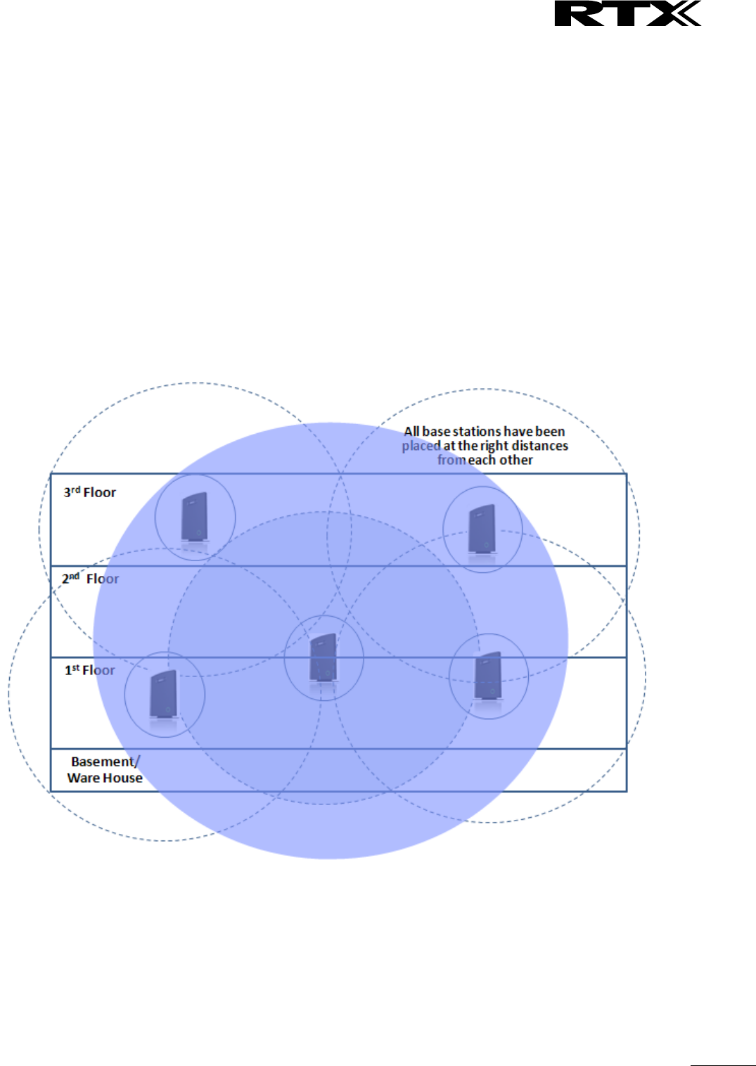
SME VoIP System Guide, Version 2.6
Proprietary and Confidential
Chapter: Appendix C: SME VoIP Network Planning/Optimization
117
Overlaps are necessary to maintain seamless handover and to establish synchronization chains. A good
example may be a cafeteria during lunch hour where temporary concentrations of handsets may occur. The
overlap carries the excess call load to adjacent Base stations to provide uninterrupted services to
subscribers.
12.4 Cell Coverage / Capacity Planning
12.4.1 Cell Coverage
Due to the unexpected nature of RF propagation in an indoor environment, an actual on-site test must be
performed before the deploying and/or installing core network elements. An extensive guide to effective
RF coverage planning is outside the scope of this document. This should be noted:
The Base stations provides typical RF coverage of up to 50 meters/164 feet in a typical indoor office
environment and up 300 meters/984 feet in an open area (line-of-sight-LOS), extending in all directions
from the Base stations (i.e. Omni directional). The exact coverage range depends on the building
architecture, wall material and surroundings. The figure below show the correct installation of base stations
spaced at the recommended distances from each other:
Typically, installations such as office buildings, hotels and hospitals should be equipped with both base
stations and repeaters on several floors to create uniform and complete radio coverage.
Open areas can be covered with a sparse network of base stations. In such deployments, the base stations
and/or repeaters cover an extended range due to the extended line-of-sight radio propagation capability
The figure below shows an example of an installation where base stations are not spaced at the right
distances:
SME VoIP System Guide, Version 2.6
Proprietary and Confidential
Chapter: Appendix C: SME VoIP Network Planning/Optimization
118
12.4.2 Capacity Planning
This is where the Network provider estimates how many calls will be initiated in a typical window/time
frame and how many users will be initiating them.
Another aspect of capacity planning should address the user growth pattern of a typical SME VoIP network.
How many users will be using this network in for example two years window, etc. Based on these
estimations, the network dimensioning can be planned orderly bearing in mind the SME capacity.
12.5 Network Dimensioning
After the network requirements are clearly defined, the number of users that are expected to use the
network must be estimated. Based on that, you should estimate and identify the number and type of
equipment required in order to cater for the capacity, coverage and quality requirements. The more
accurate the dimensioning, the more efficient the network rollout.
Handsets/SIP End-Nodes:
In a typical setup, the system can support up to 1000 handsets depending on the configuration.
Base stations/Repeaters:
The system can easily scale up to 50 base stations. Depending on the network setup, coverage can be
extended by up to 3 repeaters pr. base station. The planner should bear in mind that base stations can
support 10 simultaneously call sessions while repeaters can support 5 call sessions.

SME VoIP System Guide, Version 2.6
Proprietary and Confidential
Chapter: Appendix C: SME VoIP Network Planning/Optimization
119
Core Network Equipment:
This equipment is at the premises of the service operator or data centre. Depending on the network
requirements the following devices should be available:
VLAN/NAT aware router(s), Session Border Controller, DHCP/TFTP/FTP Servers, STUN Server, Media Server,
Access Gateway, SIP Server, etc.
12.6 Environmental Considerations
In this section, we enumerate some environmental conditions that need to be considered prior to planning,
deployment and optimisation of the SME network. The considerations are as follows:
• Ensure that the installation area is clean and dry.
• Ensure that the floor of the installation area is finished with linoleum, vinyl, ceramic, wooden flooring,
computer floor tiles, or polished sealed concrete.
• Ensure that the ceiling of the installation area is finished or treated to prevent particle discharge.
• Ensure that the installation area is well lit, and that the light source is uniformly diffused without
shadows. Adequate lighting should provide a comfortable reading level and allow the identification of
wire insulator colours without undue eye fatigue. Lighting should be comparable to an office work
environment, with a minimum level of 21 meter/68.9 feet at each work surface. As a rule of thumb, in a
room with a 2.5 meters/8.2 feet ceiling, one 1.2 meters/4 feet fluorescent tube provides sufficient
illumination for 1.9-2.4 square meters/20.5-25.9 square feet.
• Ensure that ventilation of the installation area is capable of maintaining an ambient temperature of 0-
40°C/32-104°F, and a relative humidity of 20-80% non-condensing, while the system is operating. The
maximum power rating of a base station under full load should not exceed 315W/1070 BTU/Hr. These
figures are for each cabinet only, and do not take into account heat generated by other equipment. In
particular, charging fully-discharged batteries may generate a considerable amount of heat, depending
on battery capacity and rate of charge. Refer to the equipment manufacturer data for more
information.
• Ensure that the installation area is free of caustic or corrosive liquids, substances, or materials. If
batteries will be installed as part of the system, ensure that adequate precautions are taken (such as
special ventilation) to prevent corrosive emissions from the batteries. Check local building codes for
additional requirements.
12.7 Recommended Base station/Repeater Placement
There is no one strategy for deploying base stations. These are some recommended Base station and/or
Repeater placement strategies:
Around Corridors:
Base stations/repeater should be deployed vertically preferably at corridor intersections where
propagation patterns follow the corridor patterns. The base station/repeater should point towards the
corridor and preferably in the middle height between the floor and the actual ceiling. In case there are high
objects in the area, the base station/repeater should be installed above those objects but still kept distant
from the ceiling.
Multi-Storey Buildings:
Base stations and repeaters can be installed on opposite sides of the floors to take advantage of the floor-
to-floor coverage. The coverage design cannot rely entirely on floor-to-floor propagation; each case must
be verified due to variations in local attenuation patterns.

SME VoIP System Guide, Version 2.6
Proprietary and Confidential
Chapter: Appendix C: SME VoIP Network Planning/Optimization
120
Open Areas/ Large Halls:
Base stations and repeaters can be deployed in open areas for buildings that contain a central open space
area with windows to the other areas. This provides a good coverage for the rooms in the inner circle on all
floors (e.g. hotels).
In large halls, Base stations/repeater should be installed vertically in the middle of the space below the
drop ceiling.
Mounting Positions:
When Base stations and repeaters are mounted vertically on a wall, the radio coverage in front of these
devices is twice as large as the coverage at the rear.
Repeaters should be installed in the middle of corridors and small rooms.
Metallic Structures/Objects:
Base stations and repeaters should not be deployed near large metallic objects.
Reinforced Concrete Structures:
These structures have a high attenuation factor inside the building. They reduce the radio coverage range
of the Base stations and repeaters and therefore require a higher number of base stations or repeaters in
the building. Lighter types of construction materials require fewer base stations since attenuation figures
are considerably lower.
Others Recommendations:
• Maximum distance between two base stations varies depending on material and construction of
buildings, but there must always be synchronization chains and radio coverage overlap between the
two base stations or handover between radio units. The time it takes a person to cross the common
coverage area must be 10 seconds or more, as the handset needs time to scan for an alternative base
stations.
• Ensure that the installation area is located no closer than 6.1meters/20.0 feet from electric devices that
produce large electro-magnetic fields (EMF) or high levels of radio frequency energy. Possible EMF
sources are radio transmitters, electric arc welding machines, copying machines, electric motors,
refrigeration units, power transformers, electric load centres, and main circuit breaker panels.
• Ensure that the electrical service is sufficient and located in close proximity to the Base stations.
12.8 Network Assessment/Optimisation
This involves monitoring, verifying and improving the performance of the SME VoIP network. Depending on
the network setup and varying deployment conditions and network usage some requirements have to be
monitored and corrected.
The main focus of network optimisation should be telephony quality, handovers, network traffic and other
related measurements.
The quality of the network is ultimately determined by the satisfaction of users of the network. Therefore
before SME VoIP Networks are handed over to customers, Network providers must perform deployment
testing. Please see the How to Deploy SME VOIP System manual for more information.

SME VoIP System Guide, Version 2.6
Proprietary and Confidential
Chapter: Appendix C: SME VoIP Network Planning/Optimization
121
Collect statistics of the network an example is illustrated in the table below:
Parameters
Value
Comments
## Call Setup failures
## Dropped calls
## HO successes
## HO failures
Traffic Blocking Rate
(%)
Traffic Blocking (Erl)
Receiver level (dBm)
Receiver Quality (%)
After collecting the necessary information, you should fine tune signalling and radio resource sharing
parameters. Network optimisation is a continuous process during and after the launch of the network.
For example, if it is found that an area within a building has low signal level. There should be an immediate
scrutiny of base station and/or repeater locations, heights and tilts. The problem is sorted out by moving
the relevant devices and altering the tilts of these devices.
For buildings/halls constructed with high signal attenuation materials, deploying additional base stations
will be one of the solutions.
SME VoIP System Guide, Version 2.6
Proprietary and Confidential
Chapter: Appendix D: Local Central directory file handling
122
13 Appendix D: Local Central directory file handling
In this appendix the Local Central Directory file format, import and configuration is described.
13.1 Central Directory Contact List Structure
The structure of Contact List is simple. The figure below shows an example of structure of Contact List in
Text format and in Xml format. Contact name must not contain more than 23 characters and contact
number must not contain more than 21 digits.
.csv or .txt
.xml
Txt file limitations:
Contact name must NOT be longer than 23 characters (name will be truncated)
Contact name must NOT contain “,”
Contact number must be limited to 21 digits (entry will be discarded, no warning)
Contact number digits must be: +0123456789
Contact number does not support SIP-URI
Spaces between name section “,” and number section is not supported
13.2 Central Directory Contact List Filename Format
The Contact list is saved as file format: .txt .csv or .xml
SME VoIP System Guide, Version 2.6
Proprietary and Confidential
Chapter: Appendix D: Local Central directory file handling
123
13.3 Import Contact List to Central Directory
On the Central Directory page, the admin should click on Browse button and the Choose File to Load dialog
window will be shown.
On the Choose File to Upload dialog window, navigate to the directory or folder that contains the right file
to be imported to the base station > Click on Open button.
Next, click on the Load button. This will import the contents of contacts in the selected file into the relevant
Base station.
The figure below shows the import procedure is in process.
SME VoIP System Guide, Version 2.6
Proprietary and Confidential
Chapter: Appendix D: Local Central directory file handling
124
13.4 Central directory using server
Alternative way to import a Contact List is to get it from a server. First click on Management url to get
Management Settings page, then select the protocol of your server (TFTP/HTTP) in Management Transfer
Protocol, then save the setting by clicking Save.
Go back to Central Directory page and enter Server IP address (inclusive the path in the end of the address)
and Filename of the contact list, then save the setting by clicking Save. (See example below).
Then reboot the Base station to ensure that the changes take effect.
13.5 Verification of Contact List Import to Central Directory
On the Handset, navigate to Central Directory where the correct contact list should populate to the
contacts uploaded to the Base station.

SME VoIP System Guide, Version 2.6
Proprietary and Confidential
Chapter: Appendix E: Network Operations
125
14 Appendix E: Network Operations
14.1 Introduction
In this chapter, we will provide an overview of the operation of the network during system start-up,
location registration and speech calls including illustration of different call scenarios.
14.2 System Start Up
When a Base station Unit is powered up, it achieves IP address from DHCP server and time from the Time-
Server.
Optionally the base retrieves its configuration from a file on the TFTP server. This configuration file
describes used network and cluster configuration parameters (optional and not needed).
The SME VoIP network has successfully started up.
14.3 Terminal Attachment
When a DECT Terminal (also called handset or SIP node) is turned on or moved into the coverage area of a
Base-station it has to get attached to the network. When more Base-stations are available, the Terminal
selects the one with best RF signal. This procedure, called Location Registration, always keeps the network
informed about where a Terminal is located and enables it receive or originate calls. This procedure also
authenticates the Terminal and checks the validity of the associated subscription.
14.4 Outgoing Calls
Outgoing calls are initiated by the Terminal. It selects the Base-station with best RF signal and establishes a
radio communication link to Base-station. DECT call control messages are exchanged between Terminal,
Base station and other servers. This server forwards the outgoing call as SIP messages to the external SIP
Server. The RTP stream is established between the involved Base-station (and the Media Gateway for PSTN
calls). If the call is between two Terminals the media stream may be routed directly between the two
involved Base-stations depending on the SIP Server routing strategy.
14.5 Incoming Calls
Incoming calls are initiated by SIP INVITE messages from the SIP Server to the Base unit; inviting it to
participate in an incoming session. The system sends paging messages to all the Base-station where the
Terminal last performed a Location Registration. When the paging is received the Terminal establishes a
radio communication link to the best available Base-station and sends a response back to DECT controller.
DECT call control messages are exchanged and the Terminal starts ringing. When the user answers the call,
a connect message is sent to the IP DECT controller that completes the incoming call by sending 200 OK
back to the SIP Server and establishes an RTP media stream between Base-station (and Media Gateway
from PSTN line). For internal calls the media stream may be routed directly between the involved Base-
stations.
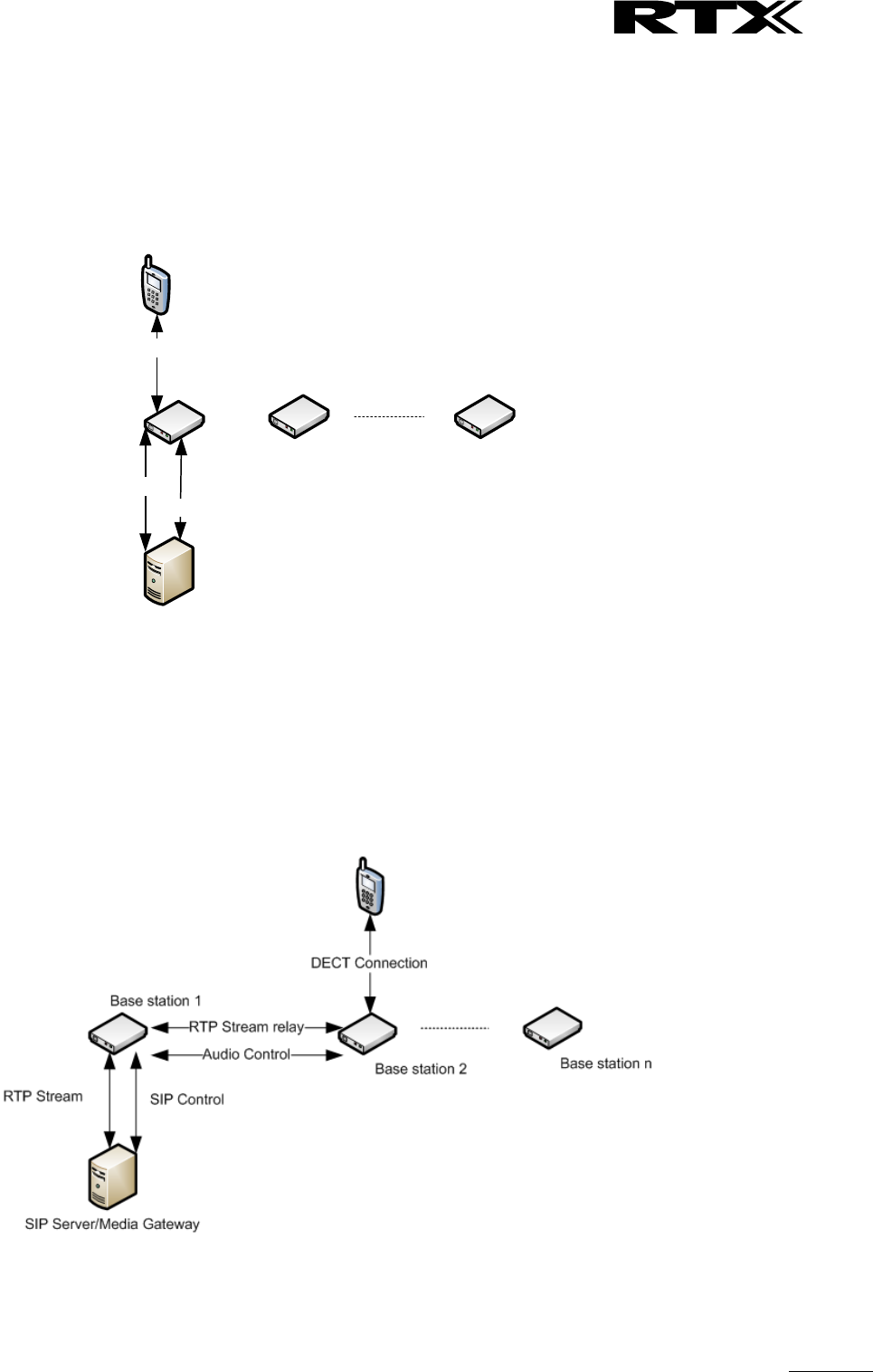
SME VoIP System Guide, Version 2.6
Proprietary and Confidential
Chapter: Appendix E: Network Operations
126
14.6 Handover
14.6.1 RTP Stream Remains at Initial Base Station
When the call is set up, the handset is located at base station 1. Thus, the DECT communication takes place
between the handset and station 1, and the SIP signalling as well as the RTP stream takes place between
base station 1 and the SIP server/media gateway. The figure below illustrates this application:
SIP Server/Media Gateway
Base station 1
DECT Connection
RTP Stream
SIP Signaling
Base station 2 Base station n
Stage 1: Before handover the handset is located at BS 1.
After handover, the handset is located at base station 2, and hence the DECT communication goes on
between the handset and base station 2. However, to avoid disruption of the audio, the RTP stream is
relayed via the initial base station, since a transfer of the RTP stream to another base station may cause the
media gateway (or whatever the remote endpoint is) to re-initialize the RTP stream with a small disruption
of the RTP stream as consequence. Thus, from the point of view of the remote endpoint, the RTP stream is
not affected by the handover, and since the call control also remains at base station 1 the SIP signalling is
also unaffected, as shown below:
Stage 2: After handover to BS 2, the HS is located at BS 2, and the RTP stream is relayed via BS 1.
Since the call control and hence the SIP User Agent remains at the initial base station, the SIP registration is
also unaffected by the handover.
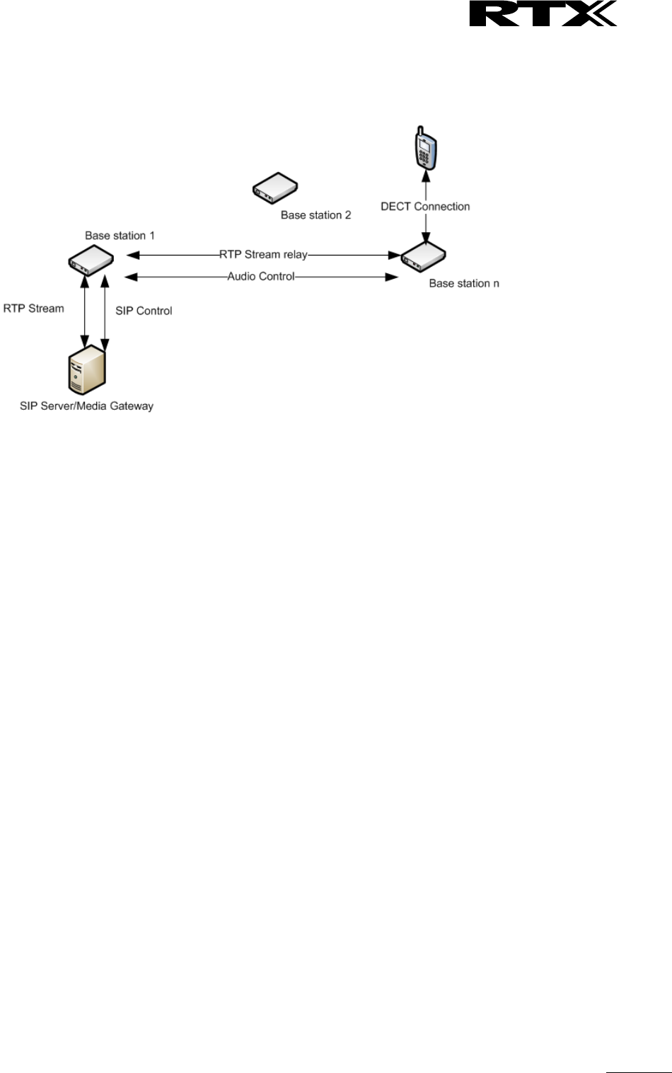
SME VoIP System Guide, Version 2.6
Proprietary and Confidential
Chapter: Appendix E: Network Operations
127
If the handset makes yet another handover, the RTP stream will still be relayed via the base station at
which, the call was established (here base station 1). This is illustrated as follows:
After handover to BS n the handset is located at BS n, and the RTP stream is relayed via BS 1.
14.7 Roaming
By roaming means the handset moves its SIP and DECT registration from one base station to another base
station. Roaming can only be initiated from idle.
Roaming does not immediately result in a new SIP registration, because this may cause a lot of unnecessary
signalling. Therefore, the handset will not perform a new DECT Location Registration until it has resided on
the same base station for a defined period of time. Since the SIP registration is initiated by the completion
of the Location Registration, a new SIP registration will also not be done until this procedure has completed
on a new base station. Thus, a handset must stay on the same base station as given in the rules stated
below, before a new SIP registration will be made.
Timing Criteria for Location Registration; or roaming will be initiated when:
1. Handsets lose contact to first base unit due to reset/power off/heavy DECT traffic.
2. After 5 minutes (configuration is possible) but before 5+2 minutes
a. The plus maximum 2 minutes will occur when service connection traffic is signaled at the same
time as location should happen. In this case the location registration procedure will be delayed.
If an incoming call arrives while the handset has moved to another base station (base station 2) but still not
performed a new Location Registration, the SIP call will arrive at the initial base station (base station 1), but
the RTP stream will be set up between base station 2 and the remote endpoint (refer to figure below).
Alternatively, in the case of an outgoing call, the SIP call will be established from the initial base station, and
the RTP stream will be set up between base station 2 and the remote endpoint.

SME VoIP System Guide, Version 2.6
Proprietary and Confidential
Chapter: Appendix E: Network Operations
128
SIP Server/Media Gateway
Base station 1
Base station 2 Base station n
RTP Stream
DECT Connection
SIP Control
Audio Control
An illustration of Handset moving to another base station, but call control is still handled by the initial base
station.
FCC Caution:
Any Changes or modifications not expressly approved by the party responsible for compliance could void
the user's authority to operate the equipment.
This device complies with part 15 of the FCC Rules. Operation is subject to the following two conditions:
(1) This device may not cause harmful interference, and (2) this device must accept any interference
received, including interference that may cause undesired operation.
Note: This equipment has been tested and found to comply with the limits for a Class B digital device,
pursuant to part 15 of the FCC Rules. These limits are designed to provide reasonable protection
against harmful interference in a residential installation. This equipment generates, uses and can
radiate radio frequency energy and, if not installed and used in accordance with the instructions, may
cause harmful interference to radio communications. However, there is no guarantee that interference
will not occur in a particular installation. If this equipment does cause harmful interference to radio or
television reception, which can be determined by turning the equipment off and on, the user is
encouraged to try to correct the interference by one or more of the following measures:
—Reorient or relocate the receiving antenna.
—Increase the separation between the equipment and receiver.
—Connect the equipment into an outlet on a circuit different from that to which the receiver is connected.
—Consult the dealer or an experienced radio/TV technician for help.
Privacy of communications may not be ensured when using this telephone!
Chapter: Appendix E: Network Operations
129
SME VoIP System Guide, Version 2.6
Proprietary and Confidential
FCC Radiation Exposure Statement:
This equipment complies with FCC radiation exposure limits set forth for an uncontrolled
environment .This equipment should be installed and operated with minimum distance 20cm between the
radiator& your body.
This transmitter must not be co-located or operating in conjunction with any other antenna or transmitter.
IC:
This device complies with Industry Canada licence-exempt RSS standard(s). Operation is subject to the
following two conditions:
(1) this device may not cause interference, and
(2) this device must accept any interference, including interference that may cause undesired operation
of the device.
Le présent appareil est conforme aux CNR d'Industrie Canada applicables aux appareils radio exempts
de licence. L'exploitation est autorisée aux deux conditions suivantes : (1) l'appareil ne
doit pas produire de brouillage, et (2) l'utilisateur de l'appareil doit accepter tout brouillage radioélectrique
subi, même si le brouillage est susceptible d'en compromettre le fonctionnement
SME VoIP System Guide, Version 2.6
Proprietary and Confidential
Chapter: Appendix E: Network Operations
130
The device is compliance with RF exposure guidelines, users can obtain Canadian information on RF
exposure and compliance.The minimum distance from body to use the device is 20cm.
Le présent appareil est conforme
Après examen de ce matériel aux conformité ou aux limites d’intensité de champ RF,
les utilisateurs peuvent sur l’exposition aux radiofréquences et la conformité and compliance d’acquérir
les informations correspondantes. La distance minimale du corps à utiliser le dispositif est de 20cm.