Racom RAY2-24 ISM Transmitter User Manual RAy2 Microwave Link
Racom ISM Transmitter RAy2 Microwave Link
UserManual.wiki
>
Racom
>
RAY2 24 User Manual
User Manual
Navigation menu
Upload a User Manual
Namespaces
Wiki Guide
HTML
PDF
Info
Views
User Manual
Discussion / Help
Navigation

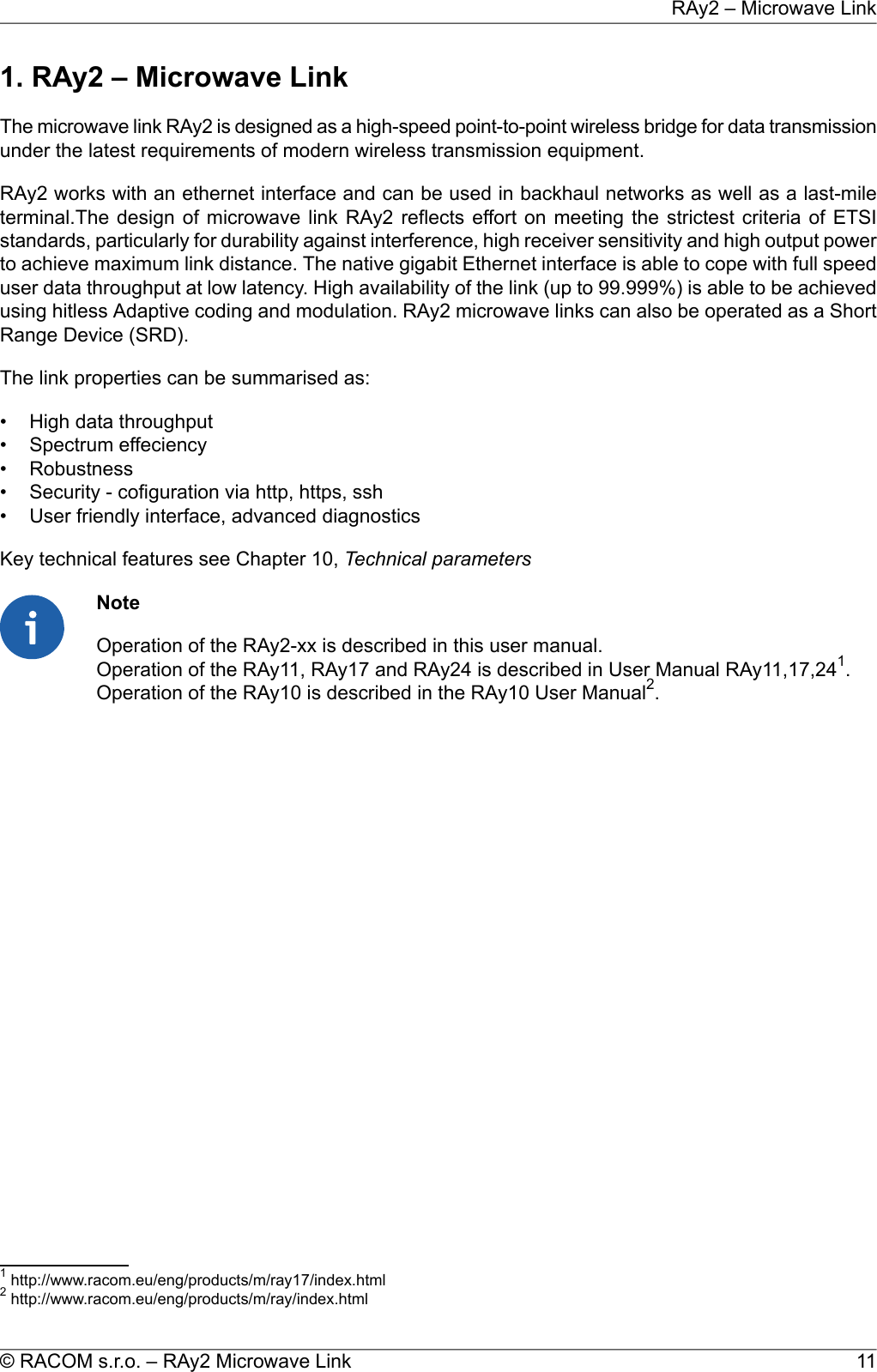
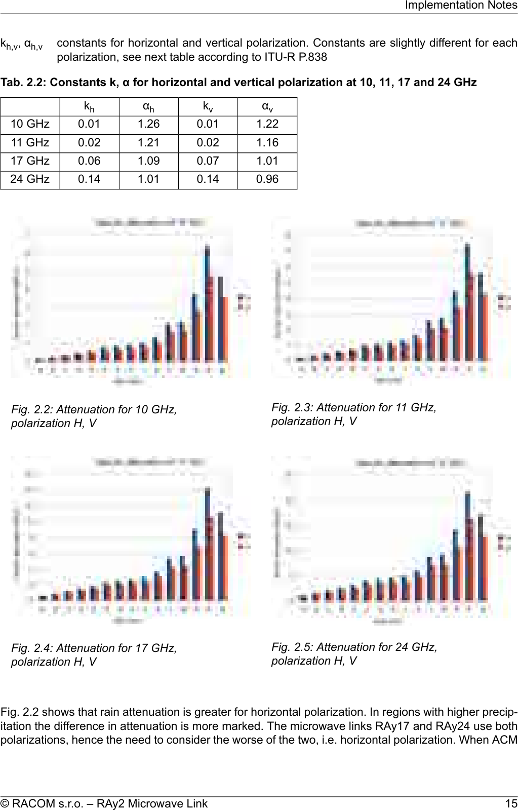
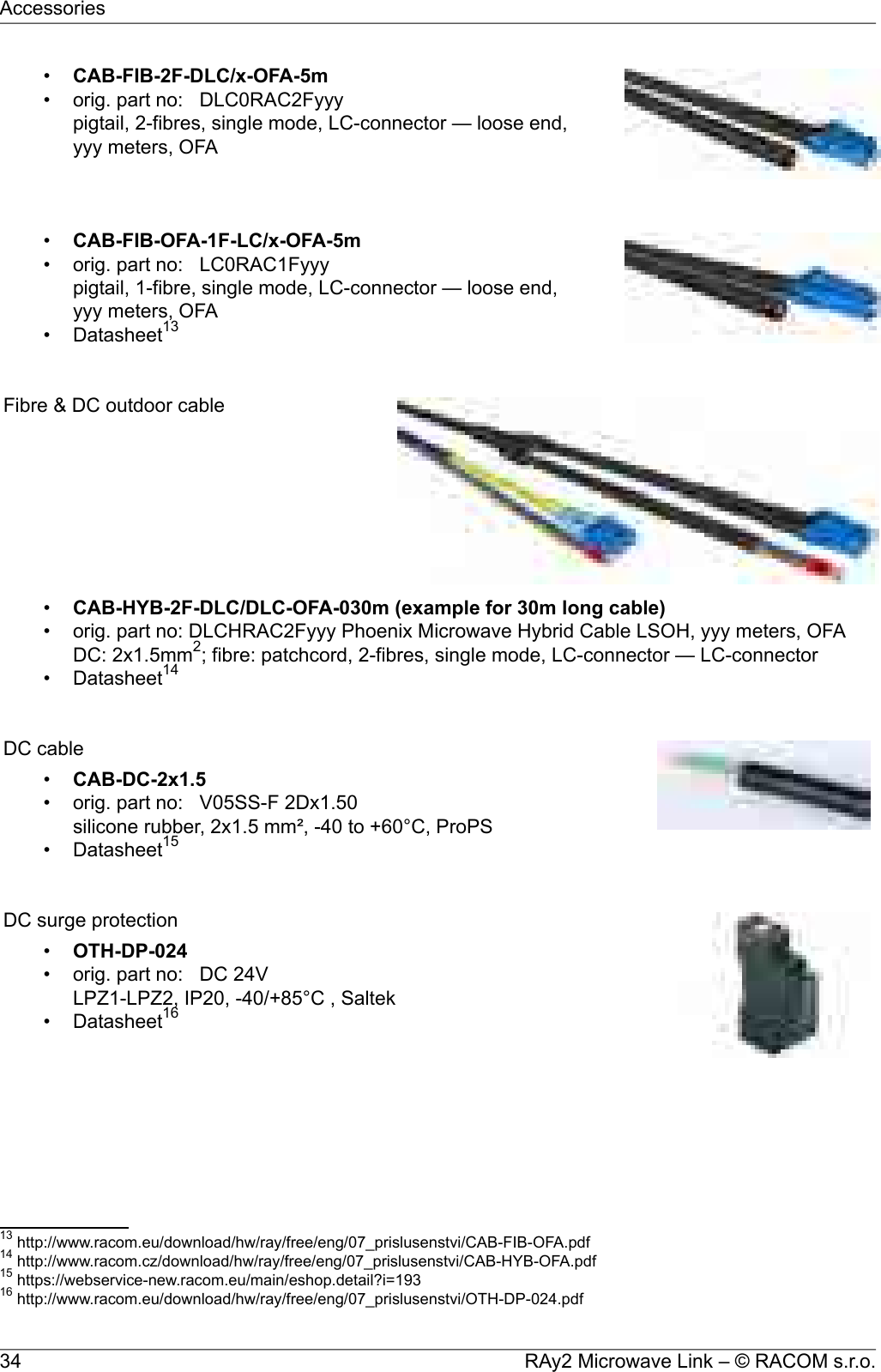
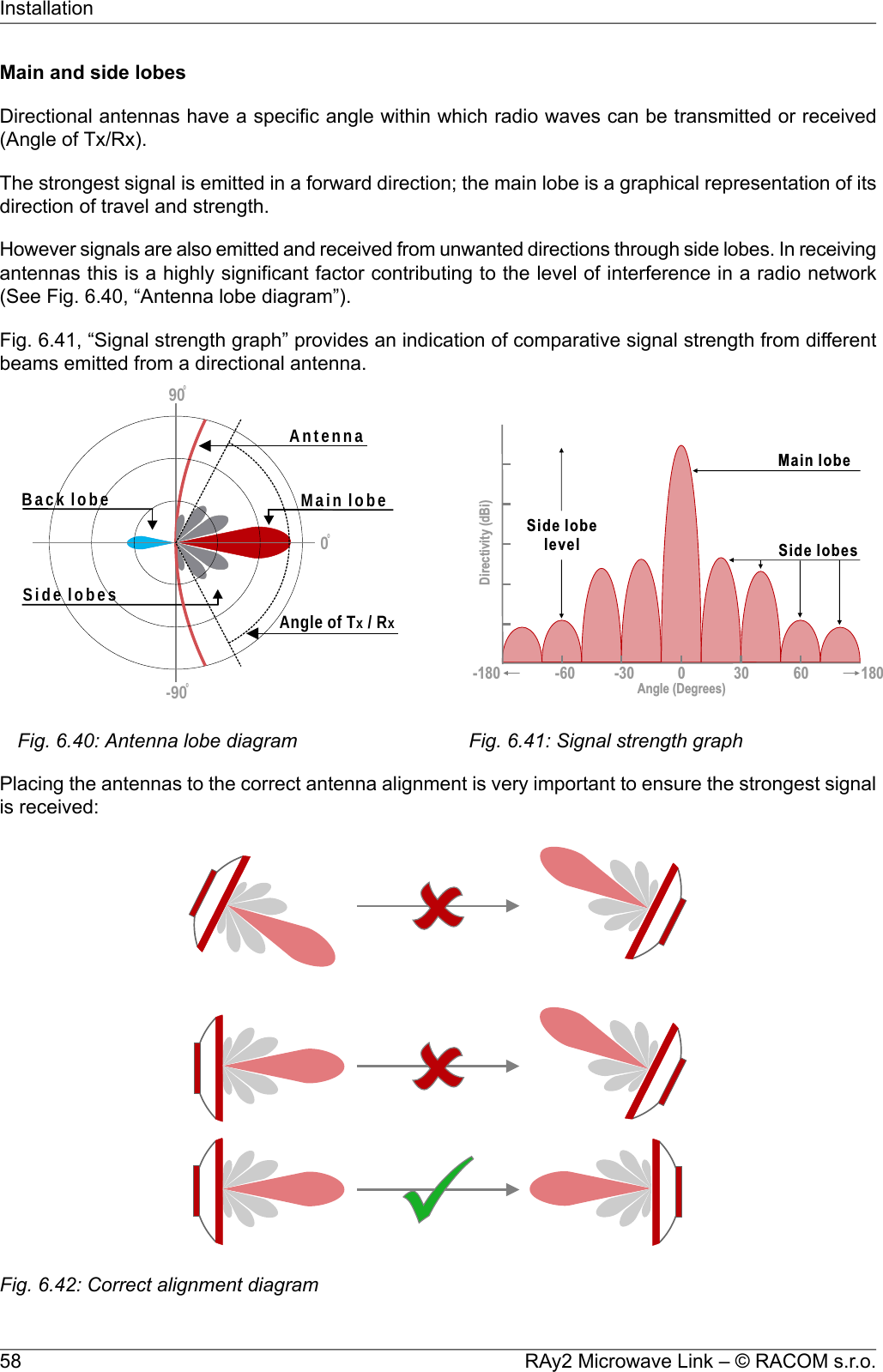
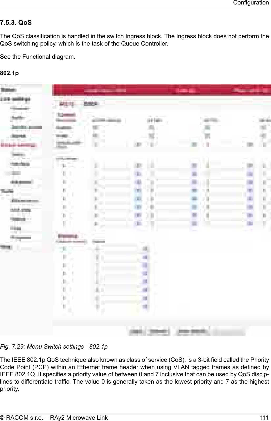
![is active we recommend using horizontal polarization in the direction with lower data traffic (typicallyup-link).2.1.5. Multipath fadingMultipath fading is another dominant fading mechanism. A reflected wave causes a phenomenon knownas multipath, meaning that the radio signal can travel multiple paths to reach the receiver. Typically,multipath occurs when a reflected wave reaches the receiver at the same time in opposite phase asthe direct wave that travels in a straight line from the transmitter.Multipath propagation gives rise to two kinds of signal degrading effects, i.e., flat fading and frequencyselective fading. Flat fading is a reduction in input signal level where all frequencies in the channel ofinterest are equally affected and is dependent on path length, frequency, and path inclination. In addition,it is strongly dependent on the geoclimatic factor K.To calculate the probability of outage due to multipath propagation of microwave links the ITU-Rprobability model can be used which describes a single frequency (or narrowband) fading distributionsuitable for large fade depths A in the average worst month in any part of the world (based on ITU-RP.530-14). The calculation for detailed link design is given as follows [1]:P0=Kd3.4(1+|εP|)-1.03f0.8×100.00067hL-A/10where:dlink distance (km)ffrequency (GHz)hLaltitude of lower antenna (m)Afade depth (dB)K is geoclimatic factor and can be obtained from:K= 10-4.6-0.0027dN1The term dN1 is provided on a 1.5° grid in latitude and longitude in ITU-R Recommendation P.453.The data are available in a tabular format and are available from the Radiocommunication Bureau(BR). E.g. in Central Europe the values dN1 range from -242 to -362.From the antenna heights heand hr(meters above sea level), calculate the magnitude of the path in-clination │εP│ (mrad) using the following expression:where:dlink distance (km)hr, heantenna heights above sea level (m)RAy2 Microwave Link – © RACOM s.r.o.16Implementation Notes](https://usermanual.wiki/Racom/RAY2-24/User-Guide-2944903-Page-16.png)
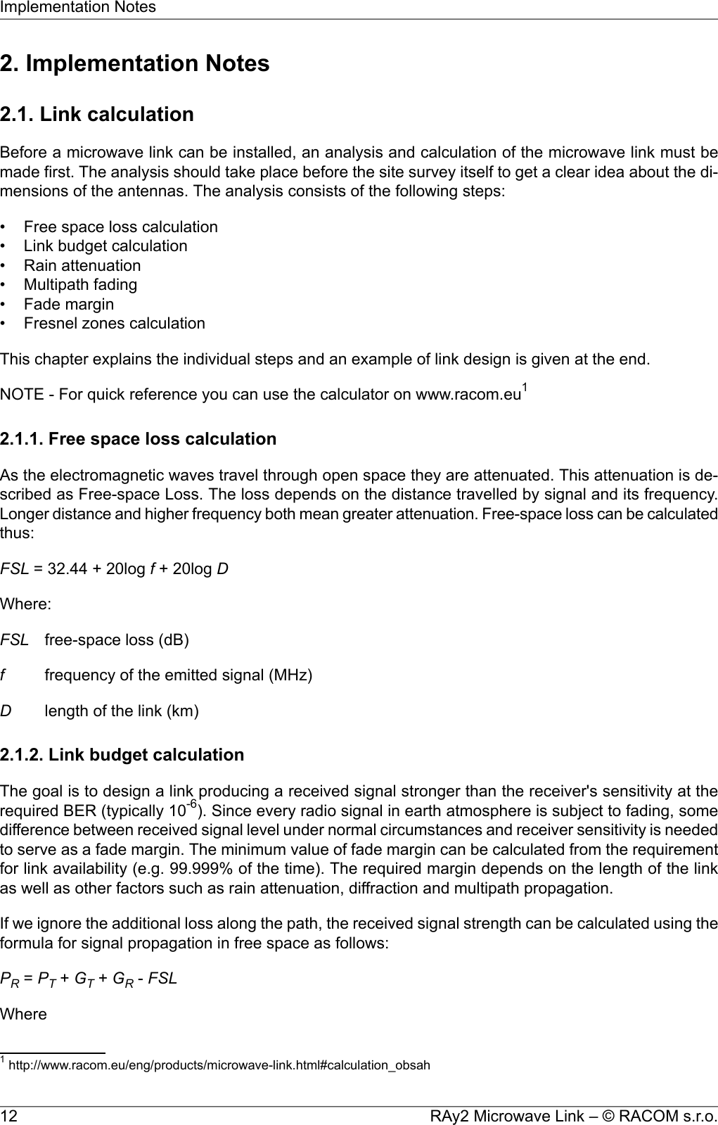
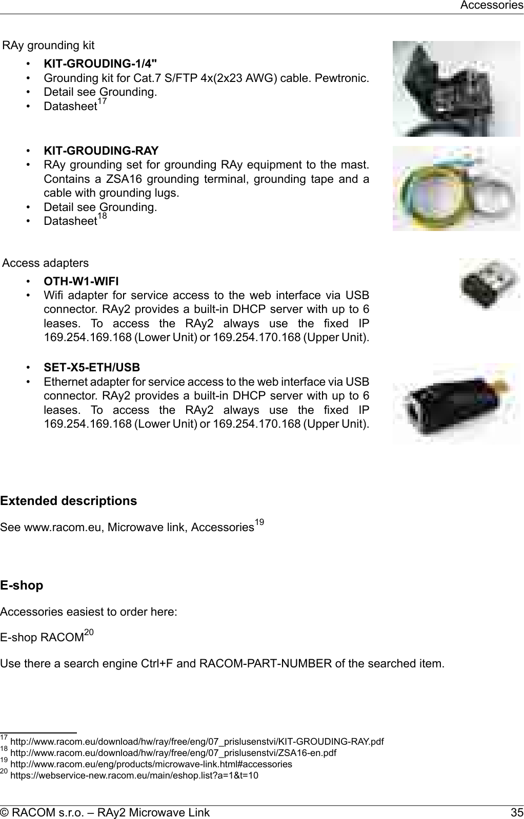
![Fade margin:A= |PS|−|PR| = 79 − 67.1 = 11.9 dBFade margin is now only 12 dB which corresponds to link availability > 99.99% of the time in a year.Technical literature often gives the minimum fade margin of 20 dB. For very long links (more than10 km) fade margin will, indeed, be approximately 20 dB. For shorter links, however, such largemargin is not necessary. It is helpful to first conduct the calculation above to receive an idea of theattenuation affecting the link.The resultTo achieve the required transmission capacity and link availability for link distance of 4 km, transmitpower -22 dBm and 99 cm antennas were selected for both sides of the link.Sources for Chapter Chapter 2, Implementation Notes:[1] Lehpamer, H.: Microwave transmission network, Second edition, ISBN: 0071701222, McGraw-HillProfessional, 2010.ITU-R recommendation used:• ITU-R P.453-10 – The radio refractive index: its formula and refractivity data• ITU-R P.530-14 – Propagation data and prediction methods required for the design of terrestrialline-of-sight systems• ITU-R P.837-1 and 6 – Characteristics of precipitation for propagation modelling• ITU-R P.838-3 – Specific attenuation model for rain for use in prediction methods• ITU-R P.310, ITU-R P.526, ITU-R P.676, ITU-R P.834, ITU-R P.835RAy2 Microwave Link – © RACOM s.r.o.20Implementation Notes](https://usermanual.wiki/Racom/RAY2-24/User-Guide-2944903-Page-20.png)
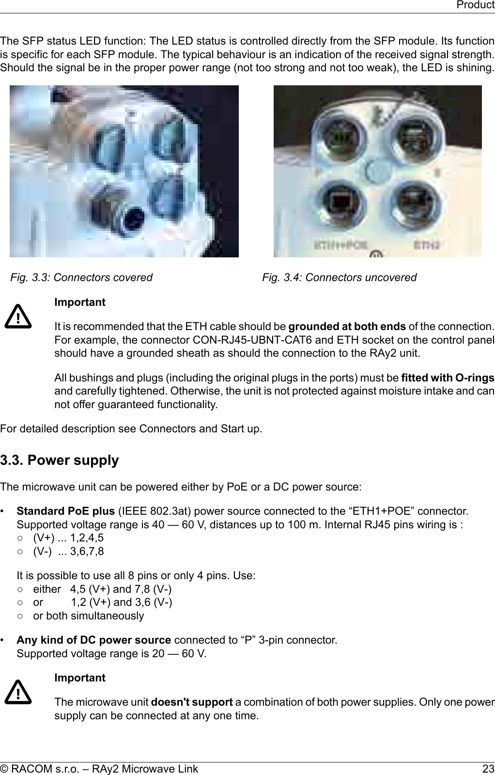
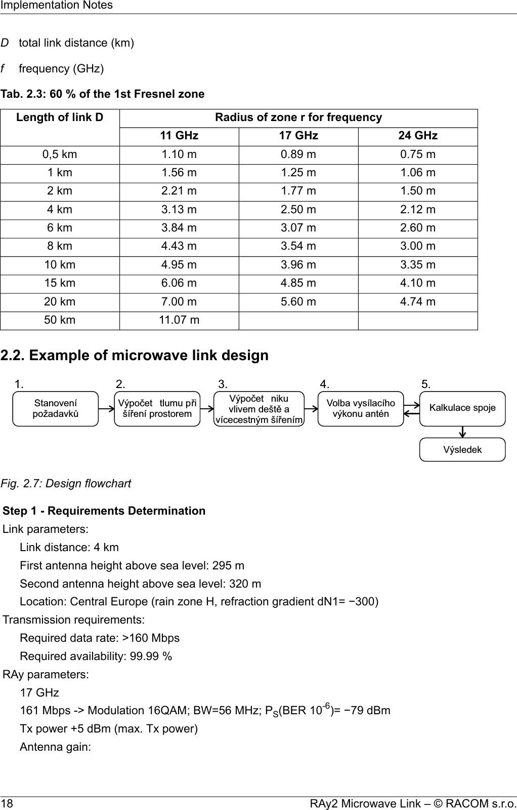
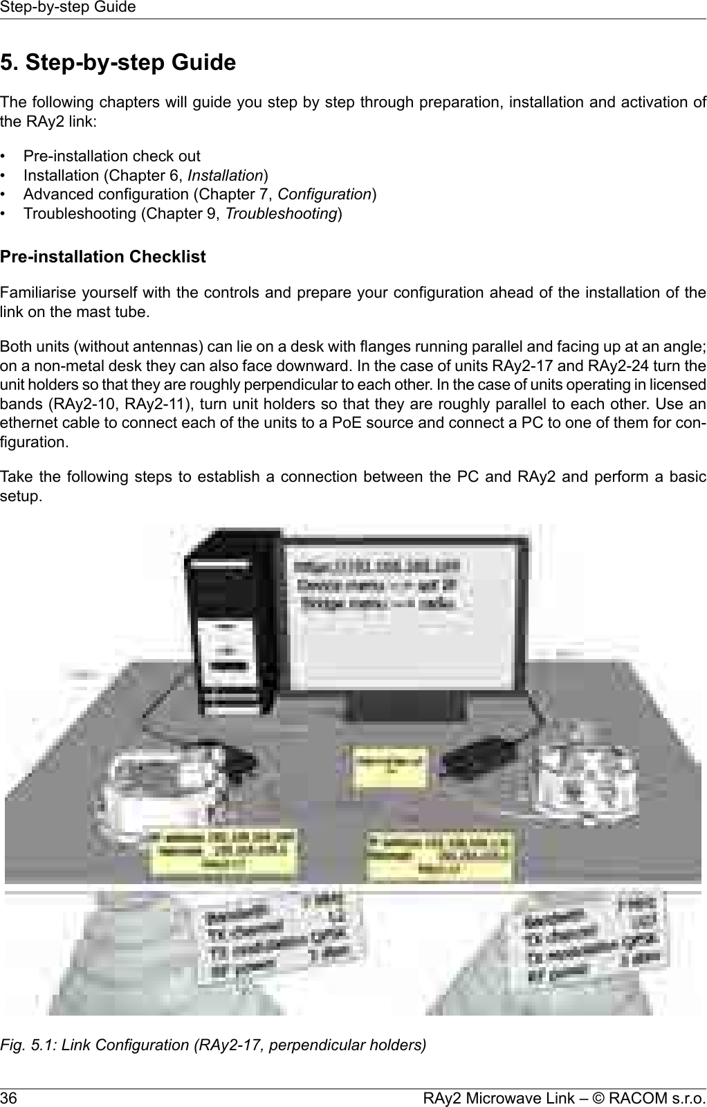
![3.7. Ordering codesThe proper pair (from the same row) of Lower and Upper units should be selected when ordering themicrowave link. This is not valid for RAy2-17 and RAy2-24 units. In such a case the same unit is usedfor both sides of the link.Tab. 3.3: Ordering codesType Frequency Ordering codeLower [GHz] Upper [GHz] Lower unit Upper unit10 GHz 10.30 – 10.42 10.47 – 10.59 RAy2-10-LA RAy2-10-UA 10.125 – 10.325 10.475 – 10.675 RAy2-10-LB RAy2-10-UB 11 GHz 10.695 – 10.970 11.185 – 11.460 RAy2-11-LA RAy2-11-UA 10.935 – 11.195 11.425 – 11.695 RAy2-11-LB RAy2-11-UB 17 GHz 17.100 – 17.300 RAy2-1718 GHz 1) 17.700 – 18.209 18.710 – 19.219 RAy2-18-LA RAy2-18-UA 18.167 – 18.690 19.177 – 19.700 RAy2-18-LB RAy2-18-UB 24 GHz 24.000 – 24.250 RAy2-24ver 5.01) RAy2-18 not available yetThe Feature keys ordering code consists of three parts:RAy2-SW- 360 Product type RAy2 Feature key type. The "SW" key is available now. This key unlocks the User speed to a given value. The default user speed without the feature key is the minimum for the respective HW unit. Feature key value. In case of User speed it states Mbps. Possible values 200, 360.SW key possibilities, valid for RAy2-10, 11, 17, 18, 24:•RAy2-SW-200 SW feature key - Capacity up to 200 Mbps•RAy2-SW-360 SW feature key - Capacity up to 200 Mbps•RAy2-SW-200-360 SW feature key - Capacity upgrade from 200 to 360 Mbps27© RACOM s.r.o. – RAy2 Microwave LinkProduct](https://usermanual.wiki/Racom/RAY2-24/User-Guide-2944903-Page-27.png)
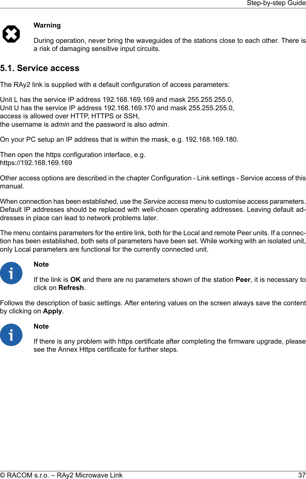
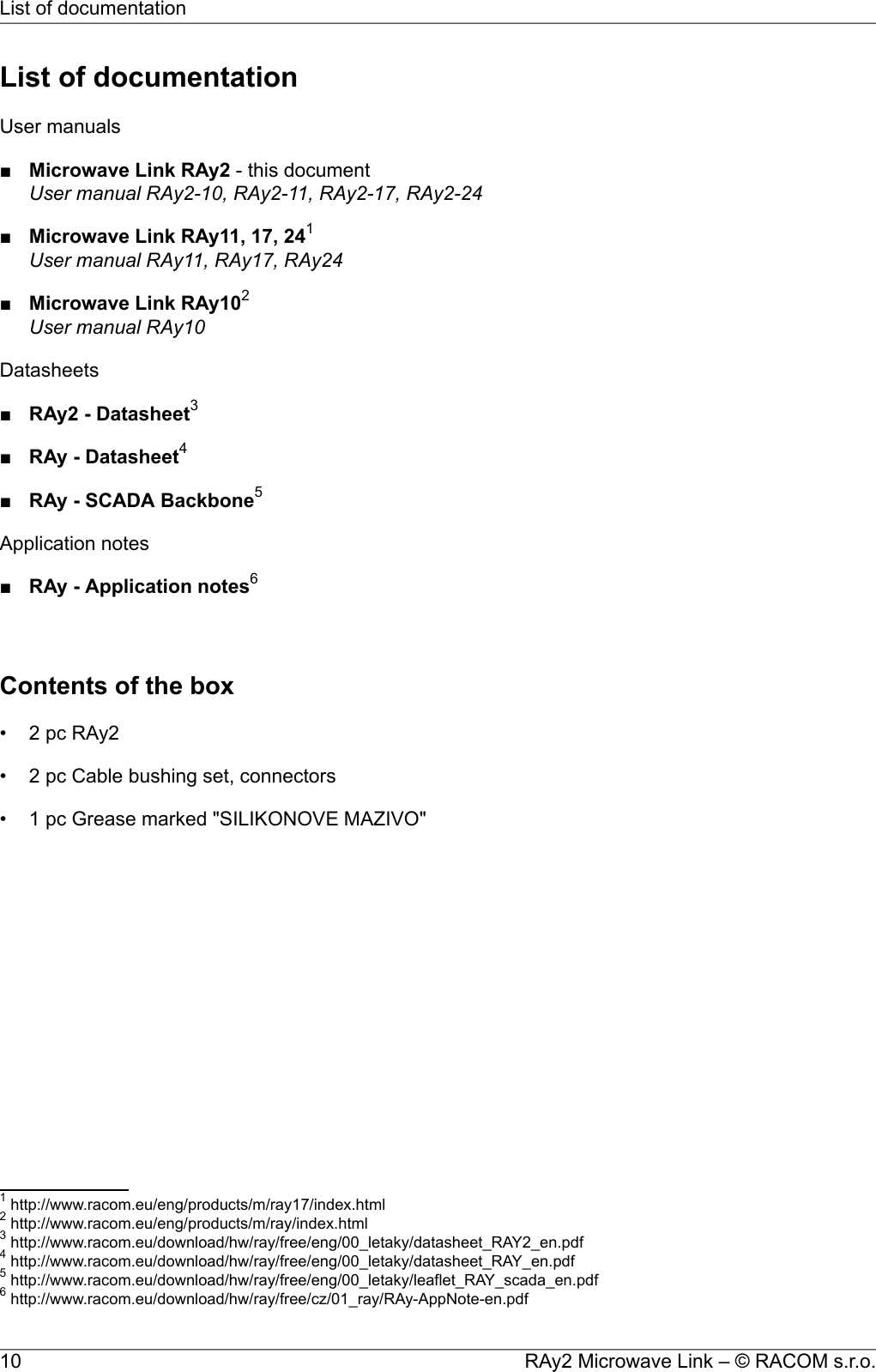
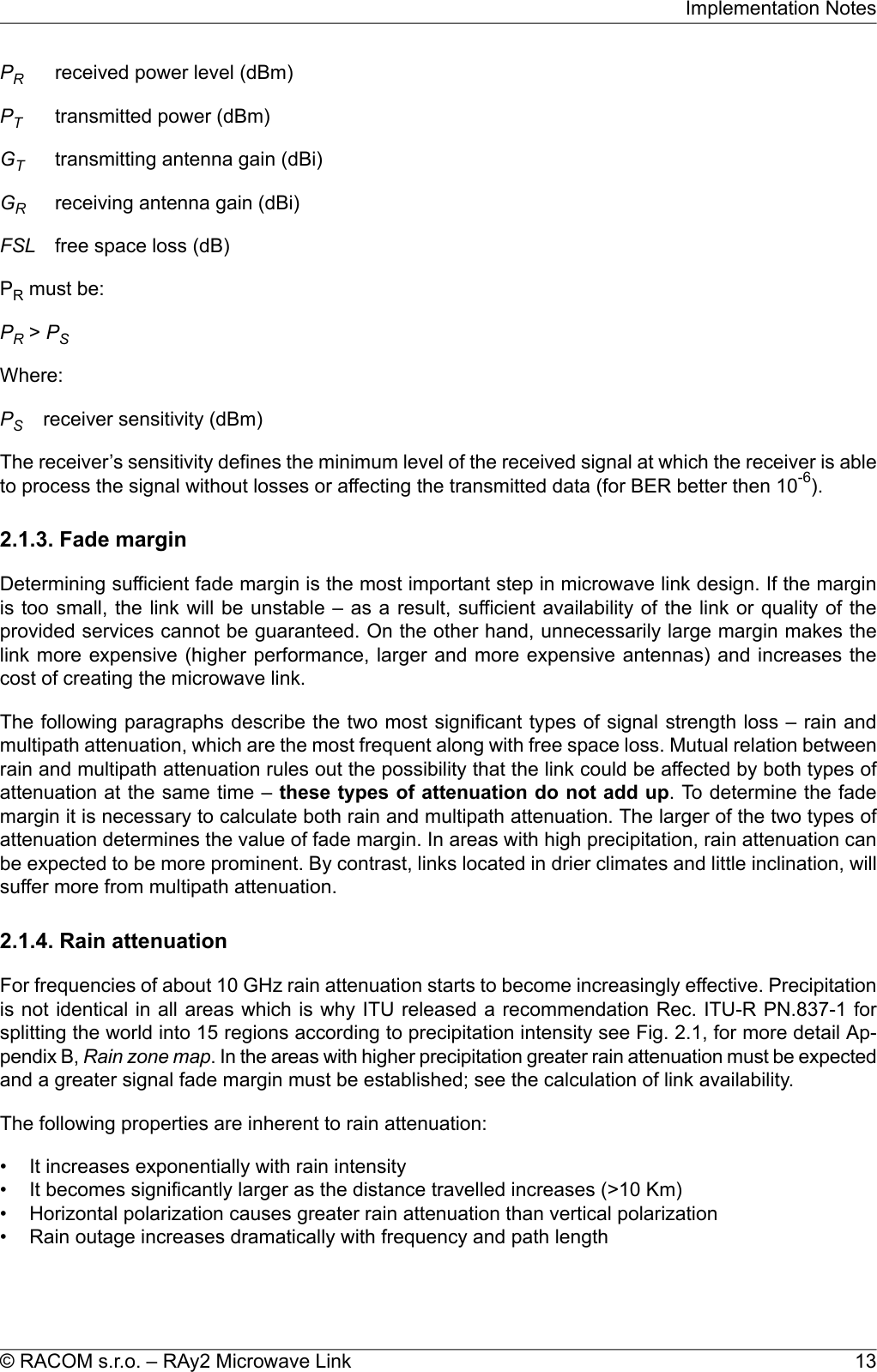
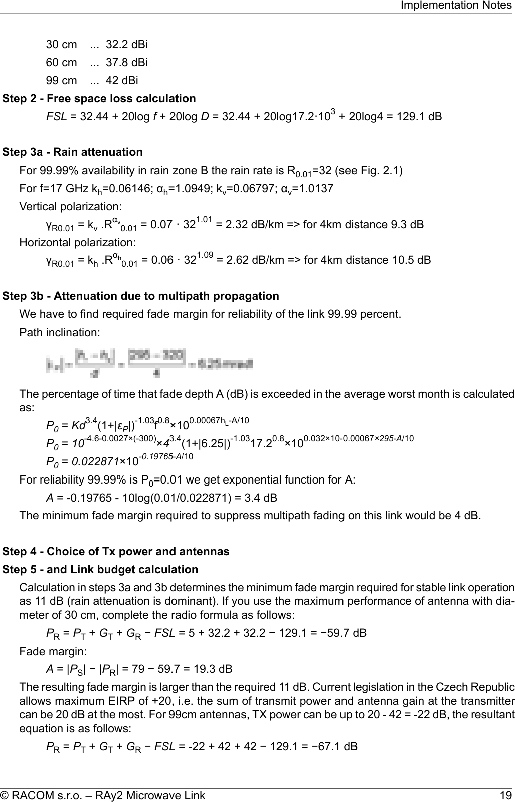
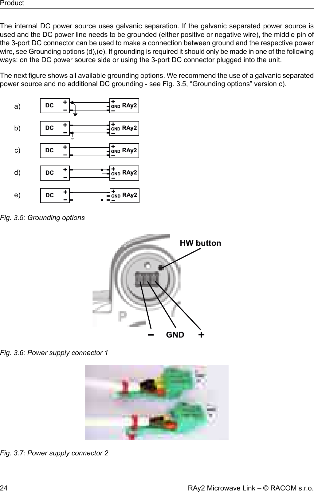
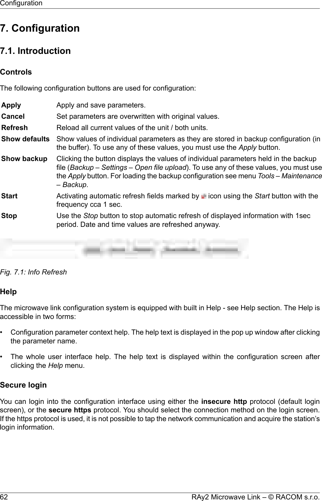
![Examples54-40°01020-10G[dbi]-20° 20° 40°0°6-40°01020-10G[dbi]-20° 20° 40°0°-40°01020-10G[dbi]-20° 20° 40°0°213A–AB–B C–CCROSS-SECTION A – ACROSS-SECTION C – C-40°01020G[dbi]-20° 20°0°MAINBEAMSIDELOBEA AB BC C40°213645Fig. 6.43: Radiation diagramsBoth antennas should be oriented towards each other using the peaks of the radiation diagram. Adjustthe antenna alternately in the horizontal and vertical axes and monitor the resulting signal strength.Use the calculation of the expected RSS with the precision of several dBm as guidance. Side lobestransmit a signal ca 20 dBm weaker, see the Microwave link Calculation3.3http://www.racom.eu/eng/products/microwave-link.html#calculation59© RACOM s.r.o. – RAy2 Microwave LinkInstallation](https://usermanual.wiki/Racom/RAY2-24/User-Guide-2944903-Page-59.png)
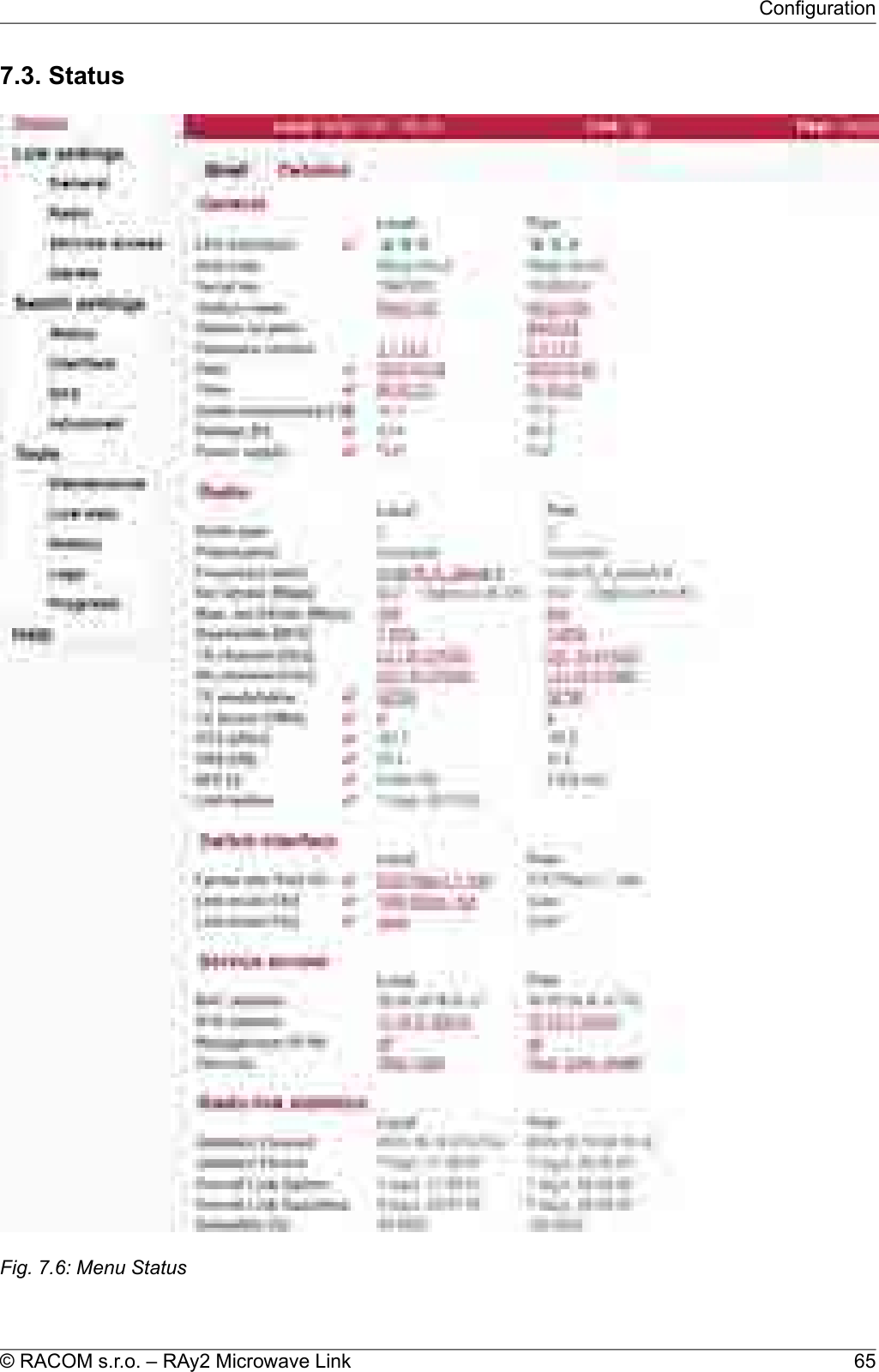
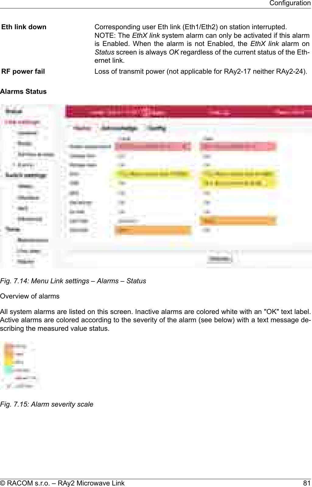
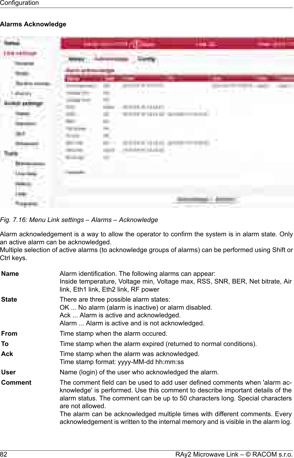
![The Status menu provides basic information about local and remote station. Informations is valid themoment the page is open, or the Refresh button is hit.The Status – Brief tab shows only the most important values whereas the Status – Detailed tabprovides further details. Below is a list of all values according to the tab Status – Detailed.The icon marks fields which are automatically updated with 30 sec period (or 1 sec when the Startbutton is active).7.3.1. Status - GeneralLED indicators Unit status indication- Radio link OK- Radio link interruptedGreenRedA - AIR- System OKGreenS - SYS- ETH1 port - Link 10/100/1000- ETH2 port - Link 10/100/1000GreenOrangeE - ETHUnit type indicator.Unit codeUnit serial number.Serial no.Station name assigned by user.Station nameStation location assigned by user.Station locationUnit’s firmware version.Firmware versionThe internal real-time clock. The clock is set manually or it is synchronizedwith NTP server and set for both units.Date, TimeTemperature inside the unit (on the modem board).Inside temperature [°C]Unit’s power supply voltage level.Voltage [V]The power supply input the unit is powered from.PoE - unit is powered via Ethernet cable plugged into port "ETH1+POE".AUX - unit is powered via DC cable plugged into port "P".Power supply7.3.2. Status - RadioRadio unit type: L (Lower) or U (Upper) part of the frequency band.Radio typeHorizontal or vertical polarization based on the physical installation. Indic-ates the polarization of the received signal. Local and Peer are indicatedseparately. The proper position of the cable is sideways down.Notice for RAy2-17 and RAy2-24 links: One side of the link must be installedin vertical polarization and the other in horizontal polarization.PolarizationDisplays the currently used frequency table in format <name:version>.Frequency tableCurrent transfer capacity of radio channel for user data.Net bitrate [Mbps]The maximum RF channel capacity according to installed feature key.Max. net bitrate [Mbps]One of the standard channel widths can be selected. This parameter mustbe set identically in local and remote.Bandwidth [MHz]Used channels. Both number of the channel and frequency in GHz arelisted.TX and RX channel [GHz]Modulation type currently used for transmitting. When adaptive modulationis enabled, the ACM letters are displayed as well as information aboutTX modulationRAy2 Microwave Link – © RACOM s.r.o.66Configuration](https://usermanual.wiki/Racom/RAY2-24/User-Guide-2944903-Page-66.png)
![maximum permitted modulation: “current modulation ACM / maximummodulation”Current output power on the RF channel in dBm. If ATPC is enabled, theATPC letters are displayed as well as information about maximum permittedpower: “current power ATPC / maximum power”TX power [dBm]Received signal strength. If ATPC is enabled, the ATPC letters are dis-played as well as information about threshold value for activation of powerRSS [dBm]67© RACOM s.r.o. – RAy2 Microwave LinkConfiguration](https://usermanual.wiki/Racom/RAY2-24/User-Guide-2944903-Page-67.png)
![control loop: “current RSS ATPC / threshold RSS”Signal to Noise Ratio. If ATPC is enabled, the ATPC letters are displayedas well as information about threshold value for activation of power controlloop: “current SNR ATPC / threshold SNR”SNR [dB]Bit Error Rate is registered at the receiving end; instantaneous value.BER [-]Time elapsed since the current link connection has been established.Link uptime7.3.3. Status - Switch interfaceEgress rate limit Air Status of the Egress rate limitter on the Air interface. The traffic can belimitted according to bits per second or frames per second.Message format for bits per second: "xx.xx Mbps Ly auto" where:Egress speed limit.xx.xx MbpsL1/L2/L3 which Ethernet layer is used for speed calculation.Lygives information about active Speed guard function.autoMessage format for frames per second: "xx.xx fps" where:Egress frames per second limit.xx.xx fpsStatus of ethernet interface. Current bit rate (10 = 10BASE-T, 100 =100BASE-TX and 1000 = 1000BASE-T) and state of duplex (FD = full du-plex, HD = half duplex).Link mode Eth1, 27.3.4. Status - Service accessHW address of the Ethernet module.MAC addressIP address in the standard dotted decimal notation, including the bit widthof netmask after the forward slash.IPv4 addressService access via VLAN management only.Management VLANServices enabled for unit management and monitoring (Web, Telnet, SSH,SNMP, NTP).Services7.3.5. Status - Radio link statisticsInformation on statistical data:Time of log clearing.Statistics ClearedPeriod of log refresh.Statistics PeriodRadio link statistics:Overall time the link has been connected.Overall Link UptimeOverall time the link has been disconnected.Overall Link DowntimeThe ratio of Uptime and Downtime.Reliability [%]Current time the link has been connected.Current Link UptimeThe longest downtime period recorded.The Longest DropLength of the last link interruption.The Last DropNumber of link interruptions.Number of DropsRAy2 Microwave Link – © RACOM s.r.o.68Configuration](https://usermanual.wiki/Racom/RAY2-24/User-Guide-2944903-Page-68.png)
![Radio unit type: L(ower) or U(pper) part of the frequency band.Radio typeHorizontal or vertical polarization based on the physical installation. Indic-ates the polarization of the received signal. Local and Peer are indicatedseparately. The proper position of the cable is sideways down.Notice for RAy2-17 and RAy2-24 links: One side of the link must be installedin vertical polarization and the other in horizontal polarization.PolarizationOne of the standard channel widths can be selected. This parameter mustbe set identically in local and remote.Bandwidth [MHz]Enable manual input (if supported). TX and RX frequencies [GHz] aremanually entered. It is possible to disconnect the TX-RX lock and selectFrequency inputTX and RX channels individually. Corresponding channels at peer unit areset automatically.TX and RX channels are selected from a list of channels. The basic con-figuration has the TX and RX options interconnected. In this case the basicTX channel [GHz]RX channel [GHz] duplex spacing between channels is preserved and by selecting onechannel, the other three are defined as well. For units operating in freebands, it is possible to disconnect the TX-RX lock and select TX and RXchannels individually. Corresponding channels at peer unit are set auto-matically.NOTE: Non-standard duplex setting leads to non-effective use of thespectrum.Information about duplex spacing of TX and RX channel.Duplex spacing [MHz]Enable automatic control of modulation.ACMModulation level for TX channel. You can select in range from QPSK (highsensitivity for difficult conditions) to 256QAM (high speed under appropriateTX modulationconditions). With ACM enabled the modulation will automatically operatefrom QPSK to the selected modulation.Enable automatic control of RF power.Power is regulated towards lower level while maintaining signal level highenough not to affect current degree of modulation.ATPCThe ATPC algorithm controles the output power according to RSS of thepeer unit. The lowest allowed RSS (the threshold) is approx. 10 dBm aboveATPC RSS threshold[dBm]declared sensitivity for BER 10-6. If necessary, it is possible to use thisparameter to move the threshold slightly up or down.RF output power. With ATPC enabled this parameter defines maximumRF power level.TX power [dBm]Valid only for RAy2-17 and RAy2-24 links.Gain of used antenna. It is used to calculate approximate EIRP.Antenna gain [dBi]Valid only for RAy2-17 and RAy2-24 links.Approximate calculation of EIRP. Number on the right shows the allowedEIRP limit. Sign between numbers gives information on compliance /noncompliance with allowed EIRP limits.EIRP ?= limit [dBm]71© RACOM s.r.o. – RAy2 Microwave LinkConfiguration](https://usermanual.wiki/Racom/RAY2-24/User-Guide-2944903-Page-71.png)
![7.4.4. AlarmsAlarms ConfigFig. 7.13: Menu Link settings – Alarms – ConfigThe diagnostic system of the link monitors the operation of the unit.It generates various output of events - system warnings and alarms. The event is always written to thesystem log and indicated in the status bar and Alarms-Status screen. Some events have adjustablethresholds. Events with no adjustable thresholds may or may not be Enabled. If they are not Enabled,the system event is not activated even if the system status is changed.If the event goes above or below the set parameter limits or a link goes down or up, you can chooseto send an SNMP trap.descriptiondefaultalarmTemperature inside the unit (on the modem board.)>80Inside temper. [°C]Lower threshold of supply voltage.<40Voltage min [V]Upper threshold of supply voltage. There is the same SNMP trap(same OID) both for Voltage min and max.>60Voltage max [V]Received Signal Strength.<−80RSS [dBm]Signal to Noise Ratio.<10SNR [dB]Bit Error Rate registered at the receiving end; instantaneous value.>10e−6BER [-]The system warning is generated when the current transfer capacity ofradio channel is lower than the threshold set in this parameter.0Net bitrate [Mbps]Interruption of radio link.tickedAir link downRAy2 Microwave Link – © RACOM s.r.o.80Configuration](https://usermanual.wiki/Racom/RAY2-24/User-Guide-2944903-Page-80.png)
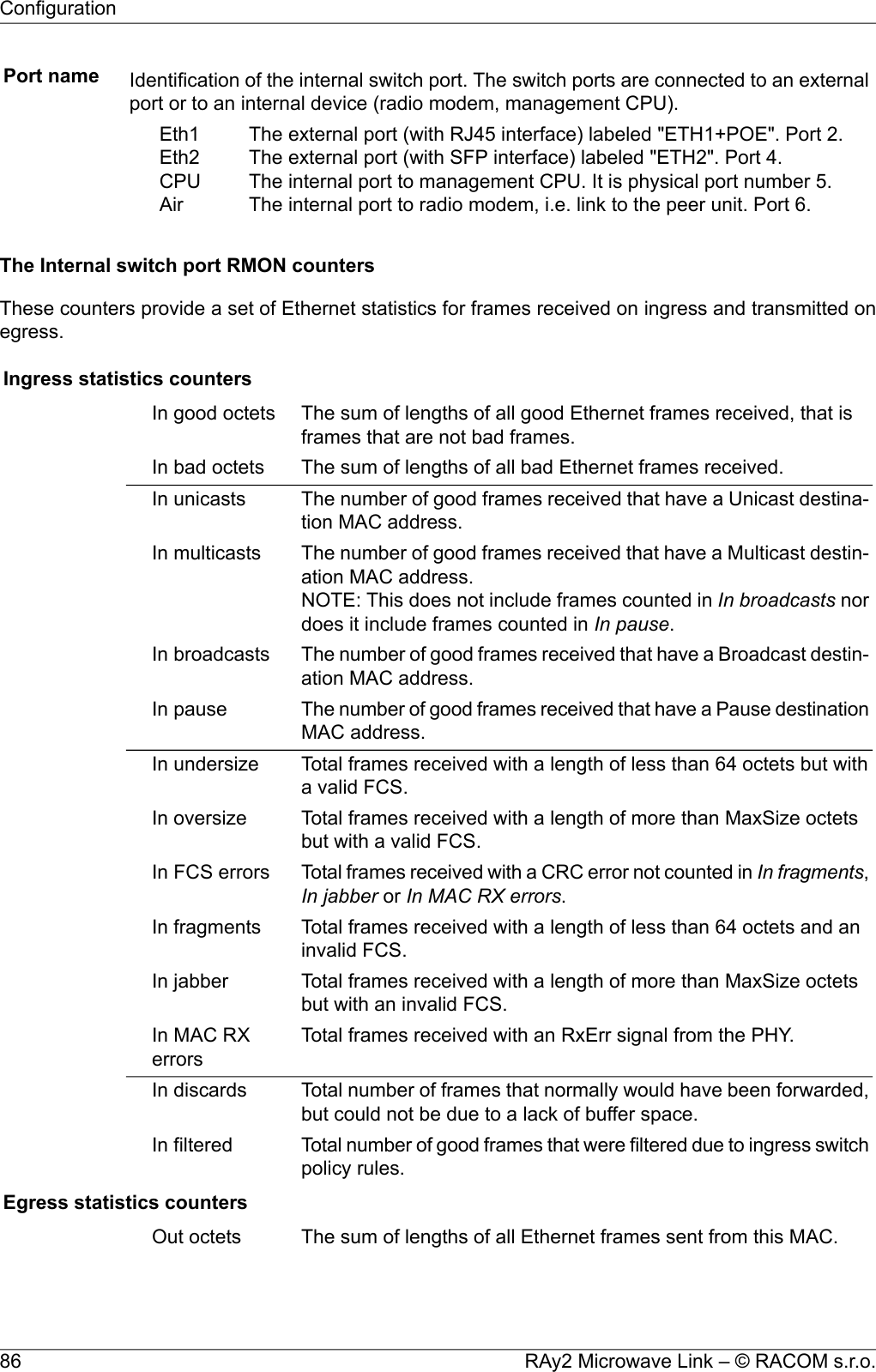
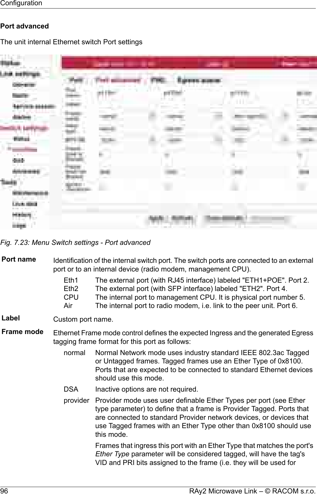
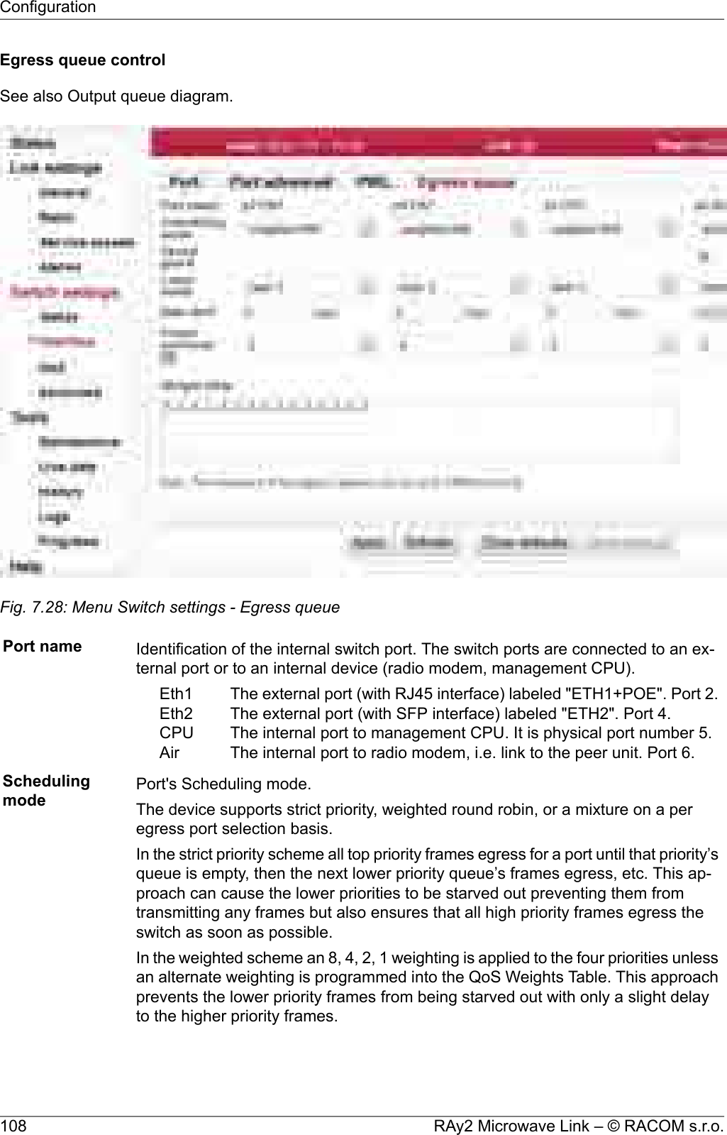
![Queue allocationFig. 7.19: Menu Switch settings - Queue allocationFree queue Free Queue Size Counter. This counter reflects the current number of unallocated buffersavailable for all the ports [buffers].Port name Identification of the internal switch port. The switch ports are connected to an ex-ternal port or to an internal device (radio modem, management CPU).The external port (with RJ45 interface) labeled "ETH1+POE". Port 2.The external port (with SFP interface) labeled "ETH2". Port 4.The internal port to management CPU. It is physical port number 5.The internal port to radio modem, i.e. link to the peer unit. Port 6.Eth1Eth2CPUAirIngress ... This counter reflects the current number of reserved Ingress buffers assigned to this port[buffers].Egress ... This counter reflects the current number of Egress buffers switched to this port. This isthe total number of buffers across all priority queues [buffers].Queue 0~3[buffers] Those counters reflect the current number of Egress buffers switched to this port for indi-vidual priority queues [buffer].89© RACOM s.r.o. – RAy2 Microwave LinkConfiguration](https://usermanual.wiki/Racom/RAY2-24/User-Guide-2944903-Page-89.png)
![switching and mapping), and will have the Provider Tag removed fromthe frame. If subsequent Provider Tags are found following the 1stProvider Tag, they too will be removed from the frame with their VIDand PRI bits being ignored. Modified frames will be padded if required.Frames that ingress this port with an Ether Type that does not matchthe Ether Type parameter will be considered untagged. The ingressingframes are modified so they are ready to egress out Customer ports(Normal Network Frame Mode ports) unmodified.Frames that egress this port will always have a tag added (even if theywere already tagged). The added tag will contain this port's Ether Typeas its Ether Type. The PRI bits will be the Frame Priority FPri assignedto the frame during ingress. The VID bits will be the source port's DefaultVID bits (if the source port was in Normal Network mode), or the VIDassigned to the frame during ingress (if the source port was in Providermode).Valid only for the "p5 CPU" port.ethertype DSA Ether Type DSA mode uses standard Marvell DSA Tagged frame in-formation following a user definable Ether Type (see Ether type para-meter). This mode allows the mixture of Normal Network frames withDSA Tagged frames and is useful on ports that connect to a CPU.Frames that ingress this port with an Ether Type that matches the port's"Ether Type" will be considered DSA Tagged and processed accordingly.The frame's Ether Type and DSA pad bytes will be removed so theresulting frame will be ready to egress out Marvell DSA Tag Mode portsunmodified. Frames that ingress this port with a different Ether Typewill be considered Normal Network Frames and processed accordingly.Marvell DSA Tag control frames that egress this port will always getthe port's "Ether Type" inserted followed by two pad bytes of 0x00 beforethe DSA Tag. Marvell DSA Tag Forward frames that egress this portcan egress just like the control frames (with the added Ether Type andpad) or they can egress as if the port was configured in Normal Networkmode. This selection is controlled by the port's Egress Mode bits above.Frame type Ethernet frame type (often called EtherType) is used to indicate which protocol isencapsulated in the payload of an Ethernet Frame. This parameter is important whenone protocol is encapsulated to another protocol.Examples:CommentStandardEth. typeDouble-tagged, Q-in-Q or C-tag stacking on C-tag. C-tag in IEEE 802.1ad framesIEEE 802.1q0x8100S-TagIEEE 802.1ad0x88a8S-Tag (backbone S-Tag)IEEE 802.1ah0x88e7It is used very often. For example an old non-standard802.1QinQ protocol uses this value.-0x9100See http://en.wikipedia.org/wiki/EtherType for futher details.MTU [B] MTU determines the maximum frame size allowed to be received or transmitted fromor to a given physical port. This implies that a Jumbo frame may be allowed to be97© RACOM s.r.o. – RAy2 Microwave LinkConfiguration](https://usermanual.wiki/Racom/RAY2-24/User-Guide-2944903-Page-97.png)
![received from a given input port but may or may not be allowed to be transmitted outof a port or ports. The possible values are 1522, 2048 and 10240 Bytes.NOTE: The definition of frame size is counting the frame bytes from MAC_DAthrough Layer2 CRC of the frame.Pause limit in[frame] Limit the number of continuous Pause refresh frames that can be received on thisport (if full-duplex) or the number of 16 consecutive collisions (if half-duplex). Whena port has flow control enabled, this parameter can be used to limit how long this portcan be Paused or Back Pressured off to prevent a port stall through jamming.The Flow Control on the port is (temporarily) disabled when the Pause refresh framescount exceeds the value of this parameter.Setting this parameter to 0 will allow continuous jamming to be received on thisport.Pause limit out[frame] Limit the number of continuous Pause refresh frames that can be transmitted fromthis port – assuming each Pause refresh is for the maximum pause time of 65536slot times. When full-duplex Flow Control is enabled on this port, this parameter isused to limit the number of Pause refresh frames that can be generated from thisport to keep this port’s link partner from sending any data.Clearing this parameter to 0 will allow continuous Pause frame refreshes to egressthis port as long as this port remains congested.Setting this parameter to 1 will allow 1 Pause frame to egress from this port foreach congestion situation.Setting this parameter to 2 will allow up to 2 Pause frames to egress from thisport for each congestion situation, etc.Ignore Framechecksum Ignore Frame checksum (FCS) - or in other words - Force good FCS in the frame. Whenthis parameter is not set (default behaviour), frames entering this port must have a goodCRC or else they are discarded. When this parameter is set, the last four bytes of framesreceived on this port are overwritten with a good CRC and the frames are accepted bythe switch (assuming that the frame’s length is good and it has a destination).RAy2 Microwave Link – © RACOM s.r.o.98Configuration](https://usermanual.wiki/Racom/RAY2-24/User-Guide-2944903-Page-98.png)
![PIRLPIRL (Port based Ingress Rate Limiting) has the task of arranging the transfer of frames; ensuring asfew frames as possible are discarded and that ports are not blocked.Diagram of framework processing options are available within the QoS, PIRL and Egress queue controlmenus:IP header3-rd layer6 bitsportportL2switchingblock0VLAN2-nd layer3 bitsQoSWeight tableSchedulingmodeRate[kbps][fps]Queuedefaultqueue802.1pMappingTra fictypefFrametypeLeakybucketDefaultAND/ORPriorityrateDSCPMappingPreferlenght, typeQPriQPriPri 3–0Bucket 0–4Priorityoverriding1. VLAN based2. SA based3. DA based3210QoS PIRLFRAMEEgress queue control3210Def.prior.bucketparams.follow other portsFig. 7.24: PIRL and queuesFrameThe frame comes via port, has a certain length and MAC addresses SA and DA. The IP header carriesthe DSCP priority and may also carry the 802.1p VLAN priority.QoSThe Queue priority (QPri) is created based on preferences within the DSCP or 802.1p priority. Thispriority takes values from 0 to 3, and controls the processing of frames inside the switch.• Untagged frames are provided with 802.1p priority by default.• Priorities may be remapped.• The priority can also be overwritten by the Advanced menu priority derived from a VLAN, SA and/orDA addresses.The Frame priority (FPri) is processed in a similar manner. Frame coming from the network and framebeing sent to the network is marked by this priority.PIRLBetween the port and the common switch there may be between 1 and 5 “flow restrictors” working inparallel according to the schedule “leaky bucket”. These are called “Resource”. This is analogous to99© RACOM s.r.o. – RAy2 Microwave LinkConfiguration](https://usermanual.wiki/Racom/RAY2-24/User-Guide-2944903-Page-99.png)
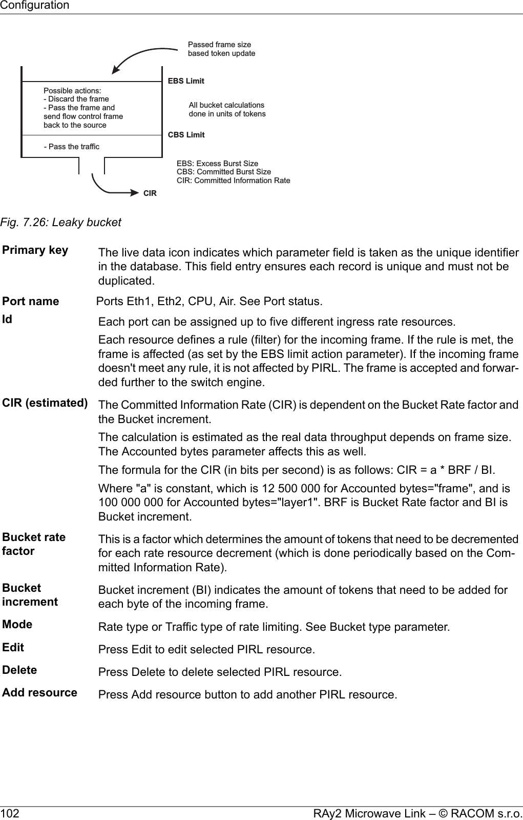

![Each resource defines a rule (filter) for the incoming frame. If the rule is met, the frame is affected (asset by the EBS limit action parameter). If the incoming frame doesn't meet any rule, it is not affectedby PIRL. The frame is accepted and forwarded further to the switch engine.Port name Identification of the internal switch port. The switch ports are connected to an ex-ternal port or to an internal device (radio modem, management CPU).The external port (with RJ45 interface) labeled "ETH1+POE". Port 2.The external port (with SFP interface) labeled "ETH2". Port 4.The internal port to management CPU. It is physical port number 5.The internal port to radio modem, i.e. link to the peer unit. Port 6.Eth1Eth2CPUAirId Each port can be assigned up to five different ingress rate resources.Each resource defines a rule (filter) for the incoming frame. If the rule is met, theframe is affected (as set by the EBS limit action parameter). If the incoming framedoesn't meet any rule, it is not affected by PIRL. The frame is accepted and forwar-ded further to the switch engine.CIR (estimated) The Committed Information Rate (CIR) is dependent on the Bucket Rate factor andthe Bucket increment.The calculation is estimated as the real data throughput depends on frame size.The Accounted bytes parameter affects this as well.The formula for the CIR (in bits per second) is as follows: CIR = a * BRF / BI.Where "a" is constant, which is 12 500 000 for Accounted bytes="frame", and is100 000 000 for Accounted bytes="layer1". BRF is Bucket Rate factor and BI isBucket increment.Burst allocation[b] The Burst allocation (BA) is dependent of the Bucket increment, the CommittedBurst Size limit and the Excess Burst Size limit.The formula for the BA is as follows: BA = 8 * (EBS-CBS) / BI.Where EBS is the Excess Burst Size limit, CBS is the Committed Burst Size limitand BI is the Bucket increment.The Burst allocation size should be less than switch internal memory which is 1Mb.CBS min The minimum value for the CBS limit is related to the maximum frame size andBucket increment.The CBS limit should always be bigger than the CBS min.The calculation for CBS min is as follows:CBS min = BI * MaxFrameSize [bytes].Where BI is the Bucket increment.If the CBS limit is lower than this value (i.e. to allow a large burst), then an ingressstream composed of maximum sized frames may exceed the Committed InformationRate. It is for this reason that we recommend the CBS limit value always staysabove the CBS min value. Also, the CBS limit should never exceed the EBS limit.EBS limit Excess Burst Size limit.The EBS limit should always be bigger than CBS limit. It is recommended that theEBS limit be set to 16777200.CBS limit Committed Burst Size limit. This indicates the committed information burst amount.RAy2 Microwave Link – © RACOM s.r.o.104Configuration](https://usermanual.wiki/Racom/RAY2-24/User-Guide-2944903-Page-104.png)
![Some applications may require the top priority queue, or the top two priority queuesto be in a fixed priority mode while the lower queues work in the weighted approach.All scheduling modes are selectable on a per port basis.The port scheduling mode can be one of the following values:Use a weighted round robin queuing scheme.weighted RRBUse Strict for priority 3 and use weighted round robin for prior-ities 2,1 and 0strict pri 3Use Strict for priorities 3 and 2 and use weighted round robinfor priorities 1 and 0strict pri 3, 2Use a Strict priority scheme for all prioritiesstrictSpeed guard The speed guard controls automatically the Egress data rate shaping according toavailable capacity of the Air channel. The Air channel capacity check and the Egressshaping adjustment takes place approx. once per 50 ms.Count mode Egress rate limiting count mode. This parameter is used to control which bytes inthe transmitted frames are counted for egress rate limiting as follows:The egress rate limiting is done based on frame count [fps] asopposed to the byte count [kbps] of the packet.framePreamble (8bytes) + Frame’s DA to CRC + IFG (inter frame gap,12 bytes)layer 1Frame’s DA to CRClayer 2Frame’s DA to CRC - 18 - 4(if the frame is tagged)layer 3Only one tag is counted even if the frame contains more than one tag. A frame isconsidered tagged if the egress frame going out onto the wire is tagged.Rate [kbps] /[fps] Egress data rate shaping. When Rate = 0 egress rate limiting is disabled.NOTE: The Count mode parameter is used to control which bytes in the trans-mitted frames are counted for egress rate limiting.If the egress shaping is controlled by frame rate, the desired frame rate can varyfrom 7.6k to 1.488M frames per second. Valid values are between 7600 and1488000.If the egress shaping is controlled by bit rate, the desired rate can vary from 64kbps to 1 Gbps in the following increments:Desired rate between 64 kbps and 1 Mbps in increments of 64 kbpsDesired rate between 1 Mbps to 100 Mbps in increments of 1 MbpsDesired rate between 100 Mbps to 1 Gbps in increments of 10 MbpsTherefore, the valid values are:64, 128, 192, 256, 320, 384,..., 960,1000, 2000, 3000, 4000, ..., 100000,110000, 120000, 130000, ..., 1000000Frame overhead[B] Egress Rate Frame Overhead adjustment.This parameter is used to adjust the number of bytes that need to be added to aframe’s IFG (inter frame gap) on a per frame basis. This is to compensate for aprotocol mismatch between the sending and the receiving stations. For exampleif the receiving station were to add more encapsulations to the frame for the nodes109© RACOM s.r.o. – RAy2 Microwave LinkConfiguration](https://usermanual.wiki/Racom/RAY2-24/User-Guide-2944903-Page-109.png)
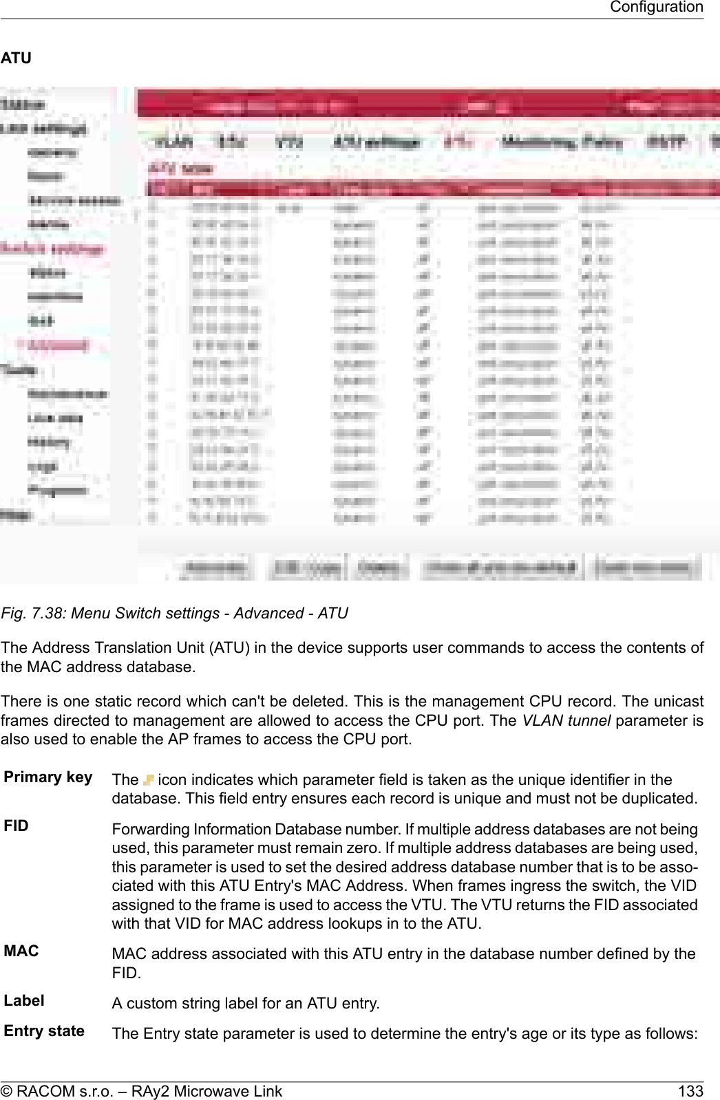
![ATU settingsFig. 7.37: Menu Switch settings - Advanced - ATU settingsSetup of ATU (Address Translation Unit) table related parameters.Agingtimeout [s] ATU age time. This value determines the time that each ATU Entry remains valid inthe database, since its last access as a source address, before being purged.The default value is 330 seconds.The minimum age time is 15 seconds.The maximum age time is 3825 seconds (almost 64 minutes).If the Age Time is set to 0 the Aging function is disabled and all learned addresseswill remain in the database forever.RAy2 Microwave Link – © RACOM s.r.o.128Configuration](https://usermanual.wiki/Racom/RAY2-24/User-Guide-2944903-Page-128.png)
![Set SA filtering to disabled or drop on unlock (PORT-0x04:14 SAFiltering[0]=0)Safe procedure:Disable or block the ports (PORT-04.1 PortState[1]=0).Flush all non-static adresses in the ATU.Define the desired limit for the ports.Re-enable the ports.SA priorityoverride When any other than "none" mode is selected, SA ATU priority overrides can occuron this port. An SA ATU priority override occurs when the source address of a frameresults in an ATU hit where the SA's MAC address returns an EntryState that indicatesPriority Override. When this happens three forms of priority overrides are possible(other than none):Normal frame priority processing is active.nonePRI value assigned to the frame's SA (the MAC priority field in theATU database) is used to overwrite the frame's previously determinedframeframe priority (FPri). If the frame egresses, the tagged priority in theframe will be this new PRI value.The two upper bits of the PRI value assigned to the frame's SA (theMAC priority field in the ATU database) are used to overwrite thequeueframe's previously determined queue priority (QPri). The QPri is usedinternally to map the frame to one of the egress queues inside theswitch. QPri override will not affect the contents of the frame in anyway.Both above overrides take effect on the frameframe+queueThe SA ATU Priority Override has a higher priority than the port's Default Priority, theframe's IEEE and/or IP priorities and the VTU Priority Override. The priority determinedby the frame's SA can however be overridden, by the frame's DA Priority Override.DA priorityoverride When any other than none mode is selected, the DA ATU priority overrides can occuron this port. A DA ATU priority override occurs when the source address of a frameresults in an ATU hit where the DA's MAC address returns an EntryState that indicatesPriority Override. When this occurs three forms of priority overrides are possible(other than none):Normal frame priority processing is active.nonePRI value assigned to the frame's DA (the MAC priority field in theATU database) is used to overwrite the frame's previously determinedframeframe priority (FPri). If the frame egresses the tagged priority in theframe will be the new PRI value.The two upper bits of the PRI value assigned to the frame's DA (theMAC priority field in the ATU database) are used to overwrite thequeueframe's previously determined queue priority (QPri). The QPri is usedinternally to map the frame to one of the egress queues inside theswitch. QPri override will not affect the contents of the frame in anyway.Both of the above overrides take place on the frameframe+queueThe DA ATU Priority Override has the highest priority over the port's Default Priority,the frame's IEEE and/or IP priorities, the VTU Priority Override and the SA PriorityOverride.131© RACOM s.r.o. – RAy2 Microwave LinkConfiguration](https://usermanual.wiki/Racom/RAY2-24/User-Guide-2944903-Page-131.png)
![RSTPFig. 7.41: Menu Switch settings - Advanced - RSTPThe Rapid Spanning Tree Protocol (RSTP) is a network protocol that ensures a loop-free topology forany bridged Ethernet local area network. The basic function of RSTP is to prevent bridge loops andthe broadcast radiation that results from them. Spanning Tree Protocol also allows network design toinclude spare (redundant) links to provide automatic backup paths if an active link fails, without thedanger of bridge loops, or the need for manual enabling/disabling of these backup links.RSTP enable When RSTP is enabled, the bridge is created and RSTP service is initiated. Shouldthe RAy2 unit be connected via two Etherent cables (using Eth1 and Eth2 ports), theactive participation of the RSTP protocol may be necessary. If the parameter is notenabled, the RAy2 unit transfers the BPDU frames transparently.NOTE: To enable proper RSTP functionality, these switch parameters has to be set:Switch settings / Interface / Port advanced / Frame mode / p5 CPU: "ether typeDSA"Switch settings / Interface / Port advanced / Ether type / p5 CPU: "0xDADA"Switch settings / Advanced / ATU settings / Reserved multicast to CPU: "Enable"Bridgepriority The priority value is a number between 0 and 61440 in incremental steps of 4096,with a default value of 32768. Lower priority values are 'better'. The bridge with thelowest priority value will be elected 'root bridge'.Hello time [s] The hello time is the time between each Bridge Protocol Data Unit (BPDU) that is senton a port. Hello time is equal to 2 seconds by default.RAy2 Microwave Link – © RACOM s.r.o.138Configuration](https://usermanual.wiki/Racom/RAY2-24/User-Guide-2944903-Page-138.png)
![Max age [s] The max age timer controls the maximum length of time that passes before a bridgeport saves its configuration BPDU information. This time is set to 20 sec by default.Forwarddelay [s] The forward delay is the time that is spent in the listening and learning state. This timeis equal to 15 sec by default.Algorithm This parameter sets the bridge's spanning tree algorithm to operate in normal (RSTP)or force it to operate in slow (STP) mode. In normal mode, RSTP reverts back to STPon ports where it sees other hosts operating in STP mode.Port name Identification of the internal switch port. The switch ports are connected to an externalport or to an internal device (radio modem, management CPU).The external port (with RJ45 interface) labeled "ETH1+POE". Port 2.The external port (with SFP interface) labeled "ETH2". Port 4.The internal port to management CPU. It is physical port number 5.The internal port to radio modem, i.e. link to the peer unit. Port 6.Eth1Eth2CPUAirPort priority The ports' priority value is a number between 0 and 240 in increments of 16, with adefault value of 128.Path cost The Path cost can be set automatically or manually. Entering the value of zero setsthis parameter automatically. The automatic setup is based on link speed.Edge Selecting the checkbox sets the port as an "edge" port. If a port is an edge port it isassumed to be a leaf link in the graph, not connected to any other bridges. Receivingany STP BPDU's on a port configured as an edge port temporarily overrides edgeport behaviour for the port.MAC address The ports' default MAC addresses are the same as the MAC address of the RAy2unit.139© RACOM s.r.o. – RAy2 Microwave LinkConfiguration](https://usermanual.wiki/Racom/RAY2-24/User-Guide-2944903-Page-139.png)

![Feature keysFig. 7.44: Menu Tools - Feature keysThe sub-set of RAy parameters is affected by use of Feature keys.The feature keys limiting data transfer speed [Mbps] are now available. Speed of the transferred datais determined by a combination of the radio channel bandwidth (parameter Bandwidth [MHz]) andmodulation order (parameter TX modulation). The Feature key limiting the data transfer speed enablesonly certain combinations of the channel bandwidth and modulation order to get the data transfer speedaccording to the Feature key. The data transfer speed is typically slightly higher than declared.When installed, the Feature key is activated after the unit restart. The unit can be restarted using theTools – Maintenance – Restart. Choose the Restart mode – warm.Feature Name of the function controlled by the Feature key.Here are listed the keys used in both units. Feature keys of the Peer unit only, aredisplayed. They can be neither added, nor deleted. To be able to manipulate theFeature keys, it is necessary to access directly the management system of therelevant unit - use the IP address of the relevant unit.Limit The numeric value set by the key.Remove The specific Feature key can be deleted using the Delete button. The parameterscontrolled by this Feature key are reset to their default values after the unit restart.NOTE: The link radio parameters can be changed subsequently (e.g. to a differentoperating frequency)!Upload Feature keys are installed into the unit from the binary files.NOTE: Use the file as it is (do not unpack).Open file upload - Dialog for the Feature key binary file selection is open.145© RACOM s.r.o. – RAy2 Microwave LinkConfiguration](https://usermanual.wiki/Racom/RAY2-24/User-Guide-2944903-Page-145.png)
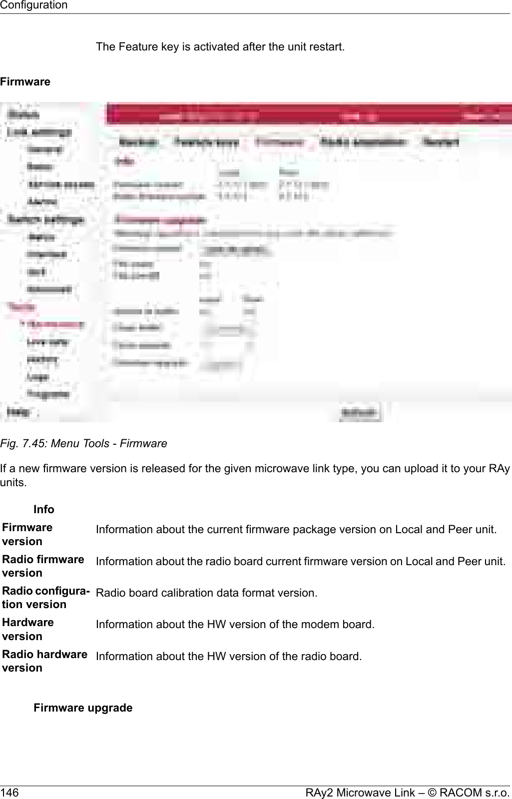
![Firmware upload Open file upload - opens a dialog for uploading firmware package to the unit buffer.Only after firmware has been prepared in the buffer, can you perform the actualupgrade.NOTE: Use the file as it is (do not unpack).File name Name of the uploaded firmware file.File size [B] Size of the uploaded firmware file.Version in buffer Information about firmware version prepared in the buffer for installation into theunit (Local, Peer). This firmware must first be prepared in the Firmware uploadsection (see above).Clean buffer You can use the Clean buffer button to delete prepared firmware package in thebuffer.Force upgrade Force mode blocks all safety and compatibility checks and probably bricks yourunit.You should not use force mode until instructed to do so by the technical support.Upgrade Use the Upgrade button to perform the firmware installation.WarningInstalling the firmware takes several minutes (about 3 minutes). Duringthis time, transmission of user data is interrupted. Do not interrupt thepower supply during firmware installation!147© RACOM s.r.o. – RAy2 Microwave LinkConfiguration](https://usermanual.wiki/Racom/RAY2-24/User-Guide-2944903-Page-147.png)
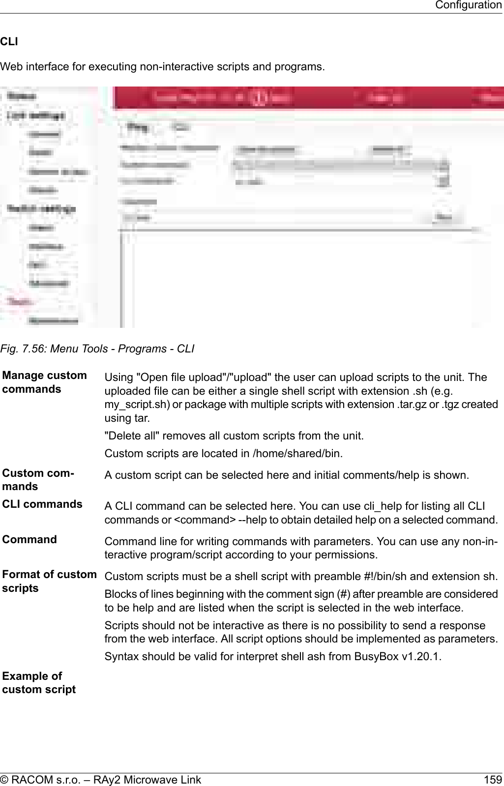
![7.6.5. ProgramsPingThe Ping tool allows sending ICMP pings to a selected addressFig. 7.55: Menu Tools - Programs - PingStart the test by clicking on Send. The result is displayed in the text window.Destination Destination address in dotted decimal notation. The default address 127.0.0.1 isthe localhost address - i.e. the unit itself.Size [B] Length of sent data 7 to 1500 bytes, 8 bytes of the header will be added.Count Number of sent pings.The period for sending pings is constant: 1000 ms.RAy2 Microwave Link – © RACOM s.r.o.158Configuration](https://usermanual.wiki/Racom/RAY2-24/User-Guide-2944903-Page-158.png)
![#!/bin/sh#script checkes if service with the same name or vid already exists#if not creates a new entry in VTU with given VID## input parameters:# service_name - name of the new service# VID - vid of the new service## return values:# 0 - ok# 3 - bad parameter# 5 - service already exists# 6 - there already exists an entry with given VID# 42 - other errorD42_NAME="$1"D42_VID="$2"D42N="service_data42"error(){echo "$D42N: Error: $*" >&2}info(){echo "$D42N: $*" >&2}die(){error "$*"exit 42 #error}# basic check if not emptyif [ -z "$D42_NAME" ]; thenerror "Bad service name"exit 3fiif [ -z "$D42_VID" ]; thenerror "Bad service VID"exit 3fiD42_FOUND=$(cli_nw_get --vtu all | grep "$D42_NAME")if [ -n "$D42_FOUND" ]; thenerror "Service(s) with name $D42_NAME found"echo $D42_FOUNDexit 5fiRAy2 Microwave Link – © RACOM s.r.o.160Configuration](https://usermanual.wiki/Racom/RAY2-24/User-Guide-2944903-Page-160.png)
![D42_VALID=$(cli_nw_get --vtu "$D42_VID" | sed -n 's/^valid=\(.\+\)$/\1/p')if [ "pre_$D42_VALID" = "pre_true" ]; thenerror "VID $D42_VID is used"cli_nw_get --vtu "$D42_VID"exit 6fiD42_VALID=$(cli_nw_get --stu 1 | sed -n 's/^valid=\(.\+\)$/\1/p')if [ "pre_$D42_VALID" = "pre_false" ]; theninfo "Creating STU entry with SID=1"cli_nw_set --stu 1 'label="D42_auto", port_state=["disabled", "disabled", ►"forwarding", "disabled", "disabled", "forwarding", "forwarding"]'if [ $? -ne 0 ]; thendie "Failed to create STU entry"fifiinfo "Creating service \"$D42_NAME\" with VID=$D42_VID"cli_nw_set --vtu "$D42_VID" label="$D42_NAME" 'fid=0, sid=1, pri_override=true, priority=5, ►policy=false, member_tag=["unmodify", "unmodify", "tag", "unmodify", "not_member", ►"not_member", "unmodify"]'if [ $? -ne 0 ]; thendie "Failed to create service \"$D42_NAME\" with VID=$D42_VID"fi161© RACOM s.r.o. – RAy2 Microwave LinkConfiguration](https://usermanual.wiki/Racom/RAY2-24/User-Guide-2944903-Page-161.png)
![• Entering more parameters in both unitscli_cnf_set -t b RADIO_TX_CHAN=17128000 PEER_RADIO_RX_CHAN=17128000• Put parameters containing spaces in quotation marks:cli_time_set -t b -T '2012-11-27 10:55:00'Set time in both units8.2.1. SSH keys• Generation using ssh-keygen[user@laptop ~]$ ssh-keygen -t dsa -f usr_ssh_keyUses working directory to save private usr_ssh_key and public part of the key usr_ssh_key.pub• Copying the key into the RAy2 unit[user@laptop ~]$ scp usr_ssh_key.pub admin@192.168.141.202:/tmpThe public part of the key is written to the folder /tmp• Installation of key in RAy2 unitCLI(admin):/rrusrhomes/admin$ cli_user_authkey -c a -k /tmp/usr_ssh_key.pub• Testing access to RAy2 unit using SSH key[user@laptop ~]$ ssh -i usr_ssh_key admin@192.168.141.2028.2.2. Scripts• Script example with access using key[user@laptop ~]$ ssh -i usr_ssh_key admin@192.168.141.202"source /etc/profile;cli_info_link;echo \$?;cli_cnf_show | grep TX_PWR;echo $?"Warning: Permanently added '192.168.141.202' (DSA) to the list of known hosts.cli_info_link: Link status: up0RADIO_TX_PWR=40[user@laptop ~]$• The script contains:environment settingssource /etc/profile;query for link statuscli_info_link;reading return valueecho \$?;query for radio powercli_cnf_show | grep TX_PWR;reading return valueecho \$?return valuecli_info_link: Link status:upOK command0power +4 dBmRADIO_TX_PWR=4OK command0167© RACOM s.r.o. – RAy2 Microwave LinkCommand Line Interface](https://usermanual.wiki/Racom/RAY2-24/User-Guide-2944903-Page-167.png)
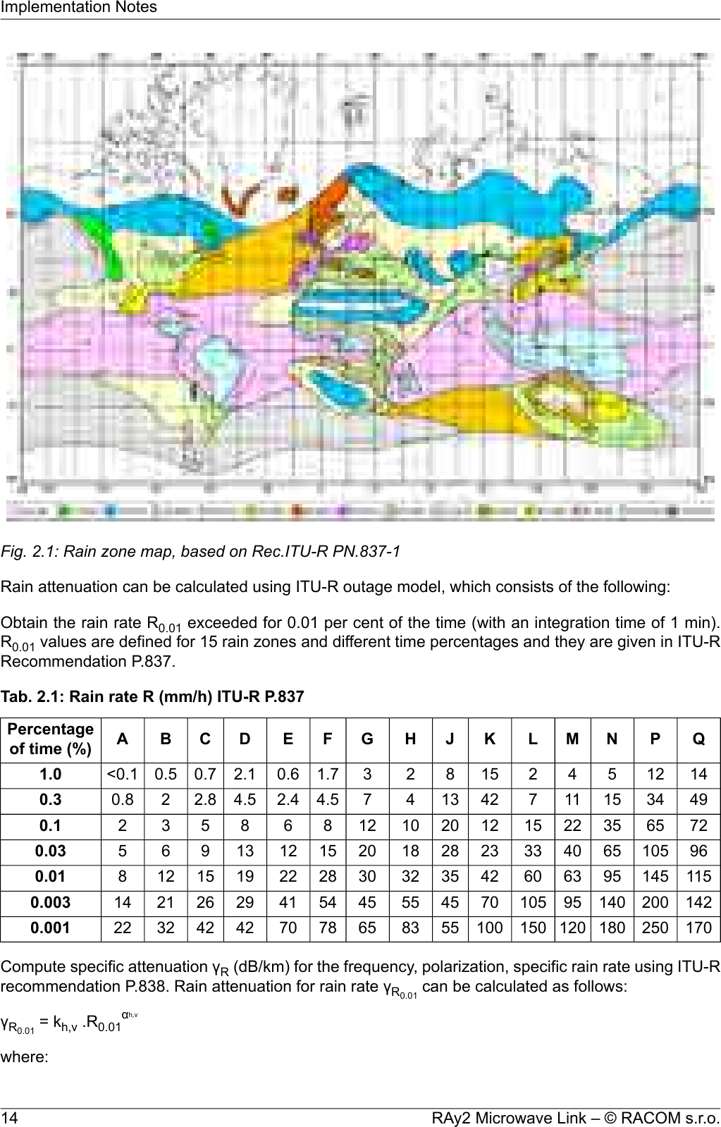
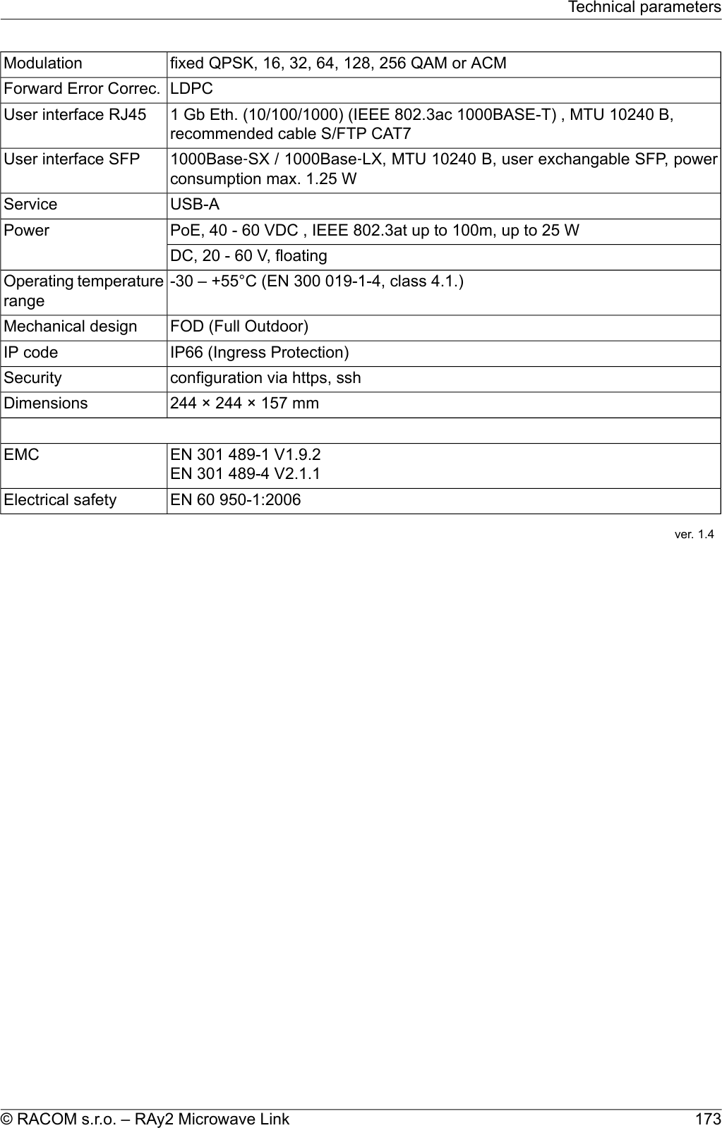
![10. Technical parameters10.1. General parameters10.1.1. Technical parameters overviewTab. 10.1: Technical parametersRAy2-24RAy2-17RAy2-11RAy2-10Type24.0 – 24.2517.1 – 17.3A:A:Band [GHz],sub-bands A,B..10.695 – 11.46010.30 – 10.59B:B:10.935 – 11.69510.125 – 10.675One universal unitUnit L and UODU initsoptionalmin 60optionalmin 60490, 530any combinationL and U unitsDuplexspacing [MHz]3.5, 7, 14, 28,40, 50, 563.5, 7, 14, 28,40, 50, 561.75, 3.5, 7, 14, 28,30, 40, 561.75, 3.5, 7, 14, 20,28, 56Channel spacingCS [MHz]detaildetaildetaildetailChannel freq.4.9 – 3604.9 – 3602.5 – 3602.5 – 360User speed[Mbps] detaildetaildetaildetail81 (64B/359Mbps),234 (1518B/359Mbps)Latency [μs]-96 (4.9 Mbps)-65 (340 Mbps)-96 (4.9 Mbps)-66 (340 Mbps)-99 (2.5 Mbps)-67 (340 Mbps)-100 (2.5 Mbps)-67 (340 Mbps)Sensitivity,BER 10-6 [dBm] detaildetaildetaildetail-30 – +10-25 – +5-15 – +24 (QPSK)-15 – +19 (256QAM)-10 – +13 (QPSK)-10 – +8 (256QAM)Output Power[dBm]yesyesyesyesATPC232121 – 2921Consumption [W]2.52.52.82.8Weight [kg]EN 300 440-2 V1.4.1EN 302 217-2-2 V2.1.1Radio param.ver. 2.11RAy2 Microwave Link – © RACOM s.r.o.172Technical parameters](https://usermanual.wiki/Racom/RAY2-24/User-Guide-2944903-Page-172.png)
![10.1.2. Link speedNominal link speedUser data rate [Mbps]RAy2 - xx56MHz TO56MHz50MHz40MHz28 / 30MHz20MHz14MHz7MHz3.5MHz1.75MHzModula-tion ACCPACCPACCPACCPACAPACCPACCPACCPACCPACCPACCP85.872.966.350.138.336.822.819.98.54.92.5QPSK169.9160.2145.6110.084.180.950.238.817.29.64.916-QAM206.2202.7184.2139.2106.4102.463.549.122.112.16.332-QAM268.1256.9233.6176.5135.0129.880.562.329.714.37.464-QAM309.0303.7276.1211.4161.7155.596.473.634.717.28.9128-QAM358.9337.7320.6232.1185.2170.7110.481.240.719.7256-QAMver. 2.7Link speed according to RFC 2544valuesLink speed [Mbps] for frames 64 - 1518 BRAy2 - xx minimummaximum56MHzTO56 MHz40 MHz28 / 30 MHz14 MHz7 MHz3.5 MHz1.75 MHzModulation/ CS ACCPACCPACCPACAPACCPACCPACCPACCPACCP76.185.264.772.344.349.633.837.932.636.517.619.67.58.34.24.62.12.3QPSK150.7168.6142.1159.097.5109.274.683.471.780.234.338.515.117.08.49.34.34.816-QAM182.9204.8179.9201.3123.4138.294.3105.690.7101.543.448.619.621.810.611.95.46.032-QAM238.1266.4228.0255.1156.6175.3119.7133.9115.1128.855.261.726.129.312.614.16.57.264-QAM274.5307.1269.7301.6187.7209.9143.5160.5138.0154.565.273.030.734.315.117.07.88.7128-QAM318.8356.5300.2335.8206.1230.7164.4184.0151.5169.571.980.536.140.317.419.4256-QAMver. 1.1RAy2 Microwave Link – © RACOM s.r.o.174Technical parameters](https://usermanual.wiki/Racom/RAY2-24/User-Guide-2944903-Page-174.png)
![ACM switching according to SNR stateSNR degrade / improve [dB]RAy2 - xx56MHz TO56MHz50MHz40MHz28MHz20MHz14MHz7MHz3.5MHz1.75MHzModulation/ CS ACCPACCPACCPACCPACCPACCPACCPACCPACCPACCP-19.0-19.0-19.0-19.0-19.0-19.0-19.0-19.0-19.0-19.0QPSK17.023.017.023.017.023.017.023.017.023.017.023.017.023.017.023.017.023.017.023.016-QAM20.526.020.026.020.026.020.026.020.026.020.026.020.026.020.026.020.026.020.026.032-QAM24.528.523.028.523.028.523.028.523.028.523.028.523.028.523.028.523.028.523.028.564-QAM27.031.025.030.525.030.525.030.525.030.525.030.525.030.525.030.525.031.525.0-128-QAM29.0-28.0-28.0-28.0-28.0-28.0-28.0-28.0-28.5---256-QAMver. 1.2FCC commentChoice of modulation must respect the requirements of Section 11.9, “FCC authorization of transmitters”.175© RACOM s.r.o. – RAy2 Microwave LinkTechnical parameters](https://usermanual.wiki/Racom/RAY2-24/User-Guide-2944903-Page-175.png)
![10.2. Nominal frequency tables description1) TX channel nominal frequenciesBand 10.7 – 11.7 GHz,3)duplex frequency 490 MHz4)2) CEPT 12-06 Annex C 5)6)(Freq.table: rcinfo11_A_490, rcinfo11_A_490_n)7) (Freq.table: rcinfo11_B_490, rcinfo11_B_490_n)Ch.No.Lower [MHz] Upper [MHz]Ch.No.Lower [MHz] Upper [MHz]18) 10755 9) 11245 10) 7 10995 114852 10795 11285 8 11035 115253 10835 11325 9 11075 115654 10875 11365 10 11115 116055 10915 11405 11 11155 11645ver. 1.0 11) RAy11 – xA , RAy11 – xB Bandwidth: 56 MHz (CS 80)A sub-band B sub-band 1) The respective RAy unit name. The letter “x” stands for “L” or “U” (Lower or Upper band unit).Example: “RAy11-xA” means both “RAy11-LA” and “RAy11-UA” units. See overview table fordetails.NOTE: The optional last figure in the unit name (e.g. RAy11-LA-2) denotes number of Ethernetports and it is not relevant for the Nominal frequency tables.2) The respective channel set (nominal frequencies) name in the Ray unit configuration interface(see Configuration, item “Bandwith [MHz]”. In addition to the bandwith definition, the name maycontain additional text which defines the respective alternative of channel plan. Examples:• “Bandwith: 40 MHz (ITU)” means that the nominal frequencies in the table follow the recom-mendation ITU-R F.387 rec.1.2. for 40 MHz bandwith, see also the note 5) below.•“Bandwith: 40 MHz (ACMA)” means that the table describes the 40 MHz channel plan definedby ITU-R F.387 rec. 1.1. (b), applied e.g. in Australia.3) The complete frequency range (approx.)4) Duplex spacing – the frequency difference between the Upper and Lower channels in a duplexpair.Optional: The minimum and the maximal duplex spacing used in the table of frequencies.5) The name of standard or recommendation defining the respective channel plan.6) Name of the sub-band defined by channels in the table.7) Name of the “Frequency table” containing the channel set described (see Configuration, item"Frequency tables").8) The channel number according to RAy unit configuration interface (see Configuration, item “TXchannel [GHz]”).9) The nominal TX frequency of the Lower-band channel10) The nominal TX frequency of the Upper-band channel.11) Table version.RAy2 Microwave Link – © RACOM s.r.o.176Technical parameters](https://usermanual.wiki/Racom/RAY2-24/User-Guide-2944903-Page-176.png)
![10.3. RAy2-10 parameters10.3.1. Upper/Lower LimitsTX powerRAy2-10-xA,RAy2-10-xBMaxMinModulation [dBm][dBm]13-10QPSK11-1016-QAM11-1032-QAM10-1064-QAM9-10128-QAM8-10256-QAMver. 1.2Duplex spacingRAy2-10-xA,RAy2-10-xB[MHz]Sub-bandAll combinations of channelsAAll combinations of channelsBver. 2.5Sub-band RangeRAy2-10-xA,RAy2-10-xBUnit UUnit LSub-band[MHz][MHz]10.47010.300minA10.59010.420max10.47510.125minB11.67510.325maxver. 1.1177© RACOM s.r.o. – RAy2 Microwave LinkTechnical parameters](https://usermanual.wiki/Racom/RAY2-24/User-Guide-2944903-Page-177.png)
![10.3.2. Radio parametersChannel spacing 1.75 MHz; ACCP operationRAy2-10Adjacent channel SelectivityCo-channel rejectionRSS / SNR forBER 10-6UserBitRateRawBitRateModula-tion3 dB1 dB3 dB1 dBdeclared / limitdeclared / limitdeclared / limitdeclared / limitSNRRSS[dB][dB][dB][dB][dB][dBm][Mbps][-]-4/-140/-1219/1223/179.5-1002.53.1QPSK-7/-13-3/-1126.5/2030/2215.0-925.06.316-QAM-7/-12-3/-1026.5/2230/2419.0-886.37.832-QAM-7/-10-3/-926.5/2630/2920.5-877.49.464-QAM-9/-9-5/-529/2933/3023.5-848.911.0128-QAMver. 2.4Channel spacing 3.5 MHz; ACCP operationRAy2-10Adjacent channel SelectivityCo-channel rejectionRSS / SNR forBER 10-6UserBitRateRawBitRateModula-tion3 dB1 dB3 dB1 dBdeclared / limitdeclared / limitdeclared / limitdeclared / limitSNRRSS[dB][dB][dB][dB][dB][dBm][Mbps][-]-4/-160/-1419/1223/159.5-964.96QPSK-7/-15-3/-1326.5/2030/2215.0-899.61216-QAM-7/-14-3/-1226.5/2230/2418.5-8612.11532-QAM-7/-12-3/-1126.5/2630/2920.5-8514.31864-QAM-7/-8-3/-926.5/2630/3023.5-8317.221128-QAM-4/-60/-736/3140/3326.0-8019.724256-QAMver. 2.4Channel spacing 7 MHz; ACCP operationRAy2-10Adjacent channel SelectivityCo-channel rejectionRSS / SNR forBER 10-6UserBitRateRawBitRateModula-tion3 dB1 dB3 dB1 dBdeclared / limitdeclared / limitdeclared / limitdeclared / limitSNRRSS[dB][dB][dB][dB][dB][dBm][Mbps][-]-4/-220/-2019/1223/158.5-948.512QPSK-7/-19-3/-1826.5/2030/2215.0-8717.22416-QAM-9/-18-5/-1629/2233/2418.5-8422.13032-QAM-7/-16-3/-1430/2634/2921.5-8029.73664-QAM-6/-14-2/-1233/3037/3225.0-7834.742128-QAM-4/-120/-1036/3140/3326.0-7639.749256-QAMver. 2.4RAy2 Microwave Link – © RACOM s.r.o.178Technical parameters](https://usermanual.wiki/Racom/RAY2-24/User-Guide-2944903-Page-178.png)
![Channel spacing 14 MHz; ACCP operationRAy2-10Adjacent channel SelectivityCo-channel rejectionRSS / SNR forBER 10-6UserBitRateRawBitRateModula-tion3 dB1 dB3 dB1 dBdeclared / limitdeclared / limitdeclared / limitdeclared / limitSNRRSS[dB][dB][dB][dB][dB][dBm][Mbps][-]-4/-230/-2119/1223/148.5-9219.924QPSK-7/-21-3/-1926.5/1830/2015.0-8538.84816-QAM-9/-19-5/-1729/2333/2618.5-8149.16032-QAM-7/-17-3/-1430/2634/2821.5-7862.37264-QAM-6/-14-2/-1233/2837/3025.0-7573.684128-QAM-4/-120/-1036/3140/3328.0-7381.296256-QAMver. 2.4Channel spacing 20 MHz; ACCP operationRAy2-10Adjacent channel SelectivityCo-channel rejectionRSS / SNR forBER 10-6UserBitRateRawBitRateModula-tion3 dB1 dB3 dB1 dBdeclared / limitdeclared / limitdeclared / limitdeclared / limitSNRRSS[dB][dB][dB][dB][dB][dBm][Mbps][-]-4/-230/-2119/1223/148.5-9122.831QPSK-12/-21-8/-1926.5/1830/2015.0-8450.26216-QAM-12/-19-8/-1726.5/2330/2618.5-8063.577.532-QAM-12/-17-8/-1426.5/2630/2821.5-7780.59364-QAM-6/-14-2/-1233/2837/3025.0-7396.4108.5128QAM-4/-120/-1036/3140/3328.0-71110.4124256-QAMver. 2.4Channel spacing 28 / 30 MHz; ACCP operationRAy2-10Adjacent channel SelectivityCo-channel rejectionRSS / SNR forBER 10-6UserBitRateRawBitRateModula-tion3 dB1 dB3 dB1 dBdeclared / limitdeclared / limitdeclared / limitdeclared / limitSNRRSS[dB][dB][dB][dB][dB][dBm][Mbps][-]-4/-230/-2119/1023/127.5-9036.850QPSK-7/-20-3/-1826.5/1830/2015.0-8280.910016-QAM-9/-19-5/-1629/2233/2418.5-78102.412532-QAM-7/-15-3/-1230/2634/2821.5-75129.815064-QAM-8/-12-5/-932/2835/3025.0-71155.5175128QAM-4/-90/-636/3140/3326.5-69170.7200256-QAMver. 2.4179© RACOM s.r.o. – RAy2 Microwave LinkTechnical parameters](https://usermanual.wiki/Racom/RAY2-24/User-Guide-2944903-Page-179.png)
![Channel spacing 28 / 30 MHz; ACAP operationRAy2-10Adjacent channel SelectivityCo-channel rejectionRSS / SNR forBER 10-6UserBitRateRawBitRateModula-tion3 dB1 dB3 dB1 dBdeclared / limitdeclared / limitdeclared / limitdeclared / limitSNRRSS[dB][dB][dB][dB][dB][dBm][Mbps][-]-4/-170/-1519/1023/127.5-88.538.352QPSK-7/-14-3/-1226.5/1830/2015.0-81.584.110416-QAM-9/-13-5/-1029/2233/2418.5-77.5106.413032-QAM1/-94/-630/2634/2821.5-74.5135.015664-QAM7/-610/-336/2840/3025.0-70.5161.7182128QAM6/-310/039/3143/3326.5-67.5185.2208256-QAMver. 2.4Channel spacing 56 MHz; ACCP operationRAy2-10Adjacent channel SelectivityCo-channel rejectionRSS / SNR forBER 10-6UserBitRateRawBitRateModula-tion3 dB1 dB3 dB1 dBdeclared / limitdeclared / limitdeclared / limitdeclared / limitSNRRSS[dB][dB][dB][dB][dB][dBm][Mbps][-]-4/-280/-2619/1023/127.5-8672.999QPSK-7/-21-3/-1926.5/1730/1915.0-79160.219816-QAM-9/-17-5/-1529/2233/2418.5-75202.7247.532-QAM-7/-16-3/-1430/2534/2721.5-72256.929764-QAM-8/-12-5/-1032/2835/3025.0-68303.7346.5128QAM-4/-100/-836/3040/3326.5-66337.7396256-QAMver. 2.4Channel spacing 56 MHz TO; ACCP operationRAy2-10Adjacent channel SelectivityCo-channel rejectionRSS / SNR forBER 10-6UserBitRateRawBitRateModula-tion3 dB1 dB3 dB1 dBdeclared / limitdeclared / limitdeclared / limitdeclared / limitSNRRSS[dB][dB][dB][dB][dB][dBm][Mbps][-]-4/-260/-2419/1123/1310.0-8485.899QPSK-7/-20-3/-1826.5/1830/2016.0-77169.919816-QAM-9/-15-5/-1429/2333/2519.0-73206.2247.532-QAM-7/-11-3/-930/2634/2922.5-69268.129764-QAM-8/-10-5/-832/2935/3225.5-66309.0346.5128QAM-4/-80/-739/3243/3527.5-63358.9396256-QAMver. 2.4RAy2 Microwave Link – © RACOM s.r.o.180Technical parameters](https://usermanual.wiki/Racom/RAY2-24/User-Guide-2944903-Page-180.png)
![10.3.3. Nominal frequencies, band 10.30 – 10.59 GHzTX channel nominal frequenciesBand 10.30 – 10.59 GHz default duplex 168 MHz Bandwidth: 1.75 MHzChannel arrangements based on 7 MHz channelsduplex range 57.75 – 285.25 MHz( Freq.table: rcinfo10_A_default:6 )Ch.No. Lower [MHz] Upper [MHz] Ch.No. Lower [MHz] Upper [MHz]1 10301.8752 10303.6253 10305.3754 10307.1255 10308.875 10476.875 37 10364.875 10532.8756 10310.625 10478.625 38 10366.625 10534.6257 10312.375 10480.375 39 10368.375 10536.3758 10314.125 10482.125 40 10370.125 10538.1259 10315.875 10483.875 41 10371.875 10539.87510 10317.625 10485.625 42 10373.625 10541.62511 10319.375 10487.375 43 10375.375 10543.37512 10321.125 10489.125 44 10377.125 10545.12513 10322.875 10490.875 45 10378.875 10546.87514 10324.625 10492.625 46 10380.625 10548.62515 10326.375 10494.375 47 10382.375 10550.37516 10328.125 10496.125 48 10384.125 10552.12517 10329.875 10497.875 49 10385.875 10553.87518 10331.625 10499.625 50 10387.625 10555.62519 10333.375 10501.375 51 10389.375 10557.37520 10335.125 10503.125 52 10391.125 10559.12521 10336.875 10504.875 53 10392.875 10560.87522 10338.625 10506.625 54 10394.625 10562.62523 10340.375 10508.375 55 10396.375 10564.37524 10342.125 10510.125 56 10398.125 10566.12525 10343.875 10511.875 57 10399.875 10567.87526 10345.625 10513.625 58 10401.625 10569.62527 10347.375 10515.375 59 10403.375 10571.37528 10349.125 10517.125 60 10405.125 10573.12529 10350.875 10518.875 61 10406.875 10574.87530 10352.625 10520.625 62 10408.625 10576.62531 10354.375 10522.375 63 10410.375 10578.37532 10356.125 10524.125 64 10412.125 10580.12533 10357.875 10525.875 65 10413.875 10581.87534 10359.625 10527.625 66 10415.625 10583.62535 10361.375 10529.375 67 10417.375 10585.37536 10363.125 10531.125 68 10419.125 10587.12537 10364.875 10532.87538 10366.625 10534.625 ver. 2.0 RAy2-10 – xAA sub-band 181© RACOM s.r.o. – RAy2 Microwave LinkTechnical parameters](https://usermanual.wiki/Racom/RAY2-24/User-Guide-2944903-Page-181.png)
![TX channel nominal frequenciesBand 10.30 – 10.59 GHz default duplex 168 MHz Bandwidth: 3.5 MHzChannel arrangements based on 7 MHz channelsduplex range 59.5 – 283.5 MHz( Freq.table: rcinfo10_A_default:6 )Ch.No. Lower [MHz] Upper [MHz] Ch.No. Lower [MHz] Upper [MHz]1 10302.752 10306.253 10309.75 10477.75 19 10365.75 10533.754 10313.25 10481.25 20 10369.25 10537.255 10316.75 10484.75 21 10372.75 10540.756 10320.25 10488.25 22 10376.25 10544.257 10323.75 10491.75 23 10379.75 10547.758 10327.25 10495.25 24 10383.25 10551.259 10330.75 10498.75 25 10386.75 10554.7510 10334.25 10502.25 26 10390.25 10558.2511 10337.75 10505.75 27 10393.75 10561.7512 10341.25 10509.25 28 10397.25 10565.2513 10344.75 10512.75 29 10400.75 10568.7514 10348.25 10516.25 30 10404.25 10572.2515 10351.75 10519.75 31 10407.75 10575.7516 10355.25 10523.25 32 10411.25 10579.2517 10358.75 10526.75 33 10414.75 10582.7518 10362.25 10530.25 34 10418.25 10586.2519 10365.75 10533.7520 10369.25 10537.25 ver. 2.0 RAy2-10 – xAA sub-band TX channel nominal frequenciesBand 10.30 – 10.59 GHz default duplex 168 MHz Bandwidth: 7 MHz VO-R/14/12.2012-17 duplex range 63 – 280 MHz( Freq.table: rcinfo10_A_default:6 )Ch.No. Lower [MHz] Upper [MHz] Ch.No. Lower [MHz] Upper [MHz]1 10304.52 10308.03 10311.5 10479.5 11 10367.5 10535.54 10318.5 10486.5 12 10374.5 10542.55 10325.5 10493.5 13 10381.5 10549.56 10332.5 10500.5 14 10388.5 10556.57 10339.5 10507.5 15 10395.5 10563.58 10346.5 10514.5 16 10402.5 10570.59 10353.5 10521.5 17 10409.5 10577.510 10360.5 10528.5 18 10416.5 10584.511 10367.5 10535.512 10374.5 10542.5 ver. 2.0 RAy2-10 – xAA sub-band RAy2 Microwave Link – © RACOM s.r.o.182Technical parameters](https://usermanual.wiki/Racom/RAY2-24/User-Guide-2944903-Page-182.png)
![TX channel nominal frequenciesBand 10.30 – 10.59 GHz default duplex 168 MHz Bandwidth: 14 MHz VO-R/14/12.2012-17 duplex range 70 – 273 MHz( Freq.table: rcinfo10_A_default:6 )Ch.No. Lower [MHz] Upper [MHz] Ch.No. Lower [MHz] Upper [MHz]1 103082 10315 10483 6 10371 105393 10329 10497 7 10385 105534 10343 10511 8 10399 105675 10357 10525 9 10413 105816 10371 105397 10385 10553 ver. 2.0 RAy2-10 – xAA sub-band TX channel nominal frequenciesBand 10.30 – 10.59 GHz default duplex 168 MHz Bandwidth: 28 MHz VO-R/14/12.2012-17 duplex range 84 – 252 MHz( Freq.table: rcinfo10_A_default:6 )Ch.No. Lower [MHz] Upper [MHz] Ch.No. Lower [MHz] Upper [MHz]1 10322 10490 3 10378 105462 10350 10518 4 10406 105743 10378 105464 10406 10574 ver. 2.0 RAy2-10 – xAA sub-band TX channel nominal frequenciesBand 10.30 – 10.59 GHz default duplex 168 MHz Bandwidth: 56 MHzChannel arrangements based on 7 MHz channelsduplex range 112 – 224 MHz( Freq.table: rcinfo10_A_default:6 )Ch.No. Lower [MHz] Upper [MHz] Ch.No. Lower [MHz] Upper [MHz]1 10336 10504 2 10392 105602 10392 10560ver. 2.0 RAy2-10 – xAA sub-band 183© RACOM s.r.o. – RAy2 Microwave LinkTechnical parameters](https://usermanual.wiki/Racom/RAY2-24/User-Guide-2944903-Page-183.png)
![10.3.4. Nominal frequencies, band 10.15 – 10.65 GHzTX channel nominal frequenciesBand 10.15 – 10.65 GHz, duplex spacing 350 MHz Bandwidth: 1.75 MHz Based on 3.5 MHz channels( Freq.table: rcinfo10_B_default:5 )Ch.No. Lower [MHz] Upper [MHz] Ch.No. Lower [MHz] Upper [MHz]1 10151.375 10501.375 43 10224.875 10574.8752 10153.125 10503.125 44 10226.625 10576.6253 10154.875 10504.875 45 10228.375 10578.3754 10156.625 10506.625 46 10230.125 10580.1255 10158.375 10508.375 47 10231.875 10581.8756 10160.125 10510.125 48 10233.625 10583.6257 10161.875 10511.875 49 10235.375 10585.3758 10163.625 10513.625 50 10237.125 10587.1259 10165.375 10515.375 51 10238.875 10588.87510 10167.125 10517.125 52 10240.625 10590.62511 10168.875 10518.875 53 10242.375 10592.37512 10170.625 10520.625 54 10244.125 10594.12513 10172.375 10522.375 55 10245.875 10595.87514 10174.125 10524.125 56 10247.625 10597.62515 10175.875 10525.875 57 10249.375 10599.37516 10177.625 10527.625 58 10251.125 10601.12517 10179.375 10529.375 59 10252.875 10602.87518 10181.125 10531.125 60 10254.625 10604.62519 10182.875 10532.875 61 10256.375 10606.37520 10184.625 10534.625 62 10258.125 10608.12521 10186.375 10536.375 63 10259.875 10609.87522 10188.125 10538.125 64 10261.625 10611.62523 10189.875 10539.875 65 10263.375 10613.37524 10191.625 10541.625 66 10265.125 10615.12525 10193.375 10543.375 67 10266.875 10616.87526 10195.125 10545.125 68 10268.625 10618.62527 10196.875 10546.875 69 10270.375 10620.37528 10198.625 10548.625 70 10272.125 10622.12529 10200.375 10550.375 71 10273.875 10623.87530 10202.125 10552.125 72 10275.625 10625.62531 10203.875 10553.875 73 10277.375 10627.37532 10205.625 10555.625 74 10279.125 10629.12533 10207.375 10557.375 75 10280.875 10630.87534 10209.125 10559.125 76 10282.625 10632.62535 10210.875 10560.875 77 10284.375 10634.37536 10212.625 10562.625 78 10286.125 10636.12537 10214.375 10564.375 79 10287.875 10637.87538 10216.125 10566.125 80 10289.625 10639.62539 10217.875 10567.875 81 10291.375 10641.37540 10219.625 10569.625 82 10293.125 10643.12541 10221.375 10571.375 83 10294.875 10644.87542 10223.125 10573.125 84 10296.625 10646.62543 10224.875 10574.87544 10226.625 10576.625 ver. 2.0 RAy2-10 - xB B sub-band RAy2 Microwave Link – © RACOM s.r.o.184Technical parameters](https://usermanual.wiki/Racom/RAY2-24/User-Guide-2944903-Page-184.png)
![TX channel nominal frequenciesBand 10.15 – 10.65 GHz, duplex spacing 350 MHz Bandwidth: 3.5 MHz CEPT/ERC/REC 12-05 E( Freq.table: rcinfo10_B_default:5 )Ch.No. Lower [MHz] Upper [MHz] Ch.No. Lower [MHz] Upper [MHz]1 10152.25 10502.25 22 10225.75 10575.752 10155.75 10505.75 23 10229.25 10579.253 10159.25 10509.25 24 10232.75 10582.754 10162.75 10512.75 25 10236.25 10586.255 10166.25 10516.25 26 10239.75 10589.756 10169.75 10519.75 27 10243.25 10593.257 10173.25 10523.25 28 10246.75 10596.758 10176.75 10526.75 29 10250.25 10600.259 10180.25 10530.25 30 10253.75 10603.7510 10183.75 10533.75 31 10257.25 10607.2511 10187.25 10537.25 32 10260.75 10610.7512 10190.75 10540.75 33 10264.25 10614.2513 10194.25 10544.25 34 10267.75 10617.7514 10197.75 10547.75 35 10271.25 10621.2515 10201.25 10551.25 36 10274.75 10624.7516 10204.75 10554.75 37 10278.25 10628.2517 10208.25 10558.25 38 10281.75 10631.7518 10211.75 10561.75 39 10285.25 10635.2519 10215.25 10565.25 40 10288.75 10638.7520 10218.75 10568.75 41 10292.25 10642.2521 10222.25 10572.25 42 10295.75 10645.7522 10225.75 10575.7523 10229.25 10579.25 ver. 2.0 RAy2-10 - xB B sub-band TX channel nominal frequenciesBand 10.15 – 10.65 GHz, duplex spacing 350 MHz Bandwidth: 7 MHz CEPT/ERC/REC 12-05 E( Freq.table: rcinfo10_B_default:5 )Ch.No. Lower [MHz] Upper [MHz] Ch.No. Lower [MHz] Upper [MHz]1 10157.5 10507.5 11 10227.5 10577.52 10164.5 10514.5 12 10234.5 10584.53 10171.5 10521.5 13 10241.5 10591.54 10178.5 10528.5 14 10248.5 10598.55 10185.5 10535.5 15 10255.5 10605.56 10192.5 10542.5 16 10262.5 10612.57 10199.5 10549.5 17 10269.5 10619.58 10206.5 10556.5 18 10276.5 10626.59 10213.5 10563.5 19 10283.5 10633.510 10220.5 10570.5 20 10290.5 10640.511 10228 1057812 10235 10585 ver. 2.0 RAy2-10 - xB B sub-band 185© RACOM s.r.o. – RAy2 Microwave LinkTechnical parameters](https://usermanual.wiki/Racom/RAY2-24/User-Guide-2944903-Page-185.png)
![TX channel nominal frequenciesBand 10.15 – 10.65 GHz, duplex spacing 350 MHz Bandwidth: 14 MHz CEPT/ERC/REC 12-05 E + 7 MHz based channels( Freq.table: rcinfo10_B_default:5 )Ch.No. Lower [MHz] Upper [MHz] Ch.No. Lower [MHz] Upper [MHz]1 10161 10511 6 10231 105811c 10168 10518 6c 10238 105882 10175 10525 7 10245 105952c 10182 10532 7c 10252 106023 10189 10539 8 10259 106093c 10196 10546 8c 10266 106164 10203 10553 9 10273 106234c 10210 10560 9c 10280 106305 10217 10567 10 10287 106375c 10224 10574610231 105816c 10238 10588 ver. 2.0 RAy2-10 - xB B sub-band TX channel nominal frequenciesBand 10.15 – 10.65 GHz, duplex spacing 350 MHz Bandwidth: 20 MHz( Freq.table: rcinfo10_B_default:5 )Ch.No. Lower [MHz] Upper [MHz] Ch.No. Lower [MHz] Upper [MHz]1 10175 10525 4 10235 105852 10195 10545 5 10255 106053 10215 10565 6 10275 106254 10235 10585 0 0 05 10255 10605 ver. 1.0 RAy2-10 - xB B sub-band TX channel nominal frequenciesBand 10.15 – 10.65 GHz, duplex spacing 350 MHz Bandwidth: 28 MHz CEPT/ERC/REC 12-05 E( Freq.table: rcinfo10_B_default:5 )Ch.No. Lower [MHz] Upper [MHz] Ch.No. Lower [MHz] Upper [MHz]1 10168 10518 4 10252 106022 10196 10546 5 10280 106303 10224 105744 10252 106025 10280 10630 ver. 2.0 RAy2-10 - xB B sub-band RAy2 Microwave Link – © RACOM s.r.o.186Technical parameters](https://usermanual.wiki/Racom/RAY2-24/User-Guide-2944903-Page-186.png)
![TX channel nominal frequenciesBand 10.15 – 10.65 GHz, duplex spacing 350 MHz Bandwidth: 56 MHz CEPT/ERC/REC 12-05 E( Freq.table: rcinfo10_B_default:5 )Ch.No. Lower [MHz] Upper [MHz] Ch.No. Lower [MHz] Upper [MHz]1 10182 10532 3 10238 105882 10210 10560 4 10266 106163 10238 105884 10266 10616 ver. 2.0 RAy2-10 - xB B sub-band 187© RACOM s.r.o. – RAy2 Microwave LinkTechnical parameters](https://usermanual.wiki/Racom/RAY2-24/User-Guide-2944903-Page-187.png)
![10.4. RAy2-11 A,B parameters10.4.1. Upper/Lower LimitsTX powerRAy2-11-xA,RAy2-11-xBMaxMinModulation [dBm][dBm]24-15QPSK22-1516-QAM22-1532-QAM21-1564-QAM20-15128-QAM19-15256-QAMver. 2.2Duplex spacingRAy2-11-xA,RAy2-11-xB[MHz]Sub-band490, 530A490, 530Bver. 2.5Sub-band RangeRAy2-11-xA,RAy2-11-xBUnit UUnit LSub-band[MHz][MHz]11.18510.695minA11.46010.970max11.42510.935minB11.69511.195maxver. 1.0RAy2 Microwave Link – © RACOM s.r.o.188Technical parameters](https://usermanual.wiki/Racom/RAY2-24/User-Guide-2944903-Page-188.png)
![10.4.2. Radio parametersChannel spacing 1.75 MHz; ACCP operationRAy2-11-xA, RAy2-11-xBAdjacent channel SelectivityCo-channel rejectionRSS / SNR forBER 10-6UserBitRateRawBitRateModula-tion3 dB1 dB3 dB1 dBdeclared / limitdeclared / limitdeclared / limitdeclared / limitSNRRSS[dB][dB][dB][dB][dB][dBm][Mbps][-]-4/-140/-1219/1223/159.5-992.53.1QPSK-7/-13-3/-1126.5/2030/2215.0-935.06.316-QAM-7/-12-3/-1026.5/2230/2419.0-896.37.832-QAM-7/-10-3/-926.5/2630/2920.5-887.49.464-QAM-7/-7-3/-826.5/2830/3023.5-848.911.0128-QAMver. 2.3Channel spacing 3.5 MHz; ACCP operationRAy2-11-xA, RAy2-11-xBAdjacent channel SelectivityCo-channel rejectionRSS / SNR forBER 10-6UserBitRateRawBitRateModula-tion3 dB1 dB3 dB1 dBdeclared / limitdeclared / limitdeclared / limitdeclared / limitSNRRSS[dB][dB][dB][dB][dB][dBm][Mbps][-]-4/-160/-1419/1223/159.5-974.96QPSK-7/-15-3/-1326.5/2030/2215.0-909.61216-QAM-7/-14-3/-1226.5/2230/2418.5-8712.11532-QAM-7/-12-3/-1126.5/2630/2920.5-8414.31864-QAM-7/-8-3/-926.5/2830/3023.5-8117.221128-QAM-7/-7-3/-526.5/3130/3326.0-7919.724256-QAMver. 2.2Channel spacing 7 MHz; ACCP operationRAy2-11-xA, RAy2-11-xBAdjacent channel SelectivityCo-channel rejectionRSS / SNR forBER 10-6UserBitRateRawBitRateModula-tion3 dB1 dB3 dB1 dBdeclared / limitdeclared / limitdeclared / limitdeclared / limitSNRRSS[dB][dB][dB][dB][dB][dBm][Mbps][-]-4/-220/-2019/1223/158.5-958.512QPSK-7/-19-3/-1826.5/2030/2215.0-8817.22416-QAM-7/-18-3/-1626.5/2230/2418.5-8522.13032-QAM-7/-16-3/-1430/2634/2921.5-8129.73664-QAM-6/-14-2/-1233/3037/3225.0-7934.742128-QAM-4/-120/-1036/3140/3326.0-7640.749256-QAMver. 2.4189© RACOM s.r.o. – RAy2 Microwave LinkTechnical parameters](https://usermanual.wiki/Racom/RAY2-24/User-Guide-2944903-Page-189.png)
![Channel spacing 14 MHz; ACCP operationRAy2-11-xA, RAy2-11-xBAdjacent channel SelectivityCo-channel rejectionRSS / SNR forBER 10-6UserBitRateRawBitRateModula-tion3 dB1 dB3 dB1 dBdeclared / limitdeclared / limitdeclared / limitdeclared / limitSNRRSS[dB][dB][dB][dB][dB][dBm][Mbps][-]-4/-230/-2119/1223/148.5-9319.924QPSK-7/-21-3/-1926.5/1830/2015.0-8638.84816-QAM-9/-19-5/-1729/2333/2618.5-8249.16032-QAM-7/-17-3/-1430/2634/2821.5-7962.37264-QAM-6/-14-2/-1233/2837/3025.0-7573.684128-QAM-4/-120/-1036/3140/3328.0-7381.296256-QAMver. 2.2Channel spacing 28 / 30 MHz; ACCP operationRAy2-11-xA, RAy2-11-xBAdjacent channel SelectivityCo-channel rejectionRSS / SNR forBER 10-6UserBitRateRawBitRateModula-tion3 dB1 dB3 dB1 dBdeclared / limitdeclared / limitdeclared / limitdeclared / limitSNRRSS[dB][dB][dB][dB][dB][dBm][Mbps][-]-4/-230/-2119/1023/127.5-9136.850QPSK-7/-20-3/-1826.5/1830/2015.0-8380.910016-QAM-9/-19-5/-1629/2233/2418.5-79102.412532-QAM-7/-15-3/-1230/2634/2821.5-76129.815064-QAM-8/-12-5/-932/2835/3025.0-72155.5175128QAM-4/-90/-636/3140/3326.5-70170.7200256-QAMver. 2.1Channel spacing 28 / 30 MHz; ACAP operationRAy2-11-xA, RAy2-11-xBAdjacent channel SelectivityCo-channel rejectionRSS / SNR forBER 10-6UserBitRateRawBitRateModula-tion3 dB1 dB3 dB1 dBdeclared / limitdeclared / limitdeclared / limitdeclared / limitSNRRSS[dB][dB][dB][dB][dB][dBm][Mbps][-]-4/-170/-1519/1023/127.5-89.538.352QPSK-7/-14-3/-1226.5/1830/2015.0-82.584.110416-QAM-9/-13-5/-1029/2233/2418.5-78.5106.413032-QAM1/-94/-630/2634/2821.5-75.5135.015664-QAM7/-610/-336/2840/3025.0-71.5161.7182128QAM6/-310/039/3143/3326.5-68.5185.2208256-QAMver. 2.2RAy2 Microwave Link – © RACOM s.r.o.190Technical parameters](https://usermanual.wiki/Racom/RAY2-24/User-Guide-2944903-Page-190.png)
![Channel spacing 40 MHz; ACCP operationRAy2-11-xA, RAy2-11-xBAdjacent channel SelectivityCo-channel rejectionRSS / SNR forBER 10-6UserBitRateRawBitRateModula-tion3 dB1 dB3 dB1 dBdeclared / limitdeclared / limitdeclared / limitdeclared / limitSNRRSS[dB][dB][dB][dB][dB][dBm][Mbps][-]-8/-24-4/-2229/1033/127.5-8850.168QPSK.-8/-21-4/-1829/1733/1915.0-81110.013616-QAM-8/-19-4/-1629/2133/2418.5-77139.217032-QAM-8/-16-4/-1429/2533/2721.5-74176.520464-QAM-8/-12-4/-1033/2837/3025.0-70211.4238128QAM-4/-100/-836/3040/3326.5-68232.1272256-QAMver. 2.1Channel spacing 56 MHz; ACCP operationRAy2-11-xA, RAy2-11-xBAdjacent channel SelectivityCo-channel rejectionRSS / SNR forBER 10-6UserBitRateRawBitRateModula-tion3 dB1 dB3 dB1 dBdeclared / limitdeclared / limitdeclared / limitdeclared / limitSNRRSS[dB][dB][dB][dB][dB][dBm][Mbps][-]-4/-280/-2619/1023/127.5-8772.999QPSK-7/-21-3/-1926.5/1730/1915.0-80160.219816-QAM-9/-17-5/-1529/2233/2418.5-76202.7247.532-QAM1/-164/-1430/2534/2721.5-73256.929764-QAM-1/-123/-1033/2837/3025.0-69303.7346.5128QAM7/-1010/-836/3040/3326.5-67337.7396256-QAMver. 2.1Channel spacing 56 MHz TO; ACCP operationRAy2-11-xA, RAy2-11-xBAdjacent channel SelectivityCo-channel rejectionRSS / SNR forBER 10-6UserBitRateRawBitRateModula-tion3 dB1 dB3 dB1 dBdeclared / limitdeclared / limitdeclared / limitdeclared / limitSNRRSS[dB][dB][dB][dB][dB][dBm][Mbps][-]-4/-260/-2419/1123/1310.0-8585.899QPSK-7/-20-3/-1826.5/1830/2016.0-78169.919816-QAM-9/-15-5/-1429/2333/2519.0-74206.2247.532-QAM1/-114/-930/2634/2922.5-70268.129764-QAM-8/-10-5/-832/2935/3225.5-67309.0346.5128QAM-4/-80/-739/3243/3527.5-64358.9396256-QAMver. 2.2191© RACOM s.r.o. – RAy2 Microwave LinkTechnical parameters](https://usermanual.wiki/Racom/RAY2-24/User-Guide-2944903-Page-191.png)
![10.4.3. Nominal frequencies, duplex 490 MHzRAy2-11 - xA, RAy2-11 - xB TX channel nominal frequenciesBand 10.7 – 11.7 GHz, duplex spacing 490 MHzBandwidth: 1.75 MHz Channel arrangements based on 28 MHz channels( Freq. table: rcinfo11_A_490_default:13 ) ( Freq. table: rcinfo11_B_490_default:13 )Ch.No. Lower [MHz] Upper [MHz] Ch.No. Lower [MHz] Upper [MHz] Ch.No. Lower [MHz] Upper [MHz] Ch.No. Lower [MHz] Upper [MHz]1 10709.875 11199.875 76 10841.125 11331.125 131 10937.375 11427.375 206 11068.625 11558.6252 10711.625 11201.625 77 10842.875 11332.875 132 10939.125 11429.125 207 11070.375 11560.3753 10713.375 11203.375 78 10844.625 11334.625 133 10940.875 11430.875 208 11072.125 11562.1254 10715.125 11205.125 79 10846.375 11336.375 134 10942.625 11432.625 209 11073.875 11563.8755 10716.875 11206.875 80 10848.125 11338.125 135 10944.375 11434.375 210 11075.625 11565.6256 10718.625 11208.625 81 10849.875 11339.875 136 10946.125 11436.125 211 11077.375 11567.3757 10720.375 11210.375 82 10851.625 11341.625 137 10947.875 11437.875 212 11079.125 11569.1258 10722.125 11212.125 83 10853.375 11343.375 138 10949.625 11439.625 213 11080.875 11570.8759 10723.875 11213.875 84 10855.125 11345.125 139 10951.375 11441.375 214 11082.625 11572.62510 10725.625 11215.625 85 10856.875 11346.875 140 10953.125 11443.125 215 11084.375 11574.37511 10727.375 11217.375 86 10858.625 11348.625 141 10954.875 11444.875 216 11086.125 11576.12512 10729.125 11219.125 87 10860.375 11350.375 142 10956.625 11446.625 217 11087.875 11577.87513 10730.875 11220.875 88 10862.125 11352.125 143 10958.375 11448.375 218 11089.625 11579.62514 10732.625 11222.625 89 10863.875 11353.875 144 10960.125 11450.125 219 11091.375 11581.37515 10734.375 11224.375 90 10865.625 11355.625 145 10961.875 11451.875 220 11093.125 11583.12516 10736.125 11226.125 91 10867.375 11357.375 146 10963.625 11453.625 221 11094.875 11584.87517 10737.875 11227.875 92 10869.125 11359.125 147 10965.375 11455.375 222 11096.625 11586.62518 10739.625 11229.625 93 10870.875 11360.875 148 10967.125 11457.125 223 11098.375 11588.37519 10741.375 11231.375 94 10872.625 11362.625 149 10968.875 11458.875 224 11100.125 11590.12520 10743.125 11233.125 95 10874.375 11364.375 150 10970.625 11460.625 225 11101.875 11591.87521 10744.875 11234.875 96 10876.125 11366.125 151 10972.375 11462.375 226 11103.625 11593.62522 10746.625 11236.625 97 10877.875 11367.875 152 10974.125 11464.125 227 11105.375 11595.37523 10748.375 11238.375 98 10879.625 11369.625 153 10975.875 11465.875 228 11107.125 11597.12524 10750.125 11240.125 99 10881.375 11371.375 154 10977.625 11467.625 229 11108.875 11598.87525 10751.875 11241.875 100 10883.125 11373.125 155 10979.375 11469.375 230 11110.625 11600.62526 10753.625 11243.625 101 10884.875 11374.875 156 10981.125 11471.125 231 11112.375 11602.37527 10755.375 11245.375 102 10886.625 11376.625 157 10982.875 11472.875 232 11114.125 11604.12528 10757.125 11247.125 103 10888.375 11378.375 158 10984.625 11474.625 233 11115.875 11605.87529 10758.875 11248.875 104 10890.125 11380.125 159 10986.375 11476.375 234 11117.625 11607.62530 10760.625 11250.625 105 10891.875 11381.875 160 10988.125 11478.125 235 11119.375 11609.37531 10762.375 11252.375 106 10893.625 11383.625 161 10989.875 11479.875 236 11121.125 11611.12532 10764.125 11254.125 107 10895.375 11385.375 162 10991.625 11481.625 237 11122.875 11612.87533 10765.875 11255.875 108 10897.125 11387.125 163 10993.375 11483.375 238 11124.625 11614.62534 10767.625 11257.625 109 10898.875 11388.875 164 10995.125 11485.125 239 11126.375 11616.37535 10769.375 11259.375 110 10900.625 11390.625 165 10996.875 11486.875 240 11128.125 11618.12536 10771.125 11261.125 111 10902.375 11392.375 166 10998.625 11488.625 241 11129.875 11619.87537 10772.875 11262.875 112 10904.125 11394.125 167 11000.375 11490.375 242 11131.625 11621.62538 10774.625 11264.625 113 10905.875 11395.875 168 11002.125 11492.125 243 11133.375 11623.37539 10776.375 11266.375 114 10907.625 11397.625 169 11003.875 11493.875 244 11135.125 11625.12540 10778.125 11268.125 115 10909.375 11399.375 170 11005.625 11495.625 245 11136.875 11626.87541 10779.875 11269.875 116 10911.125 11401.125 171 11007.375 11497.375 246 11138.625 11628.62542 10781.625 11271.625 117 10912.875 11402.875 172 11009.125 11499.125 247 11140.375 11630.37543 10783.375 11273.375 118 10914.625 11404.625 173 11010.875 11500.875 248 11142.125 11632.12544 10785.125 11275.125 119 10916.375 11406.375 174 11012.625 11502.625 249 11143.875 11633.87545 10786.875 11276.875 120 10918.125 11408.125 175 11014.375 11504.375 250 11145.625 11635.62546 10788.625 11278.625 121 10919.875 11409.875 176 11016.125 11506.125 251 11147.375 11637.37547 10790.375 11280.375 122 10921.625 11411.625 177 11017.875 11507.875 252 11149.125 11639.12548 10792.125 11282.125 123 10923.375 11413.375 178 11019.625 11509.625 253 11150.875 11640.87549 10793.875 11283.875 124 10925.125 11415.125 179 11021.375 11511.375 254 11152.625 11642.62550 10795.625 11285.625 125 10926.875 11416.875 180 11023.125 11513.125 255 11154.375 11644.37551 10797.375 11287.375 126 10928.625 11418.625 181 11024.875 11514.875 256 11156.125 11646.12552 10799.125 11289.125 127 10930.375 11420.375 182 11026.625 11516.625 257 11157.875 11647.87553 10800.875 11290.875 128 10932.125 11422.125 183 11028.375 11518.375 258 11159.625 11649.62554 10802.625 11292.625 129 10933.875 11423.875 184 11030.125 11520.125 259 11161.375 11651.37555 10804.375 11294.375 130 10935.625 11425.625 185 11031.875 11521.875 260 11163.125 11653.12556 10806.125 11296.125 131 10937.375 11427.375 186 11033.625 11523.625 261 11164.875 11654.87557 10807.875 11297.875 132 10939.125 11429.125 187 11035.375 11525.375 262 11166.625 11656.62558 10809.625 11299.625 133 10940.875 11430.875 188 11037.125 11527.125 263 11168.375 11658.37559 10811.375 11301.375 134 10942.625 11432.625 189 11038.875 11528.875 264 11170.125 11660.12560 10813.125 11303.125 135 10944.375 11434.375 190 11040.625 11530.625 265 11171.875 11661.87561 10814.875 11304.875 136 10946.125 11436.125 191 11042.375 11532.375 266 11173.625 11663.62562 10816.625 11306.625 137 10947.875 11437.875 192 11044.125 11534.125 267 11175.375 11665.37563 10818.375 11308.375 138 10949.625 11439.625 193 11045.875 11535.875 268 11177.125 11667.12564 10820.125 11310.125 139 10951.375 11441.375 194 11047.625 11537.625 269 11178.875 11668.87565 10821.875 11311.875 140 10953.125 11443.125 195 11049.375 11539.375 270 11180.625 11670.62566 10823.625 11313.625 141 10954.875 11444.875 196 11051.125 11541.125 271 11182.375 11672.37567 10825.375 11315.375 142 10956.625 11446.625 197 11052.875 11542.875 272 11184.125 11674.12568 10827.125 11317.125 143 10958.375 11448.375 198 11054.625 11544.62569 10828.875 11318.875 144 10960.125 11450.125 199 11056.375 11546.37570 10830.625 11320.625 145 10961.875 11451.875 200 11058.125 11548.12571 10832.375 11322.375 146 10963.625 11453.625 201 11059.875 11549.87572 10834.125 11324.125 147 10965.375 11455.375 202 11061.625 11551.62573 10835.875 11325.875 148 10967.125 11457.125 203 11063.375 11553.37574 10837.625 11327.625 149 10968.875 11458.875 204 11065.125 11555.12575 10839.375 11329.375 205 11066.875 11556.87576 10841.13 11331.13 206 11068.63 11558.6377 10842.88 11332.88 207 11070.38 11560.38 ver. 2.2 A sub-band B sub-band RAy2 Microwave Link – © RACOM s.r.o.192Technical parameters](https://usermanual.wiki/Racom/RAY2-24/User-Guide-2944903-Page-192.png)
![RAy2-11 - xA, RAy2-11 - xB TX channel nominal frequenciesBand 10.7 – 11.7 GHz, duplex spacing 490 MHzBandwidth: 3.5 MHz Channel arrangements based on 28 MHz channels( Freq. table: rcinfo11_A_490_default:13 ) ( Freq. table: rcinfo11_B_490_default:13 )Ch.No. Lower [MHz] Upper [MHz] Ch.No. Lower [MHz] Upper [MHz] Ch.No. Lower [MHz] Upper [MHz] Ch.No. Lower [MHz] Upper [MHz]1 10710.75 11200.75 38 10840.25 11330.25 66 10938.25 11428.25 103 11067.75 11557.752 10714.25 11204.25 39 10843.75 11333.75 67 10941.75 11431.75 104 11071.25 11561.253 10717.75 11207.75 40 10847.25 11337.25 68 10945.25 11435.25 105 11074.75 11564.754 10721.25 11211.25 41 10850.75 11340.75 69 10948.75 11438.75 106 11078.25 11568.255 10724.75 11214.75 42 10854.25 11344.25 70 10952.25 11442.25 107 11081.75 11571.756 10728.25 11218.25 43 10857.75 11347.75 71 10955.75 11445.75 108 11085.25 11575.257 10731.75 11221.75 44 10861.25 11351.25 72 10959.25 11449.25 109 11088.75 11578.758 10735.25 11225.25 45 10864.75 11354.75 73 10962.75 11452.75 110 11092.25 11582.259 10738.75 11228.75 46 10868.25 11358.25 74 10966.25 11456.25 111 11095.75 11585.7510 10742.25 11232.25 47 10871.75 11361.75 75 10969.75 11459.75 112 11099.25 11589.2511 10745.75 11235.75 48 10875.25 11365.25 76 10973.25 11463.25 113 11102.75 11592.7512 10749.25 11239.25 49 10878.75 11368.75 77 10976.75 11466.75 114 11106.25 11596.2513 10752.75 11242.75 50 10882.25 11372.25 78 10980.25 11470.25 115 11109.75 11599.7514 10756.25 11246.25 51 10885.75 11375.75 79 10983.75 11473.75 116 11113.25 11603.2515 10759.75 11249.75 52 10889.25 11379.25 80 10987.25 11477.25 117 11116.75 11606.7516 10763.25 11253.25 53 10892.75 11382.75 81 10990.75 11480.75 118 11120.25 11610.2517 10766.75 11256.75 54 10896.25 11386.25 82 10994.25 11484.25 119 11123.75 11613.7518 10770.25 11260.25 55 10899.75 11389.75 83 10997.75 11487.75 120 11127.25 11617.2519 10773.75 11263.75 56 10903.25 11393.25 84 11001.25 11491.25 121 11130.75 11620.7520 10777.25 11267.25 57 10906.75 11396.75 85 11004.75 11494.75 122 11134.25 11624.2521 10780.75 11270.75 58 10910.25 11400.25 86 11008.25 11498.25 123 11137.75 11627.7522 10784.25 11274.25 59 10913.75 11403.75 87 11011.75 11501.75 124 11141.25 11631.2523 10787.75 11277.75 60 10917.25 11407.25 88 11015.25 11505.25 125 11144.75 11634.7524 10791.25 11281.25 61 10920.75 11410.75 89 11018.75 11508.75 126 11148.25 11638.2525 10794.75 11284.75 62 10924.25 11414.25 90 11022.25 11512.25 127 11151.75 11641.7526 10798.25 11288.25 63 10927.75 11417.75 91 11025.75 11515.75 128 11155.25 11645.2527 10801.75 11291.75 64 10931.25 11421.25 92 11029.25 11519.25 129 11158.75 11648.7528 10805.25 11295.25 65 10934.75 11424.75 93 11032.75 11522.75 130 11162.25 11652.2529 10808.75 11298.75 66 10938.25 11428.25 94 11036.25 11526.25 131 11165.75 11655.7530 10812.25 11302.25 67 10941.75 11431.75 95 11039.75 11529.75 132 11169.25 11659.2531 10815.75 11305.75 68 10945.25 11435.25 96 11043.25 11533.25 133 11172.75 11662.7532 10819.25 11309.25 69 10948.75 11438.75 97 11046.75 11536.75 134 11176.25 11666.2533 10822.75 11312.75 70 10952.25 11442.25 98 11050.25 11540.25 135 11179.75 11669.7534 10826.25 11316.25 71 10955.75 11445.75 99 11053.75 11543.75 136 11183.25 11673.2535 10829.75 11319.75 72 10959.25 11449.25 100 11057.25 11547.2536 10833.25 11323.25 73 10962.75 11452.75 101 11060.75 11550.7537 10836.75 11326.75 74 10966.25 11456.25 102 11064.25 11554.2538 10840.25 11330.25 103 11067.75 11557.7539 10843.75 11333.75 104 11071.25 11561.25 ver. 2.2 A sub-band B sub-band 193© RACOM s.r.o. – RAy2 Microwave LinkTechnical parameters](https://usermanual.wiki/Racom/RAY2-24/User-Guide-2944903-Page-193.png)
![TX channel nominal frequenciesBand 10.7 – 11.7 GHz, duplex spacing 490 MHz Bandwidth: 7 MHz Channel arrangements based on 28 MHz channels( Freq. table: rcinfo11_A_490_default:14 ) ( Freq. table: rcinfo11_B_490_default:14 )Ch.No. Lower [MHz] Upper [MHz] Ch.No. Lower [MHz] Upper [MHz]331 10712.5 11202.5 34 10943.5 11433.52 10719.5 11209.5 35 10950.5 11440.53 10726.5 11216.5 36 10957.5 11447.54 10733.5 11223.5 37 10964.5 11454.55 10740.5 11230.5 38 10971.5 11461.56 10747.5 11237.5 39 10978.5 11468.57 10754.5 11244.5 40 10985.5 11475.58 10761.5 11251.5 41 10992.5 11482.59 10768.5 11258.5 42 10999.5 11489.510 10775.5 11265.5 43 11006.5 11496.511 10782.5 11272.5 44 11013.5 11503.512 10789.5 11279.5 45 11020.5 11510.513 10796.5 11286.5 46 11027.5 11517.514 10803.5 11293.5 47 11034.5 11524.515 10810.5 11300.5 48 11041.5 11531.516 10817.5 11307.5 49 11048.5 11538.517 10824.5 11314.5 50 11055.5 11545.518 10831.5 11321.5 51 11062.5 11552.519 10838.5 11328.5 52 11069.5 11559.520 10845.5 11335.5 53 11076.5 11566.521 10852.5 11342.5 54 11083.5 11573.522 10859.5 11349.5 55 11090.5 11580.523 10866.5 11356.5 56 11097.5 11587.524 10873.5 11363.5 57 11104.5 11594.525 10880.5 11370.5 58 11111.5 11601.526 10887.5 11377.5 59 11118.5 11608.527 10894.5 11384.5 60 11125.5 11615.528 10901.5 11391.5 61 11132.5 11622.529 10908.5 11398.5 62 11139.5 11629.530 10915.5 11405.5 63 11146.5 11636.531 10922.5 11412.5 64 11153.5 11643.532 10929.5 11419.5 65 11160.5 11650.533 10936.5 11426.5 66 11167.5 11657.534 10943.5 11433.5 67 11174.5 11664.535 10950.5 11440.5 68 11181.5 11671.536 10957.5 11447.537 10964.5 11454.5ver. 2.3 RAy2-11 - xA, RAy2-11 - xB A sub-band B sub-band RAy2 Microwave Link – © RACOM s.r.o.194Technical parameters](https://usermanual.wiki/Racom/RAY2-24/User-Guide-2944903-Page-194.png)
![TX channel nominal frequenciesBand 10.7 – 11.7 GHz, duplex spacing 490 MHz Bandwidth: 14 MHz Channel arrangements based on 28 MHz channels( Freq. table: rcinfo11_A_490_default:13 ) ( Freq. table: rcinfo11_B_490_default:13 )Ch.No. Lower [MHz] Upper [MHz] Ch.No. Lower [MHz] Upper [MHz]171 10716 11206 18 10954 114442 10730 11220 19 10968 114583 10744 11234 20 10982 114724 10758 11248 21 10996 114865 10772 11262 22 11010 115006 10786 11276 23 11024 115147 10800 11290 24 11038 115288 10814 11304 25 11052 115429 10828 11318 26 11066 1155610 10842 11332 27 11080 1157011 10856 11346 28 11094 1158412 10870 11360 29 11108 1159813 10884 11374 30 11122 1161214 10898 11388 31 11136 1162615 10912 11402 32 11150 1164016 10926 11416 33 11164 1165417 10940 11430 34 11178 1166818 10954 11444ver. 2.2 RAy2-11 - xA, RAy2-11 - xB A sub-band B sub-band TX channel nominal frequenciesBand 10.7 – 11.7 GHz, duplex spacing 490 MHz Bandwidth: 28 MHz CEPT Rec. 12-06, Annex B.2( Freq. table: rcinfo11_A_490_default:13 ) ( Freq. table: rcinfo11_B_490_default:13 )Ch.No. Lower [MHz] Upper [MHz] Ch.No. Lower [MHz] Upper [MHz]91 10723 11213 10 10975 114652 10751 11241 11 11003 114933 10779 11269 12 11031 115214 10807 11297 13 11059 115495 10835 11325 14 11087 115776 10863 11353 15 11115 116057 10891 11381 16 11143 116338 10919 11409 17 11171 116619 10947 11437ver. 2.2RAy2-11 - xA, RAy2-11 - xB A sub-band B sub-band 195© RACOM s.r.o. – RAy2 Microwave LinkTechnical parameters](https://usermanual.wiki/Racom/RAY2-24/User-Guide-2944903-Page-195.png)
![TX channel nominal frequenciesBand 10.7 – 11.7 GHz, duplex spacing 490 MHz Bandwidth: 30 MHz IC( Freq. table: rcinfo11_A_490_default:13 ) ( Freq. table: rcinfo11_B_490_default:13 )Ch.No. Lower [MHz] Upper [MHz] Ch.No. Lower [MHz] Upper [MHz]81 10725 11215 9 10965 114552 10755 11245 10 10995 114853 10785 11275 11 11025 115154 10815 11305 12 11055 115455 10845 11335 13 11085 115756 10875 11365 14 11115 116057 10905 11395 15 11145 116358 10935 11425 16 11175 11665ver. 1.1RAy2-11 - xA, RAy2-11 - xB A sub-band B sub-band TX channel nominal frequenciesBand 10.7 – 11.7 GHz, duplex spacing 490 MHz Bandwidth: 40 MHz (CEPT) CEPT 12-06 Annex B.1, ITU-R F.387 rec.1.2( Freq. table: rcinfo11_A_490_default:13 ) ( Freq. table: rcinfo11_B_490_default:13 )Ch.No. Lower [MHz] Upper [MHz] Ch.No. Lower [MHz] Upper [MHz]61 10735 11225 7 10975 114652 10775 11265 8 11015 115053 10815 11305 9 11055 115454 10855 11345 10 11095 115855 10895 11385 11 11135 116256 10935 11425 12 11175 11665ver. 1.3RAy2-11 - xA, RAy2-11 - xB A sub-band B sub-band TX channel nominal frequenciesBand 10.7 – 11.7 GHz, duplex spacing 490 MHz Bandwidth: 40 MHz (ACMA) ACMA( Freq. table: rcinfo11_A_490_default:13 ) ( Freq. table: rcinfo11_B_490_default:13 )Ch.No. Lower [MHz] Upper [MHz] Ch.No. Lower [MHz] Upper [MHz]61 10715 11205 7 10955 114452 10755 11245 8 10995 114853 10795 11285 9 11035 115254 10835 11325 10 11075 115655 10875 11365 11 11115 116056 10915 11405 12 11155 11645ver. 1.2RAy2-11 - xA, RAy2-11 - xB A sub-band B sub-band RAy2 Microwave Link – © RACOM s.r.o.196Technical parameters](https://usermanual.wiki/Racom/RAY2-24/User-Guide-2944903-Page-196.png)
![TX channel nominal frequenciesBand 10.7 – 11.7 GHz, duplex spacing 490 MHz Bandwidth: 56 MHz CEPT 12-06, Annex C( Freq. table: rcinfo11_A_490_default:13 ) ( Freq. table: rcinfo11_B_490_default:13 )Ch.No. Lower [MHz] Upper [MHz] Ch.No. Lower [MHz] Upper [MHz]91 10737 11227 10 10989 114792 10765 11255 11 11017 115073 10793 11283 12 11045 115354 10821 11311 13 11073 115635 10849 11339 14 11101 115916 10877 11367 15 11129 116197 10905 11395 16 11157 116478 10933 11423ver. 2.2RAy2-11 - xA, RAy2-11 - xB A sub-band B sub-band TX channel nominal frequenciesBand 10.7 – 11.7 GHz, duplex spacing 490 MHz Bandwidth: 56 (CS 80) MHz CEPT 12-06, Annex C( Freq. table: rcinfo11_A_490_default:13 ) ( Freq. table: rcinfo11_B_490_default:13 )Ch.No. Lower [MHz] Upper [MHz] Ch.No. Lower [MHz] Upper [MHz]61 10755 11245 7 10995 114852 10795 11285 8 11035 115253 10835 11325 9 11075 115654 10875 11365 10 11115 116055 10915 11405 11 11155 11645ver. 1.1RAy2-11 - xA, RAy2-11 - xB A sub-band B sub-band 197© RACOM s.r.o. – RAy2 Microwave LinkTechnical parameters](https://usermanual.wiki/Racom/RAY2-24/User-Guide-2944903-Page-197.png)
![10.4.4. Nominal frequencies, duplex 530 MHzTX channel nominal frequenciesBand 10.7 – 11.7 GHz, duplex spacing 530 MHzBandwidth: 1.75 MHz Channel arrangements based on 28 MHz channels( Freq. table: rcinfo11_A_530:13 ) ( Freq. table: rcinfo11_B_530:13 )Ch.No. Lower [MHz] Upper [MHz] Ch.No. Lower [MHz] Upper [MHz] Ch.No. Lower [MHz] Upper [MHz] Ch.No. Lower [MHz] Upper [MHz]1 10709.875 11239.875 64 10820.125 11350.125 131 10937.375 11467.375 196 11051.125 11581.1252 10711.625 11241.625 65 10821.875 11351.875 132 10939.125 11469.125 197 11052.875 11582.8753 10713.375 11243.375 66 10823.625 11353.625 133 10940.875 11470.875 198 11054.625 11584.6254 10715.125 11245.125 67 10825.375 11355.375 134 10942.625 11472.625 199 11056.375 11586.3755 10716.875 11246.875 68 10827.125 11357.125 135 10944.375 11474.375 200 11058.125 11588.1256 10718.625 11248.625 69 10828.875 11358.875 136 10946.125 11476.125 201 11059.875 11589.8757 10720.375 11250.375 70 10830.625 11360.625 137 10947.875 11477.875 202 11061.625 11591.6258 10722.125 11252.125 71 10832.375 11362.375 138 10949.625 11479.625 203 11063.375 11593.3759 10723.875 11253.875 72 10834.125 11364.125 139 10951.375 11481.375 204 11065.125 11595.12510 10725.625 11255.625 73 10835.875 11365.875 140 10953.125 11483.125 205 11066.875 11596.87511 10727.375 11257.375 74 10837.625 11367.625 141 10954.875 11484.875 206 11068.625 11598.62512 10729.125 11259.125 75 10839.375 11369.375 142 10956.625 11486.625 207 11070.375 11600.37513 10730.875 11260.875 76 10841.125 11371.125 143 10958.375 11488.375 208 11072.125 11602.12514 10732.625 11262.625 77 10842.875 11372.875 144 10960.125 11490.125 209 11073.875 11603.87515 10734.375 11264.375 78 10844.625 11374.625 145 10961.875 11491.875 210 11075.625 11605.62516 10736.125 11266.125 79 10846.375 11376.375 146 10963.625 11493.625 211 11077.375 11607.37517 10737.875 11267.875 80 10848.125 11378.125 147 10965.375 11495.375 212 11079.125 11609.12518 10739.625 11269.625 81 10849.875 11379.875 148 10967.125 11497.125 213 11080.875 11610.87519 10741.375 11271.375 82 10851.625 11381.625 149 10968.875 11498.875 214 11082.625 11612.62520 10743.125 11273.125 83 10853.375 11383.375 150 10970.625 11500.625 215 11084.375 11614.37521 10744.875 11274.875 84 10855.125 11385.125 151 10972.375 11502.375 216 11086.125 11616.12522 10746.625 11276.625 85 10856.875 11386.875 152 10974.125 11504.125 217 11087.875 11617.87523 10748.375 11278.375 86 10858.625 11388.625 153 10975.875 11505.875 218 11089.625 11619.62524 10750.125 11280.125 87 10860.375 11390.375 154 10977.625 11507.625 219 11091.375 11621.37525 10751.875 11281.875 88 10862.125 11392.125 155 10979.375 11509.375 220 11093.125 11623.12526 10753.625 11283.625 89 10863.875 11393.875 156 10981.125 11511.125 221 11094.875 11624.87527 10755.375 11285.375 90 10865.625 11395.625 157 10982.875 11512.875 222 11096.625 11626.62528 10757.125 11287.125 91 10867.375 11397.375 158 10984.625 11514.625 223 11098.375 11628.37529 10758.875 11288.875 92 10869.125 11399.125 159 10986.375 11516.375 224 11100.125 11630.12530 10760.625 11290.625 93 10870.875 11400.875 160 10988.125 11518.125 225 11101.875 11631.87531 10762.375 11292.375 94 10872.625 11402.625 161 10989.875 11519.875 226 11103.625 11633.62532 10764.125 11294.125 95 10874.375 11404.375 162 10991.625 11521.625 227 11105.375 11635.37533 10765.875 11295.875 96 10876.125 11406.125 163 10993.375 11523.375 228 11107.125 11637.12534 10767.625 11297.625 97 10877.875 11407.875 164 10995.125 11525.125 229 11108.875 11638.87535 10769.375 11299.375 98 10879.625 11409.625 165 10996.875 11526.875 230 11110.625 11640.62536 10771.125 11301.125 99 10881.375 11411.375 166 10998.625 11528.625 231 11112.375 11642.37537 10772.875 11302.875 100 10883.125 11413.125 167 11000.375 11530.375 232 11114.125 11644.12538 10774.625 11304.625 101 10884.875 11414.875 168 11002.125 11532.125 233 11115.875 11645.87539 10776.375 11306.375 102 10886.625 11416.625 169 11003.875 11533.875 234 11117.625 11647.62540 10778.125 11308.125 103 10888.375 11418.375 170 11005.625 11535.625 235 11119.375 11649.37541 10779.875 11309.875 104 10890.125 11420.125 171 11007.375 11537.375 236 11121.125 11651.12542 10781.625 11311.625 105 10891.875 11421.875 172 11009.125 11539.125 237 11122.875 11652.87543 10783.375 11313.375 106 10893.625 11423.625 173 11010.875 11540.875 238 11124.625 11654.62544 10785.125 11315.125 107 10895.375 11425.375 174 11012.625 11542.625 239 11126.375 11656.37545 10786.875 11316.875 108 10897.125 11427.125 175 11014.375 11544.375 240 11128.125 11658.12546 10788.625 11318.625 109 10898.875 11428.875 176 11016.125 11546.125 241 11129.875 11659.87547 10790.375 11320.375 110 10900.625 11430.625 177 11017.875 11547.875 242 11131.625 11661.62548 10792.125 11322.125 111 10902.375 11432.375 178 11019.625 11549.625 243 11133.375 11663.37549 10793.875 11323.875 112 10904.125 11434.125 179 11021.375 11551.375 244 11135.125 11665.12550 10795.625 11325.625 113 10905.875 11435.875 180 11023.125 11553.125 245 11136.875 11666.87551 10797.375 11327.375 114 10907.625 11437.625 181 11024.875 11554.875 246 11138.625 11668.62552 10799.125 11329.125 115 10909.375 11439.375 182 11026.625 11556.625 247 11140.375 11670.37553 10800.875 11330.875 116 10911.125 11441.125 183 11028.375 11558.375 248 11142.125 11672.12554 10802.625 11332.625 117 10912.875 11442.875 184 11030.125 11560.125 249 11143.875 11673.87555 10804.375 11334.375 118 10914.625 11444.625 185 11031.875 11561.875 250 11145.625 11675.62556 10806.125 11336.125 119 10916.375 11446.375 186 11033.625 11563.625 251 11147.375 11677.37557 10807.875 11337.875 120 10918.125 11448.125 187 11035.375 11565.375 252 11149.125 11679.12558 10809.625 11339.625 121 10919.875 11449.875 188 11037.125 11567.125 253 11150.875 11680.87559 10811.375 11341.375 122 10921.625 11451.625 189 11038.875 11568.875 254 11152.625 11682.62560 10813.125 11343.125 123 10923.375 11453.375 190 11040.625 11570.625 255 11154.375 11684.37561 10814.875 11344.875 124 10925.125 11455.125 191 11042.375 11572.375 256 11156.125 11686.12562 10816.625 11346.625 125 10926.875 11456.875 192 11044.125 11574.125 257 11157.875 11687.87563 10818.375 11348.375 126 10928.625 11458.625 193 11045.875 11575.875 258 11159.625 11689.62564 10820.125 11350.125 194 11047.625 11577.625 259 11161.375 11691.37565 10821.88 11351.88 195 11049.375 11579.375 260 11163.125 11693.12566 10823.63 11353.63 196 11051.13 11581.1367 10825.38 11355.38 197 11052.88 11582.88 ver. 2.3 RAy2-11 - xA, RAy2-11 - xB A sub-band B sub-band RAy2 Microwave Link – © RACOM s.r.o.198Technical parameters](https://usermanual.wiki/Racom/RAY2-24/User-Guide-2944903-Page-198.png)
![TX channel nominal frequenciesBand 10.7 – 11.7 GHz, duplex spacing 530 MHzBandwidth: 3.5 MHz Channel arrangements based on 28 MHz channels( Freq. table: rcinfo11_A_530:13 ) ( Freq. table: rcinfo11_B_530:13 )Ch.No. Lower [MHz] Upper [MHz] Ch.No. Lower [MHz] Upper [MHz] Ch.No. Lower [MHz] Upper [MHz] Ch.No. Lower [MHz] Upper [MHz]1 10710.75 11240.75 33 10822.75 11352.75 66 10938.25 11468.25 99 11053.75 11583.752 10714.25 11244.25 34 10826.25 11356.25 67 10941.75 11471.75 100 11057.25 11587.253 10717.75 11247.75 35 10829.75 11359.75 68 10945.25 11475.25 101 11060.75 11590.754 10721.25 11251.25 36 10833.25 11363.25 69 10948.75 11478.75 102 11064.25 11594.255 10724.75 11254.75 37 10836.75 11366.75 70 10952.25 11482.25 103 11067.75 11597.756 10728.25 11258.25 38 10840.25 11370.25 71 10955.75 11485.75 104 11071.25 11601.257 10731.75 11261.75 39 10843.75 11373.75 72 10959.25 11489.25 105 11074.75 11604.758 10735.25 11265.25 40 10847.25 11377.25 73 10962.75 11492.75 106 11078.25 11608.259 10738.75 11268.75 41 10850.75 11380.75 74 10966.25 11496.25 107 11081.75 11611.7510 10742.25 11272.25 42 10854.25 11384.25 75 10969.75 11499.75 108 11085.25 11615.2511 10745.75 11275.75 43 10857.75 11387.75 76 10973.25 11503.25 109 11088.75 11618.7512 10749.25 11279.25 44 10861.25 11391.25 77 10976.75 11506.75 110 11092.25 11622.2513 10752.75 11282.75 45 10864.75 11394.75 78 10980.25 11510.25 111 11095.75 11625.7514 10756.25 11286.25 46 10868.25 11398.25 79 10983.75 11513.75 112 11099.25 11629.2515 10759.75 11289.75 47 10871.75 11401.75 80 10987.25 11517.25 113 11102.75 11632.7516 10763.25 11293.25 48 10875.25 11405.25 81 10990.75 11520.75 114 11106.25 11636.2517 10766.75 11296.75 49 10878.75 11408.75 82 10994.25 11524.25 115 11109.75 11639.7518 10770.25 11300.25 50 10882.25 11412.25 83 10997.75 11527.75 116 11113.25 11643.2519 10773.75 11303.75 51 10885.75 11415.75 84 11001.25 11531.25 117 11116.75 11646.7520 10777.25 11307.25 52 10889.25 11419.25 85 11004.75 11534.75 118 11120.25 11650.2521 10780.75 11310.75 53 10892.75 11422.75 86 11008.25 11538.25 119 11123.75 11653.7522 10784.25 11314.25 54 10896.25 11426.25 87 11011.75 11541.75 120 11127.25 11657.2523 10787.75 11317.75 55 10899.75 11429.75 88 11015.25 11545.25 121 11130.75 11660.7524 10791.25 11321.25 56 10903.25 11433.25 89 11018.75 11548.75 122 11134.25 11664.2525 10794.75 11324.75 57 10906.75 11436.75 90 11022.25 11552.25 123 11137.75 11667.7526 10798.25 11328.25 58 10910.25 11440.25 91 11025.75 11555.75 124 11141.25 11671.2527 10801.75 11331.75 59 10913.75 11443.75 92 11029.25 11559.25 125 11144.75 11674.7528 10805.25 11335.25 60 10917.25 11447.25 93 11032.75 11562.75 126 11148.25 11678.2529 10808.75 11338.75 61 10920.75 11450.75 94 11036.25 11566.25 127 11151.75 11681.7530 10812.25 11342.25 62 10924.25 11454.25 95 11039.75 11569.75 128 11155.25 11685.2531 10815.75 11345.75 63 10927.75 11457.75 96 11043.25 11573.25 129 11158.75 11688.7532 10819.25 11349.25 97 11046.75 11576.75 130 11162.25 11692.2533 10822.75 11352.75 98 11050.25 11580.2534 10826.25 11356.25 99 11053.75 11583.7535 10829.75 11359.75 100 11057.25 11587.2536 10833.25 11363.25 101 11060.75 11590.75 ver. 2.3 RAy2-11 - xA, RAy2-11 - xB A sub-band B sub-band 199© RACOM s.r.o. – RAy2 Microwave LinkTechnical parameters](https://usermanual.wiki/Racom/RAY2-24/User-Guide-2944903-Page-199.png)
![TX channel nominal frequenciesBand 10.7 – 11.7 GHz, duplex spacing 530 MHz Bandwidth: 7 MHz ITU-R F.387 , Annex 5( Freq. table: rcinfo11_A_530:13 ) ( Freq. table: rcinfo11_B_530:13 )Ch.No. Lower [MHz] Upper [MHz] Ch.No. Lower [MHz] Upper [MHz]331 10712.5 11242.5 34 10943.5 11473.52 10719.5 11249.5 35 10950.5 11480.53 10726.5 11256.5 36 10957.5 11487.54 10733.5 11263.5 37 10964.5 11494.55 10740.5 11270.5 38 10971.5 11501.56 10747.5 11277.5 39 10978.5 11508.57 10754.5 11284.5 40 10985.5 11515.58 10761.5 11291.5 41 10992.5 11522.59 10768.5 11298.5 42 10999.5 11529.510 10775.5 11305.5 43 11006.5 11536.511 10782.5 11312.5 44 11013.5 11543.512 10789.5 11319.5 45 11020.5 11550.513 10796.5 11326.5 46 11027.5 11557.514 10803.5 11333.5 47 11034.5 11564.515 10810.5 11340.5 48 11041.5 11571.516 10817.5 11347.5 49 11048.5 11578.517 10824.5 11354.5 50 11055.5 11585.518 10831.5 11361.5 51 11062.5 11592.519 10838.5 11368.5 52 11069.5 11599.520 10845.5 11375.5 53 11076.5 11606.521 10852.5 11382.5 54 11083.5 11613.522 10859.5 11389.5 55 11090.5 11620.523 10866.5 11396.5 56 11097.5 11627.524 10873.5 11403.5 57 11104.5 11634.525 10880.5 11410.5 58 11111.5 11641.526 10887.5 11417.5 59 11118.5 11648.527 10894.5 11424.5 60 11125.5 11655.528 10901.5 11431.5 61 11132.5 11662.529 10908.5 11438.5 62 11139.5 11669.530 10915.5 11445.5 63 11146.5 11676.531 10922.5 11452.5 64 11153.5 11683.565 11160.5 11690.5ver. 2.2 RAy2-11 - xA, RAy2-11 - xB A sub-band B sub-band RAy2 Microwave Link – © RACOM s.r.o.200Technical parameters](https://usermanual.wiki/Racom/RAY2-24/User-Guide-2944903-Page-200.png)
![TX channel nominal frequenciesBand 10.7 – 11.7 GHz, duplex spacing 530 MHz Bandwidth: 14 MHz ITU-R F.387 , Annex 5( Freq. table: rcinfo11_A_530:13 ) ( Freq. table: rcinfo11_B_530:13 )Ch.No. Lower [MHz] Upper [MHz] Ch.No. Lower [MHz] Upper [MHz]171 10716 11246 18 10954 114842 10730 11260 19 10968 114983 10744 11274 20 10982 115124 10758 11288 21 10996 115265 10772 11302 22 11010 115406 10786 11316 23 11024 115547 10800 11330 24 11038 115688 10814 11344 25 11052 115829 10828 11358 26 11066 1159610 10842 11372 27 11080 1161011 10856 11386 28 11094 1162412 10870 11400 29 11108 1163813 10884 11414 30 11122 1165214 10898 11428 31 11136 1166615 10912 11442 32 11150 11680ver. 2.2 RAy2-11 - xA, RAy2-11 - xB A sub-band B sub-band TX channel nominal frequenciesBand 10.7 – 11.7 GHz, duplex spacing 530 MHz Bandwidth: 28 MHz ITU-R F.387 , Annex 5( Freq. table: rcinfo11_A_530:13 ) ( Freq. table: rcinfo11_B_530:13 )Ch.No. Lower [MHz] Upper [MHz] Ch.No. Lower [MHz] Upper [MHz]91 10723 11253 10 10975 115052 10751 11281 11 11003 115333 10779 11309 12 11031 115614 10807 11337 13 11059 115895 10835 11365 14 11087 116176 10863 11393 15 11115 116457 10891 11421 16 11143 11673ver. 2.2RAy2-11 - xA, RAy2-11 - xB A sub-band B sub-band 201© RACOM s.r.o. – RAy2 Microwave LinkTechnical parameters](https://usermanual.wiki/Racom/RAY2-24/User-Guide-2944903-Page-201.png)
![TX channel nominal frequenciesBand 10.7 – 11.7 GHz, duplex spacing 530 MHz Bandwidth: 40 MHz (ITU) ITU-R F.387 rec.1.1, ( Freq. table: rcinfo11_A_530:13 ) ( Freq. table: rcinfo11_B_530:13 )Ch.No. Lower [MHz] Upper [MHz] Ch.No. Lower [MHz] Upper [MHz]61 10715 11245 7 10955 114852 10755 11285 8 10995 115253 10795 11325 9 11035 115654 10835 11365 10 11075 116055 10875 11405 11 11115 11645ver. 1.1RAy2-11 - xA, RAy2-11 - xB A sub-band B sub-band TX channel nominal frequenciesBand 10.7 – 11.7 GHz, duplex spacing 530 MHz Bandwidth: 40 MHz (CEPT) CEPT 12-06 Annex A.1( Freq. table: rcinfo11_A_530:13 ) ( Freq. table: rcinfo11_B_530:13 )Ch.No. Lower [MHz] Upper [MHz] Ch.No. Lower [MHz] Upper [MHz]61 10735 11265 7 10975 115052 10775 11305 8 11015 115453 10815 11345 9 11055 115854 10855 11385 10 11095 116255 10895 11425 11 11135 11665ver. 1.2RAy2-11 - xA, RAy2-11 - xB A sub-band B sub-band TX channel nominal frequenciesBand 10.7 – 11.7 GHz, duplex spacing 530 MHz Bandwidth: 56 MHz CEPT 12-06, Annex C( Freq. table: rcinfo11_A_530:13 ) ( Freq. table: rcinfo11_B_530:13 )Ch.No. Lower [MHz] Upper [MHz] Ch.No. Lower [MHz] Upper [MHz]91 10737 11267 10 10989 115192 10765 11295 11 11017 115473 10793 11323 12 11045 115754 10821 11351 13 11073 116035 10849 11379 14 11101 116316 10877 11407 15 11129 11659ver. 2.2RAy2-11 - xA, RAy2-11 - xB A sub-band B sub-band RAy2 Microwave Link – © RACOM s.r.o.202Technical parameters](https://usermanual.wiki/Racom/RAY2-24/User-Guide-2944903-Page-202.png)
![TX channel nominal frequenciesBand 10.7 – 11.7 GHz, duplex spacing 530 MHz Bandwidth: 56 (CS 80) MHz CEPT 12-06, Annex C( Freq. table: rcinfo11_A_530:13 ) ( Freq. table: rcinfo11_B_530:13 )Ch.No. Lower [MHz] Upper [MHz] Ch.No. Lower [MHz] Upper [MHz]61 10755 11285 7 10995 115252 10795 11325 8 11035 115653 10835 11365 9 11075 116054 10875 11405 10 11115 11645ver. 1.1RAy2-11 - xA, RAy2-11 - xB A sub-band B sub-band 203© RACOM s.r.o. – RAy2 Microwave LinkTechnical parameters](https://usermanual.wiki/Racom/RAY2-24/User-Guide-2944903-Page-203.png)
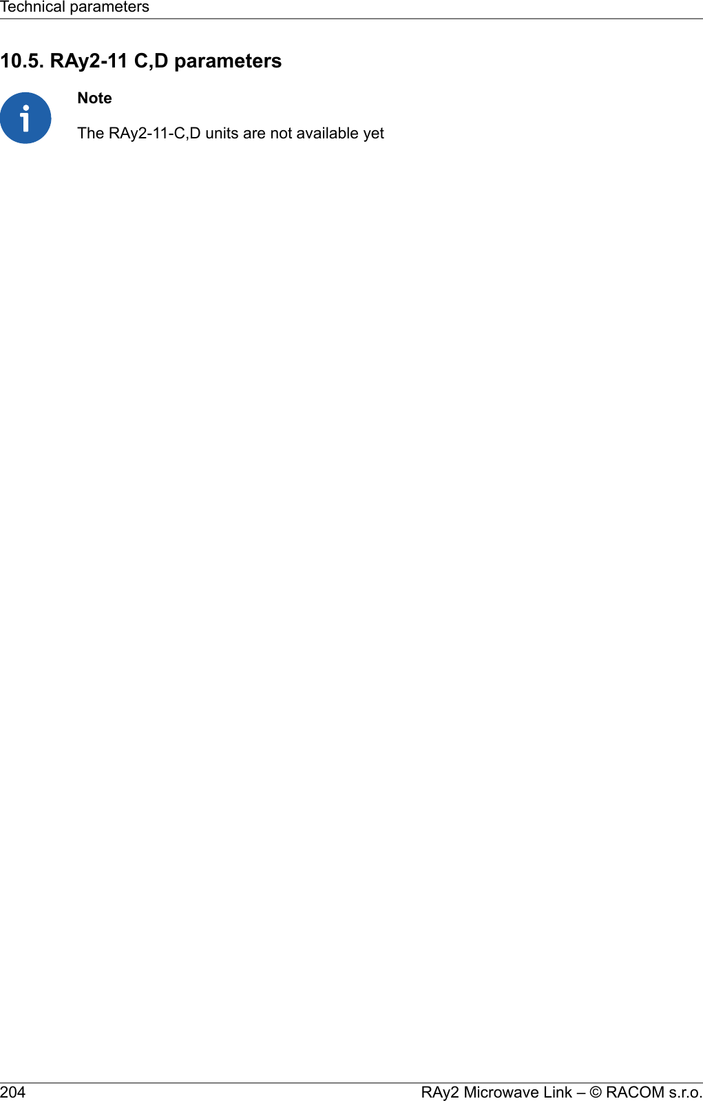
![10.6. RAy2-17 parameters10.6.1. Upper/Lower LimitsTX powerRAy2-17MaxMinModulation [dBm][dBm]5-25QPSK5-2516-QAM5-2532-QAM5-2564-QAM5-25128-QAM5-25256-QAMver. 2.0Minimum (hw limit) and default duplex spacing.Optional duplex spacingRAy2-17defaultminChannel width[MHz][MHz][MHz]73.5603.573.560787.5651484702870704087.58450848456ver. 2.6Band RangeRAy2-17Unit UUnit L[MHz][MHz]17.10017.100min17.30017.300maxver. 1.0205© RACOM s.r.o. – RAy2 Microwave LinkTechnical parameters](https://usermanual.wiki/Racom/RAY2-24/User-Guide-2944903-Page-205.png)
![10.6.2. Radio parametersChannel spacing 3.5 MHz; ACCP operationRAy2-17Adjacent channel SelectivityCo-channel rejectionRSS / SNR forBER 10-6UserBitRateRawBitRateModula-tion3 dB1 dB3 dB1 dBdeclared / limitdeclared / limitdeclared / limitdeclared / limitSNRRSS[dB][dB][dB][dB][dB][dBm][Mbps][-]-4/-160/-1419/1223/159.5-974.96QPSK-7/-15-3/-1326.5/2030/2215.0-909.61216-QAM-7/-14-3/-1226.5/2230/2418.5-8712.11532-QAM-7/-12-3/-1126.5/2630/2920.5-8414.31864-QAM-7/-8-3/-926.5/2830/3023.5-8317.221128-QAM-7/-7-3/-526.5/3130/3326.0-8119.724256-QAMver. 2.1Channel spacing 7 MHz; ACCP operationRAy2-17Adjacent channel SelectivityCo-channel rejectionRSS / SNR forBER 10-6UserBitRateRawBitRateModula-tion3 dB1 dB3 dB1 dBdeclared / limitdeclared / limitdeclared / limitdeclared / limitSNRRSS[dB][dB][dB][dB][dB][dBm][Mbps][-]-4/-220/-2019/1223/158.5-958.512QPSK-7/-19-3/-1826.5/2030/2215.0-8817.22416-QAM-6/-18-2/-1633/2237/2418.5-8522.13032-QAM-6/-16-2/-1433/2637/2921.5-8129.73664-QAM-6/-14-2/-1233/3037/3225.0-7934.742128-QAM-6/-12-2/-1033/3137/3326.0-7739.749256-QAMver. 2.1RAy2 Microwave Link – © RACOM s.r.o.206Technical parameters](https://usermanual.wiki/Racom/RAY2-24/User-Guide-2944903-Page-206.png)
![Channel spacing 14 MHz; ACCP operationRAy2-17Adjacent channel SelectivityCo-channel rejectionRSS / SNR forBER 10-6UserBitRateRawBitRateModula-tion3 dB1 dB3 dB1 dBdeclared / limitdeclared / limitdeclared / limitdeclared / limitSNRRSS[dB][dB][dB][dB][dB][dBm][Mbps][-]-4/-230/-2119/1223/148.5-9219.924QPSK-7/-21-3/-1926.5/1830/2015.0-8538.84816-QAM-9/-19-5/-1729/2333/2618.5-8149.16032-QAM-6/-17-2/-1433/2637/2821.5-7862.37264-QAM-6/-14-2/-1233/2837/3025.0-7573.684128-QAM-6/-12-2/-1033/3137/3328.0-7381.296256-QAMver. 2.1Channel spacing 28 MHz; ACCP operationRAy2-17Adjacent channel SelectivityCo-channel rejectionRSS / SNR forBER 10-6UserBitRateRawBitRateModula-tion3 dB1 dB3 dB1 dBdeclared / limitdeclared / limitdeclared / limitdeclared / limitSNRRSS[dB][dB][dB][dB][dB][dBm][Mbps][-]-4/-230/-2119/1023/127.5-9036.850QPSK-7/-20-3/-1826.5/1830/2015.0-8380.910016-QAM-9/-19-5/-1629/2233/2418.5-79102.412532-QAM-8/-15-5/-1232/2635/2821.5-76129.815064-QAM-8/-12-5/-932/2835/3025.0-72155.5175128QAM-8/-9-5/-632/3135/3326.5-69170.7200256-QAMver. 2.0Channel spacing 40 MHz; ACCP operationRAy2-17Adjacent channel SelectivityCo-channel rejectionRSS / SNR forBER 10-6UserBitRateRawBitRateModula-tion3 dB1 dB3 dB1 dBdeclared / limitdeclared / limitdeclared / limitdeclared / limitSNRRSS[dB][dB][dB][dB][dB][dBm][Mbps][-]-8/-24-4/-2229/1033/127.5-8850.168QPSK-8/-21-4/-1829/1733/1915.0-81110.013616-QAM-8/-19-4/-1629/2133/2418.5-77139.217032-QAM-8/-16-4/-1429/2533/2721.5-74176.520464-QAM-8/-12-4/-1033/2837/3025.0-70211.4238128QAM-8/-10-4/-833/3037/3326.5-68232.1272256-QAMver. 2.0207© RACOM s.r.o. – RAy2 Microwave LinkTechnical parameters](https://usermanual.wiki/Racom/RAY2-24/User-Guide-2944903-Page-207.png)
![Channel spacing 50 MHz; ACCP operationRAy2-17Adjacent channel SelectivityCo-channel rejectionRSS / SNR forBER 10-6UserBitRateRawBitRateModula-tion3 dB1 dB3 dB1 dBdeclared / limitdeclared / limitdeclared / limitdeclared / limitSNRRSS[dB][dB][dB][dB][dB][dBm][Mbps][-]-4/-260/-2419/1023/127.5-87.566.390QPSK-7/-21-3/-1826.5/1730/1915.0-80.5145.618016-QAM-9/-19-5/-1629/2233/2418.5-76.5184.222532-QAM-8/-16-5/-1432/2535/2721.5-73.5233.627064-QAM-8/-12-5/-1032/2835/3025.0-69.5276.1315128QAM-8/-10-5/-832/3035/3326.5-66.5320.6360256-QAMver. 1.0Channel spacing 56 MHz; ACCP operationRAy2-17Adjacent channel SelectivityCo-channel rejectionRSS / SNR forBER 10-6UserBitRateRawBitRateModula-tion3 dB1 dB3 dB1 dBdeclared / limitdeclared / limitdeclared / limitdeclared / limitSNRRSS[dB][dB][dB][dB][dB][dBm][Mbps][-]-4/-260/-2419/1023/127.5-8772.999QPSK-7/-21-3/-1826.5/1730/1915.0-80160.219816-QAM-9/-19-5/-1629/2233/2418.5-76202.7247.532-QAM-8/-16-5/-1432/2535/2721.5-73256.929764-QAM-8/-12-5/-1032/2835/3025.0-69303.7346.5128QAM-8/-10-5/-832/3035/3326.5-66337.7396256-QAMver. 2.0Channel spacing 56 MHz TO; ACCP operationRAy2-17Adjacent channel SelectivityCo-channel rejectionRSS / SNR forBER 10-6UserBitRateRawBitRateModula-tion3 dB1 dB3 dB1 dBdeclared / limitdeclared / limitdeclared / limitdeclared / limitSNRRSS[dB][dB][dB][dB][dB][dBm][Mbps][-]-4/-260/-2419/1123/1310.0-8585.899QPSK-7/-20-3/-1826.5/1830/2016.0-78169.919816-QAM-9/-15-5/-1429/2333/2519.0-74206.2247.532-QAM-8/-11-5/-932/2635/2922.5-70268.129764-QAM-8/-10-5/-832/2935/3225.5-67309.0346.5128-QAM-8/-8-5/-732/3235/3527.5-64358.9396256-QAMver. 2.1RAy2 Microwave Link – © RACOM s.r.o.208Technical parameters](https://usermanual.wiki/Racom/RAY2-24/User-Guide-2944903-Page-208.png)
![10.6.3. Nominal frequencies RAy2-17 TX channel nominal frequenciesduplex spacing range 63 – 189 MHz(Freq.table: rcinfo17_default:14)basic channels (default duplex) optional channelsCh.No. Lower [MHz] Ch.No. Upper [MHz] Ch.No. Lower [MHz] Ch.No. Upper [MHz]###U19 17168.0###no more channelsU20 17171.5###U21 17175.0###L1 17105.0 U22 17178.5###L2 17108.5 U23 17182.0###L3 17112.0 U24 17185.5###L4 17115.5 U25 17189.0###L5 17119.0 U26 17192.5###L6 17122.5 U27 17196.0###L7 17126.0 U28 17199.5###L8 17129.5 U29 17203.0###L9 17133.0 U30 17206.5###L10 17136.5 U31 17210.0###L11 17140.0 U32 17213.5###L12 17143.5 U33 17217.0###L13 17147.0 U34 17220.5###L14 17150.5 U35 17224.0###L15 17154.0 U36 17227.5###L16 17157.5 U37 17231.0###L17 17161.0 U38 17234.5###L18 17164.5 U39 17238.0###L19 17168.0 U40 17241.5###L20 17171.5 U41 17245.0###L21 17175.0 U42 17248.5###L22 17178.5 U43 17252.0###L23 17182.0 U44 17255.5###L24 17185.5 U45 17259.0###L25 17189.0 U46 17262.5###L26 17192.5 U47 17266.0###L27 17196.0 U48 17269.5###L28 17199.5 U49 17273.0###L29 17203.0 U50 17276.5###L30 17206.5 U51 17280.0###L31 17210.0 U52 17283.5###L32 17213.5 U53 17287.0###L33 17217.0 U54 17290.5###L34 17220.5 U55 17294.0###L35 17224.0###L36 17227.5###L37 17231.0ver. 2.1 Band 17.1 – 17.3 GHz, default duplex sp. 73.5 MHzBandwidth: 3.5 MHz209© RACOM s.r.o. – RAy2 Microwave LinkTechnical parameters](https://usermanual.wiki/Racom/RAY2-24/User-Guide-2944903-Page-209.png)
![RAy2-17 TX channel nominal frequenciesduplex spacing range 63 – 189 MHz(Freq.table: rcinfo17_default:14)basic channels (default duplex) optional channelsCh.No. Lower [MHz] Ch.No. Upper [MHz] Ch.No. Lower [MHz] Ch.No. Upper [MHz]U19 17168.0U20 17171.5U21 17175.0L1 17105.0 U22 17178.5L2 17108.5 U23 17182.0L3 17112.0 U24 17185.5L4 17115.5 U25 17189.0L5 17119.0 U26 17192.5L6 17122.5 U27 17196.0L7 17126.0 U28 17199.5L8 17129.5 U29 17203.0L9 17133.0 U30 17206.5L10 17136.5 U31 17210.0L11 17140.0 U32 17213.5L12 17143.5 U33 17217.0L13 17147.0 U34 17220.5L14 17150.5 U35 17224.0L15 17154.0 U36 17227.5L16 17157.5 U37 17231.0L17 17161.0 U38 17234.5L18 17164.5 U39 17238.0L19 17168.0 U40 17241.5L20 17171.5 U41 17245.0L21 17175.0 U42 17248.5L22 17178.5 U43 17252.0L23 17182.0 U44 17255.5L24 17185.5 U45 17259.0L25 17189.0 U46 17262.5L26 17192.5 U47 17266.0L27 17196.0 U48 17269.5L28 17199.5 U49 17273.0L29 17203.0 U50 17276.5L30 17206.5 U51 17280.0L31 17210.0 U52 17283.5L32 17213.5 U53 17287.0L33 17217.0 U54 17290.5L34 17220.5 U55 17294.0L35 17224.0L36 17227.5L37 17231.0ver. 2.1 Band 17.1 – 17.3 GHz, default duplex sp. 73.5 MHzBandwidth: 7 MHzRAy2 Microwave Link – © RACOM s.r.o.210Technical parameters](https://usermanual.wiki/Racom/RAY2-24/User-Guide-2944903-Page-210.png)
![RAy2-17 TX channel nominal frequenciesduplex spacing range 66.5 – 182 MHz(Freq.table: rcinfo17_default:14)basic channels (default duplex) optional channelsCh.No. Lower [MHz] Ch.No. Upper [MHz] Ch.No. Lower [MHz] Ch.No. Upper [MHz]############U21 17175.0###U22 17178.5#########U23 17182.0######U24 17185.5######U25 17189.0U26 17192.5######L2 17108.5 U27 17196.0###L3 17112.0 U28 17199.5###L4 17115.5 U29 17203.0L5 17119.0 U30 17206.5######L6 17122.5 U31 17210.0###L7 17126.0 U32 17213.5###L8 17129.5 U33 17217.0L9 17133.0 U34 17220.5######L10 17136.5 U35 17224.0###L11 17140.0 U36 17227.5###L12 17143.5 U37 17231.0L13 17147.0 U38 17234.5######L14 17150.5 U39 17238.0###L15 17154.0 U40 17241.5###L16 17157.5 U41 17245.0L17 17161.0 U42 17248.5######L18 17164.5 U43 17252.0###L19 17168.0 U44 17255.5###L20 17171.5 U45 17259.0L21 17175.0 U46 17262.5######L22 17178.5 U47 17266.0###L23 17182.0 U48 17269.5###L24 17185.5 U49 17273.0L25 17189.0 U50 17276.5######L26 17192.5 U51 17280.0###L27 17196.0 U52 17283.5###L28 17199.5 U53 17287.0L29 17203.0 U54 17290.5######L30 17206.5###L31 17210.0###L32 17213.5L33 17217.0######L34 17220.5###L35 17224.0###ver. 2.1Band 17.1 – 17.3 GHz, default duplex sp. 87.5 MHzBandwidth: 14 MHz211© RACOM s.r.o. – RAy2 Microwave LinkTechnical parameters](https://usermanual.wiki/Racom/RAY2-24/User-Guide-2944903-Page-211.png)
![RAy2-17 TX channel nominal frequenciesduplex spacing range 70 – 168 MHz(Freq.table: rcinfo17_default:14)basic channels (default duplex) optional channelsCh.No. Lower [MHz] Ch.No. Upper [MHz] Ch.No. Lower [MHz] Ch.No. Upper [MHz]U24 17185.5U25 17189.0U26 17192.5U27 17196.0L4 17115.5 U28 17199.5L5 17119.0 U29 17203.0L6 17122.5 U30 17206.5L7 17126.0 U31 17210.0L8 17129.5 U32 17213.5L9 17133.0 U33 17217.0L10 17136.5 U34 17220.5L11 17140.0 U35 17224.0L12 17143.5 U36 17227.5L13 17147.0 U37 17231.0L14 17150.5 U38 17234.5L15 17154.0 U39 17238.0L16 17157.5 U40 17241.5L17 17161.0 U41 17245.0L18 17164.5 U42 17248.5L19 17168.0 U43 17252.0L20 17171.5 U44 17255.5L21 17175.0 U45 17259.0L22 17178.5 U46 17262.5L23 17182.0 U47 17266.0L24 17185.5 U48 17269.5L25 17189.0 U49 17273.0L26 17192.5 U50 17276.5L27 17196.0 U51 17280.0L28 17199.5 U52 17283.5L29 17203.0L30 17206.5L31 17210.0L32 17213.5ver. 2.1 Band 17.1 – 17.3 GHz, default duplex sp. 84 MHzBandwidth: 28 MHzRAy2 Microwave Link – © RACOM s.r.o.212Technical parameters](https://usermanual.wiki/Racom/RAY2-24/User-Guide-2944903-Page-212.png)
![RAy2-17 TX channel nominal frequenciesduplex spacing range 70 – 154 MHz(Freq.table: rcinfo17_default:14)basic channels (default duplex) optional channelsCh.No. Lower [MHz] Ch.No. Upper [MHz] Ch.No. Lower [MHz] Ch.No. Upper [MHz]L6 17122.5 U26 17192.5L7 17126.0 U27 17196.0L8 17129.5 U28 17199.5L9 17133.0 U29 17203.0L10 17136.5 U30 17206.5L11 17140.0 U31 17210.0L12 17143.5 U32 17213.5L13 17147.0 U33 17217.0L14 17150.5 U34 17220.5L15 17154.0 U35 17224.0L16 17157.5 U36 17227.5L17 17161.0 U37 17231.0L18 17164.5 U38 17234.5L19 17168.0 U39 17238.0L20 17171.5 U40 17241.5L21 17175.0 U41 17245.0L22 17178.5 U42 17248.5L23 17182.0 U43 17252.0L24 17185.5 U44 17255.5L25 17189.0 U45 17259.0L26 17192.5 U46 17262.5L27 17196.0 U47 17266.0L28 17199.5 U48 17269.5L29 17203.0 U49 17273.0L30 17206.5 U50 17276.5ver. 2.1 Band 17.1 – 17.3 GHz, default duplex sp. 70 MHzBandwidth: 40 MHz213© RACOM s.r.o. – RAy2 Microwave LinkTechnical parameters](https://usermanual.wiki/Racom/RAY2-24/User-Guide-2944903-Page-213.png)
![RAy2-17 TX channel nominal frequenciesBand 17.1 – 17.3 GHz, duplex spacing 87.5 MHz Bandwidth: 50 MHz duplex spacing range 84 – 143.5 MHz(Freq.table: rcinfo17_default:17)basic channels (default duplex) optional channelsCh.No. Lower [MHz] Ch.No. Upper [MHz] Ch.No. Lower [MHz] Ch.No. Upper [MHz]U32 17213.5L8 17129.5 U33 17217.0L9 17133.0 U34 17220.5L10 17136.5 U35 17224.0L11 17140.0 U36 17227.5L12 17143.5 U37 17231.0L13 17147.0 U38 17234.5L14 17150.5 U39 17238.0L15 17154.0 U40 17241.5L16 17157.5 U41 17245.0L17 17161.0 U42 17248.5L18 17164.5 U43 17252.0L19 17168.0 U44 17255.5L20 17171.5 U45 17259.0L21 17175.0 U46 17262.5L22 17178.5 U47 17266.0L23 17182.0 U48 17269.5L24 17185.5 U49 17273.0L25 17189.0ver. 1.0 RAy2 Microwave Link – © RACOM s.r.o.214Technical parameters](https://usermanual.wiki/Racom/RAY2-24/User-Guide-2944903-Page-214.png)
![RAy2-17 TX channel nominal frequenciesduplex spacing range 84 – 140 MHz(Freq.table: rcinfo17_default:14)basic channels (default duplex) optional channelsCh.No. Lower [MHz] Ch.No. Upper [MHz] Ch.No. Lower [MHz] Ch.No. Upper [MHz]######L8 17129.5 U32 17213.5L9 17133.0 U33 17217.0L10 17136.5 U34 17220.5L11 17140.0 U35 17224.0L12 17143.5 U36 17227.5L13 17147.0 U37 17231.0L14 17150.5 U38 17234.5L15 17154.0 U39 17238.0L16 17157.5 U40 17241.5L17 17161.0 U41 17245.0L18 17164.5 U42 17248.5L19 17168.0 U43 17252.0L20 17171.5 U44 17255.5L21 17175.0 U45 17259.0L22 17178.5 U46 17262.5L23 17182.0 U47 17266.0L24 17185.5 U48 17269.5ver. 2.1 Band 17.1 – 17.3 GHz, default duplex sp. 84 MHzBandwidth: 56 MHz215© RACOM s.r.o. – RAy2 Microwave LinkTechnical parameters](https://usermanual.wiki/Racom/RAY2-24/User-Guide-2944903-Page-215.png)
![10.7. RAy2-18 parameters10.7.1. Upper/Lower LimitsTX powerRAy2-18-xA,RAy2-18-xBMaxMinModulation [dBm][dBm]24-10QPSK23-1016-QAM22-1032-QAM21-1064-QAM20-10128-QAM19-10256-QAMver. 1.0Duplex spacingRAy2-18-xA,RAy2-18-xB[MHz]Sub-band1008, 1010A1008, 1010Bver. 1.0Sub-band RangeRAy2-18-xA,RAy2-18-xBUnit UUnit LSub-band[MHz][MHz]18.71017.700minA19.21918.209max19.17718.167minB19.70018.690maxver. 1.0RAy2 Microwave Link – © RACOM s.r.o.216Technical parameters](https://usermanual.wiki/Racom/RAY2-24/User-Guide-2944903-Page-216.png)
![10.7.2. Radio parametersChannel spacing 1.75 MHz; ACCP operationRAy2-18Adjacent channel SelectivityCo-channel rejectionRSS / SNR forBER 10-6UserBitRateRawBitRateModula-tion3 dB1 dB3 dB1 dBdeclared / limitdeclared / limitdeclared / limitdeclared / limitSNRRSS[dB][dB][dB][dB][dB][dBm][Mbps][-]-4/-140/-1219/1223/159.5-972.543.13QPSK-5/-13-1/-1126.5/2030/2215.0-914.956.2616-QAM-5/-12-1/-1026.5/2230/2419.0-886.267.8332-QAM-5/-10-1/-926.5/2630/2920.5-857.379.3964-QAM-5/-7-1/-826.5/2830/3023.5-82.58.8910.96128-QAMver. 1.0Channel spacing 2.5 MHz; ACCP operationRAy2-18Adjacent channel SelectivityCo-channel rejectionRSS / SNR forBER 10-6UserBitRateRawBitRateModula-tion3 dB1 dB3 dB1 dBdeclared / limitdeclared / limitdeclared / limitdeclared / limitSNRRSS[dB][dB][dB][dB][dB][dBm][Mbps][-]-4/-160/-1419/1223/158.5-96.03.244QPSK-5/-15-1/-1326.5/2030/2215.0-90.56.33816-QAM-8/-14-4/-1226.5/2230/2418.5-87.58.011032-QAM-8/-12-4/-1126.5/2630/2921.5-84.59.421264-QAM-4/-80/-933/2837/3025.0-81.511.3614128-QAM-4/-70/-533/3137/3326.0-78.513.0116256-QAMver 1.0217© RACOM s.r.o. – RAy2 Microwave LinkTechnical parameters](https://usermanual.wiki/Racom/RAY2-24/User-Guide-2944903-Page-217.png)
![Channel spacing 3.5 MHz; ACCP operationRAy2-18Adjacent channel SelectivityCo-channel rejectionRSS / SNR forBER 10-6UserBitRateRawBitRateModula-tion3 dB1 dB3 dB1 dBdeclared / limitdeclared / limitdeclared / limitdeclared / limitSNRRSS[dB][dB][dB][dB][dB][dBm][Mbps][-]-4/-160/-1419/1223/159.5-944.96QPSK-5/-15-1/-1326.5/2030/2215.0-899.61216-QAM-8/-14-4/-1226.5/2230/2418.5-8612.11532-QAM-8/-12-4/-1126.5/2630/2920.5-8314.31864-QAM-4/-80/-933/2837/3023.5-8017.221128-QAM-4/-70/-533/3137/3326.0-7719.724256-QAMver. 1.0Channel spacing 3.75 MHz; ACCP operationRAy2-18Adjacent channel SelectivityCo-channel rejectionRSS / SNR forBER 10-6UserBitRateRawBitRateModula-tion3 dB1 dB3 dB1 dBdeclared / limitdeclared / limitdeclared / limitdeclared / limitSNRRSS[dB][dB][dB][dB][dB][dBm][Mbps][-]-4/-160/-1419/1223/159.5-944.96QPSK-5/-15-1/-1326.5/2030/2215.0-899.61216-QAM-8/-14-4/-1226.5/2230/2418.5-8612.11532-QAM-8/-12-4/-1126.5/2630/2920.5-8314.31864-QAM-4/-80/-933/2837/3023.5-8017.221128-QAM-4/-70/-533/3137/3326.0-7719.724256-QAMver. 1.0Channel spacing 5 MHz; ACCP operationRAy2-18Adjacent channel SelectivityCo-channel rejectionRSS / SNR forBER 10-6UserBitRateRawBitRateModula-tion3 dB1 dB3 dB1 dBdeclared / limitdeclared / limitdeclared / limitdeclared / limitSNRRSS[dB][dB][dB][dB][dB][dBm][Mbps][-]-4/-160/-1419/1223/158.5-94.55.78QPSK-5/-15-1/-1326.5/2030/2215.0-87.511.51616-QAM-8/-14-4/-1226.5/2230/2418.5-84.514.82032-QAM-8/-12-4/-1126.5/2630/2921.5-81.519.82464-QAM-4/-80/-933/2837/3025.0-78.523.128128-QAM-4/-70/-533/3137/3326.0-75.527.232256-QAMver 1.0RAy2 Microwave Link – © RACOM s.r.o.218Technical parameters](https://usermanual.wiki/Racom/RAY2-24/User-Guide-2944903-Page-218.png)
![Channel spacing 7 MHz; ACCP operationRAy2-18Adjacent channel SelectivityCo-channel rejectionRSS / SNR forBER 10-6UserBitRateRawBitRateModula-tion3 dB1 dB3 dB1 dBdeclared / limitdeclared / limitdeclared / limitdeclared / limitSNRRSS[dB][dB][dB][dB][dB][dBm][Mbps][-]-4/-220/-2019/1223/158.5-928.512QPSK-5/-19-1/-1826.5/2030/2215.0-8517.22416-QAM-5/-18-1/-1626.5/2230/2418.5-8222.13032-QAM-7/-16-3/-1430/2634/2921.5-7929.73664-QAM-7.5/-14-3.5/-1233/3037/3225.0-7634.742128-QAM-4/-120/-1036/3140/3326.0-7339.749256-QAMver. 1.0Channel spacing 7.5 MHz; ACCP operationRAy2-18Adjacent channel SelectivityCo-channel rejectionRSS / SNR forBER 10-6UserBitRateRawBitRateModula-tion3 dB1 dB3 dB1 dBdeclared / limitdeclared / limitdeclared / limitdeclared / limitSNRRSS[dB][dB][dB][dB][dB][dBm][Mbps][-]-4/-220/-2019/1223/158.5-92.59.112.9QPSK-7/-19-3/-1826.5/2030/2215.0-84.518.425.716-QAM-7/-18-3/-1626.5/2230/2418.5-81.523.732.232-QAM-7/-16-3/-1430/2634/2921.5-78.531.838.664-QAM-6/-14-2/-1233/3037/3225.0-75.537.145.0128-QAM-4/-120/-1036/3140/3326.0-72.542.551.4256-QAMver. 1.0Channel spacing 13.75 MHz; ACCP operationRAy2-18Adjacent channel SelectivityCo-channel rejectionRSS / SNR forBER 10-6UserBitRateRawBitRateModula-tion3 dB1 dB3 dB1 dBdeclared / limitdeclared / limitdeclared / limitdeclared / limitSNRRSS[dB][dB][dB][dB][dB][dBm][Mbps][-]-3/-231/-2119/1223/148.5-8919.924QPSK-4/-210/-1926.5/1830/2015.0-8338.84816-QAM-5.5/-19-2/-1726.5/2330/2618.5-8049.16032-QAM-7/-17-3/-1430/2634/2821.5-7762.37264-QAM-7.5/-14-3.5/-1233/2837/3025.0-7473.684128-QAM-4/-120/-1036/3140/3328.0-7181.296256-QAMver. 1.0219© RACOM s.r.o. – RAy2 Microwave LinkTechnical parameters](https://usermanual.wiki/Racom/RAY2-24/User-Guide-2944903-Page-219.png)
![Channel spacing 27.5 MHz; ACCP operationRAy2-18Adjacent channel SelectivityCo-channel rejectionRSS / SNR forBER 10-6UserBitRateRawBitRateModula-tion3 dB1 dB3 dB1 dBdeclared / limitdeclared / limitdeclared / limitdeclared / limitSNRRSS[dB][dB][dB][dB][dB][dBm][Mbps][-]-3/-231/-2119/1023/127.5-8736.850QPSK-4/-200/-1826.5/1830/2015.0-7980.910016-QAM-5.5/-19-2/-1626.5/2230/2418.5-76102.412532-QAM-7/-15-3/-1230/2634/2821.5-73129.815064-QAM-7/-12-3/-933/2837/3025.0-70155.5175128-QAM-4/-90/-636/3140/3326.5-67170.7200256-QAMver. 1.0Channel spacing 55 MHz; ACCP operationRAy2-18Adjacent channel SelectivityCo-channel rejectionRSS / SNR forBER 10-6UserBitRateRawBitRateModula-tion3 dB1 dB3 dB1 dBdeclared / limitdeclared / limitdeclared / limitdeclared / limitSNRRSS[dB][dB][dB][dB][dB][dBm][Mbps][-]-3/-261/-2419/1023/127.5-8472.999QPSK-9/-21-5/-1825/1729/1915.0-75160.219816-QAM-5.5/-19-2/-1626.5/2230/2418.5-72.5202.7247.532-QAM-7/-16-3/-1430/2534/2721.5-70256.929764-QAM-7.5/-12-3.5/-1033/2837/3025.0-67303.7346.5128-QAM-4/-100/-836/3040/3326.5-64337.7396256-QAMver. 1.0Channel spacing 55 MHz TO; ACCP operationRAy2-18Adjacent channel SelectivityCo-channel rejectionRSS / SNR forBER 10-6UserBitRateRawBitRateModula-tion3 dB1 dB3 dB1 dBdeclared / limitdeclared / limitdeclared / limitdeclared / limitSNRRSS[dB][dB][dB][dB][dB][dBm][Mbps][-]-3/-261/-2419/1123/1310.0-8485.899QPSK-9/-20-5/-1825/1829/2016.0-77169.919816-QAM-5.5/-15-2/-1426.5/2330/2519.0-73206.2247.532-QAM-7/-11-3/-930/2634/2922.5-69268.129764-QAM-7.5/-10-3.5/-833/2937/3225.5-66309.0346.5128-QAM-4/-80/-736/3240/3527.5-63358.9396256-QAMver. 1.0RAy2 Microwave Link – © RACOM s.r.o.220Technical parameters](https://usermanual.wiki/Racom/RAY2-24/User-Guide-2944903-Page-220.png)
![10.7.3. Nominal frequenciesTX channel nominal frequenciesBand 17.7 – 19.7 GHz, duplex spacing 1010 MHzBandwidth: 1.75 MHz ITU-R F.595-9 (-10), Annex 5.c( Freq.table: rcinfo18_A_default:5 )Ch.No. Lower [MHz] Upper [MHz] Ch.No. Lower [MHz] Upper [MHz] Ch.No. Lower [MHz] Upper [MHz] Ch.No. Lower [MHz] Upper [MHz]1 17703.875 18713.875 74 17831.625 18841.625 147 17959.375 18969.375 220 18087.125 19097.1252 17705.625 18715.625 75 17833.375 18843.375 148 17961.125 18971.125 221 18088.875 19098.8753 17707.375 18717.375 76 17835.125 18845.125 149 17962.875 18972.875 222 18090.625 19100.6254 17709.125 18719.125 77 17836.875 18846.875 150 17964.625 18974.625 223 18092.375 19102.3755 17710.875 18720.875 78 17838.625 18848.625 151 17966.375 18976.375 224 18094.125 19104.1256 17712.625 18722.625 79 17840.375 18850.375 152 17968.125 18978.125 225 18095.875 19105.8757 17714.375 18724.375 80 17842.125 18852.125 153 17969.875 18979.875 226 18097.625 19107.6258 17716.125 18726.125 81 17843.875 18853.875 154 17971.625 18981.625 227 18099.375 19109.3759 17717.875 18727.875 82 17845.625 18855.625 155 17973.375 18983.375 228 18101.125 19111.12510 17719.625 18729.625 83 17847.375 18857.375 156 17975.125 18985.125 229 18102.875 19112.87511 17721.375 18731.375 84 17849.125 18859.125 157 17976.875 18986.875 230 18104.625 19114.62512 17723.125 18733.125 85 17850.875 18860.875 158 17978.625 18988.625 231 18106.375 19116.37513 17724.875 18734.875 86 17852.625 18862.625 159 17980.375 18990.375 232 18108.125 19118.12514 17726.625 18736.625 87 17854.375 18864.375 160 17982.125 18992.125 233 18109.875 19119.87515 17728.375 18738.375 88 17856.125 18866.125 161 17983.875 18993.875 234 18111.625 19121.62516 17730.125 18740.125 89 17857.875 18867.875 162 17985.625 18995.625 235 18113.375 19123.37517 17731.875 18741.875 90 17859.625 18869.625 163 17987.375 18997.375 236 18115.125 19125.12518 17733.625 18743.625 91 17861.375 18871.375 164 17989.125 18999.125 237 18116.875 19126.87519 17735.375 18745.375 92 17863.125 18873.125 165 17990.875 19000.875 238 18118.625 19128.62520 17737.125 18747.125 93 17864.875 18874.875 166 17992.625 19002.625 239 18120.375 19130.37521 17738.875 18748.875 94 17866.625 18876.625 167 17994.375 19004.375 240 18122.125 19132.12522 17740.625 18750.625 95 17868.375 18878.375 168 17996.125 19006.125 241 18123.875 19133.87523 17742.375 18752.375 96 17870.125 18880.125 169 17997.875 19007.875 242 18125.625 19135.62524 17744.125 18754.125 97 17871.875 18881.875 170 17999.625 19009.625 243 18127.375 19137.37525 17745.875 18755.875 98 17873.625 18883.625 171 18001.375 19011.375 244 18129.125 19139.12526 17747.625 18757.625 99 17875.375 18885.375 172 18003.125 19013.125 245 18130.875 19140.87527 17749.375 18759.375 100 17877.125 18887.125 173 18004.875 19014.875 246 18132.625 19142.62528 17751.125 18761.125 101 17878.875 18888.875 174 18006.625 19016.625 247 18134.375 19144.37529 17752.875 18762.875 102 17880.625 18890.625 175 18008.375 19018.375 248 18136.125 19146.12530 17754.625 18764.625 103 17882.375 18892.375 176 18010.125 19020.125 249 18137.875 19147.87531 17756.375 18766.375 104 17884.125 18894.125 177 18011.875 19021.875 250 18139.625 19149.62532 17758.125 18768.125 105 17885.875 18895.875 178 18013.625 19023.625 251 18141.375 19151.37533 17759.875 18769.875 106 17887.625 18897.625 179 18015.375 19025.375 252 18143.125 19153.12534 17761.625 18771.625 107 17889.375 18899.375 180 18017.125 19027.125 253 18144.875 19154.87535 17763.375 18773.375 108 17891.125 18901.125 181 18018.875 19028.875 254 18146.625 19156.62536 17765.125 18775.125 109 17892.875 18902.875 182 18020.625 19030.625 255 18148.375 19158.37537 17766.875 18776.875 110 17894.625 18904.625 183 18022.375 19032.375 256 18150.125 19160.12538 17768.625 18778.625 111 17896.375 18906.375 184 18024.125 19034.125 257 18151.875 19161.87539 17770.375 18780.375 112 17898.125 18908.125 185 18025.875 19035.875 258 18153.625 19163.62540 17772.125 18782.125 113 17899.875 18909.875 186 18027.625 19037.625 259 18155.375 19165.37541 17773.875 18783.875 114 17901.625 18911.625 187 18029.375 19039.375 260 18157.125 19167.12542 17775.625 18785.625 115 17903.375 18913.375 188 18031.125 19041.125 261 18158.875 19168.87543 17777.375 18787.375 116 17905.125 18915.125 189 18032.875 19042.875 262 18160.625 19170.62544 17779.125 18789.125 117 17906.875 18916.875 190 18034.625 19044.625 263 18162.375 19172.37545 17780.875 18790.875 118 17908.625 18918.625 191 18036.375 19046.375 264 18164.125 19174.12546 17782.625 18792.625 119 17910.375 18920.375 192 18038.125 19048.125 265 18165.875 19175.87547 17784.375 18794.375 120 17912.125 18922.125 193 18039.875 19049.875 266 18167.625 19177.62548 17786.125 18796.125 121 17913.875 18923.875 194 18041.625 19051.625 267 18169.375 19179.37549 17787.875 18797.875 122 17915.625 18925.625 195 18043.375 19053.375 268 18171.125 19181.12550 17789.625 18799.625 123 17917.375 18927.375 196 18045.125 19055.125 269 18172.875 19182.8755117791.375 18801.375 124 17919.125 18929.125 197 18046.875 19056.875 270 18174.625 19184.6255217793.125 18803.125 125 17920.875 18930.875 198 18048.625 19058.625 271 18176.375 19186.3755317794.875 18804.875 126 17922.625 18932.625 199 18050.375 19060.375 272 18178.125 19188.1255417796.625 18806.625 127 17924.375 18934.375 200 18052.125 19062.125 273 18179.875 19189.8755517798.375 18808.375 128 17926.125 18936.125 201 18053.875 19063.875 274 18181.625 19191.6255617800.125 18810.125 129 17927.875 18937.875 202 18055.625 19065.625 275 18183.375 19193.3755717801.875 18811.875 130 17929.625 18939.625 203 18057.375 19067.375 276 18185.125 19195.12558 17803.625 18813.625 131 17931.375 18941.375 204 18059.125 19069.125 277 18186.875 19196.87559 17805.375 18815.375 132 17933.125 18943.125 205 18060.875 19070.875 278 18188.625 19198.62560 17807.125 18817.125 133 17934.875 18944.875 206 18062.625 19072.625 279 18190.375 19200.37561 17808.875 18818.875 134 17936.625 18946.625 207 18064.375 19074.375 280 18192.125 19202.12562 17810.625 18820.625 135 17938.375 18948.375 208 18066.125 19076.125 281 18193.875 19203.87563 17812.375 18822.375 136 17940.125 18950.125 209 18067.875 19077.875 282 18195.625 19205.62564 17814.125 18824.125 137 17941.875 18951.875 210 18069.625 19079.625 283 18197.375 19207.37565 17815.875 18825.875 138 17943.625 18953.625 211 18071.375 19081.375 284 18199.125 19209.12566 17817.625 18827.625 139 17945.375 18955.375 212 18073.125 19083.125 285 18200.875 19210.87567 17819.375 18829.375 140 17947.125 18957.125 213 18074.875 19084.875 286 18202.625 19212.62568 17821.125 18831.125 141 17948.875 18958.875 214 18076.625 19086.625 287 18204.375 19214.37569 17822.875 18832.875 142 17950.625 18960.625 215 18078.375 19088.375 288 18206.125 19216.12570 17824.625 18834.625 143 17952.375 18962.375 216 18080.125 19090.125 289 18207.875 19217.87571 17826.375 18836.375 144 17954.125 18964.125 217 18081.875 19091.87572 17828.125 18838.125 145 17955.875 18965.875 218 18083.625 19093.62573 17829.875 18839.875 146 17957.625 18967.625 219 18085.375 19095.37574 17831.6 18841.6 Ver. 1.0 RAy2-18 - xA, RAy2-18 - xB A sub-band 221© RACOM s.r.o. – RAy2 Microwave LinkTechnical parameters](https://usermanual.wiki/Racom/RAY2-24/User-Guide-2944903-Page-221.png)
![TX channel nominal frequenciesBand 17.7 – 19.7 GHz, duplex spacing 1010 MHzBandwidth: 1.75 MHz ITU-R F.595-9 (-10), Annex 5.c( Freq.table: rcinfo18_B_default:5 )Ch.No. Lower [MHz] Upper [MHz] Ch.No. Lower [MHz] Upper [MHz] Ch.No. Lower [MHz] Upper [MHz] Ch.No. Lower [MHz] Upper [MHz]267 18169.375 19179.375 342 18300.625 19310.625 417 18351.375 19361.375 491 18561.375 19571.375268 18171.125 19181.125 343 18302.375 19312.375 418 18353.125 19363.125 492 18563.125 19573.125269 18172.875 19182.875 344 18304.125 19314.125 419 18354.875 19364.875 493 18564.875 19574.875270 18174.625 19184.625 345 18305.875 19315.875 420 18356.625 19366.625 494 18566.625 19576.625271 18176.375 19186.375 346 18307.625 19317.625 421 18358.375 19368.375 495 18568.375 19578.375272 18178.125 19188.125 347 18309.375 19319.375 422 18360.125 19370.125 496 18570.125 19580.125273 18179.875 19189.875 348 18311.125 19321.125 423 18361.875 19371.875 497 18571.875 19581.875274 18181.625 19191.625 349 18312.875 19322.875 424 18363.625 19373.625 498 18573.625 19583.625275 18183.375 19193.375 350 18314.625 19324.625 425 18365.375 19375.375 499 18575.375 19585.375276 18185.125 19195.125 351 18316.375 19326.375 426 18367.125 19377.125 500 18577.125 19587.125277 18186.875 19196.875 352 18318.125 19328.125 427 18368.875 19378.875 501 18578.875 19588.875278 18188.625 19198.625 353 18319.875 19329.875 428 18370.625 19380.625 502 18580.625 19590.625279 18190.375 19200.375 354 18321.625 19331.625 429 18372.375 19382.375 503 18582.375 19592.375280 18192.125 19202.125 355 18323.375 19333.375 430 18374.125 19384.125 504 18584.125 19594.125281 18193.875 19203.875 356 18325.125 19335.125 431 18375.875 19385.875 505 18585.875 19595.875282 18195.625 19205.625 357 18326.875 19336.875 432 18377.625 19387.625 506 18587.625 19597.625283 18197.375 19207.375 358 18328.625 19338.625 433 18379.375 19389.375 507 18589.375 19599.375284 18199.125 19209.125 359 18330.375 19340.375 434 18381.125 19391.125 508 18591.125 19601.125285 18200.875 19210.875 360 18332.125 19342.125 435 18382.875 19392.875 509 18592.875 19602.875286 18202.625 19212.625 361 18333.875 19343.875 436 18384.625 19394.625 510 18594.625 19604.625287 18204.375 19214.375 362 18335.625 19345.625 437 18386.375 19396.375 511 18596.375 19606.375288 18206.125 19216.125 363 18337.375 19347.375 438 18388.125 19398.125 512 18598.125 19608.125289 18207.875 19217.875 364 18339.125 19349.125 439 18389.875 19399.875 513 18599.875 19609.875290 18209.625 19219.625 365 18340.875 19350.875 440 18391.625 19401.625 514 18601.625 19611.625291 18211.375 19221.375 366 18342.625 19352.625 441 18393.375 19403.375 515 18603.375 19613.375292 18213.125 19223.125 367 18344.375 19354.375 442 18395.125 19405.125 516 18605.125 19615.125293 18214.875 19224.875 368 18346.125 19356.125 443 18396.875 19406.875 517 18606.875 19616.875294 18216.625 19226.625 369 18347.875 19357.875 444 18398.625 19408.625 518 18608.625 19618.625295 18218.375 19228.375 370 18349.625 19359.625 445 18400.375 19410.375 519 18610.375 19620.375296 18220.125 19230.125 371 18351.375 19361.375 446 18402.125 19412.125 520 18612.125 19622.125297 18221.875 19231.875 372 18353.125 19363.125 447 18403.875 19413.875 521 18613.875 19623.875298 18223.625 19233.625 373 18354.875 19364.875 448 18405.625 19415.625 522 18615.625 19625.625299 18225.375 19235.375 374 18356.625 19366.625 449 18407.375 19417.375 523 18617.375 19627.375300 18227.125 19237.125 375 18358.375 19368.375 450 18409.125 19419.125 524 18619.125 19629.125301 18228.875 19238.875 376 18360.125 19370.125 451 18410.875 19420.875 525 18620.875 19630.875302 18230.625 19240.625 377 18361.875 19371.875 452 18412.625 19422.625 526 18622.625 19632.625303 18232.375 19242.375 378 18363.625 19373.625 453 18414.375 19424.375 527 18624.375 19634.375304 18234.125 19244.125 379 18365.375 19375.375 454 18416.125 19426.125 528 18626.125 19636.125305 18235.875 19245.875 380 18367.125 19377.125 455 18417.875 19427.875 529 18627.875 19637.875306 18237.625 19247.625 381 18368.875 19378.875 456 18419.625 19429.625 530 18629.625 19639.625307 18239.375 19249.375 382 18370.625 19380.625 457 18421.375 19431.375 531 18631.375 19641.375308 18241.125 19251.125 383 18372.375 19382.375 458 18423.125 19433.125 532 18633.125 19643.125309 18242.875 19252.875 384 18374.125 19384.125 459 18424.875 19434.875 533 18634.875 19644.875310 18244.625 19254.625 385 18375.875 19385.875 460 18426.625 19436.625 534 18636.625 19646.625311 18246.375 19256.375 386 18377.625 19387.625 461 18428.375 19438.375 535 18638.375 19648.375312 18248.125 19258.125 387 18379.375 19389.375 462 18430.125 19440.125 536 18640.125 19650.125313 18249.875 19259.875 388 18381.125 19391.125 463 18431.875 19441.875 537 18641.875 19651.875314 18251.625 19261.625 389 18382.875 19392.875 464 18433.625 19443.625 538 18643.625 19653.625315 18253.375 19263.375 390 18384.625 19394.625 465 18435.375 19445.375 539 18645.375 19655.375316 18255.125 19265.125 391 18386.375 19396.375 466 18437.125 19447.125 540 18647.125 19657.125317 18256.875 19266.875 392 18388.125 19398.125 467 18438.875 19448.875 541 18648.875 19658.875318 18258.625 19268.625 393 18389.875 19399.875 468 18440.625 19450.625 542 18650.625 19660.625319 18260.375 19270.375 394 18391.625 19401.625 469 18442.375 19452.375 543 18652.375 19662.375320 18262.125 19272.125 395 18393.375 19403.375 470 18444.125 19454.125 544 18654.125 19664.125321 18263.875 19273.875 396 18395.125 19405.125 471 18445.875 19455.875 545 18655.875 19665.875322 18265.625 19275.625 397 18396.875 19406.875 472 18447.625 19457.625 546 18657.625 19667.625323 18267.375 19277.375 398 18398.625 19408.625 473 18449.375 19459.375 547 18659.375 19669.375324 18269.125 19279.125 399 18400.375 19410.375 474 18451.125 19461.125 548 18661.125 19671.125325 18270.875 19280.875 400 18402.125 19412.125 475 18452.875 19462.875 549 18662.875 19672.875326 18272.625 19282.625 401 18403.875 19413.875 476 18454.625 19464.625 550 18664.625 19674.625327 18274.375 19284.375 402 18405.625 19415.625 477 18456.375 19466.375 551 18666.375 19676.375328 18276.125 19286.125 403 18407.375 19417.375 478 18458.125 19468.125 552 18668.125 19678.125329 18277.875 19287.875 404 18409.125 19419.125 479 18459.875 19469.875 553 18669.875 19679.875330 18279.625 19289.625 405 18410.875 19420.875 480 18461.625 19471.625 554 18671.625 19681.625331 18281.375 19291.375 406 18412.625 19422.625 481 18463.375 19473.375 555 18673.375 19683.375332 18283.125 19293.125 407 18414.375 19424.375 482 18465.125 19475.125 556 18675.125 19685.125333 18284.875 19294.875 408 18416.125 19426.125 483 18466.875 19476.875 557 18676.875 19686.875334 18286.625 19296.625 409 18417.875 19427.875 484 18468.625 19478.625 558 18678.625 19688.625335 18288.375 19298.375 410 18419.625 19429.625 485 18470.375 19480.375 559 18680.375 19690.375336 18290.125 19300.125 411 18421.375 19431.375 486 18472.125 19482.125 560 18682.125 19692.125337 18291.875 19301.875 412 18423.125 19433.125 487 18473.875 19483.875 561 18683.875 19693.875338 18293.625 19303.625 413 18424.875 19434.875 488 18475.625 19485.625 562 18685.625 19695.625339 18295.375 19305.375 414 18426.625 19436.625 489 18477.375 19487.375 563 18687.375 19697.375340 18297.125 19307.125 415 18428.375 19438.375 490 18479.125 19489.125 564 18689.125 19699.125341 18298.875 19308.875 416 18430.125 19440.125 491 18480.875 19490.875342 18300.625 19310.625 Ver. 1.0 RAy2-18 - xA, RAy2-18 - xB B sub-band RAy2 Microwave Link – © RACOM s.r.o.222Technical parameters](https://usermanual.wiki/Racom/RAY2-24/User-Guide-2944903-Page-222.png)
![TX channel nominal frequenciesBand 17.7 – 19.7 GHz, duplex spacing 1010 MHzBandwidth: 2.5 MHz ITU-R F.595-9, Annex 4 (7.b)( Freq.table: rcinfo18_A_default:5 )Ch.No. Lower [MHz] Upper [MHz] Ch.No. Lower [MHz] Upper [MHz] Ch.No. Lower [MHz] Upper [MHz] Ch.No. Lower [MHz] Upper [MHz]1 17702.5 18712.5 53 17832.5 18842.5 105 17962.5 18972.5 157 18092.5 19102.52 17705.0 18715.0 54 17835.0 18845.0 106 17965.0 18975.0 158 18095.0 19105.03 17707.5 18717.5 55 17837.5 18847.5 107 17967.5 18977.5 159 18097.5 19107.54 17710.0 18720.0 56 17840.0 18850.0 108 17970.0 18980.0 160 18100.0 19110.05 17712.5 18722.5 57 17842.5 18852.5 109 17972.5 18982.5 161 18102.5 19112.56 17715.0 18725.0 58 17845.0 18855.0 110 17975.0 18985.0 162 18105.0 19115.07 17717.5 18727.5 59 17847.5 18857.5 111 17977.5 18987.5 163 18107.5 19117.58 17720.0 18730.0 60 17850.0 18860.0 112 17980.0 18990.0 164 18110.0 19120.09 17722.5 18732.5 61 17852.5 18862.5 113 17982.5 18992.5 165 18112.5 19122.510 17725.0 18735.0 62 17855.0 18865.0 114 17985.0 18995.0 166 18115.0 19125.011 17727.5 18737.5 63 17857.5 18867.5 115 17987.5 18997.5 167 18117.5 19127.512 17730.0 18740.0 64 17860.0 18870.0 116 17990.0 19000.0 168 18120.0 19130.013 17732.5 18742.5 65 17862.5 18872.5 117 17992.5 19002.5 169 18122.5 19132.514 17735.0 18745.0 66 17865.0 18875.0 118 17995.0 19005.0 170 18125.0 19135.015 17737.5 18747.5 67 17867.5 18877.5 119 17997.5 19007.5 171 18127.5 19137.516 17740.0 18750.0 68 17870.0 18880.0 120 18000.0 19010.0 172 18130.0 19140.017 17742.5 18752.5 69 17872.5 18882.5 121 18002.5 19012.5 173 18132.5 19142.518 17745.0 18755.0 70 17875.0 18885.0 122 18005.0 19015.0 174 18135.0 19145.019 17747.5 18757.5 71 17877.5 18887.5 123 18007.5 19017.5 175 18137.5 19147.520 17750.0 18760.0 72 17880.0 18890.0 124 18010.0 19020.0 176 18140.0 19150.021 17752.5 18762.5 73 17882.5 18892.5 125 18012.5 19022.5 177 18142.5 19152.522 17755.0 18765.0 74 17885.0 18895.0 126 18015.0 19025.0 178 18145.0 19155.023 17757.5 18767.5 75 17887.5 18897.5 127 18017.5 19027.5 179 18147.5 19157.524 17760.0 18770.0 76 17890.0 18900.0 128 18020.0 19030.0 180 18150.0 19160.025 17762.5 18772.5 77 17892.5 18902.5 129 18022.5 19032.5 181 18152.5 19162.526 17765.0 18775.0 78 17895.0 18905.0 130 18025.0 19035.0 182 18155.0 19165.027 17767.5 18777.5 79 17897.5 18907.5 131 18027.5 19037.5 183 18157.5 19167.528 17770.0 18780.0 80 17900.0 18910.0 132 18030.0 19040.0 184 18160.0 19170.029 17772.5 18782.5 81 17902.5 18912.5 133 18032.5 19042.5 185 18162.5 19172.530 17775.0 18785.0 82 17905.0 18915.0 134 18035.0 19045.0 186 18165.0 19175.031 17777.5 18787.5 83 17907.5 18917.5 135 18037.5 19047.5 187 18167.5 19177.532 17780.0 18790.0 84 17910.0 18920.0 136 18040.0 19050.0 188 18170.0 19180.033 17782.5 18792.5 85 17912.5 18922.5 137 18042.5 19052.5 189 18172.5 19182.534 17785.0 18795.0 86 17915.0 18925.0 138 18045.0 19055.0 190 18175.0 19185.035 17787.5 18797.5 87 17917.5 18927.5 139 18047.5 19057.5 191 18177.5 19187.536 17790.0 18800.0 88 17920.0 18930.0 140 18050.0 19060.0 192 18180.0 19190.037 17792.5 18802.5 89 17922.5 18932.5 141 18052.5 19062.5 193 18182.5 19192.538 17795.0 18805.0 90 17925.0 18935.0 142 18055.0 19065.0 194 18185.0 19195.039 17797.5 18807.5 91 17927.5 18937.5 143 18057.5 19067.5 195 18187.5 19197.540 17800.0 18810.0 92 17930.0 18940.0 144 18060.0 19070.0 196 18190.0 19200.041 17802.5 18812.5 93 17932.5 18942.5 145 18062.5 19072.5 197 18192.5 19202.542 17805.0 18815.0 94 17935.0 18945.0 146 18065.0 19075.0 198 18195.0 19205.043 17807.5 18817.5 95 17937.5 18947.5 147 18067.5 19077.5 199 18197.5 19207.544 17810.0 18820.0 96 17940.0 18950.0 148 18070.0 19080.0 200 18200.0 19210.045 17812.5 18822.5 97 17942.5 18952.5 149 18072.5 19082.5 201 18202.5 19212.546 17815.0 18825.0 98 17945.0 18955.0 150 18075.0 19085.0 202 18205.0 19215.047 17817.5 18827.5 99 17947.5 18957.5 151 18077.5 19087.5 203 18207.5 19217.548 17820.0 18830.0 100 17950.0 18960.0 152 18080.0 19090.049 17822.5 18832.5 101 17952.5 18962.5 153 18082.5 19092.550 17825.0 18835.0 102 17955.0 18965.0 154 18085.0 19095.051 17827.5 18837.5 103 17957.5 18967.5 155 18087.5 19097.552 17830.0 18840.0 104 17960.0 18970.0 156 18090.0 19100.053 17832.5 18842.554 17835.0 18845.0 Ver. 1.0 RAy2-18 - xA, RAy2-18 - xB A sub-band 223© RACOM s.r.o. – RAy2 Microwave LinkTechnical parameters](https://usermanual.wiki/Racom/RAY2-24/User-Guide-2944903-Page-223.png)
![TX channel nominal frequenciesBand 17.7 – 19.7 GHz, duplex spacing 1010 MHzBandwidth: 2.5 MHz ITU-R F.595-9, Annex 4 (7.b)( Freq.table: rcinfo18_B_default:5 )Ch.No. Lower [MHz] Upper [MHz] Ch.No. Lower [MHz] Upper [MHz] Ch.No. Lower [MHz] Upper [MHz] Ch.No. Lower [MHz] Upper [MHz]188 18170.0 19180.0 240 18300.0 19310.0 292 18430.0 19440.0 344 18560.0 19570.0189 18172.5 19182.5 241 18302.5 19312.5 293 18432.5 19442.5 345 18562.5 19572.5190 18175.0 19185.0 242 18305.0 19315.0 294 18435.0 19445.0 346 18565.0 19575.0191 18177.5 19187.5 243 18307.5 19317.5 295 18437.5 19447.5 347 18567.5 19577.5192 18180.0 19190.0 244 18310.0 19320.0 296 18440.0 19450.0 348 18570.0 19580.0193 18182.5 19192.5 245 18312.5 19322.5 297 18442.5 19452.5 349 18572.5 19582.5194 18185.0 19195.0 246 18315.0 19325.0 298 18445.0 19455.0 350 18575.0 19585.0195 18187.5 19197.5 247 18317.5 19327.5 299 18447.5 19457.5 351 18577.5 19587.5196 18190.0 19200.0 248 18320.0 19330.0 300 18450.0 19460.0 352 18580.0 19590.0197 18192.5 19202.5 249 18322.5 19332.5 301 18452.5 19462.5 353 18582.5 19592.5198 18195.0 19205.0 250 18325.0 19335.0 302 18455.0 19465.0 354 18585.0 19595.0199 18197.5 19207.5 251 18327.5 19337.5 303 18457.5 19467.5 355 18587.5 19597.5200 18200.0 19210.0 252 18330.0 19340.0 304 18460.0 19470.0 356 18590.0 19600.0201 18202.5 19212.5 253 18332.5 19342.5 305 18462.5 19472.5 357 18592.5 19602.5202 18205.0 19215.0 254 18335.0 19345.0 306 18465.0 19475.0 358 18595.0 19605.0203 18207.5 19217.5 255 18337.5 19347.5 307 18467.5 19477.5 359 18597.5 19607.5204 18210.0 19220.0 256 18340.0 19350.0 308 18470.0 19480.0 360 18600.0 19610.0205 18212.5 19222.5 257 18342.5 19352.5 309 18472.5 19482.5 361 18602.5 19612.5206 18215.0 19225.0 258 18345.0 19355.0 310 18475.0 19485.0 362 18605.0 19615.0207 18217.5 19227.5 259 18347.5 19357.5 311 18477.5 19487.5 363 18607.5 19617.5208 18220.0 19230.0 260 18350.0 19360.0 312 18480.0 19490.0 364 18610.0 19620.0209 18222.5 19232.5 261 18352.5 19362.5 313 18482.5 19492.5 365 18612.5 19622.5210 18225.0 19235.0 262 18355.0 19365.0 314 18485.0 19495.0 366 18615.0 19625.0211 18227.5 19237.5 263 18357.5 19367.5 315 18487.5 19497.5 367 18617.5 19627.5212 18230.0 19240.0 264 18360.0 19370.0 316 18490.0 19500.0 368 18620.0 19630.0213 18232.5 19242.5 265 18362.5 19372.5 317 18492.5 19502.5 369 18622.5 19632.5214 18235.0 19245.0 266 18365.0 19375.0 318 18495.0 19505.0 370 18625.0 19635.0215 18237.5 19247.5 267 18367.5 19377.5 319 18497.5 19507.5 371 18627.5 19637.5216 18240.0 19250.0 268 18370.0 19380.0 320 18500.0 19510.0 372 18630.0 19640.0217 18242.5 19252.5 269 18372.5 19382.5 321 18502.5 19512.5 373 18632.5 19642.5218 18245.0 19255.0 270 18375.0 19385.0 322 18505.0 19515.0 374 18635.0 19645.0219 18247.5 19257.5 271 18377.5 19387.5 323 18507.5 19517.5 375 18637.5 19647.5220 18250.0 19260.0 272 18380.0 19390.0 324 18510.0 19520.0 376 18640.0 19650.0221 18252.5 19262.5 273 18382.5 19392.5 325 18512.5 19522.5 377 18642.5 19652.5222 18255.0 19265.0 274 18385.0 19395.0 326 18515.0 19525.0 378 18645.0 19655.0223 18257.5 19267.5 275 18387.5 19397.5 327 18517.5 19527.5 379 18647.5 19657.5224 18260.0 19270.0 276 18390.0 19400.0 328 18520.0 19530.0 380 18650.0 19660.0225 18262.5 19272.5 277 18392.5 19402.5 329 18522.5 19532.5 381 18652.5 19662.5226 18265.0 19275.0 278 18395.0 19405.0 330 18525.0 19535.0 382 18655.0 19665.0227 18267.5 19277.5 279 18397.5 19407.5 331 18527.5 19537.5 383 18657.5 19667.5228 18270.0 19280.0 280 18400.0 19410.0 332 18530.0 19540.0 384 18660.0 19670.0229 18272.5 19282.5 281 18402.5 19412.5 333 18532.5 19542.5 385 18662.5 19672.5230 18275.0 19285.0 282 18405.0 19415.0 334 18535.0 19545.0 386 18665.0 19675.0231 18277.5 19287.5 283 18407.5 19417.5 335 18537.5 19547.5 387 18667.5 19677.5232 18280.0 19290.0 284 18410.0 19420.0 336 18540.0 19550.0 388 18670.0 19680.0233 18282.5 19292.5 285 18412.5 19422.5 337 18542.5 19552.5 389 18672.5 19682.5234 18285.0 19295.0 286 18415.0 19425.0 338 18545.0 19555.0 390 18675.0 19685.0235 18287.5 19297.5 287 18417.5 19427.5 339 18547.5 19557.5 391 18677.5 19687.5236 18290.0 19300.0 288 18420.0 19430.0 340 18550.0 19560.0 392 18680.0 19690.0237 18292.5 19302.5 289 18422.5 19432.5 341 18552.5 19562.5 393 18682.5 19692.5238 18295.0 19305.0 290 18425.0 19435.0 342 18555.0 19565.0 394 18685.0 19695.0239 18297.5 19307.5 291 18427.5 19437.5 343 18557.5 19567.5 395 18687.5 19697.5240 18300.0 19310.0241 18302.5 19312.5 Ver. 1.0 RAy2-18 - xA, RAy2-18 - xB B sub-band RAy2 Microwave Link – © RACOM s.r.o.224Technical parameters](https://usermanual.wiki/Racom/RAY2-24/User-Guide-2944903-Page-224.png)
![TX channel nominal frequenciesBand 17.7 – 19.7 GHz, duplex spacing 1010 MHzBandwidth: 3.5 MHz ITU-R F.595-10, Annex 5.b( Freq.table: rcinfo18_A_default:5 ) ( Freq.table: rcinfo18_B_default:5 )Ch.No. Lower [MHz] Upper [MHz] Ch.No. Lower [MHz] Upper [MHz] Ch.No. Lower [MHz] Upper [MHz] Ch.No. Lower [MHz] Upper [MHz]1 17704.75 18714.75 76 17967.25 18977.25 134 18170.25 19180.25 209 18432.75 19442.752 17708.25 18718.25 77 17970.75 18980.75 135 18173.75 19183.75 210 18436.25 19446.253 17711.75 18721.75 78 17974.25 18984.25 136 18177.25 19187.25 211 18439.75 19449.754 17715.25 18725.25 79 17977.75 18987.75 137 18180.75 19190.75 212 18443.25 19453.255 17718.75 18728.75 80 17981.25 18991.25 138 18184.25 19194.25 213 18446.75 19456.756 17722.25 18732.25 81 17984.75 18994.75 139 18187.75 19197.75 214 18450.25 19460.257 17725.75 18735.75 82 17988.25 18998.25 140 18191.25 19201.25 215 18453.75 19463.758 17729.25 18739.25 83 17991.75 19001.75 141 18194.75 19204.75 216 18457.25 19467.259 17732.75 18742.75 84 17995.25 19005.25 142 18198.25 19208.25 217 18460.75 19470.7510 17736.25 18746.25 85 17998.75 19008.75 143 18201.75 19211.75 218 18464.25 19474.2511 17739.75 18749.75 86 18002.25 19012.25 144 18205.25 19215.25 219 18467.75 19477.7512 17743.25 18753.25 87 18005.75 19015.75 145 18208.75 19218.75 220 18471.25 19481.2513 17746.75 18756.75 88 18009.25 19019.25 146 18212.25 19222.25 221 18474.75 19484.7514 17750.25 18760.25 89 18012.75 19022.75 147 18215.75 19225.75 222 18478.25 19488.2515 17753.75 18763.75 90 18016.25 19026.25 148 18219.25 19229.25 223 18481.75 19491.7516 17757.25 18767.25 91 18019.75 19029.75 149 18222.75 19232.75 224 18485.25 19495.2517 17760.75 18770.75 92 18023.25 19033.25 150 18226.25 19236.25 225 18488.75 19498.7518 17764.25 18774.25 93 18026.75 19036.75 151 18229.75 19239.75 226 18492.25 19502.2519 17767.75 18777.75 94 18030.25 19040.25 152 18233.25 19243.25 227 18495.75 19505.7520 17771.25 18781.25 95 18033.75 19043.75 153 18236.75 19246.75 228 18499.25 19509.2521 17774.75 18784.75 96 18037.25 19047.25 154 18240.25 19250.25 229 18502.75 19512.7522 17778.25 18788.25 97 18040.75 19050.75 155 18243.75 19253.75 230 18506.25 19516.2523 17781.75 18791.75 98 18044.25 19054.25 156 18247.25 19257.25 231 18509.75 19519.7524 17785.25 18795.25 99 18047.75 19057.75 157 18250.75 19260.75 232 18513.25 19523.2525 17788.75 18798.75 100 18051.25 19061.25 158 18254.25 19264.25 233 18516.75 19526.7526 17792.25 18802.25 101 18054.75 19064.75 159 18257.75 19267.75 234 18520.25 19530.2527 17795.75 18805.75 102 18058.25 19068.25 160 18261.25 19271.25 235 18523.75 19533.7528 17799.25 18809.25 103 18061.75 19071.75 161 18264.75 19274.75 236 18527.25 19537.2529 17802.75 18812.75 104 18065.25 19075.25 162 18268.25 19278.25 237 18530.75 19540.7530 17806.25 18816.25 105 18068.75 19078.75 163 18271.75 19281.75 238 18534.25 19544.2531 17809.75 18819.75 106 18072.25 19082.25 164 18275.25 19285.25 239 18537.75 19547.7532 17813.25 18823.25 107 18075.75 19085.75 165 18278.75 19288.75 240 18541.25 19551.2533 17816.75 18826.75 108 18079.25 19089.25 166 18282.25 19292.25 241 18544.75 19554.7534 17820.25 18830.25 109 18082.75 19092.75 167 18285.75 19295.75 242 18548.25 19558.2535 17823.75 18833.75 110 18086.25 19096.25 168 18289.25 19299.25 243 18551.75 19561.7536 17827.25 18837.25 111 18089.75 19099.75 169 18292.75 19302.75 244 18555.25 19565.2537 17830.75 18840.75 112 18093.25 19103.25 170 18296.25 19306.25 245 18558.75 19568.7538 17834.25 18844.25 113 18096.75 19106.75 171 18299.75 19309.75 246 18562.25 19572.2539 17837.75 18847.75 114 18100.25 19110.25 172 18303.25 19313.25 247 18565.75 19575.7540 17841.25 18851.25 115 18103.75 19113.75 173 18306.75 19316.75 248 18569.25 19579.2541 17844.75 18854.75 116 18107.25 19117.25 174 18310.25 19320.25 249 18572.75 19582.7542 17848.25 18858.25 117 18110.75 19120.75 175 18313.75 19323.75 250 18576.25 19586.2543 17851.75 18861.75 118 18114.25 19124.25 176 18317.25 19327.25 251 18579.75 19589.7544 17855.25 18865.25 119 18117.75 19127.75 177 18320.75 19330.75 252 18583.25 19593.2545 17858.75 18868.75 120 18121.25 19131.25 178 18324.25 19334.25 253 18586.75 19596.7546 17862.25 18872.25 121 18124.75 19134.75 179 18327.75 19337.75 254 18590.25 19600.2547 17865.75 18875.75 122 18128.25 19138.25 180 18331.25 19341.25 255 18593.75 19603.7548 17869.25 18879.25 123 18131.75 19141.75 181 18334.75 19344.75 256 18597.25 19607.2549 17872.75 18882.75 124 18135.25 19145.25 182 18338.25 19348.25 257 18600.75 19610.7550 17876.25 18886.25 125 18138.75 19148.75 183 18341.75 19351.75 258 18604.25 19614.2551 17879.75 18889.75 126 18142.25 19152.25 184 18345.25 19355.25 259 18607.75 19617.7552 17883.25 18893.25 127 18145.75 19155.75 185 18348.75 19358.75 260 18611.25 19621.2553 17886.75 18896.75 128 18149.25 19159.25 186 18352.25 19362.25 261 18614.75 19624.7554 17890.25 18900.25 129 18152.75 19162.75 187 18355.75 19365.75 262 18618.25 19628.2555 17893.75 18903.75 130 18156.25 19166.25 188 18359.25 19369.25 263 18621.75 19631.7556 17897.25 18907.25 131 18159.75 19169.75 189 18362.75 19372.75 264 18625.25 19635.2557 17900.75 18910.75 132 18163.25 19173.25 190 18366.25 19376.25 265 18628.75 19638.7558 17904.25 18914.25 133 18166.75 19176.75 191 18369.75 19379.75 266 18632.25 19642.2559 17907.75 18917.75 134 18170.25 19180.25 192 18373.25 19383.25 267 18635.75 19645.7560 17911.25 18921.25 135 18173.75 19183.75 193 18376.75 19386.75 268 18639.25 19649.2561 17914.75 18924.75 136 18177.25 19187.25 194 18380.25 19390.25 269 18642.75 19652.7562 17918.25 18928.25 137 18180.75 19190.75 195 18383.75 19393.75 270 18646.25 19656.2563 17921.75 18931.75 138 18184.25 19194.25 196 18387.25 19397.25 271 18649.75 19659.7564 17925.25 18935.25 139 18187.75 19197.75 197 18390.75 19400.75 272 18653.25 19663.2565 17928.75 18938.75 140 18191.25 19201.25 198 18394.25 19404.25 273 18656.75 19666.7566 17932.25 18942.25 141 18194.75 19204.75 199 18397.75 19407.75 274 18660.25 19670.2567 17935.75 18945.75 142 18198.25 19208.25 200 18401.25 19411.25 275 18663.75 19673.7568 17939.25 18949.25 143 18201.75 19211.75 201 18404.75 19414.75 276 18667.25 19677.2569 17942.75 18952.75 144 18205.25 19215.25 202 18408.25 19418.25 277 18670.75 19680.7570 17946.25 18956.25 203 18411.75 19421.75 278 18674.25 19684.2571 17949.75 18959.75 204 18415.25 19425.25 279 18677.75 19687.7572 17953.25 18963.25 205 18418.75 19428.75 280 18681.25 19691.2573 17956.75 18966.75 206 18422.25 19432.25 281 18684.75 19694.7574 17960.25 18970.25 207 18425.75 19435.75 282 18688.25 19698.2575 17963.75 18973.75 208 18429.25 19439.2576 17967.25 18977.25 209 18432.8 19442.8 Ver. 1.0 RAy2-18 - xA, RAy2-18 - xB A sub-band B sub-band 225© RACOM s.r.o. – RAy2 Microwave LinkTechnical parameters](https://usermanual.wiki/Racom/RAY2-24/User-Guide-2944903-Page-225.png)
![TX channel nominal frequenciesBand 17.7 – 19.7 GHz, duplex spacing 1008 MHzBandwidth: 3.5 MHz (1008) ITU-R F.595-9 -10, Annex 3( Freq.table: rcinfo18_A_default:5 ) ( Freq.table: rcinfo18_B_default:5 )Ch.No. Lower [MHz] Upper [MHz] Ch.No. Lower [MHz] Upper [MHz] Ch.No. Lower [MHz] Upper [MHz] Ch.No. Lower [MHz] Upper [MHz]1 17722.25 18730.25 75 17981.25 18989.25 130 18173.75 19181.75 204 18432.75 19440.752 17725.75 18733.75 76 17984.75 18992.75 131 18177.25 19185.25 205 18436.25 19444.253 17729.25 18737.25 77 17988.25 18996.25 132 18180.75 19188.75 206 18439.75 19447.754 17732.75 18740.75 78 17991.75 18999.75 133 18184.25 19192.25 207 18443.25 19451.255 17736.25 18744.25 79 17995.25 19003.25 134 18187.75 19195.75 208 18446.75 19454.756 17739.75 18747.75 80 17998.75 19006.75 135 18191.25 19199.25 209 18450.25 19458.257 17743.25 18751.25 81 18002.25 19010.25 136 18194.75 19202.75 210 18453.75 19461.758 17746.75 18754.75 82 18005.75 19013.75 137 18198.25 19206.25 211 18457.25 19465.259 17750.25 18758.25 83 18009.25 19017.25 138 18201.75 19209.75 212 18460.75 19468.7510 17753.75 18761.75 84 18012.75 19020.75 139 18205.25 19213.25 213 18464.25 19472.2511 17757.25 18765.25 85 18016.25 19024.25 140 18208.75 19216.75 214 18467.75 19475.7512 17760.75 18768.75 86 18019.75 19027.75 141 18212.25 19220.25 215 18471.25 19479.2513 17764.25 18772.25 87 18023.25 19031.25 142 18215.75 19223.75 216 18474.75 19482.7514 17767.75 18775.75 88 18026.75 19034.75 143 18219.25 19227.25 217 18478.25 19486.2515 17771.25 18779.25 89 18030.25 19038.25 144 18222.75 19230.75 218 18481.75 19489.7516 17774.75 18782.75 90 18033.75 19041.75 145 18226.25 19234.25 219 18485.25 19493.2517 17778.25 18786.25 91 18037.25 19045.25 146 18229.75 19237.75 220 18488.75 19496.7518 17781.75 18789.75 92 18040.75 19048.75 147 18233.25 19241.25 221 18492.25 19500.2519 17785.25 18793.25 93 18044.25 19052.25 148 18236.75 19244.75 222 18495.75 19503.7520 17788.75 18796.75 94 18047.75 19055.75 149 18240.25 19248.25 223 18499.25 19507.2521 17792.25 18800.25 95 18051.25 19059.25 150 18243.75 19251.75 224 18502.75 19510.7522 17795.75 18803.75 96 18054.75 19062.75 151 18247.25 19255.25 225 18506.25 19514.2523 17799.25 18807.25 97 18058.25 19066.25 152 18250.75 19258.75 226 18509.75 19517.7524 17802.75 18810.75 98 18061.75 19069.75 153 18254.25 19262.25 227 18513.25 19521.2525 17806.25 18814.25 99 18065.25 19073.25 154 18257.75 19265.75 228 18516.75 19524.7526 17809.75 18817.75 100 18068.75 19076.75 155 18261.25 19269.25 229 18520.25 19528.2527 17813.25 18821.25 101 18072.25 19080.25 156 18264.75 19272.75 230 18523.75 19531.7528 17816.75 18824.75 102 18075.75 19083.75 157 18268.25 19276.25 231 18527.25 19535.2529 17820.25 18828.25 103 18079.25 19087.25 158 18271.75 19279.75 232 18530.75 19538.7530 17823.75 18831.75 104 18082.75 19090.75 159 18275.25 19283.25 233 18534.25 19542.2531 17827.25 18835.25 105 18086.25 19094.25 160 18278.75 19286.75 234 18537.75 19545.7532 17830.75 18838.75 106 18089.75 19097.75 161 18282.25 19290.25 235 18541.25 19549.2533 17834.25 18842.25 107 18093.25 19101.25 162 18285.75 19293.75 236 18544.75 19552.7534 17837.75 18845.75 108 18096.75 19104.75 163 18289.25 19297.25 237 18548.25 19556.2535 17841.25 18849.25 109 18100.25 19108.25 164 18292.75 19300.75 238 18551.75 19559.7536 17844.75 18852.75 110 18103.75 19111.75 165 18296.25 19304.25 239 18555.25 19563.2537 17848.25 18856.25 111 18107.25 19115.25 166 18299.75 19307.75 240 18558.75 19566.7538 17851.75 18859.75 112 18110.75 19118.75 167 18303.25 19311.25 241 18562.25 19570.2539 17855.25 18863.25 113 18114.25 19122.25 168 18306.75 19314.75 242 18565.75 19573.7540 17858.75 18866.75 114 18117.75 19125.75 169 18310.25 19318.25 243 18569.25 19577.2541 17862.25 18870.25 115 18121.25 19129.25 170 18313.75 19321.75 244 18572.75 19580.7542 17865.75 18873.75 116 18124.75 19132.75 171 18317.25 19325.25 245 18576.25 19584.2543 17869.25 18877.25 117 18128.25 19136.25 172 18320.75 19328.75 246 18579.75 19587.7544 17872.75 18880.75 118 18131.75 19139.75 173 18324.25 19332.25 247 18583.25 19591.2545 17876.25 18884.25 119 18135.25 19143.25 174 18327.75 19335.75 248 18586.75 19594.7546 17879.75 18887.75 120 18138.75 19146.75 175 18331.25 19339.25 249 18590.25 19598.2547 17883.25 18891.25 121 18142.25 19150.25 176 18334.75 19342.75 250 18593.75 19601.7548 17886.75 18894.75 122 18145.75 19153.75 177 18338.25 19346.25 251 18597.25 19605.2549 17890.25 18898.25 123 18149.25 19157.25 178 18341.75 19349.75 252 18600.75 19608.7550 17893.75 18901.75 124 18152.75 19160.75 179 18345.25 19353.25 253 18604.25 19612.2551 17897.25 18905.25 125 18156.25 19164.25 180 18348.75 19356.75 254 18607.75 19615.7552 17900.75 18908.75 126 18159.75 19167.75 181 18352.25 19360.25 255 18611.25 19619.2553 17904.25 18912.25 127 18163.25 19171.25 182 18355.75 19363.75 256 18614.75 19622.7554 17907.75 18915.75 128 18166.75 19174.75 183 18359.25 19367.25 257 18618.25 19626.2555 17911.25 18919.25 129 18170.25 19178.25 184 18362.75 19370.75 258 18621.75 19629.7556 17914.75 18922.75 130 18173.75 19181.75 185 18366.25 19374.25 259 18625.25 19633.2557 17918.25 18926.25 131 18177.25 19185.25 186 18369.75 19377.75 260 18628.75 19636.7558 17921.75 18929.75 132 18180.75 19188.75 187 18373.25 19381.25 261 18632.25 19640.2559 17925.25 18933.25 133 18184.25 19192.25 188 18376.75 19384.75 262 18635.75 19643.7560 17928.75 18936.75 134 18187.75 19195.75 189 18380.25 19388.25 263 18639.25 19647.2561 17932.25 18940.25 135 18191.25 19199.25 190 18383.75 19391.75 264 18642.75 19650.7562 17935.75 18943.75 136 18194.75 19202.75 191 18387.25 19395.25 265 18646.25 19654.2563 17939.25 18947.25 137 18198.25 19206.25 192 18390.75 19398.75 266 18649.75 19657.7564 17942.75 18950.75 138 18201.75 19209.75 193 18394.25 19402.25 267 18653.25 19661.2565 17946.25 18954.25 139 18205.25 19213.25 194 18397.75 19405.75 268 18656.75 19664.7566 17949.75 18957.75 195 18401.25 19409.25 269 18660.25 19668.2567 17953.25 18961.25 196 18404.75 19412.75 270 18663.75 19671.7568 17956.75 18964.75 197 18408.25 19416.25 271 18667.25 19675.2569 17960.25 18968.25 198 18411.75 19419.75 272 18670.75 19678.7570 17963.75 18971.75 199 18415.25 19423.25 273 18674.25 19682.2571 17967.25 18975.25 200 18418.75 19426.75 274 18677.75 19685.7572 17970.75 18978.75 201 18422.25 19430.25 275 18681.25 19689.2573 17974.25 18982.25 202 18425.75 19433.75 276 18684.75 19692.7574 17977.75 18985.75 203 18429.25 19437.25 277 18688.25 19696.2575 17981.3 18989.3 204 18432.8 19440.8 Ver. 1.0 RAy2-18 - xA, RAy2-18 - xB A sub-band B sub-band RAy2 Microwave Link – © RACOM s.r.o.226Technical parameters](https://usermanual.wiki/Racom/RAY2-24/User-Guide-2944903-Page-226.png)
![TX channel nominal frequenciesBand 17.7 – 19.7 GHz, duplex spacing 1010 MHzBandwidth: 5 MHz ITU-R F.595-9, Annex 4 (7.c)( Freq.table: rcinfo18_A_default:5 ) ( Freq.table: rcinfo18_B_default:5 )Ch.No. Lower [MHz] Upper [MHz] Ch.No. Lower [MHz] Upper [MHz] Ch.No. Lower [MHz] Upper [MHz] Ch.No. Lower [MHz] Upper [MHz]1 17702.5 18712.5 53 17962.5 18972.5 95 18172.5 19182.5 147 18432.5 19442.52 17707.5 18717.5 54 17967.5 18977.5 96 18177.5 19187.5 148 18437.5 19447.53 17712.5 18722.5 55 17972.5 18982.5 97 18182.5 19192.5 149 18442.5 19452.54 17717.5 18727.5 56 17977.5 18987.5 98 18187.5 19197.5 150 18447.5 19457.55 17722.5 18732.5 57 17982.5 18992.5 99 18192.5 19202.5 151 18452.5 19462.56 17727.5 18737.5 58 17987.5 18997.5 100 18197.5 19207.5 152 18457.5 19467.57 17732.5 18742.5 59 17992.5 19002.5 101 18202.5 19212.5 153 18462.5 19472.58 17737.5 18747.5 60 17997.5 19007.5 102 18207.5 19217.5 154 18467.5 19477.59 17742.5 18752.5 61 18002.5 19012.5 103 18212.5 19222.5 155 18472.5 19482.510 17747.5 18757.5 62 18007.5 19017.5 104 18217.5 19227.5 156 18477.5 19487.511 17752.5 18762.5 63 18012.5 19022.5 105 18222.5 19232.5 157 18482.5 19492.512 17757.5 18767.5 64 18017.5 19027.5 106 18227.5 19237.5 158 18487.5 19497.513 17762.5 18772.5 65 18022.5 19032.5 107 18232.5 19242.5 159 18492.5 19502.514 17767.5 18777.5 66 18027.5 19037.5 108 18237.5 19247.5 160 18497.5 19507.515 17772.5 18782.5 67 18032.5 19042.5 109 18242.5 19252.5 161 18502.5 19512.516 17777.5 18787.5 68 18037.5 19047.5 110 18247.5 19257.5 162 18507.5 19517.517 17782.5 18792.5 69 18042.5 19052.5 111 18252.5 19262.5 163 18512.5 19522.518 17787.5 18797.5 70 18047.5 19057.5 112 18257.5 19267.5 164 18517.5 19527.519 17792.5 18802.5 71 18052.5 19062.5 113 18262.5 19272.5 165 18522.5 19532.520 17797.5 18807.5 72 18057.5 19067.5 114 18267.5 19277.5 166 18527.5 19537.521 17802.5 18812.5 73 18062.5 19072.5 115 18272.5 19282.5 167 18532.5 19542.522 17807.5 18817.5 74 18067.5 19077.5 116 18277.5 19287.5 168 18537.5 19547.523 17812.5 18822.5 75 18072.5 19082.5 117 18282.5 19292.5 169 18542.5 19552.524 17817.5 18827.5 76 18077.5 19087.5 118 18287.5 19297.5 170 18547.5 19557.525 17822.5 18832.5 77 18082.5 19092.5 119 18292.5 19302.5 171 18552.5 19562.526 17827.5 18837.5 78 18087.5 19097.5 120 18297.5 19307.5 172 18557.5 19567.527 17832.5 18842.5 79 18092.5 19102.5 121 18302.5 19312.5 173 18562.5 19572.528 17837.5 18847.5 80 18097.5 19107.5 122 18307.5 19317.5 174 18567.5 19577.529 17842.5 18852.5 81 18102.5 19112.5 123 18312.5 19322.5 175 18572.5 19582.530 17847.5 18857.5 82 18107.5 19117.5 124 18317.5 19327.5 176 18577.5 19587.531 17852.5 18862.5 83 18112.5 19122.5 125 18322.5 19332.5 177 18582.5 19592.532 17857.5 18867.5 84 18117.5 19127.5 126 18327.5 19337.5 178 18587.5 19597.533 17862.5 18872.5 85 18122.5 19132.5 127 18332.5 19342.5 179 18592.5 19602.534 17867.5 18877.5 86 18127.5 19137.5 128 18337.5 19347.5 180 18597.5 19607.535 17872.5 18882.5 87 18132.5 19142.5 129 18342.5 19352.5 181 18602.5 19612.536 17877.5 18887.5 88 18137.5 19147.5 130 18347.5 19357.5 182 18607.5 19617.537 17882.5 18892.5 89 18142.5 19152.5 131 18352.5 19362.5 183 18612.5 19622.538 17887.5 18897.5 90 18147.5 19157.5 132 18357.5 19367.5 184 18617.5 19627.539 17892.5 18902.5 91 18152.5 19162.5 133 18362.5 19372.5 185 18622.5 19632.540 17897.5 18907.5 92 18157.5 19167.5 134 18367.5 19377.5 186 18627.5 19637.541 17902.5 18912.5 93 18162.5 19172.5 135 18372.5 19382.5 187 18632.5 19642.542 17907.5 18917.5 94 18167.5 19177.5 136 18377.5 19387.5 188 18637.5 19647.543 17912.5 18922.5 95 18172.5 19182.5 137 18382.5 19392.5 189 18642.5 19652.544 17917.5 18927.5 96 18177.5 19187.5 138 18387.5 19397.5 190 18647.5 19657.545 17922.5 18932.5 97 18182.5 19192.5 139 18392.5 19402.5 191 18652.5 19662.546 17927.5 18937.5 98 18187.5 19197.5 140 18397.5 19407.5 192 18657.5 19667.547 17932.5 18942.5 99 18192.5 19202.5 141 18402.5 19412.5 193 18662.5 19672.548 17937.5 18947.5 100 18197.5 19207.5 142 18407.5 19417.5 194 18667.5 19677.549 17942.5 18952.5 101 18202.5 19212.5 143 18412.5 19422.5 195 18672.5 19682.550 17947.5 18957.5 144 18417.5 19427.5 196 18677.5 19687.551 17952.5 18962.5 145 18422.5 19432.5 197 18682.5 19692.552 17957.5 18967.5 146 18427.5 19437.5 198 18687.5 19697.553 17962.5 18972.5 147 18432.5 19442.554 17967.5 18977.5 148 18437.5 19447.5 Ver. 1.0 RAy2-18 - xA, RAy2-18 - xB A sub-band B sub-band 227© RACOM s.r.o. – RAy2 Microwave LinkTechnical parameters](https://usermanual.wiki/Racom/RAY2-24/User-Guide-2944903-Page-227.png)
![TX channel nominal frequenciesBand 17.7 – 19.7 GHz, duplex spacing 1010 MHzBandwidth: 7 MHz ITU-R F.595-10, Annex 5.a( Freq.table: rcinfo18_A_default:5 ) ( Freq.table: rcinfo18_B_default:5 )Ch.No. Lower [MHz] Upper [MHz] Ch.No. Lower [MHz] Upper [MHz] Ch.No. Lower [MHz] Upper [MHz] Ch.No. Lower [MHz] Upper [MHz]1 17710.0 18720.0 37 17962.0 18972.0 67 18172.0 19182.0 104 18431 19441.02 17717.0 18727.0 38 17969.0 18979.0 68 18179.0 19189.0 105 18438 19448.03 17724.0 18734.0 39 17976.0 18986.0 69 18186.0 19196.0 106 18445 19455.04 17731.0 18741.0 40 17983.0 18993.0 70 18193.0 19203.0 107 18452 19462.05 17738.0 18748.0 41 17990.0 19000.0 71 18200.0 19210.0 108 18459 19469.06 17745.0 18755.0 42 17997.0 19007.0 72 18207.0 19217.0 109 18466 19476.07 17752.0 18762.0 43 18004.0 19014.0 73 18214.0 19224.0 110 18473 19483.08 17759.0 18769.0 44 18011.0 19021.0 74 18221.0 19231.0 111 18480 19490.09 17766.0 18776.0 45 18018.0 19028.0 75 18228.0 19238.0 112 18487 19497.010 17773.0 18783.0 46 18025.0 19035.0 76 18235.0 19245.0 113 18494 19504.011 17780.0 18790.0 47 18032.0 19042.0 77 18242.0 19252.0 114 18501 19511.012 17787.0 18797.0 48 18039.0 19049.0 78 18249.0 19259.0 115 18508 19518.013 17794.0 18804.0 49 18046.0 19056.0 79 18256.0 19266.0 116 18515 19525.014 17801.0 18811.0 50 18053.0 19063.0 80 18263.0 19273.0 117 18522 19532.015 17808.0 18818.0 51 18060.0 19070.0 81 18270.0 19280.0 118 18529 19539.016 17815.0 18825.0 52 18067.0 19077.0 82 18277.0 19287.0 119 18536 19546.017 17822.0 18832.0 53 18074.0 19084.0 83 18284.0 19294.0 120 18543 19553.018 17829.0 18839.0 54 18081.0 19091.0 84 18291.0 19301.0 121 18550 19560.019 17836.0 18846.0 55 18088.0 19098.0 85 18298.0 19308.0 122 18557 19567.020 17843.0 18853.0 56 18095.0 19105.0 86 18305.0 19315.0 123 18564 19574.021 17850.0 18860.0 57 18102.0 19112.0 87 18312.0 19322.0 124 18571 19581.022 17857.0 18867.0 58 18109.0 19119.0 88 18319.0 19329.0 125 18578 19588.023 17864.0 18874.0 59 18116.0 19126.0 89 18326.0 19336.0 126 18585 19595.024 17871.0 18881.0 60 18123.0 19133.0 90 18333.0 19343.0 127 18592 19602.025 17878.0 18888.0 61 18130.0 19140.0 91 18340.0 19350.0 128 18599 19609.026 17885.0 18895.0 62 18137.0 19147.0 92 18347.0 19357.0 129 18606 19616.027 17892.0 18902.0 63 18144.0 19154.0 93 18354.0 19364.0 130 18613 19623.028 17899.0 18909.0 64 18151.0 19161.0 94 18361.0 19371.0 131 18620 19630.029 17906.0 18916.0 65 18158.0 19168.0 95 18368.0 19378.0 132 18627 19637.030 17913.0 18923.0 66 18165.0 19175.0 96 18375.0 19385.0 133 18634 19644.031 17920.0 18930.0 67 18172.0 19182.0 97 18382.0 19392.0 134 18641 19651.032 17927.0 18937.0 68 18179.0 19189.0 98 18389.0 19399.0 135 18648 19658.033 17934.0 18944.0 69 18186.0 19196.0 99 18396.0 19406.0 136 18655 19665.034 17941.0 18951.0 70 18193.0 19203.0 100 18403.0 19413.0 137 18662 19672.035 17948.0 18958.0 71 18200.0 19210.0 101 18410.0 19420.0 138 18669 19679.036 17955.0 18965.0 102 18417.0 19427.0 139 18676 19686.037 17962.0 18972.0 103 18424.0 19434.0 140 18683 19693.038 17969.0 18979.0 104 18431.0 19441.039 17976.0 18986.0 105 18438.0 19448.0 Ver. 1.0 RAy2-18 - xA, RAy2-18 - xB A sub-band B sub-band RAy2 Microwave Link – © RACOM s.r.o.228Technical parameters](https://usermanual.wiki/Racom/RAY2-24/User-Guide-2944903-Page-228.png)
![TX channel nominal frequenciesBand 17.7 – 19.7 GHz, duplex spacing 1008 MHzBandwidth: 7 MHz (1008) ITU-R F.595-9 -10, Annex 3( Freq.table: rcinfo18_A_default:5 ) ( Freq.table: rcinfo18_B_default:5 )Ch.No. Lower [MHz] Upper [MHz] Ch.No. Lower [MHz] Upper [MHz] Ch.No. Lower [MHz] Upper [MHz] Ch.No. Lower [MHz] Upper [MHz]1 17724.0 18732.0 36 17969.0 18977.0 66 18179.0 19187.0 103 18438 19446.02 17731.0 18739.0 37 17976.0 18984.0 67 18186.0 19194.0 104 18445 19453.03 17738.0 18746.0 38 17983.0 18991.0 68 18193.0 19201.0 105 18452 19460.04 17745.0 18753.0 39 17990.0 18998.0 69 18200.0 19208.0 106 18459 19467.05 17752.0 18760.0 40 17997.0 19005.0 70 18207.0 19215.0 107 18466 19474.06 17759.0 18767.0 41 18004.0 19012.0 71 18214.0 19222.0 108 18473 19481.07 17766.0 18774.0 42 18011.0 19019.0 72 18221.0 19229.0 109 18480 19488.08 17773.0 18781.0 43 18018.0 19026.0 73 18228.0 19236.0 110 18487 19495.09 17780.0 18788.0 44 18025.0 19033.0 74 18235.0 19243.0 111 18494 19502.010 17787.0 18795.0 45 18032.0 19040.0 75 18242.0 19250.0 112 18501 19509.011 17794.0 18802.0 46 18039.0 19047.0 76 18249.0 19257.0 113 18508 19516.012 17801.0 18809.0 47 18046.0 19054.0 77 18256.0 19264.0 114 18515 19523.013 17808.0 18816.0 48 18053.0 19061.0 78 18263.0 19271.0 115 18522 19530.014 17815.0 18823.0 49 18060.0 19068.0 79 18270.0 19278.0 116 18529 19537.015 17822.0 18830.0 50 18067.0 19075.0 80 18277.0 19285.0 117 18536 19544.016 17829.0 18837.0 51 18074.0 19082.0 81 18284.0 19292.0 118 18543 19551.017 17836.0 18844.0 52 18081.0 19089.0 82 18291.0 19299.0 119 18550 19558.018 17843.0 18851.0 53 18088.0 19096.0 83 18298.0 19306.0 120 18557 19565.019 17850.0 18858.0 54 18095.0 19103.0 84 18305.0 19313.0 121 18564 19572.020 17857.0 18865.0 55 18102.0 19110.0 85 18312.0 19320.0 122 18571 19579.021 17864.0 18872.0 56 18109.0 19117.0 86 18319.0 19327.0 123 18578 19586.022 17871.0 18879.0 57 18116.0 19124.0 87 18326.0 19334.0 124 18585 19593.023 17878.0 18886.0 58 18123.0 19131.0 88 18333.0 19341.0 125 18592 19600.024 17885.0 18893.0 59 18130.0 19138.0 89 18340.0 19348.0 126 18599 19607.025 17892.0 18900.0 60 18137.0 19145.0 90 18347.0 19355.0 127 18606 19614.026 17899.0 18907.0 61 18144.0 19152.0 91 18354.0 19362.0 128 18613 19621.027 17906.0 18914.0 62 18151.0 19159.0 92 18361.0 19369.0 129 18620 19628.028 17913.0 18921.0 63 18158.0 19166.0 93 18368.0 19376.0 130 18627 19635.029 17920.0 18928.0 64 18165.0 19173.0 94 18375.0 19383.0 131 18634 19642.030 17927.0 18935.0 65 18172.0 19180.0 95 18382.0 19390.0 132 18641 19649.031 17934.0 18942.0 66 18179.0 19187.0 96 18389.0 19397.0 133 18648 19656.032 17941.0 18949.0 67 18186.0 19194.0 97 18396.0 19404.0 134 18655 19663.033 17948.0 18956.0 68 18193.0 19201.0 98 18403.0 19411.0 135 18662 19670.034 17955.0 18963.0 69 18200.0 19208.0 99 18410.0 19418.0 136 18669 19677.035 17962.0 18970.0 100 18417.0 19425.0 137 18676 19684.036 17969.0 18977.0 101 18424.0 19432.0 138 18683 19691.037 17976.0 18984.0 102 18431.0 19439.038 17983.0 18991.0 103 18438.0 19446.039 17990.0 18998.0 104 18445.0 19453.0 Ver. 1.0 RAy2-18 - xA, RAy2-18 - xB A sub-band B sub-band 229© RACOM s.r.o. – RAy2 Microwave LinkTechnical parameters](https://usermanual.wiki/Racom/RAY2-24/User-Guide-2944903-Page-229.png)
![TX channel nominal frequenciesBand 17.7 – 19.7 GHz, duplex spacing 1010 MHzBandwidth: 7.5 MHz ITU-R F.595-10, Annex 4.2( Freq.table: rcinfo18_A_default:5 ) ( Freq.table: rcinfo18_B_default:5 )Ch.No. Lower [MHz] Upper [MHz] Ch.No. Lower [MHz] Upper [MHz] Ch.No. Lower [MHz] Upper [MHz] Ch.No. Lower [MHz] Upper [MHz]1 17710.0 18720.0 36 17972.5 18982.5 63 18175.0 19185.0 98 18437.5 19447.52 17717.5 18727.5 37 17980.0 18990.0 64 18182.5 19192.5 99 18445.0 19455.03 17725.0 18735.0 38 17987.5 18997.5 65 18190.0 19200.0 100 18452.5 19462.54 17732.5 18742.5 39 17995.0 19005.0 66 18197.5 19207.5 101 18460.0 19470.05 17740.0 18750.0 40 18002.5 19012.5 67 18205.0 19215.0 102 18467.5 19477.56 17747.5 18757.5 41 18010.0 19020.0 68 18212.5 19222.5 103 18475.0 19485.07 17755.0 18765.0 42 18017.5 19027.5 69 18220.0 19230.0 104 18482.5 19492.58 17762.5 18772.5 43 18025.0 19035.0 70 18227.5 19237.5 105 18490.0 19500.09 17770.0 18780.0 44 18032.5 19042.5 71 18235.0 19245.0 106 18497.5 19507.510 17777.5 18787.5 45 18040.0 19050.0 72 18242.5 19252.5 107 18505.0 19515.011 17785.0 18795.0 46 18047.5 19057.5 73 18250.0 19260.0 108 18512.5 19522.512 17792.5 18802.5 47 18055.0 19065.0 74 18257.5 19267.5 109 18520.0 19530.013 17800.0 18810.0 48 18062.5 19072.5 75 18265.0 19275.0 110 18527.5 19537.514 17807.5 18817.5 49 18070.0 19080.0 76 18272.5 19282.5 111 18535.0 19545.015 17815.0 18825.0 50 18077.5 19087.5 77 18280.0 19290.0 112 18542.5 19552.516 17822.5 18832.5 51 18085.0 19095.0 78 18287.5 19297.5 113 18550.0 19560.017 17830.0 18840.0 52 18092.5 19102.5 79 18295.0 19305.0 114 18557.5 19567.518 17837.5 18847.5 53 18100.0 19110.0 80 18302.5 19312.5 115 18565.0 19575.019 17845.0 18855.0 54 18107.5 19117.5 81 18310.0 19320.0 116 18572.5 19582.520 17852.5 18862.5 55 18115.0 19125.0 82 18317.5 19327.5 117 18580.0 19590.021 17860.0 18870.0 56 18122.5 19132.5 83 18325.0 19335.0 118 18587.5 19597.522 17867.5 18877.5 57 18130.0 19140.0 84 18332.5 19342.5 119 18595.0 19605.023 17875.0 18885.0 58 18137.5 19147.5 85 18340.0 19350.0 120 18602.5 19612.524 17882.5 18892.5 59 18145.0 19155.0 86 18347.5 19357.5 121 18610.0 19620.025 17890.0 18900.0 60 18152.5 19162.5 87 18355.0 19365.0 122 18617.5 19627.526 17897.5 18907.5 61 18160.0 19170.0 88 18362.5 19372.5 123 18625.0 19635.027 17905.0 18915.0 62 18167.5 19177.5 89 18370.0 19380.0 124 18632.5 19642.528 17912.5 18922.5 63 18175.0 19185.0 90 18377.5 19387.5 125 18640.0 19650.029 17920.0 18930.0 64 18182.5 19192.5 91 18385.0 19395.0 126 18647.5 19657.530 17927.5 18937.5 65 18190.0 19200.0 92 18392.5 19402.5 127 18655.0 19665.031 17935.0 18945.0 66 18197.5 19207.5 93 18400.0 19410.0 128 18662.5 19672.532 17942.5 18952.5 67 18205.0 19215.0 94 18407.5 19417.5 129 18670.0 19680.033 17950.0 18960.0 95 18415.0 19425.0 130 18677.5 19687.534 17957.5 18967.5 96 18422.5 19432.5 131 18685.0 19695.035 17965.0 18975.0 97 18430.0 19440.036 17972.5 18982.5 98 18437.5 19447.537 17980.0 18990.0 99 18445.0 19455.0 Ver. 1.0 RAy2-18 - xA, RAy2-18 - xB A sub-band B sub-band RAy2 Microwave Link – © RACOM s.r.o.230Technical parameters](https://usermanual.wiki/Racom/RAY2-24/User-Guide-2944903-Page-230.png)
![TX channel nominal frequenciesBand 17.7 – 19.7 GHz, duplex spacing 1010 MHz Bandwidth: 13.75 MHz CEPT 12-03 E, Annex A, ITU-R F.595-9 -10, Annex 4 (6.a)( Freq.table: rcinfo18_A_default:5 ) ( Freq.table: rcinfo18_B_default:5 )Ch.No. Lower [MHz] Upper [MHz] Ch.No. Lower [MHz] Upper [MHz]1 17713.75 18723.75 35 18181.25 19191.252 17727.50 18737.50 36 18195.00 19205.003 17741.25 18751.25 37 18208.75 19218.754 17755.00 18765.00 38 18222.50 19232.505 17768.75 18778.75 39 18236.25 19246.256 17782.50 18792.50 40 18250.00 19260.007 17796.25 18806.25 41 18263.75 19273.758 17810.00 18820.00 42 18277.50 19287.509 17823.75 18833.75 43 18291.25 19301.2510 17837.50 18847.50 44 18305.00 19315.0011 17851.25 18861.25 45 18318.75 19328.7512 17865.00 18875.00 46 18332.50 19342.5013 17878.75 18888.75 47 18346.25 19356.2514 17892.50 18902.50 48 18360.00 19370.0015 17906.25 18916.25 49 18373.75 19383.7516 17920.00 18930.00 50 18387.50 19397.5017 17933.75 18943.75 51 18401.25 19411.2518 17947.50 18957.50 52 18415.00 19425.0019 17961.25 18971.25 53 18428.75 19438.7520 17975.00 18985.00 54 18442.50 19452.5021 17988.75 18998.75 55 18456.25 19466.2522 18002.50 19012.50 56 18470.00 19480.0023 18016.25 19026.25 57 18483.75 19493.7524 18030.00 19040.00 58 18497.50 19507.5025 18043.75 19053.75 59 18511.25 19521.2526 18057.50 19067.50 60 18525.00 19535.0027 18071.25 19081.25 61 18538.75 19548.7528 18085.00 19095.00 62 18552.50 19562.5029 18098.75 19108.75 63 18566.25 19576.2530 18112.50 19122.50 64 18580.00 19590.0031 18126.25 19136.25 65 18593.75 19603.7532 18140.00 19150.00 66 18607.50 19617.5033 18153.75 19163.75 67 18621.25 19631.2534 18167.50 19177.50 68 18635.00 19645.0035 18181.25 19191.25 69 18648.75 19658.7536 18195.00 19205.00 70 18662.50 19672.5071 18676.25 19686.25Ver. 1.0 RAy2-18 - xA, RAy2-18 - xB A sub-band B sub-band 231© RACOM s.r.o. – RAy2 Microwave LinkTechnical parameters](https://usermanual.wiki/Racom/RAY2-24/User-Guide-2944903-Page-231.png)
![TX channel nominal frequenciesBand 17.7 – 19.7 GHz, duplex spacing 1010 MHz Bandwidth: 27.5 MHz CEPT 12-03 E, Annex A, ITU-R F.595-9 -10, rec. 1.1.3( Freq.table: rcinfo18_A_default:5 ) ( Freq.table: rcinfo18_B_default:5 )Ch.No. Lower [MHz] Upper [MHz] Ch.No. Lower [MHz] Upper [MHz]1 17728 18738 18 18195 192052 17755 18765 19 18223 192333 17783 18793 20 18250 192604 17810 18820 21 18278 192885 17838 18848 22 18305 193156 17865 18875 23 18333 193437 17893 18903 24 18360 193708 17920 18930 25 18388 193989 17948 18958 26 18415 1942510 17975 18985 27 18443 1945311 18003 19013 28 18470 1948012 18030 19040 29 18498 1950813 18058 19068 30 18525 1953514 18085 19095 31 18553 1956315 18113 19123 32 18580 1959016 18140 19150 33 18608 1961817 18168 19178 34 18635 1964518 18195 19205 35 18663 19673Ver. 1.0 RAy2-18 - xA, RAy2-18 - xB A sub-band B sub-band TX channel nominal frequenciesBand 17.7 – 19.7 GHz, duplex spacing 1010 MHz Bandwidth: 55 MHz CEPT 12-03 E, Annex A, ITU-R F.595-9 -10, rec. 1.1.4( Freq.table: rcinfo18_A_default:5 ) ( Freq.table: rcinfo18_B_default:5 )Ch.No. Lower [MHz] Upper [MHz] Ch.No. Lower [MHz] Upper [MHz]1 17755 18765 9 18195 192052 17810 18820 10 18250 192603 17865 18875 11 18305 193154 17920 18930 12 18360 193705 17975 18985 13 18415 194256 18030 19040 14 18470 194807 18085 19095 15 18525 195358 18140 19150 16 18580 1959017 18635 19645Ver. 1.0 RAy2-18 - xA, RAy2-18 - xB A sub-band B sub-band TX channel nominal frequenciesBand 17.7 – 19.7 GHz, duplex spacing 1010 MHz Bandwidth:55 MHz (Indonesia)ITU-R F.595-9 -10, Annex 6 ( Freq.table: rcinfo18_A_default:5 ) ( Freq.table: rcinfo18_B_default:5 )Ch.No. Lower [MHz] Upper [MHz] Ch.No. Lower [MHz] Upper [MHz]1 18332.5 19342.52 18387.5 19397.53 18442.5 19452.54 18497.5 19507.55 18552.5 19562.56 18607.5 19617.57 18662.5 19672.5Ver. 1.0 RAy2-18 - xA, RAy2-18 - xB A sub-band B sub-band RAy2 Microwave Link – © RACOM s.r.o.232Technical parameters](https://usermanual.wiki/Racom/RAY2-24/User-Guide-2944903-Page-232.png)
![10.8. RAy2-24 parameters10.8.1. Upper/Lower LimitsTX powerRAy2-24MaxMinModulation [dBm][dBm]10-30QPSK10-3016-QAM10-3032-QAM10-3064-QAM10-30128-QAM10-30256-QAMver. 1.0Minimum (hw limit) and default duplex spacing.Optional duplex spacingRAy2-24defaultminChannel width[MHz][MHz][MHz]73.5603.573.560787.5651484702870704087.58450848456ver. 2.6Band RangeRAy2-24Unit UUnit L[MHz][MHz]24.00024.000min24.25024.250maxver. 1.0233© RACOM s.r.o. – RAy2 Microwave LinkTechnical parameters](https://usermanual.wiki/Racom/RAY2-24/User-Guide-2944903-Page-233.png)
![10.8.2. Radio parametersChannel spacing 3.5 MHz; ACCP operationRAy2-24Adjacent channel SelectivityCo-channel rejectionRSS / SNR forBER 10-6UserBitRateRawBitRateModula-tion3 dB1 dB3 dB1 dBdeclared / limitdeclared / limitdeclared / limitdeclared / limitSNRRSS[dB][dB][dB][dB][dB][dBm][Mbps][-]-4/-160/-1419/1223/159.5-964.96QPSK-7/-15-3/-1326.5/2030/2215.0-899.61216-QAM-7/-14-3/-1226.5/2230/2418.5-8612.11532-QAM-7/-12-3/-1126.5/2630/2920.5-8314.31864-QAM-7/-8-3/-926.5/2830/3023.5-7917.221128-QAM-7/-7-3/-526.5/3130/3326.0-7719.724256-QAMver. 1.0Channel spacing 7 MHz; ACCP operationRAy2-24Adjacent channel SelectivityCo-channel rejectionRSS / SNR forBER 10-6UserBitRateRawBitRateModula-tion3 dB1 dB3 dB1 dBdeclared / limitdeclared / limitdeclared / limitdeclared / limitSNRRSS[dB][dB][dB][dB][dB][dBm][Mbps][-]-4/-220/-2019/1223/158.5-938.512QPSK-7/-19-3/-1826.5/2030/2215.0-8617.22416-QAM-6/-18-2/-1633/2237/2418.5-8322.13032-QAM-6/-16-2/-1433/2637/2921.5-7929.73664-QAM-6/-14-2/-1233/3037/3225.0-7634.742128-QAM-6/-12-2/-1033/3137/3326.0-7440.749256-QAMver. 1.0RAy2 Microwave Link – © RACOM s.r.o.234Technical parameters](https://usermanual.wiki/Racom/RAY2-24/User-Guide-2944903-Page-234.png)
![Channel spacing 14 MHz; ACCP operationRAy2-24Adjacent channel SelectivityCo-channel rejectionRSS / SNR forBER 10-6UserBitRateRawBitRateModula-tion3 dB1 dB3 dB1 dBdeclared / limitdeclared / limitdeclared / limitdeclared / limitSNRRSS[dB][dB][dB][dB][dB][dBm][Mbps][-]-4/-230/-2119/1223/148.5-9119.924QPSK-7/-21-3/-1926.5/1830/2015.0-8438.84816-QAM-9/-19-5/-1729/2333/2618.5-8049.16032-QAM-6/-17-2/-1433/2637/2821.5-7762.37264-QAM-6/-14-2/-1233/2837/3025.0-7373.684128-QAM-6/-12-2/-1033/3137/3328.0-7181.296256-QAMver. 1.0Channel spacing 28 MHz; ACCP operationRAy2-24Adjacent channel SelectivityCo-channel rejectionRSS / SNR forBER 10-6UserBitRateRawBitRateModula-tion3 dB1 dB3 dB1 dBdeclared / limitdeclared / limitdeclared / limitdeclared / limitSNRRSS[dB][dB][dB][dB][dB][dBm][Mbps][-]-4/-230/-2119/1023/127.5-8936.850QPSK-7/-20-3/-1826.5/1830/2015.0-8280.910016-QAM-9/-19-5/-1629/2233/2418.5-78102.412532-QAM-8/-15-5/-1232/2635/2821.5-75129.815064-QAM-8/-12-5/-932/2835/3025.0-71155.5175128-QAM-8/-9-5/-632/3135/3326.5-68170.7200256-QAMver. 1.0Channel spacing 40 MHz; ACCP operationRAy2-24Adjacent channel SelectivityCo-channel rejectionRSS / SNR forBER 10-6UserBitRateRawBitRateModula-tion3 dB1 dB3 dB1 dBdeclared / limitdeclared / limitdeclared / limitdeclared / limitSNRRSS[dB][dB][dB][dB][dB][dBm][Mbps][-]-8/-24-4/-2229/1033/127.5-8750.168QPSK-8/-21-4/-1829/1733/1915.0-80110.013616-QAM-8/-19-4/-1629/2133/2418.5-76139.217032-QAM-8/-16-4/-1429/2533/2721.5-73176.520464-QAM-8/-12-4/-1033/2837/3025.0-69211.4238128-QAM-8/-10-4/-833/3037/3326.5-67232.1272256-QAMver. 1.1235© RACOM s.r.o. – RAy2 Microwave LinkTechnical parameters](https://usermanual.wiki/Racom/RAY2-24/User-Guide-2944903-Page-235.png)
![Channel spacing 50 MHz; ACCP operationRAy2-24Adjacent channel SelectivityCo-channel rejectionRSS / SNR forBER 10-6UserBitRateRawBitRateModula-tion3 dB1 dB3 dB1 dBdeclared / limitdeclared / limitdeclared / limitdeclared / limitSNRRSS[dB][dB][dB][dB][dB][dBm][Mbps][-]-4/-260/-2419/1023/127.5-86.566.390QPSK-7/-21-3/-1826.5/1730/1915.0-79.5145.618016-QAM-9/-19-5/-1629/2233/2418.5-75.5184.222532-QAM-8/-16-5/-1432/2535/2721.5-72.5233.627064-QAM-8/-12-5/-1032/2835/3025.0-68.5276.1315128-QAM-8/-10-5/-832/3035/3326.5-65.5320.6360256-QAMver. 1.0Channel spacing 56 MHz; ACCP operationRAy2-24Adjacent channel SelectivityCo-channel rejectionRSS / SNR forBER 10-6UserBitRateRawBitRateModula-tion3 dB1 dB3 dB1 dBdeclared / limitdeclared / limitdeclared / limitdeclared / limitSNRRSS[dB][dB][dB][dB][dB][dBm][Mbps][-]-4/-280/-2619/1023/127.5-8672.999QPSK-7/-21-3/-1926.5/1730/1915.0-79160.219816-QAM-9/-17-5/-1529/2233/2418.5-75202.7247.532-QAM-8/-16-5/-1432/2535/2721.5-72256.929764-QAM-8/-12-5/-1032/2835/3025.0-68303.7346.5128-QAM-8/-10-5/-832/3035/3326.5-65337.7396256-QAMver. 1.0Channel spacing 56 MHz TO; ACCP operationRAy2-24Adjacent channel SelectivityCo-channel rejectionRSS / SNR forBER 10-6UserBitRateRawBitRateModula-tion3 dB1 dB3 dB1 dBdeclared / limitdeclared / limitdeclared / limitdeclared / limitSNRRSS[dB][dB][dB][dB][dB][dBm][Mbps][-]-4/-260/-2419/1123/1310.0-8485.899QPSK-7/-20-3/-1826.5/1830/2016.0-77169.919816-QAM-9/-15-5/-1429/2333/2519.0-73206.2247.532-QAM-8/-11-5/-932/2635/2922.5-69268.129764-QAM-8/-10-5/-832/2935/3225.5-66309.0346.5128-QAM-8/-8-5/-732/3235/3527.5-63358.9396256-QAMver. 1.1RAy2 Microwave Link – © RACOM s.r.o.236Technical parameters](https://usermanual.wiki/Racom/RAY2-24/User-Guide-2944903-Page-236.png)
![10.8.3. Nominal frequencies 24.00-24.25 GHz RAy2-24 TX channel nominal frequenciesBand 24.00 – 24.25 GHz, duplex spacing 73.5 MHz Bandwidth: 3.5 MHz duplex spacing range 63 – 238 MHz(Freq.table: rcinfo24_ISM250_default:14)basic channels (default duplex) optional channelsCh.No. Lower [MHz] Ch.No. Upper [MHz] Ch.No. Lower [MHz] Ch.No. Upper [MHz]###U19 24069.0no more channelsU20 24072.5U21 24076.0L124006.0U22 24079.5L224009.5U23 24083.0L324013.0U24 24086.5L424016.5U25 24090.0L524020.0U26 24093.5L624023.5U27 24097.0L724027.0U28 24100.5L824030.5U29 24104.0L924034.0U30 24107.5L1024037.5U31 24111.0L1124041.0U32 24114.5L1224044.5U33 24118.0###L1324048.0U34 24121.5###L1424051.5U35 24125.0###L1524055.0U36 24128.5###L1624058.5U37 24132.0###L1724062.0U38 24135.5###L1824065.5U39 24139.0###L1924069.0U40 24142.5###L2024072.5U41 24146.0###L2124076.0U42 24149.5###L2224079.5U43 24153.0###L2324083.0U44 24156.5###L2424086.5U45 24160.0###L2524090.0U46 24163.5###L2624093.5U47 24167.0###L2724097.0U48 24170.5###L2824100.5U49 24174.0###L2924104.0U50 24177.5###L3024107.5U51 24181.0###L3124111.0U52 24184.5###L3224114.5U53 24188.0###L3324118.0U54 24191.5###L3424121.5U55 24195.0###L3524125.0U56 24198.5###L3624128.5U57 24202.0###L3724132.0U58 24205.5L3824135.5U59 24209.0L3924139.0U60 24212.5L4024142.5U61 24216.0L4124146.0U62 24219.5L4224149.5U63 24223.0L4324153.0U64 24226.5L4424156.5U65 24230.0L4524160.0U66 24233.5L4624163.5U67 24237.0L4724167.0U68 24240.5L4824170.5U69 24244.0L4924174.0L5024177.5L5124181.0ver. 2.2 237© RACOM s.r.o. – RAy2 Microwave LinkTechnical parameters](https://usermanual.wiki/Racom/RAY2-24/User-Guide-2944903-Page-237.png)
![RAy2-24 TX channel nominal frequenciesBand 24.00 – 24.25 GHz, duplex spacing 73.5 MHz Bandwidth: 7 MHz duplex spacing range 63 – 238 MHz(Freq.table: rcinfo24_ISM250_default:14)basic channels (default duplex) optional channelsCh.No. Lower [MHz] Ch.No. Upper [MHz] Ch.No. Lower [MHz] Ch.No. Upper [MHz]U19 24069.0U20 24072.5U21 24076.0L1 24006.0 U22 24079.5L2 24009.5 U23 24083.0L3 24013.0 U24 24086.5L4 24016.5 U25 24090.0L5 24020.0 U26 24093.5L6 24023.5 U27 24097.0L7 24027.0 U28 24100.5L8 24030.5 U29 24104.0L9 24034.0 U30 24107.5L10 24037.5 U31 24111.0L11 24041.0 U32 24114.5L12 24044.5 U33 24118.0L13 24048.0 U34 24121.5L14 24051.5 U35 24125.0L15 24055.0 U36 24128.5L16 24058.5 U37 24132.0L17 24062.0 U38 24135.5L18 24065.5 U39 24139.0L19 24069.0 U40 24142.5L20 24072.5 U41 24146.0L21 24076.0 U42 24149.5L22 24079.5 U43 24153.0L23 24083.0 U44 24156.5L24 24086.5 U45 24160.0L25 24090.0 U46 24163.5L26 24093.5 U47 24167.0L27 24097.0 U48 24170.5L28 24100.5 U49 24174.0L29 24104.0 U50 24177.5L30 24107.5 U51 24181.0L31 24111.0 U52 24184.5L32 24114.5 U53 24188.0L33 24118.0 U54 24191.5L34 24121.5 U55 24195.0L35 24125.0 U56 24198.5L36 24128.5 U57 24202.0L37 24132.0 U58 24205.5L38 24135.5 U59 24209.0L39 24139.0 U60 24212.5L40 24142.5 U61 24216.0L41 24146.0 U62 24219.5L42 24149.5 U63 24223.0L43 24153.0 U64 24226.5L44 24156.5 U65 24230.0L45 24160.0 U66 24233.5L46 24163.5 U67 24237.0L47 24167.0 U68 24240.5L48 24170.5 U69 24244.0L49 24174.0L50 24177.5L51 24181.0ver. 2.1 RAy2 Microwave Link – © RACOM s.r.o.238Technical parameters](https://usermanual.wiki/Racom/RAY2-24/User-Guide-2944903-Page-238.png)
![RAy2-24 TX channel nominal frequenciesBand 24.00 – 24.25 GHz, duplex spacing 87.5 MHz Bandwidth: 14 MHz duplex spacing range 66.5 – 231 MHz(Freq.table: rcinfo24_ISM250_default:14)basic channels (default duplex) optional channelsCh.No. Lower [MHz] Ch.No. Upper [MHz] Ch.No. Lower [MHz] Ch.No. Upper [MHz]############U21 24076.0######U22 24079.5######U23 24083.0###U24 24086.5#########U25 24090.0###U26 24093.5###L2 24009.5 U27 24097.0L3 24013.0 U28 24100.5######L4 24016.5 U29 24104.0###L5 24020.0 U30 24107.5###L6 24023.5 U31 24111.0L7 24027.0 U32 24114.5######L8 24030.5 U33 24118.0###L9 24034.0 U34 24121.5###L10 24037.5 U35 24125.0L11 24041.0 U36 24128.5######L12 24044.5 U37 24132.0###L13 24048.0 U38 24135.5###L14 24051.5 U39 24139.0L15 24055.0 U40 24142.5######L16 24058.5 U41 24146.0###L17 24062.0 U42 24149.5###L18 24065.5 U43 24153.0L19 24069.0 U44 24156.5######L20 24072.5 U45 24160.0###L21 24076.0 U46 24163.5###L22 24079.5 U47 24167.0L23 24083.0 U48 24170.5######L24 24086.5 U49 24174.0###L25 24090.0 U50 24177.5###L26 24093.5 U51 24181.0L27 24097.0 U52 24184.5######L28 24100.5 U53 24188.0###L29 24104.0 U54 24191.5###L30 24107.5 U55 24195.0L31 24111.0 U56 24198.5######L32 24114.5 U57 24202.0###L33 24118.0 U58 24205.5###L34 24121.5 U59 24209.0L35 24125.0 U60 24212.5######L36 24128.5 U61 24216.0###L37 24132.0 U62 24219.5###L38 24135.5 U63 24223.0L39 24139.0 U64 24226.5######L40 24142.5 U65 24230.0###L41 24146.0 U66 24233.5###L42 24149.5 U67 24237.0L43 24153.0 U68 24240.5######L44 24156.5###L45 24160.0###L46 24163.5L47 24167.0######L48 24170.5###L49 24174.0ver. 2.1239© RACOM s.r.o. – RAy2 Microwave LinkTechnical parameters](https://usermanual.wiki/Racom/RAY2-24/User-Guide-2944903-Page-239.png)
![RAy2-24 TX channel nominal frequenciesBand 24.00 – 24.25 GHz, duplex spacing 84 MHz Bandwidth: 28 MHz duplex spacing range 70 – 217 MHz(Freq.table: rcinfo24_ISM250_default:14)basic channels (default duplex) optional channelsCh.No. Lower [MHz] Ch.No. Upper [MHz] Ch.No. Lower [MHz] Ch.No. Upper [MHz]U24 24086.5U25 24090.0U26 24093.5U27 24097.0L4 24016.5 U28 24100.5L5 24020.0 U29 24104.0L6 24023.5 U30 24107.5L7 24027.0 U31 24111.0L8 24030.5 U32 24114.5L9 24034.0 U33 24118.0L10 24037.5 U34 24121.5L11 24041.0 U35 24125.0L12 24044.5 U36 24128.5L13 24048.0 U37 24132.0L14 24051.5 U38 24135.5L15 24055.0 U39 24139.0L16 24058.5 U40 24142.5L17 24062.0 U41 24146.0L18 24065.5 U42 24149.5L19 24069.0 U43 24153.0L20 24072.5 U44 24156.5L21 24076.0 U45 24160.0L22 24079.5 U46 24163.5L23 24083.0 U47 24167.0L24 24086.5 U48 24170.5L25 24090.0 U49 24174.0L26 24093.5 U50 24177.5L27 24097.0 U51 24181.0L28 24100.5 U52 24184.5L29 24104.0 U53 24188.0L30 24107.5 U54 24191.5L31 24111.0 U55 24195.0L32 24114.5 U56 24198.5L33 24118.0 U57 24202.0L34 24121.5 U58 24205.5L35 24125.0 U59 24209.0L36 24128.5 U60 24212.5L37 24132.0 U61 24216.0L38 24135.5 U62 24219.5L39 24139.0 U63 24223.0L40 24142.5 U64 24226.5L41 24146.0 U65 24230.0L42 24149.5 U66 24233.5L43 24153.0L44 24156.5L45 24160.0L46 24163.5ver. 2.1 RAy2 Microwave Link – © RACOM s.r.o.240Technical parameters](https://usermanual.wiki/Racom/RAY2-24/User-Guide-2944903-Page-240.png)
![RAy2-24 TX channel nominal frequenciesBand 24.00 – 24.25 GHz, duplex spacing 70 MHz Bandwidth: 40 MHz duplex spacing range 70 – 203 MHz(Freq.table: rcinfo24_ISM250_default:14)basic channels (default duplex) optional channelsCh.No. Lower [MHz] Ch.No. Upper [MHz] Ch.No. Lower [MHz] Ch.No. Upper [MHz]L6 24023.5 U26 24093.5L7 24027.0 U27 24097.0L8 24030.5 U28 24100.5L9 24034.0 U29 24104.0L10 24037.5 U30 24107.5L11 24041.0 U31 24111.0L12 24044.5 U32 24114.5L13 24048.0 U33 24118.0L14 24051.5 U34 24121.5L15 24055.0 U35 24125.0L16 24058.5 U36 24128.5L17 24062.0 U37 24132.0L18 24065.5 U38 24135.5L19 24069.0 U39 24139.0L20 24072.5 U40 24142.5L21 24076.0 U41 24146.0L22 24079.5 U42 24149.5L23 24083.0 U43 24153.0L24 24086.5 U44 24156.5L25 24090.0 U45 24160.0L26 24093.5 U46 24163.5L27 24097.0 U47 24167.0L28 24100.5 U48 24170.5L29 24104.0 U49 24174.0L30 24107.5 U50 24177.5L31 24111.0 U51 24181.0L32 24114.5 U52 24184.5L33 24118.0 U53 24188.0L34 24121.5 U54 24191.5L35 24125.0 U55 24195.0L36 24128.5 U56 24198.5L37 24132.0 U57 24202.0L38 24135.5 U58 24205.5L39 24139.0 U59 24209.0L40 24142.5 U60 24212.5L41 24146.0 U61 24216.0L42 24149.5 U62 24219.5L43 24153.0 U63 24223.0L44 24156.5 U64 24226.5ver. 2.1 241© RACOM s.r.o. – RAy2 Microwave LinkTechnical parameters](https://usermanual.wiki/Racom/RAY2-24/User-Guide-2944903-Page-241.png)
![RAy2-24 TX channel nominal frequenciesBand 24.00 – 24.25 GHz, duplex spacing 87.5 MHz Bandwidth: 50 MHz duplex spacing range 84 – 196 MHz(Freq.table: rcinfo24_ISM250_default:15)basic channels (default duplex) optional channelsCh.No. Lower [MHz] Ch.No. Upper [MHz] Ch.No. Lower [MHz] Ch.No. Upper [MHz]U31 24111.0L7 24027.0 U32 24114.5L8 24030.5 U33 24118.0L9 24034.0 U34 24121.5L10 24037.5 U35 24125.0L11 24041.0 U36 24128.5L12 24044.5 U37 24132.0L13 24048.0 U38 24135.5L14 24051.5 U39 24139.0L15 24055.0 U40 24142.5L16 24058.5 U41 24146.0L17 24062.0 U42 24149.5L18 24065.5 U43 24153.0L19 24069.0 U44 24156.5L20 24072.5 U45 24160.0L21 24076.0 U46 24163.5L22 24079.5 U47 24167.0L23 24083.0 U48 24170.5L24 24086.5 U49 24174.0L25 24090.0 U50 24177.5L26 24093.5 U51 24181.0L27 24097.0 U52 24184.5L28 24100.5 U53 24188.0L29 24104.0 U54 24191.5L30 24107.5 U55 24195.0L31 24111.0 U56 24198.5L32 24114.5 U57 24202.0L33 24118.0 U58 24205.5L34 24121.5 U59 24209.0L35 24125.0 U60 24212.5L36 24128.5 U61 24216.0L37 24132.0 U62 24219.5L38 24135.5 U63 24223.0L39 24139.0ver. 1.0 RAy2 Microwave Link – © RACOM s.r.o.242Technical parameters](https://usermanual.wiki/Racom/RAY2-24/User-Guide-2944903-Page-242.png)
![RAy2-24 TX channel nominal frequenciesBand 24.00 – 24.25 GHz, duplex spacing 84 MHz Bandwidth: 56 MHz duplex spacing range 84 – 189 MHz(Freq.table: rcinfo24_ISM250_default:14)basic channels (default duplex) optional channelsCh.No. Lower [MHz] Ch.No. Upper [MHz] Ch.No. Lower [MHz] Ch.No. Upper [MHz]######L8 24030.5 U32 24114.5L9 24034.0 U33 24118.0L10 24037.5 U34 24121.5L11 24041.0 U35 24125.0L12 24044.5 U36 24128.5L13 24048.0 U37 24132.0L14 24051.5 U38 24135.5L15 24055.0 U39 24139.0L16 24058.5 U40 24142.5L17 24062.0 U41 24146.0L18 24065.5 U42 24149.5L19 24069.0 U43 24153.0L20 24072.5 U44 24156.5L21 24076.0 U45 24160.0L22 24079.5 U46 24163.5L23 24083.0 U47 24167.0L24 24086.5 U48 24170.5L25 24090.0 U49 24174.0L26 24093.5 U50 24177.5L27 24097.0 U51 24181.0L28 24100.5 U52 24184.5L29 24104.0 U53 24188.0L30 24107.5 U54 24191.5L31 24111.0 U55 24195.0L32 24114.5 U56 24198.5L33 24118.0 U57 24202.0L34 24121.5 U58 24205.5L35 24125.0 U59 24209.0L36 24128.5 U60 24212.5L37 24132.0 U61 24216.0L38 24135.5 U62 24219.5ver. 2.1 243© RACOM s.r.o. – RAy2 Microwave LinkTechnical parameters](https://usermanual.wiki/Racom/RAY2-24/User-Guide-2944903-Page-243.png)
![10.8.4. Nominal frequencies 24.05-24.25 GHz RAy2-24 TX channel nominal frequenciesBand 24.05 – 24.25 GHz, default duplex sp. 73.5 MHz Bandwidth: 3.5 MHz duplex spacing range 63 – 189 MHz(Freq.table: rcinfo24_ISM200:13)basic channels (default duplex) optional channelsCh.No. Lower [MHz] Ch.No. Upper [MHz] Ch.No. Lower [MHz] Ch.No. Upper [MHz]###U33 24118.0###no more channelsU34 24121.5###U35 24125.0###L15 24055.0 U36 24128.5###L16 24058.5 U37 24132.0###L17 24062.0 U38 24135.5###L18 24065.5 U39 24139.0###L19 24069.0 U40 24142.5###L20 24072.5 U41 24146.0###L21 24076.0 U42 24149.5###L22 24079.5 U43 24153.0###L23 24083.0 U44 24156.5###L24 24086.5 U45 24160.0###L25 24090.0 U46 24163.5###L26 24093.5 U47 24167.0###L27 24097.0 U48 24170.5###L28 24100.5 U49 24174.0###L29 24104.0 U50 24177.5###L30 24107.5 U51 24181.0###L31 24111.0 U52 24184.5###L32 24114.5 U53 24188.0###L33 24118.0 U54 24191.5###L34 24121.5 U55 24195.0###L35 24125.0 U56 24198.5###L36 24128.5 U57 24202.0###L37 24132.0 U58 24205.5L38 24135.5 U59 24209.0L39 24139.0 U60 24212.5L40 24142.5 U61 24216.0L41 24146.0 U62 24219.5L42 24149.5 U63 24223.0L43 24153.0 U64 24226.5L44 24156.5 U65 24230.0L45 24160.0 U66 24233.5L46 24163.5 U67 24237.0L47 24167.0 U68 24240.5L48 24170.5 U69 24244.0L49 24174.0L50 24177.5L51 24181.0ver. 2.2 RAy2 Microwave Link – © RACOM s.r.o.244Technical parameters](https://usermanual.wiki/Racom/RAY2-24/User-Guide-2944903-Page-244.png)
![RAy2-24 TX channel nominal frequenciesBand 24.05 – 24.25 GHz, default duplex sp. 73.5 MHz Bandwidth: 7 MHz duplex spacing range 63 – 189 MHz(Freq.table: rcinfo24_ISM200:13)basic channels (default duplex) optional channelsCh.No. Lower [MHz] Ch.No. Upper [MHz] Ch.No. Lower [MHz] Ch.No. Upper [MHz]U33 24118.0U34 24121.5U35 24125.0L15 24055.0 U36 24128.5L16 24058.5 U37 24132.0L17 24062.0 U38 24135.5L18 24065.5 U39 24139.0L19 24069.0 U40 24142.5L20 24072.5 U41 24146.0L21 24076.0 U42 24149.5L22 24079.5 U43 24153.0L23 24083.0 U44 24156.5L24 24086.5 U45 24160.0L25 24090.0 U46 24163.5L26 24093.5 U47 24167.0L27 24097.0 U48 24170.5L28 24100.5 U49 24174.0L29 24104.0 U50 24177.5L30 24107.5 U51 24181.0L31 24111.0 U52 24184.5L32 24114.5 U53 24188.0L33 24118.0 U54 24191.5L34 24121.5 U55 24195.0L35 24125.0 U56 24198.5L36 24128.5 U57 24202.0L37 24132.0 U58 24205.5L38 24135.5 U59 24209.0L39 24139.0 U60 24212.5L40 24142.5 U61 24216.0L41 24146.0 U62 24219.5L42 24149.5 U63 24223.0L43 24153.0 U64 24226.5L44 24156.5 U65 24230.0L45 24160.0 U66 24233.5L46 24163.5 U67 24237.0L47 24167.0 U68 24240.5L48 24170.5 U69 24244.0L49 24174.0L50 24177.5L51 24181.0ver. 2.1 245© RACOM s.r.o. – RAy2 Microwave LinkTechnical parameters](https://usermanual.wiki/Racom/RAY2-24/User-Guide-2944903-Page-245.png)
![RAy2-24 TX channel nominal frequenciesBand 24.05 – 24.25 GHz, default duplex sp. 87.5 MHz Bandwidth: 14 MHz duplex spacing range 66.5 – 182 MHz(Freq.table: rcinfo24_ISM200:13)basic channels (default duplex) optional channelsCh.No. Lower [MHz] Ch.No. Upper [MHz] Ch.No. Lower [MHz] Ch.No. Upper [MHz]#########U35 24125.0U36 24128.5######U37 24132.0###U38 24135.5###U39 24139.0U40 24142.5######L16 24058.5 U41 24146.0###L17 24062.0 U42 24149.5###L18 24065.5 U43 24153.0L19 24069.0 U44 24156.5######L20 24072.5 U45 24160.0###L21 24076.0 U46 24163.5###L22 24079.5 U47 24167.0L23 24083.0 U48 24170.5######L24 24086.5 U49 24174.0###L25 24090.0 U50 24177.5###L26 24093.5 U51 24181.0L27 24097.0 U52 24184.5######L28 24100.5 U53 24188.0###L29 24104.0 U54 24191.5###L30 24107.5 U55 24195.0L31 24111.0 U56 24198.5######L32 24114.5 U57 24202.0###L33 24118.0 U58 24205.5###L34 24121.5 U59 24209.0L35 24125.0 U60 24212.5######L36 24128.5 U61 24216.0###L37 24132.0 U62 24219.5###L38 24135.5 U63 24223.0L39 24139.0 U64 24226.5######L40 24142.5 U65 24230.0###L41 24146.0 U66 24233.5###L42 24149.5 U67 24237.0L43 24153.0 U68 24240.5######L44 24156.5###L45 24160.0###L46 24163.5L47 24167.0######L48 24170.5###L49 24174.0ver. 2.1RAy2 Microwave Link – © RACOM s.r.o.246Technical parameters](https://usermanual.wiki/Racom/RAY2-24/User-Guide-2944903-Page-246.png)
![RAy2-24 TX channel nominal frequenciesBand 24.05 – 24.25 GHz, default duplex sp. 84 MHz Bandwidth: 28 MHz duplex spacing range 70 – 168 MHz(Freq.table: rcinfo24_ISM200:13)basic channels (default duplex) optional channelsCh.No. Lower [MHz] Ch.No. Upper [MHz] Ch.No. Lower [MHz] Ch.No. Upper [MHz]U38 24135.5U39 24139.0U40 24142.5U41 24146.0L18 24065.5 U42 24149.5L19 24069.0 U43 24153.0L20 24072.5 U44 24156.5L21 24076.0 U45 24160.0L22 24079.5 U46 24163.5L23 24083.0 U47 24167.0L24 24086.5 U48 24170.5L25 24090.0 U49 24174.0L26 24093.5 U50 24177.5L27 24097.0 U51 24181.0L28 24100.5 U52 24184.5L29 24104.0 U53 24188.0L30 24107.5 U54 24191.5L31 24111.0 U55 24195.0L32 24114.5 U56 24198.5L33 24118.0 U57 24202.0L34 24121.5 U58 24205.5L35 24125.0 U59 24209.0L36 24128.5 U60 24212.5L37 24132.0 U61 24216.0L38 24135.5 U62 24219.5L39 24139.0 U63 24223.0L40 24142.5 U64 24226.5L41 24146.0 U65 24230.0L42 24149.5 U66 24233.5L43 24153.0L44 24156.5L45 24160.0L46 24163.5ver. 2.1 247© RACOM s.r.o. – RAy2 Microwave LinkTechnical parameters](https://usermanual.wiki/Racom/RAY2-24/User-Guide-2944903-Page-247.png)
![RAy2-24 TX channel nominal frequenciesBand 24.05 – 24.25 GHz, default duplex sp. 70 MHz Bandwidth: 40 MHz duplex spacing range 70 – 154 MHz(Freq.table: rcinfo24_ISM200:13)basic channels (default duplex) optional channelsCh.No. Lower [MHz] Ch.No. Upper [MHz] Ch.No. Lower [MHz] Ch.No. Upper [MHz]L20 24072.5 U40 24142.5L21 24076.0 U41 24146.0L22 24079.5 U42 24149.5L23 24083.0 U43 24153.0L24 24086.5 U44 24156.5L25 24090.0 U45 24160.0L26 24093.5 U46 24163.5L27 24097.0 U47 24167.0L28 24100.5 U48 24170.5L29 24104.0 U49 24174.0L30 24107.5 U50 24177.5L31 24111.0 U51 24181.0L32 24114.5 U52 24184.5L33 24118.0 U53 24188.0L34 24121.5 U54 24191.5L35 24125.0 U55 24195.0L36 24128.5 U56 24198.5L37 24132.0 U57 24202.0L38 24135.5 U58 24205.5L39 24139.0 U59 24209.0L40 24142.5 U60 24212.5L41 24146.0 U61 24216.0L42 24149.5 U62 24219.5L43 24153.0 U63 24223.0L44 24156.5 U64 24226.5ver. 2.1 RAy2 Microwave Link – © RACOM s.r.o.248Technical parameters](https://usermanual.wiki/Racom/RAY2-24/User-Guide-2944903-Page-248.png)
![RAy2-24 TX channel nominal frequenciesBand 24.05 – 24.25 GHz, default duplex sp. 87.5 MHz Bandwidth: 50 MHz duplex spacing range 84 – 143.5 MHz(Freq.table: rcinfo24_ISM200:14)basic channels (default duplex) optional channelsCh.No. Lower [MHz] Ch.No. Upper [MHz] Ch.No. Lower [MHz] Ch.No. Upper [MHz]U46 24163.5L22 24079.5 U47 24167.0L23 24083.0 U48 24170.5L24 24086.5 U49 24174.0L25 24090.0 U50 24177.5L26 24093.5 U51 24181.0L27 24097.0 U52 24184.5L28 24100.5 U53 24188.0L29 24104.0 U54 24191.5L30 24107.5 U55 24195.0L31 24111.0 U56 24198.5L32 24114.5 U57 24202.0L33 24118.0 U58 24205.5L34 24121.5 U59 24209.0L35 24125.0 U60 24212.5L36 24128.5 U61 24216.0L37 24132.0 U62 24219.5L38 24135.5 U63 24223.0L39 24139.0ver. 1.1 249© RACOM s.r.o. – RAy2 Microwave LinkTechnical parameters](https://usermanual.wiki/Racom/RAY2-24/User-Guide-2944903-Page-249.png)
![RAy2-24 TX channel nominal frequenciesBand 24.05 – 24.25 GHz, default duplex sp. 84 MHz Bandwidth: 56 MHz duplex spacing range 84 – 140 MHz(Freq.table: rcinfo24_ISM200:13)basic channels (default duplex) optional channelsCh.No. Lower [MHz] Ch.No. Upper [MHz] Ch.No. Lower [MHz] Ch.No. Upper [MHz]######L22 24079.5 U46 24163.5L23 24083.0 U47 24167.0L24 24086.5 U48 24170.5L25 24090.0 U49 24174.0L26 24093.5 U50 24177.5L27 24097.0 U51 24181.0L28 24100.5 U52 24184.5L29 24104.0 U53 24188.0L30 24107.5 U54 24191.5L31 24111.0 U55 24195.0L32 24114.5 U56 24198.5L33 24118.0 U57 24202.0L34 24121.5 U58 24205.5L35 24125.0 U59 24209.0L36 24128.5 U60 24212.5L37 24132.0 U61 24216.0L38 24135.5 U62 24219.5ver. 2.1 RAy2 Microwave Link – © RACOM s.r.o.250Technical parameters](https://usermanual.wiki/Racom/RAY2-24/User-Guide-2944903-Page-250.png)
![10.8.5. Nominal frequencies 24.05-24.25 GHz FCC RAy2-24 TX channel nominal frequenciesBand 24.05 – 24.25 GHz, default duplex sp. 70 MHz Bandwidth: 5 MHz duplex spacing range 60 – 190 MHz(Freq.table: rcinfo24_FCC200:3)basic channels (default duplex) optional channelsCh.No. Lower [MHz] Ch.No. Upper [MHz] Ch.No. Lower [MHz] Ch.No. Upper [MHz]U13 24115 no more channelsU14 24120L1 24055 U15 24125L2 24060 U16 24130L3 24065 U17 24135L4 24070 U18 24140L5 24075 U19 24145L6 24080 U20 24150L7 24085 U21 24155L8 24090 U22 24160L9 24095 U23 24165L10 24100 U24 24170L11 24105 U25 24175L12 24110 U26 24180L13 24115 U27 24185L14 24120 U28 24190L15 24125 U29 24195L16 24130 U30 24200L17 24135 U31 24205L18 24140 U32 24210L19 24145 U33 24215L20 24150 U34 24220L21 24155 U35 24225L22 24160 U36 24230L23 24165 U37 24235L24 24170 U38 24240L25 24175 U39 24245L26 24180L27 24185Ver. 2.0251© RACOM s.r.o. – RAy2 Microwave LinkTechnical parameters](https://usermanual.wiki/Racom/RAY2-24/User-Guide-2944903-Page-251.png)
![RAy2-24 TX channel nominal frequenciesBand 24.05 – 24.25 GHz, default duplex sp. 75 MHz Bandwidth: 10 MHz duplex spacing range 65 – 180 MHz(Freq.table: rcinfo24_FCC200:3)basic channels (default duplex) optional channelsCh.No. Lower [MHz] Ch.No. Upper [MHz] Ch.No. Lower [MHz] Ch.No. Upper [MHz]U15 24125U16 24130L2 24060 U17 24135L3 24065 U18 24140L4 24070 U19 24145L5 24075 U20 24150L6 24080 U21 24155L7 24085 U22 24160L8 24090 U23 24165L9 24095 U24 24170L10 24100 U25 24175L11 24105 U26 24180L12 24110 U27 24185L13 24115 U28 24190L14 24120 U29 24195L15 24125 U30 24200L16 24130 U31 24205L17 24135 U32 24210L18 24140 U33 24215L19 24145 U34 24220L20 24150 U35 24225L21 24155 U36 24230L22 24160 U37 24235L23 24165 U38 24240L24 24170L25 24175Ver. 2.0RAy2 Microwave Link – © RACOM s.r.o.252Technical parameters](https://usermanual.wiki/Racom/RAY2-24/User-Guide-2944903-Page-252.png)
![RAy2-24 TX channel nominal frequenciesBand 24.05 – 24.25 GHz, default duplex sp. 75 MHz Bandwidth: 30 MHz duplex spacing range 70 – 150 MHz(Freq.table: rcinfo24_FCC200:3)basic channels (default duplex) optional channelsCh.No. Lower [MHz] Ch.No. Upper [MHz] Ch.No. Lower [MHz] Ch.No. Upper [MHz]U19 24145L5 24075 U20 24150L6 24080 U21 24155L7 24085 U22 24160L8 24090 U23 24165L9 24095 U24 24170L10 24100 U25 24175L11 24105 U26 24180L12 24110 U27 24185L13 24115 U28 24190L14 24120 U29 24195L15 24125 U30 24200L16 24130 U31 24205L17 24135 U32 24210L18 24140 U33 24215L19 24145 U34 24220L20 24150 U35 24225L21 24155Ver. 2.0 RAy2-24 TX channel nominal frequenciesBand 24.05 – 24.25 GHz, default duplex sp. 75 MHz Bandwidth: 40 MHz duplex spacing range 70 – 130 MHz(Freq.table: rcinfo24_FCC200:3)basic channels (default duplex) optional channelsCh.No. Lower [MHz] Ch.No. Upper [MHz] Ch.No. Lower [MHz] Ch.No. Upper [MHz]U21 24155L7 24085 U22 24160L8 24090 U23 24165L9 24095 U24 24170L10 24100 U25 24175L11 24105 U26 24180L12 24110 U27 24185L13 24115 U28 24190L14 24120 U29 24195L15 24125 U30 24200L16 24130 U31 24205L17 24135 U32 24210L18 24140 U33 24215L19 24145Ver. 2.0253© RACOM s.r.o. – RAy2 Microwave LinkTechnical parameters](https://usermanual.wiki/Racom/RAY2-24/User-Guide-2944903-Page-253.png)
![RAy2-24 TX channel nominal frequenciesBand 24.05 – 24.25 GHz, default duplex sp. 90 MHz Bandwidth: 50 MHz duplex spacing range 85 – 100 MHz(Freq.table: rcinfo24_FCC200:3)basic channels (default duplex) optional channelsCh.No. Lower [MHz] Ch.No. Upper [MHz] Ch.No. Lower [MHz] Ch.No. Upper [MHz]U27 24185L10 24100 U28 24190L11 24105 U29 24195L12 24110 U30 24200L13 24115Ver. 2.0 RAy2-24 TX channel nominal frequenciesBand 24.05 – 24.25 GHz, default duplex sp. 90 MHz Bandwidth: 56 MHz duplex spacing range 85 – 90 MHz(Freq.table: rcinfo24_FCC200:3)basic channels (default duplex) optional channelsCh.No. Lower [MHz] Ch.No. Upper [MHz] Ch.No. Lower [MHz] Ch.No. Upper [MHz]U28 24190L11 24105 U29 24195L12 24110Ver. 2.0 RAy2 Microwave Link – © RACOM s.r.o.254Technical parameters](https://usermanual.wiki/Racom/RAY2-24/User-Guide-2944903-Page-254.png)
![10.8.6. Nominal frequencies 24.00-24.15 GHz RAy2-24 TX channel nominal frequenciesBand 24.00 – 24.15 GHz, duplex spacing 73.5 MHz Bandwidth: 3.5 MHz duplex spacing range 63 – 140 MHz(Freq.table: rcinfo24_ISM150:1)basic channels (default duplex) optional channelsCh.No. Lower [MHz] Ch.No. Upper [MHz] Ch.No. Lower [MHz] Ch.No. Upper [MHz]###U19 24069.0 no more channelsU20 24072.5U21 24076.0L1 24006.0 U22 24079.5L2 24009.5 U23 24083.0L3 24013.0 U24 24086.5L4 24016.5 U25 24090.0L5 24020.0 U26 24093.5L6 24023.5 U27 24097.0L7 24027.0 U28 24100.5L8 24030.5 U29 24104.0L9 24034.0 U30 24107.5L10 24037.5 U31 24111.0L11 24041.0 U32 24114.5L12 24044.5 U33 24118.0###L13 24048.0 U34 24121.5###L14 24051.5 U35 24125.0###L15 24055.0 U36 24128.5###L16 24058.5 U37 24132.0###L17 24062.0 U38 24135.5###L18 24065.5 U39 24139.0###L19 24069.0 U40 24142.5###L20 24072.5 U41 24146.0###L21 24076.0###L22 24079.5###L23 24083.0###ver. 1.0 255© RACOM s.r.o. – RAy2 Microwave LinkTechnical parameters](https://usermanual.wiki/Racom/RAY2-24/User-Guide-2944903-Page-255.png)
![RAy2-24 TX channel nominal frequenciesBand 24.00 – 24.15 GHz, duplex spacing 73.5 MHz Bandwidth: 7 MHz duplex spacing range 63 – 136.5 MHz(Freq.table: rcinfo24_ISM150:1)basic channels (default duplex) optional channelsCh.No. Lower [MHz] Ch.No. Upper [MHz] Ch.No. Lower [MHz] Ch.No. Upper [MHz]U19 24069U20 24072.5U21 24076L1 24006.0 U22 24079.5L2 24009.5 U23 24083L3 24013.0 U24 24086.5L4 24016.5 U25 24090L5 24020.0 U26 24093.5L6 24023.5 U27 24097L7 24027.0 U28 24100.5L8 24030.5 U29 24104L9 24034.0 U30 24107.5L10 24037.5 U31 24111L11 24041.0 U32 24114.5L12 24044.5 U33 24118L13 24048.0 U34 24121.5L14 24051.5 U35 24125L15 24055.0 U36 24128.5L16 24058.5 U37 24132L17 24062.0 U38 24135.5L18 24065.5 U39 24139L19 24069.0 U40 24142.5L20 24072.5L21 24076.0L22 24079.5ver. 1.0 RAy2 Microwave Link – © RACOM s.r.o.256Technical parameters](https://usermanual.wiki/Racom/RAY2-24/User-Guide-2944903-Page-256.png)
![RAy2-24 TX channel nominal frequenciesBand 24.00 – 24.15 GHz, duplex spacing 87.5 MHz Bandwidth: 14 MHz duplex spacing range 66.5 – 129.5 MHz(Freq.table: rcinfo24_ISM150:1)basic channels (default duplex) optional channelsCh.No. Lower [MHz] Ch.No. Upper [MHz] Ch.No. Lower [MHz] Ch.No. Upper [MHz]############U21 24076.0######U22 24079.5###U23 24083#########U24 24086.5######U25 24090.0###U26 24093.5L2 24009.5 U27 24097######L3 24013.0 U28 24100.5###L4 24016.5 U29 24104.0###L5 24020.0 U30 24107.5L6 24023.5 U31 24111######L7 24027.0 U32 24114.5###L8 24030.5 U33 24118.0###L9 24034.0 U34 24121.5L10 24037.5 U35 24125######L11 24041.0 U36 24128.5###L12 24044.5 U37 24132.0###L13 24048.0 U38 24135.5L14 24051.5 U39 24139######L15 24055.0###L16 24058.5###L17 24062.0L18 24065.5######L19 24069.0###L20 24072.5ver. 1.0257© RACOM s.r.o. – RAy2 Microwave LinkTechnical parameters](https://usermanual.wiki/Racom/RAY2-24/User-Guide-2944903-Page-257.png)
![RAy2-24 TX channel nominal frequenciesBand 24.00 – 24.15 GHz, duplex spacing 84 MHz Bandwidth: 28 MHz duplex spacing range 70 – 115.5 MHz(Freq.table: rcinfo24_ISM150:1)basic channels (default duplex) optional channelsCh.No. Lower [MHz] Ch.No. Upper [MHz] Ch.No. Lower [MHz] Ch.No. Upper [MHz]U24 24086.5U25 24090.0U26 24093.5U27 24097.0L4 24016.5 U28 24100.5L5 24020.0 U29 24104.0L6 24023.5 U30 24107.5L7 24027.0 U31 24111.0L8 24030.5 U32 24114.5L9 24034.0 U33 24118.0L10 24037.5 U34 24121.5L11 24041.0 U35 24125.0L12 24044.5 U36 24128.5L13 24048.0 U37 24132.0L14 24051.5L15 24055.0L16 24058.5L17 24062.0ver. 1.0 RAy2-24 TX channel nominal frequenciesBand 24.00 – 24.15 GHz, duplex spacing 70 MHz Bandwidth: 40 MHz duplex spacing range 70 – 105 MHz(Freq.table: rcinfo24_ISM150:1)basic channels (default duplex) optional channelsCh.No. Lower [MHz] Ch.No. Upper [MHz] Ch.No. Lower [MHz] Ch.No. Upper [MHz]L6 24023.5 U26 24093.5L7 24027.0 U27 24097.0L8 24030.5 U28 24100.5L9 24034.0 U29 24104.0L10 24037.5 U30 24107.5L11 24041.0 U31 24111.0L12 24044.5 U32 24114.5L13 24048.0 U33 24118.0L14 24051.5 U34 24121.5L15 24055.0 U35 24125.0L16 24058.5 U36 24128.5ver. 1.0 RAy2 Microwave Link – © RACOM s.r.o.258Technical parameters](https://usermanual.wiki/Racom/RAY2-24/User-Guide-2944903-Page-258.png)
![RAy2-24 TX channel nominal frequenciesBand 24.00 – 24.15 GHz, duplex spacing 87.5 MHz Bandwidth: 50 MHz duplex spacing range 84 – 94.5 MHz(Freq.table: rcinfo24_ISM150:2)basic channels (default duplex) optional channelsCh.No. Lower [MHz] Ch.No. Upper [MHz] Ch.No. Lower [MHz] Ch.No. Upper [MHz]U31 24111.0L7 24027.0 U32 24114.5L8 24030.5 U33 24118.0L9 24034.0 U34 24121.5L10 24037.5ver. 1.0 RAy2-24 TX channel nominal frequenciesBand 24.00 – 24.15 GHz, duplex spacing 84 MHz Bandwidth: 56 MHz duplex spacing range 84 – 87.5 MHz(Freq.table: rcinfo24_ISM150:1)basic channels (default duplex) optional channelsCh.No. Lower [MHz] Ch.No. Upper [MHz] Ch.No. Lower [MHz] Ch.No. Upper [MHz]######L8 24030.5 U32 24114.5L9 24034.0 U33 24118.0ver. 1.0 All technical parameters within this User manual are subject to change without prior notification.259© RACOM s.r.o. – RAy2 Microwave LinkTechnical parameters](https://usermanual.wiki/Racom/RAY2-24/User-Guide-2944903-Page-259.png)
![11. Safety, environment, licensing11.1. FrequencyRAy2 microwave links designed for operation in licensed bands must be used in accordance with licenseissued by the Telecommunications Authority for the area the device is operating in.RAy2 microwave links must comply with the maximum permitted radiated power (EIRP) in accordancewith conditions of the given country.11.2. Safety distanceSafety distances with respect to the US health limits of the electromagnetic field intensityare in the Minimum Safety Distance tables below, calculated for different antennas andRAy power levels.Tab. 11.1: Minimum Safety Distance 11 GHz+24 dBm RF power10.700 – 11.700 GHzRAy2-11Distance where the FCC limits is met forGain G[dBi]Parabolic antennaAntenna code Occupational /Controlled Exposure[cm]General Population /Uncontrolled Exposure[cm]6014029.0ø 380 mmJRMA – 380 – 10/11Ra13029036.0ø 650 mmJRMA – 650 – 10/11Ra16036038.0ø 900 mmJRMB – 900 – 10/11Ra24054041.5ø 1200 mmJRMB – 1200 – 10/11Ra+13 dBm RF power10.700 – 11.700 GHzRAy2-11Distance where the FCC limits is met forGain G[dBi]Parabolic antennaAntenna code Occupational /Controlled Exposure[cm]General Population /Uncontrolled Exposure[cm]306029.0ø 380 mmJRMA – 380 – 10/11Ra5011036.0ø 650 mmJRMA – 650 – 10/11Ra6014038.0ø 900 mmJRMB – 900 – 10/11Ra9020041.5ø 1200 mmJRMB – 1200 – 10/11Raver. 1.0RAy2 Microwave Link – © RACOM s.r.o.260Safety, environment, licensing](https://usermanual.wiki/Racom/RAY2-24/User-Guide-2944903-Page-260.png)
![Tab. 11.2: Minimum Safety Distance 24 GHz+10 dBm RF power24.000 – 24.250 GHzRAy2-24Distance where the FCC limits is met forGain G[dBi]Parabolic antennaAntenna code Occupational /Controlled Exposure[cm]General Population /Uncontrolled Exposure[cm]307036.8ø 400 mmJRMB – 400 – 24Ra6012041.7ø 680 mmJRMB – 680 – 24Ra7015044ø 900 mmJRMB – 900 – 24Ra9020046ø 1200 mmJRMB – 1200 – 24Raver. 1.011.3. Professional installationRAy2 units are only intended for installation by professionally trained people and in locations not ac-cessible to the public. Installation and servicing must be carried out by personnel with appropriatetechnical training and knowledge of potential hazards.RAy2 units shall be installed according to local Electrical Safety Codes.It is the responsibility of the installer to ensure that all building and safety codes are met and that theinstallation is fully completed and equipment properly secured.11.4. RoHS and WEEE complianceThe RAy2 is fully compliant with the European Commission‟s RoHS (Restriction of Certain HazardousSubstances in Electrical and Electronic Equipment) and WEEE (Waste Electrical and ElectronicEquipment) environmental directives.Restriction of hazardous substances (RoHS)The RoHS Directive prohibits the sale in the European Union of electronic equipment containing thesehazardous substances: lead, cadmium, mercury, hexavalent chromium, polybrominated biphenyls(PBBs), and polybrominated diphenyl ethers (PBDEs).End-of-life recycling programme (WEEE)The WEEE Directive is concerned with the recovery, reuse, and recycling of electronicand electrical equipment. Under the Directive, used equipment must be marked, collectedseparately, and disposed of properly. Racom has instigated a programme to managethe reuse, recycling, and recovery of waste in an environmentally safe manner usingprocesses that comply with the WEEE Directive (EU Waste Electrical and ElectronicEquipment 2002/96/EC).Battery Disposal —This product may contain a battery. Batteries must be disposed of properly, andmay not be disposed of as unsorted municipal waste within the European Union. See the productdocumentation for specific battery information. Batteries are marked with a symbol, which may include261© RACOM s.r.o. – RAy2 Microwave LinkSafety, environment, licensing](https://usermanual.wiki/Racom/RAY2-24/User-Guide-2944903-Page-261.png)
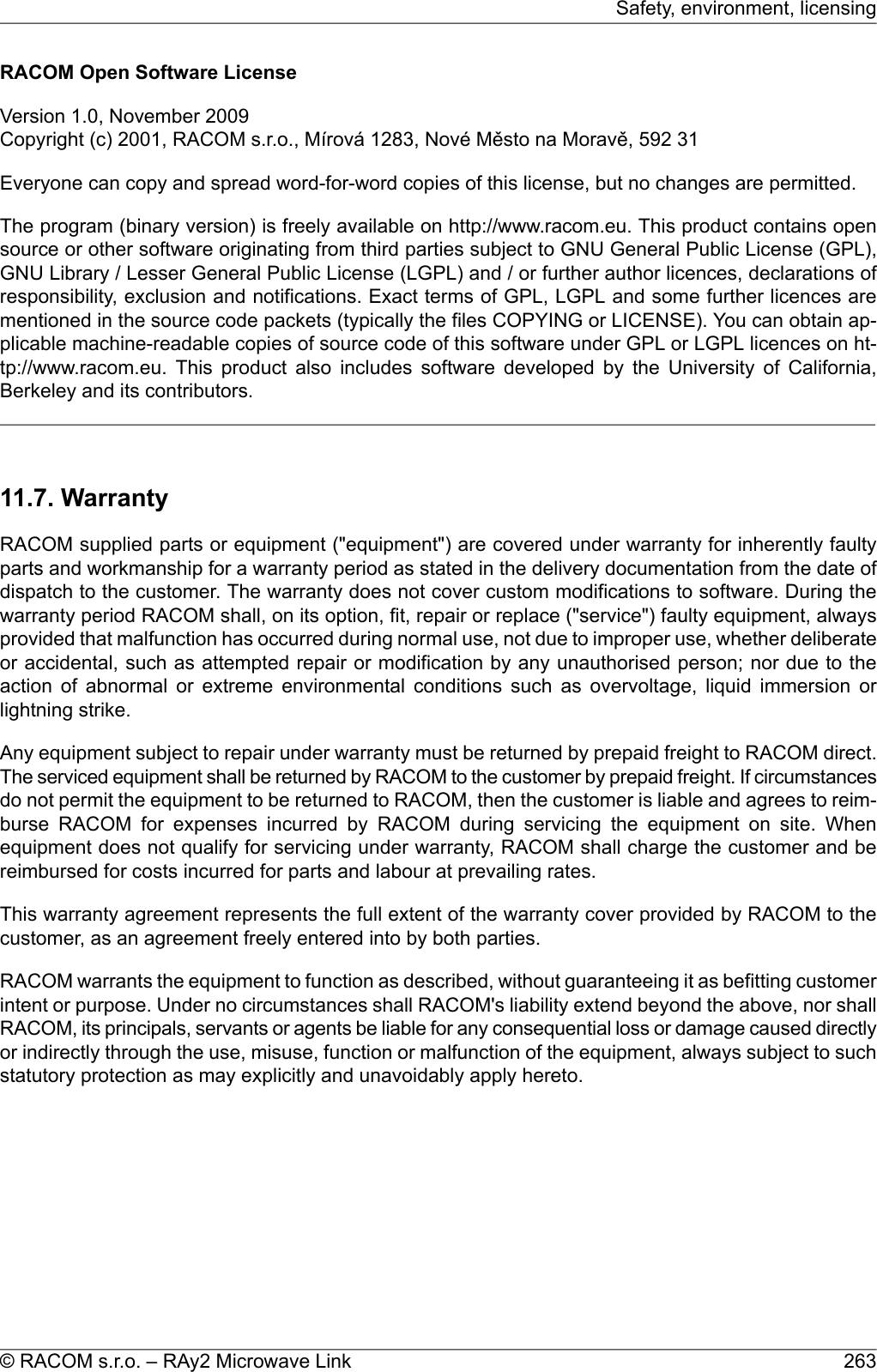
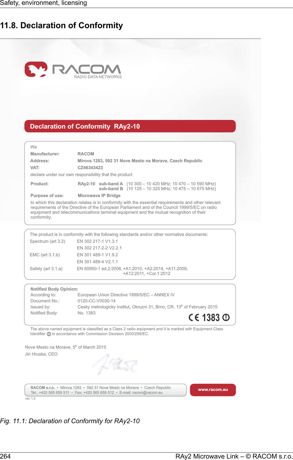
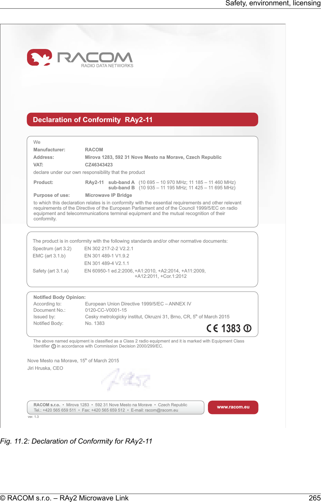
![11.9. FCC authorization of transmittersFCC verificationRAy2-11 was verified for compliance according to CFR 47 part 101 [see §101.139(a)].FCC comment -according to §101.141 and considering the low spectral efficiency the following modulations are notallowed in RAy2-11:ModulationBandwidthQPSK2.5 MHzQPSK3.75 MHzQPSK5 MHzQPSK, 16-QAM, 32-QAM10 MHzQPSK30 MHzQPSK40 MHzExcept during anomalous signal fading. During anomalous signal fading, licensees may adjust to amodulation specified in their authorization if such modulation is necessary, to allow the licensees tomaintain communications, even if the modulation does not comply with the capacity and loading require-ments -101.141 (3).FCC complianceRAy2-24 complies with CFR 47 part 15.FCC IDFCC partCodeSQT-RAY2-2415RAy2-24RAy2 Microwave Link – © RACOM s.r.o.268Safety, environment, licensing](https://usermanual.wiki/Racom/RAY2-24/User-Guide-2944903-Page-268.png)