Racom RAY2-24 ISM Transmitter User Manual RAy2 Microwave Link
Racom ISM Transmitter RAy2 Microwave Link
Racom >
User Manual

User manual
.
RAy2 Microwave Link
.
fw 2.1.x.x
3/17/2016
version 1.14
www.racom.eu
RACOMs.r.o. •Mirova1283•59231NoveMestonaMorave•CzechRepublic
Tel.:+420565659511•Fax:+420565659512•E-mail: racom@racom.eu

Table of Contents
Important Notice .................................................................................................................................. 7
Quick guide ......................................................................................................................................... 8
List of documentation ........................................................................................................................ 10
1. RAy2 – Microwave Link ................................................................................................................. 11
2. Implementation Notes ................................................................................................................... 12
2.1. Link calculation ................................................................................................................... 12
2.1.1. Free space loss calculation ..................................................................................... 12
2.1.2. Link budget calculation ............................................................................................ 12
2.1.3. Fade margin ............................................................................................................ 13
2.1.4. Rain attenuation ...................................................................................................... 13
2.1.5. Multipath fading ....................................................................................................... 16
2.1.6. Fresnel zones calculation ........................................................................................ 17
2.2. Example of microwave link design ..................................................................................... 18
3. Product .......................................................................................................................................... 21
3.1. Mounting ............................................................................................................................. 22
3.2. Connectors ......................................................................................................................... 22
3.3. Power supply ...................................................................................................................... 23
3.4. Status LEDs ....................................................................................................................... 25
3.5. Technical parameters ......................................................................................................... 25
3.6. Dimensions ......................................................................................................................... 26
3.7. Ordering codes ................................................................................................................... 27
4. Accessories ................................................................................................................................... 28
4.1. Overview ........................................................................................................................... 28
4.2. Details ................................................................................................................................30
5. Step-by-step Guide ....................................................................................................................... 36
5.1. Service access ................................................................................................................... 37
5.1.1. Menu Link settings - General ................................................................................... 38
5.1.2. Menu Link - Service access - Services ................................................................... 39
5.1.3. Menu Link - Service access - Users ........................................................................ 40
5.1.4. Menu Maintenance - Feature keys .......................................................................... 40
5.2. Basic link configuration ....................................................................................................... 40
5.3. Link test .............................................................................................................................. 40
6. Installation ..................................................................................................................................... 42
6.1. Line of sight test ................................................................................................................. 42
6.2. Antenna mounting .............................................................................................................. 42
6.2.1. Mounting methods ................................................................................................... 42
6.2.2. Mounting the FOD unit on the antenna ................................................................... 45
6.2.3. Lubrication and preservation of the antenna pivot .................................................. 49
6.2.4. Flexible waveguide .................................................................................................. 49
6.3. Connectors assembly ......................................................................................................... 50
6.4. Grounding ........................................................................................................................... 52
6.5. Start up ............................................................................................................................... 57
6.5.1. Noise on the site ...................................................................................................... 57
6.5.2. Directing antennas ................................................................................................... 57
6.5.3. Link test ................................................................................................................... 61
6.5.4. Parameters setup .................................................................................................... 61
7. Configuration ................................................................................................................................. 62
7.1. Introduction ......................................................................................................................... 62
7.2. Status bar ........................................................................................................................... 63
7.3. Status ................................................................................................................................. 65
7.3.1. Status - General ...................................................................................................... 66
3© RACOM s.r.o. – RAy2 Microwave Link

7.3.2. Status - Radio .......................................................................................................... 66
7.3.3. Status - Switch interface .......................................................................................... 68
7.3.4. Status - Service access ........................................................................................... 68
7.3.5. Status - Radio link statistics ..................................................................................... 68
7.4. Link settings ....................................................................................................................... 69
7.4.1. General .................................................................................................................... 69
7.4.2. Radio ....................................................................................................................... 70
7.4.3. Service access ........................................................................................................ 72
7.4.4. Alarms ..................................................................................................................... 80
7.5. Switch settings ................................................................................................................... 83
7.5.1. Status ...................................................................................................................... 83
7.5.2. Interface ................................................................................................................... 92
7.5.3. QoS ....................................................................................................................... 111
7.5.4. Advanced ............................................................................................................... 114
7.6. Tools ................................................................................................................................. 142
7.6.1. Maintenance .......................................................................................................... 142
7.6.2. Live data ................................................................................................................ 150
7.6.3. History ................................................................................................................... 153
7.6.4. Logs ....................................................................................................................... 157
7.6.5. Programs ............................................................................................................... 158
7.7. Help .................................................................................................................................. 162
8. Command Line Interface ............................................................................................................. 165
8.1. Connection via CLI ........................................................................................................... 165
8.1.1. Telnet ..................................................................................................................... 165
8.1.2. Putty ...................................................................................................................... 165
8.1.3. SSH ....................................................................................................................... 165
8.2. Working with CLI .............................................................................................................. 166
8.2.1. SSH keys ............................................................................................................... 167
8.2.2. Scripts .................................................................................................................... 167
8.3. Configuration with CLI ...................................................................................................... 168
8.3.1. Configuration file .................................................................................................... 168
8.3.2. Firmware upgrade ................................................................................................. 168
8.3.3. Remote unit authorization ...................................................................................... 168
9. Troubleshooting ........................................................................................................................... 170
10. Technical parameters ............................................................................................................... 172
10.1. General parameters ...................................................................................................... 172
10.1.1. Technical parameters overview ........................................................................... 172
10.1.2. Link speed ........................................................................................................... 174
10.2. Nominal frequency tables description ............................................................................ 176
10.3. RAy2-10 parameters ...................................................................................................... 177
10.3.1. Upper/Lower Limits .............................................................................................. 177
10.3.2. Radio parameters ................................................................................................ 178
10.3.3. Nominal frequencies, band 10.30 – 10.59 GHz .................................................. 181
10.3.4. Nominal frequencies, band 10.15 – 10.65 GHz .................................................. 184
10.4. RAy2-11 A,B parameters ................................................................................................ 188
10.4.1. Upper/Lower Limits .............................................................................................. 188
10.4.2. Radio parameters ................................................................................................ 189
10.4.3. Nominal frequencies, duplex 490 MHz ................................................................ 192
10.4.4. Nominal frequencies, duplex 530 MHz ................................................................ 198
10.5. RAy2-11 C,D parameters ............................................................................................... 204
10.6. RAy2-17 parameters ...................................................................................................... 205
10.6.1. Upper/Lower Limits .............................................................................................. 205
RAy2 Microwave Link – © RACOM s.r.o.4
RAy2 Microwave Link

10.6.2. Radio parameters ................................................................................................ 206
10.6.3. Nominal frequencies ............................................................................................ 209
10.7. RAy2-18 parameters ...................................................................................................... 216
10.7.1. Upper/Lower Limits .............................................................................................. 216
10.7.2. Radio parameters ................................................................................................ 217
10.7.3. Nominal frequencies ............................................................................................ 221
10.8. RAy2-24 parameters ...................................................................................................... 233
10.8.1. Upper/Lower Limits .............................................................................................. 233
10.8.2. Radio parameters ................................................................................................ 234
10.8.3. Nominal frequencies 24.00-24.25 GHz ............................................................... 237
10.8.4. Nominal frequencies 24.05-24.25 GHz ............................................................... 244
10.8.5. Nominal frequencies 24.05-24.25 GHz FCC ....................................................... 251
10.8.6. Nominal frequencies 24.00-24.15 GHz ............................................................... 255
11. Safety, environment, licensing ................................................................................................... 260
11.1. Frequency ....................................................................................................................... 260
11.2. Safety distance ............................................................................................................... 260
11.3. Professional installation .................................................................................................. 261
11.4. RoHS and WEEE compliance ........................................................................................ 261
11.5. Liability for Defects and Safety Instructions .................................................................... 262
11.6. Important Notifications .................................................................................................... 262
11.7. Warranty ......................................................................................................................... 263
11.8. Declaration of Conformity ............................................................................................... 264
11.9. FCC authorization of transmitters ................................................................................... 268
11.10. Country of Origin Declaration ....................................................................................... 269
A. Antenna dimensions ................................................................................................................... 270
B. Rain zone map ............................................................................................................................ 271
C. IP address in the PC (Windows XP) ........................................................................................... 272
D. IP address in the PC (Windows 7) .............................................................................................. 274
E. IP address in the PC (Windows 8) .............................................................................................. 276
F. SSH key generation ..................................................................................................................... 279
G. Https certificate ........................................................................................................................... 281
H. Unit block diagrams .................................................................................................................... 282
Index ................................................................................................................................................283
I. Revision History ........................................................................................................................... 287
List of Tables
2.1. Rain rate R (mm/h) ITU-R P.837 ................................................................................................ 14
2.2. Constants k, α for horizontal and vertical polarization at 10, 11, 17 and 24 GHz ...................... 15
2.3. 60 % of the 1st Fresnel zone ..................................................................................................... 18
3.1. Meaning of LED status indicators .............................................................................................. 25
3.2. Overview of antennas ................................................................................................................. 26
3.3. Ordering codes ........................................................................................................................... 27
10.1. Technical parameters ............................................................................................................. 172
11.1. Minimum Safety Distance 11 GHz .......................................................................................... 260
11.2. Minimum Safety Distance 24 GHz .......................................................................................... 261
5© RACOM s.r.o. – RAy2 Microwave Link
RAy2 Microwave Link

6

Important Notice
Copyright
© 2014 RACOM. All rights reserved.
Products offered may contain software proprietary to RACOM s. r. o. (further referred to under the ab-
breviated name RACOM). The offer of supply of these products and services does not include or infer
any transfer of ownership. No part of the documentation or information supplied may be divulged to
any third party without the express written consent of RACOM.
Disclaimer
Although every precaution has been taken in preparing this information, RACOM assumes no liability
for errors and omissions, or any damages resulting from the use of this information. This document or
the equipment may be modified without notice, in the interests of improving the product.
Trademark
All trademarks and product names are the property of their respective owners.
Important Notice
• Due to the nature of wireless communications, transmission and reception of data can never be
guaranteed. Data may be delayed, corrupted (i.e., have errors), or be totally lost. Significant delays
or losses of data are rare when wireless devices such as the RAy2 are used in an appropriate
manner within a well‐constructed network. RAy2 should not be used in situations where failure to
transmit or receive data could result in damage of any kind to the user or any other party, including
but not limited to personal injury, death, or loss of property. RACOM accepts no liability for damages
of any kind resulting from delays or errors in data transmitted or received using RAy2, or for the
failure of RAy2 to transmit or receive such data.
• Under no circumstances is RACOM or any other company or person responsible for incidental,
accidental or related damage arising as a result of the use of this product. RACOM does not provide
the user with any form of guarantee containing assurance of the suitability and applicability for its
application.
• RACOM products are not developed, designed or tested for use in applications which may directly
affect health and/or life functions of humans or animals, nor to be a component of similarly important
systems, and RACOM does not provide any guarantee when company products are used in such
applications.
7© RACOM s.r.o. – RAy2 Microwave Link
Important Notice
Quick guide
Accessing units
— Default IP addresses: 192.168.169.169/24 (L unit) Username: admin
192.168.169.170/24 (U unit) Password: admin
Set computer IP address within the IP range 192.168.169.1-255.
— Web browser access – https://192.168.169.169 (L unit)
or https://192.168.169.170 (U unit).
Accept the https security certificate issued by RACOM.
— If the units are linked to each other, the status indicator in management interface states “OK”
and status LED “AIR” lights green. If not, utilize the antenna alignment. (see pict. 11)
Configuration and backup of basic parameters
Set bandwidth, TX/RX channel, TX modulation, RF power, IP addresses (do not use
the default ones), Access channels (ssh, https, …).
Reboot both units and check the link status (to verify that the parameters are saved correctly)
Backup the configuration in the Tools – Maintenance – Backup – Settings menu.
Store the backup file to your PC.
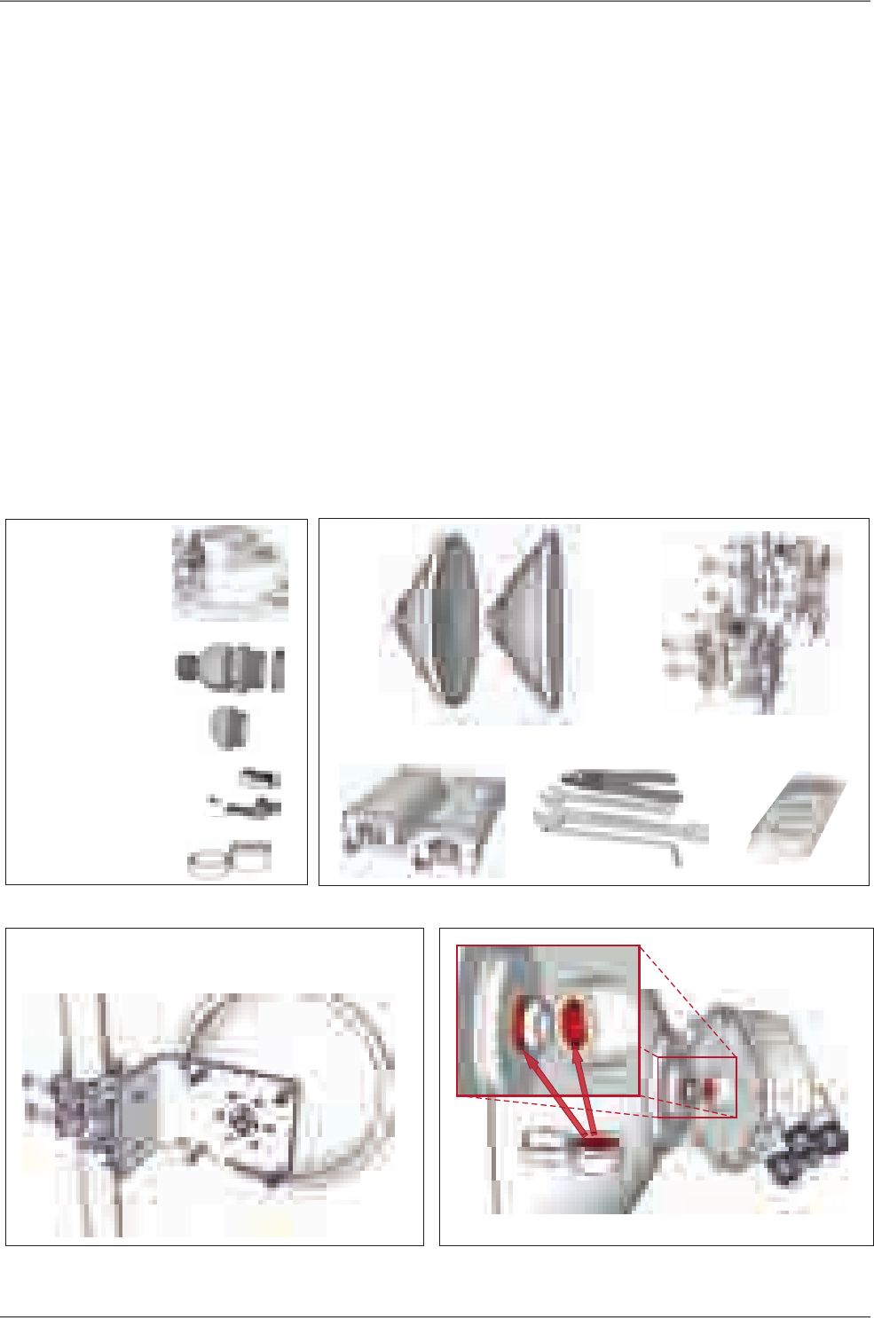
2. Accessories
Voltmeter
Antenna brackets
Antennas
Power supply Required tools
1. Delivered items
RAy2
Plugs
Grease
Bushings
7×
2×
1×RJ45
1×
1×DC
3×3×
Connectors
4. RAy unit and antenna lubrication
Grease
Antenna RAy2
3. Bracket and antenna mounting
Mounting
- right sided (pictured below)
- left sided
RAy2 Microwave Link – © RACOM s.r.o.8
Quick guide
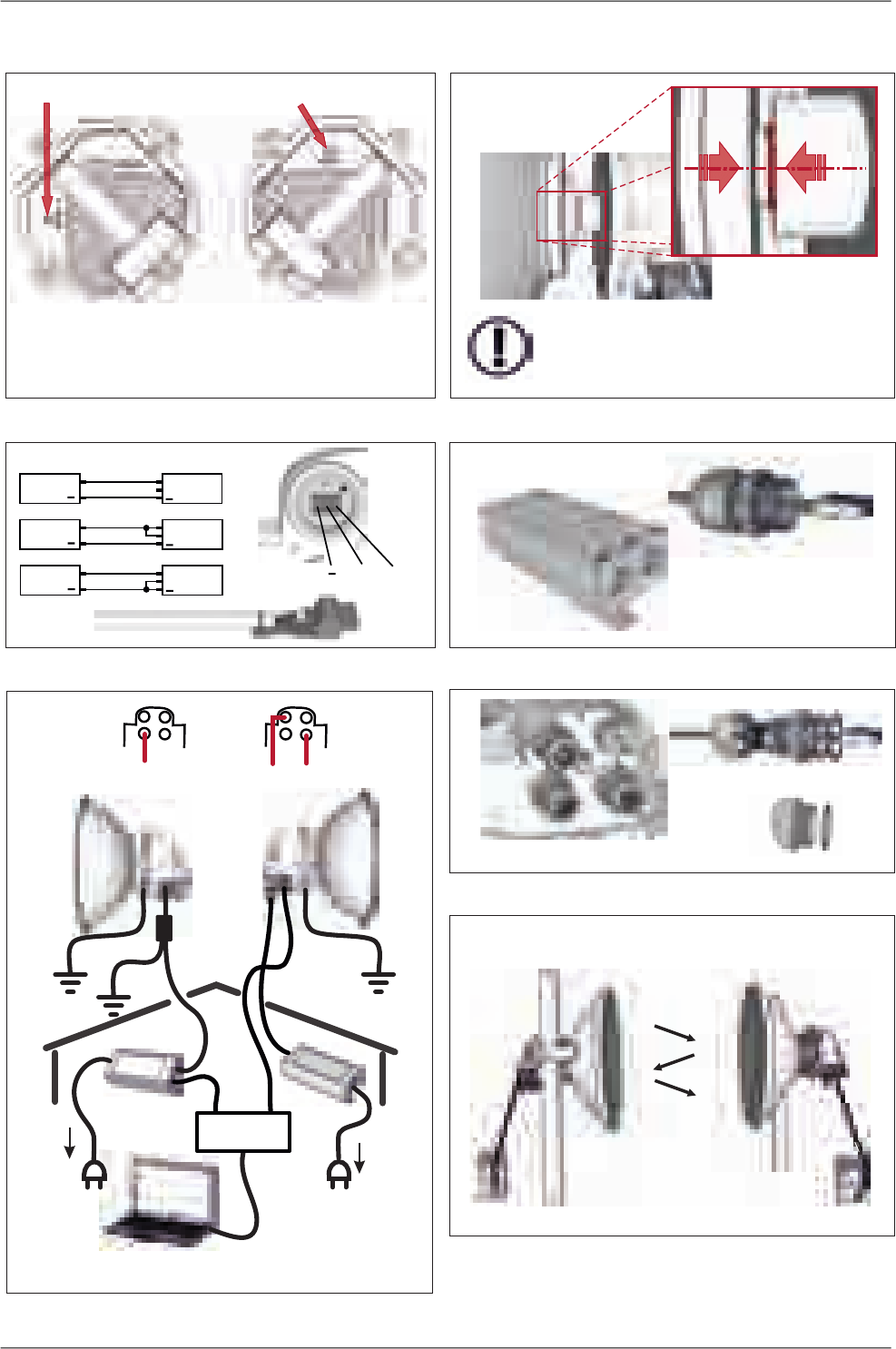
6. Unit installation
Check the correct O – ring placement
on the antenna
Ensure the antenna and unit are carefully aligned
Do not use excessive force!
5. Unit polarization
Horizontal Vertical
- the same polarization
for both units
RAy2-10, RAy2-11 RAy2-17, RAy2-24
- cross polarization
- one side – horizontal
- the other side – vertical
8. Power - PoE
Power supply
RJ45
7. Power - DC
DC cable
GND +
+
+
+
DC
DC
DC
+
+
+
RAy2
RAy2
RAy2
GND
GND
GND
10. Sealing
Bushing
Plug
Seal unit interfaces with bushings and plugs
9. Power grounding and connections
AC 230 V
AC 230 V
PoE
PoE + Eth
DC
SWITCH
DC fibre
Units must be grounded
For surge protection - see user manual
11. Antenna alignment
Hint: Set QPSK, CS 7 MHz, max. TX power
Best RSS = minimum voltage in range 0–2 V
1
3
2
4
Step-by-step alignment – see user manual
ver. 1.7
9© RACOM s.r.o. – RAy2 Microwave Link
Quick guide

List of documentation
User manuals
■Microwave Link RAy2 - this document
User manual RAy2-10, RAy2-11, RAy2-17, RAy2-24
■Microwave Link RAy11, 17, 241
User manual RAy11, RAy17, RAy24
■Microwave Link RAy102
User manual RAy10
Datasheets
■RAy2 - Datasheet3
■RAy - Datasheet4
■RAy - SCADA Backbone5
Application notes
■RAy - Application notes6
Contents of the box
• 2 pc RAy2
• 2 pc Cable bushing set, connectors
• 1 pc Grease marked "SILIKONOVE MAZIVO"
1http://www.racom.eu/eng/products/m/ray17/index.html
2http://www.racom.eu/eng/products/m/ray/index.html
3http://www.racom.eu/download/hw/ray/free/eng/00_letaky/datasheet_RAY2_en.pdf
4http://www.racom.eu/download/hw/ray/free/eng/00_letaky/datasheet_RAY_en.pdf
5http://www.racom.eu/download/hw/ray/free/eng/00_letaky/leaflet_RAY_scada_en.pdf
6http://www.racom.eu/download/hw/ray/free/cz/01_ray/RAy-AppNote-en.pdf
RAy2 Microwave Link – © RACOM s.r.o.10
List of documentation

1. RAy2 – Microwave Link
The microwave link RAy2 is designed as a high-speed point-to-point wireless bridge for data transmission
under the latest requirements of modern wireless transmission equipment.
RAy2 works with an ethernet interface and can be used in backhaul networks as well as a last-mile
terminal.The design of microwave link RAy2 reflects effort on meeting the strictest criteria of ETSI
standards, particularly for durability against interference, high receiver sensitivity and high output power
to achieve maximum link distance. The native gigabit Ethernet interface is able to cope with full speed
user data throughput at low latency. High availability of the link (up to 99.999%) is able to be achieved
using hitless Adaptive coding and modulation. RAy2 microwave links can also be operated as a Short
Range Device (SRD).
The link properties can be summarised as:
• High data throughput
• Spectrum effeciency
• Robustness
• Security - cofiguration via http, https, ssh
• User friendly interface, advanced diagnostics
Key technical features see Chapter 10, Technical parameters
Note
Operation of the RAy2-xx is described in this user manual.
Operation of the RAy11, RAy17 and RAy24 is described in User Manual RAy11,17,241.
Operation of the RAy10 is described in the RAy10 User Manual2.
1http://www.racom.eu/eng/products/m/ray17/index.html
2http://www.racom.eu/eng/products/m/ray/index.html
11© RACOM s.r.o. – RAy2 Microwave Link
RAy2 – Microwave Link

2. Implementation Notes
2.1. Link calculation
Before a microwave link can be installed, an analysis and calculation of the microwave link must be
made first. The analysis should take place before the site survey itself to get a clear idea about the di-
mensions of the antennas. The analysis consists of the following steps:
• Free space loss calculation
• Link budget calculation
• Rain attenuation
• Multipath fading
• Fade margin
• Fresnel zones calculation
This chapter explains the individual steps and an example of link design is given at the end.
NOTE - For quick reference you can use the calculator on www.racom.eu1
2.1.1. Free space loss calculation
As the electromagnetic waves travel through open space they are attenuated. This attenuation is de-
scribed as Free-space Loss. The loss depends on the distance travelled by signal and its frequency.
Longer distance and higher frequency both mean greater attenuation. Free-space loss can be calculated
thus:
FSL = 32.44 + 20log f+ 20log D
Where:
FSL free-space loss (dB)
ffrequency of the emitted signal (MHz)
Dlength of the link (km)
2.1.2. Link budget calculation
The goal is to design a link producing a received signal stronger than the receiver's sensitivity at the
required BER (typically 10-6). Since every radio signal in earth atmosphere is subject to fading, some
difference between received signal level under normal circumstances and receiver sensitivity is needed
to serve as a fade margin. The minimum value of fade margin can be calculated from the requirement
for link availability (e.g. 99.999% of the time). The required margin depends on the length of the link
as well as other factors such as rain attenuation, diffraction and multipath propagation.
If we ignore the additional loss along the path, the received signal strength can be calculated using the
formula for signal propagation in free space as follows:
PR=PT+GT+GR-FSL
Where
1http://www.racom.eu/eng/products/microwave-link.html#calculation_obsah
RAy2 Microwave Link – © RACOM s.r.o.12
Implementation Notes

PRreceived power level (dBm)
PTtransmitted power (dBm)
GTtransmitting antenna gain (dBi)
GRreceiving antenna gain (dBi)
FSL free space loss (dB)
PRmust be:
PR>PS
Where:
PSreceiver sensitivity (dBm)
The receiver’s sensitivity defines the minimum level of the received signal at which the receiver is able
to process the signal without losses or affecting the transmitted data (for BER better then 10-6).
2.1.3. Fade margin
Determining sufficient fade margin is the most important step in microwave link design. If the margin
is too small, the link will be unstable – as a result, sufficient availability of the link or quality of the
provided services cannot be guaranteed. On the other hand, unnecessarily large margin makes the
link more expensive (higher performance, larger and more expensive antennas) and increases the
cost of creating the microwave link.
The following paragraphs describe the two most significant types of signal strength loss – rain and
multipath attenuation, which are the most frequent along with free space loss. Mutual relation between
rain and multipath attenuation rules out the possibility that the link could be affected by both types of
attenuation at the same time – these types of attenuation do not add up. To determine the fade
margin it is necessary to calculate both rain and multipath attenuation. The larger of the two types of
attenuation determines the value of fade margin. In areas with high precipitation, rain attenuation can
be expected to be more prominent. By contrast, links located in drier climates and little inclination, will
suffer more from multipath attenuation.
2.1.4. Rain attenuation
For frequencies of about 10 GHz rain attenuation starts to become increasingly effective. Precipitation
is not identical in all areas which is why ITU released a recommendation Rec. ITU-R PN.837-1 for
splitting the world into 15 regions according to precipitation intensity see Fig. 2.1, for more detail Ap-
pendix B, Rain zone map. In the areas with higher precipitation greater rain attenuation must be expected
and a greater signal fade margin must be established; see the calculation of link availability.
The following properties are inherent to rain attenuation:
• It increases exponentially with rain intensity
• It becomes significantly larger as the distance travelled increases (>10 Km)
• Horizontal polarization causes greater rain attenuation than vertical polarization
• Rain outage increases dramatically with frequency and path length
13© RACOM s.r.o. – RAy2 Microwave Link
Implementation Notes

Fig. 2.1: Rain zone map, based on Rec.ITU-R PN.837-1
Rain attenuation can be calculated using ITU-R outage model, which consists of the following:
Obtain the rain rate R0.01 exceeded for 0.01 per cent of the time (with an integration time of 1 min).
R0.01 values are defined for 15 rain zones and different time percentages and they are given in ITU-R
Recommendation P.837.
Tab. 2.1: Rain rate R (mm/h) ITU-R P.837
QPNMLKJHGFEDCBA
Percentage
of time (%)
1412542158231.70.62.10.70.5<0.11.0
4934151174213474.52.44.52.820.80.3
7265352215122010128685320.1
96105654033232818201512139650.03
11514595636042353230282219151280.01
14220014095105704555455441292621140.003
1702501801201501005583657870424232220.001
Compute specific attenuation γR(dB/km) for the frequency, polarization, specific rain rate using ITU-R
recommendation P.838. Rain attenuation for rain rate γR0.01 can be calculated as follows:
γR0.01 = kh,v .R0.01αh,v
where:
RAy2 Microwave Link – © RACOM s.r.o.14
Implementation Notes
kh,v, αh,v constants for horizontal and vertical polarization. Constants are slightly different for each
polarization, see next table according to ITU-R P.838
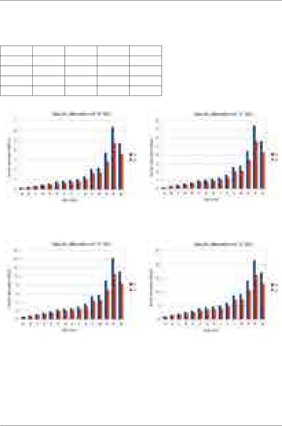
Tab. 2.2: Constants k, α for horizontal and vertical polarization at 10, 11, 17 and 24 GHz
αv
kv
αh
kh
1.220.011.260.0110 GHz
1.160.021.210.0211 GHz
1.010.071.090.0617 GHz
0.960.141.010.1424 GHz
Fig. 2.2: Attenuation for 10 GHz,
polarization H, V
Fig. 2.3: Attenuation for 11 GHz,
polarization H, V
Fig. 2.4: Attenuation for 17 GHz,
polarization H, V
Fig. 2.5: Attenuation for 24 GHz,
polarization H, V
Fig. 2.2 shows that rain attenuation is greater for horizontal polarization. In regions with higher precip-
itation the difference in attenuation is more marked. The microwave links RAy17 and RAy24 use both
polarizations, hence the need to consider the worse of the two, i.e. horizontal polarization. When ACM
15© RACOM s.r.o. – RAy2 Microwave Link
Implementation Notes

is active we recommend using horizontal polarization in the direction with lower data traffic (typically
up-link).
2.1.5. Multipath fading
Multipath fading is another dominant fading mechanism. A reflected wave causes a phenomenon known
as multipath, meaning that the radio signal can travel multiple paths to reach the receiver. Typically,
multipath occurs when a reflected wave reaches the receiver at the same time in opposite phase as
the direct wave that travels in a straight line from the transmitter.
Multipath propagation gives rise to two kinds of signal degrading effects, i.e., flat fading and frequency
selective fading. Flat fading is a reduction in input signal level where all frequencies in the channel of
interest are equally affected and is dependent on path length, frequency, and path inclination. In addition,
it is strongly dependent on the geoclimatic factor K.
To calculate the probability of outage due to multipath propagation of microwave links the ITU-R
probability model can be used which describes a single frequency (or narrowband) fading distribution
suitable for large fade depths A in the average worst month in any part of the world (based on ITU-R
P.530-14). The calculation for detailed link design is given as follows [1]:
P0=Kd3.4(1+|εP|)-1.03f0.8×100.00067hL-A/10
where:
dlink distance (km)
ffrequency (GHz)
hLaltitude of lower antenna (m)
Afade depth (dB)
K is geoclimatic factor and can be obtained from:
K= 10-4.6-0.0027dN1
The term dN1 is provided on a 1.5° grid in latitude and longitude in ITU-R Recommendation P.453.
The data are available in a tabular format and are available from the Radiocommunication Bureau
(BR). E.g. in Central Europe the values dN1 range from -242 to -362.
From the antenna heights heand hr(meters above sea level), calculate the magnitude of the path in-
clination │εP│ (mrad) using the following expression:
where:
dlink distance (km)
hr, heantenna heights above sea level (m)
RAy2 Microwave Link – © RACOM s.r.o.16
Implementation Notes
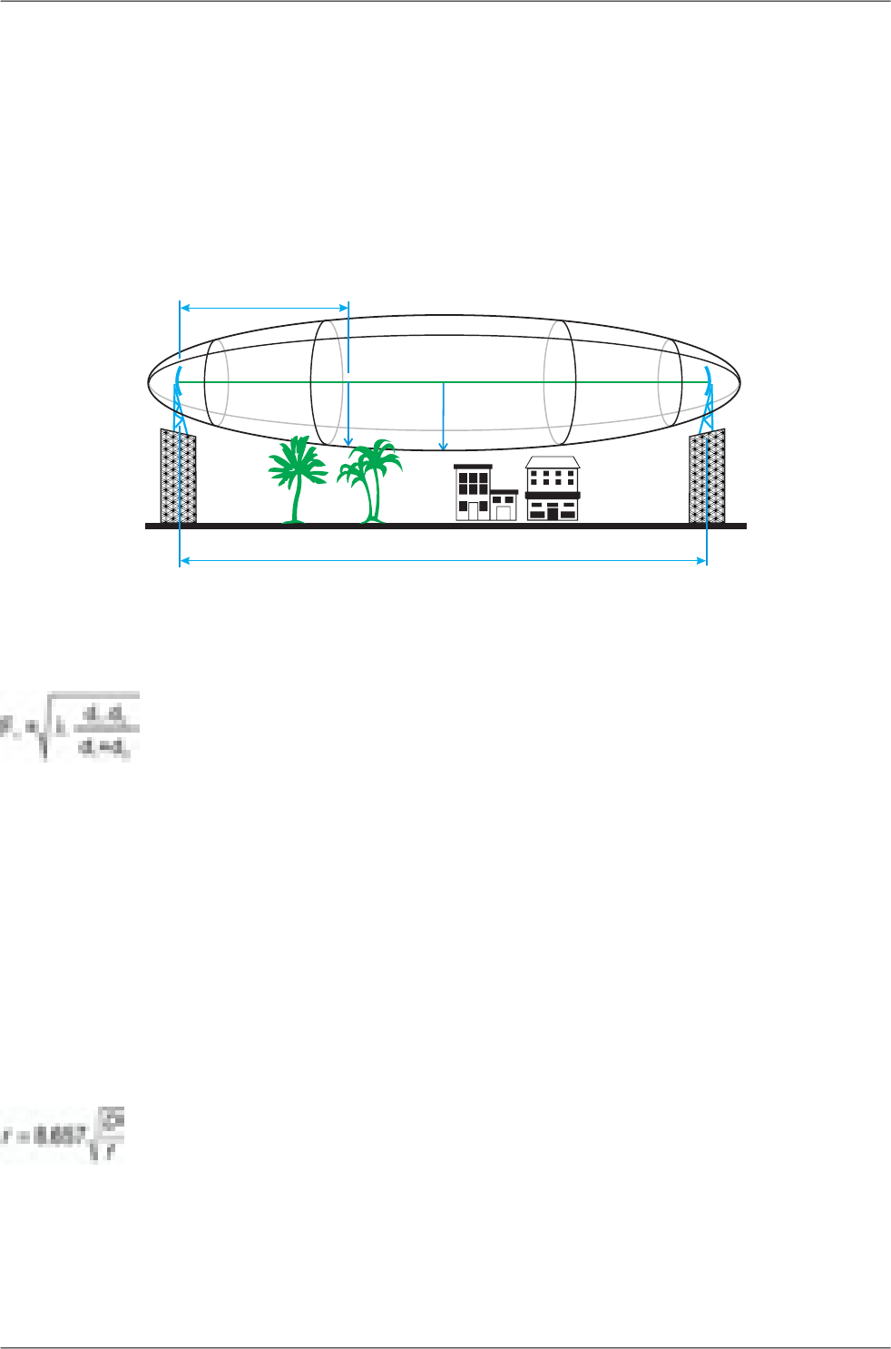
2.1.6. Fresnel zones calculation
The position of obstacles between points of the bridge can significantly influence the quality of the mi-
crowave link. The radio signal doesn't only radiate along the line of sight, but also in the area around
it, i.e. in the so-called 1st Fresnel zone. Within this zone 90 % of the energy is transmitted between the
transmitter and receiver antenna. This space has the shape of an ellipsoid. If it is disturbed the link has
poorer transmission properties and a higher quality antenna is required. For this reason the position
of the antenna can be just as important as its height above ground. 60 % of the 1st Fresnel zone is
considered as the most important.
r
D
F1
d1
× ×
Fig. 2.6: Fresnel zone
The general equation for calculating the first Fresnel zone radius at any point P in between the endpoints
of the link is the following:
Where:
F1first Fresnel Zone radius in metres
d1distance of P from one end in metres
d2The distance of P from the other end in metres
λ wavelength of the transmitted signal in metres
The cross sectional radius of each Fresnel zone is the highest in the center of link, shrinking to a point
at the antenna on each end. For practical applications, it is often useful to know the maximum radius
of the first Fresnel zone. From the above formula, calculation of the first Fresnel zone can be simplified
to:
where:
rmax radius of first Fresnel zone (m)
reducing the radius to 60% get values listed in the following table that define the space particularly
sensitive to the presence of obstacles
17© RACOM s.r.o. – RAy2 Microwave Link
Implementation Notes
Dtotal link distance (km)
ffrequency (GHz)
Tab. 2.3: 60 % of the 1st Fresnel zone
Radius of zone r for frequencyLength of link D
24 GHz17 GHz11 GHz
0.75 m0.89 m1.10 m0,5 km
1.06 m1.25 m1.56 m1 km
1.50 m1.77 m2.21 m2 km
2.12 m2.50 m3.13 m4 km
2.60 m3.07 m3.84 m6 km
3.00 m3.54 m4.43 m8 km
3.35 m3.96 m4.95 m10 km
4.10 m4.85 m6.06 m15 km
4.74 m5.60 m7.00 m20 km
11.07 m50 km
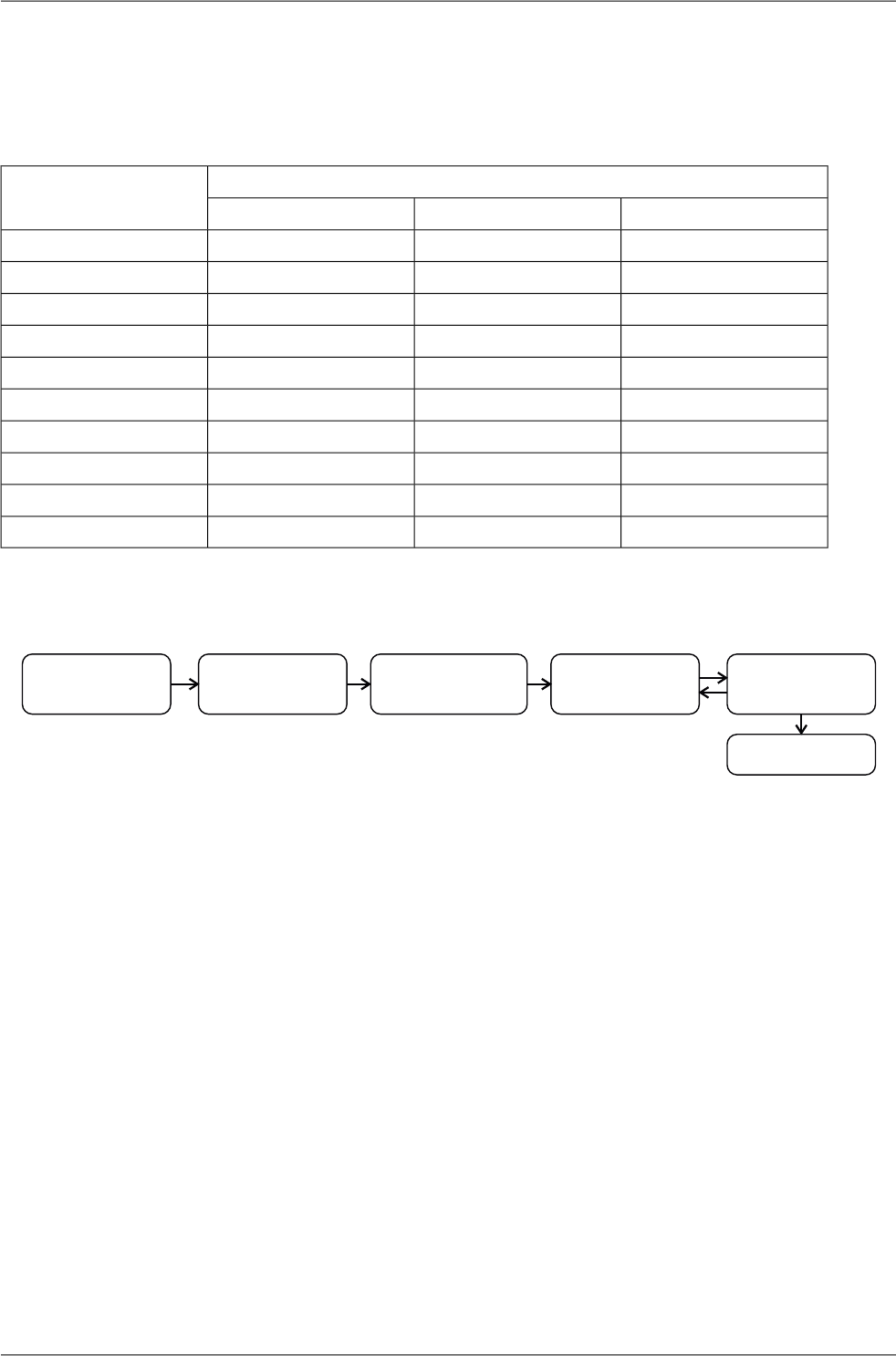
2.2. Example of microwave link design
Stanovení
požadavků
Výpočet ú tlumu při
šíření prostorem
Výpo
št
čet ú niku
vlivem de ěa
vícecestným šířením
Volba vysílacího
výkonu antén Kalkulace spoje
Výsledek
1. 2. 3. 4. 5.
Fig. 2.7: Design flowchart
Step 1 - Requirements Determination
Link parameters:
Link distance: 4 km
First antenna height above sea level: 295 m
Second antenna height above sea level: 320 m
Location: Central Europe (rain zone H, refraction gradient dN1= −300)
Transmission requirements:
Required data rate: >160 Mbps
Required availability: 99.99 %
RAy parameters:
17 GHz
161 Mbps -> Modulation 16QAM; BW=56 MHz; PS(BER 10-6)= −79 dBm
Tx power +5 dBm (max. Tx power)
Antenna gain:
RAy2 Microwave Link – © RACOM s.r.o.18
Implementation Notes

30 cm ... 32.2 dBi
60 cm ... 37.8 dBi
99 cm ... 42 dBi
Step 2 - Free space loss calculation
FSL = 32.44 + 20log f+ 20log D= 32.44 + 20log17.2·103+ 20log4 = 129.1 dB
Step 3a - Rain attenuation
For 99.99% availability in rain zone B the rain rate is R0.01=32 (see Fig. 2.1)
For f=17 GHz kh=0.06146; αh=1.0949; kv=0.06797; αv=1.0137
Vertical polarization:
γR0.01 = kv.Rαv0.01 = 0.07 · 321.01 = 2.32 dB/km => for 4km distance 9.3 dB
Horizontal polarization:
γR0.01 = kh.Rαh0.01 = 0.06 · 321.09 = 2.62 dB/km => for 4km distance 10.5 dB
Step 3b - Attenuation due to multipath propagation
We have to find required fade margin for reliability of the link 99.99 percent.
Path inclination:
The percentage of time that fade depth A (dB) is exceeded in the average worst month is calculated
as:
P0=Kd3.4(1+|εP|)-1.03f0.8×100.00067hL-A/10
P0=10-4.6-0.0027×(-300)×43.4(1+|6.25|)-1.0317.20.8×100.032×10-0.00067×295-A/10
P0=0.022871×10-0.19765-A/10
For reliability 99.99% is P0=0.01 we get exponential function for A:
A= -0.19765 - 10log(0.01/0.022871) = 3.4 dB
The minimum fade margin required to suppress multipath fading on this link would be 4 dB.
Step 4 - Choice of Tx power and antennas
Step 5 - and Link budget calculation
Calculation in steps 3a and 3b determines the minimum fade margin required for stable link operation
as 11 dB (rain attenuation is dominant). If you use the maximum performance of antenna with dia-
meter of 30 cm, complete the radio formula as follows:
PR=PT+GT+GR−FSL = 5 + 32.2 + 32.2 − 129.1 = −59.7 dB
Fade margin:
A= |PS|−|PR| = 79 − 59.7 = 19.3 dB
The resulting fade margin is larger than the required 11 dB. Current legislation in the Czech Republic
allows maximum EIRP of +20, i.e. the sum of transmit power and antenna gain at the transmitter
can be 20 dB at the most. For 99cm antennas, TX power can be up to 20 - 42 = -22 dB, the resultant
equation is as follows:
PR=PT+GT+GR−FSL = -22 + 42 + 42 − 129.1 = −67.1 dB
19© RACOM s.r.o. – RAy2 Microwave Link
Implementation Notes

Fade margin:
A= |PS|−|PR| = 79 − 67.1 = 11.9 dB
Fade margin is now only 12 dB which corresponds to link availability > 99.99% of the time in a year.
Technical literature often gives the minimum fade margin of 20 dB. For very long links (more than
10 km) fade margin will, indeed, be approximately 20 dB. For shorter links, however, such large
margin is not necessary. It is helpful to first conduct the calculation above to receive an idea of the
attenuation affecting the link.
The result
To achieve the required transmission capacity and link availability for link distance of 4 km, transmit
power -22 dBm and 99 cm antennas were selected for both sides of the link.
Sources for Chapter Chapter 2, Implementation Notes:
[1] Lehpamer, H.: Microwave transmission network, Second edition, ISBN: 0071701222, McGraw-Hill
Professional, 2010.
ITU-R recommendation used:
• ITU-R P.453-10 – The radio refractive index: its formula and refractivity data
• ITU-R P.530-14 – Propagation data and prediction methods required for the design of terrestrial
line-of-sight systems
• ITU-R P.837-1 and 6 – Characteristics of precipitation for propagation modelling
• ITU-R P.838-3 – Specific attenuation model for rain for use in prediction methods
• ITU-R P.310, ITU-R P.526, ITU-R P.676, ITU-R P.834, ITU-R P.835
RAy2 Microwave Link – © RACOM s.r.o.20
Implementation Notes

3. Product
RAy2 microwave links enable transmissions in both bands requiring license fees and those that are
free. They work as a point-to-point link in a full duplex setting with transfer speeds of up to 360 Mbps.
Bandwidth can be configured from 1.75 up to 56 MHz. Modulation can be fixed or adaptive and can
be adjusted from QPSK to 256QAM. RAy2 microwave links can also be operated as a Short Range
Device (SRD).
Fig. 3.1: RAy2 – Microwave link
The link is formed by two FOD (Full Outdoor) units. In the case of links operating in the RAy2-17 and
RAy2-24 bands, both units have identical hardware. In the case of links operating in licensed bands,
one unit (labeled L) is transmitting in the Lower and receiving in the Upper part of the band. The other
unit (labeled U) is operating vice versa.
RAy2 links require the use of external parabolic antennas. Parabolic antennas from different producers
are available.
Cross polarization - valid only for links operating in the RAy2-17 and RAy2-24 bands:
One side of the link uses one polarization for transmission (e.g. horizontal) and the opposite polarization
for receiving (e.g. vertical). The other side of the link is turned by 90°. It therefore transmits and receives
using opposite polarizations with respect to the other unit.
21© RACOM s.r.o. – RAy2 Microwave Link
Product

3.1. Mounting
Fig. 3.2: RAy2 Microwave link – antenna and FOD unit
The antenna is attached to the mast using a holder adjustable in two planes. The RAy2 unit is then
mounted on the antenna.
There are two possible mounting positions – for horizontal and vertical polarization. Installation and
adjustment of the holder is described in the Section 6.2, “Antenna mounting”.
Note
The RAy2-10 and RAy2-11 units must be mounted with the same polarization while the
units RAy2-17 and RAy2-24 must be mounted with reverse polarity, see Cross polarization.
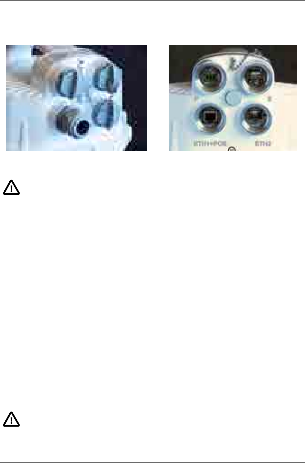
3.2. Connectors
Each unit is equipped with the following interfaces:
■ ETH1+POE – Gigabit metallic Ethernet port. This port is capable of powering the unit with any
Power over Ethernet power source working according to IEEE 802.3at standard.
■ ETH2 – Slot for user exchangeable SFP module. A wide range of optical modules is available. Both
single or dual mode transceivers can be used. An SFP module with metallic RJ45 interface can
also be used.
The SFP status LED is located just next to the slot.
■ P – DC power connector.
HW button for service purposes.
■ S – USB service connector.
RSS voltage output connectors.
Important
It is strongly recommended to use a high quality SFP module. The SFP modules listed in
Accessories are thoroughly tested by RACOM and are guaranteed to function with RAy2
units. It is possible to use any other SFP module, but RACOM cannot guarantee they will
be completely compatible with RAy2 units.
RAy2 Microwave Link – © RACOM s.r.o.22
Product
The SFP status LED function: The LED status is controlled directly from the SFP module. Its function
is specific for each SFP module. The typical behaviour is an indication of the received signal strength.
Should the signal be in the proper power range (not too strong and not too weak), the LED is shining.
Fig. 3.3: Connectors covered Fig. 3.4: Connectors uncovered
Important
It is recommended that the ETH cable should be grounded at both ends of the connection.
For example, the connector CON-RJ45-UBNT-CAT6 and ETH socket on the control panel
should have a grounded sheath as should the connection to the RAy2 unit.
All bushings and plugs (including the original plugs in the ports) must be fitted with O-rings
and carefully tightened. Otherwise, the unit is not protected against moisture intake and can
not offer guaranteed functionality.
For detailed description see Connectors and Start up.
3.3. Power supply
The microwave unit can be powered either by PoE or a DC power source:
•Standard PoE plus (IEEE 802.3at) power source connected to the “ETH1+POE” connector.
Supported voltage range is 40 — 60 V, distances up to 100 m. Internal RJ45 pins wiring is :
○ (V+) ... 1,2,4,5
○ (V-) ... 3,6,7,8
It is possible to use all 8 pins or only 4 pins. Use:
○ either 4,5 (V+) and 7,8 (V-)
○ or 1,2 (V+) and 3,6 (V-)
○ or both simultaneously
•Any kind of DC power source connected to “P” 3-pin connector.
Supported voltage range is 20 — 60 V.
Important
The microwave unit doesn't support a combination of both power supplies. Only one power
supply can be connected at any one time.
23© RACOM s.r.o. – RAy2 Microwave Link
Product
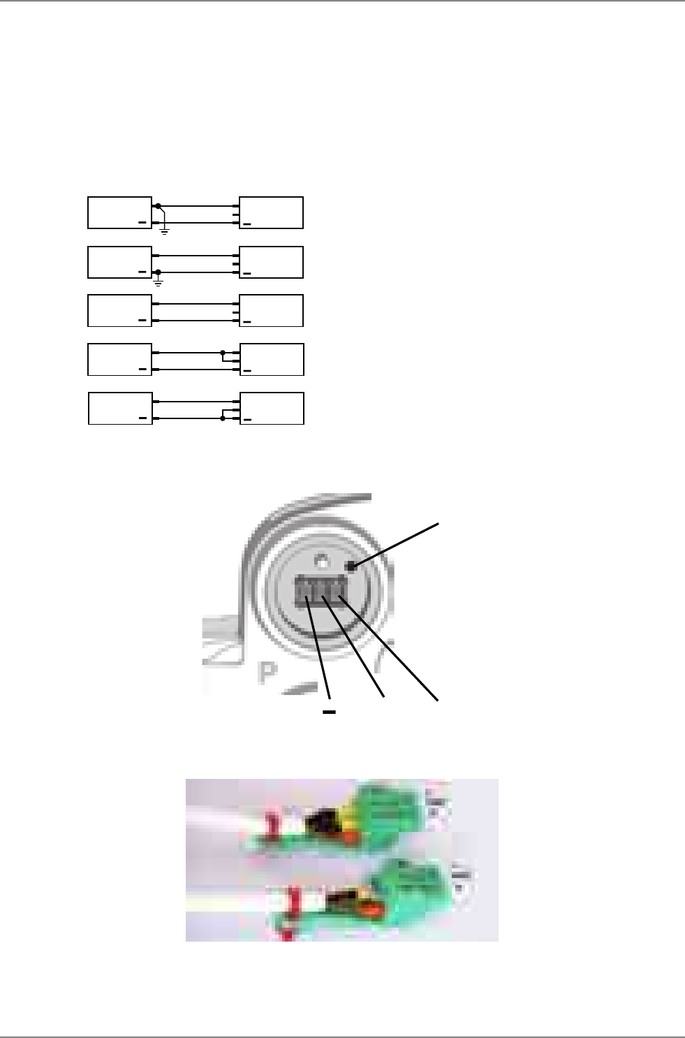
The internal DC power source uses galvanic separation. If the galvanic separated power source is
used and the DC power line needs to be grounded (either positive or negative wire), the middle pin of
the 3-port DC connector can be used to make a connection between ground and the respective power
wire, see Grounding options (d),(e). If grounding is required it should only be made in one of the following
ways: on the DC power source side or using the 3-port DC connector plugged into the unit.
The next figure shows all available grounding options. We recommend the use of a galvanic separated
power source and no additional DC grounding - see Fig. 3.5, “Grounding options” version c).
+
DC +RAy2
GND
+
DC +RAy2
GND
+
DC +RAy2
GND
+
DC +RAy2
GND
+
DC +RAy2
GND
a)
b)
c)
d)
e)
Fig. 3.5: Grounding options
GND +
HW button
Fig. 3.6: Power supply connector 1
Fig. 3.7: Power supply connector 2
RAy2 Microwave Link – © RACOM s.r.o.24
Product

3.4. Status LEDs
Fig. 3.8: Status LEDs
Tab. 3.1: Meaning of LED status indicators
FunctionColourDiode
Permanently lit: AIR link OKGreen
AIR Permanently lit: AIR LOSS, loss of connectivityRed
Permanently lit: system OK
Permanently lit: together with SYS Red - unit is starting
Flashing regularly: HW button pushed on the unit running;
factory defaults in progress;
Firmware writing in progress. DO NOT POWER OFF !!
Green
SYS
Permanently lit: together with SYS Green - unit is starting;
serious system error
Flashing regularly: HW button just pressed
Flashing intermittently: unit in the service Linux
Red
ETH1 port
Flashing regularly: Auto Negotiation in progress
Flashing irregularly: Link Activity 10/100/1000
Permanently lit: Link 10/100/1000
Green
ETH ETH2 port
Flashing regularly: Auto Negotiation in progress
Flashing irregularly: Link Activity 10/100/1000
Permanently lit: Link 10/100/1000
Orange
Flashing regularly 500 ms on / 500 ms off
Flashing intermittently 50 ms on / 950 ms off
Flashing irregularly by passing frames
3.5. Technical parameters
Basic technical parameters are stated in chapter Technical parameters.
25© RACOM s.r.o. – RAy2 Microwave Link
Product
3.6. Dimensions
Communication unit ODU
Outer size 244 x 244 x 157 mm•
Weight RAy2-10 — 2.8 kg•
• RAy2-11 — 2.8 kg
• RAy2-17 — 2.5 kg
• RAy2-24 — 2.5 kg
Diameters of supplied antennas
RAy2 units are ready for direct mounting to Jirous1Class 2 antennas.
Individual datasheets are accessible here2.
Tab. 3.2: Overview of antennas
24 GHz17 GHz10, 11 GHz
gaindiametergaindiametergaindiameter
36.8 dBi40 cm34.8 dBi40 cm29.0 dBi38 cm
41.7 dBi68 cm38.6 dBi68 cm35.5 dBi65 cm
44.0 dBi90 cm41.0 dBi90 cm37.5 dBi90 cm
46.6 dBi120 cm43.7 dBi120 cm41.0 dBi120 cm
Andrew (Class 2 or 3) or Arkivator antennas can also be used but require an antenna mounting kit.
Flexible waveguide is a general-purpose option for any antenna usage.
Name plate
The plate contains name, bar code record, CE label, etc.:
• Type – RAy2 product line identification
• Code – detailed identification of the unit type (for details see Section 3.7, “Ordering codes”)
• S/N – serial number, MW link consists of two separated units with two different serial numbers
• QR code - www link to the latest version of the User manual
• Power DC supply connector polarity marks
uw
S/N: 10218446
Type:
RAy2-24
Code:
RAy2-24
TX/RX: 24.000-24.250 GHz/24.000-24.250 GHz
PoE IEEE 802.3at www.racom.eu
20-60V max.1.5A Made in Czech Republic
Fig. 3.9: Name plate
1http://en.jirous.com/
2http://www.racom.eu/eng/products/microwave-link.html#accessories_jirous
RAy2 Microwave Link – © RACOM s.r.o.26
Product
3.7. Ordering codes
The proper pair (from the same row) of Lower and Upper units should be selected when ordering the
microwave link. This is not valid for RAy2-17 and RAy2-24 units. In such a case the same unit is used
for both sides of the link.
Tab. 3.3: Ordering codes
Type Frequency Ordering code
Lower [GHz] Upper [GHz] Lower unit Upper unit
10 GHz 10.30 – 10.42 10.47 – 10.59 RAy2-10-LA RAy2-10-UA
10.125 – 10.325 10.475 – 10.675 RAy2-10-LB RAy2-10-UB
11 GHz 10.695 – 10.970 11.185 – 11.460 RAy2-11-LA RAy2-11-UA
10.935 – 11.195 11.425 – 11.695 RAy2-11-LB RAy2-11-UB
17 GHz 17.100 – 17.300 RAy2-17
18 GHz 1) 17.700 – 18.209 18.710 – 19.219 RAy2-18-LA RAy2-18-UA
18.167 – 18.690 19.177 – 19.700 RAy2-18-LB RAy2-18-UB
24 GHz 24.000 – 24.250 RAy2-24
ver 5.0
1) RAy2-18 not available yet
The Feature keys ordering code consists of three parts:
RAy2-
SW- 360
Product type RAy2
Feature key type.
The "SW" key is available now. This key unlocks the User speed to a given value.
The default user speed without the feature key is the minimum for the respective HW unit.
Feature key value. In case of User speed it states Mbps. Possible values 200, 360.
SW key possibilities, valid for RAy2-10, 11, 17, 18, 24:
•RAy2-SW-200 SW feature key - Capacity up to 200 Mbps
•RAy2-SW-360 SW feature key - Capacity up to 200 Mbps
•RAy2-SW-200-360 SW feature key - Capacity upgrade from 200 to 360 Mbps
27© RACOM s.r.o. – RAy2 Microwave Link
Product

4. Accessories
4.1. Overview
Short descriptionRACOM-PART-NUMBER
Antenna Jirous
Antenna parabolic 0.38 m 10-11GHz with holder 28.0-29.0 dBi Class 2ANT-JRMA-380-10/11R
Antenna parabolic 0.65 m 10-11GHz with holder 34.1-35.5 dBi Class 2ANT-JRMA-650-10/11R
Antenna parabolic 0.9 m 10-11GHz with holder 37.0-37.5 dBi Class 2ANT-JRMB-900-10/11R
Antenna parabolic 1.2 m 10-11GHz with holder 40.0-41.0 dBi Class 2ANT-JRMB-1200-10/11R
Antenna parabolic 0.4 m 17 GHz with holder 34.8 dBi Class 2ANT-JRMB-400-17R
Antenna parabolic 0.68 m 17 GHz with holder 38.6 dBi Class 2ANT-JRMB-680-17R
Antenna parabolic 0.9 m 17 GHz with holder 41.0 dBi Class 2ANT-JRMB-900-17R
Antenna parabolic 1.2 m 17 GHz with holder 44.6 dBi Class 2ANT-JRMB-1200-17R
Antenna parabolic 0.4 m 24 GHz with holder 36.8 dBi Class 2ANT-JRMB-400-24R
Antenna parabolic 0.68 m 24 GHz with holder 41.7 dBi Class 2ANT-JRMB-680-24R
Antenna parabolic 0.9 m 24 GHz with holder 44.0 dBi Class 2ANT-JRMB-900-24R
Antenna parabolic 1.2 m 24 GHz with holder 46.6 dBi Class 2ANT-JRMB-1200-24R
Antenna mounting kit
Set mouting RAy10/11 Antenna Andrew 60, 100SET-RAY10-ANW
Set mouting RAy10/11 Antenna Arkivator 30, 60, 99, 120SET-RAY10-ARK
Set mouting RAy17 Antenna Andrew 30, 60, 100SET-RAY17-ANW
Set mouting RAy17 Antenna Arkivator 30, 60, 99SET-RAY17-ARK
Set mouting RAy24 Antenna Andrew 30, 60, 100SET-RAY24-ANW
Set mouting RAy24 Antenna Arkivator 30, 60, 99, 120SET-RAY24-ARK
Flexible waveguide mounting kit
Set mouting RAy2 to flange R100SET-RAY-FX-R100
Set mouting RAy2 to flange R120SET-RAY-FX-R120
Cable bushing
Basic set cable bushings and connectorsSET-RAY2-CON-B
Cable bushing lengthening, PG21, 35 mmSET-RAY2-EXT35
Cable bushing lengthening, PG21, Flexi, 50cmSET-RAY2-EXT-F50
Power supply DC
Power supply 90-260 VAC / 50 W at 27.6 VDC MeanWellPWS-AC/DC-AD-55B
Power supply PoE
Power supply PoE 1xGb Eth 90-264 VAC/ 33.6 W at 56 VDC PhihongPWR-POE36U-1AT
Power supply PoE 1xGb Eth 36-72 VDC/ 33.6 W at 56 VDC PhihongPWR-POE36D-1AT
Power supply holder
DIN rail holder for PoE PhihongHOL-POE-PHI-1A
Surge protection
RAy2 Microwave Link – © RACOM s.r.o.28
Accessories

Surge protection 1Gb Eth Cat.6 LPZ0B-LPZ1 IP20 -40/+85°COTH-DL-1GRJ45
Surge protection 1Gb Eth Cat.6 LPZ2-LPZ3 IP20 -40/+85°COTH-DL-CAT.6-60V
CAT5e, CAT7 cable
Double shell outdoor FTP Cat5e cable TELDORCAB-CAT5E-FTP-TLD
Double shell outdoor FTP Cat7 cable PEWTRONICCAB-S/FTP 4x
CAT6 connector
Connector TC-CON, STP RJ45, Cat6, 8p8c, wire, pleated, AWG24, UBNTCON-RJ45-UBNT-CAT6
Set RJ45 connector (Telegärtner) and cable bushing lengthening (35mm)SET-RAY2-TLG-EXT35
SFP module RJ45
SFP module, RJ45 interface, -40°C to +85°C , AvagoSFP-RJ45-AVAGO
SFP module optical
SFP module, 2-fibres, LC, 10km, -40°C to +85°C, APAC OptoSFP-DLC-APAC
Fibre cable patchcord/pigtail
Fibre patch cord, 2-fibres, single mode, LC-connector — LC-connector,
OFA, 5 m
CAB-FIB-2F-DLC/DLC-OFA-
5m
Fibre patch cord, 1-fibre, single mode, LC-connector — LC-connector,
OFA, 5 m
CAB-FIB-1F-LC/LC-OFA-5m
Fibre pigtail, 2-fibres, single mode, LC-connector — loose end, OFA, 5 mCAB-FIB-2F-DLC/x-OFA-5m
Fibre pigtail, 1-fibre, single mode, LC-connector — loose end, OFA, 5 mCAB-FIB-1F-LC/x-OFA-5m
DC & Fibre cable patchcord
DC power cable - Fibre: patchcord, 2-fibresCAB-HYB-2F-DLC/DLC-
OFA-030m
DC cable
DC power cable 2x1.5 mm, silicone rubberCAB-DC-2x1.5
DC surge protection
Overvoltage protection, DC 24V, LPZ1-LPZ2, IP20, -40/+85°C , SaltekOTH-DP-024
RAy grounding kit
Grounding kit for antenna cableKIT-GROUDING-1/4"
Grounding kit for mast groundingKIT-GROUDING-RAY
Access adapters
Wifi adapterOTH-W1-WIFI
Ethernet adapterSET-X5-ETH/USB
29© RACOM s.r.o. – RAy2 Microwave Link
Accessories

4.2. Details
Antenna
The overview of different Jirous antenna types is listed in Section 3.6,
“Dimensions”. The antenna choice determines radio link properties.
The radio link calculation should be performed to determine proper
antenna size. Rough calculation can be done using a simple on-line
calculator.1
• see the Overview
• List of datasheets2
Antenna mounting kit
Other manufacturer's antennas can also be used with RAy2 links.
The RAy2 unit can be attached by means of special interconnetions.
There are several types of these parts for Andrew and Arkivator
antennas. It is also possible to develop interconnetions for other
antenna types.
• see the Overview
• The bracket for mounting FOD unit on the antenna.
Flexible waveguide mounting kit
The RAy2 unit can be attached to the antenna by flexible waveguide.
•SET-RAY-FX-R100
•SET-RAY-FX-R120
• The bracket for mounting the flexible waveguide on the FOD
unit.
Cable bushing
•SET-RAY2-CON-B
• Basic set cable bushings and connectors
contains:
○ 3 pc standard PG21 bushing with nut
○ 2 pc blind plug Racom
○ 3 pc O-ring
○ 2 pc rubber sealing small diameter
○ 3 pc rubber sealing medium diameter
○ 2 pc rubber sealing big diameter
○ 1 pc DC connector
○ 1 pc tie wrap
○ 1 pc connector jumper
○ 1 pc RJ-45 ethernet connector
1http://www.racom.eu/eng/products/microwave-link.html#calculation
2http://www.racom.eu/eng/products/microwave-link.html#accessories
RAy2 Microwave Link – © RACOM s.r.o.30
Accessories
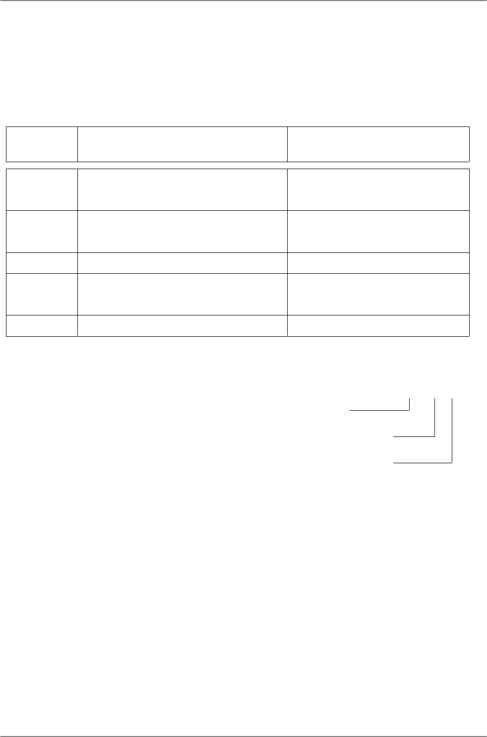
•SET-RAY2-EXT35
• Cable bushing lengthening, PG21, 35 mm
• O-ring
•SET-RAY2-EXT-F50
•Cable bushing lengthening, PG21, Flexi, 50cm
• orig. part no: LPA6-23N-0.5m, RKG-23P21N,
RKF-23P21N, 2xORC-23, flat ring FSN-P21
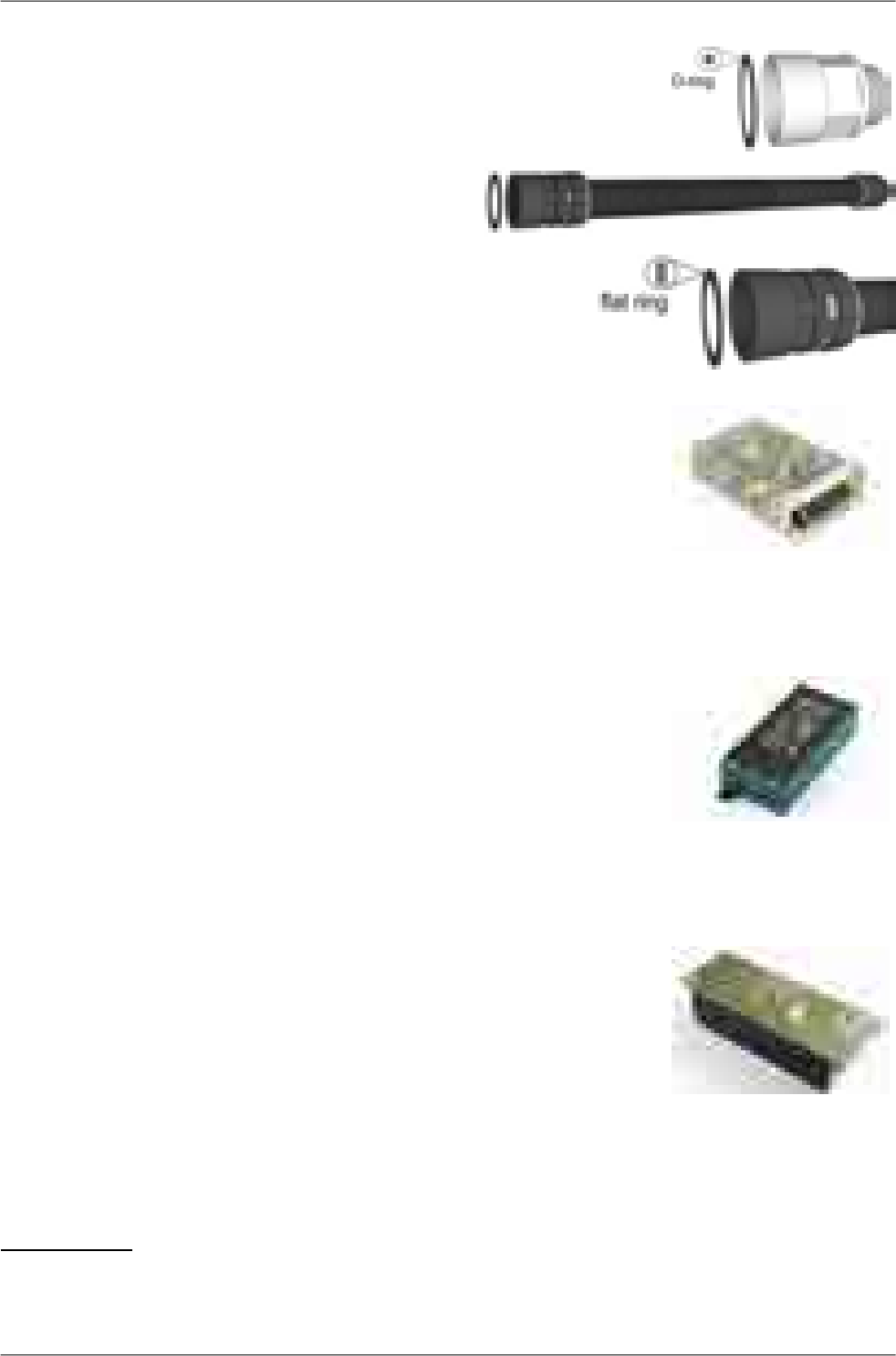
Power supply DC
•PWS-AC/DC-AD-55B
• orig. part no: AD-55B
• FOD unit power supply 50 W, 24 V, UPS Function, MeanWell
• Datasheet3
Power supply PoE
•PWR-POE36U-1AT
• orig. part no: POE36U-1AT
• FOD unit power supplies – 30 W PoE adapters, 1x Eth
• Input 100 to 240 VAC, Output 56 V / 33.6 W, Phihong
• Datasheet AC4
•PWR-POE36D-1AT
• orig. part no: POE36D-1AT
• Input 36 to 72 VDC / 1.2 A, Output 56 V / 33.6 W, Phihong
• Datasheet DC5
Power supply holder
•HOL-POE-PHI-1A
• 1x Eth PoE power supply, DIN rail mountable
3http://www.racom.eu/download/hw/ray/free/eng/07_prislusenstvi/PWS-AC-DC-AD-55B.pdf
4http://www.racom.eu/download/hw/ray/free/eng/07_prislusenstvi/PWR-POE36U-1AT.pdf
5http://www.racom.eu/download/hw/ray/free/eng/07_prislusenstvi/PWR-POE36D-1AT.pdf
31© RACOM s.r.o. – RAy2 Microwave Link
Accessories
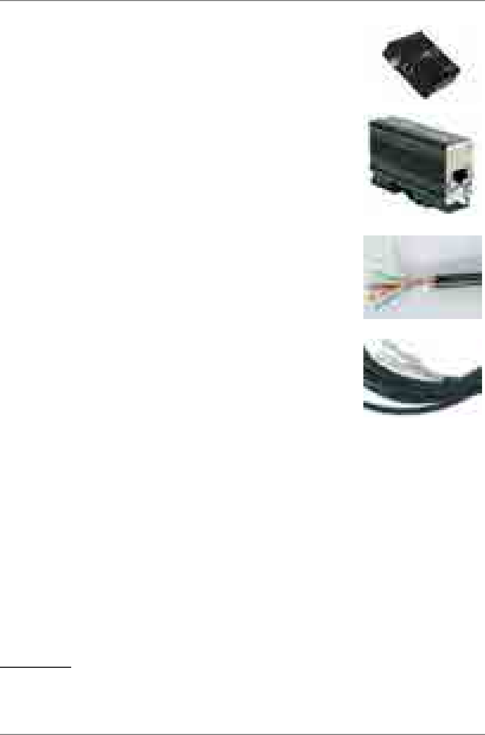
Surge protection
•OTH-DL-1GRJ45
• orig. part no: DL-1GRJ45
• Protection from the voltage spikes
• Datasheet6
•OTH-DL-CAT.6-60V
• orig. part no: DL-Cat. 6-60 V
• Datasheet7
CAT5e cable
•CAB-CAT5E-FTP-TLD
• orig. part no: PLU030078
• Cat.5e cable for connecting FOD units to the network, TELDOR
• Datasheet8
CAT7 cable
•CAB-S/FTP 4x
• orig. part no: S / FTP 4x (2x23AWG) Cat.7 + 2x (2×24 AWG)
• Cat.7 cable for connecting FOD units to the network,
PEWTRONIC Ltd.
• Datasheet9
6http://www.racom.eu/download/hw/ray/free/eng/07_prislusenstvi/OTH-DL-1GRJ45.pdf
7http://www.racom.eu/download/hw/ray/free/eng/07_prislusenstvi/OTH-DL-CAT-6-60V.pdf
8http://www.racom.eu/download/hw/ray/free/eng/07_prislusenstvi/CAB-CAT5E-FTP-TLD.pdf
9http://www.racom.eu/download/hw/ray/free/eng/07_prislusenstvi/CAB-SFTP-4x.pdf
RAy2 Microwave Link – © RACOM s.r.o.32
Accessories
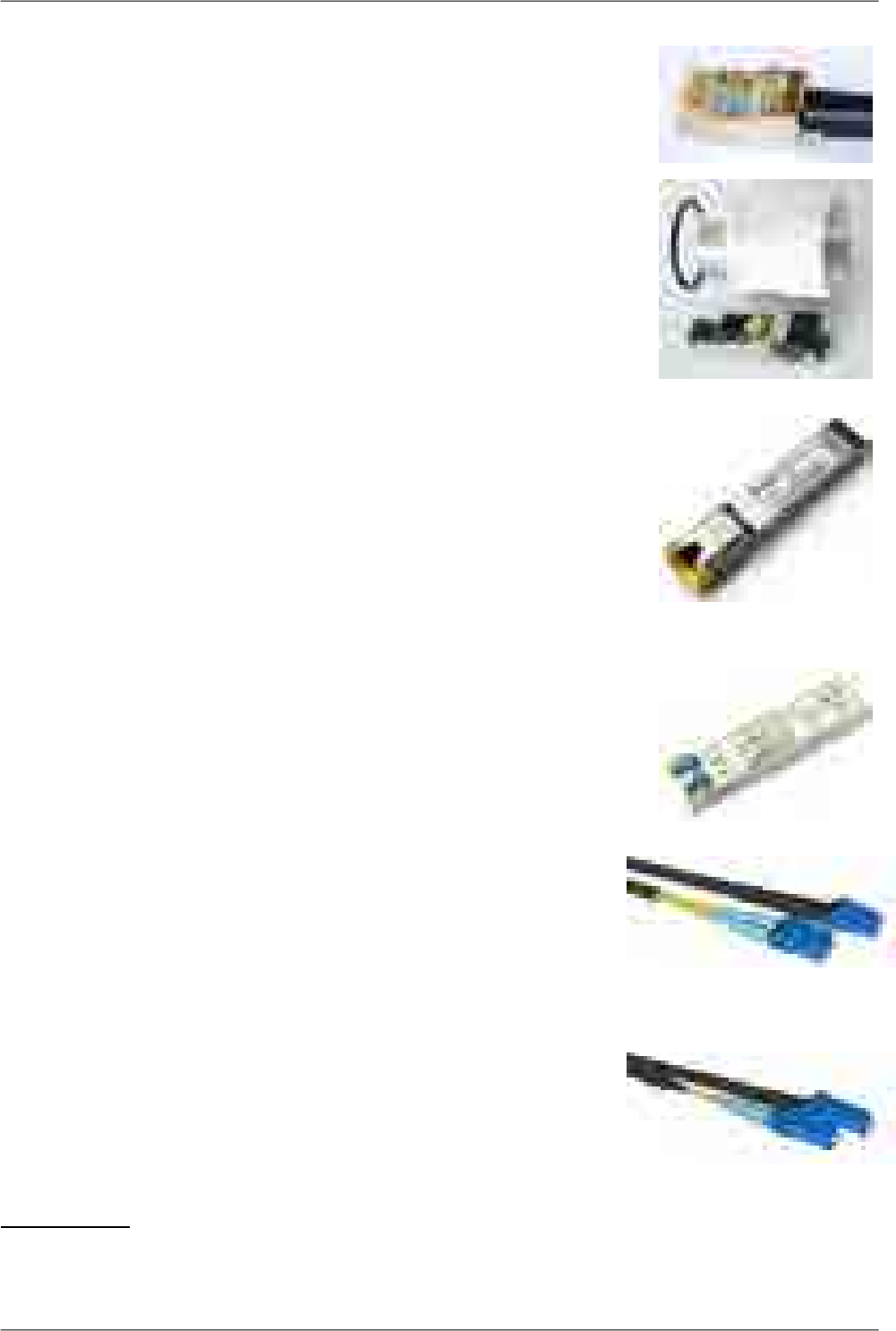
CAT6 connector
•CON-RJ45-UBNT-CAT6
• orig. part no: TC-CON connector STP RJ45
STP RJ45 /Cat6 / 8p8c / wire/ gold plated/ AWG24, UBNT
•SET-RAY2-TLG-EXT35
• orig. part no: Telegärtner MFP8 Cat.6A AWG 22-27
Connector RJ45, Cat6A, AWG 24-22, Telegärtner
+ Racom SET-RAY2-EXT35
•Set RJ45 connector (Telegärtner) and cable bushing lengthening
(35mm). Suitable for AWG24-22 (Cat5e, Cat6A, Cat7) cables.
• Datasheet10
SFP module RJ45
•SFP-RJ45-AVAGO
• orig. part no: ABCU-5730ARZ
SFP module, RJ45 interface, -40°C to +85°C , Avago
• Datasheet11
SFP module optical
•SFP-DLC-APAC
• orig. part no: LS38-C3S-TI-N-DD
SFP module, 2-fibres, LC, 10km, -40°C to +85°C, APAC Opto
• Datasheet12
Fibre cable - outdoor patchcord / outdoor pigtail
•CAB-FIB-2F-DLC/DLC-OFA-5m
• orig. part no: DLCRAC2Fyyy
patchcord, 2-fibres, single mode, LC-connector — LC-connector,
yyy meters, OFA
•CAB-FIB-1F-LC/LC-OFA-5m
• orig. part no: LCRAC1Fyyy
patchcord, 1-fibre, single mode, LC-connector — LC-connector,
yyy meters, OFA
10 http://www.racom.cz/download/hw/ray/free/eng/07_prislusenstvi/SET-RAY2-TLG-EXT35.pdf
11 http://www.racom.cz/download/hw/ray/free/eng/07_prislusenstvi/SFP-RJ45-AVAGO.pdf
12 http://www.racom.eu/download/hw/ray/free/eng/07_prislusenstvi/SFP-DLC-APAC.pdf
33© RACOM s.r.o. – RAy2 Microwave Link
Accessories

•CAB-FIB-2F-DLC/x-OFA-5m
• orig. part no: DLC0RAC2Fyyy
pigtail, 2-fibres, single mode, LC-connector — loose end,
yyy meters, OFA
•CAB-FIB-OFA-1F-LC/x-OFA-5m
• orig. part no: LC0RAC1Fyyy
pigtail, 1-fibre, single mode, LC-connector — loose end,
yyy meters, OFA
• Datasheet13
Fibre & DC outdoor cable
•CAB-HYB-2F-DLC/DLC-OFA-030m (example for 30m long cable)
• orig. part no: DLCHRAC2Fyyy Phoenix Microwave Hybrid Cable LSOH, yyy meters, OFA
DC: 2x1.5mm2; fibre: patchcord, 2-fibres, single mode, LC-connector — LC-connector
• Datasheet14
DC cable
•CAB-DC-2x1.5
• orig. part no: V05SS-F 2Dx1.50
silicone rubber, 2x1.5 mm², -40 to +60°C, ProPS
• Datasheet15
DC surge protection
•OTH-DP-024
• orig. part no: DC 24V
LPZ1-LPZ2, IP20, -40/+85°C , Saltek
• Datasheet16
13 http://www.racom.eu/download/hw/ray/free/eng/07_prislusenstvi/CAB-FIB-OFA.pdf
14 http://www.racom.cz/download/hw/ray/free/eng/07_prislusenstvi/CAB-HYB-OFA.pdf
15 https://webservice-new.racom.eu/main/eshop.detail?i=193
16 http://www.racom.eu/download/hw/ray/free/eng/07_prislusenstvi/OTH-DP-024.pdf
RAy2 Microwave Link – © RACOM s.r.o.34
Accessories

RAy grounding kit
•KIT-GROUDING-1/4"
• Grounding kit for Cat.7 S/FTP 4x(2x23 AWG) cable. Pewtronic.
• Detail see Grounding.
• Datasheet17
•KIT-GROUDING-RAY
• RAy grounding set for grounding RAy equipment to the mast.
Contains a ZSA16 grounding terminal, grounding tape and a
cable with grounding lugs.
• Detail see Grounding.
• Datasheet18
Access adapters
•OTH-W1-WIFI
• Wifi adapter for service access to the web interface via USB
connector. RAy2 provides a built-in DHCP server with up to 6
leases. To access the RAy2 always use the fixed IP
169.254.169.168 (Lower Unit) or 169.254.170.168 (Upper Unit).
•SET-X5-ETH/USB
•Ethernet adapter for service access to the web interface via USB
connector. RAy2 provides a built-in DHCP server with up to 6
leases. To access the RAy2 always use the fixed IP
169.254.169.168 (Lower Unit) or 169.254.170.168 (Upper Unit).
Extended descriptions
See www.racom.eu, Microwave link, Accessories19
E-shop
Accessories easiest to order here:
E-shop RACOM20
Use there a search engine Ctrl+F and RACOM-PART-NUMBER of the searched item.
17 http://www.racom.eu/download/hw/ray/free/eng/07_prislusenstvi/KIT-GROUDING-RAY.pdf
18 http://www.racom.eu/download/hw/ray/free/eng/07_prislusenstvi/ZSA16-en.pdf
19 http://www.racom.eu/eng/products/microwave-link.html#accessories
20 https://webservice-new.racom.eu/main/eshop.list?a=1&t=10
35© RACOM s.r.o. – RAy2 Microwave Link
Accessories
5. Step-by-step Guide
The following chapters will guide you step by step through preparation, installation and activation of
the RAy2 link:
• Pre-installation check out
•Installation (Chapter 6, Installation)
•Advanced configuration (Chapter 7, Configuration)
•Troubleshooting (Chapter 9, Troubleshooting)
Pre-installation Checklist
Familiarise yourself with the controls and prepare your configuration ahead of the installation of the
link on the mast tube.
Both units (without antennas) can lie on a desk with flanges running parallel and facing up at an angle;
on a non-metal desk they can also face downward. In the case of units RAy2-17 and RAy2-24 turn the
unit holders so that they are roughly perpendicular to each other. In the case of units operating in licensed
bands (RAy2-10, RAy2-11), turn unit holders so that they are roughly parallel to each other. Use an
ethernet cable to connect each of the units to a PoE source and connect a PC to one of them for con-
figuration.
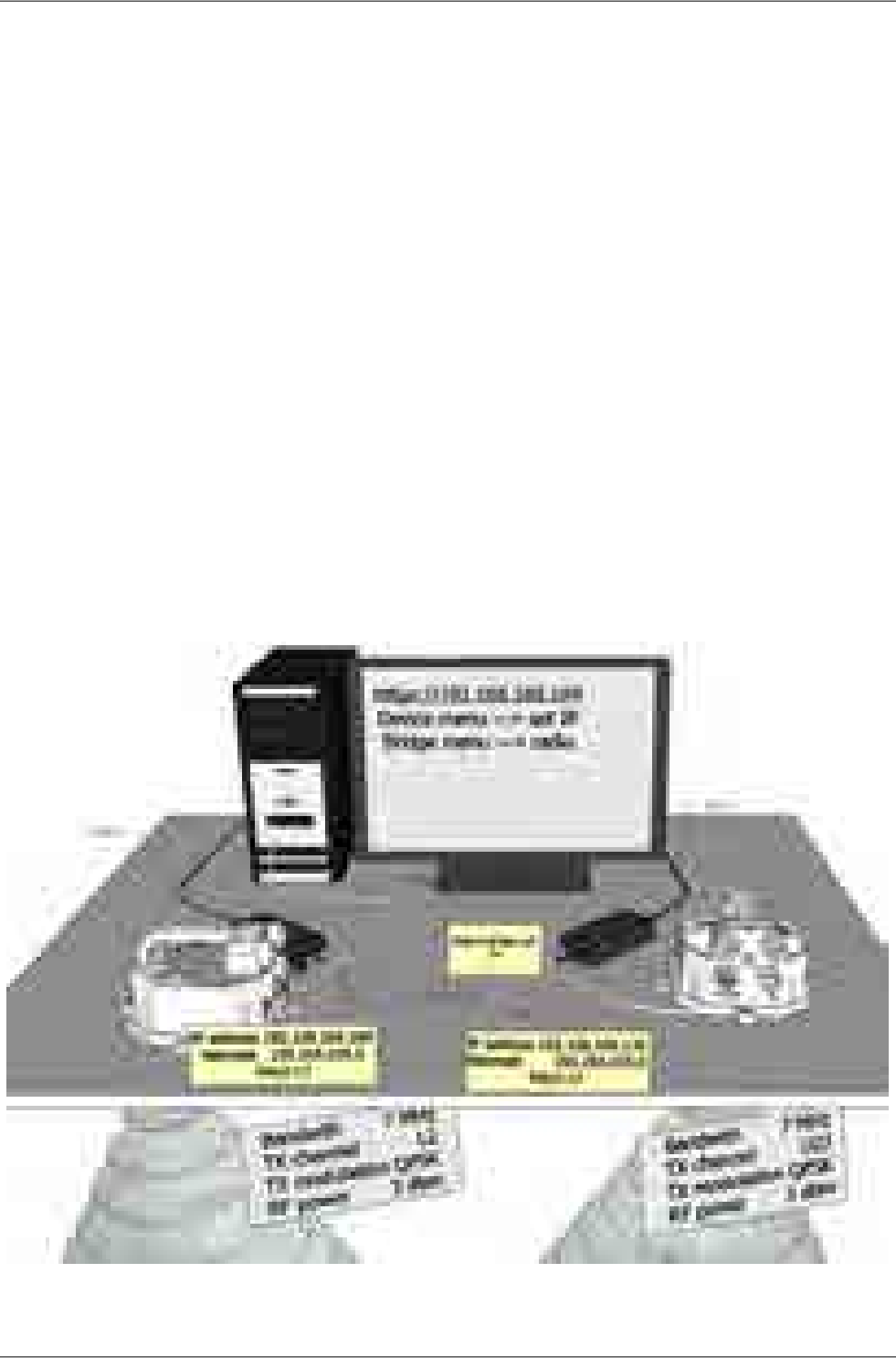
Take the following steps to establish a connection between the PC and RAy2 and perform a basic
setup.
Fig. 5.1: Link Configuration (RAy2-17, perpendicular holders)
RAy2 Microwave Link – © RACOM s.r.o.36
Step-by-step Guide

Warning
During operation, never bring the waveguides of the stations close to each other. There is
a risk of damaging sensitive input circuits.
5.1. Service access
The RAy2 link is supplied with a default configuration of access parameters:
Unit L has the service IP address 192.168.169.169 and mask 255.255.255.0,
Unit U has the service IP address 192.168.169.170 and mask 255.255.255.0,
access is allowed over HTTP, HTTPS or SSH,
the username is admin and the password is also admin.
On your PC setup an IP address that is within the mask, e.g. 192.168.169.180.
Then open the https configuration interface, e.g.
https://192.168.169.169
Other access options are described in the chapter Configuration - Link settings - Service access of this
manual.
When connection has been established, use the Service access menu to customise access parameters.
Default IP addresses should be replaced with well-chosen operating addresses. Leaving default ad-
dresses in place can lead to network problems later.
The menu contains parameters for the entire link, both for the Local and remote Peer units. If a connec-
tion has been established, both sets of parameters have been set. While working with an isolated unit,
only Local parameters are functional for the currently connected unit.
Note
If the link is OK and there are no parameters shown of the station Peer, it is necessary to
click on Refresh.
Follows the description of basic settings. After entering values on the screen always save the content
by clicking on Apply.
Note
If there is any problem with https certificate after completing the firmware upgrade, please
see the Annex Https certificate for further steps.
37© RACOM s.r.o. – RAy2 Microwave Link
Step-by-step Guide
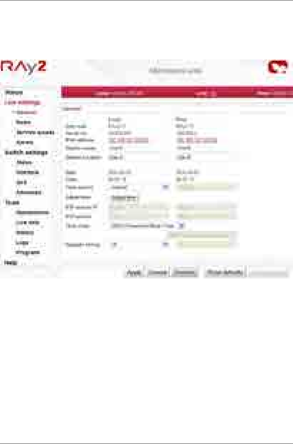
5.1.1. Menu Link settings - General
• Station name – station can be assigned with a name, e.g. the place of installation.
• Station location – for easier inclusion the network hierarchy, it is possible to enter the station’s loc-
ation
Fig. 5.2: Configuration Menu Link settings - General
RAy2 Microwave Link – © RACOM s.r.o.38
Step-by-step Guide
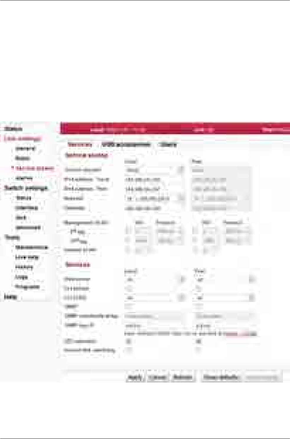
5.1.2. Menu Link - Service access - Services
•IPv4 address – enter a valid IP address to access the drive. The default IP address has to be replaced
with a valid address. Keeping the default address will probably lead to future problems in the network.
• Netmask – enter the network mask.
• Gateway – if necessary, enter a gateway, otherwise leave blank
• Enable access protocols that you are going to need. For security reasons, do not enable more than
is necessary.
• HTTP(S) – allow access to the web interface.
• Telnet – enabling access to the CLI interface using telnet protocol.
• SSH – enabling access to the CLI interface using SSH protocol.
• Management VLAN – Enabling 802.1Q VLAN tag for separation of user and service operations.
• Management VLAN id – Defining 802.1Q VLAN tag for service operations.
Fig. 5.3: Configuration menu Link settings – Service access – Services
39© RACOM s.r.o. – RAy2 Microwave Link
Step-by-step Guide

5.1.3. Menu Link - Service access - Users
•Edit - enter the menu.
•New password – choose a password and enter it.
•Confirm password – enter the password again to confirm.
Fig. 5.4: Configuration menu Link settings – Service access – Services
5.1.4. Menu Maintenance - Feature keys
The firmware of the microwave link is capable of controlling the maximum user data speed. The default
user speed without the feature key is the minimum for the respective hardware unit. The feature key
to assign the maximum user data speed, should be installed prior to physical installation. For further
details see the section called “Feature keys”.
5.2. Basic link configuration
Default radio parameters depend on the specific type of link and the specific channel allocation table.
Channels are typically set in the lower part of the band, the smallest bandwidth, QPSK modulation,
and low power. Both units in the pair should be capable of immediate communication. If it is possible to
work with these radio parameters at the installation location, the link can be activated. On an operating
link the required operating parameters can then be set up.
If a change in the parameters is necessary, it is done in the menu Link settings – Radio and saved by
clicking Apply. This applies when working on both units simultaneously if they are connected, otherwise
each unit is configured individually. When configuring units individually, pay attention to correct settings
of duplex pair for channels TX and RX. For example, if one station has TX channel L1, then the second
station must also have the channel RX L1.
5.3. Link test
Verify the functionality of the radio link:
•Switch in screen Status - Brief.
•Status Bar displays Link: Ok.
RAy2 Microwave Link – © RACOM s.r.o.40
Step-by-step Guide

If the alarm message appears at Local or Peer, this doesn’t necessarily mean there is a problem.
The message indicates that the limit at any of the monitored parameters has been exceeded. Es-
sential is the Link: Ok message on the status bar.
•The Status screen contains values for both Local and Peer units. N/A next to Peer indicates that
the data from the Peer unit has not been transferred. If Link is Ok, simply click Refresh at the bottom
of the screen and Peer data will be updated.
•Menu Status – Detailed – Radio indicates link RSS and SNR values, in case of ACM also the selected
modulation and Netbitrate. If the ATPC function is enabled (menu Link settings – Radio) it also in-
dicates instantaneous / max. allowed power and for SNR and RSS values it indicates immediate /
target value size.
•Menu Tools – Live data – Bar indicators displays current size of RSS, SNR and BER.
•Menu Tools – Ping allows you to send a ping test to the selected IP address.
Try out the possibility of modulation:
•Modulation ACM. In menu Link settings – Radio enable ACM. Set the TX modulation parameter to
the required maximum value. In menu Status – Brief – Radio you can monitor (Refresh or Start)
changes in used modulation based on the instantaneous SNR signal quality. The status and quality
of modulation is demonstrated well in menu Tools – Live data – RX constellation diagram, hit Refresh.
•To set a fixed modulation go to Link settings - Radio, switch off ACM and set the TX modulation to
a value from the range of QPSK through 256-QAM based on the results of the previous test. If you
choose modulation higher than allowed by SNR, the connection will be lost. Status Link will lose its
Ok value. Both units will need to be moved closer to resume the link. If this is not possible, use the
ethernet to access each unit individually and set the basic modulation QPSK. You can monitor the
quality of the received signal under Tools – Live data – RX constellation diagram.
Verify the functionality of the entire link:
• If possible, connect user devices to both RAy2 units over PoE and test mutual communication.
• Another way of testing this is to connect a PC to the other unit and send a ping from one PC to the
other.
• The minimum variant of this test is to use an ethernet cable connection from the PC connected to
the local RAy2 to the PC connected to the remote RAy2 and test communication between both
units over ethernet. This will verify ethernet functionality.
Prepare installation configuration:
•Bandwidth e.g. 3.5 MHz. To get the highest possible receiver sensitivity, set the bandwidth as narrow
as possible according to specific frequency band.
• TX channel: Use your allocated channel. If you don't have allocated channel yet, use for example
channel L1.
• RX channel will setup automatically when channel lock activates.
• Set TX modulation QPSK to get the highest possible sensitivity.
• Set RF power according to selected antenna and according to individual frequency licence. Set the
output power as high as possible.
• Set a new users access passwords.
• Record the access parameters from the Service access menu, especially the IP addresses.
• Restart by interrupting the power supply to verify that the parameters are stored correctly and the
link works.
After this preparation phase you can continue to install your devices in a working environment.
41© RACOM s.r.o. – RAy2 Microwave Link
Step-by-step Guide
6. Installation
6.1. Line of sight test
Before you install the device to a mast tube, verify visually that the view in the direction of the remote
unit is unobstructed.
Line of sight considerations:
• Free Fresnel zones. Signal needs space wider than the diameter of the antenna.
• Trees at the lower end of the Fresnel zone. They will be taller in a few years.
• Possible building development.
•Objects in the close proximity of the antenna such as edges of other antennas, their mounting racks,
edges of the roof.
6.2. Antenna mounting
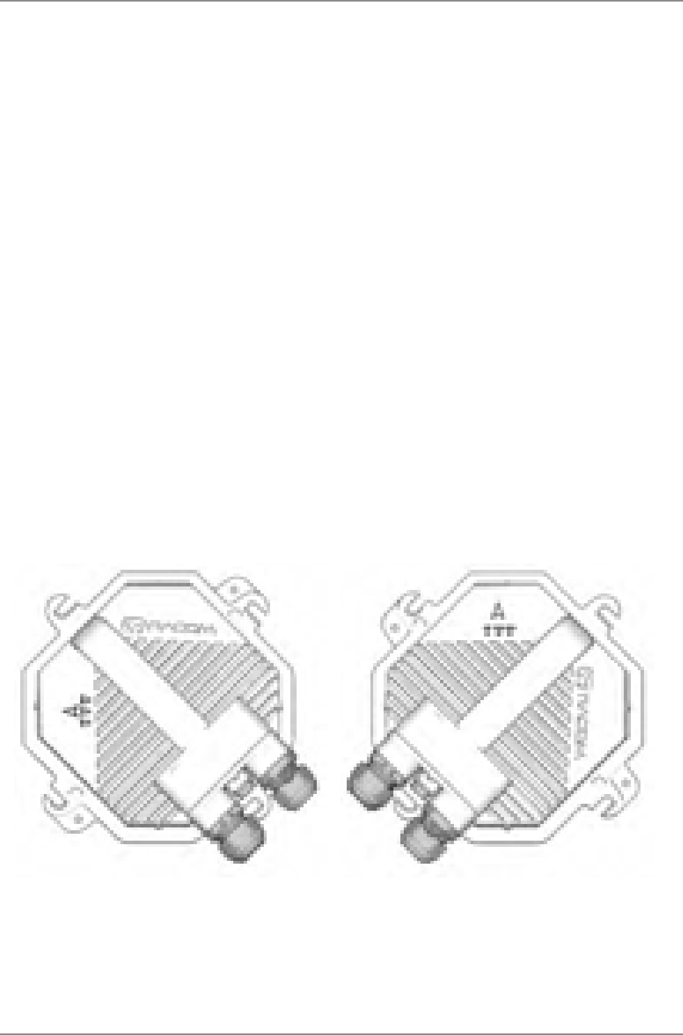
6.2.1. Mounting methods
• Mounting on the mast tube can be achieved by:
○ right-side mounting or
○ left-side mounting
• Mounting the FOD unit for antenna polarization can be achieved using:
○ horizontal RX polarization mounting or
○ vertical RX polarization mounting
In both cases mount the unit with the connectors facing downwards at an angle.
Fig. 6.1: Horizontal RX polarization
– see the arrow sign
Fig. 6.2: Vertical RX polarization
– see the arrow sign
RAy2 Microwave Link – © RACOM s.r.o.42
Installation
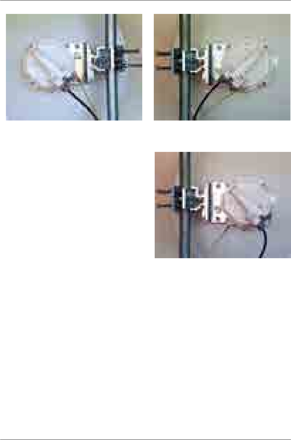
Fig. 6.3: Left-side mounting
– horizontal RX polarization
Fig. 6.4: Right-side mounting
– vertical RX polarization
Fig. 6.5: Right-side mounting – horizontal RX polarization
43© RACOM s.r.o. – RAy2 Microwave Link
Installation
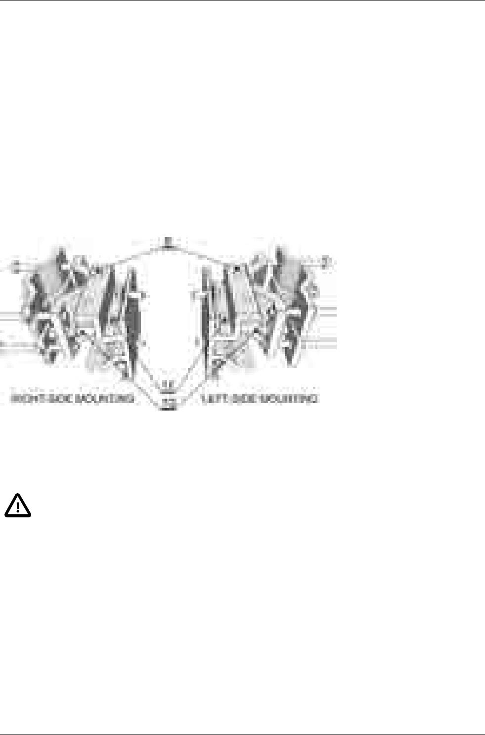
Changing the mounting method
An antenna bracket is supplied as standard partly assembled, and ready for right-side mounting.
On changing the Jirous antenna bracket for left-side mounting the adjustment bolt (part No. 11) and
swivel bolt (part No. 6) need to be unscrewed, then shift the bracket body (part No.5) to the other side
of clamp plate (part No. 4), (do not turn upside down) and then insert bolt (part No. 6) into the second
hole on the mounting plate holder and through the same hole on the clamp plate and secure in place
with the nuts. The adjustment bolt (item No. 11) and nuts are switched to the other side of the clamp
plate (part No. 4). It is also necessary to switch the hanging bolt (part No. 7) on the antenna mounting
plate to the second hole so that after switching sides with the antenna it is on the top again.
In the case of the antenna when changing the method of mounting from right-side to left-side it is only
necessary to rotate the plastic cover of the antenna. This is not only important from an aesthetic point
of view, so that the RACOM logo is not upside down, but also because there is a discharge channel
on the lower edge of the dish (except for ø380 mm dishes).
Fig. 6.6: Changing the mounting method
When changing the polarization from horizontal to vertical only the FOD unit needs to be turned through
90° around the central antenna pin by unscrewing the four bolts on the dish using a No. 6 Allen key.
Important
The RAy2-17 and RAy2-24 links are equipped with a polarization duplexer and work in both
polarizations simultaneously, see Cross polarization. One side of the link must therefore
be installed in vertical polarization and the other in the horizontal polarization.
RAy2 Microwave Link – © RACOM s.r.o.44
Installation
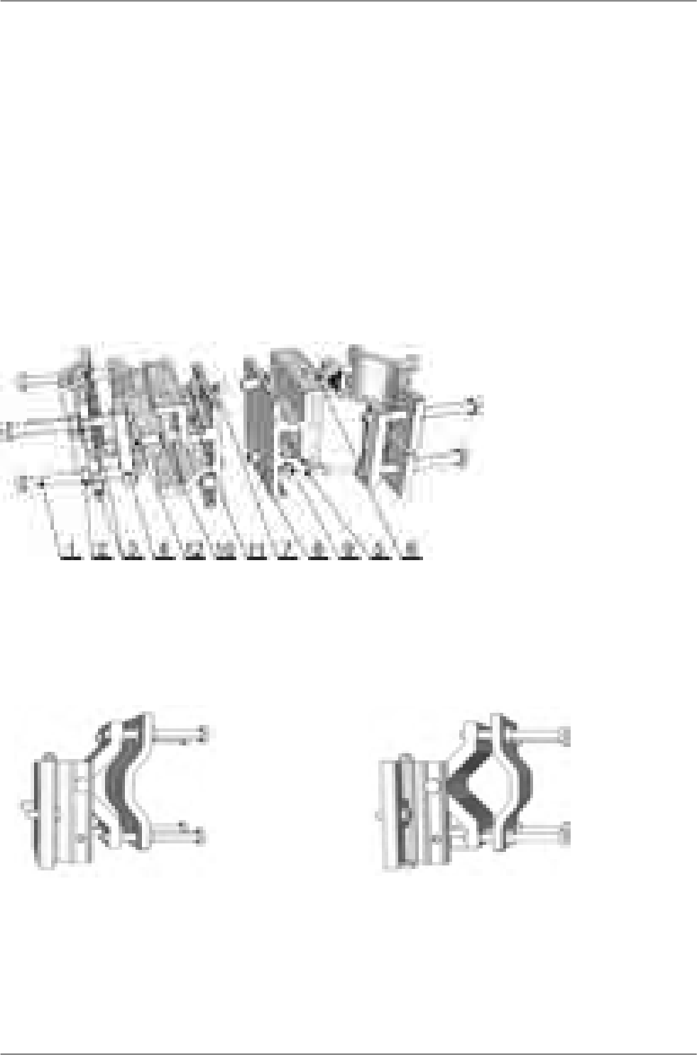
6.2.2. Mounting the FOD unit on the antenna
RAy2 microwave bridge equipment is generally supplied as several component parts packaged separ-
ately in a box.
• Two parabolic antennas with assembled mounting plates. There are also 4 screws in a small plastic
bag in the box.
• Two brackets for mounting the antenna to the mast.
• Two FOD stations, each separate in a box, in a single package.
• Other accessories based on the order placed (for more detailed information see chapter Chapter 4,
Accessories)
A No. 17 spanner and a No. 6 Allen key are required for mounting the mechanical parts of the antenna.
Spanner No. 17 serves for precisely setting the direction of the antenna. Both spanner and key can be
found in the RAy Tool set for installing RAy2 microwave bridges.
It is advisable to lightly lubricate the retaining screws eg. by the supplied grease.
Fig. 6.7: Close up image of the mounted bracket showing numbered parts
a. Prepare the antenna bracket based on the diameter of the mast tube. For smaller diameters face
the bent part of the saddle plate (part No. 3) inwards. For larger diameters it should face outwards.
Screw the bolts (part No. 1) into the clamp plate (part No. 4) so that they protrude approx. 1 cm
through the clamp plate. Clamp the saddle plate to the mast by tightening the nuts (part No. 2) on
the bolts.
Fig. 6.8: Position of the saddle plate for
ø 40–80 mm
Fig. 6.9: Position of the saddle plate for
ø 65–115 mm
45© RACOM s.r.o. – RAy2 Microwave Link
Installation
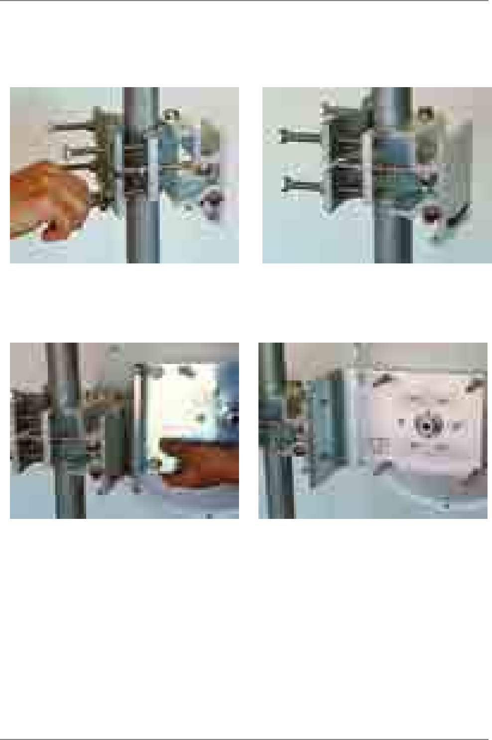
b. Slide the antenna bracket onto the mast tube and clamp to the mast by tightening the nuts.
Recommendation: Keep the gap between the two saddle plates (part No. 3) as wide as possible,
so the horizontal angle adjustement screw can fit in this gap. The range of horizontal adjustement
is consequently wider. This has a bigger effect when the mast diameter is smaller.
Fig. 6.10: Attaching the bracket to the mast tube Fig. 6.11: Bracket on the mast tube
c. Screw the hanging bolt (part No. 7) into the upper hole of the mounting plate so that the antenna
can be hung on the mounting plate holder. Hang the antenna on it and tighten the lower bolt. (part
No. 8)
Fig. 6.12: Hanging the bolt on the holder Fig. 6.13: Correct position of the mounting plate
RAy2 Microwave Link – © RACOM s.r.o.46
Installation
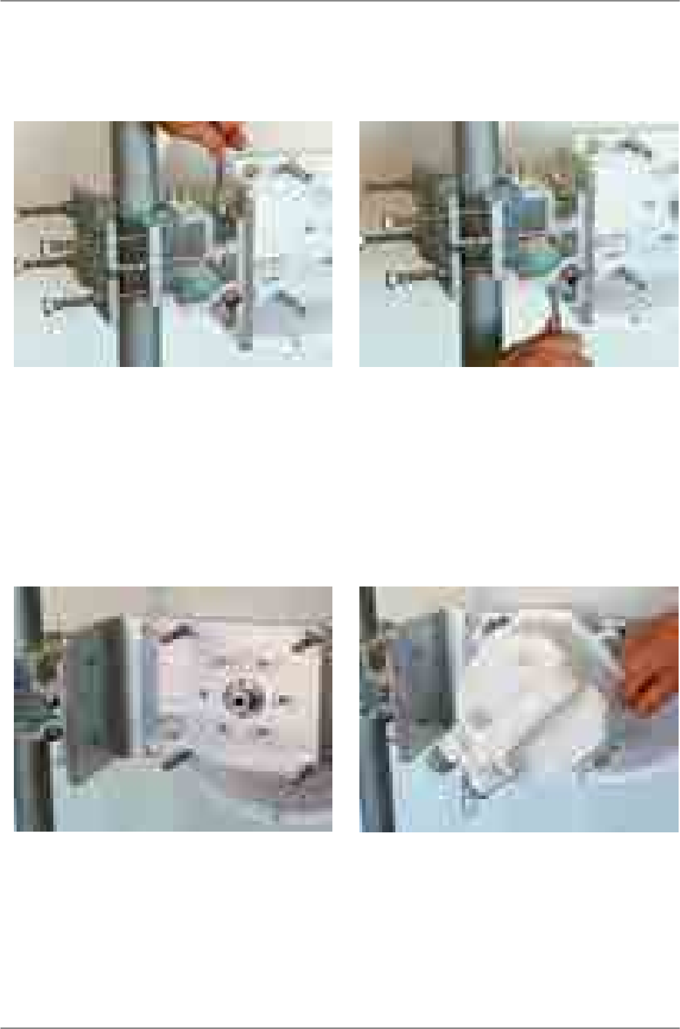
d. Tighten both bolts to the plate before continuing with installation to prevent any unnecessary
movements of the equipment. Before precisely adjusting the vertical direction of the antenna upon
completing installation it will be necessary to unscrew them again as the lower bolt (part No. 8)
passes through the adjustment block and the upper one (part No. 7) serves as the axis of rotation.
Fig. 6.14: Tightening the upper bolt to
the mounting plate
Fig. 6.15: Tightening the lower bolt to
the mounting plate
e. Before installing the FOD unit on the antenna first unscrew the 4 bolts on the back of the antenna
enough so that the unit can be slid on to them. Then check whether the "O" ring is correctly fitted
on the antenna pin, and make sure it is not damaged and has been lubricated with grease – see
Section 6.2.3, “Lubrication and preservation of the antenna pivot”. Then remove the protective
plastic cover from the central pin of the antenna and fit the FOD unit to it carefully so as not to
damage the "O" ring. Secure it in place with the four bolts. Carefully ensure the correct polarization
of the antenna – see Section 6.2.1, “Mounting methods”. Finally tighten the bolts with a No. 6 Allen
key.
Fig. 6.16: Dish before installing the FOD unit Fig. 6.17: Tightening bolts on the FOD unit
47© RACOM s.r.o. – RAy2 Microwave Link
Installation
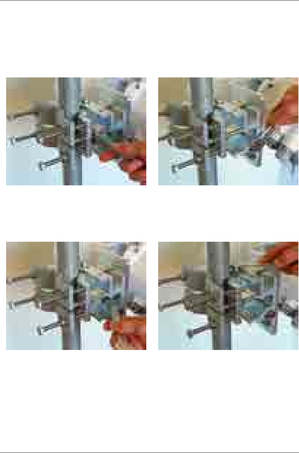
f. The precise horizontal direction the antenna is pointing in can be adjusted using the bolt with two
nuts (part No. 10 and 12). Once the direction has been set the antenna is fixed in place by tightening
the nuts against the bracket to prevent further movement of the antenna. The vertical direction the
antenna is pointing in can be adjusted by turning the fine adjustment bolt (part No. 9) by the
bracket mounting plate. After selecting the correct direction the position is secured by tightening
the bolt – see point d. (part No. 7 and 8). The correct position in both directions is found by monit-
oring RSS voltage, see Section 6.5.2, “Directing antennas”.
Fig. 6.18: Horizontal adjustment of the
antenna direction
Fig. 6.19: Vertical adjustment of the
antenna direction
g. After pointing the antenna in the right direction tighten the bolts on the bracket on the axes of rotation
(part No. 6 and 11). Then check again that all other bolts have been sufficiently tightened. We can
now proceed to connect the FOD unit to the user network.
Fig. 6.20: Tightening the axis at the fine
adjustment bolt
Fig. 6.21: Tightening the axis at the bracket
RAy2 Microwave Link – © RACOM s.r.o.48
Installation
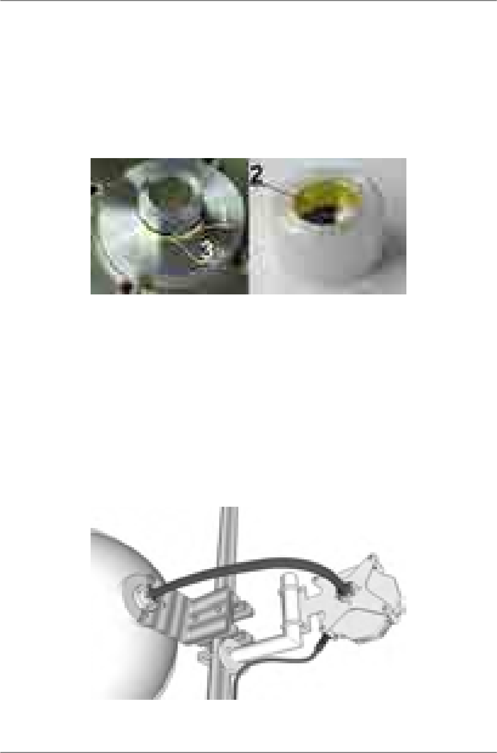
6.2.3. Lubrication and preservation of the antenna pivot
Before fitting the FOD unit bush onto the antenna pivot ensure that the "O" ring (part No. 1) is in the
correct position. It is also essential to prevent moisture getting in between these two parts. This moisture
could cause oxidation which would complicate disassembly of this mechanical coupling in the future.
For this reason we need to treat these surfaces with the grease which is supplied in the box marked
"SILIKONOVE MAZIVO". If you use a different grease for lubrication then it should be a Teflon or a
silicon grease.
Fig. 6.22: Grease points on the antenna pivot and FOD unit bush
Grease the internal area of the bush on the FOD unit (2) and the "O" ring (1) with a thin even layer that
allows the pin to slide easily into the bush without damaging the "O" ring. Grease the area beyond the
"O" ring on the antenna pin (3) with a thicker layer so that it fills the gap caused by the play between
the pin and the bush (max. 0.1 mm/ø) thus preventing moisture getting in. Installation should be carried
out according to the antenna installation description – see point f of this description.
The tub with grease is supplied with the RAy2 units.
6.2.4. Flexible waveguide
Any type of antenna may be connected to the RAy2 unit using a flexible waveguide. Flexible waveguide
mounting kit can be ordered as an accessory part.
Fig. 6.23: Flexible waveguide assembly
49© RACOM s.r.o. – RAy2 Microwave Link
Installation
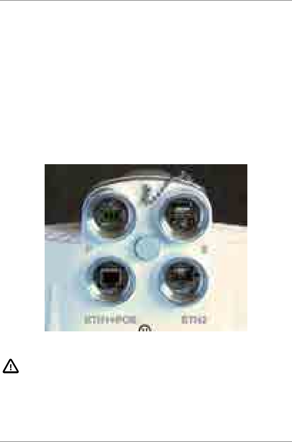
6.3. Connectors assembly
The FOD communication unit can be connected to the user network by metallic or fibre Ethernet cable.
The unit is equipped with those connectors:
■ ETH1+POE – Gigabit metallic Ethernet port. This port can power the unit with any Power over
Ethernet power source working according to IEEE 802.3at standard.
■ ETH2 – Slot for user exchangeable SFP module. A wide range of optical modules is available. Both
single or dual mode transceivers can be used. The SFP module with metallic RJ45 interface can
be used as well. Please see the Important notice.
The SFP status LED is located just next to the slot.
■ P – DC power connector.
HW button for service purposes.
■ S – USB service connector.
RSS voltage output connectors.
Fig. 6.24: FOD communication unit connectors
Important
Before connecting the FOD communication unit to the supply (to the user network) the FOD
unit must be grounded according to Section 6.4, “Grounding”.
RAy2 Microwave Link – © RACOM s.r.o.50
Installation
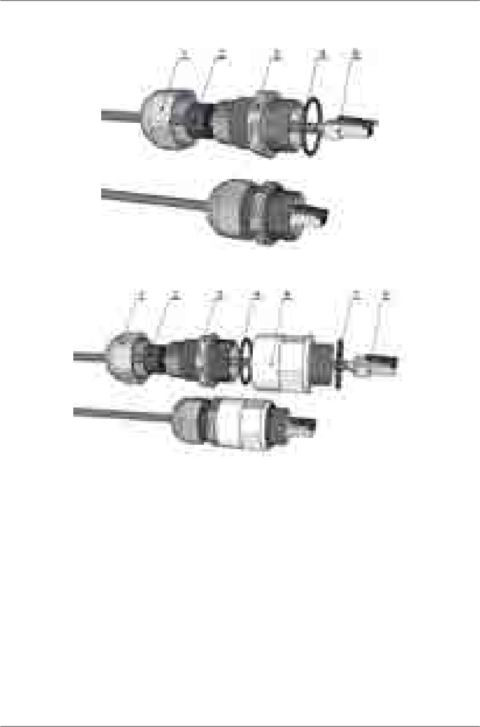
Assembly procedure:
Fig. 6.25: Bushing and connector assembly
Fig. 6.26: Bushing incl. lengthening and connector assembly
• Put on the cable: the nut No.1, rubber sealing No.2, bushing No.3 and O-ring No.4.
• Attach the appropriate connector No.5 to the cable.
• Plug the connector No.5 into the RAy2 unit.
• Screw the bushing No.3 with the sealing O-ring into the RAy2 unit.
• Move the rubber sealing No.2 along the cable to fit in the bushing. Screw the nut No.1 on bushing
No.3.
• (If you use extension ring No. 6 lubricate its thread with grease.)
Disassembly procedure:
• Release the nut No.1
• Remove the rubber sealing No.2
• Unscrew the bushing No.3 with O-ring No.4 (and extension No.6 with O-ring No.7).
• Remove the connector.
51© RACOM s.r.o. – RAy2 Microwave Link
Installation
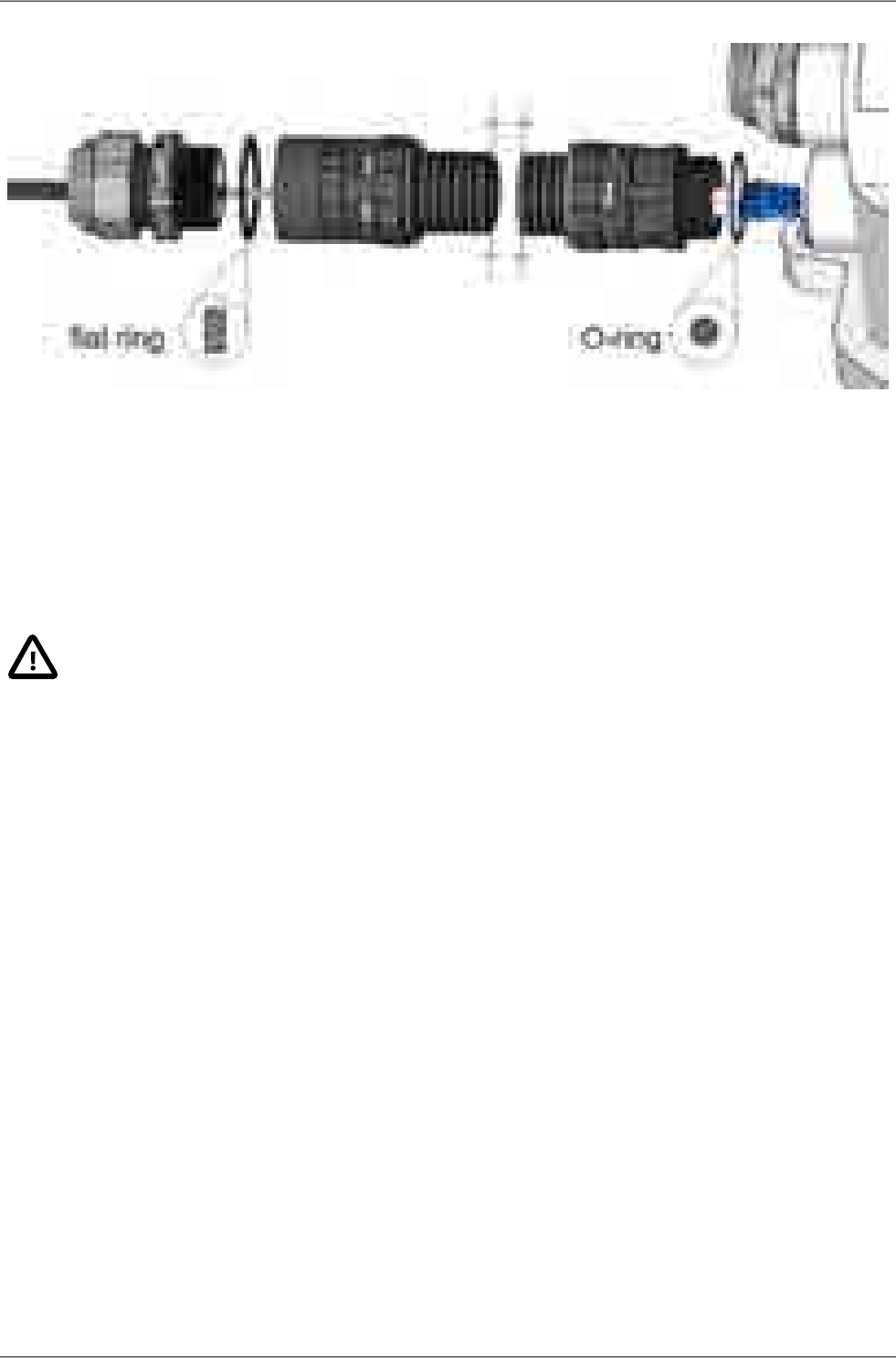
Fig. 6.27: Bushing including long lengthening
All necessary parts are delivered as an accessory SET-RAY2-CON-B. If the lengthening is needed
use the extension SET-RAY2-EXT35 containing the parts No.6 and No.7 or use the longer extension
SET-RAY2- EXT-F50.
The rubber sealing is delivered with three different internal diameters to fit different cable diameters.
The rubber is diagonally cut to enable sealing of cables with preinstalled connectors.
Important
All bushings and plugs (including the original plugs in the ports) must be fitted with O-
rings and carefully tightened. Failure to do so may result in moisture accessing the in-
ternal workings. In such a situation the functionality cannot be guaranteed.
•
• Before screwing extension ring (part No.6) into the RAy2 housing, lubricate its thread
with grease.
• When using other bushing or connector than the delivered there is a danger of bad seal
or damaging the connector. Interior space can be small.
6.4. Grounding
The lightning and overvoltage protection system example, designed in accordance with regulation CSN
EN 62305.
1. Where possible the antenna should be located in an LPZ 0B protection zone with the use of a
local or artificial air termination device for protection against direct lightning strikes.
2. When meeting conditions for ensuring electrical insulation (distance from the lightning conductor)
in accordance with article 6.3, it is not recommended to ground the load-bearing structure and
antenna to the external air termination network. Grounding should be attached to the protective
system of the internal LV wiring or grounded internal structures using a CYA 6 mm2bonding con-
ductor , see Fig. 6.28, “Grounding installation 1”
RAy2 Microwave Link – © RACOM s.r.o.52
Installation
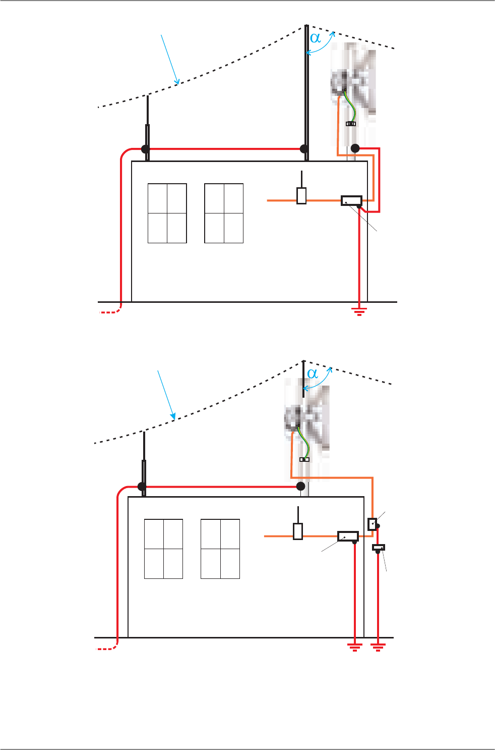
R
ETH
ETH
230 V~
PoE
LPZ 0A
LPZ 0B
LPZ 1
LIGHTNING
ARRESTER
Fig. 6.28: Grounding installation 1
ETH
ETH
230 V~
PoE
R
LPZ 0A
LPZ 0B
LPZ 1
GROUNDING KIT
LIGHTNING
ARRESTER
Bonding bar
Fig. 6.29: Grounding installation 2
53© RACOM s.r.o. – RAy2 Microwave Link
Installation

3. If it is not possible to set up conditions of electrical insulation in accordance with article 6.3 we re-
commend connecting the load-bearing structure at roof level to the external air termination network
via an 8mm diameter FeZn conductor and shielding the data cable before entry to the building
with a grounding kit and CYA 6 mm2conductor to the bonding bus, and if not already set up then
also to the external air termination network, see Fig. 6.29, “Grounding installation 2”
4. If there is not an external LPS on the building we recommend routing lightning current through an
8mm FeZn conductor to a common grounding system, or to a separate grounding electrode with
a ground resistance up to 10 Ω.
5. For limiting the overvoltage transferred over the data cable and into the building we recommend
fitting surge protection at the interface between zones LPZ 0 and LPZ 1 connected via a CYA 4
mm2conductor to the same grounding point as the antenna or the antenna mast.
6. We recommend protecting the PoE power supply from overvoltage on the LV side with suitable
class D surge protection.
The RAy2 unit is grounded to the flange at the fixing screws using an M8 screw. An insulated copper
cable with a minimum cross-section of 6 mm2terminated with a terminal lug is used as a protective
conductor. The conductor should have a green/yellow plastic cover along its whole length. For
grounding a RAy grounding kit can be ordered as an accessory (see Chapter 4, Accessories) containing
a grounding terminal ZSA16, 40 cm grounding strip 15 mm wide, and 100 cm of cable with grounding
lugs. For instructions on installing terminals see the datasheet RAy grounding kit1. A qualified person
must install the antenna.
Racom supplies surge protection for installation on Ethernet cables entering buildings. For more details
see Surge protection2.
Additional safety recommendations
• Only qualified personnel with authorisation to work at heights are entitled to install antennas on
masts, roofs and walls of buildings.
• Do not install the antenna in the vicinity of electrical wiring. The antenna and bracket should not
come into contact with electrical wiring at any time.
• The antenna and cables are electrical conductors. During installation electrostatic charges may
build up which may lead to injury. During installation or repair work to parts of the antenna lead,
bare metal parts must be temporarily grounded.
• The antenna and antenna cable must be grounded at all times. See Section 6.4, “Grounding”.
• Do not mount the antenna in windy or rainy conditions or during a storm, or if the area is covered
with snow or ice.
• Do not touch the antenna, antenna brackets or conductors during a storm.
1http://www.racom.eu/download/hw/ray/free/eng/07_prislusenstvi/ZSA16-en.pdf
2http://www.racom.eu/eng/products/microwave-link.html#accessories
RAy2 Microwave Link – © RACOM s.r.o.54
Installation

Fig. 6.30: Grounding kit for S/FTP 4+2 cable Fig. 6.31: Grounding kit detail
Fig. 6.32: Protective conductor at the FOD unit Fig. 6.33: Grounding the FOD unit
Fig. 6.34: Protective conductor at the mast
on a ZSA16 terminal
Fig. 6.35: RAy grounding kit
55© RACOM s.r.o. – RAy2 Microwave Link
Installation
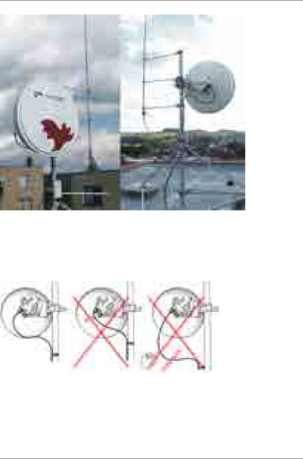
Fig. 6.36: Separated lightning conductor
Note - It is always better not to install the microwave unit directly under the lightning conductor holders.
There is lower probability of unit being polluted by birds.
It is necessary to install the Ethernet lead so that there is no excessive mechanical stress applied on
the connector bushing:
Fig. 6.37: Example of a correct lead installation.
RAy2 Microwave Link – © RACOM s.r.o.56
Installation

6.5. Start up
Connect a power supply to the installed FOD unit and connect the configuration PC. Use an internet
browser (such as Mozilla Firefox) to enter the configuration menu.
6.5.1. Noise on the site
This is particularly true for installation of links working in free bands, where the user has no secured
frequency.
Analyse the level of noise in the individual channels using the spectrum analyzer under Tools – Live
data – Frequency spectrum analyzer. If necessary adjust the choice of working channel on the basis
of the results.
While doing so respect the rule that in one location all units emit a signal in the Upper part of the range
and receive it in the Lower part of the range, or the other way round. A transmitter must not be installed
in the part of the spectrum where other units function as receivers.
6.5.2. Directing antennas
If it is possible, use a narrow channel, low modulation and high power for the first antenna directing
alignment. Working on both ends of the link simultaneously is favourable. Connect a voltmeter to the
connectors and observe RSS changes in 2 V DC range. A stronger signal corresponds to lower voltage.
Alternate units on both sides and slowly adjust the antenna vertically and horizontally to find the position
with the strongest reception. At the same time look for the main signal maximums. To differentiate
between the main and the side maximums refer to the Main and side lobes paragraph.
RSS measurement
For correctly setting the bridge and positioning it in the right direction it is advisable to connect a PC
and use the diagnostic capabilities of the RAy2 station. In uncomplicated cases it is enough to connect
a voltmeter via connectors and adjust to the lowest indicated voltage. Voltage is calibrated according
to signal strength. E.g.:
RSS -65 dBm corresponds to voltage 0.65 V,
RSS -80 dBm corresponds to voltage 0.80 V etc.
Fig. 6.38: RSS connectors
Fig. 6.39: RSS connectors
- connecting a voltmeter
57© RACOM s.r.o. – RAy2 Microwave Link
Installation
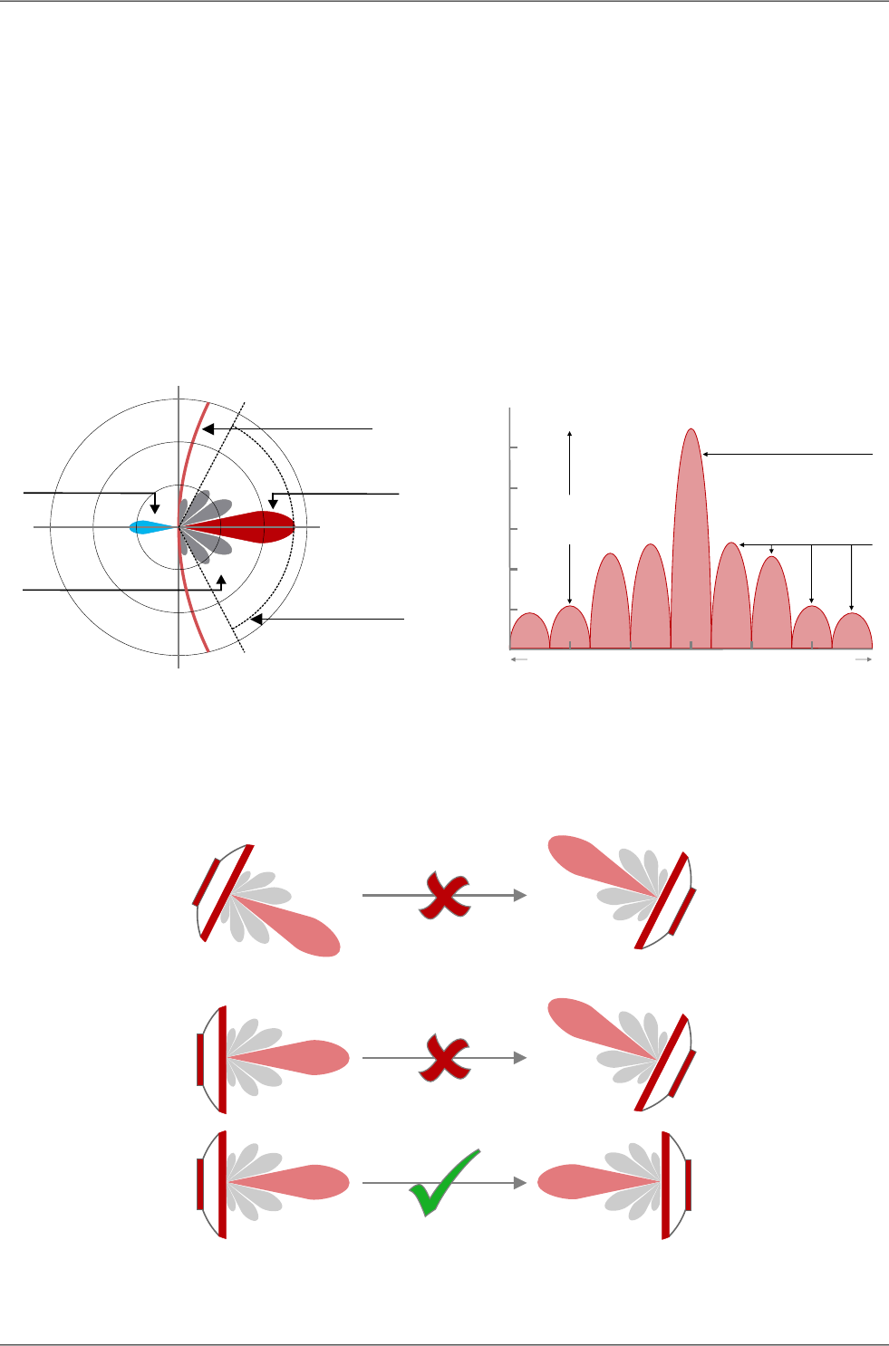
Main and side lobes
Directional antennas have a specific angle within which radio waves can be transmitted or received
(Angle of Tx/Rx).
The strongest signal is emitted in a forward direction; the main lobe is a graphical representation of its
direction of travel and strength.
However signals are also emitted and received from unwanted directions through side lobes. In receiving
antennas this is a highly significant factor contributing to the level of interference in a radio network
(See Fig. 6.40, “Antenna lobe diagram”).
Fig. 6.41, “Signal strength graph” provides an indication of comparative signal strength from different
beams emitted from a directional antenna.
Antenna
Angle of T / Rx x
Main lobe
Back lobe
Side lobes
0
90
-90
0
0
0
Fig. 6.40: Antenna lobe diagram
0-180
Angle (Degrees)
Directivity (dBi)
Main lobe
Side lobes
Side lobe
level
18030 60-60 -30
Fig. 6.41: Signal strength graph
Placing the antennas to the correct antenna alignment is very important to ensure the strongest signal
is received:
Fig. 6.42: Correct alignment diagram
RAy2 Microwave Link – © RACOM s.r.o.58
Installation
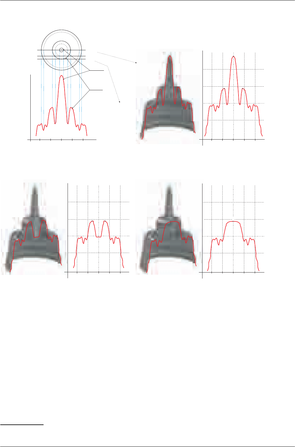
Examples
5
4
-40°
0
10
20
-10
G[dbi]
-20° 20° 40°0°
6
-40°
0
10
20
-10
G[dbi]
-20° 20° 40°0°
-40°
0
10
20
-10
G[dbi]
-20° 20° 40°0°
2
13
A–A
B–B C–C
CROSS-SECTION A – A
CROSS-SECTION C – C
-40°
0
10
20
G[dbi]
-20° 20°0°
MAIN
BEAM
SIDE
LOBE
A A
B B
C C
40°
2
13
6
45
Fig. 6.43: Radiation diagrams
Both antennas should be oriented towards each other using the peaks of the radiation diagram. Adjust
the antenna alternately in the horizontal and vertical axes and monitor the resulting signal strength.
Use the calculation of the expected RSS with the precision of several dBm as guidance. Side lobes
transmit a signal ca 20 dBm weaker, see the Microwave link Calculation3.
3http://www.racom.eu/eng/products/microwave-link.html#calculation
59© RACOM s.r.o. – RAy2 Microwave Link
Installation

Fig. 6.44: Radiation diagram – incorrect adjustment
The resulting RSS helps distinguish between
the states A-A and C-C which appear similar.
It also helps in situations where simple search
for a maximum doesn’t work as shown in the
illustration “incorrect adjustment”.
Real radiation diagrams are more complex,
especially in that they run differently in horizont-
al and vertical axes. The basic steps for determ-
ining the main radiation lobe however stay
valid. For example:
Fig. 6.45: 3D example of more complicated Radiation Pattern
RAy2 Microwave Link – © RACOM s.r.o.60
Installation

6.5.3. Link test
Basic parameters of the link are shown in the menu Status – Brief, its quality is characterized by RSS
and SNR. Values on Status screens can be refreshed manually by pressing the Refresh button or
in real time with a period of several seconds after activating the Start button. Press the Stop button to
terminate the periodic refresh of values.
The RSS, SNR and BER values can also be viewed on the screen Tools – Live data – Bar indicators.
After pressing the Start button, values will be refreshed with a period of one second.
After installation, it is good to reset the statistics using the Clear stats button in menu Status – Detailed.
This allows easier diagnostics of the link’s reliability over time.
6.5.4. Parameters setup
After both antennas have been aligned, setup operation parameters for the link. In the case of links
operating in the free band, setup the parameters based on survey results from the tool Tools – Live
data – Frequency analyser. In the case of links operating on a licensed band, setup the parameters
based on the assigned license:
• Bandwidth
• Channel Selection (TX / RX channel)
•Modulation (TX modulation) – ACM is recommended. When selecting fixed modulation it is necessary
to account for the fade margin. If fixed modulation is setup close to a possible maximum, then a
deterioration in RSS could endanger the link both for data transfer as well as service access.
• Transmit power (TX power), or ATPC
• Verify and record IP addresses
• Define access channels – https / telnet / ssh / ssh with password
• Check the users password settings.
Restart both units by interrupting their power supply and verify the status of the link. This verifies that
all parameters have been stored correctly in the memory.
Select Tools – Maintenance – Backup – Settings (Local & Peer) - Download and save the configuration
to backup file “cnf_backup.tgz”.
This completes the installation. Further configuration can be performed remotely.
61© RACOM s.r.o. – RAy2 Microwave Link
Installation

7. Configuration
7.1. Introduction
Controls
The following configuration buttons are used for configuration:
Apply and save parameters.Apply
Set parameters are overwritten with original values.Cancel
Reload all current values of the unit / both units.Refresh
Show values of individual parameters as they are stored in backup configuration (in
the buffer). To use any of these values, you must use the Apply button.
Show defaults
Clicking the button displays the values of individual parameters held in the backup
file (Backup – Settings – Open file upload). To use any of these values, you must use
Show backup
the Apply button. For loading the backup configuration see menu Tools – Maintenance
– Backup.
Activating automatic refresh fields marked by icon using the Start button with the
frequency cca 1 sec.
Start
Use the Stop button to stop automatic refresh of displayed information with 1sec
period. Date and time values are refreshed anyway.
Stop
Fig. 7.1: Info Refresh
Help
The microwave link configuration system is equipped with built in Help - see Help section. The Help is
accessible in two forms:
• Configuration parameter context help. The help text is displayed in the pop up window after clicking
the parameter name.
• The whole user interface help. The help text is displayed within the configuration screen after
clicking the Help menu.
Secure login
You can login into the configuration interface using either the insecure http protocol (default login
screen), or the secure https protocol. You should select the connection method on the login screen.
If the https protocol is used, it is not possible to tap the network communication and acquire the station’s
login information.
RAy2 Microwave Link – © RACOM s.r.o.62
Configuration

Fig. 7.2: Login
Rollback function
If you interrupt the connection on an operating link by entering inappropriate radio link parameters, the
original parameters will be restored after 1 minute. The connection is automatically restored.
7.2. Status bar
Fig. 7.3: Status bar 1
The Status bar is located on the upper part of the screen below the title bar. It consists of 3 fields:
•Local unit status (unit assigned to the IP address entered in the browser or CLI)
• Local to Peer Link status.
•Peer unit status.
Local and Peer field displays:
• Station name according to configuration.
• Actual time valid for respective unit.
• Warning or Alarm icon in case of warning or alarm.
Link field display:
• Status of the link between both sides of the microwave link.
• Warning icon when the link is not capable of user data transfer.
The Link status can be one of the following values:
Unit start up. The initialization is not yet finished.UNKNOWN
Unit initialization according to valid configuration.SETUP
Unit in operation status. Link to peer unit is not established.SINGLE
Connection to peer unit in progress.CONNECTING
Authorization of the peer unit in progress.AUTHORIZING
Link is connected. Peer unit is authorized.OK
Spectrum analyzer mode active. User data are not transferred.ANALYZER
63© RACOM s.r.o. – RAy2 Microwave Link
Configuration
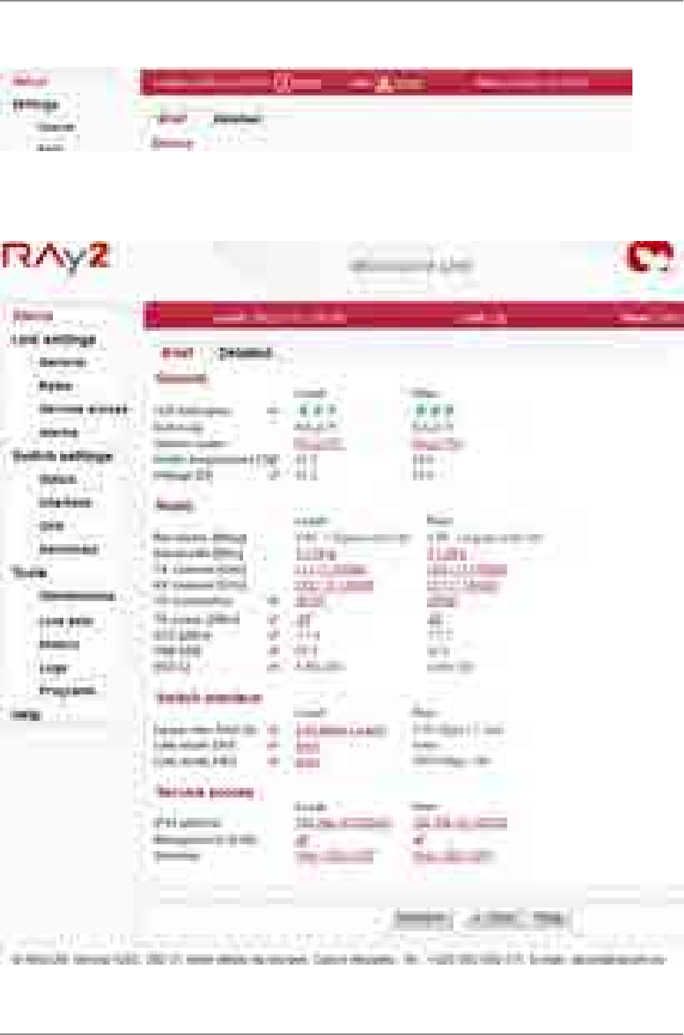
All link states except for the state of OK are highlighted with a triangle.:
Fig. 7.4: Status bar 2
Example of a complete page - status bar, menu and control buttons:
Fig. 7.5: Page example
RAy2 Microwave Link – © RACOM s.r.o.64
Configuration
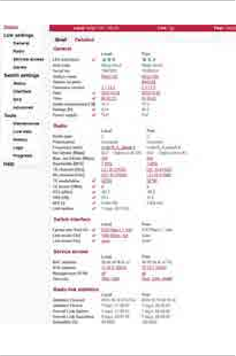
7.3. Status
Fig. 7.6: Menu Status
65© RACOM s.r.o. – RAy2 Microwave Link
Configuration

The Status menu provides basic information about local and remote station. Informations is valid the
moment the page is open, or the Refresh button is hit.
The Status – Brief tab shows only the most important values whereas the Status – Detailed tab
provides further details. Below is a list of all values according to the tab Status – Detailed.
The icon marks fields which are automatically updated with 30 sec period (or 1 sec when the Start
button is active).
7.3.1. Status - General
LED indicators Unit status indication
- Radio link OK
- Radio link interrupted
Green
Red
A - AIR
- System OKGreenS - SYS
- ETH1 port - Link 10/100/1000
- ETH2 port - Link 10/100/1000
Green
Orange
E - ETH
Unit type indicator.Unit code
Unit serial number.Serial no.
Station name assigned by user.Station name
Station location assigned by user.Station location
Unit’s firmware version.Firmware version
The internal real-time clock. The clock is set manually or it is synchronized
with NTP server and set for both units.
Date, Time
Temperature inside the unit (on the modem board).Inside temperature [°C]
Unit’s power supply voltage level.Voltage [V]
The power supply input the unit is powered from.
PoE - unit is powered via Ethernet cable plugged into port "ETH1+POE".
AUX - unit is powered via DC cable plugged into port "P".
Power supply
7.3.2. Status - Radio
Radio unit type: L (Lower) or U (Upper) part of the frequency band.Radio type
Horizontal or vertical polarization based on the physical installation. Indic-
ates the polarization of the received signal. Local and Peer are indicated
separately. The proper position of the cable is sideways down.
Notice for RAy2-17 and RAy2-24 links: One side of the link must be installed
in vertical polarization and the other in horizontal polarization.
Polarization
Displays the currently used frequency table in format <name:version>.Frequency table
Current transfer capacity of radio channel for user data.Net bitrate [Mbps]
The maximum RF channel capacity according to installed feature key.Max. net bitrate [Mbps]
One of the standard channel widths can be selected. This parameter must
be set identically in local and remote.
Bandwidth [MHz]
Used channels. Both number of the channel and frequency in GHz are
listed.
TX and RX channel [GHz]
Modulation type currently used for transmitting. When adaptive modulation
is enabled, the ACM letters are displayed as well as information about
TX modulation
RAy2 Microwave Link – © RACOM s.r.o.66
Configuration

maximum permitted modulation: “current modulation ACM / maximum
modulation”
Current output power on the RF channel in dBm. If ATPC is enabled, the
ATPC letters are displayed as well as information about maximum permitted
power: “current power ATPC / maximum power”
TX power [dBm]
Received signal strength. If ATPC is enabled, the ATPC letters are dis-
played as well as information about threshold value for activation of power
RSS [dBm]
67© RACOM s.r.o. – RAy2 Microwave Link
Configuration

control loop: “current RSS ATPC / threshold RSS”
Signal to Noise Ratio. If ATPC is enabled, the ATPC letters are displayed
as well as information about threshold value for activation of power control
loop: “current SNR ATPC / threshold SNR”
SNR [dB]
Bit Error Rate is registered at the receiving end; instantaneous value.BER [-]
Time elapsed since the current link connection has been established.Link uptime
7.3.3. Status - Switch interface
Egress rate limit Air Status of the Egress rate limitter on the Air interface. The traffic can be
limitted according to bits per second or frames per second.
Message format for bits per second: "xx.xx Mbps Ly auto" where:
Egress speed limit.xx.xx Mbps
L1/L2/L3 which Ethernet layer is used for speed calculation.Ly
gives information about active Speed guard function.
auto
Message format for frames per second: "xx.xx fps" where:
Egress frames per second limit.xx.xx fps
Status of ethernet interface. Current bit rate (10 = 10BASE-T, 100 =
100BASE-TX and 1000 = 1000BASE-T) and state of duplex (FD = full du-
plex, HD = half duplex).
Link mode Eth1, 2
7.3.4. Status - Service access
HW address of the Ethernet module.MAC address
IP address in the standard dotted decimal notation, including the bit width
of netmask after the forward slash.
IPv4 address
Service access via VLAN management only.Management VLAN
Services enabled for unit management and monitoring (Web, Telnet, SSH,
SNMP, NTP).
Services
7.3.5. Status - Radio link statistics
Information on statistical data:
Time of log clearing.Statistics Cleared
Period of log refresh.Statistics Period
Radio link statistics:
Overall time the link has been connected.Overall Link Uptime
Overall time the link has been disconnected.Overall Link Downtime
The ratio of Uptime and Downtime.
Reliability [%]
Current time the link has been connected.Current Link Uptime
The longest downtime period recorded.The Longest Drop
Length of the last link interruption.The Last Drop
Number of link interruptions.Number of Drops
RAy2 Microwave Link – © RACOM s.r.o.68
Configuration
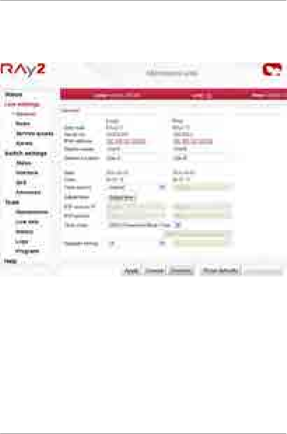
7.4. Link settings
7.4.1. General
Setup of general parameters of the link.
Fig. 7.7: Menu Link settings – General
Unit type indicator.Unit code
Unit serial number.Serial no.
IP address in the standard dotted decimal notation, including the bit width
of netmask after the forward slash.
IPv4 address
Station name assigned by user.Station name
Station location assigned by user.Station location
The internal real-time clock. The clock is set manually or it is synchronized
with NTP server and set for both units.
Date, Time
Time synchronization source setup. Manual setup or NTP protocol use.
For easier diagnostics of link operation, it is recommended to use the NTP
time synchronization.
Time source
69© RACOM s.r.o. – RAy2 Microwave Link
Configuration
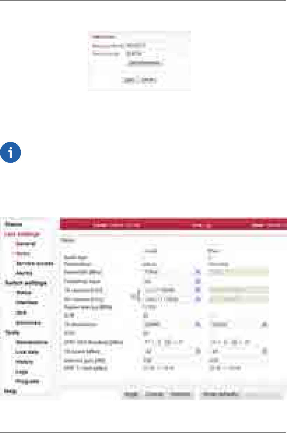
Manual time setup. Use the dialog box to manually set the current date
and time. You can copy time from browser (local PC).
Adjust time
IP address of the time synchronization server.NTP source IP
Time synchronization interval.NTP period
Time zoneTime zone
Enable daylight saving timeDaylight saving
Note
When the time zone and/or daylight saving time is changed, the original values set in the
RAy unit are kept. The actual change takes place after OS restart in order to prevent unex-
pected states related with local time change.
7.4.2. Radio
Setup of general parameters of the radio link.
Fig. 7.8: Menu Link settings – Radio
RAy2 Microwave Link – © RACOM s.r.o.70
Configuration

Radio unit type: L(ower) or U(pper) part of the frequency band.Radio type
Horizontal or vertical polarization based on the physical installation. Indic-
ates the polarization of the received signal. Local and Peer are indicated
separately. The proper position of the cable is sideways down.
Notice for RAy2-17 and RAy2-24 links: One side of the link must be installed
in vertical polarization and the other in horizontal polarization.
Polarization
One of the standard channel widths can be selected. This parameter must
be set identically in local and remote.
Bandwidth [MHz]
Enable manual input (if supported). TX and RX frequencies [GHz] are
manually entered. It is possible to disconnect the TX-RX lock and select
Frequency input
TX and RX channels individually. Corresponding channels at peer unit are
set automatically.
TX and RX channels are selected from a list of channels. The basic con-
figuration has the TX and RX options interconnected. In this case the basic
TX channel [GHz]
RX channel [GHz] duplex spacing between channels is preserved and by selecting one
channel, the other three are defined as well. For units operating in free
bands, it is possible to disconnect the TX-RX lock and select TX and RX
channels individually. Corresponding channels at peer unit are set auto-
matically.
NOTE: Non-standard duplex setting leads to non-effective use of the
spectrum.
Information about duplex spacing of TX and RX channel.Duplex spacing [MHz]
Enable automatic control of modulation.ACM
Modulation level for TX channel. You can select in range from QPSK (high
sensitivity for difficult conditions) to 256QAM (high speed under appropriate
TX modulation
conditions). With ACM enabled the modulation will automatically operate
from QPSK to the selected modulation.
Enable automatic control of RF power.
Power is regulated towards lower level while maintaining signal level high
enough not to affect current degree of modulation.
ATPC
The ATPC algorithm controles the output power according to RSS of the
peer unit. The lowest allowed RSS (the threshold) is approx. 10 dBm above
ATPC RSS threshold
[dBm]
declared sensitivity for BER 10-6. If necessary, it is possible to use this
parameter to move the threshold slightly up or down.
RF output power. With ATPC enabled this parameter defines maximum
RF power level.
TX power [dBm]
Valid only for RAy2-17 and RAy2-24 links.
Gain of used antenna. It is used to calculate approximate EIRP.
Antenna gain [dBi]
Valid only for RAy2-17 and RAy2-24 links.
Approximate calculation of EIRP. Number on the right shows the allowed
EIRP limit. Sign between numbers gives information on compliance /
noncompliance with allowed EIRP limits.
EIRP ?= limit [dBm]
71© RACOM s.r.o. – RAy2 Microwave Link
Configuration
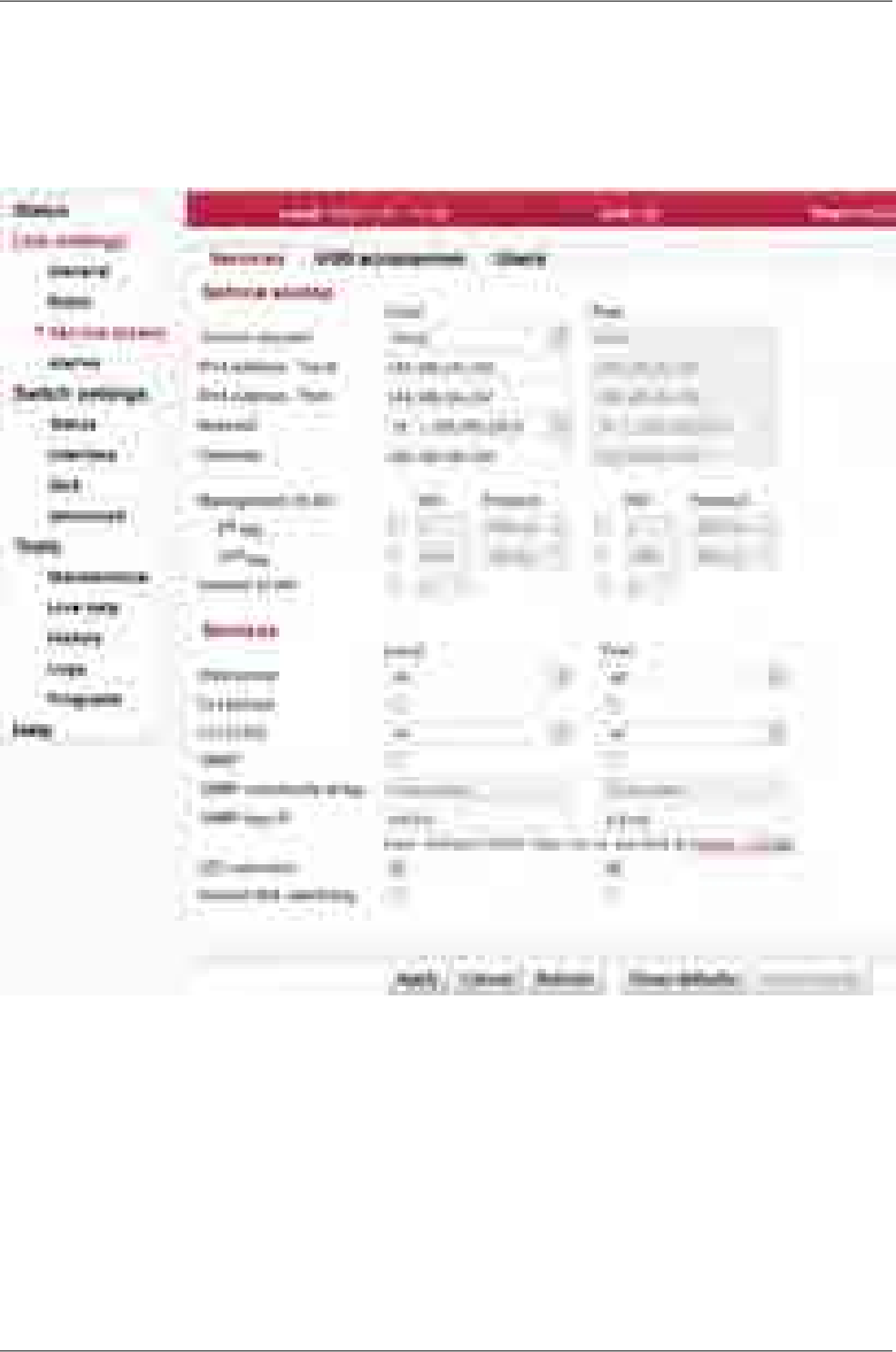
7.4.3. Service access
Services
Access routes for link configuration.
Fig. 7.9: Menu Link settings – Service access – Services
There are two modes of accessing the internal management system of the microwave
link: standard and direct
Service
channel
standard:
Both units are configured with the separate IP addresses, Netmasks, Gateways and
Management VLANs. IP addresses of both units doesn't have to belong in to the
same sub-net. The Internal VLAN is required to encapsulate the internal service traffic
between both units of the microwave link. There are additional internal service ad-
dresses used for this internal service traffic (see IPv4 address - Local section for
further details).
RAy2 Microwave Link – © RACOM s.r.o.72
Configuration

direct:
Both units are configured with the separate IP addresses but with the same Netmask,
Gateway and the Management VLAN. IP addresses of both units must belong in
to the same sub-net. There is no need for Internal VLAN to handle the internal service
traffic between both units of the microwave link. No additional internal service ad-
dresses exist.
NOTE: It is strongly recommended to use Management VLAN to encapsulate and
prioritize the management traffic when the direct mode is selected. If the Management
VLAN is not used (while in direct mode), the internal service traffic is NOT prioritized.
Service IP address, by default 192.168.169.169 for L unit and 192.168.169.170 for U
unit. Four addresses 169.254.173.236/30 are used for internal communication. Must
IPv4 address
- Local
not be used as service IP address. Those four addresses are not used while Service
channel is set to direct mode.
Unknown
IP address For easier identification of service IP address, RAy is equipped with LLDP protocol. This
protocol sends a broadcast every 60 seconds with the following information:
IP addressManagement address
Serial numberSystem Description
Type (e.g. RAY2-17-L)Chassis Subtype
IEEE 802.1 - Port and Protocol VLAN ID
Port and Protocol VLAN Identifier: (e.g. 300 (0x012C))
but only if Management VLAN is enabled
The message can be recorded and converted into a readable form using an LLDP client.
A suitable tool for this purpose is Wireshark IP traffic analyzing tool, with free licenses
available for both Windows and Linux. To locate the message easily, use the Capture
filter "ether proto 0x88cc” in Wireshark.
Management address of the Peer station. This address has to be set up when the
Service channel is set to direct mode.
IPv4 address
- Peer
Mask for service access, 24 by default.Netmask
Default gateway for service access; empty by default.Gateway
Enables access via VLAN management. Blocks access for https, ssh and telnet con-
figuration via untagged packets (without VLAN) making only VLAN access possible.
VLAN management is off by default.
WARNING:
By enabling VLAN management, ALL accesses are blocked for configuration using
normal (untagged) LAN! During tests, you may enable VLAN management on one
Management
VLAN
unit only (if the Service channel = standard). Then it is possible to access the link via
LAN and VLAN either directly or via radio link.
VLAN management id, by default 1. This field must have a value entered even when
VLAN management is not active.
VID
Protocol 802.1q or 802.1adProtocol
73© RACOM s.r.o. – RAy2 Microwave Link
Configuration

Valid only for Service channel = standard: The RAy uses one VLAN id for internal
service communication between both units.
There are two situations when it might be necessary to change the Internal VLAN id:
- Conflict within user data flow when the same VLAN id is already present within a
data flow.
- Conflict with the internal management address of another RAy unit located at the
same site and connected in the same LAN segment.
NOTE: The Ethernet frames within this service channel are marked with IEEE 802.1p
priority class "7". Default parameters for QoS and Egress queue control are pre-set
to prioritize this service communication channel.
Internal VLAN
Allows access via web server (for HTTP and HTTPS protocol).
WARNING: after disabling access via web server, you will not be able to access the
unit using a web browser!
Web server
Enables access via telnet protocol. Provides access to CLI (Command Line Interface)
for simple telnet clients. Disabled by default.
CLI (telnet)
Enables access via SSH protocol. Provides secure access to CLI. If preventing unau-
thorized access to the unit is the number one priority, leave only this server on.
CLI (SSH)
Enabling SNMP server. Off by default.SNMP
SNMP community string. Can contain both lower and uppercase letters, numbers,
four characters . : _ - and can be up to 256 characters long.
SNMP com-
munity string
Address for sending SNMP traps. It is possible to record up to 3 addresses separated
by commas.
SNMP trap IP
Enable LED status indicators on the body of the unit. You can turn off all LEDs with
this option.
LED indicators
Watching over connection of both link units. In case of prolonged failure (10 min) a
cold restart is performed (the equivalent of turning off the power). Off by default.
Internal link
watchdog
RAy2 Microwave Link – © RACOM s.r.o.74
Configuration
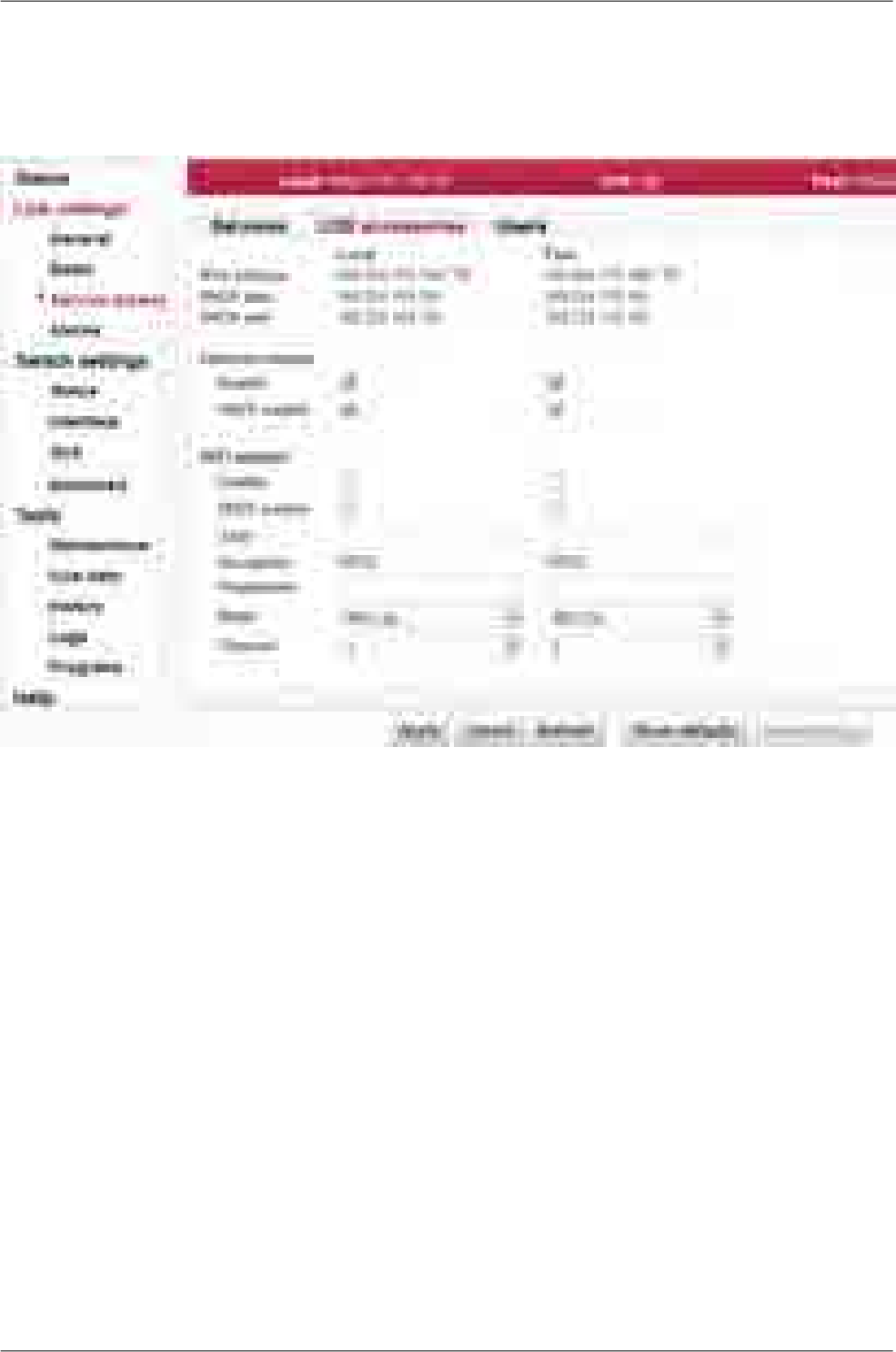
USB accessories
USB service connector can be used as a service port to the Local unit only.
USB to Ethernet and USB to WiFi adapters can be used.
Fig. 7.10: Menu Link settings – Service access – USB accessories
Unit service management address when connecting via USB port.IPv4 address
DHCP range for dynamic address allocation of the management client
connected via USB port.
DHCP start
DHCP end
USB to Ethernet adapter operation Enable/Disable.Ethernet adapter enable
DHCP server for the client(s) connected via the USB to Ethernet adapter.Ethernet adapter DHCP
enable
USB to WiFi adapter operation Enable/Disable.WiFi adapter enable
DHCP server for the client(s) connected via the USB to WiFi adapter.WiFi adapter DHCP
enable
Service WiFi SSID can be max 32 characters long.WiFi SSID
Service WiFi encryption is WPA2.WiFi encryption
Service WiFi passphrase has to be 8-64 characters long. The WiFi will not
start until it is defined.
WiFi passphrase
Service WiFi mode can be IEEE 802.11n or IEEE 802.11gWiFi mode
IEEE 802.11n - channels 1-9
IEEE 802.11g - channels 1-13
WiFi channel
75© RACOM s.r.o. – RAy2 Microwave Link
Configuration

Users
List and setup of users. Example menu of the cli_super level user.
Fig. 7.11: Menu Link settings – Service access – Users
Within the default Factory Settings one user is defined in the system. This user has username admin
and password admin and is assigned the highest level of permissions cli_super. This user then assigns
other users to the system along with their level of permissions.
Service access has three levels of permissions. Numbers of users that can be defined in the system:
No of usersPermissions
10cli_guest
10cli_admin
2cli_super
cli_supercli_admincli_guestPermissions defined in the system
YesNoNoCreate new user
YesYesYesChange own password
YesNoNoDelete user *
YesNoNoCopy (Mirror) permissions local to peer
YesYesNoConfigure and modify link settings
* The system prevents the user from deleting both cli_super accounts.
The logged on user is shown in the top right of the screen. There can be different users on either end
of the link.
Important
It is strongly recommended that the default password admin is changed. Similarly all other
users should change their password. Using the CLI, it is appropriate to supplement the SSH
key.
RAy2 Microwave Link – © RACOM s.r.o.76
Configuration

List of users on Local and Peer stations.Local, Peer
This name is entered at Login to log into the link management.Username
Group User group to which the user belongs.
Read Onlycli_guest
Configure and modify link settingscli_admin
Configure and modify user accounts and link settingscli_super
Information about whether user has a passwordPassword
Information about whether user has at least one ssh key defined.SSH key
Note
More users concurrently
If two or more users work concurrently on the unit any change of configuration settings
should be applied by all users. This applies to the menu Link settings which works with both,
Local and Peer parameters. Notification to other users:
If one user sends the Apply command, other users will receive a message: Configuration
changed, please go to Link settings and click Refresh. Other users can only use the Apply
command after refreshing Link Settings.
77© RACOM s.r.o. – RAy2 Microwave Link
Configuration
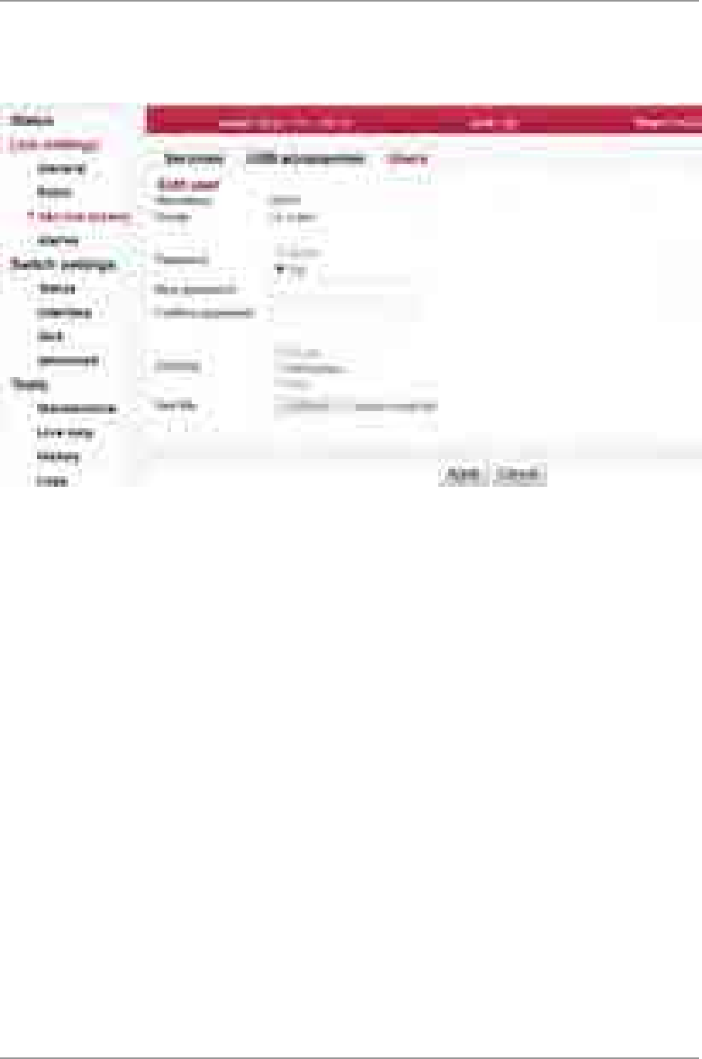
Edit use
Clicking Edit next to a username opens a screen with configuration of the given account.
Fig. 7.12: Menu Link settings – Service access – Users – edit
User nameUsername
The group to which this user will belong.Group
Password can be set or deleted.
Delete – User will not have a password. The user will only be able
to log in with an ssh key. In order to delete the password, you must
first upload the ssh key.
Set – Password settings.
Password
New password.New password
Repeat password.Confirm password
Working with ssh key.
Delete – Clear all ssh keys from user account.
Set/replace – Add a new key. If there already was any key(s), it will
be overwritten.
Add – Add a new key. You can enter multiple ssh keys in this way.
SSH key
Insert key file.Key file
Save the menu content by clicking on the button Apply.
Backup user
The user settings can be backed up, see Tools / Maintenance / Backup.
RAy2 Microwave Link – © RACOM s.r.o.78
Configuration

Delete user
Users at level cli_super have a Delete button next to each user. Delete a user using this button
without being asked to confirm deletion. Users at level cli_super cannot both be deleted.
Add user
The button is located on the bottom bar.
For level cli_super users, the Add user button is active. Use it to create a new user within any
group.
Name of new user.Username
The group to which this user is assigned.Group
Password for this user.New password
Repeat password.Confirm password
If you want the user to have access using ssh protocol and identity
verification using ssh key, enter the ssh key here.
SSH key
Create a new user account by clicking on the button Apply.
Mirror users
The button is located on the bottom bar.
For level cli_super users, the Mirror users button is active. This function will copy all user accounts
from Local unit to Peer unit. All existing user accounts on the Peer unit are deleted.
79© RACOM s.r.o. – RAy2 Microwave Link
Configuration
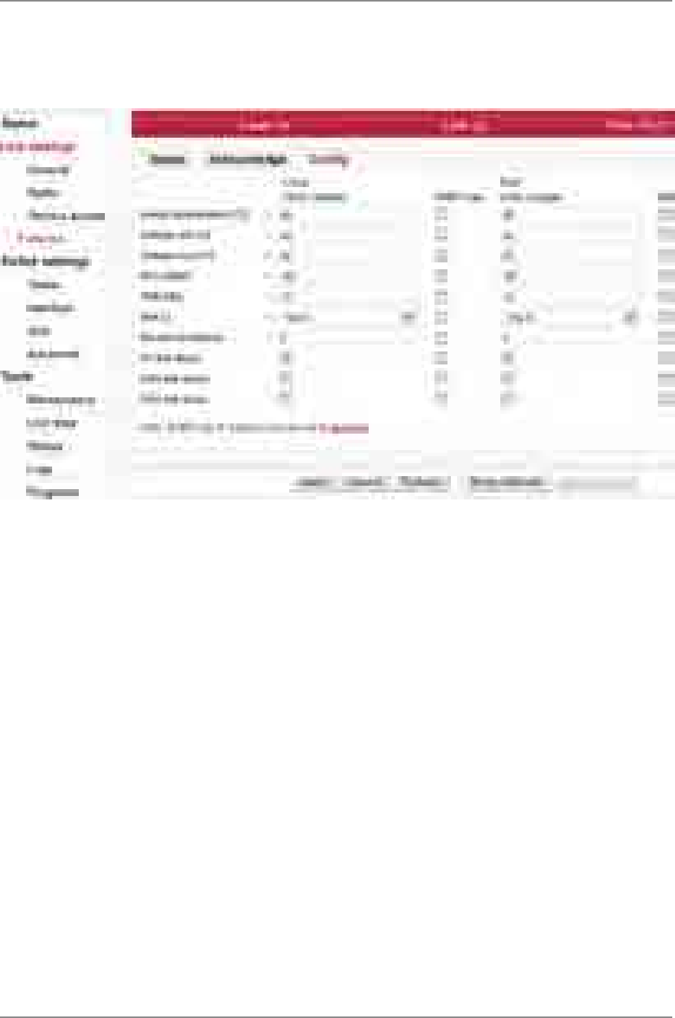
7.4.4. Alarms
Alarms Config
Fig. 7.13: Menu Link settings – Alarms – Config
The diagnostic system of the link monitors the operation of the unit.
It generates various output of events - system warnings and alarms. The event is always written to the
system log and indicated in the status bar and Alarms-Status screen. Some events have adjustable
thresholds. Events with no adjustable thresholds may or may not be Enabled. If they are not Enabled,
the system event is not activated even if the system status is changed.
If the event goes above or below the set parameter limits or a link goes down or up, you can choose
to send an SNMP trap.
descriptiondefaultalarm
Temperature inside the unit (on the modem board.)>80Inside temper. [°C]
Lower threshold of supply voltage.<40Voltage min [V]
Upper threshold of supply voltage. There is the same SNMP trap
(same OID) both for Voltage min and max.
>60Voltage max [V]
Received Signal Strength.<−80RSS [dBm]
Signal to Noise Ratio.<10SNR [dB]
Bit Error Rate registered at the receiving end; instantaneous value.>10e−6
BER [-]
The system warning is generated when the current transfer capacity of
radio channel is lower than the threshold set in this parameter.
0Net bitrate [Mbps]
Interruption of radio link.tickedAir link down
RAy2 Microwave Link – © RACOM s.r.o.80
Configuration
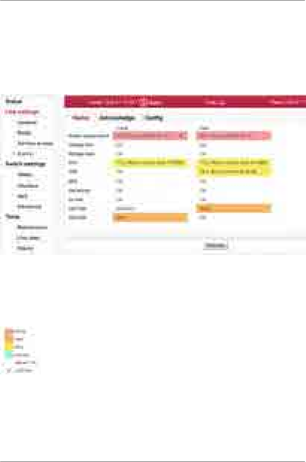
Corresponding user Eth link (Eth1/Eth2) on station interrupted.
NOTE: The EthX link system alarm can only be activated if this alarm
is Enabled. When the alarm is not Enabled, the EthX link alarm on
Eth link down
Status screen is always OK regardless of the current status of the Eth-
ernet link.
Loss of transmit power (not applicable for RAy2-17 neither RAy2-24).RF power fail
Alarms Status
Fig. 7.14: Menu Link settings – Alarms – Status
Overview of alarms
All system alarms are listed on this screen. Inactive alarms are colored white with an "OK" text label.
Active alarms are colored according to the severity of the alarm (see below) with a text message de-
scribing the measured value status.
Fig. 7.15: Alarm severity scale
81© RACOM s.r.o. – RAy2 Microwave Link
Configuration
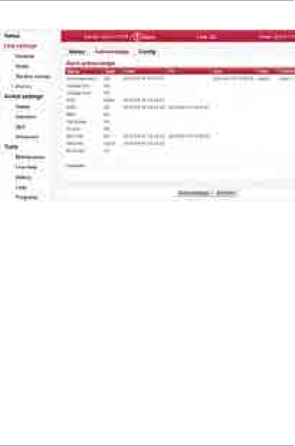
Alarms Acknowledge
Fig. 7.16: Menu Link settings – Alarms – Acknowledge
Alarm acknowledgement is a way to allow the operator to confirm the system is in alarm state. Only
an active alarm can be acknowledged.
Multiple selection of active alarms (to acknowledge groups of alarms) can be performed using Shift or
Ctrl keys.
Alarm identification. The following alarms can appear:
Inside temperature, Voltage min, Voltage max, RSS, SNR, BER, Net bitrate, Air
link, Eth1 link, Eth2 link, RF power
Name
There are three possible alarm states:
OK ... No alarm (alarm is inactive) or alarm disabled.
Ack ... Alarm is active and acknowledged.
Alarm ... Alarm is active and is not acknowledged.
State
Time stamp when the alarm occured.From
Time stamp when the alarm expired (returned to normal conditions).To
Time stamp when the alarm was acknowledged.
Time stamp format: yyyy-MM-dd hh:mm:ss
Ack
Name (login) of the user who acknowledged the alarm.User
The comment field can be used to add user defined comments when 'alarm ac-
knowledge' is performed. Use this comment to describe important details of the
Comment
alarm status. The comment can be up to 50 characters long. Special characters
are not allowed.
The alarm can be acknowledged multiple times with different comments. Every
acknowledgement is written to the internal memory and is visible in the alarm log.
RAy2 Microwave Link – © RACOM s.r.o.82
Configuration
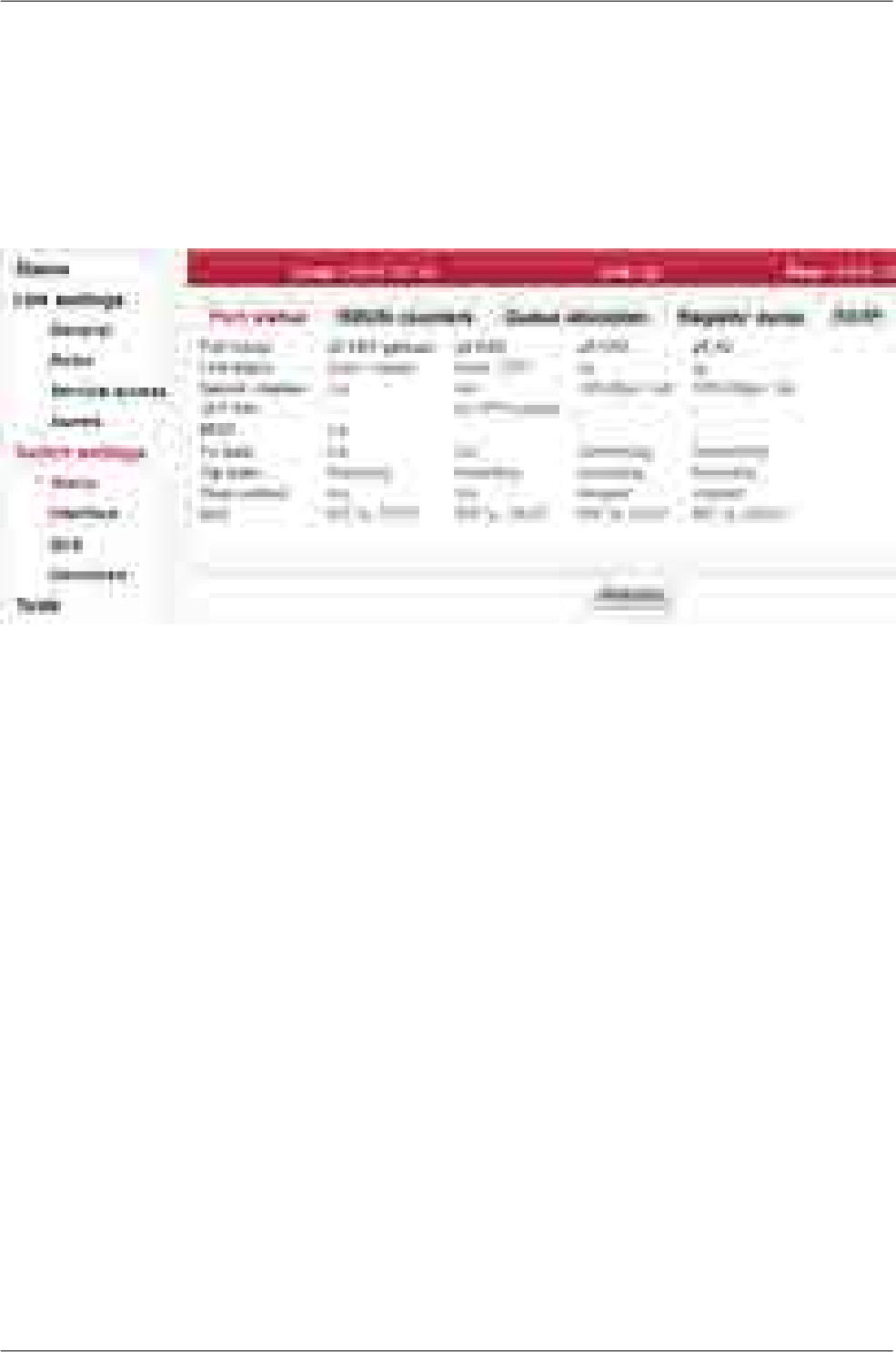
7.5. Switch settings
7.5.1. Status
Port status
The unit internal Ethernet switch port status
Fig. 7.17: Menu Switch settings - Port status
Port name Identification of the internal switch port. The switch ports are connected to an external
port or to an internal device (radio modem, management CPU).
The external port (with RJ45 interface) labeled "ETH1+POE". Port 2.
The external port (with SFP interface) labeled "ETH2". Port 4.
The internal port to management CPU. It is physical port number 5.
The internal port to radio modem, i.e. link to the peer unit. Port 6.
Eth1
Eth2
CPU
Air
Link status Ethernet link status can be
no link signal detecteddown / type
link signal detectedup / type
The type of the physical layer is indicated after the slash
metallic Ethernet interfacecopper
SFP module can be either optic or metallicSFP
Speed
/ duplex Ethernet link Speed and duplex.
10/100/1000 Mbps.Speed:
full/halfDuplex:
SFP info Information about the (optionally) inserted SFP module. The three different types of
SFP modules can be used:
dual mode with LC connectorFibre
single mode with LC connectorFibre
83© RACOM s.r.o. – RAy2 Microwave Link
Configuration

with RJ45 connectorCopper
There can be one of the following scenarios:
messagescenario
The SFP vendor string read out of SFP module. The vendor, model,
connector (RJ45/LC) and wavelength values are shown. Separate
SFP OK
window with more detailed information can be opened by clicking
the more... link.
No SFP moduleNo SFP
n/aread error
–no SFP
option
Status of the internal crossover of Ethernet cables. (MDIX = internally crossed pairs,
MDI = direct connection, N/A means an unknown state).
MDIX
Tx state Port transmitting status can be
Normal port operationtransmitting
Port transmitter is paused due to Pause frames receptionpaused
Flow control Mechanism for temporarily stopping the transmission of data on an Ethernet network.
Enabling flow control allows use of buffers of connected active network elements for
leveling uneven flow of user data. For correct operation it is necessary to also enable
Flow control on the connected device. Flow control is handled by sending Pause
frames to the connected device. See Flow control and Pause limit parameters.
Flow control can be one of the following values:
Flow control is disabled.disabled
Flow control is enabled.enabled
Flow control is enabled and activated. The port has requested the
link partner not to send any more data (by sending Pause frames).
active
QoS Quality of Service status can be one of the following values:
QoS functions are disabled.disabled
QoS according to 802.1p is enabled.802.1p
QoS according to DSCP is enabled.DSCP
QoS according to 802.1p and DSCP is enabled. The 802.1 prefer
tag is selected.
802.1p,DSCP
QoS according to 802.1p and DSCP is enabled. The DSCP prefer
tag is selected.
DSCP,802.1p
RAy2 Microwave Link – © RACOM s.r.o.84
Configuration
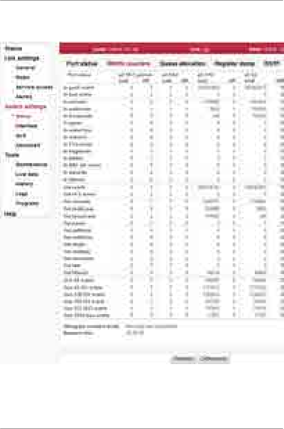
RMON counters
The unit internal Ethernet switch RMON counters
Fig. 7.18: Menu Switch settings - RMON counters
The Remote Network MONitoring (RMON) MIB was developed by the IETF to support monitoring and
protocol analysis of LANs.
85© RACOM s.r.o. – RAy2 Microwave Link
Configuration

Port name Identification of the internal switch port. The switch ports are connected to an external
port or to an internal device (radio modem, management CPU).
The external port (with RJ45 interface) labeled "ETH1+POE". Port 2.
The external port (with SFP interface) labeled "ETH2". Port 4.
The internal port to management CPU. It is physical port number 5.
The internal port to radio modem, i.e. link to the peer unit. Port 6.
Eth1
Eth2
CPU
Air
The Internal switch port RMON counters
These counters provide a set of Ethernet statistics for frames received on ingress and transmitted on
egress.
Ingress statistics counters
The sum of lengths of all good Ethernet frames received, that is
frames that are not bad frames.
In good octets
The sum of lengths of all bad Ethernet frames received.In bad octets
The number of good frames received that have a Unicast destina-
tion MAC address.
In unicasts
The number of good frames received that have a Multicast destin-
ation MAC address.
NOTE: This does not include frames counted in In broadcasts nor
does it include frames counted in In pause.
In multicasts
The number of good frames received that have a Broadcast destin-
ation MAC address.
In broadcasts
The number of good frames received that have a Pause destination
MAC address.
In pause
Total frames received with a length of less than 64 octets but with
a valid FCS.
In undersize
Total frames received with a length of more than MaxSize octets
but with a valid FCS.
In oversize
Total frames received with a CRC error not counted in In fragments,
In jabber or In MAC RX errors.
In FCS errors
Total frames received with a length of less than 64 octets and an
invalid FCS.
In fragments
Total frames received with a length of more than MaxSize octets
but with an invalid FCS.
In jabber
Total frames received with an RxErr signal from the PHY.In MAC RX
errors
Total number of frames that normally would have been forwarded,
but could not be due to a lack of buffer space.
In discards
Total number of good frames that were filtered due to ingress switch
policy rules.
In filtered
Egress statistics counters
The sum of lengths of all Ethernet frames sent from this MAC.Out octets
RAy2 Microwave Link – © RACOM s.r.o.86
Configuration

The number of frames transmitted with an invalid FCS. Whenever
a frame is modified during transmission (e.g., to add or remove a
Out FCS errors
tag) the frame’s original FCS is inspected before a new FCS is
added to a modified frame. If the original FCS is invalid, the new
FCS is made invalid too and this counter is incremented.
The number of frames sent that have a Unicast destination MAC
address.
Out unicasts
The number of good frames sent that have a Multicast destination
MAC address.
NOTE: This does not include frames counted in Out broadcasts
nor does it include frames counted in Out pause.
Out multicasts
The number of good frames sent that have a Broadcast destination
MAC address.
Out broadcasts
The number of Flow Control frames sent.Out pause
The total number of successfully transmitted frames that experi-
enced no collisions but are delayed because the medium was busy
Out deffered
during the first attempt. This counter is applicable in half-duplex
only.
The number of collision events seen by the MAC not including
those counted in Out Single, Multiple, Excessive, or Late. This
counter is applicable in half-duplex only. See Auto negotiation.
Out collisions
The total number of successfully transmitted frames that experi-
enced exactly one collision. This counter is applicable in half-duplex
only.
Out single
The total number of successfully transmitted frames that experi-
enced more than one collision. This counter is applicable in half-
duplex only.
Out multiple
The number frames dropped in the transmit MAC because the
frame experienced 16 consecutive collisions. This counter is applic-
able in half-duplex only.
Out excessive
The number of times a collision is detected later than 512 bits-times
into the transmission of a frame. This counter is applicable in half-
duplex only.
Out late
Total number of good frames that were filtered due to egress switch
policy rules.
Out filtered
Frame size histogram counters
Total frames received (and/or transmitted) with a length of exactly
64 octets, including those with errors.
Size 64 octets
Total frames received (and/or transmitted) with a length of between
65 and 127 octets inclusive, including those with errors.
Size 65-127
octets
Total frames received (and/or transmitted) with a length of between
128 and 255 octets inclusive, including those with errors.
Size 128-255
octets
Total frames received (and/or transmitted) with a length of between
256 and 511 octets inclusive, including those with errors.
Size 256-511
octets
Total frames received (and/or transmitted) with a length of between
512 and 1023 octets inclusive, including those with errors.
Size 512-1023
octets
87© RACOM s.r.o. – RAy2 Microwave Link
Configuration

Total frames received (and/or transmitted) with a length of between
1024 and MaxSize (see MTU parameter) octets inclusive, including
those with errors.
Size 1024-max
octets
Histogram
counters
mode
Frame size histogram counters can count received and/or transmitted octets. The mode
of histogram counters is indicated here.
Measure
time This is the time interval, the diff column is valid for. The diff column shows the difference
of the actual value of the counters at the moment of pressing the Difference button and
the value of the counters at the moment of pressing the Refresh button.
Refresh
Difference In another way: The Difference counter reference value can be reset by pressing the
Refresh button. The time point at which the Difference counter sample is triggered and
the diff value is calculated is defined by pressing the Difference button.
The total column always shows the actual values. It is refreshed either by pressing the
Refresh and also the Difference button.
RAy2 Microwave Link – © RACOM s.r.o.88
Configuration

Queue allocation
Fig. 7.19: Menu Switch settings - Queue allocation
Free queue Free Queue Size Counter. This counter reflects the current number of unallocated buffers
available for all the ports [buffers].
Port name Identification of the internal switch port. The switch ports are connected to an ex-
ternal port or to an internal device (radio modem, management CPU).
The external port (with RJ45 interface) labeled "ETH1+POE". Port 2.
The external port (with SFP interface) labeled "ETH2". Port 4.
The internal port to management CPU. It is physical port number 5.
The internal port to radio modem, i.e. link to the peer unit. Port 6.
Eth1
Eth2
CPU
Air
Ingress ... This counter reflects the current number of reserved Ingress buffers assigned to this port
[buffers].
Egress ... This counter reflects the current number of Egress buffers switched to this port. This is
the total number of buffers across all priority queues [buffers].
Queue 0~3
[buffers] Those counters reflect the current number of Egress buffers switched to this port for indi-
vidual priority queues [buffer].
89© RACOM s.r.o. – RAy2 Microwave Link
Configuration

Register dump
Fig. 7.20: Menu Switch settings - Register dump
The exact contents of the internal switch configuration and diagnostic registers can be listed for dia-
gnostic purposes. All registers are separated into several groups.
Groups Global switch parameters.Globals
Global port related parameters.All ports
Ports Port specific parameters.
Registers Registers contents is listed in hexadecimal notation.
RAy2 Microwave Link – © RACOM s.r.o.90
Configuration
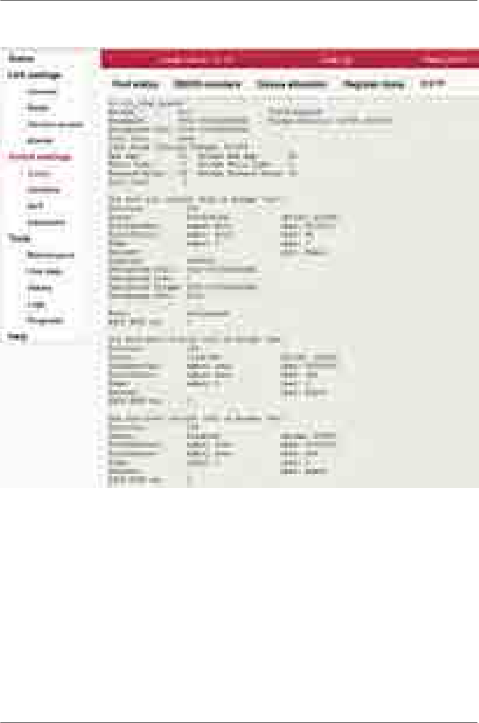
RSTP
Fig. 7.21: Menu Switch settings - RSTP
RSTP service status
91© RACOM s.r.o. – RAy2 Microwave Link
Configuration
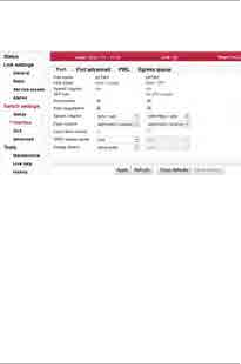
7.5.2. Interface
Port
Port settings
Fig. 7.22: Menu Switch settings - Port
Phyter is responsible for Ethernet signal conversion between wire (e.g. CAT7 cable) and internal switch
bus.
Port name Identification of the internal switch port. The switch ports are connected to an ex-
ternal port or to an internal device (radio modem, management CPU).
The external port (with RJ45 interface) labeled "ETH1+POE". Port 2.
The external port (with SFP interface) labeled "ETH2". Port 4.
Eth1
Eth2
Link status Ethernet link status can be
no link signal detecteddown / type
link signal detectedup / type
The type of the physical layer is indicated after the slash
metallic Ethernet interfacecopper
SFP module can be either optic or metallicSFP
Speed / duplex Ethernet link Speed and duplex.
10/100/1000 MbpsSpeed
full/halfDuplex
SFP info Information about the (optionally) inserted SFP module. The three different types
of SFP modules can be used:
dual mode with LC connectorFibre
RAy2 Microwave Link – © RACOM s.r.o.92
Configuration

single mode with LC connectorFibre
with RJ45 connectorCopper
There can be one of the following scenarios:
messagescenario
The SFP vendor string read out of SFP module. The vendor,
model, connector (RJ45/LC) and wavelength values are shown.
SFP OK
Separate window with more detailed information can be opened
by clicking the more... link.
No SFP moduleNo SFP
n/aread error
–no SFP
option
Port enable The port can be enabled or disabled.
WARNING: When the port is disabled, no communication is possible through
this port.
Auto negotiation Auto-Negotiation is an Ethernet procedure by which two connected devices choose
common transmission parameters, such as speed, duplex mode and flow control.
In this process, the connected devices first share their capabilities regarding these
parameters and then choose the highest performance transmission mode they
both support.
The device supports three types of Auto-Negotiation:
10/100/1000BASE-T Copper Auto-Negotiation. (IEEE 802.3 Clauses 28 and
40)
1000BASE-X Fiber Auto-Negotiation (IEEE 802.3 Clause 37)
SGMII Auto-Negotiation (Cisco specification)
Auto-Negotiation provides a mechanism for transferring information from the local
unit to the link partner to establish speed, duplex and Master/Slave preference
during a link session.
Auto-Negotiation is initiated upon any of the following conditions:
Power up reset
Hardware reset
Software reset
Restart Auto-Negotiation
Transition from power down to power up
The link goes down
The 10/100/1000BASE-T Auto-Negotiation is based on Clause 28 and 40 of the
IEEE 802.3 specification. It is used to negotiate speed, duplex and flow control
over CAT5 (or higher) UTP cable. Once Auto-Negotiation is initiated, the device
determines whether or not the remote device has Auto-Negotiation capability. If
so, the device and the remote device negotiate the speed and duplex with which
to operate.
If the remote device does not have Auto-Negotiation capability, the device uses
the parallel detect function to determine the speed of the remote device for
100BASE-TX and 10BASE-T modes. If a link is established based on the parallel
93© RACOM s.r.o. – RAy2 Microwave Link
Configuration

detect function, it is then required to establish the link at half-duplex mode only.
Refer to IEEE 802.3 clauses 28 and 40 for a full description of Auto-Negotiation.
1000BASE-X Auto-Negotiation is defined in Clause 37 of the IEEE 802.3 specific-
ation. It is used to auto-negotiate duplex and flow control over fibre cable.
If the PHY enables 1000BASE-X Auto-Negotiation and the link partner does not,
the link cannot linkup. The device implements an Auto-Negotiation bypass mode.
SGMII Auto-Negotiation. SGMII is a de-facto standard designed by Cisco. SGMII
uses 1000BASE-X coding to send data as well as Auto-Negotiation information
between the PHY and the MAC. However, the contents of the SGMII Auto-Negoti-
ation are different than the 1000BASE-X Auto-Negotiation.
WARNING: If one device provides Auto-negotiation and the other works with a
manual link parameters settings (i.e. without Auto-negotiation) the link operates
in half-duplex mode. If the manual settings is set to full-duplex, the Out collisions
may occur.
Speed / duplex Ethernet link speed and duplex mode can be selected. Both parameters can be
either auto negotiated or set manually. When the Auto negotiation parameter is
disabled, only manual setting of the speed and duplex is possible. In most cases
it is better to enable the auto negotiation and use "auto / auto" speed and duplex
settings.
There are two possibilities to force the link to operate in specific speed and duplex:
Auto negotiation enabled. Select the desired Speed / duplex. The auto negoti-
ation process advertises only this specified link mode. The link partner is asked
to use it.
Auto negotiation disabled. Select the desired Speed / duplex. The link is set to
this specified link mode. The link partner has to be set manually to the same
mode.
Flow control The flow control mechanism is handled by sending Pause frames to the connected
device. There are several modes of Pause frames generation:
Pause frames disabled.no pause
Pause frames transmission and reception enabled.symmetric
Pause frames transmission enabled, reception disabled.asymmetric
(send)
Pause frames reception enabled, transmission disabled.asymmetric
(receive)
Auto-Negotiation has to be enabled to enable Pause frames sending and receiving.
Force
flow control If the Auto-Negotiation is disabled and Flow control is required, the Force flow
control parameter can be used. Flow control is turned on without having to be Auto-
Negotiated
1000T master
mode The 1000BASE-T master/slave mode can be manually configured.
Automatic MASTER/SLAVE configuration.auto
Manual configure as MASTER.master
Manual configure as SLAVE.slave
Energy detect The device can be placed in energy detect power down modes by selecting either
of the two energy detect modes. Both modes enable the PHY to wake up on its
RAy2 Microwave Link – © RACOM s.r.o.94
Configuration

own by detecting activity on the Ethernet cable. The energy detect modes only
apply to the copper media.
In the first sense mode, if the PHY detects energy on the line, it starts to Auto-Ne-
gotiate sending FLPs (Fast Link Pulse) for 5 seconds. If at the end of 5 seconds
the Auto-Negotiation is not completed, then the PHY stops sending FLPs and goes
back to monitoring received energy. If Auto-Negotiation is completed, then the PHY
goes into normal 10/100/1000 Mbps operation. If during normal operation the link
is lost, the PHY will re-start Auto-Negotiation. If no energy is detected after 5
seconds, the PHY goes back to monitoring received energy.
In sense pulse mode, the PHY sends out a single 10 Mbps NLP (Normal Link Pulse)
every one second. Except for this difference, this is identical to the previous mode
(sense) operation. If the device is in sense mode, it cannot wake up a connected
device; therefore, the connected device must be transmitting NLPs. If the device
is in sense pulse mode, then it can wake a connected device.
Offoff
Sense and periodically transmit NLP (Energy Detect+TM).sense pulse
Sense only on Receive (Energy Detect).sense
95© RACOM s.r.o. – RAy2 Microwave Link
Configuration
Port advanced
The unit internal Ethernet switch Port settings
Fig. 7.23: Menu Switch settings - Port advanced
Port name Identification of the internal switch port. The switch ports are connected to an external
port or to an internal device (radio modem, management CPU).
The external port (with RJ45 interface) labeled "ETH1+POE". Port 2.
The external port (with SFP interface) labeled "ETH2". Port 4.
The internal port to management CPU. It is physical port number 5.
The internal port to radio modem, i.e. link to the peer unit. Port 6.
Eth1
Eth2
CPU
Air
Label Custom port name.
Frame mode Ethernet Frame mode control defines the expected Ingress and the generated Egress
tagging frame format for this port as follows:
Normal Network mode uses industry standard IEEE 802.3ac Tagged
or Untagged frames. Tagged frames use an Ether Type of 0x8100.
normal
Ports that are expected to be connected to standard Ethernet devices
should use this mode.
Inactive options are not required.DSA
Provider mode uses user definable Ether Types per port (see Ether
type parameter) to define that a frame is Provider Tagged. Ports that
provider
are connected to standard Provider network devices, or devices that
use Tagged frames with an Ether Type other than 0x8100 should use
this mode.
Frames that ingress this port with an Ether Type that matches the port's
Ether Type parameter will be considered tagged, will have the tag's
VID and PRI bits assigned to the frame (i.e. they will be used for
RAy2 Microwave Link – © RACOM s.r.o.96
Configuration

switching and mapping), and will have the Provider Tag removed from
the frame. If subsequent Provider Tags are found following the 1st
Provider Tag, they too will be removed from the frame with their VID
and PRI bits being ignored. Modified frames will be padded if required.
Frames that ingress this port with an Ether Type that does not match
the Ether Type parameter will be considered untagged. The ingressing
frames are modified so they are ready to egress out Customer ports
(Normal Network Frame Mode ports) unmodified.
Frames that egress this port will always have a tag added (even if they
were already tagged). The added tag will contain this port's Ether Type
as its Ether Type. The PRI bits will be the Frame Priority FPri assigned
to the frame during ingress. The VID bits will be the source port's Default
VID bits (if the source port was in Normal Network mode), or the VID
assigned to the frame during ingress (if the source port was in Provider
mode).
Valid only for the "p5 CPU" port.ether
type DSA Ether Type DSA mode uses standard Marvell DSA Tagged frame in-
formation following a user definable Ether Type (see Ether type para-
meter). This mode allows the mixture of Normal Network frames with
DSA Tagged frames and is useful on ports that connect to a CPU.
Frames that ingress this port with an Ether Type that matches the port's
"Ether Type" will be considered DSA Tagged and processed accordingly.
The frame's Ether Type and DSA pad bytes will be removed so the
resulting frame will be ready to egress out Marvell DSA Tag Mode ports
unmodified. Frames that ingress this port with a different Ether Type
will be considered Normal Network Frames and processed accordingly.
Marvell DSA Tag control frames that egress this port will always get
the port's "Ether Type" inserted followed by two pad bytes of 0x00 before
the DSA Tag. Marvell DSA Tag Forward frames that egress this port
can egress just like the control frames (with the added Ether Type and
pad) or they can egress as if the port was configured in Normal Network
mode. This selection is controlled by the port's Egress Mode bits above.
Frame type Ethernet frame type (often called EtherType) is used to indicate which protocol is
encapsulated in the payload of an Ethernet Frame. This parameter is important when
one protocol is encapsulated to another protocol.
Examples:
CommentStandardEth. type
Double-tagged, Q-in-Q or C-tag stacking on C-tag. C-
tag in IEEE 802.1ad frames
IEEE 802.1q0x8100
S-TagIEEE 802.1ad0x88a8
S-Tag (backbone S-Tag)IEEE 802.1ah0x88e7
It is used very often. For example an old non-standard
802.1QinQ protocol uses this value.
-0x9100
See http://en.wikipedia.org/wiki/EtherType for futher details.
MTU [B] MTU determines the maximum frame size allowed to be received or transmitted from
or to a given physical port. This implies that a Jumbo frame may be allowed to be
97© RACOM s.r.o. – RAy2 Microwave Link
Configuration

received from a given input port but may or may not be allowed to be transmitted out
of a port or ports. The possible values are 1522, 2048 and 10240 Bytes.
NOTE: The definition of frame size is counting the frame bytes from MAC_DA
through Layer2 CRC of the frame.
Pause limit in
[frame] Limit the number of continuous Pause refresh frames that can be received on this
port (if full-duplex) or the number of 16 consecutive collisions (if half-duplex). When
a port has flow control enabled, this parameter can be used to limit how long this port
can be Paused or Back Pressured off to prevent a port stall through jamming.
The Flow Control on the port is (temporarily) disabled when the Pause refresh frames
count exceeds the value of this parameter.
Setting this parameter to 0 will allow continuous jamming to be received on this
port.
Pause limit out
[frame] Limit the number of continuous Pause refresh frames that can be transmitted from
this port – assuming each Pause refresh is for the maximum pause time of 65536
slot times. When full-duplex Flow Control is enabled on this port, this parameter is
used to limit the number of Pause refresh frames that can be generated from this
port to keep this port’s link partner from sending any data.
Clearing this parameter to 0 will allow continuous Pause frame refreshes to egress
this port as long as this port remains congested.
Setting this parameter to 1 will allow 1 Pause frame to egress from this port for
each congestion situation.
Setting this parameter to 2 will allow up to 2 Pause frames to egress from this
port for each congestion situation, etc.
Ignore Frame
checksum Ignore Frame checksum (FCS) - or in other words - Force good FCS in the frame. When
this parameter is not set (default behaviour), frames entering this port must have a good
CRC or else they are discarded. When this parameter is set, the last four bytes of frames
received on this port are overwritten with a good CRC and the frames are accepted by
the switch (assuming that the frame’s length is good and it has a destination).
RAy2 Microwave Link – © RACOM s.r.o.98
Configuration
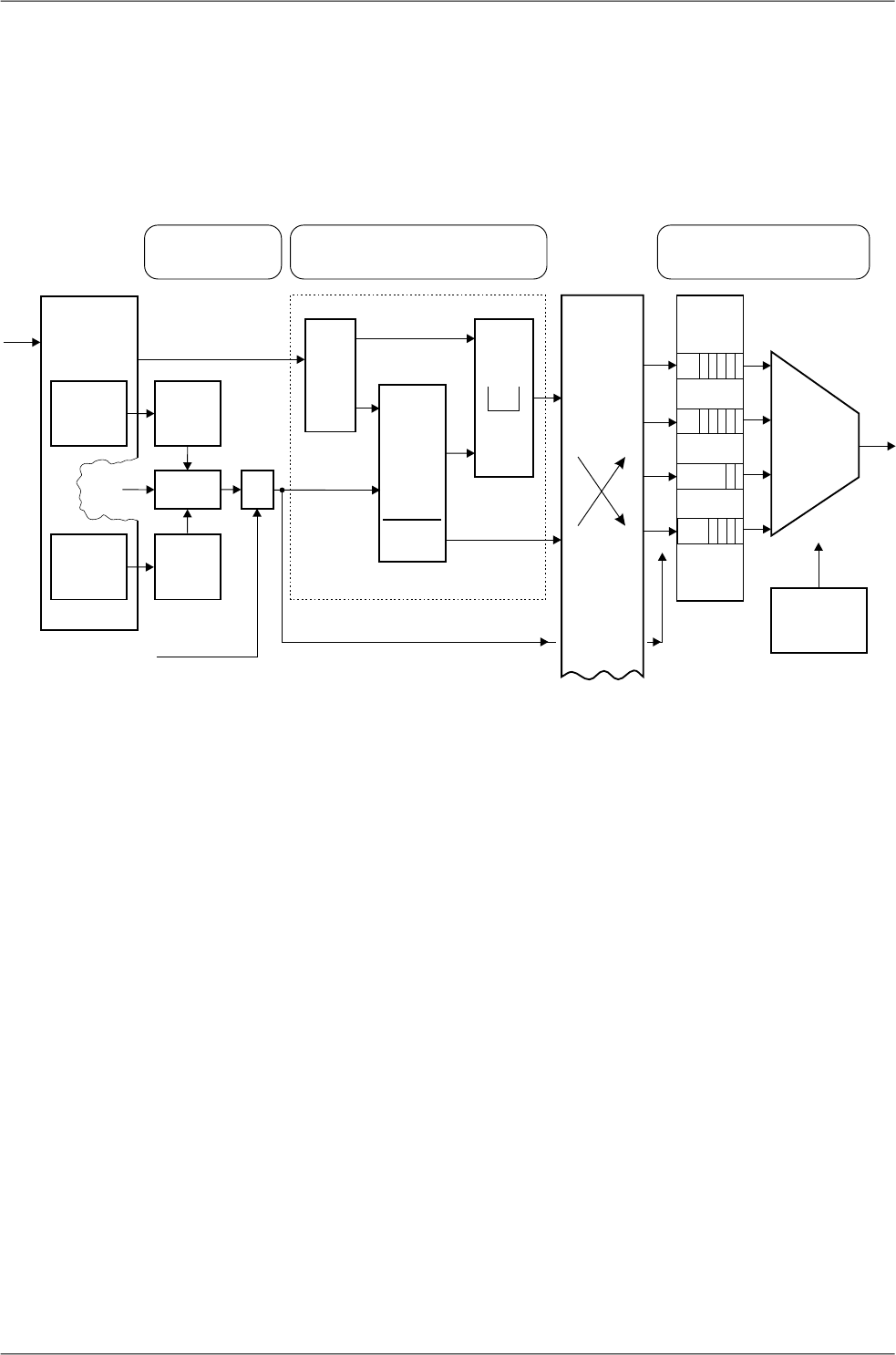
PIRL
PIRL (Port based Ingress Rate Limiting) has the task of arranging the transfer of frames; ensuring as
few frames as possible are discarded and that ports are not blocked.
Diagram of framework processing options are available within the QoS, PIRL and Egress queue control
menus:
IP header
3-rd layer
6 bits
port
port
L2
switching
block
0
VLAN
2-nd layer
3 bits
QoS
Weight table
Scheduling
mode
Rate
[kbps]
[fps]
Queue
default
queue
802.1p
Mapping
Tra fic
type
fFrame
type
Leaky
bucket
Default
AND/OR
Priority
rate
DSCP
Mapping
Prefer
lenght, type
QPri
QPri
Pri 3–0
Bucket 0–4
Priority
overriding
1. VLAN based
2. SA based
3. DA based
3
2
1
0
QoS PIRL
FRAME
Egress queue control
3
2
1
0
Def.
prior.
bucket
params.
follow other ports
Fig. 7.24: PIRL and queues
Frame
The frame comes via port, has a certain length and MAC addresses SA and DA. The IP header carries
the DSCP priority and may also carry the 802.1p VLAN priority.
QoS
The Queue priority (QPri) is created based on preferences within the DSCP or 802.1p priority. This
priority takes values from 0 to 3, and controls the processing of frames inside the switch.
• Untagged frames are provided with 802.1p priority by default.
• Priorities may be remapped.
• The priority can also be overwritten by the Advanced menu priority derived from a VLAN, SA and/or
DA addresses.
The Frame priority (FPri) is processed in a similar manner. Frame coming from the network and frame
being sent to the network is marked by this priority.
PIRL
Between the port and the common switch there may be between 1 and 5 “flow restrictors” working in
parallel according to the schedule “leaky bucket”. These are called “Resource”. This is analogous to
99© RACOM s.r.o. – RAy2 Microwave Link
Configuration

the container which is intermittently replenished by tokens according to incoming frames and is continu-
ously emptied. Regulatory measures are implemented at a certain height to ensure the bucket does
not overflow.
PIRL - Edit section of this menu is made up of several groups of parameters:
• Resource identification.
• Resource capacity, transfer byte into tokens.
• Method of counting frames.
• Regulatory interventions (drop frame - reduce feeding)
• Selecting frames (all - by priority QPri - by type).
The above mentioned parameters are used to allocate part of a frame to each Resource. Their passage
is regulated thus avoiding network congestion. If there is a framework that does not match the filter of
any Resource, this then passes to the switch without restrictions.
Switching block
In this block (L2-switch) each frame is routed to a designated port according to the Advanced menu.
Egress queue
Block output queues. Each port receives frames from the L2 switch through 4 queues (No. 3-0). The
highest priority has a queue No. 3. The frames are organized into queues according to their priorities
QPri.
The Method to empty queues is selected by the parameter Scheduling Mode. The emptying rate is
governed by the Rate limit parameter.
A Frame sent from the port to the network can be identified by priority FPri, although it is also possible
to change its tag: see menu VLAN - Egress mode.
RAy2 Microwave Link – © RACOM s.r.o.100
Configuration

Port based ingress rate limiting, see also the Functional diagram
Fig. 7.25: Menu Switch settings - PIRL
The device supports per port TCP/IP ingress rate limiting along with independent Storm prevention.
Port based ingress rate limiting accommodates information rates from 64 Kbps to 1 Mbps in increments
of 64 Kbps, from 1 Mbps to 100 Mbps in increments of 1 Mbps and from 100 Mbps to 1000 Mbps in
increments of 10 Mbps.
In addition to this, the device supports Priority based ingress rate limiting. A given ingress rate resource
can be configured to track any of the four priority traffic types. One of the popular schemes for imple-
menting rate limiting is a leaky bucket. The way a leaky bucket scheme works is that the bucket drains
tokens constantly at a rate called Committed Information Rate (CIR) and the bucket gets replenished
with tokens whenever a frame is allowed to go through the bucket. All calculations for this bucket are
done in tokens. Therefore, both bucket decrementing and incrementing is performed using tokens (i.e.,
frame bytes are converted into bucket tokens for calculation purposes).
The device supports a color blind leaky bucket scheme.
The traffic below Committed Burst Size limit (CBS Limit) is passed without any further actions. If the
traffic burst were to continue and the bucket token depth approaches closer to the Excess Burst Size
limit (EBS Limit) by less than the CBS Limit, then a set of actions are specified. Note that if the frame
gets discarded then the equivalent number of tokens for that frame will not get added to the bucket.
There are the two default ingress limiting rules already configured in the switch default configuration.
They limit the maximum allowed ARP traffic comming to the CPU port to 10Mbps from Eth1 and 10Mbps
from Eth2 ports.
101© RACOM s.r.o. – RAy2 Microwave Link
Configuration

Possibleactions:
-Discardtheframe
-Passtheframeand
sendflowcontrolframe
backtothesource
-Passthetraffic
EBS:ExcessBurstSize
CBS:CommittedBurstSize
CIR:CommittedInformationRate
Allbucketcalculations
doneinunitsoftokens
Passedframesize
basedtokenupdate
EBSLimit
CBSLimit
CIR
Fig. 7.26: Leaky bucket
Primary key The live data icon indicates which parameter field is taken as the unique identifier
in the database. This field entry ensures each record is unique and must not be
duplicated.
Ports Eth1, Eth2, CPU, Air. See Port status.Port name
Id Each port can be assigned up to five different ingress rate resources.
Each resource defines a rule (filter) for the incoming frame. If the rule is met, the
frame is affected (as set by the EBS limit action parameter). If the incoming frame
doesn't meet any rule, it is not affected by PIRL. The frame is accepted and forwar-
ded further to the switch engine.
CIR (estimated) The Committed Information Rate (CIR) is dependent on the Bucket Rate factor and
the Bucket increment.
The calculation is estimated as the real data throughput depends on frame size.
The Accounted bytes parameter affects this as well.
The formula for the CIR (in bits per second) is as follows: CIR = a * BRF / BI.
Where "a" is constant, which is 12 500 000 for Accounted bytes="frame", and is
100 000 000 for Accounted bytes="layer1". BRF is Bucket Rate factor and BI is
Bucket increment.
Bucket rate
factor This is a factor which determines the amount of tokens that need to be decremented
for each rate resource decrement (which is done periodically based on the Com-
mitted Information Rate).
Bucket
increment Bucket increment (BI) indicates the amount of tokens that need to be added for
each byte of the incoming frame.
Mode Rate type or Traffic type of rate limiting. See Bucket type parameter.
Edit Press Edit to edit selected PIRL resource.
Delete Press Delete to delete selected PIRL resource.
Add resource Press Add resource button to add another PIRL resource.
RAy2 Microwave Link – © RACOM s.r.o.102
Configuration
PIRL - resource configuration
Fig. 7.27: Menu Switch settings - PIRL Resource
Each port can be assigned up to five different ingress rate resources.
103© RACOM s.r.o. – RAy2 Microwave Link
Configuration

Each resource defines a rule (filter) for the incoming frame. If the rule is met, the frame is affected (as
set by the EBS limit action parameter). If the incoming frame doesn't meet any rule, it is not affected
by PIRL. The frame is accepted and forwarded further to the switch engine.
Port name Identification of the internal switch port. The switch ports are connected to an ex-
ternal port or to an internal device (radio modem, management CPU).
The external port (with RJ45 interface) labeled "ETH1+POE". Port 2.
The external port (with SFP interface) labeled "ETH2". Port 4.
The internal port to management CPU. It is physical port number 5.
The internal port to radio modem, i.e. link to the peer unit. Port 6.
Eth1
Eth2
CPU
Air
Id Each port can be assigned up to five different ingress rate resources.
Each resource defines a rule (filter) for the incoming frame. If the rule is met, the
frame is affected (as set by the EBS limit action parameter). If the incoming frame
doesn't meet any rule, it is not affected by PIRL. The frame is accepted and forwar-
ded further to the switch engine.
CIR (estimated) The Committed Information Rate (CIR) is dependent on the Bucket Rate factor and
the Bucket increment.
The calculation is estimated as the real data throughput depends on frame size.
The Accounted bytes parameter affects this as well.
The formula for the CIR (in bits per second) is as follows: CIR = a * BRF / BI.
Where "a" is constant, which is 12 500 000 for Accounted bytes="frame", and is
100 000 000 for Accounted bytes="layer1". BRF is Bucket Rate factor and BI is
Bucket increment.
Burst allocation
[b] The Burst allocation (BA) is dependent of the Bucket increment, the Committed
Burst Size limit and the Excess Burst Size limit.
The formula for the BA is as follows: BA = 8 * (EBS-CBS) / BI.
Where EBS is the Excess Burst Size limit, CBS is the Committed Burst Size limit
and BI is the Bucket increment.
The Burst allocation size should be less than switch internal memory which is 1Mb.
CBS min The minimum value for the CBS limit is related to the maximum frame size and
Bucket increment.
The CBS limit should always be bigger than the CBS min.
The calculation for CBS min is as follows:
CBS min = BI * MaxFrameSize [bytes].
Where BI is the Bucket increment.
If the CBS limit is lower than this value (i.e. to allow a large burst), then an ingress
stream composed of maximum sized frames may exceed the Committed Information
Rate. It is for this reason that we recommend the CBS limit value always stays
above the CBS min value. Also, the CBS limit should never exceed the EBS limit.
EBS limit Excess Burst Size limit.
The EBS limit should always be bigger than CBS limit. It is recommended that the
EBS limit be set to 16777200.
CBS limit Committed Burst Size limit. This indicates the committed information burst amount.
RAy2 Microwave Link – © RACOM s.r.o.104
Configuration

Bucket
rate factor This is a factor which determines the amount of tokens that need to be decremented
for each rate resource decrement (which is done periodically based on the Com-
mitted Information Rate).
Bucket
increment Bucket increment (BI) indicates the amount of tokens that need to be added for
each byte of the incoming frame.
Account
discarded
frames
This parameter decides whether the ingress rate limiting logic accounts for frames
that have been discarded by the queue controller due to output port queue conges-
tion reasons. To account for all frames coming into a given port associated with
this rate resource, this parameter needs to be set.
Account filtered
frames This parameter decides whether the ingress rate limiting logic accounts for frames
that have been discarded because of ingress policy violations. To account for all
frames coming into a given port associated with this rate resource, this parameter
needs to be set.
Management
non rate limit When this parameter is disabled all frames that are classified by the ingress frame
classifier as MGMT frames would be considered to be ingress rate limited as far
as this particular ingress rate resource is concerned.
When this parameter is enabled, all frames that are classified as MGMT frames
by the ingress frame classifier would be excluded from the ingress rate limiting
calculations for this particular ingress rate resource.
SA non rate limit When this parameter is enabled then SA ATU non rate limiting overrides can occur
on this port. An SA ATU non rate limiting override occurs when the source address
of a frame results in an ATU hit where the SA's MAC address returns an "Entry
state" with "static non rate limiting" value. When this occurs the frame will not be
ingress rate limited.
DA non rate limit When this parameter is enabled then DA ATU non rate limiting overrides can occur
on this port. A DA ATU non rate limiting override occurs when the destination ad-
dress of a frame results in an ATU hit where the DA's MAC address returns an
"Entry state" with "static non rate limiting" value. When this occurs the frame will
not be ingress rate limited.
Accounted
bytes This parameter determines which frame bytes are to be accounted for in the rate
resource's rate limiting calculations.
There are for different supported configurations:
Frame based configures the rate limiting resource to account for
the number of frames from a given port mapped to this rate re-
source.
frame
Preamble (8bytes) + Frame’s DA to CRC + IFG (inter frame gap,
12 bytes)
layer 1
Frame’s DA to CRClayer 2
Frame’s DA to CRC - 18 - 4(if the frame is tagged)layer 3
A frame is considered tagged if it is either Customer of Provider tagged during in-
gress.
EBS limit action This parameter controls what kind of action is performed when the EBS limit has
been exceeded. Three types of action can be selected:
The frame that was received on the port will get discarded.drop
105© RACOM s.r.o. – RAy2 Microwave Link
Configuration

In this mode an Ethernet flow control frame gets generated (if the
flow control is enabled for that port) and sent to the source port
flow control
but the incoming frame gets passed through the rate resource. If
the port is operating in half-duplex mode then the port gets jammed.
The frame that was received on the port is accepted even though
there are not enough tokens to accept the entire incoming frame.
accept
This mode is expected to be selected for TCP based applications.
It is not recommended for media streaming applications where
data timing is critical.
Flow control mode is expected to be programmed on ports that have a trusted flow
control mechanism available. The EBS limit action is a per-port characteristic. If a
port has multiple rate resource buckets then all buckets enabled are expected to
be programmed with the same EBS limit action.
Sampling mode This mode is used for sampling one out of so many frames/bytes that are being
monitored. The stream could be identified by the ingress engine as a Policy mirror
and packet sampling can be applied for that streeam using one of the rate resources.
In this mode, once the rate resource's "EBS Limit" is exceeded, the next incoming
frame from this port that is assigned to this resource gets sent out to the mirror
destination. After sending a sample frame, the token count within the rate resource
is reset to zero and the bucket increments continue for each subsequent frame
arrival.
The sampling mode is useful for limiting the number of Mirror frames sent to the
mirror destination.
Flow control
de-assertion This parameter controls the flow control de-assertion when EBS limit action is set
to generate a flow control message. There are two modes available:
Flow control gets de-asserted only when the ingress rate resource
has become empty.
empty
Flow control gets de-asserted when the ingress rate resource has
enough room to accept at least one frame of size specified by the
CBS limit.
For example, if the CBS limit is programmed to be 2k Bytes, then
the flow control will get de-asserted if there is at least 2k Bytes
worth of tokens available in the ingress rate resource.
CBS limit
Bucket type Any given bucket can be programmed to be aggregate rate based or traffic type
based.
Rate based ingress rate limit: Limits all types of traffic on the ingress port.
Traffic type based ingress rate limit: Limits a specific type of traffic on the ingress
port.
Mask operation This parameter controls whether an ingress frame must meet both Priority and
Frame type requirements to be counted for ingress rate calculations or if meeting
only one requirement is sufficient to be counted for ingress rate calculations for
this rate resource.
Priority Any combinations of the four queue priorities can be selected. Frames with marked
priority are accounted for in this ingress rate resource.
If there is no priority selected, priority of the frame doesn't have any affect on the
ingress rate limiting calculations done for this ingress rate resource.
RAy2 Microwave Link – © RACOM s.r.o.106
Configuration

Frame type Any of the following frame types can be selected to be tracked as part of the rate
resource calculations:
Management (MGMT), Multicasts, Broadcasts, Unicasts, Address Resolution Pro-
tocol (ARP), TCP Data, TCP Ctrl, UDP, Non-TCPUDP (covers IGMP, ICMP, GRE,
IGRP and L2TP), IMS, PolicyMirror, PolicyTrap, Unknown Unicasts or Unknown
Multicasts.
More than one frame type can be selected for a given rate resource.
107© RACOM s.r.o. – RAy2 Microwave Link
Configuration
Egress queue control
See also Output queue diagram.
Fig. 7.28: Menu Switch settings - Egress queue
Port name Identification of the internal switch port. The switch ports are connected to an ex-
ternal port or to an internal device (radio modem, management CPU).
The external port (with RJ45 interface) labeled "ETH1+POE". Port 2.
The external port (with SFP interface) labeled "ETH2". Port 4.
The internal port to management CPU. It is physical port number 5.
The internal port to radio modem, i.e. link to the peer unit. Port 6.
Eth1
Eth2
CPU
Air
Scheduling
mode Port's Scheduling mode.
The device supports strict priority, weighted round robin, or a mixture on a per
egress port selection basis.
In the strict priority scheme all top priority frames egress for a port until that priority’s
queue is empty, then the next lower priority queue’s frames egress, etc. This ap-
proach can cause the lower priorities to be starved out preventing them from
transmitting any frames but also ensures that all high priority frames egress the
switch as soon as possible.
In the weighted scheme an 8, 4, 2, 1 weighting is applied to the four priorities unless
an alternate weighting is programmed into the QoS Weights Table. This approach
prevents the lower priority frames from being starved out with only a slight delay
to the higher priority frames.
RAy2 Microwave Link – © RACOM s.r.o.108
Configuration

Some applications may require the top priority queue, or the top two priority queues
to be in a fixed priority mode while the lower queues work in the weighted approach.
All scheduling modes are selectable on a per port basis.
The port scheduling mode can be one of the following values:
Use a weighted round robin queuing scheme.weighted RRB
Use Strict for priority 3 and use weighted round robin for prior-
ities 2,1 and 0
strict pri 3
Use Strict for priorities 3 and 2 and use weighted round robin
for priorities 1 and 0
strict pri 3, 2
Use a Strict priority scheme for all prioritiesstrict
Speed guard The speed guard controls automatically the Egress data rate shaping according to
available capacity of the Air channel. The Air channel capacity check and the Egress
shaping adjustment takes place approx. once per 50 ms.
Count mode Egress rate limiting count mode. This parameter is used to control which bytes in
the transmitted frames are counted for egress rate limiting as follows:
The egress rate limiting is done based on frame count [fps] as
opposed to the byte count [kbps] of the packet.
frame
Preamble (8bytes) + Frame’s DA to CRC + IFG (inter frame gap,
12 bytes)
layer 1
Frame’s DA to CRClayer 2
Frame’s DA to CRC - 18 - 4(if the frame is tagged)layer 3
Only one tag is counted even if the frame contains more than one tag. A frame is
considered tagged if the egress frame going out onto the wire is tagged.
Rate [kbps] /
[fps] Egress data rate shaping. When Rate = 0 egress rate limiting is disabled.
NOTE: The Count mode parameter is used to control which bytes in the trans-
mitted frames are counted for egress rate limiting.
If the egress shaping is controlled by frame rate, the desired frame rate can vary
from 7.6k to 1.488M frames per second. Valid values are between 7600 and
1488000.
If the egress shaping is controlled by bit rate, the desired rate can vary from 64
kbps to 1 Gbps in the following increments:
Desired rate between 64 kbps and 1 Mbps in increments of 64 kbps
Desired rate between 1 Mbps to 100 Mbps in increments of 1 Mbps
Desired rate between 100 Mbps to 1 Gbps in increments of 10 Mbps
Therefore, the valid values are:
64, 128, 192, 256, 320, 384,..., 960,
1000, 2000, 3000, 4000, ..., 100000,
110000, 120000, 130000, ..., 1000000
Frame overhead
[B] Egress Rate Frame Overhead adjustment.
This parameter is used to adjust the number of bytes that need to be added to a
frame’s IFG (inter frame gap) on a per frame basis. This is to compensate for a
protocol mismatch between the sending and the receiving stations. For example
if the receiving station were to add more encapsulations to the frame for the nodes
109© RACOM s.r.o. – RAy2 Microwave Link
Configuration

further down stream, this per frame adjustment would help reduce the congestion
in the receiving station.
This adjustment, if enabled, is added to the Egress Rate Control’s calculated
transmitted byte count meaning Egress Rate Control must be enabled for this
Frame Overhead adjustment to work.
Weight table The weighted round robin alternate weighting can be defined here. The sequence
of the output queue numbers (0,1, 2 or 3) defines the sequence of the output queue
frame egressing. This sequence can be up to 128 items long.
RAy2 Microwave Link – © RACOM s.r.o.110
Configuration
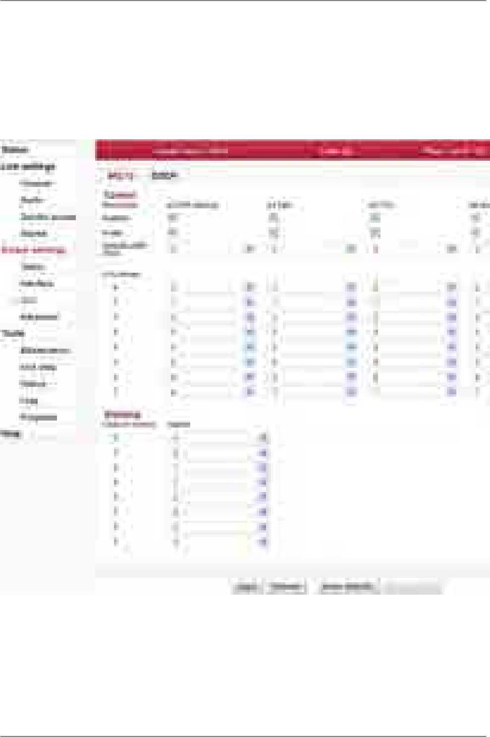
7.5.3. QoS
The QoS classification is handled in the switch Ingress block. The Ingress block does not perform the
QoS switching policy, which is the task of the Queue Controller.
See the Functional diagram.
802.1p
Fig. 7.29: Menu Switch settings - 802.1p
The IEEE 802.1p QoS technique also known as class of service (CoS), is a 3-bit field called the Priority
Code Point (PCP) within an Ethernet frame header when using VLAN tagged frames as defined by
IEEE 802.1Q. It specifies a priority value of between 0 and 7 inclusive that can be used by QoS discip-
lines to differentiate traffic. The value 0 is generally taken as the lowest priority and 7 as the highest
priority.
111© RACOM s.r.o. – RAy2 Microwave Link
Configuration

Port name Identification of the internal switch port. The switch ports are connected to an ex-
ternal port or to an internal device (radio modem, management CPU).
The external port (with RJ45 interface) labeled "ETH1+POE". Port 2.
The external port (with SFP interface) labeled "ETH2". Port 4.
The internal port to management CPU. It is physical port number 5.
The internal port to radio modem, i.e. link to the peer unit. Port 6.
Eth1
Eth2
CPU
Air
Enabled The QoS classification according to IEEE 802.1p priority bits is enabled/disabled.
Prefer Enable this parameter to force 802.p priority over DSCP.
When enabled, the DSCP Prefer parameter is automatically disabled.
Default traffic
class The IEEE 802.1q untagged frames (thus having no IEEE 802.1p priority) are treated
with this priority.
CoS remap The frame's IEEE 802.1p priority can be changed to other value.
Class of service Arranging individual priorities (coded in priority bits according to IEEE 802.1p) into
selected output queue (0..3).
RAy2 Microwave Link – © RACOM s.r.o.112
Configuration
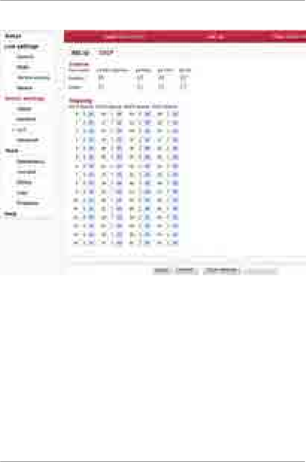
DSCP
Fig. 7.30: Menu Switch settings - DSCP
The DSCP stands for Differentiated services Code Point which is a 6-bit value stored within the IP
header. The QoS techniques using those bits are called DiffServ or Differentiated services.
Port name Identification of the internal switch port. The switch ports are connected to an ex-
ternal port or to an internal device (radio modem, management CPU).
The external port (with RJ45 interface) labeled "ETH1+POE". Port 2.
The external port (with SFP interface) labeled "ETH2". Port 4.
The internal port to management CPU. It is physical port number 5.
The internal port to radio modem, i.e. link to the peer unit. Port 6.
Eth1
Eth2
CPU
Air
Enabled The QoS classification according to DSCP priority bits is enabled/disabled.
Prefer Enable this parameter to force DSCP priority over 802.p.
When enabled, the IEEE 802.1p Prefer parameter is automatically disabled.
DSCP 0..63 Arranging individual priorities (coded in DS field of IP header) into selected output
queue (0..3).
113© RACOM s.r.o. – RAy2 Microwave Link
Configuration
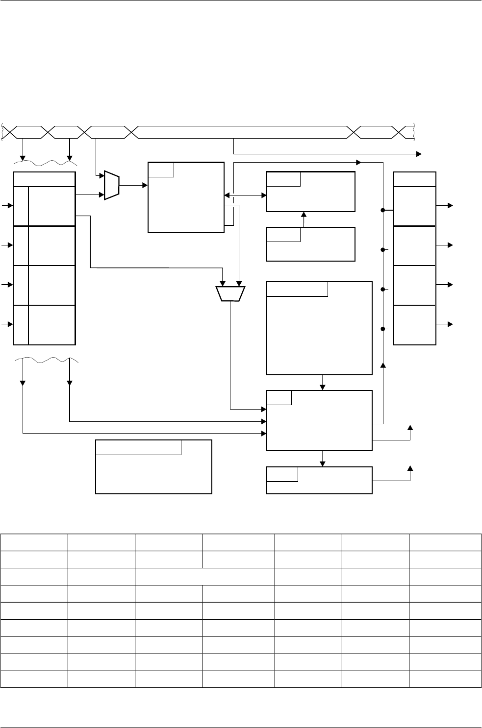
7.5.4. Advanced
According to the Advanced menu proceeds the deciding, through which port the framework should be
transmitted from RAy unit.
The processing of framework can be observed on the diagram and in the table. Table columns indicate
successive steps and in the rows there is hinted the development of framework parameters.
port
Trunk
ATU settings
MGMT multicast rules
Ports:
Learning, Hold1, ...
SA filtr
SA, DA prior. override
port association
ATU max. 8192
static / dynamic
SA, DA prior. override
trunk / port
Trunk
port
DPV
RSTP
time, portcost
state of ports
according to STP
VID override
SID
FID
enabled ports
egress tag
6 bit
Eth 1
Eth 2
CPU
Air
Def. VID
Def. FID
STU max. 64
VTU
SID
Air
VID
FID
SA
SA
FPri
Egress
mode
Egress
Ingress
Egress
mode
max. 4096
12 bit
802.1q
12 bit
VLAN def
DA
Monitoring, Policy
8 tests agction
normal
mirror
trap
discard
data
DA Tag Frame Data CRC
items items
items
VLAN
Member
CPU
E2
E1
Fig. 7.31: Advanced menu diagram
TrunkATUSTUVTUVLANFrame
idDA, SADA, SA
DA, SAby VLANby portQoS, DSCPQPri
iddef. VIDVIDVID
idSIDSID
idby VLANby portFID
idATU-TrunkTrunk
TrunkATU-PortRSTPby portport egress
Member tagEgress modetag egress
RAy2 Microwave Link – © RACOM s.r.o.114
Configuration

An indicative description of the function of each block:
Frame
An incoming frame contains the destination MAC address DA and the source address SA. The VLAN
802.1p priority can be contained in the Ethernet header and the DSCP priority in the IP header. If the
frame is a member of a VLAN, it carries it's VID number and 802.1q priority in the tag.
VLAN
A frame is received through ports Eth1, Eth2, Air or from microwave CPU. The head of the frame may
change at this time based on parameters set in the VLAN menu.
All untagged frames are assigned a VID. A tagged (VLAN) framework can have its own VID overwritten
by a default VID.
The packet priority can be ovewritten according to parameter menus QoS, VLAN and ATU.
The FID for searching in the ATU table is allocated to the frame within the VLAN menu (by the input
port) or from the corresponding VID in the VTU table.
Member parameter can limit the allowed output direction of ports.
Frames sent from a unit transfers through an output port. The Egress mode parameter bound to the
port either adds or removes the VLAN tag.
VTU
Values in the VID determine search results from the VTU table. These are created manually. The SID
index (enabled ports in terms of STP) FID index (for searching in the address table ATU) taken from
this search result are assigned to the frame. This FID will overwrite the FID from menu VLAN.
Based on this, the VTU can also overwrite the priority of this frame.
The permitted output ports and method of working with VLAN tag on the output are also defined here.
STU
The Spanning tree protocol in this table maintains the status of ports from the viewpoint of the authorized
network throughput and the learning of routing. Protocol MSTP is used.
Each VTU entry uses some of the entries in the STU. Entries in the ATU are created in accordance
with these assigned states.
The port state behaviour is determined by the STP.
ATU settings
Any assigned parameters dictate how the ATU table should be used.
The Global section of this menu provides for passage of MGMT frames (e.g. BPDU).
In the Port settings section, the behaviour of individual port is defined:
115© RACOM s.r.o. – RAy2 Microwave Link
Configuration

- Behaviour of the ATU table in terms of automatically creating records (Learning, Hold at 1, ATU refresh,
Learn limit).
- Discarding frames according to the source addresses.
- Handling frames with unfamiliar destination addresses.
- The frames' priority can be overridden by the SA or the DA.
ATU
The ATU table determines the output port on the RAy according to the DA in the frame.
Records are arranged according to the FID and the MAC addresses.
The table is created and maintained based on informations contained in incoming frames (learning).
Manual recording is also possible.
The record can be dynamic or static.
Priority frames with a static record can be overridden by the SA or DA.
The results of searching the ATU provide the set of output ports or trunk number.
RSTP
The RSTP demon turns off redundant paths through the network (switch ports), or re-activates them
in the case of failure in other branch.
The Global section of this menu contains switch priority for the RSTP and necessary time constants.
The Port settings section holds the value of each port as seen by the RSTP. This information indicates
if the RSTP shuts down or restarts a redundant port if a route is interrupted.
Trunk
The Trunk enables the distribution of data load on multiple ports. The ratio of distribution is determined
by parameter Balancing mode.
RAy2 Microwave Link – © RACOM s.r.o.116
Configuration

Abbreviations used in the Advanced menu.
DA, SA Destination and Source frame address (MAC)
LAN Local Area Network
VLAN Virtual LAN, menu of parameters related to the VLAN
VID VLAN network ID
VTU VLAN Table Unit - according to VID assignes SID and FID to the frame
SID Spanning tree ID - record number for STP
STP Spanning Tree Protocol - prevents a loop in the network
STU Spanning Tree Unit - parameters associated with STP
FID Forwarding Information Database number - according to this runs searching in the table
ATU Address Translation Unit - conversion FID and DA to number of output port
MGMT Management frames - service frames of the microwave link:
frames "ATU - Entry state = static management"
and frames "ATU settings - Reserved..."
BPDU Bridge Protocol Data Unit - frames used by STP protocol
802.1d Spanning tree protocol by ports
802.1s Spanning tree protocol by VLAN
802.1q tagging of frames (VLAN)
802.1p priority by 2-nd layer (tagged frames Ethernet)
DSCP Differentiated Services Code Point - priority by 3-rd layer (IP packet)
QoS Quality of Service
FPri Frame Priority - priority in the network
QPri Queue Priority - priority of the frame inside the switch
Trunk here in the sense of aggregation ethernet links - conjunction multiple ports into a single line
another meaning is VLAN aggregation lines - multiple VLANs on a single port
117© RACOM s.r.o. – RAy2 Microwave Link
Configuration
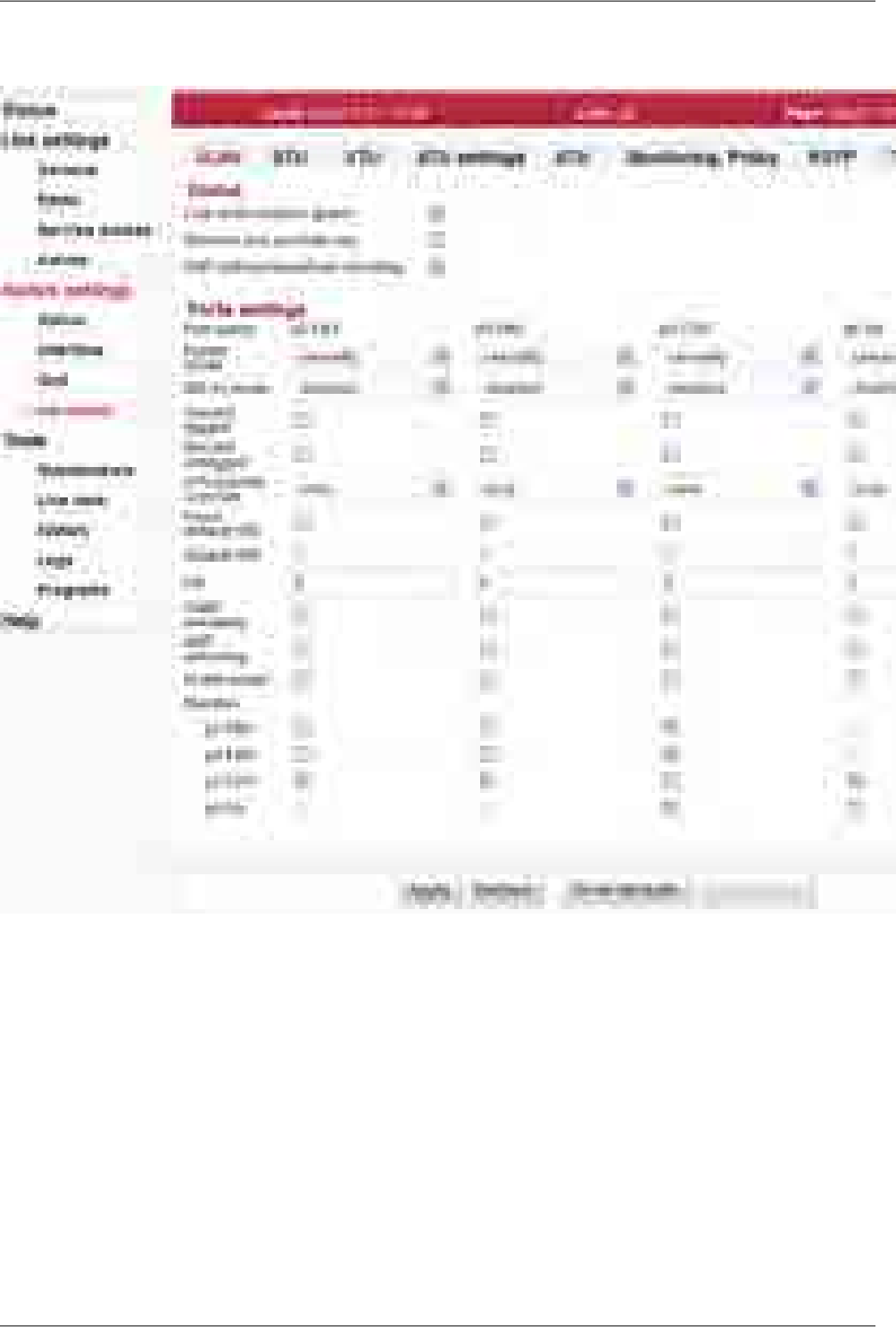
VLAN
Fig. 7.32: Menu Switch settings - Advanced - VLAN
Setup of VLAN related and global parameters.
Link
authorization
guard
Remote unit authorization must take place to ensure user data flow between both
units. See User manual Section 8.3.3, “Remote unit authorization” for more details.
The Link authorization guard parameter can be used to bypass this authorization re-
quirement.
Remote unit authorization is bypassed. User data flow through the
Air channel occurs even if the remote unit is not authorized.
Disabled
User data flow through the Air channel occurs only if the remote unit
is authorized – according to the Remote unit authorization procedure.
Enabled
RAy2 Microwave Link – © RACOM s.r.o.118
Configuration

Remove one
provider tag When this parameter is enabled and a port is configured as a Provider Port, recursive
Provider Tag stripping will NOT be performed. Only the first Provider Tag found on
the frame will be extracted and removed. Its extracted data will be used for switching.
When this parameter is disabled and a port is configured as a Provider Port, recursive
Provider Tag stripping will be performed. The first Provider Tag's data will be extracted
and used for switching, and then all subsequent Provider Tags found in the frame will
also be removed. This will only occur if the port's Ether type is not 0x8100 (recursive
Provider Tag removal cannot be performedSetup of VLAN related when the Provider's
Ether Type is equal to 0x8100).
ARP without
broadcast
checking
ARP frames must contain a Broadcast Destination address to be
able to access the CPU port.
Disabled
ARP frames only need an Ether type equal to 0x0806 and the frames
Destination Address can be any value to be able to access the CPU
Enabled
port. This supports Mirroring ARP replies that are destined to a uni-
cast address.
Port name Identification of the internal switch port. The switch ports are connected to an external
port or to an internal device (radio modem, management CPU).
The external port (with RJ45 interface) labeled "ETH1+POE". Port 2.
The external port (with SFP interface) labeled "ETH2". Port 4.
The internal port to management CPU. It is physical port number 5.
The internal port to radio modem, i.e. link to the peer unit. Port 6.
Eth1
Eth2
CPU
Air
Egress mode This parameter determines the make up of frames when they egress this port. The
Egress mode behaviour is affected by the Frame mode (menu Interface – Port ad-
vanced – Frame mode) parameter.
Frame mode ... normal:
Frames are transmitted unmodifiedunmodify
Remove the tag from any tagged frameuntag
Add a tag (e.g. according to Default VID ) to any untagged frame.
Ethernet frame type is set to 0x8100.
tag
not usedether type
tag
Frame mode ... provider:
Use this mode when Frame mode is set to provider.
unmodify
not useduntag
not usedtag
not usedether type
tag
Frame mode ... ether type DSA:
not usedunmodify
not useduntag
not usedtag
Add a tag (e.g. according to "Default VID") to any untagged frame.
Ethernet frame type is set according to "Ether type" parameter (menu
Switch settings - Interface - Port advanced).
ether type
tag
119© RACOM s.r.o. – RAy2 Microwave Link
Configuration

802.1q mode This parameter determines if 802.1q base VLANs are used along with port based
VLANs for this Ingress port. It also determines the action to be taken if an 802.1q
VLAN Violation is detected. VLAN barriers (both port based and 802.1q based) can
be bypassed by VLAN Tunnel.
Use Port Based VLANs only. The VID assigned to the frame is the
port's Default VID which is used as the VID in the Provider Tag if the
frame egresses a Provider port.
disabled
Enable 802.1q for this Ingress port. Do not discard Ingress Member-
ship violations and use the VLAN Table bits if the frames' VID is not
contained in the VTU.
The ingressing frames are not discarded and it doesn't matter if the
frames' VID is a member of the VTU.
fallback
Enable 802.1q for this Ingress port. Do not discard Ingress Member-
ship violation but discard the frame if its VID is not contained in the
VTU.
The ingressing frames' VID must be configured in the VTU to enable
it to ingress. The VTU Member tag parameter doesn't have any effect.
check
Enable 802.1q for this Ingress port. Discard Ingress Membership vi-
olations and discard frames whose VID is not contained in the VTU.
The ingressing frame is checked fully against the record in the VTU
table. The VID and the Member tag parameters are validated to allow
the frame to ingress.
secure
Discard
tagged When this parameter is enabled all non-MGMT frames that are processed as tagged
are discarded as they enter this switch port. Priority only tagged frames (with a VID
of 0x000) are considered untagged. This feature works whether 802.1q is enabled on
the port or not.
If the port is configured in Provide Mode and this parameter is enabled, frames that
contain an Ether Type that matches the port's PortEType (Ether type parameter) that
have a non-zero VID will be discarded.
Discard
untagged When this parameter is enabled all non-MGMT frames that are processed as untagged,
are discarded as they enter this switch port. Priority only tagged frames (with a VID
of 0x000) are considered untagged. This feature works whether 802.1q is enabled on
the port or not.
If the port is configured in Provide Mode and this parameter is enabled, frames that
don't contain an Ether Type that matches the port's PortEType (Ether type parameter)
that have a non-zero VID will be discarded.
VTU priority
override When this parameter is set to anything other than none, VTU priority overrides can
occur on this port. A VTU priority override occurs when the determined VID of a frame
results in a VID whose Use VID priority parameter is enabled. When this occurs three
(other than none) forms of priority overrides are possible:
Normal frame priority processing occurs.none
The VID priority value assigned to the frame's VID (in the VLAN
database) is used to overwrite the frame's previously determined
frame
FPri (frame priority). If the frame egresses tagged the priority in the
frame will be this new VID priority value - the frame is permanently
modified.
RAy2 Microwave Link – © RACOM s.r.o.120
Configuration

The VID priority value assigned to the frame's VID (in the VLAN
database) is used to overwrite the frame's previously determined
queue
QPri (queue priority). The QPri is used internally to map the frame
to one of the egress queues inside the switch. QPri override will not
affect the contents of the frame in any way.
Both the above overrides take place on the frame.frame+queue
The VTU Priority override has higher priority than the port's Default Priority and the
frame's IEEE and/or IP priorities. The priority determined by the frames' VID can
however be overridden by the frames' SA and/or DA Priority Overrides.
Force default
VID Force to use Default VID. When 802.1q is enabled on this port and this parameter is
enabled, all Ingress frames' VID are ignored and the Default VID is assigned and re-
placed into the frame (if the frame egresses tagged). When this parameter is disabled
all IEEE802.3ac Tagged frames with a non-zero VID use the frames' VID unmodified.
When 802.1q is disabled on this port, this bit has no effect.
Default VID Default VLAN Identifier. When 802.1q is enabled on this port the Default VID parameter
is used as the IEEE Tagged VID added to untagged or priority tagged frames during
egress that ingressed from this port. It is also used as a tagged frame's VID if the
frame's VID was 0x000 (i.e., it is a priority tagged frame) or if the port's Force Devault
VID is enabled.
When 802.1q is disabled on this port, the Default VID field is assigned to all frames
entering the port (whether tagged or untagged). This assignment is used internal to
the switch.
FID Port's Default Filtering Information Database (FID). This parameter can be used with
non-overlapping VLANs to keep each VLAN's MAC address mapping database sep-
arate from the other VLANs. This allows the same MAC address to appear multiple
times in the address database (at most one time per VLAN) with a different port
mapping per entry. This field is overriden by the FID returned from a VTU hit and it
should be zero if not used. It must be a unique number for each independent, non-
overlapping, address database if used.
IGMP
snooping IGMP and MLD Snooping. When this parameter is enabled and this port receives an
IPv4 IGMP frame or an IPv6 MLD frame, the frame is switched to the CPU port over-
riding the destination ports determined by the DA mapping. When this parameter is
disabled IGMP/MLD frames are not treated specially.
IGMP/MLD Snooping is intended to be used on Normal Network or Provider ports
only.
ARP
mirroring When this parameter is enabled non-filtered Tagged or Untagged Frames that ingress
this port that have the Broadcast Destination Address with an Ethertype of 0x0806
are mirrored to the CPUDest port. This mirroring takes place after the ingress mapping
decisions to allow ARPs to get to a CPU that is otherwise isolated. When this bit is
cleared to a zero no special ARP handling will occur.
VLAN tunnel When this parameter is disabled, the port based VLANs defined in the VLAN Table,
802.1q VLANs defined in the VTU and Trunk Masking are enforced fo ALL frames.
When this parameter is enabled, the port based VLAN Table masking, 802.1q VLAN
membership masking and the Trunk Masking are bypassed for any frame entering
this port with a DA that is currently 'static' in the ATU. This applies to unicast as well
as multicast frames.
121© RACOM s.r.o. – RAy2 Microwave Link
Configuration

While enabled, the Unicast frames with the management CPU DA can go from the
Eth1 and Eth2 ports in to the CPU port. The static record with the CPU DA in the ATU
table has to be configured (it is pre-configured by default).
Member
(VLAN Table) The In Chip Port based VLAN Table contains parameters used to restrict the output
ports to which an input port can send frames. These parameters (VLANTable bits)
are used for all frames, except for MGMT frames, even if 802.1q is enabled on this
port. These parameters restrict where a port can send frames to (unless a VLANTunnel
frame is being received). If ForceMap (Learning) is enabled, these parameters indicate
which port or ports all frames that ingress this port are sent to overriding the mapping
from the address database.
The default setting prevents sending frames from Eth1 to Eth2 and vice versa. This
is very important for separating different networks (e.g. different customers) connected
to separate user ports.
The Link authorization guard affects the user data flow through the Air channel. When
the Link authorization guard is enabled, the user Ethernet ports to Air port connection
control is disabled. Parameter status of user Ethernet to Air port connection changes
dynamically according to Link authorization status.
RAy2 Microwave Link – © RACOM s.r.o.122
Configuration
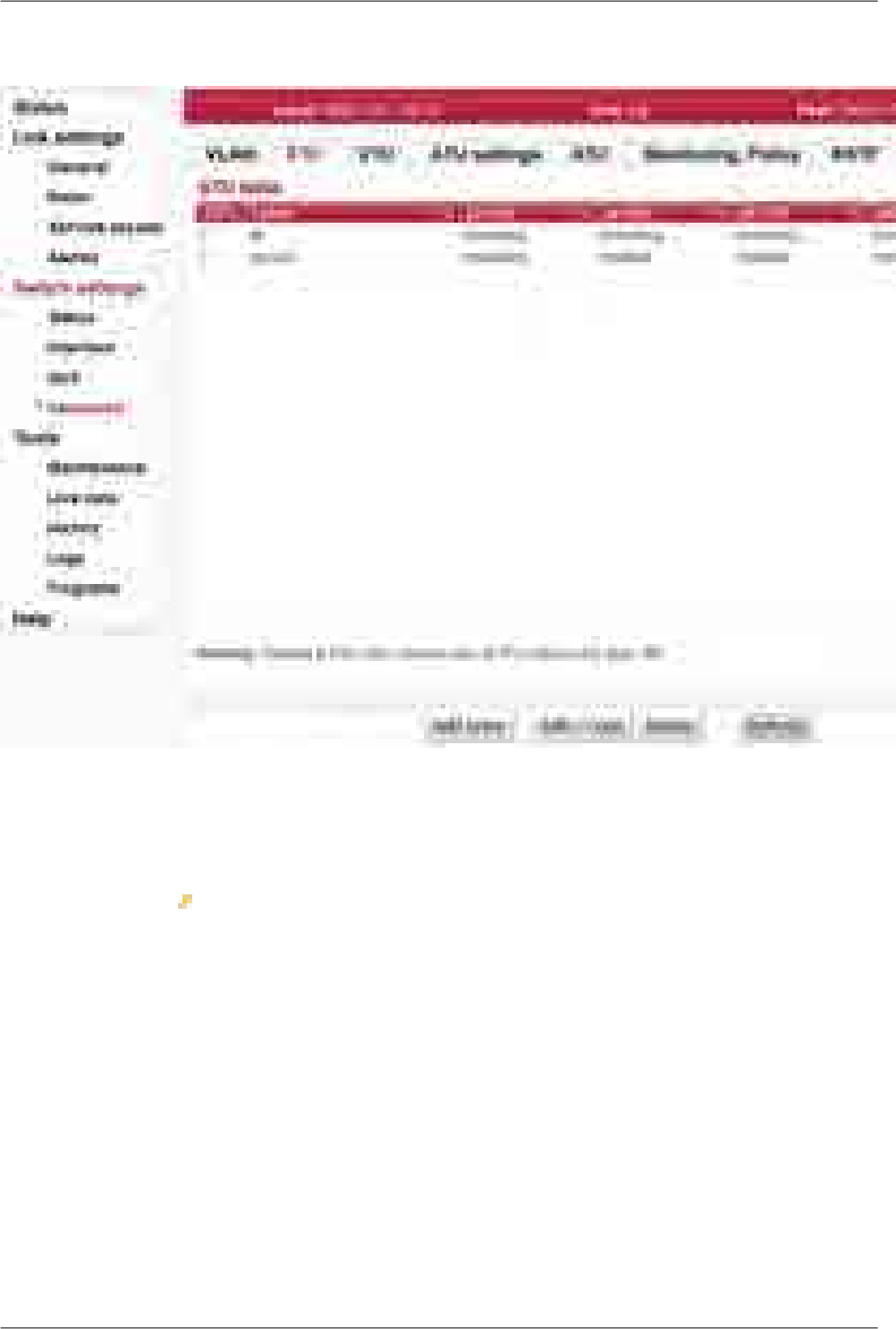
STU
Fig. 7.33: Menu Switch settings - Advanced - STU
The per VLAN Spanning Tree Unit (STU) in the device supports user commands to access and modify
the contents of the Port State database.
Primary key The icon indicates which parameter field is taken as the unique identifier in the
database. This field entry ensures each record is unique and must not be duplicated.
SID VTU 802.1s (MSTP) Port State Information Database number. This parameter indicates
the SID number that is associated with the 802.1s Port state parameter.
It is essential to define the SID to be able to create records in the VTU (VLAN Table).
Label A custom string label for a STU entry.
Port state This parameter is used to support 802.1s per VLAN spanning tree. Port states (bellow)
are valid for frames with a VID that is associated to this SID:
Use non-VLAN Port States (i.e., the port's default Port State) for this
port.
disabled
blocking
/listening
learning
123© RACOM s.r.o. – RAy2 Microwave Link
Configuration
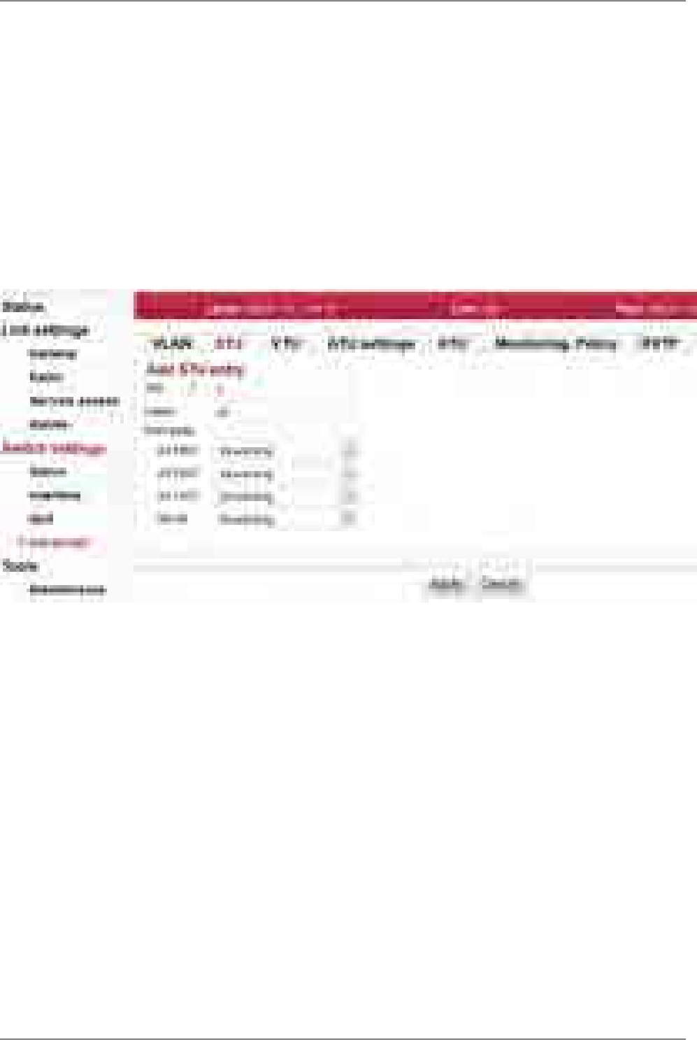
forwarding
This Port state takes precedence over the port's Port State bits unless the port's Port
State (menu Interface – Port advanced – State) is Disabled (which prevents all frames
from flowing).
Add entry Add a new STU database entry.
Edit Press the Edit button to open the configuration dialog of the selected STU database
record.
NOTE: Should the Primary key value be modified, the "other" record - identified by
the entered Primary key - is added (if it doesn't exist yet) or modified (if it exists already).
Delete Delete the selected STU database record.
Fig. 7.34: Menu Switch settings - Advanced - STU - edit
RAy2 Microwave Link – © RACOM s.r.o.124
Configuration
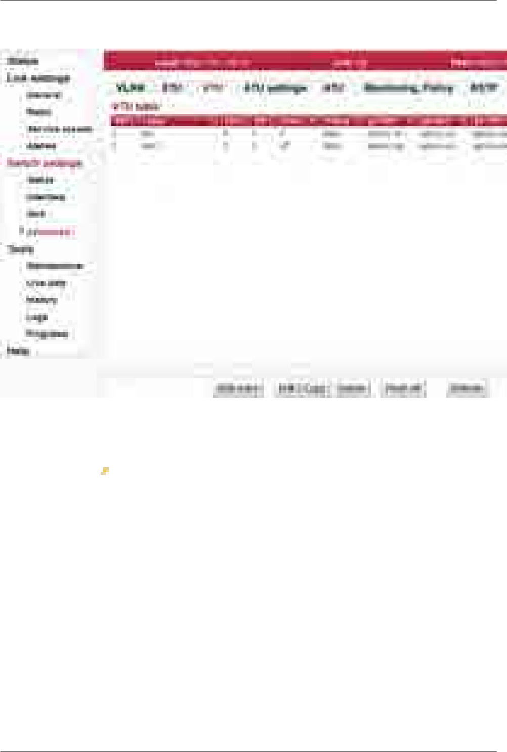
VTU
Fig. 7.35: Menu Switch settings - Advanced - VTU
The VTU (VLAN Table Unit) records form the VLAN Table.
Primary key The icon indicates which parameter field is taken as the unique identifier in the
database. This field entry ensures each record is unique and must not be duplicated.
VID VLAN ID. This parameter indicates the VID number that is associated with the Member
tag, VTU Priority, VTU policy and the FID (Forwarding Information Database number).
Label A custom string label for a VTU entry.
FID Forwarding Information Database number. If separate address databases are used,
this parameter indicates the address database number to use for all frames assigned
with this VID. All MAC DA look-ups and SA learning will refer to the address database
number defined by the FID associated with the frame's VID. Multiple VID's can use
the same FID. If separate address databases are not used, the FID must be zero. The
ATU database records are joined with the VTU database records via this number.
SID 802.1s Information Database Number. If 802.1s per VLAN spanning tree is being
used, this parameter indicate the spanning tree instance number to use for all frames
assigned with this VID. Multiple VID's can use the same SID. The STU database re-
cords are joined with the VTU database records via this number.
125© RACOM s.r.o. – RAy2 Microwave Link
Configuration

Use
VID priority VID Priority Override. This parameter is used to indicate that frames assigned with
this VID can have their priority overridden with the VID priority value (see below) if the
port's VTU priority override parameters is enabled to do so. See VTU priority override
for more details.
VID priority VID Priority override value when enabled by the Use VID priority parameter (see
above). Used for priority override on ingressing frames. Enabling a priority on a VID
will override the frame's priority only if the port's VTU priority override parameter is
enabled to do so.
VID policy This parameter is used to indicate that frames assigned with this VID can have Layer
2 Policy actions applied to it if the port's Policy VTU (menu Advanced/Monitoring,
Policy/Policy) is enabled to do so.
Member tag This parameters is used to indicate which ports are members of the VLAN (i.e, with
the given VID) and if these VLANs frames should be tagged or untagged, or unmodified
when exiting the port as follows:
Port is a member of this VLAN and frames are to egress unmodified.egress un-
modified
Port is a member of this VLAN and frames are to egress Untagged.egress un-
tagged
Port is a member of this VLAN and frames are to egress Tagged.egress
tagged
Port is not a member of this VLAN. The result is that frames assigned
with this VID can not egress this port.
not member
This parameter takes effect only if the 802.1q mode parameter (see menu Ad-
vanced/VLAN) is set to secure mode.
Add entry Add a new VTU database entry.
Edit Press the Edit button to open the configuration dialog of selected VTU database record.
NOTE: Should the Primary key value be modified, the "other" record - identified by
the entered Primary key - is added (if it doesn't exist yet) or modified (if it exists already).
Delete Delete the selected VTU database record.
Flush all Delete the whole VTU database.
RAy2 Microwave Link – © RACOM s.r.o.126
Configuration
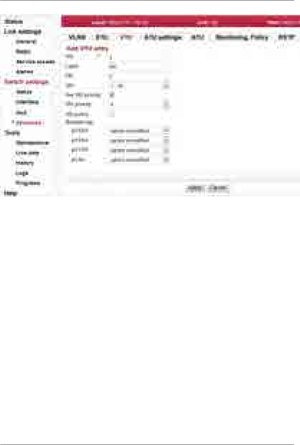
Fig. 7.36: Menu Switch settings - Advanced - VTU - edit
127© RACOM s.r.o. – RAy2 Microwave Link
Configuration
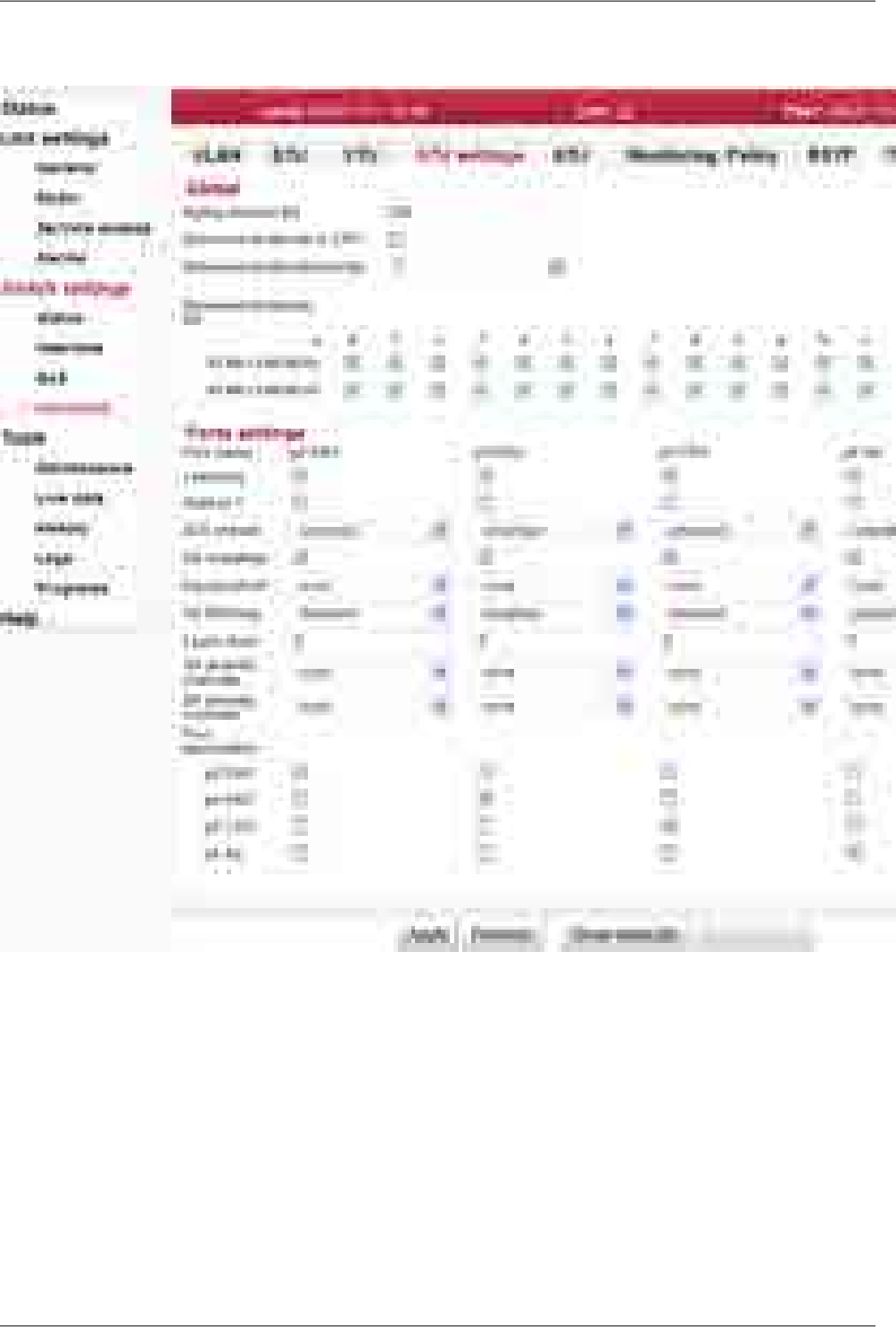
ATU settings
Fig. 7.37: Menu Switch settings - Advanced - ATU settings
Setup of ATU (Address Translation Unit) table related parameters.
Aging
timeout [s] ATU age time. This value determines the time that each ATU Entry remains valid in
the database, since its last access as a source address, before being purged.
The default value is 330 seconds.
The minimum age time is 15 seconds.
The maximum age time is 3825 seconds (almost 64 minutes).
If the Age Time is set to 0 the Aging function is disabled and all learned addresses
will remain in the database forever.
RAy2 Microwave Link – © RACOM s.r.o.128
Configuration

Reserved
multicast
to CPU
When this parameter is enabled, frames with a Destination Address in the range
01:80:C2:00:00:0x or 01:80:C2:00:00:2x, regardless of their VLAN membership, will
be considered MGMT frames and sent to the CPU port. See the "RSTP, RSTP enable"
parameter.
Reserved
multicast pri-
ority
This parameter sets the priority of the frames affected by Reserved
multicast to CPU parameter.
Reserved
multicast DA This parameter enables individual multicast DA addresses to be affected by Re-
served multicast to CPU parameter.
Port name Identification of the internal switch port. The switch ports are connected to an external
port or to an internal device (radio modem, management CPU).
The external port (with RJ45 interface) labeled "ETH1+POE". Port 2.
The external port (with SFP interface) labeled "ETH2". Port 4.
The internal port to management CPU. It is physical port number 5.
The internal port to radio modem, i.e. link to the peer unit. Port 6.
Eth1
Eth2
CPU
Air
Learning
(ForceMap) When this parameter is disabled, normal frame processing occurs.
When this parameter is enabled, all received frames will be considered MGMT (MG-
MT=Management frames, frames that can tunnel through Blocked ports) and are
mapped to the port or ports defined in the VLANTable bits overriding the mapping
from the address database. The forcing function is needed to get BPDU frames to
egress specific ports by the CPU for the Spanning Tree Protocol. ForceMapped frames
will egress ports that are not in the Disabled port state (i.e., they are MGMT frames
and will egress via Blocked ports). This parameter is accessible by the CPU's Ingress
Header so the CPU can enable and disable MGMT and forcing on a frame by frame
bases.
NOTE: Learning is disabled on MGMT frames, so enabling this parameter also
disables learning on frames entering this port.
Hold at 1 Hold Aging ATU Entries at an Entry State value of 1. When this parameter is disabled,
a zero normal Aging occurs for ATU entries associated with this port. When this
parameter is enabled ATU entries associated with this port will age down to an Entry
state of 1 but will not go to 0. This feature can be used (for example) to keep dynamic
records in the ATU table.
ATU refresh Normal address learning is enabledunlocked
Auto refreshing of known addresses will occur even if this port is
Locked. Already known addresses will be auto refreshed (i.e., their
known
Entry State will be updated to 0x7 whenever this address is used as
a source address in a frame on this port) even when this port is
Locked.
CPU directed learning (needed for 802.1X MAC authentication) is
enabled. Automatic SA learning and refreshing is disabled in this
mode.
locked
DA mapping When this parameter is enabled, normal switch operation occurs where a frame's DA
is used to direct the frame out of the correct port. When this parameter is disabled the
frame will be sent out of the port defined by EgressFloods even if the DA is found in
the address database. The static ATU table records are used, even in DA mapping
disabled status.
129© RACOM s.r.o. – RAy2 Microwave Link
Configuration

Egress block Egress Flooding mode. The DA of every unicast and multicast frame is searched in
the ATU. If the DA is found in the address database it is considered known. If it is not
found it is considered unknown. Frames with known DA's are not affected by this re-
gister.
Frames with unknown DA's generally flood out all the ports (except the port they ori-
ginally came in on). This register can be used to prevent frames with unknown DA's
from egressing this port as follows:
Do not egress any frame with an unknown DA (unicast or multicast)unknown
Do not egress any frame with an unknown multicast DAunknown
multicast
Do not egress any frame with an unknown unicast DAunknown
unicast
Egress all frames with an unknown DA (unicast and multicast)none
SA filtering Source Address Filtering method:
No frame will be filtered (i.e. discarded) as a result of the contents
of its Source Address field.
disabled
Ingressing frames will be discarded if their SA field is not in the ATU's
address database (i.e. it's a new or unknown Source Address) or if
drop
on lock this port's bit is not set in the PortVec bits for the frames' SA (i.e. this
port is not the source port for that MAC address). Used for MAC
based 802.1X.
Ingressing frames will be discarded if their SA field is in the ATU's
address database as a Static entry with a PortVec of all zeros. Used
to discard frames from known untrusted sources.
drop
on unlock
Ingressing frames will be mapped to the CPUDest if their SA field is
in the ATU's address database as a Static entry with a PortVec of
drop
to CPU all zeros and the frame is not otherwise filtered. Otherwise, the frames
will be discarded if their SA field is not in the ATU's address database
(i.e. it's a new or unknown Source Address) or if this port's bit is not
set in the PortVec bits for the frames' SA (i.e. this port is not the
source port for that MAC address). This mode is a form of MAC based
802.1X where some frames can be forced to the CPU for further
authentication prior to full authorization.
Learn limit
(LearnLimit) When this parameter is set to zero, normal address learning and frame policy occurs.
When this parameter is non-zero the number of MAC addresses that can be learned
on this port are limited to the value of this parameter. Automatic learning and frame
policy will occur normally until the number of unicast MAC addresses auto-learned
from this port reaches the port's LearnLimit (addresses that were learned from this
port but were aged out are not counted - i.e., this register limits the number of 'active'
unicast MAC addresses associated to this port). When the LearnLimit has been reached
any frame that ingresses this port with a source MAC address not already in the ad-
dress database that is associated with this port will be discarded (the port will act as
if the port is Locked and the port's DropOnLock SAFiltering mode is set). Normal auto-
learning will resume on the port as soon as the number of 'active' unicast MAC ad-
dresses associated to this port is less than the LearnLimit (due to address aging).
Care is needed when enabling this feature:
Enable "Learn to all" (GL1-0x0A:11:3 Learn2All=1)
RAy2 Microwave Link – © RACOM s.r.o.130
Configuration

Set SA filtering to disabled or drop on unlock (PORT-0x04:14 SAFiltering[0]=0)
Safe procedure:
Disable or block the ports (PORT-04.1 PortState[1]=0).
Flush all non-static adresses in the ATU.
Define the desired limit for the ports.
Re-enable the ports.
SA priority
override When any other than "none" mode is selected, SA ATU priority overrides can occur
on this port. An SA ATU priority override occurs when the source address of a frame
results in an ATU hit where the SA's MAC address returns an EntryState that indicates
Priority Override. When this happens three forms of priority overrides are possible
(other than none):
Normal frame priority processing is active.none
PRI value assigned to the frame's SA (the MAC priority field in the
ATU database) is used to overwrite the frame's previously determined
frame
frame priority (FPri). If the frame egresses, the tagged priority in the
frame will be this new PRI value.
The two upper bits of the PRI value assigned to the frame's SA (the
MAC priority field in the ATU database) are used to overwrite the
queue
frame's previously determined queue priority (QPri). The QPri is used
internally to map the frame to one of the egress queues inside the
switch. QPri override will not affect the contents of the frame in any
way.
Both above overrides take effect on the frameframe+queue
The SA ATU Priority Override has a higher priority than the port's Default Priority, the
frame's IEEE and/or IP priorities and the VTU Priority Override. The priority determined
by the frame's SA can however be overridden, by the frame's DA Priority Override.
DA priority
override When any other than none mode is selected, the DA ATU priority overrides can occur
on this port. A DA ATU priority override occurs when the source address of a frame
results in an ATU hit where the DA's MAC address returns an EntryState that indicates
Priority Override. When this occurs three forms of priority overrides are possible
(other than none):
Normal frame priority processing is active.none
PRI value assigned to the frame's DA (the MAC priority field in the
ATU database) is used to overwrite the frame's previously determined
frame
frame priority (FPri). If the frame egresses the tagged priority in the
frame will be the new PRI value.
The two upper bits of the PRI value assigned to the frame's DA (the
MAC priority field in the ATU database) are used to overwrite the
queue
frame's previously determined queue priority (QPri). The QPri is used
internally to map the frame to one of the egress queues inside the
switch. QPri override will not affect the contents of the frame in any
way.
Both of the above overrides take place on the frameframe+queue
The DA ATU Priority Override has the highest priority over the port's Default Priority,
the frame's IEEE and/or IP priorities, the VTU Priority Override and the SA Priority
Override.
131© RACOM s.r.o. – RAy2 Microwave Link
Configuration

Port
association
(PAV)
Port Association Vector for ATU learning. The value in these bits (one bit per port) is
used as the port's DPV on automatic ATU Learning or Entry_State refresh whenever
these bits contain a non-zero value. When these bits are all zero, automatic Learning
and Entry_State refresh is disabled on this port.
For normal switch operation, this port's bit should be the only bit set in the vector.
These bits must only be changed when frames are not entering the port.
The PAV bits can be used to set up port trunking (along with the VLANTable bits). For
the two ports that form a trunk, set both of their port's bits in both port's PAV registers
(this Port association parameter for both ports of the trunk), then use the VLANTable
to isolate the two ports from each other, or to use the Trunk Mask table to steer the
traffic from the other ports down the desired trunk line of the pair using DA/SA Load
Balancing.
RAy2 Microwave Link – © RACOM s.r.o.132
Configuration
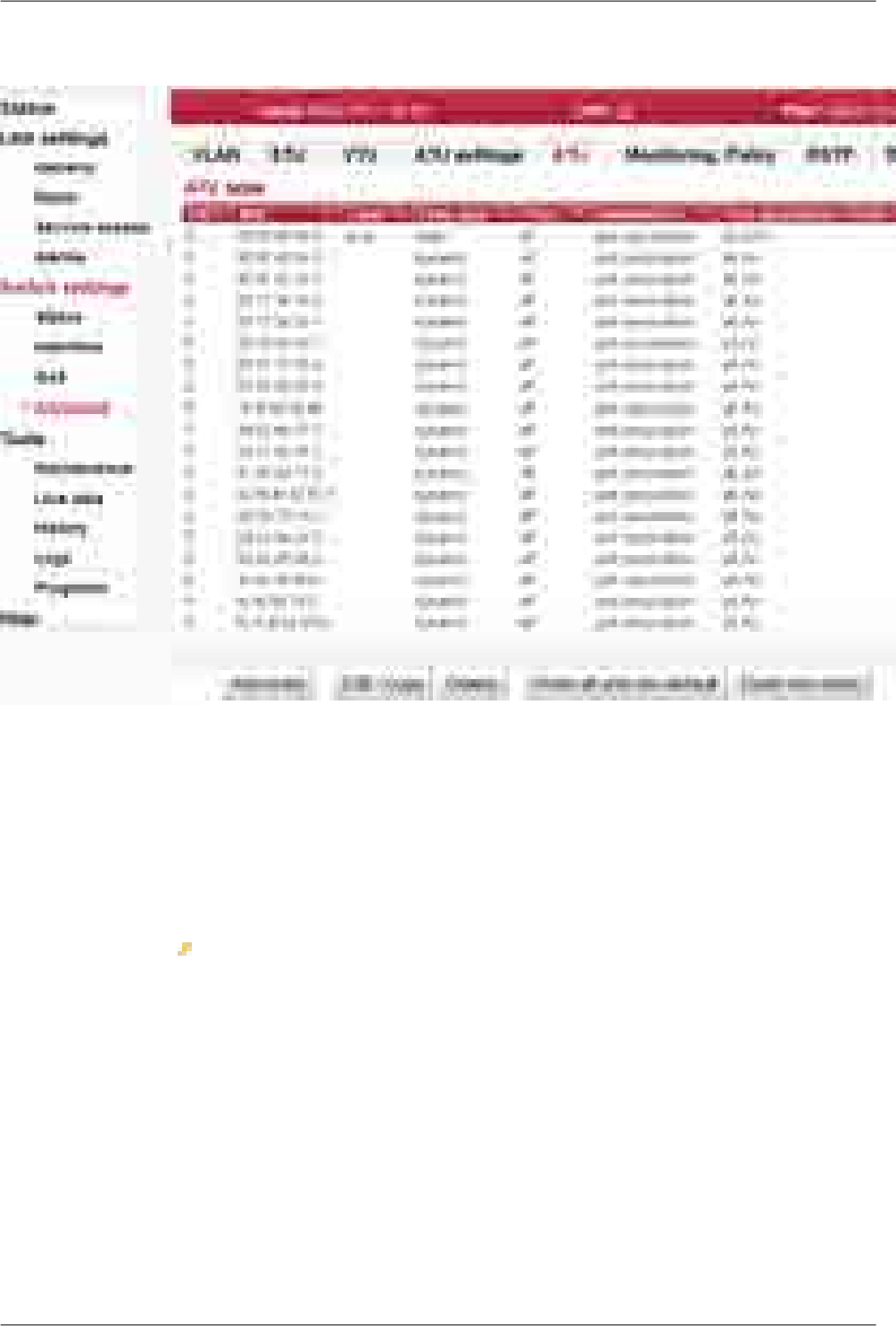
ATU
Fig. 7.38: Menu Switch settings - Advanced - ATU
The Address Translation Unit (ATU) in the device supports user commands to access the contents of
the MAC address database.
There is one static record which can't be deleted. This is the management CPU record. The unicast
frames directed to management are allowed to access the CPU port. The VLAN tunnel parameter is
also used to enable the AP frames to access the CPU port.
Primary key The icon indicates which parameter field is taken as the unique identifier in the
database. This field entry ensures each record is unique and must not be duplicated.
FID Forwarding Information Database number. If multiple address databases are not being
used, this parameter must remain zero. If multiple address databases are being used,
this parameter is used to set the desired address database number that is to be asso-
ciated with this ATU Entry's MAC Address. When frames ingress the switch, the VID
assigned to the frame is used to access the VTU. The VTU returns the FID associated
with that VID for MAC address lookups in to the ATU.
MAC MAC address associated with this ATU entry in the database number defined by the
FID.
Label A custom string label for an ATU entry.
Entry state The Entry state parameter is used to determine the entry's age or its type as follows:
133© RACOM s.r.o. – RAy2 Microwave Link
Configuration

Use for ordinary static entry.static
Use for Policy DA and/or Policy SA (menu Switch settings – Advanced
– Monitoring – Policy).
static policy
Use for SA non rate limit and/or DA non rate limit (menu Switch set-
tings – Interface – PIRL).
static non
rate limiting
This value is used for the mapping of the DA even if the DA mapping
parameter is disabled (menu Switch settings – Advanced – ATU
settings).
static man-
agement
Ordinary dynamic entry.dynamic
Use
MAC priority Use this parameter to enable the MAC priority (see MAC priority description).
MAC priority The MAC's Priority override value when enabled by the Use MAC priority parameter.
Used for priority override on ingressing frames. Enabling a priority on a MGMT MAC
address will override all priorities for these MGMT frames. Enabling a priority on a
static, non-MGMT MAC address, will only override the frame's priority if the port's DA
priority override or SA priority override parameters are enabled.
Trunk
member When this parameter is enabled, the MAC address is a member of a trunk - according
to the Trunk Id parameter. When this parameter is disabled, the MAC address is as-
sociated with port(s) - according to the Port association parameter.
Trunk Id The Trunk ID associated with this MAC address.
The port or ports that this DA MAC address is associated with is determined by the
Port association parameter below.
Use this parameter to ensure the proper unit management CPU is accessed when
two units are connected in trunk.
Trunk port
assotiation
vector
Mask of ports associated with this MAC address.
Add entry Add a new ATU database entry.
Edit/Copy Press the Edit/Copy button to open the configuration dialog of the selected ATU
database record.
NOTE: Should the Primary key value be modified, the "other" record - identified by
the entered Primary key - is added (if it doesn't exist yet) or modified (if it exists already).
Delete Delete the selected ATU database record.
Flush all and
use default Delete the whole ATU database and create default record(s).
Flush
non-static Delete all except static ATU database records.
RAy2 Microwave Link – © RACOM s.r.o.134
Configuration
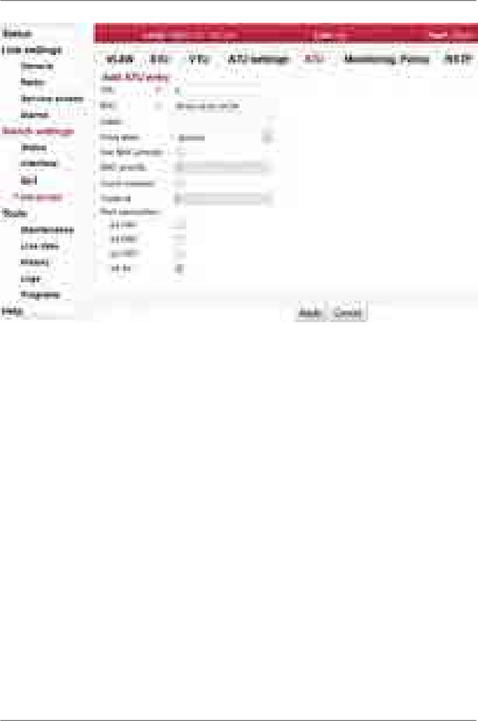
Fig. 7.39: Menu Switch settings - Advanced - ATU - edit
135© RACOM s.r.o. – RAy2 Microwave Link
Configuration
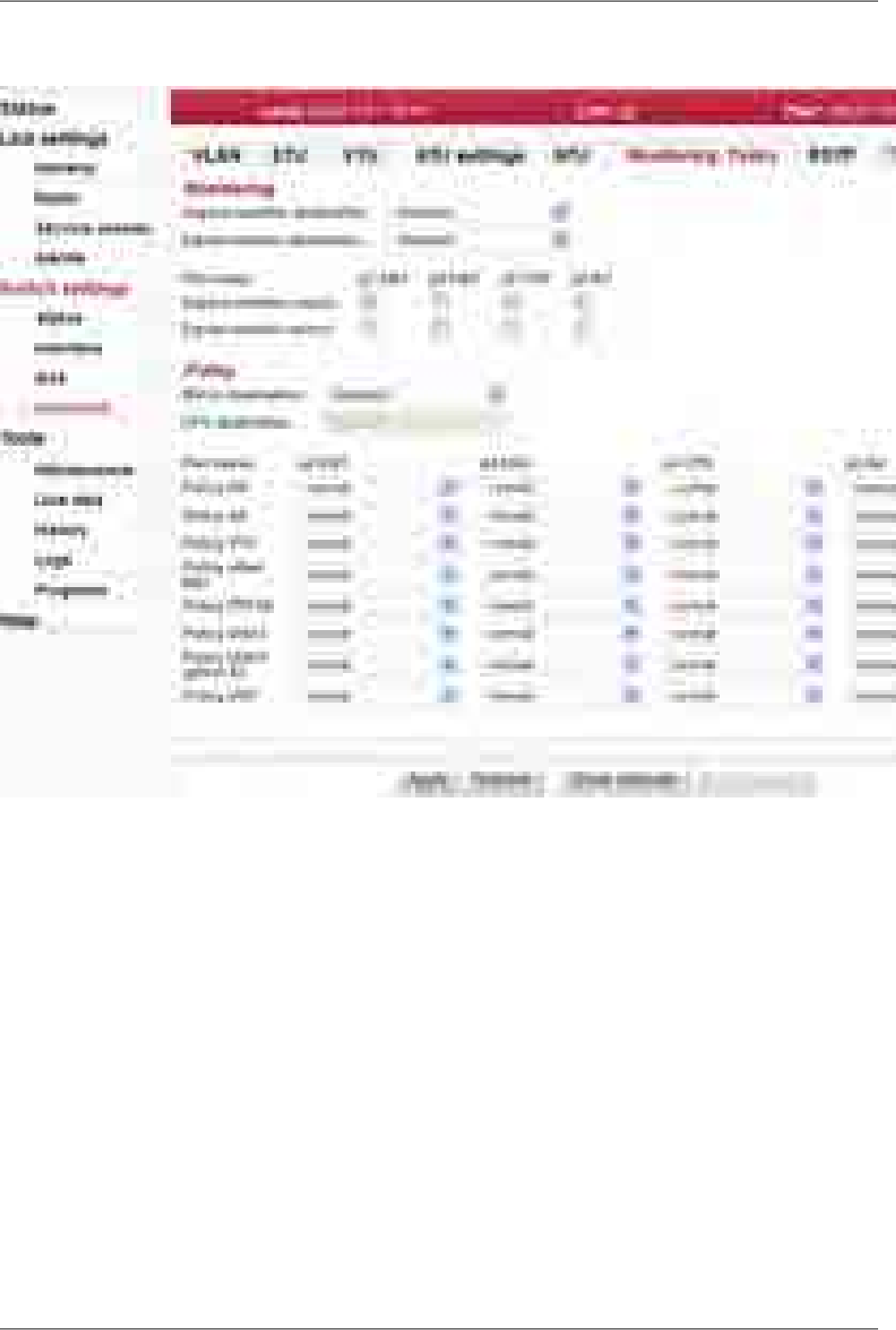
Monitoring, Policy
Fig. 7.40: Menu Switch settings - Advanced - Monitoring, Policy
Setup of Monitoring and Policy functions.
The Policy functions allow for special handling of specific types of ingress frames.
Ingress
monitor
destination
Frames that are targeted toward an Ingress Monitor Destination leave via the port
selected by this parameter. This includes frames received on a port that is enabled
to be the Ingress monitor source.
Egress
monitor
destination
Frames that are targeted toward an Egress Monitor Destination leave via the port se-
lected by this parameter. This includes frames transmitted on a port that is enabled
to be the Egress monitor source.
Port name Identification of the internal switch port. The switch ports are connected to an external
port or to an internal device (radio modem, management CPU).
The external port (with RJ45 interface) labeled "ETH1+POE". Port 2.
The external port (with SFP interface) labeled "ETH2". Port 4.
The internal port to management CPU. It is physical port number 5.
The internal port to radio modem, i.e. link to the peer unit. Port 6.
Eth1
Eth2
CPU
Air
RAy2 Microwave Link – © RACOM s.r.o.136
Configuration

Ingress
monitor
source
When this parameter is enabled, any frame that ingresses this port is also sent to the
Ingress monitor destination port. The frame is sent to this port even if it is discarded
due to switching policy but the frame will not be forwarded if it contains an error (such
as CRC, etc.) or is filtered by ingress rate limiting.
Egress
monitor
source
When this parameter is enabled any frame that egresses this port will also be sent to
the Egress monitor destination port. The 802.1q mode and VTU entries on the Egress
monitor destination port must be set to be the same as they are on the Egress monitor
source port so the frames egress with the same tagged or untagged information.
Mirror
destination Frames that ingress a port that trigger a policy mirror are mapped (copied) to this port
as long as the frame is not filtered or discarded.
CPU
destination CPU destination port can not be changed. It is shown here to better understand the
description of some other parameters which interact with the CPU destination port.
For example the trap value of the Policy* parameters cause frames to be forwarded
to this CPU destination port.
Policy There are four different operations as a result of a policy:
Normal frame switching.normal
Mirror (copy) frame to the Mirror destination port.
mirror
Trap (re-direct) frame to the CPU destination port.
trap
Discard (filter) the frame.discard
There are eight different policy triggers:
DA Policy Mapping occurs when the DA of a frame is contained in
the ATU address database with an Entry State set to static policy.
DA
SA Policy Mapping occurs when the SA of a frame is contained in
the ATU address database with an Entry State set to static policy.
SA
VTU Policy Mapping occurs when the VID of a frame is contained in
the VTU database with the VID policy parameter enabled.
VTU
EtherType Policy Mapping occurs when the Ether Type of a frame
matches the Ether type parameter of this port.
ether type
PPPoE Policy Mapping occurs when the Ether Type of a frame
matches 0x8863.
PPPoE
VBAS Policy Mapping occurs when the Ether Type of a frame
matches 0x8200.
VBAS
DHCP option 82 Policy Mapping occurs when the ingressing frame
is an IPv4 UDP with a UDP Destination port=0x0223of 0x0222.
DHCP
option 82
UDP Policy Mapping occurs when the ingressing frame is a Broadcast
IPv4 UDP or a Multicast IPv6 UDP.
UDP
137© RACOM s.r.o. – RAy2 Microwave Link
Configuration
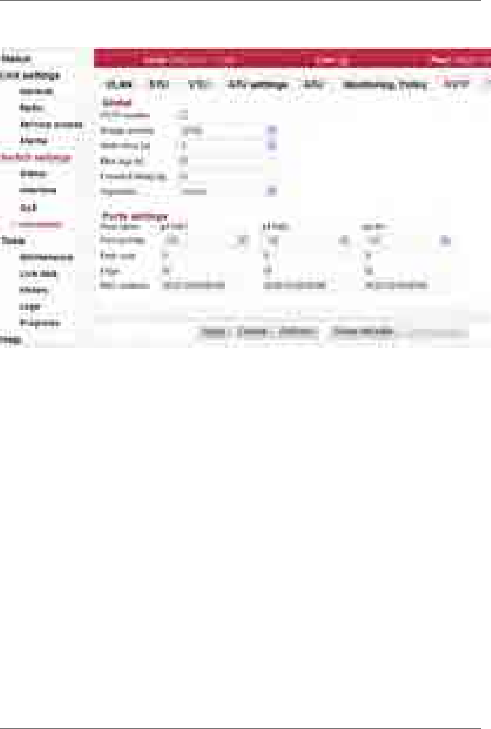
RSTP
Fig. 7.41: Menu Switch settings - Advanced - RSTP
The Rapid Spanning Tree Protocol (RSTP) is a network protocol that ensures a loop-free topology for
any bridged Ethernet local area network. The basic function of RSTP is to prevent bridge loops and
the broadcast radiation that results from them. Spanning Tree Protocol also allows network design to
include spare (redundant) links to provide automatic backup paths if an active link fails, without the
danger of bridge loops, or the need for manual enabling/disabling of these backup links.
RSTP enable When RSTP is enabled, the bridge is created and RSTP service is initiated. Should
the RAy2 unit be connected via two Etherent cables (using Eth1 and Eth2 ports), the
active participation of the RSTP protocol may be necessary. If the parameter is not
enabled, the RAy2 unit transfers the BPDU frames transparently.
NOTE: To enable proper RSTP functionality, these switch parameters has to be set:
Switch settings / Interface / Port advanced / Frame mode / p5 CPU: "ether type
DSA"
Switch settings / Interface / Port advanced / Ether type / p5 CPU: "0xDADA"
Switch settings / Advanced / ATU settings / Reserved multicast to CPU: "Enable"
Bridge
priority The priority value is a number between 0 and 61440 in incremental steps of 4096,
with a default value of 32768. Lower priority values are 'better'. The bridge with the
lowest priority value will be elected 'root bridge'.
Hello time [s] The hello time is the time between each Bridge Protocol Data Unit (BPDU) that is sent
on a port. Hello time is equal to 2 seconds by default.
RAy2 Microwave Link – © RACOM s.r.o.138
Configuration

Max age [s] The max age timer controls the maximum length of time that passes before a bridge
port saves its configuration BPDU information. This time is set to 20 sec by default.
Forward
delay [s] The forward delay is the time that is spent in the listening and learning state. This time
is equal to 15 sec by default.
Algorithm This parameter sets the bridge's spanning tree algorithm to operate in normal (RSTP)
or force it to operate in slow (STP) mode. In normal mode, RSTP reverts back to STP
on ports where it sees other hosts operating in STP mode.
Port name Identification of the internal switch port. The switch ports are connected to an external
port or to an internal device (radio modem, management CPU).
The external port (with RJ45 interface) labeled "ETH1+POE". Port 2.
The external port (with SFP interface) labeled "ETH2". Port 4.
The internal port to management CPU. It is physical port number 5.
The internal port to radio modem, i.e. link to the peer unit. Port 6.
Eth1
Eth2
CPU
Air
Port priority The ports' priority value is a number between 0 and 240 in increments of 16, with a
default value of 128.
Path cost The Path cost can be set automatically or manually. Entering the value of zero sets
this parameter automatically. The automatic setup is based on link speed.
Edge Selecting the checkbox sets the port as an "edge" port. If a port is an edge port it is
assumed to be a leaf link in the graph, not connected to any other bridges. Receiving
any STP BPDU's on a port configured as an edge port temporarily overrides edge
port behaviour for the port.
MAC address The ports' default MAC addresses are the same as the MAC address of the RAy2
unit.
139© RACOM s.r.o. – RAy2 Microwave Link
Configuration
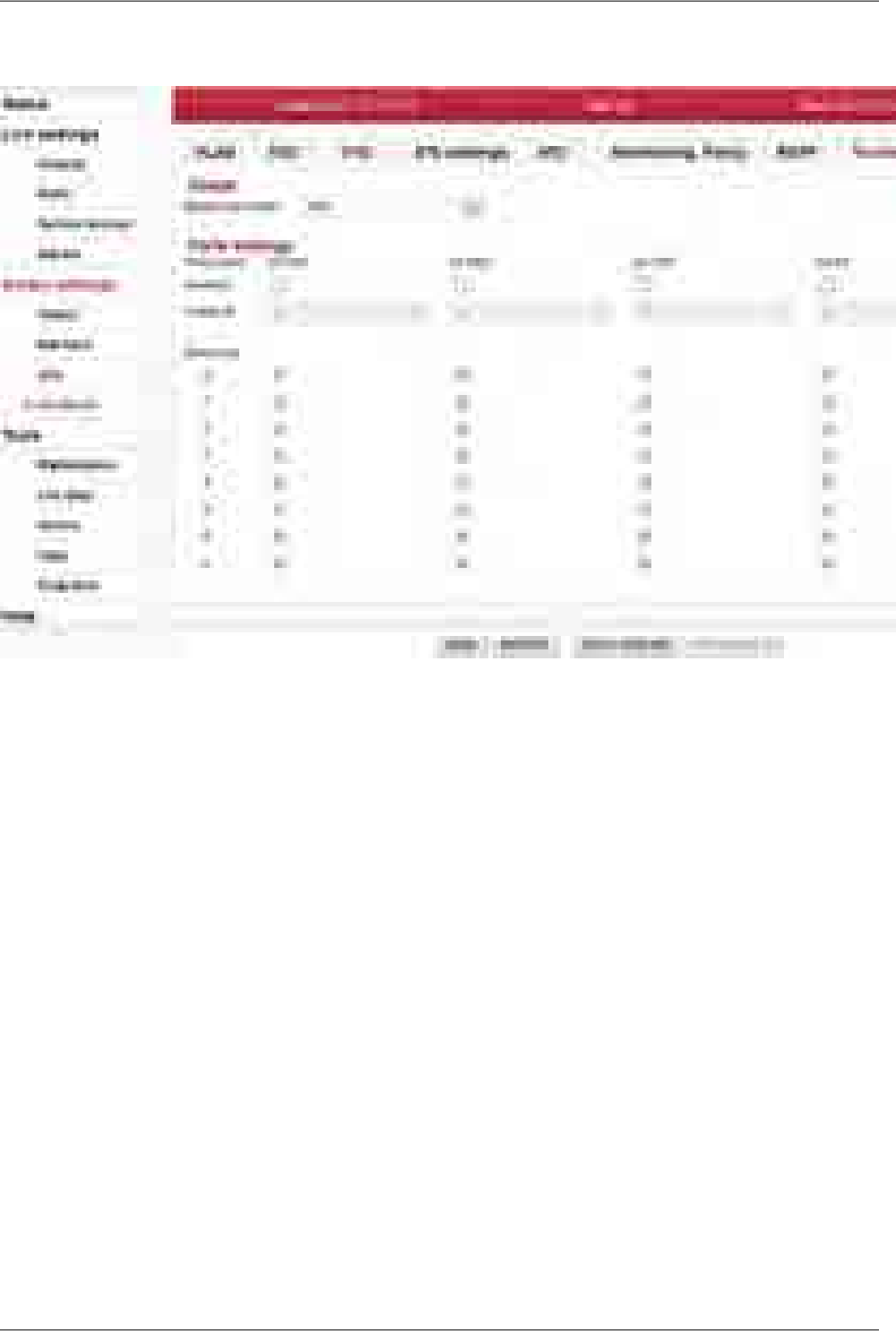
Trunk
Fig. 7.42: Menu Switch settings - Advanced - Trunk
Port trunking is supported by the device using any combinations of ports. The ports that are to be as-
sociated with the trunk need to have all the port members' defined with the same Trunk Id and the
Enabled parameter has to be enabled.
When a frame enters a Trunk Port its Source Address (SA) is learned with its association to the ingress
port's TrunkID number. In this way the contents of the address database contain the same association
with the frame's SA regardless of the link of the trunk the frame entered the switch.
When frames are routed back toward a trunk the frame will have its Destination Address (DA) found
from the address database. If the frame's DA is unknown the frame will try to flood out all ports of the
trunk (this is OK in so far as this will be fixed with load balancing). If the frame's DA is found, the entry
will indicate mapping to a trunk and the entry's DPV bits will contain the TrunkID associated with this
frame's DA. This TrunkID needs to be converted into a DPV (Destination Port Vector) that the rest of
the switch can use. This is accomplished by accessing the Trunk Mapping table using the TrunkID that
was in the ATU's entry.
Balancing
mode Hash DA and SA for TrunkMask selection. Trunk load balancing is accomplished using
the frame's DA and SA fields to access one of eight Trunk Masks. Two options are
available:
The lower 3 bits if the frame's DA and SA are XOR'ed together to
select the TrunkMask to use.
XOR
RAy2 Microwave Link – © RACOM s.r.o.140
Configuration

The hash computed for address table lookups is used for the Trunk-
Mask selection. Use this parameter to reach better load balancing
between the ports in the trunk.
hash
Port name Identification of the internal switch port. The switch ports are connected to an external
port or to an internal device (radio modem, management CPU).
The external port (with RJ45 interface) labeled "ETH1+POE". Port 2.
The external port (with SFP interface) labeled "ETH2". Port 4.
The internal port to management CPU. It is physical port number 5.
The internal port to radio modem, i.e. link to the peer unit. Port 6.
Eth1
Eth2
CPU
Air
Enabled When this parameter is enabled, the port is considered to be a member of a trunk with
the Trunk Id defined below.
Trunk Id This parameter defines which trunk the port is to be associated with. All ports that are
members of the same trunk must be assigned the same Trunk ID.
Balancing Trunk Mask bits.
141© RACOM s.r.o. – RAy2 Microwave Link
Configuration
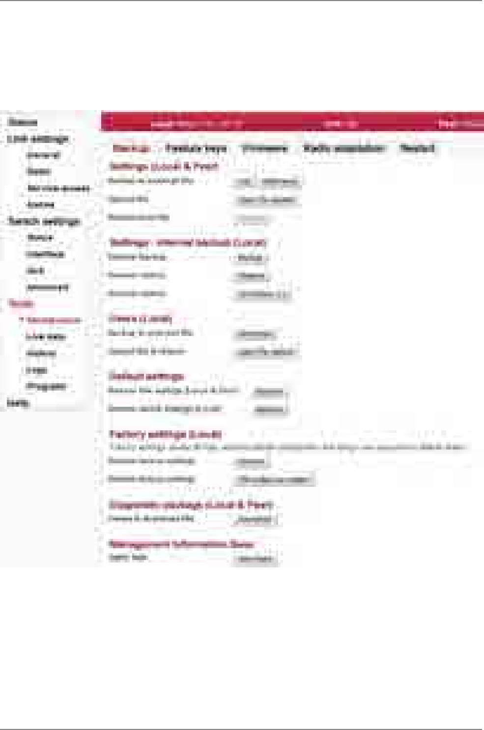
7.6. Tools
7.6.1. Maintenance
Backup
Fig. 7.43: Menu Tools - Backup
Saving and restoring unit configuration. User accounts are not affected by those
functions.
Settings
(Local & Peer)
RAy2 Microwave Link – © RACOM s.r.o.142
Configuration
Configuration is saved to backup file which is downloaded to
management PC. The backup file name contains the date,
time and RAy serial number as follows:
yyyyMMddhhmm_SN_cnf_backup.tgz.
It can be either a full configuration or a difference to the de-
fault configuration.
Backup
to external file
Local Peer
Link
Switch
Users
Upload configuration from a backup file into buffer. The cur-
rent unit configuration is not affected. The uploaded configur-
Upload file
ation can be displayed using Show backup button on partic-
ular configuration screens. The configuration of the entire
unit can be restored (from this buffer) using Restore button
below.
After the configuration backup file has been loaded into the
unit buffer (using Upload button above), the whole unit con-
figuration can be restored using Restore button.
Restore from file
It is possible to make a temporary backup of the unit configuration. The backup is
stored directly in the unit FLASH memory.
Settings -
Internal backup
(Local) NOTE: The internal backup is deleted if factory settings or
firmware upgrade are performed.
L P
L
S
U
Make a temporary backup of the unit configuration locally in
the unit FLASH memory.
Internal backup
Restore (from the unit FLASH memory) the temporary backup
of the unit configuration.
Internal restore
The local temporary backup of the unit configuration can be
restored using the hardware button. The HW button is located
next to the DC connector within the port marked "P".
The rollback and reboot functions are suppressed while
restoring from internal backup. All changes are applied imme-
Internal restore
- HW button
diately. Should the time zone be changed, the unit has to be
restarted for changes to take effect.
Press the HW button for the required time interval of 5
seconds. The button being pressed is confirmed by the Status
LED flashing green. After the 5 seconds guard time, the unit
restores to customer settings.
Saving and restoring user accounts.Users (Local)
Backup local unit user accounts to an external file. The file
is downloaded to management PC.
NOTE: The "super" user privileges are necessary to be able
to perform this action.
Backup
to external file
L P
L
S
U
Restoring user accounts from an external backup file.Upload file
& restore
Applying default values to configuration parameters.Default settings
143© RACOM s.r.o. – RAy2 Microwave Link
Configuration
Whole set of parameters from the Link settings menu tree is
affected.
Restore link
settings
(Local & Peer)
L P
L
S
U
Whole set of parameters from the Switch settings menu tree
is affected.
Restore switch
settings (Local)
L P
L
S
U
WARNING: Using the factory settings function will revert the
unit to its original state. All configuration items, user accounts,
Factory set-
tings (Local)
measured values and system messages (logs) will be irre-
versibly deleted.
WARNING: This task takes a few minutes to complete. Do
not interrupt the power supply during the operation.
L P
L
S
U
Applying Factory settings to Local unit. The unit reboots itself
after applying all changes.
Restore
factory settings
It is possible to bring the unit to Factory settings by holding
the hardware button depressed during unit's boot. The HW
Restore
factory settings
- HW button button is located next to the DC connector within the port
marked "P".
Disconnect the power supply from the unit. Keep the HW
button depressed while reconnecting the power. The LED
marked SYS starts to flash red after a few seconds. Keep
the HW button pressed another 5 seconds until the red status
LED stops flashing. The unit's boot up sequence continues
and Factory settings are applied.
Should the HW button be released when the status LED is
in the red flashing phase (but before the 5 s guard time), the
unit stays in Service mode. Please, leave this mode by re-
booting the unit.
To facilitate communication with the technical support you can create an archive file
with detailed information about the unit. If connection with Peer unit is active the
diagnostic information from both units are saved.
Diagnostic
package
(Local & Peer)
Saving a file with information about the unit (Local and Peer).Create
& download file
NOTE: This task takes a few minutes to complete.
Provides Management Information Base table.SNMP MIBManagement
Information
Base
RAy2 Microwave Link – © RACOM s.r.o.144
Configuration
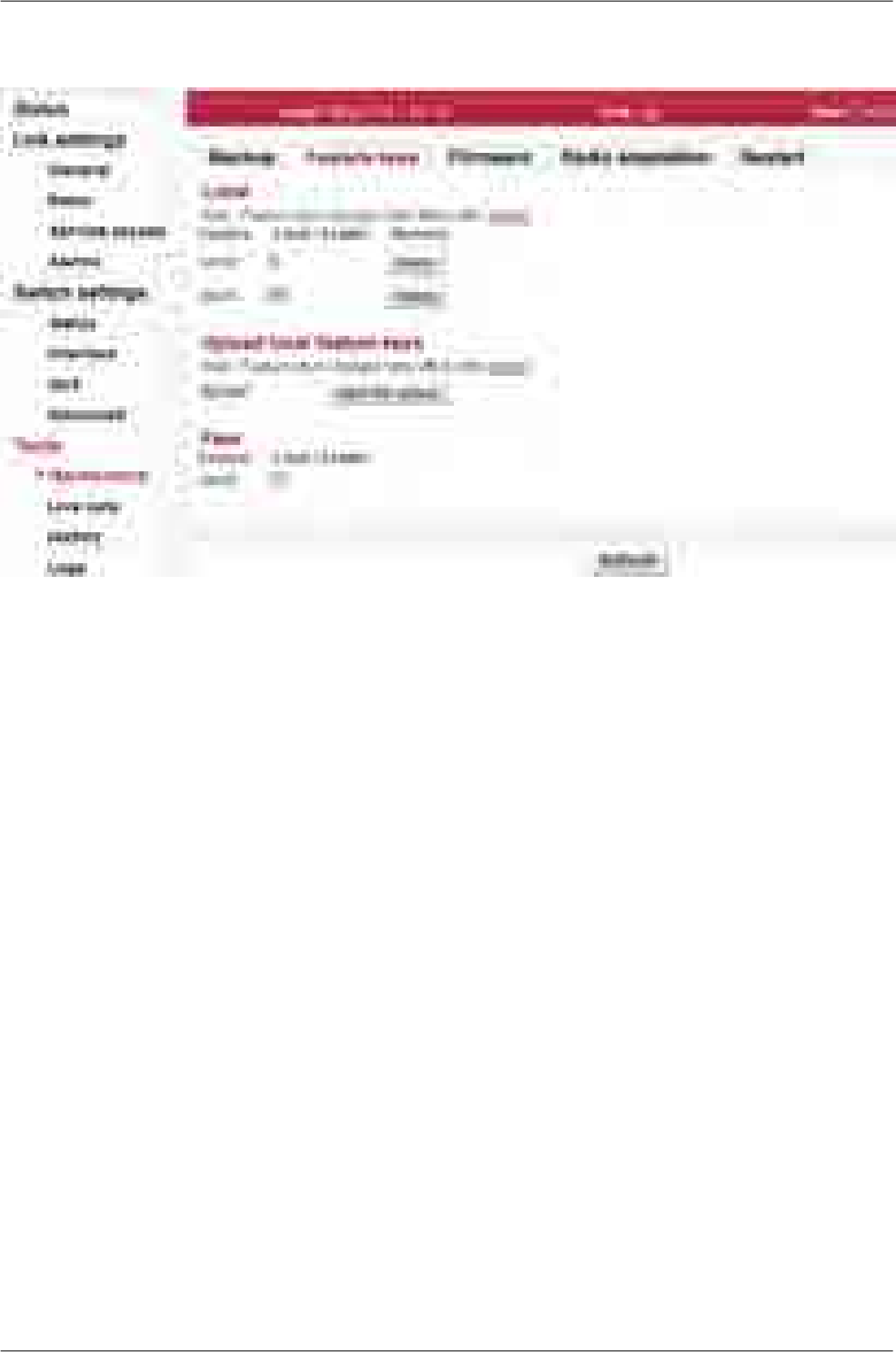
Feature keys
Fig. 7.44: Menu Tools - Feature keys
The sub-set of RAy parameters is affected by use of Feature keys.
The feature keys limiting data transfer speed [Mbps] are now available. Speed of the transferred data
is determined by a combination of the radio channel bandwidth (parameter Bandwidth [MHz]) and
modulation order (parameter TX modulation). The Feature key limiting the data transfer speed enables
only certain combinations of the channel bandwidth and modulation order to get the data transfer speed
according to the Feature key. The data transfer speed is typically slightly higher than declared.
When installed, the Feature key is activated after the unit restart. The unit can be restarted using the
Tools – Maintenance – Restart. Choose the Restart mode – warm.
Feature Name of the function controlled by the Feature key.
Here are listed the keys used in both units. Feature keys of the Peer unit only, are
displayed. They can be neither added, nor deleted. To be able to manipulate the
Feature keys, it is necessary to access directly the management system of the
relevant unit - use the IP address of the relevant unit.
Limit The numeric value set by the key.
Remove The specific Feature key can be deleted using the Delete button. The parameters
controlled by this Feature key are reset to their default values after the unit restart.
NOTE: The link radio parameters can be changed subsequently (e.g. to a different
operating frequency)!
Upload Feature keys are installed into the unit from the binary files.
NOTE: Use the file as it is (do not unpack).
Open file upload - Dialog for the Feature key binary file selection is open.
145© RACOM s.r.o. – RAy2 Microwave Link
Configuration
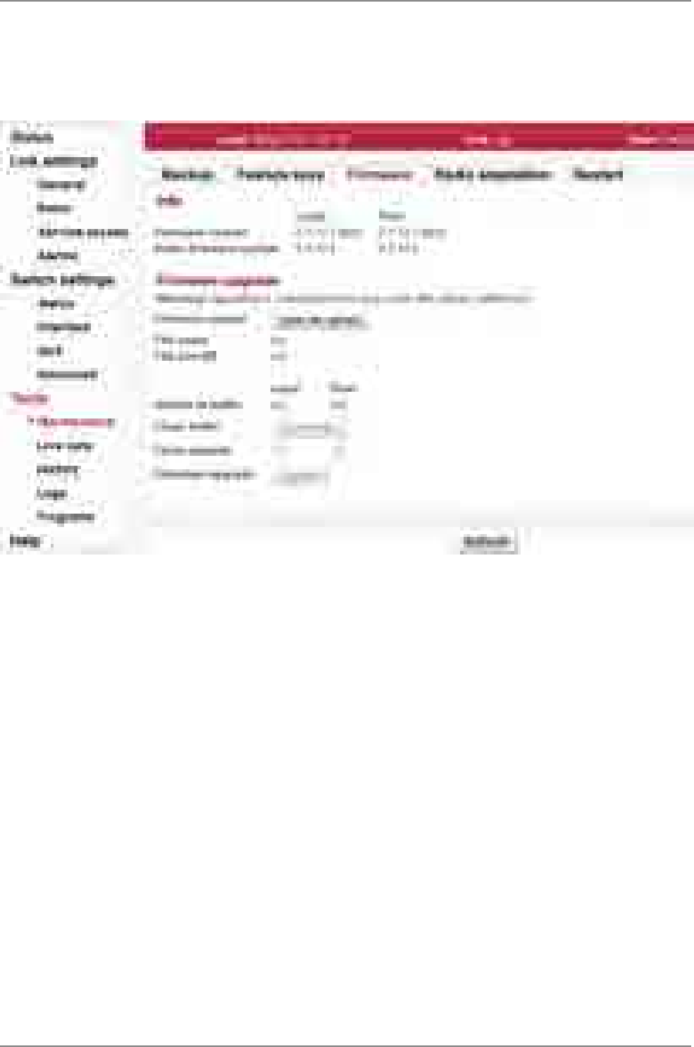
The Feature key is activated after the unit restart.
Firmware
Fig. 7.45: Menu Tools - Firmware
If a new firmware version is released for the given microwave link type, you can upload it to your RAy
units.
Info
Firmware
version Information about the current firmware package version on Local and Peer unit.
Radio firmware
version Information about the radio board current firmware version on Local and Peer unit.
Radio configura-
tion version Radio board calibration data format version.
Hardware
version Information about the HW version of the modem board.
Radio hardware
version Information about the HW version of the radio board.
Firmware upgrade
RAy2 Microwave Link – © RACOM s.r.o.146
Configuration

Firmware upload Open file upload - opens a dialog for uploading firmware package to the unit buffer.
Only after firmware has been prepared in the buffer, can you perform the actual
upgrade.
NOTE: Use the file as it is (do not unpack).
File name Name of the uploaded firmware file.
File size [B] Size of the uploaded firmware file.
Version in buffer Information about firmware version prepared in the buffer for installation into the
unit (Local, Peer). This firmware must first be prepared in the Firmware upload
section (see above).
Clean buffer You can use the Clean buffer button to delete prepared firmware package in the
buffer.
Force upgrade Force mode blocks all safety and compatibility checks and probably bricks your
unit.
You should not use force mode until instructed to do so by the technical support.
Upgrade Use the Upgrade button to perform the firmware installation.
Warning
Installing the firmware takes several minutes (about 3 minutes). During
this time, transmission of user data is interrupted. Do not interrupt the
power supply during firmware installation!
147© RACOM s.r.o. – RAy2 Microwave Link
Configuration

Radio adaptation
Fig. 7.46: Menu Tools - Radio adaptation
Radio type IMPORTANT: Applies only for RAy2-17 and RAy2-24 links.
Hardware of these links is universal for the entire frequency band. To facilitate the
configuration of radio parameters, units are coded for L (Lower) and U (Upper) part
of the band. L or U band assignment can be modified.
Radio unit type: L (Lower) or U (Upper) part of the frequency band.
Use the Change button to change the radio type.
Radio type
WARNING: When the radio type is changed, the Link settings menu parameters
of each unit are reset to default values except login / password details.
Frequency
tables The microwave link contains one or more frequency tables (called rcinfo). These
tables contain the following information:
List of available bandwidths and modulations.
Assignment of frequencies to the channels and the names of these channels.
These channels are used to configure radio parameters of the link (see screen
Link settings – Radio).
Default values of radio parameters.
A set of radio parameters, needed for the ATPC operation.
Name of the currently used frequency table.Active
Select a new frequency table. Available tables are displayed in
format <name:version>. Use the Change button to change the
table.
New
WARNING: Using the wrong frequency table can lead to violation of the correspond-
ing telecommunications regulations.
RAy2 Microwave Link – © RACOM s.r.o.148
Configuration
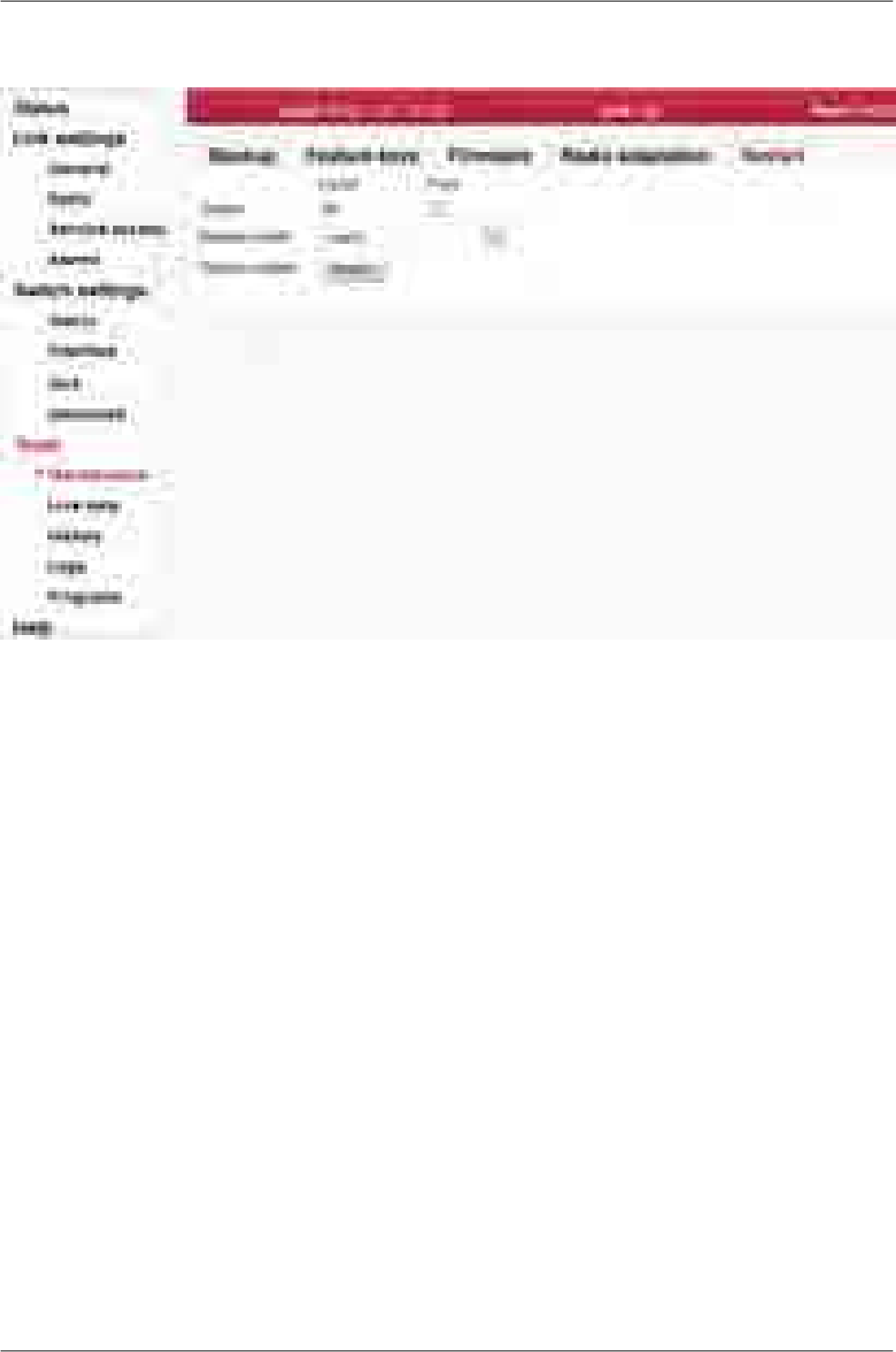
Restart
Fig. 7.47: Menu Tools - Restart
Target Restart of selected unit, Local or Peer.
Restart mode Reboot management system.Warm
Restart the whole station as if power was removed.Cold
System restart Performs the selected restart.
149© RACOM s.r.o. – RAy2 Microwave Link
Configuration
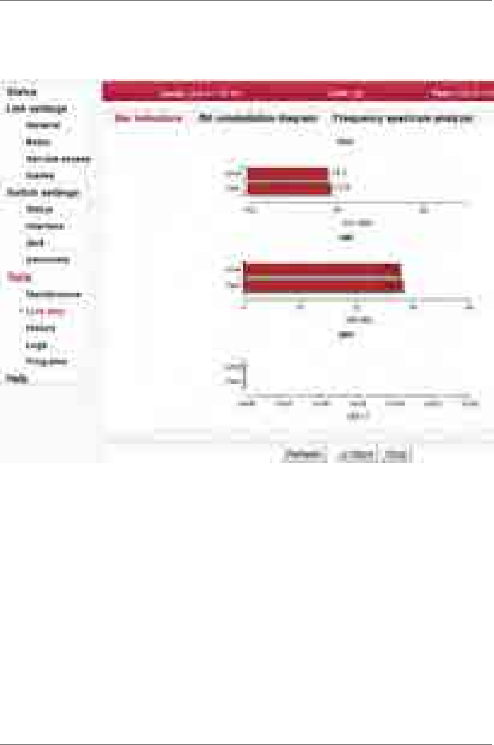
7.6.2. Live data
Bar indicators
Fig. 7.48: Menu Tools - Bar indicators
Graphical indication of BER, SNR and RSS.
Refresh One-time update of displayed values.
Start, Stop Use the Start button to start automatic update of displayed values with a period of
1 second. Use the Stop button to stop it.
RAy2 Microwave Link – © RACOM s.r.o.150
Configuration
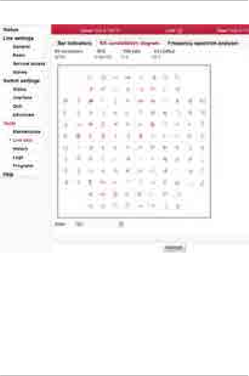
RX constellation diagram
Fig. 7.49: Menu Tools - RX constellation
Constellation diagram shows the quality of received signal.
RX modulation Modulation level of RX channel.
Buffer Number of plotted points.
Refresh One-time update of diagram.
151© RACOM s.r.o. – RAy2 Microwave Link
Configuration
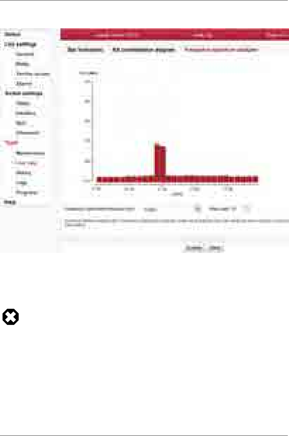
Frequency spectrum analyzer
Fig. 7.50: Menu Tools - Frequency analyzer
A very useful tool for identifying in-band interference and locating a free channel. It is not a full-blown
spectrum analyzer as it scans the spectrum with 7MHz channel resolution. The accuracy of measured
results is given by the accuracy of measuring RSS.
Warning
Running spectrum measurement causes interruption of user data flow between stations!
Enable Opening analyzer functions.
Start Interrupts communication on the link and starts scanning frequencies in the band.
Spectrum
measure time Selection of measurement length in range:
single sweep … up to 15 min
Mute peer TX The deactivation of Peer station transmission during measurement.
After using the analyzer visit any of the Link menu settings and select Refresh. This restores the con-
figuration connection (message Peer: n/a ).
RAy2 Microwave Link – © RACOM s.r.o.152
Configuration
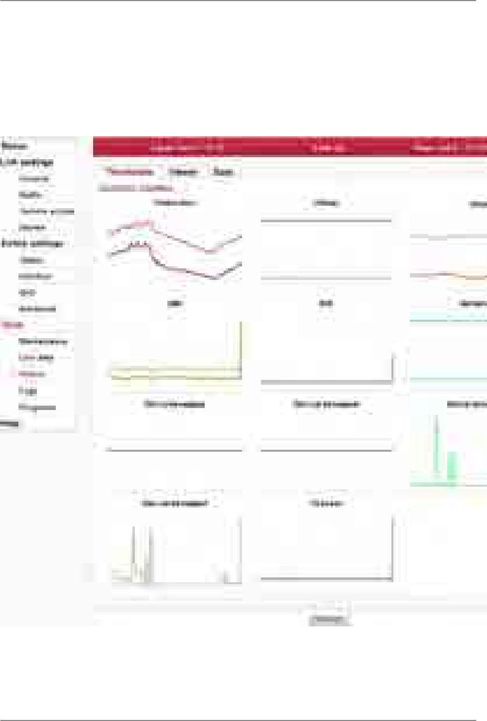
7.6.3. History
The unit continuously stores information about the values of important variables. Stored values can be
viewed using three methods - Thumbnails, Viewer and Data
Thumbnails
Preview all values for the last 24 hours. Click on a thumbnail to open the viewer with a chart.
Fig. 7.51: Menu Tools - History - Thumbnails
Instantaneous value of temperature inside the unit. Measured on the modem
board. Temperature of radio board is available via SNMP.
Temperature
153© RACOM s.r.o. – RAy2 Microwave Link
Configuration
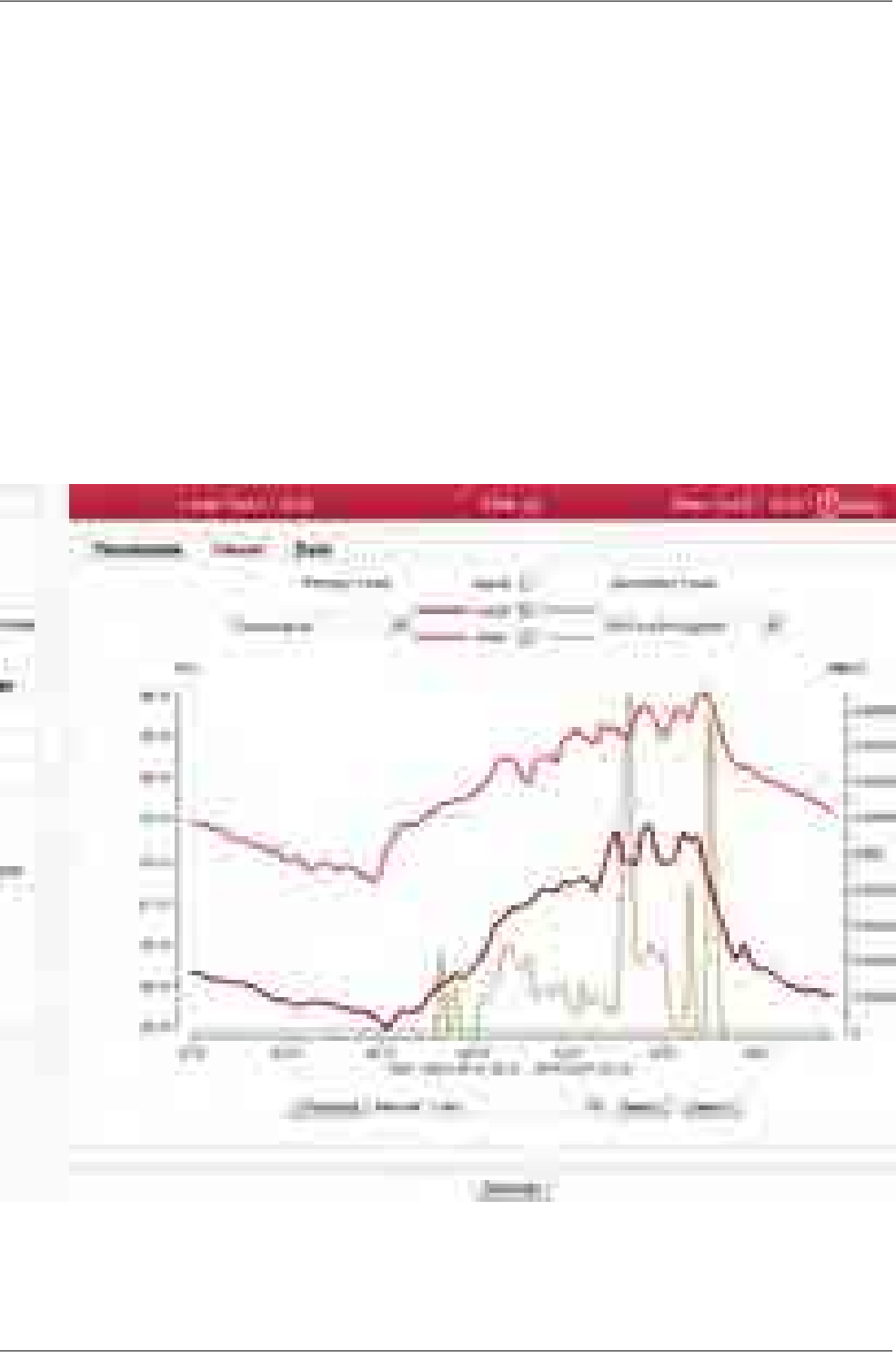
Instantaneous value of unit supply voltage.Voltage
Received signal strength.RSS
Signal-to-noise ratio of the received signal.SNR
Instantaneous bit error rate on link.BER
Instantaneous transmission capacity.Net bitrate
Instantaneous speed (20s average) of incoming user data on the user Eth-
ernet port.
Eth1, Eth2 in
throughput
Instantaneous speed (20s average) of outgoing user data on the user Eth-
ernet port.
Eth1, Eth2 out
throughput
Instantaneous value of transmission power.TX power
Viewer
Detailed graphical view of one or two selected values for the given interval. You can choose to view
data from Local or Peer or both.
Fig. 7.52: Menu Tools - History - Viewer
RAy2 Microwave Link – © RACOM s.r.o.154
Configuration

The values are saved in the following resolutions and history lengths:
Resolution 1 minute, length of history 7 days
Resolution 15 minutes, length of history 30 days
Resolution 1 day, length of history about 180 days
Interval Selecting width of interval to be displayed. Based on the interval width, data is
displayed in a suitable grid: Up to 3 hours at one minute. Up to 4 days at 15 minutes.
For longer intervals at one day.
HistoryResolutionInterval
7 days1 minute1 hour - 3 hours
30 days15 minutes6 hours - 4 days
180 days1 day1 week - 6 months
More options:
Previous Move by one width of selected interval towards older values.
Next Move by one width of selected interval towards newer values.
Last Move to the newest values.
Primary Y axis Selecting one of the observed values:
Temperature, Voltage, RSS, SNR, BER, Net bitrate, Ethernet in throughput,
Ethernet out throughput, TX power
Secondary
Y axis Selecting a second value:
None
Temperature, Voltage, RSS, SNR, BER, Net bitrate, Ethernet in throughput,
Ethernet out throughput, TX power
Alarm Enables the display of alarms, if there were any.
155© RACOM s.r.o. – RAy2 Microwave Link
Configuration
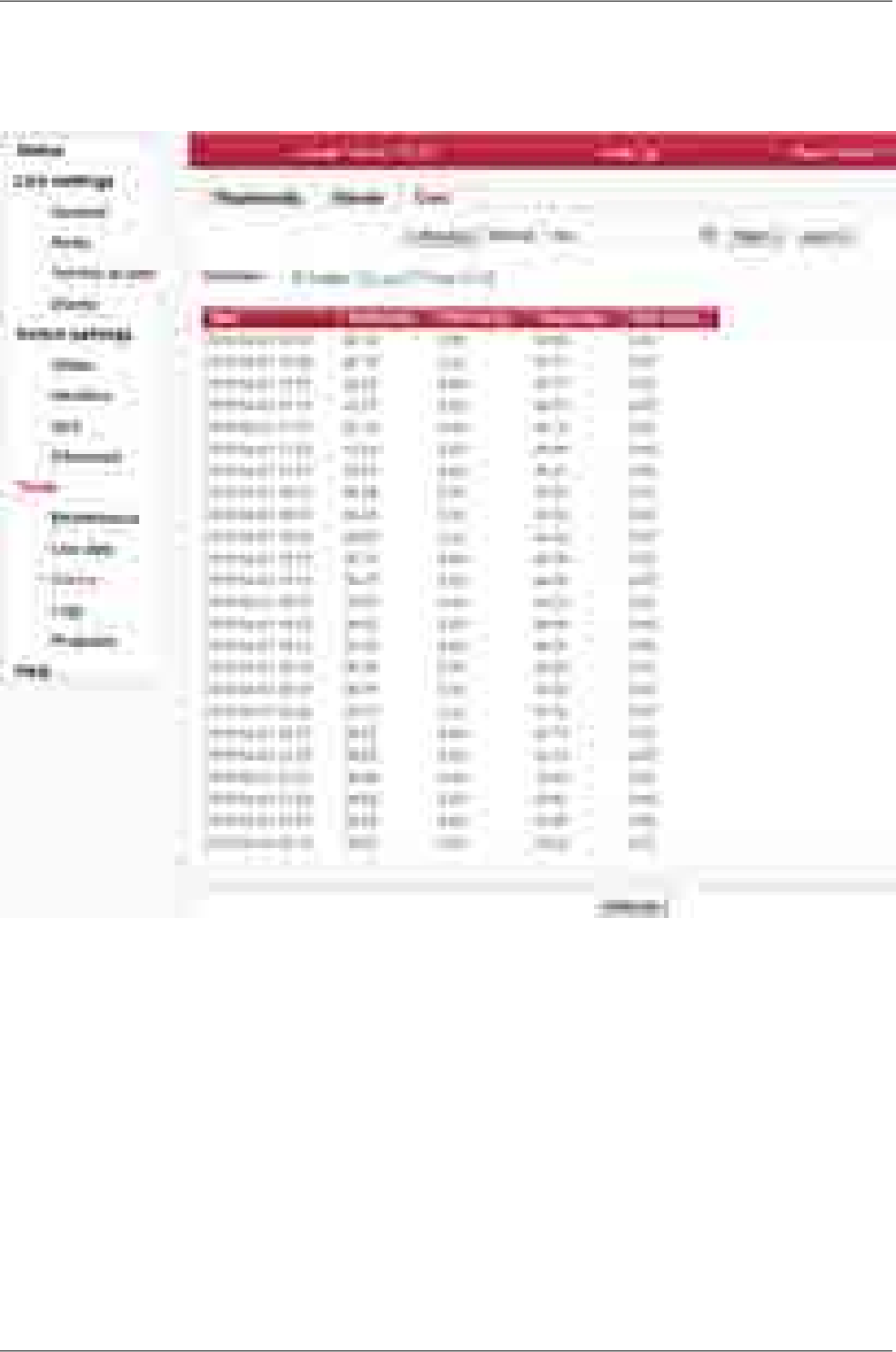
Data
Numerical view of all values
Fig. 7.53: Menu Tools - History - Data
Quantities Detailed graphical view of values for selected interval.
Plotted - Shows only the values that are selected for the graph.
Local, Peer, All - Shows all logged values. Filtering of values from local, remote
or both.
RAy2 Microwave Link – © RACOM s.r.o.156
Configuration
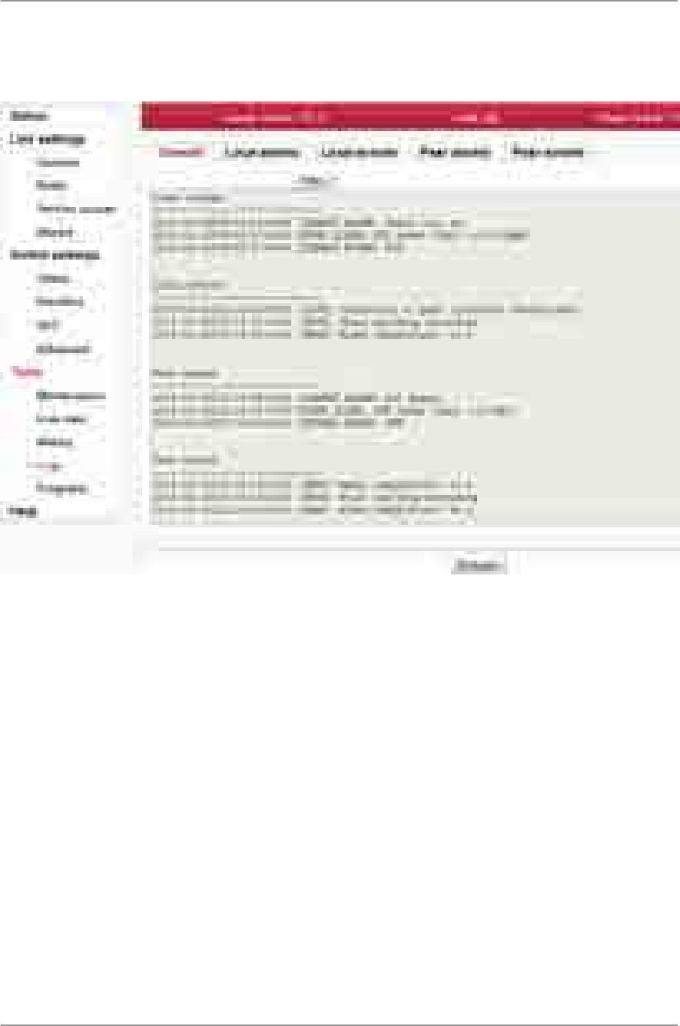
7.6.4. Logs
Shows internal unit logs. Individual tabs allow total or filtered view.
Fig. 7.54: Menu Tools - Logs
When you first open the screen, it is necessary to start browsing logs by pressing the Refresh button.
Maximum length of displayed logs is 250 entries. If you need to display longer history, use of CLI interface
is needed.
Overall Displays the last 3 records from all types of logs.
Local alarms,
Peer alarms Alarms from Local or Peer unit.
Local events,
Peer events Events from Local or Peer unit.
Filter Listings of all logs can be filtered. You can enter text in the upper left corner window
for filtering listings. For example, you want to know when the configuration of the
unit was modified: On the Local events screen, enter Configuration and hit Enter.
You can use plain text or regular expressions for filtering (JavaScript format).
157© RACOM s.r.o. – RAy2 Microwave Link
Configuration
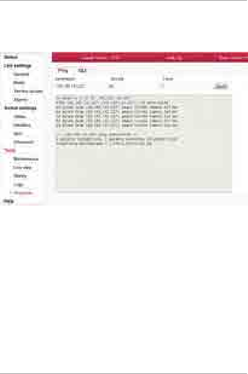
7.6.5. Programs
Ping
The Ping tool allows sending ICMP pings to a selected address
Fig. 7.55: Menu Tools - Programs - Ping
Start the test by clicking on Send. The result is displayed in the text window.
Destination Destination address in dotted decimal notation. The default address 127.0.0.1 is
the localhost address - i.e. the unit itself.
Size [B] Length of sent data 7 to 1500 bytes, 8 bytes of the header will be added.
Count Number of sent pings.
The period for sending pings is constant: 1000 ms.
RAy2 Microwave Link – © RACOM s.r.o.158
Configuration

CLI
Web interface for executing non-interactive scripts and programs.
Fig. 7.56: Menu Tools - Programs - CLI
Manage custom
commands Using "Open file upload"/"upload" the user can upload scripts to the unit. The
uploaded file can be either a single shell script with extension .sh (e.g.
my_script.sh) or package with multiple scripts with extension .tar.gz or .tgz created
using tar.
"Delete all" removes all custom scripts from the unit.
Custom scripts are located in /home/shared/bin.
Custom com-
mands A custom script can be selected here and initial comments/help is shown.
CLI commands A CLI command can be selected here. You can use cli_help for listing all CLI
commands or <command> --help to obtain detailed help on a selected command.
Command Command line for writing commands with parameters. You can use any non-in-
teractive program/script according to your permissions.
Format of custom
scripts Custom scripts must be a shell script with preamble #!/bin/sh and extension sh.
Blocks of lines beginning with the comment sign (#) after preamble are considered
to be help and are listed when the script is selected in the web interface.
Scripts should not be interactive as there is no possibility to send a response
from the web interface. All script options should be implemented as parameters.
Syntax should be valid for interpret shell ash from BusyBox v1.20.1.
Example of
custom script
159© RACOM s.r.o. – RAy2 Microwave Link
Configuration

#!/bin/sh
#script checkes if service with the same name or vid already exists
#if not creates a new entry in VTU with given VID
#
# input parameters:
# service_name - name of the new service
# VID - vid of the new service
#
# return values:
# 0 - ok
# 3 - bad parameter
# 5 - service already exists
# 6 - there already exists an entry with given VID
# 42 - other error
D42_NAME="$1"
D42_VID="$2"
D42N="service_data42"
error()
{
echo "$D42N: Error: $*" >&2
}
info()
{
echo "$D42N: $*" >&2
}
die()
{
error "$*"
exit 42 #error
}
# basic check if not empty
if [ -z "$D42_NAME" ]; then
error "Bad service name"
exit 3
fi
if [ -z "$D42_VID" ]; then
error "Bad service VID"
exit 3
fi
D42_FOUND=$(cli_nw_get --vtu all | grep "$D42_NAME")
if [ -n "$D42_FOUND" ]; then
error "Service(s) with name $D42_NAME found"
echo $D42_FOUND
exit 5
fi
RAy2 Microwave Link – © RACOM s.r.o.160
Configuration

D42_VALID=$(cli_nw_get --vtu "$D42_VID" | sed -n 's/^valid=\(.\+\)$/\1/p')
if [ "pre_$D42_VALID" = "pre_true" ]; then
error "VID $D42_VID is used"
cli_nw_get --vtu "$D42_VID"
exit 6
fi
D42_VALID=$(cli_nw_get --stu 1 | sed -n 's/^valid=\(.\+\)$/\1/p')
if [ "pre_$D42_VALID" = "pre_false" ]; then
info "Creating STU entry with SID=1"
cli_nw_set --stu 1 'label="D42_auto", port_state=["disabled", "disabled", ►
"forwarding", "disabled", "disabled", "forwarding", "forwarding"]'
if [ $? -ne 0 ]; then
die "Failed to create STU entry"
fi
fi
info "Creating service \"$D42_NAME\" with VID=$D42_VID"
cli_nw_set --vtu "$D42_VID" label="$D42_NAME" 'fid=0, sid=1, pri_override=true, priority=5, ►
policy=false, member_tag=["unmodify", "unmodify", "tag", "unmodify", "not_member", ►
"not_member", "unmodify"]'
if [ $? -ne 0 ]; then
die "Failed to create service \"$D42_NAME\" with VID=$D42_VID"
fi
161© RACOM s.r.o. – RAy2 Microwave Link
Configuration
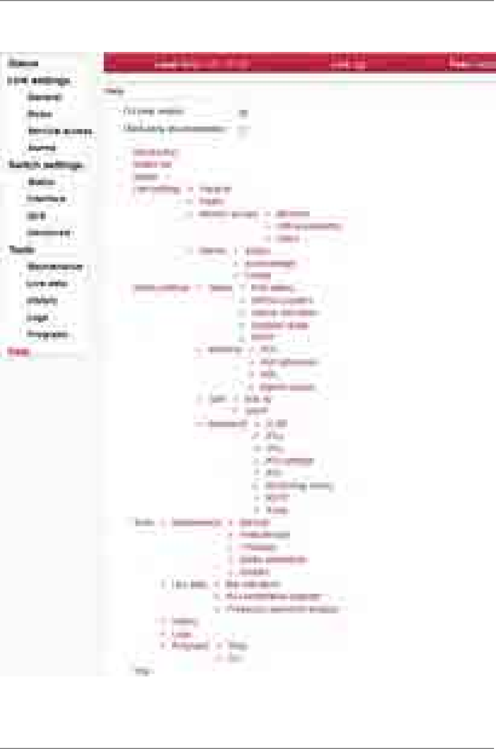
7.7. Help
Fig. 7.57: Help menu
RAy2 Microwave Link – © RACOM s.r.o.162
Configuration
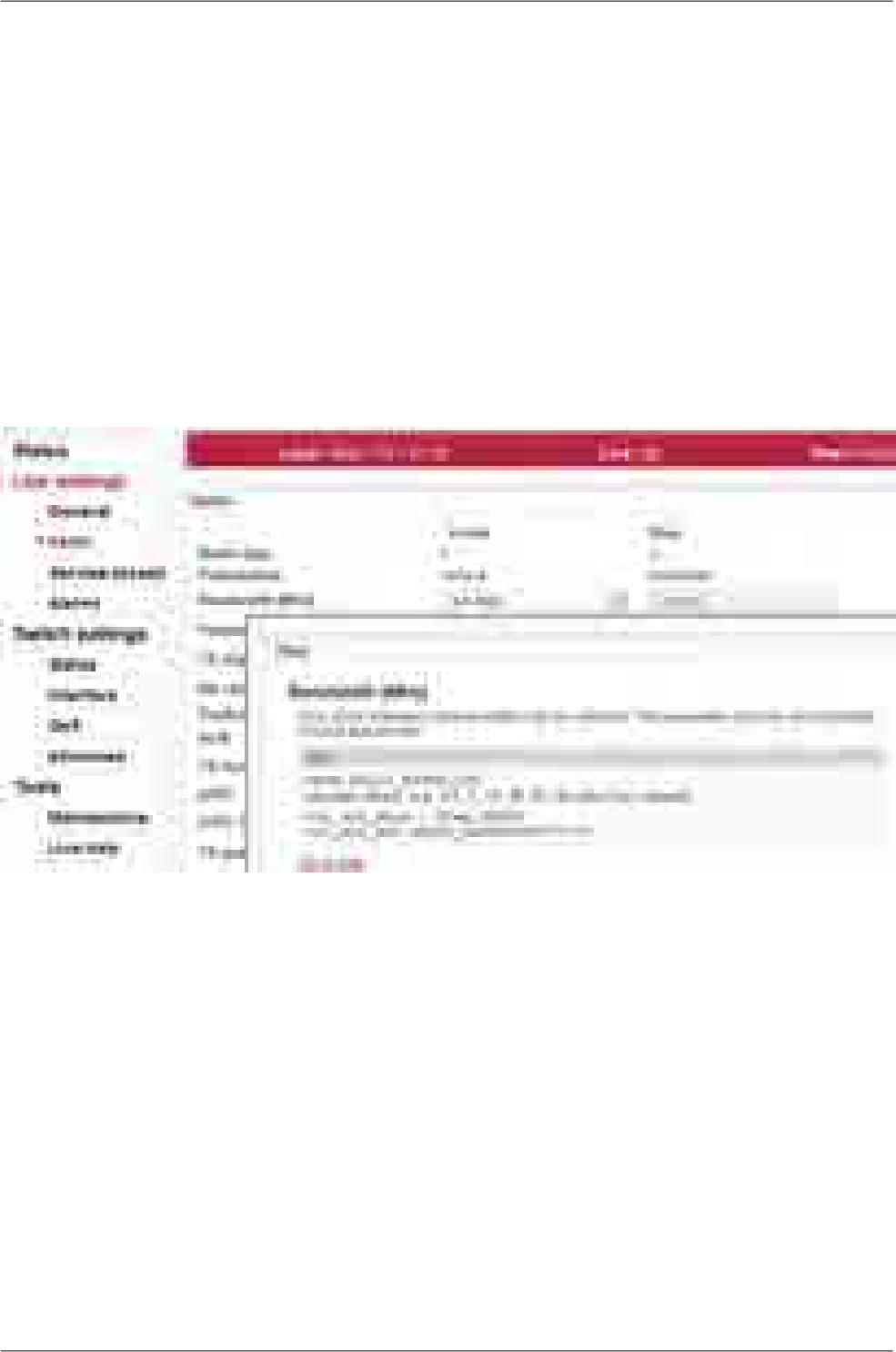
Help from Help menu
The Help screen displays contents of the embedded help. The help text is displayed in the whole con-
figuration window. The text structure corresponds to individual configuration screens. Every item of
this Help opens the specific help menu.
CLI help visible Allows displaying of the CLI help with examples.
Third party
documentation Allows displaying references to the third party documentation (e.g. internal switch
documentation).
Help from configuration menu
Clicking the name of the specific parameter in the configuration menu brings up the help belonging
to this parameter. The help text is displayed in the pop up window:
Fig. 7.58: Parameter help
There is a Go to help link within the help text. It displays the whole configuration menu help:
163© RACOM s.r.o. – RAy2 Microwave Link
Configuration
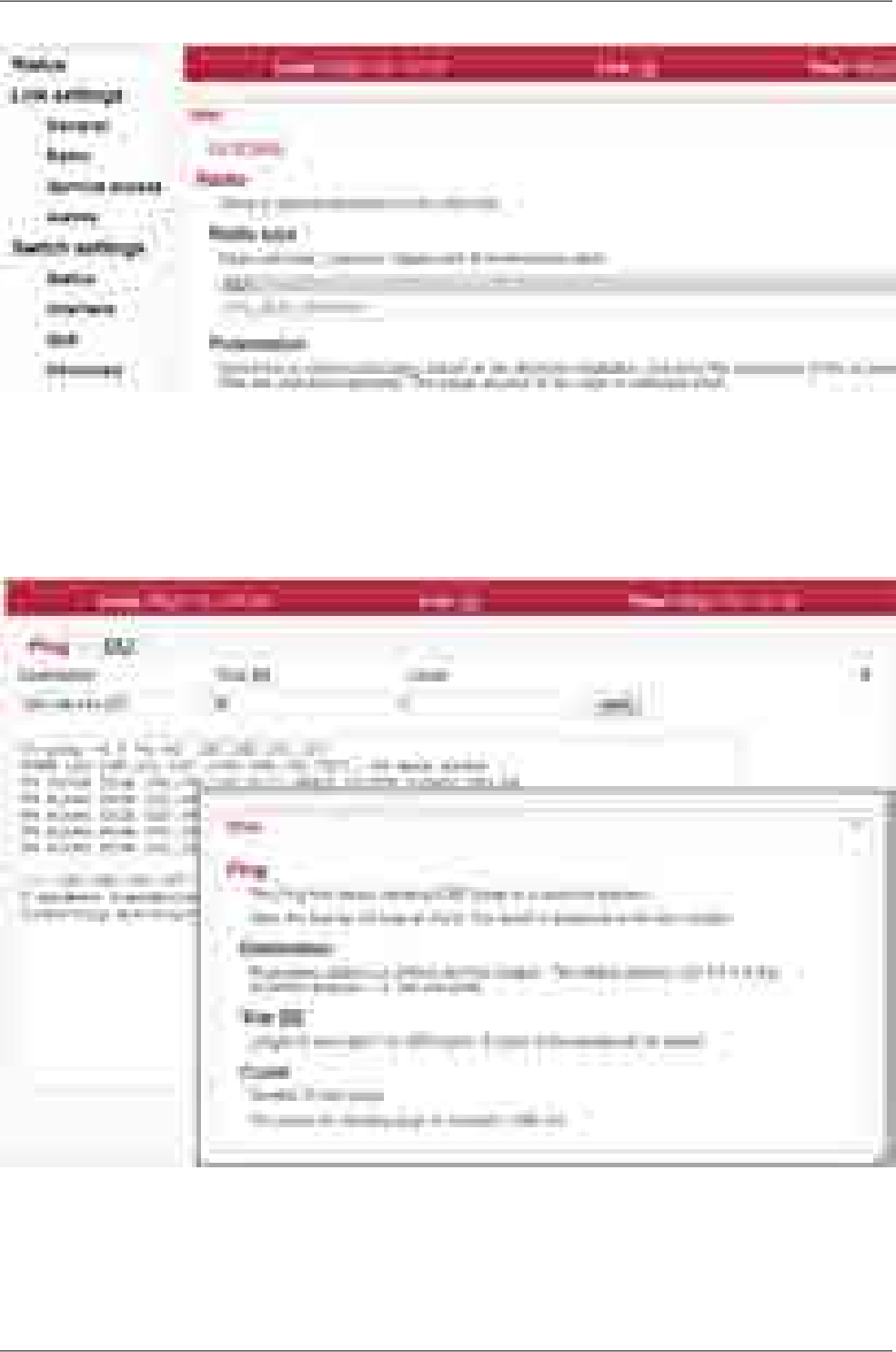
Fig. 7.59: Configuration menu help
There is a link on each help screen which points to the respective configuration screen.
Clicking the question mark icon in the upper right corner of the configuration screen brings a summary
help for the configuration screen in the pop up window:
Fig. 7.60: Summary help
The Help window can be moved by dragging the Hints bar. Resize it by dragging the bottom corner.
RAy2 Microwave Link – © RACOM s.r.o.164
Configuration

8. Command Line Interface
The Command Line Interface (CLI) provides an alternative to HTTPS access. CLI allows you to work
in a text regime interface using an ssh (putty) or telnet client.
8.1. Connection via CLI
8.1.1. Telnet
Use the telnet client to connect to the unit with service IP address 192.168.169.169. Type this in the
command prompt:
telnet 192.168.169.169
Then use the username and password from the menu Service access/Users for https access
(by default admin, admin). This works if Service access/Services/Telnet is checked in
https access.
8.1.2. Putty
Connection using putty client. Type this into the Host Name (or IP address) field:
admin@192.168.169.169
Click Open. Then enter the password admin. This procedure (without key) is subject to selection
Service access/Services/SSH on in https access.
If you own the private key part, then you do not need a password. In putty, continue by selecting
Connection/SSH/Auth and selecting path to file with key e.g. key.ppk. Use Session/Logging
to save the putty configuration. To access the unit via CLI simply select the connection in putty and
click Open.
8.1.3. SSH
Connection using client ssh in Linux.
ssh admin@192.168.169.169 -i key
If you know the password and it is enabled in Service access/Services/SSH onlykey in https
access, you can skip the key and use password in the next query.
165© RACOM s.r.o. – RAy2 Microwave Link
Command Line Interface
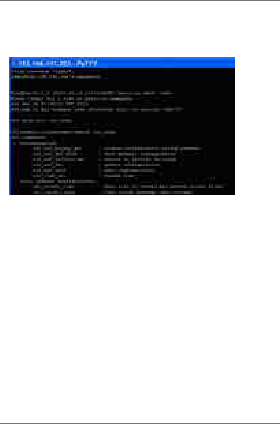
8.2. Working with CLI
• Overview of CLI options
cli_help
Fig. 8.1: CLI menu
• Parameters of CLI commands are listed in the help. For example:
help listing-h
target unit-t
local, default option-t l
both, both units, command item for remote unit has PEER_ prefix-t b
peer, opposite unit, when reading using the show command-t p
• When inserting commands, using the tabulator can help
• An incorrect command is rejected (e.g. inserting forbidden frequency)
• A parameter that caused the loss of the connection is restored after 1 minute (Rollback)
• Reading parameters of local unit
cli_cnf_show
• Reading radio parameters of peer unit
cli_cnf_show -t p | grep RADIO
• Entering parameters (TX power of local unit)
cli_cnf_set RADIO_TX_PWR=-3
Items of command (RADIO_TX_PWR=) are taken from the list cli_cnf_show
RAy2 Microwave Link – © RACOM s.r.o.166
Command Line Interface

• Entering more parameters in both units
cli_cnf_set -t b RADIO_TX_CHAN=17128000 PEER_RADIO_RX_CHAN=17128000
• Put parameters containing spaces in quotation marks:
cli_time_set -t b -T '2012-11-27 10:55:00'
Set time in both units
8.2.1. SSH keys
• Generation using ssh-keygen
[user@laptop ~]$ ssh-keygen -t dsa -f usr_ssh_key
Uses working directory to save private usr_ssh_key and public part of the key usr_ssh_key.pub
• Copying the key into the RAy2 unit
[user@laptop ~]$ scp usr_ssh_key.pub admin@192.168.141.202:/tmp
The public part of the key is written to the folder /tmp
• Installation of key in RAy2 unit
CLI(admin):/rrusrhomes/admin$ cli_user_authkey -c a -k /tmp/usr_ssh_key.pub
• Testing access to RAy2 unit using SSH key
[user@laptop ~]$ ssh -i usr_ssh_key admin@192.168.141.202
8.2.2. Scripts
• Script example with access using key
[user@laptop ~]$ ssh -i usr_ssh_key admin@192.168.141.202
"source /etc/profile;cli_info_link;echo \$?;cli_cnf_show | grep TX_PWR;echo $?"
Warning: Permanently added '192.168.141.202' (DSA) to the list of known hosts.
cli_info_link: Link status: up
0
RADIO_TX_PWR=4
0
[user@laptop ~]$
• The script contains:
environment settingssource /etc/profile;
query for link statuscli_info_link;
reading return valueecho \$?;
query for radio powercli_cnf_show | grep TX_PWR;
reading return valueecho \$?
return valuecli_info_link: Link status:up
OK command0
power +4 dBmRADIO_TX_PWR=4
OK command0
167© RACOM s.r.o. – RAy2 Microwave Link
Command Line Interface

8.3. Configuration with CLI
8.3.1. Configuration file
• Configuration backup
cli_cnf_backup_get
Saves the configuration of both units to file cnf_backup.tgz into the working directory.
• Configuration restore
cli_cnf_set -t b -b cnf_backup.tgz
Restores configuration of both units from file cnf_backup.tgz
• Default configuration list
cli_cnf_def_show
Warning, the command
cli_cnf_factory_set
is not a default setting - it uses factory settings, deleting all logs and saved data. It is very likely that
the connection to peer unit will be interrupted!
8.3.2. Firmware upgrade
• Current version of fw
cli_info_station
• Preparation of files
fw package, for example bm4-RACOM-0.1.12.0.cpio copy using ssh or putty into folder /tmp
in RAy17
Command
cli_fw_clear_buffer
Clears the RAy2 buffer
cli_fw_buffer_status
Checks buffer status
• Saving into buffers
cli_fw_load_package -f /tmp/bm4-RACOM-0.1.12.0.cpio
A new fw package is loaded into the buffer (20 sec)
cli_fw_upload2peer
The fw package is also loaded into the peer unit (20 sec)
• Upgrade
cli_fw_upgrade -t b
Firmware in both units will be replaced with new version from the buffer. After 3 minutes, this message
appears:
Firmware upgrade started. Estimated time to finish is 370 s.
Connection is terminated. After a few minutes, log in to RAy2 again
8.3.3. Remote unit authorization
The RAy2 unit in default configuration, establishes a connection with any remote unit and both units
act as a communication pair. Should the higher protection from the unauthorized communication take-
over be required, it is possible to use the so called Secured mode of remote unit authorization. This
mode is based on locking the two specific units into one communication pair. Units with Secured mode
RAy2 Microwave Link – © RACOM s.r.o.168
Command Line Interface

activated refuse to make a connection with any other communication unit. The units are locked using
the unique authorization keys. The keys are exchanged between the units concerned. The authorization
keys can be backed up to an external medium to be able to make a service unit exchange, if necessary.
Should The Link authorization quard be disabled, the user data occurs even it the remote unit is not
authorized.
The Secured mode set up process consists of a few steps:
• Unique authorization keys generation:
cli_link_key_gen -t b
• Authorization keys exchange between the two communication units:
cli_link_key_swap
• Authorization keys activation:
cli_link_key_apply -t b
Parameter -t determines whether we configure the whole link (-t b) or only one unit (-t l).
• Secured mode activation. Both sides of the link must have identically secured mode set On or Off:
cli_cnf_set -t b SVC_SECURE_PEER_MODE=on PEER_SVC_SECURE_PEER_MODE=on
• Secured mode de-activation:
cli_cnf_set -t b SVC_SECURE_PEER_MODE=off PEER_SVC_SECURE_PEER_MODE=off
• Backup of the keys to an external medium. The backup has to be performed to be able to make
service exchange of the corrupted unit, if necessary. The new exchanged unit is not able to make
an active connection with the other unit if it is not loaded with the proper authorization key.
cli_link_key_save -s s -f <file>
The key is backed up to a selected file in the internal unit file system. It can be transferred to an
external medium using for example the scp client.
• Authorization key restoration from the external medium.
The key has to be transferred to the unit internal file system first. The scp client can be used. The
CLI commands can be applied subsequently:
cli_link_key_load -t b -f <file>
cli_link_key_apply -t b
169© RACOM s.r.o. – RAy2 Microwave Link
Command Line Interface

9. Troubleshooting
•Polarization incorrect
Install the unit with the correct horizontal or vertical polarization: The arrow mark (placed just next
to the Status LED) indicates the unit RX polarization. When the arrow is perpendicular to the earth,
the unit receives a signal in vertical polarization. When the arrow is parallel to the earth, the unit
receives a signal in horizontal polarization. The connectors must point downward at an angle.
•The link cannot be established
Start with the most “resilient” configuration. This configuration depends on the type of unit. We re-
commend using the narrowest available bandwidth (e.g. 3.5 MHz), the lowest modulation level
(QPSK) and maximum available output power. TX and RX channels must be the same as the RX
and TX channels in the remote unit. When the connection has been established and the antennas
have been directed, proceed with operation parameters.
Units operating in licensed bands (RAy2-10, RAy2-11) are mounted with the same RX polarization
(the polarization indication arrows show the same polarization on both units).
Units working in the bands equipped with RAy2-17 and RAy2-24 units must be mounted with opposite
polarization; one with RX horizontal polarization (horizontal arrow) and the second with RX vertical
polarization (vertical arrow).
•Access to the Local unit is blocked
Access to the Local unit may be accidentally blocked, for instance by disabling HTTPS access. If
you can access the Remote unit over HTTPS, type its address in your web browser's address field.
The link will transfer the packet over the Local unit with blocked service access all the way to the
Remote unit, which will give you access to the control menus of both units. Warning, the Remote
unit will report as Local.
•Distinguishing Local-Remote
A unit accessed via service access always reports as Local. If you connect through another (peer)
unit and radio channel, a certain amount of caution is necessary. For example, do not reduce the
transmission power so that the link interrupts accidentally. Errors of this type should be fixed by the
rollback function within approx. 1 minute.
Resolution can be done by comparing the length of ping on Local and Remote. Pinging the unit
behind the radio channel is slower. The difference is more pronounced in the case of a long packet
and the low speed of the radio channel.
•Access security
For better protection against unauthorised access to configuration you should only allow as few
kinds of access as possible. The most secure type is SSH with key – leave only SSH active with
"only key" choice.
•RSS
To configure the link and monitor its state, several menus display the RSS signal strength. Please
keep in mind, that Ray2 is not a measuring instrument, hence the precision of the RSS reading is
RAy2 Microwave Link – © RACOM s.r.o.170
Troubleshooting

limited. Though, in most situations the RSS reading accuracy is better than ± 2dB, the absolute
RSS value should not be used for accurate comparisons e.g. between two links.
•Problem with https certificate
See the Appendix G, Https certificate
•Overexcited receiver
A natural property of each radio receiver is to compress the signal in one of the functional blocks,
typically in a second receiving mixer. A downside of this property is the distortion of the input signal
(decrease in the signal to noise ratio, i.e. the distortion measured as SNR).
In extreme cases, this can lead to the disintegration of the radio link due to reduced signal to noise
ratio (distortion). Extreme limits for guaranteed availability of the RAy2 connections are:
○ -30 dB for all channel bandwidths and fixed modulation 256QAM
○ -10 dB for all channel bandwidths and fixed modulation QPSK
171© RACOM s.r.o. – RAy2 Microwave Link
Troubleshooting

10. Technical parameters
10.1. General parameters
10.1.1. Technical parameters overview
Tab. 10.1: Technical parameters
RAy2-24RAy2-17RAy2-11RAy2-10Type
24.0 – 24.2517.1 – 17.3
A:A:
Band [GHz],
sub-bands A,B..
10.695 – 11.46010.30 – 10.59
B:B:
10.935 – 11.69510.125 – 10.675
One universal unitUnit L and UODU inits
optional
min 60
optional
min 60
490, 530any combination
L and U units
Duplex
spacing [MHz]
3.5, 7, 14, 28,
40, 50, 56
3.5, 7, 14, 28,
40, 50, 56
1.75, 3.5, 7, 14, 28,
30, 40, 56
1.75, 3.5, 7, 14, 20,
28, 56
Channel spacing
CS [MHz]
detaildetaildetaildetailChannel freq.
4.9 – 3604.9 – 3602.5 – 3602.5 – 360
User speed
[Mbps] detaildetaildetaildetail
81 (64B/359Mbps),
234 (1518B/359Mbps)
Latency [μs]
-96 (4.9 Mbps)
-65 (340 Mbps)
-96 (4.9 Mbps)
-66 (340 Mbps)
-99 (2.5 Mbps)
-67 (340 Mbps)
-100 (2.5 Mbps)
-67 (340 Mbps)
Sensitivity,
BER 10-6 [dBm] detaildetaildetaildetail
-30 – +10-25 – +5
-15 – +24 (QPSK)
-15 – +19 (256QAM)
-10 – +13 (QPSK)
-10 – +8 (256QAM)
Output Power
[dBm]
yesyesyesyesATPC
232121 – 2921Consumption [W]
2.52.52.82.8Weight [kg]
EN 300 440-2 V1.4.1EN 302 217-2-2 V2.1.1Radio param.
ver. 2.11
RAy2 Microwave Link – © RACOM s.r.o.172
Technical parameters

fixed QPSK, 16, 32, 64, 128, 256 QAM or ACMModulation
LDPCForward Error Correc.
1 Gb Eth. (10/100/1000) (IEEE 802.3ac 1000BASE-T) , MTU 10240 B,
recommended cable S/FTP CAT7
User interface RJ45
1000Base‐SX / 1000Base‐LX, MTU 10240 B, user exchangable SFP, power
consumption max. 1.25 W
User interface SFP
USB-AService
PoE, 40 - 60 VDC , IEEE 802.3at up to 100m, up to 25 WPower
DC, 20 - 60 V, floating
-30 – +55°C (EN 300 019-1-4, class 4.1.)Operating temperature
range
FOD (Full Outdoor)Mechanical design
IP66 (Ingress Protection)IP code
configuration via https, sshSecurity
244 × 244 × 157 mmDimensions
EN 301 489-1 V1.9.2
EN 301 489-4 V2.1.1
EMC
EN 60 950-1:2006Electrical safety
ver. 1.4
173© RACOM s.r.o. – RAy2 Microwave Link
Technical parameters

10.1.2. Link speed
Nominal link speed
User data rate [Mbps]RAy2 - xx
56
MHz TO
56
MHz
50
MHz
40
MHz
28 / 30
MHz
20
MHz
14
MHz
7
MHz
3.5
MHz
1.75
MHz
Modula-
tion ACCPACCPACCPACCPACAPACCPACCPACCPACCPACCPACCP
85.872.966.350.138.336.822.819.98.54.92.5QPSK
169.9160.2145.6110.084.180.950.238.817.29.64.916-QAM
206.2202.7184.2139.2106.4102.463.549.122.112.16.332-QAM
268.1256.9233.6176.5135.0129.880.562.329.714.37.464-QAM
309.0303.7276.1211.4161.7155.596.473.634.717.28.9128-QAM
358.9337.7320.6232.1185.2170.7110.481.240.719.7256-QAM
ver. 2.7
Link speed according to RFC 2544
valuesLink speed [Mbps] for frames 64 - 1518 BRAy2 - xx minimum
maximum
56MHzTO56 MHz40 MHz28 / 30 MHz14 MHz7 MHz3.5 MHz1.75 MHz
Modulation
/ CS ACCPACCPACCPACAPACCPACCPACCPACCPACCP
76.1
85.2
64.7
72.3
44.3
49.6
33.8
37.9
32.6
36.5
17.6
19.6
7.5
8.3
4.2
4.6
2.1
2.3
QPSK
150.7
168.6
142.1
159.0
97.5
109.2
74.6
83.4
71.7
80.2
34.3
38.5
15.1
17.0
8.4
9.3
4.3
4.8
16-QAM
182.9
204.8
179.9
201.3
123.4
138.2
94.3
105.6
90.7
101.5
43.4
48.6
19.6
21.8
10.6
11.9
5.4
6.0
32-QAM
238.1
266.4
228.0
255.1
156.6
175.3
119.7
133.9
115.1
128.8
55.2
61.7
26.1
29.3
12.6
14.1
6.5
7.2
64-QAM
274.5
307.1
269.7
301.6
187.7
209.9
143.5
160.5
138.0
154.5
65.2
73.0
30.7
34.3
15.1
17.0
7.8
8.7
128-QAM
318.8
356.5
300.2
335.8
206.1
230.7
164.4
184.0
151.5
169.5
71.9
80.5
36.1
40.3
17.4
19.4
256-QAM
ver. 1.1
RAy2 Microwave Link – © RACOM s.r.o.174
Technical parameters

ACM switching according to SNR state
SNR degrade / improve [dB]RAy2 - xx
56
MHz TO
56
MHz
50
MHz
40
MHz
28
MHz
20
MHz
14
MHz
7
MHz
3.5
MHz
1.75
MHz
Modulation
/ CS ACCPACCPACCPACCPACCPACCPACCPACCPACCPACCP
-
19.0
-
19.0
-
19.0
-
19.0
-
19.0
-
19.0
-
19.0
-
19.0
-
19.0
-
19.0
QPSK
17.0
23.0
17.0
23.0
17.0
23.0
17.0
23.0
17.0
23.0
17.0
23.0
17.0
23.0
17.0
23.0
17.0
23.0
17.0
23.0
16-QAM
20.5
26.0
20.0
26.0
20.0
26.0
20.0
26.0
20.0
26.0
20.0
26.0
20.0
26.0
20.0
26.0
20.0
26.0
20.0
26.0
32-QAM
24.5
28.5
23.0
28.5
23.0
28.5
23.0
28.5
23.0
28.5
23.0
28.5
23.0
28.5
23.0
28.5
23.0
28.5
23.0
28.5
64-QAM
27.0
31.0
25.0
30.5
25.0
30.5
25.0
30.5
25.0
30.5
25.0
30.5
25.0
30.5
25.0
30.5
25.0
31.5
25.0
-
128-QAM
29.0
-
28.0
-
28.0
-
28.0
-
28.0
-
28.0
-
28.0
-
28.0
-
28.5
-
-
-
256-QAM
ver. 1.2
FCC comment
Choice of modulation must respect the requirements of Section 11.9, “FCC authorization of transmitters”.
175© RACOM s.r.o. – RAy2 Microwave Link
Technical parameters

10.2. Nominal frequency tables description
1) TX channel nominal frequencies
Band 10.7 – 11.7 GHz,
3)
duplex frequency 490 MHz
4)
2) CEPT 12-06 Annex C 5)
6)
(Freq.table: rcinfo11_A_490, rcinfo11_A_490_n)
7) (Freq.table: rcinfo11_B_490, rcinfo11_B_490_n)
Ch.No.
Lower [MHz] Upper [MHz]
Ch.No.
Lower [MHz] Upper [MHz]
18) 10755 9) 11245 10) 7 10995 11485
2 10795 11285 8 11035 11525
3 10835 11325 9 11075 11565
4 10875 11365 10 11115 11605
5 10915 11405 11 11155 11645
ver. 1.0 11)
RAy11 – xA , RAy11 – xB
Bandwidth: 56 MHz (CS 80)
A sub-band B sub-band
1) The respective RAy unit name. The letter “x” stands for “L” or “U” (Lower or Upper band unit).
Example: “RAy11-xA” means both “RAy11-LA” and “RAy11-UA” units. See overview table for
details.
NOTE: The optional last figure in the unit name (e.g. RAy11-LA-2) denotes number of Ethernet
ports and it is not relevant for the Nominal frequency tables.
2) The respective channel set (nominal frequencies) name in the Ray unit configuration interface
(see Configuration, item “Bandwith [MHz]”. In addition to the bandwith definition, the name may
contain additional text which defines the respective alternative of channel plan. Examples:
• “Bandwith: 40 MHz (ITU)” means that the nominal frequencies in the table follow the recom-
mendation ITU-R F.387 rec.1.2. for 40 MHz bandwith, see also the note 5) below.
•“Bandwith: 40 MHz (ACMA)” means that the table describes the 40 MHz channel plan defined
by ITU-R F.387 rec. 1.1. (b), applied e.g. in Australia.
3) The complete frequency range (approx.)
4) Duplex spacing – the frequency difference between the Upper and Lower channels in a duplex
pair.
Optional: The minimum and the maximal duplex spacing used in the table of frequencies.
5) The name of standard or recommendation defining the respective channel plan.
6) Name of the sub-band defined by channels in the table.
7) Name of the “Frequency table” containing the channel set described (see Configuration, item
"Frequency tables").
8) The channel number according to RAy unit configuration interface (see Configuration, item “TX
channel [GHz]”).
9) The nominal TX frequency of the Lower-band channel
10) The nominal TX frequency of the Upper-band channel.
11) Table version.
RAy2 Microwave Link – © RACOM s.r.o.176
Technical parameters
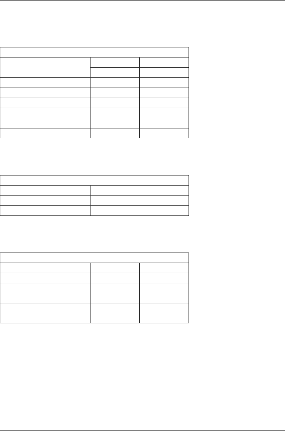
10.3. RAy2-10 parameters
10.3.1. Upper/Lower Limits
TX powerRAy2-10-xA,RAy2-10-xB
MaxMin
Modulation [dBm][dBm]
13-10QPSK
11-1016-QAM
11-1032-QAM
10-1064-QAM
9-10128-QAM
8-10256-QAM
ver. 1.2
Duplex spacingRAy2-10-xA,RAy2-10-xB
[MHz]Sub-band
All combinations of channelsA
All combinations of channelsB
ver. 2.5
Sub-band RangeRAy2-10-xA,RAy2-10-xB
Unit UUnit LSub-band
[MHz][MHz]
10.47010.300min
A10.59010.420max
10.47510.125min
B11.67510.325max
ver. 1.1
177© RACOM s.r.o. – RAy2 Microwave Link
Technical parameters
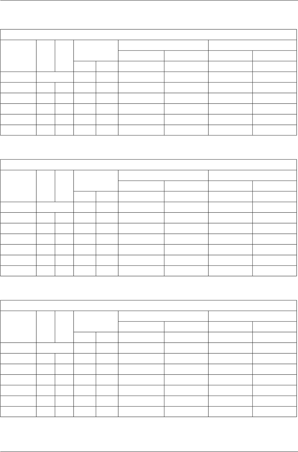
10.3.2. Radio parameters
Channel spacing 1.75 MHz; ACCP operationRAy2-10
Adjacent channel SelectivityCo-channel rejection
RSS / SNR for
BER 10-6
User
Bit
Rate
Raw
Bit
Rate
Modula-
tion
3 dB1 dB3 dB1 dB
declared / limitdeclared / limitdeclared / limitdeclared / limitSNRRSS
[dB][dB][dB][dB][dB][dBm][Mbps][-]
-4/-140/-1219/1223/179.5-1002.53.1QPSK
-7/-13-3/-1126.5/2030/2215.0-925.06.316-QAM
-7/-12-3/-1026.5/2230/2419.0-886.37.832-QAM
-7/-10-3/-926.5/2630/2920.5-877.49.464-QAM
-9/-9-5/-529/2933/3023.5-848.911.0128-QAM
ver. 2.4
Channel spacing 3.5 MHz; ACCP operationRAy2-10
Adjacent channel SelectivityCo-channel rejection
RSS / SNR for
BER 10-6
User
Bit
Rate
Raw
Bit
Rate
Modula-
tion
3 dB1 dB3 dB1 dB
declared / limitdeclared / limitdeclared / limitdeclared / limitSNRRSS
[dB][dB][dB][dB][dB][dBm][Mbps][-]
-4/-160/-1419/1223/159.5-964.96QPSK
-7/-15-3/-1326.5/2030/2215.0-899.61216-QAM
-7/-14-3/-1226.5/2230/2418.5-8612.11532-QAM
-7/-12-3/-1126.5/2630/2920.5-8514.31864-QAM
-7/-8-3/-926.5/2630/3023.5-8317.221128-QAM
-4/-60/-736/3140/3326.0-8019.724256-QAM
ver. 2.4
Channel spacing 7 MHz; ACCP operationRAy2-10
Adjacent channel SelectivityCo-channel rejection
RSS / SNR for
BER 10-6
User
Bit
Rate
Raw
Bit
Rate
Modula-
tion
3 dB1 dB3 dB1 dB
declared / limitdeclared / limitdeclared / limitdeclared / limitSNRRSS
[dB][dB][dB][dB][dB][dBm][Mbps][-]
-4/-220/-2019/1223/158.5-948.512QPSK
-7/-19-3/-1826.5/2030/2215.0-8717.22416-QAM
-9/-18-5/-1629/2233/2418.5-8422.13032-QAM
-7/-16-3/-1430/2634/2921.5-8029.73664-QAM
-6/-14-2/-1233/3037/3225.0-7834.742128-QAM
-4/-120/-1036/3140/3326.0-7639.749256-QAM
ver. 2.4
RAy2 Microwave Link – © RACOM s.r.o.178
Technical parameters
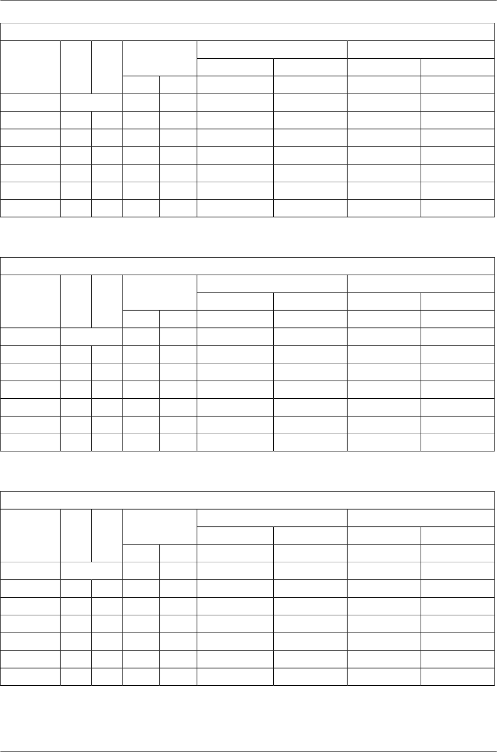
Channel spacing 14 MHz; ACCP operationRAy2-10
Adjacent channel SelectivityCo-channel rejection
RSS / SNR for
BER 10-6
User
Bit
Rate
Raw
Bit
Rate
Modula-
tion
3 dB1 dB3 dB1 dB
declared / limitdeclared / limitdeclared / limitdeclared / limitSNRRSS
[dB][dB][dB][dB][dB][dBm][Mbps][-]
-4/-230/-2119/1223/148.5-9219.924QPSK
-7/-21-3/-1926.5/1830/2015.0-8538.84816-QAM
-9/-19-5/-1729/2333/2618.5-8149.16032-QAM
-7/-17-3/-1430/2634/2821.5-7862.37264-QAM
-6/-14-2/-1233/2837/3025.0-7573.684128-QAM
-4/-120/-1036/3140/3328.0-7381.296256-QAM
ver. 2.4
Channel spacing 20 MHz; ACCP operationRAy2-10
Adjacent channel SelectivityCo-channel rejection
RSS / SNR for
BER 10-6
User
Bit
Rate
Raw
Bit
Rate
Modula-
tion
3 dB1 dB3 dB1 dB
declared / limitdeclared / limitdeclared / limitdeclared / limitSNRRSS
[dB][dB][dB][dB][dB][dBm][Mbps][-]
-4/-230/-2119/1223/148.5-9122.831QPSK
-12/-21-8/-1926.5/1830/2015.0-8450.26216-QAM
-12/-19-8/-1726.5/2330/2618.5-8063.577.532-QAM
-12/-17-8/-1426.5/2630/2821.5-7780.59364-QAM
-6/-14-2/-1233/2837/3025.0-7396.4108.5128QAM
-4/-120/-1036/3140/3328.0-71110.4124256-QAM
ver. 2.4
Channel spacing 28 / 30 MHz; ACCP operationRAy2-10
Adjacent channel SelectivityCo-channel rejection
RSS / SNR for
BER 10-6
User
Bit
Rate
Raw
Bit
Rate
Modula-
tion
3 dB1 dB3 dB1 dB
declared / limitdeclared / limitdeclared / limitdeclared / limitSNRRSS
[dB][dB][dB][dB][dB][dBm][Mbps][-]
-4/-230/-2119/1023/127.5-9036.850QPSK
-7/-20-3/-1826.5/1830/2015.0-8280.910016-QAM
-9/-19-5/-1629/2233/2418.5-78102.412532-QAM
-7/-15-3/-1230/2634/2821.5-75129.815064-QAM
-8/-12-5/-932/2835/3025.0-71155.5175128QAM
-4/-90/-636/3140/3326.5-69170.7200256-QAM
ver. 2.4
179© RACOM s.r.o. – RAy2 Microwave Link
Technical parameters
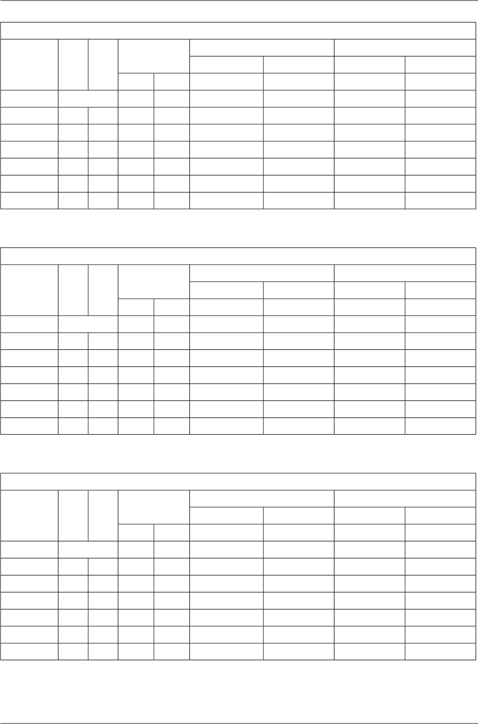
Channel spacing 28 / 30 MHz; ACAP operationRAy2-10
Adjacent channel SelectivityCo-channel rejection
RSS / SNR for
BER 10-6
User
Bit
Rate
Raw
Bit
Rate
Modula-
tion
3 dB1 dB3 dB1 dB
declared / limitdeclared / limitdeclared / limitdeclared / limitSNRRSS
[dB][dB][dB][dB][dB][dBm][Mbps][-]
-4/-170/-1519/1023/127.5-88.538.352QPSK
-7/-14-3/-1226.5/1830/2015.0-81.584.110416-QAM
-9/-13-5/-1029/2233/2418.5-77.5106.413032-QAM
1/-94/-630/2634/2821.5-74.5135.015664-QAM
7/-610/-336/2840/3025.0-70.5161.7182128QAM
6/-310/039/3143/3326.5-67.5185.2208256-QAM
ver. 2.4
Channel spacing 56 MHz; ACCP operationRAy2-10
Adjacent channel SelectivityCo-channel rejection
RSS / SNR for
BER 10-6
User
Bit
Rate
Raw
Bit
Rate
Modula-
tion
3 dB1 dB3 dB1 dB
declared / limitdeclared / limitdeclared / limitdeclared / limitSNRRSS
[dB][dB][dB][dB][dB][dBm][Mbps][-]
-4/-280/-2619/1023/127.5-8672.999QPSK
-7/-21-3/-1926.5/1730/1915.0-79160.219816-QAM
-9/-17-5/-1529/2233/2418.5-75202.7247.532-QAM
-7/-16-3/-1430/2534/2721.5-72256.929764-QAM
-8/-12-5/-1032/2835/3025.0-68303.7346.5128QAM
-4/-100/-836/3040/3326.5-66337.7396256-QAM
ver. 2.4
Channel spacing 56 MHz TO; ACCP operationRAy2-10
Adjacent channel SelectivityCo-channel rejection
RSS / SNR for
BER 10-6
User
Bit
Rate
Raw
Bit
Rate
Modula-
tion
3 dB1 dB3 dB1 dB
declared / limitdeclared / limitdeclared / limitdeclared / limitSNRRSS
[dB][dB][dB][dB][dB][dBm][Mbps][-]
-4/-260/-2419/1123/1310.0-8485.899QPSK
-7/-20-3/-1826.5/1830/2016.0-77169.919816-QAM
-9/-15-5/-1429/2333/2519.0-73206.2247.532-QAM
-7/-11-3/-930/2634/2922.5-69268.129764-QAM
-8/-10-5/-832/2935/3225.5-66309.0346.5128QAM
-4/-80/-739/3243/3527.5-63358.9396256-QAM
ver. 2.4
RAy2 Microwave Link – © RACOM s.r.o.180
Technical parameters

10.3.3. Nominal frequencies, band 10.30 – 10.59 GHz
TX channel nominal frequencies
Band 10.30 – 10.59 GHz default duplex 168 MHz
Bandwidth: 1.75 MHz
Channel arrangements based on 7 MHz channels
duplex range 57.75 – 285.25 MHz
( Freq.table: rcinfo10_A_default:6 )
Ch.No. Lower [MHz] Upper [MHz] Ch.No. Lower [MHz] Upper [MHz]
1 10301.875
2 10303.625
3 10305.375
4 10307.125
5 10308.875 10476.875 37 10364.875 10532.875
6 10310.625 10478.625 38 10366.625 10534.625
7 10312.375 10480.375 39 10368.375 10536.375
8 10314.125 10482.125 40 10370.125 10538.125
9 10315.875 10483.875 41 10371.875 10539.875
10 10317.625 10485.625 42 10373.625 10541.625
11 10319.375 10487.375 43 10375.375 10543.375
12 10321.125 10489.125 44 10377.125 10545.125
13 10322.875 10490.875 45 10378.875 10546.875
14 10324.625 10492.625 46 10380.625 10548.625
15 10326.375 10494.375 47 10382.375 10550.375
16 10328.125 10496.125 48 10384.125 10552.125
17 10329.875 10497.875 49 10385.875 10553.875
18 10331.625 10499.625 50 10387.625 10555.625
19 10333.375 10501.375 51 10389.375 10557.375
20 10335.125 10503.125 52 10391.125 10559.125
21 10336.875 10504.875 53 10392.875 10560.875
22 10338.625 10506.625 54 10394.625 10562.625
23 10340.375 10508.375 55 10396.375 10564.375
24 10342.125 10510.125 56 10398.125 10566.125
25 10343.875 10511.875 57 10399.875 10567.875
26 10345.625 10513.625 58 10401.625 10569.625
27 10347.375 10515.375 59 10403.375 10571.375
28 10349.125 10517.125 60 10405.125 10573.125
29 10350.875 10518.875 61 10406.875 10574.875
30 10352.625 10520.625 62 10408.625 10576.625
31 10354.375 10522.375 63 10410.375 10578.375
32 10356.125 10524.125 64 10412.125 10580.125
33 10357.875 10525.875 65 10413.875 10581.875
34 10359.625 10527.625 66 10415.625 10583.625
35 10361.375 10529.375 67 10417.375 10585.375
36 10363.125 10531.125 68 10419.125 10587.125
37 10364.875 10532.875
38 10366.625 10534.625 ver. 2.0
RAy2-10 – xA
A sub-band
181© RACOM s.r.o. – RAy2 Microwave Link
Technical parameters

TX channel nominal frequencies
Band 10.30 – 10.59 GHz default duplex 168 MHz
Bandwidth: 3.5 MHz
Channel arrangements based on 7 MHz channels
duplex range 59.5 – 283.5 MHz
( Freq.table: rcinfo10_A_default:6 )
Ch.No. Lower [MHz] Upper [MHz] Ch.No. Lower [MHz] Upper [MHz]
1 10302.75
2 10306.25
3 10309.75 10477.75 19 10365.75 10533.75
4 10313.25 10481.25 20 10369.25 10537.25
5 10316.75 10484.75 21 10372.75 10540.75
6 10320.25 10488.25 22 10376.25 10544.25
7 10323.75 10491.75 23 10379.75 10547.75
8 10327.25 10495.25 24 10383.25 10551.25
9 10330.75 10498.75 25 10386.75 10554.75
10 10334.25 10502.25 26 10390.25 10558.25
11 10337.75 10505.75 27 10393.75 10561.75
12 10341.25 10509.25 28 10397.25 10565.25
13 10344.75 10512.75 29 10400.75 10568.75
14 10348.25 10516.25 30 10404.25 10572.25
15 10351.75 10519.75 31 10407.75 10575.75
16 10355.25 10523.25 32 10411.25 10579.25
17 10358.75 10526.75 33 10414.75 10582.75
18 10362.25 10530.25 34 10418.25 10586.25
19 10365.75 10533.75
20 10369.25 10537.25 ver. 2.0
RAy2-10 – xA
A sub-band
TX channel nominal frequencies
Band 10.30 – 10.59 GHz default duplex 168 MHz
Bandwidth: 7 MHz VO-R/14/12.2012-17 duplex range 63 – 280 MHz
( Freq.table: rcinfo10_A_default:6 )
Ch.No. Lower [MHz] Upper [MHz] Ch.No. Lower [MHz] Upper [MHz]
1 10304.5
2 10308.0
3 10311.5 10479.5 11 10367.5 10535.5
4 10318.5 10486.5 12 10374.5 10542.5
5 10325.5 10493.5 13 10381.5 10549.5
6 10332.5 10500.5 14 10388.5 10556.5
7 10339.5 10507.5 15 10395.5 10563.5
8 10346.5 10514.5 16 10402.5 10570.5
9 10353.5 10521.5 17 10409.5 10577.5
10 10360.5 10528.5 18 10416.5 10584.5
11 10367.5 10535.5
12 10374.5 10542.5 ver. 2.0
RAy2-10 – xA
A sub-band
RAy2 Microwave Link – © RACOM s.r.o.182
Technical parameters
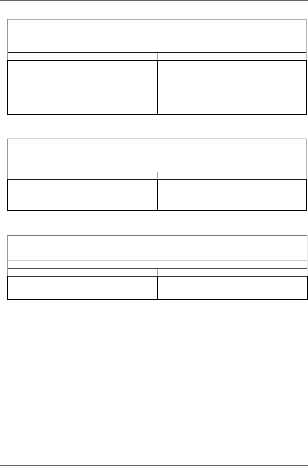
TX channel nominal frequencies
Band 10.30 – 10.59 GHz default duplex 168 MHz
Bandwidth: 14 MHz VO-R/14/12.2012-17 duplex range 70 – 273 MHz
( Freq.table: rcinfo10_A_default:6 )
Ch.No. Lower [MHz] Upper [MHz] Ch.No. Lower [MHz] Upper [MHz]
1 10308
2 10315 10483 6 10371 10539
3 10329 10497 7 10385 10553
4 10343 10511 8 10399 10567
5 10357 10525 9 10413 10581
6 10371 10539
7 10385 10553 ver. 2.0
RAy2-10 – xA
A sub-band
TX channel nominal frequencies
Band 10.30 – 10.59 GHz default duplex 168 MHz
Bandwidth: 28 MHz VO-R/14/12.2012-17 duplex range 84 – 252 MHz
( Freq.table: rcinfo10_A_default:6 )
Ch.No. Lower [MHz] Upper [MHz] Ch.No. Lower [MHz] Upper [MHz]
1 10322 10490 3 10378 10546
2 10350 10518 4 10406 10574
3 10378 10546
4 10406 10574 ver. 2.0
RAy2-10 – xA
A sub-band
TX channel nominal frequencies
Band 10.30 – 10.59 GHz default duplex 168 MHz
Bandwidth: 56 MHz
Channel arrangements based on 7 MHz channels
duplex range 112 – 224 MHz
( Freq.table: rcinfo10_A_default:6 )
Ch.No. Lower [MHz] Upper [MHz] Ch.No. Lower [MHz] Upper [MHz]
1 10336 10504 2 10392 10560
2 10392 10560
ver. 2.0
RAy2-10 – xA
A sub-band
183© RACOM s.r.o. – RAy2 Microwave Link
Technical parameters

10.3.4. Nominal frequencies, band 10.15 – 10.65 GHz
TX channel nominal frequencies
Band 10.15 – 10.65 GHz, duplex spacing 350 MHz
Bandwidth: 1.75 MHz Based on 3.5 MHz channels
( Freq.table: rcinfo10_B_default:5 )
Ch.No. Lower [MHz] Upper [MHz] Ch.No. Lower [MHz] Upper [MHz]
1 10151.375 10501.375 43 10224.875 10574.875
2 10153.125 10503.125 44 10226.625 10576.625
3 10154.875 10504.875 45 10228.375 10578.375
4 10156.625 10506.625 46 10230.125 10580.125
5 10158.375 10508.375 47 10231.875 10581.875
6 10160.125 10510.125 48 10233.625 10583.625
7 10161.875 10511.875 49 10235.375 10585.375
8 10163.625 10513.625 50 10237.125 10587.125
9 10165.375 10515.375 51 10238.875 10588.875
10 10167.125 10517.125 52 10240.625 10590.625
11 10168.875 10518.875 53 10242.375 10592.375
12 10170.625 10520.625 54 10244.125 10594.125
13 10172.375 10522.375 55 10245.875 10595.875
14 10174.125 10524.125 56 10247.625 10597.625
15 10175.875 10525.875 57 10249.375 10599.375
16 10177.625 10527.625 58 10251.125 10601.125
17 10179.375 10529.375 59 10252.875 10602.875
18 10181.125 10531.125 60 10254.625 10604.625
19 10182.875 10532.875 61 10256.375 10606.375
20 10184.625 10534.625 62 10258.125 10608.125
21 10186.375 10536.375 63 10259.875 10609.875
22 10188.125 10538.125 64 10261.625 10611.625
23 10189.875 10539.875 65 10263.375 10613.375
24 10191.625 10541.625 66 10265.125 10615.125
25 10193.375 10543.375 67 10266.875 10616.875
26 10195.125 10545.125 68 10268.625 10618.625
27 10196.875 10546.875 69 10270.375 10620.375
28 10198.625 10548.625 70 10272.125 10622.125
29 10200.375 10550.375 71 10273.875 10623.875
30 10202.125 10552.125 72 10275.625 10625.625
31 10203.875 10553.875 73 10277.375 10627.375
32 10205.625 10555.625 74 10279.125 10629.125
33 10207.375 10557.375 75 10280.875 10630.875
34 10209.125 10559.125 76 10282.625 10632.625
35 10210.875 10560.875 77 10284.375 10634.375
36 10212.625 10562.625 78 10286.125 10636.125
37 10214.375 10564.375 79 10287.875 10637.875
38 10216.125 10566.125 80 10289.625 10639.625
39 10217.875 10567.875 81 10291.375 10641.375
40 10219.625 10569.625 82 10293.125 10643.125
41 10221.375 10571.375 83 10294.875 10644.875
42 10223.125 10573.125 84 10296.625 10646.625
43 10224.875 10574.875
44 10226.625 10576.625 ver. 2.0
RAy2-10 - xB
B sub-band
RAy2 Microwave Link – © RACOM s.r.o.184
Technical parameters

TX channel nominal frequencies
Band 10.15 – 10.65 GHz, duplex spacing 350 MHz
Bandwidth: 3.5 MHz CEPT/ERC/REC 12-05 E
( Freq.table: rcinfo10_B_default:5 )
Ch.No. Lower [MHz] Upper [MHz] Ch.No. Lower [MHz] Upper [MHz]
1 10152.25 10502.25 22 10225.75 10575.75
2 10155.75 10505.75 23 10229.25 10579.25
3 10159.25 10509.25 24 10232.75 10582.75
4 10162.75 10512.75 25 10236.25 10586.25
5 10166.25 10516.25 26 10239.75 10589.75
6 10169.75 10519.75 27 10243.25 10593.25
7 10173.25 10523.25 28 10246.75 10596.75
8 10176.75 10526.75 29 10250.25 10600.25
9 10180.25 10530.25 30 10253.75 10603.75
10 10183.75 10533.75 31 10257.25 10607.25
11 10187.25 10537.25 32 10260.75 10610.75
12 10190.75 10540.75 33 10264.25 10614.25
13 10194.25 10544.25 34 10267.75 10617.75
14 10197.75 10547.75 35 10271.25 10621.25
15 10201.25 10551.25 36 10274.75 10624.75
16 10204.75 10554.75 37 10278.25 10628.25
17 10208.25 10558.25 38 10281.75 10631.75
18 10211.75 10561.75 39 10285.25 10635.25
19 10215.25 10565.25 40 10288.75 10638.75
20 10218.75 10568.75 41 10292.25 10642.25
21 10222.25 10572.25 42 10295.75 10645.75
22 10225.75 10575.75
23 10229.25 10579.25 ver. 2.0
RAy2-10 - xB
B sub-band
TX channel nominal frequencies
Band 10.15 – 10.65 GHz, duplex spacing 350 MHz
Bandwidth: 7 MHz CEPT/ERC/REC 12-05 E
( Freq.table: rcinfo10_B_default:5 )
Ch.No. Lower [MHz] Upper [MHz] Ch.No. Lower [MHz] Upper [MHz]
1 10157.5 10507.5 11 10227.5 10577.5
2 10164.5 10514.5 12 10234.5 10584.5
3 10171.5 10521.5 13 10241.5 10591.5
4 10178.5 10528.5 14 10248.5 10598.5
5 10185.5 10535.5 15 10255.5 10605.5
6 10192.5 10542.5 16 10262.5 10612.5
7 10199.5 10549.5 17 10269.5 10619.5
8 10206.5 10556.5 18 10276.5 10626.5
9 10213.5 10563.5 19 10283.5 10633.5
10 10220.5 10570.5 20 10290.5 10640.5
11 10228 10578
12 10235 10585 ver. 2.0
RAy2-10 - xB
B sub-band
185© RACOM s.r.o. – RAy2 Microwave Link
Technical parameters

TX channel nominal frequencies
Band 10.15 – 10.65 GHz, duplex spacing 350 MHz
Bandwidth: 14 MHz CEPT/ERC/REC 12-05 E + 7 MHz based channels
( Freq.table: rcinfo10_B_default:5 )
Ch.No. Lower [MHz] Upper [MHz] Ch.No. Lower [MHz] Upper [MHz]
1 10161 10511 6 10231 10581
1c 10168 10518 6c 10238 10588
2 10175 10525 7 10245 10595
2c 10182 10532 7c 10252 10602
3 10189 10539 8 10259 10609
3c 10196 10546 8c 10266 10616
4 10203 10553 9 10273 10623
4c 10210 10560 9c 10280 10630
5 10217 10567 10 10287 10637
5c 10224 10574
6
10231 10581
6c 10238 10588 ver. 2.0
RAy2-10 - xB
B sub-band
TX channel nominal frequencies
Band 10.15 – 10.65 GHz, duplex spacing 350 MHz
Bandwidth: 20 MHz
( Freq.table: rcinfo10_B_default:5 )
Ch.No. Lower [MHz] Upper [MHz] Ch.No. Lower [MHz] Upper [MHz]
1 10175 10525 4 10235 10585
2 10195 10545 5 10255 10605
3 10215 10565 6 10275 10625
4 10235 10585 0 0 0
5 10255 10605 ver. 1.0
RAy2-10 - xB
B sub-band
TX channel nominal frequencies
Band 10.15 – 10.65 GHz, duplex spacing 350 MHz
Bandwidth: 28 MHz CEPT/ERC/REC 12-05 E
( Freq.table: rcinfo10_B_default:5 )
Ch.No. Lower [MHz] Upper [MHz] Ch.No. Lower [MHz] Upper [MHz]
1 10168 10518 4 10252 10602
2 10196 10546 5 10280 10630
3 10224 10574
4 10252 10602
5 10280 10630 ver. 2.0
RAy2-10 - xB
B sub-band
RAy2 Microwave Link – © RACOM s.r.o.186
Technical parameters

TX channel nominal frequencies
Band 10.15 – 10.65 GHz, duplex spacing 350 MHz
Bandwidth: 56 MHz CEPT/ERC/REC 12-05 E
( Freq.table: rcinfo10_B_default:5 )
Ch.No. Lower [MHz] Upper [MHz] Ch.No. Lower [MHz] Upper [MHz]
1 10182 10532 3 10238 10588
2 10210 10560 4 10266 10616
3 10238 10588
4 10266 10616 ver. 2.0
RAy2-10 - xB
B sub-band
187© RACOM s.r.o. – RAy2 Microwave Link
Technical parameters
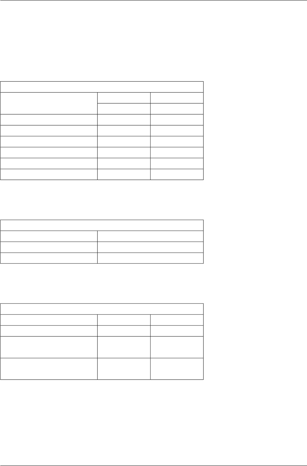
10.4. RAy2-11 A,B parameters
10.4.1. Upper/Lower Limits
TX powerRAy2-11-xA,RAy2-11-xB
MaxMin
Modulation [dBm][dBm]
24-15QPSK
22-1516-QAM
22-1532-QAM
21-1564-QAM
20-15128-QAM
19-15256-QAM
ver. 2.2
Duplex spacingRAy2-11-xA,RAy2-11-xB
[MHz]Sub-band
490, 530A
490, 530B
ver. 2.5
Sub-band RangeRAy2-11-xA,RAy2-11-xB
Unit UUnit LSub-band
[MHz][MHz]
11.18510.695min
A11.46010.970max
11.42510.935min
B11.69511.195max
ver. 1.0
RAy2 Microwave Link – © RACOM s.r.o.188
Technical parameters
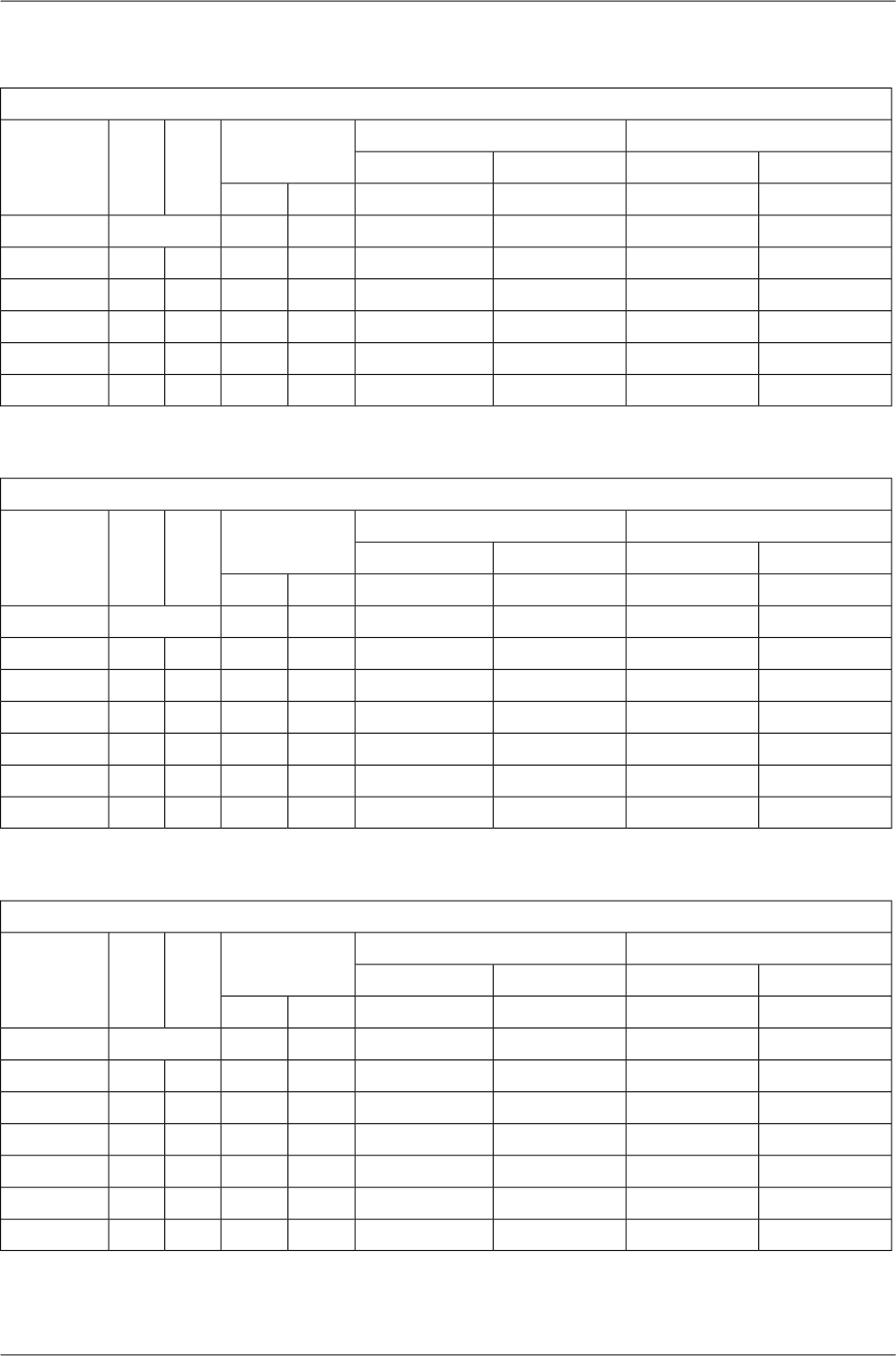
10.4.2. Radio parameters
Channel spacing 1.75 MHz; ACCP operationRAy2-11-xA, RAy2-11-xB
Adjacent channel SelectivityCo-channel rejection
RSS / SNR for
BER 10-6
User
Bit
Rate
Raw
Bit
Rate
Modula-
tion
3 dB1 dB3 dB1 dB
declared / limitdeclared / limitdeclared / limitdeclared / limitSNRRSS
[dB][dB][dB][dB][dB][dBm][Mbps][-]
-4/-140/-1219/1223/159.5-992.53.1QPSK
-7/-13-3/-1126.5/2030/2215.0-935.06.316-QAM
-7/-12-3/-1026.5/2230/2419.0-896.37.832-QAM
-7/-10-3/-926.5/2630/2920.5-887.49.464-QAM
-7/-7-3/-826.5/2830/3023.5-848.911.0128-QAM
ver. 2.3
Channel spacing 3.5 MHz; ACCP operationRAy2-11-xA, RAy2-11-xB
Adjacent channel SelectivityCo-channel rejection
RSS / SNR for
BER 10-6
User
Bit
Rate
Raw
Bit
Rate
Modula-
tion
3 dB1 dB3 dB1 dB
declared / limitdeclared / limitdeclared / limitdeclared / limitSNRRSS
[dB][dB][dB][dB][dB][dBm][Mbps][-]
-4/-160/-1419/1223/159.5-974.96QPSK
-7/-15-3/-1326.5/2030/2215.0-909.61216-QAM
-7/-14-3/-1226.5/2230/2418.5-8712.11532-QAM
-7/-12-3/-1126.5/2630/2920.5-8414.31864-QAM
-7/-8-3/-926.5/2830/3023.5-8117.221128-QAM
-7/-7-3/-526.5/3130/3326.0-7919.724256-QAM
ver. 2.2
Channel spacing 7 MHz; ACCP operationRAy2-11-xA, RAy2-11-xB
Adjacent channel SelectivityCo-channel rejection
RSS / SNR for
BER 10-6
User
Bit
Rate
Raw
Bit
Rate
Modula-
tion
3 dB1 dB3 dB1 dB
declared / limitdeclared / limitdeclared / limitdeclared / limitSNRRSS
[dB][dB][dB][dB][dB][dBm][Mbps][-]
-4/-220/-2019/1223/158.5-958.512QPSK
-7/-19-3/-1826.5/2030/2215.0-8817.22416-QAM
-7/-18-3/-1626.5/2230/2418.5-8522.13032-QAM
-7/-16-3/-1430/2634/2921.5-8129.73664-QAM
-6/-14-2/-1233/3037/3225.0-7934.742128-QAM
-4/-120/-1036/3140/3326.0-7640.749256-QAM
ver. 2.4
189© RACOM s.r.o. – RAy2 Microwave Link
Technical parameters

Channel spacing 14 MHz; ACCP operationRAy2-11-xA, RAy2-11-xB
Adjacent channel SelectivityCo-channel rejection
RSS / SNR for
BER 10-6
User
Bit
Rate
Raw
Bit
Rate
Modula-
tion
3 dB1 dB3 dB1 dB
declared / limitdeclared / limitdeclared / limitdeclared / limitSNRRSS
[dB][dB][dB][dB][dB][dBm][Mbps][-]
-4/-230/-2119/1223/148.5-9319.924QPSK
-7/-21-3/-1926.5/1830/2015.0-8638.84816-QAM
-9/-19-5/-1729/2333/2618.5-8249.16032-QAM
-7/-17-3/-1430/2634/2821.5-7962.37264-QAM
-6/-14-2/-1233/2837/3025.0-7573.684128-QAM
-4/-120/-1036/3140/3328.0-7381.296256-QAM
ver. 2.2
Channel spacing 28 / 30 MHz; ACCP operationRAy2-11-xA, RAy2-11-xB
Adjacent channel SelectivityCo-channel rejection
RSS / SNR for
BER 10-6
User
Bit
Rate
Raw
Bit
Rate
Modula-
tion
3 dB1 dB3 dB1 dB
declared / limitdeclared / limitdeclared / limitdeclared / limitSNRRSS
[dB][dB][dB][dB][dB][dBm][Mbps][-]
-4/-230/-2119/1023/127.5-9136.850QPSK
-7/-20-3/-1826.5/1830/2015.0-8380.910016-QAM
-9/-19-5/-1629/2233/2418.5-79102.412532-QAM
-7/-15-3/-1230/2634/2821.5-76129.815064-QAM
-8/-12-5/-932/2835/3025.0-72155.5175128QAM
-4/-90/-636/3140/3326.5-70170.7200256-QAM
ver. 2.1
Channel spacing 28 / 30 MHz; ACAP operationRAy2-11-xA, RAy2-11-xB
Adjacent channel SelectivityCo-channel rejection
RSS / SNR for
BER 10-6
User
Bit
Rate
Raw
Bit
Rate
Modula-
tion
3 dB1 dB3 dB1 dB
declared / limitdeclared / limitdeclared / limitdeclared / limitSNRRSS
[dB][dB][dB][dB][dB][dBm][Mbps][-]
-4/-170/-1519/1023/127.5-89.538.352QPSK
-7/-14-3/-1226.5/1830/2015.0-82.584.110416-QAM
-9/-13-5/-1029/2233/2418.5-78.5106.413032-QAM
1/-94/-630/2634/2821.5-75.5135.015664-QAM
7/-610/-336/2840/3025.0-71.5161.7182128QAM
6/-310/039/3143/3326.5-68.5185.2208256-QAM
ver. 2.2
RAy2 Microwave Link – © RACOM s.r.o.190
Technical parameters

Channel spacing 40 MHz; ACCP operationRAy2-11-xA, RAy2-11-xB
Adjacent channel SelectivityCo-channel rejection
RSS / SNR for
BER 10-6
User
Bit
Rate
Raw
Bit
Rate
Modula-
tion
3 dB1 dB3 dB1 dB
declared / limitdeclared / limitdeclared / limitdeclared / limitSNRRSS
[dB][dB][dB][dB][dB][dBm][Mbps][-]
-8/-24-4/-2229/1033/127.5-8850.168QPSK.
-8/-21-4/-1829/1733/1915.0-81110.013616-QAM
-8/-19-4/-1629/2133/2418.5-77139.217032-QAM
-8/-16-4/-1429/2533/2721.5-74176.520464-QAM
-8/-12-4/-1033/2837/3025.0-70211.4238128QAM
-4/-100/-836/3040/3326.5-68232.1272256-QAM
ver. 2.1
Channel spacing 56 MHz; ACCP operationRAy2-11-xA, RAy2-11-xB
Adjacent channel SelectivityCo-channel rejection
RSS / SNR for
BER 10-6
User
Bit
Rate
Raw
Bit
Rate
Modula-
tion
3 dB1 dB3 dB1 dB
declared / limitdeclared / limitdeclared / limitdeclared / limitSNRRSS
[dB][dB][dB][dB][dB][dBm][Mbps][-]
-4/-280/-2619/1023/127.5-8772.999QPSK
-7/-21-3/-1926.5/1730/1915.0-80160.219816-QAM
-9/-17-5/-1529/2233/2418.5-76202.7247.532-QAM
1/-164/-1430/2534/2721.5-73256.929764-QAM
-1/-123/-1033/2837/3025.0-69303.7346.5128QAM
7/-1010/-836/3040/3326.5-67337.7396256-QAM
ver. 2.1
Channel spacing 56 MHz TO; ACCP operationRAy2-11-xA, RAy2-11-xB
Adjacent channel SelectivityCo-channel rejection
RSS / SNR for
BER 10-6
User
Bit
Rate
Raw
Bit
Rate
Modula-
tion
3 dB1 dB3 dB1 dB
declared / limitdeclared / limitdeclared / limitdeclared / limitSNRRSS
[dB][dB][dB][dB][dB][dBm][Mbps][-]
-4/-260/-2419/1123/1310.0-8585.899QPSK
-7/-20-3/-1826.5/1830/2016.0-78169.919816-QAM
-9/-15-5/-1429/2333/2519.0-74206.2247.532-QAM
1/-114/-930/2634/2922.5-70268.129764-QAM
-8/-10-5/-832/2935/3225.5-67309.0346.5128QAM
-4/-80/-739/3243/3527.5-64358.9396256-QAM
ver. 2.2
191© RACOM s.r.o. – RAy2 Microwave Link
Technical parameters

10.4.3. Nominal frequencies, duplex 490 MHz
RAy2-11 - xA, RAy2-11 - xB TX channel nominal frequencies
Band 10.7 – 11.7 GHz, duplex spacing 490 MHz
Bandwidth: 1.75 MHz Channel arrangements based on 28 MHz channels
( Freq. table: rcinfo11_A_490_default:13 ) ( Freq. table: rcinfo11_B_490_default:13 )
Ch.No. Lower [MHz] Upper [MHz] Ch.No. Lower [MHz] Upper [MHz] Ch.No. Lower [MHz] Upper [MHz] Ch.No. Lower [MHz] Upper [MHz]
1 10709.875 11199.875 76 10841.125 11331.125 131 10937.375 11427.375 206 11068.625 11558.625
2 10711.625 11201.625 77 10842.875 11332.875 132 10939.125 11429.125 207 11070.375 11560.375
3 10713.375 11203.375 78 10844.625 11334.625 133 10940.875 11430.875 208 11072.125 11562.125
4 10715.125 11205.125 79 10846.375 11336.375 134 10942.625 11432.625 209 11073.875 11563.875
5 10716.875 11206.875 80 10848.125 11338.125 135 10944.375 11434.375 210 11075.625 11565.625
6 10718.625 11208.625 81 10849.875 11339.875 136 10946.125 11436.125 211 11077.375 11567.375
7 10720.375 11210.375 82 10851.625 11341.625 137 10947.875 11437.875 212 11079.125 11569.125
8 10722.125 11212.125 83 10853.375 11343.375 138 10949.625 11439.625 213 11080.875 11570.875
9 10723.875 11213.875 84 10855.125 11345.125 139 10951.375 11441.375 214 11082.625 11572.625
10 10725.625 11215.625 85 10856.875 11346.875 140 10953.125 11443.125 215 11084.375 11574.375
11 10727.375 11217.375 86 10858.625 11348.625 141 10954.875 11444.875 216 11086.125 11576.125
12 10729.125 11219.125 87 10860.375 11350.375 142 10956.625 11446.625 217 11087.875 11577.875
13 10730.875 11220.875 88 10862.125 11352.125 143 10958.375 11448.375 218 11089.625 11579.625
14 10732.625 11222.625 89 10863.875 11353.875 144 10960.125 11450.125 219 11091.375 11581.375
15 10734.375 11224.375 90 10865.625 11355.625 145 10961.875 11451.875 220 11093.125 11583.125
16 10736.125 11226.125 91 10867.375 11357.375 146 10963.625 11453.625 221 11094.875 11584.875
17 10737.875 11227.875 92 10869.125 11359.125 147 10965.375 11455.375 222 11096.625 11586.625
18 10739.625 11229.625 93 10870.875 11360.875 148 10967.125 11457.125 223 11098.375 11588.375
19 10741.375 11231.375 94 10872.625 11362.625 149 10968.875 11458.875 224 11100.125 11590.125
20 10743.125 11233.125 95 10874.375 11364.375 150 10970.625 11460.625 225 11101.875 11591.875
21 10744.875 11234.875 96 10876.125 11366.125 151 10972.375 11462.375 226 11103.625 11593.625
22 10746.625 11236.625 97 10877.875 11367.875 152 10974.125 11464.125 227 11105.375 11595.375
23 10748.375 11238.375 98 10879.625 11369.625 153 10975.875 11465.875 228 11107.125 11597.125
24 10750.125 11240.125 99 10881.375 11371.375 154 10977.625 11467.625 229 11108.875 11598.875
25 10751.875 11241.875 100 10883.125 11373.125 155 10979.375 11469.375 230 11110.625 11600.625
26 10753.625 11243.625 101 10884.875 11374.875 156 10981.125 11471.125 231 11112.375 11602.375
27 10755.375 11245.375 102 10886.625 11376.625 157 10982.875 11472.875 232 11114.125 11604.125
28 10757.125 11247.125 103 10888.375 11378.375 158 10984.625 11474.625 233 11115.875 11605.875
29 10758.875 11248.875 104 10890.125 11380.125 159 10986.375 11476.375 234 11117.625 11607.625
30 10760.625 11250.625 105 10891.875 11381.875 160 10988.125 11478.125 235 11119.375 11609.375
31 10762.375 11252.375 106 10893.625 11383.625 161 10989.875 11479.875 236 11121.125 11611.125
32 10764.125 11254.125 107 10895.375 11385.375 162 10991.625 11481.625 237 11122.875 11612.875
33 10765.875 11255.875 108 10897.125 11387.125 163 10993.375 11483.375 238 11124.625 11614.625
34 10767.625 11257.625 109 10898.875 11388.875 164 10995.125 11485.125 239 11126.375 11616.375
35 10769.375 11259.375 110 10900.625 11390.625 165 10996.875 11486.875 240 11128.125 11618.125
36 10771.125 11261.125 111 10902.375 11392.375 166 10998.625 11488.625 241 11129.875 11619.875
37 10772.875 11262.875 112 10904.125 11394.125 167 11000.375 11490.375 242 11131.625 11621.625
38 10774.625 11264.625 113 10905.875 11395.875 168 11002.125 11492.125 243 11133.375 11623.375
39 10776.375 11266.375 114 10907.625 11397.625 169 11003.875 11493.875 244 11135.125 11625.125
40 10778.125 11268.125 115 10909.375 11399.375 170 11005.625 11495.625 245 11136.875 11626.875
41 10779.875 11269.875 116 10911.125 11401.125 171 11007.375 11497.375 246 11138.625 11628.625
42 10781.625 11271.625 117 10912.875 11402.875 172 11009.125 11499.125 247 11140.375 11630.375
43 10783.375 11273.375 118 10914.625 11404.625 173 11010.875 11500.875 248 11142.125 11632.125
44 10785.125 11275.125 119 10916.375 11406.375 174 11012.625 11502.625 249 11143.875 11633.875
45 10786.875 11276.875 120 10918.125 11408.125 175 11014.375 11504.375 250 11145.625 11635.625
46 10788.625 11278.625 121 10919.875 11409.875 176 11016.125 11506.125 251 11147.375 11637.375
47 10790.375 11280.375 122 10921.625 11411.625 177 11017.875 11507.875 252 11149.125 11639.125
48 10792.125 11282.125 123 10923.375 11413.375 178 11019.625 11509.625 253 11150.875 11640.875
49 10793.875 11283.875 124 10925.125 11415.125 179 11021.375 11511.375 254 11152.625 11642.625
50 10795.625 11285.625 125 10926.875 11416.875 180 11023.125 11513.125 255 11154.375 11644.375
51 10797.375 11287.375 126 10928.625 11418.625 181 11024.875 11514.875 256 11156.125 11646.125
52 10799.125 11289.125 127 10930.375 11420.375 182 11026.625 11516.625 257 11157.875 11647.875
53 10800.875 11290.875 128 10932.125 11422.125 183 11028.375 11518.375 258 11159.625 11649.625
54 10802.625 11292.625 129 10933.875 11423.875 184 11030.125 11520.125 259 11161.375 11651.375
55 10804.375 11294.375 130 10935.625 11425.625 185 11031.875 11521.875 260 11163.125 11653.125
56 10806.125 11296.125 131 10937.375 11427.375 186 11033.625 11523.625 261 11164.875 11654.875
57 10807.875 11297.875 132 10939.125 11429.125 187 11035.375 11525.375 262 11166.625 11656.625
58 10809.625 11299.625 133 10940.875 11430.875 188 11037.125 11527.125 263 11168.375 11658.375
59 10811.375 11301.375 134 10942.625 11432.625 189 11038.875 11528.875 264 11170.125 11660.125
60 10813.125 11303.125 135 10944.375 11434.375 190 11040.625 11530.625 265 11171.875 11661.875
61 10814.875 11304.875 136 10946.125 11436.125 191 11042.375 11532.375 266 11173.625 11663.625
62 10816.625 11306.625 137 10947.875 11437.875 192 11044.125 11534.125 267 11175.375 11665.375
63 10818.375 11308.375 138 10949.625 11439.625 193 11045.875 11535.875 268 11177.125 11667.125
64 10820.125 11310.125 139 10951.375 11441.375 194 11047.625 11537.625 269 11178.875 11668.875
65 10821.875 11311.875 140 10953.125 11443.125 195 11049.375 11539.375 270 11180.625 11670.625
66 10823.625 11313.625 141 10954.875 11444.875 196 11051.125 11541.125 271 11182.375 11672.375
67 10825.375 11315.375 142 10956.625 11446.625 197 11052.875 11542.875 272 11184.125 11674.125
68 10827.125 11317.125 143 10958.375 11448.375 198 11054.625 11544.625
69 10828.875 11318.875 144 10960.125 11450.125 199 11056.375 11546.375
70 10830.625 11320.625 145 10961.875 11451.875 200 11058.125 11548.125
71 10832.375 11322.375 146 10963.625 11453.625 201 11059.875 11549.875
72 10834.125 11324.125 147 10965.375 11455.375 202 11061.625 11551.625
73 10835.875 11325.875 148 10967.125 11457.125 203 11063.375 11553.375
74 10837.625 11327.625 149 10968.875 11458.875 204 11065.125 11555.125
75 10839.375 11329.375 205 11066.875 11556.875
76 10841.13 11331.13 206 11068.63 11558.63
77 10842.88 11332.88 207 11070.38 11560.38 ver. 2.2
A sub-band
B sub-band
RAy2 Microwave Link – © RACOM s.r.o.192
Technical parameters

RAy2-11 - xA, RAy2-11 - xB TX channel nominal frequencies
Band 10.7 – 11.7 GHz, duplex spacing 490 MHz
Bandwidth: 3.5 MHz Channel arrangements based on 28 MHz channels
( Freq. table: rcinfo11_A_490_default:13 ) ( Freq. table: rcinfo11_B_490_default:13 )
Ch.No. Lower [MHz] Upper [MHz] Ch.No. Lower [MHz] Upper [MHz] Ch.No. Lower [MHz] Upper [MHz] Ch.No. Lower [MHz] Upper [MHz]
1 10710.75 11200.75 38 10840.25 11330.25 66 10938.25 11428.25 103 11067.75 11557.75
2 10714.25 11204.25 39 10843.75 11333.75 67 10941.75 11431.75 104 11071.25 11561.25
3 10717.75 11207.75 40 10847.25 11337.25 68 10945.25 11435.25 105 11074.75 11564.75
4 10721.25 11211.25 41 10850.75 11340.75 69 10948.75 11438.75 106 11078.25 11568.25
5 10724.75 11214.75 42 10854.25 11344.25 70 10952.25 11442.25 107 11081.75 11571.75
6 10728.25 11218.25 43 10857.75 11347.75 71 10955.75 11445.75 108 11085.25 11575.25
7 10731.75 11221.75 44 10861.25 11351.25 72 10959.25 11449.25 109 11088.75 11578.75
8 10735.25 11225.25 45 10864.75 11354.75 73 10962.75 11452.75 110 11092.25 11582.25
9 10738.75 11228.75 46 10868.25 11358.25 74 10966.25 11456.25 111 11095.75 11585.75
10 10742.25 11232.25 47 10871.75 11361.75 75 10969.75 11459.75 112 11099.25 11589.25
11 10745.75 11235.75 48 10875.25 11365.25 76 10973.25 11463.25 113 11102.75 11592.75
12 10749.25 11239.25 49 10878.75 11368.75 77 10976.75 11466.75 114 11106.25 11596.25
13 10752.75 11242.75 50 10882.25 11372.25 78 10980.25 11470.25 115 11109.75 11599.75
14 10756.25 11246.25 51 10885.75 11375.75 79 10983.75 11473.75 116 11113.25 11603.25
15 10759.75 11249.75 52 10889.25 11379.25 80 10987.25 11477.25 117 11116.75 11606.75
16 10763.25 11253.25 53 10892.75 11382.75 81 10990.75 11480.75 118 11120.25 11610.25
17 10766.75 11256.75 54 10896.25 11386.25 82 10994.25 11484.25 119 11123.75 11613.75
18 10770.25 11260.25 55 10899.75 11389.75 83 10997.75 11487.75 120 11127.25 11617.25
19 10773.75 11263.75 56 10903.25 11393.25 84 11001.25 11491.25 121 11130.75 11620.75
20 10777.25 11267.25 57 10906.75 11396.75 85 11004.75 11494.75 122 11134.25 11624.25
21 10780.75 11270.75 58 10910.25 11400.25 86 11008.25 11498.25 123 11137.75 11627.75
22 10784.25 11274.25 59 10913.75 11403.75 87 11011.75 11501.75 124 11141.25 11631.25
23 10787.75 11277.75 60 10917.25 11407.25 88 11015.25 11505.25 125 11144.75 11634.75
24 10791.25 11281.25 61 10920.75 11410.75 89 11018.75 11508.75 126 11148.25 11638.25
25 10794.75 11284.75 62 10924.25 11414.25 90 11022.25 11512.25 127 11151.75 11641.75
26 10798.25 11288.25 63 10927.75 11417.75 91 11025.75 11515.75 128 11155.25 11645.25
27 10801.75 11291.75 64 10931.25 11421.25 92 11029.25 11519.25 129 11158.75 11648.75
28 10805.25 11295.25 65 10934.75 11424.75 93 11032.75 11522.75 130 11162.25 11652.25
29 10808.75 11298.75 66 10938.25 11428.25 94 11036.25 11526.25 131 11165.75 11655.75
30 10812.25 11302.25 67 10941.75 11431.75 95 11039.75 11529.75 132 11169.25 11659.25
31 10815.75 11305.75 68 10945.25 11435.25 96 11043.25 11533.25 133 11172.75 11662.75
32 10819.25 11309.25 69 10948.75 11438.75 97 11046.75 11536.75 134 11176.25 11666.25
33 10822.75 11312.75 70 10952.25 11442.25 98 11050.25 11540.25 135 11179.75 11669.75
34 10826.25 11316.25 71 10955.75 11445.75 99 11053.75 11543.75 136 11183.25 11673.25
35 10829.75 11319.75 72 10959.25 11449.25 100 11057.25 11547.25
36 10833.25 11323.25 73 10962.75 11452.75 101 11060.75 11550.75
37 10836.75 11326.75 74 10966.25 11456.25 102 11064.25 11554.25
38 10840.25 11330.25 103 11067.75 11557.75
39 10843.75 11333.75 104 11071.25 11561.25 ver. 2.2
A sub-band
B sub-band
193© RACOM s.r.o. – RAy2 Microwave Link
Technical parameters

TX channel nominal frequencies
Band 10.7 – 11.7 GHz, duplex spacing 490 MHz
Bandwidth: 7 MHz Channel arrangements based on 28 MHz channels
( Freq. table: rcinfo11_A_490_default:14 ) ( Freq. table: rcinfo11_B_490_default:14 )
Ch.No. Lower [MHz] Upper [MHz] Ch.No. Lower [MHz] Upper [MHz]
33
1 10712.5 11202.5 34 10943.5 11433.5
2 10719.5 11209.5 35 10950.5 11440.5
3 10726.5 11216.5 36 10957.5 11447.5
4 10733.5 11223.5 37 10964.5 11454.5
5 10740.5 11230.5 38 10971.5 11461.5
6 10747.5 11237.5 39 10978.5 11468.5
7 10754.5 11244.5 40 10985.5 11475.5
8 10761.5 11251.5 41 10992.5 11482.5
9 10768.5 11258.5 42 10999.5 11489.5
10 10775.5 11265.5 43 11006.5 11496.5
11 10782.5 11272.5 44 11013.5 11503.5
12 10789.5 11279.5 45 11020.5 11510.5
13 10796.5 11286.5 46 11027.5 11517.5
14 10803.5 11293.5 47 11034.5 11524.5
15 10810.5 11300.5 48 11041.5 11531.5
16 10817.5 11307.5 49 11048.5 11538.5
17 10824.5 11314.5 50 11055.5 11545.5
18 10831.5 11321.5 51 11062.5 11552.5
19 10838.5 11328.5 52 11069.5 11559.5
20 10845.5 11335.5 53 11076.5 11566.5
21 10852.5 11342.5 54 11083.5 11573.5
22 10859.5 11349.5 55 11090.5 11580.5
23 10866.5 11356.5 56 11097.5 11587.5
24 10873.5 11363.5 57 11104.5 11594.5
25 10880.5 11370.5 58 11111.5 11601.5
26 10887.5 11377.5 59 11118.5 11608.5
27 10894.5 11384.5 60 11125.5 11615.5
28 10901.5 11391.5 61 11132.5 11622.5
29 10908.5 11398.5 62 11139.5 11629.5
30 10915.5 11405.5 63 11146.5 11636.5
31 10922.5 11412.5 64 11153.5 11643.5
32 10929.5 11419.5 65 11160.5 11650.5
33 10936.5 11426.5 66 11167.5 11657.5
34 10943.5 11433.5 67 11174.5 11664.5
35 10950.5 11440.5 68 11181.5 11671.5
36 10957.5 11447.5
37 10964.5 11454.5
ver. 2.3
RAy2-11 - xA, RAy2-11 - xB
A sub-band B sub-band
RAy2 Microwave Link – © RACOM s.r.o.194
Technical parameters

TX channel nominal frequencies
Band 10.7 – 11.7 GHz, duplex spacing 490 MHz
Bandwidth: 14 MHz Channel arrangements based on 28 MHz channels
( Freq. table: rcinfo11_A_490_default:13 ) ( Freq. table: rcinfo11_B_490_default:13 )
Ch.No. Lower [MHz] Upper [MHz] Ch.No. Lower [MHz] Upper [MHz]
17
1 10716 11206 18 10954 11444
2 10730 11220 19 10968 11458
3 10744 11234 20 10982 11472
4 10758 11248 21 10996 11486
5 10772 11262 22 11010 11500
6 10786 11276 23 11024 11514
7 10800 11290 24 11038 11528
8 10814 11304 25 11052 11542
9 10828 11318 26 11066 11556
10 10842 11332 27 11080 11570
11 10856 11346 28 11094 11584
12 10870 11360 29 11108 11598
13 10884 11374 30 11122 11612
14 10898 11388 31 11136 11626
15 10912 11402 32 11150 11640
16 10926 11416 33 11164 11654
17 10940 11430 34 11178 11668
18 10954 11444
ver. 2.2
RAy2-11 - xA, RAy2-11 - xB
A sub-band B sub-band
TX channel nominal frequencies
Band 10.7 – 11.7 GHz, duplex spacing 490 MHz
Bandwidth: 28 MHz CEPT Rec. 12-06, Annex B.2
( Freq. table: rcinfo11_A_490_default:13 ) ( Freq. table: rcinfo11_B_490_default:13 )
Ch.No. Lower [MHz] Upper [MHz] Ch.No. Lower [MHz] Upper [MHz]
9
1 10723 11213 10 10975 11465
2 10751 11241 11 11003 11493
3 10779 11269 12 11031 11521
4 10807 11297 13 11059 11549
5 10835 11325 14 11087 11577
6 10863 11353 15 11115 11605
7 10891 11381 16 11143 11633
8 10919 11409 17 11171 11661
9 10947 11437
ver. 2.2
RAy2-11 - xA, RAy2-11 - xB
A sub-band B sub-band
195© RACOM s.r.o. – RAy2 Microwave Link
Technical parameters

TX channel nominal frequencies
Band 10.7 – 11.7 GHz, duplex spacing 490 MHz
Bandwidth: 30 MHz IC
( Freq. table: rcinfo11_A_490_default:13 ) ( Freq. table: rcinfo11_B_490_default:13 )
Ch.No. Lower [MHz] Upper [MHz] Ch.No. Lower [MHz] Upper [MHz]
8
1 10725 11215 9 10965 11455
2 10755 11245 10 10995 11485
3 10785 11275 11 11025 11515
4 10815 11305 12 11055 11545
5 10845 11335 13 11085 11575
6 10875 11365 14 11115 11605
7 10905 11395 15 11145 11635
8 10935 11425 16 11175 11665
ver. 1.1
RAy2-11 - xA, RAy2-11 - xB
A sub-band B sub-band
TX channel nominal frequencies
Band 10.7 – 11.7 GHz, duplex spacing 490 MHz
Bandwidth: 40 MHz (CEPT) CEPT 12-06 Annex B.1, ITU-R F.387 rec.1.2
( Freq. table: rcinfo11_A_490_default:13 ) ( Freq. table: rcinfo11_B_490_default:13 )
Ch.No. Lower [MHz] Upper [MHz] Ch.No. Lower [MHz] Upper [MHz]
6
1 10735 11225 7 10975 11465
2 10775 11265 8 11015 11505
3 10815 11305 9 11055 11545
4 10855 11345 10 11095 11585
5 10895 11385 11 11135 11625
6 10935 11425 12 11175 11665
ver. 1.3
RAy2-11 - xA, RAy2-11 - xB
A sub-band B sub-band
TX channel nominal frequencies
Band 10.7 – 11.7 GHz, duplex spacing 490 MHz
Bandwidth: 40 MHz (ACMA) ACMA
( Freq. table: rcinfo11_A_490_default:13 ) ( Freq. table: rcinfo11_B_490_default:13 )
Ch.No. Lower [MHz] Upper [MHz] Ch.No. Lower [MHz] Upper [MHz]
6
1 10715 11205 7 10955 11445
2 10755 11245 8 10995 11485
3 10795 11285 9 11035 11525
4 10835 11325 10 11075 11565
5 10875 11365 11 11115 11605
6 10915 11405 12 11155 11645
ver. 1.2
RAy2-11 - xA, RAy2-11 - xB
A sub-band B sub-band
RAy2 Microwave Link – © RACOM s.r.o.196
Technical parameters

TX channel nominal frequencies
Band 10.7 – 11.7 GHz, duplex spacing 490 MHz
Bandwidth: 56 MHz CEPT 12-06, Annex C
( Freq. table: rcinfo11_A_490_default:13 ) ( Freq. table: rcinfo11_B_490_default:13 )
Ch.No. Lower [MHz] Upper [MHz] Ch.No. Lower [MHz] Upper [MHz]
9
1 10737 11227 10 10989 11479
2 10765 11255 11 11017 11507
3 10793 11283 12 11045 11535
4 10821 11311 13 11073 11563
5 10849 11339 14 11101 11591
6 10877 11367 15 11129 11619
7 10905 11395 16 11157 11647
8 10933 11423
ver. 2.2
RAy2-11 - xA, RAy2-11 - xB
A sub-band B sub-band
TX channel nominal frequencies
Band 10.7 – 11.7 GHz, duplex spacing 490 MHz
Bandwidth: 56 (CS 80) MHz CEPT 12-06, Annex C
( Freq. table: rcinfo11_A_490_default:13 ) ( Freq. table: rcinfo11_B_490_default:13 )
Ch.No. Lower [MHz] Upper [MHz] Ch.No. Lower [MHz] Upper [MHz]
6
1 10755 11245 7 10995 11485
2 10795 11285 8 11035 11525
3 10835 11325 9 11075 11565
4 10875 11365 10 11115 11605
5 10915 11405 11 11155 11645
ver. 1.1
RAy2-11 - xA, RAy2-11 - xB
A sub-band B sub-band
197© RACOM s.r.o. – RAy2 Microwave Link
Technical parameters

10.4.4. Nominal frequencies, duplex 530 MHz
TX channel nominal frequencies
Band 10.7 – 11.7 GHz, duplex spacing 530 MHz
Bandwidth: 1.75 MHz Channel arrangements based on 28 MHz channels
( Freq. table: rcinfo11_A_530:13 ) ( Freq. table: rcinfo11_B_530:13 )
Ch.No. Lower [MHz] Upper [MHz] Ch.No. Lower [MHz] Upper [MHz] Ch.No. Lower [MHz] Upper [MHz] Ch.No. Lower [MHz] Upper [MHz]
1 10709.875 11239.875 64 10820.125 11350.125 131 10937.375 11467.375 196 11051.125 11581.125
2 10711.625 11241.625 65 10821.875 11351.875 132 10939.125 11469.125 197 11052.875 11582.875
3 10713.375 11243.375 66 10823.625 11353.625 133 10940.875 11470.875 198 11054.625 11584.625
4 10715.125 11245.125 67 10825.375 11355.375 134 10942.625 11472.625 199 11056.375 11586.375
5 10716.875 11246.875 68 10827.125 11357.125 135 10944.375 11474.375 200 11058.125 11588.125
6 10718.625 11248.625 69 10828.875 11358.875 136 10946.125 11476.125 201 11059.875 11589.875
7 10720.375 11250.375 70 10830.625 11360.625 137 10947.875 11477.875 202 11061.625 11591.625
8 10722.125 11252.125 71 10832.375 11362.375 138 10949.625 11479.625 203 11063.375 11593.375
9 10723.875 11253.875 72 10834.125 11364.125 139 10951.375 11481.375 204 11065.125 11595.125
10 10725.625 11255.625 73 10835.875 11365.875 140 10953.125 11483.125 205 11066.875 11596.875
11 10727.375 11257.375 74 10837.625 11367.625 141 10954.875 11484.875 206 11068.625 11598.625
12 10729.125 11259.125 75 10839.375 11369.375 142 10956.625 11486.625 207 11070.375 11600.375
13 10730.875 11260.875 76 10841.125 11371.125 143 10958.375 11488.375 208 11072.125 11602.125
14 10732.625 11262.625 77 10842.875 11372.875 144 10960.125 11490.125 209 11073.875 11603.875
15 10734.375 11264.375 78 10844.625 11374.625 145 10961.875 11491.875 210 11075.625 11605.625
16 10736.125 11266.125 79 10846.375 11376.375 146 10963.625 11493.625 211 11077.375 11607.375
17 10737.875 11267.875 80 10848.125 11378.125 147 10965.375 11495.375 212 11079.125 11609.125
18 10739.625 11269.625 81 10849.875 11379.875 148 10967.125 11497.125 213 11080.875 11610.875
19 10741.375 11271.375 82 10851.625 11381.625 149 10968.875 11498.875 214 11082.625 11612.625
20 10743.125 11273.125 83 10853.375 11383.375 150 10970.625 11500.625 215 11084.375 11614.375
21 10744.875 11274.875 84 10855.125 11385.125 151 10972.375 11502.375 216 11086.125 11616.125
22 10746.625 11276.625 85 10856.875 11386.875 152 10974.125 11504.125 217 11087.875 11617.875
23 10748.375 11278.375 86 10858.625 11388.625 153 10975.875 11505.875 218 11089.625 11619.625
24 10750.125 11280.125 87 10860.375 11390.375 154 10977.625 11507.625 219 11091.375 11621.375
25 10751.875 11281.875 88 10862.125 11392.125 155 10979.375 11509.375 220 11093.125 11623.125
26 10753.625 11283.625 89 10863.875 11393.875 156 10981.125 11511.125 221 11094.875 11624.875
27 10755.375 11285.375 90 10865.625 11395.625 157 10982.875 11512.875 222 11096.625 11626.625
28 10757.125 11287.125 91 10867.375 11397.375 158 10984.625 11514.625 223 11098.375 11628.375
29 10758.875 11288.875 92 10869.125 11399.125 159 10986.375 11516.375 224 11100.125 11630.125
30 10760.625 11290.625 93 10870.875 11400.875 160 10988.125 11518.125 225 11101.875 11631.875
31 10762.375 11292.375 94 10872.625 11402.625 161 10989.875 11519.875 226 11103.625 11633.625
32 10764.125 11294.125 95 10874.375 11404.375 162 10991.625 11521.625 227 11105.375 11635.375
33 10765.875 11295.875 96 10876.125 11406.125 163 10993.375 11523.375 228 11107.125 11637.125
34 10767.625 11297.625 97 10877.875 11407.875 164 10995.125 11525.125 229 11108.875 11638.875
35 10769.375 11299.375 98 10879.625 11409.625 165 10996.875 11526.875 230 11110.625 11640.625
36 10771.125 11301.125 99 10881.375 11411.375 166 10998.625 11528.625 231 11112.375 11642.375
37 10772.875 11302.875 100 10883.125 11413.125 167 11000.375 11530.375 232 11114.125 11644.125
38 10774.625 11304.625 101 10884.875 11414.875 168 11002.125 11532.125 233 11115.875 11645.875
39 10776.375 11306.375 102 10886.625 11416.625 169 11003.875 11533.875 234 11117.625 11647.625
40 10778.125 11308.125 103 10888.375 11418.375 170 11005.625 11535.625 235 11119.375 11649.375
41 10779.875 11309.875 104 10890.125 11420.125 171 11007.375 11537.375 236 11121.125 11651.125
42 10781.625 11311.625 105 10891.875 11421.875 172 11009.125 11539.125 237 11122.875 11652.875
43 10783.375 11313.375 106 10893.625 11423.625 173 11010.875 11540.875 238 11124.625 11654.625
44 10785.125 11315.125 107 10895.375 11425.375 174 11012.625 11542.625 239 11126.375 11656.375
45 10786.875 11316.875 108 10897.125 11427.125 175 11014.375 11544.375 240 11128.125 11658.125
46 10788.625 11318.625 109 10898.875 11428.875 176 11016.125 11546.125 241 11129.875 11659.875
47 10790.375 11320.375 110 10900.625 11430.625 177 11017.875 11547.875 242 11131.625 11661.625
48 10792.125 11322.125 111 10902.375 11432.375 178 11019.625 11549.625 243 11133.375 11663.375
49 10793.875 11323.875 112 10904.125 11434.125 179 11021.375 11551.375 244 11135.125 11665.125
50 10795.625 11325.625 113 10905.875 11435.875 180 11023.125 11553.125 245 11136.875 11666.875
51 10797.375 11327.375 114 10907.625 11437.625 181 11024.875 11554.875 246 11138.625 11668.625
52 10799.125 11329.125 115 10909.375 11439.375 182 11026.625 11556.625 247 11140.375 11670.375
53 10800.875 11330.875 116 10911.125 11441.125 183 11028.375 11558.375 248 11142.125 11672.125
54 10802.625 11332.625 117 10912.875 11442.875 184 11030.125 11560.125 249 11143.875 11673.875
55 10804.375 11334.375 118 10914.625 11444.625 185 11031.875 11561.875 250 11145.625 11675.625
56 10806.125 11336.125 119 10916.375 11446.375 186 11033.625 11563.625 251 11147.375 11677.375
57 10807.875 11337.875 120 10918.125 11448.125 187 11035.375 11565.375 252 11149.125 11679.125
58 10809.625 11339.625 121 10919.875 11449.875 188 11037.125 11567.125 253 11150.875 11680.875
59 10811.375 11341.375 122 10921.625 11451.625 189 11038.875 11568.875 254 11152.625 11682.625
60 10813.125 11343.125 123 10923.375 11453.375 190 11040.625 11570.625 255 11154.375 11684.375
61 10814.875 11344.875 124 10925.125 11455.125 191 11042.375 11572.375 256 11156.125 11686.125
62 10816.625 11346.625 125 10926.875 11456.875 192 11044.125 11574.125 257 11157.875 11687.875
63 10818.375 11348.375 126 10928.625 11458.625 193 11045.875 11575.875 258 11159.625 11689.625
64 10820.125 11350.125 194 11047.625 11577.625 259 11161.375 11691.375
65 10821.88 11351.88 195 11049.375 11579.375 260 11163.125 11693.125
66 10823.63 11353.63 196 11051.13 11581.13
67 10825.38 11355.38 197 11052.88 11582.88 ver. 2.3
RAy2-11 - xA, RAy2-11 - xB
A sub-band
B sub-band
RAy2 Microwave Link – © RACOM s.r.o.198
Technical parameters

TX channel nominal frequencies
Band 10.7 – 11.7 GHz, duplex spacing 530 MHz
Bandwidth: 3.5 MHz Channel arrangements based on 28 MHz channels
( Freq. table: rcinfo11_A_530:13 ) ( Freq. table: rcinfo11_B_530:13 )
Ch.No. Lower [MHz] Upper [MHz] Ch.No. Lower [MHz] Upper [MHz] Ch.No. Lower [MHz] Upper [MHz] Ch.No. Lower [MHz] Upper [MHz]
1 10710.75 11240.75 33 10822.75 11352.75 66 10938.25 11468.25 99 11053.75 11583.75
2 10714.25 11244.25 34 10826.25 11356.25 67 10941.75 11471.75 100 11057.25 11587.25
3 10717.75 11247.75 35 10829.75 11359.75 68 10945.25 11475.25 101 11060.75 11590.75
4 10721.25 11251.25 36 10833.25 11363.25 69 10948.75 11478.75 102 11064.25 11594.25
5 10724.75 11254.75 37 10836.75 11366.75 70 10952.25 11482.25 103 11067.75 11597.75
6 10728.25 11258.25 38 10840.25 11370.25 71 10955.75 11485.75 104 11071.25 11601.25
7 10731.75 11261.75 39 10843.75 11373.75 72 10959.25 11489.25 105 11074.75 11604.75
8 10735.25 11265.25 40 10847.25 11377.25 73 10962.75 11492.75 106 11078.25 11608.25
9 10738.75 11268.75 41 10850.75 11380.75 74 10966.25 11496.25 107 11081.75 11611.75
10 10742.25 11272.25 42 10854.25 11384.25 75 10969.75 11499.75 108 11085.25 11615.25
11 10745.75 11275.75 43 10857.75 11387.75 76 10973.25 11503.25 109 11088.75 11618.75
12 10749.25 11279.25 44 10861.25 11391.25 77 10976.75 11506.75 110 11092.25 11622.25
13 10752.75 11282.75 45 10864.75 11394.75 78 10980.25 11510.25 111 11095.75 11625.75
14 10756.25 11286.25 46 10868.25 11398.25 79 10983.75 11513.75 112 11099.25 11629.25
15 10759.75 11289.75 47 10871.75 11401.75 80 10987.25 11517.25 113 11102.75 11632.75
16 10763.25 11293.25 48 10875.25 11405.25 81 10990.75 11520.75 114 11106.25 11636.25
17 10766.75 11296.75 49 10878.75 11408.75 82 10994.25 11524.25 115 11109.75 11639.75
18 10770.25 11300.25 50 10882.25 11412.25 83 10997.75 11527.75 116 11113.25 11643.25
19 10773.75 11303.75 51 10885.75 11415.75 84 11001.25 11531.25 117 11116.75 11646.75
20 10777.25 11307.25 52 10889.25 11419.25 85 11004.75 11534.75 118 11120.25 11650.25
21 10780.75 11310.75 53 10892.75 11422.75 86 11008.25 11538.25 119 11123.75 11653.75
22 10784.25 11314.25 54 10896.25 11426.25 87 11011.75 11541.75 120 11127.25 11657.25
23 10787.75 11317.75 55 10899.75 11429.75 88 11015.25 11545.25 121 11130.75 11660.75
24 10791.25 11321.25 56 10903.25 11433.25 89 11018.75 11548.75 122 11134.25 11664.25
25 10794.75 11324.75 57 10906.75 11436.75 90 11022.25 11552.25 123 11137.75 11667.75
26 10798.25 11328.25 58 10910.25 11440.25 91 11025.75 11555.75 124 11141.25 11671.25
27 10801.75 11331.75 59 10913.75 11443.75 92 11029.25 11559.25 125 11144.75 11674.75
28 10805.25 11335.25 60 10917.25 11447.25 93 11032.75 11562.75 126 11148.25 11678.25
29 10808.75 11338.75 61 10920.75 11450.75 94 11036.25 11566.25 127 11151.75 11681.75
30 10812.25 11342.25 62 10924.25 11454.25 95 11039.75 11569.75 128 11155.25 11685.25
31 10815.75 11345.75 63 10927.75 11457.75 96 11043.25 11573.25 129 11158.75 11688.75
32 10819.25 11349.25 97 11046.75 11576.75 130 11162.25 11692.25
33 10822.75 11352.75 98 11050.25 11580.25
34 10826.25 11356.25 99 11053.75 11583.75
35 10829.75 11359.75 100 11057.25 11587.25
36 10833.25 11363.25 101 11060.75 11590.75 ver. 2.3
RAy2-11 - xA, RAy2-11 - xB
A sub-band
B sub-band
199© RACOM s.r.o. – RAy2 Microwave Link
Technical parameters

TX channel nominal frequencies
Band 10.7 – 11.7 GHz, duplex spacing 530 MHz
Bandwidth: 7 MHz ITU-R F.387 , Annex 5
( Freq. table: rcinfo11_A_530:13 ) ( Freq. table: rcinfo11_B_530:13 )
Ch.No. Lower [MHz] Upper [MHz] Ch.No. Lower [MHz] Upper [MHz]
33
1 10712.5 11242.5 34 10943.5 11473.5
2 10719.5 11249.5 35 10950.5 11480.5
3 10726.5 11256.5 36 10957.5 11487.5
4 10733.5 11263.5 37 10964.5 11494.5
5 10740.5 11270.5 38 10971.5 11501.5
6 10747.5 11277.5 39 10978.5 11508.5
7 10754.5 11284.5 40 10985.5 11515.5
8 10761.5 11291.5 41 10992.5 11522.5
9 10768.5 11298.5 42 10999.5 11529.5
10 10775.5 11305.5 43 11006.5 11536.5
11 10782.5 11312.5 44 11013.5 11543.5
12 10789.5 11319.5 45 11020.5 11550.5
13 10796.5 11326.5 46 11027.5 11557.5
14 10803.5 11333.5 47 11034.5 11564.5
15 10810.5 11340.5 48 11041.5 11571.5
16 10817.5 11347.5 49 11048.5 11578.5
17 10824.5 11354.5 50 11055.5 11585.5
18 10831.5 11361.5 51 11062.5 11592.5
19 10838.5 11368.5 52 11069.5 11599.5
20 10845.5 11375.5 53 11076.5 11606.5
21 10852.5 11382.5 54 11083.5 11613.5
22 10859.5 11389.5 55 11090.5 11620.5
23 10866.5 11396.5 56 11097.5 11627.5
24 10873.5 11403.5 57 11104.5 11634.5
25 10880.5 11410.5 58 11111.5 11641.5
26 10887.5 11417.5 59 11118.5 11648.5
27 10894.5 11424.5 60 11125.5 11655.5
28 10901.5 11431.5 61 11132.5 11662.5
29 10908.5 11438.5 62 11139.5 11669.5
30 10915.5 11445.5 63 11146.5 11676.5
31 10922.5 11452.5 64 11153.5 11683.5
65 11160.5 11690.5
ver. 2.2
RAy2-11 - xA, RAy2-11 - xB
A sub-band B sub-band
RAy2 Microwave Link – © RACOM s.r.o.200
Technical parameters

TX channel nominal frequencies
Band 10.7 – 11.7 GHz, duplex spacing 530 MHz
Bandwidth: 14 MHz ITU-R F.387 , Annex 5
( Freq. table: rcinfo11_A_530:13 ) ( Freq. table: rcinfo11_B_530:13 )
Ch.No. Lower [MHz] Upper [MHz] Ch.No. Lower [MHz] Upper [MHz]
17
1 10716 11246 18 10954 11484
2 10730 11260 19 10968 11498
3 10744 11274 20 10982 11512
4 10758 11288 21 10996 11526
5 10772 11302 22 11010 11540
6 10786 11316 23 11024 11554
7 10800 11330 24 11038 11568
8 10814 11344 25 11052 11582
9 10828 11358 26 11066 11596
10 10842 11372 27 11080 11610
11 10856 11386 28 11094 11624
12 10870 11400 29 11108 11638
13 10884 11414 30 11122 11652
14 10898 11428 31 11136 11666
15 10912 11442 32 11150 11680
ver. 2.2
RAy2-11 - xA, RAy2-11 - xB
A sub-band B sub-band
TX channel nominal frequencies
Band 10.7 – 11.7 GHz, duplex spacing 530 MHz
Bandwidth: 28 MHz ITU-R F.387 , Annex 5
( Freq. table: rcinfo11_A_530:13 ) ( Freq. table: rcinfo11_B_530:13 )
Ch.No. Lower [MHz] Upper [MHz] Ch.No. Lower [MHz] Upper [MHz]
9
1 10723 11253 10 10975 11505
2 10751 11281 11 11003 11533
3 10779 11309 12 11031 11561
4 10807 11337 13 11059 11589
5 10835 11365 14 11087 11617
6 10863 11393 15 11115 11645
7 10891 11421 16 11143 11673
ver. 2.2
RAy2-11 - xA, RAy2-11 - xB
A sub-band B sub-band
201© RACOM s.r.o. – RAy2 Microwave Link
Technical parameters
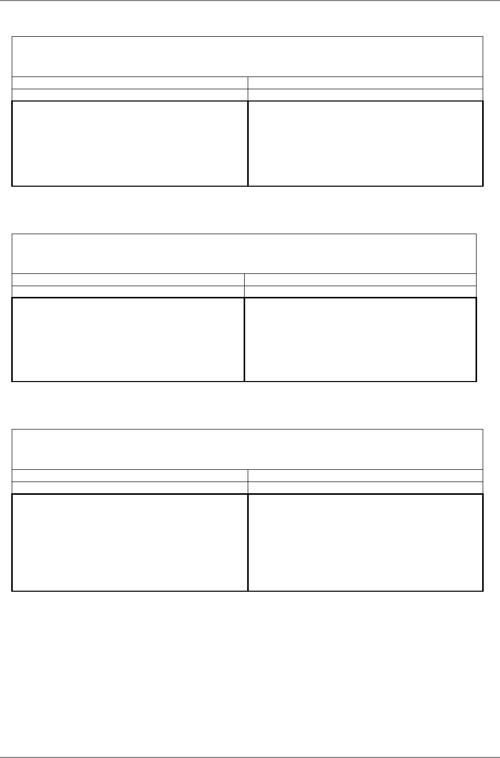
TX channel nominal frequencies
Band 10.7 – 11.7 GHz, duplex spacing 530 MHz
Bandwidth: 40 MHz (ITU) ITU-R F.387 rec.1.1,
( Freq. table: rcinfo11_A_530:13 ) ( Freq. table: rcinfo11_B_530:13 )
Ch.No. Lower [MHz] Upper [MHz] Ch.No. Lower [MHz] Upper [MHz]
6
1 10715 11245 7 10955 11485
2 10755 11285 8 10995 11525
3 10795 11325 9 11035 11565
4 10835 11365 10 11075 11605
5 10875 11405 11 11115 11645
ver. 1.1
RAy2-11 - xA, RAy2-11 - xB
A sub-band B sub-band
TX channel nominal frequencies
Band 10.7 – 11.7 GHz, duplex spacing 530 MHz
Bandwidth: 40 MHz (CEPT) CEPT 12-06 Annex A.1
( Freq. table: rcinfo11_A_530:13 ) ( Freq. table: rcinfo11_B_530:13 )
Ch.No. Lower [MHz] Upper [MHz] Ch.No. Lower [MHz] Upper [MHz]
6
1 10735 11265 7 10975 11505
2 10775 11305 8 11015 11545
3 10815 11345 9 11055 11585
4 10855 11385 10 11095 11625
5 10895 11425 11 11135 11665
ver. 1.2
RAy2-11 - xA, RAy2-11 - xB
A sub-band B sub-band
TX channel nominal frequencies
Band 10.7 – 11.7 GHz, duplex spacing 530 MHz
Bandwidth: 56 MHz CEPT 12-06, Annex C
( Freq. table: rcinfo11_A_530:13 ) ( Freq. table: rcinfo11_B_530:13 )
Ch.No. Lower [MHz] Upper [MHz] Ch.No. Lower [MHz] Upper [MHz]
9
1 10737 11267 10 10989 11519
2 10765 11295 11 11017 11547
3 10793 11323 12 11045 11575
4 10821 11351 13 11073 11603
5 10849 11379 14 11101 11631
6 10877 11407 15 11129 11659
ver. 2.2
RAy2-11 - xA, RAy2-11 - xB
A sub-band B sub-band
RAy2 Microwave Link – © RACOM s.r.o.202
Technical parameters

TX channel nominal frequencies
Band 10.7 – 11.7 GHz, duplex spacing 530 MHz
Bandwidth: 56 (CS 80) MHz CEPT 12-06, Annex C
( Freq. table: rcinfo11_A_530:13 ) ( Freq. table: rcinfo11_B_530:13 )
Ch.No. Lower [MHz] Upper [MHz] Ch.No. Lower [MHz] Upper [MHz]
6
1 10755 11285 7 10995 11525
2 10795 11325 8 11035 11565
3 10835 11365 9 11075 11605
4 10875 11405 10 11115 11645
ver. 1.1
RAy2-11 - xA, RAy2-11 - xB
A sub-band B sub-band
203© RACOM s.r.o. – RAy2 Microwave Link
Technical parameters

10.5. RAy2-11 C,D parameters
Note
The RAy2-11-C,D units are not available yet
RAy2 Microwave Link – © RACOM s.r.o.204
Technical parameters
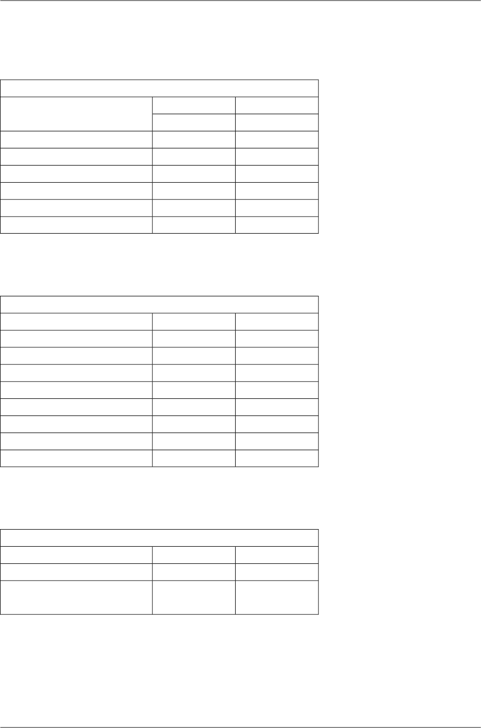
10.6. RAy2-17 parameters
10.6.1. Upper/Lower Limits
TX powerRAy2-17
MaxMin
Modulation [dBm][dBm]
5-25QPSK
5-2516-QAM
5-2532-QAM
5-2564-QAM
5-25128-QAM
5-25256-QAM
ver. 2.0
Minimum (hw limit) and default duplex spacing.
Optional duplex spacingRAy2-17
defaultminChannel width
[MHz][MHz][MHz]
73.5603.5
73.5607
87.56514
847028
707040
87.58450
848456
ver. 2.6
Band RangeRAy2-17
Unit UUnit L
[MHz][MHz]
17.10017.100min
17.30017.300max
ver. 1.0
205© RACOM s.r.o. – RAy2 Microwave Link
Technical parameters

10.6.2. Radio parameters
Channel spacing 3.5 MHz; ACCP operationRAy2-17
Adjacent channel SelectivityCo-channel rejection
RSS / SNR for
BER 10-6
User
Bit
Rate
Raw
Bit
Rate
Modula-
tion
3 dB1 dB3 dB1 dB
declared / limitdeclared / limitdeclared / limitdeclared / limitSNRRSS
[dB][dB][dB][dB][dB][dBm][Mbps][-]
-4/-160/-1419/1223/159.5-974.96QPSK
-7/-15-3/-1326.5/2030/2215.0-909.61216-QAM
-7/-14-3/-1226.5/2230/2418.5-8712.11532-QAM
-7/-12-3/-1126.5/2630/2920.5-8414.31864-QAM
-7/-8-3/-926.5/2830/3023.5-8317.221128-QAM
-7/-7-3/-526.5/3130/3326.0-8119.724256-QAM
ver. 2.1
Channel spacing 7 MHz; ACCP operationRAy2-17
Adjacent channel SelectivityCo-channel rejection
RSS / SNR for
BER 10-6
User
Bit
Rate
Raw
Bit
Rate
Modula-
tion
3 dB1 dB3 dB1 dB
declared / limitdeclared / limitdeclared / limitdeclared / limitSNRRSS
[dB][dB][dB][dB][dB][dBm][Mbps][-]
-4/-220/-2019/1223/158.5-958.512QPSK
-7/-19-3/-1826.5/2030/2215.0-8817.22416-QAM
-6/-18-2/-1633/2237/2418.5-8522.13032-QAM
-6/-16-2/-1433/2637/2921.5-8129.73664-QAM
-6/-14-2/-1233/3037/3225.0-7934.742128-QAM
-6/-12-2/-1033/3137/3326.0-7739.749256-QAM
ver. 2.1
RAy2 Microwave Link – © RACOM s.r.o.206
Technical parameters

Channel spacing 14 MHz; ACCP operationRAy2-17
Adjacent channel SelectivityCo-channel rejection
RSS / SNR for
BER 10-6
User
Bit
Rate
Raw
Bit
Rate
Modula-
tion
3 dB1 dB3 dB1 dB
declared / limitdeclared / limitdeclared / limitdeclared / limitSNRRSS
[dB][dB][dB][dB][dB][dBm][Mbps][-]
-4/-230/-2119/1223/148.5-9219.924QPSK
-7/-21-3/-1926.5/1830/2015.0-8538.84816-QAM
-9/-19-5/-1729/2333/2618.5-8149.16032-QAM
-6/-17-2/-1433/2637/2821.5-7862.37264-QAM
-6/-14-2/-1233/2837/3025.0-7573.684128-QAM
-6/-12-2/-1033/3137/3328.0-7381.296256-QAM
ver. 2.1
Channel spacing 28 MHz; ACCP operationRAy2-17
Adjacent channel SelectivityCo-channel rejection
RSS / SNR for
BER 10-6
User
Bit
Rate
Raw
Bit
Rate
Modula-
tion
3 dB1 dB3 dB1 dB
declared / limitdeclared / limitdeclared / limitdeclared / limitSNRRSS
[dB][dB][dB][dB][dB][dBm][Mbps][-]
-4/-230/-2119/1023/127.5-9036.850QPSK
-7/-20-3/-1826.5/1830/2015.0-8380.910016-QAM
-9/-19-5/-1629/2233/2418.5-79102.412532-QAM
-8/-15-5/-1232/2635/2821.5-76129.815064-QAM
-8/-12-5/-932/2835/3025.0-72155.5175128QAM
-8/-9-5/-632/3135/3326.5-69170.7200256-QAM
ver. 2.0
Channel spacing 40 MHz; ACCP operationRAy2-17
Adjacent channel SelectivityCo-channel rejection
RSS / SNR for
BER 10-6
User
Bit
Rate
Raw
Bit
Rate
Modula-
tion
3 dB1 dB3 dB1 dB
declared / limitdeclared / limitdeclared / limitdeclared / limitSNRRSS
[dB][dB][dB][dB][dB][dBm][Mbps][-]
-8/-24-4/-2229/1033/127.5-8850.168QPSK
-8/-21-4/-1829/1733/1915.0-81110.013616-QAM
-8/-19-4/-1629/2133/2418.5-77139.217032-QAM
-8/-16-4/-1429/2533/2721.5-74176.520464-QAM
-8/-12-4/-1033/2837/3025.0-70211.4238128QAM
-8/-10-4/-833/3037/3326.5-68232.1272256-QAM
ver. 2.0
207© RACOM s.r.o. – RAy2 Microwave Link
Technical parameters

Channel spacing 50 MHz; ACCP operationRAy2-17
Adjacent channel SelectivityCo-channel rejection
RSS / SNR for
BER 10-6
User
Bit
Rate
Raw
Bit
Rate
Modula-
tion
3 dB1 dB3 dB1 dB
declared / limitdeclared / limitdeclared / limitdeclared / limitSNRRSS
[dB][dB][dB][dB][dB][dBm][Mbps][-]
-4/-260/-2419/1023/127.5-87.566.390QPSK
-7/-21-3/-1826.5/1730/1915.0-80.5145.618016-QAM
-9/-19-5/-1629/2233/2418.5-76.5184.222532-QAM
-8/-16-5/-1432/2535/2721.5-73.5233.627064-QAM
-8/-12-5/-1032/2835/3025.0-69.5276.1315128QAM
-8/-10-5/-832/3035/3326.5-66.5320.6360256-QAM
ver. 1.0
Channel spacing 56 MHz; ACCP operationRAy2-17
Adjacent channel SelectivityCo-channel rejection
RSS / SNR for
BER 10-6
User
Bit
Rate
Raw
Bit
Rate
Modula-
tion
3 dB1 dB3 dB1 dB
declared / limitdeclared / limitdeclared / limitdeclared / limitSNRRSS
[dB][dB][dB][dB][dB][dBm][Mbps][-]
-4/-260/-2419/1023/127.5-8772.999QPSK
-7/-21-3/-1826.5/1730/1915.0-80160.219816-QAM
-9/-19-5/-1629/2233/2418.5-76202.7247.532-QAM
-8/-16-5/-1432/2535/2721.5-73256.929764-QAM
-8/-12-5/-1032/2835/3025.0-69303.7346.5128QAM
-8/-10-5/-832/3035/3326.5-66337.7396256-QAM
ver. 2.0
Channel spacing 56 MHz TO; ACCP operationRAy2-17
Adjacent channel SelectivityCo-channel rejection
RSS / SNR for
BER 10-6
User
Bit
Rate
Raw
Bit
Rate
Modula-
tion
3 dB1 dB3 dB1 dB
declared / limitdeclared / limitdeclared / limitdeclared / limitSNRRSS
[dB][dB][dB][dB][dB][dBm][Mbps][-]
-4/-260/-2419/1123/1310.0-8585.899QPSK
-7/-20-3/-1826.5/1830/2016.0-78169.919816-QAM
-9/-15-5/-1429/2333/2519.0-74206.2247.532-QAM
-8/-11-5/-932/2635/2922.5-70268.129764-QAM
-8/-10-5/-832/2935/3225.5-67309.0346.5128-QAM
-8/-8-5/-732/3235/3527.5-64358.9396256-QAM
ver. 2.1
RAy2 Microwave Link – © RACOM s.r.o.208
Technical parameters

10.6.3. Nominal frequencies
RAy2-17 TX channel nominal frequencies
duplex spacing range 63 – 189 MHz
(Freq.table: rcinfo17_default:14)
basic channels (default duplex) optional channels
Ch.No. Lower [MHz] Ch.No. Upper [MHz] Ch.No. Lower [MHz] Ch.No. Upper [MHz]
###
U19 17168.0
###
no more channels
U20 17171.5
###
U21 17175.0
###
L1 17105.0 U22 17178.5
###
L2 17108.5 U23 17182.0
###
L3 17112.0 U24 17185.5
###
L4 17115.5 U25 17189.0
###
L5 17119.0 U26 17192.5
###
L6 17122.5 U27 17196.0
###
L7 17126.0 U28 17199.5
###
L8 17129.5 U29 17203.0
###
L9 17133.0 U30 17206.5
###
L10 17136.5 U31 17210.0
###
L11 17140.0 U32 17213.5
###
L12 17143.5 U33 17217.0
###
L13 17147.0 U34 17220.5
###
L14 17150.5 U35 17224.0
###
L15 17154.0 U36 17227.5
###
L16 17157.5 U37 17231.0
###
L17 17161.0 U38 17234.5
###
L18 17164.5 U39 17238.0
###
L19 17168.0 U40 17241.5
###
L20 17171.5 U41 17245.0
###
L21 17175.0 U42 17248.5
###
L22 17178.5 U43 17252.0
###
L23 17182.0 U44 17255.5
###
L24 17185.5 U45 17259.0
###
L25 17189.0 U46 17262.5
###
L26 17192.5 U47 17266.0
###
L27 17196.0 U48 17269.5
###
L28 17199.5 U49 17273.0
###
L29 17203.0 U50 17276.5
###
L30 17206.5 U51 17280.0
###
L31 17210.0 U52 17283.5
###
L32 17213.5 U53 17287.0
###
L33 17217.0 U54 17290.5
###
L34 17220.5 U55 17294.0
###
L35 17224.0
###
L36 17227.5
###
L37 17231.0
ver. 2.1
Band 17.1 – 17.3 GHz, default duplex sp. 73.5 MHz
Bandwidth: 3.5 MHz
209© RACOM s.r.o. – RAy2 Microwave Link
Technical parameters

RAy2-17 TX channel nominal frequencies
duplex spacing range 63 – 189 MHz
(Freq.table: rcinfo17_default:14)
basic channels (default duplex) optional channels
Ch.No. Lower [MHz] Ch.No. Upper [MHz] Ch.No. Lower [MHz] Ch.No. Upper [MHz]
U19 17168.0
U20 17171.5
U21 17175.0
L1 17105.0 U22 17178.5
L2 17108.5 U23 17182.0
L3 17112.0 U24 17185.5
L4 17115.5 U25 17189.0
L5 17119.0 U26 17192.5
L6 17122.5 U27 17196.0
L7 17126.0 U28 17199.5
L8 17129.5 U29 17203.0
L9 17133.0 U30 17206.5
L10 17136.5 U31 17210.0
L11 17140.0 U32 17213.5
L12 17143.5 U33 17217.0
L13 17147.0 U34 17220.5
L14 17150.5 U35 17224.0
L15 17154.0 U36 17227.5
L16 17157.5 U37 17231.0
L17 17161.0 U38 17234.5
L18 17164.5 U39 17238.0
L19 17168.0 U40 17241.5
L20 17171.5 U41 17245.0
L21 17175.0 U42 17248.5
L22 17178.5 U43 17252.0
L23 17182.0 U44 17255.5
L24 17185.5 U45 17259.0
L25 17189.0 U46 17262.5
L26 17192.5 U47 17266.0
L27 17196.0 U48 17269.5
L28 17199.5 U49 17273.0
L29 17203.0 U50 17276.5
L30 17206.5 U51 17280.0
L31 17210.0 U52 17283.5
L32 17213.5 U53 17287.0
L33 17217.0 U54 17290.5
L34 17220.5 U55 17294.0
L35 17224.0
L36 17227.5
L37 17231.0
ver. 2.1
Band 17.1 – 17.3 GHz, default duplex sp. 73.5 MHz
Bandwidth: 7 MHz
RAy2 Microwave Link – © RACOM s.r.o.210
Technical parameters

RAy2-17 TX channel nominal frequencies
duplex spacing range 66.5 – 182 MHz
(Freq.table: rcinfo17_default:14)
basic channels (default duplex) optional channels
Ch.No. Lower [MHz] Ch.No. Upper [MHz] Ch.No. Lower [MHz] Ch.No. Upper [MHz]
###
###
###
###
U21 17175.0
###
U22 17178.5
###
###
###
U23 17182.0
###
###
U24 17185.5
###
###
U25 17189.0
U26 17192.5
###
###
L2 17108.5 U27 17196.0
###
L3 17112.0 U28 17199.5
###
L4 17115.5 U29 17203.0
L5 17119.0 U30 17206.5
###
###
L6 17122.5 U31 17210.0
###
L7 17126.0 U32 17213.5
###
L8 17129.5 U33 17217.0
L9 17133.0 U34 17220.5
###
###
L10 17136.5 U35 17224.0
###
L11 17140.0 U36 17227.5
###
L12 17143.5 U37 17231.0
L13 17147.0 U38 17234.5
###
###
L14 17150.5 U39 17238.0
###
L15 17154.0 U40 17241.5
###
L16 17157.5 U41 17245.0
L17 17161.0 U42 17248.5
###
###
L18 17164.5 U43 17252.0
###
L19 17168.0 U44 17255.5
###
L20 17171.5 U45 17259.0
L21 17175.0 U46 17262.5
###
###
L22 17178.5 U47 17266.0
###
L23 17182.0 U48 17269.5
###
L24 17185.5 U49 17273.0
L25 17189.0 U50 17276.5
###
###
L26 17192.5 U51 17280.0
###
L27 17196.0 U52 17283.5
###
L28 17199.5 U53 17287.0
L29 17203.0 U54 17290.5
###
###
L30 17206.5
###
L31 17210.0
###
L32 17213.5
L33 17217.0
###
###
L34 17220.5
###
L35 17224.0
###
ver. 2.1
Band 17.1 – 17.3 GHz, default duplex sp. 87.5 MHz
Bandwidth: 14 MHz
211© RACOM s.r.o. – RAy2 Microwave Link
Technical parameters

RAy2-17 TX channel nominal frequencies
duplex spacing range 70 – 168 MHz
(Freq.table: rcinfo17_default:14)
basic channels (default duplex) optional channels
Ch.No. Lower [MHz] Ch.No. Upper [MHz] Ch.No. Lower [MHz] Ch.No. Upper [MHz]
U24 17185.5
U25 17189.0
U26 17192.5
U27 17196.0
L4 17115.5 U28 17199.5
L5 17119.0 U29 17203.0
L6 17122.5 U30 17206.5
L7 17126.0 U31 17210.0
L8 17129.5 U32 17213.5
L9 17133.0 U33 17217.0
L10 17136.5 U34 17220.5
L11 17140.0 U35 17224.0
L12 17143.5 U36 17227.5
L13 17147.0 U37 17231.0
L14 17150.5 U38 17234.5
L15 17154.0 U39 17238.0
L16 17157.5 U40 17241.5
L17 17161.0 U41 17245.0
L18 17164.5 U42 17248.5
L19 17168.0 U43 17252.0
L20 17171.5 U44 17255.5
L21 17175.0 U45 17259.0
L22 17178.5 U46 17262.5
L23 17182.0 U47 17266.0
L24 17185.5 U48 17269.5
L25 17189.0 U49 17273.0
L26 17192.5 U50 17276.5
L27 17196.0 U51 17280.0
L28 17199.5 U52 17283.5
L29 17203.0
L30 17206.5
L31 17210.0
L32 17213.5
ver. 2.1
Band 17.1 – 17.3 GHz, default duplex sp. 84 MHz
Bandwidth: 28 MHz
RAy2 Microwave Link – © RACOM s.r.o.212
Technical parameters

RAy2-17 TX channel nominal frequencies
duplex spacing range 70 – 154 MHz
(Freq.table: rcinfo17_default:14)
basic channels (default duplex) optional channels
Ch.No. Lower [MHz] Ch.No. Upper [MHz] Ch.No. Lower [MHz] Ch.No. Upper [MHz]
L6 17122.5 U26 17192.5
L7 17126.0 U27 17196.0
L8 17129.5 U28 17199.5
L9 17133.0 U29 17203.0
L10 17136.5 U30 17206.5
L11 17140.0 U31 17210.0
L12 17143.5 U32 17213.5
L13 17147.0 U33 17217.0
L14 17150.5 U34 17220.5
L15 17154.0 U35 17224.0
L16 17157.5 U36 17227.5
L17 17161.0 U37 17231.0
L18 17164.5 U38 17234.5
L19 17168.0 U39 17238.0
L20 17171.5 U40 17241.5
L21 17175.0 U41 17245.0
L22 17178.5 U42 17248.5
L23 17182.0 U43 17252.0
L24 17185.5 U44 17255.5
L25 17189.0 U45 17259.0
L26 17192.5 U46 17262.5
L27 17196.0 U47 17266.0
L28 17199.5 U48 17269.5
L29 17203.0 U49 17273.0
L30 17206.5 U50 17276.5
ver. 2.1
Band 17.1 – 17.3 GHz, default duplex sp. 70 MHz
Bandwidth: 40 MHz
213© RACOM s.r.o. – RAy2 Microwave Link
Technical parameters

RAy2-17 TX channel nominal frequencies
Band 17.1 – 17.3 GHz, duplex spacing 87.5 MHz
Bandwidth: 50 MHz duplex spacing range 84 – 143.5 MHz
(Freq.table: rcinfo17_default:17)
basic channels (default duplex) optional channels
Ch.No. Lower [MHz] Ch.No. Upper [MHz] Ch.No. Lower [MHz] Ch.No. Upper [MHz]
U32 17213.5
L8 17129.5 U33 17217.0
L9 17133.0 U34 17220.5
L10 17136.5 U35 17224.0
L11 17140.0 U36 17227.5
L12 17143.5 U37 17231.0
L13 17147.0 U38 17234.5
L14 17150.5 U39 17238.0
L15 17154.0 U40 17241.5
L16 17157.5 U41 17245.0
L17 17161.0 U42 17248.5
L18 17164.5 U43 17252.0
L19 17168.0 U44 17255.5
L20 17171.5 U45 17259.0
L21 17175.0 U46 17262.5
L22 17178.5 U47 17266.0
L23 17182.0 U48 17269.5
L24 17185.5 U49 17273.0
L25 17189.0
ver. 1.0
RAy2 Microwave Link – © RACOM s.r.o.214
Technical parameters

RAy2-17 TX channel nominal frequencies
duplex spacing range 84 – 140 MHz
(Freq.table: rcinfo17_default:14)
basic channels (default duplex) optional channels
Ch.No. Lower [MHz] Ch.No. Upper [MHz] Ch.No. Lower [MHz] Ch.No. Upper [MHz]
###
###
L8 17129.5 U32 17213.5
L9 17133.0 U33 17217.0
L10 17136.5 U34 17220.5
L11 17140.0 U35 17224.0
L12 17143.5 U36 17227.5
L13 17147.0 U37 17231.0
L14 17150.5 U38 17234.5
L15 17154.0 U39 17238.0
L16 17157.5 U40 17241.5
L17 17161.0 U41 17245.0
L18 17164.5 U42 17248.5
L19 17168.0 U43 17252.0
L20 17171.5 U44 17255.5
L21 17175.0 U45 17259.0
L22 17178.5 U46 17262.5
L23 17182.0 U47 17266.0
L24 17185.5 U48 17269.5
ver. 2.1
Band 17.1 – 17.3 GHz, default duplex sp. 84 MHz
Bandwidth: 56 MHz
215© RACOM s.r.o. – RAy2 Microwave Link
Technical parameters
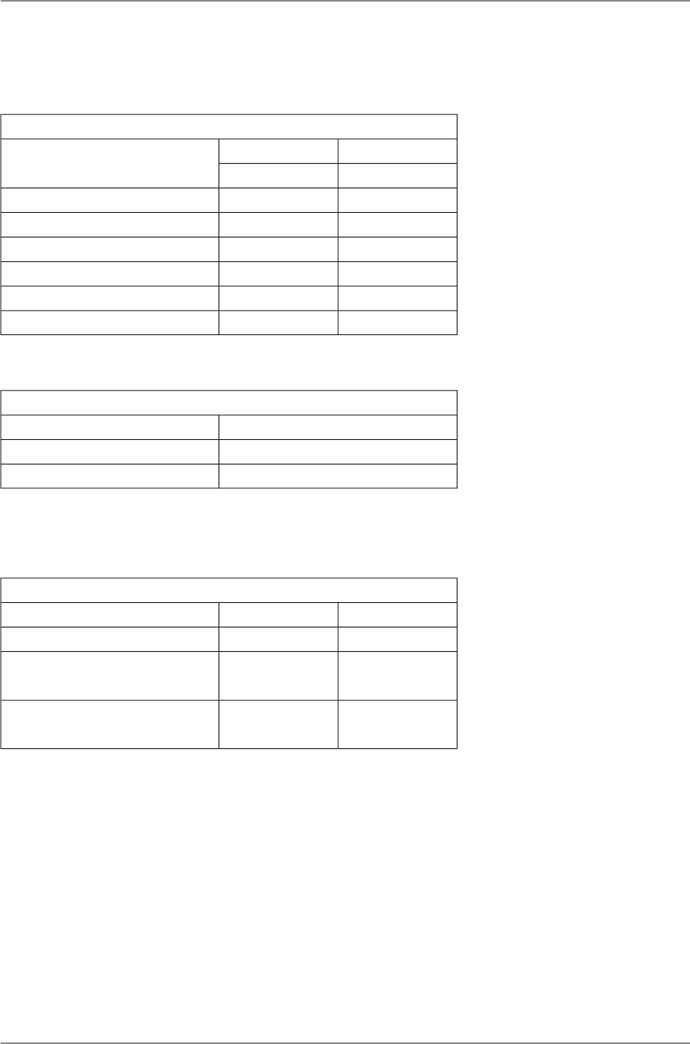
10.7. RAy2-18 parameters
10.7.1. Upper/Lower Limits
TX powerRAy2-18-xA,RAy2-18-xB
MaxMin
Modulation [dBm][dBm]
24-10QPSK
23-1016-QAM
22-1032-QAM
21-1064-QAM
20-10128-QAM
19-10256-QAM
ver. 1.0
Duplex spacingRAy2-18-xA,RAy2-18-xB
[MHz]Sub-band
1008, 1010A
1008, 1010B
ver. 1.0
Sub-band RangeRAy2-18-xA,RAy2-18-xB
Unit UUnit LSub-band
[MHz][MHz]
18.71017.700min
A19.21918.209max
19.17718.167min
B19.70018.690max
ver. 1.0
RAy2 Microwave Link – © RACOM s.r.o.216
Technical parameters
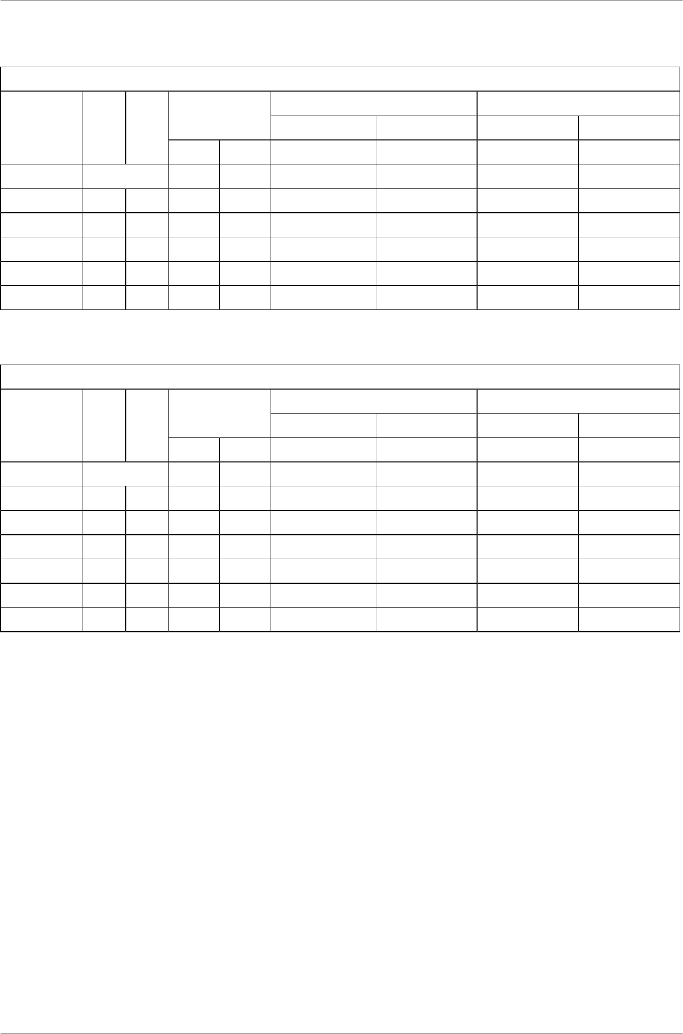
10.7.2. Radio parameters
Channel spacing 1.75 MHz; ACCP operationRAy2-18
Adjacent channel SelectivityCo-channel rejection
RSS / SNR for
BER 10-6
User
Bit
Rate
Raw
Bit
Rate
Modula-
tion
3 dB1 dB3 dB1 dB
declared / limitdeclared / limitdeclared / limitdeclared / limitSNRRSS
[dB][dB][dB][dB][dB][dBm][Mbps][-]
-4/-140/-1219/1223/159.5-972.543.13QPSK
-5/-13-1/-1126.5/2030/2215.0-914.956.2616-QAM
-5/-12-1/-1026.5/2230/2419.0-886.267.8332-QAM
-5/-10-1/-926.5/2630/2920.5-857.379.3964-QAM
-5/-7-1/-826.5/2830/3023.5-82.58.8910.96128-QAM
ver. 1.0
Channel spacing 2.5 MHz; ACCP operationRAy2-18
Adjacent channel SelectivityCo-channel rejection
RSS / SNR for
BER 10-6
User
Bit
Rate
Raw
Bit
Rate
Modula-
tion
3 dB1 dB3 dB1 dB
declared / limitdeclared / limitdeclared / limitdeclared / limitSNRRSS
[dB][dB][dB][dB][dB][dBm][Mbps][-]
-4/-160/-1419/1223/158.5-96.03.244QPSK
-5/-15-1/-1326.5/2030/2215.0-90.56.33816-QAM
-8/-14-4/-1226.5/2230/2418.5-87.58.011032-QAM
-8/-12-4/-1126.5/2630/2921.5-84.59.421264-QAM
-4/-80/-933/2837/3025.0-81.511.3614128-QAM
-4/-70/-533/3137/3326.0-78.513.0116256-QAM
ver 1.0
217© RACOM s.r.o. – RAy2 Microwave Link
Technical parameters

Channel spacing 3.5 MHz; ACCP operationRAy2-18
Adjacent channel SelectivityCo-channel rejection
RSS / SNR for
BER 10-6
User
Bit
Rate
Raw
Bit
Rate
Modula-
tion
3 dB1 dB3 dB1 dB
declared / limitdeclared / limitdeclared / limitdeclared / limitSNRRSS
[dB][dB][dB][dB][dB][dBm][Mbps][-]
-4/-160/-1419/1223/159.5-944.96QPSK
-5/-15-1/-1326.5/2030/2215.0-899.61216-QAM
-8/-14-4/-1226.5/2230/2418.5-8612.11532-QAM
-8/-12-4/-1126.5/2630/2920.5-8314.31864-QAM
-4/-80/-933/2837/3023.5-8017.221128-QAM
-4/-70/-533/3137/3326.0-7719.724256-QAM
ver. 1.0
Channel spacing 3.75 MHz; ACCP operationRAy2-18
Adjacent channel SelectivityCo-channel rejection
RSS / SNR for
BER 10-6
User
Bit
Rate
Raw
Bit
Rate
Modula-
tion
3 dB1 dB3 dB1 dB
declared / limitdeclared / limitdeclared / limitdeclared / limitSNRRSS
[dB][dB][dB][dB][dB][dBm][Mbps][-]
-4/-160/-1419/1223/159.5-944.96QPSK
-5/-15-1/-1326.5/2030/2215.0-899.61216-QAM
-8/-14-4/-1226.5/2230/2418.5-8612.11532-QAM
-8/-12-4/-1126.5/2630/2920.5-8314.31864-QAM
-4/-80/-933/2837/3023.5-8017.221128-QAM
-4/-70/-533/3137/3326.0-7719.724256-QAM
ver. 1.0
Channel spacing 5 MHz; ACCP operationRAy2-18
Adjacent channel SelectivityCo-channel rejection
RSS / SNR for
BER 10-6
User
Bit
Rate
Raw
Bit
Rate
Modula-
tion
3 dB1 dB3 dB1 dB
declared / limitdeclared / limitdeclared / limitdeclared / limitSNRRSS
[dB][dB][dB][dB][dB][dBm][Mbps][-]
-4/-160/-1419/1223/158.5-94.55.78QPSK
-5/-15-1/-1326.5/2030/2215.0-87.511.51616-QAM
-8/-14-4/-1226.5/2230/2418.5-84.514.82032-QAM
-8/-12-4/-1126.5/2630/2921.5-81.519.82464-QAM
-4/-80/-933/2837/3025.0-78.523.128128-QAM
-4/-70/-533/3137/3326.0-75.527.232256-QAM
ver 1.0
RAy2 Microwave Link – © RACOM s.r.o.218
Technical parameters

Channel spacing 7 MHz; ACCP operationRAy2-18
Adjacent channel SelectivityCo-channel rejection
RSS / SNR for
BER 10-6
User
Bit
Rate
Raw
Bit
Rate
Modula-
tion
3 dB1 dB3 dB1 dB
declared / limitdeclared / limitdeclared / limitdeclared / limitSNRRSS
[dB][dB][dB][dB][dB][dBm][Mbps][-]
-4/-220/-2019/1223/158.5-928.512QPSK
-5/-19-1/-1826.5/2030/2215.0-8517.22416-QAM
-5/-18-1/-1626.5/2230/2418.5-8222.13032-QAM
-7/-16-3/-1430/2634/2921.5-7929.73664-QAM
-7.5/-14-3.5/-1233/3037/3225.0-7634.742128-QAM
-4/-120/-1036/3140/3326.0-7339.749256-QAM
ver. 1.0
Channel spacing 7.5 MHz; ACCP operationRAy2-18
Adjacent channel SelectivityCo-channel rejection
RSS / SNR for
BER 10-6
User
Bit
Rate
Raw
Bit
Rate
Modula-
tion
3 dB1 dB3 dB1 dB
declared / limitdeclared / limitdeclared / limitdeclared / limitSNRRSS
[dB][dB][dB][dB][dB][dBm][Mbps][-]
-4/-220/-2019/1223/158.5-92.59.112.9QPSK
-7/-19-3/-1826.5/2030/2215.0-84.518.425.716-QAM
-7/-18-3/-1626.5/2230/2418.5-81.523.732.232-QAM
-7/-16-3/-1430/2634/2921.5-78.531.838.664-QAM
-6/-14-2/-1233/3037/3225.0-75.537.145.0128-QAM
-4/-120/-1036/3140/3326.0-72.542.551.4256-QAM
ver. 1.0
Channel spacing 13.75 MHz; ACCP operationRAy2-18
Adjacent channel SelectivityCo-channel rejection
RSS / SNR for
BER 10-6
User
Bit
Rate
Raw
Bit
Rate
Modula-
tion
3 dB1 dB3 dB1 dB
declared / limitdeclared / limitdeclared / limitdeclared / limitSNRRSS
[dB][dB][dB][dB][dB][dBm][Mbps][-]
-3/-231/-2119/1223/148.5-8919.924QPSK
-4/-210/-1926.5/1830/2015.0-8338.84816-QAM
-5.5/-19-2/-1726.5/2330/2618.5-8049.16032-QAM
-7/-17-3/-1430/2634/2821.5-7762.37264-QAM
-7.5/-14-3.5/-1233/2837/3025.0-7473.684128-QAM
-4/-120/-1036/3140/3328.0-7181.296256-QAM
ver. 1.0
219© RACOM s.r.o. – RAy2 Microwave Link
Technical parameters

Channel spacing 27.5 MHz; ACCP operationRAy2-18
Adjacent channel SelectivityCo-channel rejection
RSS / SNR for
BER 10-6
User
Bit
Rate
Raw
Bit
Rate
Modula-
tion
3 dB1 dB3 dB1 dB
declared / limitdeclared / limitdeclared / limitdeclared / limitSNRRSS
[dB][dB][dB][dB][dB][dBm][Mbps][-]
-3/-231/-2119/1023/127.5-8736.850QPSK
-4/-200/-1826.5/1830/2015.0-7980.910016-QAM
-5.5/-19-2/-1626.5/2230/2418.5-76102.412532-QAM
-7/-15-3/-1230/2634/2821.5-73129.815064-QAM
-7/-12-3/-933/2837/3025.0-70155.5175128-QAM
-4/-90/-636/3140/3326.5-67170.7200256-QAM
ver. 1.0
Channel spacing 55 MHz; ACCP operationRAy2-18
Adjacent channel SelectivityCo-channel rejection
RSS / SNR for
BER 10-6
User
Bit
Rate
Raw
Bit
Rate
Modula-
tion
3 dB1 dB3 dB1 dB
declared / limitdeclared / limitdeclared / limitdeclared / limitSNRRSS
[dB][dB][dB][dB][dB][dBm][Mbps][-]
-3/-261/-2419/1023/127.5-8472.999QPSK
-9/-21-5/-1825/1729/1915.0-75160.219816-QAM
-5.5/-19-2/-1626.5/2230/2418.5-72.5202.7247.532-QAM
-7/-16-3/-1430/2534/2721.5-70256.929764-QAM
-7.5/-12-3.5/-1033/2837/3025.0-67303.7346.5128-QAM
-4/-100/-836/3040/3326.5-64337.7396256-QAM
ver. 1.0
Channel spacing 55 MHz TO; ACCP operationRAy2-18
Adjacent channel SelectivityCo-channel rejection
RSS / SNR for
BER 10-6
User
Bit
Rate
Raw
Bit
Rate
Modula-
tion
3 dB1 dB3 dB1 dB
declared / limitdeclared / limitdeclared / limitdeclared / limitSNRRSS
[dB][dB][dB][dB][dB][dBm][Mbps][-]
-3/-261/-2419/1123/1310.0-8485.899QPSK
-9/-20-5/-1825/1829/2016.0-77169.919816-QAM
-5.5/-15-2/-1426.5/2330/2519.0-73206.2247.532-QAM
-7/-11-3/-930/2634/2922.5-69268.129764-QAM
-7.5/-10-3.5/-833/2937/3225.5-66309.0346.5128-QAM
-4/-80/-736/3240/3527.5-63358.9396256-QAM
ver. 1.0
RAy2 Microwave Link – © RACOM s.r.o.220
Technical parameters

10.7.3. Nominal frequencies
TX channel nominal frequencies
Band 17.7 – 19.7 GHz, duplex spacing 1010 MHz
Bandwidth: 1.75 MHz ITU-R F.595-9 (-10), Annex 5.c
( Freq.table: rcinfo18_A_default:5 )
Ch.No. Lower [MHz] Upper [MHz] Ch.No. Lower [MHz] Upper [MHz] Ch.No. Lower [MHz] Upper [MHz] Ch.No. Lower [MHz] Upper [MHz]
1 17703.875 18713.875 74 17831.625 18841.625 147 17959.375 18969.375 220 18087.125 19097.125
2 17705.625 18715.625 75 17833.375 18843.375 148 17961.125 18971.125 221 18088.875 19098.875
3 17707.375 18717.375 76 17835.125 18845.125 149 17962.875 18972.875 222 18090.625 19100.625
4 17709.125 18719.125 77 17836.875 18846.875 150 17964.625 18974.625 223 18092.375 19102.375
5 17710.875 18720.875 78 17838.625 18848.625 151 17966.375 18976.375 224 18094.125 19104.125
6 17712.625 18722.625 79 17840.375 18850.375 152 17968.125 18978.125 225 18095.875 19105.875
7 17714.375 18724.375 80 17842.125 18852.125 153 17969.875 18979.875 226 18097.625 19107.625
8 17716.125 18726.125 81 17843.875 18853.875 154 17971.625 18981.625 227 18099.375 19109.375
9 17717.875 18727.875 82 17845.625 18855.625 155 17973.375 18983.375 228 18101.125 19111.125
10 17719.625 18729.625 83 17847.375 18857.375 156 17975.125 18985.125 229 18102.875 19112.875
11 17721.375 18731.375 84 17849.125 18859.125 157 17976.875 18986.875 230 18104.625 19114.625
12 17723.125 18733.125 85 17850.875 18860.875 158 17978.625 18988.625 231 18106.375 19116.375
13 17724.875 18734.875 86 17852.625 18862.625 159 17980.375 18990.375 232 18108.125 19118.125
14 17726.625 18736.625 87 17854.375 18864.375 160 17982.125 18992.125 233 18109.875 19119.875
15 17728.375 18738.375 88 17856.125 18866.125 161 17983.875 18993.875 234 18111.625 19121.625
16 17730.125 18740.125 89 17857.875 18867.875 162 17985.625 18995.625 235 18113.375 19123.375
17 17731.875 18741.875 90 17859.625 18869.625 163 17987.375 18997.375 236 18115.125 19125.125
18 17733.625 18743.625 91 17861.375 18871.375 164 17989.125 18999.125 237 18116.875 19126.875
19 17735.375 18745.375 92 17863.125 18873.125 165 17990.875 19000.875 238 18118.625 19128.625
20 17737.125 18747.125 93 17864.875 18874.875 166 17992.625 19002.625 239 18120.375 19130.375
21 17738.875 18748.875 94 17866.625 18876.625 167 17994.375 19004.375 240 18122.125 19132.125
22 17740.625 18750.625 95 17868.375 18878.375 168 17996.125 19006.125 241 18123.875 19133.875
23 17742.375 18752.375 96 17870.125 18880.125 169 17997.875 19007.875 242 18125.625 19135.625
24 17744.125 18754.125 97 17871.875 18881.875 170 17999.625 19009.625 243 18127.375 19137.375
25 17745.875 18755.875 98 17873.625 18883.625 171 18001.375 19011.375 244 18129.125 19139.125
26 17747.625 18757.625 99 17875.375 18885.375 172 18003.125 19013.125 245 18130.875 19140.875
27 17749.375 18759.375 100 17877.125 18887.125 173 18004.875 19014.875 246 18132.625 19142.625
28 17751.125 18761.125 101 17878.875 18888.875 174 18006.625 19016.625 247 18134.375 19144.375
29 17752.875 18762.875 102 17880.625 18890.625 175 18008.375 19018.375 248 18136.125 19146.125
30 17754.625 18764.625 103 17882.375 18892.375 176 18010.125 19020.125 249 18137.875 19147.875
31 17756.375 18766.375 104 17884.125 18894.125 177 18011.875 19021.875 250 18139.625 19149.625
32 17758.125 18768.125 105 17885.875 18895.875 178 18013.625 19023.625 251 18141.375 19151.375
33 17759.875 18769.875 106 17887.625 18897.625 179 18015.375 19025.375 252 18143.125 19153.125
34 17761.625 18771.625 107 17889.375 18899.375 180 18017.125 19027.125 253 18144.875 19154.875
35 17763.375 18773.375 108 17891.125 18901.125 181 18018.875 19028.875 254 18146.625 19156.625
36 17765.125 18775.125 109 17892.875 18902.875 182 18020.625 19030.625 255 18148.375 19158.375
37 17766.875 18776.875 110 17894.625 18904.625 183 18022.375 19032.375 256 18150.125 19160.125
38 17768.625 18778.625 111 17896.375 18906.375 184 18024.125 19034.125 257 18151.875 19161.875
39 17770.375 18780.375 112 17898.125 18908.125 185 18025.875 19035.875 258 18153.625 19163.625
40 17772.125 18782.125 113 17899.875 18909.875 186 18027.625 19037.625 259 18155.375 19165.375
41 17773.875 18783.875 114 17901.625 18911.625 187 18029.375 19039.375 260 18157.125 19167.125
42 17775.625 18785.625 115 17903.375 18913.375 188 18031.125 19041.125 261 18158.875 19168.875
43 17777.375 18787.375 116 17905.125 18915.125 189 18032.875 19042.875 262 18160.625 19170.625
44 17779.125 18789.125 117 17906.875 18916.875 190 18034.625 19044.625 263 18162.375 19172.375
45 17780.875 18790.875 118 17908.625 18918.625 191 18036.375 19046.375 264 18164.125 19174.125
46 17782.625 18792.625 119 17910.375 18920.375 192 18038.125 19048.125 265 18165.875 19175.875
47 17784.375 18794.375 120 17912.125 18922.125 193 18039.875 19049.875 266 18167.625 19177.625
48 17786.125 18796.125 121 17913.875 18923.875 194 18041.625 19051.625 267 18169.375 19179.375
49 17787.875 18797.875 122 17915.625 18925.625 195 18043.375 19053.375 268 18171.125 19181.125
50 17789.625 18799.625 123 17917.375 18927.375 196 18045.125 19055.125 269 18172.875 19182.875
51
17791.375 18801.375 124 17919.125 18929.125 197 18046.875 19056.875 270 18174.625 19184.625
52
17793.125 18803.125 125 17920.875 18930.875 198 18048.625 19058.625 271 18176.375 19186.375
53
17794.875 18804.875 126 17922.625 18932.625 199 18050.375 19060.375 272 18178.125 19188.125
54
17796.625 18806.625 127 17924.375 18934.375 200 18052.125 19062.125 273 18179.875 19189.875
55
17798.375 18808.375 128 17926.125 18936.125 201 18053.875 19063.875 274 18181.625 19191.625
56
17800.125 18810.125 129 17927.875 18937.875 202 18055.625 19065.625 275 18183.375 19193.375
57
17801.875 18811.875 130 17929.625 18939.625 203 18057.375 19067.375 276 18185.125 19195.125
58 17803.625 18813.625 131 17931.375 18941.375 204 18059.125 19069.125 277 18186.875 19196.875
59 17805.375 18815.375 132 17933.125 18943.125 205 18060.875 19070.875 278 18188.625 19198.625
60 17807.125 18817.125 133 17934.875 18944.875 206 18062.625 19072.625 279 18190.375 19200.375
61 17808.875 18818.875 134 17936.625 18946.625 207 18064.375 19074.375 280 18192.125 19202.125
62 17810.625 18820.625 135 17938.375 18948.375 208 18066.125 19076.125 281 18193.875 19203.875
63 17812.375 18822.375 136 17940.125 18950.125 209 18067.875 19077.875 282 18195.625 19205.625
64 17814.125 18824.125 137 17941.875 18951.875 210 18069.625 19079.625 283 18197.375 19207.375
65 17815.875 18825.875 138 17943.625 18953.625 211 18071.375 19081.375 284 18199.125 19209.125
66 17817.625 18827.625 139 17945.375 18955.375 212 18073.125 19083.125 285 18200.875 19210.875
67 17819.375 18829.375 140 17947.125 18957.125 213 18074.875 19084.875 286 18202.625 19212.625
68 17821.125 18831.125 141 17948.875 18958.875 214 18076.625 19086.625 287 18204.375 19214.375
69 17822.875 18832.875 142 17950.625 18960.625 215 18078.375 19088.375 288 18206.125 19216.125
70 17824.625 18834.625 143 17952.375 18962.375 216 18080.125 19090.125 289 18207.875 19217.875
71 17826.375 18836.375 144 17954.125 18964.125 217 18081.875 19091.875
72 17828.125 18838.125 145 17955.875 18965.875 218 18083.625 19093.625
73 17829.875 18839.875 146 17957.625 18967.625 219 18085.375 19095.375
74 17831.6 18841.6 Ver. 1.0
RAy2-18 - xA, RAy2-18 - xB
A sub-band
221© RACOM s.r.o. – RAy2 Microwave Link
Technical parameters

TX channel nominal frequencies
Band 17.7 – 19.7 GHz, duplex spacing 1010 MHz
Bandwidth: 1.75 MHz ITU-R F.595-9 (-10), Annex 5.c
( Freq.table: rcinfo18_B_default:5 )
Ch.No. Lower [MHz] Upper [MHz] Ch.No. Lower [MHz] Upper [MHz] Ch.No. Lower [MHz] Upper [MHz] Ch.No. Lower [MHz] Upper [MHz]
267 18169.375 19179.375 342 18300.625 19310.625 417 18351.375 19361.375 491 18561.375 19571.375
268 18171.125 19181.125 343 18302.375 19312.375 418 18353.125 19363.125 492 18563.125 19573.125
269 18172.875 19182.875 344 18304.125 19314.125 419 18354.875 19364.875 493 18564.875 19574.875
270 18174.625 19184.625 345 18305.875 19315.875 420 18356.625 19366.625 494 18566.625 19576.625
271 18176.375 19186.375 346 18307.625 19317.625 421 18358.375 19368.375 495 18568.375 19578.375
272 18178.125 19188.125 347 18309.375 19319.375 422 18360.125 19370.125 496 18570.125 19580.125
273 18179.875 19189.875 348 18311.125 19321.125 423 18361.875 19371.875 497 18571.875 19581.875
274 18181.625 19191.625 349 18312.875 19322.875 424 18363.625 19373.625 498 18573.625 19583.625
275 18183.375 19193.375 350 18314.625 19324.625 425 18365.375 19375.375 499 18575.375 19585.375
276 18185.125 19195.125 351 18316.375 19326.375 426 18367.125 19377.125 500 18577.125 19587.125
277 18186.875 19196.875 352 18318.125 19328.125 427 18368.875 19378.875 501 18578.875 19588.875
278 18188.625 19198.625 353 18319.875 19329.875 428 18370.625 19380.625 502 18580.625 19590.625
279 18190.375 19200.375 354 18321.625 19331.625 429 18372.375 19382.375 503 18582.375 19592.375
280 18192.125 19202.125 355 18323.375 19333.375 430 18374.125 19384.125 504 18584.125 19594.125
281 18193.875 19203.875 356 18325.125 19335.125 431 18375.875 19385.875 505 18585.875 19595.875
282 18195.625 19205.625 357 18326.875 19336.875 432 18377.625 19387.625 506 18587.625 19597.625
283 18197.375 19207.375 358 18328.625 19338.625 433 18379.375 19389.375 507 18589.375 19599.375
284 18199.125 19209.125 359 18330.375 19340.375 434 18381.125 19391.125 508 18591.125 19601.125
285 18200.875 19210.875 360 18332.125 19342.125 435 18382.875 19392.875 509 18592.875 19602.875
286 18202.625 19212.625 361 18333.875 19343.875 436 18384.625 19394.625 510 18594.625 19604.625
287 18204.375 19214.375 362 18335.625 19345.625 437 18386.375 19396.375 511 18596.375 19606.375
288 18206.125 19216.125 363 18337.375 19347.375 438 18388.125 19398.125 512 18598.125 19608.125
289 18207.875 19217.875 364 18339.125 19349.125 439 18389.875 19399.875 513 18599.875 19609.875
290 18209.625 19219.625 365 18340.875 19350.875 440 18391.625 19401.625 514 18601.625 19611.625
291 18211.375 19221.375 366 18342.625 19352.625 441 18393.375 19403.375 515 18603.375 19613.375
292 18213.125 19223.125 367 18344.375 19354.375 442 18395.125 19405.125 516 18605.125 19615.125
293 18214.875 19224.875 368 18346.125 19356.125 443 18396.875 19406.875 517 18606.875 19616.875
294 18216.625 19226.625 369 18347.875 19357.875 444 18398.625 19408.625 518 18608.625 19618.625
295 18218.375 19228.375 370 18349.625 19359.625 445 18400.375 19410.375 519 18610.375 19620.375
296 18220.125 19230.125 371 18351.375 19361.375 446 18402.125 19412.125 520 18612.125 19622.125
297 18221.875 19231.875 372 18353.125 19363.125 447 18403.875 19413.875 521 18613.875 19623.875
298 18223.625 19233.625 373 18354.875 19364.875 448 18405.625 19415.625 522 18615.625 19625.625
299 18225.375 19235.375 374 18356.625 19366.625 449 18407.375 19417.375 523 18617.375 19627.375
300 18227.125 19237.125 375 18358.375 19368.375 450 18409.125 19419.125 524 18619.125 19629.125
301 18228.875 19238.875 376 18360.125 19370.125 451 18410.875 19420.875 525 18620.875 19630.875
302 18230.625 19240.625 377 18361.875 19371.875 452 18412.625 19422.625 526 18622.625 19632.625
303 18232.375 19242.375 378 18363.625 19373.625 453 18414.375 19424.375 527 18624.375 19634.375
304 18234.125 19244.125 379 18365.375 19375.375 454 18416.125 19426.125 528 18626.125 19636.125
305 18235.875 19245.875 380 18367.125 19377.125 455 18417.875 19427.875 529 18627.875 19637.875
306 18237.625 19247.625 381 18368.875 19378.875 456 18419.625 19429.625 530 18629.625 19639.625
307 18239.375 19249.375 382 18370.625 19380.625 457 18421.375 19431.375 531 18631.375 19641.375
308 18241.125 19251.125 383 18372.375 19382.375 458 18423.125 19433.125 532 18633.125 19643.125
309 18242.875 19252.875 384 18374.125 19384.125 459 18424.875 19434.875 533 18634.875 19644.875
310 18244.625 19254.625 385 18375.875 19385.875 460 18426.625 19436.625 534 18636.625 19646.625
311 18246.375 19256.375 386 18377.625 19387.625 461 18428.375 19438.375 535 18638.375 19648.375
312 18248.125 19258.125 387 18379.375 19389.375 462 18430.125 19440.125 536 18640.125 19650.125
313 18249.875 19259.875 388 18381.125 19391.125 463 18431.875 19441.875 537 18641.875 19651.875
314 18251.625 19261.625 389 18382.875 19392.875 464 18433.625 19443.625 538 18643.625 19653.625
315 18253.375 19263.375 390 18384.625 19394.625 465 18435.375 19445.375 539 18645.375 19655.375
316 18255.125 19265.125 391 18386.375 19396.375 466 18437.125 19447.125 540 18647.125 19657.125
317 18256.875 19266.875 392 18388.125 19398.125 467 18438.875 19448.875 541 18648.875 19658.875
318 18258.625 19268.625 393 18389.875 19399.875 468 18440.625 19450.625 542 18650.625 19660.625
319 18260.375 19270.375 394 18391.625 19401.625 469 18442.375 19452.375 543 18652.375 19662.375
320 18262.125 19272.125 395 18393.375 19403.375 470 18444.125 19454.125 544 18654.125 19664.125
321 18263.875 19273.875 396 18395.125 19405.125 471 18445.875 19455.875 545 18655.875 19665.875
322 18265.625 19275.625 397 18396.875 19406.875 472 18447.625 19457.625 546 18657.625 19667.625
323 18267.375 19277.375 398 18398.625 19408.625 473 18449.375 19459.375 547 18659.375 19669.375
324 18269.125 19279.125 399 18400.375 19410.375 474 18451.125 19461.125 548 18661.125 19671.125
325 18270.875 19280.875 400 18402.125 19412.125 475 18452.875 19462.875 549 18662.875 19672.875
326 18272.625 19282.625 401 18403.875 19413.875 476 18454.625 19464.625 550 18664.625 19674.625
327 18274.375 19284.375 402 18405.625 19415.625 477 18456.375 19466.375 551 18666.375 19676.375
328 18276.125 19286.125 403 18407.375 19417.375 478 18458.125 19468.125 552 18668.125 19678.125
329 18277.875 19287.875 404 18409.125 19419.125 479 18459.875 19469.875 553 18669.875 19679.875
330 18279.625 19289.625 405 18410.875 19420.875 480 18461.625 19471.625 554 18671.625 19681.625
331 18281.375 19291.375 406 18412.625 19422.625 481 18463.375 19473.375 555 18673.375 19683.375
332 18283.125 19293.125 407 18414.375 19424.375 482 18465.125 19475.125 556 18675.125 19685.125
333 18284.875 19294.875 408 18416.125 19426.125 483 18466.875 19476.875 557 18676.875 19686.875
334 18286.625 19296.625 409 18417.875 19427.875 484 18468.625 19478.625 558 18678.625 19688.625
335 18288.375 19298.375 410 18419.625 19429.625 485 18470.375 19480.375 559 18680.375 19690.375
336 18290.125 19300.125 411 18421.375 19431.375 486 18472.125 19482.125 560 18682.125 19692.125
337 18291.875 19301.875 412 18423.125 19433.125 487 18473.875 19483.875 561 18683.875 19693.875
338 18293.625 19303.625 413 18424.875 19434.875 488 18475.625 19485.625 562 18685.625 19695.625
339 18295.375 19305.375 414 18426.625 19436.625 489 18477.375 19487.375 563 18687.375 19697.375
340 18297.125 19307.125 415 18428.375 19438.375 490 18479.125 19489.125 564 18689.125 19699.125
341 18298.875 19308.875 416 18430.125 19440.125 491 18480.875 19490.875
342 18300.625 19310.625 Ver. 1.0
RAy2-18 - xA, RAy2-18 - xB
B sub-band
RAy2 Microwave Link – © RACOM s.r.o.222
Technical parameters

TX channel nominal frequencies
Band 17.7 – 19.7 GHz, duplex spacing 1010 MHz
Bandwidth: 2.5 MHz ITU-R F.595-9, Annex 4 (7.b)
( Freq.table: rcinfo18_A_default:5 )
Ch.No. Lower [MHz] Upper [MHz] Ch.No. Lower [MHz] Upper [MHz] Ch.No. Lower [MHz] Upper [MHz] Ch.No. Lower [MHz] Upper [MHz]
1 17702.5 18712.5 53 17832.5 18842.5 105 17962.5 18972.5 157 18092.5 19102.5
2 17705.0 18715.0 54 17835.0 18845.0 106 17965.0 18975.0 158 18095.0 19105.0
3 17707.5 18717.5 55 17837.5 18847.5 107 17967.5 18977.5 159 18097.5 19107.5
4 17710.0 18720.0 56 17840.0 18850.0 108 17970.0 18980.0 160 18100.0 19110.0
5 17712.5 18722.5 57 17842.5 18852.5 109 17972.5 18982.5 161 18102.5 19112.5
6 17715.0 18725.0 58 17845.0 18855.0 110 17975.0 18985.0 162 18105.0 19115.0
7 17717.5 18727.5 59 17847.5 18857.5 111 17977.5 18987.5 163 18107.5 19117.5
8 17720.0 18730.0 60 17850.0 18860.0 112 17980.0 18990.0 164 18110.0 19120.0
9 17722.5 18732.5 61 17852.5 18862.5 113 17982.5 18992.5 165 18112.5 19122.5
10 17725.0 18735.0 62 17855.0 18865.0 114 17985.0 18995.0 166 18115.0 19125.0
11 17727.5 18737.5 63 17857.5 18867.5 115 17987.5 18997.5 167 18117.5 19127.5
12 17730.0 18740.0 64 17860.0 18870.0 116 17990.0 19000.0 168 18120.0 19130.0
13 17732.5 18742.5 65 17862.5 18872.5 117 17992.5 19002.5 169 18122.5 19132.5
14 17735.0 18745.0 66 17865.0 18875.0 118 17995.0 19005.0 170 18125.0 19135.0
15 17737.5 18747.5 67 17867.5 18877.5 119 17997.5 19007.5 171 18127.5 19137.5
16 17740.0 18750.0 68 17870.0 18880.0 120 18000.0 19010.0 172 18130.0 19140.0
17 17742.5 18752.5 69 17872.5 18882.5 121 18002.5 19012.5 173 18132.5 19142.5
18 17745.0 18755.0 70 17875.0 18885.0 122 18005.0 19015.0 174 18135.0 19145.0
19 17747.5 18757.5 71 17877.5 18887.5 123 18007.5 19017.5 175 18137.5 19147.5
20 17750.0 18760.0 72 17880.0 18890.0 124 18010.0 19020.0 176 18140.0 19150.0
21 17752.5 18762.5 73 17882.5 18892.5 125 18012.5 19022.5 177 18142.5 19152.5
22 17755.0 18765.0 74 17885.0 18895.0 126 18015.0 19025.0 178 18145.0 19155.0
23 17757.5 18767.5 75 17887.5 18897.5 127 18017.5 19027.5 179 18147.5 19157.5
24 17760.0 18770.0 76 17890.0 18900.0 128 18020.0 19030.0 180 18150.0 19160.0
25 17762.5 18772.5 77 17892.5 18902.5 129 18022.5 19032.5 181 18152.5 19162.5
26 17765.0 18775.0 78 17895.0 18905.0 130 18025.0 19035.0 182 18155.0 19165.0
27 17767.5 18777.5 79 17897.5 18907.5 131 18027.5 19037.5 183 18157.5 19167.5
28 17770.0 18780.0 80 17900.0 18910.0 132 18030.0 19040.0 184 18160.0 19170.0
29 17772.5 18782.5 81 17902.5 18912.5 133 18032.5 19042.5 185 18162.5 19172.5
30 17775.0 18785.0 82 17905.0 18915.0 134 18035.0 19045.0 186 18165.0 19175.0
31 17777.5 18787.5 83 17907.5 18917.5 135 18037.5 19047.5 187 18167.5 19177.5
32 17780.0 18790.0 84 17910.0 18920.0 136 18040.0 19050.0 188 18170.0 19180.0
33 17782.5 18792.5 85 17912.5 18922.5 137 18042.5 19052.5 189 18172.5 19182.5
34 17785.0 18795.0 86 17915.0 18925.0 138 18045.0 19055.0 190 18175.0 19185.0
35 17787.5 18797.5 87 17917.5 18927.5 139 18047.5 19057.5 191 18177.5 19187.5
36 17790.0 18800.0 88 17920.0 18930.0 140 18050.0 19060.0 192 18180.0 19190.0
37 17792.5 18802.5 89 17922.5 18932.5 141 18052.5 19062.5 193 18182.5 19192.5
38 17795.0 18805.0 90 17925.0 18935.0 142 18055.0 19065.0 194 18185.0 19195.0
39 17797.5 18807.5 91 17927.5 18937.5 143 18057.5 19067.5 195 18187.5 19197.5
40 17800.0 18810.0 92 17930.0 18940.0 144 18060.0 19070.0 196 18190.0 19200.0
41 17802.5 18812.5 93 17932.5 18942.5 145 18062.5 19072.5 197 18192.5 19202.5
42 17805.0 18815.0 94 17935.0 18945.0 146 18065.0 19075.0 198 18195.0 19205.0
43 17807.5 18817.5 95 17937.5 18947.5 147 18067.5 19077.5 199 18197.5 19207.5
44 17810.0 18820.0 96 17940.0 18950.0 148 18070.0 19080.0 200 18200.0 19210.0
45 17812.5 18822.5 97 17942.5 18952.5 149 18072.5 19082.5 201 18202.5 19212.5
46 17815.0 18825.0 98 17945.0 18955.0 150 18075.0 19085.0 202 18205.0 19215.0
47 17817.5 18827.5 99 17947.5 18957.5 151 18077.5 19087.5 203 18207.5 19217.5
48 17820.0 18830.0 100 17950.0 18960.0 152 18080.0 19090.0
49 17822.5 18832.5 101 17952.5 18962.5 153 18082.5 19092.5
50 17825.0 18835.0 102 17955.0 18965.0 154 18085.0 19095.0
51 17827.5 18837.5 103 17957.5 18967.5 155 18087.5 19097.5
52 17830.0 18840.0 104 17960.0 18970.0 156 18090.0 19100.0
53 17832.5 18842.5
54 17835.0 18845.0 Ver. 1.0
RAy2-18 - xA, RAy2-18 - xB
A sub-band
223© RACOM s.r.o. – RAy2 Microwave Link
Technical parameters

TX channel nominal frequencies
Band 17.7 – 19.7 GHz, duplex spacing 1010 MHz
Bandwidth: 2.5 MHz ITU-R F.595-9, Annex 4 (7.b)
( Freq.table: rcinfo18_B_default:5 )
Ch.No. Lower [MHz] Upper [MHz] Ch.No. Lower [MHz] Upper [MHz] Ch.No. Lower [MHz] Upper [MHz] Ch.No. Lower [MHz] Upper [MHz]
188 18170.0 19180.0 240 18300.0 19310.0 292 18430.0 19440.0 344 18560.0 19570.0
189 18172.5 19182.5 241 18302.5 19312.5 293 18432.5 19442.5 345 18562.5 19572.5
190 18175.0 19185.0 242 18305.0 19315.0 294 18435.0 19445.0 346 18565.0 19575.0
191 18177.5 19187.5 243 18307.5 19317.5 295 18437.5 19447.5 347 18567.5 19577.5
192 18180.0 19190.0 244 18310.0 19320.0 296 18440.0 19450.0 348 18570.0 19580.0
193 18182.5 19192.5 245 18312.5 19322.5 297 18442.5 19452.5 349 18572.5 19582.5
194 18185.0 19195.0 246 18315.0 19325.0 298 18445.0 19455.0 350 18575.0 19585.0
195 18187.5 19197.5 247 18317.5 19327.5 299 18447.5 19457.5 351 18577.5 19587.5
196 18190.0 19200.0 248 18320.0 19330.0 300 18450.0 19460.0 352 18580.0 19590.0
197 18192.5 19202.5 249 18322.5 19332.5 301 18452.5 19462.5 353 18582.5 19592.5
198 18195.0 19205.0 250 18325.0 19335.0 302 18455.0 19465.0 354 18585.0 19595.0
199 18197.5 19207.5 251 18327.5 19337.5 303 18457.5 19467.5 355 18587.5 19597.5
200 18200.0 19210.0 252 18330.0 19340.0 304 18460.0 19470.0 356 18590.0 19600.0
201 18202.5 19212.5 253 18332.5 19342.5 305 18462.5 19472.5 357 18592.5 19602.5
202 18205.0 19215.0 254 18335.0 19345.0 306 18465.0 19475.0 358 18595.0 19605.0
203 18207.5 19217.5 255 18337.5 19347.5 307 18467.5 19477.5 359 18597.5 19607.5
204 18210.0 19220.0 256 18340.0 19350.0 308 18470.0 19480.0 360 18600.0 19610.0
205 18212.5 19222.5 257 18342.5 19352.5 309 18472.5 19482.5 361 18602.5 19612.5
206 18215.0 19225.0 258 18345.0 19355.0 310 18475.0 19485.0 362 18605.0 19615.0
207 18217.5 19227.5 259 18347.5 19357.5 311 18477.5 19487.5 363 18607.5 19617.5
208 18220.0 19230.0 260 18350.0 19360.0 312 18480.0 19490.0 364 18610.0 19620.0
209 18222.5 19232.5 261 18352.5 19362.5 313 18482.5 19492.5 365 18612.5 19622.5
210 18225.0 19235.0 262 18355.0 19365.0 314 18485.0 19495.0 366 18615.0 19625.0
211 18227.5 19237.5 263 18357.5 19367.5 315 18487.5 19497.5 367 18617.5 19627.5
212 18230.0 19240.0 264 18360.0 19370.0 316 18490.0 19500.0 368 18620.0 19630.0
213 18232.5 19242.5 265 18362.5 19372.5 317 18492.5 19502.5 369 18622.5 19632.5
214 18235.0 19245.0 266 18365.0 19375.0 318 18495.0 19505.0 370 18625.0 19635.0
215 18237.5 19247.5 267 18367.5 19377.5 319 18497.5 19507.5 371 18627.5 19637.5
216 18240.0 19250.0 268 18370.0 19380.0 320 18500.0 19510.0 372 18630.0 19640.0
217 18242.5 19252.5 269 18372.5 19382.5 321 18502.5 19512.5 373 18632.5 19642.5
218 18245.0 19255.0 270 18375.0 19385.0 322 18505.0 19515.0 374 18635.0 19645.0
219 18247.5 19257.5 271 18377.5 19387.5 323 18507.5 19517.5 375 18637.5 19647.5
220 18250.0 19260.0 272 18380.0 19390.0 324 18510.0 19520.0 376 18640.0 19650.0
221 18252.5 19262.5 273 18382.5 19392.5 325 18512.5 19522.5 377 18642.5 19652.5
222 18255.0 19265.0 274 18385.0 19395.0 326 18515.0 19525.0 378 18645.0 19655.0
223 18257.5 19267.5 275 18387.5 19397.5 327 18517.5 19527.5 379 18647.5 19657.5
224 18260.0 19270.0 276 18390.0 19400.0 328 18520.0 19530.0 380 18650.0 19660.0
225 18262.5 19272.5 277 18392.5 19402.5 329 18522.5 19532.5 381 18652.5 19662.5
226 18265.0 19275.0 278 18395.0 19405.0 330 18525.0 19535.0 382 18655.0 19665.0
227 18267.5 19277.5 279 18397.5 19407.5 331 18527.5 19537.5 383 18657.5 19667.5
228 18270.0 19280.0 280 18400.0 19410.0 332 18530.0 19540.0 384 18660.0 19670.0
229 18272.5 19282.5 281 18402.5 19412.5 333 18532.5 19542.5 385 18662.5 19672.5
230 18275.0 19285.0 282 18405.0 19415.0 334 18535.0 19545.0 386 18665.0 19675.0
231 18277.5 19287.5 283 18407.5 19417.5 335 18537.5 19547.5 387 18667.5 19677.5
232 18280.0 19290.0 284 18410.0 19420.0 336 18540.0 19550.0 388 18670.0 19680.0
233 18282.5 19292.5 285 18412.5 19422.5 337 18542.5 19552.5 389 18672.5 19682.5
234 18285.0 19295.0 286 18415.0 19425.0 338 18545.0 19555.0 390 18675.0 19685.0
235 18287.5 19297.5 287 18417.5 19427.5 339 18547.5 19557.5 391 18677.5 19687.5
236 18290.0 19300.0 288 18420.0 19430.0 340 18550.0 19560.0 392 18680.0 19690.0
237 18292.5 19302.5 289 18422.5 19432.5 341 18552.5 19562.5 393 18682.5 19692.5
238 18295.0 19305.0 290 18425.0 19435.0 342 18555.0 19565.0 394 18685.0 19695.0
239 18297.5 19307.5 291 18427.5 19437.5 343 18557.5 19567.5 395 18687.5 19697.5
240 18300.0 19310.0
241 18302.5 19312.5 Ver. 1.0
RAy2-18 - xA, RAy2-18 - xB
B sub-band
RAy2 Microwave Link – © RACOM s.r.o.224
Technical parameters

TX channel nominal frequencies
Band 17.7 – 19.7 GHz, duplex spacing 1010 MHz
Bandwidth: 3.5 MHz ITU-R F.595-10, Annex 5.b
( Freq.table: rcinfo18_A_default:5 ) ( Freq.table: rcinfo18_B_default:5 )
Ch.No. Lower [MHz] Upper [MHz] Ch.No. Lower [MHz] Upper [MHz] Ch.No. Lower [MHz] Upper [MHz] Ch.No. Lower [MHz] Upper [MHz]
1 17704.75 18714.75 76 17967.25 18977.25 134 18170.25 19180.25 209 18432.75 19442.75
2 17708.25 18718.25 77 17970.75 18980.75 135 18173.75 19183.75 210 18436.25 19446.25
3 17711.75 18721.75 78 17974.25 18984.25 136 18177.25 19187.25 211 18439.75 19449.75
4 17715.25 18725.25 79 17977.75 18987.75 137 18180.75 19190.75 212 18443.25 19453.25
5 17718.75 18728.75 80 17981.25 18991.25 138 18184.25 19194.25 213 18446.75 19456.75
6 17722.25 18732.25 81 17984.75 18994.75 139 18187.75 19197.75 214 18450.25 19460.25
7 17725.75 18735.75 82 17988.25 18998.25 140 18191.25 19201.25 215 18453.75 19463.75
8 17729.25 18739.25 83 17991.75 19001.75 141 18194.75 19204.75 216 18457.25 19467.25
9 17732.75 18742.75 84 17995.25 19005.25 142 18198.25 19208.25 217 18460.75 19470.75
10 17736.25 18746.25 85 17998.75 19008.75 143 18201.75 19211.75 218 18464.25 19474.25
11 17739.75 18749.75 86 18002.25 19012.25 144 18205.25 19215.25 219 18467.75 19477.75
12 17743.25 18753.25 87 18005.75 19015.75 145 18208.75 19218.75 220 18471.25 19481.25
13 17746.75 18756.75 88 18009.25 19019.25 146 18212.25 19222.25 221 18474.75 19484.75
14 17750.25 18760.25 89 18012.75 19022.75 147 18215.75 19225.75 222 18478.25 19488.25
15 17753.75 18763.75 90 18016.25 19026.25 148 18219.25 19229.25 223 18481.75 19491.75
16 17757.25 18767.25 91 18019.75 19029.75 149 18222.75 19232.75 224 18485.25 19495.25
17 17760.75 18770.75 92 18023.25 19033.25 150 18226.25 19236.25 225 18488.75 19498.75
18 17764.25 18774.25 93 18026.75 19036.75 151 18229.75 19239.75 226 18492.25 19502.25
19 17767.75 18777.75 94 18030.25 19040.25 152 18233.25 19243.25 227 18495.75 19505.75
20 17771.25 18781.25 95 18033.75 19043.75 153 18236.75 19246.75 228 18499.25 19509.25
21 17774.75 18784.75 96 18037.25 19047.25 154 18240.25 19250.25 229 18502.75 19512.75
22 17778.25 18788.25 97 18040.75 19050.75 155 18243.75 19253.75 230 18506.25 19516.25
23 17781.75 18791.75 98 18044.25 19054.25 156 18247.25 19257.25 231 18509.75 19519.75
24 17785.25 18795.25 99 18047.75 19057.75 157 18250.75 19260.75 232 18513.25 19523.25
25 17788.75 18798.75 100 18051.25 19061.25 158 18254.25 19264.25 233 18516.75 19526.75
26 17792.25 18802.25 101 18054.75 19064.75 159 18257.75 19267.75 234 18520.25 19530.25
27 17795.75 18805.75 102 18058.25 19068.25 160 18261.25 19271.25 235 18523.75 19533.75
28 17799.25 18809.25 103 18061.75 19071.75 161 18264.75 19274.75 236 18527.25 19537.25
29 17802.75 18812.75 104 18065.25 19075.25 162 18268.25 19278.25 237 18530.75 19540.75
30 17806.25 18816.25 105 18068.75 19078.75 163 18271.75 19281.75 238 18534.25 19544.25
31 17809.75 18819.75 106 18072.25 19082.25 164 18275.25 19285.25 239 18537.75 19547.75
32 17813.25 18823.25 107 18075.75 19085.75 165 18278.75 19288.75 240 18541.25 19551.25
33 17816.75 18826.75 108 18079.25 19089.25 166 18282.25 19292.25 241 18544.75 19554.75
34 17820.25 18830.25 109 18082.75 19092.75 167 18285.75 19295.75 242 18548.25 19558.25
35 17823.75 18833.75 110 18086.25 19096.25 168 18289.25 19299.25 243 18551.75 19561.75
36 17827.25 18837.25 111 18089.75 19099.75 169 18292.75 19302.75 244 18555.25 19565.25
37 17830.75 18840.75 112 18093.25 19103.25 170 18296.25 19306.25 245 18558.75 19568.75
38 17834.25 18844.25 113 18096.75 19106.75 171 18299.75 19309.75 246 18562.25 19572.25
39 17837.75 18847.75 114 18100.25 19110.25 172 18303.25 19313.25 247 18565.75 19575.75
40 17841.25 18851.25 115 18103.75 19113.75 173 18306.75 19316.75 248 18569.25 19579.25
41 17844.75 18854.75 116 18107.25 19117.25 174 18310.25 19320.25 249 18572.75 19582.75
42 17848.25 18858.25 117 18110.75 19120.75 175 18313.75 19323.75 250 18576.25 19586.25
43 17851.75 18861.75 118 18114.25 19124.25 176 18317.25 19327.25 251 18579.75 19589.75
44 17855.25 18865.25 119 18117.75 19127.75 177 18320.75 19330.75 252 18583.25 19593.25
45 17858.75 18868.75 120 18121.25 19131.25 178 18324.25 19334.25 253 18586.75 19596.75
46 17862.25 18872.25 121 18124.75 19134.75 179 18327.75 19337.75 254 18590.25 19600.25
47 17865.75 18875.75 122 18128.25 19138.25 180 18331.25 19341.25 255 18593.75 19603.75
48 17869.25 18879.25 123 18131.75 19141.75 181 18334.75 19344.75 256 18597.25 19607.25
49 17872.75 18882.75 124 18135.25 19145.25 182 18338.25 19348.25 257 18600.75 19610.75
50 17876.25 18886.25 125 18138.75 19148.75 183 18341.75 19351.75 258 18604.25 19614.25
51 17879.75 18889.75 126 18142.25 19152.25 184 18345.25 19355.25 259 18607.75 19617.75
52 17883.25 18893.25 127 18145.75 19155.75 185 18348.75 19358.75 260 18611.25 19621.25
53 17886.75 18896.75 128 18149.25 19159.25 186 18352.25 19362.25 261 18614.75 19624.75
54 17890.25 18900.25 129 18152.75 19162.75 187 18355.75 19365.75 262 18618.25 19628.25
55 17893.75 18903.75 130 18156.25 19166.25 188 18359.25 19369.25 263 18621.75 19631.75
56 17897.25 18907.25 131 18159.75 19169.75 189 18362.75 19372.75 264 18625.25 19635.25
57 17900.75 18910.75 132 18163.25 19173.25 190 18366.25 19376.25 265 18628.75 19638.75
58 17904.25 18914.25 133 18166.75 19176.75 191 18369.75 19379.75 266 18632.25 19642.25
59 17907.75 18917.75 134 18170.25 19180.25 192 18373.25 19383.25 267 18635.75 19645.75
60 17911.25 18921.25 135 18173.75 19183.75 193 18376.75 19386.75 268 18639.25 19649.25
61 17914.75 18924.75 136 18177.25 19187.25 194 18380.25 19390.25 269 18642.75 19652.75
62 17918.25 18928.25 137 18180.75 19190.75 195 18383.75 19393.75 270 18646.25 19656.25
63 17921.75 18931.75 138 18184.25 19194.25 196 18387.25 19397.25 271 18649.75 19659.75
64 17925.25 18935.25 139 18187.75 19197.75 197 18390.75 19400.75 272 18653.25 19663.25
65 17928.75 18938.75 140 18191.25 19201.25 198 18394.25 19404.25 273 18656.75 19666.75
66 17932.25 18942.25 141 18194.75 19204.75 199 18397.75 19407.75 274 18660.25 19670.25
67 17935.75 18945.75 142 18198.25 19208.25 200 18401.25 19411.25 275 18663.75 19673.75
68 17939.25 18949.25 143 18201.75 19211.75 201 18404.75 19414.75 276 18667.25 19677.25
69 17942.75 18952.75 144 18205.25 19215.25 202 18408.25 19418.25 277 18670.75 19680.75
70 17946.25 18956.25 203 18411.75 19421.75 278 18674.25 19684.25
71 17949.75 18959.75 204 18415.25 19425.25 279 18677.75 19687.75
72 17953.25 18963.25 205 18418.75 19428.75 280 18681.25 19691.25
73 17956.75 18966.75 206 18422.25 19432.25 281 18684.75 19694.75
74 17960.25 18970.25 207 18425.75 19435.75 282 18688.25 19698.25
75 17963.75 18973.75 208 18429.25 19439.25
76 17967.25 18977.25 209 18432.8 19442.8 Ver. 1.0
RAy2-18 - xA, RAy2-18 - xB
A sub-band
B sub-band
225© RACOM s.r.o. – RAy2 Microwave Link
Technical parameters

TX channel nominal frequencies
Band 17.7 – 19.7 GHz, duplex spacing 1008 MHz
Bandwidth: 3.5 MHz (1008) ITU-R F.595-9 -10, Annex 3
( Freq.table: rcinfo18_A_default:5 ) ( Freq.table: rcinfo18_B_default:5 )
Ch.No. Lower [MHz] Upper [MHz] Ch.No. Lower [MHz] Upper [MHz] Ch.No. Lower [MHz] Upper [MHz] Ch.No. Lower [MHz] Upper [MHz]
1 17722.25 18730.25 75 17981.25 18989.25 130 18173.75 19181.75 204 18432.75 19440.75
2 17725.75 18733.75 76 17984.75 18992.75 131 18177.25 19185.25 205 18436.25 19444.25
3 17729.25 18737.25 77 17988.25 18996.25 132 18180.75 19188.75 206 18439.75 19447.75
4 17732.75 18740.75 78 17991.75 18999.75 133 18184.25 19192.25 207 18443.25 19451.25
5 17736.25 18744.25 79 17995.25 19003.25 134 18187.75 19195.75 208 18446.75 19454.75
6 17739.75 18747.75 80 17998.75 19006.75 135 18191.25 19199.25 209 18450.25 19458.25
7 17743.25 18751.25 81 18002.25 19010.25 136 18194.75 19202.75 210 18453.75 19461.75
8 17746.75 18754.75 82 18005.75 19013.75 137 18198.25 19206.25 211 18457.25 19465.25
9 17750.25 18758.25 83 18009.25 19017.25 138 18201.75 19209.75 212 18460.75 19468.75
10 17753.75 18761.75 84 18012.75 19020.75 139 18205.25 19213.25 213 18464.25 19472.25
11 17757.25 18765.25 85 18016.25 19024.25 140 18208.75 19216.75 214 18467.75 19475.75
12 17760.75 18768.75 86 18019.75 19027.75 141 18212.25 19220.25 215 18471.25 19479.25
13 17764.25 18772.25 87 18023.25 19031.25 142 18215.75 19223.75 216 18474.75 19482.75
14 17767.75 18775.75 88 18026.75 19034.75 143 18219.25 19227.25 217 18478.25 19486.25
15 17771.25 18779.25 89 18030.25 19038.25 144 18222.75 19230.75 218 18481.75 19489.75
16 17774.75 18782.75 90 18033.75 19041.75 145 18226.25 19234.25 219 18485.25 19493.25
17 17778.25 18786.25 91 18037.25 19045.25 146 18229.75 19237.75 220 18488.75 19496.75
18 17781.75 18789.75 92 18040.75 19048.75 147 18233.25 19241.25 221 18492.25 19500.25
19 17785.25 18793.25 93 18044.25 19052.25 148 18236.75 19244.75 222 18495.75 19503.75
20 17788.75 18796.75 94 18047.75 19055.75 149 18240.25 19248.25 223 18499.25 19507.25
21 17792.25 18800.25 95 18051.25 19059.25 150 18243.75 19251.75 224 18502.75 19510.75
22 17795.75 18803.75 96 18054.75 19062.75 151 18247.25 19255.25 225 18506.25 19514.25
23 17799.25 18807.25 97 18058.25 19066.25 152 18250.75 19258.75 226 18509.75 19517.75
24 17802.75 18810.75 98 18061.75 19069.75 153 18254.25 19262.25 227 18513.25 19521.25
25 17806.25 18814.25 99 18065.25 19073.25 154 18257.75 19265.75 228 18516.75 19524.75
26 17809.75 18817.75 100 18068.75 19076.75 155 18261.25 19269.25 229 18520.25 19528.25
27 17813.25 18821.25 101 18072.25 19080.25 156 18264.75 19272.75 230 18523.75 19531.75
28 17816.75 18824.75 102 18075.75 19083.75 157 18268.25 19276.25 231 18527.25 19535.25
29 17820.25 18828.25 103 18079.25 19087.25 158 18271.75 19279.75 232 18530.75 19538.75
30 17823.75 18831.75 104 18082.75 19090.75 159 18275.25 19283.25 233 18534.25 19542.25
31 17827.25 18835.25 105 18086.25 19094.25 160 18278.75 19286.75 234 18537.75 19545.75
32 17830.75 18838.75 106 18089.75 19097.75 161 18282.25 19290.25 235 18541.25 19549.25
33 17834.25 18842.25 107 18093.25 19101.25 162 18285.75 19293.75 236 18544.75 19552.75
34 17837.75 18845.75 108 18096.75 19104.75 163 18289.25 19297.25 237 18548.25 19556.25
35 17841.25 18849.25 109 18100.25 19108.25 164 18292.75 19300.75 238 18551.75 19559.75
36 17844.75 18852.75 110 18103.75 19111.75 165 18296.25 19304.25 239 18555.25 19563.25
37 17848.25 18856.25 111 18107.25 19115.25 166 18299.75 19307.75 240 18558.75 19566.75
38 17851.75 18859.75 112 18110.75 19118.75 167 18303.25 19311.25 241 18562.25 19570.25
39 17855.25 18863.25 113 18114.25 19122.25 168 18306.75 19314.75 242 18565.75 19573.75
40 17858.75 18866.75 114 18117.75 19125.75 169 18310.25 19318.25 243 18569.25 19577.25
41 17862.25 18870.25 115 18121.25 19129.25 170 18313.75 19321.75 244 18572.75 19580.75
42 17865.75 18873.75 116 18124.75 19132.75 171 18317.25 19325.25 245 18576.25 19584.25
43 17869.25 18877.25 117 18128.25 19136.25 172 18320.75 19328.75 246 18579.75 19587.75
44 17872.75 18880.75 118 18131.75 19139.75 173 18324.25 19332.25 247 18583.25 19591.25
45 17876.25 18884.25 119 18135.25 19143.25 174 18327.75 19335.75 248 18586.75 19594.75
46 17879.75 18887.75 120 18138.75 19146.75 175 18331.25 19339.25 249 18590.25 19598.25
47 17883.25 18891.25 121 18142.25 19150.25 176 18334.75 19342.75 250 18593.75 19601.75
48 17886.75 18894.75 122 18145.75 19153.75 177 18338.25 19346.25 251 18597.25 19605.25
49 17890.25 18898.25 123 18149.25 19157.25 178 18341.75 19349.75 252 18600.75 19608.75
50 17893.75 18901.75 124 18152.75 19160.75 179 18345.25 19353.25 253 18604.25 19612.25
51 17897.25 18905.25 125 18156.25 19164.25 180 18348.75 19356.75 254 18607.75 19615.75
52 17900.75 18908.75 126 18159.75 19167.75 181 18352.25 19360.25 255 18611.25 19619.25
53 17904.25 18912.25 127 18163.25 19171.25 182 18355.75 19363.75 256 18614.75 19622.75
54 17907.75 18915.75 128 18166.75 19174.75 183 18359.25 19367.25 257 18618.25 19626.25
55 17911.25 18919.25 129 18170.25 19178.25 184 18362.75 19370.75 258 18621.75 19629.75
56 17914.75 18922.75 130 18173.75 19181.75 185 18366.25 19374.25 259 18625.25 19633.25
57 17918.25 18926.25 131 18177.25 19185.25 186 18369.75 19377.75 260 18628.75 19636.75
58 17921.75 18929.75 132 18180.75 19188.75 187 18373.25 19381.25 261 18632.25 19640.25
59 17925.25 18933.25 133 18184.25 19192.25 188 18376.75 19384.75 262 18635.75 19643.75
60 17928.75 18936.75 134 18187.75 19195.75 189 18380.25 19388.25 263 18639.25 19647.25
61 17932.25 18940.25 135 18191.25 19199.25 190 18383.75 19391.75 264 18642.75 19650.75
62 17935.75 18943.75 136 18194.75 19202.75 191 18387.25 19395.25 265 18646.25 19654.25
63 17939.25 18947.25 137 18198.25 19206.25 192 18390.75 19398.75 266 18649.75 19657.75
64 17942.75 18950.75 138 18201.75 19209.75 193 18394.25 19402.25 267 18653.25 19661.25
65 17946.25 18954.25 139 18205.25 19213.25 194 18397.75 19405.75 268 18656.75 19664.75
66 17949.75 18957.75 195 18401.25 19409.25 269 18660.25 19668.25
67 17953.25 18961.25 196 18404.75 19412.75 270 18663.75 19671.75
68 17956.75 18964.75 197 18408.25 19416.25 271 18667.25 19675.25
69 17960.25 18968.25 198 18411.75 19419.75 272 18670.75 19678.75
70 17963.75 18971.75 199 18415.25 19423.25 273 18674.25 19682.25
71 17967.25 18975.25 200 18418.75 19426.75 274 18677.75 19685.75
72 17970.75 18978.75 201 18422.25 19430.25 275 18681.25 19689.25
73 17974.25 18982.25 202 18425.75 19433.75 276 18684.75 19692.75
74 17977.75 18985.75 203 18429.25 19437.25 277 18688.25 19696.25
75 17981.3 18989.3 204 18432.8 19440.8 Ver. 1.0
RAy2-18 - xA, RAy2-18 - xB
A sub-band
B sub-band
RAy2 Microwave Link – © RACOM s.r.o.226
Technical parameters

TX channel nominal frequencies
Band 17.7 – 19.7 GHz, duplex spacing 1010 MHz
Bandwidth: 5 MHz ITU-R F.595-9, Annex 4 (7.c)
( Freq.table: rcinfo18_A_default:5 ) ( Freq.table: rcinfo18_B_default:5 )
Ch.No. Lower [MHz] Upper [MHz] Ch.No. Lower [MHz] Upper [MHz] Ch.No. Lower [MHz] Upper [MHz] Ch.No. Lower [MHz] Upper [MHz]
1 17702.5 18712.5 53 17962.5 18972.5 95 18172.5 19182.5 147 18432.5 19442.5
2 17707.5 18717.5 54 17967.5 18977.5 96 18177.5 19187.5 148 18437.5 19447.5
3 17712.5 18722.5 55 17972.5 18982.5 97 18182.5 19192.5 149 18442.5 19452.5
4 17717.5 18727.5 56 17977.5 18987.5 98 18187.5 19197.5 150 18447.5 19457.5
5 17722.5 18732.5 57 17982.5 18992.5 99 18192.5 19202.5 151 18452.5 19462.5
6 17727.5 18737.5 58 17987.5 18997.5 100 18197.5 19207.5 152 18457.5 19467.5
7 17732.5 18742.5 59 17992.5 19002.5 101 18202.5 19212.5 153 18462.5 19472.5
8 17737.5 18747.5 60 17997.5 19007.5 102 18207.5 19217.5 154 18467.5 19477.5
9 17742.5 18752.5 61 18002.5 19012.5 103 18212.5 19222.5 155 18472.5 19482.5
10 17747.5 18757.5 62 18007.5 19017.5 104 18217.5 19227.5 156 18477.5 19487.5
11 17752.5 18762.5 63 18012.5 19022.5 105 18222.5 19232.5 157 18482.5 19492.5
12 17757.5 18767.5 64 18017.5 19027.5 106 18227.5 19237.5 158 18487.5 19497.5
13 17762.5 18772.5 65 18022.5 19032.5 107 18232.5 19242.5 159 18492.5 19502.5
14 17767.5 18777.5 66 18027.5 19037.5 108 18237.5 19247.5 160 18497.5 19507.5
15 17772.5 18782.5 67 18032.5 19042.5 109 18242.5 19252.5 161 18502.5 19512.5
16 17777.5 18787.5 68 18037.5 19047.5 110 18247.5 19257.5 162 18507.5 19517.5
17 17782.5 18792.5 69 18042.5 19052.5 111 18252.5 19262.5 163 18512.5 19522.5
18 17787.5 18797.5 70 18047.5 19057.5 112 18257.5 19267.5 164 18517.5 19527.5
19 17792.5 18802.5 71 18052.5 19062.5 113 18262.5 19272.5 165 18522.5 19532.5
20 17797.5 18807.5 72 18057.5 19067.5 114 18267.5 19277.5 166 18527.5 19537.5
21 17802.5 18812.5 73 18062.5 19072.5 115 18272.5 19282.5 167 18532.5 19542.5
22 17807.5 18817.5 74 18067.5 19077.5 116 18277.5 19287.5 168 18537.5 19547.5
23 17812.5 18822.5 75 18072.5 19082.5 117 18282.5 19292.5 169 18542.5 19552.5
24 17817.5 18827.5 76 18077.5 19087.5 118 18287.5 19297.5 170 18547.5 19557.5
25 17822.5 18832.5 77 18082.5 19092.5 119 18292.5 19302.5 171 18552.5 19562.5
26 17827.5 18837.5 78 18087.5 19097.5 120 18297.5 19307.5 172 18557.5 19567.5
27 17832.5 18842.5 79 18092.5 19102.5 121 18302.5 19312.5 173 18562.5 19572.5
28 17837.5 18847.5 80 18097.5 19107.5 122 18307.5 19317.5 174 18567.5 19577.5
29 17842.5 18852.5 81 18102.5 19112.5 123 18312.5 19322.5 175 18572.5 19582.5
30 17847.5 18857.5 82 18107.5 19117.5 124 18317.5 19327.5 176 18577.5 19587.5
31 17852.5 18862.5 83 18112.5 19122.5 125 18322.5 19332.5 177 18582.5 19592.5
32 17857.5 18867.5 84 18117.5 19127.5 126 18327.5 19337.5 178 18587.5 19597.5
33 17862.5 18872.5 85 18122.5 19132.5 127 18332.5 19342.5 179 18592.5 19602.5
34 17867.5 18877.5 86 18127.5 19137.5 128 18337.5 19347.5 180 18597.5 19607.5
35 17872.5 18882.5 87 18132.5 19142.5 129 18342.5 19352.5 181 18602.5 19612.5
36 17877.5 18887.5 88 18137.5 19147.5 130 18347.5 19357.5 182 18607.5 19617.5
37 17882.5 18892.5 89 18142.5 19152.5 131 18352.5 19362.5 183 18612.5 19622.5
38 17887.5 18897.5 90 18147.5 19157.5 132 18357.5 19367.5 184 18617.5 19627.5
39 17892.5 18902.5 91 18152.5 19162.5 133 18362.5 19372.5 185 18622.5 19632.5
40 17897.5 18907.5 92 18157.5 19167.5 134 18367.5 19377.5 186 18627.5 19637.5
41 17902.5 18912.5 93 18162.5 19172.5 135 18372.5 19382.5 187 18632.5 19642.5
42 17907.5 18917.5 94 18167.5 19177.5 136 18377.5 19387.5 188 18637.5 19647.5
43 17912.5 18922.5 95 18172.5 19182.5 137 18382.5 19392.5 189 18642.5 19652.5
44 17917.5 18927.5 96 18177.5 19187.5 138 18387.5 19397.5 190 18647.5 19657.5
45 17922.5 18932.5 97 18182.5 19192.5 139 18392.5 19402.5 191 18652.5 19662.5
46 17927.5 18937.5 98 18187.5 19197.5 140 18397.5 19407.5 192 18657.5 19667.5
47 17932.5 18942.5 99 18192.5 19202.5 141 18402.5 19412.5 193 18662.5 19672.5
48 17937.5 18947.5 100 18197.5 19207.5 142 18407.5 19417.5 194 18667.5 19677.5
49 17942.5 18952.5 101 18202.5 19212.5 143 18412.5 19422.5 195 18672.5 19682.5
50 17947.5 18957.5 144 18417.5 19427.5 196 18677.5 19687.5
51 17952.5 18962.5 145 18422.5 19432.5 197 18682.5 19692.5
52 17957.5 18967.5 146 18427.5 19437.5 198 18687.5 19697.5
53 17962.5 18972.5 147 18432.5 19442.5
54 17967.5 18977.5 148 18437.5 19447.5 Ver. 1.0
RAy2-18 - xA, RAy2-18 - xB
A sub-band
B sub-band
227© RACOM s.r.o. – RAy2 Microwave Link
Technical parameters
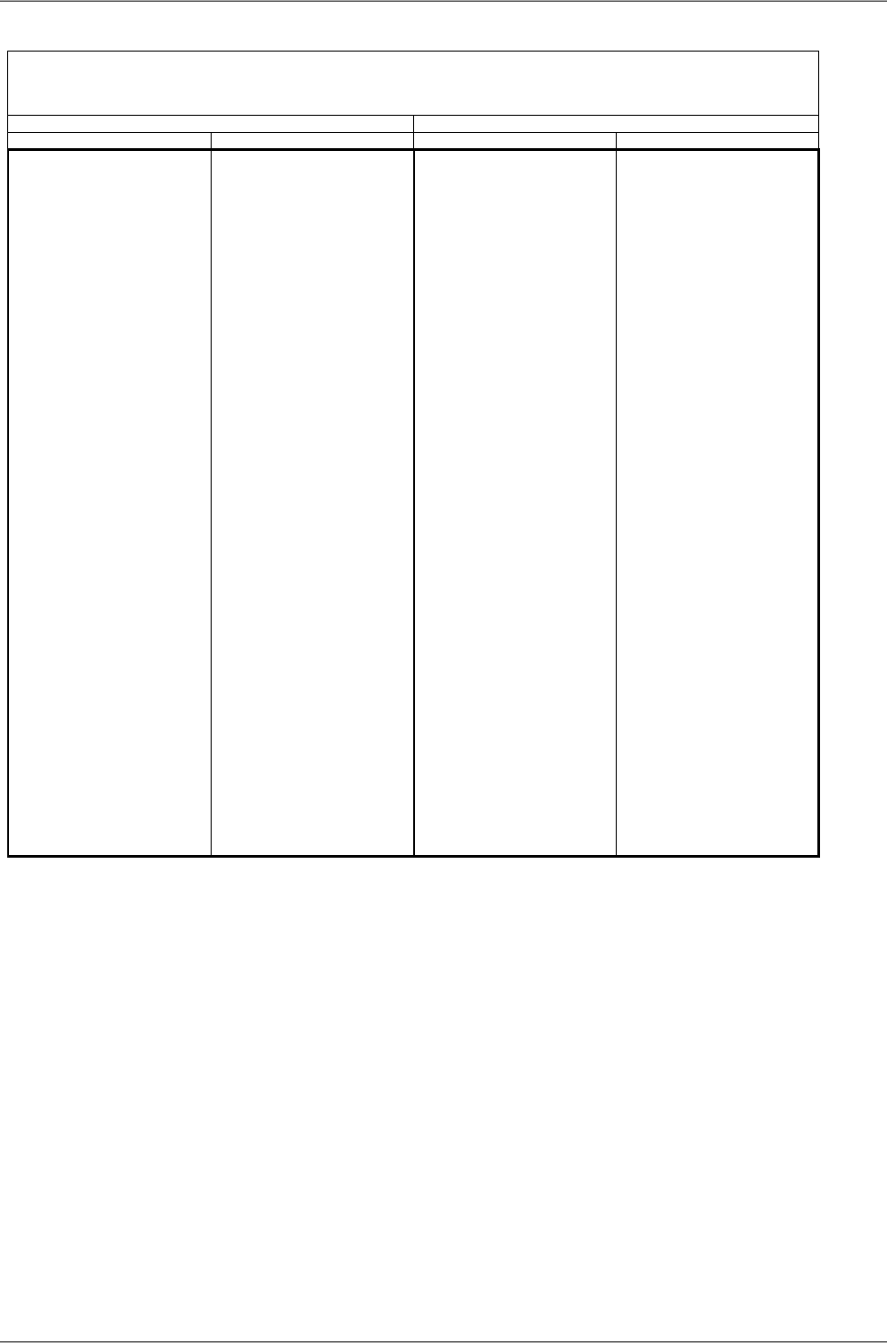
TX channel nominal frequencies
Band 17.7 – 19.7 GHz, duplex spacing 1010 MHz
Bandwidth: 7 MHz ITU-R F.595-10, Annex 5.a
( Freq.table: rcinfo18_A_default:5 ) ( Freq.table: rcinfo18_B_default:5 )
Ch.No. Lower [MHz] Upper [MHz] Ch.No. Lower [MHz] Upper [MHz] Ch.No. Lower [MHz] Upper [MHz] Ch.No. Lower [MHz] Upper [MHz]
1 17710.0 18720.0 37 17962.0 18972.0 67 18172.0 19182.0 104 18431 19441.0
2 17717.0 18727.0 38 17969.0 18979.0 68 18179.0 19189.0 105 18438 19448.0
3 17724.0 18734.0 39 17976.0 18986.0 69 18186.0 19196.0 106 18445 19455.0
4 17731.0 18741.0 40 17983.0 18993.0 70 18193.0 19203.0 107 18452 19462.0
5 17738.0 18748.0 41 17990.0 19000.0 71 18200.0 19210.0 108 18459 19469.0
6 17745.0 18755.0 42 17997.0 19007.0 72 18207.0 19217.0 109 18466 19476.0
7 17752.0 18762.0 43 18004.0 19014.0 73 18214.0 19224.0 110 18473 19483.0
8 17759.0 18769.0 44 18011.0 19021.0 74 18221.0 19231.0 111 18480 19490.0
9 17766.0 18776.0 45 18018.0 19028.0 75 18228.0 19238.0 112 18487 19497.0
10 17773.0 18783.0 46 18025.0 19035.0 76 18235.0 19245.0 113 18494 19504.0
11 17780.0 18790.0 47 18032.0 19042.0 77 18242.0 19252.0 114 18501 19511.0
12 17787.0 18797.0 48 18039.0 19049.0 78 18249.0 19259.0 115 18508 19518.0
13 17794.0 18804.0 49 18046.0 19056.0 79 18256.0 19266.0 116 18515 19525.0
14 17801.0 18811.0 50 18053.0 19063.0 80 18263.0 19273.0 117 18522 19532.0
15 17808.0 18818.0 51 18060.0 19070.0 81 18270.0 19280.0 118 18529 19539.0
16 17815.0 18825.0 52 18067.0 19077.0 82 18277.0 19287.0 119 18536 19546.0
17 17822.0 18832.0 53 18074.0 19084.0 83 18284.0 19294.0 120 18543 19553.0
18 17829.0 18839.0 54 18081.0 19091.0 84 18291.0 19301.0 121 18550 19560.0
19 17836.0 18846.0 55 18088.0 19098.0 85 18298.0 19308.0 122 18557 19567.0
20 17843.0 18853.0 56 18095.0 19105.0 86 18305.0 19315.0 123 18564 19574.0
21 17850.0 18860.0 57 18102.0 19112.0 87 18312.0 19322.0 124 18571 19581.0
22 17857.0 18867.0 58 18109.0 19119.0 88 18319.0 19329.0 125 18578 19588.0
23 17864.0 18874.0 59 18116.0 19126.0 89 18326.0 19336.0 126 18585 19595.0
24 17871.0 18881.0 60 18123.0 19133.0 90 18333.0 19343.0 127 18592 19602.0
25 17878.0 18888.0 61 18130.0 19140.0 91 18340.0 19350.0 128 18599 19609.0
26 17885.0 18895.0 62 18137.0 19147.0 92 18347.0 19357.0 129 18606 19616.0
27 17892.0 18902.0 63 18144.0 19154.0 93 18354.0 19364.0 130 18613 19623.0
28 17899.0 18909.0 64 18151.0 19161.0 94 18361.0 19371.0 131 18620 19630.0
29 17906.0 18916.0 65 18158.0 19168.0 95 18368.0 19378.0 132 18627 19637.0
30 17913.0 18923.0 66 18165.0 19175.0 96 18375.0 19385.0 133 18634 19644.0
31 17920.0 18930.0 67 18172.0 19182.0 97 18382.0 19392.0 134 18641 19651.0
32 17927.0 18937.0 68 18179.0 19189.0 98 18389.0 19399.0 135 18648 19658.0
33 17934.0 18944.0 69 18186.0 19196.0 99 18396.0 19406.0 136 18655 19665.0
34 17941.0 18951.0 70 18193.0 19203.0 100 18403.0 19413.0 137 18662 19672.0
35 17948.0 18958.0 71 18200.0 19210.0 101 18410.0 19420.0 138 18669 19679.0
36 17955.0 18965.0 102 18417.0 19427.0 139 18676 19686.0
37 17962.0 18972.0 103 18424.0 19434.0 140 18683 19693.0
38 17969.0 18979.0 104 18431.0 19441.0
39 17976.0 18986.0 105 18438.0 19448.0 Ver. 1.0
RAy2-18 - xA, RAy2-18 - xB
A sub-band
B sub-band
RAy2 Microwave Link – © RACOM s.r.o.228
Technical parameters
TX channel nominal frequencies
Band 17.7 – 19.7 GHz, duplex spacing 1008 MHz
Bandwidth: 7 MHz (1008) ITU-R F.595-9 -10, Annex 3
( Freq.table: rcinfo18_A_default:5 ) ( Freq.table: rcinfo18_B_default:5 )
Ch.No. Lower [MHz] Upper [MHz] Ch.No. Lower [MHz] Upper [MHz] Ch.No. Lower [MHz] Upper [MHz] Ch.No. Lower [MHz] Upper [MHz]
1 17724.0 18732.0 36 17969.0 18977.0 66 18179.0 19187.0 103 18438 19446.0
2 17731.0 18739.0 37 17976.0 18984.0 67 18186.0 19194.0 104 18445 19453.0
3 17738.0 18746.0 38 17983.0 18991.0 68 18193.0 19201.0 105 18452 19460.0
4 17745.0 18753.0 39 17990.0 18998.0 69 18200.0 19208.0 106 18459 19467.0
5 17752.0 18760.0 40 17997.0 19005.0 70 18207.0 19215.0 107 18466 19474.0
6 17759.0 18767.0 41 18004.0 19012.0 71 18214.0 19222.0 108 18473 19481.0
7 17766.0 18774.0 42 18011.0 19019.0 72 18221.0 19229.0 109 18480 19488.0
8 17773.0 18781.0 43 18018.0 19026.0 73 18228.0 19236.0 110 18487 19495.0
9 17780.0 18788.0 44 18025.0 19033.0 74 18235.0 19243.0 111 18494 19502.0
10 17787.0 18795.0 45 18032.0 19040.0 75 18242.0 19250.0 112 18501 19509.0
11 17794.0 18802.0 46 18039.0 19047.0 76 18249.0 19257.0 113 18508 19516.0
12 17801.0 18809.0 47 18046.0 19054.0 77 18256.0 19264.0 114 18515 19523.0
13 17808.0 18816.0 48 18053.0 19061.0 78 18263.0 19271.0 115 18522 19530.0
14 17815.0 18823.0 49 18060.0 19068.0 79 18270.0 19278.0 116 18529 19537.0
15 17822.0 18830.0 50 18067.0 19075.0 80 18277.0 19285.0 117 18536 19544.0
16 17829.0 18837.0 51 18074.0 19082.0 81 18284.0 19292.0 118 18543 19551.0
17 17836.0 18844.0 52 18081.0 19089.0 82 18291.0 19299.0 119 18550 19558.0
18 17843.0 18851.0 53 18088.0 19096.0 83 18298.0 19306.0 120 18557 19565.0
19 17850.0 18858.0 54 18095.0 19103.0 84 18305.0 19313.0 121 18564 19572.0
20 17857.0 18865.0 55 18102.0 19110.0 85 18312.0 19320.0 122 18571 19579.0
21 17864.0 18872.0 56 18109.0 19117.0 86 18319.0 19327.0 123 18578 19586.0
22 17871.0 18879.0 57 18116.0 19124.0 87 18326.0 19334.0 124 18585 19593.0
23 17878.0 18886.0 58 18123.0 19131.0 88 18333.0 19341.0 125 18592 19600.0
24 17885.0 18893.0 59 18130.0 19138.0 89 18340.0 19348.0 126 18599 19607.0
25 17892.0 18900.0 60 18137.0 19145.0 90 18347.0 19355.0 127 18606 19614.0
26 17899.0 18907.0 61 18144.0 19152.0 91 18354.0 19362.0 128 18613 19621.0
27 17906.0 18914.0 62 18151.0 19159.0 92 18361.0 19369.0 129 18620 19628.0
28 17913.0 18921.0 63 18158.0 19166.0 93 18368.0 19376.0 130 18627 19635.0
29 17920.0 18928.0 64 18165.0 19173.0 94 18375.0 19383.0 131 18634 19642.0
30 17927.0 18935.0 65 18172.0 19180.0 95 18382.0 19390.0 132 18641 19649.0
31 17934.0 18942.0 66 18179.0 19187.0 96 18389.0 19397.0 133 18648 19656.0
32 17941.0 18949.0 67 18186.0 19194.0 97 18396.0 19404.0 134 18655 19663.0
33 17948.0 18956.0 68 18193.0 19201.0 98 18403.0 19411.0 135 18662 19670.0
34 17955.0 18963.0 69 18200.0 19208.0 99 18410.0 19418.0 136 18669 19677.0
35 17962.0 18970.0 100 18417.0 19425.0 137 18676 19684.0
36 17969.0 18977.0 101 18424.0 19432.0 138 18683 19691.0
37 17976.0 18984.0 102 18431.0 19439.0
38 17983.0 18991.0 103 18438.0 19446.0
39 17990.0 18998.0 104 18445.0 19453.0 Ver. 1.0
RAy2-18 - xA, RAy2-18 - xB
A sub-band
B sub-band
229© RACOM s.r.o. – RAy2 Microwave Link
Technical parameters
TX channel nominal frequencies
Band 17.7 – 19.7 GHz, duplex spacing 1010 MHz
Bandwidth: 7.5 MHz ITU-R F.595-10, Annex 4.2
( Freq.table: rcinfo18_A_default:5 ) ( Freq.table: rcinfo18_B_default:5 )
Ch.No. Lower [MHz] Upper [MHz] Ch.No. Lower [MHz] Upper [MHz] Ch.No. Lower [MHz] Upper [MHz] Ch.No. Lower [MHz] Upper [MHz]
1 17710.0 18720.0 36 17972.5 18982.5 63 18175.0 19185.0 98 18437.5 19447.5
2 17717.5 18727.5 37 17980.0 18990.0 64 18182.5 19192.5 99 18445.0 19455.0
3 17725.0 18735.0 38 17987.5 18997.5 65 18190.0 19200.0 100 18452.5 19462.5
4 17732.5 18742.5 39 17995.0 19005.0 66 18197.5 19207.5 101 18460.0 19470.0
5 17740.0 18750.0 40 18002.5 19012.5 67 18205.0 19215.0 102 18467.5 19477.5
6 17747.5 18757.5 41 18010.0 19020.0 68 18212.5 19222.5 103 18475.0 19485.0
7 17755.0 18765.0 42 18017.5 19027.5 69 18220.0 19230.0 104 18482.5 19492.5
8 17762.5 18772.5 43 18025.0 19035.0 70 18227.5 19237.5 105 18490.0 19500.0
9 17770.0 18780.0 44 18032.5 19042.5 71 18235.0 19245.0 106 18497.5 19507.5
10 17777.5 18787.5 45 18040.0 19050.0 72 18242.5 19252.5 107 18505.0 19515.0
11 17785.0 18795.0 46 18047.5 19057.5 73 18250.0 19260.0 108 18512.5 19522.5
12 17792.5 18802.5 47 18055.0 19065.0 74 18257.5 19267.5 109 18520.0 19530.0
13 17800.0 18810.0 48 18062.5 19072.5 75 18265.0 19275.0 110 18527.5 19537.5
14 17807.5 18817.5 49 18070.0 19080.0 76 18272.5 19282.5 111 18535.0 19545.0
15 17815.0 18825.0 50 18077.5 19087.5 77 18280.0 19290.0 112 18542.5 19552.5
16 17822.5 18832.5 51 18085.0 19095.0 78 18287.5 19297.5 113 18550.0 19560.0
17 17830.0 18840.0 52 18092.5 19102.5 79 18295.0 19305.0 114 18557.5 19567.5
18 17837.5 18847.5 53 18100.0 19110.0 80 18302.5 19312.5 115 18565.0 19575.0
19 17845.0 18855.0 54 18107.5 19117.5 81 18310.0 19320.0 116 18572.5 19582.5
20 17852.5 18862.5 55 18115.0 19125.0 82 18317.5 19327.5 117 18580.0 19590.0
21 17860.0 18870.0 56 18122.5 19132.5 83 18325.0 19335.0 118 18587.5 19597.5
22 17867.5 18877.5 57 18130.0 19140.0 84 18332.5 19342.5 119 18595.0 19605.0
23 17875.0 18885.0 58 18137.5 19147.5 85 18340.0 19350.0 120 18602.5 19612.5
24 17882.5 18892.5 59 18145.0 19155.0 86 18347.5 19357.5 121 18610.0 19620.0
25 17890.0 18900.0 60 18152.5 19162.5 87 18355.0 19365.0 122 18617.5 19627.5
26 17897.5 18907.5 61 18160.0 19170.0 88 18362.5 19372.5 123 18625.0 19635.0
27 17905.0 18915.0 62 18167.5 19177.5 89 18370.0 19380.0 124 18632.5 19642.5
28 17912.5 18922.5 63 18175.0 19185.0 90 18377.5 19387.5 125 18640.0 19650.0
29 17920.0 18930.0 64 18182.5 19192.5 91 18385.0 19395.0 126 18647.5 19657.5
30 17927.5 18937.5 65 18190.0 19200.0 92 18392.5 19402.5 127 18655.0 19665.0
31 17935.0 18945.0 66 18197.5 19207.5 93 18400.0 19410.0 128 18662.5 19672.5
32 17942.5 18952.5 67 18205.0 19215.0 94 18407.5 19417.5 129 18670.0 19680.0
33 17950.0 18960.0 95 18415.0 19425.0 130 18677.5 19687.5
34 17957.5 18967.5 96 18422.5 19432.5 131 18685.0 19695.0
35 17965.0 18975.0 97 18430.0 19440.0
36 17972.5 18982.5 98 18437.5 19447.5
37 17980.0 18990.0 99 18445.0 19455.0 Ver. 1.0
RAy2-18 - xA, RAy2-18 - xB
A sub-band
B sub-band
RAy2 Microwave Link – © RACOM s.r.o.230
Technical parameters

TX channel nominal frequencies
Band 17.7 – 19.7 GHz, duplex spacing 1010 MHz
Bandwidth: 13.75 MHz CEPT 12-03 E, Annex A, ITU-R F.595-9 -10, Annex 4 (6.a)
( Freq.table: rcinfo18_A_default:5 ) ( Freq.table: rcinfo18_B_default:5 )
Ch.No. Lower [MHz] Upper [MHz] Ch.No. Lower [MHz] Upper [MHz]
1 17713.75 18723.75 35 18181.25 19191.25
2 17727.50 18737.50 36 18195.00 19205.00
3 17741.25 18751.25 37 18208.75 19218.75
4 17755.00 18765.00 38 18222.50 19232.50
5 17768.75 18778.75 39 18236.25 19246.25
6 17782.50 18792.50 40 18250.00 19260.00
7 17796.25 18806.25 41 18263.75 19273.75
8 17810.00 18820.00 42 18277.50 19287.50
9 17823.75 18833.75 43 18291.25 19301.25
10 17837.50 18847.50 44 18305.00 19315.00
11 17851.25 18861.25 45 18318.75 19328.75
12 17865.00 18875.00 46 18332.50 19342.50
13 17878.75 18888.75 47 18346.25 19356.25
14 17892.50 18902.50 48 18360.00 19370.00
15 17906.25 18916.25 49 18373.75 19383.75
16 17920.00 18930.00 50 18387.50 19397.50
17 17933.75 18943.75 51 18401.25 19411.25
18 17947.50 18957.50 52 18415.00 19425.00
19 17961.25 18971.25 53 18428.75 19438.75
20 17975.00 18985.00 54 18442.50 19452.50
21 17988.75 18998.75 55 18456.25 19466.25
22 18002.50 19012.50 56 18470.00 19480.00
23 18016.25 19026.25 57 18483.75 19493.75
24 18030.00 19040.00 58 18497.50 19507.50
25 18043.75 19053.75 59 18511.25 19521.25
26 18057.50 19067.50 60 18525.00 19535.00
27 18071.25 19081.25 61 18538.75 19548.75
28 18085.00 19095.00 62 18552.50 19562.50
29 18098.75 19108.75 63 18566.25 19576.25
30 18112.50 19122.50 64 18580.00 19590.00
31 18126.25 19136.25 65 18593.75 19603.75
32 18140.00 19150.00 66 18607.50 19617.50
33 18153.75 19163.75 67 18621.25 19631.25
34 18167.50 19177.50 68 18635.00 19645.00
35 18181.25 19191.25 69 18648.75 19658.75
36 18195.00 19205.00 70 18662.50 19672.50
71 18676.25 19686.25
Ver. 1.0
RAy2-18 - xA, RAy2-18 - xB
A sub-band B sub-band
231© RACOM s.r.o. – RAy2 Microwave Link
Technical parameters
TX channel nominal frequencies
Band 17.7 – 19.7 GHz, duplex spacing 1010 MHz
Bandwidth: 27.5 MHz CEPT 12-03 E, Annex A, ITU-R F.595-9 -10, rec. 1.1.3
( Freq.table: rcinfo18_A_default:5 ) ( Freq.table: rcinfo18_B_default:5 )
Ch.No. Lower [MHz] Upper [MHz] Ch.No. Lower [MHz] Upper [MHz]
1 17728 18738 18 18195 19205
2 17755 18765 19 18223 19233
3 17783 18793 20 18250 19260
4 17810 18820 21 18278 19288
5 17838 18848 22 18305 19315
6 17865 18875 23 18333 19343
7 17893 18903 24 18360 19370
8 17920 18930 25 18388 19398
9 17948 18958 26 18415 19425
10 17975 18985 27 18443 19453
11 18003 19013 28 18470 19480
12 18030 19040 29 18498 19508
13 18058 19068 30 18525 19535
14 18085 19095 31 18553 19563
15 18113 19123 32 18580 19590
16 18140 19150 33 18608 19618
17 18168 19178 34 18635 19645
18 18195 19205 35 18663 19673
Ver. 1.0
RAy2-18 - xA, RAy2-18 - xB
A sub-band B sub-band
TX channel nominal frequencies
Band 17.7 – 19.7 GHz, duplex spacing 1010 MHz
Bandwidth: 55 MHz CEPT 12-03 E, Annex A, ITU-R F.595-9 -10, rec. 1.1.4
( Freq.table: rcinfo18_A_default:5 ) ( Freq.table: rcinfo18_B_default:5 )
Ch.No. Lower [MHz] Upper [MHz] Ch.No. Lower [MHz] Upper [MHz]
1 17755 18765 9 18195 19205
2 17810 18820 10 18250 19260
3 17865 18875 11 18305 19315
4 17920 18930 12 18360 19370
5 17975 18985 13 18415 19425
6 18030 19040 14 18470 19480
7 18085 19095 15 18525 19535
8 18140 19150 16 18580 19590
17 18635 19645
Ver. 1.0
RAy2-18 - xA, RAy2-18 - xB
A sub-band B sub-band
TX channel nominal frequencies
Band 17.7 – 19.7 GHz, duplex spacing 1010 MHz
Bandwidth:
55 MHz (Indonesia)
ITU-R F.595-9 -10, Annex 6
( Freq.table: rcinfo18_A_default:5 ) ( Freq.table: rcinfo18_B_default:5 )
Ch.No. Lower [MHz] Upper [MHz] Ch.No. Lower [MHz] Upper [MHz]
1 18332.5 19342.5
2 18387.5 19397.5
3 18442.5 19452.5
4 18497.5 19507.5
5 18552.5 19562.5
6 18607.5 19617.5
7 18662.5 19672.5
Ver. 1.0
RAy2-18 - xA, RAy2-18 - xB
A sub-band B sub-band
RAy2 Microwave Link – © RACOM s.r.o.232
Technical parameters

10.8. RAy2-24 parameters
10.8.1. Upper/Lower Limits
TX powerRAy2-24
MaxMin
Modulation [dBm][dBm]
10-30QPSK
10-3016-QAM
10-3032-QAM
10-3064-QAM
10-30128-QAM
10-30256-QAM
ver. 1.0
Minimum (hw limit) and default duplex spacing.
Optional duplex spacingRAy2-24
defaultminChannel width
[MHz][MHz][MHz]
73.5603.5
73.5607
87.56514
847028
707040
87.58450
848456
ver. 2.6
Band RangeRAy2-24
Unit UUnit L
[MHz][MHz]
24.00024.000min
24.25024.250max
ver. 1.0
233© RACOM s.r.o. – RAy2 Microwave Link
Technical parameters
10.8.2. Radio parameters
Channel spacing 3.5 MHz; ACCP operationRAy2-24
Adjacent channel SelectivityCo-channel rejection
RSS / SNR for
BER 10-6
User
Bit
Rate
Raw
Bit
Rate
Modula-
tion
3 dB1 dB3 dB1 dB
declared / limitdeclared / limitdeclared / limitdeclared / limitSNRRSS
[dB][dB][dB][dB][dB][dBm][Mbps][-]
-4/-160/-1419/1223/159.5-964.96QPSK
-7/-15-3/-1326.5/2030/2215.0-899.61216-QAM
-7/-14-3/-1226.5/2230/2418.5-8612.11532-QAM
-7/-12-3/-1126.5/2630/2920.5-8314.31864-QAM
-7/-8-3/-926.5/2830/3023.5-7917.221128-QAM
-7/-7-3/-526.5/3130/3326.0-7719.724256-QAM
ver. 1.0
Channel spacing 7 MHz; ACCP operationRAy2-24
Adjacent channel SelectivityCo-channel rejection
RSS / SNR for
BER 10-6
User
Bit
Rate
Raw
Bit
Rate
Modula-
tion
3 dB1 dB3 dB1 dB
declared / limitdeclared / limitdeclared / limitdeclared / limitSNRRSS
[dB][dB][dB][dB][dB][dBm][Mbps][-]
-4/-220/-2019/1223/158.5-938.512QPSK
-7/-19-3/-1826.5/2030/2215.0-8617.22416-QAM
-6/-18-2/-1633/2237/2418.5-8322.13032-QAM
-6/-16-2/-1433/2637/2921.5-7929.73664-QAM
-6/-14-2/-1233/3037/3225.0-7634.742128-QAM
-6/-12-2/-1033/3137/3326.0-7440.749256-QAM
ver. 1.0
RAy2 Microwave Link – © RACOM s.r.o.234
Technical parameters

Channel spacing 14 MHz; ACCP operationRAy2-24
Adjacent channel SelectivityCo-channel rejection
RSS / SNR for
BER 10-6
User
Bit
Rate
Raw
Bit
Rate
Modula-
tion
3 dB1 dB3 dB1 dB
declared / limitdeclared / limitdeclared / limitdeclared / limitSNRRSS
[dB][dB][dB][dB][dB][dBm][Mbps][-]
-4/-230/-2119/1223/148.5-9119.924QPSK
-7/-21-3/-1926.5/1830/2015.0-8438.84816-QAM
-9/-19-5/-1729/2333/2618.5-8049.16032-QAM
-6/-17-2/-1433/2637/2821.5-7762.37264-QAM
-6/-14-2/-1233/2837/3025.0-7373.684128-QAM
-6/-12-2/-1033/3137/3328.0-7181.296256-QAM
ver. 1.0
Channel spacing 28 MHz; ACCP operationRAy2-24
Adjacent channel SelectivityCo-channel rejection
RSS / SNR for
BER 10-6
User
Bit
Rate
Raw
Bit
Rate
Modula-
tion
3 dB1 dB3 dB1 dB
declared / limitdeclared / limitdeclared / limitdeclared / limitSNRRSS
[dB][dB][dB][dB][dB][dBm][Mbps][-]
-4/-230/-2119/1023/127.5-8936.850QPSK
-7/-20-3/-1826.5/1830/2015.0-8280.910016-QAM
-9/-19-5/-1629/2233/2418.5-78102.412532-QAM
-8/-15-5/-1232/2635/2821.5-75129.815064-QAM
-8/-12-5/-932/2835/3025.0-71155.5175128-QAM
-8/-9-5/-632/3135/3326.5-68170.7200256-QAM
ver. 1.0
Channel spacing 40 MHz; ACCP operationRAy2-24
Adjacent channel SelectivityCo-channel rejection
RSS / SNR for
BER 10-6
User
Bit
Rate
Raw
Bit
Rate
Modula-
tion
3 dB1 dB3 dB1 dB
declared / limitdeclared / limitdeclared / limitdeclared / limitSNRRSS
[dB][dB][dB][dB][dB][dBm][Mbps][-]
-8/-24-4/-2229/1033/127.5-8750.168QPSK
-8/-21-4/-1829/1733/1915.0-80110.013616-QAM
-8/-19-4/-1629/2133/2418.5-76139.217032-QAM
-8/-16-4/-1429/2533/2721.5-73176.520464-QAM
-8/-12-4/-1033/2837/3025.0-69211.4238128-QAM
-8/-10-4/-833/3037/3326.5-67232.1272256-QAM
ver. 1.1
235© RACOM s.r.o. – RAy2 Microwave Link
Technical parameters

Channel spacing 50 MHz; ACCP operationRAy2-24
Adjacent channel SelectivityCo-channel rejection
RSS / SNR for
BER 10-6
User
Bit
Rate
Raw
Bit
Rate
Modula-
tion
3 dB1 dB3 dB1 dB
declared / limitdeclared / limitdeclared / limitdeclared / limitSNRRSS
[dB][dB][dB][dB][dB][dBm][Mbps][-]
-4/-260/-2419/1023/127.5-86.566.390QPSK
-7/-21-3/-1826.5/1730/1915.0-79.5145.618016-QAM
-9/-19-5/-1629/2233/2418.5-75.5184.222532-QAM
-8/-16-5/-1432/2535/2721.5-72.5233.627064-QAM
-8/-12-5/-1032/2835/3025.0-68.5276.1315128-QAM
-8/-10-5/-832/3035/3326.5-65.5320.6360256-QAM
ver. 1.0
Channel spacing 56 MHz; ACCP operationRAy2-24
Adjacent channel SelectivityCo-channel rejection
RSS / SNR for
BER 10-6
User
Bit
Rate
Raw
Bit
Rate
Modula-
tion
3 dB1 dB3 dB1 dB
declared / limitdeclared / limitdeclared / limitdeclared / limitSNRRSS
[dB][dB][dB][dB][dB][dBm][Mbps][-]
-4/-280/-2619/1023/127.5-8672.999QPSK
-7/-21-3/-1926.5/1730/1915.0-79160.219816-QAM
-9/-17-5/-1529/2233/2418.5-75202.7247.532-QAM
-8/-16-5/-1432/2535/2721.5-72256.929764-QAM
-8/-12-5/-1032/2835/3025.0-68303.7346.5128-QAM
-8/-10-5/-832/3035/3326.5-65337.7396256-QAM
ver. 1.0
Channel spacing 56 MHz TO; ACCP operationRAy2-24
Adjacent channel SelectivityCo-channel rejection
RSS / SNR for
BER 10-6
User
Bit
Rate
Raw
Bit
Rate
Modula-
tion
3 dB1 dB3 dB1 dB
declared / limitdeclared / limitdeclared / limitdeclared / limitSNRRSS
[dB][dB][dB][dB][dB][dBm][Mbps][-]
-4/-260/-2419/1123/1310.0-8485.899QPSK
-7/-20-3/-1826.5/1830/2016.0-77169.919816-QAM
-9/-15-5/-1429/2333/2519.0-73206.2247.532-QAM
-8/-11-5/-932/2635/2922.5-69268.129764-QAM
-8/-10-5/-832/2935/3225.5-66309.0346.5128-QAM
-8/-8-5/-732/3235/3527.5-63358.9396256-QAM
ver. 1.1
RAy2 Microwave Link – © RACOM s.r.o.236
Technical parameters

10.8.3. Nominal frequencies 24.00-24.25 GHz
RAy2-24 TX channel nominal frequencies
Band 24.00 – 24.25 GHz, duplex spacing 73.5 MHz
Bandwidth: 3.5 MHz duplex spacing range 63 – 238 MHz
(Freq.table: rcinfo24_ISM250_default:14)
basic channels (default duplex) optional channels
Ch.No. Lower [MHz] Ch.No. Upper [MHz] Ch.No. Lower [MHz] Ch.No. Upper [MHz]
###
U19 24069.0
no more channels
U20 24072.5
U21 24076.0
L1
24006.0
U22 24079.5
L2
24009.5
U23 24083.0
L3
24013.0
U24 24086.5
L4
24016.5
U25 24090.0
L5
24020.0
U26 24093.5
L6
24023.5
U27 24097.0
L7
24027.0
U28 24100.5
L8
24030.5
U29 24104.0
L9
24034.0
U30 24107.5
L10
24037.5
U31 24111.0
L11
24041.0
U32 24114.5
L12
24044.5
U33 24118.0
###
L13
24048.0
U34 24121.5
###
L14
24051.5
U35 24125.0
###
L15
24055.0
U36 24128.5
###
L16
24058.5
U37 24132.0
###
L17
24062.0
U38 24135.5
###
L18
24065.5
U39 24139.0
###
L19
24069.0
U40 24142.5
###
L20
24072.5
U41 24146.0
###
L21
24076.0
U42 24149.5
###
L22
24079.5
U43 24153.0
###
L23
24083.0
U44 24156.5
###
L24
24086.5
U45 24160.0
###
L25
24090.0
U46 24163.5
###
L26
24093.5
U47 24167.0
###
L27
24097.0
U48 24170.5
###
L28
24100.5
U49 24174.0
###
L29
24104.0
U50 24177.5
###
L30
24107.5
U51 24181.0
###
L31
24111.0
U52 24184.5
###
L32
24114.5
U53 24188.0
###
L33
24118.0
U54 24191.5
###
L34
24121.5
U55 24195.0
###
L35
24125.0
U56 24198.5
###
L36
24128.5
U57 24202.0
###
L37
24132.0
U58 24205.5
L38
24135.5
U59 24209.0
L39
24139.0
U60 24212.5
L40
24142.5
U61 24216.0
L41
24146.0
U62 24219.5
L42
24149.5
U63 24223.0
L43
24153.0
U64 24226.5
L44
24156.5
U65 24230.0
L45
24160.0
U66 24233.5
L46
24163.5
U67 24237.0
L47
24167.0
U68 24240.5
L48
24170.5
U69 24244.0
L49
24174.0
L50
24177.5
L51
24181.0
ver. 2.2
237© RACOM s.r.o. – RAy2 Microwave Link
Technical parameters

RAy2-24 TX channel nominal frequencies
Band 24.00 – 24.25 GHz, duplex spacing 73.5 MHz
Bandwidth: 7 MHz duplex spacing range 63 – 238 MHz
(Freq.table: rcinfo24_ISM250_default:14)
basic channels (default duplex) optional channels
Ch.No. Lower [MHz] Ch.No. Upper [MHz] Ch.No. Lower [MHz] Ch.No. Upper [MHz]
U19 24069.0
U20 24072.5
U21 24076.0
L1 24006.0 U22 24079.5
L2 24009.5 U23 24083.0
L3 24013.0 U24 24086.5
L4 24016.5 U25 24090.0
L5 24020.0 U26 24093.5
L6 24023.5 U27 24097.0
L7 24027.0 U28 24100.5
L8 24030.5 U29 24104.0
L9 24034.0 U30 24107.5
L10 24037.5 U31 24111.0
L11 24041.0 U32 24114.5
L12 24044.5 U33 24118.0
L13 24048.0 U34 24121.5
L14 24051.5 U35 24125.0
L15 24055.0 U36 24128.5
L16 24058.5 U37 24132.0
L17 24062.0 U38 24135.5
L18 24065.5 U39 24139.0
L19 24069.0 U40 24142.5
L20 24072.5 U41 24146.0
L21 24076.0 U42 24149.5
L22 24079.5 U43 24153.0
L23 24083.0 U44 24156.5
L24 24086.5 U45 24160.0
L25 24090.0 U46 24163.5
L26 24093.5 U47 24167.0
L27 24097.0 U48 24170.5
L28 24100.5 U49 24174.0
L29 24104.0 U50 24177.5
L30 24107.5 U51 24181.0
L31 24111.0 U52 24184.5
L32 24114.5 U53 24188.0
L33 24118.0 U54 24191.5
L34 24121.5 U55 24195.0
L35 24125.0 U56 24198.5
L36 24128.5 U57 24202.0
L37 24132.0 U58 24205.5
L38 24135.5 U59 24209.0
L39 24139.0 U60 24212.5
L40 24142.5 U61 24216.0
L41 24146.0 U62 24219.5
L42 24149.5 U63 24223.0
L43 24153.0 U64 24226.5
L44 24156.5 U65 24230.0
L45 24160.0 U66 24233.5
L46 24163.5 U67 24237.0
L47 24167.0 U68 24240.5
L48 24170.5 U69 24244.0
L49 24174.0
L50 24177.5
L51 24181.0
ver. 2.1
RAy2 Microwave Link – © RACOM s.r.o.238
Technical parameters

RAy2-24 TX channel nominal frequencies
Band 24.00 – 24.25 GHz, duplex spacing 87.5 MHz
Bandwidth: 14 MHz duplex spacing range 66.5 – 231 MHz
(Freq.table: rcinfo24_ISM250_default:14)
basic channels (default duplex) optional channels
Ch.No. Lower [MHz] Ch.No. Upper [MHz] Ch.No. Lower [MHz] Ch.No. Upper [MHz]
###
###
###
###
U21 24076.0
###
###
U22 24079.5
###
###
U23 24083.0
###
U24 24086.5
###
###
###
U25 24090.0
###
U26 24093.5
###
L2 24009.5 U27 24097.0
L3 24013.0 U28 24100.5
###
###
L4 24016.5 U29 24104.0
###
L5 24020.0 U30 24107.5
###
L6 24023.5 U31 24111.0
L7 24027.0 U32 24114.5
###
###
L8 24030.5 U33 24118.0
###
L9 24034.0 U34 24121.5
###
L10 24037.5 U35 24125.0
L11 24041.0 U36 24128.5
###
###
L12 24044.5 U37 24132.0
###
L13 24048.0 U38 24135.5
###
L14 24051.5 U39 24139.0
L15 24055.0 U40 24142.5
###
###
L16 24058.5 U41 24146.0
###
L17 24062.0 U42 24149.5
###
L18 24065.5 U43 24153.0
L19 24069.0 U44 24156.5
###
###
L20 24072.5 U45 24160.0
###
L21 24076.0 U46 24163.5
###
L22 24079.5 U47 24167.0
L23 24083.0 U48 24170.5
###
###
L24 24086.5 U49 24174.0
###
L25 24090.0 U50 24177.5
###
L26 24093.5 U51 24181.0
L27 24097.0 U52 24184.5
###
###
L28 24100.5 U53 24188.0
###
L29 24104.0 U54 24191.5
###
L30 24107.5 U55 24195.0
L31 24111.0 U56 24198.5
###
###
L32 24114.5 U57 24202.0
###
L33 24118.0 U58 24205.5
###
L34 24121.5 U59 24209.0
L35 24125.0 U60 24212.5
###
###
L36 24128.5 U61 24216.0
###
L37 24132.0 U62 24219.5
###
L38 24135.5 U63 24223.0
L39 24139.0 U64 24226.5
###
###
L40 24142.5 U65 24230.0
###
L41 24146.0 U66 24233.5
###
L42 24149.5 U67 24237.0
L43 24153.0 U68 24240.5
###
###
L44 24156.5
###
L45 24160.0
###
L46 24163.5
L47 24167.0
###
###
L48 24170.5
###
L49 24174.0
ver. 2.1
239© RACOM s.r.o. – RAy2 Microwave Link
Technical parameters

RAy2-24 TX channel nominal frequencies
Band 24.00 – 24.25 GHz, duplex spacing 84 MHz
Bandwidth: 28 MHz duplex spacing range 70 – 217 MHz
(Freq.table: rcinfo24_ISM250_default:14)
basic channels (default duplex) optional channels
Ch.No. Lower [MHz] Ch.No. Upper [MHz] Ch.No. Lower [MHz] Ch.No. Upper [MHz]
U24 24086.5
U25 24090.0
U26 24093.5
U27 24097.0
L4 24016.5 U28 24100.5
L5 24020.0 U29 24104.0
L6 24023.5 U30 24107.5
L7 24027.0 U31 24111.0
L8 24030.5 U32 24114.5
L9 24034.0 U33 24118.0
L10 24037.5 U34 24121.5
L11 24041.0 U35 24125.0
L12 24044.5 U36 24128.5
L13 24048.0 U37 24132.0
L14 24051.5 U38 24135.5
L15 24055.0 U39 24139.0
L16 24058.5 U40 24142.5
L17 24062.0 U41 24146.0
L18 24065.5 U42 24149.5
L19 24069.0 U43 24153.0
L20 24072.5 U44 24156.5
L21 24076.0 U45 24160.0
L22 24079.5 U46 24163.5
L23 24083.0 U47 24167.0
L24 24086.5 U48 24170.5
L25 24090.0 U49 24174.0
L26 24093.5 U50 24177.5
L27 24097.0 U51 24181.0
L28 24100.5 U52 24184.5
L29 24104.0 U53 24188.0
L30 24107.5 U54 24191.5
L31 24111.0 U55 24195.0
L32 24114.5 U56 24198.5
L33 24118.0 U57 24202.0
L34 24121.5 U58 24205.5
L35 24125.0 U59 24209.0
L36 24128.5 U60 24212.5
L37 24132.0 U61 24216.0
L38 24135.5 U62 24219.5
L39 24139.0 U63 24223.0
L40 24142.5 U64 24226.5
L41 24146.0 U65 24230.0
L42 24149.5 U66 24233.5
L43 24153.0
L44 24156.5
L45 24160.0
L46 24163.5
ver. 2.1
RAy2 Microwave Link – © RACOM s.r.o.240
Technical parameters

RAy2-24 TX channel nominal frequencies
Band 24.00 – 24.25 GHz, duplex spacing 70 MHz
Bandwidth: 40 MHz duplex spacing range 70 – 203 MHz
(Freq.table: rcinfo24_ISM250_default:14)
basic channels (default duplex) optional channels
Ch.No. Lower [MHz] Ch.No. Upper [MHz] Ch.No. Lower [MHz] Ch.No. Upper [MHz]
L6 24023.5 U26 24093.5
L7 24027.0 U27 24097.0
L8 24030.5 U28 24100.5
L9 24034.0 U29 24104.0
L10 24037.5 U30 24107.5
L11 24041.0 U31 24111.0
L12 24044.5 U32 24114.5
L13 24048.0 U33 24118.0
L14 24051.5 U34 24121.5
L15 24055.0 U35 24125.0
L16 24058.5 U36 24128.5
L17 24062.0 U37 24132.0
L18 24065.5 U38 24135.5
L19 24069.0 U39 24139.0
L20 24072.5 U40 24142.5
L21 24076.0 U41 24146.0
L22 24079.5 U42 24149.5
L23 24083.0 U43 24153.0
L24 24086.5 U44 24156.5
L25 24090.0 U45 24160.0
L26 24093.5 U46 24163.5
L27 24097.0 U47 24167.0
L28 24100.5 U48 24170.5
L29 24104.0 U49 24174.0
L30 24107.5 U50 24177.5
L31 24111.0 U51 24181.0
L32 24114.5 U52 24184.5
L33 24118.0 U53 24188.0
L34 24121.5 U54 24191.5
L35 24125.0 U55 24195.0
L36 24128.5 U56 24198.5
L37 24132.0 U57 24202.0
L38 24135.5 U58 24205.5
L39 24139.0 U59 24209.0
L40 24142.5 U60 24212.5
L41 24146.0 U61 24216.0
L42 24149.5 U62 24219.5
L43 24153.0 U63 24223.0
L44 24156.5 U64 24226.5
ver. 2.1
241© RACOM s.r.o. – RAy2 Microwave Link
Technical parameters

RAy2-24 TX channel nominal frequencies
Band 24.00 – 24.25 GHz, duplex spacing 87.5 MHz
Bandwidth: 50 MHz duplex spacing range 84 – 196 MHz
(Freq.table: rcinfo24_ISM250_default:15)
basic channels (default duplex) optional channels
Ch.No. Lower [MHz] Ch.No. Upper [MHz] Ch.No. Lower [MHz] Ch.No. Upper [MHz]
U31 24111.0
L7 24027.0 U32 24114.5
L8 24030.5 U33 24118.0
L9 24034.0 U34 24121.5
L10 24037.5 U35 24125.0
L11 24041.0 U36 24128.5
L12 24044.5 U37 24132.0
L13 24048.0 U38 24135.5
L14 24051.5 U39 24139.0
L15 24055.0 U40 24142.5
L16 24058.5 U41 24146.0
L17 24062.0 U42 24149.5
L18 24065.5 U43 24153.0
L19 24069.0 U44 24156.5
L20 24072.5 U45 24160.0
L21 24076.0 U46 24163.5
L22 24079.5 U47 24167.0
L23 24083.0 U48 24170.5
L24 24086.5 U49 24174.0
L25 24090.0 U50 24177.5
L26 24093.5 U51 24181.0
L27 24097.0 U52 24184.5
L28 24100.5 U53 24188.0
L29 24104.0 U54 24191.5
L30 24107.5 U55 24195.0
L31 24111.0 U56 24198.5
L32 24114.5 U57 24202.0
L33 24118.0 U58 24205.5
L34 24121.5 U59 24209.0
L35 24125.0 U60 24212.5
L36 24128.5 U61 24216.0
L37 24132.0 U62 24219.5
L38 24135.5 U63 24223.0
L39 24139.0
ver. 1.0
RAy2 Microwave Link – © RACOM s.r.o.242
Technical parameters

RAy2-24 TX channel nominal frequencies
Band 24.00 – 24.25 GHz, duplex spacing 84 MHz
Bandwidth: 56 MHz duplex spacing range 84 – 189 MHz
(Freq.table: rcinfo24_ISM250_default:14)
basic channels (default duplex) optional channels
Ch.No. Lower [MHz] Ch.No. Upper [MHz] Ch.No. Lower [MHz] Ch.No. Upper [MHz]
###
###
L8 24030.5 U32 24114.5
L9 24034.0 U33 24118.0
L10 24037.5 U34 24121.5
L11 24041.0 U35 24125.0
L12 24044.5 U36 24128.5
L13 24048.0 U37 24132.0
L14 24051.5 U38 24135.5
L15 24055.0 U39 24139.0
L16 24058.5 U40 24142.5
L17 24062.0 U41 24146.0
L18 24065.5 U42 24149.5
L19 24069.0 U43 24153.0
L20 24072.5 U44 24156.5
L21 24076.0 U45 24160.0
L22 24079.5 U46 24163.5
L23 24083.0 U47 24167.0
L24 24086.5 U48 24170.5
L25 24090.0 U49 24174.0
L26 24093.5 U50 24177.5
L27 24097.0 U51 24181.0
L28 24100.5 U52 24184.5
L29 24104.0 U53 24188.0
L30 24107.5 U54 24191.5
L31 24111.0 U55 24195.0
L32 24114.5 U56 24198.5
L33 24118.0 U57 24202.0
L34 24121.5 U58 24205.5
L35 24125.0 U59 24209.0
L36 24128.5 U60 24212.5
L37 24132.0 U61 24216.0
L38 24135.5 U62 24219.5
ver. 2.1
243© RACOM s.r.o. – RAy2 Microwave Link
Technical parameters

10.8.4. Nominal frequencies 24.05-24.25 GHz
RAy2-24 TX channel nominal frequencies
Band 24.05 – 24.25 GHz, default duplex sp. 73.5 MHz
Bandwidth: 3.5 MHz duplex spacing range 63 – 189 MHz
(Freq.table: rcinfo24_ISM200:13)
basic channels (default duplex) optional channels
Ch.No. Lower [MHz] Ch.No. Upper [MHz] Ch.No. Lower [MHz] Ch.No. Upper [MHz]
###
U33 24118.0
###
no more channels
U34 24121.5
###
U35 24125.0
###
L15 24055.0 U36 24128.5
###
L16 24058.5 U37 24132.0
###
L17 24062.0 U38 24135.5
###
L18 24065.5 U39 24139.0
###
L19 24069.0 U40 24142.5
###
L20 24072.5 U41 24146.0
###
L21 24076.0 U42 24149.5
###
L22 24079.5 U43 24153.0
###
L23 24083.0 U44 24156.5
###
L24 24086.5 U45 24160.0
###
L25 24090.0 U46 24163.5
###
L26 24093.5 U47 24167.0
###
L27 24097.0 U48 24170.5
###
L28 24100.5 U49 24174.0
###
L29 24104.0 U50 24177.5
###
L30 24107.5 U51 24181.0
###
L31 24111.0 U52 24184.5
###
L32 24114.5 U53 24188.0
###
L33 24118.0 U54 24191.5
###
L34 24121.5 U55 24195.0
###
L35 24125.0 U56 24198.5
###
L36 24128.5 U57 24202.0
###
L37 24132.0 U58 24205.5
L38 24135.5 U59 24209.0
L39 24139.0 U60 24212.5
L40 24142.5 U61 24216.0
L41 24146.0 U62 24219.5
L42 24149.5 U63 24223.0
L43 24153.0 U64 24226.5
L44 24156.5 U65 24230.0
L45 24160.0 U66 24233.5
L46 24163.5 U67 24237.0
L47 24167.0 U68 24240.5
L48 24170.5 U69 24244.0
L49 24174.0
L50 24177.5
L51 24181.0
ver. 2.2
RAy2 Microwave Link – © RACOM s.r.o.244
Technical parameters

RAy2-24 TX channel nominal frequencies
Band 24.05 – 24.25 GHz, default duplex sp. 73.5 MHz
Bandwidth: 7 MHz duplex spacing range 63 – 189 MHz
(Freq.table: rcinfo24_ISM200:13)
basic channels (default duplex) optional channels
Ch.No. Lower [MHz] Ch.No. Upper [MHz] Ch.No. Lower [MHz] Ch.No. Upper [MHz]
U33 24118.0
U34 24121.5
U35 24125.0
L15 24055.0 U36 24128.5
L16 24058.5 U37 24132.0
L17 24062.0 U38 24135.5
L18 24065.5 U39 24139.0
L19 24069.0 U40 24142.5
L20 24072.5 U41 24146.0
L21 24076.0 U42 24149.5
L22 24079.5 U43 24153.0
L23 24083.0 U44 24156.5
L24 24086.5 U45 24160.0
L25 24090.0 U46 24163.5
L26 24093.5 U47 24167.0
L27 24097.0 U48 24170.5
L28 24100.5 U49 24174.0
L29 24104.0 U50 24177.5
L30 24107.5 U51 24181.0
L31 24111.0 U52 24184.5
L32 24114.5 U53 24188.0
L33 24118.0 U54 24191.5
L34 24121.5 U55 24195.0
L35 24125.0 U56 24198.5
L36 24128.5 U57 24202.0
L37 24132.0 U58 24205.5
L38 24135.5 U59 24209.0
L39 24139.0 U60 24212.5
L40 24142.5 U61 24216.0
L41 24146.0 U62 24219.5
L42 24149.5 U63 24223.0
L43 24153.0 U64 24226.5
L44 24156.5 U65 24230.0
L45 24160.0 U66 24233.5
L46 24163.5 U67 24237.0
L47 24167.0 U68 24240.5
L48 24170.5 U69 24244.0
L49 24174.0
L50 24177.5
L51 24181.0
ver. 2.1
245© RACOM s.r.o. – RAy2 Microwave Link
Technical parameters

RAy2-24 TX channel nominal frequencies
Band 24.05 – 24.25 GHz, default duplex sp. 87.5 MHz
Bandwidth: 14 MHz duplex spacing range 66.5 – 182 MHz
(Freq.table: rcinfo24_ISM200:13)
basic channels (default duplex) optional channels
Ch.No. Lower [MHz] Ch.No. Upper [MHz] Ch.No. Lower [MHz] Ch.No. Upper [MHz]
###
###
###
U35 24125.0
U36 24128.5
###
###
U37 24132.0
###
U38 24135.5
###
U39 24139.0
U40 24142.5
###
###
L16 24058.5 U41 24146.0
###
L17 24062.0 U42 24149.5
###
L18 24065.5 U43 24153.0
L19 24069.0 U44 24156.5
###
###
L20 24072.5 U45 24160.0
###
L21 24076.0 U46 24163.5
###
L22 24079.5 U47 24167.0
L23 24083.0 U48 24170.5
###
###
L24 24086.5 U49 24174.0
###
L25 24090.0 U50 24177.5
###
L26 24093.5 U51 24181.0
L27 24097.0 U52 24184.5
###
###
L28 24100.5 U53 24188.0
###
L29 24104.0 U54 24191.5
###
L30 24107.5 U55 24195.0
L31 24111.0 U56 24198.5
###
###
L32 24114.5 U57 24202.0
###
L33 24118.0 U58 24205.5
###
L34 24121.5 U59 24209.0
L35 24125.0 U60 24212.5
###
###
L36 24128.5 U61 24216.0
###
L37 24132.0 U62 24219.5
###
L38 24135.5 U63 24223.0
L39 24139.0 U64 24226.5
###
###
L40 24142.5 U65 24230.0
###
L41 24146.0 U66 24233.5
###
L42 24149.5 U67 24237.0
L43 24153.0 U68 24240.5
###
###
L44 24156.5
###
L45 24160.0
###
L46 24163.5
L47 24167.0
###
###
L48 24170.5
###
L49 24174.0
ver. 2.1
RAy2 Microwave Link – © RACOM s.r.o.246
Technical parameters

RAy2-24 TX channel nominal frequencies
Band 24.05 – 24.25 GHz, default duplex sp. 84 MHz
Bandwidth: 28 MHz duplex spacing range 70 – 168 MHz
(Freq.table: rcinfo24_ISM200:13)
basic channels (default duplex) optional channels
Ch.No. Lower [MHz] Ch.No. Upper [MHz] Ch.No. Lower [MHz] Ch.No. Upper [MHz]
U38 24135.5
U39 24139.0
U40 24142.5
U41 24146.0
L18 24065.5 U42 24149.5
L19 24069.0 U43 24153.0
L20 24072.5 U44 24156.5
L21 24076.0 U45 24160.0
L22 24079.5 U46 24163.5
L23 24083.0 U47 24167.0
L24 24086.5 U48 24170.5
L25 24090.0 U49 24174.0
L26 24093.5 U50 24177.5
L27 24097.0 U51 24181.0
L28 24100.5 U52 24184.5
L29 24104.0 U53 24188.0
L30 24107.5 U54 24191.5
L31 24111.0 U55 24195.0
L32 24114.5 U56 24198.5
L33 24118.0 U57 24202.0
L34 24121.5 U58 24205.5
L35 24125.0 U59 24209.0
L36 24128.5 U60 24212.5
L37 24132.0 U61 24216.0
L38 24135.5 U62 24219.5
L39 24139.0 U63 24223.0
L40 24142.5 U64 24226.5
L41 24146.0 U65 24230.0
L42 24149.5 U66 24233.5
L43 24153.0
L44 24156.5
L45 24160.0
L46 24163.5
ver. 2.1
247© RACOM s.r.o. – RAy2 Microwave Link
Technical parameters

RAy2-24 TX channel nominal frequencies
Band 24.05 – 24.25 GHz, default duplex sp. 70 MHz
Bandwidth: 40 MHz duplex spacing range 70 – 154 MHz
(Freq.table: rcinfo24_ISM200:13)
basic channels (default duplex) optional channels
Ch.No. Lower [MHz] Ch.No. Upper [MHz] Ch.No. Lower [MHz] Ch.No. Upper [MHz]
L20 24072.5 U40 24142.5
L21 24076.0 U41 24146.0
L22 24079.5 U42 24149.5
L23 24083.0 U43 24153.0
L24 24086.5 U44 24156.5
L25 24090.0 U45 24160.0
L26 24093.5 U46 24163.5
L27 24097.0 U47 24167.0
L28 24100.5 U48 24170.5
L29 24104.0 U49 24174.0
L30 24107.5 U50 24177.5
L31 24111.0 U51 24181.0
L32 24114.5 U52 24184.5
L33 24118.0 U53 24188.0
L34 24121.5 U54 24191.5
L35 24125.0 U55 24195.0
L36 24128.5 U56 24198.5
L37 24132.0 U57 24202.0
L38 24135.5 U58 24205.5
L39 24139.0 U59 24209.0
L40 24142.5 U60 24212.5
L41 24146.0 U61 24216.0
L42 24149.5 U62 24219.5
L43 24153.0 U63 24223.0
L44 24156.5 U64 24226.5
ver. 2.1
RAy2 Microwave Link – © RACOM s.r.o.248
Technical parameters

RAy2-24 TX channel nominal frequencies
Band 24.05 – 24.25 GHz, default duplex sp. 87.5 MHz
Bandwidth: 50 MHz duplex spacing range 84 – 143.5 MHz
(Freq.table: rcinfo24_ISM200:14)
basic channels (default duplex) optional channels
Ch.No. Lower [MHz] Ch.No. Upper [MHz] Ch.No. Lower [MHz] Ch.No. Upper [MHz]
U46 24163.5
L22 24079.5 U47 24167.0
L23 24083.0 U48 24170.5
L24 24086.5 U49 24174.0
L25 24090.0 U50 24177.5
L26 24093.5 U51 24181.0
L27 24097.0 U52 24184.5
L28 24100.5 U53 24188.0
L29 24104.0 U54 24191.5
L30 24107.5 U55 24195.0
L31 24111.0 U56 24198.5
L32 24114.5 U57 24202.0
L33 24118.0 U58 24205.5
L34 24121.5 U59 24209.0
L35 24125.0 U60 24212.5
L36 24128.5 U61 24216.0
L37 24132.0 U62 24219.5
L38 24135.5 U63 24223.0
L39 24139.0
ver. 1.1
249© RACOM s.r.o. – RAy2 Microwave Link
Technical parameters

RAy2-24 TX channel nominal frequencies
Band 24.05 – 24.25 GHz, default duplex sp. 84 MHz
Bandwidth: 56 MHz duplex spacing range 84 – 140 MHz
(Freq.table: rcinfo24_ISM200:13)
basic channels (default duplex) optional channels
Ch.No. Lower [MHz] Ch.No. Upper [MHz] Ch.No. Lower [MHz] Ch.No. Upper [MHz]
###
###
L22 24079.5 U46 24163.5
L23 24083.0 U47 24167.0
L24 24086.5 U48 24170.5
L25 24090.0 U49 24174.0
L26 24093.5 U50 24177.5
L27 24097.0 U51 24181.0
L28 24100.5 U52 24184.5
L29 24104.0 U53 24188.0
L30 24107.5 U54 24191.5
L31 24111.0 U55 24195.0
L32 24114.5 U56 24198.5
L33 24118.0 U57 24202.0
L34 24121.5 U58 24205.5
L35 24125.0 U59 24209.0
L36 24128.5 U60 24212.5
L37 24132.0 U61 24216.0
L38 24135.5 U62 24219.5
ver. 2.1
RAy2 Microwave Link – © RACOM s.r.o.250
Technical parameters

10.8.5. Nominal frequencies 24.05-24.25 GHz FCC
RAy2-24 TX channel nominal frequencies
Band 24.05 – 24.25 GHz, default duplex sp. 70 MHz
Bandwidth: 5 MHz duplex spacing range 60 – 190 MHz
(Freq.table: rcinfo24_FCC200:3)
basic channels (default duplex) optional channels
Ch.No. Lower [MHz] Ch.No. Upper [MHz] Ch.No. Lower [MHz] Ch.No. Upper [MHz]
U13 24115 no more channels
U14 24120
L1 24055 U15 24125
L2 24060 U16 24130
L3 24065 U17 24135
L4 24070 U18 24140
L5 24075 U19 24145
L6 24080 U20 24150
L7 24085 U21 24155
L8 24090 U22 24160
L9 24095 U23 24165
L10 24100 U24 24170
L11 24105 U25 24175
L12 24110 U26 24180
L13 24115 U27 24185
L14 24120 U28 24190
L15 24125 U29 24195
L16 24130 U30 24200
L17 24135 U31 24205
L18 24140 U32 24210
L19 24145 U33 24215
L20 24150 U34 24220
L21 24155 U35 24225
L22 24160 U36 24230
L23 24165 U37 24235
L24 24170 U38 24240
L25 24175 U39 24245
L26 24180
L27 24185
Ver. 2.0
251© RACOM s.r.o. – RAy2 Microwave Link
Technical parameters

RAy2-24 TX channel nominal frequencies
Band 24.05 – 24.25 GHz, default duplex sp. 75 MHz
Bandwidth: 10 MHz duplex spacing range 65 – 180 MHz
(Freq.table: rcinfo24_FCC200:3)
basic channels (default duplex) optional channels
Ch.No. Lower [MHz] Ch.No. Upper [MHz] Ch.No. Lower [MHz] Ch.No. Upper [MHz]
U15 24125
U16 24130
L2 24060 U17 24135
L3 24065 U18 24140
L4 24070 U19 24145
L5 24075 U20 24150
L6 24080 U21 24155
L7 24085 U22 24160
L8 24090 U23 24165
L9 24095 U24 24170
L10 24100 U25 24175
L11 24105 U26 24180
L12 24110 U27 24185
L13 24115 U28 24190
L14 24120 U29 24195
L15 24125 U30 24200
L16 24130 U31 24205
L17 24135 U32 24210
L18 24140 U33 24215
L19 24145 U34 24220
L20 24150 U35 24225
L21 24155 U36 24230
L22 24160 U37 24235
L23 24165 U38 24240
L24 24170
L25 24175
Ver. 2.0
RAy2 Microwave Link – © RACOM s.r.o.252
Technical parameters
RAy2-24 TX channel nominal frequencies
Band 24.05 – 24.25 GHz, default duplex sp. 75 MHz
Bandwidth: 30 MHz duplex spacing range 70 – 150 MHz
(Freq.table: rcinfo24_FCC200:3)
basic channels (default duplex) optional channels
Ch.No. Lower [MHz] Ch.No. Upper [MHz] Ch.No. Lower [MHz] Ch.No. Upper [MHz]
U19 24145
L5 24075 U20 24150
L6 24080 U21 24155
L7 24085 U22 24160
L8 24090 U23 24165
L9 24095 U24 24170
L10 24100 U25 24175
L11 24105 U26 24180
L12 24110 U27 24185
L13 24115 U28 24190
L14 24120 U29 24195
L15 24125 U30 24200
L16 24130 U31 24205
L17 24135 U32 24210
L18 24140 U33 24215
L19 24145 U34 24220
L20 24150 U35 24225
L21 24155
Ver. 2.0
RAy2-24 TX channel nominal frequencies
Band 24.05 – 24.25 GHz, default duplex sp. 75 MHz
Bandwidth: 40 MHz duplex spacing range 70 – 130 MHz
(Freq.table: rcinfo24_FCC200:3)
basic channels (default duplex) optional channels
Ch.No. Lower [MHz] Ch.No. Upper [MHz] Ch.No. Lower [MHz] Ch.No. Upper [MHz]
U21 24155
L7 24085 U22 24160
L8 24090 U23 24165
L9 24095 U24 24170
L10 24100 U25 24175
L11 24105 U26 24180
L12 24110 U27 24185
L13 24115 U28 24190
L14 24120 U29 24195
L15 24125 U30 24200
L16 24130 U31 24205
L17 24135 U32 24210
L18 24140 U33 24215
L19 24145
Ver. 2.0
253© RACOM s.r.o. – RAy2 Microwave Link
Technical parameters
RAy2-24 TX channel nominal frequencies
Band 24.05 – 24.25 GHz, default duplex sp. 90 MHz
Bandwidth: 50 MHz duplex spacing range 85 – 100 MHz
(Freq.table: rcinfo24_FCC200:3)
basic channels (default duplex) optional channels
Ch.No. Lower [MHz] Ch.No. Upper [MHz] Ch.No. Lower [MHz] Ch.No. Upper [MHz]
U27 24185
L10 24100 U28 24190
L11 24105 U29 24195
L12 24110 U30 24200
L13 24115
Ver. 2.0
RAy2-24 TX channel nominal frequencies
Band 24.05 – 24.25 GHz, default duplex sp. 90 MHz
Bandwidth: 56 MHz duplex spacing range 85 – 90 MHz
(Freq.table: rcinfo24_FCC200:3)
basic channels (default duplex) optional channels
Ch.No. Lower [MHz] Ch.No. Upper [MHz] Ch.No. Lower [MHz] Ch.No. Upper [MHz]
U28 24190
L11 24105 U29 24195
L12 24110
Ver. 2.0
RAy2 Microwave Link – © RACOM s.r.o.254
Technical parameters

10.8.6. Nominal frequencies 24.00-24.15 GHz
RAy2-24 TX channel nominal frequencies
Band 24.00 – 24.15 GHz, duplex spacing 73.5 MHz
Bandwidth: 3.5 MHz duplex spacing range 63 – 140 MHz
(Freq.table: rcinfo24_ISM150:1)
basic channels (default duplex) optional channels
Ch.No. Lower [MHz] Ch.No. Upper [MHz] Ch.No. Lower [MHz] Ch.No. Upper [MHz]
###
U19 24069.0 no more channels
U20 24072.5
U21 24076.0
L1 24006.0 U22 24079.5
L2 24009.5 U23 24083.0
L3 24013.0 U24 24086.5
L4 24016.5 U25 24090.0
L5 24020.0 U26 24093.5
L6 24023.5 U27 24097.0
L7 24027.0 U28 24100.5
L8 24030.5 U29 24104.0
L9 24034.0 U30 24107.5
L10 24037.5 U31 24111.0
L11 24041.0 U32 24114.5
L12 24044.5 U33 24118.0
###
L13 24048.0 U34 24121.5
###
L14 24051.5 U35 24125.0
###
L15 24055.0 U36 24128.5
###
L16 24058.5 U37 24132.0
###
L17 24062.0 U38 24135.5
###
L18 24065.5 U39 24139.0
###
L19 24069.0 U40 24142.5
###
L20 24072.5 U41 24146.0
###
L21 24076.0
###
L22 24079.5
###
L23 24083.0
###
ver. 1.0
255© RACOM s.r.o. – RAy2 Microwave Link
Technical parameters

RAy2-24 TX channel nominal frequencies
Band 24.00 – 24.15 GHz, duplex spacing 73.5 MHz
Bandwidth: 7 MHz duplex spacing range 63 – 136.5 MHz
(Freq.table: rcinfo24_ISM150:1)
basic channels (default duplex) optional channels
Ch.No. Lower [MHz] Ch.No. Upper [MHz] Ch.No. Lower [MHz] Ch.No. Upper [MHz]
U19 24069
U20 24072.5
U21 24076
L1 24006.0 U22 24079.5
L2 24009.5 U23 24083
L3 24013.0 U24 24086.5
L4 24016.5 U25 24090
L5 24020.0 U26 24093.5
L6 24023.5 U27 24097
L7 24027.0 U28 24100.5
L8 24030.5 U29 24104
L9 24034.0 U30 24107.5
L10 24037.5 U31 24111
L11 24041.0 U32 24114.5
L12 24044.5 U33 24118
L13 24048.0 U34 24121.5
L14 24051.5 U35 24125
L15 24055.0 U36 24128.5
L16 24058.5 U37 24132
L17 24062.0 U38 24135.5
L18 24065.5 U39 24139
L19 24069.0 U40 24142.5
L20 24072.5
L21 24076.0
L22 24079.5
ver. 1.0
RAy2 Microwave Link – © RACOM s.r.o.256
Technical parameters

RAy2-24 TX channel nominal frequencies
Band 24.00 – 24.15 GHz, duplex spacing 87.5 MHz
Bandwidth: 14 MHz duplex spacing range 66.5 – 129.5 MHz
(Freq.table: rcinfo24_ISM150:1)
basic channels (default duplex) optional channels
Ch.No. Lower [MHz] Ch.No. Upper [MHz] Ch.No. Lower [MHz] Ch.No. Upper [MHz]
###
###
###
###
U21 24076.0
###
###
U22 24079.5
###
U23 24083
###
###
###
U24 24086.5
###
###
U25 24090.0
###
U26 24093.5
L2 24009.5 U27 24097
###
###
L3 24013.0 U28 24100.5
###
L4 24016.5 U29 24104.0
###
L5 24020.0 U30 24107.5
L6 24023.5 U31 24111
###
###
L7 24027.0 U32 24114.5
###
L8 24030.5 U33 24118.0
###
L9 24034.0 U34 24121.5
L10 24037.5 U35 24125
###
###
L11 24041.0 U36 24128.5
###
L12 24044.5 U37 24132.0
###
L13 24048.0 U38 24135.5
L14 24051.5 U39 24139
###
###
L15 24055.0
###
L16 24058.5
###
L17 24062.0
L18 24065.5
###
###
L19 24069.0
###
L20 24072.5
ver. 1.0
257© RACOM s.r.o. – RAy2 Microwave Link
Technical parameters
RAy2-24 TX channel nominal frequencies
Band 24.00 – 24.15 GHz, duplex spacing 84 MHz
Bandwidth: 28 MHz duplex spacing range 70 – 115.5 MHz
(Freq.table: rcinfo24_ISM150:1)
basic channels (default duplex) optional channels
Ch.No. Lower [MHz] Ch.No. Upper [MHz] Ch.No. Lower [MHz] Ch.No. Upper [MHz]
U24 24086.5
U25 24090.0
U26 24093.5
U27 24097.0
L4 24016.5 U28 24100.5
L5 24020.0 U29 24104.0
L6 24023.5 U30 24107.5
L7 24027.0 U31 24111.0
L8 24030.5 U32 24114.5
L9 24034.0 U33 24118.0
L10 24037.5 U34 24121.5
L11 24041.0 U35 24125.0
L12 24044.5 U36 24128.5
L13 24048.0 U37 24132.0
L14 24051.5
L15 24055.0
L16 24058.5
L17 24062.0
ver. 1.0
RAy2-24 TX channel nominal frequencies
Band 24.00 – 24.15 GHz, duplex spacing 70 MHz
Bandwidth: 40 MHz duplex spacing range 70 – 105 MHz
(Freq.table: rcinfo24_ISM150:1)
basic channels (default duplex) optional channels
Ch.No. Lower [MHz] Ch.No. Upper [MHz] Ch.No. Lower [MHz] Ch.No. Upper [MHz]
L6 24023.5 U26 24093.5
L7 24027.0 U27 24097.0
L8 24030.5 U28 24100.5
L9 24034.0 U29 24104.0
L10 24037.5 U30 24107.5
L11 24041.0 U31 24111.0
L12 24044.5 U32 24114.5
L13 24048.0 U33 24118.0
L14 24051.5 U34 24121.5
L15 24055.0 U35 24125.0
L16 24058.5 U36 24128.5
ver. 1.0
RAy2 Microwave Link – © RACOM s.r.o.258
Technical parameters
RAy2-24 TX channel nominal frequencies
Band 24.00 – 24.15 GHz, duplex spacing 87.5 MHz
Bandwidth: 50 MHz duplex spacing range 84 – 94.5 MHz
(Freq.table: rcinfo24_ISM150:2)
basic channels (default duplex) optional channels
Ch.No. Lower [MHz] Ch.No. Upper [MHz] Ch.No. Lower [MHz] Ch.No. Upper [MHz]
U31 24111.0
L7 24027.0 U32 24114.5
L8 24030.5 U33 24118.0
L9 24034.0 U34 24121.5
L10 24037.5
ver. 1.0
RAy2-24 TX channel nominal frequencies
Band 24.00 – 24.15 GHz, duplex spacing 84 MHz
Bandwidth: 56 MHz duplex spacing range 84 – 87.5 MHz
(Freq.table: rcinfo24_ISM150:1)
basic channels (default duplex) optional channels
Ch.No. Lower [MHz] Ch.No. Upper [MHz] Ch.No. Lower [MHz] Ch.No. Upper [MHz]
###
###
L8 24030.5 U32 24114.5
L9 24034.0 U33 24118.0
ver. 1.0
All technical parameters within this User manual are subject to change without prior notification.
259© RACOM s.r.o. – RAy2 Microwave Link
Technical parameters
11. Safety, environment, licensing
11.1. Frequency
RAy2 microwave links designed for operation in licensed bands must be used in accordance with license
issued by the Telecommunications Authority for the area the device is operating in.
RAy2 microwave links must comply with the maximum permitted radiated power (EIRP) in accordance
with conditions of the given country.
11.2. Safety distance
Safety distances with respect to the US health limits of the electromagnetic field intensity
are in the Minimum Safety Distance tables below, calculated for different antennas and
RAy power levels.
Tab. 11.1: Minimum Safety Distance 11 GHz
+24 dBm RF power10.700 – 11.700 GHzRAy2-11
Distance where the FCC limits is met for
Gain G
[dBi]
Parabolic antennaAntenna code Occupational /
Controlled Exposure
[cm]
General Population /
Uncontrolled Exposure
[cm]
6014029.0ø 380 mmJRMA – 380 – 10/11Ra
13029036.0ø 650 mmJRMA – 650 – 10/11Ra
16036038.0ø 900 mmJRMB – 900 – 10/11Ra
24054041.5ø 1200 mmJRMB – 1200 – 10/11Ra
+13 dBm RF power10.700 – 11.700 GHzRAy2-11
Distance where the FCC limits is met for
Gain G
[dBi]
Parabolic antennaAntenna code Occupational /
Controlled Exposure
[cm]
General Population /
Uncontrolled Exposure
[cm]
306029.0ø 380 mmJRMA – 380 – 10/11Ra
5011036.0ø 650 mmJRMA – 650 – 10/11Ra
6014038.0ø 900 mmJRMB – 900 – 10/11Ra
9020041.5ø 1200 mmJRMB – 1200 – 10/11Ra
ver. 1.0
RAy2 Microwave Link – © RACOM s.r.o.260
Safety, environment, licensing
Tab. 11.2: Minimum Safety Distance 24 GHz
+10 dBm RF power24.000 – 24.250 GHzRAy2-24
Distance where the FCC limits is met for
Gain G
[dBi]
Parabolic antennaAntenna code Occupational /
Controlled Exposure
[cm]
General Population /
Uncontrolled Exposure
[cm]
307036.8ø 400 mmJRMB – 400 – 24Ra
6012041.7ø 680 mmJRMB – 680 – 24Ra
7015044ø 900 mmJRMB – 900 – 24Ra
9020046ø 1200 mmJRMB – 1200 – 24Ra
ver. 1.0
11.3. Professional installation
RAy2 units are only intended for installation by professionally trained people and in locations not ac-
cessible to the public. Installation and servicing must be carried out by personnel with appropriate
technical training and knowledge of potential hazards.
RAy2 units shall be installed according to local Electrical Safety Codes.
It is the responsibility of the installer to ensure that all building and safety codes are met and that the
installation is fully completed and equipment properly secured.
11.4. RoHS and WEEE compliance
The RAy2 is fully compliant with the European Commission‟s RoHS (Restriction of Certain Hazardous
Substances in Electrical and Electronic Equipment) and WEEE (Waste Electrical and Electronic
Equipment) environmental directives.
Restriction of hazardous substances (RoHS)
The RoHS Directive prohibits the sale in the European Union of electronic equipment containing these
hazardous substances: lead, cadmium, mercury, hexavalent chromium, polybrominated biphenyls
(PBBs), and polybrominated diphenyl ethers (PBDEs).
End-of-life recycling programme (WEEE)
The WEEE Directive is concerned with the recovery, reuse, and recycling of electronic
and electrical equipment. Under the Directive, used equipment must be marked, collected
separately, and disposed of properly. Racom has instigated a programme to manage
the reuse, recycling, and recovery of waste in an environmentally safe manner using
processes that comply with the WEEE Directive (EU Waste Electrical and Electronic
Equipment 2002/96/EC).
Battery Disposal —This product may contain a battery. Batteries must be disposed of properly, and
may not be disposed of as unsorted municipal waste within the European Union. See the product
documentation for specific battery information. Batteries are marked with a symbol, which may include
261© RACOM s.r.o. – RAy2 Microwave Link
Safety, environment, licensing

lettering to indicate cadmium (Cd), lead (Pb), or mercury (Hg). For proper recycling, return the battery
to your supplier or to a designated collection point.
11.5. Liability for Defects and Safety Instructions
Please read these safety instructions carefully before using the product:
• Liability for defects does not apply to any product that has been used in a manner that conflicts with
the instructions contained in this operator manual, if the case in which the radio modem is packed
has been opened, or if the equipment has been tampered with.
• The radio equipment can only be operated on frequencies stipulated by the body authorised by the
radio operation administration in the respective country and cannot exceed the maximum permitted
output power. RACOM is not responsible for products used in an unauthorised way.
• Equipment mentioned in this operator manual may only be used in accordance with instructions
contained in this manual. Error-free and safe operation of this equipment is only guaranteed if this
equipment is transported, stored, operated and controlled in the proper manner. The same applies
to equipment maintenance.
•In order to prevent damage to the radio modem and other terminal equipment the supply must always
be disconnected upon connecting or disconnecting the cable to the radio modem data interface. It
is necessary to ensure that connected equipment has been grounded to the same potential.
• Only the undermentioned manufacturer is entitled to repair any devices.
• Should the RAy2 unit be used with accessories other than those recommended, Racom takes no
responsibility for any malfunction caused by the use of such accessories. Using unsuitable accessor-
ies (e.g.cable connectors) can result in mechanical damage to RAy2 internal connectors, allow the
penetration of water inside the unit, or reduce the efficiency of internal surge protection circuits.
11.6. Important Notifications
The sole owner of all rights to this operating manual is the company RACOM s. r. o. (further referred
to under the abbreviated name RACOM). All rights reserved. Drawing written, printed or reproduced
copies of this manual or records on various media or translation of any part of this manual in foreign
languages (without written consent of the rights owner) is prohibited.
RACOM reserves the right to make changes to the technical specification, in the product function, to
terminate production of this product or to terminate its service support without previous written notific-
ation of customers.
Conditions of use of this product software abide by the license mentioned below. The program distributed
by this license has been freed with the purpose to be useful, but without any specific guarantee. Under
no circumstances is the author or another company or person responsible for secondary, accidental
or related damages resulting from application of this product.
The producer does not provide the user with any kind of guarantee providing assurances of suitability
and usability for his application. Products are not developed, designed or tested for utilization in devices
directly affecting the health or life functions of persons or animals, nor as a part of another important
device, and does not provide guarantees if the product has been used in these aforementioned devices.
RAy2 Microwave Link – © RACOM s.r.o.262
Safety, environment, licensing

RACOM Open Software License
Version 1.0, November 2009
Copyright (c) 2001, RACOM s.r.o., Mírová 1283, Nové Město na Moravě, 592 31
Everyone can copy and spread word-for-word copies of this license, but no changes are permitted.
The program (binary version) is freely available on http://www.racom.eu. This product contains open
source or other software originating from third parties subject to GNU General Public License (GPL),
GNU Library / Lesser General Public License (LGPL) and / or further author licences, declarations of
responsibility, exclusion and notifications. Exact terms of GPL, LGPL and some further licences are
mentioned in the source code packets (typically the files COPYING or LICENSE). You can obtain ap-
plicable machine-readable copies of source code of this software under GPL or LGPL licences on ht-
tp://www.racom.eu. This product also includes software developed by the University of California,
Berkeley and its contributors.
11.7. Warranty
RACOM supplied parts or equipment ("equipment") are covered under warranty for inherently faulty
parts and workmanship for a warranty period as stated in the delivery documentation from the date of
dispatch to the customer. The warranty does not cover custom modifications to software. During the
warranty period RACOM shall, on its option, fit, repair or replace ("service") faulty equipment, always
provided that malfunction has occurred during normal use, not due to improper use, whether deliberate
or accidental, such as attempted repair or modification by any unauthorised person; nor due to the
action of abnormal or extreme environmental conditions such as overvoltage, liquid immersion or
lightning strike.
Any equipment subject to repair under warranty must be returned by prepaid freight to RACOM direct.
The serviced equipment shall be returned by RACOM to the customer by prepaid freight. If circumstances
do not permit the equipment to be returned to RACOM, then the customer is liable and agrees to reim-
burse RACOM for expenses incurred by RACOM during servicing the equipment on site. When
equipment does not qualify for servicing under warranty, RACOM shall charge the customer and be
reimbursed for costs incurred for parts and labour at prevailing rates.
This warranty agreement represents the full extent of the warranty cover provided by RACOM to the
customer, as an agreement freely entered into by both parties.
RACOM warrants the equipment to function as described, without guaranteeing it as befitting customer
intent or purpose. Under no circumstances shall RACOM's liability extend beyond the above, nor shall
RACOM, its principals, servants or agents be liable for any consequential loss or damage caused directly
or indirectly through the use, misuse, function or malfunction of the equipment, always subject to such
statutory protection as may explicitly and unavoidably apply hereto.
263© RACOM s.r.o. – RAy2 Microwave Link
Safety, environment, licensing
11.8. Declaration of Conformity
www.racom.eu
RACOM s.r.o. • Mirova 1283 • 592 31 Nove Mesto na Morave • Czech Republic
Tel.: +420 565 659 511 • Fax: +420 565 659 512 • E-mail: racom@racom.eu
ver. 1.3
Declaration of Conformity RAy2-10
We
declare under our own responsibility that the product
Manufacturer: RACOM
Address: Mirova 1283, 592 31 Nove Mesto na Morave, Czech Republic
VAT: CZ46343423
1383
The above named equipment is classified as a Class 2 radio equipment and it is marked with Equipment Class
Identifier in accordance with Commission Decision 2000/299/EC.
The product is in conformity with the following standards and/or other normative documents:
Spectrum (art 3.2) EN 302 217-1 V1.3.1
EN 302 217-2-2 V2.2.1
EMC (art 3.1.b) EN 301 489-1 V1.9.2
EN 301 489-4 V2.1.1
Safety (art 3.1.a) EN 60950-1 ed.2:2006,+A1:2010, +A2:2014, +A11:2009,
+A12:2011, +Cor.1:2012
Notified Body Opinion:
According to: European Union Directive 1999/5/EC – ANNEX IV
Document No.: 0120-CC-V0030-14
Issued by: Cesky metrologicky institut, Okruzni 31, Brno, CR, 13 of February 2015
Notified Body: No. 1383
th
Nove Mesto na Morave, 5 of March 2015
Jiri Hruska, CEO
th
Product: RAy2-10 sub-band A
Purpose of use:
(10 300 – 10 420 MHz 10 470 – 10 590 MHz)
to which this declaration relates is in conformity with the essential requirements and other relevant
requirements of the Directive of the European Parliament and of the Council 1999/5/EC on radio
equipment and telecommunications terminal equipment and the mutual recognition of their
conformity.
;
sub-band B
Microwave IP Bridge
(10 125 – 10 325 MHz 10 475 – 10 675 MHz);
Fig. 11.1: Declaration of Conformity for RAy2-10
RAy2 Microwave Link – © RACOM s.r.o.264
Safety, environment, licensing

www.racom.eu
RACOM s.r.o. • Mirova 1283 • 592 31 Nove Mesto na Morave • Czech Republic
Tel.: +420 565 659 511 • Fax: +420 565 659 512 • E-mail: racom@racom.eu
ver. 1.3
Declaration of Conformity RAy2-11
We
declare under our own responsibility that the product
Manufacturer: RACOM
Address: Mirova 1283, 592 31 Nove Mesto na Morave, Czech Republic
VAT: CZ46343423
1383
The above named equipment is classified as a Class 2 radio equipment and it is marked with Equipment Class
Identifier in accordance with Commission Decision 2000/299/EC.
The product is in conformity with the following standards and/or other normative documents:
Spectrum (art 3.2) EN 302 217-2-2 V2.2.1
EMC (art 3.1.b) EN 301 489-1 V1.9.2
EN 301 489-4 V2.1.1
Safety (art 3.1.a) EN 60950-1 ed.2:2006,+A1:2010, +A2:2014, +A11:2009,
+A12:2011, +Cor.1:2012
Notified Body Opinion:
According to: European Union Directive 1999/5/EC – ANNEX IV
Document No.: 0120-CC-V0001-15
Issued by: Cesky metrologicky institut, Okruzni 31, Brno, CR, 5 of March 2015
Notified Body: No. 1383
th
Nove Mesto na Morave, 15 of March 2015
Jiri Hruska, CEO
th
Product: RAy2-11 sub-band A
Purpose of use:
(10 695 – 10 970 MHz 11 185 – 11 460 MHz)
to which this declaration relates is in conformity with the essential requirements and other relevant
requirements of the Directive of the European Parliament and of the Council 1999/5/EC on radio
equipment and telecommunications terminal equipment and the mutual recognition of their
conformity.
;
sub-band B
Microwave IP Bridge
(10 935 – 11 195 MHz 11 425 – 11 695 MHz);
Fig. 11.2: Declaration of Conformity for RAy2-11
265© RACOM s.r.o. – RAy2 Microwave Link
Safety, environment, licensing

www.racom.eu
RACOM s.r.o. • Mirova 1283 • 592 31 Nove Mesto na Morave • Czech Republic
Tel.: +420 565 659 511 • Fax: +420 565 659 512 • E-mail: racom@racom.eu
ver. 1.3
Declaration of Conformity RAy2-17
We
declare under our own responsibility that the product
Manufacturer: RACOM
Address: Mirova 1283, 592 31 Nove Mesto na Morave, Czech Republic
VAT: CZ46343423
1383
The above named equipment is classified as a Class 2 radio equipment and it is marked with Equipment Class
Identifier in accordance with Commission Decision 2000/299/EC.
The product is in conformity with the following standards and/or other normative documents:
Spectrum (art 3.2) EN 300 440-1 V1.6.1
EMC (art 3.1.b) EN 301 489-1 V1.9.2
EN 301 489-3 V1.6.1
EN 301 489-4 V2.1.1
Safety (art 3.1.a) EN 60950-1 ed.2:2006,+A1:2010, +A2:2014, +A11:2009,
+A12:2011, +Cor.1:2012
Notified Body Opinion:
According to: European Union Directive 1999/5/EC – ANNEX IV
Document No.: 0120-CC-V0031-14
Issued by: Cesky metrologicky institut, Okruzni 31, Brno, CR, 13 of February 2015
Notified Body: No. 1383
th
Nove Mesto na Morave, 5 of March 2015
Jiri Hruska, CEO
th
Product: RAy2-17
Purpose of use:
to which this declaration relates is in conformity with the essential requirements and other relevant
requirements of the Directive of the European Parliament and of the Council 1999/5/EC on radio
equipment and telecommunications terminal equipment and the mutual recognition of their
conformity.
Short Range Device – equipment for data transmission
Fig. 11.3: Declaration of Conformity for RAy2-17
RAy2 Microwave Link – © RACOM s.r.o.266
Safety, environment, licensing
www.racom.eu
RACOM s.r.o. • Mirova 1283 • 592 31 Nove Mesto na Morave • Czech Republic
Tel.: +420 565 659 511 • Fax: +420 565 659 512 • E-mail: racom@racom.eu
ver. 1.3
Declaration of Conformity RAy2-24
We
declare under our own responsibility that the product
Manufacturer: RACOM
Address: Mirova 1283, 592 31 Nove Mesto na Morave, Czech Republic
VAT: CZ46343423
1383
The above named equipment is classified as a Class 2 radio equipment and it is marked with Equipment Class
Identifier in accordance with Commission Decision 2000/299/EC.
The product is in conformity with the following standards and/or other normative documents:
Spectrum (art 3.2) EN 300 440-1 V1.6.1
EMC (art 3.1.b) EN 301 489-1 V1.9.2
EN 301 489-3 V1.6.1
EN 301 489-4 V2.1.1
Safety (art 3.1.a) EN 60950-1 ed.2:2006,+A1:2010, +A2:2014, +A11:2009,
+A12:2011, +Cor.1:2012
Notified Body Opinion:
According to: European Union Directive 1999/5/EC – ANNEX IV
Document No.: 0120-CC-V0032-14
Issued by: Cesky metrologicky institut, Okruzni 31, Brno, CR, 13 of February 2015
Notified Body: No. 1383
th
Nove Mesto na Morave, 5 of March 2015
Jiri Hruska, CEO
th
Product: RAy2-24
Purpose of use:
to which this declaration relates is in conformity with the essential requirements and other relevant
requirements of the Directive of the European Parliament and of the Council 1999/5/EC on radio
equipment and telecommunications terminal equipment and the mutual recognition of their
conformity.
Short Range Device – equipment for data transmission
Fig. 11.4: Declaration of Conformity for RAy2-24
267© RACOM s.r.o. – RAy2 Microwave Link
Safety, environment, licensing
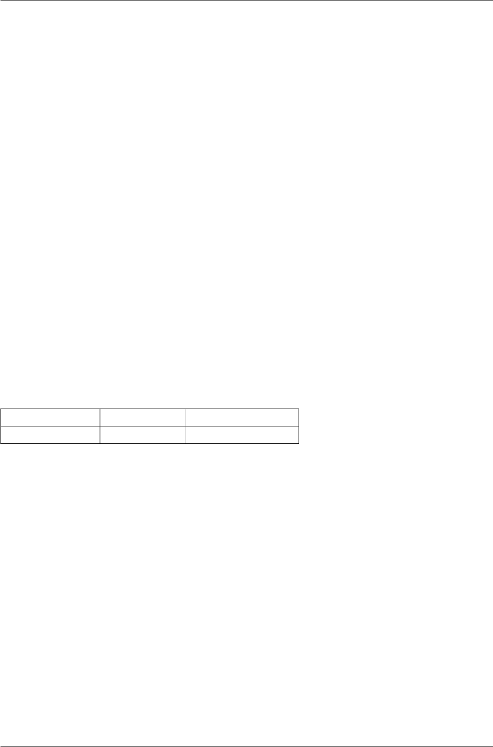
11.9. FCC authorization of transmitters
FCC verification
RAy2-11 was verified for compliance according to CFR 47 part 101 [see §101.139(a)].
FCC comment -
according to §101.141 and considering the low spectral efficiency the following modulations are not
allowed in RAy2-11:
ModulationBandwidth
QPSK2.5 MHz
QPSK3.75 MHz
QPSK5 MHz
QPSK, 16-QAM, 32-QAM10 MHz
QPSK30 MHz
QPSK40 MHz
Except during anomalous signal fading. During anomalous signal fading, licensees may adjust to a
modulation specified in their authorization if such modulation is necessary, to allow the licensees to
maintain communications, even if the modulation does not comply with the capacity and loading require-
ments -101.141 (3).
FCC compliance
RAy2-24 complies with CFR 47 part 15.
FCC IDFCC partCode
SQT-RAY2-2415RAy2-24
RAy2 Microwave Link – © RACOM s.r.o.268
Safety, environment, licensing

11.10. Country of Origin Declaration
Country of Origin Declaration
Producer: RACOM s.r.o.
Address: Mirova 1283, 592 31 Nove Mesto na Morave, Czech Republic
VAT No: CZ46343423
We, the manufacturer, hereby declare that Country of Origin of the RAy microwave links
and its accessories is the Czech Republic, EU.
Nove Mesto na Morave,
Jiri Hruska, CEO
15 of March 2015
www.racom.eu
RACOM s.r.o. • Mirova 1283 • 592 31 Nove Mesto na Morave • Czech Republic
Tel.: +420 565 659 511 • Fax: +420 565 659 512 • E-mail: racom@racom.eu
Part Number Description
RAy2-10 Unit RAy2-10, 2× Gb Eth
RAy2-11 Unit RAy2-11, 2× Gb Eth
RAy2-17 Unit RAy2-17, 2× Gb Eth
RAy2-24 Unit RAy2-24, 2× Gb Eth
ver. 1.1
Fig. 11.5: Country of Origin Declaration
269© RACOM s.r.o. – RAy2 Microwave Link
Safety, environment, licensing
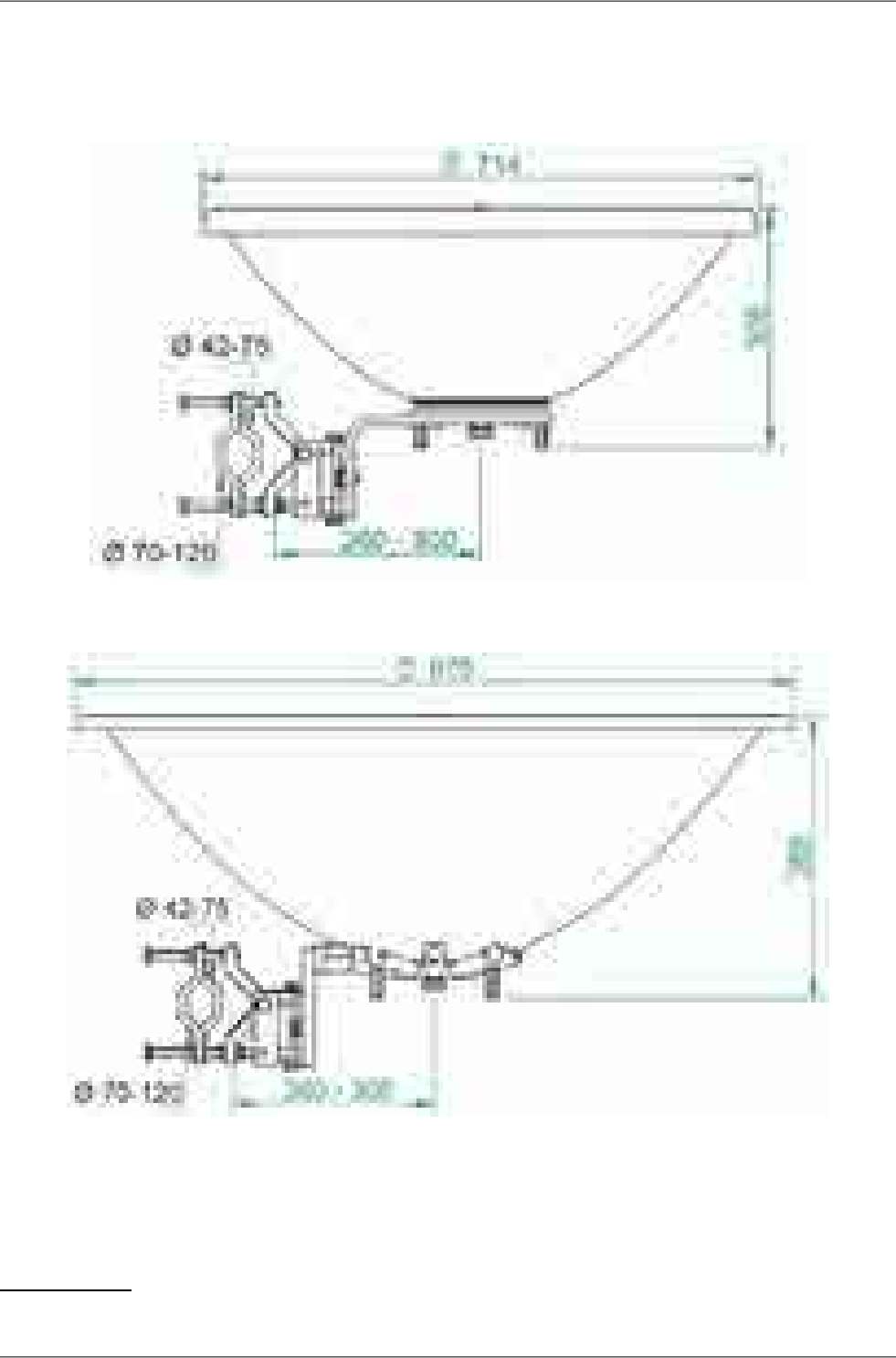
Appendix A. Antenna dimensions
Example antenna's diameter of 68 and 90 cm. More on www.racom.eu1.
Fig. A.1: Jirous antenna 68
Fig. A.2: Jirous antenna 90
1http://www.racom.eu/eng/products/microwave-link.html#download
RAy2 Microwave Link – © RACOM s.r.o.270
Antenna dimensions

Appendix B. Rain zone map
271© RACOM s.r.o. – RAy2 Microwave Link
Rain zone map
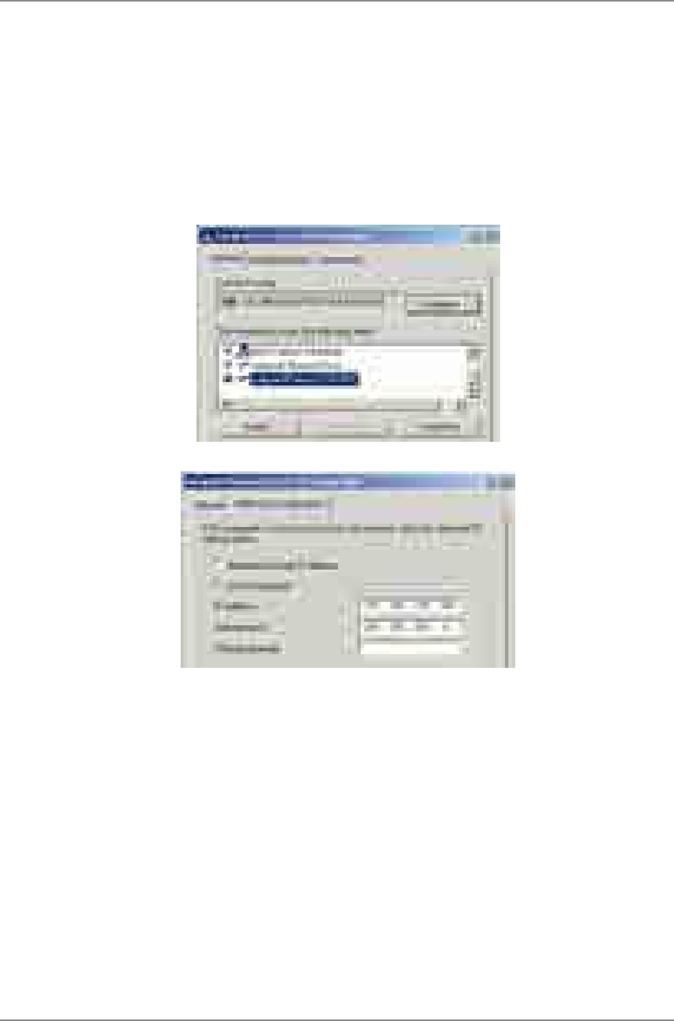
Appendix C. IP address in the PC (Windows XP)
Setting up the IP address in the PC
For configuration of the link a suitable IP address has to be set up in the PC, for example
192.168.169.160
• Open the Start menu, Settings,Network Connections,Local Area Connection
• In the window Local Area Connection select Properties
• Another window opens. Select Internet Protocol (TCP/IP) and click Properties:
• Another window opens. On the General tab select Use the following IP address:
• Enter IP Address IP 192.168.169.160
• Set Subnet mask to 255.255.255.0
• Click OK to acknowledge these settings and close all windows
RAy2 Microwave Link – © RACOM s.r.o.272
IP address in the PC (Windows XP)
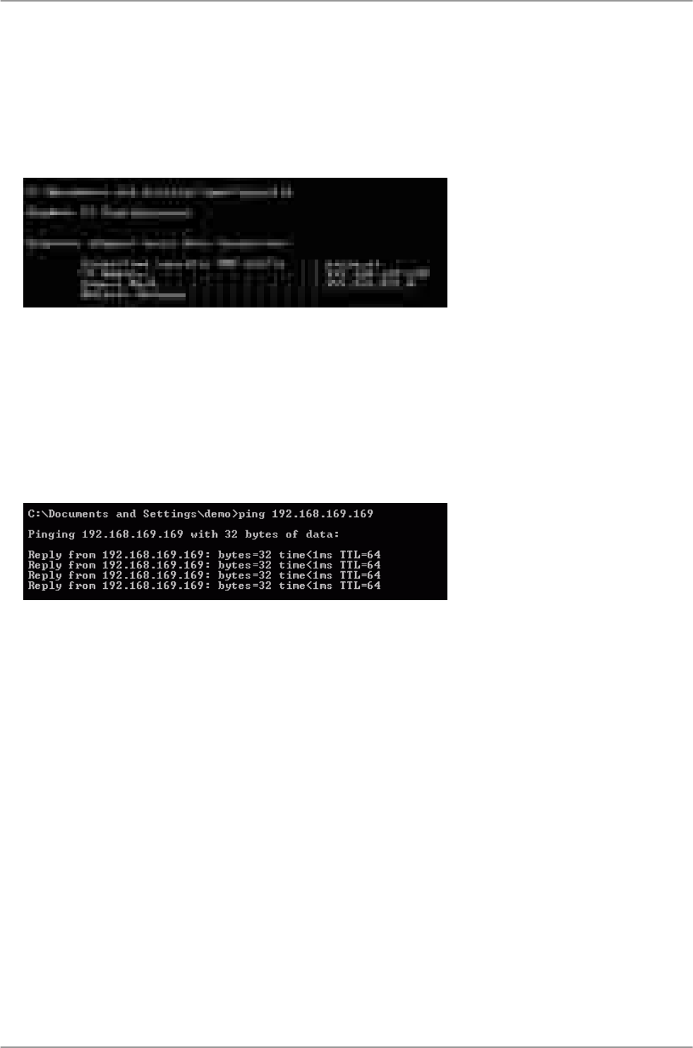
Checking the IP address in the PC
In Windows XP proceed in the following manner:
• Interconnect the configured unit and PC with an Ethernet cable
• Open the Start menu and click Run...
• Enter command cmd
• Enter command ipconfig and read the PC IP address and mask:
Checking the PC - unit connection using Ping
In Windows XP send a ping as follows:
• Check the connection between the PC and the unit via the Ethernet cable.
• In the Start menu click Run...
• Enter command cmd
• Write ping 192.168.1.2 and press OK
• A message appears in a window:
If no communication takes place a message appears with the text "Request timed out".
If communication between the web browser and the unit doesn't take place check the browser settings.
The Work offline item in the File menu must not be crossed out.
273© RACOM s.r.o. – RAy2 Microwave Link
IP address in the PC (Windows XP)
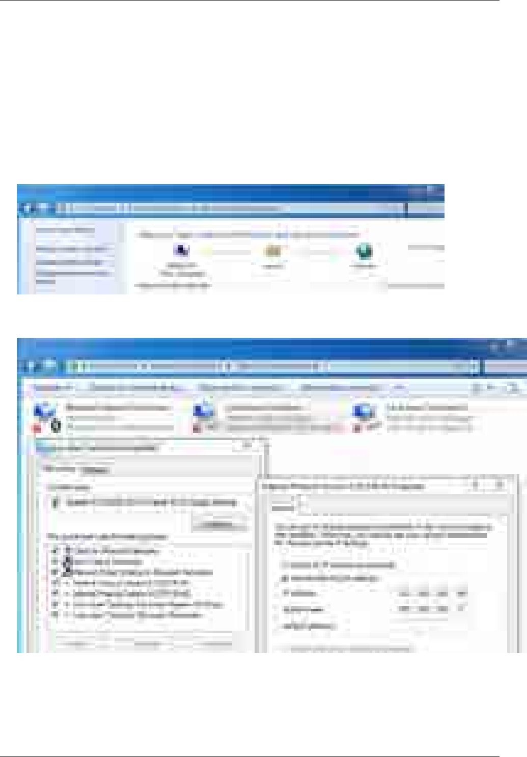
Appendix D. IP address in the PC (Windows 7)
Setting up the IP address in the PC
For configuration of the link a suitable IP address has to be set up in the PC, for example
192.168.169.160
• Open the Start menu, Control Panel
• In new window choose Network and Internet
• Continue View network status and tasks
• In new window choose Change adapter settings:
• In the Network Connections window, right-click on Local area connection and then left-click on
Properties:
• Select Internet Protocol Version 4 (TCP/IPv4) and Properties
• On the General tab select Use the following IP address
○ Enter IP Address 192.168.169.160
○ Set Subnet mask to 255.255.255.0
○ Click OK to acknowledge these settings and close all windows
RAy2 Microwave Link – © RACOM s.r.o.274
IP address in the PC (Windows 7)
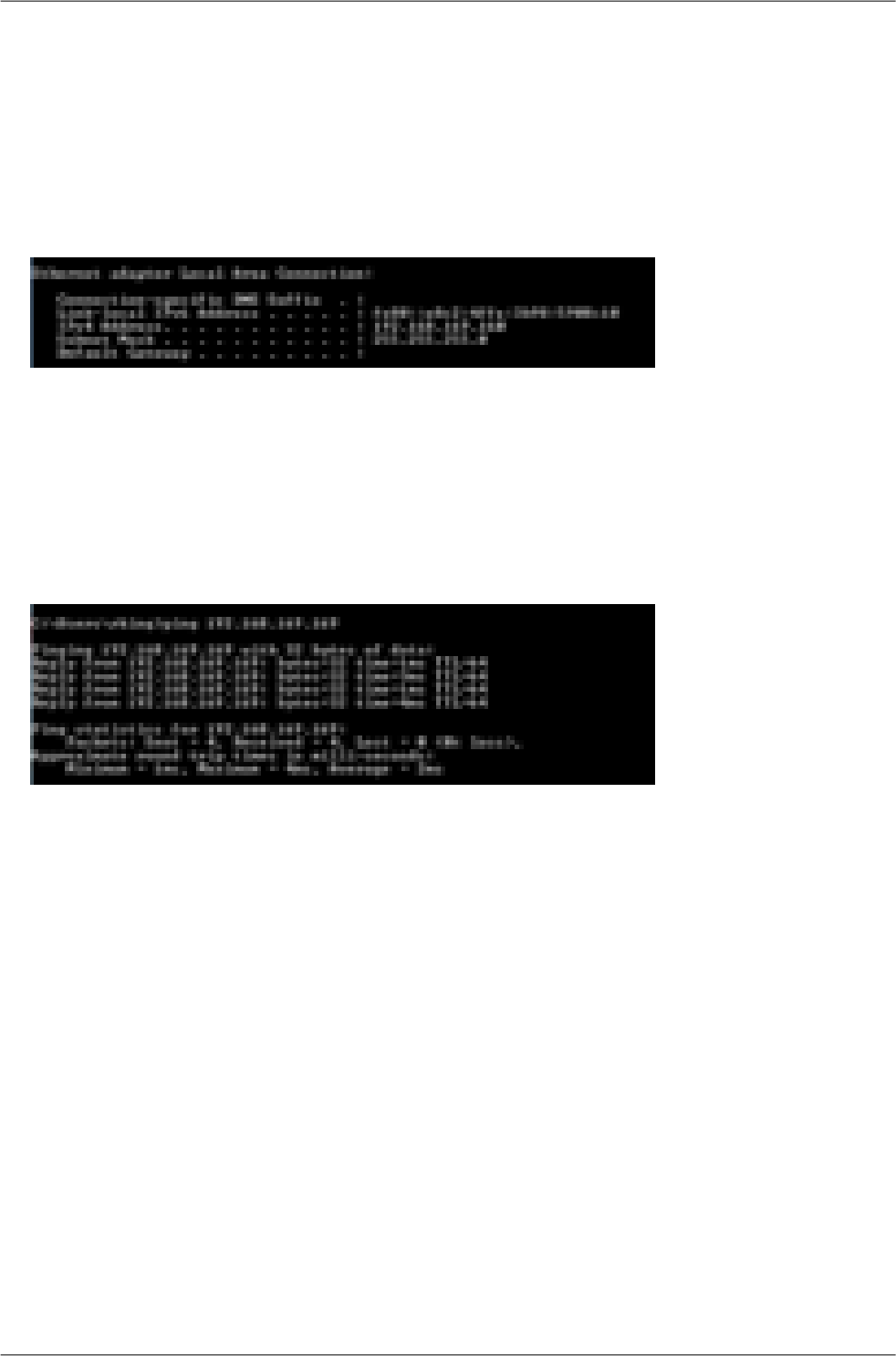
Checking the IP address in the PC
In Windows 7 proceed in the following manner:
• Interconnect the configured unit and PC with an Ethernet cable
•Under the Start menu, type the command cmd in the Search programs and files box
and press Enter.
•Inside the cmd.exe window that opens, enter the command ipconfig at the command prompt
and find the information about IP address and mask among the list of messages returned.
Checking the PC - unit connection using Ping
• Check the connection between the PC and the unit via the Ethernet cable.
•Under the Start menu, type the command cmd in the Search programs and files box
and press Enter.
•Inside the cmd.exe window that opens, type ping 192.168.169.169 at the command prompt
and press Enter.
• Ping times and statistics are returned as shown:
If no communication takes place a message appears with the text Request timed out.
If communication between the web browser and the unit doesn't take place check the browser settings.
E.g. the Work offline item in the File menu must not be crossed out.
275© RACOM s.r.o. – RAy2 Microwave Link
IP address in the PC (Windows 7)
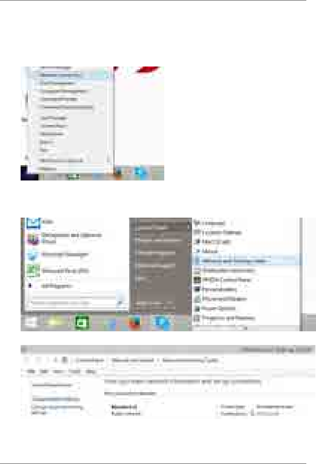
Appendix E. IP address in the PC (Windows 8)
Windows 8 allows you to access the Network Connections page in different ways, for example:
■ Using Start Button
○Start button (left down corner), Right click, choose Network Connections
○ Continue to the Network Connections page.
■ Using Start Button
○Start button, Left click, choose Control Panel and Network and Sharing Center
○ Select Change adapter settings in the Network and Sharing Center
○ Continue to the Network Connections page.
■ From Task Bar
RAy2 Microwave Link – © RACOM s.r.o.276
IP address in the PC (Windows 8)
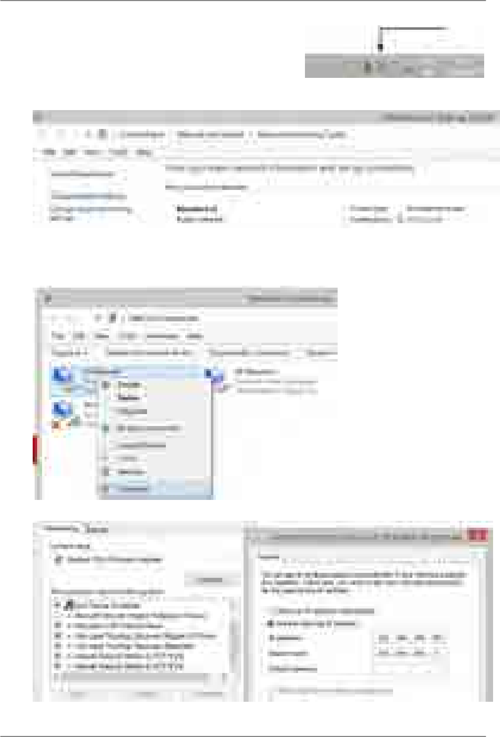
○Click the icon for Internet access
on the task bar in the lower right corner
○ Select Change adapter settings in the Network and Sharing Center
○ Continue to the Network Connections page.
■ On the Network Connections page:
○ Select Properties from Ethernet Network drop down menu
○ Choose Internet Protocol Version 4 (TCP/IPv4), Properties,Use the following IP address
277© RACOM s.r.o. – RAy2 Microwave Link
IP address in the PC (Windows 8)
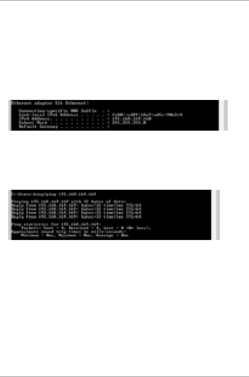
■ Enter IP Address 192.168.169.160
■ Set Subnet mask to 255.255.255.0
■ Click OK to acknowledge these settings and close all windows
Checking the IP address in the PC
In Windows 8 proceed in the following manner:
• Interconnect the configured unit and PC with an Ethernet cable
• Right click on the Start button, type the command cmd and press Enter.
•Inside the cmd.exe window that opens, enter the command ipconfig at the command prompt
and find the information about IP address and mask among the list of messages returned.
Checking the PC - unit connection using Ping
• Check the connection between the PC and the unit via the Ethernet cable.
• Right click on the Start button, type the command cmd and press Enter.
•Inside the cmd.exe window that opens, type ping 192.168.169.169 at the command prompt
and press Enter.
• Ping times and statistics are returned as shown:
If no communication takes place a message appears with the text Request timed out.
If communication between the web browser and the unit doesn't take place check the browser settings.
E.g. the Work offline item in the File menu must not be crossed out.
RAy2 Microwave Link – © RACOM s.r.o.278
IP address in the PC (Windows 8)
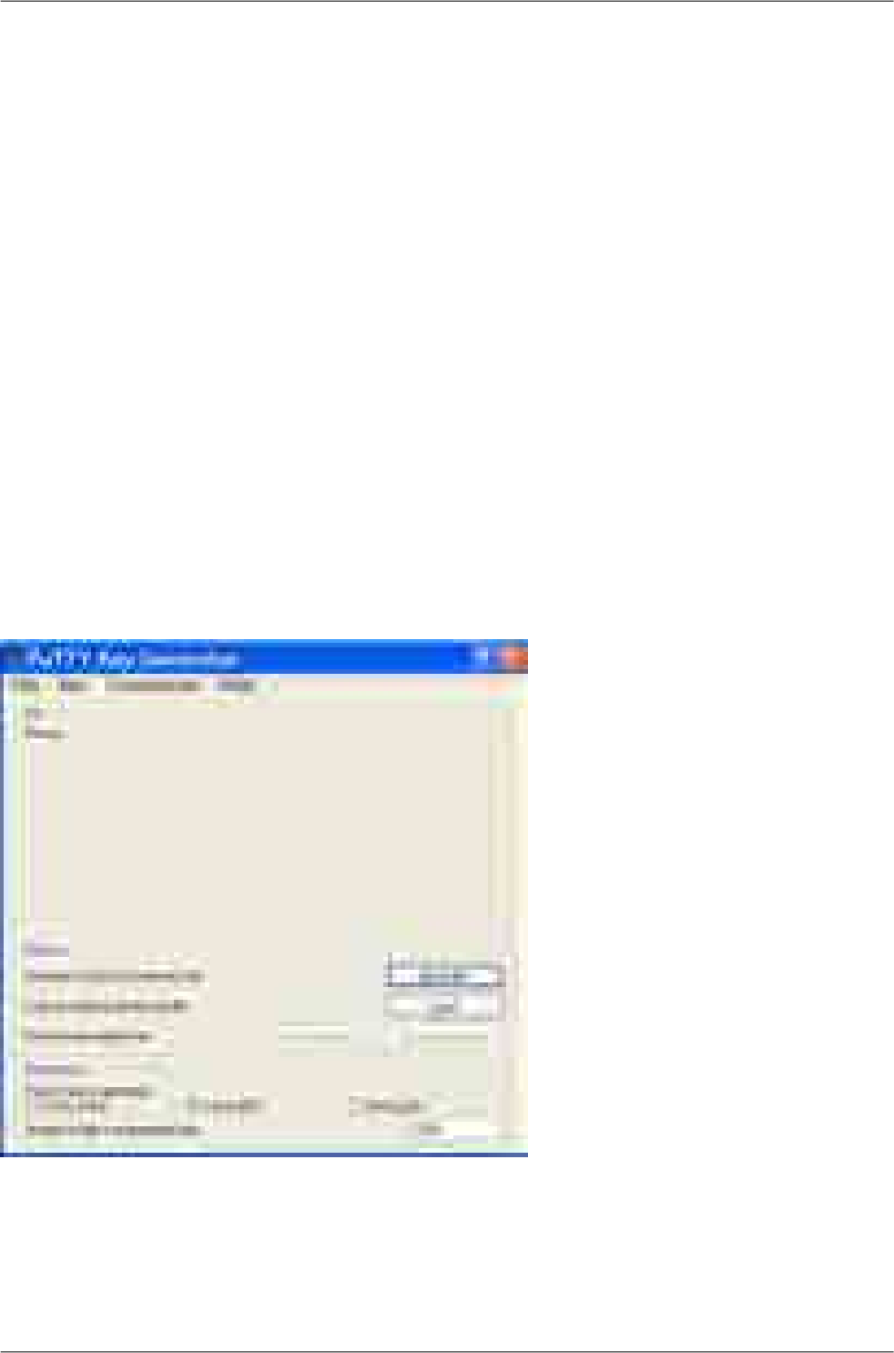
Appendix F. SSH key generation
Linux
Use “ssh-keygen” command.
Windows
Use "PUTTYGEN.EXE" software, which is typically located in the c:\Program Files\putty\ directory and
apply the "Generate" button.
To use CLI (Command Line Interface) access the unit with a PuTTY client. Access is protected by a
key. The key can be in Linux format and it begins:
-----BEGIN DSA PRIVATE KEY-----
.....
or in PuTTY format which begins:
PuTTY-User-Key-File-2: ssh-dss
.....
To convert the Linux format to PuTTY do the following:
In c:\Program Files\putty\ directory run PUTTYGEN.EXE
Click on “Load” and choose the Linux private key.
In the next window type your password into the Key passphrase and Confirm passphrase fields. After
that click Save private key. Choose location and save the key.
279© RACOM s.r.o. – RAy2 Microwave Link
SSH key generation
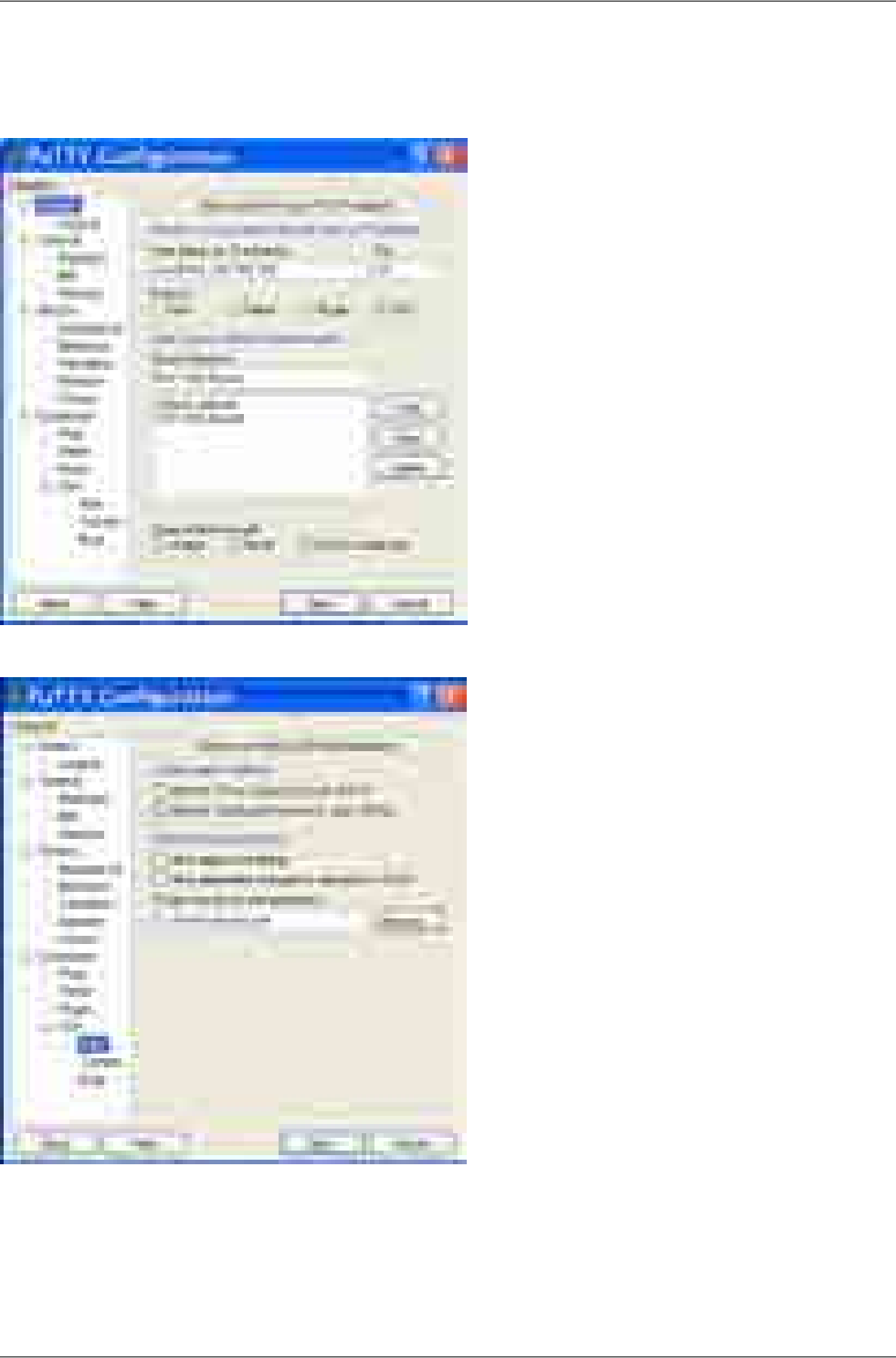
PuTTY access with key
In PuTTY menu fill in the address, e.g. root@192.168.169.169 and the name of the link, e.g. RAy 17
Racom.
Go to Connection / SSH / Auth in the left column and locate the key C:\downloads\ray.ppk
Go back to Session and Save the configuration.
To connect select the name of the connection and click Open. PuTTY asks for password created during
key conversion.
RAy2 Microwave Link – © RACOM s.r.o.280
SSH key generation

Appendix G. Https certificate
When switching from older versions of the firmware the access certificate for https is changed. New
web browser configuration must take place in order to remove the link between the microwave link
management IP address and the previous https certificate.
Mozilla Firefox how-to:
1. https certificate
Remove management IP address from the list: Tools - Options - Advanced - Encryption
- View Certificates – Servers
Another possibility: remove certificate Racom “RAy” or Racom “RACOM's product” from the list:
Tools - Options - Advanced - Encryption - View Certificates – Authorities
2. Upon the new RAy unit connection following message appear: “This Connection is Untrusted”.
3. If you are sure that there is no security risk, choose: “I Understand the Risks”.
4. The next step is “Add Exception...”
5. Finally, you have to “Confirm Security Exception”. If the Apply button is not active, it is necessary
to perform step No. 1/ and restart web browser.
Internet Explorer may give following message “There is a problem with this website's security certificate”.
Choose “Continue to this website (not recommended)”. The address line gives you status information
“Certificate Error”. This inconvenience is caused by impossibility to create security certificate valid for
list of user selected IP addresses.
281© RACOM s.r.o. – RAy2 Microwave Link
Https certificate
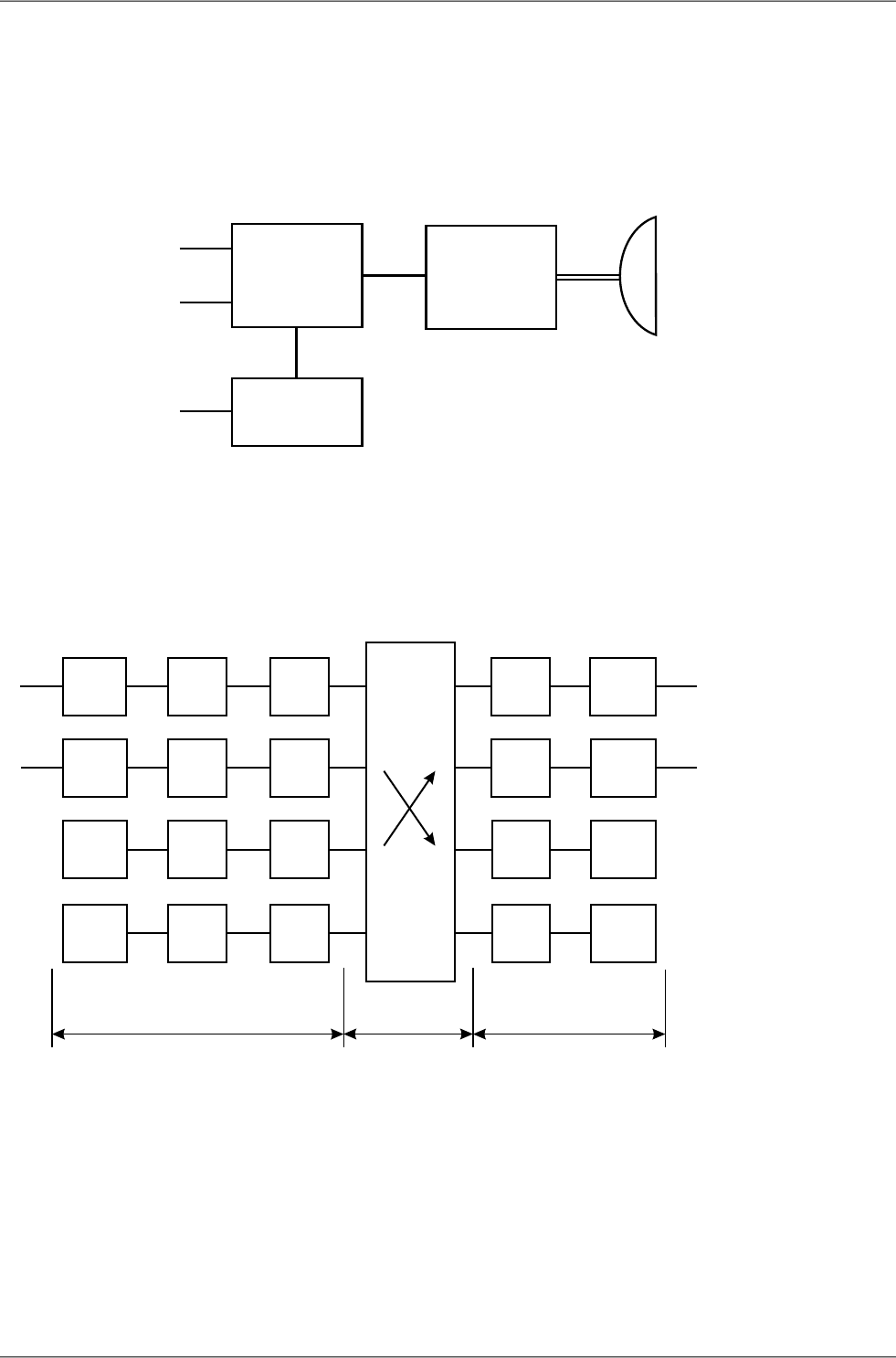
Appendix H. Unit block diagrams
Unit overview
CPU
Eth1
Eth2 Air antenna
SWITCH Radio
Modem
CPU
USB
Fig. H.1: Block diagram of the unit
Switch and connected ports
CPU QoS Egress
Queue
PIRL
Eth1
Eth2
Air
QoS
QoS
QoS
PIRL
PIRL
Egress
Queue
Egress
Queue
Egress
Queue
Eth1
Eth2
Air
SWITCHPHY
PHY
Radio
Modem
Radio
Modem
PHY
PHY
PIRL
CPU CPU CPU
PortPort
Ingress Egress
L2 switching
block
Fig. H.2: Switch and connected ports
Other schemes processing of framework:
Menu PIRL
Menu Advanced
RAy2 Microwave Link – © RACOM s.r.o.282
Unit block diagrams

Index
A
accessories, 28
ACM, 70
adapter
eth, 35
wifi, 35
address
default, 8
IP, 72
IP in RAy, 39
MAC, 68
address IP
PC Windows 7, 274
PC Windows 8, 276
PC Windows XP, 272
alarms, 80
antenna
dimensions, 26, 270
directing, 57
assembly, 42
lubrication, 45, 49
ATPC, 70
ATU, 128
authorization, 168
B
backup, 142
bandwidth, 70
box contens, 10
C
cable bushing, 30
calculation link, 12
CLI, 159, 165
configuration, 62
link, 40
connectors
location, 22
mounting, 50
constellation diagram, 151
copyright, 7
D
declaration of conformity, 264
declaration of origin, 269
default, 8, 37
settings, 142
diagnostics
constellation diagram, 151
graphs, 153
logs, 157
ping, 158
RSS indication, 57, 150
spectrum, 152
diagram
block, 282
PIRL, 99
dimensions, 26
directing
calculation, 12, 59
indication, 57
lobes, 58
screws, 48
dump, 90
E
egress, 86
queue, 108
environment, 260
eth adapter, 35
F
factory settings, 142
FCC authorization, 268
feature keys, 40
fibre cable, 33
firmware, 146
FOD unit
assembly, 45
frame type, 103
frequency tables, 148
frequency TX, 176
Fresnel zone, 17
function test
after installation, 61
before installation, 40
G
graphs, 153
grounding, 35, 52
H
help, 162
https access, 37
I
ingress, 86, 99
installation, 22
polarization, 21, 44, 66
283© RACOM s.r.o. – RAy2 Microwave Link

K
keys, 145
feature, 40
ssh access, 280
ssh conversion, 279
ssh generation, 279
L
leaky bucket, 101
LED, 22, 25
licensing, 260
link
configuration, 40
length, 18
microwave, 11
LLDP protocol, 72
logs, 157
M
mapping
802.1p, 111
DSCP, 113
microwave link, 11
N
name plate, 26
O
ordering codes, 27
P
parameters
setup, 61
table, 172
ping, 158
PIRL, 99
polarization
cross, 44
indication, 66
mounting, 42
policy, 136
port
parameters, 92
trunking, 140
power supply, 23
priority, 103
product, 21
programs, 158
Q
QoS, 83
R
rain zone, 13, 271
rcinfo, 148
restart, 149
rollback, 63, 166
RSS indication, 57
RSS indicator, 150
RSTP, 91, 138
S
safety, 260
distance, 260
scheduling mode, 108
service access, 37, 72
setup parameters, 61
SFP module, 33
spectrum analyzer, 152
SSH access, 165
start, 8, 36
start up, 57
statistics
radio link, 68
RMON, 85
status
bar, 63
LED, 25
menu, 65
STU, 123
T
tables
duplex, 177, 188, 205, 216, 233
frequencies, 176, 181
power, 177, 188, 205, 216, 233
radio parameters, 178
range, 177, 188, 205, 216, 233
RAy2-10, 177
RAy2-11 A,B, 188
RAy2-11 C,D, 204
RAy2-17, 205
RAy2-18, 216
RAy2-24, 233
speeds, 174
technical parameters, 172
time, 69
troubleshooting, 170
trunk, 140
RAy2 Microwave Link – © RACOM s.r.o.284
Index


286

Appendix I. Revision History
287© RACOM s.r.o. – RAy2 Microwave Link
Revision History

2014-05-28Revision 1.0
First issue
2014-06-04Revision 1.1
Name plate changes
2014-07-15Revision 1.2
RAy2-11 C,D user speed and CS correction
2014-07-25Revision 1.3
Accessory supplemented
2014-08-12Revision 1.4
RAy2-11 A,B frequency range corrected
2014-09-01Revision 1.5
Several channels added to RAY2-11 A,B
H/L switching warning
ETH cable grounding
Overview diagram of the unit
IP address setting in Windows 7 and Windows 8 PC
2014-09-10Revision 1.6
Menu description updated for fw 1.3.3.0.
2014-09-12Revision 1.7
Changed the Upper channels labeling at RAy2-17, RAy2-24
Changed the Upper channels frequency for 56 MHz bandwidth at RAy2-17, RAy2-24
2014-11-24Revision 1.8
Added the Switch settings - Advanced menu description
2015-03-06Revision 1.9
Quick Start Guide - new description
Chapter 1 - the technical parameters table moved to Chapter 10
Directing antennas - the new explanation
2015-03-25Revision 1.10
Configuration - updated
Declaration of Conformity - updated
2015-04-21Revision 1.11
USB accessories - updated
Alarm Acknowledge - updated
50 MHz channel on 17 and 24 GHz
RAy2 Microwave Link – © RACOM s.r.o.288
Revision History

2015-06-02Revision 1.12
Updated for fw 2.1.7.0.
Changes in the super user mode
Order code description
RAy2-10 radio parameters updated
Accessories updated
2015-12-01Revision 1.13
Updated for fw 2.1.13.0.
Diagram PIRL improved
Diagram Advanced added
2015-12-30Revision 1.14
RAy2-18 channels added
RAy2-24 FCC channels added
289© RACOM s.r.o. – RAy2 Microwave Link
Revision History