RadarFind M22011 INDOOR EQUIPMENT LOCATION SYSTEM User Manual Installation Manual
RadarFind Corporation INDOOR EQUIPMENT LOCATION SYSTEM Installation Manual
UserManual.wiki
>
RadarFind
>
M22011 User Manual
Installation Manual
Navigation menu
Upload a User Manual
Namespaces
Wiki Guide
HTML
PDF
Info
Views
User Manual
Discussion / Help
Navigation
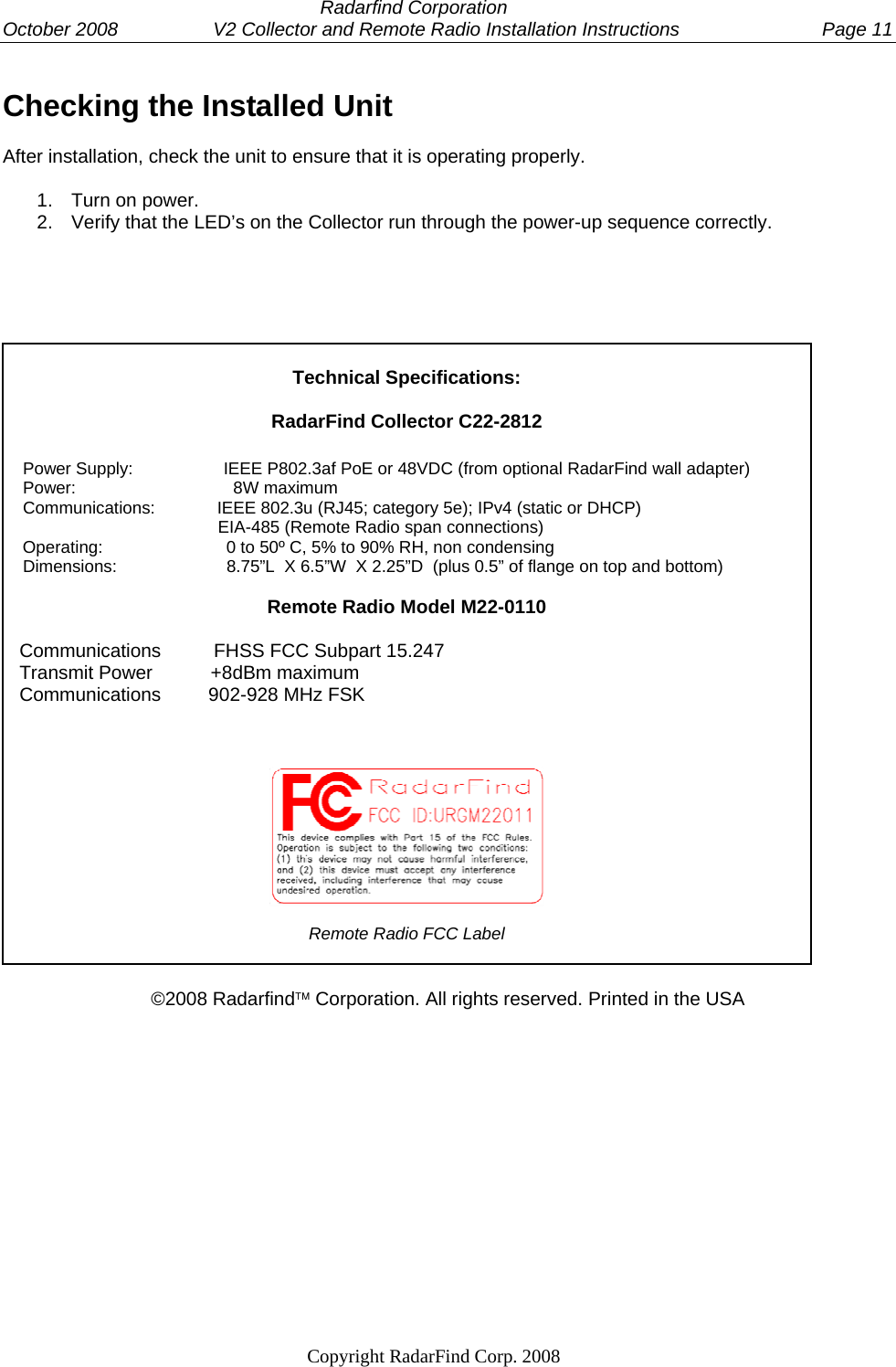
![Radarfind Corporation October 2008 V2 Collector and Remote Radio Installation Instructions Page 2 Copyright RadarFind Corp. 2008 DANGER: • Risk of electric shock. Disconnect all supplies before working on any circuit. • It is important to follow all instructions shipped with this product. Failure to follow all safety precautions and instructions may result in property damage, serious injury, or death to you or others. Cautions: • Electric installation should conform to national, state, and local electrical codes. • Gauge of electric supply wires should be of appropriate section, function of line current, as per local electrical code. • Read all instructions before installing or operating this equipment Remote Radio Model M22-0110 Fcc ID: URGM22011 [15.19] This device complies with Part 15 of the FCC Rules. Operation is subject to the following two conditions: (1) this device may not cause harmful interference, and (2) this device must accept any interference received, including interference that may cause undesired operation. [15.21] Information to user: Changes or modifications not expressly approved by the RadarFind Corporation could void the user's authority to operate the equipment [15.105] NOTE: This equipment has been tested and found to comply with the limits for a Class A digital device, pursuant to Part 15 of the FCC Rules. These limits are designed to provide reasonable protection against harmful interference when the equipment is operated in a commercial environment. This equipment generates, uses, and can radiate radio frequency energy and, if not installed and used in accordance with the instruction manual, may cause harmful interference to radio communications. Operation of this equipment in a residential area is likely to cause harmful interference in which case the user will be required to correct the interference at his own expense. [15.203] This equipment has replaceable antennas with standard SMA type connectors. The RadarFind system must be professionally installed and maintained. Replacement of an antenna with one other than supplied by RadarFind will violate FCC part 15.203 rules, and my cause system malfunctions. [15.247] This equipment operates under Section 15.247 of the Title 47 FCC Rules. Equipment Assessment](https://usermanual.wiki/RadarFind/M22011/User-Guide-1074808-Page-2.png)