RadarFind M22011 INDOOR EQUIPMENT LOCATION SYSTEM User Manual Installation Manual
RadarFind Corporation INDOOR EQUIPMENT LOCATION SYSTEM Installation Manual
Installation Manual
Radarfind Corporation
October 2008 V2 Collector and Remote Radio Installation Instructions Page 1
Copyright RadarFind Corp. 2008
V2 Collector and Remote Radio
Models C22-2812 & M22-0110
Installation Instructions
Radarfind™ Corporation
877-Radarfind (723-2734)
www.radarfind.com
Radarfind Corporation
October 2008 V2 Collector and Remote Radio Installation Instructions Page 2
Copyright RadarFind Corp. 2008
DANGER:
• Risk of electric shock. Disconnect all supplies before working on any
circuit.
• It is important to follow all instructions shipped with this product.
Failure to follow all safety precautions and instructions may result in
property damage, serious injury, or death to you or others.
Cautions:
• Electric installation should conform to national, state, and local electrical
codes.
• Gauge of electric supply wires should be of appropriate section, function of
line current, as per local electrical code.
• Read all instructions before installing or operating this equipment
Remote Radio
Model
M22-0110
Fcc ID:
URGM22011
[15.19] This device complies with Part 15 of the FCC Rules.
Operation is subject to the following two
conditions: (1) this device may not cause harmful interference,
and (2) this device must accept any interference received,
including interference that may cause undesired
operation.
[15.21] Information to user: Changes or modifications not
expressly approved by the RadarFind Corporation could void the
user's authority to operate the equipment
[15.105] NOTE: This equipment has been tested and found to
comply with the limits for a Class A digital device, pursuant to
Part 15 of the FCC Rules. These limits are designed to provide
reasonable protection against harmful interference when the
equipment is operated in a commercial environment.
This equipment generates, uses, and can radiate radio frequency
energy and, if not installed and used in accordance with the
instruction manual, may cause harmful interference to radio
communications.
Operation of this equipment in a residential area is likely to
cause harmful interference in which case the user will be
required to correct the interference at his own expense.
[15.203] This equipment has replaceable antennas with standard
SMA type connectors. The RadarFind system must be professionally
installed and maintained. Replacement of an antenna with one
other than supplied by RadarFind will violate FCC part 15.203
rules, and my cause system malfunctions.
[15.247] This equipment operates under Section 15.247 of the
Title 47 FCC Rules.
Equipment Assessment

Radarfind Corporation
October 2008 V2 Collector and Remote Radio Installation Instructions Page 3
Copyright RadarFind Corp. 2008
Caution: If the equipment is damaged, do not attempt to install or operate it.
1. When the equipment arrives, unpack the unit(s).
2. Check for damage that may have occurred in transit.
3. If contents are damages contact the carrier immediately to file a claim stating the extent of the
damage.
General Safety Information
• Wear safety goggles when working under conditions that might be hazardous to your eyes.
• Keep tools where you and others will not fall over them.
• Keep the installation area clear during the installation.
• Do not wear loose clothing that could become caught in the equipment.
Electrical Safety Information
• Before working on electrical equipment, remove jewelry (necklaces, rings, watches, and so on).
• Refer to the site’s safety precautions for details about site-specific hazards.
• Refer to the collector’s name plate for information on voltage and current.
Radarfind Corporation
October 2008 V2 Collector and Remote Radio Installation Instructions Page 4
Copyright RadarFind Corp. 2008
Remote Radio wiring and Installation
RadarFind Remote Radios are connected to their Collectors with standard Ethernet Cat5e cabling. The
power and signaling used on the cables between the Collectors and the Remote Radios is not Ethernet,
although the wiring and connector pattern is the same.
Note: Never connect a Remote Radio or the Remote Radio connections on a Collector to a
standard Ethernet device or switch.
A Collector may have from 2 to 4 Remote Radios attached. Each Remote Radio location is uniquely
numbered and indicated on the facility plans provided to the installer. Each wiring run between a
Collector and a Remote Radio is identified by a unique ID which are to be clearly marked at both ends of
the cable runs to match the installation plans. (e.g. A cable run from Collector 3WE1 to Remote Radio
3WE1A) Remote Radios must be wired to the specific Collectors as indicated on the plans.
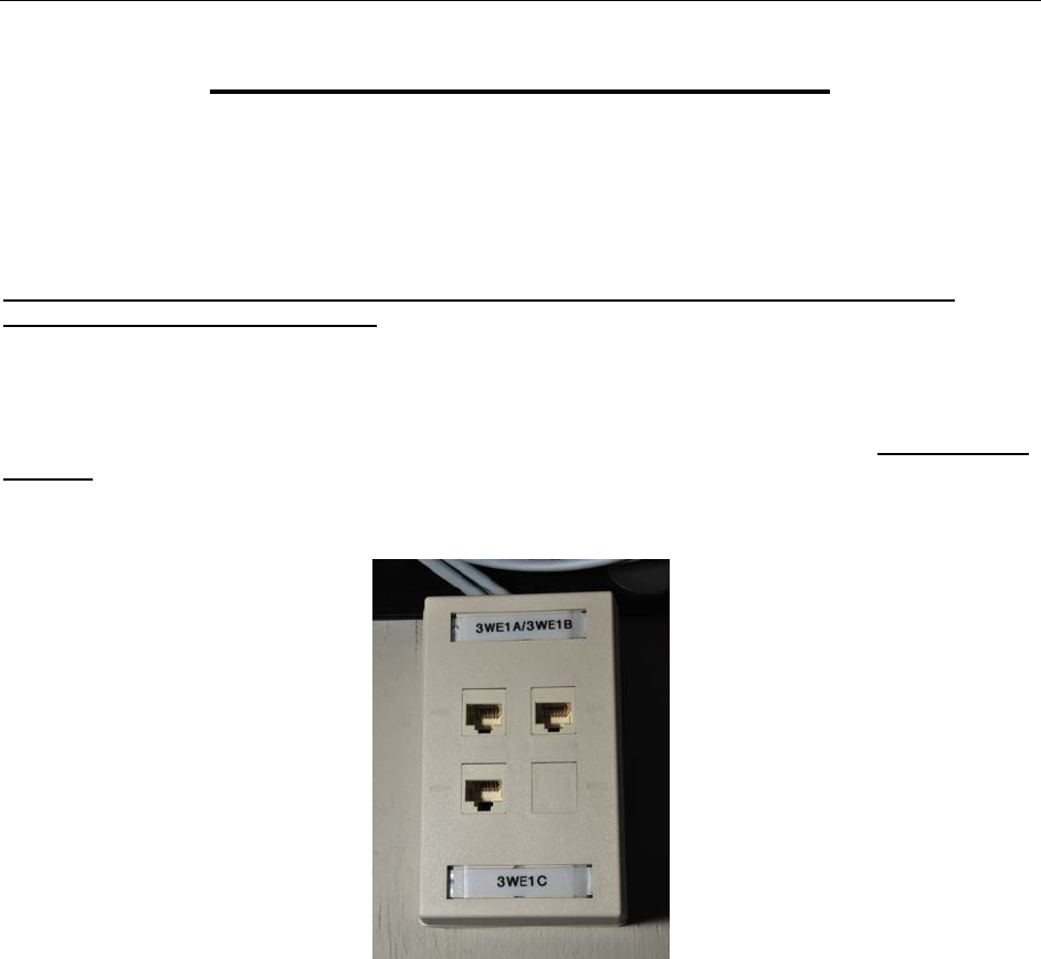
Fig 1 – Standard termination box for Remote Radio cabling at Collector location
Note: If some extraordinary circumstance prevents wiring from being installed as shown on the
plans contact RadarFind for possible alternate solutions.
At the Collector end punch cable runs into a patch box or patch panel and mark with the Remote Radio
ID.
At the Remote Radio end label the cable with the Remote Radio ID and either 1-terminate the cable in an
RJ45 connector or 2-punch down to a surface mounted box with a jumper. The final cable that connects
to the Remote Radio should be white to match the case.
Leave 15’ of coiled extra cable, or jumper, at the Remote Radio end to allow the device to be moved if
required to optimize performance.
Radarfind Corporation
October 2008 V2 Collector and Remote Radio Installation Instructions Page 5
Copyright RadarFind Corp. 2008
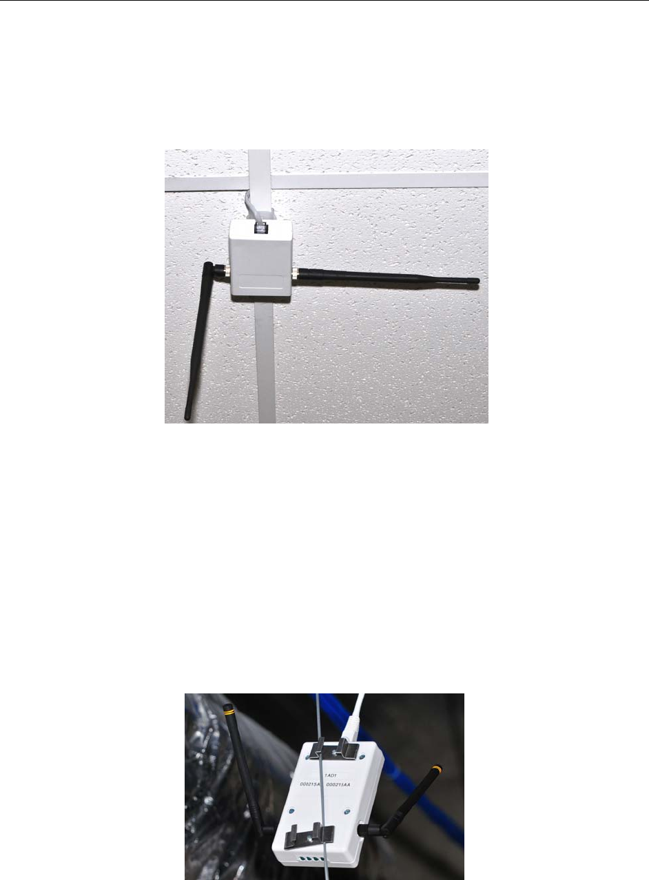
Mounting Remote Radios below the ceiling grid.
Mount the Remote Radio under the ceiling tile grid using the clips provided on the back of the case. Dress
wire neatly, and position one antenna horizontally – facing across the hall - and the other vertically –
facing down.
Fig 2 – Standard mounting for Remote Radio
Note: Any Remote Radio may be used at any location.
Mounting Remote Radios above the ceiling grid.
RadarFind Remote Radios should be mounted under the ceiling grid for best performance. If facility
regulations require that the Remote Radios be mounted above the ceiling grid they should be placed in
such a way that the antennas are well clear of nearby metal objects. A special bracket is available which
attaches to the ceiling grid suspension wire.
Fig 3 – Special mounting for Remote Radio on ceiling suspension wires
Radarfind Corporation
October 2008 V2 Collector and Remote Radio Installation Instructions Page 6
Copyright RadarFind Corp. 2008
Collector Installation
Preparing for Collector Installation
Site Selection Criteria
The selection of the mounting location for the Collector and routing of wiring must be accomplished under
the direction of the facilities engineer and the safety engineer responsible for the proposed building or
location.
The Collector installation location must be indoors and protected from all weather and water. The
mounting surface must be 3/4" plywood (or equivalent) for secure and safe attachment. It is
recommended that the location be in a secured area such as a locked electrical or IT utility closet.
Equipment Connections
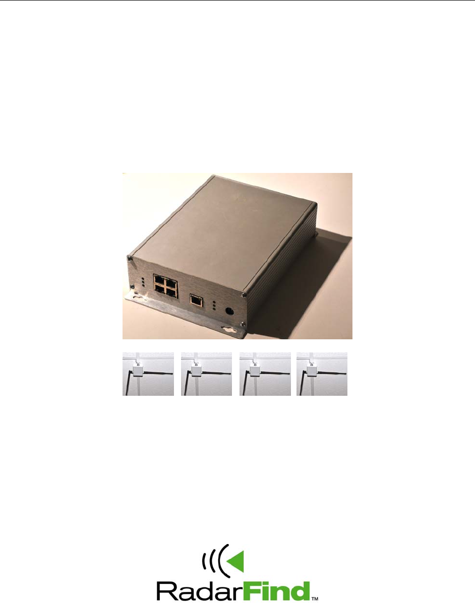
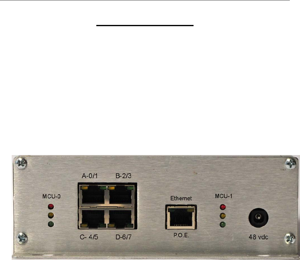
Fig 4 – Collector C22-2812 Front panel
MCU-0 – Microprocessor 0 indicators A-0/1 – Remote Radio A connection
MCU-1 – Microprocessor 1 indicators B-2/3 – Remote Radio B connection
Ethernet – Network connection C-4/5 – Remote Radio C connection
48 vdc – Auxiliary power supply D-6/7 – Remote Radio D connection
Radarfind Corporation
October 2008 V2 Collector and Remote Radio Installation Instructions Page 7
Copyright RadarFind Corp. 2008
Typical Collector Installation
Each RadarFind Collector is labeled and the accompanying installation documentation designates where
each specific Collector is to be placed.
Note: Collectors MUST be placed in the designated locations according to the installation
documentation and plugged into the correct Ethernet and Remote Radio connections.
Installing the Collector
Select a location where the Collector can be easily accessed and the front end with the connectors and
LEDs can be accessed and viewed after installation. For installations where a single Collector is installed
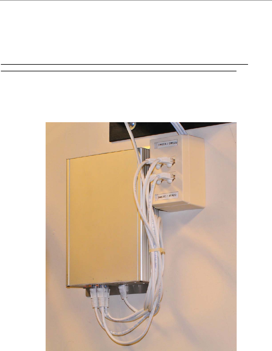
select a location adjacent to the Remote Radio terminal block
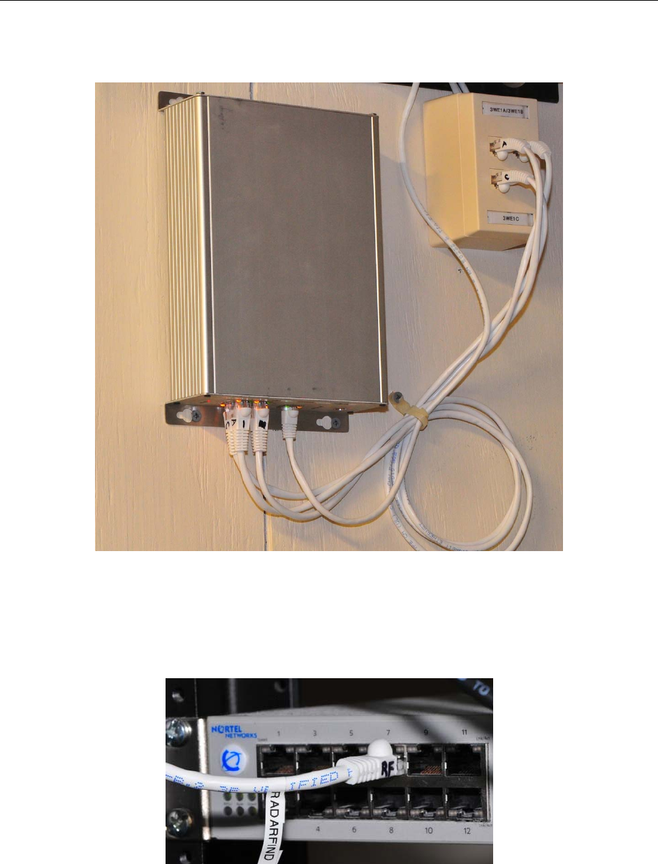
Fig 5 – Finished Collector installation with Remote Radio terminal block.
Radarfind Corporation
October 2008 V2 Collector and Remote Radio Installation Instructions Page 8
Copyright RadarFind Corp. 2008
Installation Procedure
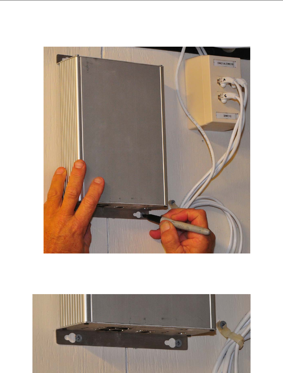
Hold Collector level against wall in desired location and mark the right-most slot of all four mounting
holes.
Figure 6: Marking locations for Collector mounting screws
Set Collector aside and insert four mounting screws into marked holes with about ¼” inch exposed.
Figure 7: Collector on mounting screws after tightening.
Position the Collector in place on the four screw heads, slide Collector to left and tighten screws
Radarfind Corporation
October 2008 V2 Collector and Remote Radio Installation Instructions Page 9
Copyright RadarFind Corp. 2008
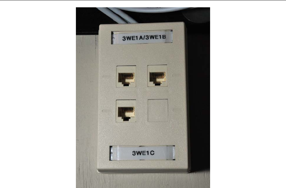
Figure 8: Remote Radio connector block.
Remote Radio punch-down or termination blocks panels will be marked with the ID of each Remote Radio
for the Collector.
The Remote Radio ID # ends in A,B,C, or D, which corresponds with the jack ID on the Collector. Each
Collector may have 2, 3, or 4 Remote Radios.
Mark 4 jumper cables on both ends with their letter designation A/B/C/D and cable each Remote Radio
jack to the matching jack on the Collector A-A, B-B, etc.
Radarfind Corporation
October 2008 V2 Collector and Remote Radio Installation Instructions Page 10
Copyright RadarFind Corp. 2008
Figure 9: Remote Radio jumpers marked and connected to connector block.
Clearly mark and connect an Ethernet jumper from the Collector to the correct P.O.E. enabled port on the
Ethernet switch. If no P.O.E. port is available an injector may be used, or an external power supply is
available from RadarFind.
Figure 10: Collector Ethernet jumper clearly marked at switch end.

Radarfind Corporation
October 2008 V2 Collector and Remote Radio Installation Instructions Page 11
Copyright RadarFind Corp. 2008
Checking the Installed Unit
After installation, check the unit to ensure that it is operating properly.
1. Turn on power.
2. Verify that the LED’s on the Collector run through the power-up sequence correctly.
Technical Specifications:
RadarFind Collector C22-2812
Power Supply: IEEE P802.3af PoE or 48VDC (from optional RadarFind wall adapter)
Power: 8W maximum
Communications: IEEE 802.3u (RJ45; category 5e); IPv4 (static or DHCP)
EIA-485 (Remote Radio span connections)
Operating: 0 to 50º C, 5% to 90% RH, non condensing
Dimensions: 8.75”L X 6.5”W X 2.25”D (plus 0.5” of flange on top and bottom)
Remote Radio Model M22-0110
Communications FHSS FCC Subpart 15.247
Transmit Power +8dBm maximum
Communications 902-928 MHz FSK
Remote Radio FCC Label
©2008 Radarfind™ Corporation. All rights reserved. Printed in the USA