RadarFind R224012 INDOOR EQUIPMENT LOCATION SYSTEM User Manual
RadarFind Corporation INDOOR EQUIPMENT LOCATION SYSTEM Users Manual
UserManual.wiki
>
RadarFind
>
R224012 User Manual
Users Manual
Navigation menu
Upload a User Manual
Namespaces
Wiki Guide
HTML
PDF
Info
Views
User Manual
Discussion / Help
Navigation
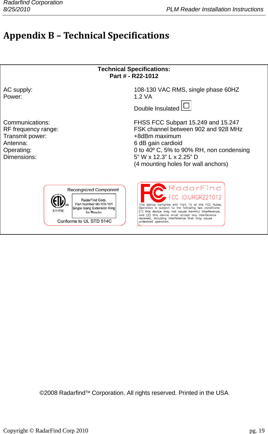
![Radarfind Corporation 8/25/2010 PLM Reader Installation Instructions Copyright © RadarFind Corp 2010 pg. 2 DANGER: • Risk of electric shock. Disconnect all supplies before working on any circuit. • It is important to follow all instructions shipped with this product. Failure to follow all safety precautions and instructions may result in property damage, serious injury, or death to you or others. Cautions: • Risk of malfunction. Use only copper wires of size 12AWG (or larger) suitable for 105°C (221°F). • Installation should conform to national, state, and local electrical codes. • Gauge of electric supply wires should be of appropriate section, function of line current, as per NEC electrical code. • This device must be installed directly into the electrical system. • This device must be installed by a trained and licensed electrician who is thoroughly familiar with the National Electrical Code and follows the NEC Guidelines as well as state and local codes. Reader Model R22-1012 Fcc ID: URGR221012 [15.19] This device complies with Part 15 of the FCC Rules. Operation is subject to the following two conditions: (1) this device may not cause harmful interference, and (2) this device must accept any interference received, including interference that may cause undesired operation. [15.21] Information to user: Changes or modifications not expressly approved by the RadarFind Corporation could void the user's authority to operate the equipment [15.105] NOTE: This equipment has been tested and found to comply with the limits for a Class A digital device, pursuant to Part 15 of the FCC Rules. These limits are designed to provide reasonable protection against harmful interference when the equipment is operated in a commercial environment. This equipment generates, uses, and can radiate radio frequency energy and, if not installed and used in accordance with the instruction manual, may cause harmful interference to radio communications. Operation of this equipment in a residential area is likely to cause harmful interference in which case the user will be required to correct the interference at his own expense. [15.247] This equipment operates under Section 15.247 of the Title 47 FCC Rules. [15.249] This equipment operates under Section 15.249 of the Title 47 FCC Rules. This product protected by one or more of the following U.S. Patents: 7372365, 7525432 & 7528716. Other patents pending](https://usermanual.wiki/RadarFind/R224012/User-Guide-1345469-Page-2.png)