RadarFind R224012 INDOOR EQUIPMENT LOCATION SYSTEM User Manual
RadarFind Corporation INDOOR EQUIPMENT LOCATION SYSTEM Users Manual
Users Manual

Copyright © RadarFind Corp 2008
V2 Reader
Installation Instructions
For Reader Models:
R22-1012 with P10-xx10 PlugSert option
R22-4012 with 80-113-1002 external power supply
RadarFind™ Corporation
877-RadarFind (723-2734)
www.radarfind.com

Radarfind Corporation
8/25/2010 PLM Reader Installation Instructions
Copyright © RadarFind Corp 2010 pg. 2
DANGER:
• Risk of electric shock. Disconnect all supplies before working on any
circuit.
• It is important to follow all instructions shipped with this product.
Failure to follow all safety precautions and instructions may result in
property damage, serious injury, or death to you or others.
Cautions:
• Risk of malfunction. Use only copper wires of size 12AWG (or larger)
suitable for 105°C (221°F).
• Installation should conform to national, state, and local electrical codes.
• Gauge of electric supply wires should be of appropriate section, function of
line current, as per NEC electrical code.
• This device must be installed directly into the electrical system.
• This device must be installed by a trained and licensed electrician who is
thoroughly familiar with the National Electrical Code and follows the NEC
Guidelines as well as state and local codes.
Reader Model
R22-1012
Fcc ID:
URGR221012
[15.19] This device complies with Part 15 of the FCC Rules.
Operation is subject to the following two conditions: (1) this
device may not cause harmful interference, and (2) this device
must accept any interference received, including interference
that may cause undesired operation.
[15.21] Information to user: Changes or modifications not
expressly approved by the RadarFind Corporation could void the
user's authority to operate the equipment
[15.105] NOTE: This equipment has been tested and found to
comply with the limits for a Class A digital device, pursuant to
Part 15 of the FCC Rules. These limits are designed to provide
reasonable protection against harmful interference when the
equipment is operated in a commercial environment.
This equipment generates, uses, and can radiate radio frequency
energy and, if not installed and used in accordance with the
instruction manual, may cause harmful interference to radio
communications.
Operation of this equipment in a residential area is likely to
cause harmful interference in which case the user will be
required to correct the interference at his own expense.
[15.247] This equipment operates under Section 15.247 of the
Title 47 FCC Rules.
[15.249] This equipment operates under Section 15.249 of the
Title 47 FCC Rules.
This product protected by one or more of the following U.S.
Patents: 7372365, 7525432 & 7528716. Other patents pending

Radarfind Corporation
8/25/2010 PLM Reader Installation Instructions
Copyright © RadarFind Corp 2010 pg. 3
General Safety Information
• Wear safety goggles when working under conditions that might be hazardous to your
eyes.
• Keep tools where you and others will not fall over them.
• Keep the installation area clear during the installation.
• Do not wear loose clothing that could become caught in the equipment.
Electrical Safety Information
• Before working on electrical equipment, remove jewelry (necklaces, rings, watches, etc).
• Locate the emergency on/off switch closest to the installation site.
• Before installation, turn OFF the power.
• Refer to the site’s safety precautions for details about site-specific hazards.
• Refer to the Reader name plate for information on voltage and current.
Contents
General Installation Instructions ..................................................................................................................... 4
IMPORTANT INFORMATION .................................................................................................................... 4
Preparing for Installation ................................................................................................................................ 5
1 - Installing a RadarFind Plug-in Reader ...................................................................................................... 6
2 - Reversing the PlugSert in a Reader ........................................................................................................... 8
3 - Installing a RadarFind EVN Reader (with external power supply) ......................................................... 11
4 - Hard wiring a Reader .............................................................................................................................. 13
4.1 Removing the PlugSert ........................................................................................................................... 13
4.2 - Hard wired Reader Installation Procedure ........................................................................................... 14
5 - Reader Mounting Accessories ................................................................................................................ 16
Appendix A – Reader Indicator LED ........................................................................................................... 18
Appendix B – Technical Specifications ....................................................................................................... 19

Radarfind Corporation
8/25/2010 PLM Reader Installation Instructions
Copyright © RadarFind Corp 2010 pg. 4
GeneralInstallationInstructions
a- A RadarFind Reader as shipped can only be installed on receptacles
with the ground pin up. If it is necessary to install a Reader 180
degrees off-axis from the existing receptacle the orientation of the
Reader PlugSert may be reversed (See Section 2)
b- If a Reader requires being installed at 90 degrees to the existing
receptacle, must be offset, installed over a double gang plate, or
installed over a GFCI or single outlet receptacle the services of an
electrician is required. (See Section 4)
c- In some locations where the only available power is on a plug-strip,
head-board unit, or behind a metal cabinet or refrigerator the only
option may be to use an EVN Reader, which is powered by an
external supply. Due to the vulnerability of the power supply and
cord this should be reserved as a last option.
IMPORTANTINFORMATION
ALWAYS confirm that the Location ID on the label on top
of the Reader matches the Location ID on the map where
Reader is installed.
If it is necessary to install a Reader in any other location
for any reason RadarFind must be notified ASAP in the
comment section of the Reader worksheet.
Radarfind Corporation
8/25/2010 PLM Reader Installation Instructions
Copyright © RadarFind Corp 2010 pg. 5
PreparingforInstallation
Note: There are a number of options for installing a RadarFind Reader. Read all instructions
before installing or operating this equipment.
Site Selection Criteria
The selection of the mounting location for the reader and the method of connecting it into the
existing electrical system must be accomplished under the direction of the facilities engineer and
the safety engineer responsible for the proposed building or location.
The installation location must be indoors and protected from all weather and water. All provided
mounting fasteners must be used for secure and safe attachment.
Equipment Assessment
Caution: If the equipment is damaged, do not attempt to install or operate it.
1. When the equipment arrives, unpack the unit(s).
2. Check for damage that may have occurred in transit.
3. Contact the carrier immediately to file a claim stating the extent of the damage, and
contact RadarFind customer service for repair or replacement.
4. Review the following checklist to ensure that all necessary materials are available for
installation.
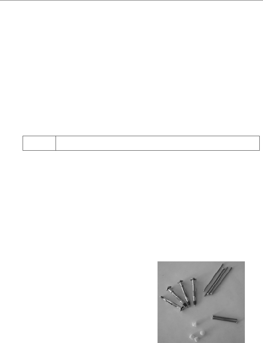
Reader unit
2—3/4” #6 screws – For mounting Reader
to existing electrical box. (Wired Reader
only)
4—hollow wall “Polly” or metal “ZipIt”
anchors
4—3” #6 screws for use with the wall
anchors
4—plastic mounting hole plugs
EVN Readers come with an external power supply attached.
Radarfind Corporation
8/25/2010 PLM Reader Installation Instructions
Copyright © RadarFind Corp 2010 pg. 6
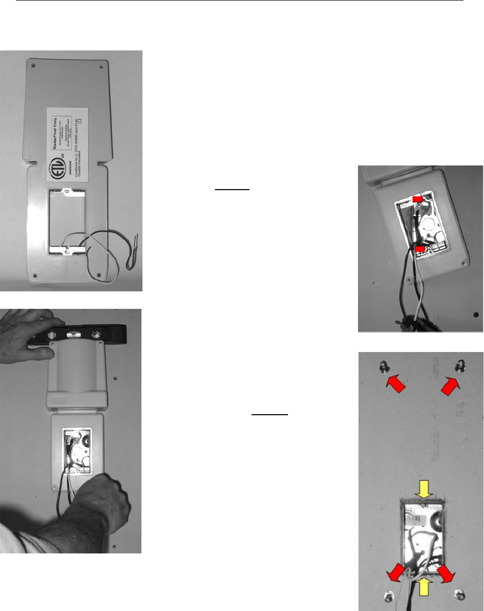
1‐InstallingaRadarFindPlug‐inReader
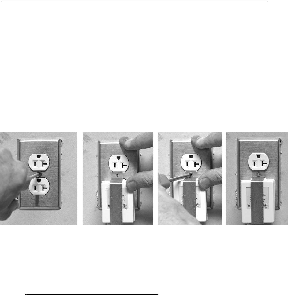
Plug-in Installation Procedure
1. Remove existing receptacle cover plate from wall.
2. Plug Reader into existing receptacle
3. Level Reader and mark wall for four corner mounting
anchors.
4. Remove Reader.
5. Insert included wall anchors at punch marked
locations, tighten until securely compressed into
wall, then remove screws from anchors and discard.
(The heads on the anchor screws are too large to be used in
the Reader)
( If the supplies wall anchors are not suitable for the wall material use a suitable
replacement)
6. Plug Reader into receptacle.
7. Insert and secure 4 corners using the (4) 3” #6
screws, tighten to 12 inch pounds.
8. Tighten Reader receptacle cover plate screw
9. Plug four corner holes with plugs provided.
10. Verify that the Reader has power by observing
the blinking LED.

Radarfind Corporation
8/25/2010 PLM Reader Installation Instructions
Copyright © RadarFind Corp 2010 pg. 7
11. Note on the worksheet the LED blink pattern.
Radarfind Corporation
8/25/2010 PLM Reader Installation Instructions
Copyright © RadarFind Corp 2010 pg. 8
2‐ReversingthePlugSertinaReader
In places where the Reader must be installed on a receptacle in the opposite
orientation the PlugSert in the Reader may be reversed. This is required where the
ground pin of the wall receptacle is down, or insufficient clearance exists to mount the
Reader with the Antenna up.
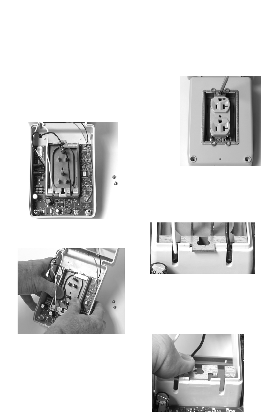
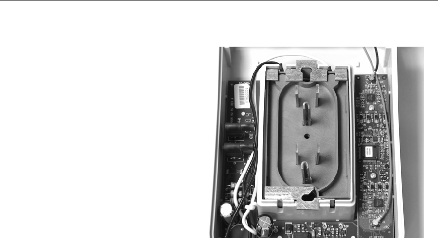
1. Remove the two short receptacle mounting
screws.
2. Carefully free the PlugSert wires and
dress them up and out of the wire
slots.
3. Gently push the PlugSert out of the
Reader from the back, being careful
not to damage the wires attached to
the PlugSert.
4. Let the PlugSert rest on a table and
remove the metal mounting bracket by
pressing the locking tabs toward each
other and sliding the bracket out of the
front of the Reader.
Radarfind Corporation
8/25/2010 PLM Reader Installation Instructions
Copyright © RadarFind Corp 2010 pg. 9
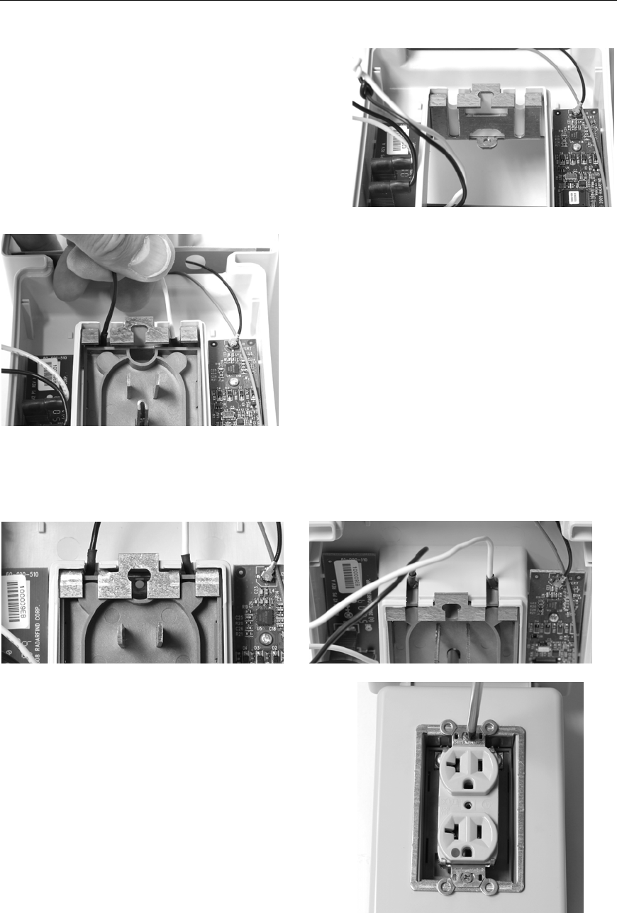
5. Invert the mounting bracket and re-
insert into the Reader so the wire slots
in the bracket align with the top wire
slots in the Reader housing.
6. While holding the wires to keep them
aligned in the wire slots gently replace
the PlugSert into the Reader.
7. Check to make sure the PlugSert wires are not pinched between the bracket and
the PlugSert boby. The shrink tubing on the wire ends should protrude equally
from both slots.
8. Replace the short receptacle mounting
screws.
Radarfind Corporation
8/25/2010 PLM Reader Installation Instructions
Copyright © RadarFind Corp 2010 pg. 10
9. Dress the PlugSert wires
back neatly into the Reader
housing and replace the
Reader back.
10. Proceed with Reader
installation as outlined in
Section 1.
Radarfind Corporation
8/25/2010 PLM Reader Installation Instructions
Copyright © RadarFind Corp 2010 pg. 11
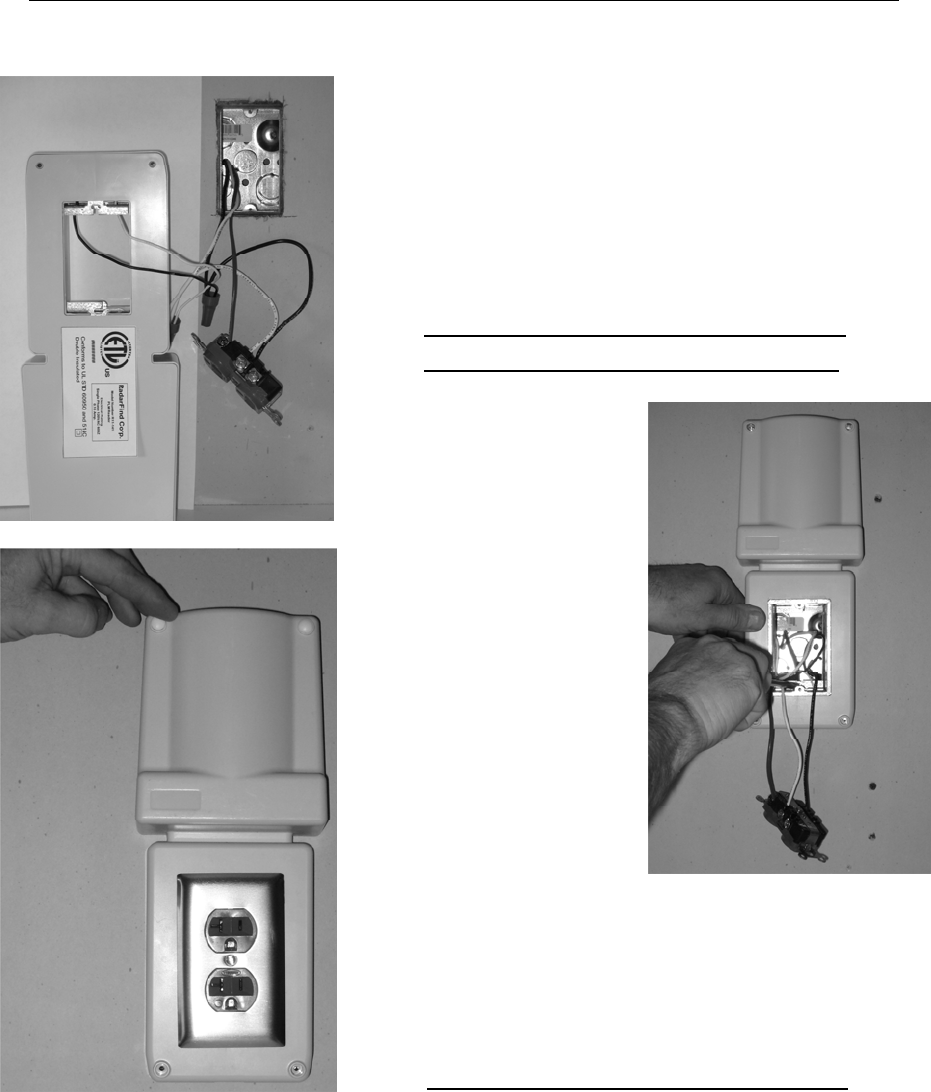
3‐InstallingaRadarFindEVNReader(withexternalpowersupply)
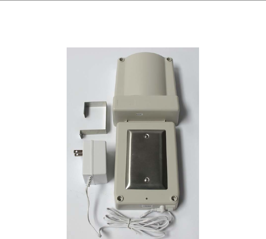
RadarFind EVN Reader Kit
Note: The preferred method of installation is always to permanently mount
the Reader on a receptacle, using the methods described in Section 1/2 or
Section 4)
Occasionally circumstances prevent such installations and require the use
of an EVN type Reader which uses an external power supply, e.g where the
only power available is on a headboard or plug-strip or the receptacle is
hidden behind a large metal cabinet.
Radarfind Corporation
8/25/2010 PLM Reader Installation Instructions
Copyright © RadarFind Corp 2010 pg. 12
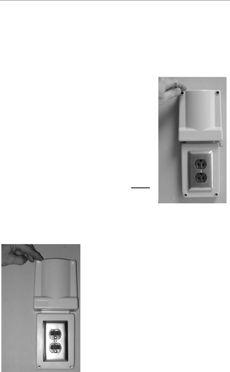
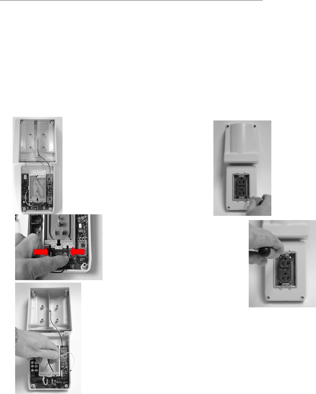
EVN Reader Installation Procedure
1 - Select a good location close to the available power to keep the cord distance to a
minimum. If the receptacle is behind a metal cabinet select a spot above or
beside the cabinet within reach of the power supply cord.
2 - Mount the Reader to the wall using the included attachment hardware or alternate
suitable for the wall material. Plug four corner holes with plugs provided.
3 - Mount the power supply onto the receptacle using the metal bracket if a center
screw is available. If no screw is available use adhesive to secure the power
supply to the receptacle cover. Be sure to hold metal cover plates in position
(Figure 2/3) when attaching power supply and bracket.
4 - Verify that the Reader has power by observing the blinking LED.
5 - Neatly coil and dress the power supply cable so it will not get snagged by
surrounding activities.
6 - Note on the worksheet the LED blink pattern
Radarfind Corporation
8/25/2010 PLM Reader Installation Instructions
Copyright © RadarFind Corp 2010 pg. 13
4‐HardwiringaReader
Note: The Reader UL 914C approval - for use as an electrical extension ring - when installed as a
direct wired device requires the use of the provided hollow wall “Polly” wall anchors on all four
corners. There are available tamper-resistant screws for use with these UL approved wall
anchors. Part # 50-100-1020 (See Section 5 – Accessories)
4.1RemovingthePlugSert
In places where the Reader must be installed off-axis to the receptacle, over a quad
box, over a single outlet receptacle, or on a GFCI receptacle the Reader Plug-Sert must
be removed and the Reader must be wired directly into the receptacle box.
Removing the Plug-Sert from Reader
1- Remove Reader back plate
2- Remove Reader cover plate
3-Loosen Plug-Sert wire tap screws from the
bottom front of the Reader behind the receptacle
4-Pull Reader tap wires out of Plug-Sert from
inside the back of the Reader
5-Remove receptacle mounting screws
6-Pull the Plug-Sert out of the front of the Reader
7-Feed Reader tap wires through slots
in Reader cavity.
8-Replace Reader back plate.
9-Proceed with wired Reader instructions below.
Radarfind Corporation
8/25/2010 PLM Reader Installation Instructions
Copyright © RadarFind Corp 2010 pg. 14
4.2‐HardwiredReaderInstallationProcedure
1. Turn off the power to the outlet.
2. Remove the existing receptacle cover plate and
mounting screw, set aside screws for use later.
3. Unscrew receptacle, save screws for later use, and pull
receptacle out of box.
NOTE: If Reader orientation is off axis to the existing receptacle or if
the existing receptacle is a quad see Reader mounting adapter
plate 80-000-1019 adapter plate. (Pg. 10 )
4. Start bottom receptacle
mounting screw from
installation kit into the box hole,
(YELLOW) leaving approx ½”
protruding. Cut screw if required
to avoid contact with wires in
the box.
5. Pull receptacle through Reader
from back and place Reader
temporarily over box. Slide slot
in Reader mounting frame over
bottom box screw. Level and
mark corner holes with punch.
6. Remove Reader. Insert included
wall anchors at punch marked
locations, tighten until securely
compressed into wall, then
remove screws (RED) from
anchors and discard. (The heads
on the anchor screws are too large
to be used in the Reader)
7. Start top receptacle mounting
screw into the box hole,
(YELLOW) leaving approx ½”
protruding. Cut screw if required
to avoid contact with wires in
the box.
Radarfind Corporation
8/25/2010 PLM Reader Installation Instructions
Copyright © RadarFind Corp 2010 pg. 15
8. Wire Reader into circuit with Reader leads
protruding from rear of Reader.
9. Pass receptacle through reader cavity and tip
Reader onto the protruding box screws (RED) by
sliding slotted end of metal mounting frame onto
bottom screw, tipping the Reader to left and
turning clock-wise onto top screw.
IMPORTANT ! Use caution to assure that no
wires are caught under metal Reader frame.
10. Tilt the Reader
straight, level, and
tighten box screws
loosely.
11. Insert and secure 4
corners using the (4)
3” #6 screws.
Tighten to 12 inch
pounds.
12. Tighten box screws
(RED) and reinstall
receptacle onto
Reader mounting
bracket using the
original receptacle
screws. Tighten to 12
inch pounds.
13. Replace outlet plate and cover four mounting
holes with plastic plugs (provided) .
14. Restore power to the outlet.
15. Note on the worksheet the LED blink pattern
See Appendix A for details
Note : See Reader mounting adapter plate (Pg. 16 ) for mounting at 90 Degrees to single gang
receptacles or on quad-box receptacles.
Radarfind Corporation
8/25/2010 PLM Reader Installation Instructions
Copyright © RadarFind Corp 2010 pg. 16
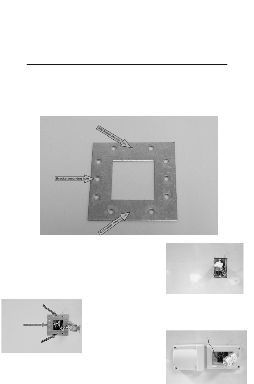
5‐ReaderMountingAccessories
Reader mounting adapter plate – 80-000-1019
In some cases other objects near a receptacle, such as railings or cabinets, will prevent
the Reader from being installed in its default position or orientation. RadarFind Readers
may be hard wired at a 90 degree angle over single gang wall receptacles or in any
orientation over quad receptacles with the accessory adapter plate.
1 – Remove PlugSert module from Reader.
2 - Remove cover plate and receptacle mounting screws,
tip receptacle up from wall.
3 – Install adapter plate with tapped 6/32 Reader mounting
holes for desired Reader orientation.
4 – Install Reader onto adapter plate according to the
Hard wired Reader Installation Procedure.

Radarfind Corporation
8/25/2010 PLM Reader Installation Instructions
Copyright © RadarFind Corp 2010 pg. 17
Reader mounting accessories
Note: RadarFind Readers are packaged with standard 6/32 combination head screws for
the center plate retention screw and the four corner anchor screws. Tamper resistant
screws and matching drivers are available as accessories.
Note: The Reader UL 914C approval - for use as an electrical extension ring - when installed as a
direct wired device requires the use of the provided wall anchors on all four corners. The 50-100-
1020 tamper-resistant screws are custom manufactured for use with these UL approved wall
anchors.
RadarFind Reader Accessories
Part Number Description
80-100-1019
Adapter mounting plate for R11-1411 Reader
50-100-1019
(1) 6/32 2” tamper-resistant center plate
screw for R11-1411 Reader
50-100-1020 (4) 6 /32 3” tamper-resistant wall mounting
screws for R11-1411 Reader
50-100-1021 Tamper-resistant screw driver for 50-100-
1019
50-100-1022 Tamper-resistant screw driver for 50-100-
1020 for R11-1411 Reader
80-113-1002 Replacement external power supply for EVN
style Reader # R22-4012

Radarfind Corporation
8/25/2010 PLM Reader Installation Instructions
Copyright © RadarFind Corp 2010 pg. 18
AppendixA–ReaderIndicatorLED
10SecondsON|10SecondsOFFReaderisfunctioningcorrectlyinTap‐Opsmode
1SecondON|4SecondsOFFApplicationisrunningbutnoTimeSync
BlinkON|4SecondsOFFApplicationisrunning,waitingfortopofEpoch
BlinkBlink|8secondsOFFInBootLoader–NoNetwork
Blink10Times|OFFBootLoader5minutesurveybeforesync
1SecondON|BlinkBlinkBootLoaderSynced,waitingforcommandfromCollector

Radarfind Corporation
8/25/2010 PLM Reader Installation Instructions
Copyright © RadarFind Corp 2010 pg. 19
AppendixB–TechnicalSpecifications
Technical Specifications:
Part # - R22-1012
AC supply: 108-130 VAC RMS, single phase 60HZ
Power: 1.2 VA
Double Insulated
Communications: FHSS FCC Subpart 15.249 and 15.247
RF frequency range: FSK channel between 902 and 928 MHz
Transmit power: +8dBm maximum
Antenna: 6 dB gain cardioid
Operating: 0 to 40º C, 5% to 90% RH, non condensing
Dimensions: 5” W x 12.3” L x 2.25” D
(4 mounting holes for wall anchors)
©2008 Radarfind™ Corporation. All rights reserved. Printed in the USA