Multipin2013 Web
2013-07-09
: Radiall Multipin2013 Web Multipin2013_Web
Open the PDF directly: View PDF ![]() .
.
Page Count: 482 [warning: Documents this large are best viewed by clicking the View PDF Link!]

Multipin Connector Series
Radiall Full Line Catalog

Multipin Connector Series
Radiall Full Line Catalog
Our Most Important Connection is with You.™
MULTIPIN


Connectivity has a profound and dramatic impact
on the lives of people throughout the world. Because
of advancements in technology, our lives are more
convenient, more secure, more enjoyable and richer
than ever. The speed of data enables communication
in the most remote areas so people can reach all
corners of the globe, allows for important defense
and security, and facilitates space exploration. But
technology doesn’t just happen. It starts in the mind
with ideas, making connections never considered
in ways that nobody dreamed possible. Seeing the
future in ways previously unimagined is the act of
innovation and it begins with people –the inventors,
the dreamers, the pioneers and the engineers–
enriching the lives of billions. At Radiall, we have
one single, solitary mission; Empower the people
that enrich our lives. Enable their innovation by
providing reliability and durability. Give them
useful information and provide them with valuable
guidance when determining the best course for
success. We don’t invent the future, we enable it.
We inspire innovation, we embrace challenges,
we challenge the conventional and we collaborate
with you to succeed. At Radiall, we’re proud to say
– Our most important connection is with you.

Table of Contents
EPX® series EN4644
Quick Multipin series
HDQX series
NSX - BPX series Arinc 600
MPX series MIL-DTL-83527B, AECMA EN3682
DSX series SAE AS81659, ARINC 404
MMC series
B & MCS-R series
MM & MB series
RTX series EN3716
MIL-DTL series
Index Part Number
1
2
3
4
5
6
7
8
9
10
11
12


1
Our Most Important Connection is with You™
Radiall is a global leader in the design, development and manufacturing of leading edge interconnect solutions.
Dedicated to understanding its customers’ needs since 1952, Radiall has earned the reputation of being “the best of
the best” in engineering ingenuity by providing a constant flow of creative system solutions serving the defense,
telecommunications, aerospace, instrumentation, automotive, industrial, medical and broadcast markets.
Company Profile
Technical information and sales contacts are available at :
www.radiall.com
Best Value-added Services
Collaboration: We work closely with your engineers to understand
your business, your technical needs, and your budgetary issues.
Wide Product Range: We manage our product lines thru the entire
lifecycle in order to offer you a wide selection of standard products
at an affordable cost.
Custom Products: We can tailor products to specific equipment and
application needs.
Global Presence: We’re everywhere you need us, with worldwide
sales, engineering support, R&D in North America, Europe, and Asia,
and manufacturing facilities strategically located in the United States,
Mexico, France, India, and China.
Responsive Support and Service: From the design stage, planning to
post-installation support, we’re with you at every step, whether you
need sales support or engineering expertise.
On-time Delivery: We support your logistical needs so you get the
products when and where you need them.
Warranty: We proudly stand behind our products.
The Best End-to-End
Interconnect Solutions
We offer an extensive range of solutions
that supports the most demanding signal
transmission applications. 4G wireless
infrastructure, active array radars, IED’s
detection, electrical wiring in aircras,
soldier tactical radios, in-vehicle
communications networks, and magnetic
resonance imaging systems are just a few of
the complex applications that we support.
Certifications and Environmental
Radiall is ISO 9001: 2008 certified and dedicated to continuous
improvement programs that have resulted in also being AS9100,
TS16949 and ISO 14001 certified. In addition, Radiall is committed
to investing in its people, future technologies and the environment,
such as being RoHS (Restriction of Hazardous Substances) and REACH
(Registration, Evaluation, Authorization and Restriction of Chemical
substances) compliant.
RF coaxial connectors
Fiber optic connectors and transceivers
Coaxial and fiber optic cable
assemblies and harnesses
High frequency microwave components
Coaxial switches, including the
smallest and most reliable SPDT relay
Multipin rectangular connectors
Rack and panel connectors
Antennas for tactical networks,
aerospace and instrumentation

2
Aerospace Defense Industrial Space Telecom Instrumentation Medical
Radiall has a global manufacturing
presence. Our International sales
network and qualified distributors
cover every region around the world.
The result is quick and insightful
answers to all your requests.
Radiall at a Glance
Worldwide Presence
Market Focus
Radiall Technologies
Milling
Plating & plastic metallization
Molding
Characterization
Polishing
Laser, ultrasonic, vapor, soldering
Stamping
Thin & thick film processes
Etching on Si
Thick film on AlN
Test & measurement
Simulation
Cable & PTFE wrapping
Automatic assembly
Micro-machining
International Sales Network
Low cost facilities
Local manufacturing, logistics and
technical support
North America Europe
Asia
3
A Global Range to Meet Your Needs
Radiall proudly offers the widest
range of RF Coaxial Connectors
in the Industry with over 12,000
part numbers and 72 product
series including AEP® Mil QPL connectors. These
precision-made components are a significant part
of our heritage and essential to who we are.
Radiall has a wide range of coaxial
devices, including terminations,
attenuators, and couplers using
standard interfaces from low to
high power. Our state of the art techniques enable
us to produce microwave components for use in
commercial, military, and space applications.
Radiall has an unmatched range
of rack and panel connectors
and the most innovative modular
and tool-less connectors used
in harnesses and equipment connections. Our
modern designs combine light weight, high
performance levels and user friendly features
to simplify even the most complex connections.
Industry leaders across the
globe recognize the Radiall
brand for quality, reliability,
and performance. Our Space
Qualified passive product offering includes a wide
range of coaxial connectors, cable assemblies,
microwave components, and switches with
a frequency range up to Ka band.
The combination of design
and manufacturing of RF and
microwave cables as well as
multipin connectors (EPX, ARINC
404 and 600) allows Radiall to be a specialist
of harnesses for onboard or land equipment or
communications systems. All types of contacts
can be used and mixed such as signal, power,
RF, quadrax, fiber optic...
Radiall designs and supports
high performance end-to-end
Optical Interconnect solutions. Our
offer includes standard interfaces,
termini, connectors, harnesses and custom design
optical links and subsystems. The flexibility and
high quality of our product range supports harsh
environments and demanding applications.
Active Optical Solutions
Optimized by D-Lightsys® for
harsh environments. From optical
transceivers to the world’s smallest
parallel optics, D-Lightsys® technologies support
the most challenging applications, including
harsh environments and avionics applications.
Radiall has an extensive range of
cable assemblies with outstanding
electrical performance, low loss,
and high frequency. Our range
includes flexible, semi rigid and handformable
cable assemblies. Our TestPro™ range meets the
stringent requirements needed for test and lab
applications.
Radiall provides highly reliable
antenna solutions for industrial
and military applications. Our
solutions include Line-Of-Sight
tactical communications, vehicular mount, GPS,
telemetry, and mesh networks. For optimum
performance requirements, Radiall offers
custom antenna solutions and support.
All Radiall switches provide
exceptional reliability and
performance. A unique modular
and patented design of the actuator
and transmission link enables Radiall to guarantee
operation up to 10 million cycles with excellent
repeatability, while reducing delivery times.
Harnesses
RF Coaxial Connectors
Microwave Components
Multipin Connectors
Space Qualified
RF & Microwave Switches
Antennas
RF Cable Assemblies
D-Lightsys®
Fiber Optics
4
The multiple bag or box contains 20, 50, or 100 of each component
part in separate bags.
BULK BAG OR BOX OF 100 PIECES BODY + CRIMP FERRULE + CENTER CONTACT
Labeling
Labeling has an important role in packaging. It has to supply all
the necessary information in a clear and concise way. All of our
packages are identified with the Radiall name, part number, lot
number and quantity.
Shipping information
Unless otherwise stated, shipping lead times may vary depending on the location and time zone in which products
are stocked or manufactured. The packaging defines the container of first level of a product. Radiall offers five types
of standard packaging.
Products are arranged in an anti-static polyester blister tape covered
with a ribbon defender. The set is then rolled up on a polyester reel
which can receive 100, 500, 1800 or 3000 parts depending on the model.
This packaging, dedicated to surface mount components is compatible
with all pick and place automatic machines. It is CEI 286-3 compliant.
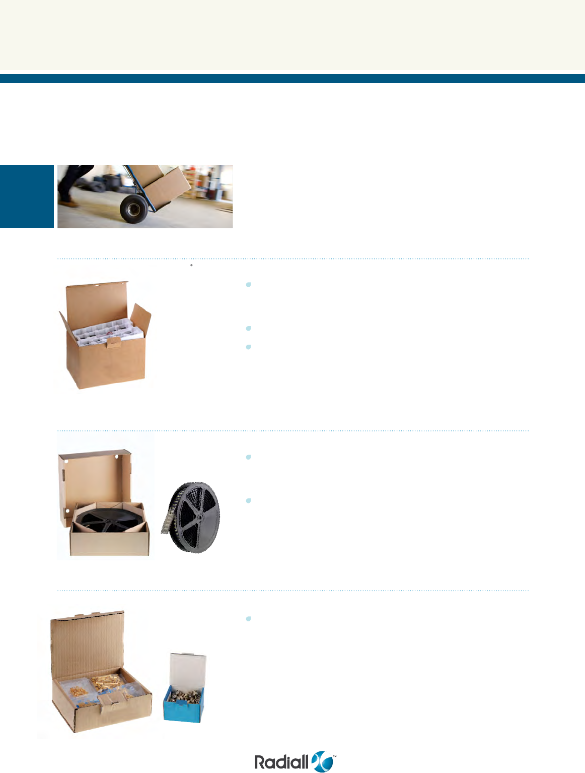
This specific packaging is suitable for large or fragile connectors.
Products are vertically arranged in custom trays, providing protection
against shock and making it easy to quickly count quantity.
They are covered by an anti-dust lid or wrapped with a plastic film.
This packaging is available for specific types of connectors when
standard packaging might cause damage during shipping.
Packaging
24 piece blister tray
500 piece reel
Blister tray
Bulk bag
Tape and reel
DEDICATED TO LARGER CONNECTORS ABILITY TO STACK SEVERAL TRAYS WITHOUT DAMAGING THE CONNECTORS

5
Shipping box
Radiall has designed multiple boxes
for optimum packaging and protection.
These boxes are available in various
optimized sizes.
• Eco friendly design
Labeled tape makes it easy to identify
Radiall goods. Printing is minimized in
order to limit the use of toxic substances.
All boxes can be recycled (except for
the adhesive).
• Each product part number has a
dedicated carton box adapted to the size
of its packaging
• All individual boxes are typically placed
in size 20L shipping boxes (40x30x20 cm).
Packaging
FOR MULTI-PART PRODUCTS EASY TO OPEN IDEAL FOR IN THE FIELD ASSEMBLY
Pre-cut unit bag (no
cutting tool required to open)
This bulk packaging is suitable for small connectors Radiall offers
four types of blister bulk pack depending on the configuration of
the product and the number of pieces (10, 20, 50, or 100).
All connectors can be ordered in unit bags. It is an individual
tear-proof polyethylene bag, which holds the connector and all
of the component parts for that connector.
Unit packaging must be specified when ordering: add « W » at the
end of the part number (except for adapters and specific products).
Three compartments
blister bulk pack of 20 pieces
unit bag
Blister bulk pack
Unit packaging
6
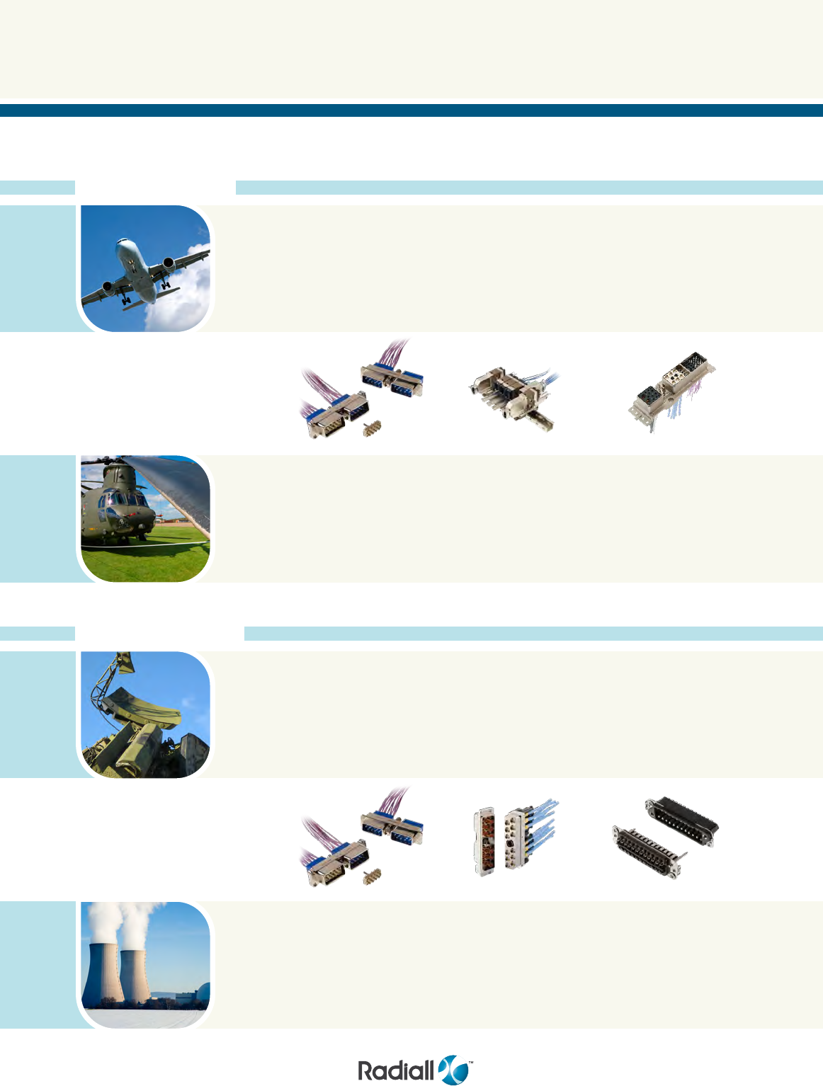
Applications
On-board applications
On-ground applications
Radiall’s vast experience and expertise are reflected in a wide range of rectangular multipin connectors for on-board as
well as on-ground applications.
Civil Aerospace
Industrial
B
- Avionics
- Flight management
- Radar
- Weapons systems
NSX - ARINC 600
- Avionics
- Aerospace general
purpose
- IFE
- Flight management
HDQX
- Avionics
- Flight management
- Radar
- Weapons systems
QM
- Airframe production
break
- Aerospace general
purpose
- IFE
Military Aerospace
Radars
B
- Avionics
- Flight management
- Radar
- Weapons systems
EPX® - EN4644
- Airframe production break
- Avionics
- Aerospace general purpose
- IFE
- Power & flight management
- Radar
EPX® - EN4644
- Power management
- Avionics
- Flight management
- Radar
- Weapons systems
EPX® - EN4644
- Avionics
- Flight management
- Radar
- Weapons systems
7
Applications
DSX - MIL-C-81659
ARINC 404
- Avionics
- Displays
- Aerospace general purpose
- IFE
- Flight management
RTX - MIL-STD-1553
- Radar
- Aerospace general
purpose
HDQX
- Avionics
- Aerospace general
purpose
- IFE
- Flight management
- Radar
RTX - MIL-STD-1553
- Radar
- Weapons systems
MM MB
- Avionics
- Flight management
- Radar
- Weapons systems
MM MB
- Avionics
- Flight management
- Radar
- Weapons systems
DSX - MIL-C-81659
ARINC 404
- Avionics
- Displays
- Flight management
MPX - MIL-C-83527
- Avionics
- Flight management
MMC
- Avionics
- Flight management
- Radar
- Weapons systems
Test Equipment
MCSR
- Avionics
- Flight management
- Radar
- Weapons systems
MCSR
- Avionics
- Flight management
- Radar
- Weapons systems

8

EPX® Series
SECTION 1
EN4644

SECTION 1 TABLE OF CONTENTS
1-3
Our Most Important Connection is with You.™
Go online for data sheets & assembly instructions Visit www.radiall.com and enter the part number
Introduction .................................................................................................................... 1-5
Disconnect applications ....................................................................................................... 1-6
Rack and panel applications .................................................................................................. 1-7
EPX® SERIES
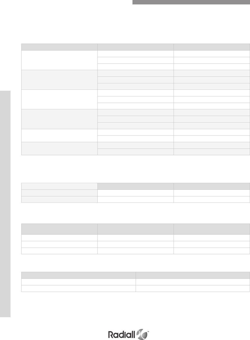
Technical characteristics for disconnect connectors ......................................................................... 1-8
- Electrical characteristics ..................................................................................................... 1-8
- Mechanical characteristics ................................................................................................... 1-8
Technical characteristics for rack & panel connectors ....................................................................... 1-9
- Electrical characteristics ..................................................................................................... 1-9
- Mechanical characteristics ................................................................................................... 1-9
Technical characteristics for inserts & contact ............................................................................. 1-10
- Electrical characteristics ................................................................................................... 1-10
Mechanical characteristics .................................................................................................. 1-11
INSERTS
Insert selection table ......................................................................................................... 1-12
How to order EPX® inserts .................................................................................................. 1-13
EPX® insert arrangements .......................................................................................... 1-14 to 1-16
CONTACTS
Signal & power crimp contacts .............................................................................................. 1-17
Oversized and reduced Crimp Barrel contacts ............................................................................. 1-18
Coaxial crimp contacts ....................................................................................................... 1-19
Twinax and triax crimp contacts ............................................................................................. 1-20
Quadrax & BMA crimp contacts ............................................................................................. 1-21
LuxCis® fiber optic contacts ................................................................................................. 1-22
Signal PC tail contacts ....................................................................................................... 1-23
Quadrax size 8 PC tail contacts .............................................................................................. 1-24
Filler plugs and sealing plugs ............................................................................................... 1-24
Contacts for GbE link Focus ................................................................................................. 1-25
Contents

EPX® SERIES
1-4
Our Most Important Connection is with You.™
Go online for data sheets & assembly instructions Visit www.radiall.com and enter the part number
Contents
DISCONNECT APPLICATION
EPXA product overview ..................................................................................................... 1-26
EPXB1 product overview .................................................................................................... 1-27
How to order EPXA & EPXB1 shell ........................................................................................... 1-28
How to order EPXA & EPXB1 assembly kit ............................................................................... 1-29
Contacts termination for EPXB1 ........................................................................................... 1-30
EPXA shell dimensions ...................................................................................................... 1-31
EPXB1 shell dimensions ..................................................................................................... 1-32
EPXA & EPXB1 polarization code .......................................................................................... 1-33
EPXA & EPXB1 accessories ....................................................................................... 1-34 to 1-35
EPXB2 Disconnect ........................................................................................................... 1-36
EPXB2 product overview .................................................................................................... 1-37
How to order EPXB2 shell ...................................................................................................1-38
How to order EPXB2 assembly kit ..........................................................................................1-39
Contacts termination for receptacles ......................................................................................1-40
EPXB2 metallic shell dimensions .......................................................................................... 1-41
EPXB2 composite shell dimensions ....................................................................................... 1-42
EPXB2 polarization code .................................................................................................... 1-44
EPXB2 accessories .......................................................................................................... 1-45
EPXB2 spare parts .......................................................................................................... 1-46
Tools ........................................................................................................................... 1-47
RACK & PANEL APPLICATION
EPXB1 product overview .................................................................................................... 1-48
EPXB2 product overview .................................................................................................... 1-49
EPXB3 product overview .................................................................................................... 1-50
EPXB4 product overview .................................................................................................... 1-51
How to order EPXB1, B2, B3 & B4 shell ................................................................................... 1-52
How to order EPXB1, B2, B3 & B4 assembly kit .......................................................................... 1-53
Contacts termination for EPXB1, B2, B3 & EPXB4 plugs ............................................................... 1-54
EPXB1 shell dimensions + panel cut-out ................................................................................. 1-55
EPXB2 shell dimensions + panel cut-out ................................................................................. 1-56
EPXB3 shell dimensions + panel cut-out ................................................................................. 1-57
EPXB4 shell dimensions + panel cut-out ................................................................................. 1-58
EPXB panel cut-out coding ................................................................................................. 1-59
EPXB polarization code ..................................................................................................... 1-60
Rack & panel accessories .......................................................................................... 1-61 to 1-62
EPX® galley product overview ............................................................................................. 1-63
How to order EPX® galley connector ..................................................................................... 1-64
Dimensions and panel cut out .............................................................................................. 1-65
Multigang EPX connectors .................................................................................................. 1-66

EPX® SERIES
1-5
Our Most Important Connection is with You.™
Go online for data sheets & assembly instructions. Visit www.radiall.com and enter the part number.
Radiall is recognized in the Aerospace and Defense industries for offering one of the broadest
innovative product portfolios for connector interconnect solutions. The benefit of our experience with
ARINC connectors permits Radiall to provide customers with a strong and global solution.
The EPX® series offers a wide range of solutions based on two insert sizes with a large variety of
shells and contacts. This product range provides an excellent trade-off between the number of
available contacts and the space used. The EPX® series is completely modular and expandable.
The EPX® series connectors are standardized by the EN4644 European standard.
A high density solution compared to circular connectors:
- Slim shell design with high contact density
- Stackable shells do not require additional space for locking and unlocking the connectors
A cost saving and user-friendly solution:
- Inserts can be wired in the workshop and later installed in the shells
- A common panel cut-out simplifies the connector installation
- Inserts can be easily installed and removed from the shell
- Inserts and shells are keyed to prevent mis-mating
- Standard Mil spec tools for contact crimping and contact insertion/extraction
- Field replaceable sub-assemblies
- Vibration resistant self-locking threads
A modular concept with a large variety of options:
- Shell can accommodate a wide variety of inserts for signal, power, coax, data bus, fiber optic and
high frequency BMA contacts
- Optional ground blocks (to meet the FAA HIRF requirements)
- Pin and socket inserts can be installed in either plug or receptacle shells (pin contacts are always
fitted in the pin insert)
EPX® a versatile solution available in two different versions:
- Aluminium
- Composite
EPXB:
5 shells #2 with 2*48 Cts
--> Total Cts: 480
--> Total surface: 96.90 * 91.80 = 8895.42 mm2
Gives 18.53 mm2/contact
38999 :
4 shells #23 with 100 Cts
--> Total Cts: 400
--> Total surface: 96.00 * 96.00 = 9216 mm2
Gives 23.04 mm2/contact
Introduction
EPX® SERIES
1-6
Our Most Important Connection is with You.™
Go online for data sheets & assembly instructions Visit www.radiall.com and enter the part number
PCB-cableCable-cable
EPXA insert EPXB insert
EPXA connector
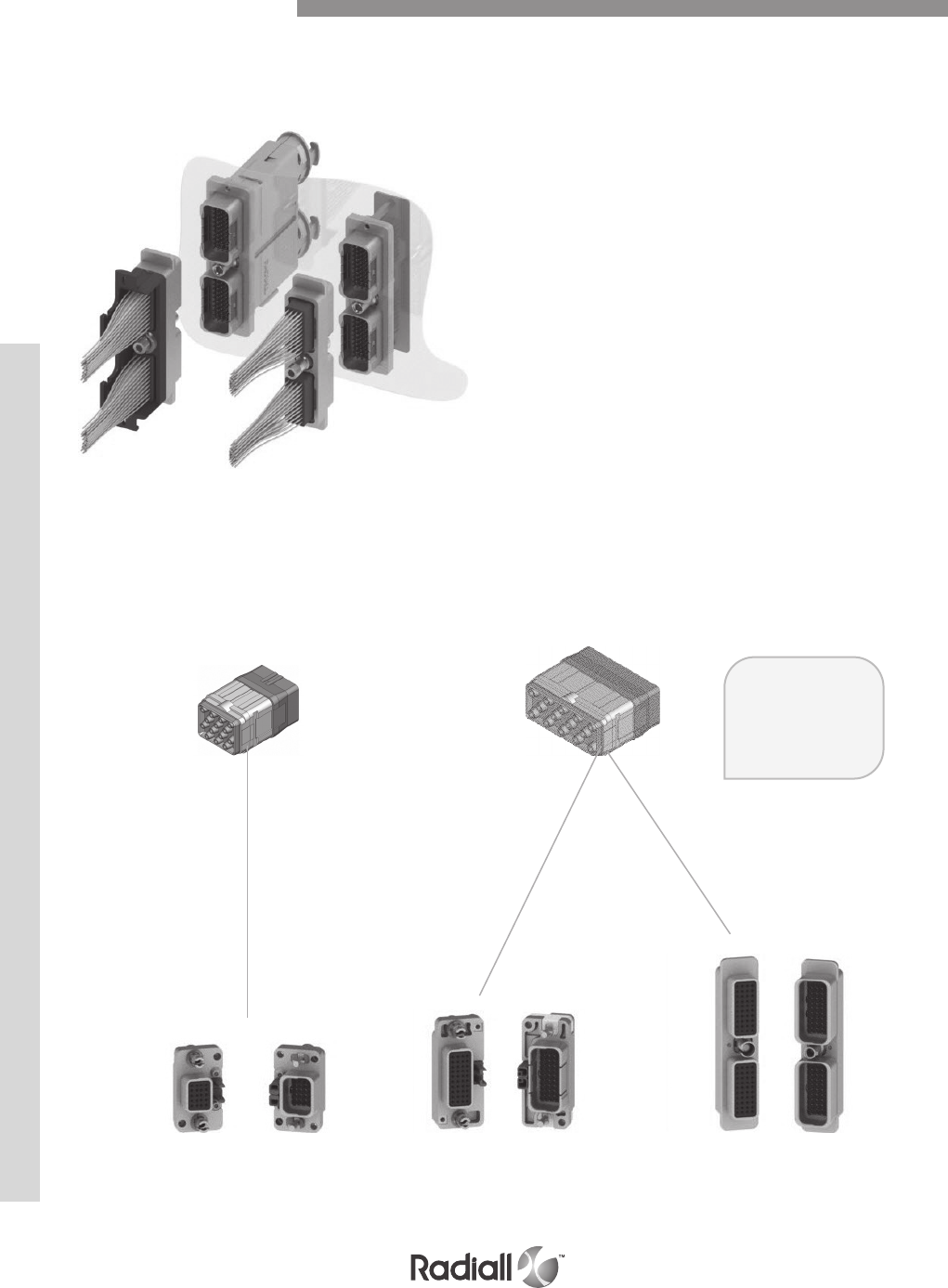
EPX® connectors (EPXA, EPXB1 and
EPXB2) are specially designed to be used
in cable-cable disconnect applications and
PCB-cable disconnect applications.
The principle of EPX® disconnect
connectors is that the locking system
is located on the connector itself.
EPX® connectors for disconnect
applications address three main needs:
- Compactness: the design of the locking
system allows an access from the back
of the shell so that connectors can be
stacked. Space can be easily saved
- Modularity: connectors use similar tools and
accessories so that spare parts are reduced
- Ease of assembly: when on a panel, the connector
is easy to mate with the use of a standard Allen
wrench tool (available at Radiall or anywhere)
The modularity of this series allows you to
configure a connector with higher performances
(environmental, grounding blocks, shell mountings,
etc). Several accessories offer you the possibility
to create harnesses, like the 38999 series.
EPXB1 connector EPXB2 connector
EPXB inserts
fit in any EPXB
disconnect
connector
Disconnect Application
EPX® SERIES
1-7
Our Most Important Connection is with You.™
Go online for data sheets & assembly instructions. Visit www.radiall.com and enter the part number.
In response to the need of system miniaturization
and new equipment design, Radiall introduces
its new rack and panel connectors dedicated to
Line Replaceable Module (LRM) applications.
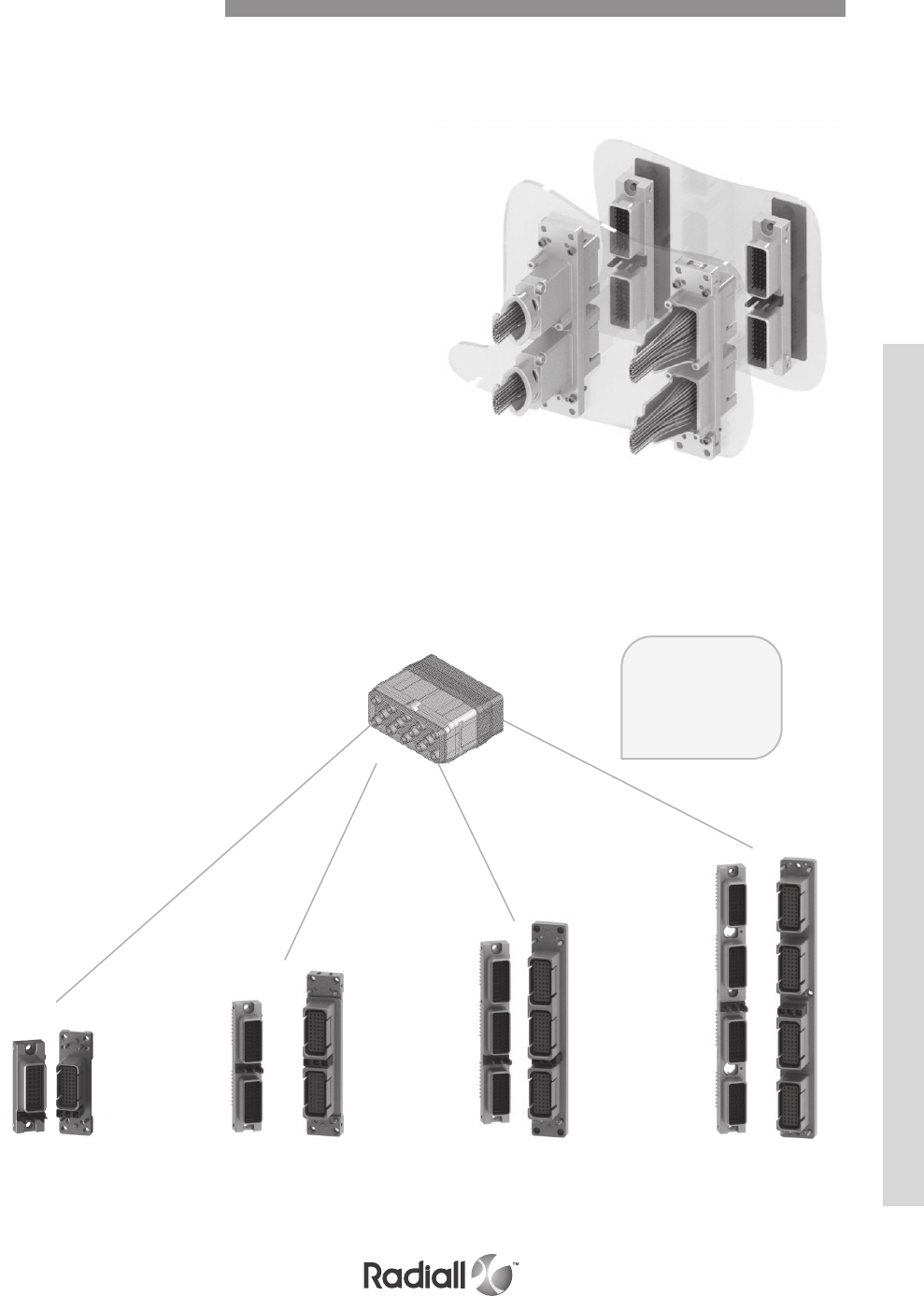
The EPX® rack and panel connectors are intended
for blind mate applications. The plug connector
is designed to be used in a Line Replaceable
Module (LRM) while the receptacle is installed on
the aircraft rack. There is no locking mechanism
on these blind mate connectors, that feature is
part of the equipment interface to the aircraft.
Radiall rack and panel modules offer:
- A wide range of connectors from size 1 to 4
based on the same design. They all use the
same accessories, polarization and mounting
style in order to standardize the EPX® series
- Reliable system: the polarization device
prevents any mounting mistakes between
the panel and the receptacle shell, and also
between the plug and the receptacle shells
- Modularity in mounting EPX® connectors:
EPX® rack and panel receptacles feature
Arinc 600 functionality combined with a
space saving design which provides several
styles of mounting (fixed or float mount)
EPXB1 connector EPXB2 connector EPXB3 connector EPXB4 connector
EPXB inserts
fit in any EPXB
rack & panel
connector
Equipment side
Aircraft side
EPXB insert
Rack and Panel Application
EPX® SERIES
1-8
Our Most Important Connection is with You.™
Go online for data sheets & assembly instructions Visit www.radiall.com and enter the part number
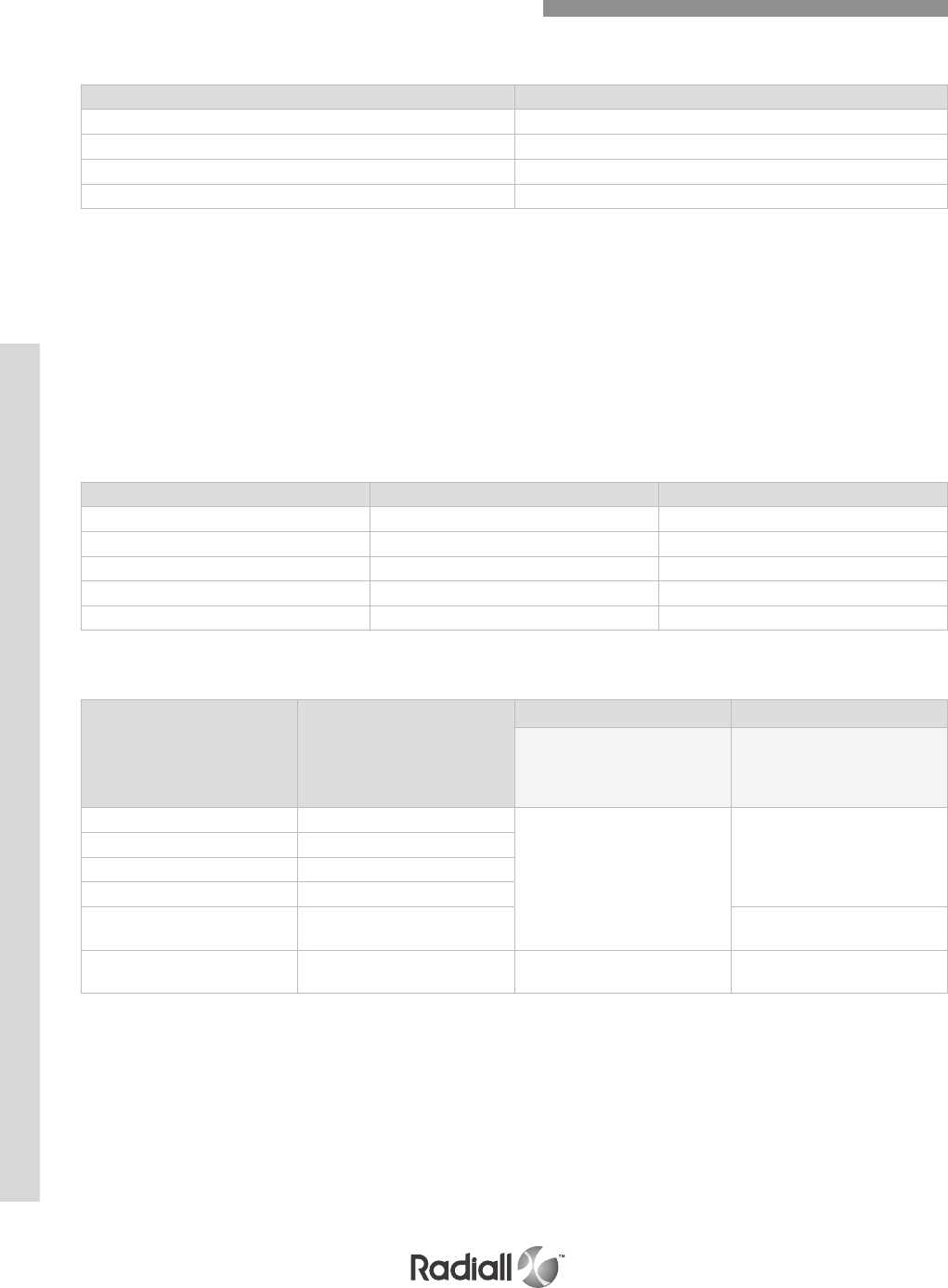
ELECTRICAL CHARACTERISTICS
EMI shielding effectiveness EN2591-213
Frequency (MHz) Leakage attenuation (dB)
100 65
200 & 300 63
400 62
500 & 600 60
OTHER CHARACTERISTICS
- Shell to shell conductivity < 2.5 mΩ, operating voltage: 400 Vrms or 500 Vdc at sea level,
according to EN2591-205
- Voltage stability (ground block): Maximum variation 4mV according to SAE AS 81714 (MIL-T-81714)
- Lightning stike: - 5kA - 1600V for EPX® connectors in aluminium version
- 3kA - 1600V for EPX® connectors in composite version
MECHANICAL CHARACTERISTICS
Mating/unmating
Shell type Material Mating/Unmating
EPXA Aluminium 100 cycles
EPXB1 Aluminium 100 cycles
EPXB1 Composite 100 cycles
EPXB2 Composite 100 cycles(1)
EPXB2 Aluminium 100 cycles(1)
VIBRATION & SHOCK
Vibration Shock
Shell type Material
For 8 hrs on each of the
3 axis/ interruption
<1s EN2591-403
EIA 364-28
3 shocks on each axis
EN2591-402 EIA 364-27
EPXA Aluminium
Acceleration 27.8g
(test condition 6 letter G)
Shock amplitude 50g /duration
11ms
EPXB1 Aluminium
EPXB1 Composite
EPXB2 Composite
EPXB2 Aluminium Shock amplitude 300g /duration
3ms
Disconnect EPX® with
Quadrax contacts /Acceleration 16.9g
(test condition 5 letter E)
Shock amplitude 50g /duration
11ms
NOTE:
(1) 500 mating cycles possible when using lubricant (as per the standard Mil-spec DOD G 24508) on locking device
Technical Characteristics for Disconnect Connectors
EPX® SERIES
1-9
Our Most Important Connection is with You.™
Go online for data sheets & assembly instructions. Visit www.radiall.com and enter the part number.
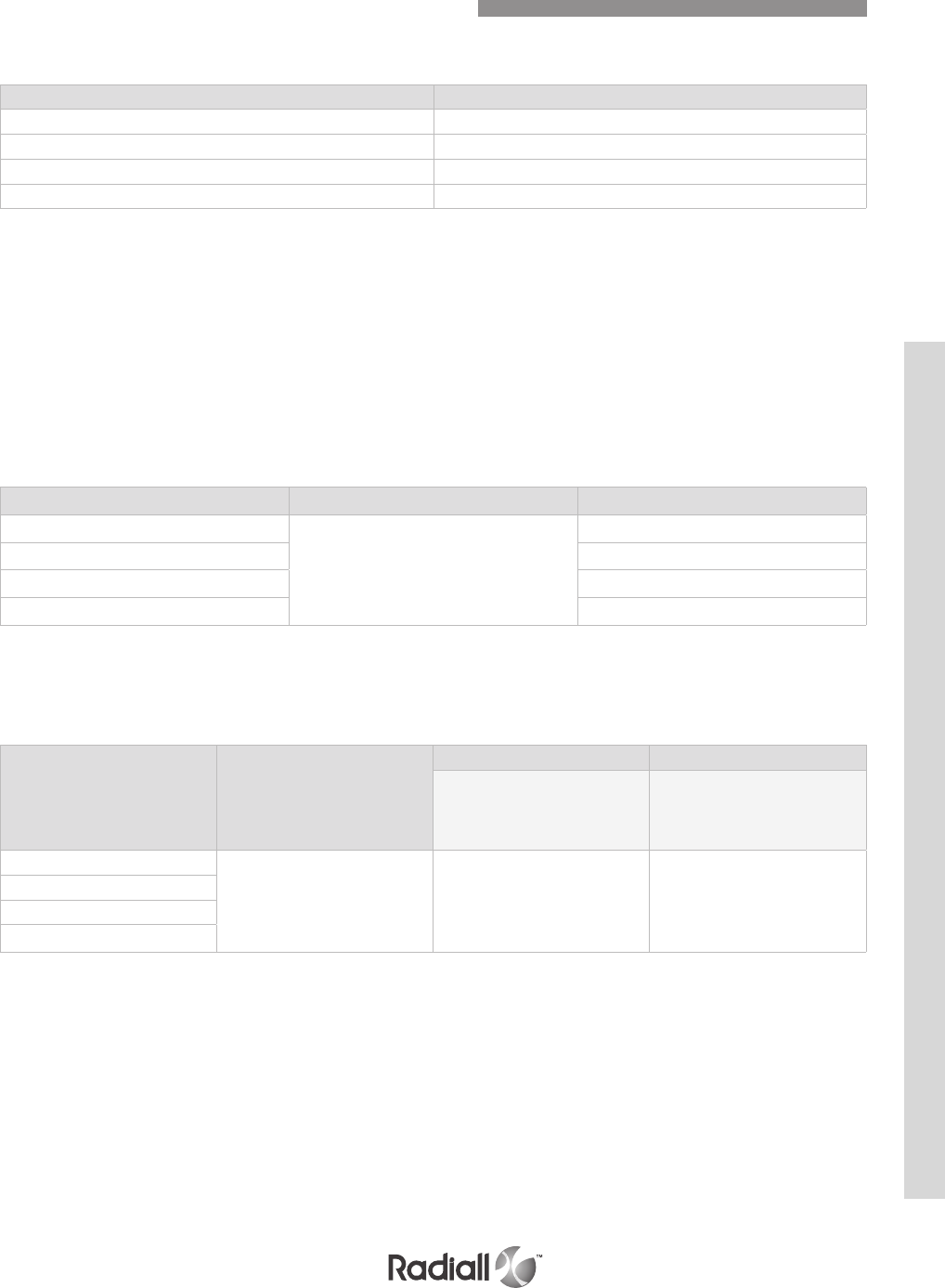
EMI shielding effectiveness en2591-213
Frequency (MHz) Leakage attenuation (dB)
100 65
200 & 300 63
400 62
500 & 600 60
OTHER CHARACTERISTICS
- Shell to shell conductivity < 2.5 m Ω, operating voltage: 400 Vrms or 500 Vdc at sea level,
according to EN2591-205
- Voltage stability (ground block): Maximum variation 4mV according to SAE AS 81714 (MIL-T-81714)
- Lightning stike: - 5kA - 1600V for EPX® connectors in aluminium version
- 3kA - 1600V for EPX® connectors in composite version
MECHANICAL CHARACTERISTICS
Mating/unmating
Shell type Material Mating/Unmating
EPXB1
Aluminium
500 cycles
EPXB2 500 cycles
EPXB3 500 cycles
EPXB4 500 cycles
The minimum mating forces are described in the EN4644 standard and depends on the
connector size and insert arrangement. Consult Radiall for more information.
Technical Characteristics for Rack & Panel Connectors
ELECTRICAL CHARACTERISTICS
Shell type Material
Vibration Shock
For 8 hrs on each of the
3 axis/ interruption
<1s EN2591-403
EIA 364-28
3 shocks on each axis
EN2591-402 EIA 364-27
EPXB1
Aluminium Acceleration 16.9g
(test condition 5 letter E)
Shock amplitude 50g /duration
11ms
EPXB2
EPXB3
EPXB4
VIBRATION & SHOCK
EPX® SERIES
1-10
Our Most Important Connection is with You.™
Go online for data sheets & assembly instructions Visit www.radiall.com and enter the part number
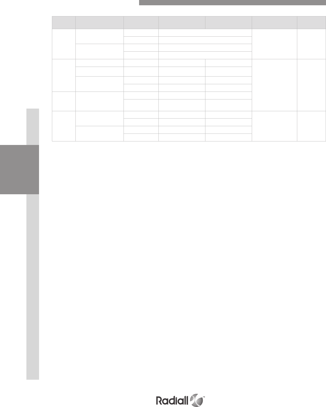
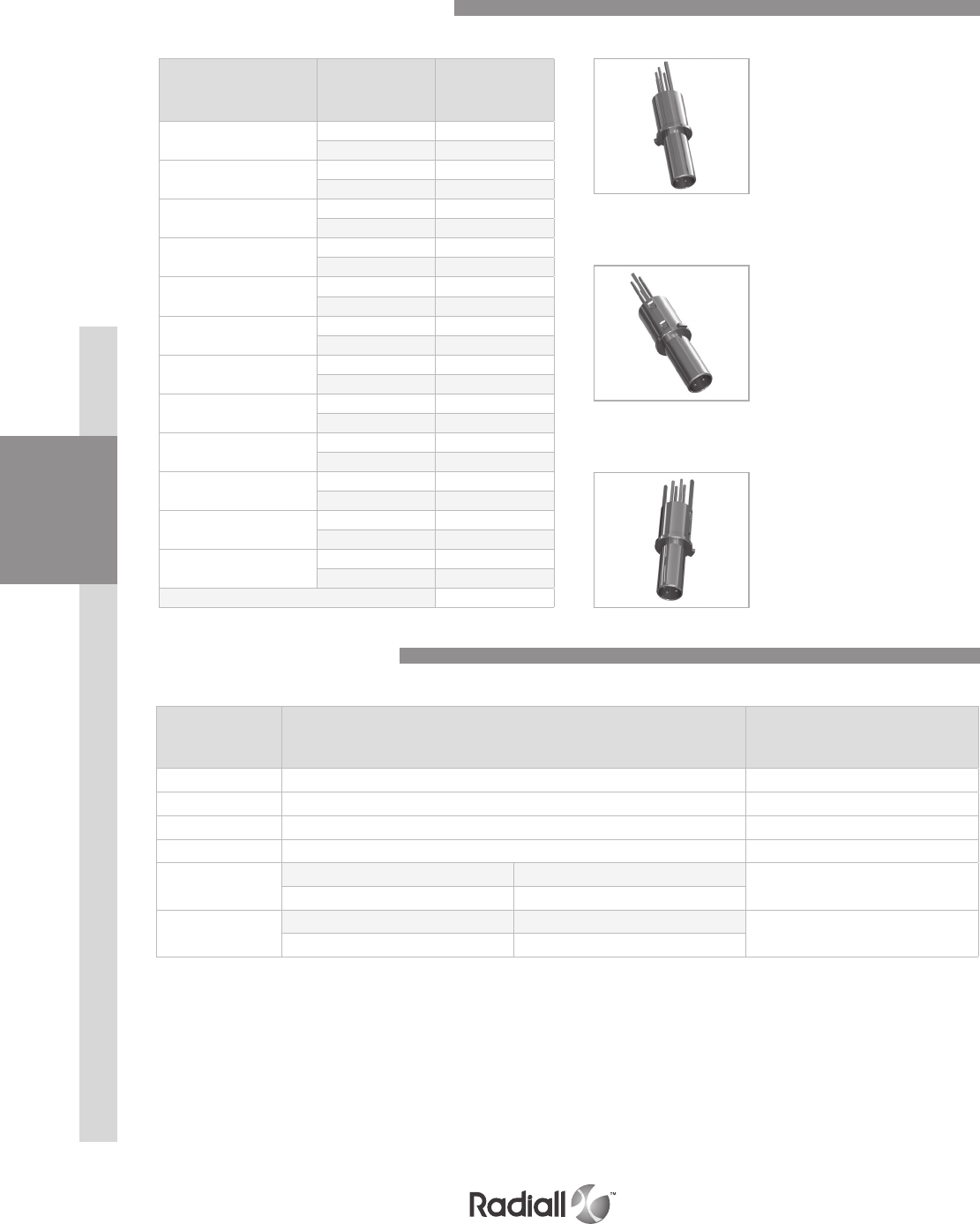
ELECTRICAL CHARACTERISTICS
Electrical characteristics conform to SAE AS 39029 (MIL-C-39029 type A)
Contacts conform to EN3155-076 and EN3155-077
CONTACTS
Contact size Wire size Max current Amps
22
AWG22 5
AWG24 3
AWG26 2
20
AWG20 7.5
AWG22 5
AWG24 3
16
AWG16 13
AWG18 10
AWG20 7.5
12
AWG12 23
AWG14 17
AWG16 13
8AWG8 46
AWG10 33
5AWG8 80 (1)
AWG10 33
NOTE:
(1) Size 5 contacts are not part of SAE AS 39029 (MIL-C-39029 type A). They are qualified by Radiall to 80 Amps
GROUND BLOCK CONTACT
Contact with wire size Max current Amps
Contact to contact Contact + AWG20 7.5
Contact to mounting surface Contact + AWG20 7.5
DIELECTRIC WITHSTANDING VOLTAGE EN2591-207 EIA 364-20 with leakage current < 1mΩ
Level Environmental inserts voltage
(VRMS)
Non-environmental voltage
(VRMS)
Sea level 1500 1500
50,000 feet 800 600
70,000 feet 800 300
INSULATION RESISTANCE EN2591-206 EIA 364-21
Temperature Insulation resistance
Ambient temperature > 5000 M
175°C (+347°F) > 200 M
Technical Characteristics for Inserts & Contacts
EPX® SERIES
1-11
Our Most Important Connection is with You.™
Go online for data sheets & assembly instructions. Visit www.radiall.com and enter the part number.
Contact retention EN2591-409 EIA 364-29 in terminated connectors.
Contact size Retention force Max displacement
Ground block 88N (20 lbs) 0.30mm (.012 in.)
22 53.4N (12 lbs) 0.38mm (.015 in.)
20 89N (20 lbs) 0.38mm (.015 in.)
16 111.2N (25 lbs) 0.38mm (.015 in.)
12 133.45N (30 lbs) 0.38mm (.015 in.)
8133.45N (30 lbs) 0.38mm (.015 in.)
5133.45N (30 lbs) 0.38mm (.015 in.)
- Insert retention: 400N (90 lbs) EN2591-410 EIA 364-35
- Maximum insert displacement in the shell cavity: 0.30mm (.012 in.)
ENVIRONMENTAL CHARACTERISTICS
Temperature
- Temperature range: -65°C/+175°C (-85°F/+347°F) according to EIA364-32 and EN2591-305
- Temperature range: -65°C/+125°C (-85°F/+257°F) for EPXB2 composite shell
and for Rack & Panel EPXB
- Temperature life: 1000 hours at maximum temperature
OTHER CHARACTERISTICS
- Salt spray: 96 hours (nickel-plated aluminium and composite) EN2591-307 EIA 364-26 test
condition A
- Humidity: 10 days with temperature variation from -10°C to +65°C EIA 364-31 Method 4, test
condition B
- Altitude immersion: 3 cycles at 50,000 feet EN2591-314 EIA 364-03
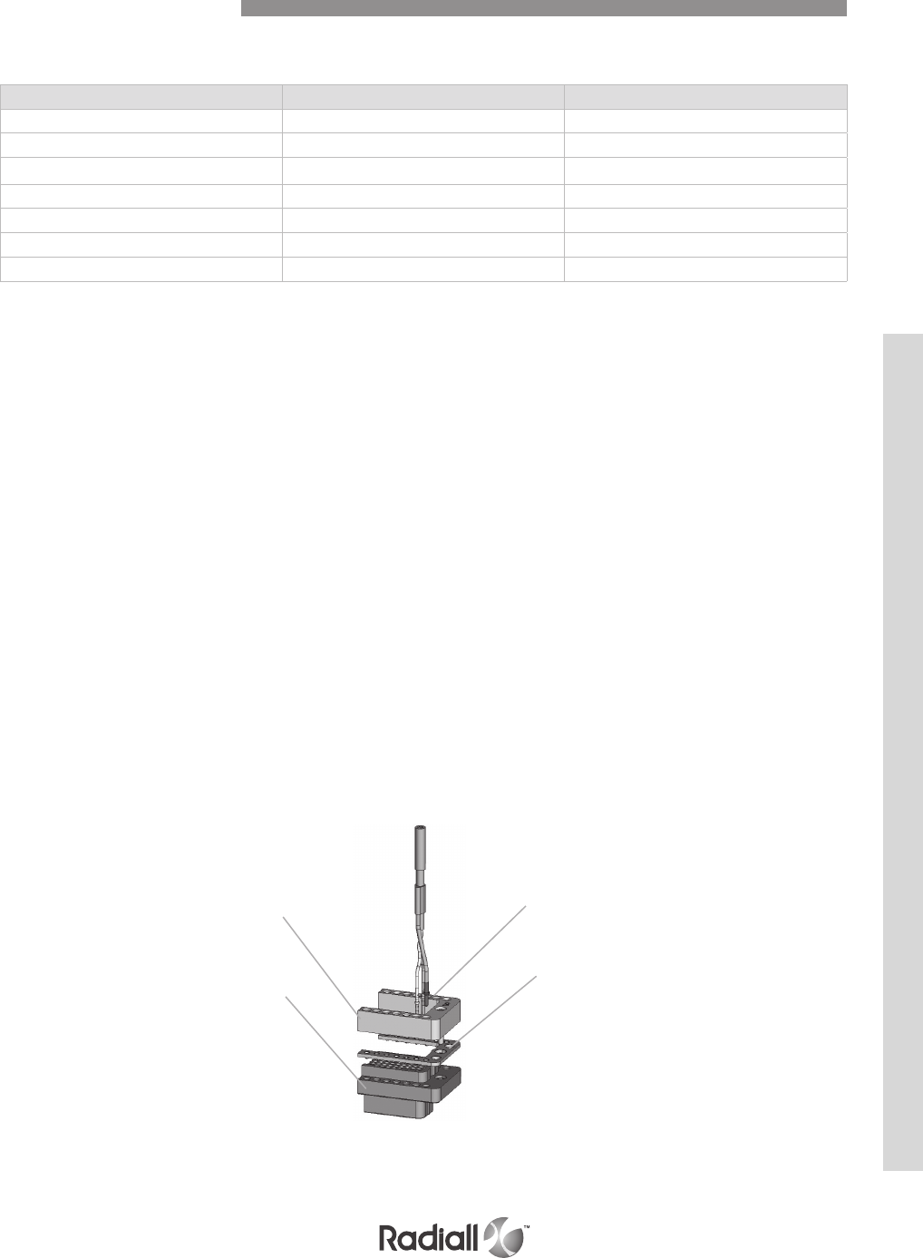
GROUND BLOCK
Radiall provides a unique patented feature by integrating a ground block directly on the shell
This option permits very short ground terminations
Connector Shell
Insulator
M39029/1-101 contacts
Radiall P/N 617221050
Intermediate plate
for grounding
Mechanical Characteristics
RETENTION CHARACTERISTICS
INSERTSDISCONNECT APPLICATIONRACK & PANEL APPLICATION CONTACTS EPX® SERIES
1-12
Our Most Important Connection is with You.™
Go online for data sheets & assembly instructions Visit www.radiall.com and enter the part number
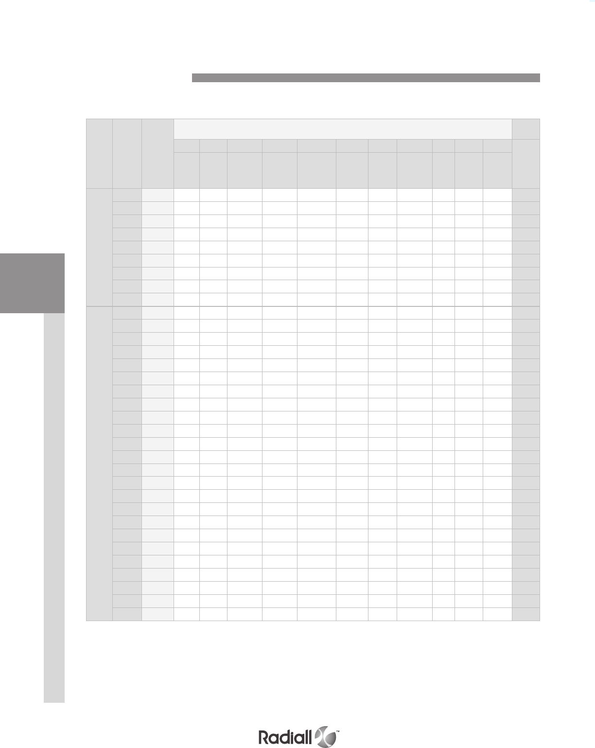
Series
Insert
name
Insert
code
Contact Size & Type (1)
22* 20* 15 or 16* 16 16 12* 8 8 8 5 5
Total
contacts
Signal Power Power or
coax
LuxCis®
fiber optic
Power in
fiber optic
cavity
Power or
coax Power
Quadrax
or
twinax
BMA Coax or
triax Power
EPXA
00 0 0
1C1 A11
1P1 B11
04 C2 2 4
09 D3 6 9
14 E14 14
14M F8 3 3 14
17 G12 517
20 H 20 20
EPXB
00 0 0
C3 A33
P3 B33
3Q3 C33
06 D66
10Q2 E8 2 10
12F6 F6 6 12
F12C G12 12
13C1 H 6 4 2 1 13
13P1 J 6 4 2 1 13
14 K14 14
17 L14 317
20C1 M 19 120
20P1 N 19 120
22 P16 622
22V Q16 622
25P1 R24 125
25Q1 S24 125
28 T22 628
30 U30 30
34 W18 16 34
40 X40 40
48 Y48 48
3T3 Z33
NOTE:
(1) Only contacts marked with an asterisk (*) are included with EPX® inserts
All other contacts must be ordered separately (coax, twinax, quadrax and fiber optic contacts)
Insert name should be used when ordering EPX® insert
Insert code should be used when ordering kit assembly
Insert Selection Table
DISCONNECT APPLICATIONRACK & PANEL APPLICATION CONTACTS INSERTS EPX® SERIES
1-13
Our Most Important Connection is with You.™
Go online for data sheets & assembly instructions Visit www.radiall.com and enter the part number
NOTES:
(1) Inserts are designed for rear release & rear removable contacts
(2) Pin and socket inserts can be installed in either plug or receptacle shell
F6, F12C and 12F6 are only available in E class. “Insert 00 is only available in N class
(3) For EPXA, EPXB1, EPXB3 and EPXB4 shells, use only insert keyed A
For EPXB2 shells, use one insert keyed A and one insert keyed B
ENVIRONMENTAL INSERT
Rear grommet
Pin insert
Interfacial seal
Rear grommet Socket insert
Insert Keying Detail
Keying A
Keying B
EPX B E 40 P B S
Only crimp contacts can be delivered with insert
How to order EPX® inserts
Series prefix
Insert size(1)
A: Insert for EPXA
B: Insert for EPXB1, EPXB2, EPXB3 or EPXB4
Class(2)
E: Environmental
N: Non-environmental (no rear grommet, no interfacial seal)
H: Non-environmental with a rear grommet, available for pin insert only (recommended for crimp contacts)
T: Non-environmental with an interfacial seal, available for pin insert only (recommended for PC tail contacts)
Insert name
Refer to table on page 1-12 for insert arrangements
Insert type
P: Pin
S: Socket
Insert keying(3)
A: Keying A
B: Keying B
Contact
Without code: insert delivered without contacts
S: Signal and power contacts are delivered with inserts but are uninstalled (refer to page 1-12)
Inserts 00, 1C1, 1P1, C3, P3, 3Q3, 12F6, F12C and 3T3 are not available in S contact version
INSERTSDISCONNECT APPLICATIONRACK & PANEL APPLICATION CONTACTS EPX® SERIES
1-14
Our Most Important Connection is with You.™
Go online for data sheets & assembly instructions Visit www.radiall.com and enter the part number
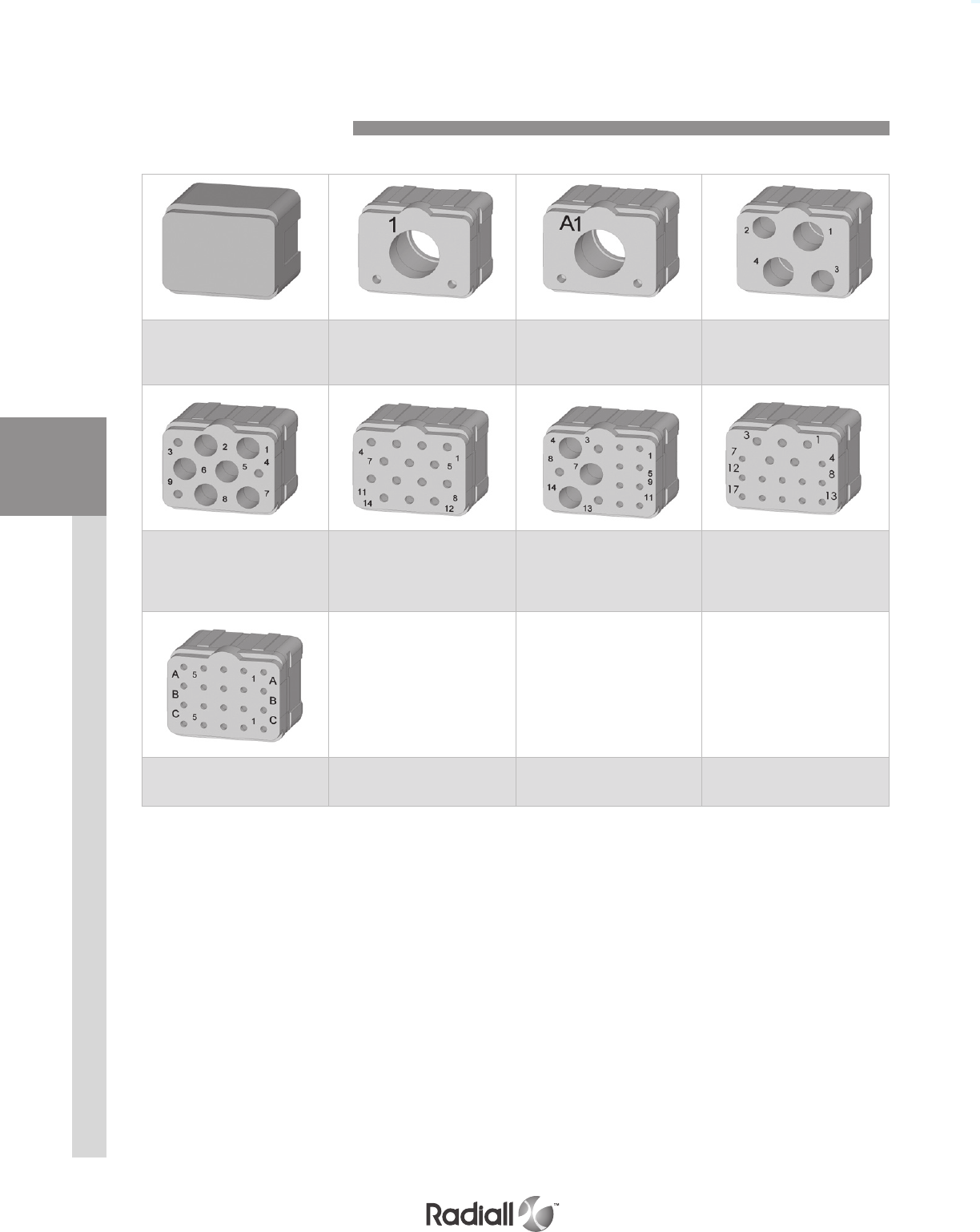
Insert name 00
Insert code 0
Blank insert (1)
Insert name 1C1
Insert code A
1 x size 5 coax contacts
Insert name 1P1
Insert code B
1 x size 5 power contacts
Insert name 04
Insert code C
2 x size 15 or 16 contacts
2 x size 12 contacts
Insert name 09
Insert code D
3 x size 20 contacts
6 x size 15 or 16 contacts
Insert name 14
Insert code E
14 x size 20 contacts
Insert name 14M
Insert code F
8 x size 22 contacts
3 x size 20 contacts
3 x size 15 or 16 contacts
Insert name 17
Insert code G
12 x size 22 contacts
5 x size 20 contacts
Insert name 20
Insert code H
20 x size 22 contacts
EPXA Insert Arrangements
NOTE:
(1) P/N for blank insert is EPXAN00
DISCONNECT APPLICATIONRACK & PANEL APPLICATION CONTACTS INSERTS EPX® SERIES
1-15
Our Most Important Connection is with You.™
Go online for data sheets & assembly instructions Visit www.radiall.com and enter the part number
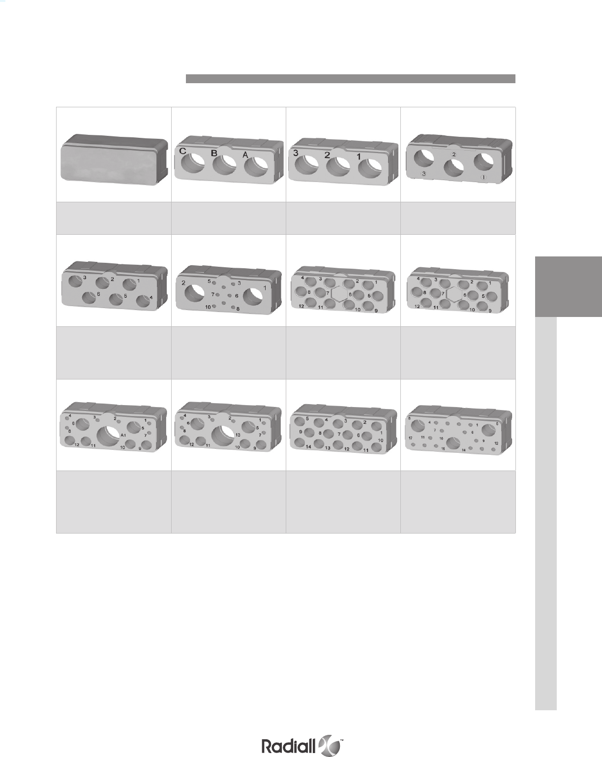
Insert name 00
Insert code 0
Blank insert (1)
Insert name C3
Insert code A
3x size 5 coax contacts
Insert name P3
Insert code B
3 x size 5 power contacts
Insert name 3Q3
Insert code C
3 x size 8 quadrax contacts
Insert name 06
Insert code D
6 x size 12 medium power contacts
Insert name 10Q2
Insert code E
8 x size 20 contacts
2 x size 8 quadrax contacts
Insert name 12F6
Insert code F
6 x size 16 Optical LuxCis ® termini
6 x size 16 special
electrical contacts
Insert name F12C
Insert code G
12 x size 16 Optical
LuxCis® termini
Insert name 13C1
Insert code H
6 x size 20 contacts
4 x size 15 or 16 contacts
2 x size 12 contacts
1 x size 5 coax contact
Insert name 13P1
Insert code J
6 x size 20 contacts
4 x size 15 or 16 contacts
2 x size 12 contacts
1 x size 5 power contact
Insert name 14
Insert code K
14 x size 15 or 16 contacts
Insert name 17
Insert code L
14 x size 20 contacts
3 x size 12 contacts
Full size inserts arrangements are compliant with EN4644
EPXB Insert Arrangements
NOTE:
(1) P/N for blank insert is EPXBN00

INSERTSDISCONNECT APPLICATIONRACK & PANEL APPLICATION CONTACTS EPX® SERIES
1-16
Our Most Important Connection is with You.™
Go online for data sheets & assembly instructions Visit www.radiall.com and enter the part number
Insert name 20C1
Insert code M
19 x size 20 contacts
1 x size 5 coax contact
Insert name 20P1
Insert code N
19 x size 20 contacts
1 x size 5 power contact
Insert name 22
Insert code P
16 x size 20 contacts
6 x size 15 or 16 contacts
Insert name 22V
Insert code Q
16 x size 20 contacts
6 x size 16 contacts
Insert name 25P1
Insert code R
24 x size 22 contacts
1 x size 8 power contact
Insert name 25Q1
Insert code S
24 x size 22 contacts
1 x size 8 quadrax contact
Insert name 28
Insert code T
22 x size 22 contacts
6 x size 15 or 16 contacts
Insert name 30
Insert code U
30 x size 20 contacts
Insert name 34
Insert code W
18 x size 22 contacts
16 x size 20 contacts
Insert name 40
Insert code X
40 x size 22 contacts
Insert name 48
Insert code Y
48 x size 22 contacts
Insert name 3T3 (1)
Insert code Z
3 x size 8 BMA pin contacts
NOTE:
(1) 3T3 pin insert only is available. It is mateable with 3Q3 socket insert
EPXB Insert Arrangements
Full size inserts arrangements are compliant with EN 4644.
DISCONNECT APPLICATIONRACK & PANEL APPLICATION CONTACTS INSERTS EPX® SERIES
1-17
Our Most Important Connection is with You.™
Go online for data sheets & assembly instructions Visit www.radiall.com and enter the part number
Contact size Wire
size Type Part number
full plated
Part number
selectively
plated
Crimping tool Positioner Selec-
tor Ins / ext tool Type
of tool
22
22 Pin 617200 617200100 282281
M22520/2-01 282970
M22520/2-23
4282522
(M81969/14-01) Plastic24 3
26 Socket 617300 617300100 3
20
20 Pin 617221 617221100 282281
M22520/2-01 282971
M22520/2-08
7282522001
(M81969/39-01) Plastic22 6
24 Socket 617320 617320100 5
16
16 Pin 617240 617240100 282291
M22520/1-01 282972
M22520/1-02
6282515
(M81969/14-03) Plastic18 Socket 617340 617340100 5
20 4
Ground
block 20 Pin 617221050 N/A 282281
M225520/2-01 282581015
M22520/2-11 7282886 Metal
Socket N/A N/A
for
optical/
electrical
insert
16
Pin 617235003(1) N/A 282291
M22520/1-01 282581013
6282515
(M81969/14-03) Plastic18 5
20 4
12
12 Pin 617250 617250100 282291
M22520/1-01 282972
M22520/1-02
8282549004
(M81969/14-04) Plastic14 Socket 617350 617350100 7
16 6
8
8Pin 617291002(2&3) N/A R282600000
M22520/23-
01 + Die set
R282650000
M22520/23-02
282588 N/A 282549001 Metal10
Socket 617391002(2&3) N/A
5
8Pin 6172 8 0
(2&4) N/A R282600000
M22520/23-01
+ Die set
R282650000
M22520/23-02
282557020
N/A 282946
(M81969/28-01) Metal
10 Socket 617390(2&4) N/A 282557021
12 Pin 617260001(2&4) N/A 282613 282586003 6
16 Socket 617370001(2&4) N/A 282586005
NOTES:
(1) Electrical contacts for optical inserts are always pin contacts (hermaphrodite)
(2) In order to make these contacts environmental, it is necessary to add a sealing boot. Please contact us for additional information
(3) These power contacts can be used in power inserts only (25P1)
(4) These power contacts can be used in power inserts only (P3, 13P1 and 20P1)
Signal & Power Crimp Contacts
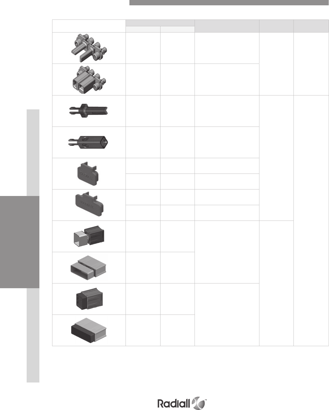
EPX series offers a wide range of contacts compliant with EN3155 and SAE AS 39029. The available
contacts cover aerospace applications for terminating to both cables and printed circuit boards.
- Signal and power contacts
- High frequency with coax, twinax and triax contacts
- Ethernet links with Quadrax contacts
- Optical links with LuxCis® contacts
Discover our brand new range of signal & power contacts with selective gold plating
Features and benefits :
- Significant reduction of cost of ownership
- Reduced dependence on gold rate fluctuation
- No change in the contact crimping or soldering process
Specifications:
- Same contact design as full plated version
- Contact interface gold plated with 1.27m
- For crimp version, no changes are required for the crimping process
- For PC tail version, use of selective plated contacts has no impact on PCB design
- Product qualification is available upon request

INSERTSDISCONNECT APPLICATIONRACK & PANEL APPLICATION CONTACTS EPX® SERIES
1-18
Our Most Important Connection is with You.™
Go online for data sheets & assembly instructions Visit www.radiall.com and enter the part number
Oversized & Reduced Crimp Barrel Contacts
NOTES:
(1) When smaller wire sizes are used on contacts with reduced crimp barrel, the wire will not provide sealing to the grommet. If sealing is
required, please contact Radiall
(2) Electrical contacts for optical insertss are always pin contacts (hermaphrodite)
Contact size Wire size Type Part number fully
plated Crimping tool Positioner Selector Ins / ext tool Type of tool
22
reduced crimp
barrel
28 Pin 617201 (1) 282281
M22520/2-01
282970
M22520/2-23
5
282522
(M81969/14-01) Plastic
30 Socket 617301(1) 4
oversize crimp
barrel
20 Pin 617200200
282281
M22520/2-01
282970
M22520/2-23
5
22 Socket 617300200 4
24 3
20
reduced crimp
barrel
22 Pin 617224001 (1)
282281
M22520/2-01
282971
M22520/2-08
4
282522001
(M81969/39-01) Plastic
24 Socket 617324001 (1) 3
26 3
oversize crimp
barrel
18 Pin 617221200
282281
M22520/2-01
282971
M22520/2-08
5
20 Socket 617320200 5
22 4
16
reduced crimp
barrel
20 Pin 617241 (1)
282291
M22520/1-01
282972
M22520/1-02
5
282515
(M81969/14-03) Plastic
22 Socket 617341 (1) 5
24 4
reduced crimp
barrel for optical
electrical insert
20
Pin 617235002 (&2) 282291
M22520/1-01 282581013
5
22 5
24 4
oversize crimp
barrel
14 Pin 617240200
282291
M22520/1-01
282972
M22520/1-02
6
16 Socket 617340200 5
18 5
DISCONNECT APPLICATIONRACK & PANEL APPLICATION CONTACTS INSERTS EPX® SERIES
1-19
Our Most Important Connection is with You.™
Go online for data sheets & assembly instructions Visit www.radiall.com and enter the part number
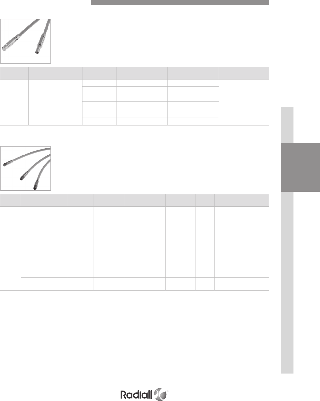
Contact
size Cable type Type Environmental part
number
Non-environmental
part number Ins/ext tool Type
of tool
15-16
RG174-RG179 RG316 Pin 617130
282512 Metal
Socket 617030
RG178 Pin 617131
Socket 617031
GORE/AXON P812817
FILECA F1703-134
FILOTEX SP132868
Pin 617132
Socket 617032
RG178 DT Pin 617133
Socket 617033
UT .047 Pin 617135
Socket 617035
12 UT.085-RG405 Pin 617160 282549004
(M81969/14-04) Plastic
Socket 617060
5
RG58-RG141 Pin 617101001 617101
282946
(M81969/28-01) Metal
Socket 617001001 617001
RG142 - RG400 Pin 617102001 617102
Socket 617002001 617002
RG174-RG316 RG188 Pin 617103001 617103
Socket 617003001 617003
RG178-RG196 Pin 617104001 617104
Socket 617004001 617004
RG180 Pin 617105001 617105
Socket 617005001 617005
Coaxial Crimp Contacts
INSERTSDISCONNECT APPLICATIONRACK & PANEL APPLICATION CONTACTS EPX® SERIES
1-20
Our Most Important Connection is with You.™
Go online for data sheets & assembly instructions Visit www.radiall.com and enter the part number
Contact
size Cable type Type Environmental part
number
Non-environmental
part number Ins/ext tool Type
of tool
12 Triax
ECS0700 Pin 617190010
282549004
(M81969/14-04) Plastic
Socket 617090010
M17/176-00002 Pin 617190012
Socket 617090012
8 Triax
TENSOLITE Pin 617165021 617165020
282549001 Metal
24473/03159X-2 Socket 617065021 617065020
WHITMOR
W26751575
Pin 617165 617165001
Socket 617065 617065001
8 Twinax
ABS0386WF24
& TYCO
1726A1424A
Pin 617165011 620165010
Socket 617065011 620065010
5 Triax
M17/176-0002 Pin 617150001 617150
282946
(M81969/28-01) Metal
Socket 617050001 617050
PAN6421 Pin 617152001 617152
Socket 617052001 617052
Twinax & Triax Crimp Contacts
DISCONNECT APPLICATIONRACK & PANEL APPLICATION CONTACTS INSERTS EPX® SERIES
1-21
Our Most Important Connection is with You.™
Go online for data sheets & assembly instructions Visit www.radiall.com and enter the part number
QUADRAX CONTACTS
BMA CONTACTS
Contact
size Cable type Connector
Type
Environmental
part number
Non-environmental
part number
Frequency
range
Max
VSWR Insertion loss
8
SHF5 - SHF5M(1) Pin(2) 617171011 617171010 DC-18 GHz 1.35 0.13 dB at max frequency
(18 GHz)
RG142 Pin(2) 617171021 617171020 DC-12.4 GHz 1.35 0.11 dB at max frequency
(12.4 GHz)
SHF2.4M(1)/UT.085
Harbour SS405
Times Tflex405
Pin(2) 617171031 617171030 DC-18 GHz 1.35 0.13 dB at max frequency
(18 GHz)
SHF5 - SHF5M(1) Socket 617071011 617071010 DC-18 GHz 1.35 0.13 dB at max frequency
(18 GHz)
RG142 Socket 617071021 617071020 DC-12.4 GHz 1.35 0.11 dB at max frequency
(12.4 GHz)
SHF3(1) Socket 617071041 617071040 DC-18 GHz 1.35 0.13 dB at max frequency
(18 GHz)
Extraction tool 282549001 is used for size 8 BMA contacts
Environmental BMA contacts are all provided with sealing boots
NOTES:
(1) The BMA contacts which can accommodate SHF cables requires a termination by Radiall
(2) BMA can only be installed in modified EPXB Quadrax insert such as 3T3P. Ex: EPXBE3T3PA
Contact size Cable type Type Environmental
part number
Non-environmental
part number Extraction tool in metal
8
Ethernet cable
ABS0972 & ABS1503
Pin 617175011 617175012
282549001
Socket 617075011 620075010
TENSOLITE
NF24Q100
Pin 617175051 617175052
Socket 617075051 620075050
Tensolite NF26Q100
JSF Y18
Pin 617175053 617175054
Socket 617075053 620075021
Quadrax & BMA Crimp Contacts
INSERTSDISCONNECT APPLICATIONRACK & PANEL APPLICATION CONTACTS EPX® SERIES
1-22
Our Most Important Connection is with You.™
Go online for data sheets & assembly instructions Visit www.radiall.com and enter the part number
The LuxCis® product range is a proven, flexible and always expanding fiber optic interconnect solution
offering high speed communication in aerospace and other harsh environments.
NOTES:
Mating cycles are dependant on connector series
Radiall can support you with your cable and harness assemblies
Please contact your sales representative
OPTICAL PERFORMANCES
MECHANICAL AND ENVIRONMENTAL CHARACTERISTICS
MultiMode (PC)
850 / 1300 nm
SingleMode (UPC)
1310 / 1550 nm
Insertion Loss (IL) Mean
(IEC 61300-3-4 Method B)
0.1 dB 0.15 dB
Return Loss (RL)
(IEC 61300-3-6)
> 20 dB > 50 dB
Standard Performances
Thermal cycling
SAE AS 13441 method 1003.1 -55°C/+125°C (cable dependant)
Temperature
endurance
TIA/EIA 455-4 1000 h @ 125°C (cable dependant)
Vibration
TIA/EIA 455-11 27 Grms
Shock
TIA/EIA 455-14 50 G, 11 ms
Durability
TIA / EIA 364-09 500 cycles
(1)
Maintenance
SAE AS 13441 method 2002.1 10 cycles
Cable retention
1.8 mm diameter
900 µm diameter
SAE AS 13441 method 2009.1 68 N
7 N
Humidity
TIA EIA 455-5
10 cycles / 24 h
90% RH
-25°C / +65°C
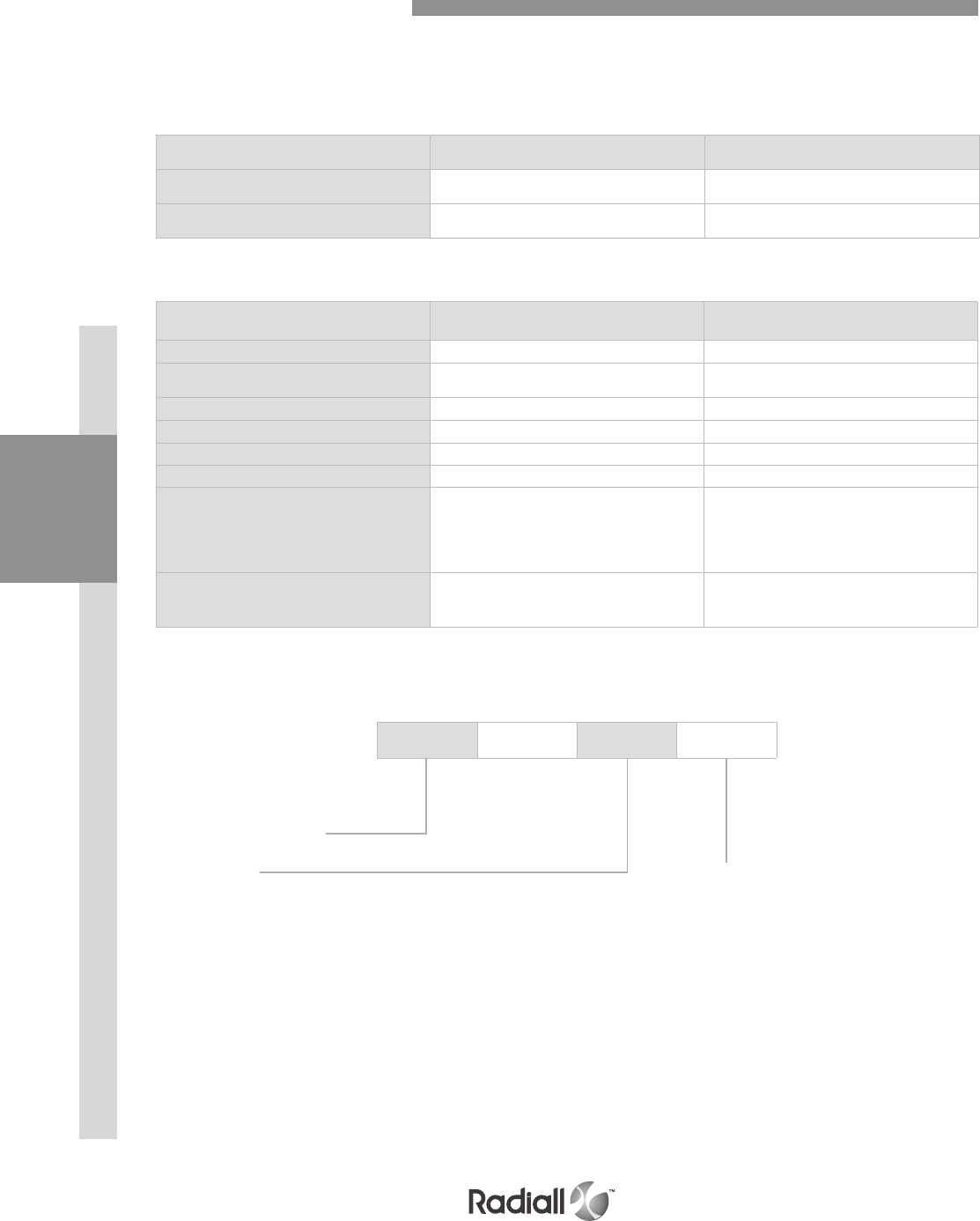
LUXCIS® CONTACT PART NUMBERING SYSTEM
F725 003 419
Cable type and diameter
118:
900 m cable
318: 1.2 mm cable with strengthening
members, tight structure
419: 1.6 to 2.2 mm cable, loose structure
519: 1.6 to 2.2 mm cable, tight structure
F725: LuxCis® series
Ferrule type
00:
PC ferrule for SingleMode fiber
03: PC ferrule for 50/125 or 62,5/125 um MultiMode fiber
04: PC ferrule for 100/40 um MultiMode fiber
05: PC ferrule for 200/230 um MultiMode fiber
50: APC ferrule for SingleMode fiber
LuxCis® Fiber Optic Contacts
DISCONNECT APPLICATIONRACK & PANEL APPLICATION CONTACTS INSERTS EPX® SERIES
1-23
Our Most Important Connection is with You.™
Go online for data sheets & assembly instructions Visit www.radiall.com and enter the part number
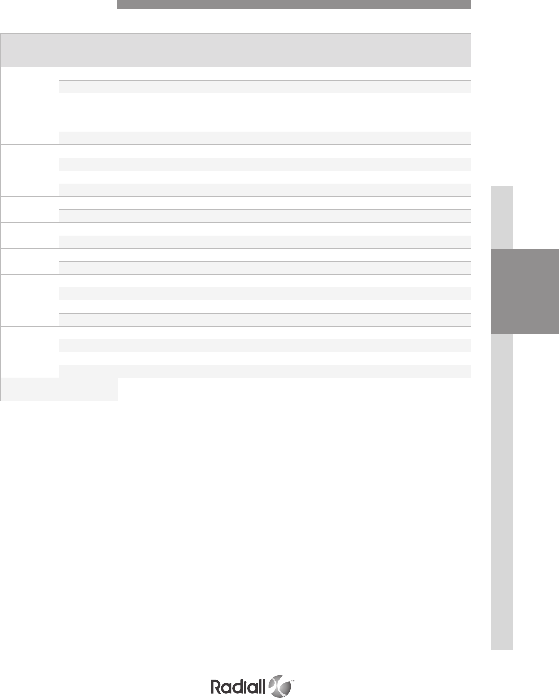
Contact
termination Contact type Size 22 Size 20 Size 16 Size 12 Size 8 Size 5
RA Pin 617205510 617222514 617242510 617259505 617291501 617289506
Socket 617305500 617322505 617342510 617359505 617391501 617389506
YA Pin 617205010 617222014 617242010 617259005 617291001 617289006
Socket 617305 617322005 617342010 617359005 617391001 617389006
ZA Pin 617205710 617222714 617242710 617259705 617291701 617289706
Socket 617305700 617322705 617342710 617359705 617391701 617389706
RB Pin 617205501 617222512 617242508 617259506 617291503 617289504
Socket 617305501 617322506 617342511 617359506 617391503 617389504
YB Pin 617205001 617222012 617242008 617259006 617291003 617289004
Socket 617305001 617322006 617342011 617359006 617391003 617389004
ZB Pin 617205701 617222712 617242708 617259706 617291703 617289704
Socket 617305701 617322706 617342711 617359706 617391703 617389704
RC Pin 617205515 617222513 617242517 617259503 617291504 617289503
Socket 617305508 617322507 617342513 617359503 617391504 617389503
YC Pin 617205015 617222013 617242017 617259003 617291004 617289003
Socket 617305008 617322007 617342013 617359003 617391004 617389003
ZC Pin 617205715 617222713 617242717 617259703 617291704 617289703
Socket 617305708 617322707 617342713 617359703 617391704 617389703
RD Pin 617205509 617222510 617242509 617259507 617291505 617289507
Socket 617305502 617322509 617342515 617359507 617391505 617389507
YD Pin 617205009 617222010 617242009 617259007 617291005 617289007
Socket 617305002 617322009 617342015 617359007 617391005 617389007
ZD Pin 617205709 617222710 617242709 617259707 617291705 617289707
Socket 617305702 617322709 617342715 617359707 617391705 617389707
Ins/ext. tool 282522
M81969/14-01
282522001
M81969/39-01
282515
M81969/14-03
282549004
M81969/14-04
282549001
M81969/28-03
282946
M81969/28-01
Signal PC tail Contacts
Selection table for straight PC tail contacts
INSERTSDISCONNECT APPLICATIONRACK & PANEL APPLICATION CONTACTS EPX® SERIES
1-24
Our Most Important Connection is with You.™
Go online for data sheets & assembly instructions Visit www.radiall.com and enter the part number
Contact size Filler plug Sealing plug
Size 22 620920 616910
Size 20 610941 616911
Size 16 620922 616912
Size 12 620923 616913
Size 8 Socket 619950 618915
Pin 619953
Size 5 Socket 617931 616914013
Pin 617930
Contact termination Contact type Part number
size 8
RA Pin 617177512
Socket 617077512
YA Pin 617177012
Socket 617077012
ZA Pin 617177712
Socket 617077712
RB Pin 617177501
Socket 617077502
YB Pin 617177001
Socket 617077002
ZB Pin 617177701
Socket 617077702
RC Pin 617177508
Socket 617077508
YC Pin 617177008
Socket 617077008
ZC Pin 617177708
Socket 617077708
RD Pin 617177513
Socket 617077513
YD Pin 617177013
Socket 617077013
ZD Pin 617177713
Socket 617077713
Ext. tool 282549001
QUADRAX SIZE 8 PC tail CONTACTS
Filler Plugs & Sealing Plugs
Selection table for straight PC tail contacts
Sealing plugs are dedicated to environmental inserts and filler plugs are dedicated to non-environmental inserts
DISCONNECT APPLICATIONRACK & PANEL APPLICATION CONTACTS INSERTS EPX® SERIES
1-25
Our Most Important Connection is with You.™
Go online for data sheets & assembly instructions Visit www.radiall.com and enter the part number
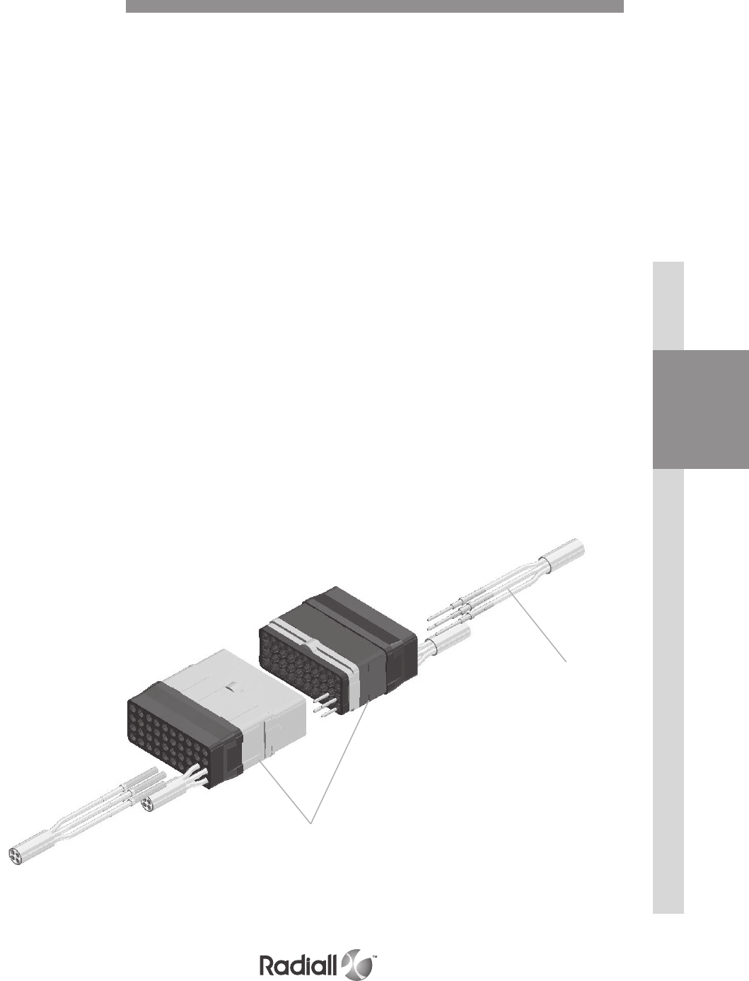
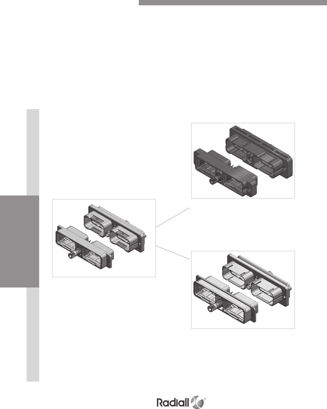
Radiall offers gigabit ethernet solutions based on standard components
These 2 solutions are perfectly suited for high speed transfers for digital audio and video signals
QUADRAX SOLUTION:
- Available with any EPXB connector
- 2 Quadrax contacts are required for 1 Gigabit link
- Quadrax inserts: 3Q3 or 10Q2
- Up to 2 Gbit/sec
HIGH DENSITY SOLUTION:
- Available with any EPXB connector
- 4 twisted pairs requires 8 #22 contacts for 1 Gbit link
- Inserts: 40 or 25Q1
- Additional size 22 contacts can be used for ground continuity
- EMI backshell (recommended by Radiall)
- Up to 1 Gbit/sec
- Short strip dimensions are required to get minimum impedance disturbance.
Radiall solution combines short strip and easy maintenance availability.
For further information, please contact Radiall
High density solution
Detailed view of inserts including contacts for gigabit ethernet link
Size 22 contacts
Inserts
Contacts for GBE Links
INSERTSDISCONNECT APPLICATIONRACK & PANEL APPLICATION DISCONNECT APPLICATION CONTACTS EPX® SERIES
1-26
Our Most Important Connection is with You.™
Go online for data sheets & assembly instructions Visit www.radiall.com and enter the part number
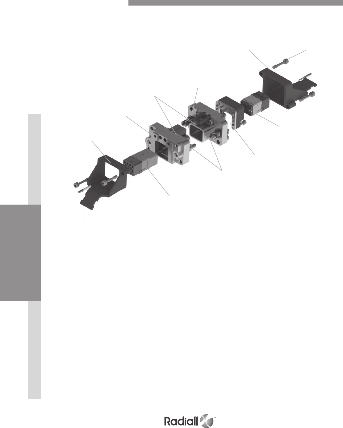
Insert
Fiber optic
contact
45° Strain
relief
Receptacle
shell
Polarization
keys
Straight
strain relief
Screws are captive
mounted
Plug shell
Quarter-turn
locking device
Ground block
Sleeve holder
Detailed view of receptacle and plug with accessories for the EPXA1 connector
EPXA Product Overview
DISCONNECT APPLICATIONRACK & PANEL APPLICATION INSERTSDISCONNECT APPLICATION CONTACTS EPX® SERIES
1-27
Our Most Important Connection is with You.™
Go online for data sheets & assembly instructions Visit www.radiall.com and enter the part number
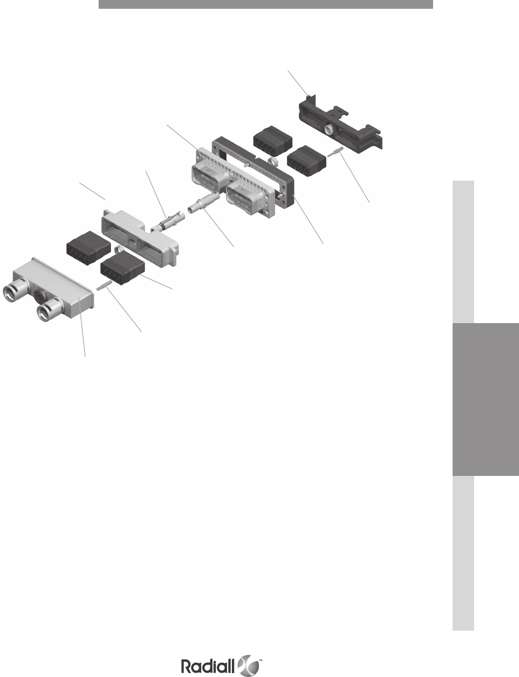
EMI backshell
Insert
Straight
strain relief
Socket
contact
Plug shell
Polarization keys
Receptacle shell
Pin contact
Quarter-turn
locking device
Ground block
Detailed view of receptacle and plug with accessories for the EPXB1 connector
EPXB1 Product Overview
INSERTSDISCONNECT APPLICATIONRACK & PANEL APPLICATION DISCONNECT APPLICATION CONTACTS EPX® SERIES
1-28
Our Most Important Connection is with You.™
Go online for data sheets & assembly instructions Visit www.radiall.com and enter the part number
NOTES:
(1) Recommended locking torque: 1.6Nm (14.16 in-lbs) for metallic shell and 1.1Nm (9.73 in-lbs) max for composite shell
(2) Self-locking mounting holes are designed for rear panel mounting
(3) Please see page 1-33 on how to use the polarization device
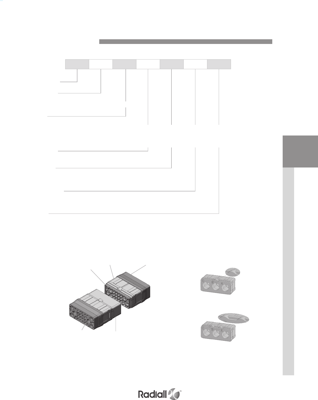
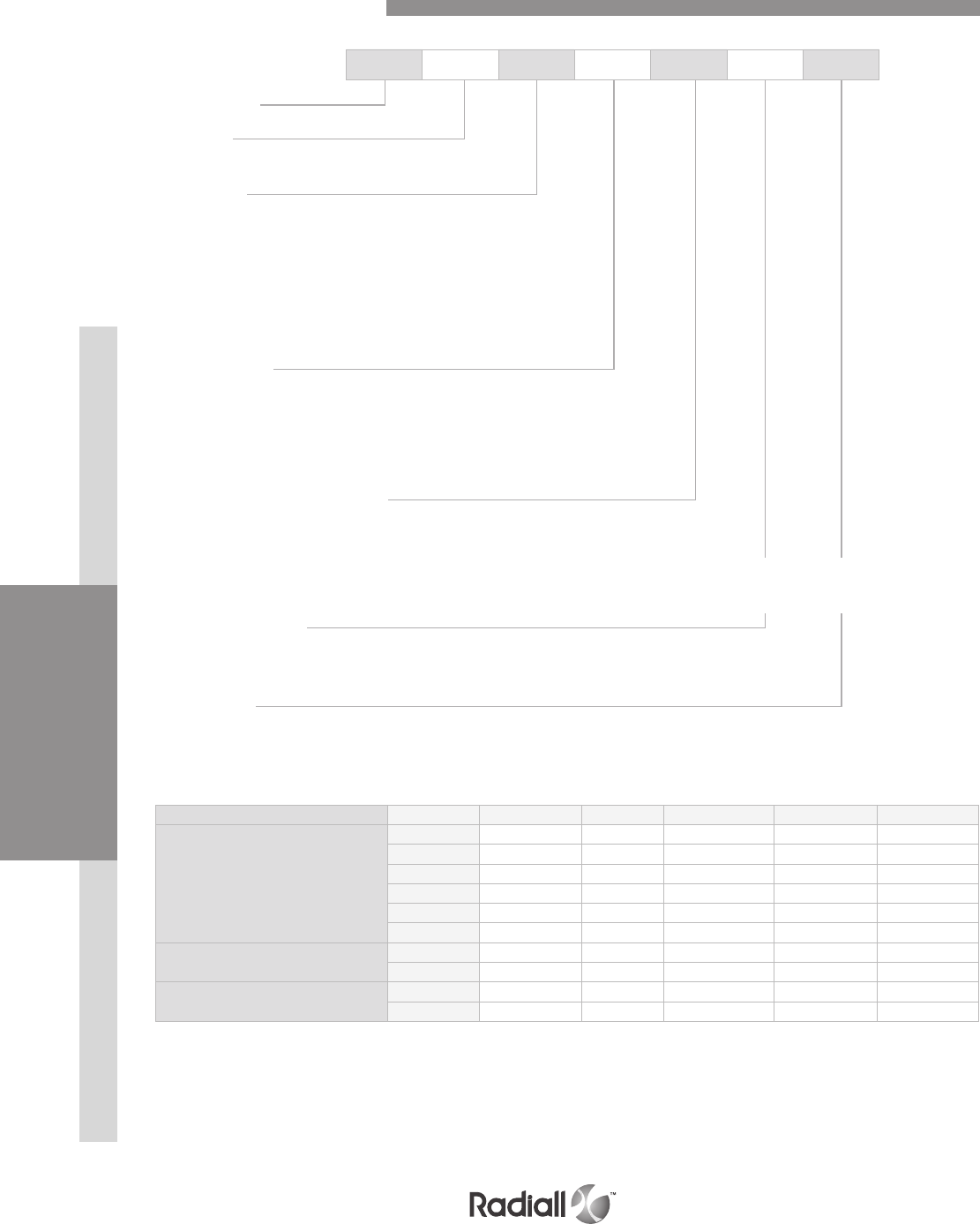
EPX B1 P B 0 4 M
Series prefix
Shell size
A1: Single small cavity shell
B1: Single large cavity shell
Shell style
P: Plug
R: Receptacle
W: Plug with ground block
Z: Receptacle with ground block and ground spring fingers
Shell mounting option(1)
B: Plug without mounting holes
M: Receptacle with 2 mounting holes 6-32 UNC for rear panel(2)
Locking device
0: Quarter-turn fastener
Polarization code(3)
4: Shell delivered with polarizing hardware unassembled
5: Shell delivered with no polarizing hardware
Shell plating
M: Nickel-plated composite for EPXB1
K: Nickel-plated aluminium for EPXB1 (mateable with version M composite shell)
N: Nickel-plated aluminium for EPXA
How to Order EPXA & EPXB1 Shell

DISCONNECT APPLICATIONRACK & PANEL APPLICATION INSERTSDISCONNECT APPLICATION CONTACTS EPX® SERIES
1-29
Our Most Important Connection is with You.™
Go online for data sheets & assembly instructions Visit www.radiall.com and enter the part number
Assembly kit is delivered fully assembled including shell with insert mounted, with or without contacts
according to the selection.
Tips to help you in your selection:
- You are free to use either pin or socket inserts in EPXA & EPXB1 plug or receptacles.
- Crimp contacts can be delivered with a kit, check which contacts would be included on page 1-12.
- If PC tail are selected then all cavities including signal, power and quadrax are populated. Size 5 coax
cavities are not populated.
- If PC tail contacts are needed, remember that they are available as pin straight PC tail contacts in
receptacles only.
EPX B1 R 4 M E M YA
SHELL SELECTION PART
INSERT SELECTION PART
Series prefix
Shell size
A1: Single small cavity shell
B1: Single large cavity shell
Shell style
P: Plug
R: Receptacle
W: Plug with ground block
Z: Receptacle with ground block and ground fingers
Polarization code
4: Shell delivered with polarizing hardware unassembled
5: Shell delivered with no polarizing hardware
Shell plating
M: Nickel-plated composite for EPXB1
K: Nickel-plated aluminium for EPXB1 (mateable with version M composite shell)
N: Nickel-plated aluminium for EPXA
How to Order EPXA & EPXB1 Assembly Kit
These contacts are delivered uninstalled
Refer to page 1-30 to select PC tail contacts for receptacle
Insert class
E: Environmental
N: Non-environmental (no rear grommet, no interfacial seal)
H: Non-environmental insert with a rear grommet, available for pin insert only (recommended for crimp contact)
T: Non-environmental insert with an interfacial seal, available for pin insert only (recommended for PC tail contact)
Insert code
Refer to page 1-12 to select insert code
Contacts termination
XS: Socket insert without contacts
XP: Pin insert without contacts
SS: Socket insert with crimp contacts
SP: Pin insert with crimp contacts
YA: Gold PC tail contacts length A
ZA: Tin-lead PC tail contacts length A
RA: Pure tin (RoHS) PC tail contacts length A

INSERTSDISCONNECT APPLICATIONRACK & PANEL APPLICATION DISCONNECT APPLICATION CONTACTS EPX® SERIES
1-30
Our Most Important Connection is with You.™
Go online for data sheets & assembly instructions Visit www.radiall.com and enter the part number
H
E
EPXB1 RECEPTACLES (aluminium and composite shell version)
NOTE:
(1) These PC tail lengths are not compatible with EPXBE and EPXBH inserts
Contacts Termination for EPXB1
Straight PC Tail contact termination
Min Length E
mm (inch)
Min Length H
mm (inch) Gold Tin-lead Pure tin (RoHS)
16.20 (0.637) (1) /YA ZA RA
19.40 (0.763) (1) /YB ZB RB
21.25 (0.836) (1) /YC ZC RC
25.20 (0.992) 5.40 (0.212) YD ZD RD
DISCONNECT APPLICATIONRACK & PANEL APPLICATION INSERTSDISCONNECT APPLICATION CONTACTS EPX® SERIES
1-31
Our Most Important Connection is with You.™
Go online for data sheets & assembly instructions Visit www.radiall.com and enter the part number
Receptacle Plug
WITHOUT GROUND BLOCK SINGLE PANEL CUT OUT (2)
NOTES:
(1) Maximum dimension for insert with grommets
For inserts without grommets maximum dimensions will be for receptacle 25.55mm (1.006in) and for the plug 23.52mm (0.926in)
(2) Rear mounting side view with key post oriented to the upper side
Receptacle Plug
WITH GROUND BLOCK MULTIPLE PANEL CUT OUT (2)
EPXA Shell Dimensions
INSERTSDISCONNECT APPLICATIONRACK & PANEL APPLICATION DISCONNECT APPLICATION CONTACTS EPX® SERIES
1-32
Our Most Important Connection is with You.™
Go online for data sheets & assembly instructions Visit www.radiall.com and enter the part number
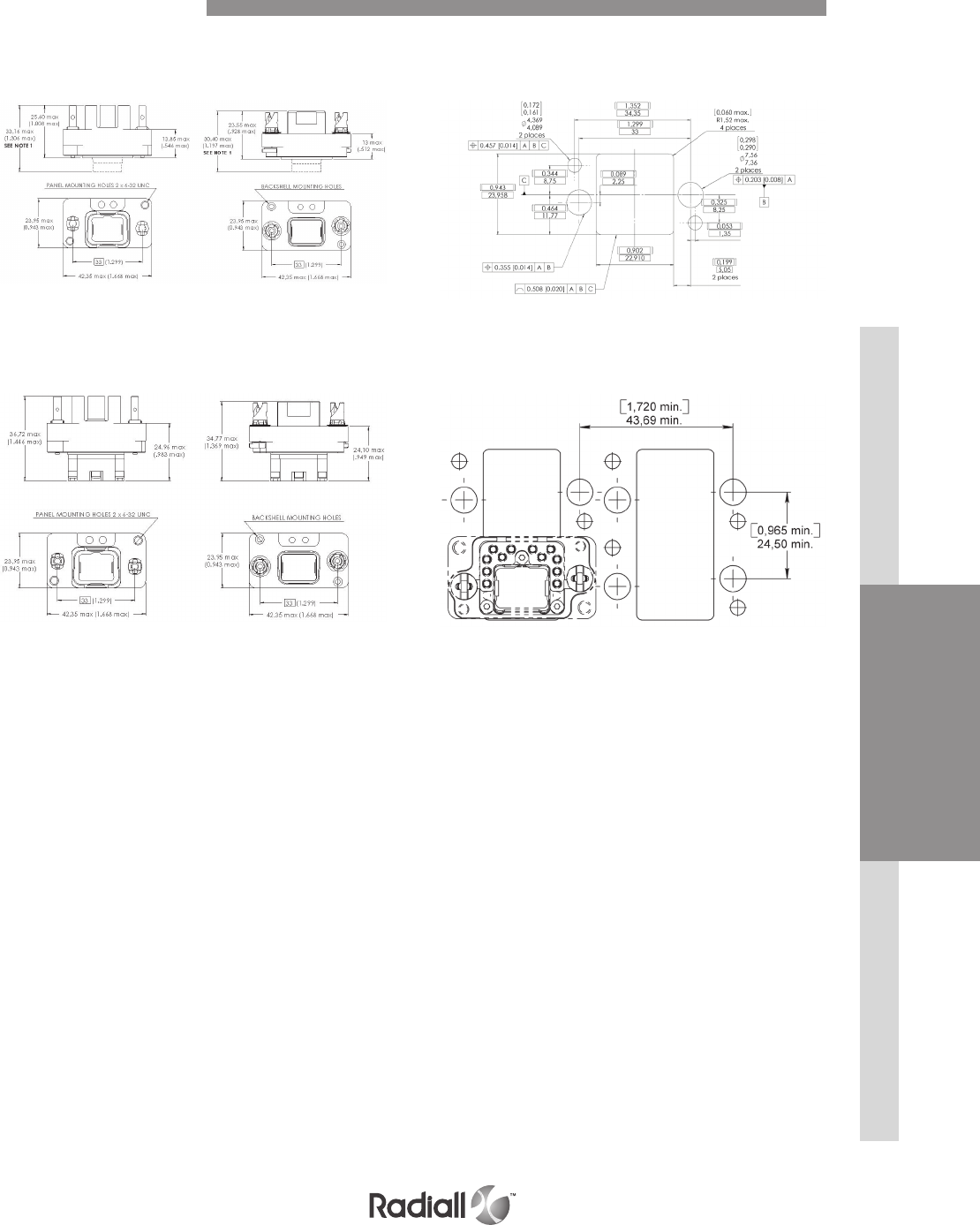
Receptacle Plug
WITHOUT GROUND BLOCK SINGLE PANEL CUT OUT (2)
Receptacle Plug
WITH GROUND BLOCK MULTIPLE PANEL CUT OUT (2)
NOTES:
(1) Maximum dimension for insert with grommets. For inserts without grommets: Insert is flush to the shell. Maximum dimension for the receptacle
is 25.55 mm(1.006 in) and for the plug is 23.52 mm(0.926 in).For inserts with optical contacts : the maximum dimension for the receptacle is 38.70
mm(1.524 in) and the plug is 36.00 mm (1.418 in)
(2) Rear mounting side view with key post oriented to the upper side
EPXB1 Shell Dimensions

DISCONNECT APPLICATIONRACK & PANEL APPLICATION INSERTSDISCONNECT APPLICATION CONTACTS EPX® SERIES
1-33
Our Most Important Connection is with You.™
Go online for data sheets & assembly instructions Visit www.radiall.com and enter the part number
EASY READING OF POLARIZATION CODE
Plug Receptacle
EPXA
EPXB1
Coding device
View A & B View C & D View A & D View C & B
Caution: Read the polarization code from left to right, the same way the part number marking
can be read on the connector
There are 16 possible codings:
Key position 1 A A A A B B B B C C C C D D D D
Key position 2 A B C D A B C D A B C D A B C D
Polarization Code
11
22
INSERTSDISCONNECT APPLICATIONRACK & PANEL APPLICATION DISCONNECT APPLICATION CONTACTS EPX® SERIES
1-34
Our Most Important Connection is with You.™
Go online for data sheets & assembly instructions Visit www.radiall.com and enter the part number
Part number Description Assembly tool Assembly torque
EPXA EPXB1
617980032 -Polarization kit for
plug connector
282666002 0.8 Nm
(7 In-Ibs)
617980033 -Polarization kit for
receptacle connector
-617980030 Polarization post
N/A
N/A
-617980031 Polarization key
617954006 617954008 Dust cap for plug shell
(pink color)
617954007 617954009 Dust cap for receptacle shell
(pink color)
617954044 617954034 ESD dust cap for plug shell
(black color)
617954045 617954028 ESD dust cap for receptacle
shell (black color)
617929033
Sealing inserts for fly away
applications: mateable
with pin insert
N/A
617929023
617929032
Sealing inserts for fly away
applications: mateable
with socket insert
617929022
SPARE PARTS & DUST CAPS
EPXA & EPXB1 Accessories
DISCONNECT APPLICATIONRACK & PANEL APPLICATION INSERTSDISCONNECT APPLICATION CONTACTS EPX® SERIES
1-35
Our Most Important Connection is with You.™
Go online for data sheets & assembly instructions Visit www.radiall.com and enter the part number
Part number Description Assembly
tool
Assembly
torque
EPXA EPXB1
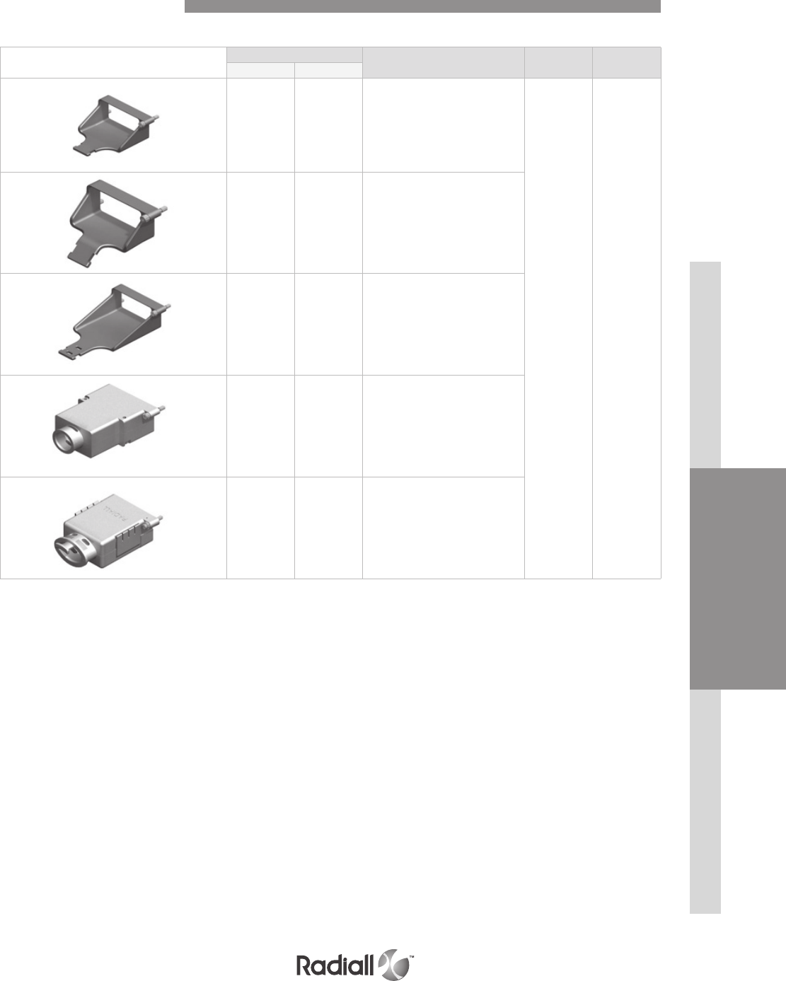
617921030 617921029 Straight strain relief (composite)
282666002 0.8 Nm
(7 In-Ibs)
617921032 617921031 45° strain relief (composite)
-617921035 Strain relief for fiber optic
(anodized aluminium)
-617924016 Straight EMI backshell
(Nickel-plated aluminium)
-617928002 Straight EMI backshell
(Nickel-plated composite)
NOTE:
For mounting instructions, please contact Radiall
STRAIN RELIEF AND EMI BACKSHELLS
EPXA & EPXB1 Accessories
INSERTSDISCONNECT APPLICATIONRACK & PANEL APPLICATION DISCONNECT APPLICATION CONTACTS EPX® SERIES
1-36
Our Most Important Connection is with You.™
Go online for data sheets & assembly instructions Visit www.radiall.com and enter the part number
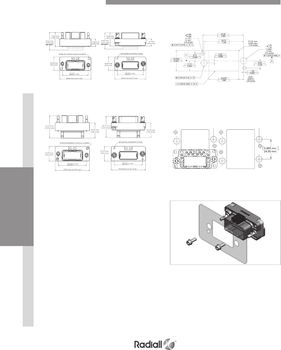
EPXB2 Disconnect Connectors
When less is more.
Radiall EPXB2 disconnect connectors have been widely used in aerospace industry for more than 10
years. As a worldwide leader in cable to cable and PCB to cable connections, Radiall is committed to
constantly innovating to meet the demands of the industry with the most effective and reliable solutions.
Demand for weight saving connection solution is now growing more and more.
Radiall is proud to introduce:
- EPXB2 class M (Nickel plated composite)
- EPXB2 class J (Weight optimized aluminium)
Two proven and available alternatives when you are facing weight issues in cable to cable
and PCB to cable connections.
EPXB2 class M
Performances:
- Weight saving compared to class N EPXB2 : -15%
- T° range: -65°C / +125°C
EPXB2 class J
Performances:
- Weight saving compared to class N EPXB2: -15%
- Cost effective solution
- T° range: -65°C / +175°C
EPXB2 class N
Performances :
- T° range -65°C / +175°C
DISCONNECT APPLICATIONRACK & PANEL APPLICATION INSERTSDISCONNECT APPLICATION CONTACTS EPX® SERIES
1-37
Our Most Important Connection is with You.™
Go online for data sheets & assembly instructions Visit www.radiall.com and enter the part number
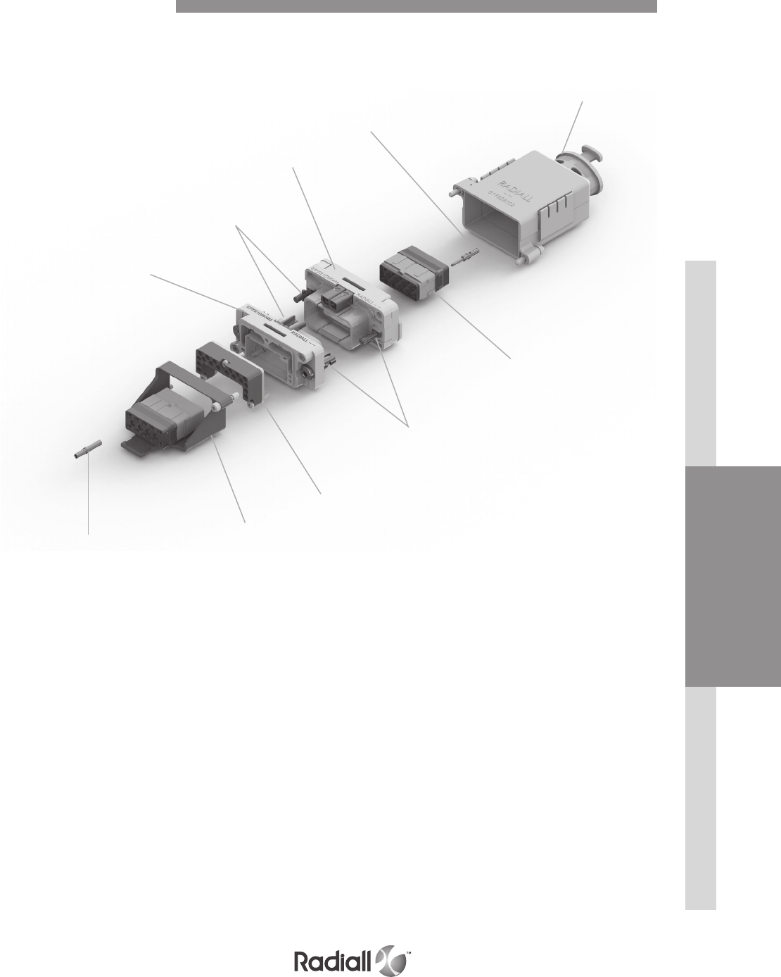
Socket
contact
EMI backshell
Inserts
Jacknut locking
device
Ground
block
Pin
contact
Plug
shell
Jackscrew
locking device
Receptacle
shell
Strain relief
Detailed view of receptacle and plug with accessories for the EPXB2 disconnect connector.
EPXB2 Product Overview
INSERTSDISCONNECT APPLICATIONRACK & PANEL APPLICATION DISCONNECT APPLICATION CONTACTS EPX® SERIES
1-38
Our Most Important Connection is with You.™
Go online for data sheets & assembly instructions Visit www.radiall.com and enter the part number
Series prefix
Shell size
B2: Two cavity shell
Shell style
For option compatibility, see the table below
L: Receptacle with flange and ground fingers
H: Receptacle with ground fingers
Z: Receptacle with ground block and ground fingers
R: Receptacle without ground fingers
P: Plug
W: Plug with ground block
Shell mounting
A: Panel rear mounted connector with 4 x 6-32 mounting holes
B: No mounting holes
D: Connector with 2 x Ø3.10 mm thru holes
F: Panel rear mounted connector with 2 x 6-32 mounting holes
L: Panel rear mounted connector with 2 x 4-40 mounting holes
Locking & polarization device (1)
1: Jackscrew
2: Jacknut
3: Without locking device
4: Pin centering guide for plug shell for LRU
(Line Replaceable Unit)
application only (2)
5: Socket centering guide for receptacle shell for LRU
(Line Replaceable Unit)
application only (2)
Polarization code (3)
2: Polarizing device A to F delivered unassembled
3: Polarizing device N to Z delivered unassembled
Shell plating
N: Nickel-plated aluminium
M: Nickel-plated composite
J: Nickel-plated weight optimized aluminium
NOTES:
(1) Jackscrew/Jacknut can be mounted on either plug or receptacle shell. However, the standard options are:
- Jackscrew for plug shells
- Jacknut for receptacle shells
(2) Pin/Socket centering guides can be mounted on either plug or receptacle shells. However, the standard options are:
- Pin centering guide for plug shells
- Socket centering guide for receptacle shells
(3) Please see page 1-44 for how to use the the polarization coding
EPX B2 H L 2 2 N
AVAILABLE SHELL MOUNTING
How to Order EPXB2 Shell
Shell style A (4 x 6.32 UNC) B (no holes) D (2 x Ø3.10mm) F (2 x 6.32 UNC) L (2 x 4.40 UNC)
Class N (aluminium)
L √ √ √
H √ √ √ √
Z √ √
R √
P √ √ √
W √ √
Class J (weight optimized aluminium) H √
P √
Class M (composite) L √ √
P √ √ √

DISCONNECT APPLICATIONRACK & PANEL APPLICATION INSERTSDISCONNECT APPLICATION CONTACTS EPX® SERIES
1-39
Our Most Important Connection is with You.™
Go online for data sheets & assembly instructions Visit www.radiall.com and enter the part number
Assembly kits are delivered fully assembled including shell with inserts mounted, with or without
contacts according to the selection. When selecting your insert codes, do not forget to place them in the
order you want them assembled. Locking and polarizing devices are delivered uninstalled.
Tips to help you in your selection:
- You are free to use either pin or socket inserts in EPXB plug or receptacle.
- Crimp contacts can be delivered with a kit, check which contacts will be included on page 1-12.
- PC tail contacts can also delivered with a kit. Remember that only straigh tpin PC tail
contacts are available, and in receptacle only.
- If PC tail contacts are selected then all cavities including signal, power and
quadrax are populated. Size 5 coax cavities are not populated.
All connector inserts will use the same insert class and the same contact termination.
EPX B2 H B 2 N N BC ZB
INSERTS SELECTION PART
SHELL SELECTION PART
How to Order EPXB2 Assembly Kit
These contacts are delivered uninstalled
Refer to pages 1- 40 to select PC tail contacts for receptacle
Series prefix
Shell size
B2: Two cavity shell
Shell style
For option compatibly, see table on page 1-36
L: Receptacle with flange and ground fingers
H: Receptacle with ground fingers
Z: Receptacle with ground block and ground fingers
R: Receptacle without ground fingers
P: Plug
W: Plug with ground block
Shell mounting
A: Rear panel mounted connector with 4x 6-32 mounting holes
B: No mounting holes
D: Connector with 2 x Ø3.10 mm thru holes
F: Rear panel mounted connector with 2 x 6-32 mounting holes
L: Rear panel mounted connector with 2 x 4-40 mounting holes
Polarization
1: Jackscrew polarizing device A to F
2: Jacknut polarizing device A to F
3: Without locking device
4: Pin centering guide for plug shell for LRU application only, polarizing device A to F
5: Socket centering guide for receptacle shell for LRU application only, polarizing device A to F
6: Jackscrew polarizing device N to Z
7: Jacknut polarizing device N to Z
8: Pin centering guide for plug shell for LRU application only, polarizing device N to Z
9: Socket centering guide for receptacle shell for LRU application only, polarizing device N to Z
Shell plating
N: Nickel-plated aluminium
M: Nickel-plated composite
J: Nickel-plated weight optimized aluminium
Insert class
E: Environmental
N: Non-environmental
H: Non-environmental insert with a rear grommet, available for pin insert only (recommended for crimp contact)
T: Non-environmental insert with interfacial seal, available for pin insert only (recommended for PC tail contact)
Insert code
Refer to page 1-12 to select code insert
Contacts termination
XS: Socket insert without contacts
XP: Pin insert without contacts
SS: Socket insert with crimp contacts
SP: Pin insert with crimp contacts
YA: Gold PC tail contacts length A
ZA: Tin-lead PC tail contacts length A
RA: Pure tin (RoHS) PC tail contacts length A
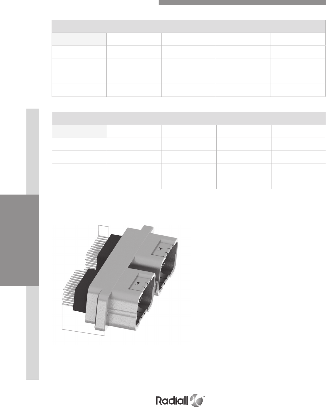
INSERTSDISCONNECT APPLICATIONRACK & PANEL APPLICATION DISCONNECT APPLICATION CONTACTS EPX® SERIES
1-40
Our Most Important Connection is with You.™
Go online for data sheets & assembly instructions Visit www.radiall.com and enter the part number
EPXB2 COMPOSITE SHELL
Straight PC Tail contact termination
Min Length E
mm (inch)
Min Length H
mm (inch) Gold Tin-lead Pure tin (RoHS)
14.20 (0.559) (1) /YA ZA RA
17.35 (0.683) (1) /YB ZB RB
19.20 (0.755) (1) /YC ZC RC
23.10 (0.909) 5.40 (0.212) YD ZD RD
EPXB2 WEIGHT OPTIMIZED ALUMINIUM AND ALUMINIUM SHELL
NOTE:
(1) These PC tail lengths are not compatible with EPXBE and EPXBH inserts
Contacts Termination for Receptacles
H
E
Straight PC Tail contact termination
Min Length E
mm (inch)
Min Length H
mm (inch) Gold Tin-lead Pure tin (RoHS)
14.55 (0.572) (1) /YA ZA RA
17.75 (0.698) (1) /YB ZB RB
19.55 (0.769) (1) /YC ZC RC
23.50 (0.925) 5.40 (0.212) YD ZD RD
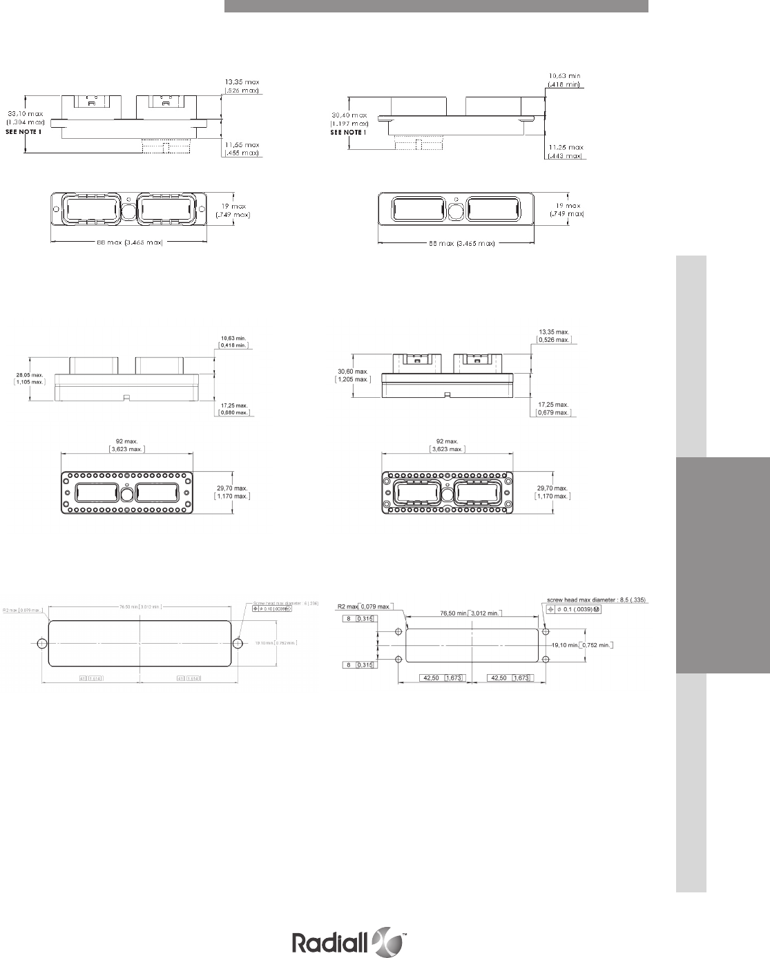
DISCONNECT APPLICATIONRACK & PANEL APPLICATION INSERTSDISCONNECT APPLICATION CONTACTS EPX® SERIES
1-41
Our Most Important Connection is with You.™
Go online for data sheets & assembly instructions Visit www.radiall.com and enter the part number
NOTES:
For inserts with grommets : maximum dimension is shown in the diagram
(1) For inserts without grommets: Insert is flush to the shell. Maximum dimension for the receptacle is 25.55 mm(1.006 in) and for the plug is 23.52
mm(0.926 in)
For inserts with optical contacts : the maximum dimension for the receptacle is 38.70 mm(1.524 in) and for the plug is 36.00 mm (1.418 in)
EPXB2 Metallic Shell Dimensions
Receptacle Plug
WITHOUT GROUND BLOCK Class N & J
Receptacle Plug
WITH GROUND BLOCK Class N
PANEL CUT OUT Class N & J
Shell mounting code D, F and L Shell mounting code A
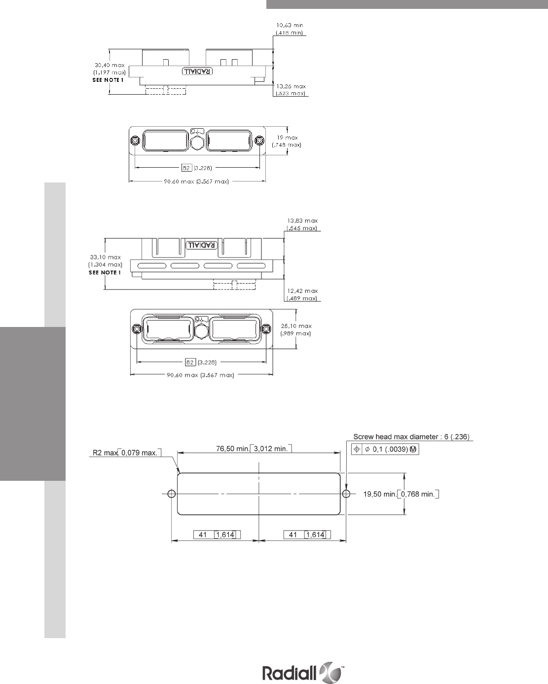
INSERTSDISCONNECT APPLICATIONRACK & PANEL APPLICATION DISCONNECT APPLICATION CONTACTS EPX® SERIES
1-42
Our Most Important Connection is with You.™
Go online for data sheets & assembly instructions Visit www.radiall.com and enter the part number
PLUG
NOTE:
(1) For inserts with grommets (EPXBE and EPXBH) : maximum dimension is shown in the diagram
For inserts without grommets (EPXBN) : Insert is flush to the shell. Maximum dimension for the receptacle is 25.55 mm(1.006 in) and
for the plug is 23.52 mm(0.926 in)
For inserts with optical contacts : the maximum dimension for the receptacle is 38.70 mm(1.524 in) and the plug is 36.00 mm (1.418 in)
RECEPTACLE
EPXB2 Composite Shell Dimensions
PANEL CUT OUT
Shell mounting code D and L
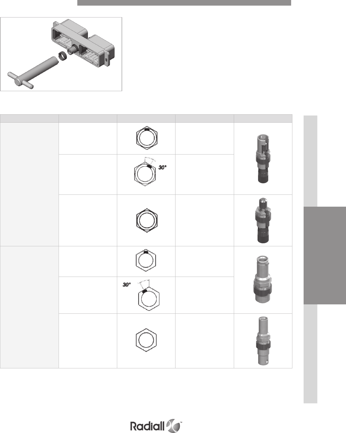
DISCONNECT APPLICATIONRACK & PANEL APPLICATION INSERTSDISCONNECT APPLICATION CONTACTS EPX® SERIES
1-43
Our Most Important Connection is with You.™
Go online for data sheets & assembly instructions Visit www.radiall.com and enter the part number
As a standard, jackscrews
shall be installed in plugs and
jacknuts in receptacle shells.
The polarizing device must be locked
by the operator at 1.2 Nm (10.62
Lb-In.) for the metallic shell and
0.8Nm (7.08 Lb-In.) for composite
shell. LOCTITE™ 272 resin shall
be used to assemble them.
The nut can be fixed with your automatic screwdriver and the tool bit we provide (PN 282664)
EPXB2 Polarization Code
Designation Polarization code Coding device key Part number
Jackscrew
From A to F 617980012
From N to Z
30° offset compared to
the key of jackscrew P/N
617980012
617980013
Universal 617980023
Jacknut
From A to F 617980029
From N to Z
30° offset compared to the
key of jacknut 617980029
617980028
Universal 617980022
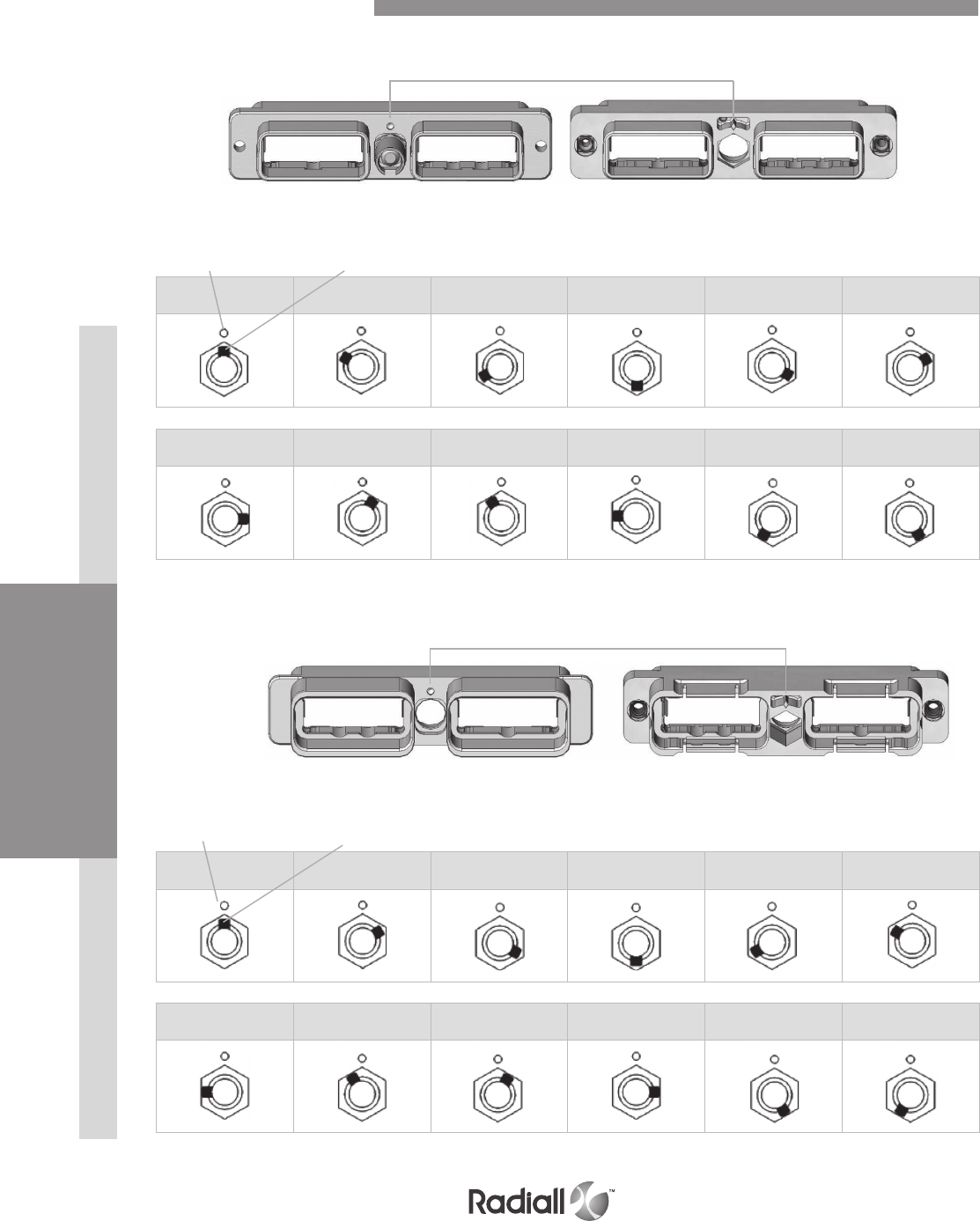
INSERTSDISCONNECT APPLICATIONRACK & PANEL APPLICATION DISCONNECT APPLICATION CONTACTS EPX® SERIES
1-44
Our Most Important Connection is with You.™
Go online for data sheets & assembly instructions Visit www.radiall.com and enter the part number
PLUG SHELL
Shell reference mark
Aluminium shell Composite shell
EPXB2 Polarization Code
Shell reference mark Coding device key
N R W X Y Z
A B C D E F
RECEPTACLE SHELL
Shell reference mark Coding device key
Shell reference mark
Aluminium shell Composite shell
N R W X Y Z
A B C D E F
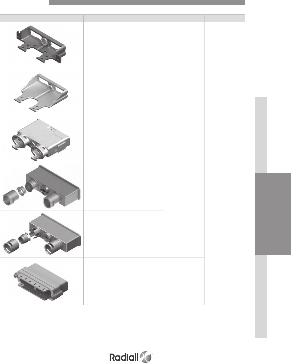
DISCONNECT APPLICATIONRACK & PANEL APPLICATION INSERTSDISCONNECT APPLICATION CONTACTS EPX® SERIES
1-45
Our Most Important Connection is with You.™
Go online for data sheets & assembly instructions Visit www.radiall.com and enter the part number
Part number Description Assembly tool (2) Assembly torque
617922007 Straight strain
relief (composite)
282664
or
282665
0.8 Nm
(7.08 in-lbs)
617922014
Straight strain relief
for fiber optic cable
(anodized aluminium)
1.2 Nm
(10.62 in-lbs)
617928100
Straight EMI backshell
(nickel-plated
composite)
Allen wrench
1/4 inch
617925052
EMI backshell
for braid shield
termination
(nickel-plated
aluminium)
282664
or
282665
617925054
EMI backshell
for screened twisted
pair cables
(nickel-plated
aluminium)
617925056
Backshell for large
sized wire harnesses
(nickel-plated
aluminium) (1)
282664
or
282665
and Allen wrench
NOTE:
(1) Not compatible with jackscrew
(2) For more details, refer to page 1-47
EPXB2 Accessories
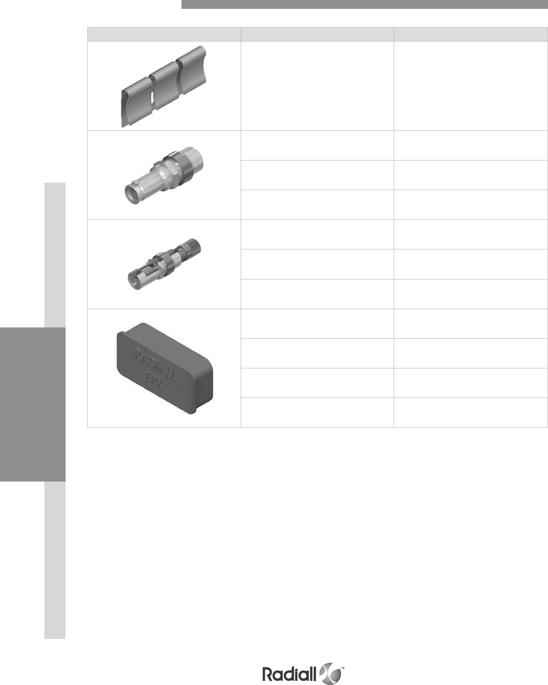
INSERTSDISCONNECT APPLICATIONRACK & PANEL APPLICATION DISCONNECT APPLICATION CONTACTS EPX® SERIES
1-46
Our Most Important Connection is with You.™
Go online for data sheets & assembly instructions Visit www.radiall.com and enter the part number
Part number Description
617954101 Grounding spring
(for EPXB2 aluminium only)
617980029 Jacknut – A/B/C/D/E/F
617980028 Jacknut – N/R/W/X/Y/Z
617980022 Universal jacknut
617980012 Jackscrew – A/B/C/D/E/F
617980013 Jackscrew – N/R/W/X/Y/Z
617980023 Universal jackscrew
617954002 Dust cap for plug shell
(pink color)
617954003 Dust cap for receptacle shell
(pink color)
617954004 ESD dust cap plug shell
(black color)
617954005 ESD dust cap receptacle shell
(black color)
EPXB2 Spare Parts
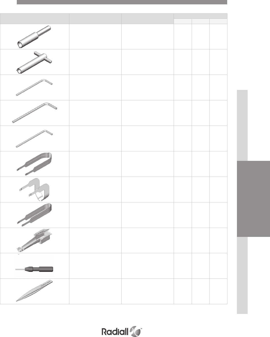
DISCONNECT APPLICATIONRACK & PANEL APPLICATION INSERTSDISCONNECT APPLICATION CONTACTS EPX® SERIES
1-47
Our Most Important Connection is with You.™
Go online for data sheets & assembly instructions Visit www.radiall.com and enter the part number
Part number Description To be used with
EPXA EPXB1 EPXB2
282664
1/4 inch hex. screwdriver bit to
affix the nut of the jackscrew
or the jacknut to the EPXB2
accessories
X
282665
Spigot wrench to affix
the nut of the jackscrew or
the jacknut to the EPXB2
accessories
X
282666 Allen wrench for 1/4 turn
fasterner (3/32 inch) X X
282666002 Allen wrench for rear
accessories (5/64 inch) X
282666001 Allen wrench for jackscrew
(9/64 inch) X
282521002 Insert extraction tool X X
282521004 Right angle insert extraction
tool X X
282521005 Insert extraction tool X
617954020 Plastic box to protect wired
inserts during handling XXX
F780855000 Hexagonal key 2mm (5/64inch)
Flats for sleeve holder removal X X
282668001 Tweezers to change polarizing
posts and keys X
Tools
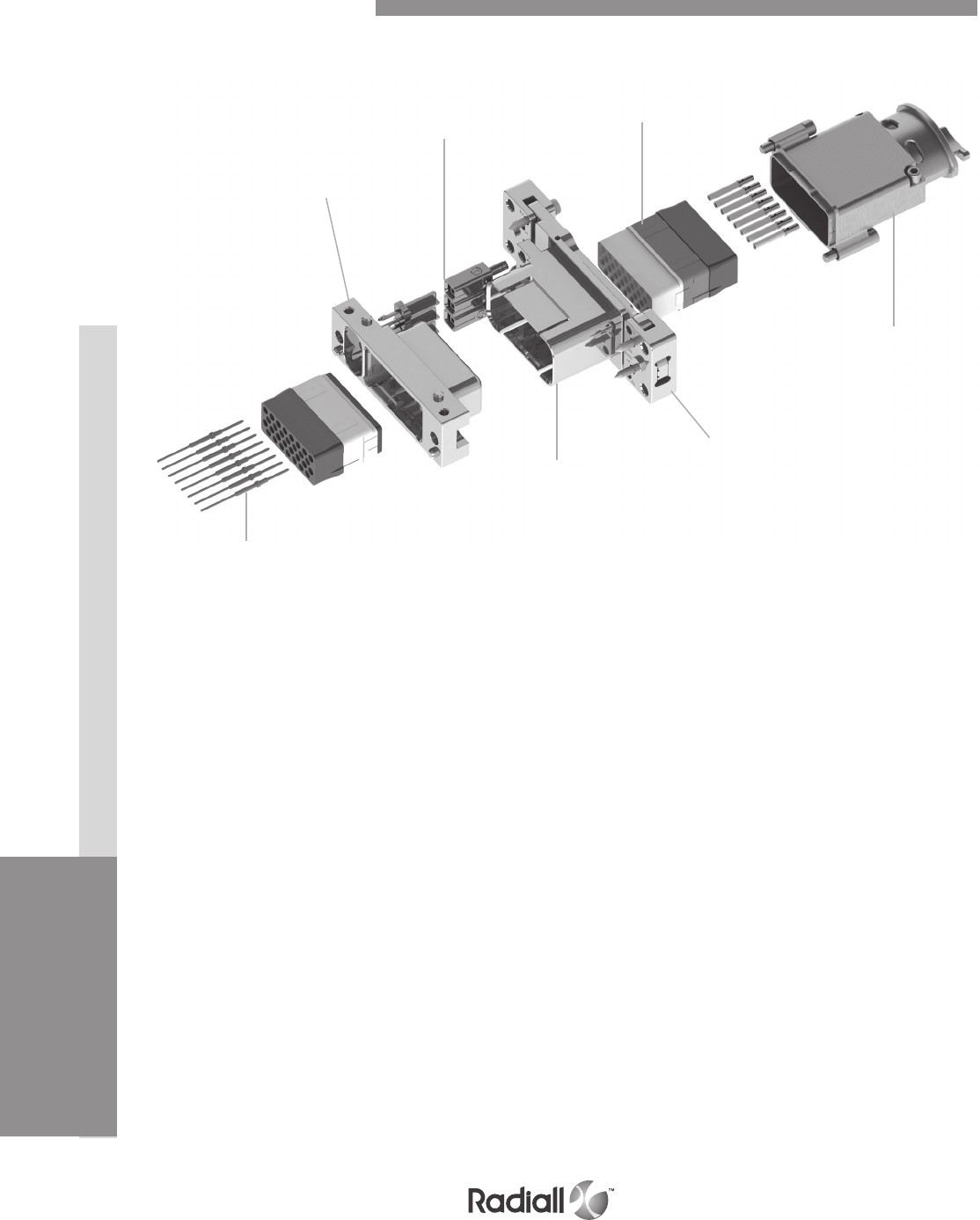
INSERTSDISCONNECT APPLICATIONRACK & PANEL APPLICATION CONTACTS EPX® SERIES
1-48 Go online for data sheets & assembly instructions Visit www.radiall.com and enter the part number
Our Most Important Connection is with You.™
EMI backshell
Plug shell
Polarization keys Inserts
Receptacle
shell
Right angle or straight
PC tail contacts
Fixed or floating
device
EPXB1 Product Overview
Detailed view of receptacle and plug with accessories for the EPXB1 rack and panel connector.
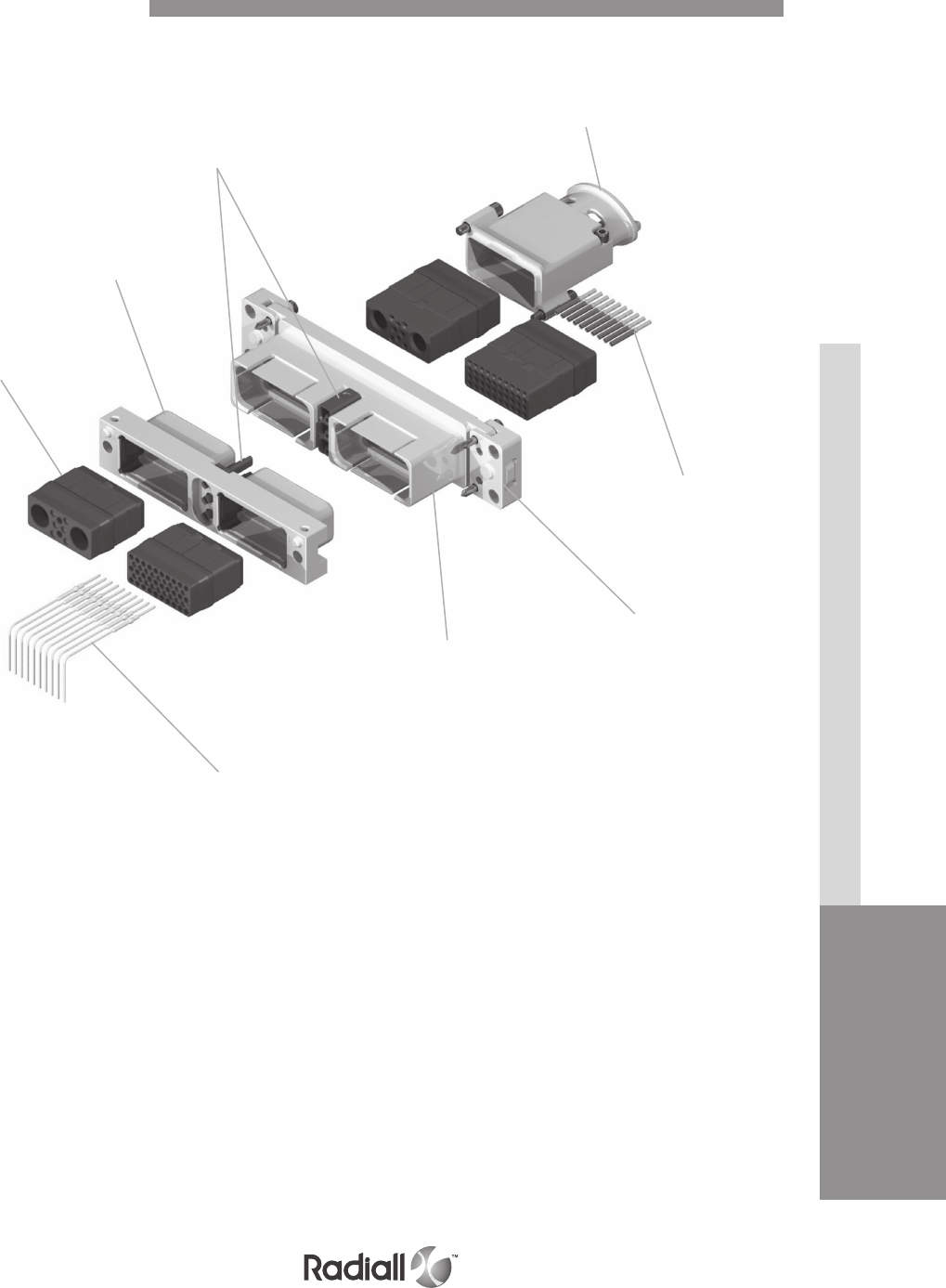
DISCONNECT APPLICATIONRACK & PANEL APPLICATION CONTACTS INSERTS EPX® SERIES
1-49
Go online for data sheets & assembly instructions Visit www.radiall.com and enter the part number
Our Most Important Connection is with You.™
Detailed view of receptacle and plug with accessories for the EPXB2 rack and panel connector.
EMI backshell
Crimp
contacts
Plug shell
Polarization keys
Inserts
Receptacle
shell
Right angle or straight
PC tail contacts
Fixed or floating
device
EPXB2 Product Overview

INSERTSDISCONNECT APPLICATIONRACK & PANEL APPLICATION CONTACTS EPX® SERIES
1-50 Go online for data sheets & assembly instructions Visit www.radiall.com and enter the part number
Our Most Important Connection is with You.™
EMI backshell
Strain relief
Crimp
contacts
Fixed or floating
device
Plug shell
Right angle or straight
PC tail contacts
Receptacle shell
Polarization
keys
Inserts
Detailed view of receptacle and plug with accessories for the EPXB3 rack and panel connector
EPXB3 Product Overview

DISCONNECT APPLICATIONRACK & PANEL APPLICATION CONTACTS INSERTS EPX® SERIES
1-51
Go online for data sheets & assembly instructions Visit www.radiall.com and enter the part number
Our Most Important Connection is with You.™
Strain relief
Crimp
contacts
Fix mounting
Plug shell
Inserts
Polarization
keys
Receptacle
shell
Right angle or
straight PC tail
contacts
EMI backshell
Detailed view of receptacle and plug with accessories for the EPXB4 rack and panel connector
EPXB4 Product Overview
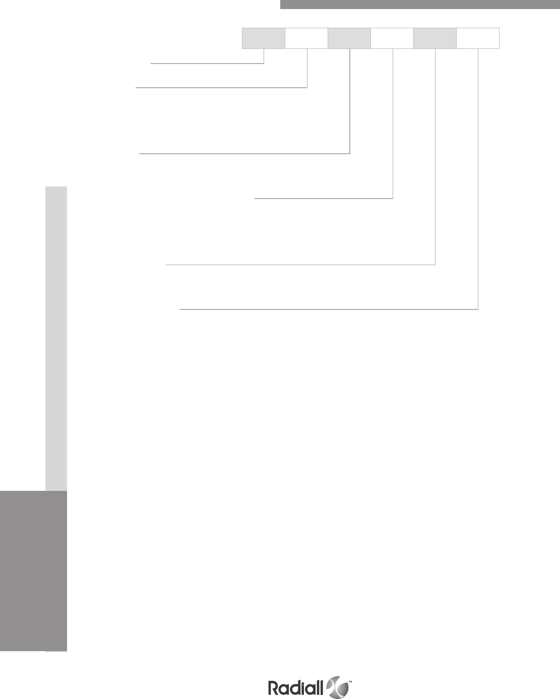
INSERTSDISCONNECT APPLICATIONRACK & PANEL APPLICATION CONTACTS EPX® SERIES
1-52 Go online for data sheets & assembly instructions Visit www.radiall.com and enter the part number
Our Most Important Connection is with You.™
EPX B3 P N 1 0
Series prefix
Shell size
B1: One cavity shell
B2: Two cavity shell
B3: Three cavity shell
B4: Four cavity shell
Shell style
P: Plug, nickel-plated
R: Receptacle, nickel-plated
Shell mounting (refer to page 1-54 for coding)
M: Plug, fixed connector with Ø3.96mm holes & 4-40UNC on side
N: Plug, fixed connector with 8-32 UNC & 4-40UNC on side
S: Receptacle, fixed with 4 x 8-32UNC
T: Receptacle, floating with 4 x 8-32 UNC (two axes) (1)
Polarization code
1: Shell delivered with polarizing keys unassembled
2: Shell delivered with no polarizing keys
Panel cut-out coding
A to Z: Receptacle, refer to page 1-59 for the code selection
0 (zero): Plug, no panel cut out coding
NOTE:
(1) This floating option is not available in EPXB4 version
How to Order EPXB1, B2, B3 & B4 Shell

DISCONNECT APPLICATIONRACK & PANEL APPLICATION CONTACTS INSERTS EPX® SERIES
1-53
Go online for data sheets & assembly instructions Visit www.radiall.com and enter the part number
Our Most Important Connection is with You.™
SHELL SELECTION PART
Series prefix
Shell size
B1: One cavity shell
B2: Two cavity shell
B3: Three cavity shell
B4: Four cavity shell
Shell style
P: Plug, nickel-plated
R: Receptacle, nickel-plated
Shell mounting (refer to page 1-54 for codes)
M: Plug, fixed connector with Ø3.96mm holes & 4-40UNC on side
N: Plug, fixed connector with 8-32 UNC & 4-40 UNC on side
S: Receptacle, fixed with 4 x 8-32 UNC
T: Receptacle, floating with 4 x 8-32 UNC (two axes) (1)
Panel cut-out coding
A to Z: For receptacle, refer to page 1-59 for the code selection
0 (zero): For plug, no panel cut out coding
INSERT SELECTION PART
Insert class
E: Environmental
N: Non-environmental (no rear grommet, no interfacial seal)
H: Non-environmental insert with a rear grommet (recommended for crimp contact)
T: Non-environmental insert with interfacial seal (recommended for PC tail contact)
Insert code
Refer to page 1-12 to select insert code
Contacts termination
XS: Female insert without contacts
XP: Male insert without contacts
SS: Female insert with crimp contacts
SP: Male insert with crimp contacts
YA: Gold PC tail contacts length A
ZA: Tin-lead PC tail contacts length A
RA: pure tin (RoHS) PC tail contacts length A
Assembly kit is delivered fully assembled including shell with inserts mounted, with or without contacts
according to the selection. When selecting your insert codes, do not forget to place them in the order
you want them assembled. Polarization keys are always provided unassembled with assembly kits.
Tips to help you in your selection:
- You are free to use either pin or socket inserts in EPXB plug or receptacle.
- Crimp contacts can be delivered with a kit, check which contacts will be included on page 1-12.
- If PC tail contacts are selected then all cavities including signal, power and quadrax are populated.
Size 5 coax cavities are not populated.
- If PC tail contacts are needed, remember that only straight pin PC tail contacts are available, and in plug only.
All connector inserts will use the same insert class and the same contact termination.
NOTE:
(1) This floating option is not available in EPXB4 version
EPX B4 P N 0 E ABDC YA
How to Order EPXB1, EPXB2, B3 & B4 Assembly Kit
These contacts are delivered uninstalled.
Refer to page 1- 54 to select PC tail contacts for plug
EPX B3 P N 1 0
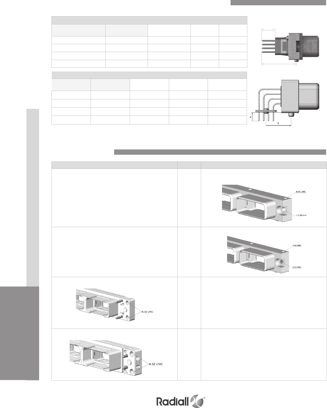
INSERTSDISCONNECT APPLICATIONRACK & PANEL APPLICATION CONTACTS EPX® SERIES
1-54 Go online for data sheets & assembly instructions Visit www.radiall.com and enter the part number
Our Most Important Connection is with You.™
Straight PC Tail contact termination
Mini Length E
mm (inch) Mini Length H
mm (inch) Gold Tin-lead Pure tin
(RoHS)
10.60 (0.417) (1) /YA ZA RA
13.80 (0.543) (1) /YB ZB RB
15.60 (0.614) (1) /YC ZC RC
19.55 (0.769) 5.40 (0.212) YD ZD RD
EPXB Shell Mounting
Right Angle PC Tail contact termination (2)
Mini length F
mm (inch)
Mini length E
mm (inch) Gold Tin-lead Pure tin (RoHS)
2.20 (0.086) 12.85 (0.505) (1) GA LA TA
3.60 (0.141) 20.10 (0.791) GB LB TB
3.60 (0.141) 12.85 (0.505) (1) GC LC TC
2.20 (0.141) 20.10 (0.791) GD LD TD
Receptacle side Code Plug sides
N/A M
Fixed connector with Ø 3.96 mm holes & 4-40 UNC front or side
mount
N/A N
Connector with 8-32 UNC & 4-40 UNC front or side mount
Fixed with 4 x 8-32 UNC panel rear mount
SN/A
Floating with 4 x 8-32 UNC panel rear mount
TN/A
NOTES:
(1) These PC tail lengths are not compatible with EPXBE and EPXBH inserts
(2) Right angle PC tail lengths GA, LA, TA and GD, LD, TD are not available for #5 and #8 power contacts
Contacts Termination for EPXB1, EPXB2, EPXB3 and EPXB4 Plugs
H
E
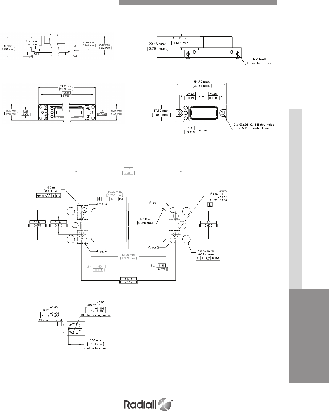
DISCONNECT APPLICATIONRACK & PANEL APPLICATION CONTACTS INSERTS EPX® SERIES
1-55
Go online for data sheets & assembly instructions Visit www.radiall.com and enter the part number
Our Most Important Connection is with You.™
PANEL CUT OUT (1)
PLUGRECEPTACLE
Floating Mount Fixed Mount
NOTE:
(1) The panel cut-out is shown from the rear of the panel
EPXB1 Shell Dimensions & Panel Cut-outs
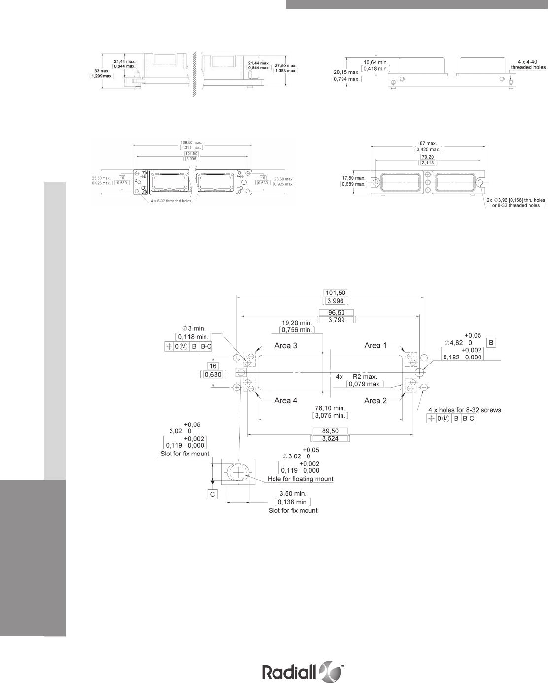
INSERTSDISCONNECT APPLICATIONRACK & PANEL APPLICATION CONTACTS EPX® SERIES
1-56 Go online for data sheets & assembly instructions Visit www.radiall.com and enter the part number
Our Most Important Connection is with You.™
PANEL CUT OUT (1)
PLUGRECEPTACLE
Floating Mount Fixed Mount
NOTE:
(1) The panel cut-out is shown from the rear of the panel
EPXB2 Shell Dimensions & Panel Cut-outs
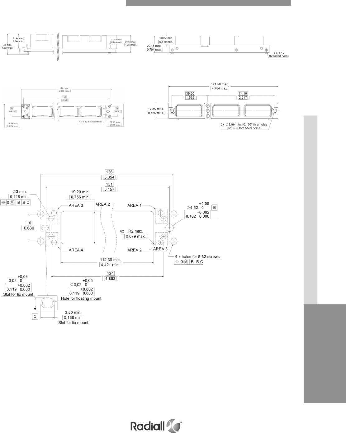
DISCONNECT APPLICATIONRACK & PANEL APPLICATION CONTACTS INSERTS EPX® SERIES
1-57
Go online for data sheets & assembly instructions Visit www.radiall.com and enter the part number
Our Most Important Connection is with You.™
PANEL CUT OUT (1)
NOTE:
(1) The panel cut-out is shown from the rear to the panel
PLUG
RECEPTACLE
x, y Floating Mount Fixed Mount
EPXB3 Shell Dimensions & Panel Cut-outs
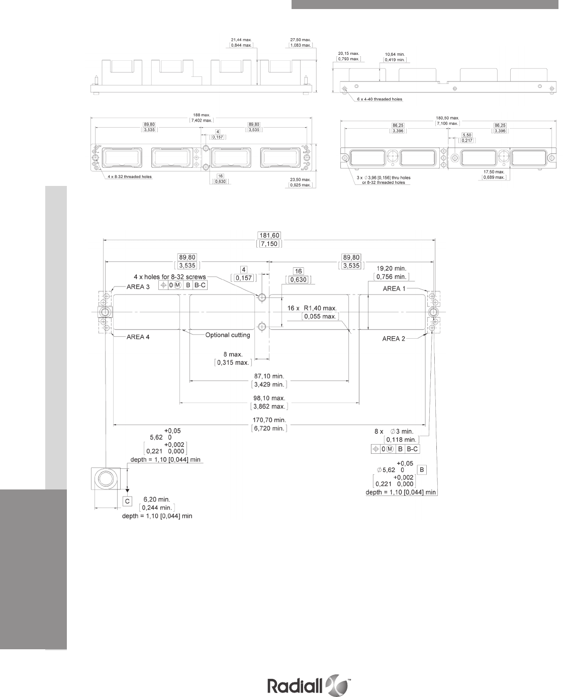
INSERTSDISCONNECT APPLICATIONRACK & PANEL APPLICATION CONTACTS EPX® SERIES
1-58 Go online for data sheets & assembly instructions Visit www.radiall.com and enter the part number
Our Most Important Connection is with You.™
RECEPTACLE
PANEL CUT OUT (1)
PLUG
NOTE:
(1) The panel cut-out is shown from the rear of the panel
EPXB4 Shell Dimensions & Panel Cut-outs
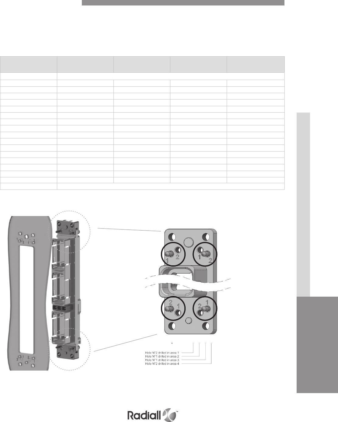
DISCONNECT APPLICATIONRACK & PANEL APPLICATION CONTACTS INSERTS EPX® SERIES
1-59
Go online for data sheets & assembly instructions Visit www.radiall.com and enter the part number
Our Most Important Connection is with You.™
When several EPXB connectors are used with the same equipment, a coding is available on the shell to
correlate the correct shell with the correct panel cut-out.
On the panel cut-out, four areas are coded, area 1, 2, 3 and 4 (see figure below). For each area, one of the
two holes should be drilled (hole n°1 or hole n°2). Each hole on the panel cut-out corresponds to the use
of a coding pin on the shell.
Panel cut-out coding Panel hole number
to drill in Area 1
Panel hole number
to drill in Area 2
Panel hole number
to drill in Area 3
Panel hole number
to drill in Area 4
AConnector delivered with coding device uninstalled
B 1 1 1 1
C 1 1 1 2
D 1 1 2 1
E 1 1 2 2
F 1 2 1 1
G 1 2 1 2
H 1 2 2 1
J 1 2 2 2
K 2 1 1 1
L 2 1 1 2
M 2 1 2 1
N 2 1 2 2
P 2 2 1 1
R 2 2 1 2
S 2 2 2 1
T 2 2 2 2
Z Connector delivered without coding pin(1)
Area 1Area 2
Area 3Area 4
2 1 1 2
Coding L:
CODING PINS ARE FOR RECEPTACLE ONLY
EPXB Panel Cut-out Coding
NOTE:
(1) Z panel cut out coding is only available with fix mounting
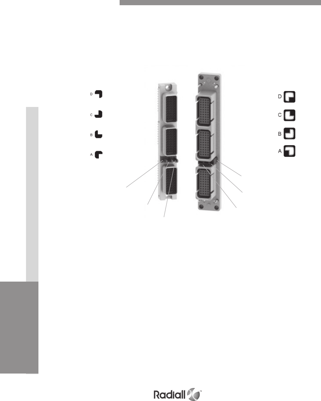
INSERTSDISCONNECT APPLICATIONRACK & PANEL APPLICATION CONTACTS EPX® SERIES
1-60 Go online for data sheets & assembly instructions Visit www.radiall.com and enter the part number
Our Most Important Connection is with You.™
EASY READING OF POLARIZATION CODE
Polarization device is included in the part number and could be installed as shown below
Each shell has 3 keys which can be in four different position
The three polarization keys can have their own position which allow a large range of codification
Connectors are shown front side with cavity A upwards
This is how you should read your code for either EPXB2 or EPXB3 or EPXB4
Plug size 3
Polarization post
Receptacle size 3
Polarization key
1
12
23
3
EPXB Polarization Code
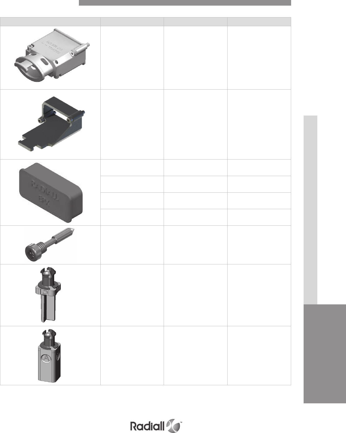
DISCONNECT APPLICATIONRACK & PANEL APPLICATION CONTACTS INSERTS EPX® SERIES
1-61
Go online for data sheets & assembly instructions Visit www.radiall.com and enter the part number
Our Most Important Connection is with You.™
Part number Description Assembly torque
617925073
EMI backshell
for receptacle only
(aluminium nickel-plated)
0.55±0.05 Nm
(4.87±0.44 in-lbs)
617922022
Straight strain relief for
receptacle only
(composite)
0.55±0.05 Nm
(4.87±0.44 in-lbs)
617954002 Dust cap for plug shell
(pink color) N/A
617954003 Dust cap for receptacle shell
(pink color) N/A
617954004 ESD dust cap plug shell
(black color) N/A
617954005 ESD dust cap receptacle shell
(black color) N/A
617980052 Coding Pin 0.8 Nm
(7 in-lbs)
617980054 Polarization post N/A
617980055 Polarization key N/A
Rack & Panel Accessories

INSERTSDISCONNECT APPLICATIONRACK & PANEL APPLICATION CONTACTS EPX® SERIES
1-62 Go online for data sheets & assembly instructions Visit www.radiall.com and enter the part number
Our Most Important Connection is with You.™
Part number Description EPXB
282521002 Insert extraction tool X
282521004 Right angle insert
extraction tool X
617954020 Plastic box to protect wired
inserts during handling X
F780855000
Hexagonal key 2mm
(5/64inch) Flats for
sleeve holder removal
X
282549041
Rem ov al t ool
for metal coding keys
(M81969/30-06)
X
Rack & Panel Tools
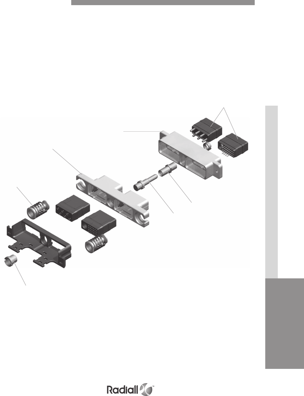
DISCONNECT APPLICATIONRACK & PANEL APPLICATION CONTACTS INSERTS EPX® SERIES
1-63
Go online for data sheets & assembly instructions Visit www.radiall.com and enter the part number
Our Most Important Connection is with You.™
Springs &
fixing axes
Plug shell
Receptacle
shell
Guide pin
Inserts with
contacts
Guide bush
Screw
The new EPXB2 Galley connector was specially designed for the severe conditions required by galley
equipment. A floating mechanism was developed to avoid any risk of jamming and to guarantee a fully
sealed connection.
The EPXB2 is used on ovens, beverage makers, refrigerators, microwave ovens and other equipment
which fit within the new standardized galley layouts.
The EPXB2 connector is modular and provides extra contact density to add new contacts such as the #8
Twinax CAN data bus contact. Backshell accessories are also available.
Detailed view of receptacle and plug with accessories for the EPXB2 galley connector
EPX Galley Product Overview
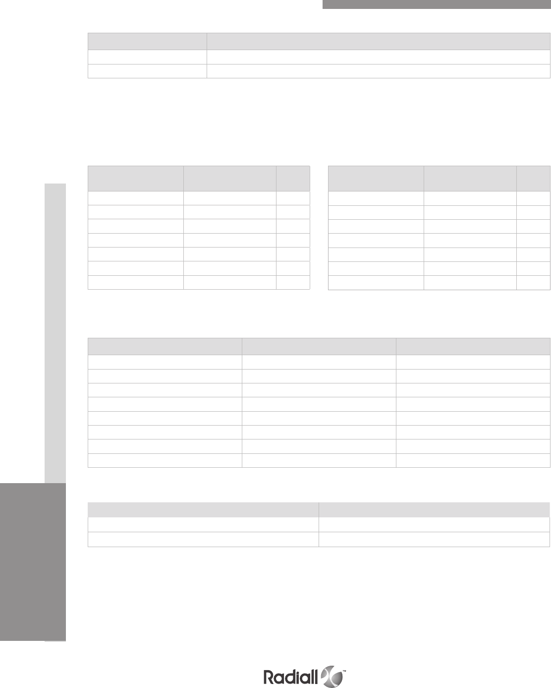
INSERTSDISCONNECT APPLICATIONRACK & PANEL APPLICATION CONTACTS EPX® SERIES
1-64 Go online for data sheets & assembly instructions Visit www.radiall.com and enter the part number
Our Most Important Connection is with You.™
RECEPTACLE AND PLUG ASSEMBLY KIT
Each item included in the kit is indicated in the table below and can also be ordered separately
Part number Description
617610188 or 617610558 Receptacle assembled kit (*)
617610189 Plug assembled kit (*)
(*)Part numbers for assembly kits include: plug or receptacle shell, inserts, contacts, sealing plugs and dust caps.
PLUG KIT
How to Order EPX® Galley Equipment Connector
Part number Description Quantity per kit
617610213 Plug shell 1
EPXBE25Q1SA Insert for cavity A 1
EPXBE06SB Insert for cavity B 1
617300 Socket crimp contacts/Size 22 15
617350 Socket crimp contacts/Size 12 6
616910 Filler plug 9
617922007 Strain relief 1
617954002 Dust cap 2
CAN DATA BUS CONTACTS
Part number Description
617165011 Size 8 Twinax pin contact
617065011 Size 8 Twinax pin contact
Part number Description Quantity
per kit
617610212 Receptacle shell 1
EPXBE25Q1PA Insert for cavity A 1
EPXBE06PB Insert for cavity B 1
617200 Pin crimp contacts/Size 22 15
617250 Pin crimp contacts/Size 12 6
616910 Filler plug 9
617954003 Dust cap 2
617610188
Part number Description Quantity
per kit
617610419 Receptacle shell 1
EPXBE25Q1PA Insert for cavity A 1
EPXBE06PB Insert for cavity B 1
617200 Pin crimp contacts/Size 22 15
617250 Pin crimp contacts/Size 12 6
616910 Filler plug 9
617954003 Dust cap 2
Shell with 2 thru holesShell with 2 self-locking threaded holes
RECEPTACLE KITS
617610558
617610189 contents
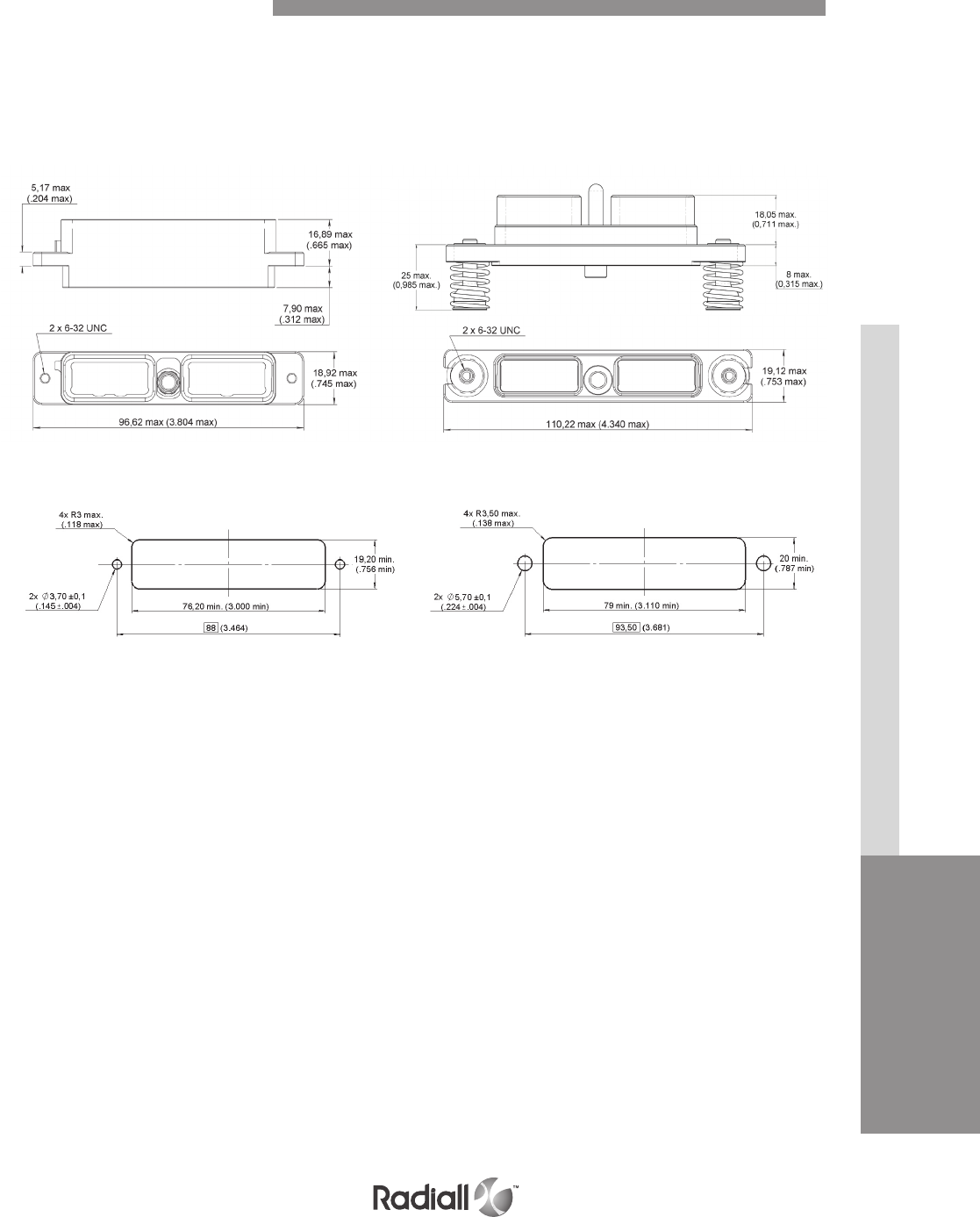
DISCONNECT APPLICATIONRACK & PANEL APPLICATION CONTACTS INSERTS EPX® SERIES
1-65
Go online for data sheets & assembly instructions Visit www.radiall.com and enter the part number
Our Most Important Connection is with You.™
PANEL CUT OUT
RECEPTACLE
Front mount
PLUG
Rear mount
EPX® GALLEY EQUIPMENT CONNECTOR PER ARINC 800
Dimensions and Panel Cut Out
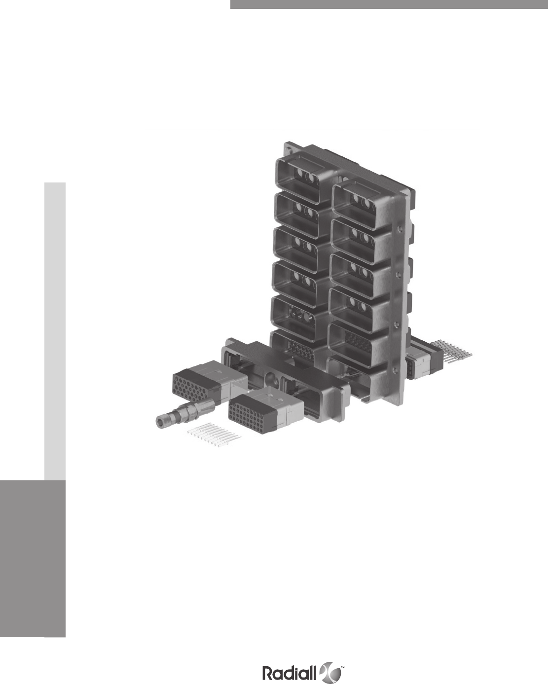
INSERTSDISCONNECT APPLICATIONRACK & PANEL APPLICATION CONTACTS EPX® SERIES
1-66 Go online for data sheets & assembly instructions Visit www.radiall.com and enter the part number
Our Most Important Connection is with You.™
Multi-gang EPX® Connectors
A whole range of multigang connectors is available for disconnect and rack and panel applications.
Multigang connectors features and benefits:
- Weight saving design
- Make installation easier and quicker
- Utilize EPX modularity and its whole range of inserts
- Take advantage of EPX connectors functionalities and use EPXB2 standard plug shells
with a multigang shell
Specifications
- Several cavities for EPXB inserts : from 4 to 20 cavities
- Standard EPX strain reliefs and backshells available
- In accordance with EN4644 performances
Several options are available:
- Grounding block
- Grounding spring fingers
- Float mounting
- Spring loaded mounting

Our Most Important Connection is with You.™

Quick Multipin Series
SECTION 2

Our Most Important Connection is with You.™

2-3
Our Most Important Connection is with You.™
Go online for data sheets & assembly instructions Visit www.radiall.com and enter the part number
SECTION 2 TABLE OF CONTENTS
Contents
Introduction ....................................................................................................................2-4
Features & benefits ............................................................................................................ 2-5
Electrical characteristics .....................................................................................................2-6
Mechanical and environmental characteristics ............................................................................ 2-7
Insert selection table ..........................................................................................................2-8
How to order EPX insert ....................................................................................................... 2-9
EPXA inserts arrangements .................................................................................................2-10
EPXB inserts arrangements ........................................................................................ 2-11 to 2-12
Signal & power crimp contacts ..................................................................................... 2-13 to 2-14
Coaxial crimp contacts & Twinax & Triax crimp contacts ................................................................2-15
Quadrax & BMA crimp contacts .............................................................................................2-16
LuxCis® fiber optic contacts .................................................................................................2-17
QM size A product overview ..................................................................................................2-18
QM size B product overview .................................................................................................. 2-19
How to order QM shell ........................................................................................................2-20
Polarization code ..............................................................................................................2-21
QM size A shell dimensions ..................................................................................................
2-22
QM size B shell dimensions
..................................................................................................
2-23
How to order QM mounting device
..........................................................................................
2-24
L-Bracket dimensions
........................................................................................................
2-25
Single sided rails range
..................................................................................................... 2
-26
Single sided rails dimensions
......................................................................................
2-27 to 2-29
Double sided rails dimensions
..............................................................................................
2-30
Accessories
....................................................................................................................
2-31
Spare parts and tools
........................................................................................................
2-32
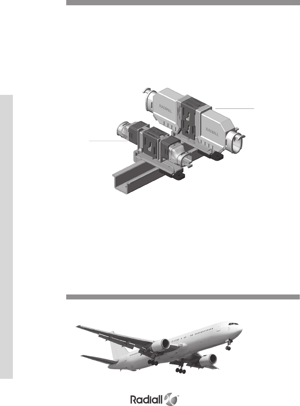
QM SERIES
2-4
Our Most Important Connection is with You.™
Go online for data sheets & assembly instructions Visit www.radiall.com and enter the part number
Introduction
Applications
A MODULAR AND TOOL LESS CONNECTOR
Radiall QM series connectors are designed for use with in-line disconnect applications on commercial
airplanes. QM series offer outstanding electrical performances and are designed with environmental
and mechanical characteristics that provide long lasting durability needed for the most severe
aerospace applications.
Two connector sizes are available in QM series to optimize disconnect connection in terms of weight and
density in an aircraft wiring system:
- QM size A
- QM size B
QM series is developed to provide the following benefits:
- Save time during wiring with a tool less connector
- Save weight with a composite connector
- implify the wiring design as no panel cut outs are needed
QM size A and size B are mounted on the same range of rails. QM size A will save weight and space
when a smaller insert with less contacts can be utilized in the wiring design compared to the QM size
B. QM series offer a wide range of inserts that cover all contact technology. It is manufactured under US
patent App, No 11/614.642. QM series is available worldwide.
Interconnect solution for aerospace and harsh environment applications
QM SIZE A
QM SIZE B
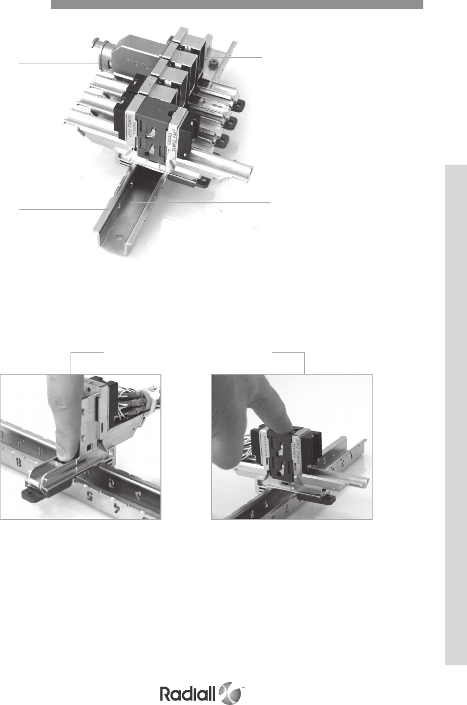
QM SERIES
2-5
Our Most Important Connection is with You.™
Go online for data sheets & assembly instructions Visit www.radiall.com and enter the part number
Lightweight
Click to install Push to lock
High conductive rails
Perfect, clean
and efcient
Exceptional quality
User friendly - no tools needed
Simple, clean
and efficient
Features & Benefits
QM SERIES
2-6
Our Most Important Connection is with You.™
Go online for data sheets & assembly instructions Visit www.radiall.com and enter the part number
Electrical Characteristics
Contacts are per EN3155-76 and EN3155-77. Electrical characteristics conform to SAE AS 39029 (MIL-C-39029 type A).
OTHER CHARACTERISTICS
- Shell to shell conductivity < 2.5 m Ω, operating voltage: 400 Vrms or 500 Vdc at sea level
- Voltage stability (ground block): Maximum variation 4mV SAE AS 81714 (MIL-T-81714)
- Magnetic permeability < 2 and comparative tracking index = 250 V
- Lightning strike: 3.6kA according to EIA-364, Test procedure 75, Type B Test level 1
GROUND BLOCK CONTACT
Contact with wire size Max Current Amps
Contact to contact Contact + AWG20 7.5
Contact to mounting surface Contact + AWG20 7.5
CONTACTS
Note 1: Size 5 contacts are not part of SAE AS 39029 (MIL-C-39029 type A). They are qualified by Radiall to 46 Amps
Contact size Wire size Max Current Amps
AWG22 5
22 AWG24 3
AWG26 2
20
AWG20 7.5
AWG22 5
AWG24 3
16
AWG16 13
AWG18 10
AWG20 7.5
12
AWG12 23
AWG14 17
AWG16 13
8AWG8 46
AWG10 33
5AWG8 46 — See note 1
AWG10 33
EMI SHIELDING EFFECTIVENESS
Frequency (MHz) Leakage attenuation (dB)
100 65
200 63
300 61
400 59
500 58
DIELECTRIC WITHSTANDING VOLTAGE
EIA 36420 (M I L S T D -1344 / Method 3001.1) with leakage current < 1m Ω
Level Environmental inserts Voltage (VRMS) Non-environmental voltage (VRMS)
Sea level 1500 1500
50000 feet 800 600
70000 feet 800 300
INSULATION RESISTANCE
EIA 36421 MILSTD1344 / Method 3003.1
Temperature Insulation resistance
Ambient temperature > 5000 M
155°C (+347°F) >200 M
QM SERIES
2-7
Our Most Important Connection is with You.™
Go online for data sheets & assembly instructions Visit www.radiall.com and enter the part number
Mechanical and Environmental Characteristics
Vibration and Shock
MECHANICAL CHARACTERISTICS
Interruption shall not exceed 1s, they are measured on electrical contacts, between shells and
between shell and rail.
Shell type Material
Vibration Shock
for 5 hours in each of the 3 axis/interruption
< 1µs EIA 364-28 three shocks in each axis EIA 364-27
(MIL-STD-1344 /Method 2004.1) condition A
(MIL-STD-1344 /Method 2005.1)
QM Series Composite
4 positions rail = Acceleration 13,8 Grms 0,2G²/Hz from 10
to 400HZ and 0,03G²/hz from 400 to 2000Hz
4 positions rail = Shock amplitude
50G / duration 11ms
22 positions rails = Acceleration 6,2 Grms
0.04 g²/Hz from 10 to 400 Hz 0.006 g²/Hz at 2000 Hz
22 positions rail = Shock amplitude
15G / duration 11ms
RETENTION CHARACTERISTICS
Contact retention EIA 364-29 (MIL-STD-1344 / Method 2007.1) on terminated connectors
- Insert retention: 400N (90lbs) (EIA 364-35 = MIL-STD-1344 /Method 2010.1)
- Max displacement: 0.30mm (.012 in.)
Contact size Retention force Max displacement
Ground block 88N (20lbs) 0.30mm (.012 in.)
22 53.4N (12lbs) 0.38mm (.015 in.)
20 89N (20 lbs) 0.38mm (.015 in.)
16 111.2N (25lbs) 0.38mm (.015 in.)
12 133.45N (30lbs) 0.38mm (.015 in.)
8 133.45N (30lbs) 0.38mm (.015 in.)
5 133.45N (30lbs) 0.38mm (.015 in.)
OTHER CHARACTERISTICS
- Salt spray: 96 hours (Nickel plating) EIA 364-26 (MIL-STD-1344 / Method 1001.1) test condition A
- Humidity: 10 days with temperature variation from -10°C to +65°C EIA 364-31 Method 4,
test condition B (MIL-STD-1344 /Method 1002.2, type II test condition)
- Altitude immersion: 3 cycles at 50 000 feet EIA 364-03 (MIL-STD-1344 /Method 1004.1)
- For more detail please refer to QM product specification
ENVIRONMENTAL CHARACTERISTICS
Temperature
- Temperature range: -65°C / +155°C
- Temperature life: 1000H at 155°C
Shell type Material Mating/unmating Mating force
QM size B Nickel plated composite 50 cycles 250N max
QM size A 125N max
Mating/unmating
QM SERIES
INSERTS
CONNECTORS & ACCESSORIES CONTACTS
2-8
Our Most Important Connection is with You.™
Go online for data sheets & assembly instructions Visit www.radiall.com and enter the part number
Inserts Selection Table
QM size B connectors will use EPXB inserts range when QM size A connectors will use EPXA inserts.
Only signal and power contacts with an asterisk (*) can be delivered with inserts. All other contacts must
be ordered separately (coax, twinax, quadrax and fiber optic contacts).
Series
Insert
name
Insert
code
Contact Size & Type
22* 20* 15 or 16* 16 16 12* 8 8 8 5 5
Total
contacts
Signal Power Power or
coax
LuxCis®
fiber optic
Power in
fiber optic
cavity
Power or
coax Power
Quadrax
or
twinax
BMA Coax or
triax Power
EPXA
00 0 0
1C1 A11
1P1 B11
04 C2 2 4
09 D3 6 9
14 E14 14
14M F8 3 3 14
17 G12 517
20 H20 20
F6 J66
EPXB
00 0 0
C3 A33
P3 B33
3Q3 C33
06 D66
10Q2 E8 2 10
12F6 F6 6 12
F12C G12 12
13C1 H6 4 2 1 13
13P1 J6 4 2 1 13
14 K14 14
17 L14 317
20C1 M19 120
20P1 N19 120
22 P16 622
22V Q16 622
25P1 R24 125
25Q1 S24 125
28 T22 628
30 U30 30
34 W18 16 34
40 X40 40
48 Y48 48
3T3 Z33
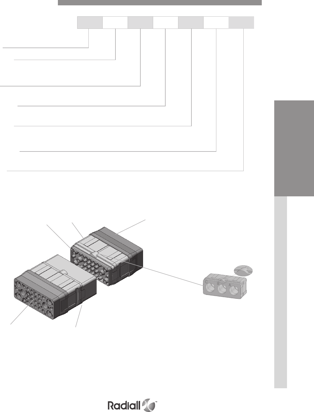
QM SERIES
INSERTS
CONTACTS
CONNECTORS & ACCESSORIES
2-9
Our Most Important Connection is with You.™
Go online for data sheets & assembly instructions Visit www.radiall.com and enter the part number
Series
Insert size
A: insert for QM size A
B: insert for QM size B
Class
E: Environmental
Insert name
Refer to table on page 2-10 for inserts arrangement
Insert type
P: Pin
S: Socket
Insert keying
A: insert with keying A
Contact
Without code: insert delivered without contact
S: Signal and power crimp contacts are delivered with insert but uninstalled (refer to page 2-8)
Inserts 00, 1C1, 1P1, F6, C3, P3, 3Q3, 12F6, F12C and 3T3 are not available in S contact version
EPX B E 40 P A S
Socket insert
Rear grommet
Interfacial seal Pin insert Rear grommet
Keying A
How to Order EPX Insert

QM SERIES
INSERTS
CONNECTORS & ACCESSORIES CONTACTS
2-10
Our Most Important Connection is with You.™
Go online for data sheets & assembly instructions Visit www.radiall.com and enter the part number
Insert name 00
Blank insert (1)
Insert name 1C1
1 x size 5 coax contact
Insert name 1P1
1 x size 5 power contact
Insert name 04
2 x size 15 or 16 contacts
2 x size 12 contacts
Insert name 09
3 x size 20 contacts
6 x size 15 or 16 contacts
Insert name 14
14 x size 20 contacts
Insert name 14M
8 x size 22 contacts
3 x size 20 contacts
3 x size 15 or 16 contacts
Insert name 17
12 x size 22 contacts
5 x size 20 contacts
Insert name 20
20 x size 22 contacts
Insert name F6
6 x size 16 optical LuxCis® termini
EPXA Inserts Arrangements
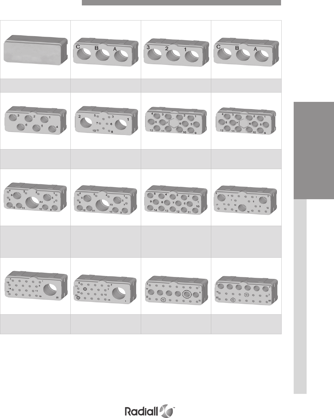
QM SERIES
INSERTS
CONTACTS
CONNECTORS & ACCESSORIES
2-11
Our Most Important Connection is with You.™
Go online for data sheets & assembly instructions Visit www.radiall.com and enter the part number
Full size inserts arrangements are compliant with EN4644.
Insert name 00
Dummy insert
Insert name C3
3 x size 5 contacts
Insert name P3
3 x size 5 power contacts
Insert name 3Q3
3 x size 8 quadrax contacts
Insert name 06
6 x size 12 contacts
Insert name 10Q2
8 x size 20 contacts
2 x size 8 quadrax contacts
Insert name 12F6
6 x size 16 Optical LuxCis® termini
6 x size 16 special electrical contacts
Insert name F12C
12 x size 16 Optical LuxCis® termini
Insert name 13C1
6 x size 20 contacts
4 x size 15 or 16 contacts
2 x size 12 contacts
1 x size 5 contact
Insert name 13P1
6 x size 20 contacts
4 x size 15 or 16 contacts
2 x size 12 contacts
1 x size 5 power contact
Insert name 14
14 x size 15 or 16 contacts
Insert name 17
14 x size 20 contacts
3 x size 12 contacts
Insert name 20C1
19 x size 20 contacts
1 x size 5 contact
Insert name 20P1
19 x size 20 contacts
1 x size 5 power contact
Insert name 22
16 x size 20 contacts
6 x size 15 or 16 contacts
Insert name 22V
16 x size 20 contacts
6 x size 16 contacts
EPXB Inserts Arrangements
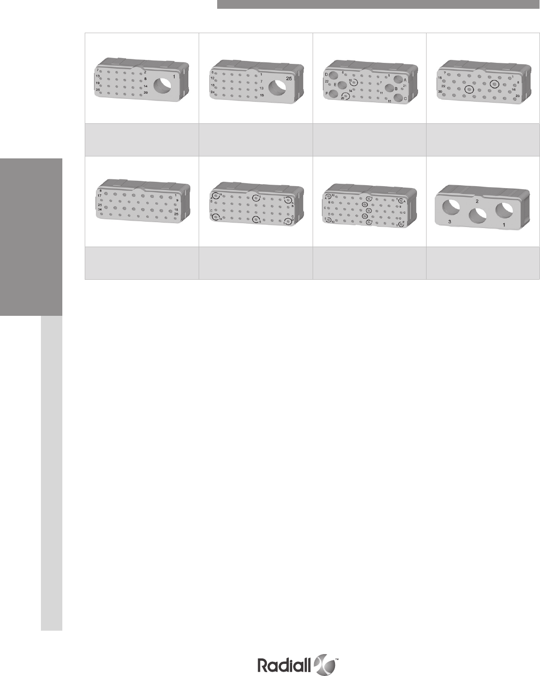
QM SERIES
INSERTS
CONNECTORS & ACCESSORIES CONTACTS
2-12
Our Most Important Connection is with You.™
Go online for data sheets & assembly instructions Visit www.radiall.com and enter the part number
Insert name 25P1
24 x size 22 contacts
1 x size 8 power contact
Insert name 25Q1
24 x size 22 contacts
1 x size 8 quadrax contact
Insert name 28
22 x size 22 contacts
6 x size 15 or 16 contacts
Insert name 30
30 x size 20 contacts
Insert name 34
18 x size 22 contacts
16 x size 20 contacts
Insert name 40
40 x size 22 contacts
Insert name 48
48 x size 22 contacts
Insert name 3T3
3 x size 8 BMA contact
(1)
Full size inserts arrangements are compliant with EN4644.
NOTE:
(1) 3T3 pin insert only is available. It is mateable with 3Q3 socket insert
EPXB Inserts Arrangements
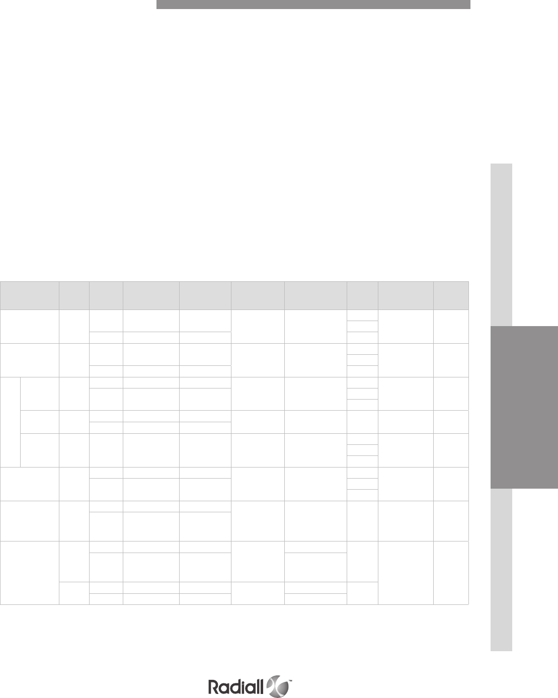
QM SERIES
INSERTS
CONTACTS
CONNECTORS & ACCESSORIES
2-13
Our Most Important Connection is with You.™
Go online for data sheets & assembly instructions Visit www.radiall.com and enter the part number
Signal & Power Crimp Contacts
QM series offers a wide range of contacts compliant with EN3155 and SAE AS 39029. This range covers
any technology in aerospace application using either cable or printed circuit boards’ solutions:
- Signal and power contacts
- High frequency with coax, twinax and triax contacts
- Ethernet links with Quadrax contacts
- Optical links with LuxCis® contacts
Discover our brand new range of signal & power contacts with gold selective plating
Features and benefits :
- Significant reduction of cost of ownership
- Reduced dependence to gold rate fluctuation
- No change in the contact integration process
Specifications:
- Same contact design as full plated version
- Contact interface gold plated with 1.27m
- For crimp version, no consequence on crimping process
- For PC tail version, use of selective plated contacts has no impact on PCB design
- Product qualification is available upon request
Notes
(1) Electrical contacts for optical inserts are always pin contacts (hermaphrodite)
(2) In order to make these contacts environmental, it is necessary to add a sealing boot. Please, contact us for additional information
(3) These power contacts can be used in power inserts only (25P1 EPXB insert)
(4) These power contacts can be used in power inserts only (P3, 13P1 and 20P1 EPXB inserts)
Contact size Wire
size Type Part number
full plated
Part number
selectively
plated
Crimping tool Positioner Selector Ins / ext tool Type of
tool
22
22 Pin 617200 617200100 282281
M22520/2-01 282970
M22520/2-23
4
282522
(M81969/14-01) Plastic24 3
26 Socket 617300 617300100 3
20
20 Pin 617221 617221100 282281
M22520/2-01 282971
M22520/2-08
7
282522001
(M81969/39-01) Plastic22 6
24 Socket 617320 617320100 5
16
16 Pin 617240 617240100
282291
M22520/1-01 282972
M22520/1-02
6
282515
(M81969/14-03) Plastic18 Socket 617340 617340100 5
20 4
Ground
block 20 Pin 617221050 n/a 282281
M225520/2-01 282581015
M22520/2-11 7282886 Metal
Socket N/A n/a
for optical
electrical
insert
16
Pin 617235003
(1)
n/a 282291
M22520/1-01 282581013
6
282515
(M81969/14-03) Plastic18 5
20 4
12
12 Pin 617250 617250100
282291
M22520/1-01 282972
M22520/1-02
8
282549004
(M81969/14-04) Plastic14 Socket 617350 617350100 7
16 6
8
8Pin 617291002
(2&3)
n/a R282600000
M22520/23-01
+ Die set
R282650000
M22520/23-02
282588 n/a 282549001 Metal
10 Socket 617391002
(2&3)
n/a
5
8Pin 617280
(2&4)
n/a R282600000
M22520/23-01
+ Die set
R282650000
M22520/23-02
282557020
n/a
282946
(M81969/28-01) Metal
10 Socket 617390
(2&4)
n/a 282557021
12 Pin 617260001
(2&4)
n/a 282613 282586003 6
16 Socket 617370001
(2&4)
n/a 282586005

QM SERIES
INSERTS
CONTACTS
CONNECTORS & ACCESSORIES
2-14
Our Most Important Connection is with You.™
Go online for data sheets & assembly instructions Visit www.radiall.com and enter the part number
Contact size Wire
size Type Part number
fully plated Crimping tool Positioner Selector Ins / ext tool Type of
tool
22
reduced crimp
barrel
28 Pin 617201(1) 282281
M22520/2-01
282970
M22520/2-23
5
282522
(M81969/14-01) Plastic
30 Socket 617301(1) 4
oversize crimp
barrel
20 Pin 617200200
282281
M22520/2-01
282970
M22520/2-23
5
22 Socket 617300200 4
24 3
20
reduced crimp
barrel
22 Pin 617224001(1)
282281
M22520/2-01
282971
M22520/2-08
4
282522001
(M81969/39-01) Plastic
24 Socket 617324001(1) 3
26 3
oversize crimp
barrel
18 Pin 617221200
282281
M22520/2-01
282971
M22520/2-08
5
20 Socket 617320200 5
22 4
16
reduced crimp
barrel
20 Pin 617241(1)
282291
M22520/1-01
282972
M22520/1-02
5
282515
(M81969/14-03) Plastic
22 Socket 617341(1) 5
24 4
reduced crimp
barrel for opti-
cal electrical
insert
20
Pin 617235002(1&2) 282291
M22520/1-01 282581013
5
22 5
24 4
oversize crimp
barrel
14 Pin 617240200
282291
M22520/1-01
282972
M22520/1-02
6
16 Socket 617340200 5
18 5
Signal & Power Crimp Contacts
NOTES:
(1) When smaller wire sizes are used on contacts with reduced crimp barrel, the wire will not provide sealing to the grommet. If sealing is
required, please contact Radiall
(2) Electrical contacts for optical insertss are always pin contacts (hermaphrodite)
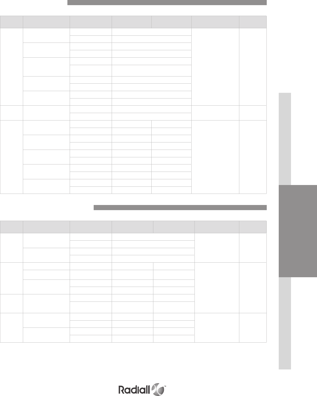
QM SERIES
INSERTS
CONTACTS
CONNECTORS & ACCESSORIES
2-15
Our Most Important Connection is with You.™
Go online for data sheets & assembly instructions Visit www.radiall.com and enter the part number
Contact
size Cable type Type Environmental part
number
Non-environmental
part number Ins/ext tool Type of tool
15-16
RG174-RG179 RG316 Pin 617130
282512 Metal
Socket 617030
RG178 Pin 617131
Socket 617031
GORE/AXON P812817
FILECA F1703-134
FILOTEX SP132868
Pin 617132
Socket 617032
RG178 DT Pin 617133
Socket 617033
UT .047 Pin 617135
Socket 617035
12 UT.085-RG405 Pin 617160 282549004 (M81969/14-
04) Plastic
Socket 617060
5
RG58-RG141 Pin 617101001 617101
282946
(M81969/28-01) Metal
Socket 617001001 617001
RG142 - RG400 Pin 617102001 617102
Socket 617002001 617002
RG174-RG316 RG188 Pin 617103001 617103
Socket 617003001 617003
RG178-RG196 Pin 617104001 617104
Socket 617004001 617004
RG180 Pin 617105001 617105
Socket 617005001 617005
Contact
size Cable type Type Environmental part
number
Non-environmental
part number Ins/ext tool Type of tool
12 Triax
ECS0700 Pin 617190010
282549004
(M81969/14-04) Plastic
Socket 617090010
M17/176-00002 Pin 617190012
Socket 617090012
8 Triax
TENSOLITE Pin 617165021 617165020
282549001
(M81969/28-03) Metal
24473/03159X-2 Socket 617065021 617065020
WHITMOR
W26751575
Pin 617165 617165001
Socket 617065 617065001
8 Twinax
ABS0386WF24
& TYCO
1726A1424A
Pin 617165011 620165010
Socket 617065011 620065010
5 Triax
M17/176-0002 Pin 617150001 617150
282946
(M81969/28-01) Metal
Socket 617050001 617050
PAN6421 Pin 617152001 617152
Socket 617052001 617052
Coaxial Crimp Contacts
Twinax and Triax Crimp Contacts
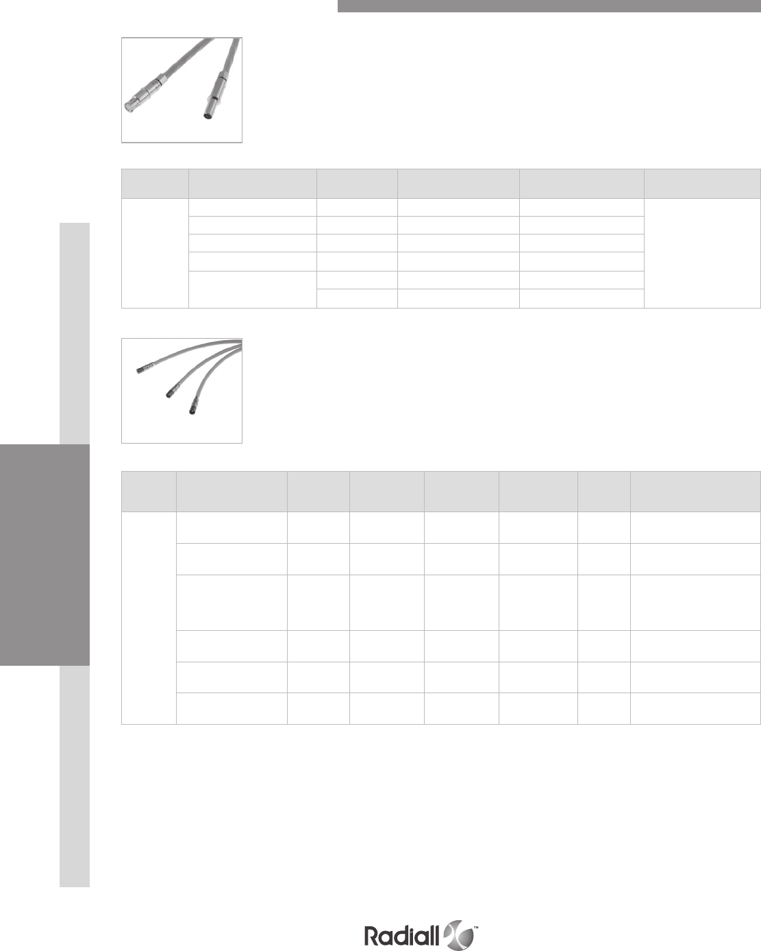
QM SERIES
INSERTS
CONTACTS
CONNECTORS & ACCESSORIES
2-16
Our Most Important Connection is with You.™
Go online for data sheets & assembly instructions Visit www.radiall.com and enter the part number
Contact size Cable type Type Environmental
part number
Non-environmental
part number Extraction tool in metal
8
Ethernet cable Pin 617175011 617175012
282549001
ABS0972 & ABS1503 Socket 617075011 620075010
TENSOLITE Pin 617175051 617175052
NF24Q100 Socket 617075051 620075050
Tensolite NF26Q100
JSF Y18
Pin 617175053 617175054
Socket 617075053 620075021
QUADRAX CONTACTS
Contact
size Cable type Connector
Type
Environmental
part number
Non-environ-
mental part
number
Frequency
range
Max
VSWR Insertion loss
8
SHF5 - SHF5M(1) Pin(2) 617171011 617171010 DC-18 GHz 1.35 0.13 dB at max frequency
(18 GHz)
RG142 Pin(2) 617171021 617171020 DC-12.4 GHz 1.35 0.11 dB at max frequency
(12.4 GHz)
SHF2.4M
(1) / UT.085
Harbour SS405
Times Tflex405
Pin(2) 617171031 617171030 DC-18 GHz 1.35 0.13 dB at max frequency
(18 GHz)
SHF5 - SHF5M(1) Socket 617071011 617071010 DC-18 GHz 1.35 0.13 dB at max frequency
(18 GHz)
RG142 Socket 617071021 617071020 DC-12.4 GHz 1.35 0.11 dB at max frequency
(12.4 GHz)
SHF3(1) Socket 617071041 617071040 DC-18 GHz 1.35 0.13 dB at max frequency
(18 GHz)
BMA CONTACTS
Extraction tool 282549001 is used for size 8 BMA contacts.
Environmental BMA contacts are all provided with sealing boots.
NOTES:
(1) The BMA contacts which can accommodate SHF cables requires a wiring done by Radiall .Please contact Radiall for information
(2) Pin BMA can only be installed in modified EPXB Quadrax insert such as 3T3P. Ex: EPXBE3T3PA
Quadrax & BMA Crimp Contacts

QM SERIES
INSERTS
CONTACTS
CONNECTORS & ACCESSORIES
2-17
Our Most Important Connection is with You.™
Go online for data sheets & assembly instructions Visit www.radiall.com and enter the part number
The LuxCis® product range is a proven, flexible and always expending fiber optic interconnect solution
offering high speed communication in aerospace and other harsh environments.
NOTE:
Radiall can support you with your cable and harness assemblies
Please contact your sales representative
OPTICAL PERFORMANCES
LUXCIS® CONTACTS
MECHANICAL AND ENVIRONMENTAL CHARACTERISTICS
MultiMode (PC)
850 / 1300 nm
SingleMode (UPC)
1310 / 1550 nm
Insertion Loss (IL) Mean
(IEC 61300-3-4 Method B)
0.1 dB 0.15 dB
Return Loss (RL)
(IEC 61300-3-6)
> 20 dB > 50 dB
Standard Performances
Thermal cycling
SAE AS 13441 method 1003.1 -55°C/+125°C (cable dependant)
Temperature
Endurance
TIA/EIA 455-4 1000 h @ 125°C (cable dependant)
Vibration
TIA/EIA 455-11 27 Grms
Shocks
TIA/EIA 455-14 50 G, 11 ms
Durability
TIA / EIA 364-09 500 cycles
Maintenance ageing
SAE AS 13441 method 2002.1 10 cycles
Cable retention
Cable retention
1.8 mm diameter
900 m diameter
SAE AS 13441 method 2009.1 68 N
7 N
Humidity TIA EIA 455-5
10 cycles / 24 h
90% RH
-25°C / +65°C
LUXCIS® CONTACT PART NUMBERING SYSTEM
F725 0 03 419
Cable type and diameter
118:
900 m cable
318: 1.2 mm cable with strengthening
members, tight structure
419: 1.6 to 2.2 mm cable, loose structure
519: 1.6 to 2.2 mm cable, tight structure
F725 : LuxCis® series
Ferrule type
00:
PC ferrule for SingleMode fiber
03: PC ferrule for 50/125 or 62,5/125 um MultiMode fiber
04: PC ferrule for 100/40 um MultiMode fiber
05: PC ferrule for 200/230 um MultiMode fiber
50: APC ferrule for SingleMode fiber
LuxCis® Fiber Optic Contacts
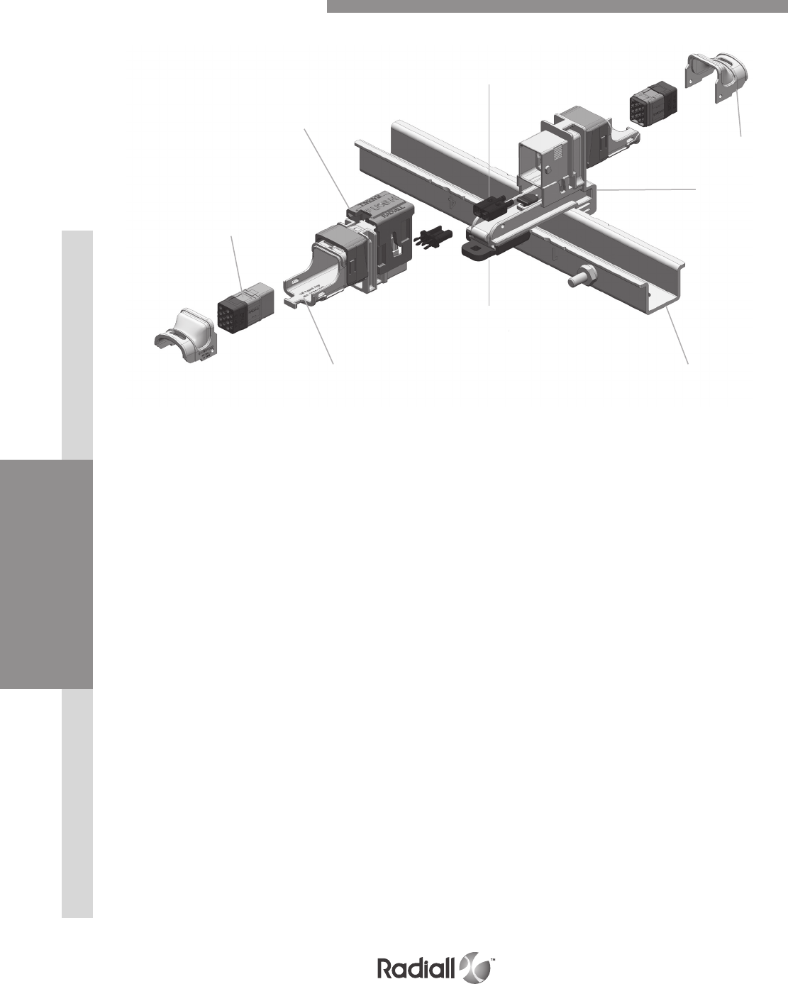
QM SERIES
INSERTS
CONTACTS
CONNECTORS & ACCESSORIES
2-18
Our Most Important Connection is with You.™
Go online for data sheets & assembly instructions Visit www.radiall.com and enter the part number
EMI backshell
Insert
Plug with slide
locking device
Polarization keys
Single sided rail
Latching system
Integrated strain relief
QM Size A Product Overview
Receptacle
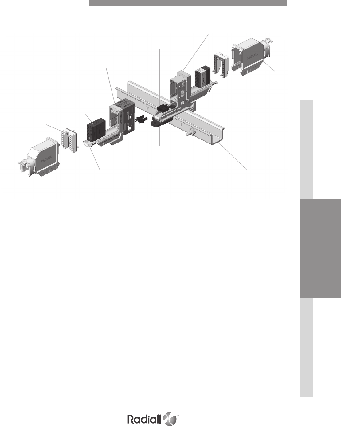
QM SERIES
INSERTS
CONTACTS
CONNECTORS & ACCESSORIES
2-19
Our Most Important Connection is with You.™
Go online for data sheets & assembly instructions Visit www.radiall.com and enter the part number
EMI backshell
Grounding block
Insert
Single sided rail
QM Size B Product Overview
Plug with slide
locking device
Polarization keys
Receptacle
Latching system
Integrated strain relief

Our Most Important Connection is with You.™
QM SERIES
INSERTS
CONTACTS
CONNECTORS & ACCESSORIES
2-20 Go online for data sheets & assembly instructions Visit www.radiall.com and enter the part number
Series
Shell Size
A: QM size A shell
B: QM size B shell
Product Type
C: Plug (size A)
D: Receptacle (size A)
P: Plug (size B)
R: Receptacle (size B)
W: Plug with ground block (size B)
(1)
Z: Receptacle with ground block (size B)
(1)
Finish
N: Nickel plating
Polarization
00: delivered without polarizing keys
Without code: delivered with polarizing keys not installed
**: delivered with polarizing keys installed according to code (see table 2 on page 2-18)
QM B P N 00
NOTE:
(1) Shells with groung block are not compatible with EMI backshell
How to Order QM Shell

QM SERIES
INSERTS
CONTACTSCONNECTORS & ACCESSORIES
2-21
Our Most Important Connection is with You.™
Go online for data sheets & assembly instructions Visit www.radiall.com and enter the part number
Code on polarization keys Code on polarization posts
Polarization Code
16 possible codings are available
Key position A A A A B B B B C C C C D D D D
Key position A B C D A B C D A B C D A B C D
Polarization keys Polarization posts
View shows A & D View shows C & B View shows A & B View shows C & D
QM receptacle shell will be delivered with 2 polarization keys and QM plug with 2 polarization posts.
QM SIZE B CONNECTOR
Tips to read polarization code: to be able to read properly the polarization code, you shall be able to read
at the same time the part number marked on the connector.
Polarization posts under QM size A plug Polarization keys under QM size A receptacle
QM SIZE A CONNECTOR
Tips to read polarization code: polarization code can be read when connector is unmated, underneath
the plug and receptacle.

Our Most Important Connection is with You.™
QM SERIES
INSERTS
CONTACTS
CONNECTORS & ACCESSORIES
2-22 Go online for data sheets & assembly instructions Visit www.radiall.com and enter the part number
Receptacle Plug
QMADN : 39g QMACN : 24g
QM Size A Shell Dimensions
Mated Pair
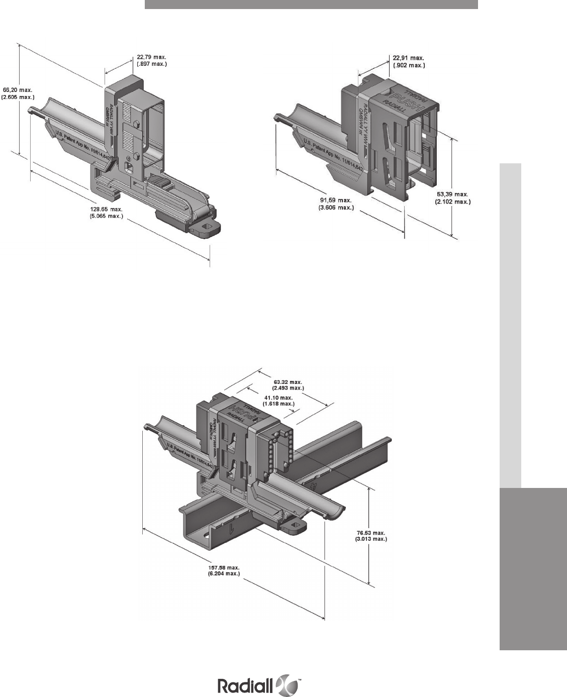
QM SERIES
INSERTS
CONTACTSCONNECTORS & ACCESSORIES
2-23
Our Most Important Connection is with You.™
Go online for data sheets & assembly instructions Visit www.radiall.com and enter the part number
Receptacle Plug
Mated Pair
QM size B shell dimensions
QMBRN: 41g
QMBZN: 48g
QMBPN: 31g
QMBWN: 38g
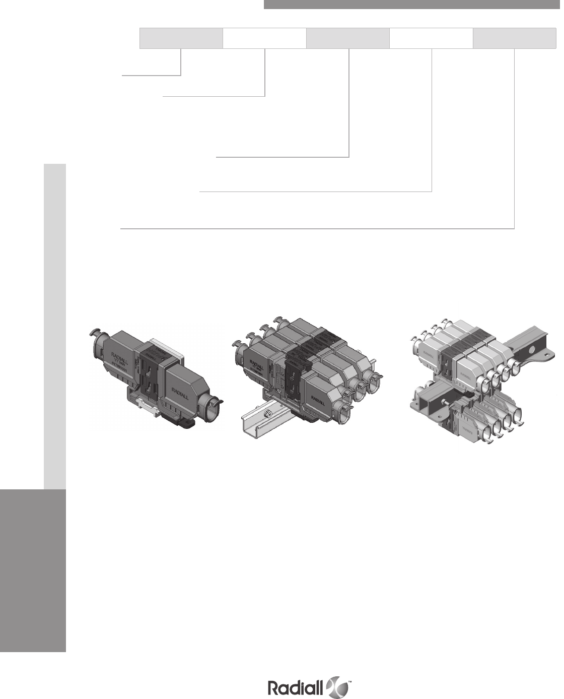
Our Most Important Connection is with You.™
QM SERIES
INSERTS
CONTACTS
CONNECTORS & ACCESSORIES
2-24 Go online for data sheets & assembly instructions Visit www.radiall.com and enter the part number
Series
Mounting Device
L: L-Bracket
U: Single sided rail
H: Double sided rail
Number of connector position
Refer to tables on pages 2-26 to 2-30 for number of connector position
Mounting device material
A: Aluminium
Finish
N: Nickel
QM U 04S A N
Double sided railSingle sided railL-Bracket
How to Order QM Mounting Device
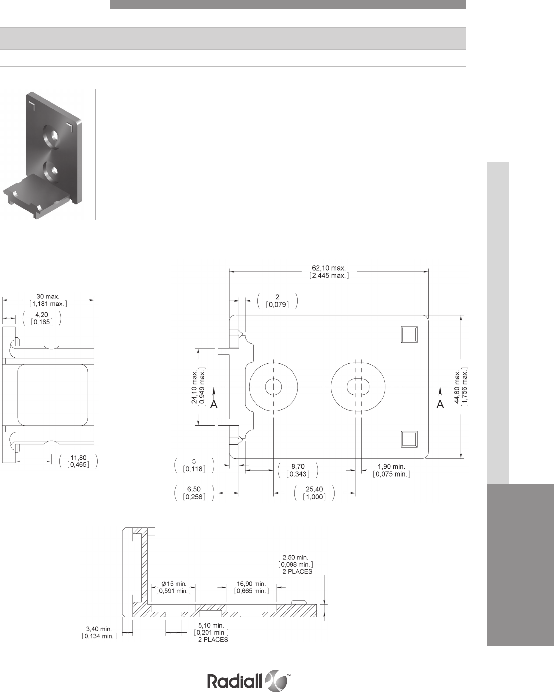
QM SERIES
INSERTS
CONTACTSCONNECTORS & ACCESSORIES
2-25
Our Most Important Connection is with You.™
Go online for data sheets & assembly instructions Visit www.radiall.com and enter the part number
Side view
Cross section
Top view
Number of
connector position
Length
mm (inch)
Weight
g (oz)
01 65.60 (2.45) 30 (1.05)
L-Bracket Dimensions
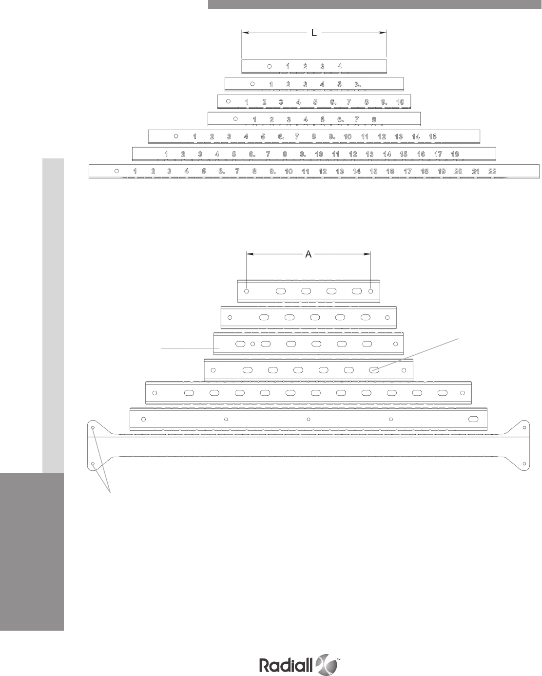
Our Most Important Connection is with You.™
QM SERIES
INSERTS
CONTACTS
CONNECTORS & ACCESSORIES
2-26 Go online for data sheets & assembly instructions Visit www.radiall.com and enter the part number
Side view
04S
06S
10S
08S
15S
04S
06S
10S
08S
15S
18
22
18
22
Fixing holes
Fixing holes
Slot
Single Sided Rails Range
Top view
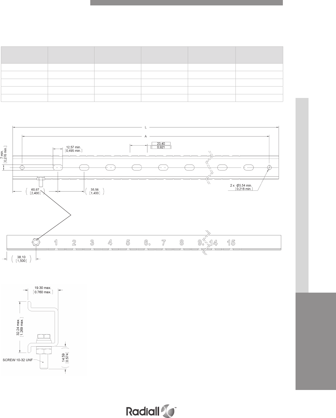
QM SERIES
INSERTS
CONTACTSCONNECTORS & ACCESSORIES
2-27
Our Most Important Connection is with You.™
Go online for data sheets & assembly instructions Visit www.radiall.com and enter the part number
These single sided rails are always delivered with slot and ground stud.
04S, 06S, 08S, 10S & 15S SINGLE SIDED RAIL
Top view
Side view
Ground stud
SINGLE SIDED RAIL
Number of
connector position
Length
mm (inch)
A distance between
fixing holes
mm (inch)
Number of slots Number of ground studs Weight
g (oz)
04S 199.60 (7.86) 175 (6.86) 4 1 85 (3)
06S 246.40 (9.70) 221 (8.70) 5 1 90 (3.20)
08S 293.10 (11.54) 268 (10.54) 6 1 100 (3.53)
10S 266.19 (10.48) 200 (7.895) 6 1 100 (3.53)
15S 457.20 (18) 432 (17) 11 1220 (7.76)
Single Sided Rails Dimensions
Cross section
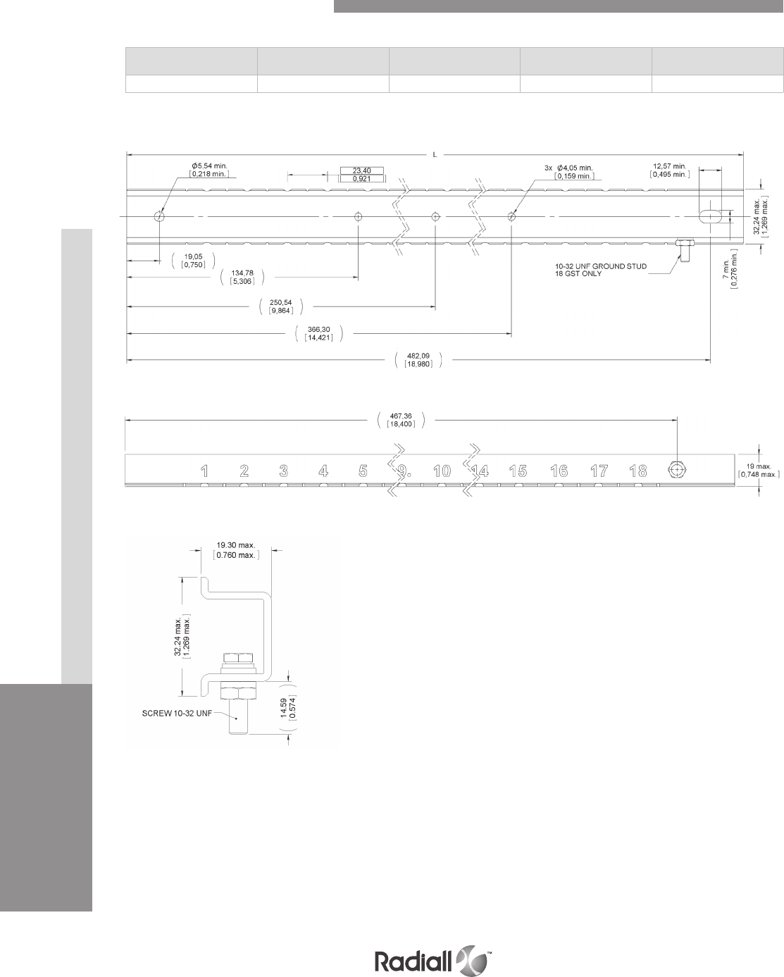
Our Most Important Connection is with You.™
QM SERIES
INSERTS
CONTACTS
CONNECTORS & ACCESSORIES
2-28 Go online for data sheets & assembly instructions Visit www.radiall.com and enter the part number
18 SINGLE SIDED RAIL
Number of
connector position
Length
mm (inch) Number of slots Number of ground studs Weight
g (oz)
18 501.40 (19.74 ) None 1170 (6)
Top view 18
Side view 18
Cross section
Single Sided Rails Dimensions
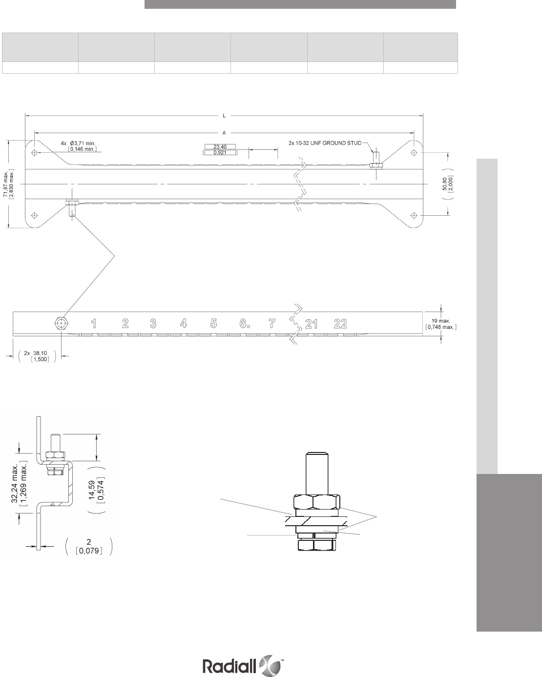
QM SERIES
INSERTS
CONTACTSCONNECTORS & ACCESSORIES
2-29
Our Most Important Connection is with You.™
Go online for data sheets & assembly instructions Visit www.radiall.com and enter the part number
Number of
connector position
Length
mm (inch)
A distance between
fixing holes
mm (inch)
Number of slots Number of ground studs Weight
g (oz)
22 620.80 (24.44) 606 (23.85) none 2230 (8.11)
22 SINGLE SIDED RAIL
TOP VIEW
Ground stud
CROSS SECTION GROUND STUD STACK-UP DETAIL
Fastener
Plain nut
Lock washer
Protective washers
Single Sided Rails Dimensions
SIDE VIEW
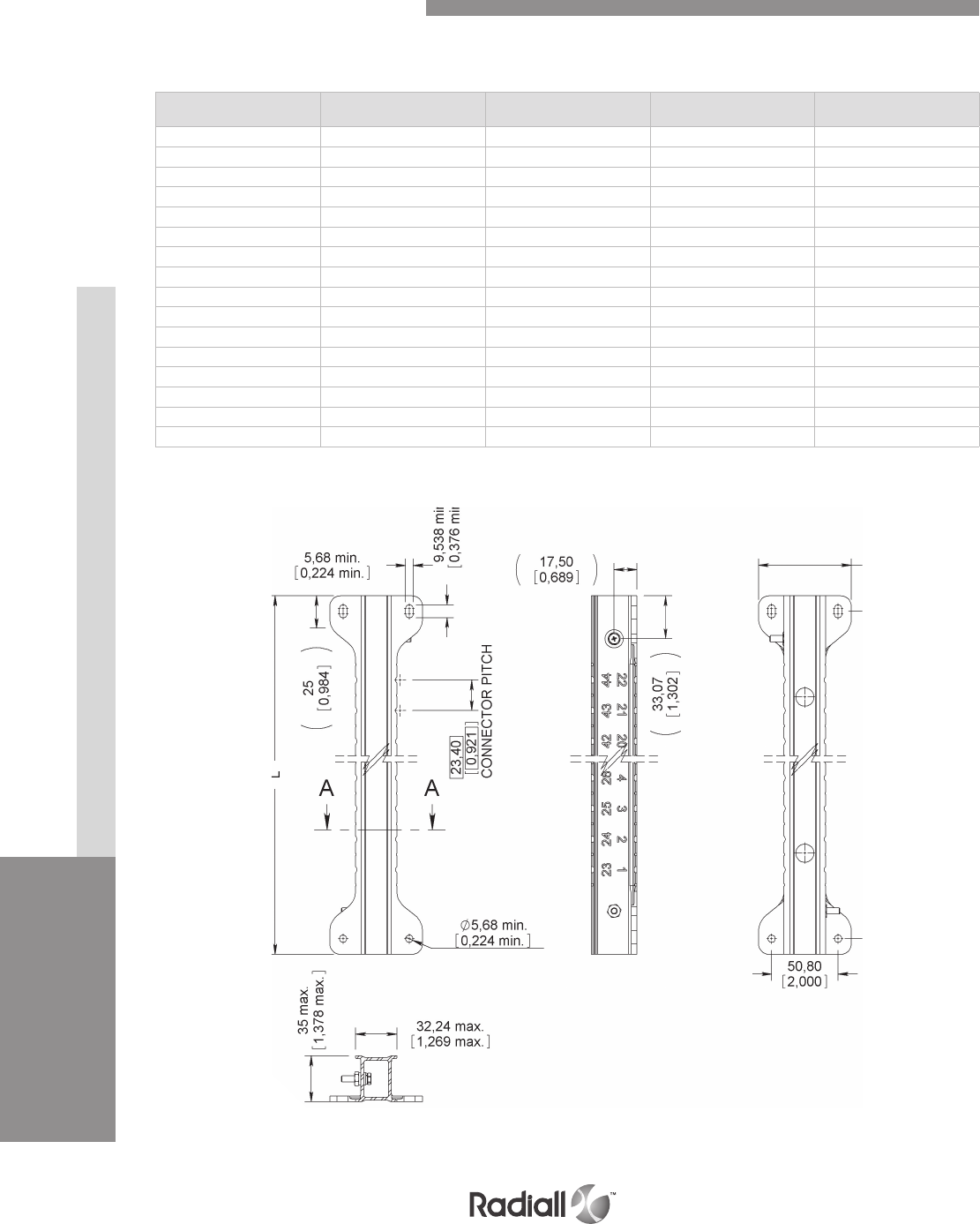
Our Most Important Connection is with You.™
QM SERIES
INSERTS
CONTACTS
CONNECTORS & ACCESSORIES
2-30 Go online for data sheets & assembly instructions Visit www.radiall.com and enter the part number
Connector pitch is 23.40 mm on every double sided rail models.
DOUBLE SIDED RAILS
Number of
connector position
Length
mm (inch)
A distance between fixing
holes mm (inch)
Number of
ground studs
Weight
g (oz)
14 270 (10.63) 246 (9.69) 2263 (9.27)
16 293 (11.55) 269 (10.61) 2279 (9.84)
18 317 (12.47) 292 (11.53) 2298 (10.51)
20 340 (13.39) 316 (12.45) 2313 (11.04)
22 363 (14.31) 340 (13.37) 2332 (11.71)
24 387 (15.23) 363 (14.29) 2351 (12.38)
26 410 (16.15) 386 (15.21) 2370 (13.05)
28 434 (17.07) 410 (16.13) 2388 (13.68)
30 457 (18) 433 (17.06) 2405 (14.28)
32 480 (18.92) 457 (17.98) 2424 (14.95)
34 504 (19.84) 480 (18.90) 2443 (15.62)
36 527 (20.76) 503 (19.82) 2462 (16.29)
38 551 (21.68) 527 (20.74) 2481 (16.96)
40 574 (22.60) 550 (21.66) 2499 (17.60)
42 597 (23.52) 574 (22.58) 2519 (18.30)
44 620 (24.44) 597 (23.21) 2540 (19.04)
Double Sided Rails Dimensions
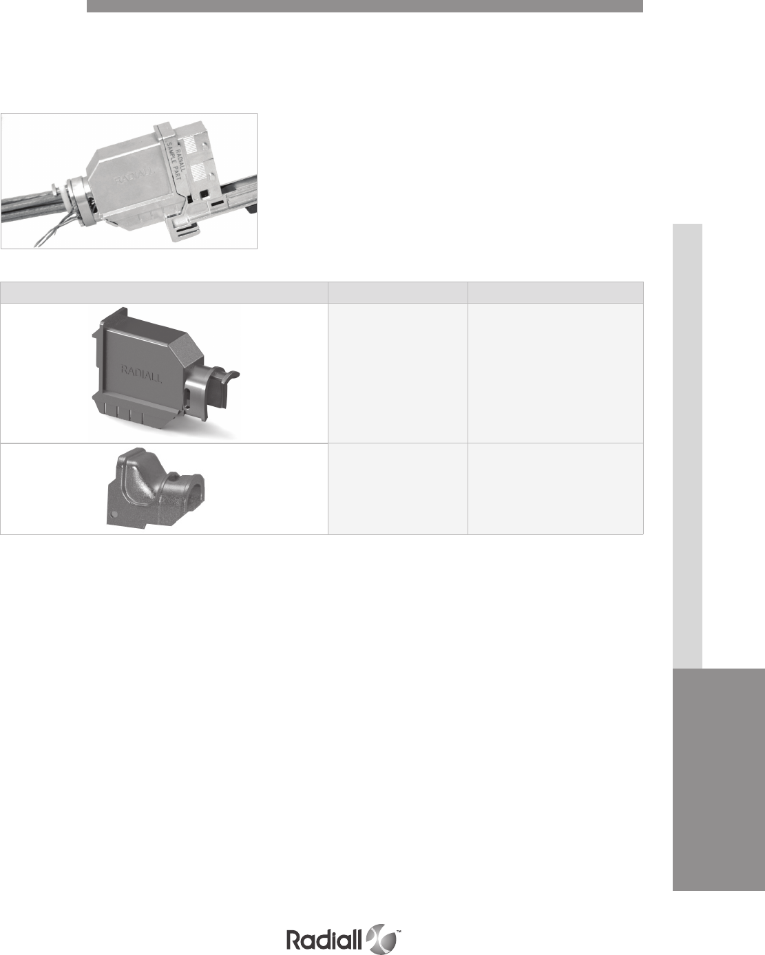
QM SERIES
INSERTS
CONTACTSCONNECTORS & ACCESSORIES
2-31
Our Most Important Connection is with You.™
Go online for data sheets & assembly instructions Visit www.radiall.com and enter the part number
Accessories
QM connectors can be equipped with backshells to provide complete shielding.
Backshells are compatible with plug and receptacle side. They provide EMI-RFI shielding specially
needed in aircrafts with a composite architecture. Made of composite and easy to install as they require
no specific tools, they help in combining cost saving and high performances.
Backshell Part number Description
617991 001 QM size B EMI backshell
617 924 015 QM size A EMI backshell
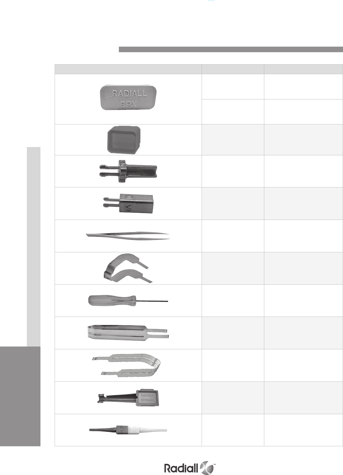
Our Most Important Connection is with You.™
QM SERIES
INSERTS
CONTACTS
CONNECTORS & ACCESSORIES
2-32 Go online for data sheets & assembly instructions Visit www.radiall.com and enter the part number
Part number Description
617 954 041 Dust cap for QM size B plug
617 954 042 Dust cap for QM size B receptacle
617 954 055 Dust cap for QM size A plug and
receptacle
617980 024 Polarization key pin
617980 025 Polarization key socket
282668 001 Pliers for polarizing post and key
282521 004 Right angle insert extraction tool
F780855 000 Hexagonal key 5/64 inch(2mm)/flats
for sleeve holder removal
282521 005 Insert extraction tool
for EPXA insert
282 521 002 Insert extraction tool for EPXB insert
617954 020 Plastic box to protect wired inserts
during handling
282515
Plastic insert extraction tool for
LuxCis® termini
(MIL M81969/14-03)
Spare Parts and Tools
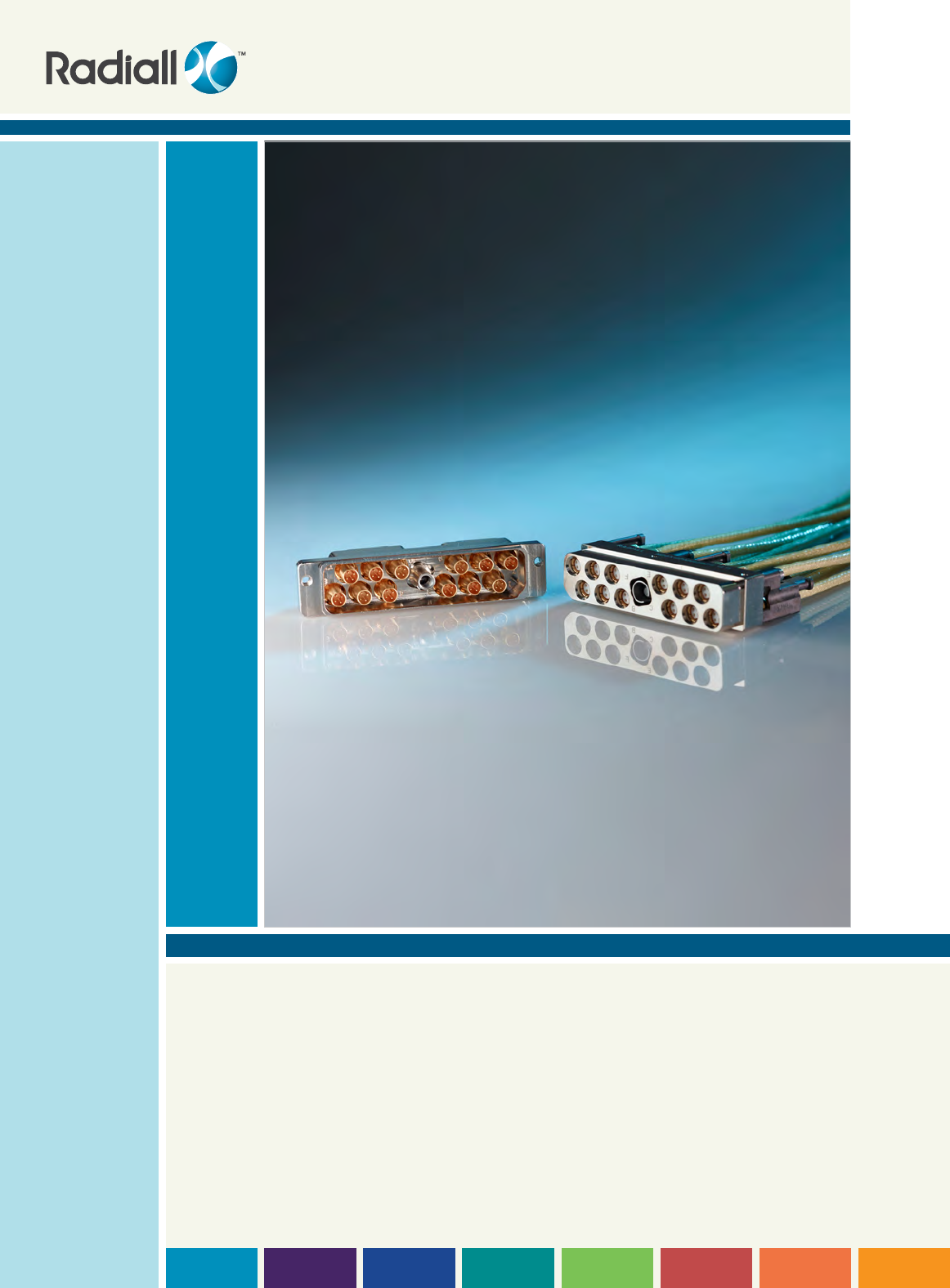
HDQX Series
SECTION 3

Our Most Important Connection is with You.™

SECTION 3 TABLE OF CONTENTS
3-3
Our Most Important Connection is with You.™
Go online for data sheets & assembly instructions Visit www.radiall.com and enter the part number
Introduction ��������������������������������������������������������������������������������������������������������������������� 3-4
Applications ��������������������������������������������������������������������������������������������������������������������� 3-4
Features ������������������������������������������������������������������������������������������������������������������������� 3-5
Technical characteristics of shells �������������������������������������������������������������������������������������������� 3-6
Crimp contacts ������������������������������������������������������������������������������������������������������������������ 3-7
PC tail contacts ����������������������������������������������������������������������������������������������������������������� 3-7
Product overview ��������������������������������������������������������������������������������������������������������������� 3-8
How to order HDQX connectors ������������������������������������������������������������������������������������������������ 3-9
Contacts termination ���������������������������������������������������������������������������������������������������������� 3-10
Shell mounting ���������������������������������������������������������������������������������������������������������������� 3-10
Dimensions ������������������������������������������������������������������������������������������������������������������� 3-11
Panel cut out������������������������������������������������������������������������������������������������������������������� 3-12
Polarization code ������������������������������������������������������������������������������������������������������������� 3-14
Accessories and tools �������������������������������������������������������������������������������������������������������� 3-15
Contents
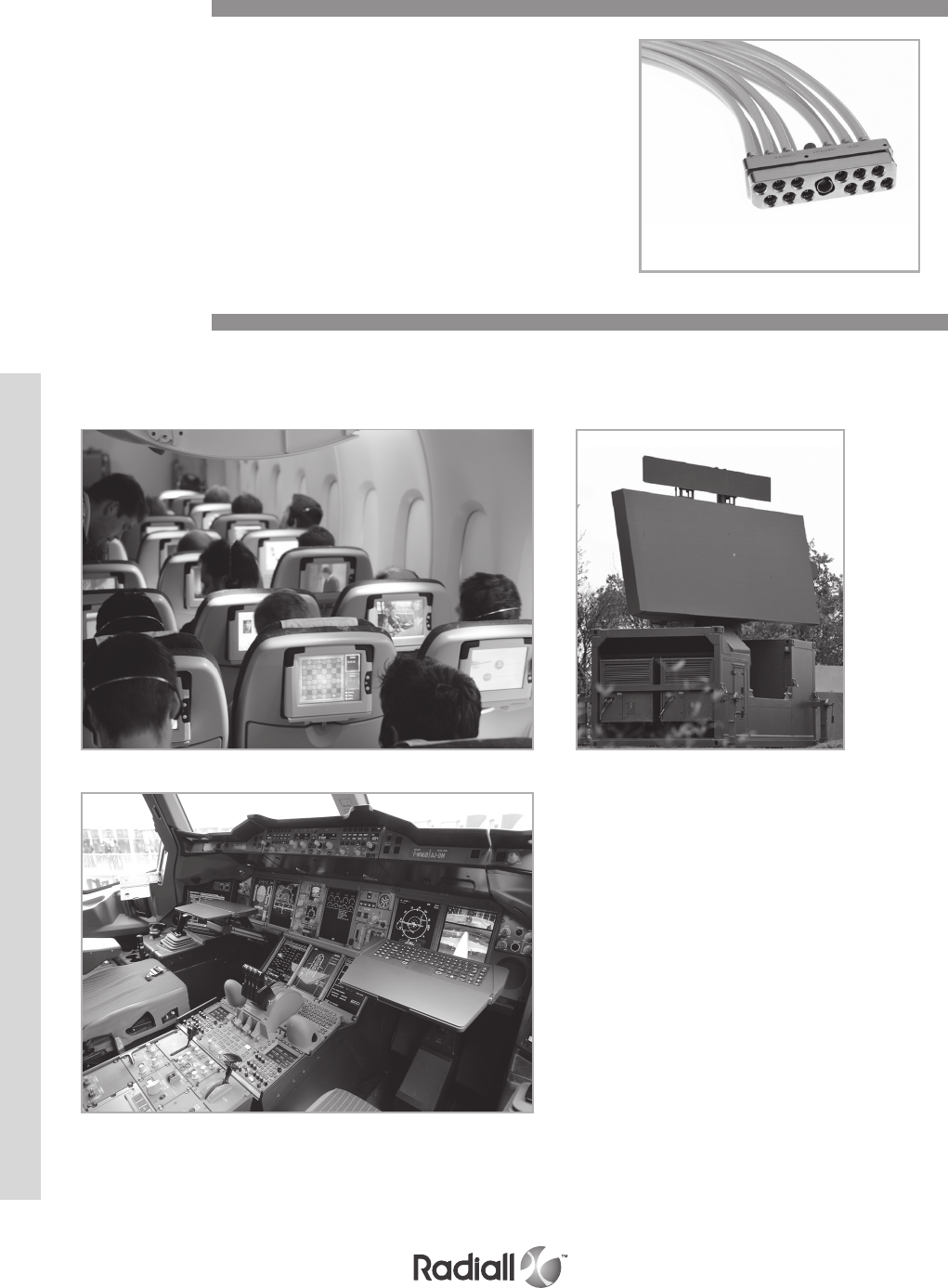
HDQX SERIES
3-4
Our Most Important Connection is with You.™
Go online for data sheets & assembly instructions. Visit www.radiall.com and enter the part number
Radiall introduces the new HDQX connector series, specially
designed for the transmission of Ethernet and RF high
speed signals required in harsh environment applications�
HDQX connectors combine both the compact and
rugged qualities necessary for high reliability and signal
integrity in aerospace and military environments�
The HDQX range offers Cable-to-Cable and Cable-to-PCB
solutions� Offering twelve size 8 cavities in a high-density
rectangular shell, the space saving HDQX accepts Quadrax
and BMA RF contacts, as well as twinax and triaxial contacts�
© AIRBUS S.A.S 2007 _ photos by e’m company / H. GOUSSÉ
Typical applications for the HDQX connectors include data networks, in-flight entertainment
systems, video control centers, and naval and military vehicle communications�
Introduction
Applications
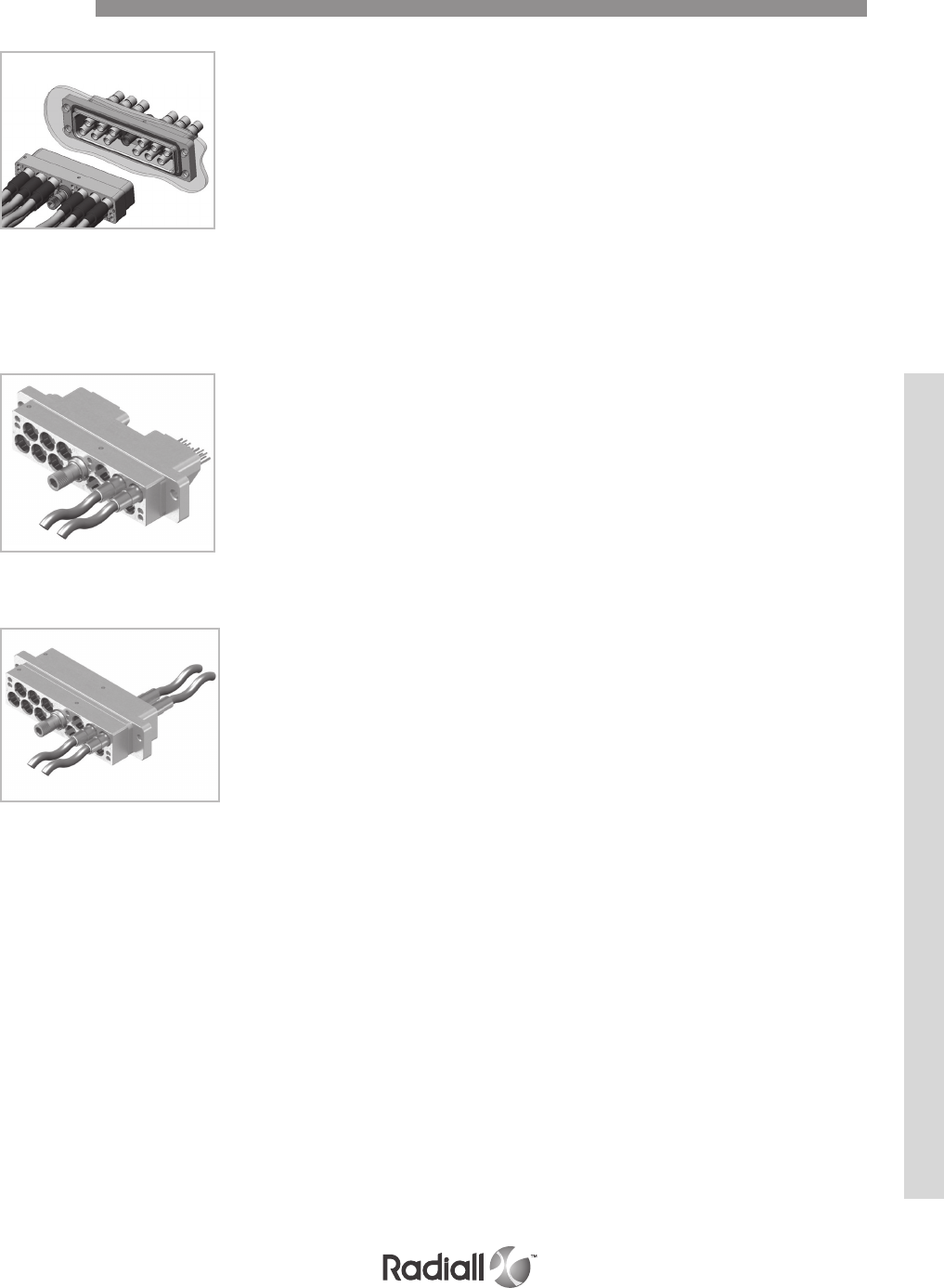
HDQX SERIES
3-5
Our Most Important Connection is with You.™
Go online for data sheets & assembly instructions Visit www.radiall.com and enter the part number
HDQX CONNECTOR BENEFITS:
- High-density solution for size 8 cavities using standard ARINC 600
Quadrax contacts and size 8 BMA RF coax, triax, and twinax contacts
- Space-saving connector for limited space applications
- Rectangular connector is stackable
- Lightweight composite strain relief
- Simple and secure connection with a central locking device
- Contacts grounded to the shell with extremely high
electrical continuity
AVAILABLE HDQX RANGE CONNECTORS:
- Class N – Non-environmental plug and receptacle
- Class E – Environmental plug and receptacle
(connector sealed on the electrical line)
- Class P – Panel sealed receptacle
(feed-through sealed connector)
MAIN FEATURES ARE:
- 12 contacts cavities
- Grounded size 8 standard cavities (ARINC 600 type)
- Cable-to-cable and cable-to-PCB application
- RoHS compliant
- 12 keying formatting possibilities positions
- 1 central position jacknut / Jackscrew
- Uses standard insertion/extraction tool
- User Manual # MIIN1700002 is available
Class P connector pair
Cable to PCB application
Cable to cable application
Features

HDQX SERIES
3-6
Our Most Important Connection is with You.™
Go online for data sheets & assembly instructions. Visit www.radiall.com and enter the part number
- Shell to shell conductivity: 2�5 mΩ (level reached during initial and after testing as per EN2591-205)�
- Contact-to-shell conductivity: maximum of 10 mΩ
(level reached during initial and after environmental testing)
- Lightning strike:
- Pin injection: 1600V 320A as per RTCA DO160 (§22�5�1)
- Current pulse: 3kA as per EN2591-214
- DWV at sea level:
- 1000Vrms between outer body and signal contacts as per EN2591-207, Method C
- 1000Vrms between signal contacts
- DWV altitude (70,000 feet): 125Vrms for the quadrax contacts as per ARINC 600
- Mating/Unmating: 100 cycles
- Impact test: 8 drops at 1�20m as per EN2591-613
- Bending moment (applied to accessories): 100N as per EN2591-404
- Mechanical axial strength (applied to accessories): 100N as per EN2591-420
Series Material
Vibration Shock
For 8 hrs on each of the 3 axis/
interruption<1 μs EN2591-403
EIA 364-28
3 shocks on each axis
EN2591-402 EIA 364-27
HDQX Aluminium
Acceleration 16�9g
(Method B figure 2 table 1
Level E)
Shock amplitude 50g /duration 11ms
VIBRATION & SHOCKS
Technical Characteristics of Shells
- Temperature range: -65°C / +150°C (-85°F / +302°F), 5 cycles as per EN2591-305
- Temperature life: 1000 hours at 150°C (+302°F) as per EN2591-301 Method B
- Salt spray: 96 hours as per EN2591-307
- Sealing: altitude immersion 50,000 feet as per EN2591-314
- Sand & dust: wind velocity 3�5 ±0�5 ms as per EN2591-308
- Mould growth: during 28 days, growth 0 as per EN2591-306 Method A
- Fluid immersion: kerosene, phosphate base, mineral base, polyolester, solvent, detergent,
aircraft deicers, heptafluoropropane, pentafluoroethane, radar coolant as per EN3909
- Magnetic permeability: 2µ as per EN2591-513
OTHER CHARACTERISTICS
MECHANICAL CHARACTERISTICS
ELECTRICAL CHARACTERISTICS
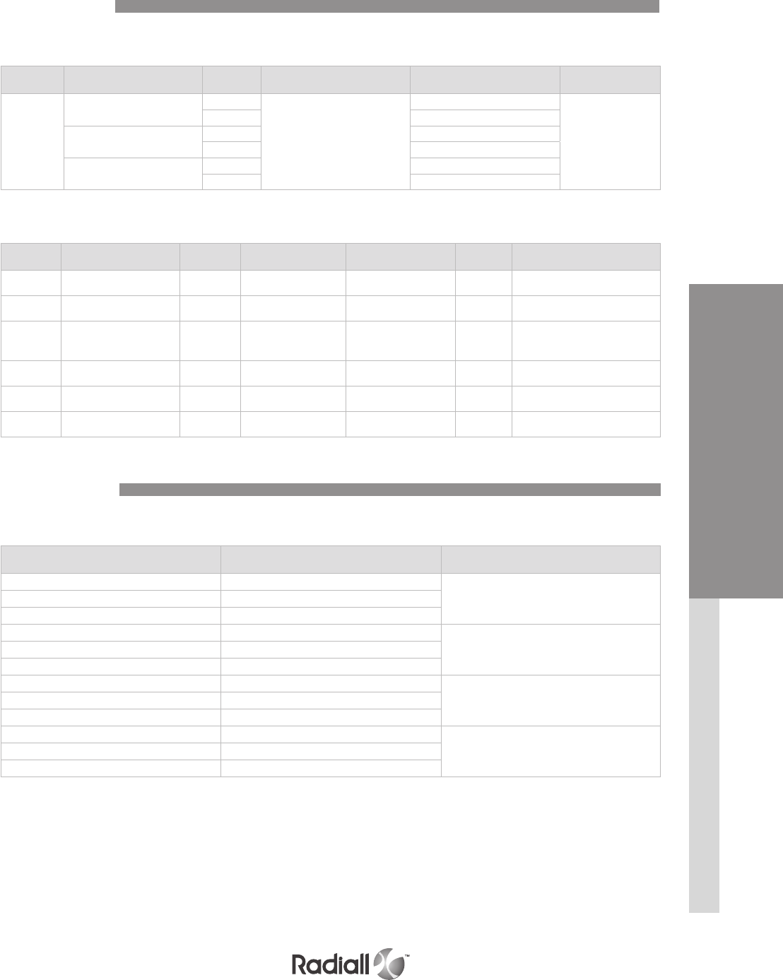
HDQX SERIES
CONNECTORS & ACCESSORIES CONTACTS
3-7
Our Most Important Connection is with You.™
Go online for data sheets & assembly instructions Visit www.radiall.com and enter the part number
Contact size Cable type Type Environmental
Part number
Non-environmental
Part number Ins / ext tool in metal
8
Ethernet cable
ABS0972 & ABS1503
Pin
Consult Radiall
620175010
282549001
Socket 620075010
Tensolite
NF24Q100
Pin 620175050
Socket 620075050
Tensolite
NF26Q100 - JSF Y18
Pin 620175021
Socket 620075021
Standardized ARINC 600 Quadrax contacts are available with HDQX series�
Extraction tool 282549001 is used for size 8 BMA contacts�
Contact size Cable type Connector
Type
Non-environmental
Part number Frequency range Max VSWR Insertion loss
8 SHF5 - SHF5M(See note 1) Pin 617171010 DC-18 GHz 1�35 0�13 dB at max frequency
(18 GHz)
8 RG142 Pin 617171020 DC-12,4 GHz 1�35 0�11 dB at max frequency
(12�4 GHz)
8
SHF2�4M(See note 1) / UT�085
Harbour SS405
Times Tflex405
Pin 617171030 DC-18 GHz 1�35 0�13 dB at max frequency
(18 GHz)
8SHF5 - SHF5M(See note 1) Socket 617071010 DC-18 GHz 1�35 0�13 dB at max frequency
(18 GHz)
8 RG142 Socket 617071020 DC-12,4 GHz 1�35 0�11 dB at max frequency
(12�4 GHz)
8SHF3(See note 1) Socket 617071040 DC-18 GHz 1�35 0�13 dB at max frequency
(18 GHz)
NOTES:
(1) BMA which have to accommodate SHF cable requires a wiring done by Radiall, please, contact Radiall for information
(2) Minimum length corresponds to straight PC tail length protruding from HDQX cavity
Part Number Contact termination Minimum length
in mm (inch)(See note 2)
620176009 YA
2�80 (�110)620176016 ZA
620176509 RA
620176008 Y
5�65 (�222)620176010 Z
620176508 R
620176011 YB
8�50 (�334)620176012 ZB
620176511 RB
620176013 YC
11�90 (�469)620176014 ZC
620176513 RC
SIZE 8 QUADRAX PIN CONTACTS
Crimp Contacts
PC Tail Contacts
BMA CONTACTS
QUADRAX CONTACTS
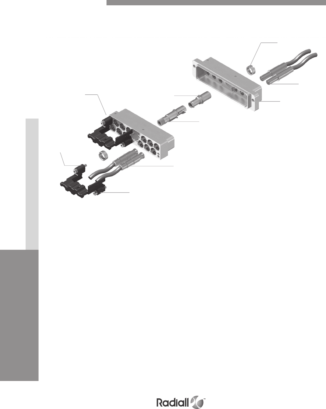
HDQX SERIES
CONNECTORS & ACCESSORIES CONTACTS
3-8
Our Most Important Connection is with You.™
Go online for data sheets & assembly instructions Visit www.radiall.com and enter the part number
Detailed view of the various parts of HDQX connector:
Jacknut
captive
screw
Receptacle
shell
Pin
contact
Jackscrew
Cylindrical nut
Plug shell
Socket
contact
Strain relief
Product Overview
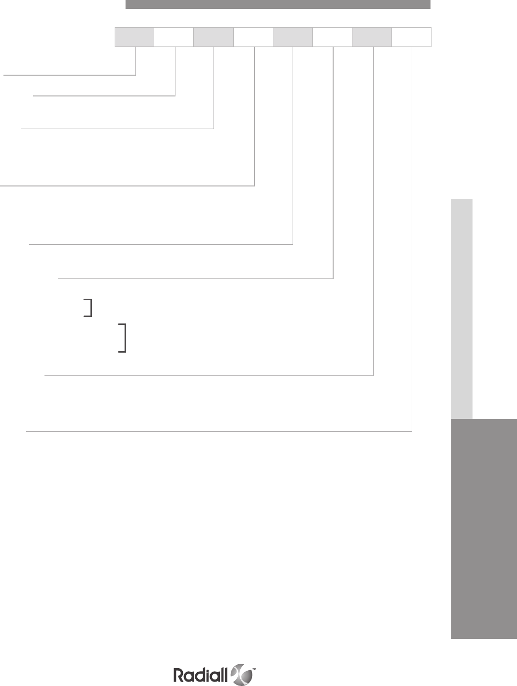
HDQX SERIES
CONNECTORS & ACCESSORIES CONTACTS
3-9
Our Most Important Connection is with You.™
Go online for data sheets & assembly instructions. Visit www.radiall.com and enter the part number.
Series
Connector size
12: 12 size 8 cavities
Shell style
P: Plug for RR/RR (rear release / rear removable) contacts
R: Receptacle for RR/RR (rear release / rear removable) contacts
F: Receptacle for FR/FR (front release / front removable) contacts
Class
E: Environmental (upon request only)
N: Non-environmental
P: Panel sealing, receptacle only (upon request only)
Shell plating
N: Nickel
Contact termination
X: No contacts
Qx: Crimp Quadrax contacts
Cx: Crimp BMA contacts(1)
Yx: Gold PC tail Quadrax contacts
Zx: Tin lead PC tail Quadrax contacts
Rx: Pure tin PC tail Quadrax contacts
Shell mounting
00: Flangeless plug
00: 2 self-locking threads for 6-32 UNC 2A screws for receptacle
01: 4 self-locking threads for 6-32 UNC 2A screws for receptacle
Polarization
Without: No polarization system provided
Polarization: See page 3-13 for codes
HDQX 12 F N N YA 00 12
NOTE:
(1) BMA contacts are not available with class E and P
How to Order HDQX Connectors
see table 1 page 3-10
see table 2 page 3-10
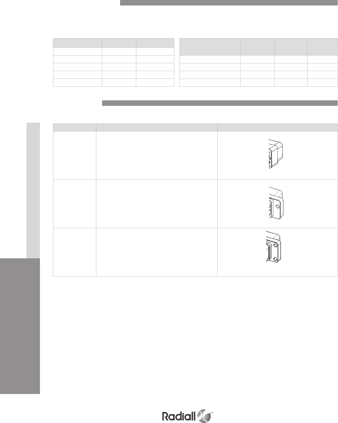
HDQX SERIES
CONNECTORS & ACCESSORIES CONTACTS
3-10
Our Most Important Connection is with You.™
Go online for data sheets & assembly instructions Visit www.radiall.com and enter the part number
TABLE 1:
Crimped contact termination
for RR/RR receptacle and plug
TABLE 2:
PC-tail contact termination
for FR/FR receptacle
Cable Quadrax BMA
ABS1503KD24 Q1 -
NF24Q100 Q2 -
JSFY18 Q3 -
RG142 -C1
UT 0�085 -C2
Minimum
length mm (inch) Gold Tin-lead Pure tin
2�80 (�110) YA ZA RA
5�65 (�222) Y Z R
8�50 (�334) YB ZB RB
11�90 (�469) YC ZC RC
Code Detail
00 Flangeless plug (no fixing system)
00 Rear panel mounting receptacle:
2 self-locking threads for 6-32 UNC 2A screws
01 Rear panel mounting receptacle:
4 self-locking threads for 6-32 UNC 2A screws
Both shell mounting 00 and 01 are available with RR/RR and FR/FR receptacle�
Shell Mounting
Contacts Termination

HDQX SERIES
CONNECTORS & ACCESSORIES CONTACTS
3-11
Our Most Important Connection is with You.™
Go online for data sheets & assembly instructions. Visit www.radiall.com and enter the part number.
RECEPTACLE PLUG
Dimensions
not applicable
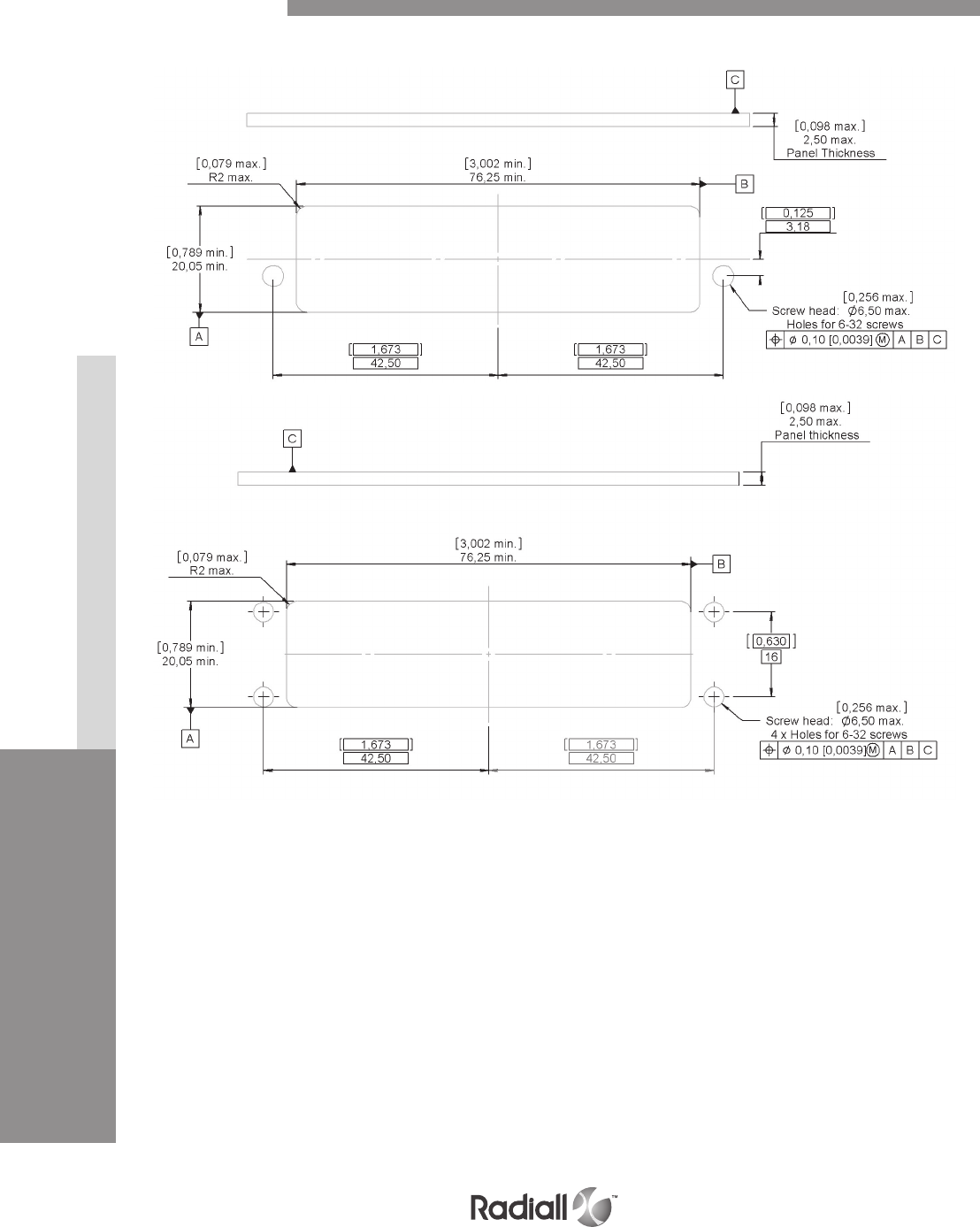
HDQX SERIES
CONNECTORS & ACCESSORIES CONTACTS
3-12
Our Most Important Connection is with You.™
Go online for data sheets & assembly instructions Visit www.radiall.com and enter the part number
RECEPTACLE
Panel Cut Out
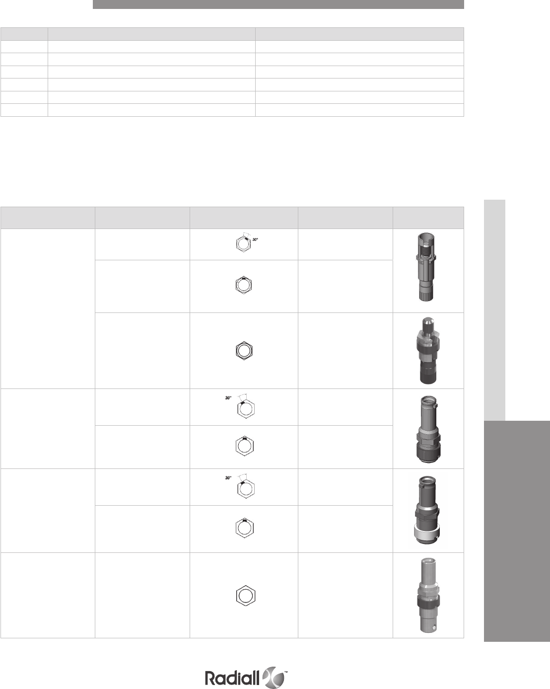
HDQX SERIES
CONNECTORS & ACCESSORIES CONTACTS
3-13
Our Most Important Connection is with You.™
Go online for data sheets & assembly instructions. Visit www.radiall.com and enter the part number.
Code Device Device delivered
12 Jackscrew, A to F Unassembled
13 Jackscrew, N to Z Unassembled
22 Jacknut, A to F Unassembled
23 Jacknut, N to Z Unassembled
1A Jackscrew, position A to Z Assembled
2A Jacknut, position A to Z Assembled
Designation Polarizing
positions Coding device Part number
Jackscrew
A to F 617612801
N to Z 617612803
Universal 617612806
Jacknut for front
release receptacle
A to F 617612805
N to Z 617612804
Jacknut for rear
release receptacle
A to F 617612800
N to Z 617612802
Jacknut Universal 617612807
In the standard version, the jackscrew is mounted on the plug shell and the jack nut is mounted on the
receptacle shell�
There are 2 sets of jackscrews and jacknuts� Each set provides 6 polarizing positions A, B, C, D, E, and F
and the second set provides polarizing positions N, R, W, X, Y and Z� The difference between the 2 sets is
accomplished using an indexing point shown below in the drawings:
HDQX JACKSCREW & JACKNUT
Polarization Code
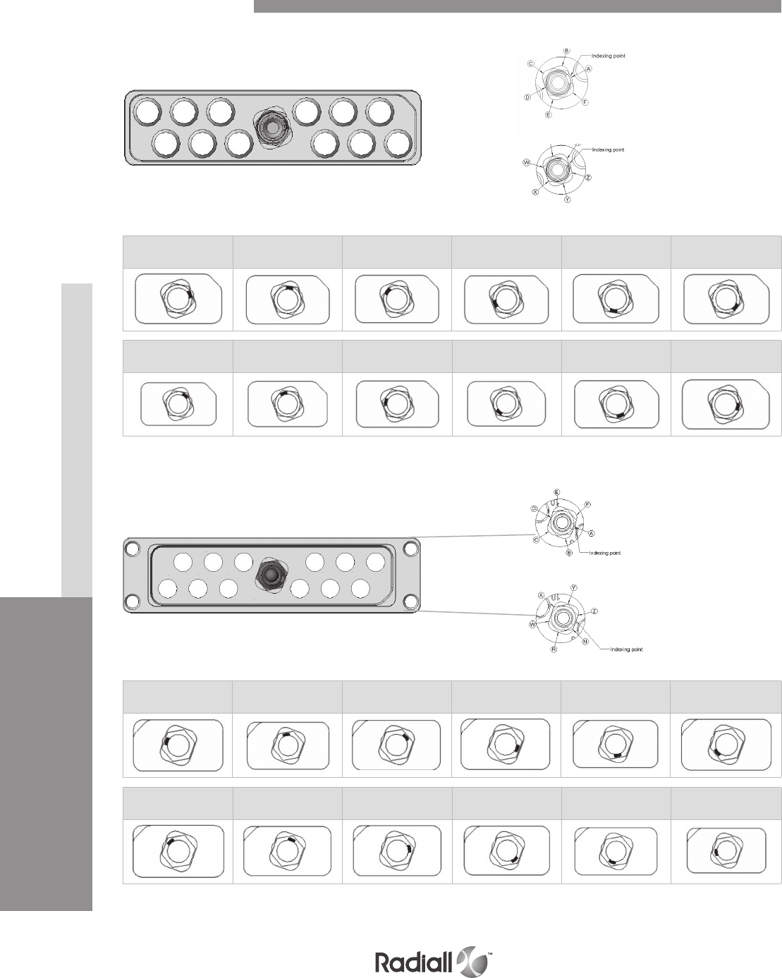
HDQX SERIES
CONNECTORS & ACCESSORIES CONTACTS
3-14
Our Most Important Connection is with You.™
Go online for data sheets & assembly instructions Visit www.radiall.com and enter the part number
A B C D E F
N R W X Y Z
MATING FACE SHOWN
Polarization Code
N to Z
A to F
PLUG SHELL
A B C D E F
N R W X Y Z
MATING FACE SHOWN
A to F
N to Z
RECEPTACLE SHELL
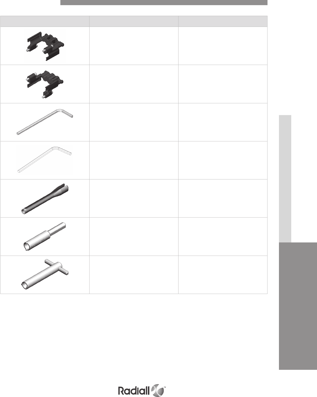
HDQX SERIES
CONNECTORS & ACCESSORIES CONTACTS
3-15
Our Most Important Connection is with You.™
Go online for data sheets & assembly instructions. Visit www.radiall.com and enter the part number.
Part number Description
617922024 Strain relief for plug
assembly torque 0�55 ±0�05 Nm
617922026 Strain relief for receptacle
assembly torque 0�55 ±0�05 Nm
282666001 Connector locking: Allen wrench (9/64 inch)
282666002 Strain relief locking: Allen wrench (5/64 inch)
282549001 Extraction tool (for Quadrax and BMA contacts)
282664 1/4 inch hex� screwdriver bit to affix the
nut of the jackscrew or the jacknut
282665 Spigot wrench to affix the nut of
the jackscrew or the jacknut
Accesories and Tools

HDQX SERIES
3-16
Our Most Important Connection is with You.™
Go online for data sheets & assembly instructions. Visit www.radiall.com and enter the part number
Notes
NSX - BPX Series
SECTION 4
Arinc 600

Our Most Important Connection is with You.™

SECTION 4 TABLE OF CONTENTS
4-3
Our Most Important Connection is with You.™
Go online for data sheets & assembly instructions. Visit www.radiall.com and enter the part number.
NSX - ARINC
Introduction ....................................................4-4 to 4-5
Application ..................................................................4-6
Characteristics:
- Technical characteristics ........................................ 4-7
- Electrical ................................................................. 4-7
- Mechanical & Environmental .................................. 4-7
- Masses ..................................................................... 4-8
EMI/RFI performances .......................................... 4-9
- Material ..................................................................... 4-9
- Characteristics ........................................................ 4-9
Product overview ................................................... 4-10
How to order ............................................................ 4-11
- Contact arrangement ................................. 4-12 to 4-21
- Insert combination code ............................. 4-22 to 4-28
- Modification code ........................................ 4-29 to 4-30
- Polarization code .................................................... 4-31
- Polarization code table ............................. 4-32 to 4-33
Contacts:
- Signal, power and ground
contacts crimps termination .................... 4-34 to 4-36
- Chromel contacts – crimp termination .................4-37
- Alumel contacts – crimp termination .................... 4-38
- Coaxial contacts .........................................4-39 to 4-51
- Concentric twinax contacts ...................................4-52
- Quadrax contacts ....................................................4-53
- LuxCis® contacts ...................................... 4-54 to 4-56
- NSX E/N/H/C – rear removable contacts .......... 4-57
Contents
How to order NSX F/G/K .........................................4-58
NSX F/G/K Contacts ................................... 4-59 to 4-62
Dimensions ................................................. 4-63 to 4-77
Panel cut out ................................................4-78 to 4-79
Tools ............................................................. 4-80 to 4-81
Accessories ................................................ 4-82 to 4-89
NSX – SINGLE SHELL
Introduction ...............................................................4-90
Material ......................................................................4-90
How to order ............................................................. 4-91
Installation ................................................... 4-93 to 4-93
Dimensions ...................................................4-94 to 4-95
Panel cut out .............................................................. 4-96
EMI/RFI shell dimension ........................................ 4-97
BPX
Introduction ..............................................................4-98
Characteristics:
- Electrical ................................................................ 4-98
- Mechanical & Environmental ................................4-99
- Materials ................................................................4-99
How to order ........................................................... 4-100
Insert combination code .........................................4-101
Contact .....................................................................4-101
Accessories .............................................. 4-102 to 4-104
Dimensions ................................................4-105 to 4-110
Panel cut out .............................................. 4-111 to 4-112

NSX AND BPX MULTICONTACT CONNECTORS
NSX series (defined by ARINC 600 specification) and BPX series
(defined by Boeing S280W551 specification) are multipin rack and panel connectors
used to connect high performance aeronautical equipment.
Items in this catalog are covered by French and foreign Patents and/or Patents pending.
These two series manufactured by Radiall show the following characteristics:
- High contact density
- Wide range of contact types and arrangement
- Numerous shell polarization possibilities which give maximum security when mating
the equipment in the rack
- Low mating forces
- Separation of power and signal contacts
- EMI/RFI shielding option provided by shell to shell conductivity
Major aircraft manufacturers and equipment manufacturers have been entrusting Radiall for many
years using NSX and BPX series.
NSX SERIE (ARINC 600 STANDARD)
RADIALL NSX series offers the following versions included a new cost effective solution:
Connectors for rear removable contacts:
- NSX N: Plug and receptacle connectors.
Non environmental version, inserts without grommet and
compound, plugs without groove and O-ring.
- NSX C: Plug and receptacle connectors.
Non environmental version, inserts with grommet but without
compound, plugs without groove and O-ring.
- NSX E: Plug and receptacle connectors.
Environmental version, inserts with grommet and
compound, plugs with groove and O-ring.
- NSX H: Plug connector only.
Environmental version, inserts with grommet and
compound, plugs without groove and O-ring.
Connectors for front removable contacts:
- NSX F: Receptacle connectors only.
Only signal contacts are Front release/Front Removable (FR/
FR), others will be Rear Release/Rear Removable (RR/RR). Non
environmental version, inserts without grommet and compound.
- NSX G: Receptacle connectors only.
Signal, power, coax, triax and quadrax contacts are FR/FR.
Non environmental version, inserts without grommet and compound.
- NSX K: New cost effective solution. 100% RoHS compliant for shell plating selection F and S.
Receptacle connectors only.
Inserts fully completed with harpooned size 22 contacts
Non environmental version
As an option, EMI/RFI features are available to get shell to shell conductivity.
Introduction
NSX - BPX SERIES
4-4
Our Most Important Connection is with You.™
Go online for data sheets & assembly instructions. Visit www.radiall.com and enter the part number.
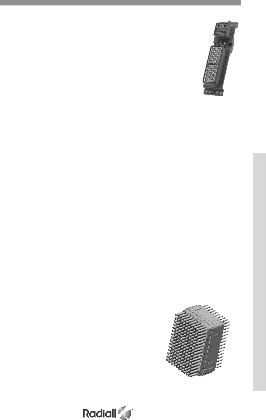
Introduction
INSERTS
Environmental inserts have a wire sealing grommet on the rear face and compound
between insert and shell. The different kinds of inserts available are:
- Insert for rear release rear removable contacts (blue colored on the terminating face).
- Insert for front release front removable contacts (red colored on the mating face).
- Insert for front release rear removable contacts (yellow colored on the mating face).
CONTACTS
A whole range of crimp or PC tail contacts are available with NSX connectors: signal, coax, triax,
quadrax or fiber optic contacts. Signal and power contacts were designed to be low insertion force
contacts so that they are perfectly orientated into the cavities and contacts are not damaged when
insertion is made. Front release and rear release inserts use contact retention system (clips) which
meets the ARINC 600 contact retention requirements. This system allows contacts to be removed from
the insert using an extraction tool
NEW COST EFFECTIVE SOLUTION
Radiall is constantly looking for cost saving solutions to answer our customers’ expectations.
Based on this concept, Radiall proudly introduces:
Inserts with harpooned contacts
Discover the new class K available for front removable contacts. They show the following
features and benefits:
- Improved pricing stability and reduced dependence on fluctuating gold prices
- Lightweight solution as insert is one piece
- 100% intermateable with any ARINC 600 plug
- 100% backwards compatibility with existing PCB and PGA connectors
- RoHS compliant
- Fully qualified under Arinc 600 specification requirements
Selective plating contacts
A brand new range of PC tail contacts with gold selective plating is now
available. They offer the following features and benefits:
- Significant reduction of cost of ownership
- N- more dependence t- gold rate fluctuation
- N- change in the contact integration process
Specifications:
- Same contact design as full plated version
- Contact interface gold plated with 1.27µm
- No impact on PCB design
- Product qualification is available upon request
SHELL
RADIALL NSX series offers three metallic shell sizes fitted with polarization hardware
offering 216 polarizing possibilities.
NSX shells answer all requirements with three different platings, all compliant with ARINC
600 standard: alodine, nickel, RoHS.
The plug shell is fitted with inserts for signal (size 22) pin contacts, coax, triax and
quadrax socket contacts. The receptacle shell is fitted with inserts for signal socket
contacts, coax, triax and quadrax pin contacts.
NSX - BPX SERIES
4-5
Our Most Important Connection is with You.™
Go online for data sheets & assembly instructions. Visit www.radiall.com and enter the part number.
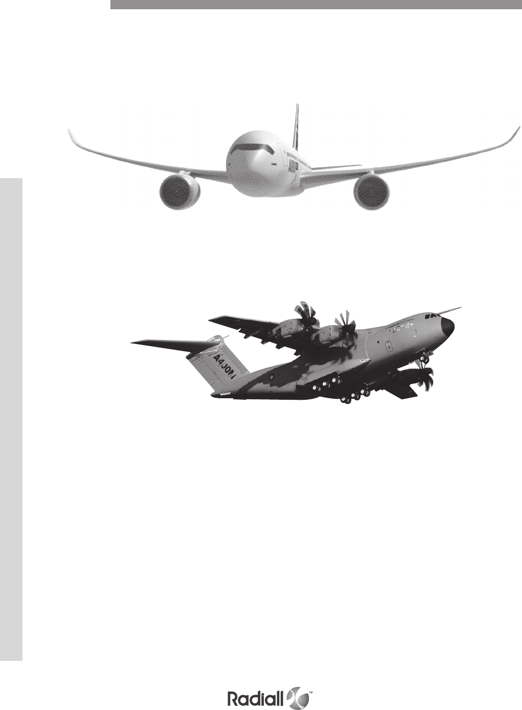
These connectors are mostly used to connect high performance aeronautical equipment.
Most of the NSX connectors are used in the main avionics bay on commercial airplanes.
Electronic functions are found in an LRU (Line Replaceable Unit).
Refer to Arinc 600 document for more information.
Application
NSX SERIES
4-6
Our Most Important Connection is with You.™
Go online for data sheets & assembly instructions. Visit www.radiall.com and enter the part number.
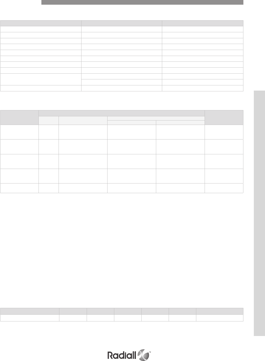
TECHNICAL CHARACTERISTICS
Description Material Plating
Shell Aluminum alloy Chromatation or nickel
Inserts Thermosetting or thermoplastic /
Metallic inserts Aluminum alloy Nickel
O-ring & grommet Fluorosilicone /
Contacts Copper alloy Gold over nickel
Retention clip Copper alloy /
Insert retention plate Aluinum alloy Blue anodized or nickel
Polarization posts and keys retention plate Aluminum alloy Chromatation or nickel
Screws vashers and clinch-nuts Stainless steel /
Steel Cadmium yellow chromate
Polarization posts and keys Zinc alloy Nickel
ELECTRICAL CHARACTERISTICS
Contact size
Wire
Max current (A)
AWG Cross section (mm2)Outside Dia. mm (inches)
min. max.
22
22
24
26
0.38
0.21
0.14
0.66 (.026) 1.4 (.055)
5
3
2
20
20
22
24
0.60
0.38
0.21
1 (.040) 1.8 (.071)
7.5
5
3
16
16
18
20
1.34
0.93
0.60
1.7 (0.066) 2.6 (.102)
13
10
7.5
12
12
14
16
3.18
1.91
1.34
2.4 (.094) 3.4 (.134)
23
17
13
88
10
9
54.65 (.183) 6.48 (.255) 46
33
MECHANICAL & ENVIRONMENTAL
- Temperature range: - 65°C/+125°C
- Temperature life: 1000 hours at 125 °C.
- Salt spray: MIL-STD-1344 method 1001.1 test condition B (48 hours).
- Moisture resistance: MIL-STD-1344 method 1002.1 test condition II (10 times 24 hours).
- Sealing: environment resistant to running water (environmental version only).
- Fluid resistance: resistance to MIL-STD-1344 method 1016 (fluids a, e, i).
- Durability: 500 mating and unmating cycles.
- Random vibration: conforming to MIL-STD-1344 method 2005.1 test condition 5 letter E. (16,4g from
50 to 2000 Hz, 8 hours per direction).
- Shock: 50g 11 ms half sine.MIL-STD-1344 method 2004.1 3 impacts per direction.
- Mating force: connector size 1 : 27 pounds (120 N) max,
connector size 2 : 60 pounds (267 N) max,
connector size 3 : 105 pounds (467 N) max.
Contact size 22 20 16 12 8 Coax triax quadrax
Rentention force min (ounces) 12 20 25 30 25 25
Characteristics
CONTACT RETENTION FORCE
NSX SERIES
4-7
Our Most Important Connection is with You.™
Go online for data sheets & assembly instructions. Visit www.radiall.com and enter the part number.
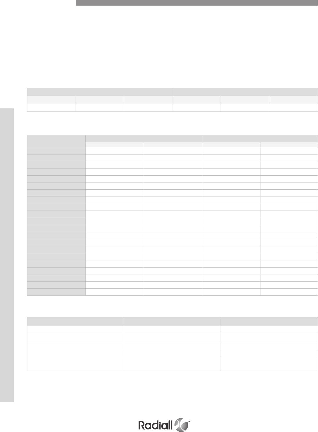
MASS G (OZ)
Shells
Includes screws, washers, insert retention plate and polarization hardware.
Plug Receptacle
Size 1 Size 2 Size 3 Size 1 Size 2 Size 3
110 (3.88) 130 (4.59) 220 (7.76) 130 (4.59) 140 (4.94) 245 (8.64)
INSERTS
Contact arrangement
designation
For plug shell For receptacle shell
Environmental type Non-environmental type Environmental type Non-environmental type
5C2 15.25 (0.54) 12.39 (0.44) 9.92 (0.35) 7,25 (0,26)
40 13.52 (0.48) 11.15 (0.39) 9.22 (0.33) 8,22 (0,29)
60 18.78 (0.66) 15.53 (0.55) 12.78 (0.45) 11,43 (0,40)
30T2 17.86 (0.63) 14.75 (0.52) 11.38 (0.40) 9,36 (0,33)
150 41.80 (1.47) 20.87 (0.74) 28.01 (0.99) 24,32 (0,86)
121 45.93 (1.62) 37.79 (1.33) 29.77 (1.05) 24,53 (0,87)
120T2 41.21 (1.45) 34.12 (1.20) 26.89 (0.95) 23,83 (0,84)
71C1/1C71 31.4 (1.11) 27.7 (0.98) 19.73 (0.70) 18,68 (0,66)
60 58.87 (2.08) 48.97 (1.73) 35.69 (1.26) 25,79 (0,91)
10T10 51.80 (1.83) 45.45 (1.60) 32.76 (1.16) 26,41 (0,93)
C4 /31.56 (1.11) /20,96 (0,74)
C2 /25.94 (0.91) /12,48 (0,44)
100 30.63 (1.08) 25.31 (0.89) 20.56 (0.73) 17,8 (0,63)
85 33.01 (1.16) 27.15 (0.96) 21.67 (0.76) 18,67 (0,66)
34 41.56 (1.47) 34.57 (1.22) 25.06 (0.88) 18,06 (0,64)
13C2 39.96 (1.41) 33.36 (1.18) 24.48 (0.86) 17,89 (0,63)
6T6 41.48 (1.46) 36.52 (1.29) 25.53 (0.90) 31,24 (1,10)
Q11 36.86 (1.30) 31.26 (1.10) 25.07 (0.88) 19,47 (0,69)
62Q2 31.85 (1.12) 26.24 (0.93) /13,2 (0,47)
68Q2 31.14 (1.10) 25.64 (0.90) 19.12 (0.67) 16,32 (0,58)
11Q2 37.39 (1.32) 30.88 (1.09) 24.38 (0.86) 17,87 (0,63)
CONTACTS
Contact size Pin Socket
22 0.12 (4 10-3) 0.15 (5.3 10-3)
20 0.22 (7.8 10-3)0.40 (14.1 10-3)
16 0.72 (25.4 10-3)0.75 (26.5 10-3)
12 1.50 (53.0 10-3)1.50 (53.0 10-3)
8619270: 5 (0.18)
619271: 6.5 (0.23)
COAX CONTACTS ELECTRICAL CHARACTERISTICS
- Nominal impedance: 50Ω.
- DWV: 1500 VAC – IR at 25 °C = 5000 MΩ.
- V.S.W.R.:
Size 5 1.3 from DC to 1500 MHz and insertion loss = 0.3 dB, Size 1 1.3 from DC to 5000 MHz
Characteristics
NSX SERIES
4-8
Our Most Important Connection is with You.™
Go online for data sheets & assembly instructions. Visit www.radiall.com and enter the part number.
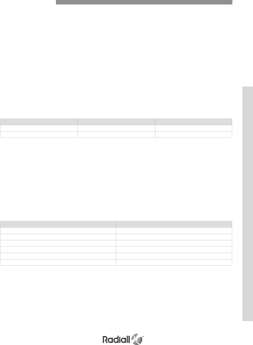
EMI/RFI acts directly on electronics systems whether by conduction
through the input or input cables or by induction (coupling).
Electronics equipment are particularly vulnerable to interferences and can be disturbed or damaged
by them. The serious consequences which may result, make it essential to protect such installations.
The first stage in protection is to install the equipment in a metal surrounding (FARADAY cage)
which protects it from some of the interferences; particularly those occurring by induction.
As to meet these requirements RADIALL offers plug connectors for
racks which are fitted with ground spring fingers.
Sizes 1, 2 and 3 plugs connectors fitted with ground spring fingers are available. These
connectors can be mated with ARINC 600 receptacle connectors. Their technical
characteristics are the same than those shown on page 4-8 except the following.
- Shell to shell conductivity:
(measured according to method 3007 of MIL-STD-1344A),
max warranty: 2,5 mΩ.
- Size 8 cavity grounding:
(measured according to method 3007 of MIL-STD-1344A),
max warranty: 10,0 mΩ.
- EMI shielding effectiveness:
(measured according to S280W552).
The minimum values warranty are as follows: Typical values
ELECTRICAL CHARACTERISTICS
Frequency (mhz) Leakage attenuation (db)
100 65
200 63
300 63
400 62
800 60
1000 60
MATERIALS
Description Material Plating
Shell Aluminum alloy Electroless nickel
Ground spring fingers Copper alloy Electroless nickel
EMI/RFI Performances
NSX SERIES
4-9
Our Most Important Connection is with You.™
Go online for data sheets & assembly instructions. Visit www.radiall.com and enter the part number.
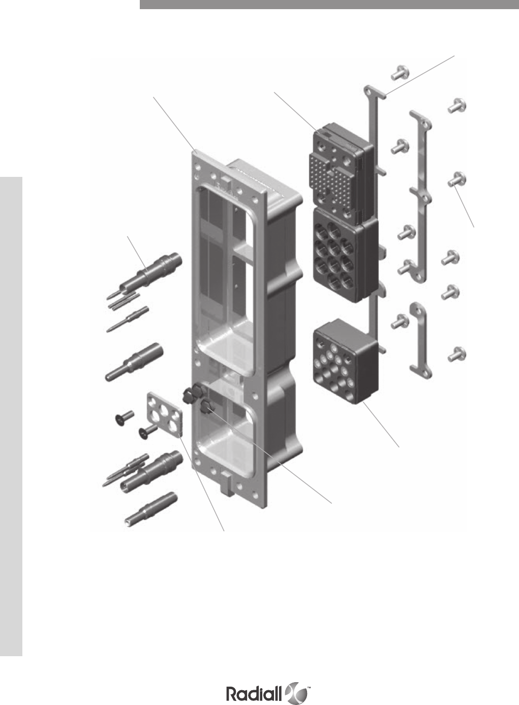
Detailed view of the various parts of the NSX connector series.
Insert for
cavities A & B
NSX Shell #2
Contacts
Polarization
retention plate
Polarization keys
Insert for cavity C
Screws
Inserts
retention
plates
Product Overview
NSX SERIES
4-10
Our Most Important Connection is with You.™
Go online for data sheets & assembly instructions. Visit www.radiall.com and enter the part number.

NSX N 3 P 301 X 00 01 -
NOTES:
(1) If you need to use reduced crimp barrel contacts, use code X and order signal and power contacts
separately. Coax, twinax or power size 5 or 8, coax size 1 must always be ordered separately
(2) Without polarization code, the connector is delivered with polarization hardware unassembled. Polarization
code 00, the connector is delivered without polarizing hardware. Polarization code from 01 to 216, the
connector is delivered with the polarization hardware assembled as defined by code
REMARK: dust caps conductive on receptacle and non conductive on plug are included in the delivery
NSX E/N/H/C – CONNECTORS FOR REAR REMOVABLE CONTACTS
How to Order
Series
Class
N: Non environmental
E: Environmental, with grommets and compound, plug with O-ring
H: Environmental, plug without O-ring (plug only)
C: Non environmental, with grommets
Shell size
1: Size 1
2: Size 2
3: Size 3
Shell style
S: RoHS plated receptacle
T: RoHS plated plug
R: Plated receptacle (alodine)
P: Plated plug (alodine)
F: Nickel plated receptacle
B: Nickel plated plug
M: Nickel plated plug EMI version (see pages 4-71)
Insert combination code
See combination code (pages 4-22 to 4-28) and contacts arrangements (pages 4-12 to 4-21)
T-cas application combination code : 310 (see page 4-25)
Contact termination (1)
X: Without contacts
S: Crimp contacts
Modification code
See pages 4-29 to 4-30
Polarization code (2)
See pages 4-31 to 4-33
Delivery code for T-CAS application
See page 4-42
NSX SERIES
4-11
Our Most Important Connection is with You.™
Go online for data sheets & assembly instructions. Visit www.radiall.com and enter the part number.
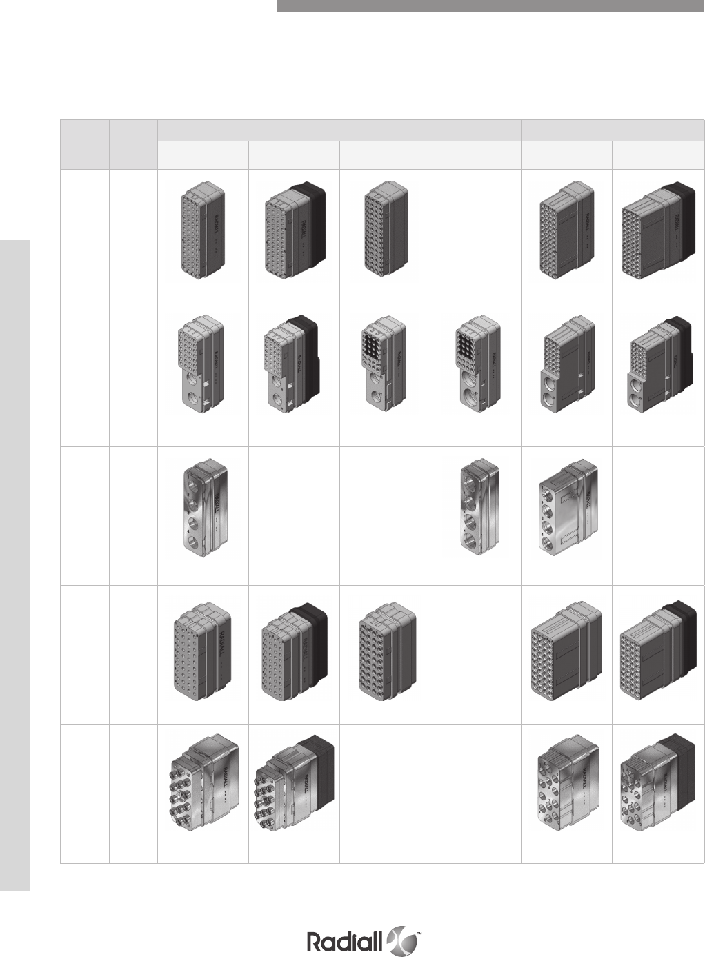
Insert
name
Shell size
cavity
Equipment side receptacle shell Avionic side plug shell
Version N Version E Version F Version G Version N Version E
60 1-A/B
60x#22 RR/RR 60x#22 RR/RR 60x#22 FR/FR
N/A
60x#22 RR/RR 60x#22 RR/RR
30T2 1-A/B
28x#22 RR/RR
2x#8G RR/RR
28x#22 RR/RR
2x#8G RR/RR
28x#22 FR/FR
2x#8G RR/RR
28x#22 FR/FR
2x#8G FR/FR
28x#22 RR/RR
2x#8G RR/RR
28x#22 RR/RR
2x#8G RR/RR
4C 1-A/B
4x#5G RR/RR
N/A N/A
4x#5G FR/FR 4x#5G RR/RR
N/A
40 1-C
40x#22 RR/RR 40x#22 RR/RR 40x#22 FR/FR
N/A
40x#22 RR/RR 40x#22 RR/RR
12F12 1-C
h12x#16 RR/RR
LuxCis®
12x#16 RR/RR
LuxCis®
N/A N/A
12x#16 RR/RR
LuxCis®
12x#16 RR/RR
LuxCis®
All insert names including letter Q can be equipped with quadrax contacts for each insert arrangement
the quantity and type of contacts is shown with insert view. RR/RR means contacts are rear
release and rear removable. FR/FR means contacts are front release and front removable. The
letter G means that the contact will be used in grounded cavity. LuxCis® contacts are always rear
release and rear removable. N/A means not available, please contact Radiall for further details.
NSX Shell Contact Arrangement
NSX SERIES
4-12
Our Most Important Connection is with You.™
Go online for data sheets & assembly instructions. Visit www.radiall.com and enter the part number.
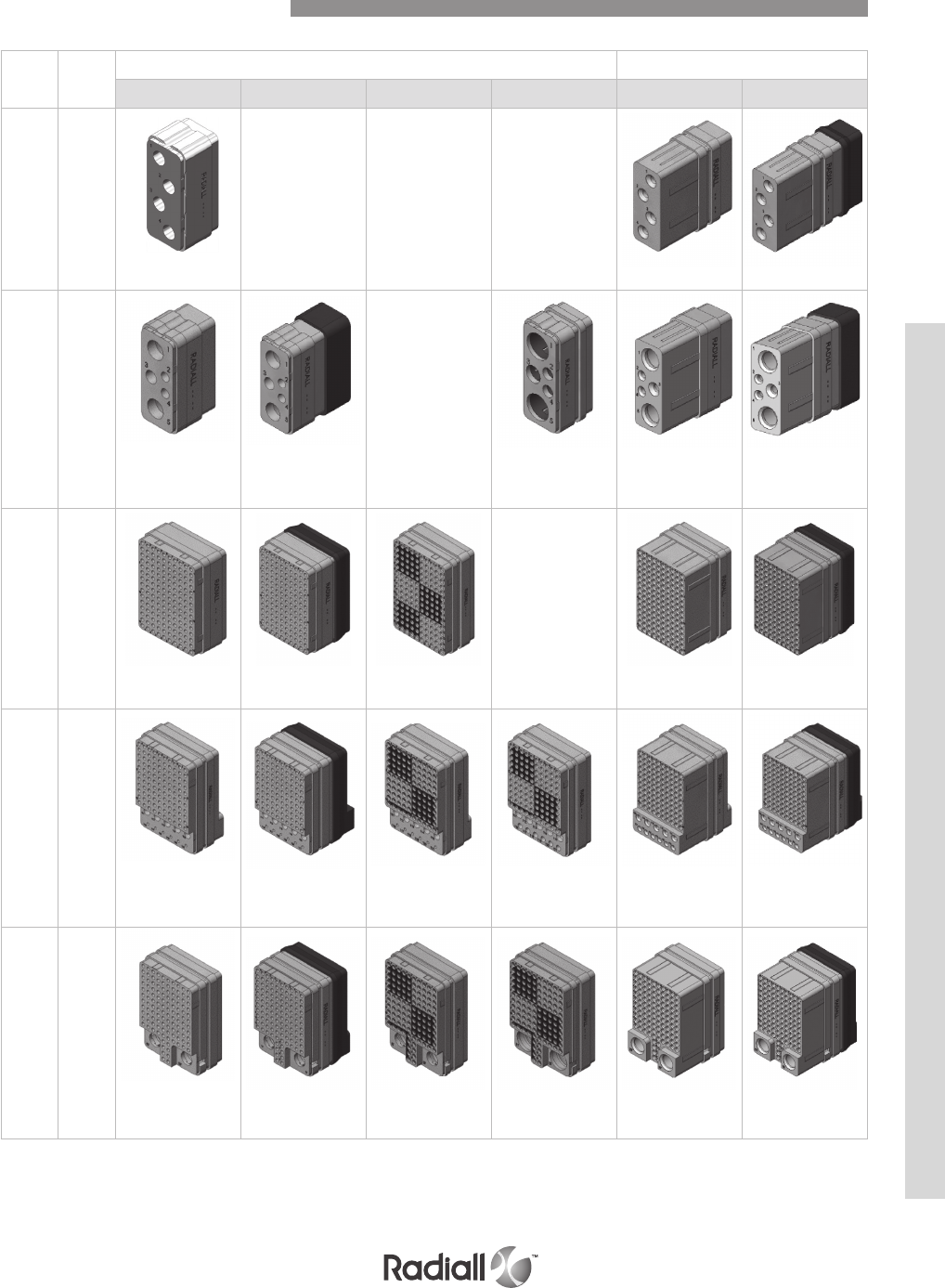
NOTE:
(1) For BPX serie, 4 insert will be supplied with FR/RR contacts.
NSX Shell Contact Arrangement
Insert
name
Shell
size
cavity
Equipment side receptacle shell Avionic side plug shell
Version N Version E Version F Version G Version N Version E
41-C
4x#12 RR/RR(1)
Available
(1)
N/A N/A
4x#12 RR/RR 4x#12 RR/RR
5C2 1-C N/A
2x#5 RR/RR
1x#12 RR/RR
2x#16 RR/RR
2x#5 RR/RR
1x#12 RR/RR
2x#16 RR/RR
2x#5 FR/FR
1x#12 FR/FR
2x#16 FR/FR
2x#5 RR/RR
1x#12 RR/RR
2x#16 RR/RR
2x#5 RR/RR
1x#12 RR/RR
2x#16 RR/RR
150 2/3-A/B N/A
150x#22 RR/RR 150x#22 RR/RR 150x#22 FR/FR 150x#22 RR/RR 150x#22 RR/RR
121 2/3-A/B
110x#22 RR/RR
6x#20 RR/RR
5x#16 RR/RR
110x#22 RR/RR
6x#20 RR/RR
5x#16 RR/RR
110x#22 FR/FR
6x#20 RR/RR
5x#16 RR/RR
110x#22 FR/FR
6x#20 FR/FR
5x#16 FR/FR
110x#22 RR/RR
6x#20 RR/RR
5x#16 RR/RR
110x#22 RR/RR
6x#20 RR/RR
5x#16 RR/RR
120T2 2/3-A/B
118x#22 RR/RR
2x#8G RR/RR
118x#22 RR/RR
2x#8G RR/RR
118x#22 FR/FR
2x#8G RR/RR
118x#22 FR/FR
2x#8G FR/FR
118x#22 RR/RR
2x#8G RR/RR
118x#22 RR/RR
2x#8G RR/RR
NSX SERIES
4-13
Our Most Important Connection is with You.™
Go online for data sheets & assembly instructions. Visit www.radiall.com and enter the part number.
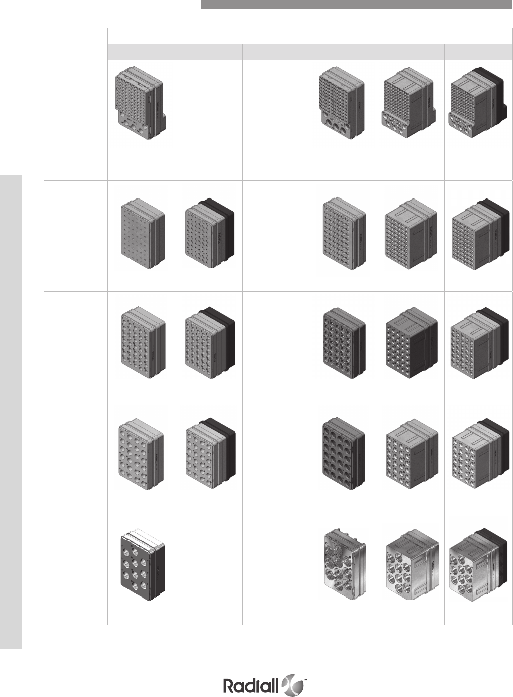
Insert
name
Shell
size
cavity
Equipment side receptacle shell Avionic side plug shell
Version N Version E Version F Version G Version N Version E
110 2/3-A/B N/A N/A
100x#22 RR/RR
5x#20 RR/RR
5x#12 RR/RR
100x#22 FR/FR
5x#20 FR/FR
5x#12 FR/FR
100x#22 RR/RR
5x#20 RR/RR
5x#12 RR/RR
100x#22 RR/RR
5x#20 RR/RR
5x#12 RR/RR
60A 2/3-A/B N/A
60x#20 RR/RR 60x#20 RR/RR 60x#20 FR/FR 60x#20 RR/RR 60x#20 RR/RR
35 2/3-A/B N/A
35x#16 RR/RR 35x#16 RR/RR 35x#16 FR/FR 35x#16 RR/RR 35x#16 RR/RR
24 2/3-A/B N/A
24x#12 RR/RR 24x#12 RR/RR 24x#12 FR/FR 24x#12 RR/RR 24x#12 RR/RR
10T10 2/3-A/B Available N/A
10x#8G RR/RR
(1)
(1) 10x#8G FR/FR 10x#8G RR/RR 10x#8G RR/RR
NOTE:
(1) For BPX serie, 10T10 insert will be supplied with FR/RR contacts.
NSX Shell Contact Arrangement
NSX SERIES
4-14
Our Most Important Connection is with You.™
Go online for data sheets & assembly instructions. Visit www.radiall.com and enter the part number.
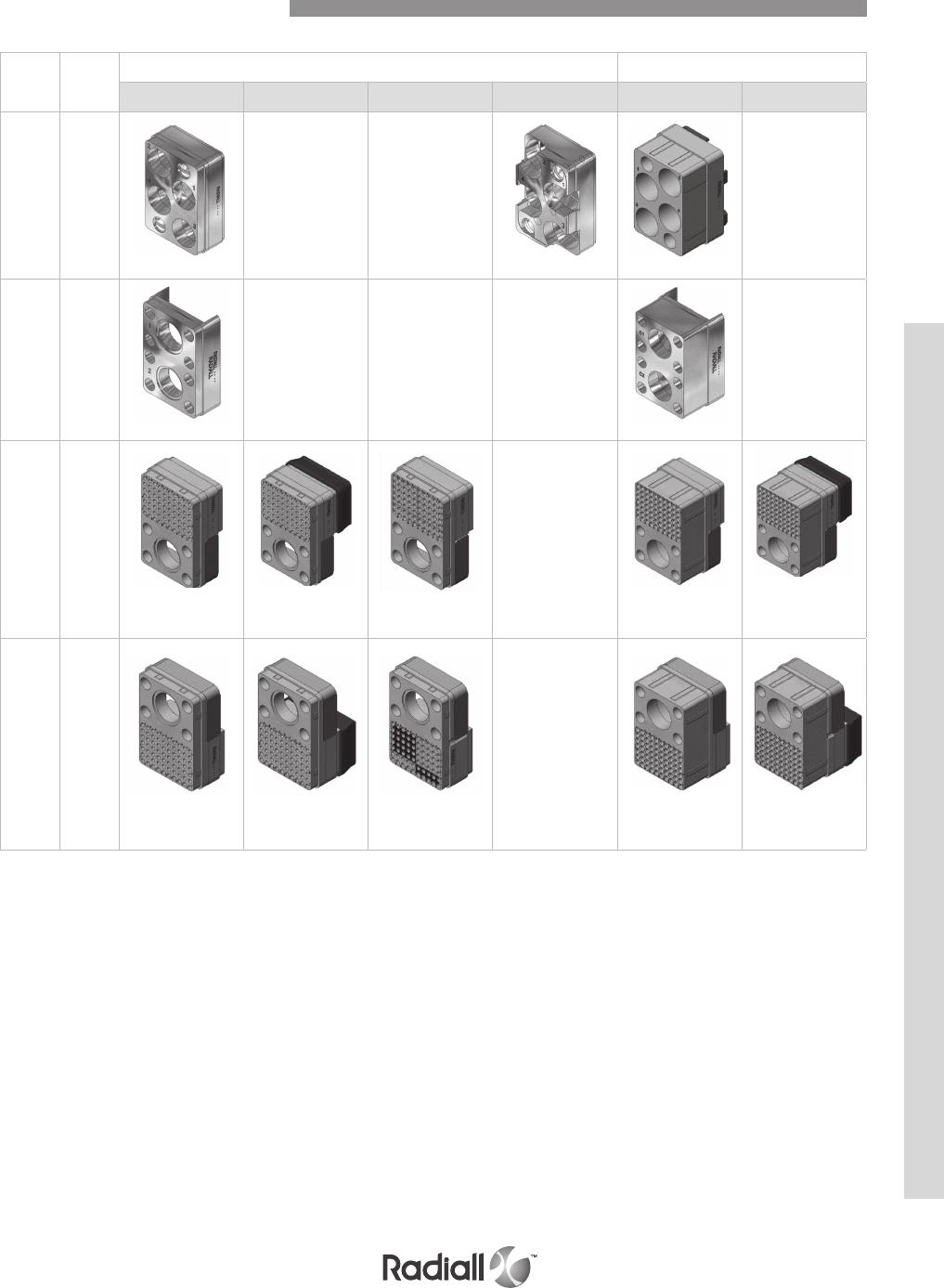
Insert
name
Shell
size
cavity
Equipment side receptacle shell Avionic side plug shell
Version N Version E Version F Version G Version N Version E
C4 2/3-A/B N/A N/A N/A
4x#1G FR/RR 4x#1G FR/FR 4x#1G FR/RR
C2 2/3-A/B N/A N/A N/A N/A
2x#1G FR/RR 2x#1G FR/RR
71C1 2/3-A/B N/A
70x#22 RR/RR
1x#1 FR/RR
70x#22 RR/RR
1x#1 FR/RR
70x#22 RR/RR
1x#1 FR/RR
70x#22 RR/RR
1x#1 FR/RR
70x#22 RR/RR
1x#1 FR/RR
1C71 2/3-A/B N/A
70x#22 RR/RR
1x#1 FR/RR
70x#22 RR/RR
1x#1 FR/RR
70x#22 FR/FR
1x#1 FR/RR
70x#22 RR/RR
1x#1 FR/RR
70x#22 RR/RR
1x#1 FR/RR
NSX Shell Contact Arrangement
NSX SERIES
4-15
Our Most Important Connection is with You.™
Go online for data sheets & assembly instructions. Visit www.radiall.com and enter the part number.
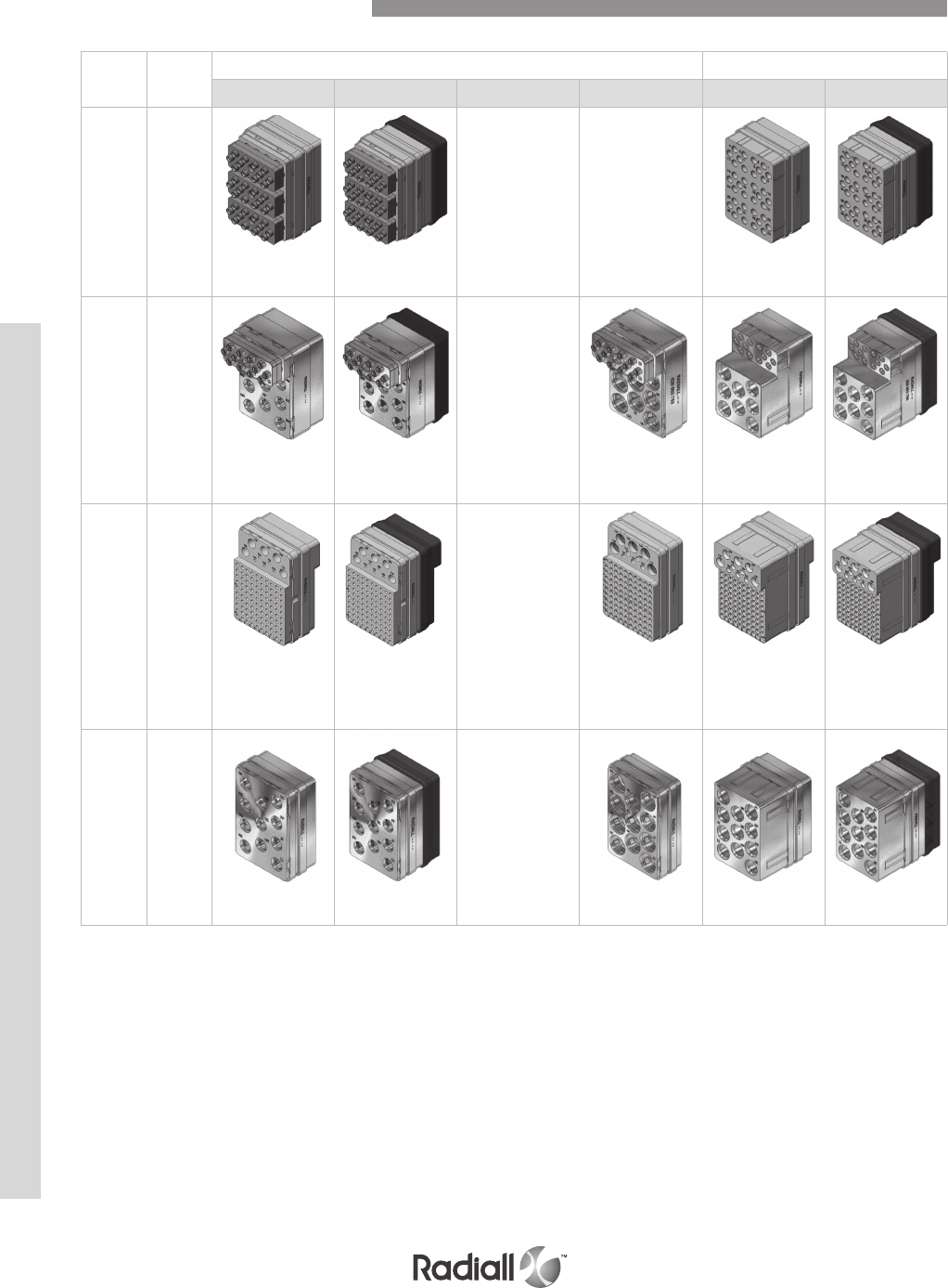
Insert
name
Shell size
cavity
Equipment side receptacle shell Avionic side plug shell
Version N Version E Version F Version G Version N Version E
36F36 2/3-A/B N/A N/A
36x#16 RR/RR
LuxCis®
36x#16 RR/RR
LuxCis®
36x#16 RR/RR
LuxCis®
36x#16 RR/RR
LuxCis®
20F12Q8 2/3-A/B N/A
12x#16 RR/RR
LuxCis®
8x#8G RR/RR
12x#16 RR/RR
LuxCis®
8x#8G RR/RR
12x#16 RR/RR
LuxCis®
8x#8G FR/FR
12x#16 RR/RR
LuxCis®
8x#8G RR/RR
12x#16 RR/RR
LuxCis®
8x#8G RR/RR
110R 2/3-A/B N/A
100x#22 RR/RR
5#20 RR/RR
5#12 RR/RR
100x#22 RR/RR
5#20 RR/RR
5#12 RR/RR
100x#22 FR/FR
5#20 FR/FR
5#12 FR/FR
100x#22 RR/RR
5#20 RR/RR
5#12 RR/RR
100x#22 RR/RR
5#20 RR/RR
5#12 RR/RR
Q11 2/3-A/B N/A
11x#8G RR/RR 11x#8G RR/RR 11x#8G FR/FR 11x#8G RR/RR 11x#8G RR/RR
NSX Shell Contact Arrangement
NSX SERIES
4-16
Our Most Important Connection is with You.™
Go online for data sheets & assembly instructions. Visit www.radiall.com and enter the part number.
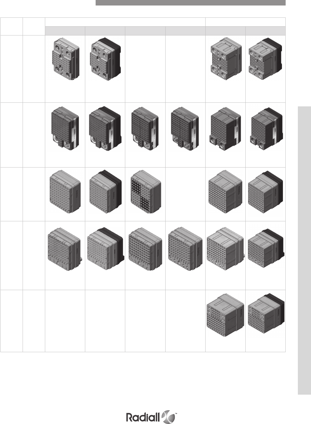
Insert
name
Shell size
cavity
Equipment side receptacle shell Avionic side plug shell
Version N Version E Version F Version G Version N Version E
68Q4 2/3-A/B N/A N/A
62x#22 RR/RR
6x#16 RR/RR
4x#8G RR/RR
62x#22 RR/RR
6x#16 RR/RR
4x#8G RR/RR
62x#22 RR/RR
6x#16 RR/RR
4x#8G RR/RR
62x#22 RR/RR
6x#16 RR/RR
4x#8G RR/RR
118Q2 2/3-A/B
118x#22 RR/RR
2x#8G RR/RR
118x#22 RR/RR
2x#8G RR/RR
118x#22 FR/FR
2x#8G RR/RR
118x#22 FR/FR
2x#8G FR/FR
118x#22 RR/RR
2x#8G RR/RR
118x#22 RR/RR
2x#8G RR/RR
100 2/3-C N/A
100x#22 RR/RR 100x#22 RR/RR 100x#22 FR/FR 100x#22 RR/RR 100x#22 RR/RR
85 2/3-C
80x#22 RR/RR
4x#20 RR/RR
1x#16 RR/RR
80x#22 RR/RR
4x#20 RR/RR
1x#16 RR/RR
80x#22 FR/FR
4x#20 RR/RR
1x#16 RR/RR
80x#22 FR/FR
4x#20 FR/FR
1x#16 FR/FR
80x#22 RR/RR
4x#20 RR/RR
1x#16 RR/RR
80x#22 RR/RR
4x#20 RR/RR
1x#16 RR/RR
84 2/3-C N/A N/A N/A N/A
80x#22 RR/RR
4x#20 RR/RR
80x#22 RR/RR
4x#20 RR/RR
NSX Shell Contact Arrangement
NSX SERIES
4-17
Our Most Important Connection is with You.™
Go online for data sheets & assembly instructions. Visit www.radiall.com and enter the part number.
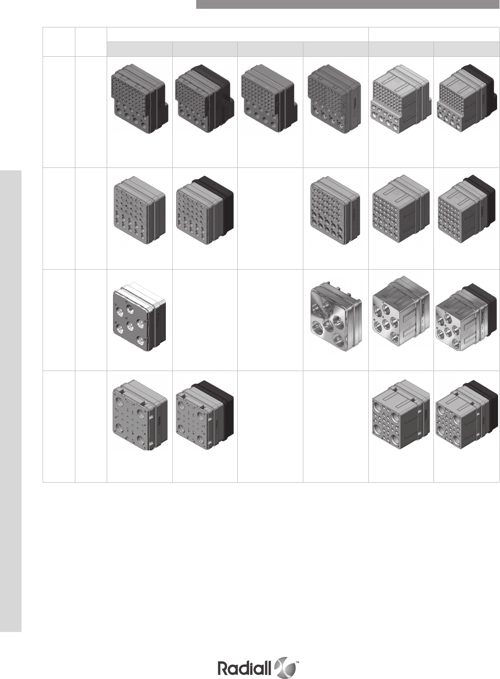
NOTE:
(1) For BPX serie, 6T6 insert will be supplied with FR/RR contacts
NSX Shell Contact Arrangement
Insert
name
Shell
size
cavity
Equipment side receptacle shell Avionic side plug shell
Version N Version E Version F Version G Version N Version E
59 2/3-C
50x#22 RR/RR
5x#16 RR/RR
4x#12 RR/RR
50x#22 RR/RR
5x#16 RR/RR
4x#12 RR/RR
50x#22 FR/FR
5x#16 RR/RR
4x#12 RR/RR
50x#22 FR/FR
5x#16 FR/FR
4x#12 FR/FR
50x#22 RR/RR
5x#16 RR/RR
4x#12 RR/RR
50x#22 RR/RR
5x#16 RR/RR
4x#12 RR/RR
34 2/3-C N/A
24x#20 RR/RR
10x#16 RR/RR
24x#20 RR/RR
10x#16 RR/RR
24x#20 FR/FR
10x#16 FR/FR
24x#20 RR/RR
10x#16 RR/RR
24x#20 RR/RR
10x#16 RR/RR
6T6 2/3-C Available N/A
6x#8G RR/RR(1) (1) 6x#8G FR/FR 6x#8G RR/RR 6x#8G RR/RR
24T4 2/3-C N/A N/A
20x#20 RR/RR
4x#8G RR/RR
20x#20 RR/RR
4x#8G RR/RR
20x#20 RR/RR
4x#8G RR/RR
20x#20 RR/RR
4x#8G RR/RR
NSX SERIES
4-18
Our Most Important Connection is with You.™
Go online for data sheets & assembly instructions. Visit www.radiall.com and enter the part number.

Insert
name
Shell size
cavity
Equipment side receptacle shell Avionic side plug shell
Version N Version E Version F Version G Version N Version E
Q6 2/3-C N/A
6x#8G RR/RR 6x#8G RR/RR 6x#8G FR/FR 6x#8G RR/RR 6x#8G RR/RR
20Q4 2/3-C N/A
20x#20 RR/RR
4x#8G RR/RR
20x#20 RR/RR
4x#8G RR/RR
20x#20 FR/FR
4x#8G FR/FR
20x#20 RR/RR
4x#8G RR/RR
20x#20 RR/RR
4x#8G RR/RR
68Q2 2/3-C N/A
68x#22 RR/RR
2x#8G RR/RR
68x#22 RR/RR
2x#8G RR/RR
68x#22 FR/FR
2x#8G FR/FR
68x#22 RR/RR
2x#8G RR/RR
68x#22 RR/RR
2x#8G RR/RR
62Q2 2/3-C N/A
60x#22 RR/RR
2x#16 RR/RR
2x#8G RR/RR
60x#22 RR/RR
2x#16 RR/RR
2x#8G RR/RR
60x#22 FR/FR
2x#16 FR/FR
2x#8G FR/FR
60x#22 RR/RR
2x#16 RR/RR
2x#8G RR/RR
60x#22 RR/RR
2x#16 RR/RR
2x#8G RR/RR
17F12Q2 2/3-C N/A
12x#16 RR/RR
LuxCis®
3x#16 RR/RR
2x#8G RR/RR
12x#16 RR/RR
LuxCis®
3x#16 RR/RR
2x#8G RR/RR
12x#16 RR/RR
LuxCis®
3x#16 FR/FR
2x#8G FR/FR
12x#16 RR/RR
LuxCis®
3x#16 RR/RR
2x#8G RR/RR
12x#16 RR/RR
LuxCis®
3x#16 RR/RR
2x#8G RR/RR
NSX Shell Contact Arrangement
NSX SERIES
4-19
Our Most Important Connection is with You.™
Go online for data sheets & assembly instructions. Visit www.radiall.com and enter the part number.
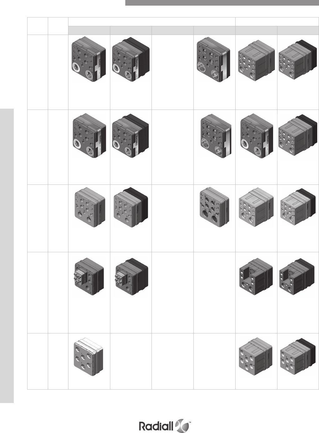
Insert
name
Shell
size
cavity
Equipment side receptacle shell Avionic side plug shell
Version N Version E Version F Version G Version N Version E
11Q2 2/3-C N/A
4x#20 RR/RR
3x#16 RR/RR
4x#12 RR/RR
2x#8G RR/RR
4x#20 RR/RR
3x#16 RR/RR
4x#12 RR/RR
2x#8G RR/RR
4x#20 FR/FR
3x#16 FR/FR
4x#12 FR/FR
2x#8G FR/FR
4x#20 RR/RR
3x#16 RR/RR
4x#12 RR/RR
2x#8G RR/RR
4x#20 RR/RR
3x#16 RR/RR
4x#12 RR/RR
2x#8G RR/RR
11WQ2 2/3-C N/A
4x#20 RR/RR
3x#16 RR/RR
4x#12 RR/RR
2x#8G RR/RR
4x#20 RR/RR
3x#16 RR/RR
4x#12 RR/RR
2x#8G RR/RR
4x#20 FR/FR
3x#16 FR/FR
4x#12 FR/FR
2x#8G FR/FR
4x#20 RR/RR
3x#16 RR/RR
4x#12 RR/RR
2x#8G RR/RR
4x#20 RR/RR
3x#16 RR/RR
4x#12 RR/RR
2x#8G RR/RR
13C2 2/3-C N/A
4x#20 RR/RR
3x#16 RR/RR
4x#12 RR/RR
2x#5 RR/RR
4x#20 RR/RR
3x#16 RR/RR
4x#12 RR/RR
2x#5 RR/RR
4x#20 FR/FR
3x#16 FR/FR
4x#12 FR/FR
2x#5 FR/FR
4x#20 RR/RR
3x#16 RR/RR
4x#12 RR/RR
2x#5 RR/RR
4x#20 RR/RR
3x#16 RR/RR
4x#12 RR/RR
2x#5 RR/RR
12F5C2 2/3-C N/A N/A
1x#16 RR/RR
5x#16 RR/RR
LuxCis®
4x#12 RR/RR
2x#5 RR/RR
1x#16 RR/RR
5x#16 RR/RR
LuxCis®
4x#12 RR/RR
2x#5 RR/RR
1x#16 RR/RR
5x#16 RR/RR
LuxCis®
4x#12 RR/RR
2x#5 RR/RR
1x#16 RR/RR
5x#16 RR/RR
LuxCis®
4x#12 RR/RR
2x#5 RR/RR
6P6 2/3-C Available N/A N/A
6x#8 RR/RR(1) (1) 6x#8 RR/RR 6x#8 RR/RR
NOTE:
(1) For BPX series, 6P6 insert will be supplied with FR/RR contacts
NSX Shell Contact Arrangement
NSX SERIES
4-20
Our Most Important Connection is with You.™
Go online for data sheets & assembly instructions. Visit www.radiall.com and enter the part number.
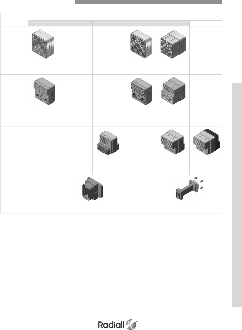
Insert
name
Shell
size
cavity
Equipment side receptacle shell Avionic side plug shell
Version N Version E Version F Version G Version N Version E
15T6Q2 2/3-C
7x#16 RR/RR
6x#10 RR/RR
2x#8G RR/RR
N/A N/A
7x#16 FR/FR
6x#10 FR/FR
2x#8G FR/FR
7x#16 RR/RR
6x#10 RR/RR
2x#8G RR/RR
N/A
46Q2 2/3-C
40x#22 RR/RR
2x#16 RR/RR
4x#12 RR/RR
2x#8G RR/RR
N/A N/A
40x#22 RR/RR
2x#16 RR/RR
4x#12 RR/RR
2x#8G RR/RR
N/A
40x#22 FR/FR
2x#16 FR/FR
4x#12 FR/FR
2x#8G FR/FR
62F12 2/3-C N/A N/A
50x#22 FR/FR
12x#16 RR/RR
LuxCis®
N/A
50x#22 RR/RR
12x#16 RR/RR
LuxCis®
50x#22 RR/RR
12x#16 RR/RR
LuxCis®
WAVE
GUIDE 2 - A&B
Wave guide
equipment side Wave guide
avionic side
NSX Shell Contact Arrangement
NSX SERIES
4-21
Our Most Important Connection is with You.™
Go online for data sheets & assembly instructions. Visit www.radiall.com and enter the part number.
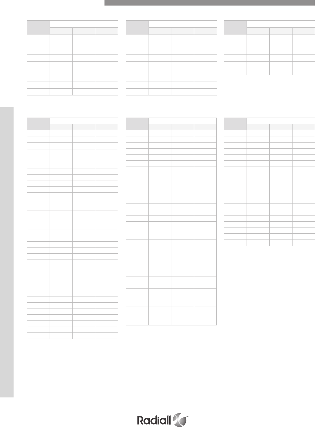
Code Insert combination on shell
Cavity A Cavity B Cavity C
101 60 60 5C2
102 60 60 BLANK
103 BLANK 60 5C2
104 60 BLANK 5C2
105 BLANK BLANK 5C2
106 60 BLANK BLANK
107 30T2 30T2 40
108 60 60 40
109 BLANK 60 BLANK
Code Insert combination on shell
Cavity A Cavity B Cavity C
201 150 150 13C2
202 71C1 150 13C2
203 71C1 71C1 13C2
204 wave
guide 150 13C2
205 150 71C1 13C2
206 150 150 100
207 71C1 150 100
208 150 71C1 100
209 71C1 71C1 100
210 wave
guide 71C1 100
211 150 150 BLANK
212 71C1 71C1 BLANK
213 71C1 wave
guide 13C2
214 wave
guide 71C1 13C2
215 150 73C3 13C2
216 C2 1C71 85
217 150 C5 13C2
218 150 wave
guide 13C2
219 150 2C 13C2
220 71C1 C2 85
221 1C71 71C1 13C2
222 BLANK 150 13C2
223 BLANK BLANK 13C2
224 150 BLANK 13C2
225 150 71C1 BLANK
226 150 150 85
227 150 150 34
228 C4 150 13C2
229 120T2 120T2 100
Code Insert combination on shell
Cavity A Cavity B Cavity C
230 121 121 6T6
233 120T2 150 100
234 60A 60A 13C2
235 150 C4 34
236 C4 C4 34
237 150 120T2 100
243 150 BLANK 100
244 150 BLANK BLANK
245 71C1 71C1 85
246 71C1 BLANK BLANK
247 BLANK 150 85
248 BLANK 150 100
249 BLANK 150 BLANK
250 BLANK 71C1 BLANK
251 BLANK BLANK 100
252 BLANK wave
guide 100
253 C2 150 13C2
254 C2 1C71 100
255 C2 1C71 13C2
256 C2 71C1 13C2
257 C2 C2 13C2
258 ---
259 C4 C4 85
260 wave
guide 150 85
261 wave
guide 150 100
262 150 60A 34
264 BLANK 24 100
265 24 150 13C2
266 121 121 85
Code Insert combination on shell
Cavity A Cavity B Cavity C
268 60A 121 59
270 150 150 59
271 C4 120T2 13C2
272 150 150 24T4
273 150 C2 13C2
274 C2 71C1 85
275 121 60A 34
276 121 BLANK 100
277 1C71 150 13C2
278 71C1 1C71 13C2
279 150 121 13C2
280 120T2 121 34
281 150 121 34
282 C4 BLANK 13C2
283 150 60A 13C2
284 120T2 120T2 13C2
285 24 60A 100
286 60A 60A 34
287 BLANK 60A 100
Code Insert combination on shell
Cavity A Cavity B Cavity C
120 60 30T2 40
121 4C 4C 40
122 30T2 60 5C2
123 60 60 12F12
124 4C BLANK 12F12
125 BLANK BLANK 12F12
Code Insert combination on shell
Cavity A Cavity B Cavity C
111 BLANK 30T2 40
112 60 4C 5C2
113 60 4C 40
114 60 BLANK 40
115 BLANK BLANK BLANK
116 4C 60 40
117 BLANK BLANK 40
118 60 30T2 5C2
119 30T2 BLANK 5C2
FOR SHELL SIZE 1
FOR SHELL SIZE 2
Insert Combination Code
NSX SERIES
4-22
Our Most Important Connection is with You.™
Go online for data sheets & assembly instructions. Visit www.radiall.com and enter the part number.

FOR SHELL SIZE 2
Code Insert combination on shell
Cavity A Cavity B Cavity C
288 BLANK 121 BLANK
289 BLANK BLANK 85
290 150 121 100
291 121 150 100
292 121 121 BLANK
294 121 121 13C2
295 Q11 Q11 85
297 120T2 60A BLANK
298 121 60A BLANK
299 BLANK BLANK 59
501 24 60A 59
502 121 Q11 Q6
503 150 BLANK 11Q2
504 150 BLANK 34
505 Q11 BLANK 34
506 150 150 11Q2
507 150 150 68Q2
508 24 24 100
509 150 Q11 13C2
510 121 121 100
511 24 150 100
512 Q11 Q11 62Q2
513 Q11 Q11 34
514 BLANK 60A 34
515 BLANK BLANK BLANK
516 121 121 34
517 BLANK 120T2 13C2
518 Q11 BLANK 62Q2
519 Q11 Q11 68Q2
520 150 121 24T4
521 Q11 150 62Q2
522 20F12T8 120T2 13C2
524 120T2 120T2 11Q2
527 120T2 120T2 85
528 150 150 11WQ2
529 35 35 62Q2
530 24 BLANK 85
532 20F12T8 121 34
533 120T2 C4 24T4
534 BLANK Q11 85
535 150 35 24T4
536 BLANK 150 24T4
537 118Q2 118Q2 24T4
538 150 120T2 13C2
539 Q11 Q11 BLANK
540 120T2 C4 13C2
541 1C71 Q11 13C2
542 121 C4 Q6
543 120T2 Q11 13C2
544 120T2 120T2 24T4
545 C4 Q11 85
546 121 60A 100
547 BLANK 150 20Q4
548 150 35 20Q4
551 121 118Q2 24T4
552 150 Q11 11Q2
554 BLANK 118Q2 13C2
555 BLANK 71C1 13C2
556 BLANK BLANK 62Q2
557 BLANK Q11 62Q2
558 BLANK Q11 BLANK
559 150 150 20Q4
560 150 Q11 85
561 150 120T2 85
562 121 BLANK BLANK
563 24 24 34
564 BLANK BLANK 34
565 150 24 34
566 150 121 BLANK
567 150 118Q2 BLANK
Code
Insert combination on shell
Cavity A Cavity B Cavity C
Code
Insert combination on shell
Cavity A Cavity B Cavity C
569 118Q2 118Q2 BLANK
570 Q11 150 11Q2
571 150 118Q2 13C2
572 150 C4 13C2
573 150 24 13C2
574 150 121 59
575 60A 150 34
576 150 150 Q6
577 1C71 118Q2 12F5C2
578 150 121 20Q4
579 C4 118Q2 85
580 150 BLANK 59
581 118Q2 118Q2 20Q4
582 BLANK 71C1 11Q2
584 121 121 59
585 20F12Q8 BLANK 11Q2
586 150 Q11 34
587 150 118Q2 85
588 Q11 Q11 11Q2
590 BLANK Q11 Q6
591 20F12T8 150 100
592 BLANK BLANK 11Q2
593 20F12Q8 121 BLANK
594 C118Q2 85
596 BLANK 118Q2 11WQ2
597 150 121 Q6
598 20F12Q8 118Q2 13C2
599 C4 24 100
801 C4 Q11 59
802 BLANK 120T2 24T4
803 Q11 20F12Q8 11Q2
804 Q11 20F12Q8 17F12Q2
806 C4 60A 59
807 Q11 150 85
809 C4 C4 59
Insert Combination Code
NSX SERIES
4-23
Our Most Important Connection is with You.™
Go online for data sheets & assembly instructions. Visit www.radiall.com and enter the part number.
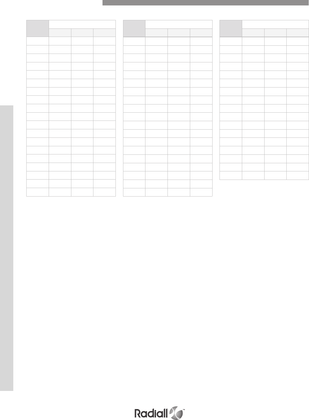
FOR SHELL SIZE 2
Code
Insert combination on shell
Cavity A Cavity B Cavity C
810 Q11 Q11 13C2
811 150 150 12F5C2
812 60A C2 13C2
813 BLANK Q11 13C2
814 120T2 150 13C2
815 60A 35 24T4
817 20F12Q8 Q11 62Q2
818 60A C2 24T4
819 60A 24 34
820 Q11 121 BLANK
822 Q11 35 100
823 20F12T8 118Q2 13C2
824 20F12Q8 BLANK BLANK
825 20F12T8 BLANK BLANK
826 150 20F12Q8 34
827 Q11 150 59
828 150 BLANK 85
829 120T2 BLANK 85
830 118Q2 120T2 BLANK
831 120T2 120T2 BLANK
832 Q11 121 100
833 150 150 17F12Q2
834 110R 150 17F12Q2
835 121 121 11Q2
838 Q11 BLANK 68Q2
839 60A BLANK 34
840 150 110 11Q2
841 150 110 34
842 71C1 118Q2 12F5C2
843 110 110 BLANK
844 150 121 62F12
845 150 20F12Q8 13C2
846 C4 150 62F12
847 C4 150 11Q2
848 24 150 6Q6
849 150 150 10
850 150 110 13C2
851 36F36 150 85
Code
Insert combination on shell
Cavity A Cavity B Cavity C
852 150 121 11Q2
853 118Q2 150 11Q2
854 20F12Q8 118Q2 59
855 20F12Q8 Q11 100
856 BLANK 110 13C2
857 BLANK 36F36 BLANK
858 118Q2 118Q2 11Q2
859 150 36F36 13C2
860 150 118Q2 11Q2
861 118Q2 118Q2 59
862 150 118Q2 62Q2
863 Q11 Q11 17F12Q2
864 150 Q11 46Q2
865 118Q2 150 13C2
866 121 110 13C2
867 C4 C2 BLANK
868 150 118Q2 24T4
Code
Insert combination on shell
Cavity A Cavity B Cavity C
Insert Combination Code
NSX SERIES
4-24
Our Most Important Connection is with You.™
Go online for data sheets & assembly instructions. Visit www.radiall.com and enter the part number.

FOR SHELL SIZE 3
Code
Insert combination on shell
Cavity A Cavity B Cavity C Cavity D Cavity E Cavity F
301 150 150 13C2 150 150 13C2
302 150 150 100 150 150 13C2
303 150 150 13C2 150 150 100
304 150 150 100 150 150 100
305 150 150 BLANK 150 150 BLANK
306 150 71C1 13C2 150 71C1 13C2
307 71C1 71C1 13C2 71C1 71C1 13C2
308 C2 C2 13C2 C2 150 100
309 150 150 13C2 150 71C1 100
310 C4 C4 13C2 BLANK 150 100
311 150 150 85 150 150 85
312 BLANK BLANK 13C2 BLANK BLANK 13C2
313 BLANK BLANK 13C2 BLANK BLANK 100
314 BLANK BLANK 13C2 BLANK 150 100
315 150 150 13C2 150 150 BLANK
316 24 BLANK 13C2 150 150 BLANK
317 120T2 150 34 120T2 150 34
320 150 60A 100 150 60A 100
321 150 150 100 150 BLANK BLANK
322 150 150 100 150 150 34
323 150 150 100 71C1 71C1 100
324 150 150 100 C2 BLANK BLANK
325 150 150 13C2 C2 C2 13C2
326 150 71C1 100 150 150 100
327 150 71C1 100 150 150 13C2
328 C2 C2 13C2 150 150 13C2
329 C2 C2 13C2 C4 150 100
330 C4 C4 13C2 BLANK BLANK BLANK
331 71C1 150 100 150 150 100
332 C4 C4 13C2 C4 C4 85
333 71C1 71C1 100 71C1 71C1 100
334 71C1 71C1 BLANK 71C1 71C1 BLANK
335 71C1 C4 100 71C1 C4 100
336 BLANK 150 13C2 BLANK 150 13C2
337 BLANK BLANK 100 BLANK BLANK 13C2
338 C2 150 100 150 150 100
339 C2 C2 100 C2 C2 100
340 C2 C2 13C2 C2 C2 13C2
341 C4 C4 100 C4 C4 100
342 C4 C4 13C2 C4 C4 13C2
NSX T CAS connectors (insert code combination 310) are installed on equipment for use on T CAS (Traffic Collision Avoidance Systems)
C4 insert uses size 1 RF coaxial contacts (see pages 4-42 to 4-43)
Insert Combination Code
NSX SERIES
4-25
Our Most Important Connection is with You.™
Go online for data sheets & assembly instructions. Visit www.radiall.com and enter the part number.

FOR SHELL SIZE 3
Code
Insert combination on shell
Cavity A Cavity B Cavity C Cavity D Cavity E Cavity F
343 BLANK 150 100 150 150 13C2
344 24 150 13C2 24 150 13C2
345 60A 24 BLANK 60A 24 BLANK
346 150 24 100 150 150 34
348 C4 120T2 100 150 150 13C2
350 150 120T2 100 150 120T2 59
351 150 150 34 150 150 34
352 24 24 100 24 24 34
353 150 150 59 150 150 59
354 150 150 34 150 24 100
355 C4 150 13C2 BLANK 150 13C2
356 150 150 100 60A 60A 100
357 C4 C4 13C2 150 150 100
358 C4 C4 13C2 121 150 100
359 121 121 13C2 121 121 13C2
360 150 150 6T6 24 24 13C2
361 150 BLANK 13C2 150 150 BLANK
362 24 24 34 150 121 34
363 150 150 59 24 60A 59
364 60A 24 59 150 150 59
365 24 60A 100 24 60A 100
366 150 150 84 150 150 100
367 150 150 59 120T2 120T2 100
368 150 150 59 150 150 34
369 150 150 59 150 150 100
370 60A 60A 100 60A 60A 100
371 C4 C4 13C2 C2 150 100
372 150 150 BLANK 121 BLANK 13C2
373 150 150 13C2 120T2 120T2 100
374 150 150 68Q2 150 150 68Q2
375 150 150 100 150 150 68Q2
376 150 150 68Q2 150 150 BLANK
377 120T2 150 13C2 120T2 150 100
378 Q11 150 13C2 150 150 13C2
379 60A 150 34 150 150 34
380 C4 120T2 11Q2 C4 120T2 13C2
381 C4 120T2 11Q2 C4 120T2 11Q2
382 150 150 11Q2 150 150 11Q2
383 150 150 BLANK Q11 150 85
384 Q11 150 85 150 150 BLANK
Insert Combination Code
NSX SERIES
4-26
Our Most Important Connection is with You.™
Go online for data sheets & assembly instructions. Visit www.radiall.com and enter the part number.

FOR SHELL SIZE 3
Code Insert combination on shell
Cavity A Cavity B Cavity C Cavity D Cavity E Cavity F
387 Q11 Q11 62Q2 Q11 Q11 62Q2
388 Q11 Q11 Q6 Q11 Q11 62Q2
389 Q11 150 11Q2 150 150 68Q2
390 150 150 11Q2 BLANK BLANK BLANK
393 BLANK BLANK 13C2 150 BLANK BLANK
394 BLANK BLANK 13C2 150 BLANK 13C2
395 Q11 Q11 100 Q11 Q11 100
396 BLANK BLANK BLANK BLANK BLANK BLANK
397 Q11 Q11 11Q2 Q11 150 11Q2
398 150 120T2 85 150 120T2 85
399 121 BLANK 6T6 60A BLANK 13C2
601 60A 60A 13C2 60A 60A 13C2
602 Q11 150 11Q2 150 150 11Q2
603 24 BLANK 13C2 BLANK BLANK 13C2
604 150 150 BLANK 150 150 100
605 150 Q11 11Q2 150 Q11 68Q2
607 24 24 13C2 24 24 100
608 24 24 13C2 24 24 68Q2
609 150 150 34 150 120T2 13C2
610 150 150 34 150 Q11 13C2
611 BLANK 150 13C2 BLANK 150 100
613 Q11 150 68Q2 150 150 13C2
614 150 150 100 BLANK BLANK BLANK
615 150 150 100 150 150 59
616 150 150 13C2 60A 120T2 34
617 60A 120T2 13C2 60A 120T2 13C2
618 150 150 Q6 150 150 Q6
619 Q11 Q11 11Q2 150 150 100
620 24 24 34 24 BLANK 34
621 150 150 34 150 60A 34
622 120T2 150 100 120T2 150 100
623 C4 C4 34 C4 C4 BLANK
624 150 150 13C2 60A 60A 34
626 C4 C4 13C2 120T2 150 100
627 C4 120T2 BLANK C4 120T2 11Q2
Insert Combination Code
NSX SERIES
4-27
Our Most Important Connection is with You.™
Go online for data sheets & assembly instructions. Visit www.radiall.com and enter the part number.

FOR SHELL SIZE 3
Code Insert combination on shell
Cavity A Cavity B Cavity C Cavity D Cavity E Cavity F
629 C4 120T2 17F12Q2 C4 120T2 11Q2
630 C4 C4 BLANK C4 C4 34
631 BLANK 150 13C2 BLANK Q11 BLANK
632 BLANK 150 13C2 150 150 68Q2
633 150 150 100 Q11 Q11 11Q2
634 150 120T2 34 150 120T2 34
635 Q11 121 11Q2 Q11 121 11Q2
636 150 150 11Q2 150 150 100
637 BLANK 150 11Q2 150 150 68Q2
638 Q11 150 62Q2 Q11 150 62Q2
639 Q11 121 13C2 Q11 121 13C2
641 150 150 BLANK 150 150 13C2
642 121 60A 59 121 60A 13C2
643 Q11 Q11 Q6 Q11 Q11 Q6
644 150 Q11 34 Q11 Q11 34
645 150 150 11Q2 150 150 BLANK
646 150 BLANK 13C2 150 BLANK BLANK
647 C4 120T2 17F12Q2 C4 120T2 13C2
648 BLANK BLANK 17F12Q2 BLANK BLANK BLANK
649 150 150 15T6Q2 150 150 15T6Q2
651 Q11 118Q2 59 Q11 118Q2 59
652 121 121 34 121 121 34
653 C4 C4 13C2 C4 150 100
654 C4 150 62F12 C4 150 11Q2
655 36F36 150 11Q2 150 150 68Q2
656 71C1 71C1 85 71C1 71C1 85
657 Q11 Q11 34 120T2 150 13C2
660 C4 BLANK BLANK 150 BLANK 13C2
661 Q11 Q11 85 Q11 Q11 85
662 BLANK BLANK 13C2 150 150 100
664 Q11 Q11 100 118Q2 Q11 34
Insert Combination Code
NSX SERIES
4-28
Our Most Important Connection is with You.™
Go online for data sheets & assembly instructions. Visit www.radiall.com and enter the part number.

Code Receptacle shell Plug shell
00
Ø 3.76
Ø (.148)
All holes
Ø 3.76
Ø (.148)
All holes
01
Shell size 1: Qty = 4
6-32 UNC &
Qty = 6 4-40 UNC
Shell size 2: Qty = 6
6-32 UNC
Shell size 3: Qty = 10
6-32 UNC
6-32 UNC
Shell size 1: Qty = 4
Shell size 2: Qty = 4
Shell size 3: Qty = 8
Size 1 plug is without
threaded inserts
03
Shell size 1: Qty = 6
4-40 UNC 2B &
Qty = 3 holes Ø 3.05 (.120)
Shell size 2: Qty = 6 &
Qty = 4 holes Ø3.76 (.148)
Shell size 3: Qty = 10 & Qty = 4
holes Ø3.76 (.148)
Shell size 1 plug is without
threaded inserts
Shell size 1: Qty = 4
4-40 UNC
Shell size 2: Qty= 4 4-40 UNC
& Qty= 6 holes Ø3.76 (.148)
Shell size 3: Qty = 8 &
Qty= 6 holes Ø3.76 (.148)
08
4-40 UNC
All holes
Shell sizes 2 and 3 only
4-40 UNC
All holes
Shell sizes 2 and 3 only
09
6-32 UNC
All holes
Shell sizes 2 and 3 only
6-32 UNC
All holes
Shell sizes 2 and 3 only
10
M3 x 0.50
All holes
Shell size 1 receptacle is
without threaded inserts
M3 x 0.50
All holes
Shell size 1 plug is without
threaded inserts
Modification Code
NSX SERIES
4-29
Our Most Important Connection is with You.™
Go online for data sheets & assembly instructions. Visit www.radiall.com and enter the part number.
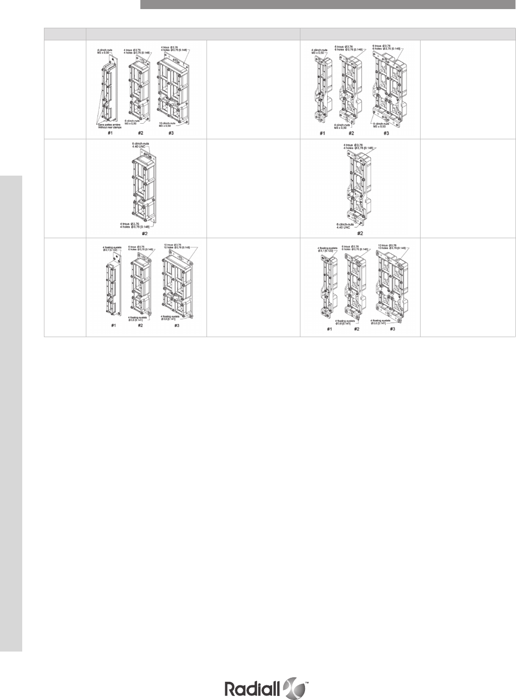
Code Receptacle shell Plug shell
11
M3 x 0.50
Shell size 1: Qty = 4
Shell size 2: Qty = 6
Shell size 3: Qty = 10
Size 1 receptacle is without
threaded inserts
M3 x 0.50
Shell size 1: Qty = 4
Shell size 2: Qty = 4
Shell size 3: Qty = 8
Shell size 1 plug is without
threaded inserts
12
4-40 UNC
6 holes (4 close to the bosses
and 2 at the polarization
system level)
Available for shell size 2 only
4-40 UNC
6 holes (4 in to the corner and
2 at the polarization system
level)
Available for shell size 2 only
23
Shell size 1: Qty = 4 floating
eyelets Ø 3.1 (.122)
Shell size 2: Qty = 6 Ø 3.76
(.148) + 4 floating eyelets
Shell size 3: Qty = 10 Ø 3.76
(.148) + 4 floating eyelets
Shell size 1: Ø 3.1
Ø (.122)
Shell size 2 and 3: Ø 3.6
Ø (.141)
4 floating eyelets
Modification Code
NSX SERIES
4-30
Our Most Important Connection is with You.™
Go online for data sheets & assembly instructions. Visit www.radiall.com and enter the part number.

POSITION OF POLARIZATION KEYS AND POSTS
POSITION CODING
Dark area represents the polarizing post
Clear portion represents the key hole
POSTS KEYS
Polarization Code
Connectors are shown front side, with “RADIALL” upward
NSX SERIES
4-31
Our Most Important Connection is with You.™
Go online for data sheets & assembly instructions. Visit www.radiall.com and enter the part number.

Code
number
Receptacle shell Plug shell
Le
key
Center
key
Right
key
Le
post
Center
post
Right
post
00------
01444111
02443211
03442311
04441411
05446511
06445611
07544116
08543216
09542316
10541416
11546516
12545616
13644115
14643215
15642315
16641415
17646615
18645515
19144114
20143214
21142314
22141414
23146514
24145614
25244113
26243213
27242313
28241413
29246513
30245613
31344112
32343212
33342312
34341412
35346612
36345512
37434121
38433221
39432321
40431421
41436521
42435621
43534126
44533226
45532326
46531426
47536526
48535626
49634125
Code
number
Receptacle shell Plug shell
Le
key
Center
key
Right
key
Le
post
Center
post
Right
post
50 633225
51 6 3 2 3 2 5
52 631425
53 6 3 6 5 2 5
54 6 3 5 6 2 5
55 1 3 4 1 2 4
56 1 3 3 2 2 4
57 1 3 2 3 2 4
58 1 3 1 4 2 4
59 1 3 6 5 2 4
60 1 3 5 6 2 4
61 2 3 4 1 2 3
62 2 3 3 2 2 3
63 2 3 2 3 2 3
64 2 3 1 4 2 3
65 2 3 6 5 2 3
66 2 3 5 6 2 3
67 3 3 4 1 2 2
68 3 3 3 2 2 2
69 3 3 2 3 2 2
70 3 3 1 4 2 2
71 3 3 6 5 2 2
72 3 3 5 6 2 2
73 4 2 4 1 3 1
74 4 2 3 2 3 1
75 4 2 2 3 3 1
76 4 2 1 4 3 1
77 4 2 6 5 3 1
78 4 2 5 6 3 1
79 5 2 4 1 3 6
80 5 2 3 2 3 6
81 5 2 2 3 3 6
82 5 2 1 4 3 6
83 5 2 6 5 3 6
84 5 2 5 6 3 6
85 6 2 4 1 3 5
86 6 2 3 2 3 5
87 6 2 2 3 3 5
88 6 2 1 4 3 5
89 6 2 6 5 3 5
90 6 2 5 6 3 5
91 1 2 4 1 3 4
92 1 2 3 2 3 4
93 1 2 2 3 3 4
94 1 2 1 4 3 4
95 1 2 6 5 3 4
96 1 2 5 6 3 4
97 2 2 4 1 3 3
98 2 2 3 2 3 3
99 2 2 2 3 3 3
Polarization Code Table
NSX SERIES
4-32
Our Most Important Connection is with You.™
Go online for data sheets & assembly instructions. Visit www.radiall.com and enter the part number.

Code
number
Receptacle shell Plug shell
Le
key
Center
key
Right
key
Le
post
Center
post
Right
post
100221433
101226533
102225633
103324132
104323232
105322332
106321432
107326532
108325632
109414141
110413241
111412341
112411441
113416541
114415641
115514146
116513246
117512346
118511446
119516546
120515646
121614145
122613245
123612345
124611445
125616545
126615645
127114144
128113244
129112344
130111444
131116544
132115644
133214143
134213243
135212343
136211443
137216543
138215643
139314142
140313242
141312342
142311442
143316542
144315642
145464151
146463251
147462351
148461451
149466551
150 465651
151 564156
152 563256
153 562356
154 561456
155 566556
156 565656
157 664155
158 663255
Code
number
Receptacle shell Plug shell
Le
key
Center
key
Right
key
Le
post
Center
post
Right
post
159 662355
160 6 6 1 4 5 5
161 666555
162 6 6 5 6 5 5
163 1 6 4 1 5 4
164 1 6 3 2 5 4
165 1 6 2 3 5 4
166 1 6 1 4 5 4
167 1 6 6 5 5 4
168 1 6 5 6 5 4
169 2 6 4 1 5 3
170 2 6 3 2 5 3
171 2 6 2 3 5 3
172 2 6 1 4 5 3
173 2 6 6 5 5 3
174 2 6 5 6 5 3
175 3 6 4 1 5 2
176 3 6 3 2 5 2
177 3 6 2 3 5 2
178 3 6 1 4 5 2
179 3 6 6 5 5 2
180 3 6 5 6 5 2
181 4 5 4 1 6 1
182 4 5 3 2 6 1
183 4 5 2 3 6 1
184 4 5 1 4 6 1
185 4 5 6 5 6 1
186 4 5 5 6 6 1
187 5 5 4 1 6 6
188 5 5 3 2 6 6
189 5 5 2 3 6 6
190 5 5 1 4 6 6
191 5 5 6 5 6 6
192 5 5 5 6 6 6
193 6 5 4 1 6 5
194 6 5 3 2 6 5
195 6 5 2 3 6 5
196 6 5 1 4 6 5
197 6 5 6 5 6 5
198 6 5 5 6 6 5
199 1 5 4 1 6 4
200 1 5 3 2 6 4
201 1 5 2 3 6 4
202 1 5 1 4 6 4
203 1 5 6 5 6 4
204 1 5 5 6 6 4
205 2 5 4 1 6 3
206 2 5 3 2 6 3
207 2 5 2 3 6 3
208 2 5 1 4 6 3
209 256563
210 255663
211 354162
212 353262
213 352362
214 351462
215 356562
216 355662
Polarization Code Table
NSX SERIES
4-33
Our Most Important Connection is with You.™
Go online for data sheets & assembly instructions. Visit www.radiall.com and enter the part number.
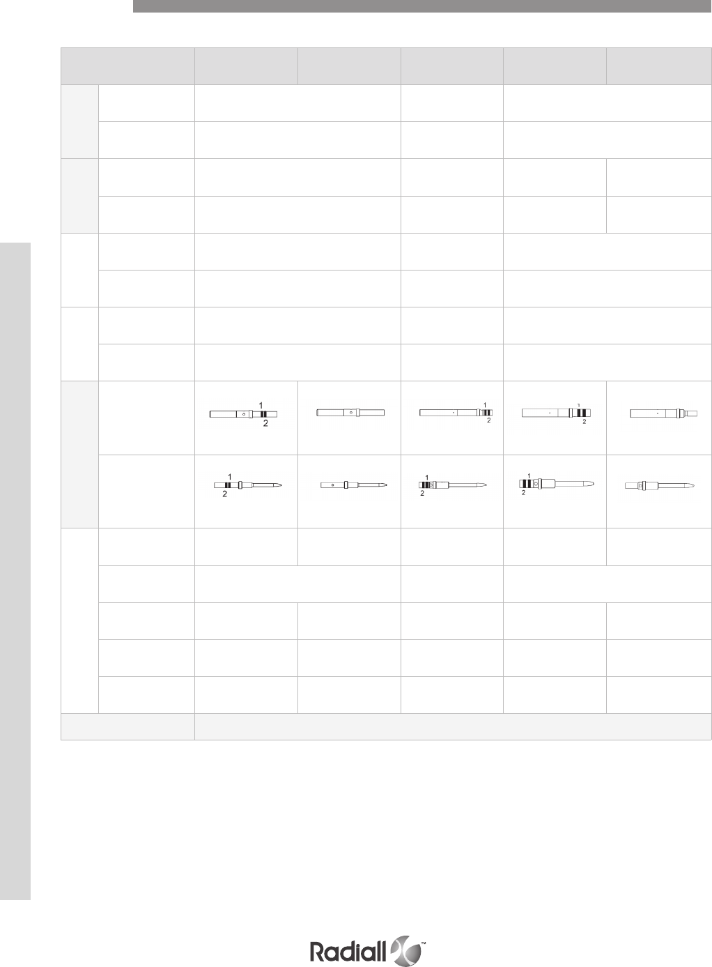
Contact size 22 22 reduced
crimp barrel 20 16 16 reduced
crimp barrel
Ins.Ext
Tool (metallic)
Radiall P/N 282885 282886 282546
Mil Spec P/N M81969/1.01 M81969/1.02 M81969/1.03
Ins.Ext
Tool (plastic)
Radiall P/N 282522 282549029 282515 -
Mil spec P/N M81969/14.01 M81969/14.02 M81969/14.03 -
Positioner
Radiall P/N 282970 282971 282972
Mil spec P/N M22520/2.23 M22520/2.08 M22520/1.02
Crimping
Tool
Radiall P/N 282281 282281 282291
Mil spec P/N M22520/2.01 M22520/2.01 M22520/1.01
Contact
Socket
620300
(1) Orange
(2) Yellow
620301 620310
(1) Orange
(2) Red
620330
(1) Orange
(2) Blue
620331
Pin
620200
(1) Orange
(2) Green
620201 620210
(1) Orange
(2) Red
620230
(1) Orange
(2) Blue
620231
Wire
Selector 4-3-3 5-4 5-6-7 6-5-4 5-4-3-2
Striping length
± .020 mm (inch) 3.5 (.138) 4 (.157) 6 (.236)
Wire outside diameter
mm (inch) 1.4 (.055) 1.2 (.047) 1.8 (.071) 2.6 (.102) 1.97 (.077)
Cross section
(mm2)0.38-0.21-0.14 0.093-0.055 0.21-0.38-0.60 1.34-0.93-0.60 0.93-0.60-0.38-0.21
Wire size
(AWG) 22-24-26 28-30 20-22-24 16-18-20 18-20-22-24
Contact arrangement See contact arrangement page 4-12 to 4-22
SIGNAL, POWER AND GROUND CONTACTS CRIMP TERMINATION
Contacts
NSX SERIES
4-34
Our Most Important Connection is with You.™
Go online for data sheets & assembly instructions. Visit www.radiall.com and enter the part number.
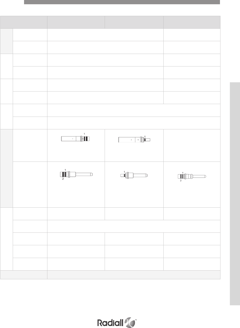
SIGNAL, POWER AND GROUND CONTACTS CRIMP TERMINATION
NOTE:
Radiall recommends plastic extraction tools for environmental cavities 22-20-16 and 12
(the metallic extraction tool leads to damage risk of triple silicon web)
Contact size 12 12 reduced crimp barrel 12
Ins.Ext
Tool (metallic)
Radiall P/N 282549004 -
Mil spec P/N M81969/28.02 M81/969/19.02
Ins.Ext
Tool (plastic)
Radiall P/N 282549004 -
Mil spec P/N M81969/14.04 -
Positioner
Radiall P/N 282972 282579
Mil spec P/N M22520/1.02 M22520/1.11
Crimping
Tool
Radiall P/N 282291
Mil spec P/N M22520/1.01
Contact
Socket
620340
(1) Orange
(2) Yellow
620341
(1) Orange
-
Pin
620240
(1) Orange
(2) Yellow
620241
(1) Orange
619240
(front release rear
removable contact)
(1) Orange
(2) Yellow
Wire
Selector 8-7-6 2-3-4-5 8-7-6
Striping length
± .020 mm (inch) 6 (.236)
Wire outside diameter
mm (inch) 3.4 (.134) 2.4 (.094) 3.4 (.134)
Cross section
(mm2)3.18-1.91-1.34 0.93-0.60-0.38-0.21 3.18-1.91-1.34
Wire size
(AWG) 12-14-16 18-20-22-24 12-14-16
Contact arrangement See contact arrangement page 4-12 to 4-22
Contacts
2
NSX SERIES
4-35
Our Most Important Connection is with You.™
Go online for data sheets & assembly instructions. Visit www.radiall.com and enter the part number.
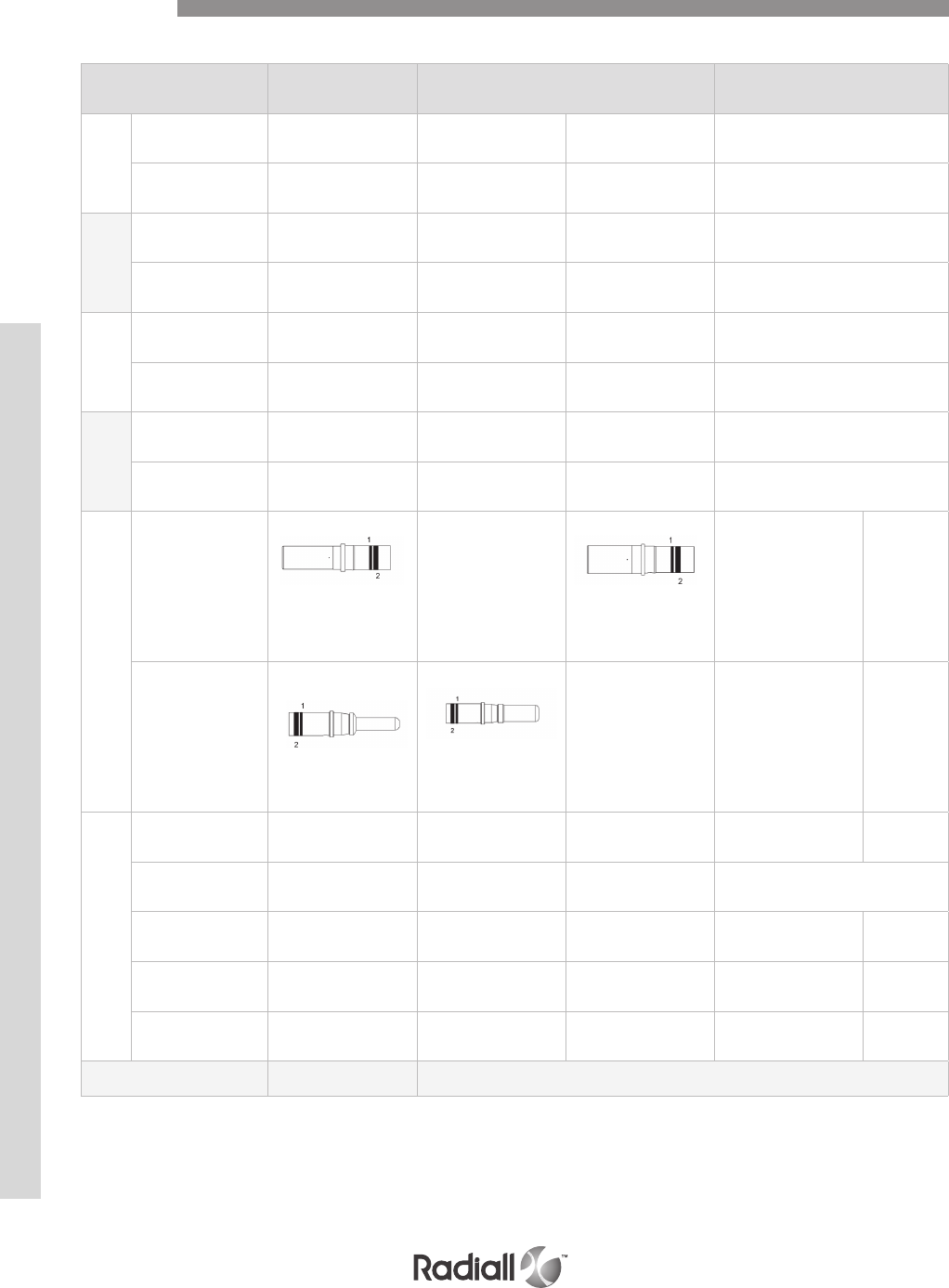
Contact size 88 grounded 5
Ext Tool
(metallic)
Radiall P/N socket: 282549001
pin: 282549012 282549012 282540001 282548
Mil spec P/N socket: M81969/28.03
pin: M81969/19.03 M81969/19.03 M81969/28.03 M81969/28.01
Positioner
Radiall P/N - - 282588 282557
Mil spec P/N M22520/23.09 M22520/23.09 - -
Die
Radiall P/N - - - -
Mil spec P/N M22520/23.02 M22520/23.02 M22520/23.02 -
Crimping
Tool
Radiall P/N --- 282296
Mil spec P/N M22520/23.01 M22520/23.01 M22520/23.01
Contact
Socket
619370
(1) Orange
(2) Brown
-
619371
(1) Orange
(2) Black
616361 616366
Pin
619270
(front release rear
removable contact)
(1) Orange
(2) Brown
619271
(front release rear
removable contact)
(1) Orange
(2) Black
-616261 616266
Wire
Selector ---1-1 8-5
Striping length
± .020 mm (inch) 11.5 (.453) 11.5 (.453) -8.0 (.315)
Wire outside diameter
mm (inch) 5.7 (.224) 5.7 (.224) -3.4 (.134) 5.7 (.234)
Cross section
(mm2)9-5 9-5 -3.18-1.91 9-5
Wire size
(AWG) 8-10 8-10 -12-14 8-10
Contact arrangement 6P6 See contact arrangement page 4-12 to 4-22
SIGNAL, POWER AND GROUND CONTACTS CRIMP TERMINATION
Contacts
NSX SERIES
4-36
Our Most Important Connection is with You.™
Go online for data sheets & assembly instructions. Visit www.radiall.com and enter the part number.
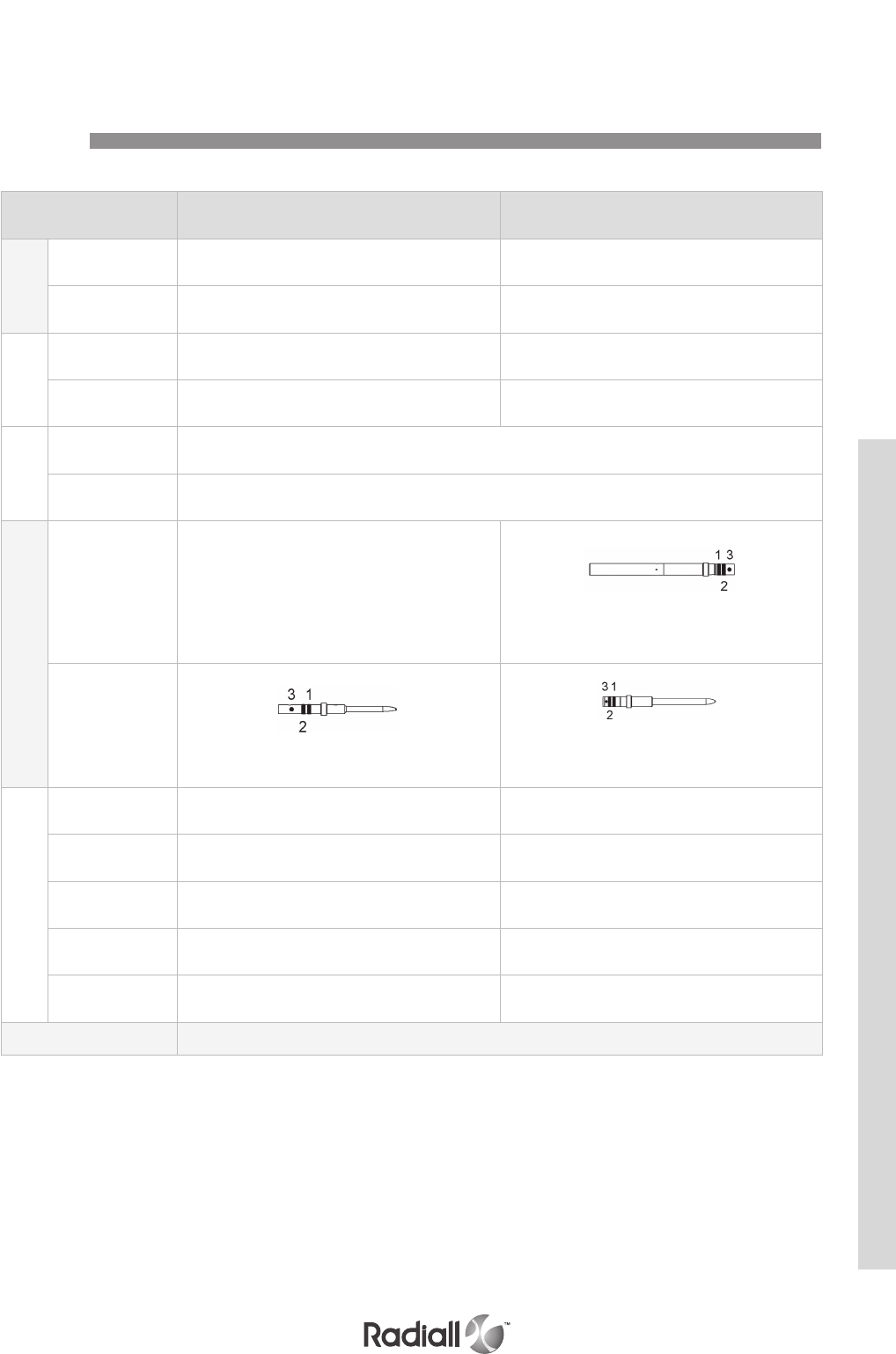
Contact size 22 20
Ins.Ext
Tool
Radiall P/N 282885 282886
Mil spec P/N M81969/1.01 M81969/1.02
Positioner
Radiall P/N 282970 282971
Mil spec P/N M22520/2.23 M22520/2.08
Crimping
Tool
Radiall P/N 282281
Mil spec P/N M22520/2.01
Contact
Socket
620380
(1) Orange
(2) Green
(3) Yellow
620390
(1) Orange
(2) Red
(3) Yellow
Pin
620280
(1) Orange
(2) Green
(3) Yellow
620290
(1) Orange
(2) Red
(3) Yellow
Wire
Selector 4-3-3 7-6-5
Striping length
± .020 mm (inch) 3.5 (.138) 4 (.157)
Wire outside diameter
mm (inch) 1.4 (.055) 1.8 (.071)
Cross section
(mm2)0.38-0.21-0.14 0.60-0.38-0.21
Wire size
(AWG) 22-24-26 20-22-24
Contact arrangement See contact arrangement page 4-12 to 4-22
CHROMEL CONTACTS – CRIMP TERMINATION
Contacts
NSX SERIES
4-37
Our Most Important Connection is with You.™
Go online for data sheets & assembly instructions. Visit www.radiall.com and enter the part number.
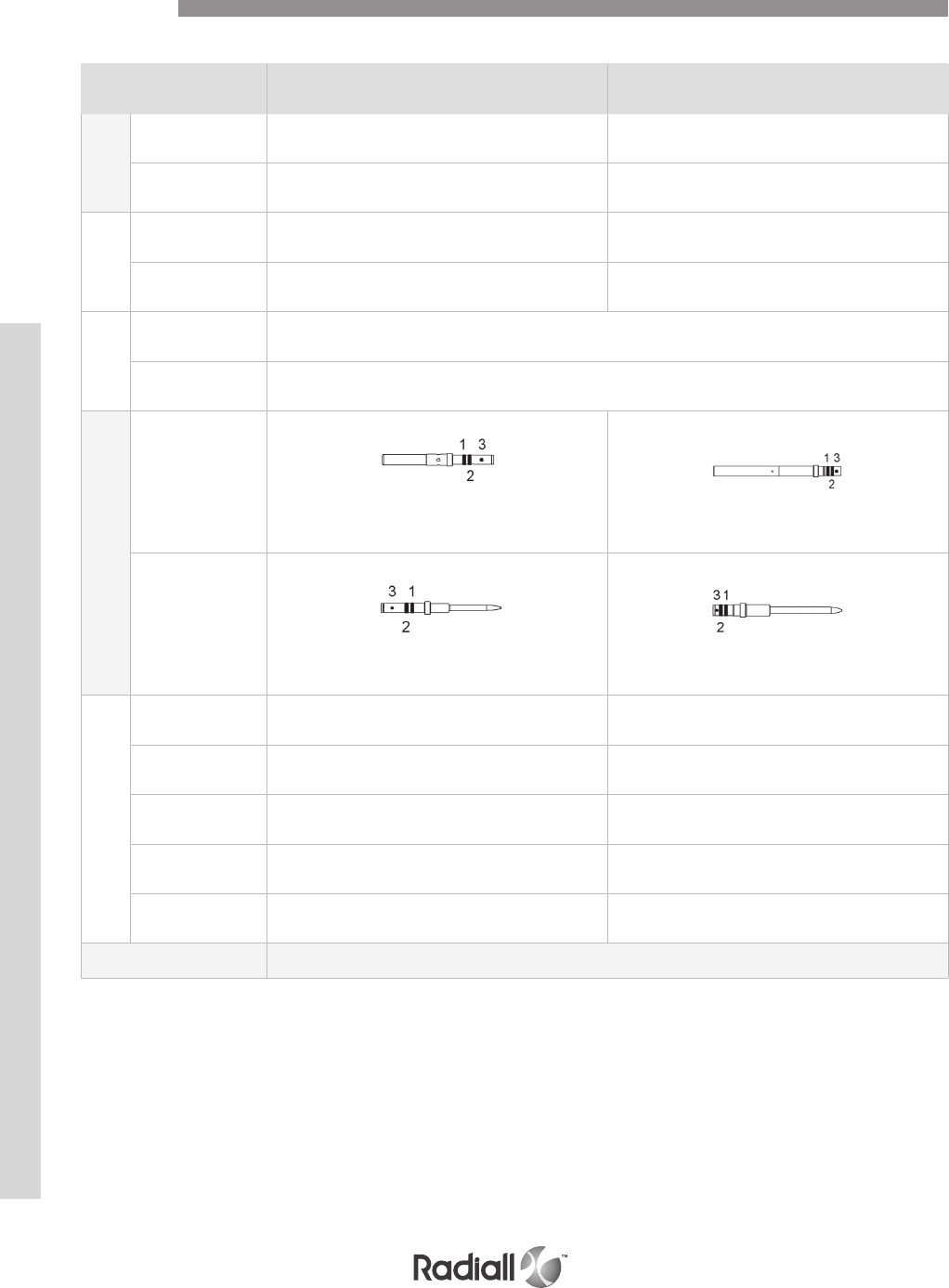
ALUMEL CONTACTS – CRIMP TERMINATION
Contacts
Contact size 22 20
Ins.Ext
Tool
Radiall P/N 282885 282886
Mil spec P/N M81969/1.01 M81969/1.02
Positioner
Radiall P/N 282970 282971
Mil spec P/N M22520/2.23 M22520/2.08
Crimping
Tool
Radiall P/N 282281
Mil spec P/N M22520/2.01
Contact
Socket
620381
(1) Orange
(2) Green
(3) Black
620391
(1) Orange
(2) Red
(3) Black
Pin
620281
(1) Orange
(2) Green
(3) Black
620291
(1) Orange
(2) Red
(3) Black
Wire
Selector 4-3-3 7-6-5
Striping length
± .020 mm (inch) 3.5 (.138) 4 (.157)
Wire outside diameter
mm (inch) 1.4 (.055) 1.8 (.071)
Cross section
(mm2)0.38-0.21-0.14 0.60-0.38-0.21
Wire size
(AWG) 22-24-26 20-22-24
Contact arrangement See contact arrangement page 4-12 to 4-22
NSX SERIES
4-38
Our Most Important Connection is with You.™
Go online for data sheets & assembly instructions. Visit www.radiall.com and enter the part number.
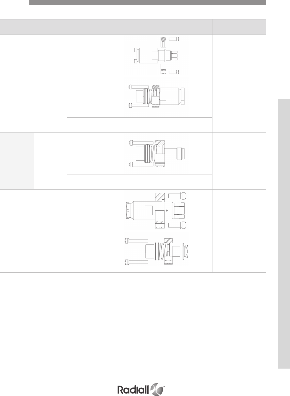
SIZE 1 COAXIAL CONTACTS
Contacts
Wire Type Part number Contact Contact
arrangements
RG 214
RG 393
Pin 620001
71C1-1C71-C2
Socket
620101
620101001 Identical to 620101
without O-ring
Not applicable
TNC termination Socket
620101003
71C1-1C71-C2
620101004 Identical to 620101003
without O-ring
RG 223
RG 142
Pin 620003
71C1-1C71-C2
Socket 620103
NSX SERIES
4-39
Our Most Important Connection is with You.™
Go online for data sheets & assembly instructions. Visit www.radiall.com and enter the part number.
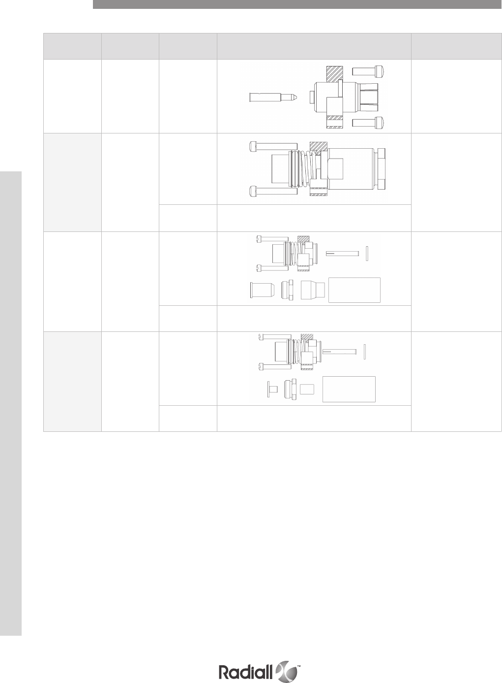
Wire Type Part number Contact Contact
arrangements
RG 402
UT .141 Pin 620005 71C1-1C71-C2
NSA 935 358 Socket
620107
71C1-1C71-C2
620107001 Identical to 620107
without O-ring
ASNE 0406 WD
and
FILECA
1 703/94
Socket
620108
71C1-1C71-C2
620108002 Identical to 620108
without O-ring
RG 400
RG 142 Socket
620109
71C1-1C71-C2
620109001 Identical to 620109
without O-ring
SIZE 1 COAXIAL CONTACTS
Contacts
NSX SERIES
4-40
Our Most Important Connection is with You.™
Go online for data sheets & assembly instructions. Visit www.radiall.com and enter the part number.
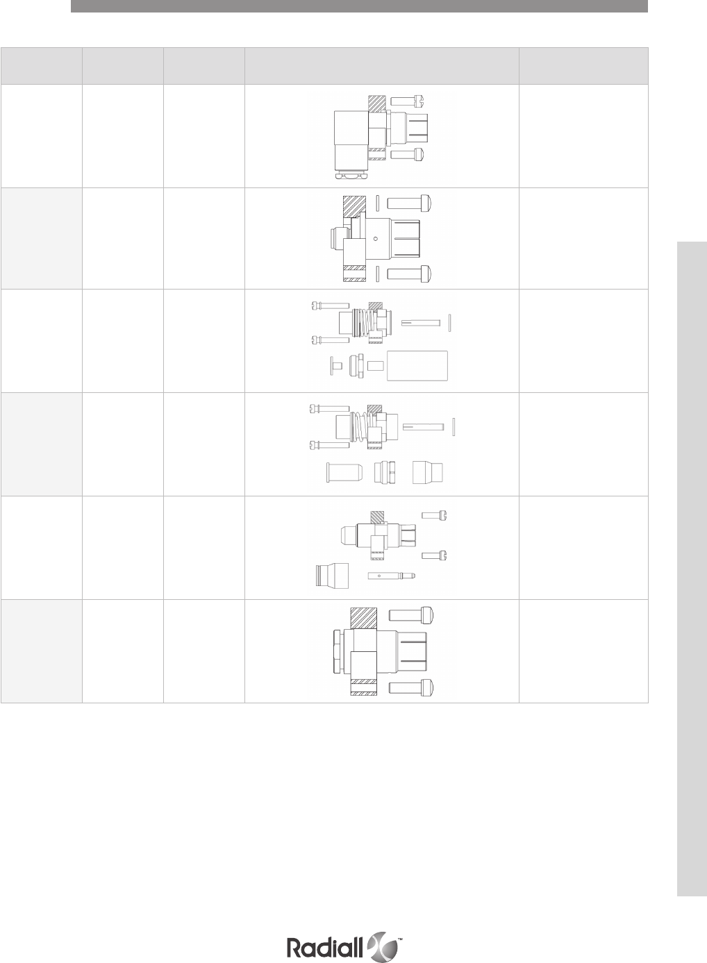
Wire Type Part number Contact Contact
arrangements
RG 142 Pin 620011 71C1-1C71-C2
Not applicable
SMA termination Pin 620044 71C1-1C71-C2
ASNE0691WM Socket 620101011 71C1-1C71-C2
ASNE0692WN Socket 620101012 71C1-1C71-C2
ASNE0692WN Pin 620001012 71C1-1C71-C2
RD316 Pin 620043001 71C1-1C71-C2
SIZE 1 COAXIAL CONTACTS
Contacts
NSX SERIES
4-41
Our Most Important Connection is with You.™
Go online for data sheets & assembly instructions. Visit www.radiall.com and enter the part number.
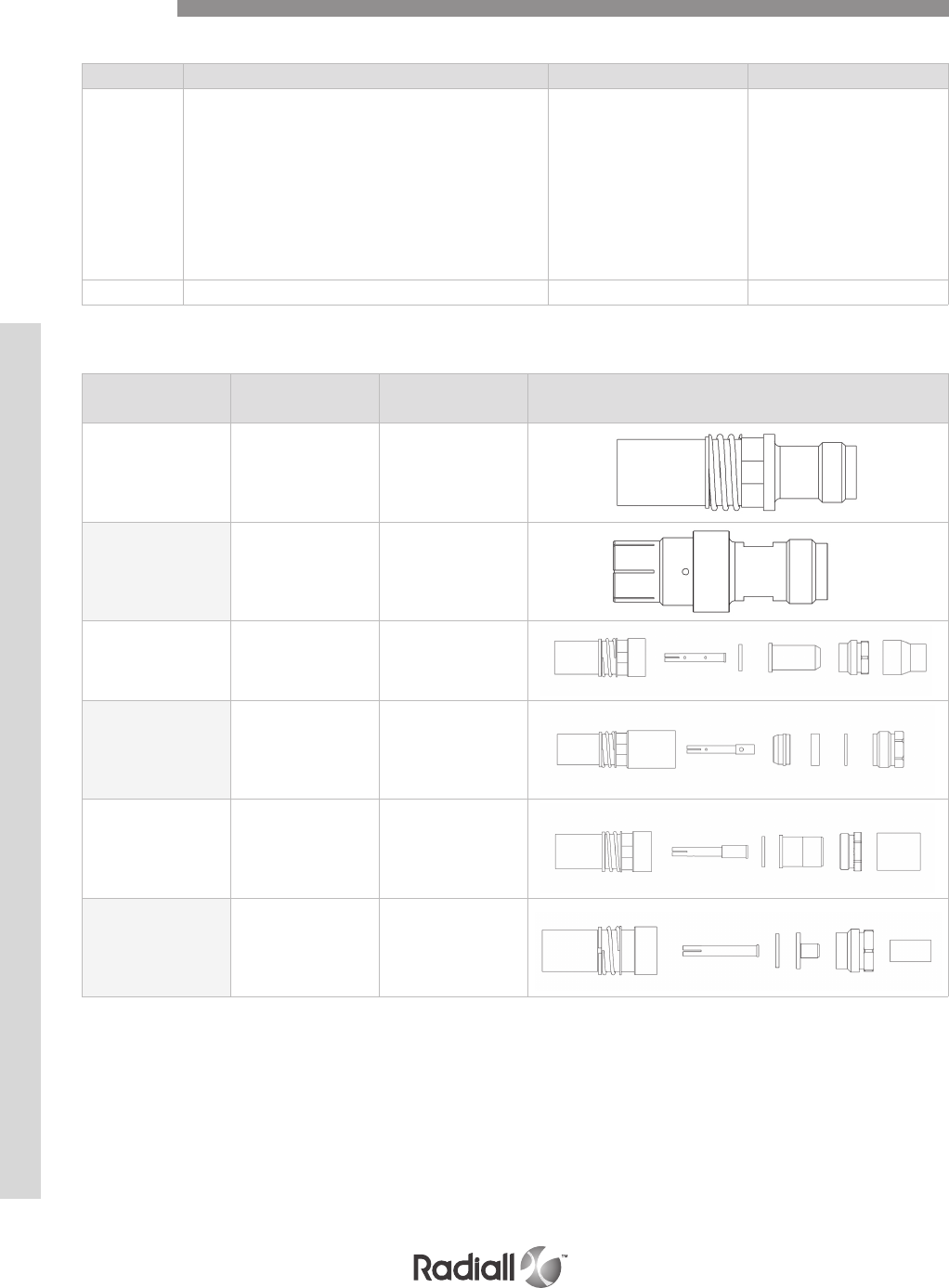
SIZE 1 RF COAXIAL CONTACTS FOR NSX T-CAS CONNECTOR
DELIVERY CODE FOR T-CAS APPLICATION
Contacts
Cable Contact type Part number Contact
TNC TERMINATION Socket 620116
TNC TERMINATION Pin 620017
ASNE 0406WD
ECS 311 201 Socket 620117
RG 225
RG 393 Socket 620119100
ECS 310801 Socket 620119102
RG 142
RG 400
TIMES AA6343
ECS 3C142B
ASNE 0293XF
Socket 620146
Code Connector details Socket contacts for plug Pin contacts for receptacle
No code
Contacts:
Size 1 RF coaxial contacts to be ordered separately.
Inserts:
For plug:
- Mating side insert: thermoplastic.
- Size 1 RF coax retention plate: stainless steel.
For receptacle:
- Aluminum alloy nickel plated.
620117
620146 620049
N Connector delivered with coaxial contacts 620116 620049
NSX SERIES
4-42
Our Most Important Connection is with You.™
Go online for data sheets & assembly instructions. Visit www.radiall.com and enter the part number.
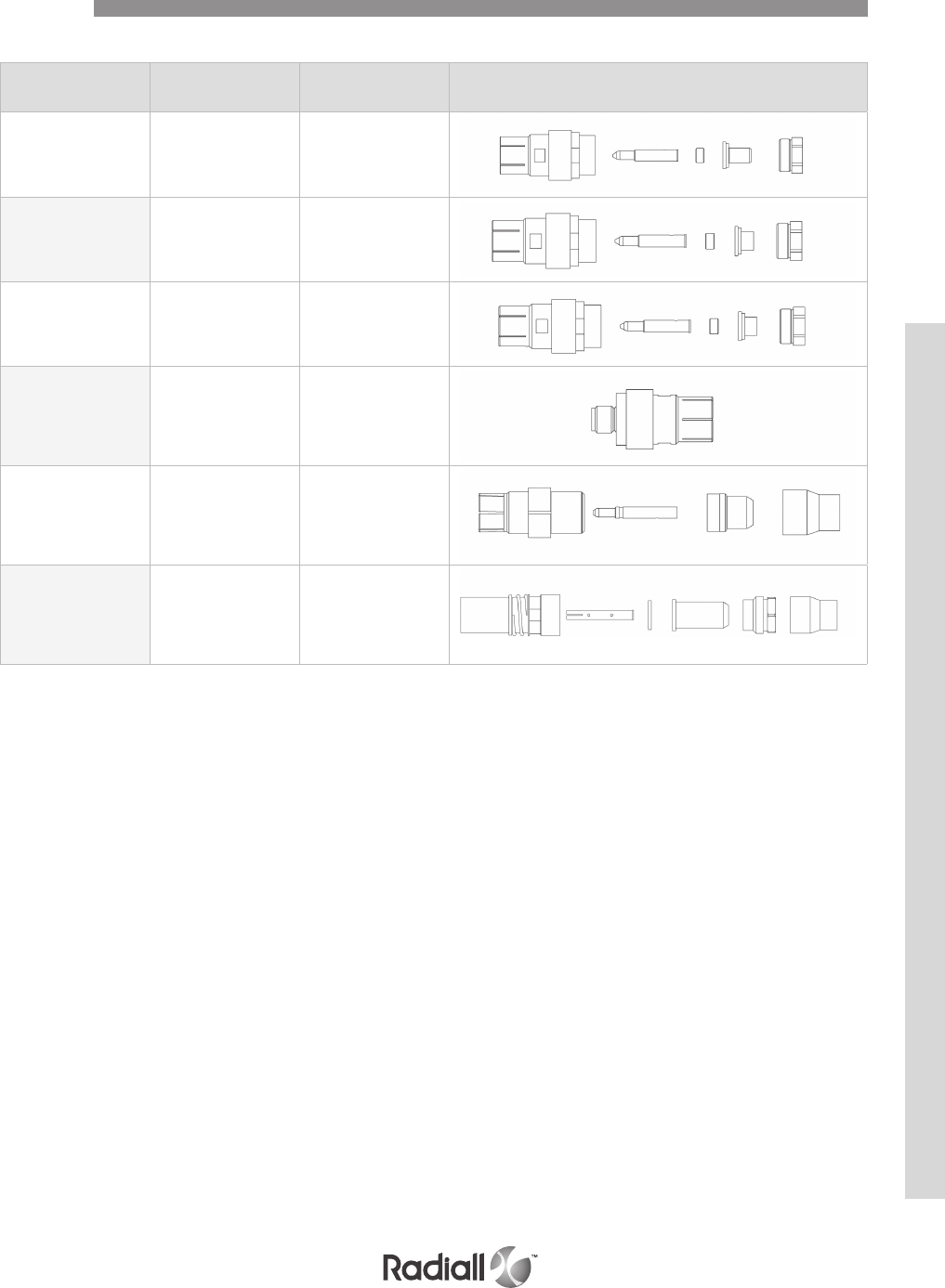
Cable Contact type Part number Contact
RG 142 Pin 620046
UT 141 Pin 620047
UT .085 Pin 620047010
SMA TERMINATION Pin 620049
ASNE0692WN-
ASNE0406WD Pin 620019105
ASNE0692WN Socket 620119105
SIZE 1 RF COAXIAL CONTACTS FOR NSX T-CAS CONNECTOR
Contacts
NSX SERIES
4-43
Our Most Important Connection is with You.™
Go online for data sheets & assembly instructions. Visit www.radiall.com and enter the part number.
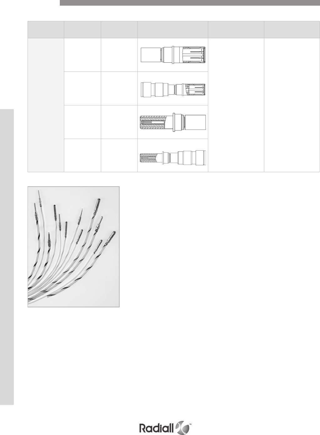
Wire Type Part number Contact For insert Ins/Ext Tool
RG142
RG400
RG412
RG223
RG55U
ASNE0293XF
Socket 619051
For all size 8 cavities 282549001
(M81969/28.03)
Socket 619051001
environmental
Pin 619151
Pin 619151001
environmental
SIZE 8 COAXIAL CONTACTS
Contacts
NSX SERIES
4-44
Our Most Important Connection is with You.™
Go online for data sheets & assembly instructions. Visit www.radiall.com and enter the part number.
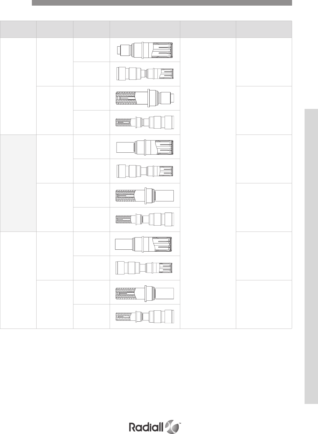
Wire Type Part number Contact For insert(1) Ins/Ext Tool
RG316-KX22
-RG179
ASNE0639XY
Socket
619054
for all size 8 cavities
282549001
(M81969/28.03)
619054001
environmental
Pin
619154
-
619154001
environmental
Gore
GSC-03-8174
8-00
Socket
619053
282549001
(M81969/28.03)
619053001
environmental
Pin
619153
-
619153001
environmental
RG180
RG195
Socket
619052
282549001
(M81969/28.03)
619052001
environmental
Pin
619152
-
619152001
environmental
SIZE 8 COAXIAL CONTACTS
NOTE:
(1) Except for inserts 6T6 and 10T10
Contacts
NSX SERIES
4-45
Our Most Important Connection is with You.™
Go online for data sheets & assembly instructions. Visit www.radiall.com and enter the part number.
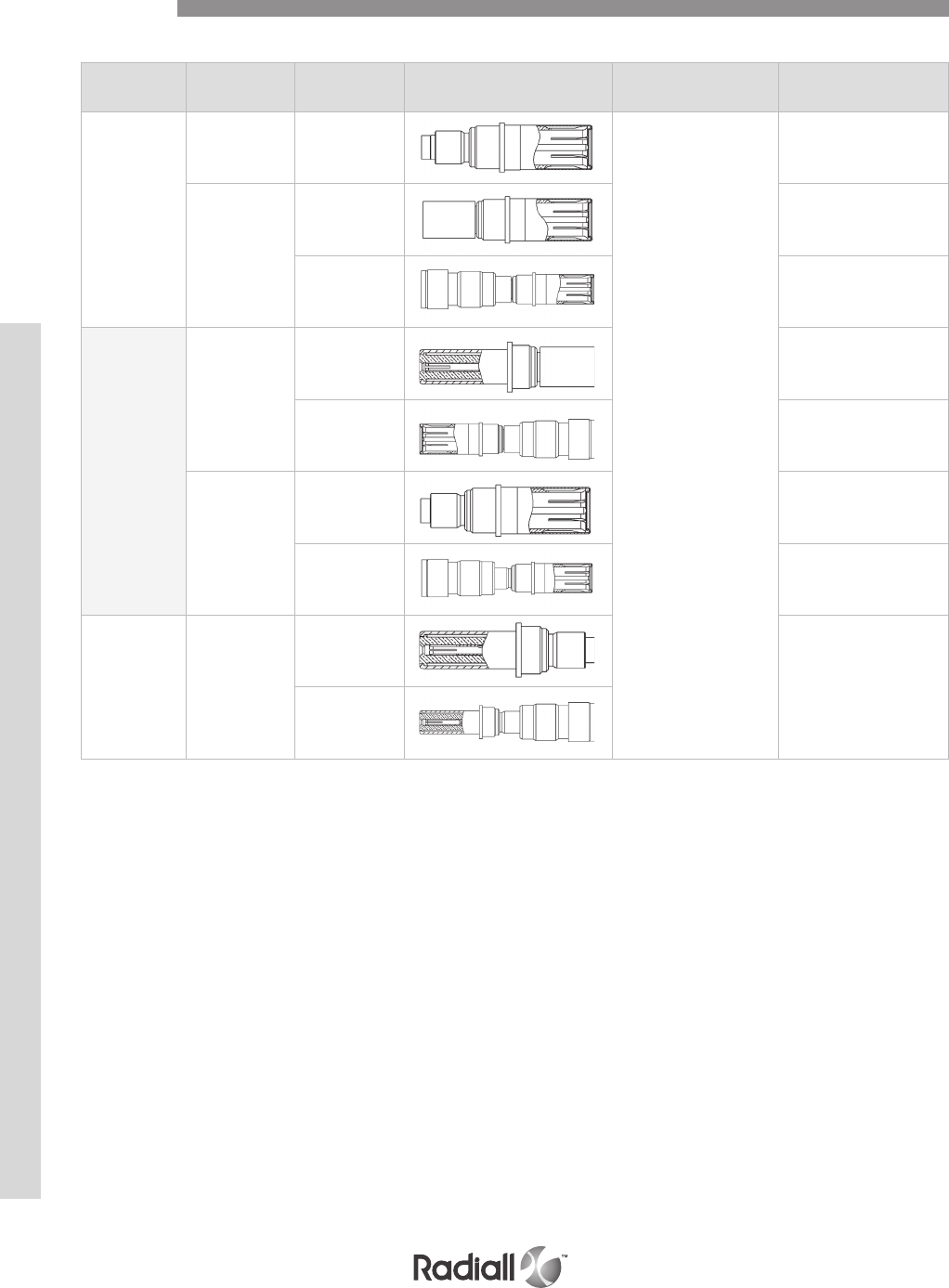
Wire Type Part number Contact For insert(1) Ins/Ext Tool
ASNE0690WL
Socket 619054002
for all size 8 cavities
282549001
(M81969/28.03)
Socket
619050 -
619050001
environmental -
RG58
RG141
Pin
619150 -
619150001
environmental -
Socket
619055 -
619055001
environmental -
RG178
KX21
ASNE0633WG
Pin
619155
-
619155001
environmental
SIZE 8 COAXIAL CONTACTS
NOTE:
(1) Except for inserts 6T6 and 10T10.
Contacts
NSX SERIES
4-46
Our Most Important Connection is with You.™
Go online for data sheets & assembly instructions. Visit www.radiall.com and enter the part number.
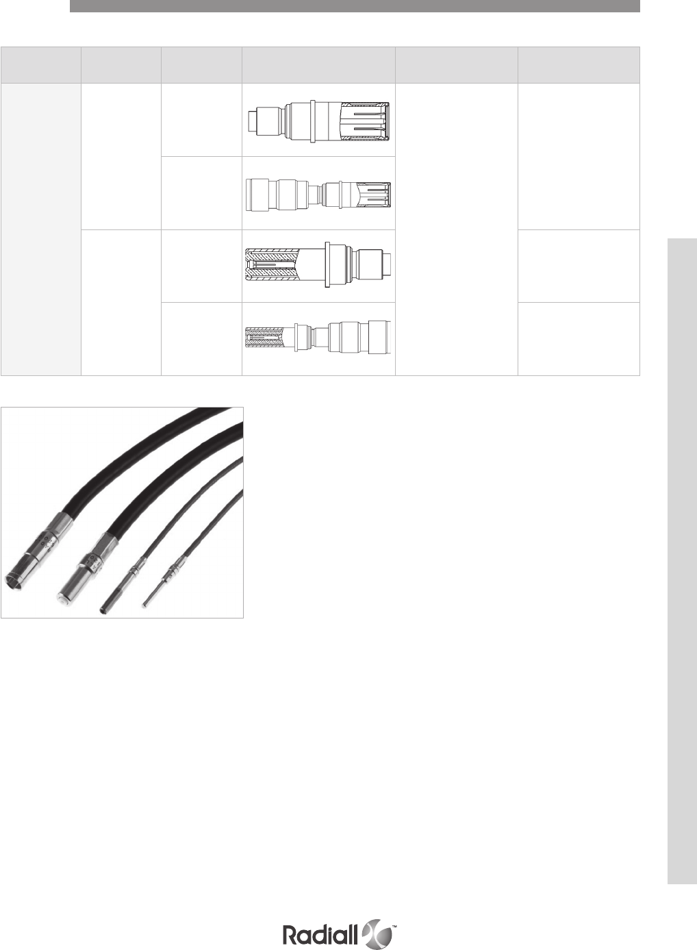
Wire Type Part number Contact For insert(1) Ins/Ext Tool
RG316
Socket
619056
For all size 8 cavities
-
-
619056001
environmental
Pin
619156 -
619156001
environmental -
SIZE 8 COAXIAL CONTACTS
NOTE:
(1) Except for inserts 6T6 and 10T10
Contacts
NSX SERIES
4-47
Our Most Important Connection is with You.™
Go online for data sheets & assembly instructions. Visit www.radiall.com and enter the part number.
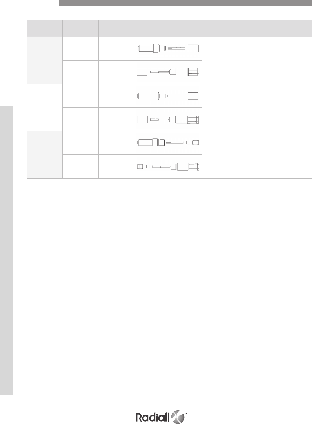
Wire Type Part number Contact For insert Ins/Ext Tool
RG 58
RG 141
Pin 620120*
for all size 5 cavities
282946
(M81969/28.01)
Socket 620020*
RG 142
RG 223
RG 400
Pin 620121*
282946
(M81969/28.01)
Socket 620021*
ASNE0639XY
RG 179
RG 316
KX 22
Pin 620122*
282946
(M81969/28.01)
Socket 620022*
SIZE 5 COAXIAL CONTACTS
*Add 001 to these P/N to order for environmental contacts.
Contacts
NSX SERIES
4-48
Our Most Important Connection is with You.™
Go online for data sheets & assembly instructions. Visit www.radiall.com and enter the part number.
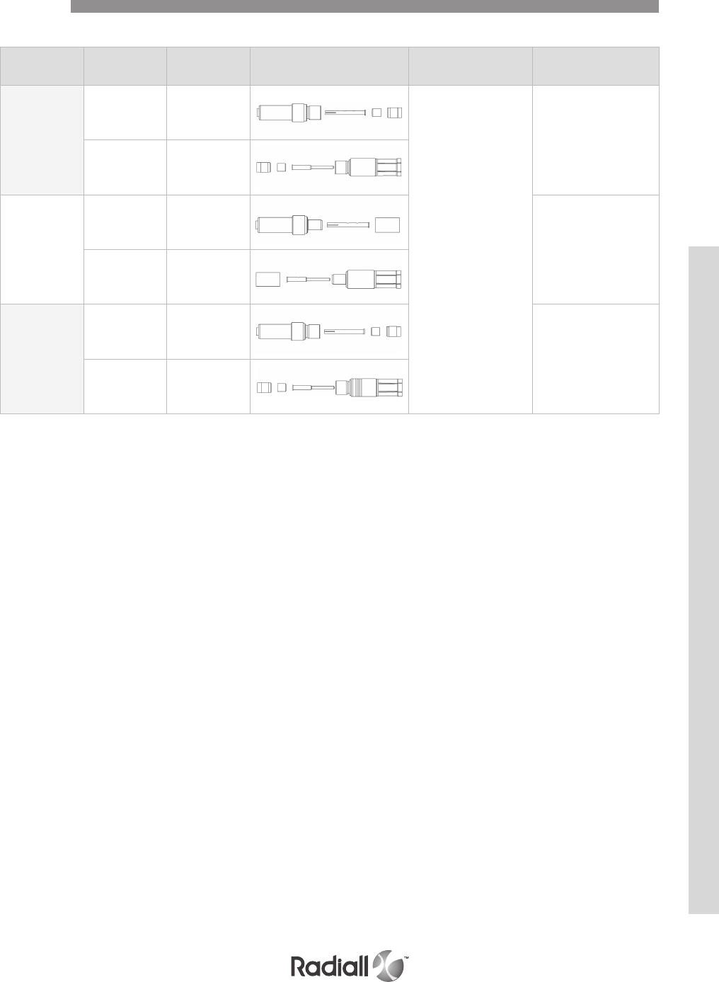
Wire Type Part number Contact For insert Ins/Ext Tool
ASNE 0633WG
RG 178
KX 21
Pin 620123*
for all size 5 cavities
282946
(M81969/28.01)
Socket 620023*
RG 180
RG 195
Pin 620124*
282946
(M81969/28.01)
Socket 620024*
RD 316
Pin 620129*
282946
(M81969/28.01)
Socket 620029*
SIZE 5 COAXIAL CONTACTS
*Add 001 to these P/N to order for environmental contacts
Contacts
NSX SERIES
4-49
Our Most Important Connection is with You.™
Go online for data sheets & assembly instructions. Visit www.radiall.com and enter the part number.
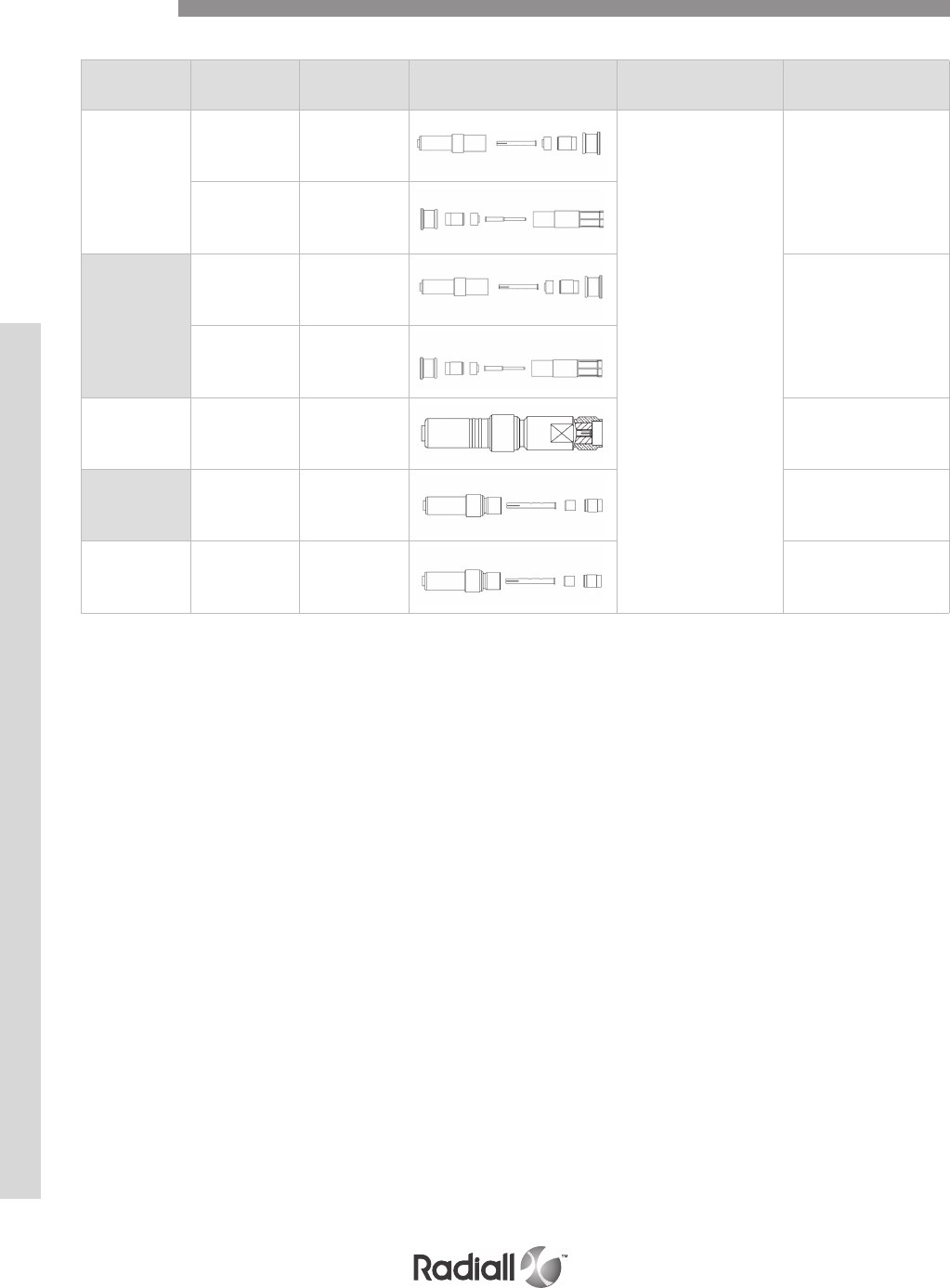
Wire Type Part number Contact For insert Ins/Ext Tool
ADAMS-
RUSSEL
FC 11Z (per
S280W503-1)
Pin 620182001
for all size 5 cavities
282946
(M81969/28.01)
Socket 620082001
ADAMS-
RUSSEL
FC 14Z (per
S280W503-2)
Pin 620183001
282946
(M81969/28.01)
Socket 620083001
SMA
Termination Pin 620134 282946
(M81969/28.01)
ASNE0690WL Pin 620184 282946
(M81969/28.01)
ASNE0690WL Socket 620084 282946
(M81969/28.01)
SIZE 5 COAXIAL CONTACTS
Contacts
NSX SERIES
4-50
Our Most Important Connection is with You.™
Go online for data sheets & assembly instructions. Visit www.radiall.com and enter the part number.
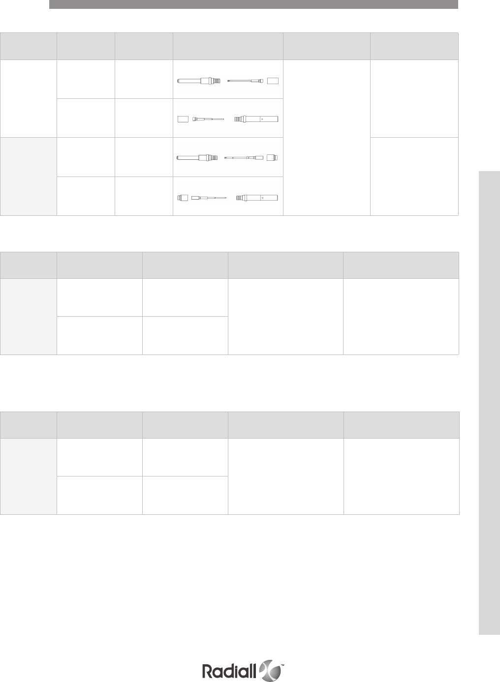
Wire Type Part number Contact For insert Ins/Ext Tool
KX22
RG 316
RG 179
ASNE0639XY
ASNE0632WK
ASNE0752WS
Pin 618150
for all size 16 cavities
282892
Socket 618050
RG 178
KX 21
ASNE0633WG
Pin 618154
282892
Socket 618054
SIZE 16 COAXIAL CONTACTS
Wire Type Part number For insert Ins/Ext Tool
EN 3375-006
ASNE 0290XM
Pin 620167001
15T6Q2 (M81969/14-05)
Socket 620067001
SIZE 10 CONCENTRIC TWINAX CONTACTS
Wire Type Part number For insert Ins/Ext Tool
MIL C
17/17600002
Pin 616195001(1)
for all size 5 cavities 282946
(M81969/28.01)
Socket 616095001(2)
SIZE 5 CONCENTRIC TWINAX CONTACTS
(1) 616195001 contact environmental version is 616195009
(2) 616095001 contact environmental version is 616095009
Contacts
NSX SERIES
4-51
Our Most Important Connection is with You.™
Go online for data sheets & assembly instructions. Visit www.radiall.com and enter the part number.

NOTE:
(1) FR/RR contacts are compatible with 6T6 and 10T10 inserts.
Wire Type Part number Contact For insert Ins/Ext Tool
Tensolite
(S280W502-1)
Pin 619165
for all size 8 cavities
282549001
(M81969/28.03)
Socket 619065
Pin 619166(1)
FR/RR
282549001
(M81969/28.03)
for ins.
282549012
(M81969/28.03)
for ext.
MIL C
17/17600002
Pin 619169001
282549001
(M81969/28.03)
Socket
619069001
619069002
environmental
SIZE 8 CONCENTRIC TWINAX CONTACTS
Contacts
NSX SERIES
4-52
Our Most Important Connection is with You.™
Go online for data sheets & assembly instructions. Visit www.radiall.com and enter the part number.
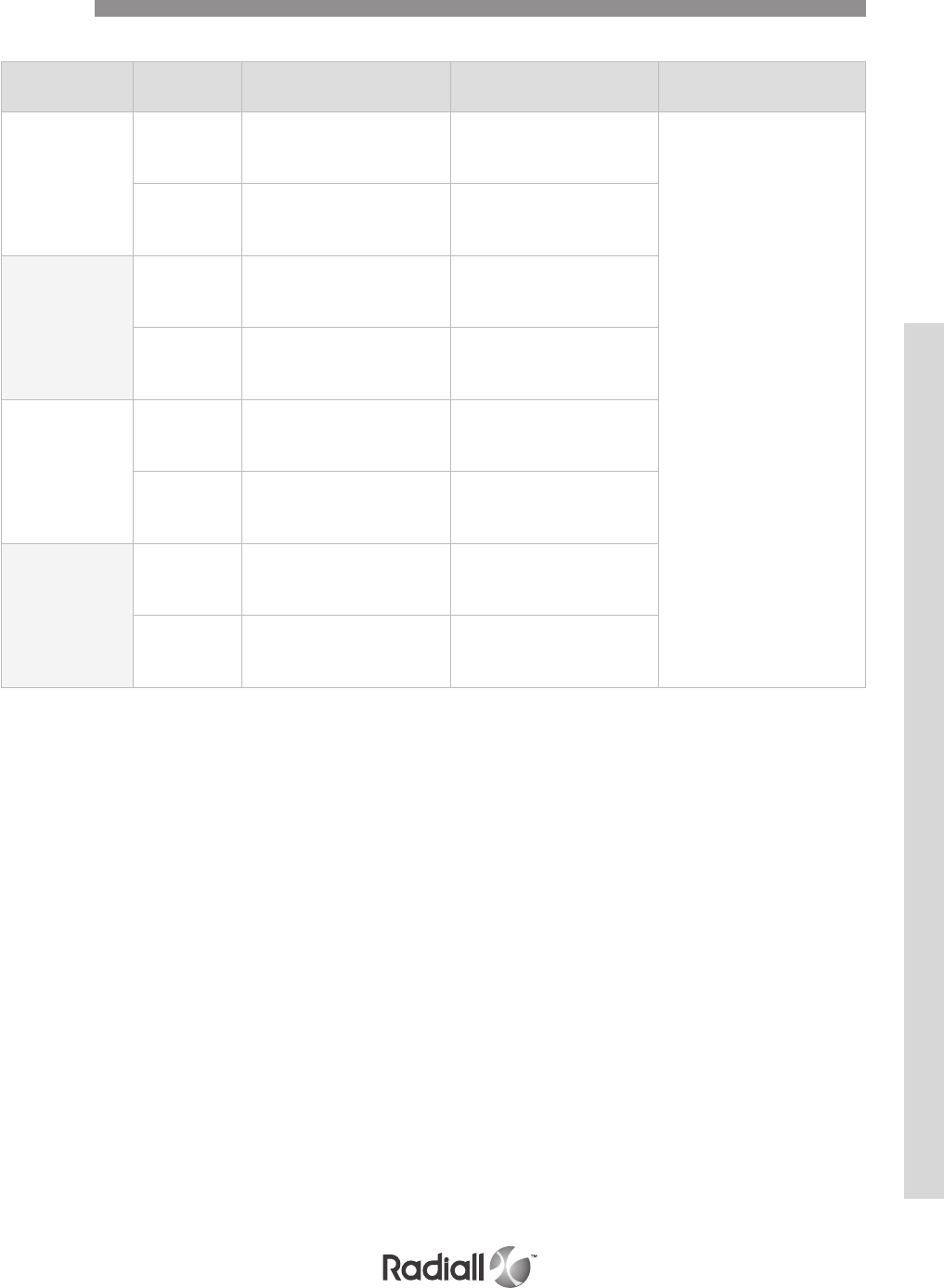
Wire Type Part number
(non environmental)
Part number
(environmental) Ins/Ext Tool
ABS1503KD24
(110 Ω)
Pin 620175010 620175011
282549001
(M81969/28.03
or M81969/14.06)
Socket 620075010 620075011
THERMAX
956S-4T200
GORE RCN8422
(110 Ω)
Pin 620179002 620179001
Socket 620079002 620079001
TENSOLITE
NF24Q100 (100 Ω)
Pin 620175050 620175051
Socket 620075050 620075051
TENSOLITE
NF26Q100
JSFY 18
Pin 620175021 620175020
Socket 620075021 620075020
SIZE 8 QUADRAX CONTACTS
Contacts
NSX SERIES
4-53
Our Most Important Connection is with You.™
Go online for data sheets & assembly instructions. Visit www.radiall.com and enter the part number.
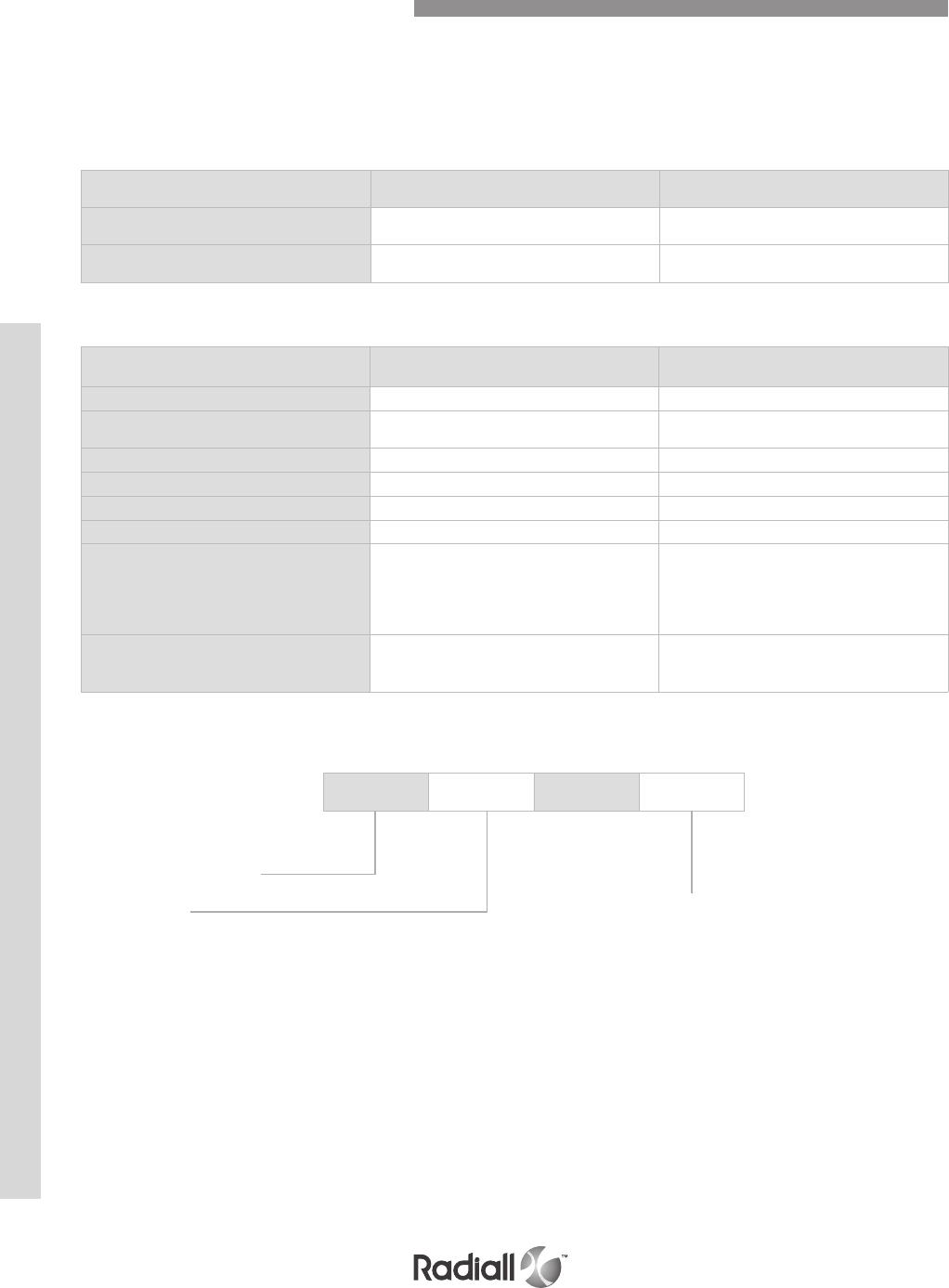
The LuxCis® product range is a proven, flexible and always expending fiber optic interconnect
solution offering high speed communication in aerospace and other harsh environments.
NOTE:
Radiall can support you with your cable and harness assemblies.
Please contact your sales representative.
OPTICAL PERFORMANCES
LUXCIS® CONTACTS
MECHANICAL AND ENVIRONMENTAL CHARACTERISTICS
MultiMode (PC)
850 / 1300 nm
SingleMode (UPC)
1310 / 1550 nm
Insertion Loss (IL) Mean
(IEC 61300-3-4 Method B)
0.1 dB 0.15 dB
Return Loss (RL)
(IEC 61300-3-6)
> 20 dB > 50 dB
Standard Performances
Thermal cycling
SAE AS 13441 method 1003.1 -55°C/+125°C (cable dependant)
Temperature
endurance
TIA/EIA 455-4 1000 h @ 125°C (cable dependant)
Vibration
TIA/EIA 455-11 16.4 Grms
Shocks
TIA/EIA 455-14 50 G, 11 ms
Durability
TIA / EIA 364-09 500 cycles
Maintenance ageing
SAE AS 13441 method 2002.1 10 cycles
Cable retention
Cable retention
1.8 mm diameter
900 µm diameter
SAE AS 13441 method 2009.1 68 N
7 N
Humidity TIA EIA 455-5
10 cycles / 24 h
90% RH
-25°C / +65°C
LUXCIS® CONTACTS PART NUMBERING SYSTEM
F725 0 03 419
Cable type and diameter
118:
900 µm cable
318: 1.2 mm cable with strengthening
members, tight structure
419: 1.6 to 2.2 mm cable, loose structure
519: 1.6 to 2.2 mm cable, tight structure
F725 : LuxCis® series
Ferrule type
00:
PC ferrule for SingleMode fiber
03: PC ferrule for 50/125 or 62,5/125 um MultiMode fiber
04: PC ferrule for 100/40 um MultiMode fiber
05: PC ferrule for 200/230 um MultiMode fiber
50: APC ferrule for SingleMode fiber
Fiber Optic Contacts and Accessories
NSX SERIES
4-54
Our Most Important Connection is with You.™
Go online for data sheets & assembly instructions. Visit www.radiall.com and enter the part number.
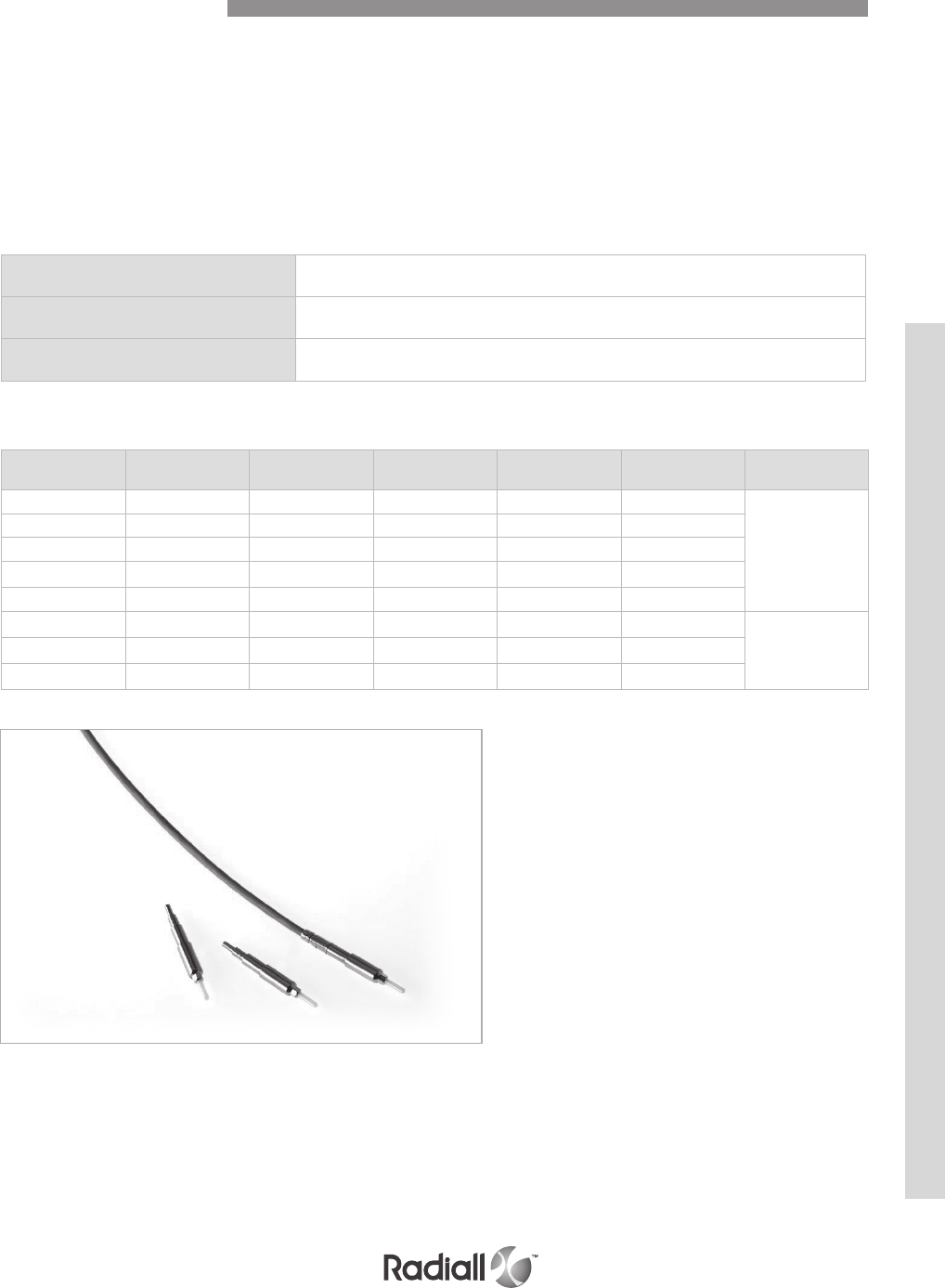
Insertion Loss (IL) 0.8 dB typical
Durability Up to 500 mating cycles
Thermal cycling -65°C / +125°C (cable dependent)
MIL-PRF-29504 fiber optic termini were developed several decades ago and are described
several MIL standard documents. They fit into standard electrical cavities and do not
require specific inserts. However, standard electrical connectors are not optimized for
optical connections with small core fibers and MIL-PRF-29504 fiber optic termini show
lower optical performances than more recent designs, such as the LuxCis®.
MIL-PRF-29504 fiber optic termini can replace MIL-PRF-29504/6
pin and MIL-PRF-29504/7 socket termini.
NOTE:
Radiall can support you with your cable and harness assemblies. Please contact your sales representative
PERFORMANCES
MIL-PRF-29504 TYPE CONTACTS PART NUMBERING SYSTEM
Contact size Pin contact
part number
Socket contact
part number
Fiber diameter
(µm)
Cable diameter
(mm) Ferule material Insertion /
Extraction tool
16 F724 004 000 F724 104 000 125 1.5 Ceramic
282515
16 F724 012 000 F724 111 000 125 1.8 Ceramic
16 F724 010 000 F724 109 000 125 2Ceramic
16 F724 001 000 F724 101 000 140 1.5 Ceramic
16 F724 040 000 F724 140 000 230 2Metallic
12 F724 204 000 F724 304 000 125 1.5 Ceramic
28254900412 F724 242 000 F724 342 000 125 1.8 Ceramic
12 F724 203 000 F724 303 000 140 1.5 Ceramic
MIL-PRF-29504 Contacts
NSX SERIES
4-55
Our Most Important Connection is with You.™
Go online for data sheets & assembly instructions. Visit www.radiall.com and enter the part number.
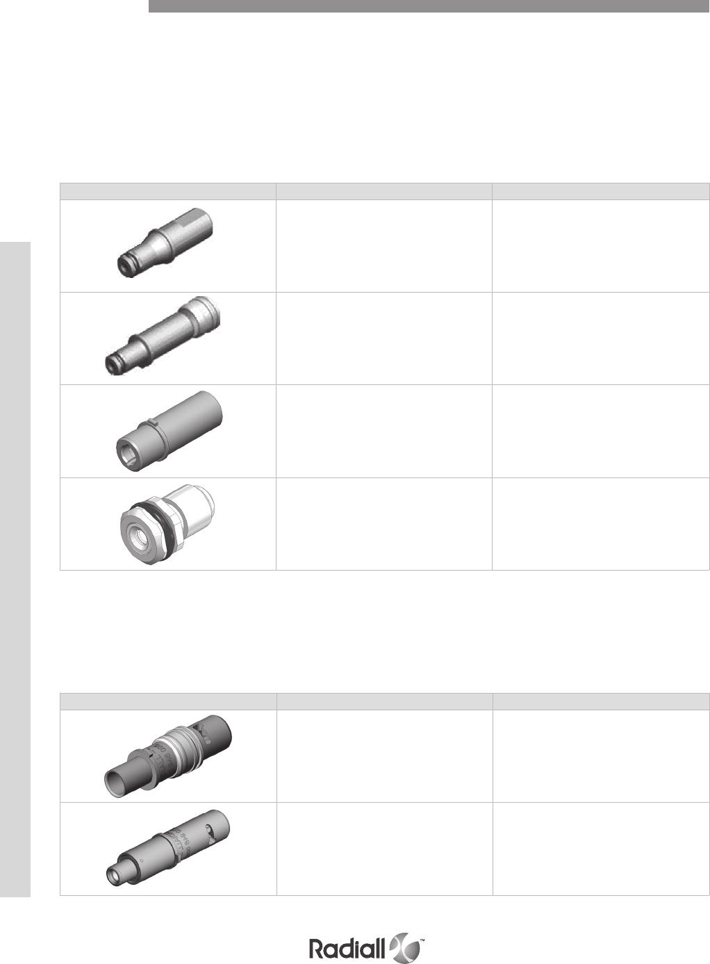
Adapters for NSX connectors’ cavities allow evolution of your existing connectors. Now, you can
get high speed connection with a connector that used to be equipped with Quadrax contacts.
Quadrax-LuxCis® adapters will turn a size 8 Quadrax cavity into a LuxCis® cavity.
This solution offers the following characteristics:
- Compliant with any ARINC 600 Quadrax cavity
- Compatible with ML and MT LuxCis® designs
- Available for multimode application
- Compatible with Quadrax insertion and extraction tool
QUADRAX - LUXCIS® ADAPTER
Part number Description
620946001 Pin quadrax adapter for LuxCis® contact in
quadrax FR type cavity with sleeveholder
620946002 Pin quadrax adapter for LuxCis® contact in
quadrax RR type cavity with sleeveholder
620946003 Socket quadrax adapter for LuxCis® contact in
quadrax RR type cavity
620946004 Sleeve holder for pin quadrax adapter
Part number Description
620946005 Pin quadrax adapter for EN4531 contact
620946006 Socket quadrax adapter for EN4531 contact
Quadrax-EN4531 adapter will help you turning a size 8 Quadrax cavity into
a EN4531 fiber optic link with the following characteristics:
- Arinc 600 compliant
- EN4626 compliant
- Compatible with all EN4531 contacts
EN 4531-101 (ABS 1379) ADAPTER FOR QUADRAX SIZE 8 CAVITY
Accessories
NSX SERIES
4-56
Our Most Important Connection is with You.™
Go online for data sheets & assembly instructions. Visit www.radiall.com and enter the part number.
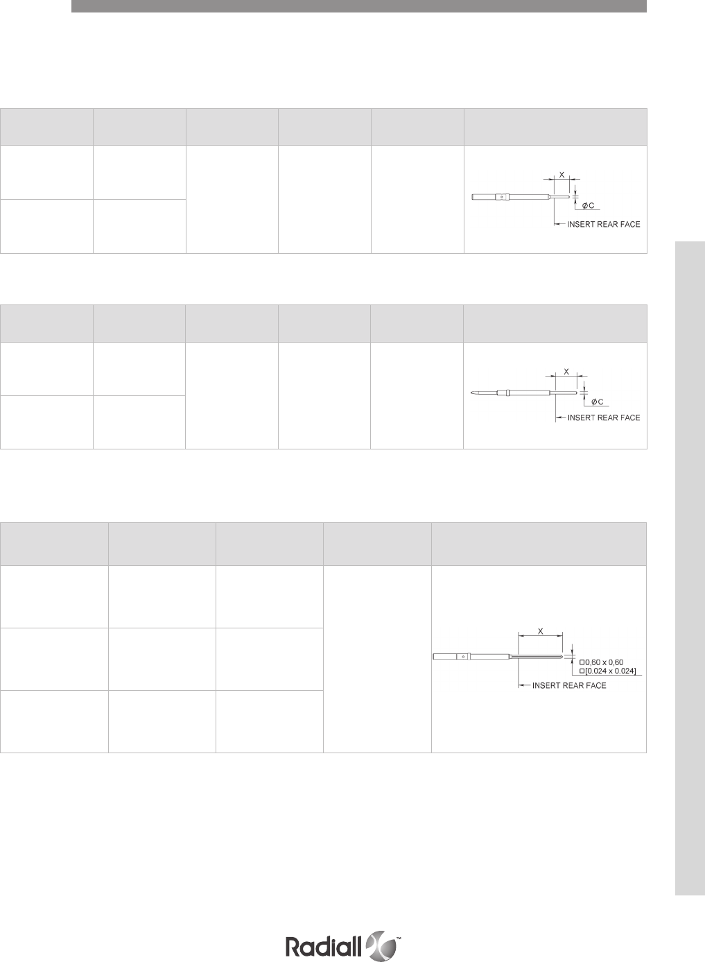
NSX E/N/H/C – REAR REMOVABLE CONTACTS
Part number Contact termination Dimension X
mm (inch)
C dia.
mm (inch) Ins/Ext Tool Figure
620 305 YA
5.20 (.205)
4.20 (.165) 0.635 (.025) 282890
620305005 ZA
Part number Contact termination Dimension X
mm (inch)
C dia.
mm (inch) Ins/Ext Tool Figure
620 202 Y
7.30 (.288)
6.30 (.250) 0.635 (.025) 282890
620202005 Z
SIZE 22 PIN CONTACTS
Part number Contact termination Dimension X
mm (inch) Ins/Ext Tool Figure
620302 K7.70 (.303)
6.30 (.248)
282890
620303 V10.70 (.421)
9.30 (.366)
620308 W12.30 (.484)
13.70 (.540)
SIZE 22 SOCKET CONTACTS
Contacts
REAR REMOVABLE WIRE WRAP CONTACTS
REAR REMOVABLE PC TAIL CONTACTS
SIZE 22 SOCKET CONTACTS
NSX SERIES
4-57
Our Most Important Connection is with You.™
Go online for data sheets & assembly instructions. Visit www.radiall.com and enter the part number.
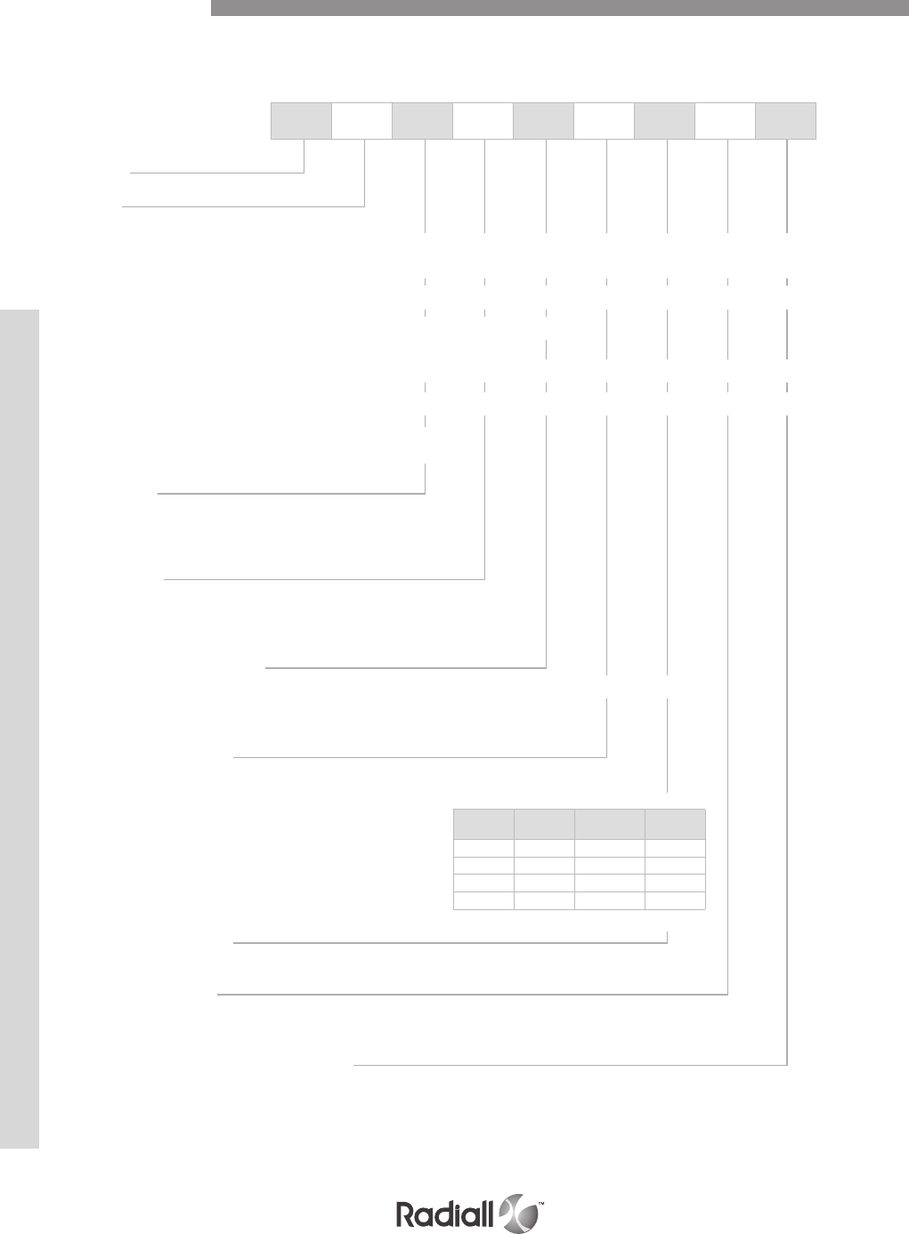
NSX F 3 R 301 Y 00 01 -
NOTES:
(1) Polarization code 00, the connector is delivered without polarizing hardware.
Polarization code from 01 to 216, the connector is delivered with the polarization hardware assembled as defined by the code see page 4-31
NSX F/G/K – CONNECTORS FOR FRONT REMOVABLE CONTACTS
Signal PC Tail contacts defined by termination code are delivered installed.
Coaxial twinax and quadrax contacts are ordered separately.
How to Order
PC tail contacts
RoHs Gold Pre-tinned Length
(inch)
RA YA ZA .150
R Y Z .250
RB YB ZB .375
RC YC ZC .500
Series
Class
F: Receptacle connectors, non-environmental
Only size 22 insert cavities can be delivered in FR/FR PC tails or wire wrap contacts.
Other insert cavities, if equipped with signal and power contacts in sizes 20, 16 and 12, will be delivered in
RR/RR crimp version.
Coaxial, twinax and quadrax contacts shall be ordered separately as RR/RR crimp contacts
G: Receptacle connectors, non-environmental
Every insert cavities will be delivered in FR/FR PC tail contacts only.
Size 1 contact will be delivered in RR/RR crimp version.
Coaxial, twinax and quadrax contacts shall be ordered separately as FR/FR PC tail contacts.
K: Receptacle connectors, non-environmental
Only combinations including inserts 100 and 150 are available in class K. Inserts 100 and 150 will be fully
populated with size 22 harpooned contacts.
With class K, use PC tail contacts termination Y.
Other inserts will be populated as per class G.
Shell size
1: 3 small cavities
2: 3 large cavities
3: 6 large cavities
Shell style
R: Alodine 1200 plated receptacle
F: Nickel plated receptacle
S: RoHS chromatation plated receptacle
Insert combination code
See combination code pages 4-22 to 4-28 and contacts arrangement pages 4-12 to 4-21
T-cas application combination code : 310 (see page 4-25)
Contact termination
Without contacts
X: Without contacts
Wire wrap
K: Wire wrap contact, 1 level (1 = .272)
V: Wire wrap contact, 2 levels (1 = .390)
W: Wire wrap contact, 3 levels (1 = .524)
L: Wire wrap contact, 4 levels (1 = .660)
Modification code (1)
See pages 4-29 to 4-30
Polarization code
See pages 4-31 to 4-33
Without code: polarization hardware is delivered unassembled
Delivery code for T-CAS application
See page 4-42
NSX SERIES
4-58
Our Most Important Connection is with You.™
Go online for data sheets & assembly instructions. Visit www.radiall.com and enter the part number.
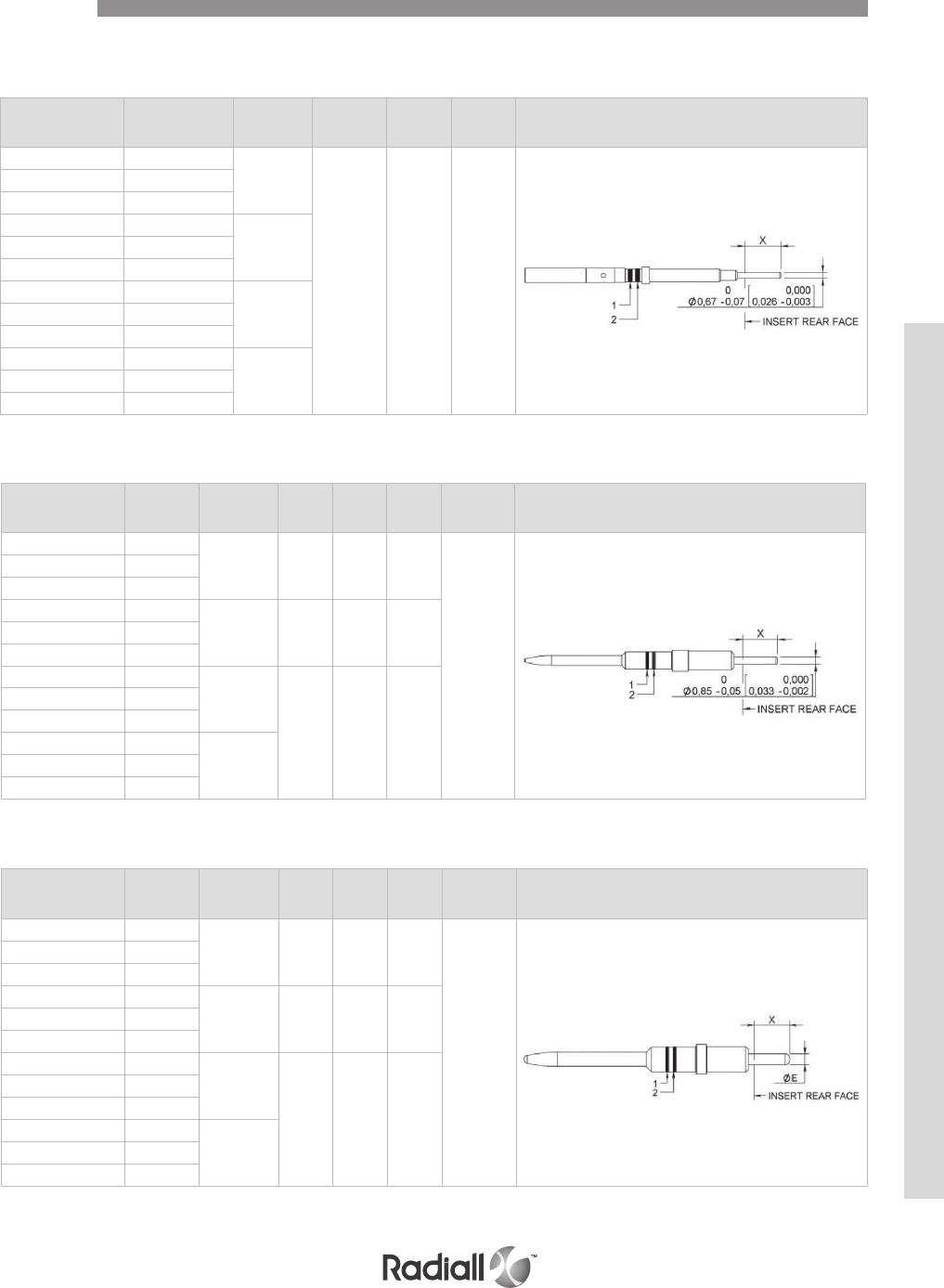
NSX F/G/K – FRONT REMOVABLE PC TAIL
SIZE 22 SOCKET CONTACTS
SIZE 16 PIN CONTACTS
Part number Contact
termination
Dimension X
mm (inch) Ins/Ext Tool Color
band 1
Color
band 2 Figure
620360 YA 4.60/3.80
(.181/.150)
282500 orange green
620360005 ZA
620360500 RA
620361 Y7.20/6.40
(.283/.252)
620361005 Z
620361500 R
620362 YB 10.30/9.50
(.406/.374)
620362005 ZB
620362500 RB
620363 YC 13.60/12.80
(.535/.504)
620363005 ZC
620363500 RC
Part number Contact
termination
Dimension X
mm (inch)
Ins/Ext
Tool
Color
band 1
Color
band 2
E dia
mm (inch) Figure
620234018 YA 4.60/3.80
(.181/.150) 282504 orange blue
1.32/1.22
(.052/.048)
620234019 ZA
620234518 RA
620234004 Y7.20/6.40
(.283/.252) 282504 orange blue620234017 Z
620234504 R
620234003 YB 10.30/9.50
(.406/.374)
282504 orange blue
620234008 ZB
620234503 RB
620234021 YC 13.60/12.80
(.535/.504)
620234022 ZC
620234521 RC
SIZE 20 PIN CONTACTS
Part number Contact
termination
Dimension X
mm (inch)
Ins/Ext
Tool
Color
band 1
Color
band 2
E dia
mm (inch) Figure
620214018 YA 4.60/3.80
(.181/.150) 282503 orange red
0.85/0.80
(.033/.031)
620214019 ZA
620214518 RA
620214010 Y7.20/6.40
(.283/.252) 282503 orange red620214013 Z
620214510 R
620214003 YB 10.30/9.50
(.406/.374)
282503 orange red
620214008 ZB
620214503 RB
620214021 YC 13.60/12.80
(.535/.504)
620214022 ZC
620214521 RC
Contacts
NSX SERIES
4-59
Our Most Important Connection is with You.™
Go online for data sheets & assembly instructions. Visit www.radiall.com and enter the part number.
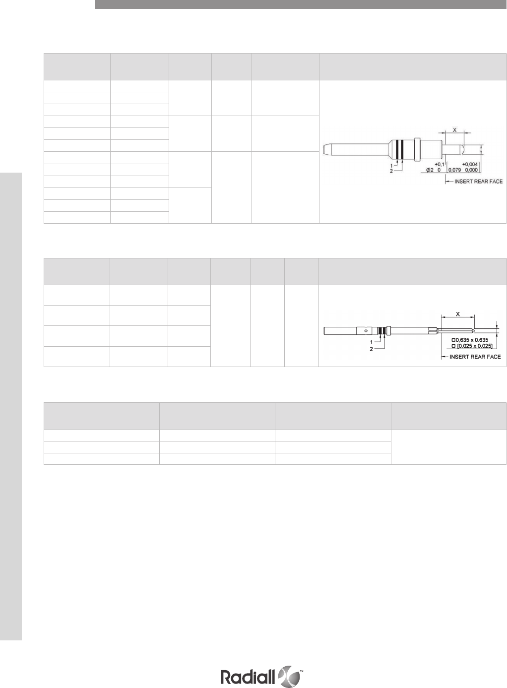
NSX F/G/K – FRONT REMOVABLE PC TAIL
SIZE 12 PIN CONTACTS
Part number Contact
termination
Dimension X
mm (inch) Ins/Ext Tool Color
band 1
Color
band 2 Figure
620244018 YA 4.60/3.80
(.181/.150) 282549005 orange yellow
620244019 ZA
620244518 RA
620244005 Y7.20/6.40
(.283/.252) 282549005 orange Yellow620244016 Z
620244505 R
620244003 YB 10.30/9.50
(.406/.374)
282549005 orange yellow
620244008 ZB
620244503 RB
620244021 YC 13.60/12.80
(.535/.504)
620244022 ZC
620244521 RC
SIZE 22 SOCKET FRONT REMOVABLE WIRE WRAP CONTACTS
Part number Contact
termination
Dimension X
mm (inch) Ins/Ext Tool Color
band 1
Color
band 2 Figure
620350 K6.9/0.4
(.256/.287)
282500 orange green
620351 V9.9/0.4
(.374/.405)
620352 W13.3/0.4
(.508/.540)
620353 L16.8/0.4
(.645/.677)
SIZE 16 PIN COAX CONTACTS
Part number Contact termination Dimension X
mm (inch) Ins/Ext Tool
618155001 YA 3.8/4.6 (.150/.181)
282504618155002 Y6.4/7.2 (.252/.283)
618155011 YB 9.5/10.3 (.374/.405)
Contacts
NSX SERIES
4-60
Our Most Important Connection is with You.™
Go online for data sheets & assembly instructions. Visit www.radiall.com and enter the part number.
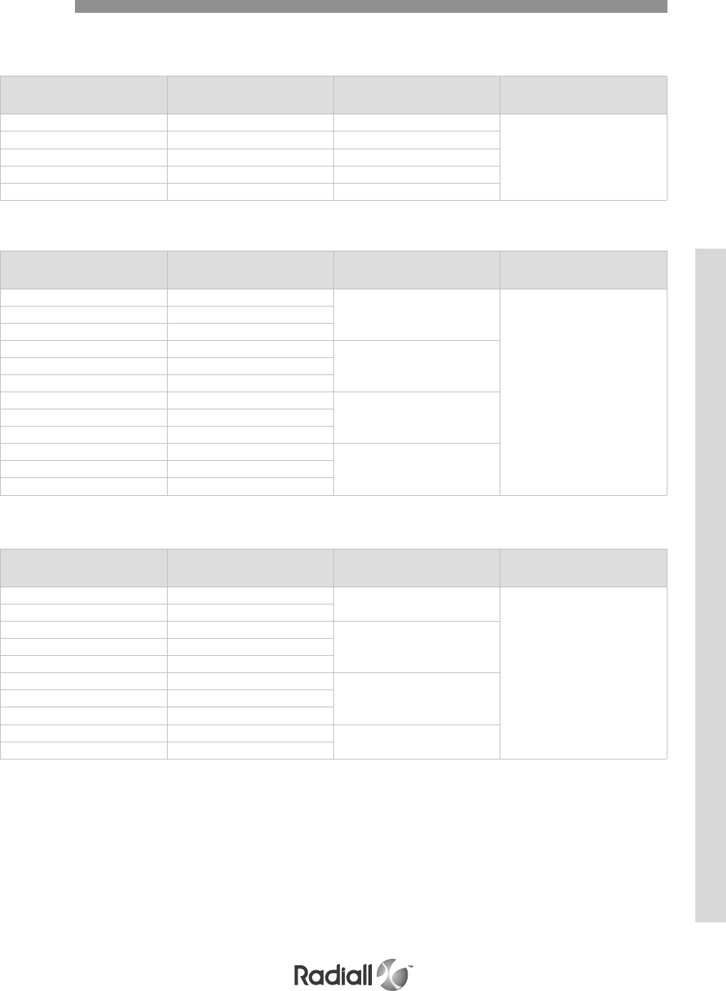
SIZE 5 PIN COAX CONTACTS
Part number Contact termination Dimension X
mm (inch) Ins/Ext Tool
620133009 YA 4.60/3.80
(.181/.150)
282549006
620133509 RA
620133006 Y7.20/6.40
(.283/.252)
620133007 Z
620133506 R
620133003 YB 10.30/9.50
(.406/.374)
620133001 ZB
620133503 RB
620133010 YC 13.60/12.80
(.535/.504)
620133510 RC
SIZE 12 PIN COAX CONTACTS
Part number Contact termination Dimension X
mm (inch) Ins/Ext Tool
618149017 YA 3.8/4.6 (.150/.181)
282549005
618149016 Y6.4/7.2 (.252/.283)
618149018 YB 9.5/10.3 (.374/.405)
618149012 YC 12.8/13.6 (.503/.535)
618149013 ZC 12.8/14.1 (.503/.558)
SIZE 8 PIN COAX CONTACTS
Part number Contact termination Dimension X
mm (inch) Ins/Ext Tool
619140009 YA 12.40/12.20
(.488/.480)
282549009
619140014 ZA
619140509 RA
619140010 Y15.05/14.85
(.592/.584)
619140013 Z
619140510 R
619140007 YB 18.15/17.95
(.715/.706)
619140008 ZB
619140507 RB
619140011 YC 21.45/21.25
(.844/.836)
619140012 ZC
619140511 RC
NSX F/G/K – FRONT REMOVABLE PC TAIL
Contacts
NSX SERIES
4-61
Our Most Important Connection is with You.™
Go online for data sheets & assembly instructions. Visit www.radiall.com and enter the part number.
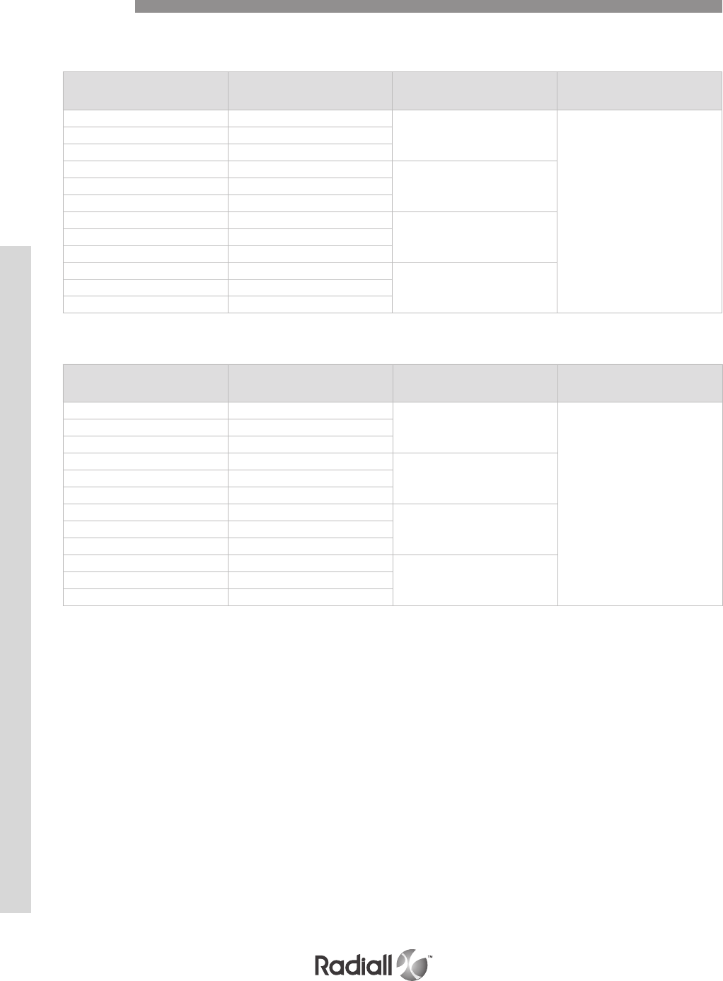
SIZE 8 PIN TRIAX PC TAIL FRONT RELEASE VERSION
SIZE 8 PIN QUADRAX CONTACTS
Part number Contact termination Dimension X
mm (inch) Ins/Ext Tool
619162014 YA 4.60/3.80
(.181/.150)
282549009
619162015 ZA
619162514 RA
619162011 Y7.20/6.40
(.283/.252)
619162012 Z
619162511 R
619162016 YB 10.30/9.50
(.406/.374)
619162017 ZB
619162516 RB
619162009 YC 13.60/12.80
(.535/.504)
619162010 ZC
619162509 RC
Part number Contact termination Dimension X
mm (inch) Ins/Ext Tool
620176009 YA 4.60/3.80
(.181/.150)
282549009
620176016 ZA
620176509 RA
620176008 Y7.20/6.40
(.283/.252)
620176010 Z
620176508 R
620176011 YB 10.30/9.50
(.406/.374)
620176012 ZB
620176511 RB
620176013 YC 13.60/12.80
(.535/.504)
620176014 ZC
620176513 RC
NSX F/G/K – FRONT REMOVABLE PC TAIL
Contacts
NSX SERIES
4-62
Our Most Important Connection is with You.™
Go online for data sheets & assembly instructions. Visit www.radiall.com and enter the part number.
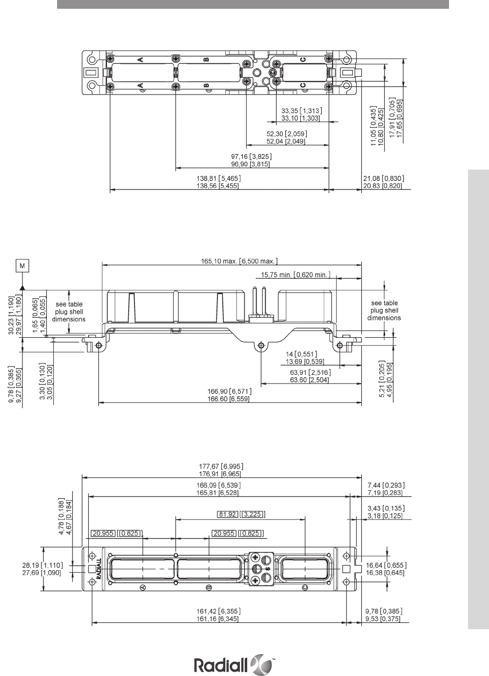
NON ENVIRONMENTAL SIZE 1 PLUG SHELL DIMENSIONS
FRONT VIEW
SIDE VIEW
REAR VIEW
Dimensions
NSX SERIES
4-63
Our Most Important Connection is with You.™
Go online for data sheets & assembly instructions. Visit www.radiall.com and enter the part number.
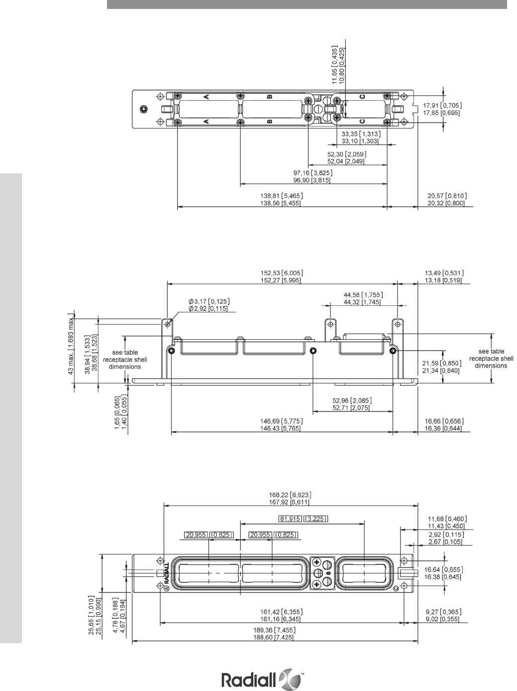
NON ENVIRONMENTAL SIZE 1 RECEPTACLE SHELL DIMENSIONS
REAR VIEW
SIDE VIEW
FRONT VIEW
Dimensions
NSX SERIES
4-64
Our Most Important Connection is with You.™
Go online for data sheets & assembly instructions. Visit www.radiall.com and enter the part number.
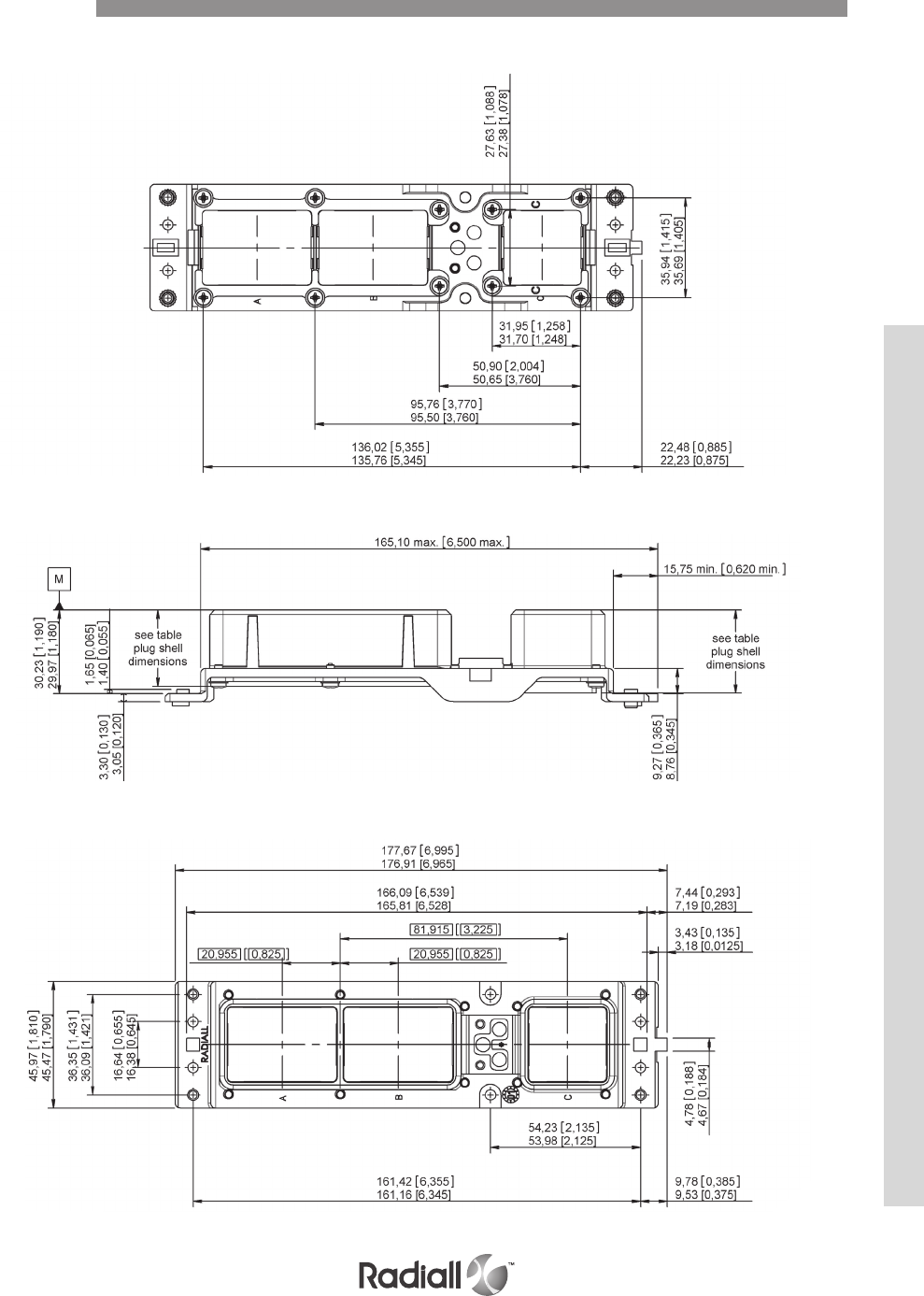
NON ENVIRONMENTAL SIZE 2 PLUG SHELL DIMENSIONS
FRONT VIEW
SIDE VIEW
REAR VIEW
Dimensions
NSX SERIES
4-65
Our Most Important Connection is with You.™
Go online for data sheets & assembly instructions. Visit www.radiall.com and enter the part number.
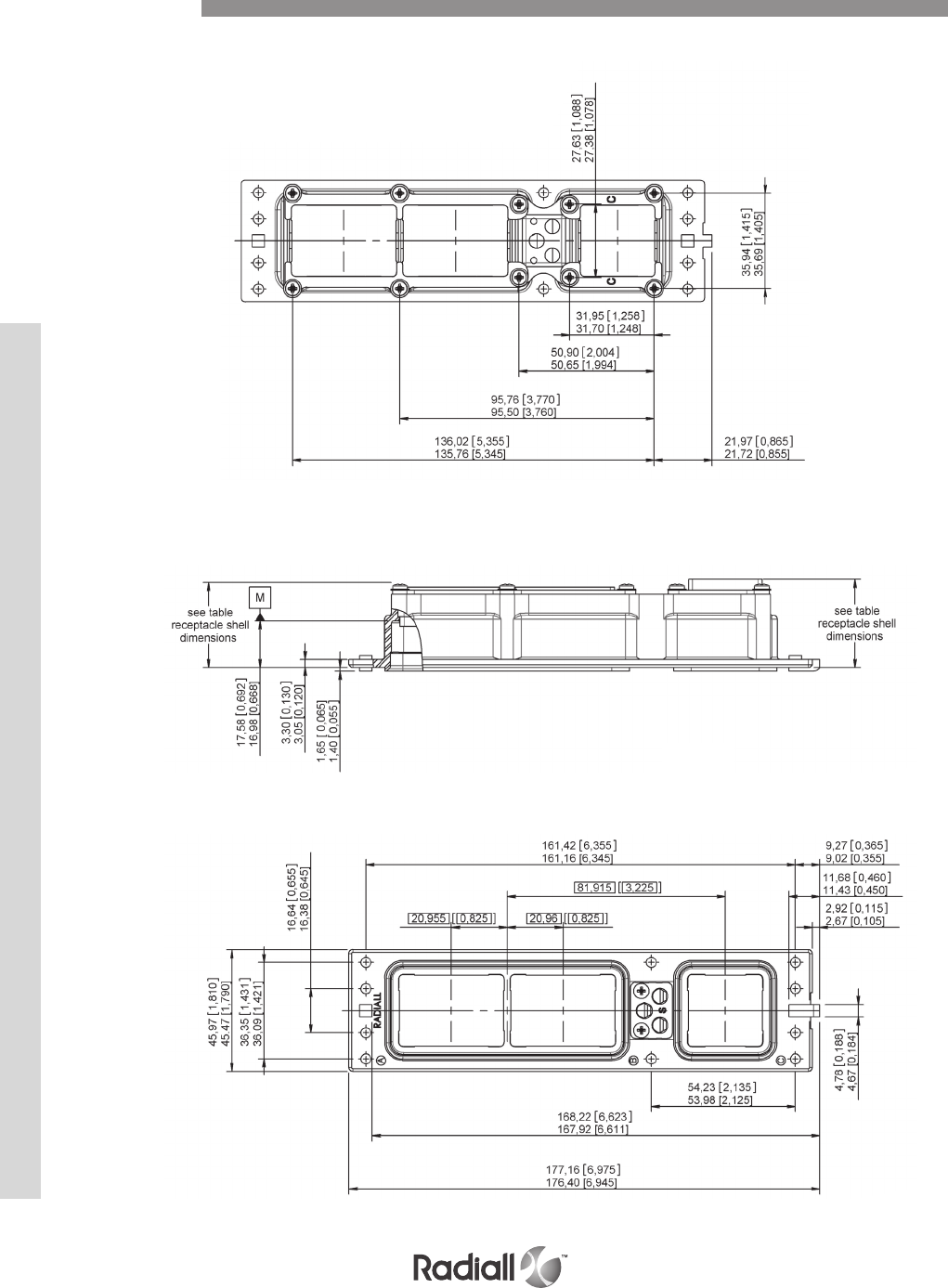
NON ENVIRONMENTAL SIZE 2 RECEPTACLE SHELL DIMENSIONS
FRONT VIEW
REAR VIEW
Dimensions
SIDE VIEW
NSX SERIES
4-66
Our Most Important Connection is with You.™
Go online for data sheets & assembly instructions. Visit www.radiall.com and enter the part number.
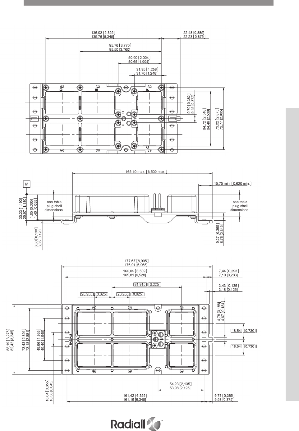
NON ENVIRONMENTAL SIZE 3 PLUG SHELL DIMENSIONS
FRONT VIEW
SIDE VIEW
REAR VIEW
Dimensions
NSX SERIES
4-67
Our Most Important Connection is with You.™
Go online for data sheets & assembly instructions. Visit www.radiall.com and enter the part number.
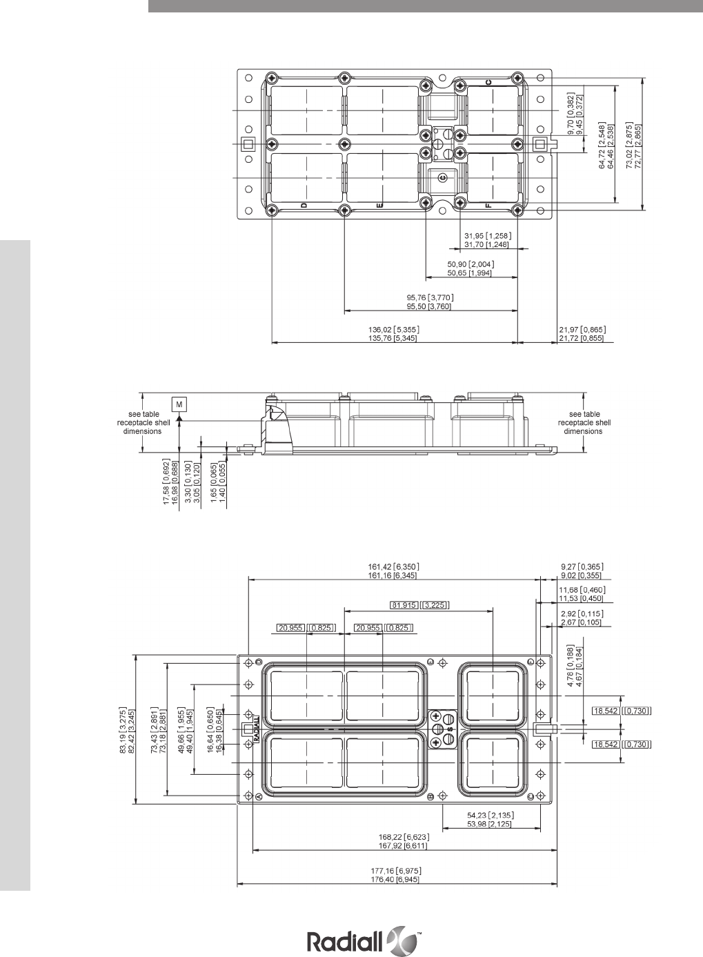
NON ENVIRONMENTAL SIZE 3 RECEPTACLE SHELL DIMENSIONS
FRONT VIEW
SIDE VIEW
REAR VIEW
Dimensions
NSX SERIES
4-68
Our Most Important Connection is with You.™
Go online for data sheets & assembly instructions. Visit www.radiall.com and enter the part number.

ENVIRONMENTAL SIZE 1 PLUG AND RECEPTACLE DIMENSIONS
RECEPTACLE SHELL
PLUG SHELL
Dimensions
NSX SERIES
4-69
Our Most Important Connection is with You.™
Go online for data sheets & assembly instructions. Visit www.radiall.com and enter the part number.

ENVIRONMENTAL SIZE 2 & 3 PLUG AND RECEPTACLE DIMENSIONS
RECEPTACLE SHELL
PLUG SHELL
Dimensions
NSX SERIES
4-70
Our Most Important Connection is with You.™
Go online for data sheets & assembly instructions. Visit www.radiall.com and enter the part number.
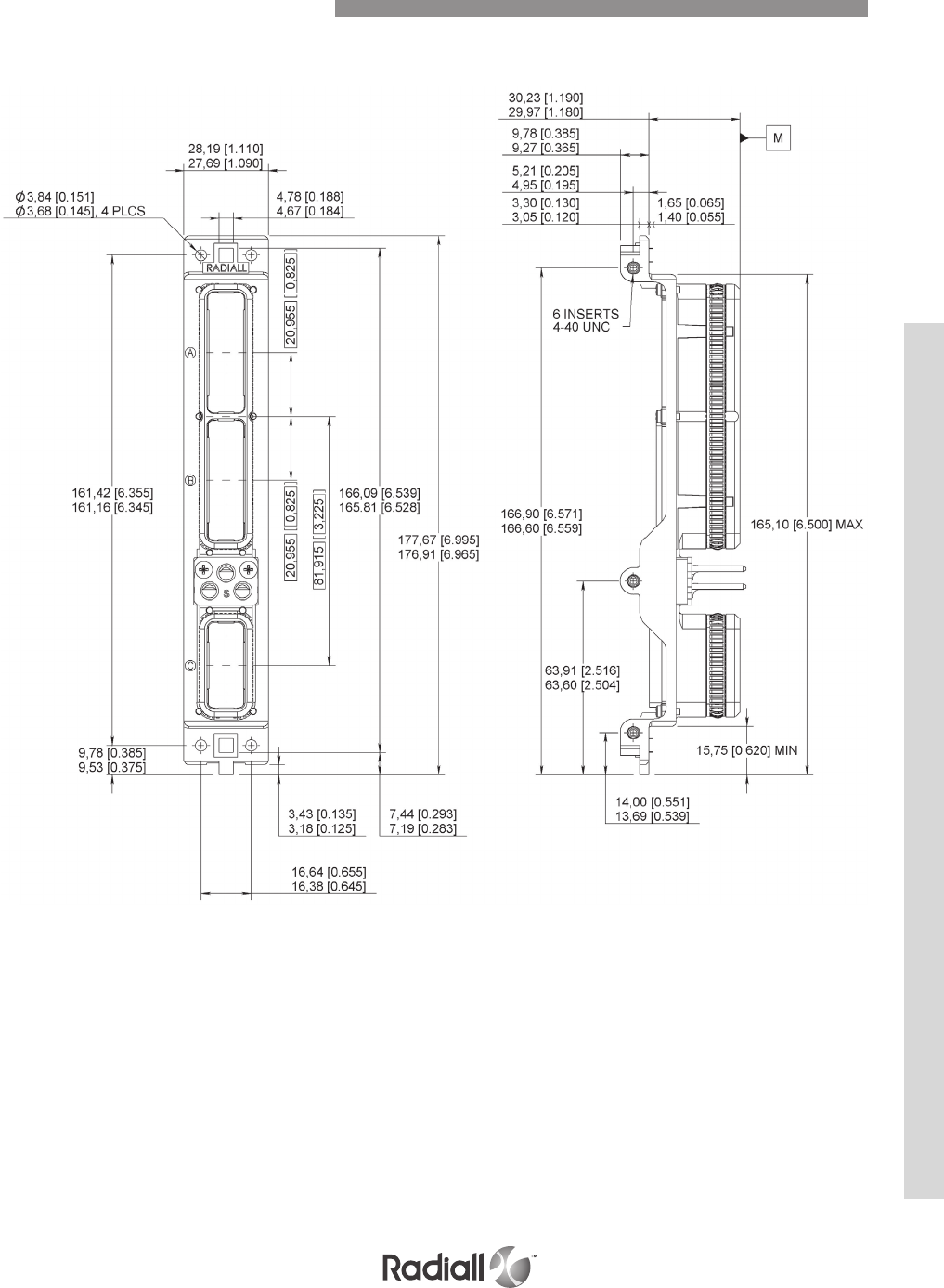
HOW TO ORDER
See page 4-11
EMI/RFI NSX Size 1 Plug Dimensions
NSX SERIES
4-71
Our Most Important Connection is with You.™
Go online for data sheets & assembly instructions. Visit www.radiall.com and enter the part number.
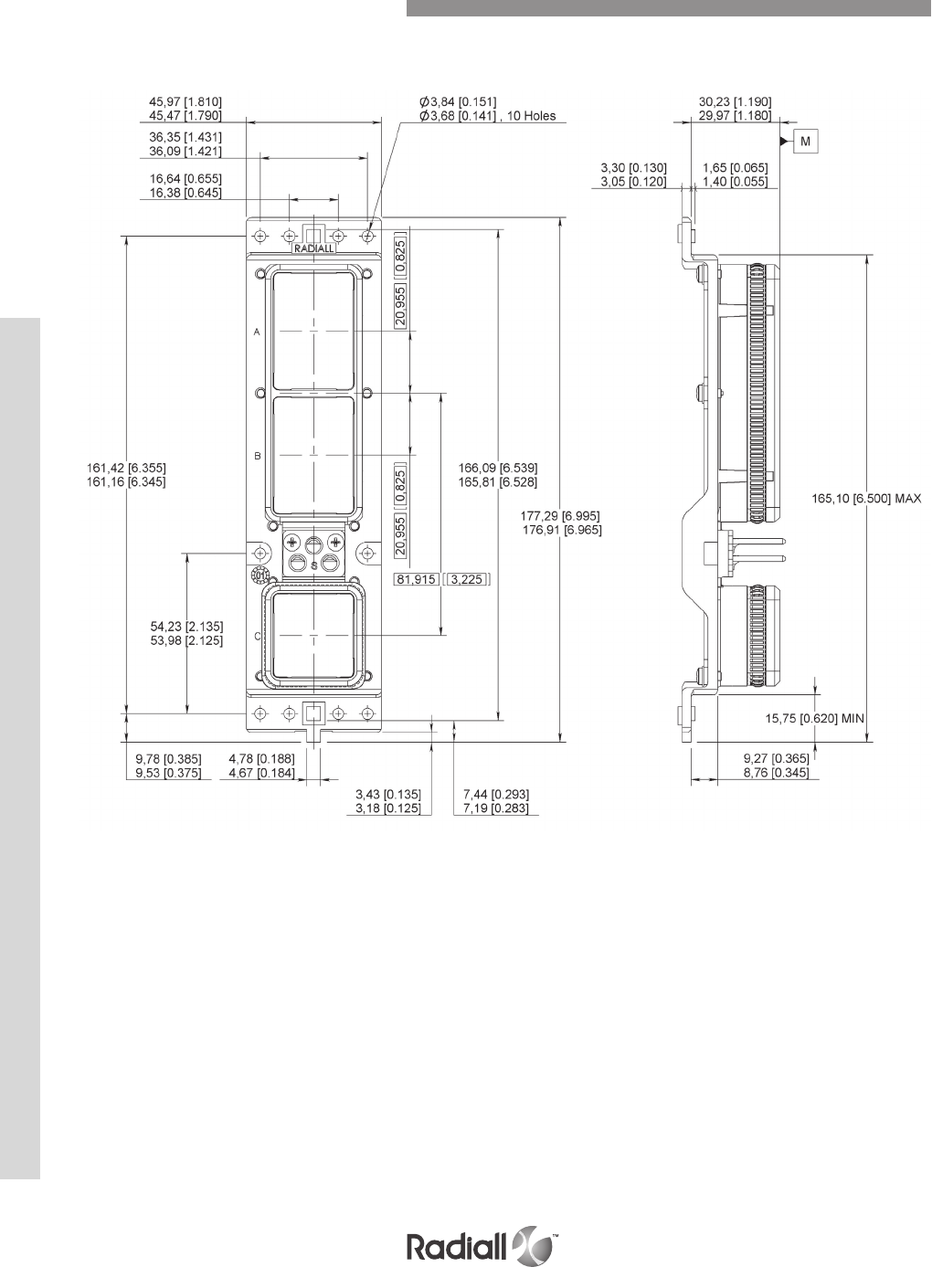
HOW TO ORDER
See page 4-11
EMI/RFI NSX Size 2 Plug Dimensions
NSX SERIES
4-72
Our Most Important Connection is with You.™
Go online for data sheets & assembly instructions. Visit www.radiall.com and enter the part number.
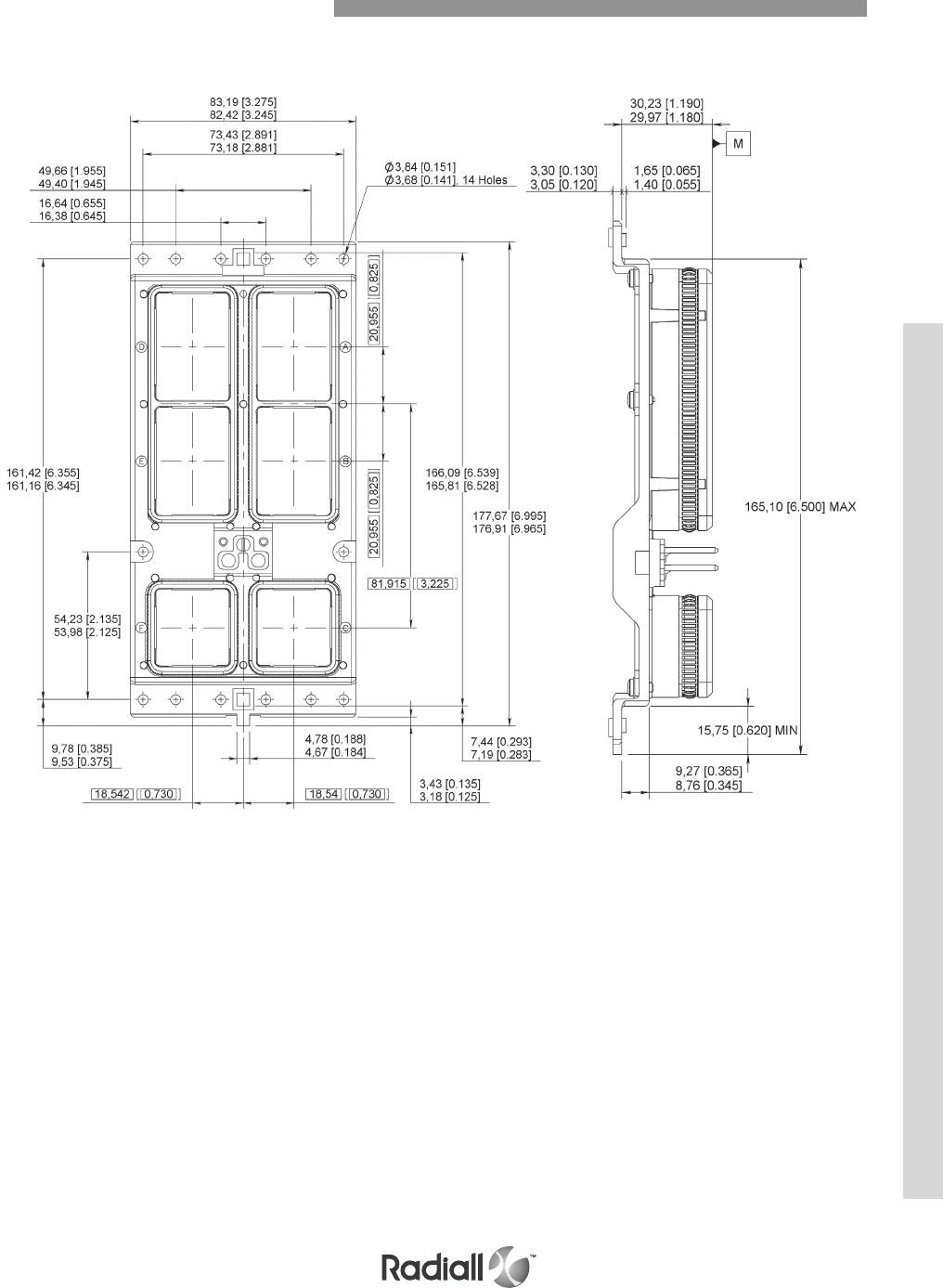
HOW TO ORDER
See page 4-11
EMI/RFI NSX Size 3 Plug Dimensions
NSX SERIES
4-73
Our Most Important Connection is with You.™
Go online for data sheets & assembly instructions. Visit www.radiall.com and enter the part number.
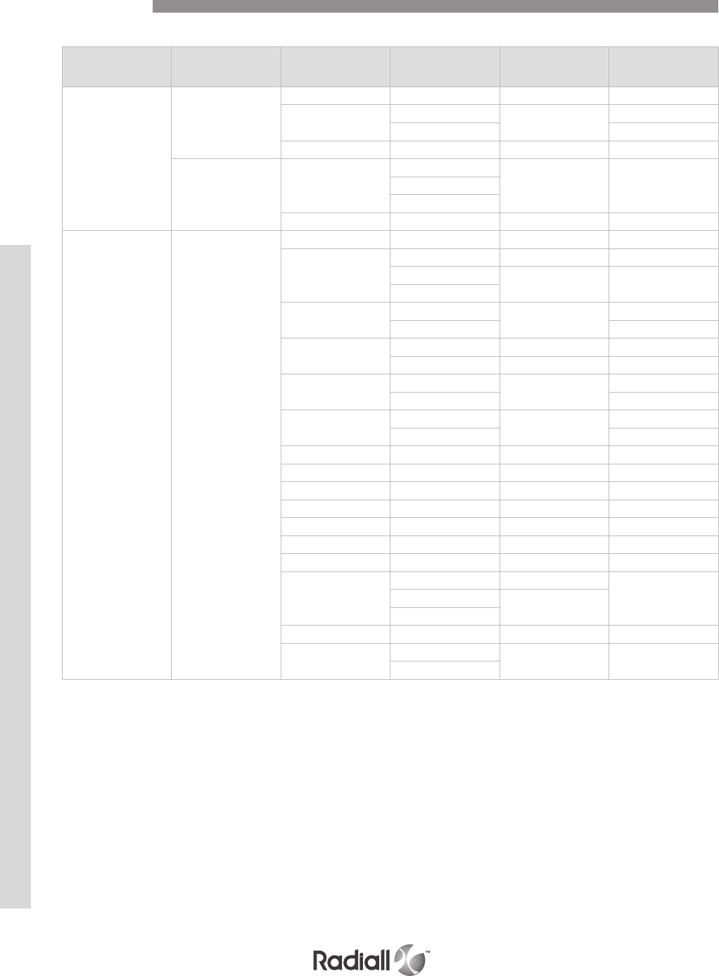
PLUG SHELL DIMENSIONS
Shell size Cavity Contact arrangement Contact size Class N
mm (inch) max
Classe E,H,C
mm (inch) max
1
A, B
60 22 28 (1.102) 35.5 (1.398)
30T2 22 28 (1.102) 35.5 (1.398)
836.8 (1.449)
4C 530.5 (1.200) -
C5C2
16
30.5 (1.200) 39.3 (1.547)12
5
40 22 28 (1.102) 35.5 (1.398)
2, 3 A, B, D, E
150 22 28 (1.102) 35.5 (1.398)
121
22 28 (1.102) 35.5 (1.398)
20 30.5 (1.200) 39.3 (1.547)
16
120T2 22 28 (1.102) 35.5 (1.398)
836.8 (1.449)
118Q2 22 28 (1.102) 35.5 (1.398)
828 (1.102) 36.8 (1.449)
71C1 22 28 (1.102) 35.5 (1.398)
1 -
1C71 22 28 (1.102) 35.5 (1.398)
1 -
60 20 30.5 (1.200) 39.3 (1.547)
24 12 30.5 (1.200) 39.3 (1.547)
10T10 830.5 (1.200) 39.3 (1.547)
Q11 830.5 (1.200) 39.3 (1.547)
C2 128 (1.102) -
C4 128 (1.102) -
35 16 30.5 (1.200) 39.3 (1.547)
110
22 28 (1.102)
-20 30.5 (1.200)
12
36F36 16 LuxCis® 30.5 (1.200) 39 (1.535)
20F12Q8 830.5 (1.200) 39 (1.535)
16 LuxCis®
Dimensions
NSX SERIES
4-74
Our Most Important Connection is with You.™
Go online for data sheets & assembly instructions. Visit www.radiall.com and enter the part number.

PLUG SHELL DIMENSIONS
Shell size Cavity Contact arrangement Contact size Class N
mm (inch) max
Classe E,H,C
mm (inch) max
2, 3 C, F
100 22 28 (1.102) 35.5 (1.398)
85
22
28 (1.102)
35.5 (1.398)
20 39.3 (1.547)
16
34 20 30.5 (1.200) 39.3 (1.547)
16
20T4 20 30.5 (1.200) 39.3 (1.547)
8
20Q4 20 30.5 (1.200) 39.3 (1.547)
8
13C2
20
30.5 (1.200) 39.3 (1.547)
16
12
5
6T6 830.5 (1.200) 39.3 (1.547)
Q6 830.5 (1.200) 39.3 (1.547)
62Q2
22
28 (1.102) 36.8 (1.449)16
8
68Q2 22 28 (1.102) 35.5 (1.398)
836.8 (1.449)
11Q2
20
30.5 (1.200) 39.3 (1.547)
16
12
8
11WQ2
20
30.5 (1.200) 39.3 (1.547)
16
12
8
59
22 28 (1.102) 35.5 (1.398)
16 30.5 (1.200) 39.3 (1.547)
12
12F5C2
16 LuxCis®
30.5 (1.200) 39 (1.535)16
5
17F12Q2
16 LuxCis®
30.5 (1.200) 39 (1.535)
16
12
5
Dimensions
NSX SERIES
4-75
Our Most Important Connection is with You.™
Go online for data sheets & assembly instructions. Visit www.radiall.com and enter the part number.

RECEPTACLE SHELL DIMENSIONS
Shell size Cavity Contact
arrangement Contact size Class N
mm (inch) max
Class E, C
mm (inch) max
Class F
mm (inch) max
Classe G
mm (inch) max
1
A, B
60 22 31 (1.220) 38.9 (1.531) 30.93/29.84
(1.218/1.175) -
30T2 22 31 (1.220) 38.9 (1.531) 30.93/29.84
(1.218/1.175)
30.93/29.84
(1.218/1.175)
840.5 (1.594)
4C 533.45 (1.317) - - 30.93/29.84
(1.218/1.175)
C
5C2
16
33.45 (1.317 43 (1.693) -30.93/29.84
(1.218/1.175)
12
5
40 22 31 (1.220) 38.9 (1.531) 30.93/29.84
(1.218/1.175) -
412 33.45 (1.317) 43 (1.693) - -
2, 3 A, B, D, E
150 22 31 (1.220) 38.9 (1.531) 30.93/29.84
(1.218/1.175) -
121
22 31 (1.220) 38.9 (1.531) 30.93/29.84
(1.218/1.175) 30.93/29.84
(1.218/1.175)
20 33.45 (1.317) 43 (1.693) 33.45
(1.317)
16
120T2
22 31 (1.220) 38.9 (1.531) 30.93/29.84
(1.218/1.175) -
831 (1.220) 40.5 (1.594) 30.93/29.84
(1.218/1.175) -
118Q2
22 31 (1.220) 38.9 (1.531) 30.93/29.84
(1.218/1.175) -
831 (1.220) 40.5 (1.594) 30.93/29.84
(1.218/1.175) -
71C1 22 31 (1.220) 38.9 (1.531) 30.93/29.84
(1.218/1.175) -
1 -
1C71 22 31 (1.220) 38.9 (1.531) 30.93/29.84
(1.218/1.175) -
1 -
60 20 33.45 (1.317) 43 (1.693) -30.93/29.84
(1.218/1.175)
24 12 33.45 (1.317) 43 (1.693) -30.93/29.84
(1.218/1.175)
10T10 833.45 (1.317) 43 (1.693) -30.93/29.84
(1.218/1.175)
Q11 833.45 (1.317) 43 (1.693) -30.93/29.84
(1.218/1.175)
C2 131 (1.220) ---
C4 131 (1.220) ---
35 16 33.45 (1.317) 43 (1.693) -30.93/29.84
(1.218/1.175)
110
22 31 (1.220) 38.9 (1.531) 30.93/29.84
(1.218/1.175) 30.93/29.84
(1.218/1.175)
20 33.45 (1.317) 43 (1.693) 33.45
(1.317)
12
Dimensions
NSX SERIES
4-76
Our Most Important Connection is with You.™
Go online for data sheets & assembly instructions. Visit www.radiall.com and enter the part number.
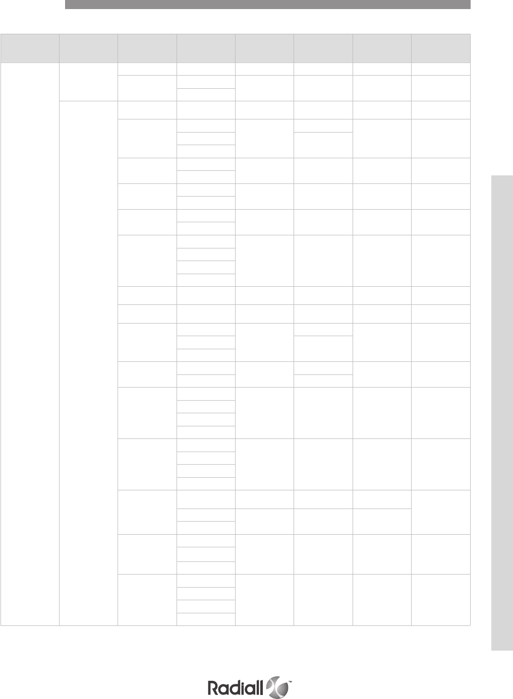
RECEPTACLE SHELL DIMENSIONS
Shell size Cavity Contact
arrangement Contact size Class N
mm (inch) max
Class E, C
mm (inch) max
Class F
mm (inch) max
Classe G
mm (inch) max
2, 3
A, B, D, E
36F36 16 LuxCis® 35.5 (1.398) 44 (1.732) - -
20F12Q8 16 LuxCis® 35.5 (1.398) 44 (1.732) -30.93/29.84
(1.218/1.175)
8
C, F
100 22 31 (1.220) 38.9 (1.531) 30.93/29.84
(1.218/1.175) -
85
22
31 (1.220)
38.9 (1.531)
30.93/29.84
(1.218/1.175)
30.93/29.84
(1.218/1.175)
20 40.5 (1.595)
16
34 20 33.45 (1.317) 43 (1.693) -30.93/29.84
(1.218/1.175)
16
20T4 20 33.45 (1.317) 43 (1.693) -30.93/29.84
(1.218/1.175)
8
20Q4 20 33.45 (1.317) 43 (1.693) -30.93/29.84
(1.218/1.175)
8
13C2
20
33.45 (1.317) 43 (1.693) -30.93/29.84
(1.218/1.175)
16
12
5
6T6 833.45 (1.317) 43 (1.693) -30.93/29.84
(1.218/1.175)
Q6 833.45 (1.317) 43 (1.693) -30.93/29.84
(1.218/1.175)
62Q2
22
31 (1.220)
38.9 (1.531)
30.93/29.84
(1.218/1.175)
30.93/29.84
(1.218/1.175)
16 40.5 (1.595)
8
68Q2 22 31 (1.220) 38.9 (1.531) 30.93/29.84
(1.218/1.175)
30.93/29.84
(1.218/1.175)
840.5 (1.595)
11Q2
20
33.45 (1.317) 43 (1.693) -30.93/29.84
(1.218/1.175)
16
12
8
11WQ2
20
33.45 (1.317) 43 (1.693) -30.93/29.84
(1.218/1.175)
16
12
8
59
22 31 (1.220) 38.9 (1.531) 30.93/29.84
(1.218/1.175) 30.93/29.84
(1.218/1.175)
16 33.45 (1.317) 43 (1.693) 33.45 (1.317)
12
12F5C2
16 LuxCis®
35.5 (1.398) 44 (1.732) - -16
5
17F12Q2
16 LuxCis®
35.5 (1.398) 44 (1.732) -30.93/29.84
(1.218/1.175)
16
12
5
CLASS F: size 22 contacts are front release, front removable. Other sizes are rear release, rear removable
CLASS G: all contacts are front release, front removable
Dimensions
NSX SERIES
4-77
Our Most Important Connection is with You.™
Go online for data sheets & assembly instructions. Visit www.radiall.com and enter the part number.
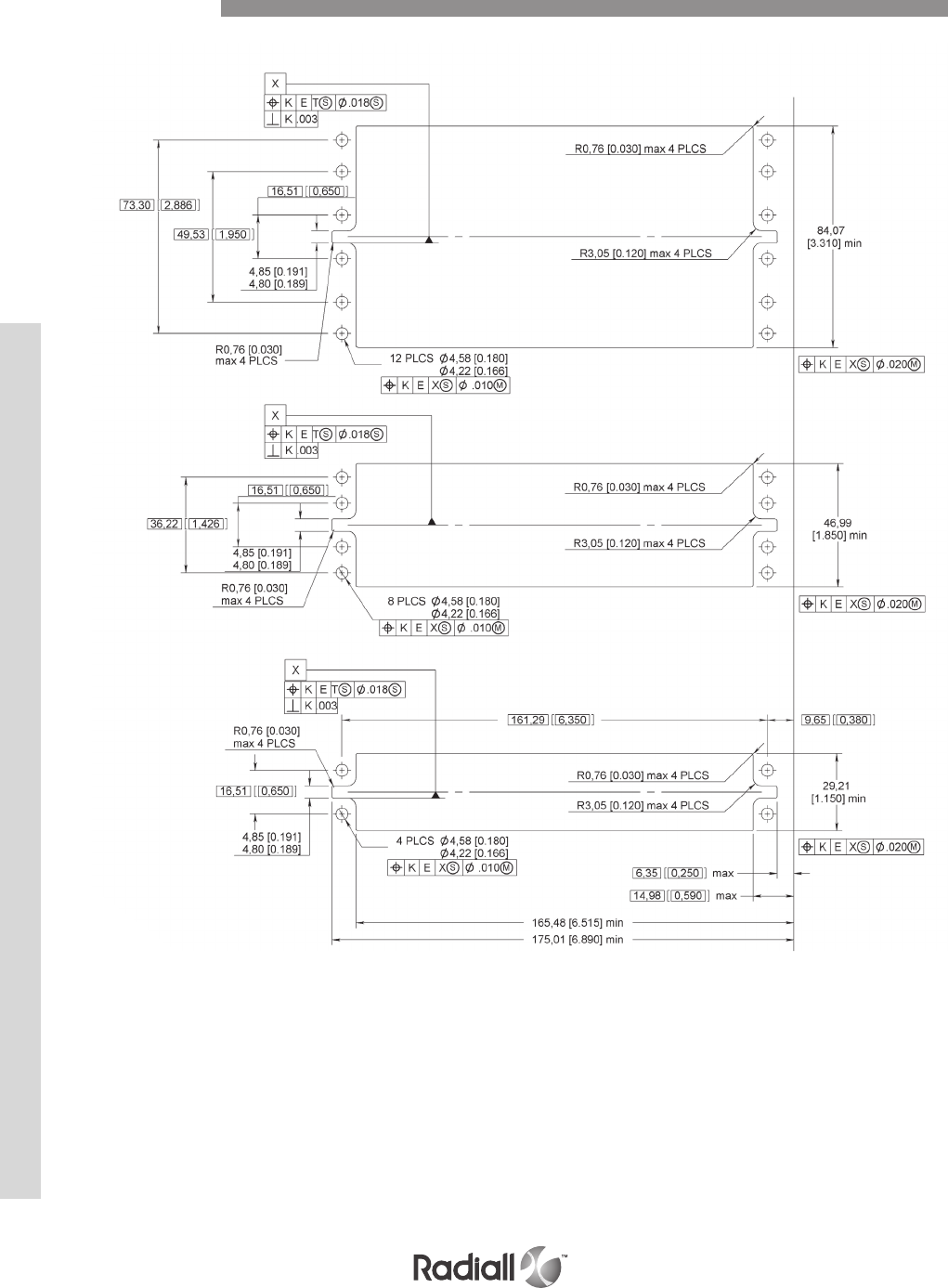
PANEL CUT OUT FOR PLUG SIZE 1, 2 AND 3
SIZE 3
SIZE 2
SIZE 1
Panel Cut Out
NSX SERIES
4-78
Our Most Important Connection is with You.™
Go online for data sheets & assembly instructions. Visit www.radiall.com and enter the part number.
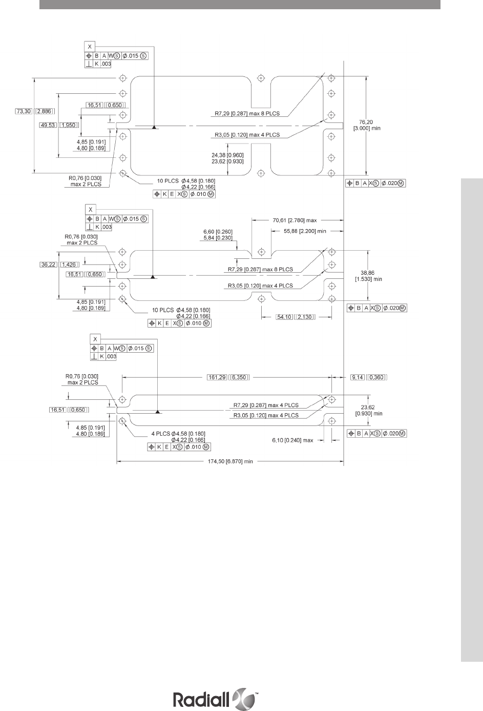
PANEL CUT OUT FOR RECEPTACLE SIZE 1, 2 AND 3
SIZE 3
SIZE 2
SIZE 1
Panel Cut Out
NSX SERIES
4-79
Our Most Important Connection is with You.™
Go online for data sheets & assembly instructions. Visit www.radiall.com and enter the part number.
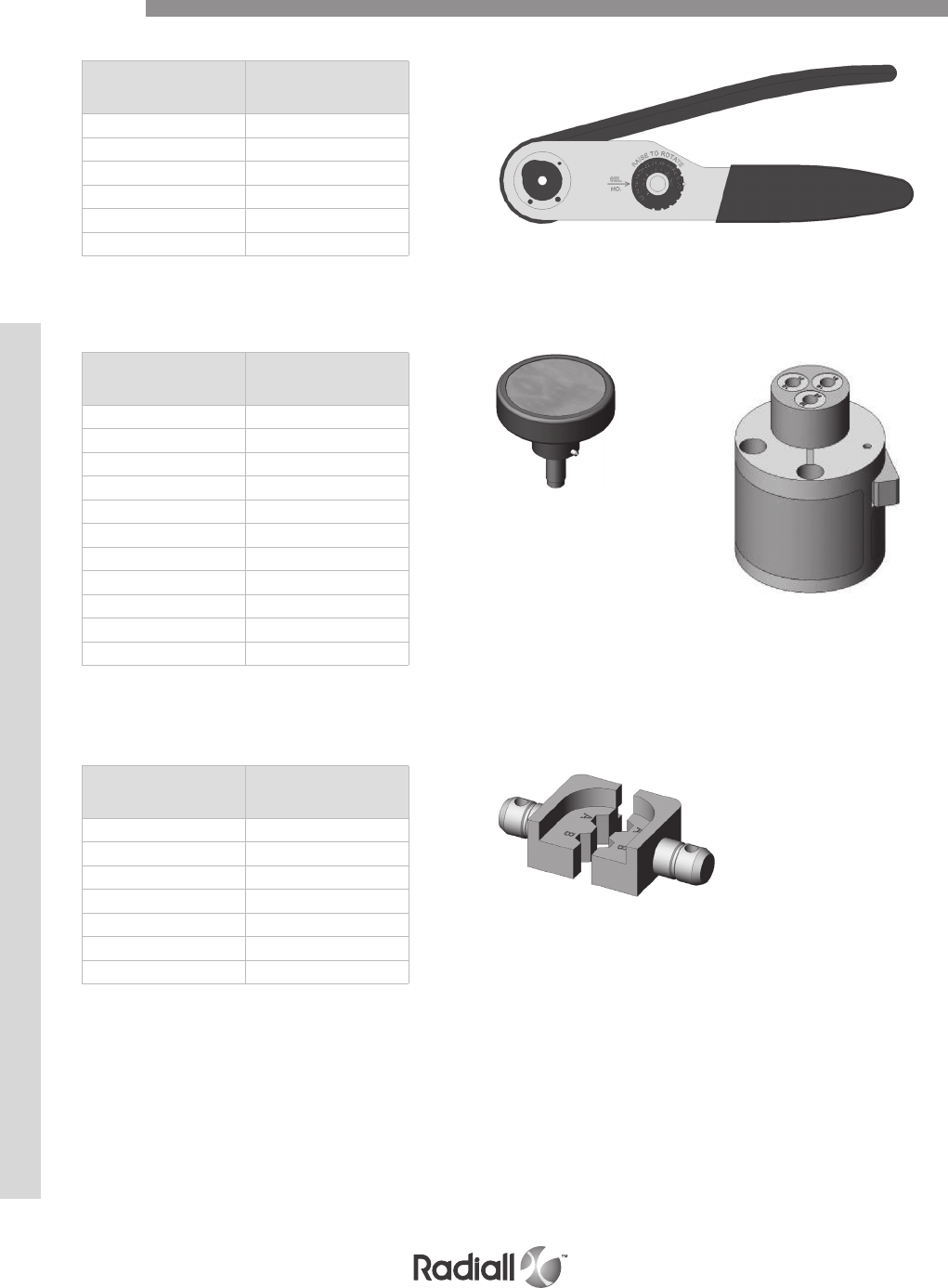
Part number Crimping tools
282291 M22520/1.01
282281 M22520/2.01
282292 M22520/4.01
282293 M22520/5.01
/M22520/23.01
/M22520/31.01
CRIMPING TOOLS
Part number Mil spec P/N
282972 M22520/1.02
282579 M22520/1.11
282997 M22520/1.13
282971 M22520/2.08
282970 M22520/2.23
/M22520/23.09
282550 (DANIELS K345) /
282555 (DANIELS K370) /
282556 /
282587 /
282588 /
POSITIONERS
Part number Mil spec P/N
282246 M22520/5.05
/M22520/5.13
/M22520/5.29
282236 M22520/5.45
282247 M22520/5.61
/M22520/23.02
/M22520/5.104
DIES
Tools
NSX SERIES
4-80
Our Most Important Connection is with You.™
Go online for data sheets & assembly instructions. Visit www.radiall.com and enter the part number.

Part number Mil spec P/N Description
282885 M81969/1.01 ins/ext tool for rear release rear removable size 22 contacts (crimp version)
282886 M81969/1.02 ins/ext tool for rear release rear removable size 20 contacts (crimp version)
282546 M81969/1.03 ins/ext tool for rear release rear removable size 16 contacts (crimp version)
282946 M81969/28.01 ins/ext tool for rear release rear removable size 5 coaxial contacts (metallic)
282500 /ins/ext tool for front release front removable size 22 contacts
282503 /ins/ext tool for front release front removable size 20 contacts
282504 /ins/ext tool for front release front removable size 16 contacts
282549005 /ins/ext tool for front release front removable size 12 contacts
282890 /ins/ext tool for rear release size 22 contacts solder tail and wire wrap terminations
282549011 /insertion tool for front release front removable size 8 triaxial contacts, solder tail version
282549004 M81969/14.04 extraction tool for rear release rear removable size 12 contacts
/M81969/19.02 extraction tool for front release rear removable size 12 power contacts
/M81969/19.03 extraction tool for front release rear removable size 8 contacts
282549001 M81969/28.03 extraction tool for rear release rear removable size 8 contacts
282549004 /extraction tool for rear release rear removable size 12 contacts (crimp version)
282548 /extraction tool for rear release rear removable size 5 coaxial contacts
282549009 /extraction tool for front release front removable size 8 triaxial contacts
282549012 /extraction tool for front release rear removable size 8 triaxial contacts
282892 /extraction tool for rear release rear removable size 16 coaxial contacts
282945 /extraction tool for rear release rear removable size 12 coaxial contacts
282548 /extraction tool for rear release rear removable size 5 coaxial contacts (plastic)
INSERTION/EXTRACTION TOOLS
Tools
NSX SERIES
4-81
Our Most Important Connection is with You.™
Go online for data sheets & assembly instructions. Visit www.radiall.com and enter the part number.
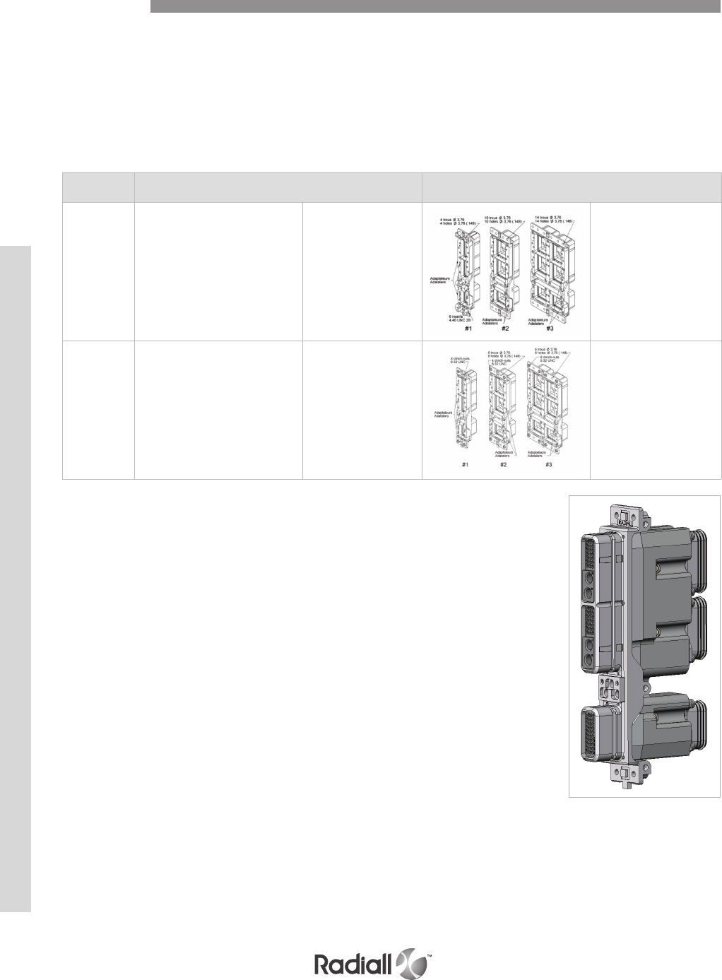
EMI BACKSHELLS
Radiall is proud to introduce two ways to integrate EMI backshells on Arinc 600 connectors:
- Backshell adapters plates
- Radiall backshell solution
Backshell adapters plates:
Backshell adapters plates can be delivered with NSX connectors when choosing modification code 60 and 61.
Accessories
Radiall backshell solution
- High EMI performances
- Easy installation and maintenance with:
Modular backshells (1 or 2 pieces backshells)
Captive screws
- Available on size 1, 2 and 3 Arinc 600 connectors
- Round or oblong chimneys
Please, contact Radiall for more information about NSX backshells
Combination
Code Receptacle shell Plug shell
60
(1) -- --
Shell size 1: Qty = 4 holes
Ø3.76 (.148) & Qty = 6 4-40
UNC 2B
Shell size 2: Qty = 10 holes
Ø3.76 (.148)
Shell size 3: Qty = 14 holes
Ø3.76 (.148)
delivered with backshell
adapters plates
61
(1) -- --
Shell size 1: Qty = 4 6-32 UNC
Shell size 2: Qty = 6 holes
Ø3.76 (.148) & Qty = 4 6-32
UNC
Shell size 3: Qty = 6 holes
Ø3.76 (.148) & Qty = 8 6-32
UNC
delivered with backshell
adapters plates
NSX SERIES
4-82
Our Most Important Connection is with You.™
Go online for data sheets & assembly instructions. Visit www.radiall.com and enter the part number.
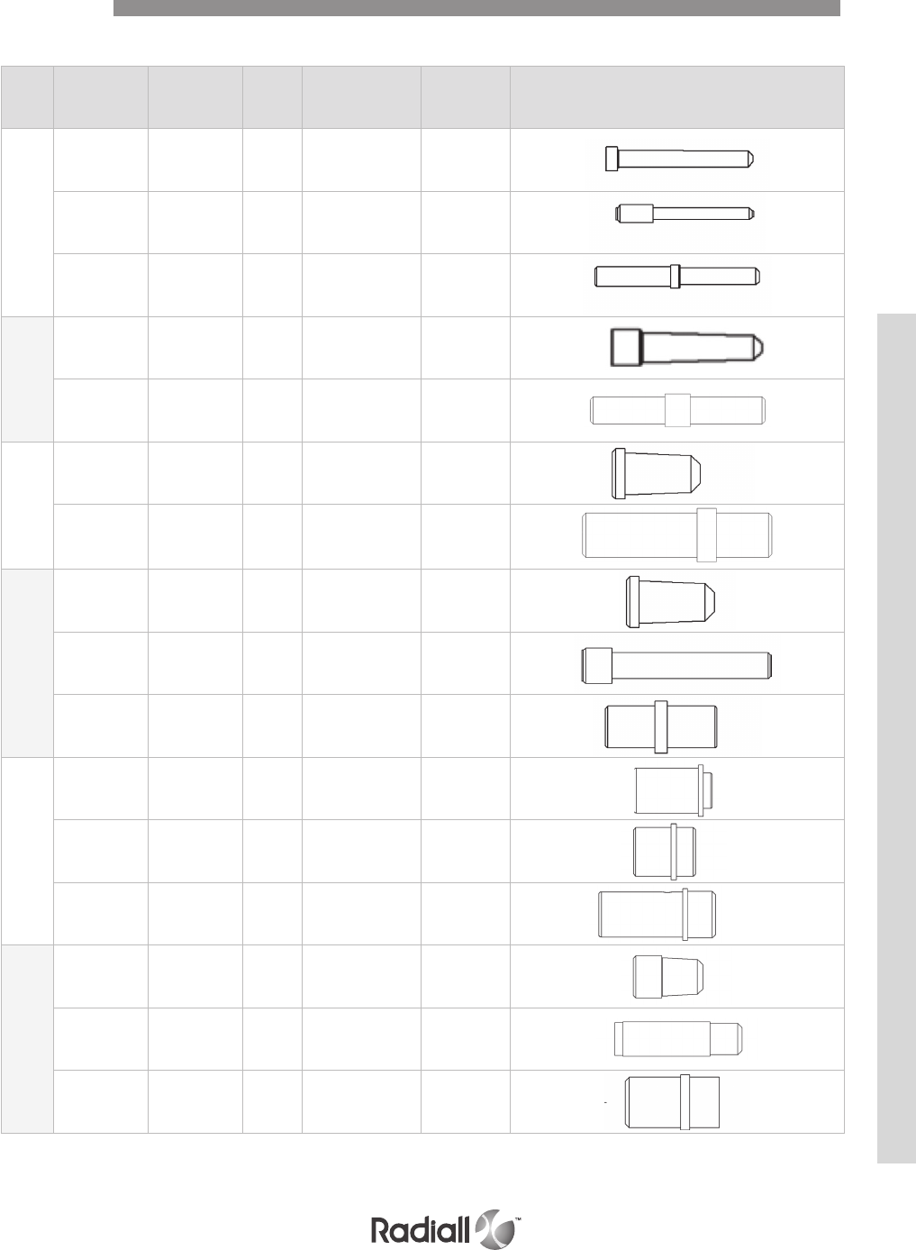
FILLER PLUGS (Non environmental)
Accessories
Size Contact cavity
version Ins Ext Color/Type Part Number Drawing
22
for pin
& socket rear rear black 620920
for socket front front aluminium 620919
for socket front front white 620926
20
for pin
& socket rear rear red 620921
for pin
& socket front front white 620934001
16
for pin
& socket rear rear blue 620922
for pin
& socket front front white 620935001
12
for pin
& socket rear rear yellow 620923
for pin front front white 620936001
for pin front front nickel 620936002
8
for pin rear rear nickel 619953
for pin front front nickel 619552
for socket rear rear nickel 619950
5
for pin rear rear white 620924
for socket rear rear white 620925
for pin
& socket front front white 620937001
NSX SERIES
4-83
Our Most Important Connection is with You.™
Go online for data sheets & assembly instructions. Visit www.radiall.com and enter the part number.

SEALING PLUGS (Environmental)
Sealing plugs are dedicated to environmental inserts.
The arrow shows the direction which you have to insert the plug
Accessories
Size Contact cavity
version Ins Ext Color/Type Part Number Drawing
22 for pin & socket rear rear black 616910
20 for pin & socket rear rear red 616911
16 for pin & socket rear rear green 616912
12 for pin & socket rear rear orange 616913
8 for pin & socket rear rear red 618915
5 for pin & socket rear rear red 616914014
NSX SERIES
4-84
Our Most Important Connection is with You.™
Go online for data sheets & assembly instructions. Visit www.radiall.com and enter the part number.

Shell size Cavity Dummy insert P/N Figure
1
A or B
620910 (Alodine 1200)
620913001 (nickel)
620913005 (RoHS)
C
620911 (Alodine 1200)
620913002 (nickel)
620913006 (RoHS)
2 & 3
A or B or D or E
620912 (Alodine 1200)
620913003 (nickel)
620913007 (RoHS)
C or F
620913 (Alodine 1200)
620913004 (nickel)
620913008 (RoHS)
DUMMY INSERTS
Accessories
When a cavity shell is not fitted with one of the inserts shown on pages 4-12 to 4-21, the cavity shell
is fitted with a dummy insert. Dummy inserts are made of aluminium alloy and are available for each
cavity shell in ALODINE 1200, nickel or RoHS plating.
NSX SERIES
4-85
Our Most Important Connection is with You.™
Go online for data sheets & assembly instructions. Visit www.radiall.com and enter the part number.
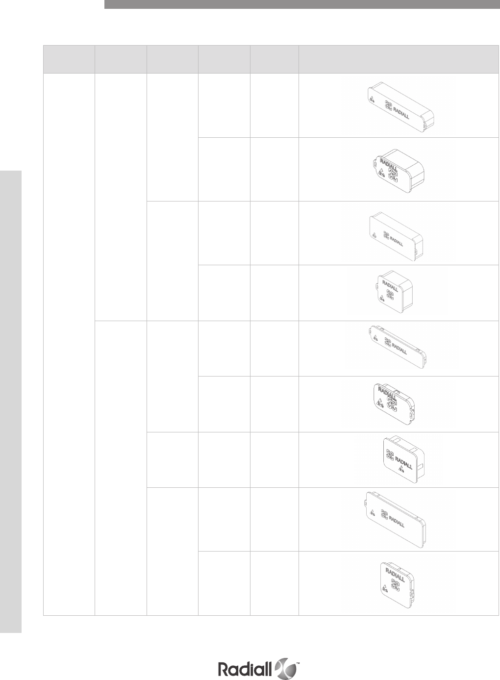
Electrical
characteristics Shell type Shell size Shell cavity Part number Figure
Conductive
Plug
1
A/B 620995003
C620995004
2 & 3
A/B & D/E 620995007
C & F 620995008
Receptacle
1
A/B 620995011
C620995012
For single shell
connector -620995018
2 & 3
A/B & D/E 620995015
C & F 620995016
DUST CAPS
Accessories
Dust caps are made of thermoplastic. They are available either conductive (black color) or not (red color).
NSX SERIES
4-86
Our Most Important Connection is with You.™
Go online for data sheets & assembly instructions. Visit www.radiall.com and enter the part number.
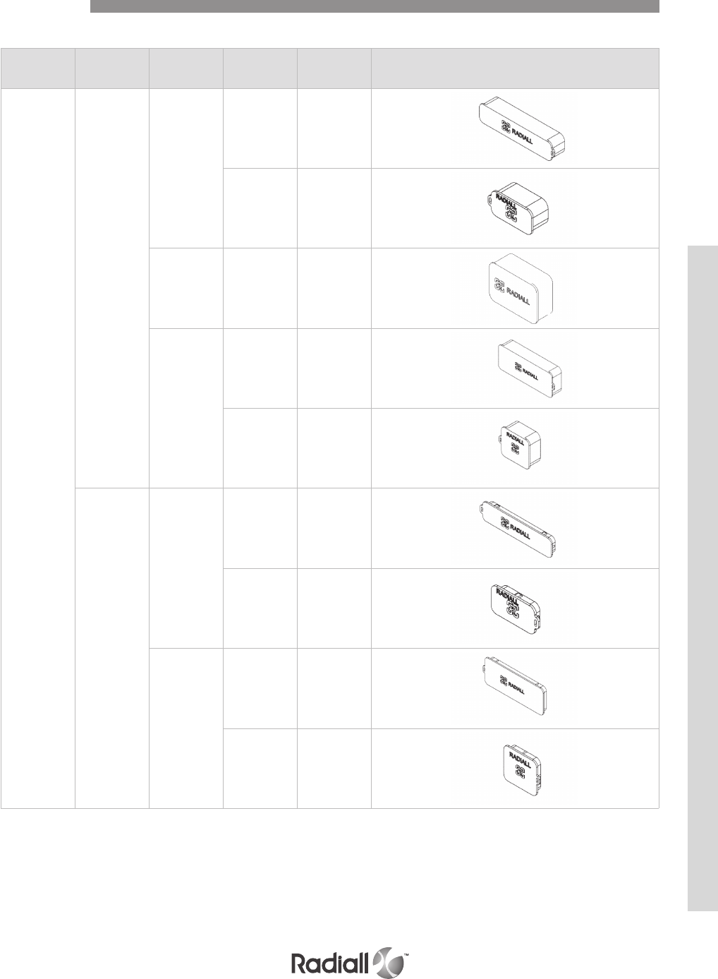
Electrical
characteristics Shell type Shell size Shell cavity Part number Figure
Non
conductive
Plug
1
A/B 620995001
C620995002
For single shell
connector -620995017
2 & 3
A/B & D/E 620995005
C & F 620995006
Receptacle
1
A/B 620995009
C620995010
2 & 3
A/B & D/E 620995013
C & F 620995014
DUST CAPS
Accessories
NSX SERIES
4-87
Our Most Important Connection is with You.™
Go online for data sheets & assembly instructions. Visit www.radiall.com and enter the part number.
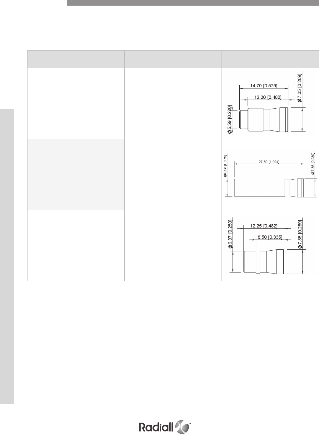
Electrical
characteristics Part number Figure
For pin contact 620940
For socket contact 620941
For pin contact front release / front removable
(FR/FR) connector in version G 620942
CAVITY REDUCERS
The following parts are cavity reducers which allows the use of a size 12 contact in a size 5 cavity.
These parts are made of copper alloy and are plated with gold over nickel.
Once installed, they cannot be removed.
Accessories
NSX SERIES
4-88
Our Most Important Connection is with You.™
Go online for data sheets & assembly instructions. Visit www.radiall.com and enter the part number.
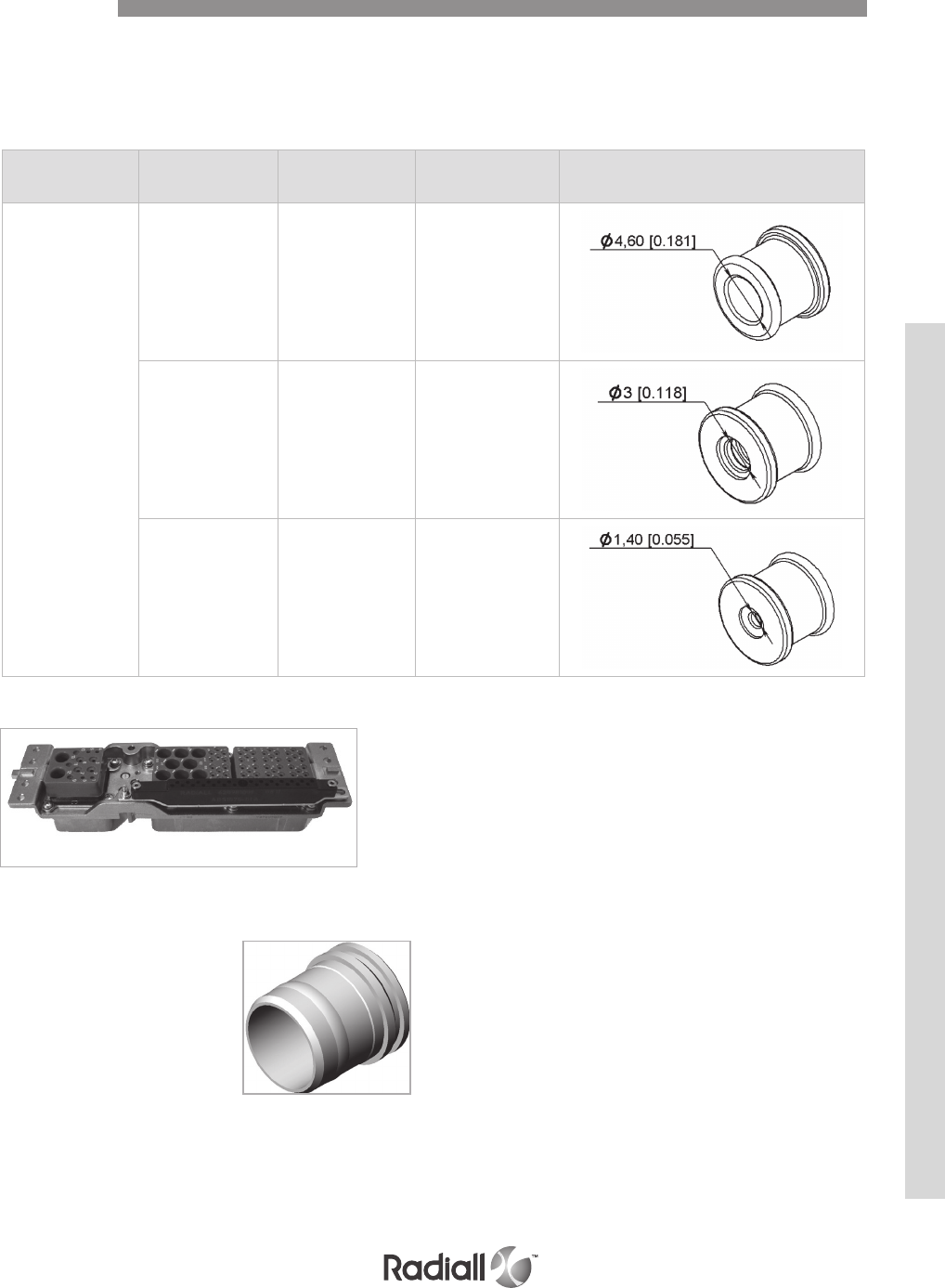
Electrical
characteristics
Cable outside dia.
mm (inch) Cable Part number Figure
5
5 (0.197)
RG 58
RG 141
RG 142
RG 223
RG 400
620939201
3.81 (0.150) RG 180
RG 195 620939200
2.59 (0.102)
& 2.01 (0.079)
RG 179
RG 316
KX 21
620914001
SEALING BOOTS
The sealing boots are designed to slide down over the back of the crimped contacts after they have been
installed in the connector. The assembly provides bend support and moisture sealing to the contact /
cable assembly. Sealing boots are made of fluorosilicon rubber.
ALIGNMENT BOOTS (part number 619960)
Alignment boots are designed to reduce
the play at the top of the size 8 pin contacts.
They are used with non environmental rear
release/ rear removable size 8 pin contacts.
GROUNDING BLOCK (part number 620981002)
Radiall provides a unique feature by integrating a ground
block directly on the plug shell for sizes #2 & #3.
This option allows very short ground terminations.
Pin crimp ground contacts are available with grounding
block, part number is 620260
(up to 26 contacts per grounding block).
Accessories
NSX SERIES
4-89
Our Most Important Connection is with You.™
Go online for data sheets & assembly instructions. Visit www.radiall.com and enter the part number.
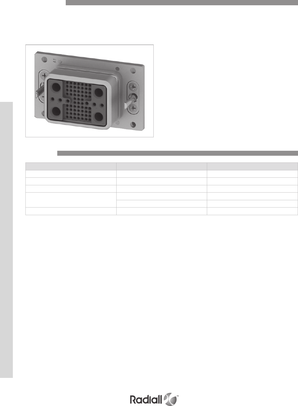
NSX – SINGLE SHELL CONNECTOR
NSX single shell connectors are designed to accommodate all large cavity inserts.
Their characteristics are shown on page 4-8 except for the following.
Description Material Plating
Shell Aluminum alloy Cadmium clear chromate or nickel
Insert retention plate Aluminum alloy Cadmium clear chromate or nickel
Polarization posts and keys retention plate Aluminum alloy Cadmium clear chromate or nickel
Screws washers and clinch-nuts Stainless steel /
Steel Cadmium clear chromate
Polarization posts and keys Zinc alloy Cadmium yellow chromate or nickel
Introduction
Materials
NSX SERIES
4-90
Our Most Important Connection is with You.™
Go online for data sheets & assembly instructions. Visit www.radiall.com and enter the part number.
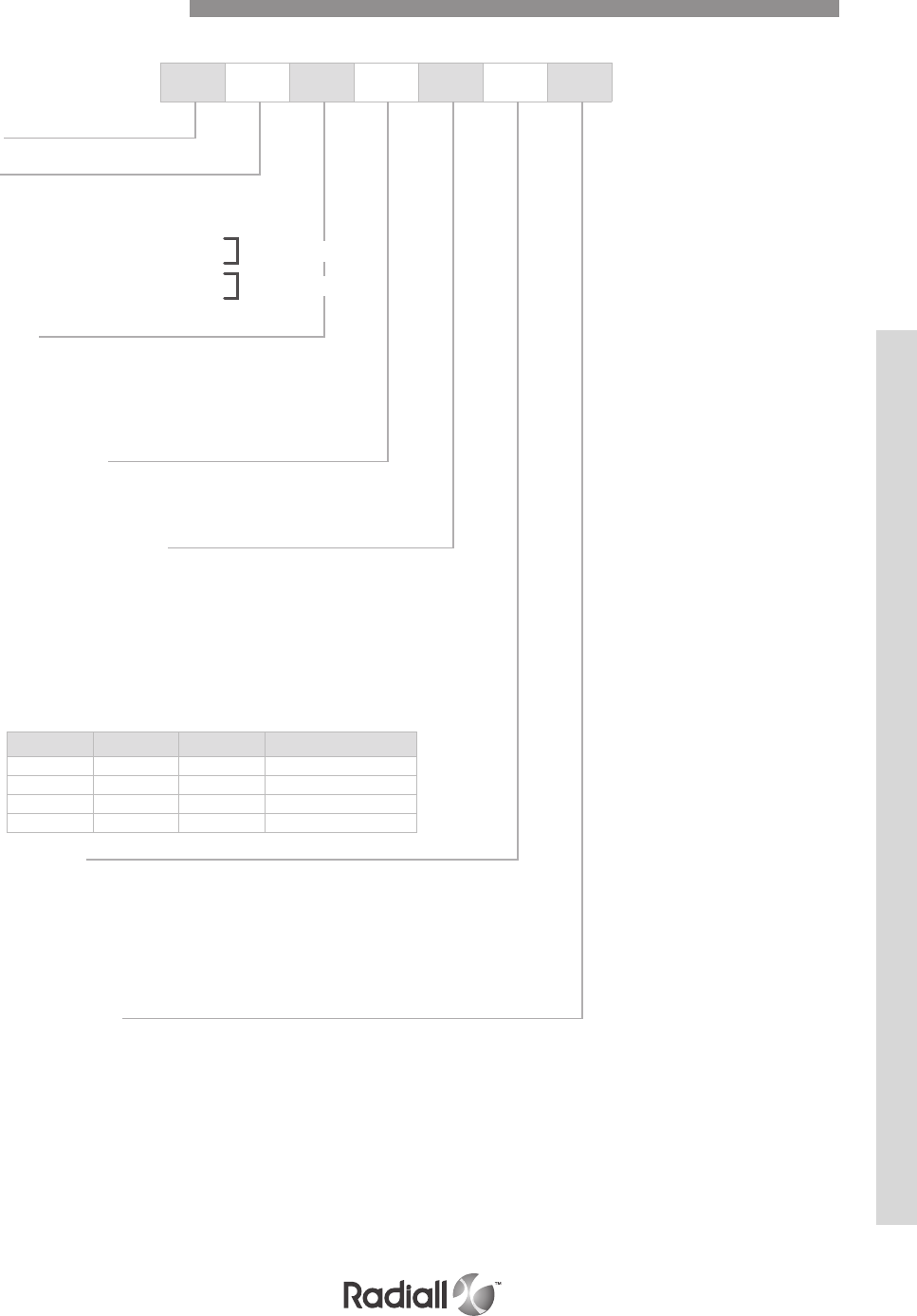
NSX N P 150 S 00 01
NOTES:
(1) For F class receptacle,only size 22 contacts can be delivered in PC Tail version, others contacts (size 20, 16, 12) will be delivered in crimp
version. Coaxial, twinax and quadrax contacts are ordered separately
For G class receptacle, every contacts can be delivered in PC Tail or crimp version except size 1 that will be delivered in crimp version only.
Coax twinax and power contacts size are ordered separately
(2) Without polarization code, the connector is delivered polarization hardware unassembled
Polarization code 00, the connector is delivered without polarization hardware.
Polarization code 01 to 36, the connector is delivered with the polarization hardware assembled as defined by the code
NSX – SINGLE SHELL CONNECTOR
How to Order Connector
NSX SERIES
4-91
Our Most Important Connection is with You.™
Go online for data sheets & assembly instructions. Visit www.radiall.com and enter the part number.
Series
Class
N: Non environmental (rear removable version only)
E: Environmental, with grommets and compound.
plug with O-ring (rear removable version only).
H: Environmental plug without O-ring
C: Non environmental with grommets
F: Non environmental receptacle shell
G: Non environmental receptacle shell
Shell style
R: Cadmium clear chromate plated receptacle
P: Cadmium clear chromate plated plug
F: Nickel plated receptacle
B: Nickel plated plug
M: Nickel plated plug EMI/RF1 solution (see page 4-96)
Contact arrangement
See contact arrangements on pages 4-12 to 4-21
Only use insert for A & B cavities
Contacts termination (1)
Without contacts
X: Without contacts
S: Crimp contacts
Wire wrap
K: Wire wrap contact, 1 level (1 = .272)
V: Wire wrap contact, 2 levels (1 = .390)
W: Wire wrap contact, 3 levels (1 = .524)
PC tail contacts
RoHs Gold Pre-tinned Length (inch)
RA YA ZA .150
R Y Z .250
RB YB ZB .375
RC YC ZC .500
Modification code
00: 4 mounting holes .146/.156 dia
01: 4 clinch nuts 4.40 UNC
03: 4 each .122 dia mounting holes c’sunk .230 dia x 100°
04: 4 each .122 dia mounting holes c’sunk .230 dia x 82°
05: 4 each .137 dia mounting holes c’sunk .230 dia x 82°
23: 4 floating eyelets .122 - .126 dia
Polarization code (2)
See pages 4-92 to 4-93
Without code: polarization hardware is delivered unassembled
rear removable
front removable
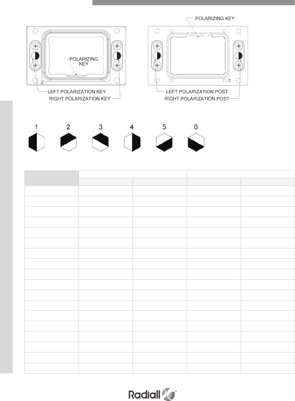
MATING FACE
Position Equipment receptacle Rack plug
Le. key Right. key Le. post Right. post
01
02
1
3
1
4
1
4
1
5
03
04
2
1
4
4
4
4
6
1
05
06
6
5
4
4
4
4
2
3
07
08
4
3
5
5
3
3
4
5
09
10
2
1
5
5
3
3
6
1
11
12
6
5
5
5
3
3
2
3
13
14
4
3
6
6
2
2
4
5
15
16
2
1
6
6
2
2
6
1
17
18
6
5
6
6
2
2
2
3
19
20
4
3
1
1
1
1
4
5
21
22
2
4
1
4
1
4
6
4
23
24
6
5
1
1
1
1
2
3
25
26
4
3
2
2
6
6
4
5
27
28
2
1
2
2
6
6
6
1
29
30
6
5
2
2
6
6
2
3
31
32
4
3
3
3
5
5
4
5
33
34
2
1
3
3
5
5
6
1
35
36
6
5
3
3
5
5
2
3
POSITION OF POST (DARK) AND KEYHOLE (LIGHT)
Horizontal Installation
NSX SERIES
4-92
Our Most Important Connection is with You.™
Go online for data sheets & assembly instructions. Visit www.radiall.com and enter the part number.
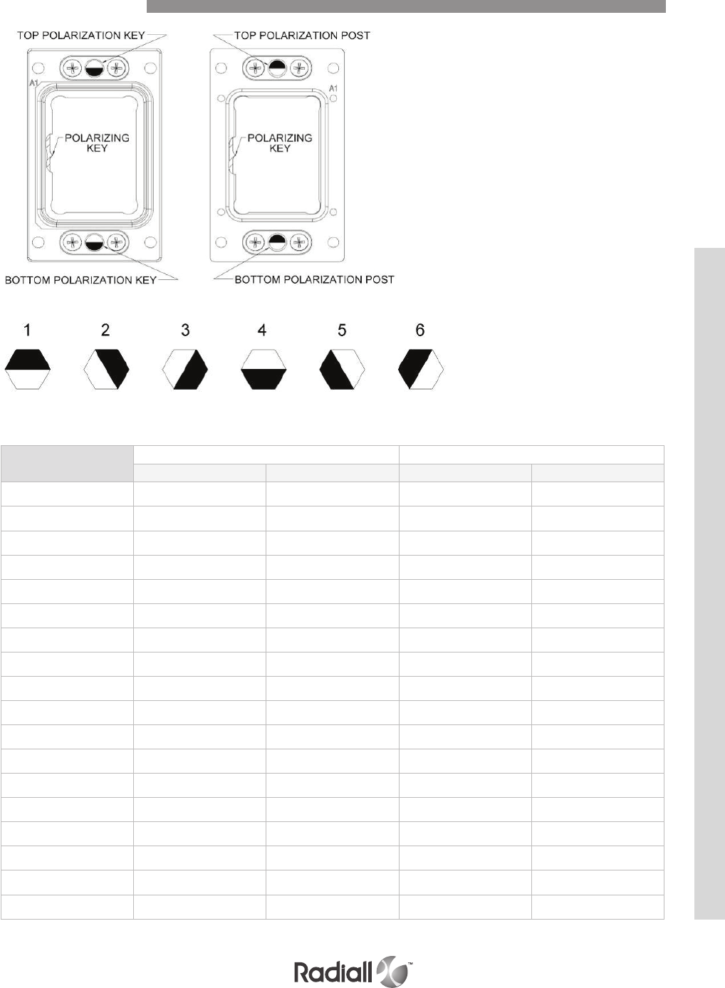
MATING FACE
Position Equipment receptacle Rack plug
Le. key Right. key Le. post Right. post
01
02
1
3
1
4
4
2
4
1
03
04
2
1
4
4
3
4
1
1
05
06
6
5
4
4
5
6
1
1
07
08
4
3
5
5
1
2
6
6
09
10
2
1
5
5
3
4
6
6
11
12
6
5
5
5
5
6
6
6
13
14
4
3
6
6
1
2
5
5
15
16
2
1
6
6
3
4
5
5
17
18
6
5
6
6
5
6
5
5
19
20
4
3
1
1
1
2
4
4
21
22
2
4
1
4
3
1
4
1
23
24
6
5
1
1
5
6
4
4
25
26
4
3
2
2
1
2
3
3
27
28
2
1
2
2
3
4
3
3
29
30
6
5
2
2
5
6
3
3
31
32
4
3
3
3
1
2
2
2
33
34
2
1
3
3
3
4
2
2
35
36
6
5
3
3
5
6
2
2
POSITION OF POST (DARK) AND KEYHOLE (LIGHT)
Vertical Installation
NSX SERIES
4-93
Our Most Important Connection is with You.™
Go online for data sheets & assembly instructions. Visit www.radiall.com and enter the part number.
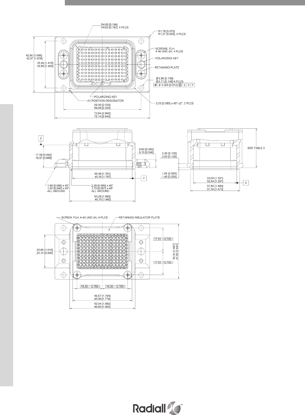
NSX SINGLE SHELL RECEPTACLE DIMENSIONS
Dimensions
NSX SERIES
4-94
Our Most Important Connection is with You.™
Go online for data sheets & assembly instructions. Visit www.radiall.com and enter the part number.
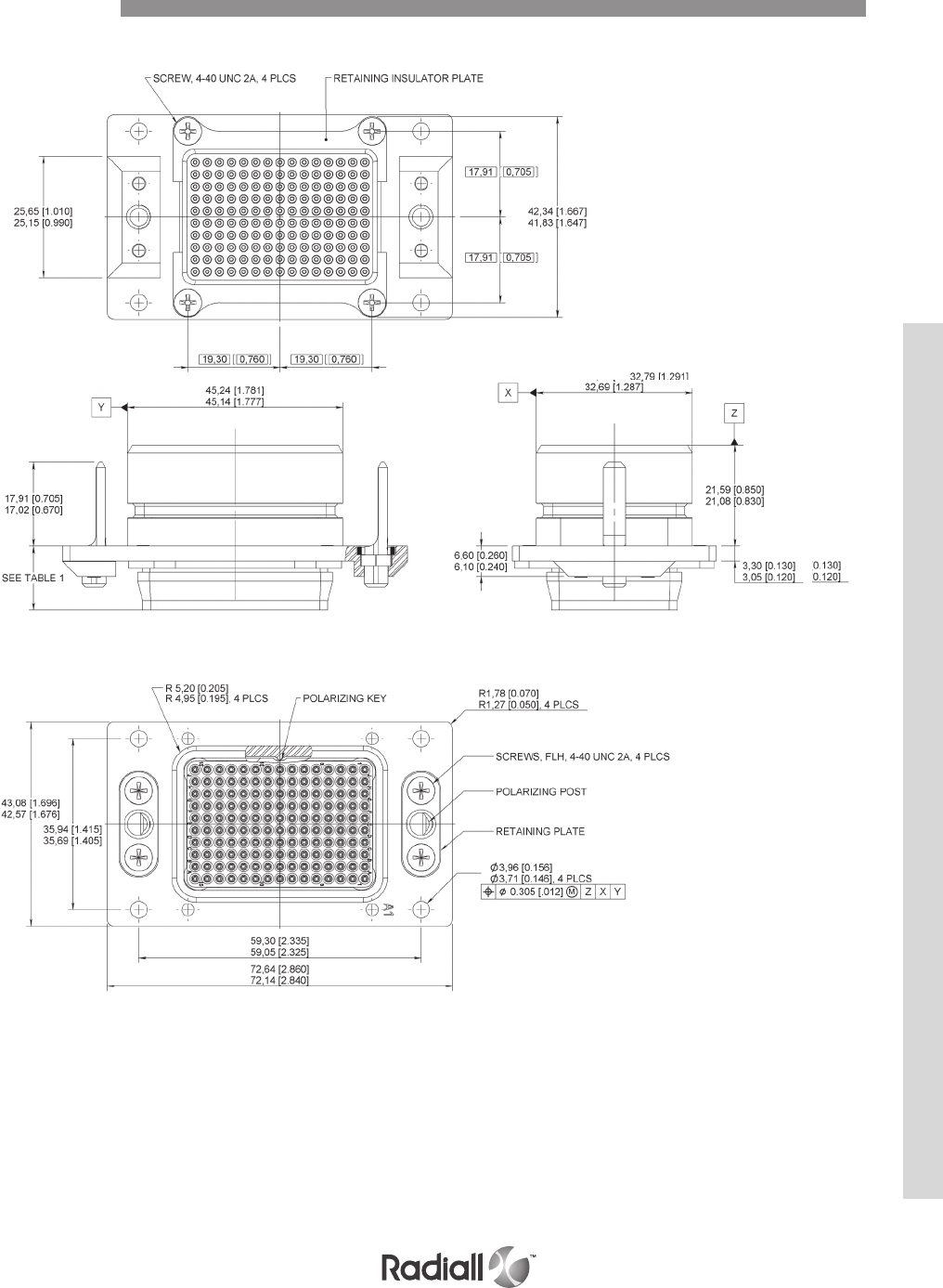
NSX SINGLE SHELL PLUG DIMENSIONS
Dimensions
NSX SERIES
4-95
Our Most Important Connection is with You.™
Go online for data sheets & assembly instructions. Visit www.radiall.com and enter the part number.
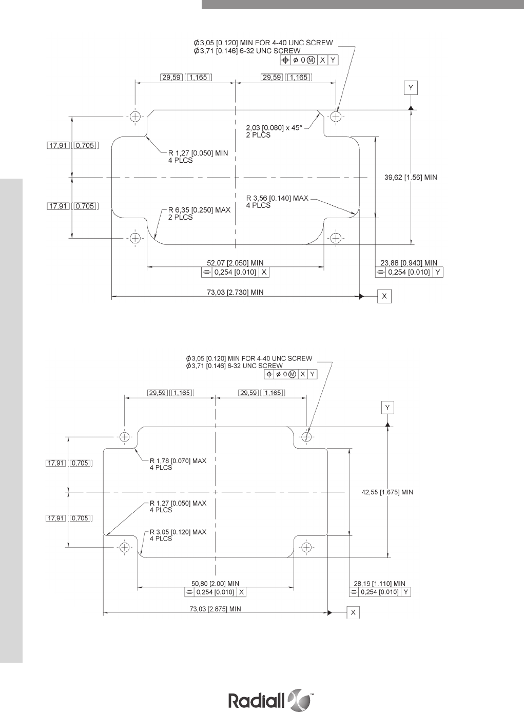
RECEPTACLE PANEL CUT OUT
PLUG PANEL CUT OUT
NSX Single Shell Panel Cut Out
NSX SERIES
4-96
Our Most Important Connection is with You.™
Go online for data sheets & assembly instructions. Visit www.radiall.com and enter the part number.
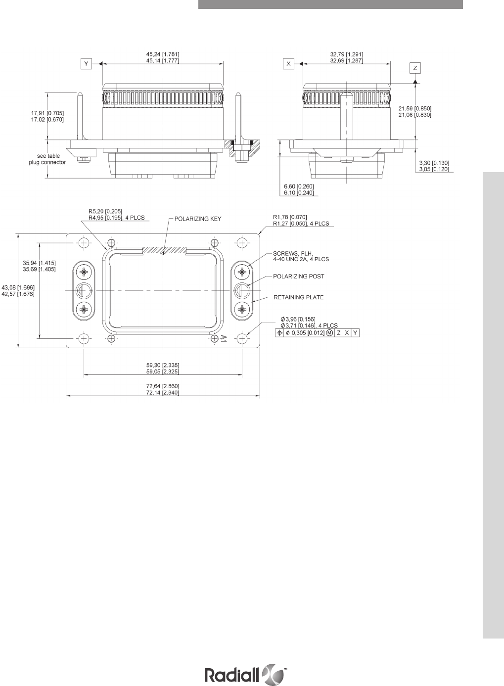
HOW TO ORDER
See page 4-91
EMI/RFI NSX Single Shell Plug Dimension
NSX SERIES
4-97
Our Most Important Connection is with You.™
Go online for data sheets & assembly instructions. Visit www.radiall.com and enter the part number.
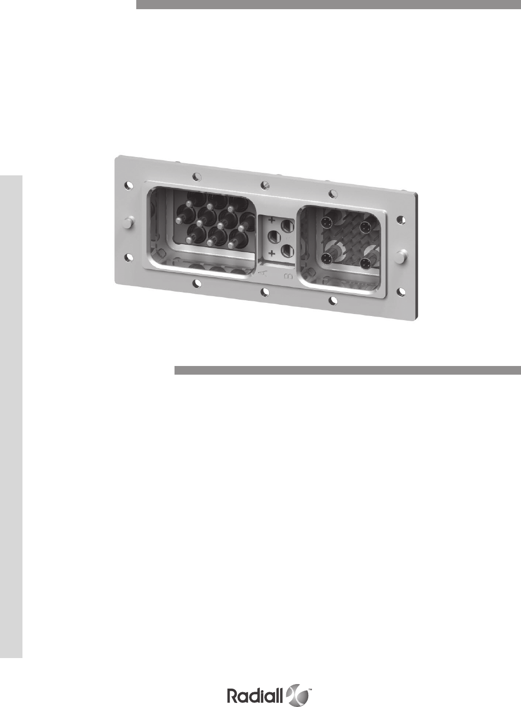
BPX series connectors are EMI shielded and modular insert concept rectangular
multipin connectors fitted with NSX inserts and contacts.
BPX connectors are differentiated from NSX connectors by their shell sizes available: 1, 2 and 3.
The BPX characteristics are compliant to BOEING S280W551 specification. Their specific
characteristics (those which are different from NSX connectors) are as follows:
BPX electrical characteristics are the same as NSX connectors (see pages 4-8 to 4-9) except the following:
- Magnetic permeability: 2.0 Ohms max.
BPX Introduction
Electrical Characteristics
BPX SERIES
4-98
Our Most Important Connection is with You.™
Go online for data sheets & assembly instructions. Visit www.radiall.com and enter the part number.

Identical to NSX connectors except the following:
Mating and unmating forces:
- Shell size 1: 70 pounds (311 N) max
- Shell size 2: 140 pounds (623 N) max
- Shell size 3: 130 pounds (578 N) max
Humidity: type II
(measured according to method 1002 of MIL-STD-1344A)
Fluid resistance: resistance to MIL-STD-1344A method 1016 (fluids a, e, i, j).
Contact stability: conforming to S280W551 requirements.
Description Material Plating
Shell Aluminum alloy Electrically conductive finish over nickel
Grounding spring fingers Copper alloy Nickel
Insert retention plate Aluminum alloy Nickel
Polarization posts and keys retention plate Aluminum alloy Nickel
Screws, washers and clinch nuts Stainless steel
Polarization posts and keys Zinc alloy Nickel
Mechanical and Environmental Characteristics
Materials
BPX SERIES
4-99
Our Most Important Connection is with You.™
Go online for data sheets & assembly instructions. Visit www.radiall.com and enter the part number.
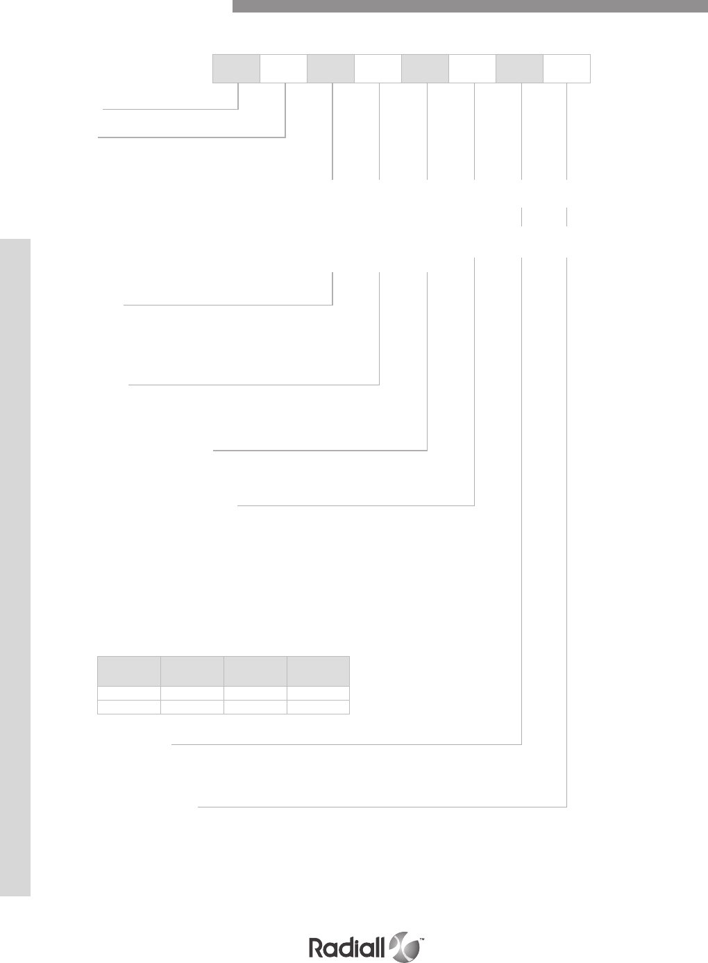
BPX E 2 P 201 S 00 01
NOTE:
(1) Polarization code 00, the connector is delivered without polarization hardware. Polarization code 01 to 216, the connector is delivered
with the polarization hardware as defined by the code
BPX N/E/F/G CONNECTORS FOR REAR REMOVABLE CONTACTS
Series
Class
N: Non environmental
E: Environmental
F: Non environmental receptacle connectors only for F class receptacle, only size 22 contacts
can be delivered in PC Tail version, others contacts (size 20, 16, 12) will be delivered in
crimp version. Coaxial, twinax and quadrax contacts shall to be ordered separately.
G: Non environmental receptacle connectors only for G class receptacle, every contacts can
be delivered in PC Tail or crim version except size 1 that will be delivered in crimp version
only. Coax, twinax and power contacts size shall be ordered separately.
Shell size
1: 2 cavities
2: 4 cavities
3: 5 cavities
Shell style
R: Receptacle
P: Plug
Insert combination code
See insert combination codes on page 4-100
Contacts termination (1)
Without contacts
X: Without contacts
S: Crimp contacts
Wire wrap
K: Wire wrap contact, 1 level (1 = .272)
V: Wire wrap contact, 2 levels (1 = .390)
PC tail contacts
Modification code
00: Only modification code 00 is available, see page 4-29
Polarization code (1)
See pages 4-31 to 4-33
Without code: polarization hardware is delivered unassembled
How to Order Connector
RoHs Gold Pre-tinned Length
(inch)
RA YA ZA .150
R Y Z .250
BPX SERIES
4-100
Our Most Important Connection is with You.™
Go online for data sheets & assembly instructions. Visit www.radiall.com and enter the part number.
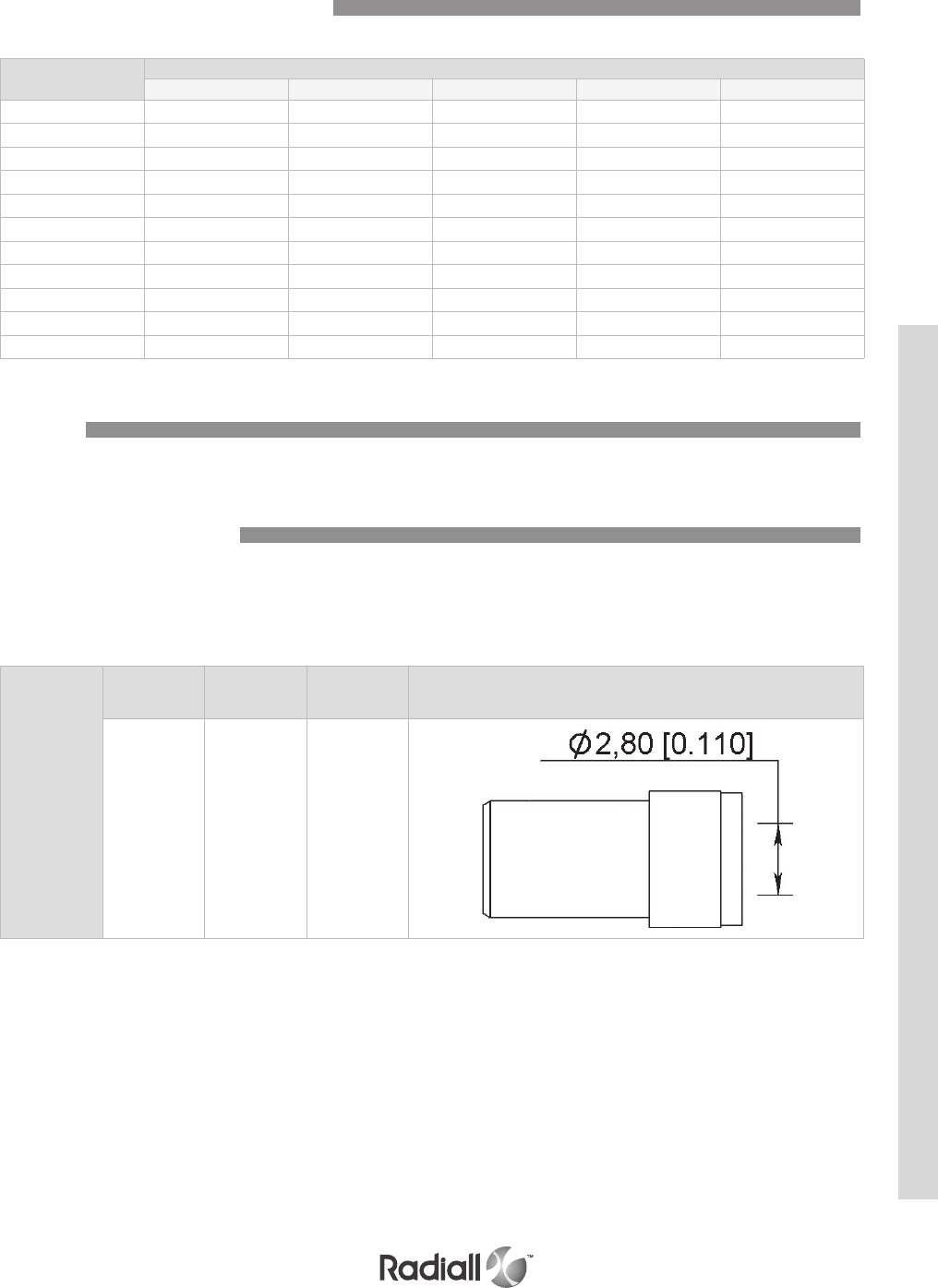
Code Insert combination on shell
A B C D E
101 10T10 34 / / /
102 10T10 59 / / /
103 150 13C2 / / /
201 150 100 150 6T6 /
202 121 6T6 150 6T6 /
203 10T10 100 10T10 100 /
204 121 6T6 121 6T6 /
205 110 6T6 150 6T6 /
301 10T10 4 6P6 60A 4
302 10T10 30T2 6P6 60A 30T2
303 120T2 46P6 60A 4
Insert Combination Code in the Shell
Sealing boot
for cavity insert
size 8
Wire dia
mm (inch) Wire type Part number Figure
3.68 (0.145) Tensolite
(S280W502-1) 619960005
The sealing boots are designed to slide down over the back of crimped contacts after they have been
installed in the connector. The assembly provides bend support and moisture sealing to the contact/
cable assembly. For BPX connectors size, 8 coaxial and concentric twinax contacts must be fitted with
the sealing boot required by S280W552 specification.
Accessories - Sealing Boot
BPX connectors use NSX signal, power coaxial and concentric twinax contacts (see pages 4-34 to 4-57).
Contact
BPX SERIES
4-101
Our Most Important Connection is with You.™
Go online for data sheets & assembly instructions. Visit www.radiall.com and enter the part number.
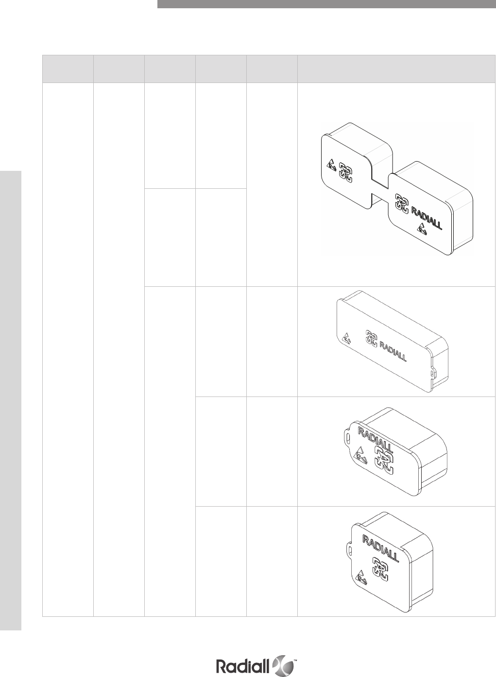
Type Shell type Shell size Cavity Part number Figure
Conductive Plug
1A and B
618953002
2A and B
C and D
3
A, D 620995007
B, E 620995004
C620995008
Dust caps are made of thermoplastic material, they are either conductive (black color) or
non-conductive (red color).
Accessories - Dust Caps
BPX SERIES
4-102
Our Most Important Connection is with You.™
Go online for data sheets & assembly instructions. Visit www.radiall.com and enter the part number.
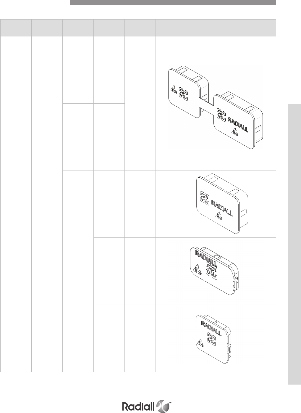
Type Shell type Shell size Cavity Part number Figure
Conductive Receptacle
1A and B
618953001
2A and B
C and D
3
A, D 620995018
B, E 620995012
C620995016
Accessories - Dust Caps
BPX SERIES
4-103
Our Most Important Connection is with You.™
Go online for data sheets & assembly instructions. Visit www.radiall.com and enter the part number.
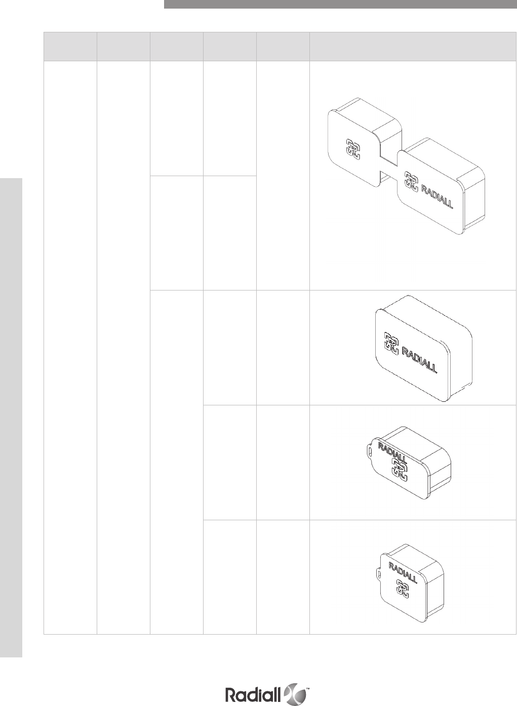
Type Shell type Shell size Cavity Part number Figure
Non conductive Plug
1A and B
618953
2A and B
C and D
3
A, D 620995017
B, E 620995002
C620995006
Accessories - Dust Caps
BPX SERIES
4-104
Our Most Important Connection is with You.™
Go online for data sheets & assembly instructions. Visit www.radiall.com and enter the part number.
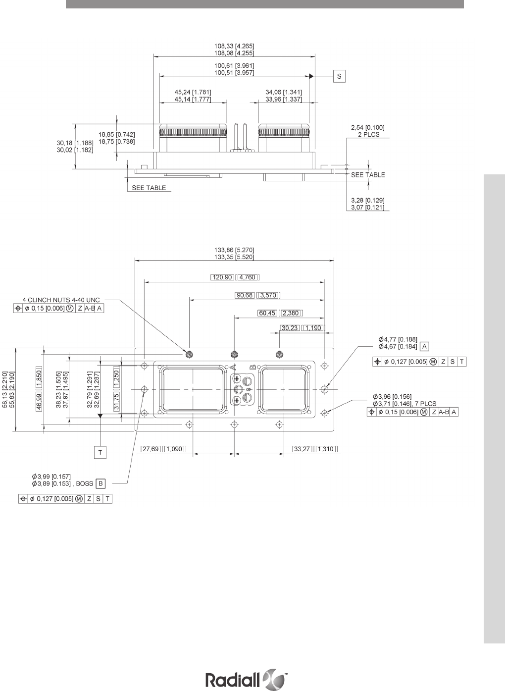
SIZE 1 PLUG DIMENSIONS
Dimensions
BPX SERIES
4-105
Our Most Important Connection is with You.™
Go online for data sheets & assembly instructions. Visit www.radiall.com and enter the part number.

SIZE 2 PLUG DIMENSIONS
Dimensions
BPX SERIES
4-106
Our Most Important Connection is with You.™
Go online for data sheets & assembly instructions. Visit www.radiall.com and enter the part number.
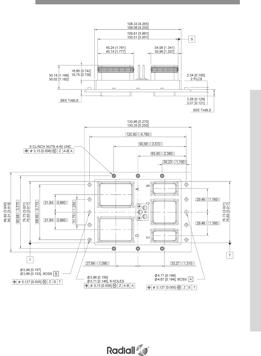
SIZE 3 PLUG DIMENSIONS
Dimensions
BPX SERIES
4-107
Our Most Important Connection is with You.™
Go online for data sheets & assembly instructions. Visit www.radiall.com and enter the part number.
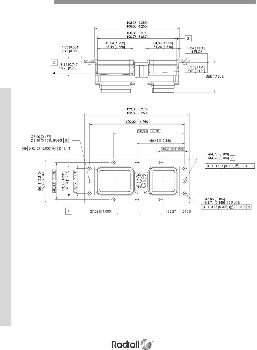
SIZE 1 RECEPTACLE DIMENSIONS
Dimensions
BPX SERIES
4-108
Our Most Important Connection is with You.™
Go online for data sheets & assembly instructions. Visit www.radiall.com and enter the part number.
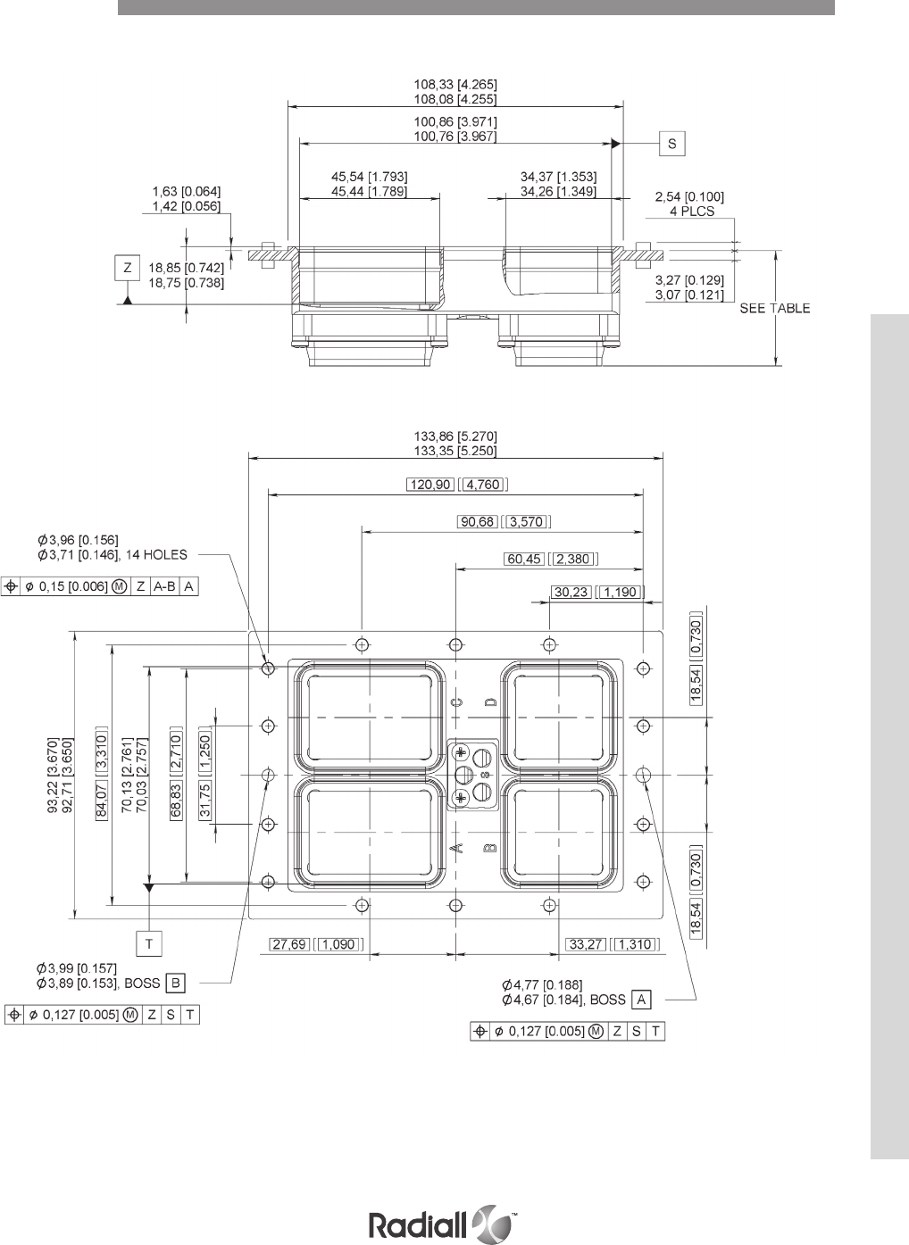
SIZE 2 RECEPTACLE DIMENSIONS
Dimensions
BPX SERIES
4-109
Our Most Important Connection is with You.™
Go online for data sheets & assembly instructions. Visit www.radiall.com and enter the part number.
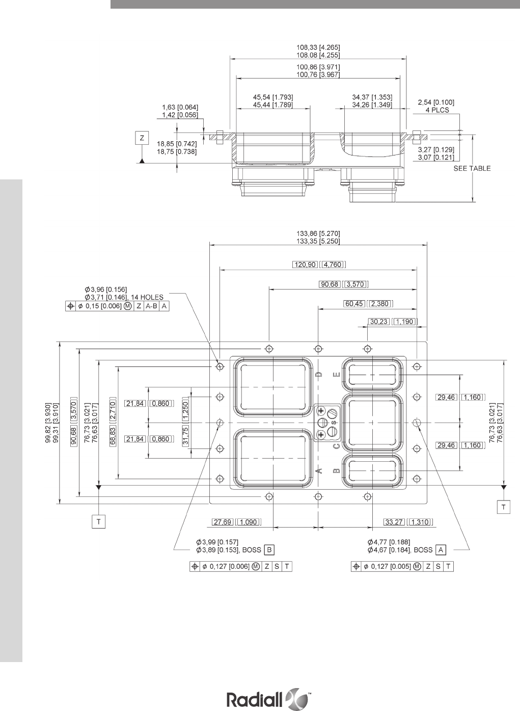
SIZE 3 RECEPTACLE DIMENSIONS
Dimensions
BPX SERIES
4-110
Our Most Important Connection is with You.™
Go online for data sheets & assembly instructions. Visit www.radiall.com and enter the part number.
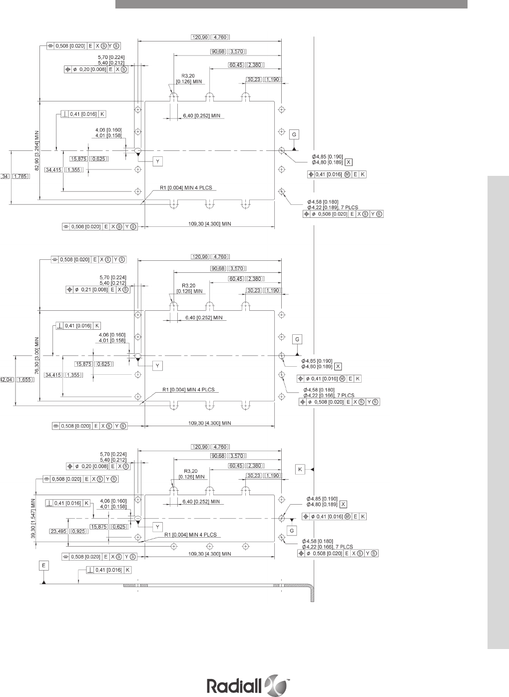
Panel Cut Out for Plug
BPX SERIES
4-111
Our Most Important Connection is with You.™
Go online for data sheets & assembly instructions. Visit www.radiall.com and enter the part number.
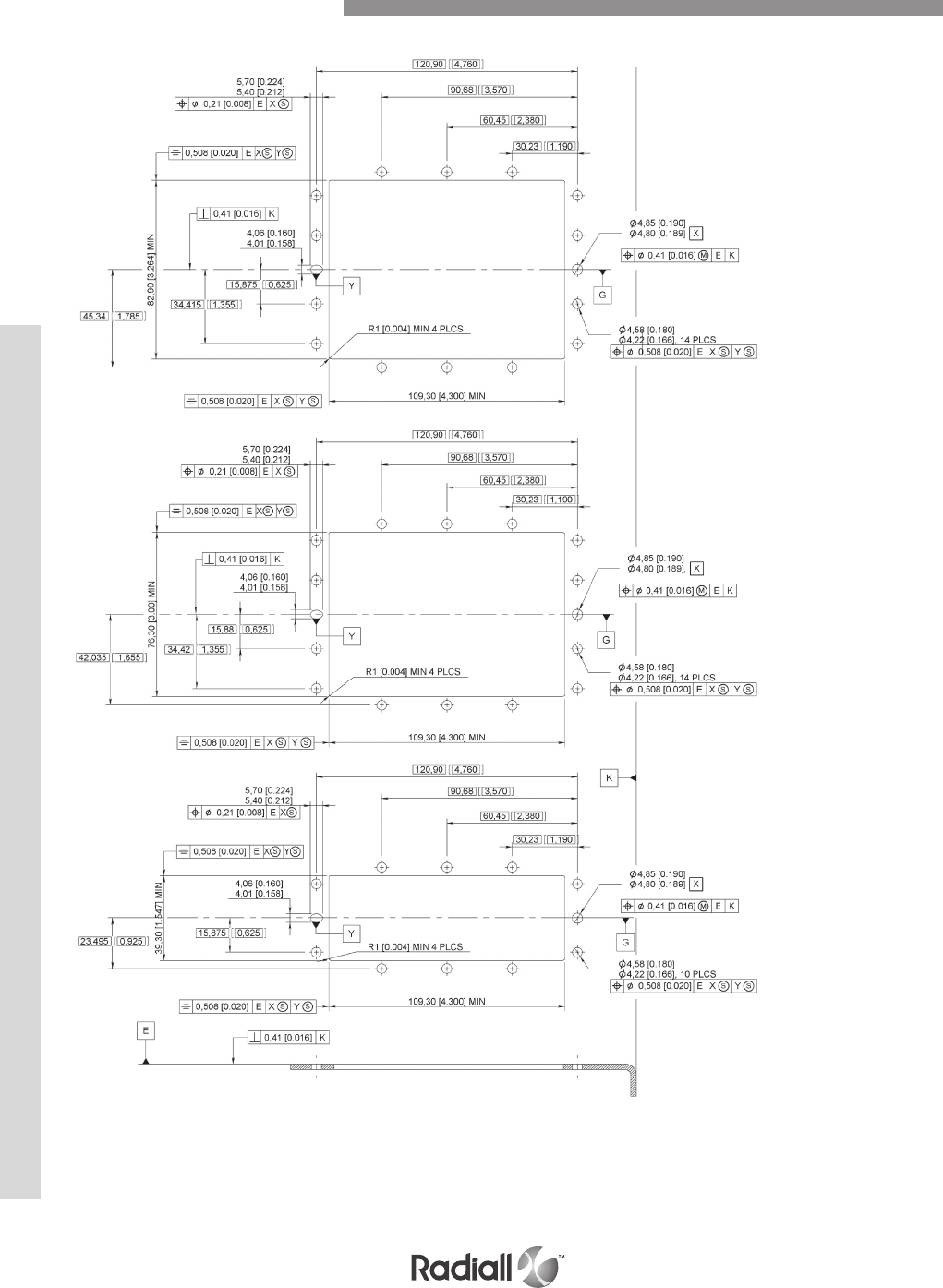
Panel Cut Out for Receptacle
BPX SERIES
4-112
Our Most Important Connection is with You.™
Go online for data sheets & assembly instructions. Visit www.radiall.com and enter the part number.
MPX Series
SECTION 5
MIL- DT L- 83527B
AECMA EN3682

Our Most Important Connection is with You.™

Introduction ..................................................................................................................... 5-4
Applications ..................................................................................................................... 5-4
Product overview ............................................................................................................... 5-5
Technical characteristics ....................................................................................................... 5-6
Shell ordering information ..................................................................................................... 5-8
Insert ordering information .................................................................................................... 5-9
Connector ordering information ............................................................................................. 5-10
Insert combination code ..................................................................................................... 5-11
Inserts layouts cavaties A, C, or E ........................................................................................... 5-14
Inserts layouts cavities B, D, or F ............................................................................................ 5-18
Modification code ............................................................................................................. 5-21
Polarization code ............................................................................................................. 5-22
Contacts ....................................................................................................................... 5-23
Accessories ................................................................................................................... 5-33
Dimensions
- Shell 2 dimensions .......................................................................................................... 5-35
- Shell 3 dimensions .......................................................................................................... 5-38
- Shell 4 dimensions .......................................................................................................... 5-40
Panel cut-out .................................................................................................................. 5-42
Part numbers index ........................................................................................................... 5-44
Contents
SECTION 5 TABLE OF CONTENTS
5-3
Our Most Important Connection is with You.™
Go online for data sheets & assembly instructions Visit www.radiall.com and enter the part number

The Radiall MPX series is a robust rectangular connector designed to meet all the requirements of the
MIL-DTL-83527B specification. The design conforms to the EN 3682 European Standard as well. This
series is well suited for military and commercial aircraft applications where harsh environmental issues
are a concern. Connectors, shells, inserts termination modules and contacts are sold separately or fully
assembled.
©Eurocopter – Jérome Deulin
©Dassault Aviation – F. Robineau
©Eurocopter -
Remy Michelin
Introduction
Applications
These connectors are used to form the mechanical and electrical interface between the avionics equipment
box and the rack.
MPX SERIES
5-4
Our Most Important Connection is with You.™
Go online for data sheets & assembly instructions Visit www.radiall.com and enter the part number
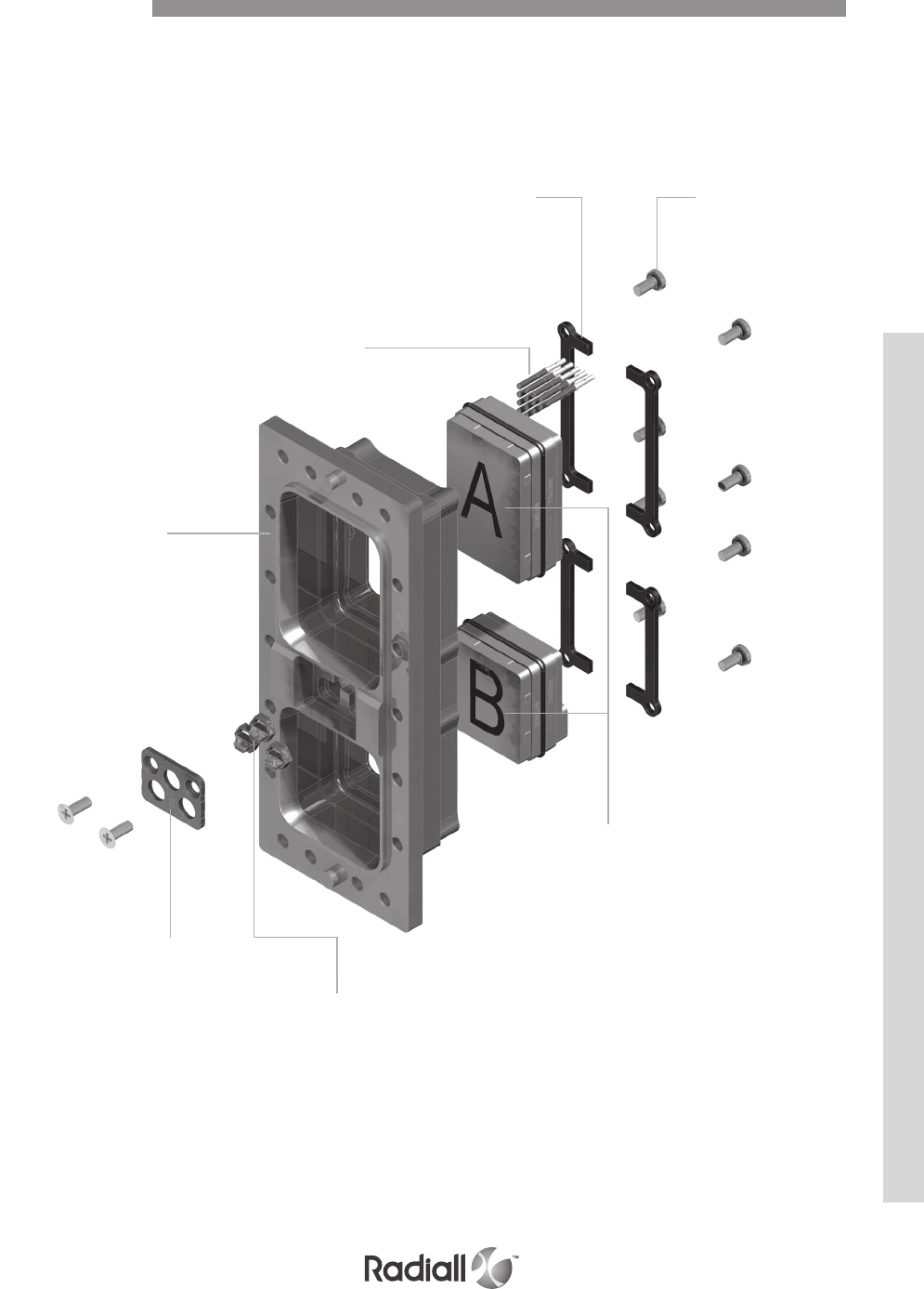
Detailed view of the various parts of an MPX connector.
Insert
Retention
Plates Screws
Contacts
Shell
Polarization
Plate
Polarization
keys
Inserts
Product Overview
MPX SERIES
5-5
Our Most Important Connection is with You.™
Go online for data sheets & assembly instructions Visit www.radiall.com and enter the part number
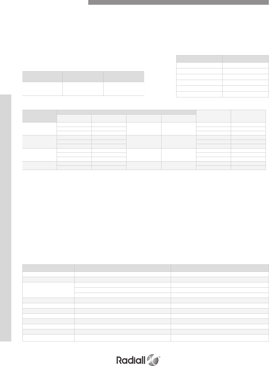
ELECTRICAL
MECHANICAL & ENVIRONMENTAL
- Temperature range: 65°C (-85°F) to +150°C (+302°F)
- Temperature life : (see MIL-DTL-83527B): 1000 hours at 150°C (+302°F)
- Salt spray (Test procedure 26 of EIA364): 500 hours
- Humidity (Test procedure 31 of EIA364): 10 days
- Shock (Test procedure 27 of EIA364): 30g / 11ms / half sine
- Vibration: see MIL-DTL-83527B
- Mating & unmating: (Test procedure 9 of EIA364): 500 cycles
- Mating & unmating forces: Shell size 2 1446 N / 325 lbf max
Shell size 3 1780 N / 400 lbf max
Shell size 4 2113 N / 475 lbf max
Contact sizes At sea level Altitude (1.1 k Pa)
# 22
Other contacts 1 300
1 500 800
800
DIELECTRIC WITHSTANDING VOLTAGE
(Test procedure 20 of EIA364): (Vrms)
Frequency (Mhz) Attenuation (dB)
100 65
200 65
300 63
400 62
800 60
1000 60
EMI SHIELDING EFFECTIVENESS
(MIL-DTL-83527B)
CONTACTS RESISTANCE (Test procedure 23 and 06 of EIA364)
Contact size
Wire
Max current (A) Contact
resistance (mΩ)
AWG Cross section (mm2)Min diameter inch
(mm)
Max diameter inch
(mm)
22
22 0.38
.030 (0.76) .052 (1.32)
5 17
24 0.21 3 23
26 0.14 2 38
20
20 0.60
.035 (0.89) .060 (1.52)
7.5 11
22 0.38 5 17
24 0.21 3 23
16
16 1.34
.048 (1.21) .080 (2.03)
13 6
18 0.91 10 8
20 0.60 7.5 10
12 12 3.18 .091 (4.85) .216 (5.49) 23 3.35
14 1.91 17 4.24
Technical Characteristics
MATERIALS
Description Material Finish
shell and backshell aluminium alloy
cadmium yellow chromate over electroless nickel
contacts copper alloy
gold over electroless nickel
inserts
thermosetting resin
/
high grade thermoplatic
/
aluminium
cadmium yellow chromate over electroless nickel
retention clip copper alloy
/
seals and o-ring fluorinated silicon rubber
/
insert retention plate aluminium alloy
blue anodized
polarization key zinc alloy
cadmium olive drab
polarization post aluminium alloy
cadmium yellow chromate
screws brass
cadmium yellow chromate
washers copper alloy
cadmium yellow chromate
EMI spring copper alloy & fluorinated silicon rubber
tin-lead alloy over electroless nickel
- Insulation resistance (Test procedure 21 of EIA364) : ≥ 1000MΩ - 500Vdc
- Shell to shell conductivity (Test procedure 83 of EIA364): ≤ 2.5mOhms
- Size 8 grounding (Test procedure 83 of EIA364): ≤ 10mOhms
MPX SERIES
5-6
Our Most Important Connection is with You.™
Go online for data sheets & assembly instructions Visit www.radiall.com and enter the part number
MASSES
Receptacle g (oz)
Shell size 2 Shell size 3 Shell size 4
160 (5.64) 240 (8.47) 335 (11.82)
Plug g (oz)
Shell size 2 Shell size 3 Shell size 4
165 (5.82) 245 (8.64) 342 (12.06)
Description Insert for plug shell g (oz) Insert for receptacle shell g (oz)
MPXE2*T6 44 (1.55) 26 (0.92)
MPXE2*11T2 41 (1.45) 25 (0.88)
MPXE2*11C2 41 (1.45) 25 (0.88)
MPXE2*20T4 37 (1.31) 22 (0.78)
MPXE2*34 44 (1.55) 27 (0.95)
MPXE2*62T2 34 (1.20) 22 (0.78)
MPXE2*100 25 (0.88) 21 (0.74)
MPXE1*24 51 (1.80) 31 (1.10)
MPXE1*C12T6 55 (1.94) 33 (1.17)
MPXE1*47T2 57 (2.01) 35 (1.24)
MPXE1*60 63 (2.23) 39 (1.38)
MPXE1*126 47 (1.66) 31 (1.10)
MPXE1*150 41 (1.45) 27 (0.95)
Contact size Pin g (oz) Socket g (oz)
22 0.12 (0.0043) 0.15 (0.0053)
20 0.22 (0.0078) 0.37 (0.0130)
16 0.73 (0.0258) 0.75 (0.0265)
12 1.50 (0.0530) 1.45 (0.0512)
8 1.10 (0.036) 3.80 (0.124)
Technical Characteristics
CONTACTS
INSERTS
PLUG SHELLS
RECEPTACLE SHELLS
MPX SERIES
5-7
Our Most Important Connection is with You.™
Go online for data sheets & assembly instructions Visit www.radiall.com and enter the part number
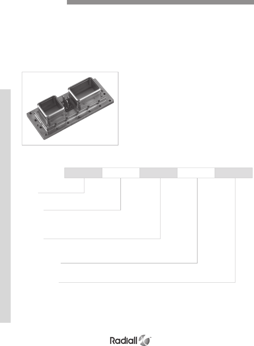
MPX 3 R 00 01
Series
MPX connector
Shell size
2 - 2 Cavities
3 - 4 Cavities
4 - 6 Cavities
Shell type
R - Receptacle shell
A - Plug shell
Modification code
Refer to page 5-21
Polarization code
Blank - Polarization device delivered unassembled
00 - Polarizing keys or posts are not delivered
Other - please refer to page 5-22
The MPX shells are machined from solid aluminium alloy and have a good conductive and high resistance
to corrosion thanks to cadmium yellow chromate plating.
There are 3 shell sizes which can respectively receive 2,4 and 6 inserts.
The plug shell is designed to be fitted with inserts for size 22 pin contacts and inserts for socket contacts
for all other contact sizes. The plug shell has a field replaceable EMI spring and a coupling seal on each
shell cavity and 3 polarization posts.
The receptacle shell is designed to be fitted with inserts for size 22 socket contacts and inserts for pin
contacts for the other contact sizes. The receptacle shell has 3 polarization keys.
Plug and receptacle can be either front or rear mounted.
Shell Information
HOW TO ORDER SHELLS
MPX SERIES
5-8
Our Most Important Connection is with You.™
Go online for data sheets & assembly instructions Visit www.radiall.com and enter the part number
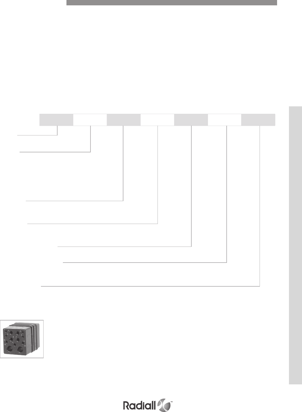
Inserts are made of the thermosetting resin, high grade thermoplastic or of aluminium alloy. They
have metallic retention clips to retain the contacts. Each insert has one polarization slot which has its
corresponding pin in each shell cavity.
Environmental inserts have:
A) a silicon rubber ring that ensures sealing between the insert and the shell.
B) a rear grommet which ensures sealing around each wire crimped on a contact.
C) an interfacial seal which ensures sealing around each protruding contact once the connector is matted.
Non environmental inserts do not include options "b" or "c."
All standardized inserts are for rear release, rear removable contacts, please refer to page 5-13 for front
release, front removable version.
MPX E 2 P 11T2 A S
Series
MPX series
Class (1)
E - Insert with interfacial seal, rear grommet
and o-ring
N - Insert with o-ring, without interfacial
seal and rear grommet
T - Insert with o-ring and interfacial
seal without rear grommet
Insert sze
1 – Insert for A, C and E shell cavities
2 – Insert for B, D and F shell cavities
Insert type
P - Insert for plug shell
R - insert for receptacle shell
Contact arrangement (2)
Refer to pages 5-14 to 5-21
Triax contact grounding (3)
Letter omitted - triax and quadrax contacts are grounded
A - triax contacts not grounded
Contact delivery
Letter omitted - insert is delivered without contacts
S - insert is delivered with crimp signal and power contacts (no coax, triax, twinax or quadrax contacts)
How to Order Insterts
HOW TO ORDER INSERTS
NOTES:
(1) E, N and T classes apply to inserts for rear release rear removable contacts
(2) Inserts 100 and 150 for front release front removable contacts are available, see page 5-13 for part numbers
(3) When A is omitted triax and quadrax contacts cavities are grounded to the shell
MPX SERIES
5-9
Our Most Important Connection is with You.™
Go online for data sheets & assembly instructions Visit www.radiall.com and enter the part number
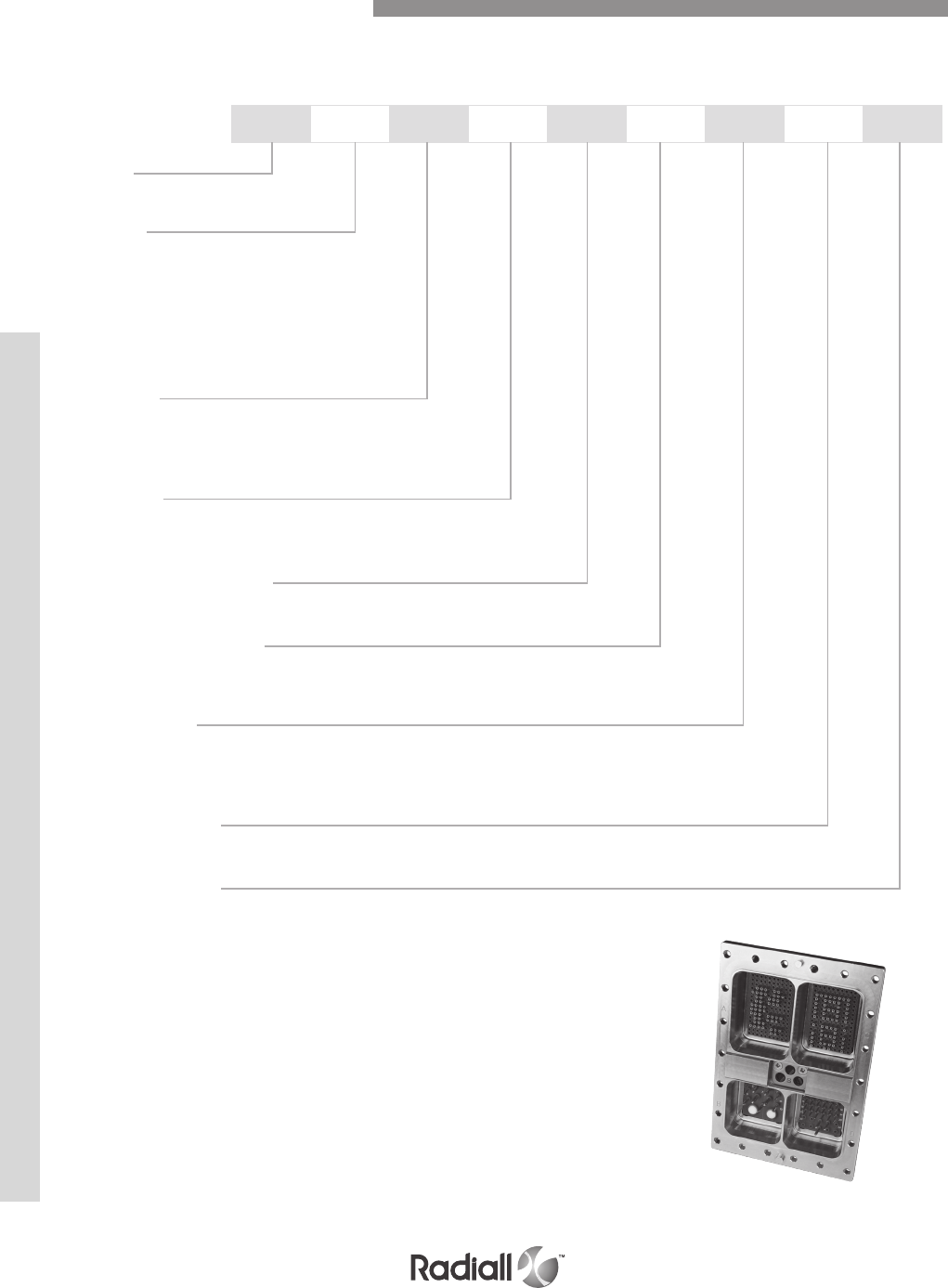
MPX E 2 R 202 A S 00 01
Series
MPX series
Class (1)
E - Insert with interfacial seal, rear grommet
and o-ring
N - Insert with o-ring, without interfacial
seal and rear grommet
T - Insert with o-ring and interfacial
seal without rear grommet
Shell Size
2 - 2 Cavities
3 - 4 Cavities
4 - 6 Cavities
Shell type
R - Receptacle shell
A - Plug shell
Insert combination code
Refer to pages 5-11 to 5-13
Triax contact grounding
Letter omitted - triax contacts are grounded
A - triax contacts not grounded
contact type (2)
X – Without contacts
S – Crimp contacts
Rear release PC-Tail : see page 5-23 to 5-32 and consult us for the PCB foot print
Modificaiton code
Refer to page 5-21
Polarization code
Blank - Polarization device delivered unassembled
00 - Polarizing keys or posts are not delivered
Other - please refer to page 5-22
HOW TO ORDER ASSEMBLED CONNECTORS
How to Order MPX Assembly Kit
NOTES:
(1) E, N and T classes apply to inserts for rear release rear removable contacts
(2) Coaxial, triaxial, twinax and quadrax contacts must be ordered separately
MPX SERIES
5-10
Our Most Important Connection is with You.™
Go online for data sheets & assembly instructions Visit www.radiall.com and enter the part number

DOD-STD-1842 CODES (USA)
STTEA CODES (EUROPE)
Insert Combination code
CODE SHELL SIZE Insert combination on shell
CAVITY A CAVITY B CAVITY C CAVITY D CAVITY E CAVITY F
001 2 47T2 100 / / / /
002 2 47T2 20T4 / / / /
003 2 47T2 34 / / / /
004 3 150 34 150 20T4 / /
005 3 150 100 47T2 100 / /
006 3 60 100 60 100 / /
007 3 150 100 150 100 / /
008 3 60 34 60 34 / /
009 4 150 34 150 20T4 150 20T4
010 4 24 34 150 100 150 20T4
011 4 150 34 150 20T4 150 T6
012 4 24 34 150 BLANK 150 20T4
CODE SHELL SIZE Insert combination on shell
CAVITY A CAVITY B CAVITY C CAVITY D CAVITY E CAVITY F
201 2 150 34 / / / /
202 3 150 20T4 BLANK 100 / /
203 2 126 100 / / / /
204 2 150 11C2 / / / /
205 3 150 T6 150 T6 / /
206 3 150 34 150 20T4 / /
207 2 150 20T4 / / / /
208 3 150 20T4 150 BLANK / /
209 2 47T2 11C2 / / / /
210 3 150 11C2 24 100 / /
211 2 150 11T2 / / / /
212 2 60 11T2 / / / /
213 3 24 34 24 20T4 / /
214 3 24 34 BLANK 20T4 / /
215 3 150 100 C12T6 11C2 / /
216 2 150 100 / / / /
217 2 24 11C2 / / / /
218 3 24 11C2 24 T6 / /
219 4 24 11C2 47T2 34 24 20T4
220 4 150 100 150 100 150 100
221 4 24 34 150 20T4 150 T6
222 3 150 11T2 24 100 / /
223 3 150 11C2 150 11C2 / /
224 2 150 62T2 / / / /
225 2 60 20T4 / / / /
226 3 150 34 150 100 / /
MPX SERIES
5-11
Our Most Important Connection is with You.™
Go online for data sheets & assembly instructions Visit www.radiall.com and enter the part number

STTEA CODES (EUROPE)
Insert Combination code
CODE SHELL SIZE Insert combination on shell
CAVITY A CAVITY B CAVITY C CAVITY D CAVITY E CAVITY F
227 3 150 20T4 24 BLANK / /
228 3 150 100 150 20T4 / /
229 3 150 20T4 24 11C2 / /
230 2 47T2 BLANK / / / /
231 2 24 BLANK / / / /
232 2 24 34 / / / /
233 3 150 34 150 34 / /
234 3 24 11C2 150 100 / /
235 3 150 BLANK 150 20T4 / /
236 4 24 34 24 BLANK 150 20T4
237 2 24 100 / / / /
238 3 BLANK 11C2 BLANK 20T4 / /
239 3 24 34 24 34 / /
240 3 47T2 34 24 34 / /
241 4 24 34 24 34 24 34
242 3 BLANK 11C2 BLANK 34 / /
243 3 60 34 24 34 / /
244 4 60 34 60 34 24 34
245 3 150 11C2 24 11C2 / /
246 4 24 34 60 100 150 20T4
247 4 24 34 24 100 150 20T4
248 4 60 T6 60 T6 24 T6
249 4 60 T6 BLANK T6 150 T6
250 3 24 BLANK 150 20T4 / /
251 3 126 34 126 20T4 / /
252 3 150 34 BLANK 11C2 / /
253 3 24 100 150 20T4 / /
254 3 150 62T2 150 62T2 / /
255 3 150 11C2 BLANK 34 / /
256 2 60 11C2 / / / /
257 3 150 100 C12T6 34 / /
258 3 150 11C2 150 34 / /
259 4 150 20T4 24 T6 150 11T2
260 3 150 T6 150 34 / /
261 3 150 11C2 126 34 / /
262 3 150 100 150 62T2 / /
263 2 60 34 / / / /
264 3 150 T6 150 100 / /
265 3 C12T6 11C2 150 100 / /
266 2 47T2 11T2 / / / /
267 4 150 34 150 100 150 34
269 2 126 11T2 / / / /
270 3 150 11T2 150 20T4 / /
271 3 150 11T2 150 11T2 / /
272 4 150 34 150 100 150 20T4
MPX SERIES
5-12
Our Most Important Connection is with You.™
Go online for data sheets & assembly instructions Visit www.radiall.com and enter the part number

STTEA CODES (EUROPE)
CONTACT ARRANGEMENTS FOR FRONT RELEASE FRONT REMOVABLE CONTACTS
These inserts are available for receptacle shell only and are designed to be fitted with front release front
removable size 22 pc tail contacts and thus do not have rear grommets. Socket insert mating side shown.
These inserts are not normalized.
618500061
618500081
Insert Combination code
Inserts Layouts Front Release Front Removable
CODE SHELL SIZE Insert combination on shell
CAVITY A CAVITY B CAVITY C CAVITY D CAVITY E CAVITY F
273 4 126 100 150 100 126 100
274 3 C12T6 11C2 BLANK 100 / /
275 3 150 T6 150 BLANK / /
276 2 150 T6 / / / /
277 3 C12T6 34 60 34 / /
278 3 150 20T4 150 20T4 / /
279 3 60 20T4 60 20T4 / /
280 4 150 100 150 100 150 62T2
281 3 150 11C2 150 100 / /
282 3 150 11T2 150 100 / /
283 3 BLANK 20T4 150 20T4 / /
284 3 150 20T4 150 100 / /
285 3 150 20T4 150 11C2 / /
286 3 126 T6 150 20T4 / /
287 3 150 11C2 150 20T4 / /
Number of contacts Contact size Location
150 22 1 to 150
Number of contacts Contact size Location
100 22 1 to 100
MPX SERIES
5-13
Our Most Important Connection is with You.™
Go online for data sheets & assembly instructions Visit www.radiall.com and enter the part number
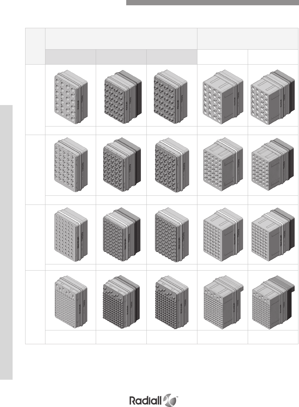
Insert
name
EQUIPMENT SIDE
RECEPTACLE SHELL
AVIONIC SIDE
PLUG SHELL
Version N Version E Version T Version N Version E
24 (A)
24x #12 RR/RR 24x #12 RR/RR 24x #12 RR/RR 24x #12 RR/RR 24x #12 RR/RR
35 (A)
35x #16 RR/RR 35x #16 RR/RR 35x #16 RR/RR 35x #16 RR/RR 35x #16 RR/RR
60 (A)
60x #20 RR/RR 60x #20 RR/RR 60x #20 RR/RR 60x #20 RR/RR 60x #20 RR/RR
126 (A)
120x #22 RR/RR
6x #16 RR/RR
120x #22 RR/RR
6x #16 RR/RR
120x #22 RR/RR
6x #16 RR/RR
120x #22 RR/RR
6x #16 RR/RR
120x #22 RR/RR
6x #16 RR/RR
Insert Layout for Cavities A, C, or E
The symbol A represents that the insert is available in a non-grounded version
(see page 5-9 for triax contact grounding)
MPX SERIES
5-14
Our Most Important Connection is with You.™
Go online for data sheets & assembly instructions Visit www.radiall.com and enter the part number
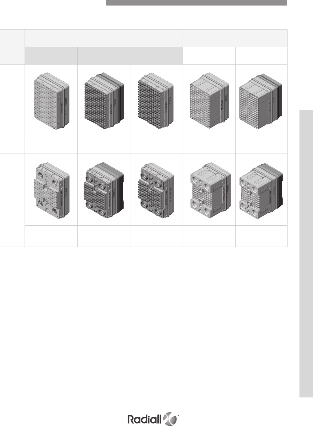
Insert
name
EQUIPMENT SIDE
RECEPTACLE SHELL
AVIONIC SIDE
PLUG SHELL
Version N Version E Version T Version N Version E
150 (A)
150x #22 RR/RR 150x #22 RR/RR 150x #22 RR/RR 150x #22 RR/RR 150x #22 RR/RR
68Q4 (A)
62x #22 RR/RR
6x #16 RR/RR
4x #8 RR/RR
62x #22 RR/RR
6x #16 RR/RR
4x #8 RR/RR
62x #22 RR/RR
6x #16 RR/RR
4x #8 RR/RR
62x #22 RR/RR
6x #16 RR/RR
4x #8 RR/RR
62x #22 RR/RR
6x #16 RR/RR
4x #8 RR/RR
The symbol A represents that the insert is available in a non-grounded version
(see page 5-9 for triax contact grounding)
Insert Layout for Cavities A, C, or E
MPX SERIES
5-15
Our Most Important Connection is with You.™
Go online for data sheets & assembly instructions Visit www.radiall.com and enter the part number
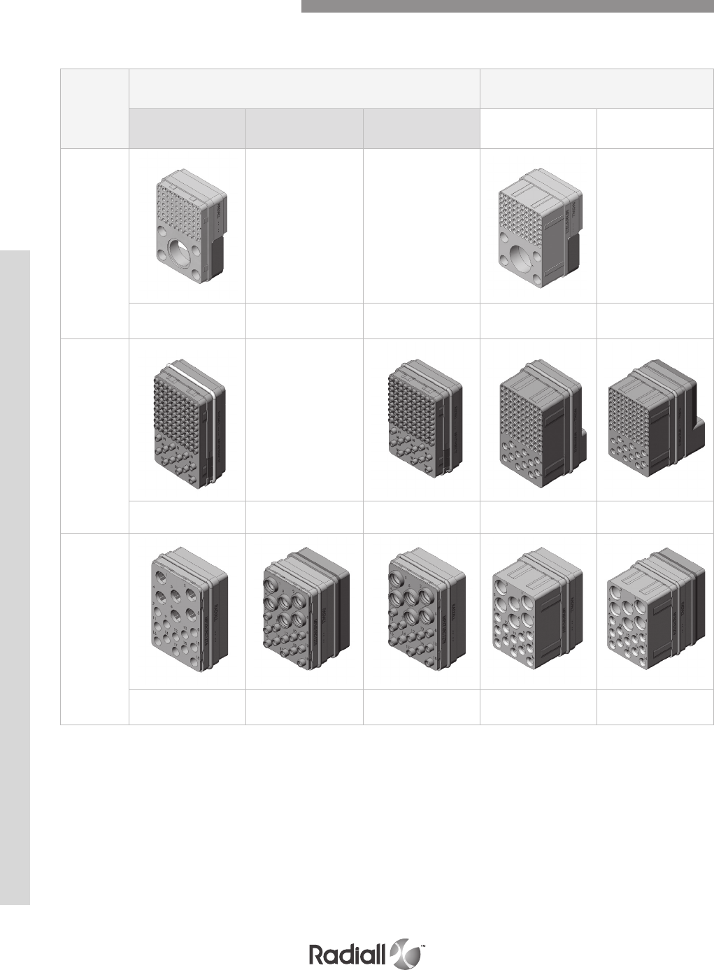
Insert
name
EQUIPMENT SIDE
RECEPTACLE SHELL
AVIONIC SIDE
PLUG SHELL
Version N Version E Version T Version N Version E
70C1 (A)
Not available Not available Not available
70x #22 RR/RR
1x #1 FR/RR 70x #22 RR/RR
1x #1 FR/RR
90C12 (A)
Not available
90x #22 RR/RR12x #16
RR/RR 90x #22 RR/RR12x #16
RR/RR
90x #22 RR/RR12x #16
RR/RR
90x #22 RR/RR12x #16
RR/RR
C12T6
(metallic
insert)
12x #12 RR/RR
6x #8 RR/RR
12x #12 RR/RR
6x #8 RR/RR
12x #12 RR/RR
6x #8 RR/RR
12x #12 RR/RR
6x #8 RR/RR
12x #12 RR/RR
6x #8 RR/RR
The symbol A represents that the insert is available in a non-grounded version
(see page 5-9 for triax contact grounding)
Insert Layout for Cavities A, C, or E
MPX SERIES
5-16
Our Most Important Connection is with You.™
Go online for data sheets & assembly instructions Visit www.radiall.com and enter the part number
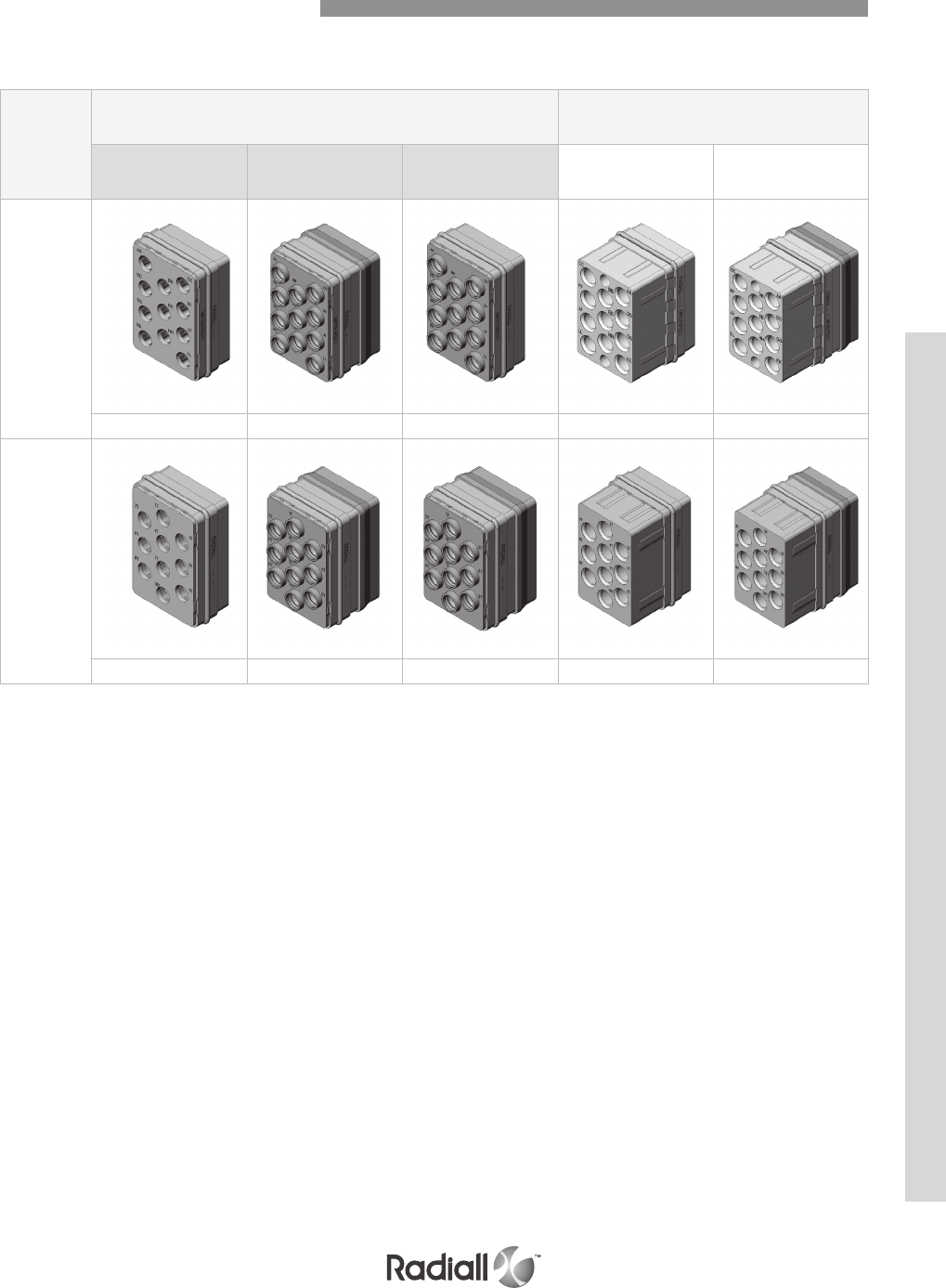
Insert
name
EQUIPMENT SIDE
RECEPTACLE SHELL
AVIONIC SIDE
PLUG SHELL
Version N Version E Version T Version N Version E
Q11
(metallic
insert)
11x #8 RR/RR 11x #8 RR/RR 11x #8 RR/RR 11x #8 RR/RR 11x #8 RR/RR
T10
(metallic
insert)
10x #8 RR/RR 10x #8 RR/RR 10x #8 RR/RR 10x #8 RR/RR 10x #8 RR/RR
The symbol A represents that the insert is available in a non-grounded version
(see page 5-9 for triax contact grounding)
Insert Layout for Cavities A, C, or E
MPX SERIES
5-17
Our Most Important Connection is with You.™
Go online for data sheets & assembly instructions Visit www.radiall.com and enter the part number
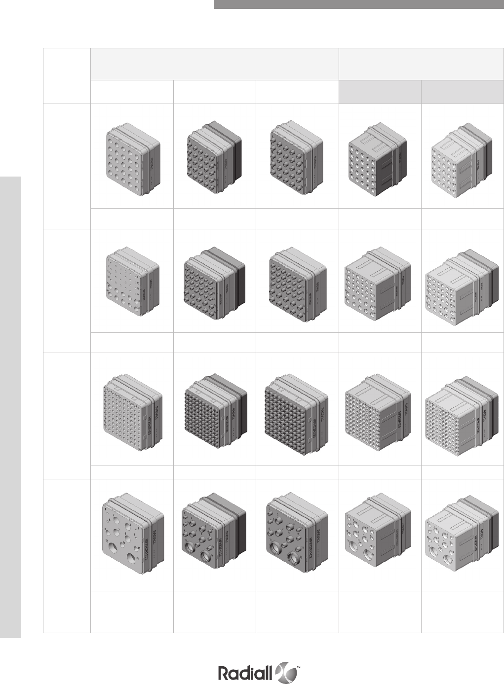
Insert
name
EQUIPMENT SIDE
RECEPTACLE SHELL
AVIONIC SIDE
PLUG SHELL
Version N Version E Version T Version N Version E
25 (A)
25x #16 RR/RR 25x #16 RR/RR 25x #16 RR/RR 25x #16 RR/RR 25x #16 RR/RR
34 (A)
24x #20 RR/RR
10x #16 RR/RR
24x #20 RR/RR
10x #16 RR/RR
24x #20 RR/RR
10x #16 RR/RR
24x #20 RR/RR
10x #16 RR/RR
24x #20 RR/RR
10x #16 RR/RR
100 (A)
100x #22 RR/RR 100x #22 RR/RR 100x #22 RR/RR 100x #22 RR/RR 100x #22 RR/RR
11C2 (A)
4x #20 RR/RR
3x #16 RR/RR
4x #12 RR/RR
2x #5 RR/RR
4x #20 RR/RR
3x #16 RR/RR
4x #12 RR/RR
2x #5 RR/RR
4x #20 RR/RR
3x #16 RR/RR
4x #12 RR/RR
2x #5 RR/RR
4x #20 RR/RR
3x #16 RR/RR
4x #12 RR/RR
2x #5 RR/RR
4x #20 RR/RR
3x #16 RR/RR
4x #12 RR/RR
2x #5 RR/RR
The symbol A represents that the insert is available in a non-grounded version
(see page 5-9 for triax contact grounding)
Insert Layout for Cavities B, D, or F
MPX SERIES
5-18
Our Most Important Connection is with You.™
Go online for data sheets & assembly instructions Visit www.radiall.com and enter the part number
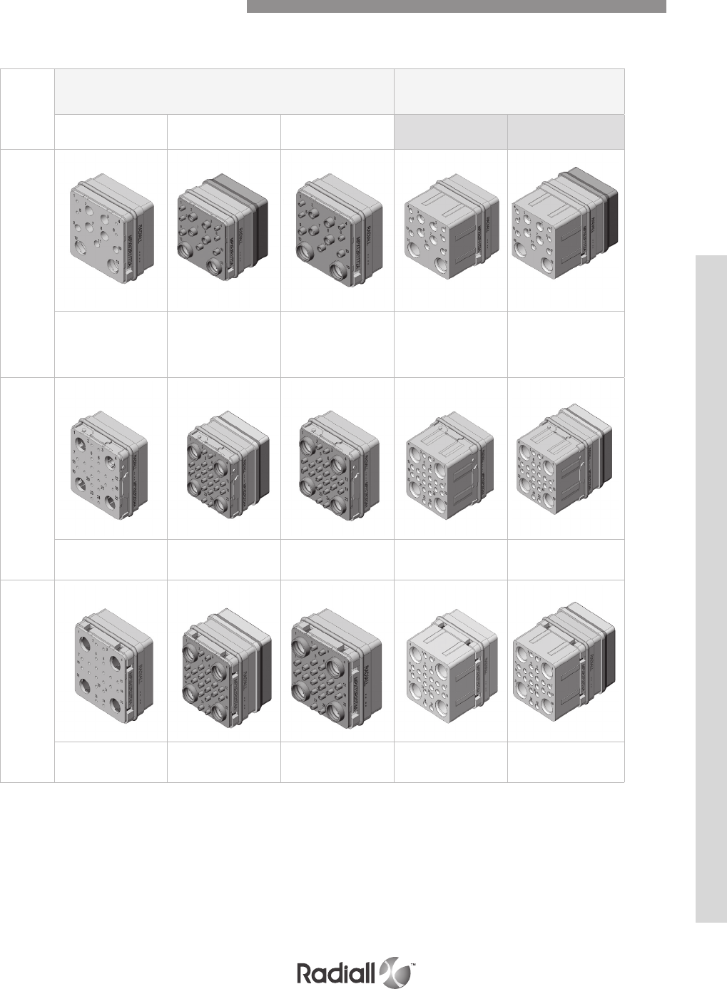
Insert
name
EQUIPMENT SIDE
RECEPTACLE SHELL
AVIONIC SIDE
PLUG SHELL
Version N Version E Version T Version N Version E
11T2 (A)
4x #20 RR/RR
3x #16 RR/RR
2x #8 RR/RR
4x #12 RR/RR
4x #20 RR/RR
3x #16 RR/RR
2x #8 RR/RR
4x #12 RR/RR
4x #20 RR/RR
3x #16 RR/RR
2x #8 RR/RR
4x #12 RR/RR
4x #20 RR/RR
3x #16 RR/RR
2x #8 RR/RR
4x #12 RR/RR
4x #20 RR/RR
3x #16 RR/RR
2x #8 RR/RR
4x #12 RR/RR
20Q4 (A)
20x #20 RR/RR
4x #8
Quadrax RR/RR
20x #20 RR/RR
4x #8
Quadrax RR/RR
20x #20 RR/RR
4x #8
Quadrax RR/RR
20x #20 RR/RR
4x #8
Quadrax RR/RR
20x #20 RR/RR
4x #8
Quadrax RR/RR
20T4 (A)
20x #20 RR/RR
4x #8 RR/RR
20x #20 RR/RR
4x #8 RR/RR
20x #20 RR/RR
4x #8 RR/RR
20x #20 RR/RR
4x #8 RR/RR
20x #20 RR/RR
4x #8 RR/RR
The symbol A represents that the insert is available in a non-grounded version
(see page 5-9 for triax contact grounding)
Insert Layout for Cavities B, D, or F
MPX SERIES
5-19
Our Most Important Connection is with You.™
Go online for data sheets & assembly instructions Visit www.radiall.com and enter the part number
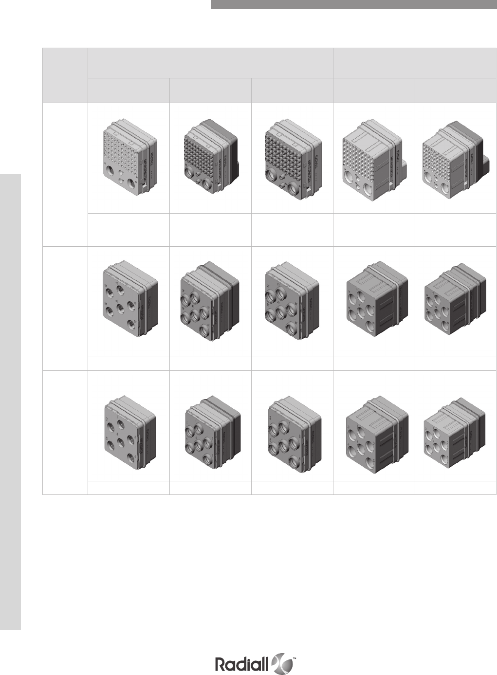
Insert
name
EQUIPMENT SIDE
RECEPTACLE SHELL
AVIONIC SIDE
PLUG SHELL
Version N Version E Version T Version N Version E
62T2 (A)
60x #22 RR/RR
2x #16 RR/RR
2x #8 RR/RR
60x #22 RR/RR
2x #16 RR/RR
2x #8 RR/RR
60x #22 RR/RR
2x #16 RR/RR
2x #8 RR/RR
60x #22 RR/RR
2x #16 RR/RR
2x #8 RR/RR
60x #22 RR/RR
2x #16 RR/RR
2x #8 RR/RR
Q6
(metallic
insert)
6x #8 RR/RR 6x #8 RR/RR 6x #8 RR/RR 6x #8 RR/RR 6x #8 RR/RR
T6
(metallic
insert)
6x #8 RR/RR 6x #8 RR/RR 6x #8 RR/RR 6x #8 RR/RR 6x #8 RR/RR
The symbol A represents that the insert is available in a non-grounded version
(see page 5-9 for triax contact grounding)
Insert Layout for Cavities B, D, or F
MPX SERIES
5-20
Our Most Important Connection is with You.™
Go online for data sheets & assembly instructions Visit www.radiall.com and enter the part number
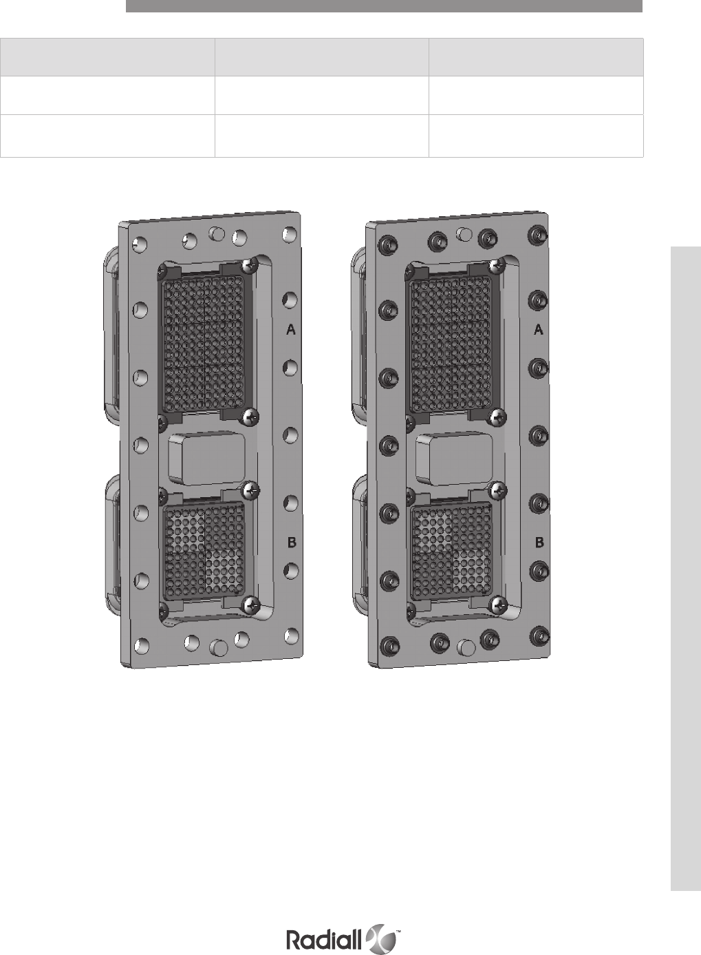
CODE 10CODE 00
Modifcation Code
Code Receptacle Shell Plug Shell
00 Sizes 2,3 & 4 :
All holes Ø .150 inch (3.80 mm)
Sizes 2,3 & 4 :
All holes Ø .150 inch (3.80 mm)
10
Sizes 2,3 & 4:
All holes fitted with M3 x 0.02 inch
(0.50 mm) clinch-nuts
Sizes 2,3 & 4:
All holes fitted with M3 x 0.02 inch
(0.50 mm) clinch-nuts
MPX SERIES
5-21
Our Most Important Connection is with You.™
Go online for data sheets & assembly instructions Visit www.radiall.com and enter the part number
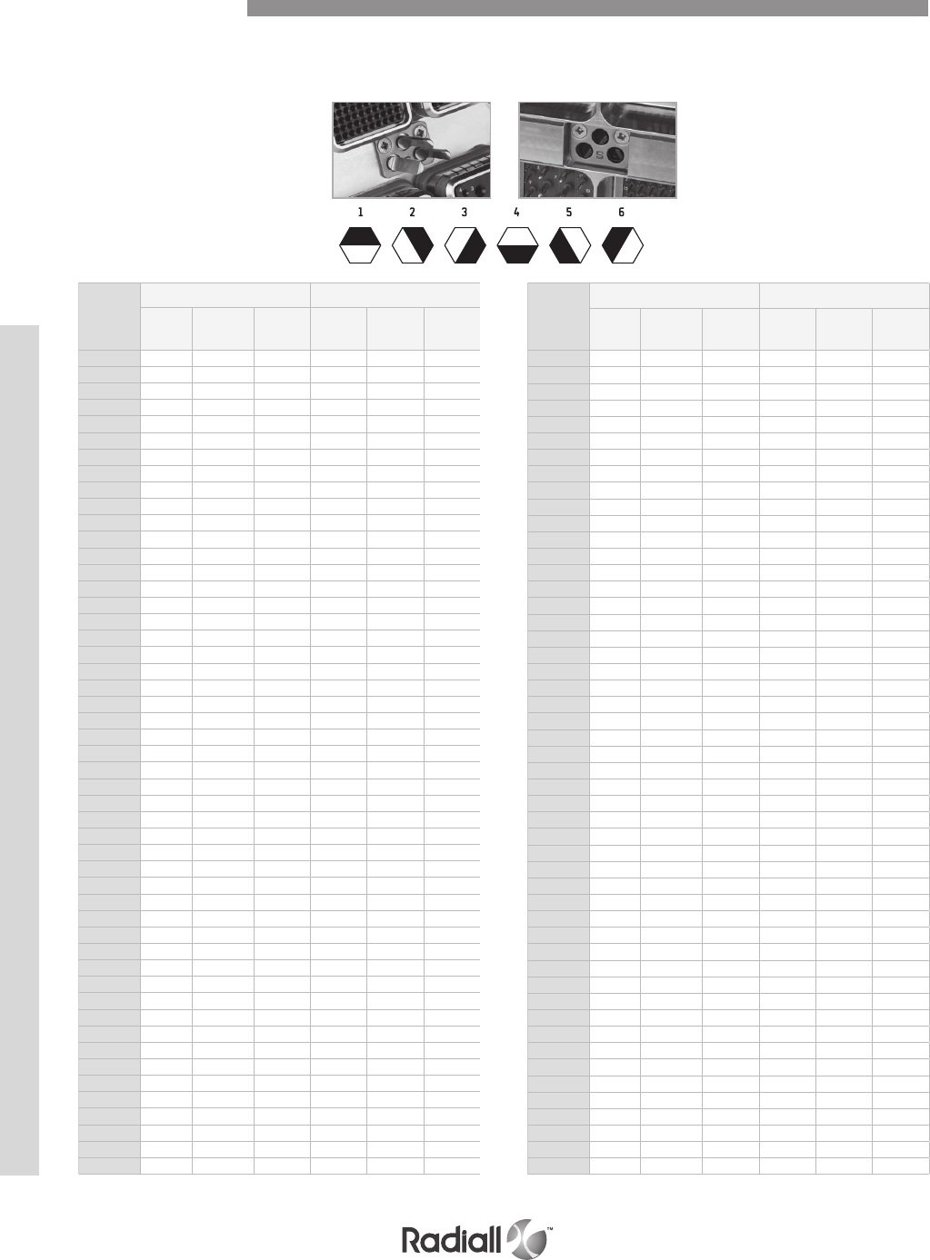
POSITION OF POLARIZATION KEYS AND POSTS
Connectors are shown front side and with cavity A upwards.
Code
number
Receptacle shell Plug shell
Le
key
Center
key
Right
key
Le
post
Center
post
Right
post
00 / / / / / /
01 4 4 4 1 1 1
02 4 4 3 2 1 1
03 4 4 2 3 1 1
04 4 4 1 4 1 1
05 4 4 6 5 1 1
06 4 4 5 6 1 1
07 5 4 4 1 1 6
08 5 4 3 2 1 6
09 5 4 2 3 1 6
10 5 4 1 4 1 6
11 5 4 6 5 1 6
12 5 4 5 6 1 6
13 6 4 4 1 1 5
14 6 4 3 2 1 5
15 6 4 2 3 1 5
16 6 4 1 4 1 5
17 6 4 6 5 1 5
18 6 4 5 6 1 5
19 1 4 4 1 1 4
20 1 4 2 2 1 4
21 1 4 2 3 1 4
22 1 4 1 4 1 4
23 1 4 6 5 1 4
24 1 4 5 6 1 4
25 2 4 4 1 1 3
26 2 4 3 2 1 3
27 2 4 2 3 1 3
28 2 4 1 4 1 3
29 2 4 6 5 1 3
30 2 4 5 6 1 3
31 3 4 4 1 1 2
32 3 4 3 2 1 2
33 3 4 2 3 1 2
34 3 4 1 4 1 2
35 3 4 6 5 1 2
36 3 4 5 6 1 2
37 4 3 4 1 2 1
38 4 3 3 2 2 1
39 4 3 2 3 2 1
40 4 3 1 4 2 1
41 4 3 6 5 2 1
42 4 3 5 6 2 1
43 5 3 4 1 2 6
44 5 3 3 2 2 6
45 5 3 2 3 2 6
46 5 3 1 4 2 6
47 5 3 6 5 2 6
48 5 3 5 6 2 6
49 6 3 4 1 2 5
Code
number
Receptacle shell Plug shell
Le
key
Center
key
Right
key
Le
post
Center
post
Right
post
50 6 3 3 2 2 5
51 6 3 2 3 2 5
52 6 3 1 4 2 5
53 6 3 6 5 2 5
54 6 3 5 6 2 5
55 1 3 4 1 2 4
56 1 3 3 2 2 4
57 1 3 2 3 2 4
58 1 3 1 4 2 4
59 1 3 6 5 2 4
60 1 3 5 6 2 4
61 2 3 4 1 2 3
62 2 3 3 2 2 3
63 2 3 2 3 2 3
64 2 3 1 4 2 3
65 2 3 6 5 2 3
66 2 3 5 6 2 3
67 3 3 4 1 2 2
68 3 3 3 2 2 2
69 3 3 2 3 2 2
70 3 3 1 4 2 2
71 3 3 6 5 2 2
72 3 3 5 6 2 2
73 4 2 4 1 3 1
74 4 2 3 2 3 1
75 4 2 2 3 3 1
76 4 2 1 4 3 1
77 4 2 6 5 3 1
78 4 2 5 6 3 1
79 5 2 4 1 3 6
80 5 2 3 2 3 6
81 5 2 2 3 3 6
82 5 2 1 4 3 6
83 5 2 6 5 3 6
84 5 2 5 6 3 6
85 6 2 4 1 3 5
86 6 2 3 2 3 5
87 6 2 2 3 3 5
88 6 2 1 4 3 5
89 6 2 6 5 3 5
90 6 2 5 6 3 5
91 1 2 4 1 3 4
92 1 2 3 2 3 4
93 1 2 2 3 3 4
94 1 2 1 4 3 4
95 1 2 6 5 3 4
96 1 2 5 6 3 4
97 2 2 4 1 3 3
98 2 2 3 2 3 3
99 2 2 2 3 3 3
Dark area represents
the polarizing post
Clear portion represents
the key hole
Polarization Code
POSITION CODINGS
MPX SERIES
5-22
Our Most Important Connection is with You.™
Go online for data sheets & assembly instructions Visit www.radiall.com and enter the part number
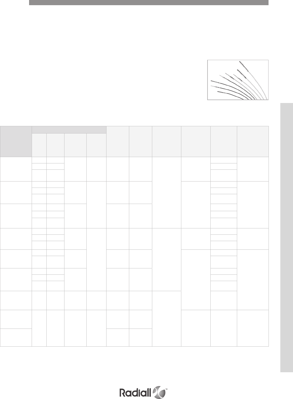
The MPX series contacts are offered in crimp and pc tail termination. Pin contacts are installed in the receptacle
shell and socket contacts in the plug shell except size 22 contacts for which pin contacts are installed in the
plug shell and socket contacts in the receptacle shell.
Size 22 contacts in pc tail termination are offered in both rear release rear removable and front release front
removable style. All the other sizes of contacts are offered in the rear release rear removable style only. The
contacts are installed and removed using normalized MILI81969 tooling. They also have low insertion and
extraction force.
Following is the contacts range available in types and sizes.
- Size 22 signal contacts
- Sizes 20, 16 and 12 power contacts
- Sizes 12, 16, 5 and 8 coaxial contacts
- Size 8 twinax contacts for shielded twisted pairs
- Size 8 quadrax contacts
Notes
(1) DANIELS WA27-309-EP air pressure tool with crimp setting 5 can also be used
Crimp setting 5 is not adjustable and must be set by the factory
(2) Contacts size 22,20,16 and 12 are M39029/94 & M39029/93 or EN3155/026 & EN3155/027 design
Contacts
SIGNAL AND POWER CRIMP CONTACTS
Release Rear Removable
Contact size (2)
Wire
Pin p/n Socket p/n
Crimping tool
Radiall p/n
(MIL p/n)
Positioner p/n Selector p/n Ins/ext
tool p/n
AWG
Cross
section
(mm²)
Wire
Outside dia.
Inch (mm)
Stripping
length
inch (mm)
26 0.14 .030 (0.76)
to
.052
(1.32)
.137
(3.5) 618200 618300
282281
(M22520/2-01)
282970
(M22520/2-23)
3
282885
(M81969/1-01)
24 0.21 3
22 0.38 4
20
reduced crimp
barrel
26 0.14 .030 (0.76)
to
.052 (1.32) .157
(4.0)
/ 618311
282971
(M22520/2-08)
3
282549029
(M81969/14-10)
24 0.21 3
22 0.38 4
20
24 0.21 .035 (0.89)
to
.060 (1.52)
618210 618310
5
22 0.38 6
20 0.60 7
16
20 0.60 .048 (1.21)
to
.080 (2.03)
.236 (6.0)
618230 618330
282291
(M22520/1-01)
282972
(M22520/1-02)
4
282515
(M81969/14-03)
18 0.93 5
16 1.34 6
12
14 3.18 .091 (2.31)
to
.114 (2.90)
618240 618340
282579
(M22520/1-11)
7
282549004
(M81969/14-04)
12 1.91 8
12
reduced crimp
barrel
20 0.60 .048 (1.21)
to 080
(2.03)
/ 618341
4
18 0.93 5
16 1.34 6
12
enlarged
crimp barrel
10 5.0 .234 (5.70) .354 (9.0) / 618342
282296
(DANIELS
M300 BT) (1)
1
8
non
environmental 10
5.0 .234 (5.70) .354 (9.0)
618270 618370 282586
6282549001
(M81969/28-03)
8
environmental
618270001 618370001
MPX SERIES
5-23
Our Most Important Connection is with You.™
Go online for data sheets & assembly instructions Visit www.radiall.com and enter the part number
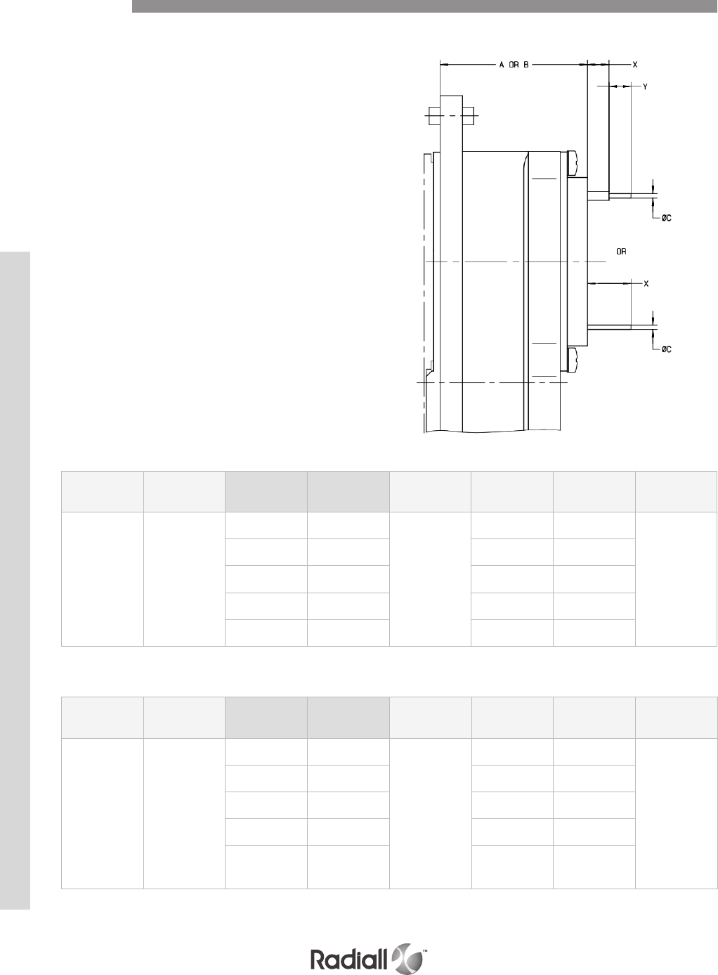
SIGNAL AND POWER PC TAIL CONTACTS
Release Rear Removable
For details on A & B dimensions
refer to page 5-35
GOLD PC TAIL CONTACTS
PRE-TINNED PC TAIL CONTACTS
Contacts
Contact size Contact
arrangement Pin Socket Ext. tool
X
inch (mm)
Y
inch (mm)
C
inch (mm)
22 618500061 &
618500081
/ 618304001
282500
.163/.191
(4.15/4.85)
.173/.181
(4.40/4.60)
.024/.027
(0.60/0.70)
/ 618304002 .085/.112
(2.15/2.85)
.232/.240
(5.90/6.10)
/ 618360 .150/.180
(3.80/4.60) N/A
/ 618361 .252/.283
(6.40/7.20) N/A
/ 618362 .374/.405
(9.50/10.3) N/A
Contact size Contact
arrangement Pin Socket Ext. tool
X
inch (mm)
Y
inch (mm)
C
inch (mm)
22 618500061 &
618500081
/ 618304003
282500
.163/.191
(4.15/4.85)
.173/.201
(4.40/5.10)
.031
(0.80) max
/ 618304004 .085/.112
(2.15/2.85)
.232/.260
(5.90/6.60)
/ 618360001 .150/.201
(3.80/5.10) N/A
/ 618361001 .252/.303
(6.40/7.70) N/A
/ 618362001 .374/.425
(9.50/10.80) N/A
MPX SERIES
5-24
Our Most Important Connection is with You.™
Go online for data sheets & assembly instructions Visit www.radiall.com and enter the part number
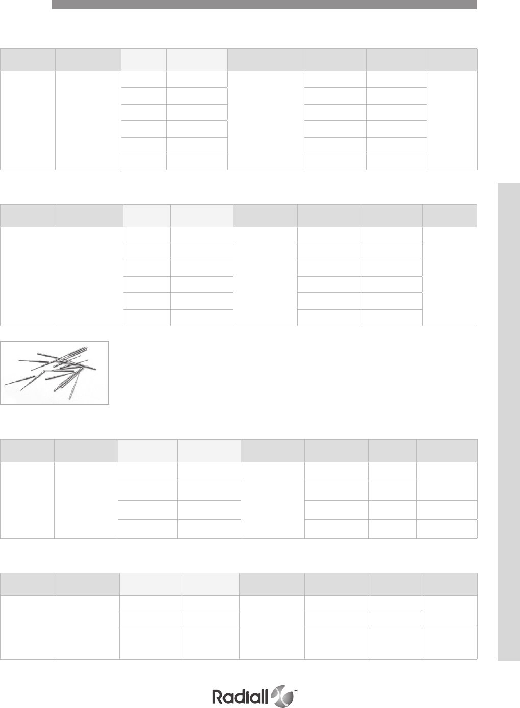
SIGNAL AND POWER PC TAIL CONTACTS Rear Release Rear Removable
Contacts
GOLD PC TAIL CONTACTS
Contact size Contact
arrangement Pin Socket Ext. tool X
inch (mm)
Y
inch (mm)
C
inch (mm)
22
150
126
70C12
100
62T2
/ 618302 282885
(M81969/1-01)
or
282522
(M81969/14-01)
.059/.087
(1.50/2.20)
.145/.154
(3.70/3.90)
.024/.027
(0.60/0.70)
/ 618303001 .209/.248
(5.30/6.30) N/A
/ 618303002 .391/.431
(9.95/10.95) N/A
/ 618303003 .138/.177
(3.50/4.50) N/A
/ 618303004 .150/.169
(3.80/4.30)
.145/.154
(3.70/3.90)
/ 618303005 .303/.343
(7.70/8.70) N/A
PRE-TINNED PC TAIL CONTACTS
Contact size Contact
arrangement Pin Socket Ext. tool X
inch (mm)
Y
inch (mm)
C
inch (mm)
22
150
126
70C12
100
62T2
/ 618302001 2282885
(M81969/1-01)
or
282522
(M81969/14-01)
.059/.107
(1.50/2.70)
.145/.174
(3.70/4.40)
.031
(0.80) max
/ 618303007 .209/.268
(5.30/6.80) N/A
/ 618303008 .391/.451
(9.95/14.45) N/A
/ 618303009 .138/.197
(3.50/5.00) N/A
/ 618303010 .150/.189
(3.80/4.80)
.145/.174
(3.70/4.40)
/ 618303011 .303/.363
(7.70/9.20) N/A
GOLD PC TAIL CONTACTS
Contact size Contact
arrangement Pin Socket Ext. tool X
inch (mm)
Y
inch (mm)
C
inch (mm)
20
11T2
11C2
34, 60
47T2
20T4
618213001 / 282886
(M81969/1-02)
or
282549029
(M81969/14-02)
.281/.321
(7.15/8.15) N/A .037/.040
(0.95/1.01)
618213002 / .137/.177
(3.50/4.50) N/A
618231005 / .517/.557
(13.15/14.15) N/A .032/.034
(0.81/0.86)
/ 618316001 .391/.431
(9.95/10.95) N/A .024/.027
(0.60/0.70)
PRE-TINNED PC TAIL CONTACTS
Contact size Contact
arrangement Pin Socket Ext. tool X
inch (mm)
Y
inch (mm)
C
inch (mm)
20
11T2
11C2
34, 60
47T2
20T4
618213006 / 282886
(M81969/1-02)
or
282549029
(M81969/14-02)
.281/.341
(7.15/8.65) N/A .045
(1.15) max
618213007 / .137/.197
(3.50/5.00) N/A
618231008 / .517/.577
(13.15/14.65) N/A .037
(0.95) max
MPX SERIES
5-25
Our Most Important Connection is with You.™
Go online for data sheets & assembly instructions Visit www.radiall.com and enter the part number
SIGNAL AND POWER PC TAIL CONTACTS Rear Release Rear Removable
Contacts
GOLD PC TAIL CONTACTS
PRE-TINNED PC TAIL CONTACTS
Contact size Contact arrangement Pin Socket Ext. tool X
inch (mm)
Y
inch (mm)
C
inch (mm)
16
62T2
11C2
11T2
25, 34
35, 126
618233001 / 282546
(M81969/1-03)
or
282515
(M81969/14-03)
.281/.321
(7.15/8.15) N/A
.057/.061
(1.45/1.55)618233002 / .370/.409
(9.40/10.40) N/A
618233003 / .137/.177
(3.50/4.50) N/A
GOLD PC TAIL CONTACTS
Contact size Contact arrangement Pin Socket Ext. tool X
inch (mm)
Y
inch (mm)
C
inch (mm)
12
11C2
11T2, 6T4
24, C12T6
70C12
618243001 / 282547
(M81969/28-02)
or
282549004
(M81969/14-04)
.281/.321
(7.15/8.15) N/A .076/.080
(1.95/2.05)618243002 / .137/.177
(3.50/4.50) N/A
618243003 / .076/.120
(1.95/3.05) N/A
PRE-TINNED PC TAIL CONTACTS
Contact size Contact arrangement Pin Socket Ext. tool X
inch (mm)
Y
inch (mm)
C
inch (mm)
12
11C2
11T2, 6T4
24, C12T6
70C12
618243001 / 282547
(M81969/28-02)
or
282549004
(M81969/14-04)
.281/.321
(7.15/8.15) N/A
.076/.080
(1.95/2.05)618243002 / .137/.177
(3.50/4.50) N/A
618243003 / .076/.120
(1.95/3.05) N/A
MPX SERIES
5-26
Our Most Important Connection is with You.™
Go online for data sheets & assembly instructions Visit www.radiall.com and enter the part number
COAXIAL CRIMP CONTACTS Rear Release Rear Removable
Contacts
DESIGN AS PER EN3155-030 & 031 / M39029/73 & 74
DESIGN AS PER EN3155-028 & 029
Ins/ext tool: 282546 (M81696/1-03)
Contact
size Contact
arrangement Cable Pin Socket
Center contact Outer body
Crimping tool Positioner
tool Sel Crimping tool Positioner
tool Sel
16
126
62T2
11C2
11T2
34
25
35
RG179
RG316
KX22DS
ASNE0752WS
ASNE0632WK
618150 618050
282281
(M22520/2-01) 282555
4
282292
(M22520/4-01) 282556 /
ASNE0639XY 1
F1703-134
AXON
P813859 & P822817
ASNE0690WL
618151 618051
2
KX21DS / 618053
RG178
KX21 618154 618054
ASNE0633WG 1
Contact
size (2) Contact
arrangement Cable Pin Socket
Center contact Outer body
Crimping tool Positioner
tool Sel Crimping tool Positioner
tool Sel
12
11C2
11T2
24
6T4
C12T6
70C12
RG179
RG316
ASNE0639XY
618140 618040
282281
(M22520/2-01) 282580
4
282297
(M22520/31-01) 282581 /
ASNE0690WL 618140003 618040003 3
BUS 3910
AXON
P503031
618141 618041 5
ASNE0633WG
RG178
KX21
618142 618042 4
Contact
size Contact
arrangement Cable Pin Socket
Center contact Outer body
Crimping tool Positioner tool Sel Crimping tool Positioner tool
5 11C2
RG58
KX15 618120 (1) 618020 (1)
282281
(M22520/2-01) 282550
6
282293
(M22520/5-01)
282246
(M22520/5-05
hex A)
RG141
ASNE0293XF 8
282246
(M22520/5-05
hex B)
RG142
RG223 / 618021001 8
RG400 6
ASNE0691WM 618124001 618024001 8
ASNE0639XY
RG179
RG187
618123 (1) 618023 (1) 7
Contact
size Contact
arrangement Cable Pin Socket
Center contact Outer body
Crimping tool Positioner tool Sel Crimping tool Positioner tool
8
62T220T4
11T2
T6
47T2
C12T6
6T4
RG58
KX15
RG316
RG141
/ 618030 (1)
282281
(M22520/2-01) 282572
6
282293
(M22520/5-01)
282236
(M22520/5-45
hex A)
7
8
KX22
RG316
RG174
/ 618032 (1) 7
RG400 / 618033 (1) 8
ASNE0691WM 618135 618035 (1) solder
Ins/Ext tool: 282549001 (M81969/28-03)
Non environmental size 8 pin contacts are delivered with an alignment boot (p/n: 618920) to reduce the play at the contact extremity.
A RADIALL DESIGN
Ins/Ext tool: 282946 (M81969/28-01)
DESIGN AS PER EN3155-032 & 033 M39029/99 & 100
Ins/ext tool: 282547 (M81696/28-02)
MPX SERIES
5-27
Our Most Important Connection is with You.™
Go online for data sheets & assembly instructions Visit www.radiall.com and enter the part number
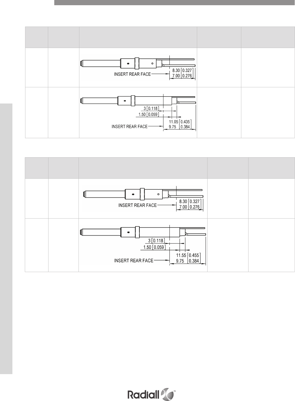
NOTES:
(1) Contacts Ins/ext tool: 282546 (M81969/1-03)
(2) For PC drill patern please contact Radiall
SIZE 16 PRE-TINNED PC TAIL
PC TAIL COAX CONTACTS Rear Release Rear Removable
Contacts
SIZE 16 PC TAIL mating interface as per EN3155-028 & 029
Contact
type Part number (1) Contact drawing (2)
Rear extension from
all insert
inch (mm)
Rear extension from
126 & 62T2 inserts only
inch (mm)
Pin 618153
.275 / .327
(7.00 / 8.30)
.297 / .349
(7.55 / 8.85).
Pin 618153001
.383 / .435
(9.75 / 11.05)
.405 / .457
(10.30 / 11.60).
Contact
type Part number (1) Contact drawing (2)
Rear extension from
all insert
inch (mm)
Rear extension from 126
& 62T2 inserts only
inch (mm)
Pin 618153002
.275 / .346
(7.00 / 8.80)
.297 / .368
(7.55 / 9.35)
Pin 618153003
.383 / .455
(9.75 / 11.55)
.405 / .476
(10.30 / 12.10)
MPX SERIES
5-28
Our Most Important Connection is with You.™
Go online for data sheets & assembly instructions Visit www.radiall.com and enter the part number
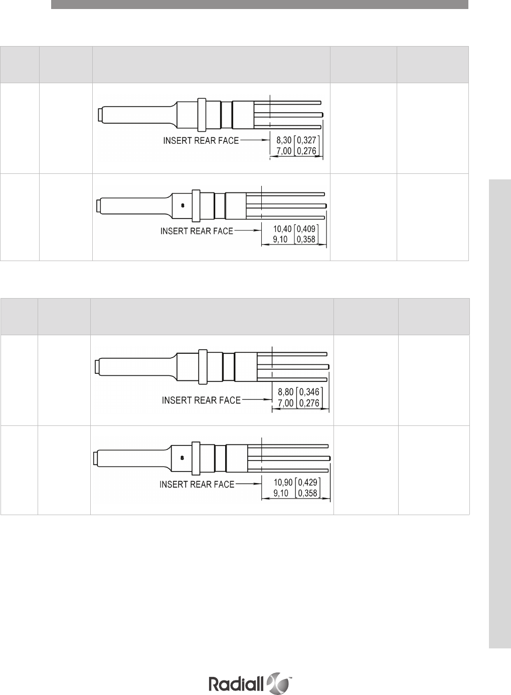
PC TAIL COAX CONTACTS Rear Release Rear Removable
Contacts
NOTES:
(1) Contacts Ins/ext tool: 282547 (M81969/28-02)
(2) For PC drill patern please contact Radiall
SIZE 12 PRE-TINNED PC TAIL
SIZE 12 PC TAIL mating interface design as per EN3155-030 & 031
Contact
type Part number (1) Contact drawing (2)
Rear extension from
all insert
inch (mm)
Rear extension from
70C12 insert only
inch (mm)
Pin 618149002
.275 / .327
(7.00 / 8.30)
.307 / .358
(7.80 / 9.10).
Pin 618149003
.358 / .409
(9.10 / 10.40)
.390 / .441
(9.90 / 11.20).
Contact
type Part number (1) Contact drawing (2)
Rear extensionfrom
all insert
inch (mm)
Rear extension from
70C12 inserts only
inch (mm)
Pin 618149006
.275 / .347
(7.00 / 8.80)
.307 / .379
(7.80 / 9.60).
Pin 618149007
.358 / .429
(9.10 / 10.90)
.390 / .461
(9.90 / 11.70).
MPX SERIES
5-29
Our Most Important Connection is with You.™
Go online for data sheets & assembly instructions Visit www.radiall.com and enter the part number
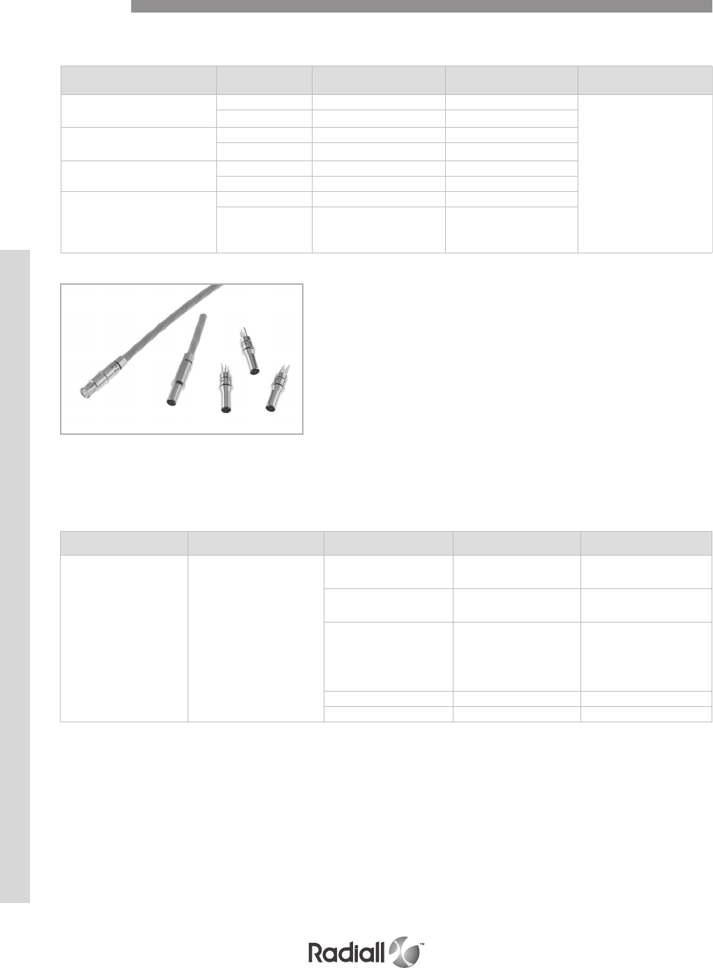
SIZE 8 CRIMP CONTACTS
design as per EN3155-034 & 035 interchangeable with 042 & 043 interface in accordance with M39029/95
Cable Contact Type Part number (1)
Non Environmental
Part number (1)
Environmental INS/Ext Tool
ABS972
ABS1503KD24
Pin 620175010 620175011
282549001
M81969/14.06
Socket 620075010 620075011
TENSOLITE
NF24Q100 (100Ω)
Pin 620175050 620175051
Socket 620075050 620075051
GORE RCN8487-1
(110Ω)
Pin 620175021 620175020
Socket 620075021 620075020
THERMAX
956S-4T200
GORE RCN8422
(110Ω)
Pin 620179002 620179001
Socket 620079002 620079001
NOTES:
(1) Ins/Ext tool: 282549001 (M81969/28-03)
(2) Add 001 at the end of the contact part number to be provided with a sealing boot with the contact
(3) Non environmental size 8 pin contacts are delivered with an alignment boot (p/n: 618920) to reduce the play at the contact extremity
QUADRAX CONTACTS Rear Release Rear Removable
SIZE 8 QUADRAX CONTACTS design as per EN3155-072 & 073
Contacts
CONCENTRIC TWINAX CONTACTS Rear Release Rear Removable
Contact size (1 & 3) Contact arrangement Cable Pin contact (2) Socket contact (2)
8
6T4
62T2
20T4
11T2
T6
47T2
C12T6
EN 3375-004
EN 3375-005 618160 618060
EN 3375-003
M17/176-00002 618161 618061
EN 3375-003
EN 3375-004
EN 3375-005
M17/176-00002
618162 618062
ECS 700 618166 618066
M17/176-00002 618180 /
MPX SERIES
5-30
Our Most Important Connection is with You.™
Go online for data sheets & assembly instructions Visit www.radiall.com and enter the part number
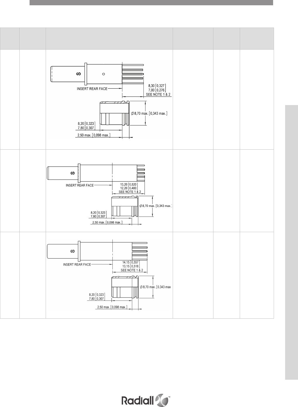
NOTES:
(1) Non environmental size 8 pin contacts are delivered with an alignment boot (p/n: 618920) to reduce the play at the contact extremity
This alignment boot protrudes 2.5mm max from the rear face of the insert; these 2.5mm are taken into account in the dimensions listed above
Contacts
CONCENTRIC TWINAX CONTACTS Rear Release Rear Removable
SIZE 8 PC TAIL CONTACTS mating interface design as per EN3155-034 & 035
Contact
type
Part
number (4) Contact drawing
Rear extension from
all insert
inch (mm)
Pc tail length
inch (mm)
Rear extension
from 62T2 insert
only
inch (mm)
Pin 618 163
.275 / .327
(7.00 / 8.30)
.275 / .327
(7.00 / 8.30)
.199 / .250
(5.05 / 6.35)
Pin 618 164
.480 / .520
(12.20 / 13.20)
.098 / .138
(2.50 / 3.50)
.403 / .443
(10.25 / 11.25)
Pin 618164001
.518 / .557
(13.15 / 14.15)
.234 / .238
(5.95 / 6.05)
.441 / .480
(11.20 / 12.20)
MPX SERIES
5-31
Our Most Important Connection is with You.™
Go online for data sheets & assembly instructions Visit www.radiall.com and enter the part number
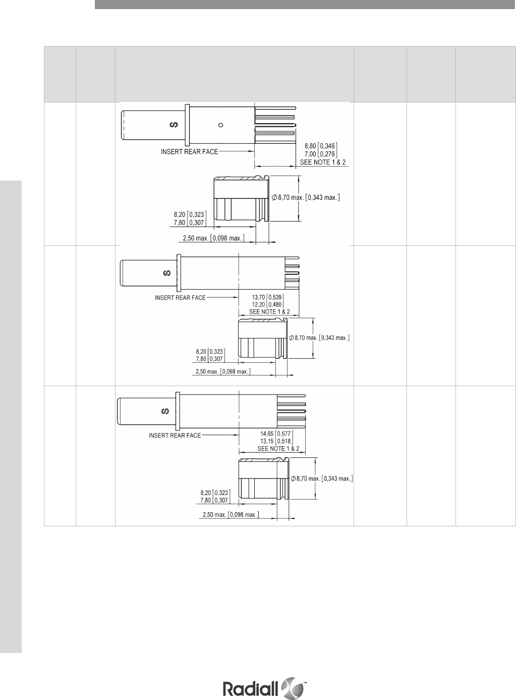
NOTES:
(1) Non environmental size 8 pin contacts are delivered with an alignment boot (p/n: 618920) to reduce the play at the contact extremity
This alignment boot protrudes 2.5mm max from the rear face of the insert; these 2.5mm are taken into account in the dimensions listed above
CONCENTRIC TWINAX CONTACTS Rear Release Rear Removable
SIZE 8 PRE-TINNED PC TAIL CONTACTS
Contacts
Contact
type
Part
number (1) Contact drawing
Rear extension
from
all insert
inch (mm)
Pc tail length
inch (mm)
Rear extension
from 62T2 insert
only
inch (mm)
Pin 618163005
.275 / .347
(7.00 / 8.80)
.297 / .347
(7.55 / 8.80)
.199 / .270
(5.05 / 6.85)
Pin 618164002
.480 / .540
(12.20 / 13.70)
.098 / .157
(2.50 / 4.00)
.403 / .463
(10.25 / 11.75)
Pin 618164003
.518 / .577
(13.15 / 14.65)
.234 / .258
(5.95 / 6.55)
.441 / .500
(11.20 / 12.70)
MPX SERIES
5-32
Our Most Important Connection is with You.™
Go online for data sheets & assembly instructions Visit www.radiall.com and enter the part number
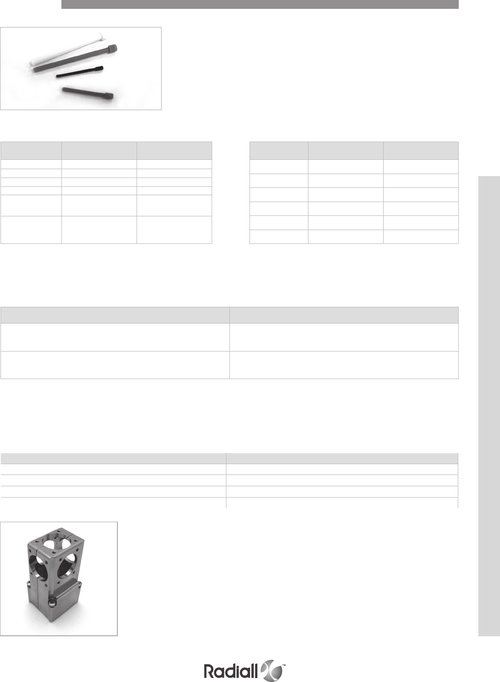
Accessories
Description Part number
EMI backshell for cavities A, C & E 618801002
EMI backshell for cavities B, D & F 618800002
Backshell termination 618802010
Backshell blank termination 618802011
BACKSHELLS
Backshells are made of aluminium alloy and are cadmium yellow chromate plated. To order one complete
backshell you must order separately an EMI backshell plus a combination of backshell terminations (i.e.
one complete backshell for cavity A = 4x 618802011 + 1x 618802010 + 1x 618801002)
SEALING PLUGS FILLER PLUGS
Cavity size Sealing plug P/N Color
22 620920 black
20 620921 red
16 620922 blue
12 620923 yellow
5618910 for pin
618912 for socket white
8618911 for pin
618913 for socket red
Cavity size Filler plug P/N Color
22 616910 black
20 616911 red
16 616912 blue
12 616913 yellow
5 618910 + 618915 white
8 618911 + 618915 red
CAVITY REDUCERS
The cavity reducers are not removable from the insert once installed. They are made of copper alloy and
are nickel plated to allow contact cavity grounding.
Cavity reducer type Part number
From pin size 8 to size 12 Environmental: 618940001
Non environmental: 618940
From socket size 8 to size 12 Environmental: 618941001
Non environmental: 618941
MPX SERIES
5-33
Our Most Important Connection is with You.™
Go online for data sheets & assembly instructions Visit www.radiall.com and enter the part number

DUMMY INSERTS:
MPXE10: dummy insert for A, C and E shell cavities
MPXE20: dummy insert for B, D and F shell cavities
POLARIZATION KIT & SCREWS
A kit of 2 screws that are used to fix the polarization posts or keys retention plate
is available under P/N: 618985
A polarization kit for plug is P/N 618811002 and for receptacle it is P/N 618811001.
Torque is 0.7 N.m
Accessories
Description Part number
Conductive dust cap for receptacle shell 618953001
Conductive dust cap for plug shell 618953002
Non conductive dust cap for plug shell 618953
DUST CAPS
Description Part number
O-ring for inserts for A,C & E cavities 618953020
O-ring for inserts for B,D & F cavities 618953021
O-RING FOR INSERTS
Description Part number
Coupling seals for A,C & E shell cavities 618953010
Coupling seals for B,D & F shell cavities 618953011
COUPLING SEALS
Description Part number
Kit made of one EMI spring for A,C & E shell cavities
and of one EMI spring for B, D & F 618810
EMI spring for A,C & E shell cavities 618810001
EMI spring for B,D & F shell cavities 618810002
EMI SPRING
MPX SERIES
5-34
Our Most Important Connection is with You.™
Go online for data sheets & assembly instructions Visit www.radiall.com and enter the part number
The table below gives A and B dimension values (A and B = distance between the front flange of the
connector and the rear face of the insert.
See drawings pages 5-36 to 5-41 for A and B description.
Insert description
A and/or B dimension
for environmental plug
inch (mm)
A and/or B dimension
for non environmental plug
inch (mm)
60, T6, 11C2, 34
C12T6, 24, 35, 47T2,13T4
6T4, 11T2, 25, 20T4, 20Q4, Q6, Q11
.386 / .449 (9.80 / 11.40)
No rear extension
of inserts from shell
150, 100 .228 /.295 (5.80 / 7.50)
62T2, 68Q4
A: Signal contacts
.228 /.295 (5.80 / 7.50)
B: Power contacts
.468 /.512 (11.90 / 13.00)
70C12, 126, 118Q2
A: Signal contacts
.228 /.295 (5.80 / 7.50)
B: Power contacts
.386 /.449 (9.80 / 11.40)
Insert description
A and/or B dimension for
environmental receptacle
inch (mm)
A and/or B dimension for
non environmental receptacle
inch (mm)
60, T6, 11C2, 34
C12T6, 24, 35, 47T2, 13T4
6T4, 11T2, 25, 20T4, 20Q4, Q6, Q11
1.610 / 1.657 (40.90 / 42.10) 1.275 / 1.313 (32.40 / 33.35)
150, 100, 126 1.441 / 1.492 (36.60 / 37.90) 1.171 / 1.215 (29.75 / 30.85)
62T2, 68Q4, 118Q2
A: Signal contacts
1.441 / 1.492 (36.60 / 37.90)
B: Power contacts
1.512 / 1.557 (38.40 / 39.55) 1.171 / 1.215 (29.75 / 30.85)
70C12 1.457 / 1.518 (37 / 38.55)
Dimensions
RECEPTACLE
PLUG
MPX SERIES
5-35
Our Most Important Connection is with You.™
Go online for data sheets & assembly instructions Visit www.radiall.com and enter the part number

NON ENVIRONMENTAL ENVIRONMENTAL
Receptacle Size 2 Dimensions
MPX SERIES
5-36
Our Most Important Connection is with You.™
Go online for data sheets & assembly instructions Visit www.radiall.com and enter the part number
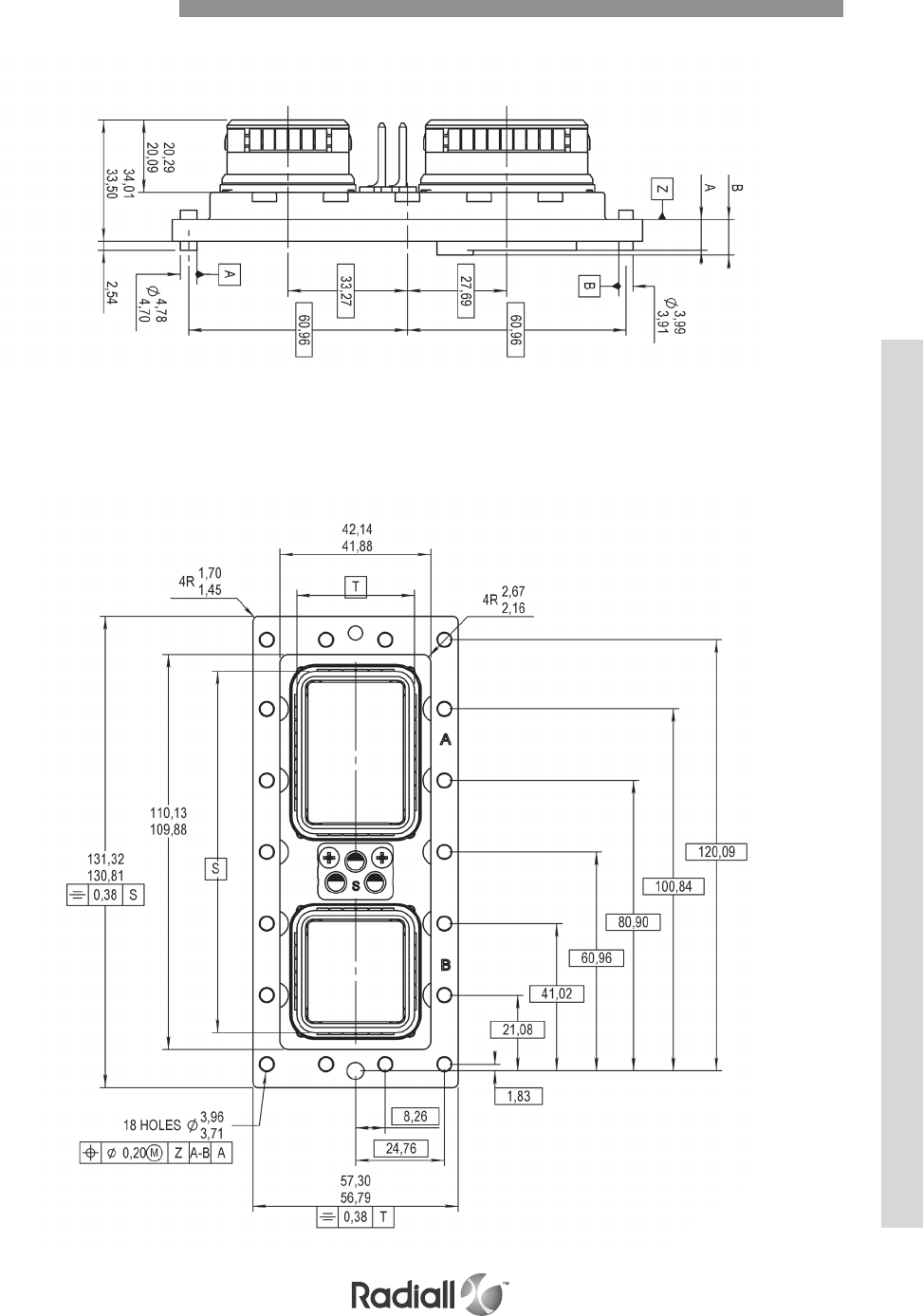
NON ENVIRONMENTAL ENVIRONMENTAL
Plug Size 2 Dimensions
MPX SERIES
5-37
Our Most Important Connection is with You.™
Go online for data sheets & assembly instructions Visit www.radiall.com and enter the part number
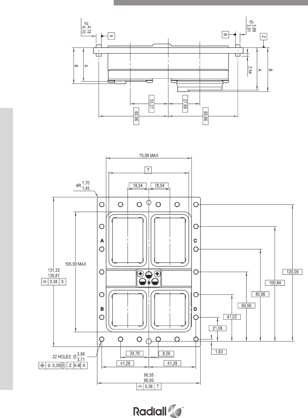
NON ENVIRONMENTAL ENVIRONMENTAL
Receptacle Size 3 Dimensions
MPX SERIES
5-38
Our Most Important Connection is with You.™
Go online for data sheets & assembly instructions Visit www.radiall.com and enter the part number
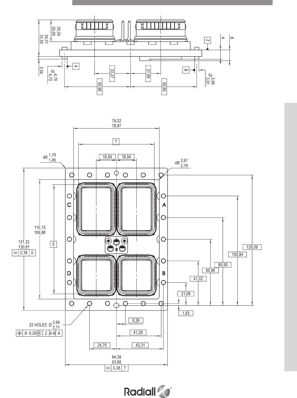
NON ENVIRONMENTAL ENVIRONMENTAL
Plug Size 3 Dimensions
MPX SERIES
5-39
Our Most Important Connection is with You.™
Go online for data sheets & assembly instructions Visit www.radiall.com and enter the part number
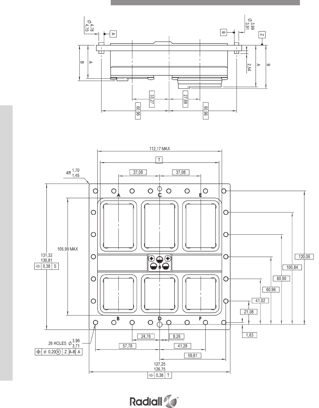
NON ENVIRONMENTAL ENVIRONMENTAL
Receptacle Size 4 Dimensions
MPX SERIES
5-40
Our Most Important Connection is with You.™
Go online for data sheets & assembly instructions Visit www.radiall.com and enter the part number

NON ENVIRONMENTAL ENVIRONMENTAL
Plug Size 4 Dimensions
MPX SERIES
5-41
Our Most Important Connection is with You.™
Go online for data sheets & assembly instructions Visit www.radiall.com and enter the part number
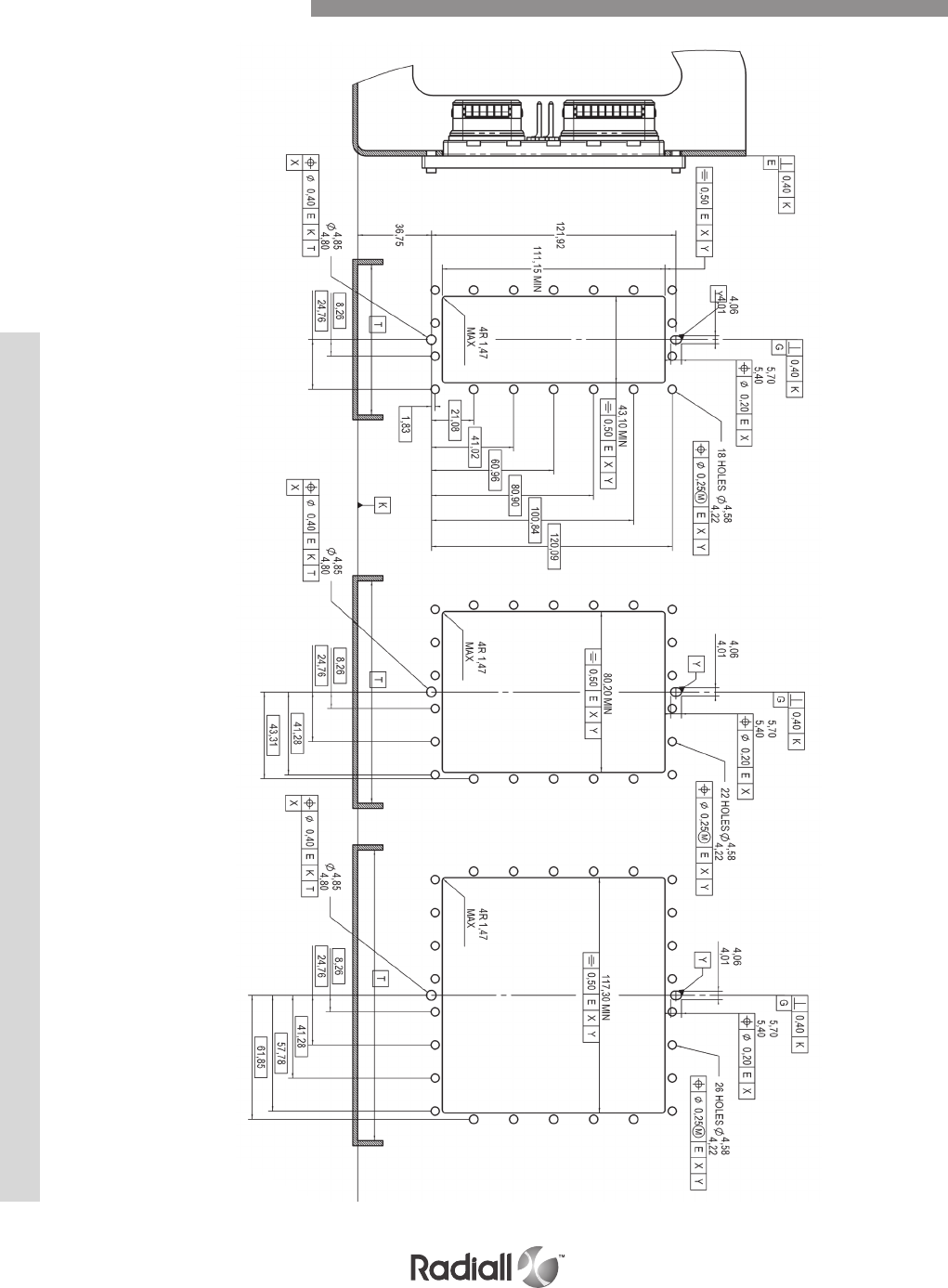
SIZE 2 SIZE 3 SIZE 4
Rack Plug Panel Cut-Out
MPX SERIES
5-42
Our Most Important Connection is with You.™
Go online for data sheets & assembly instructions Visit www.radiall.com and enter the part number
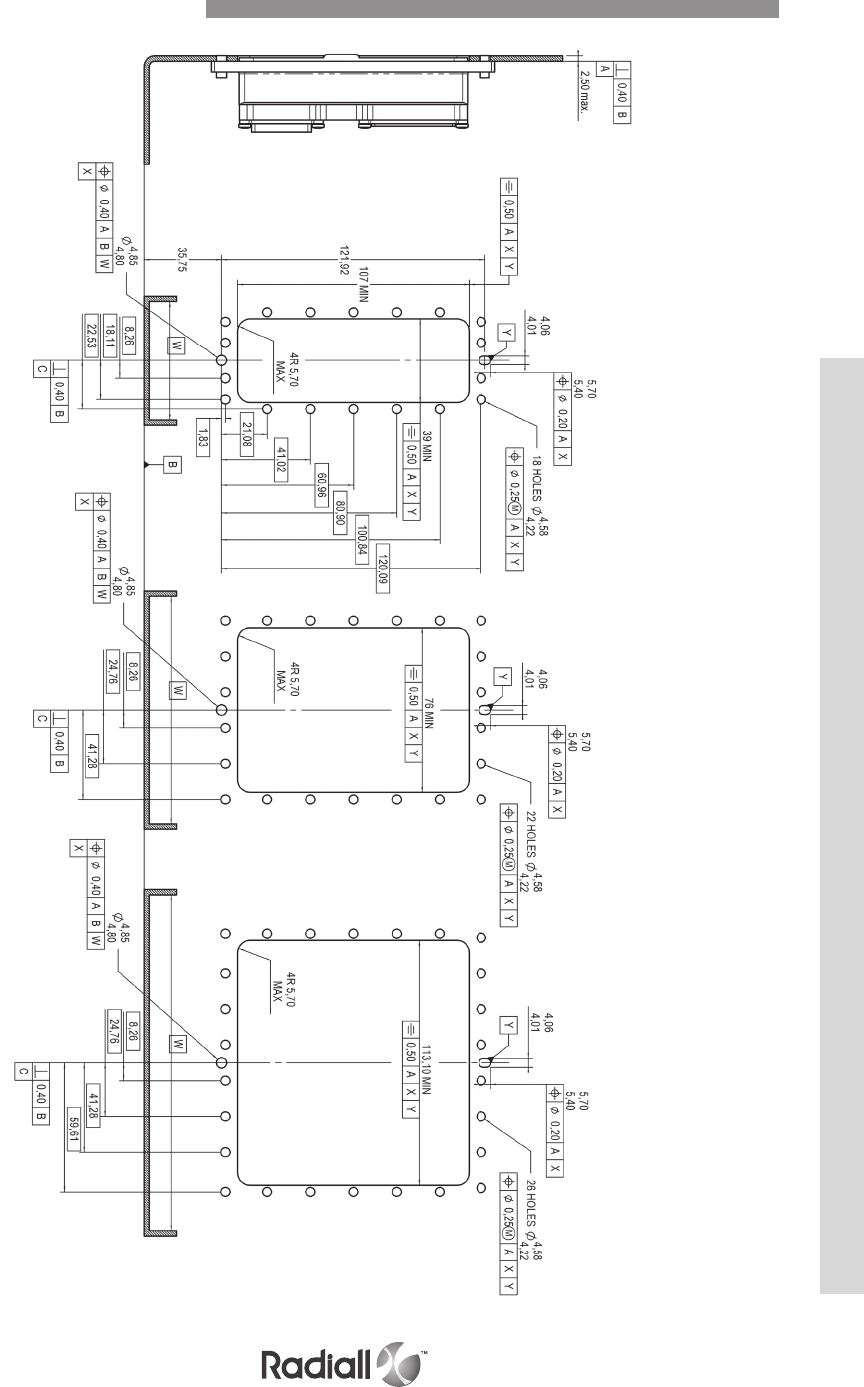
SIZE 2 SIZE 3 SIZE 4
Equipment Receptacle Panel Cut-Out
MPX SERIES
5-43
Our Most Important Connection is with You.™
Go online for data sheets & assembly instructions Visit www.radiall.com and enter the part number

Notes
MPX SERIES
5-44
Our Most Important Connection is with You.™
Go online for data sheets & assembly instructions Visit www.radiall.com and enter the part number
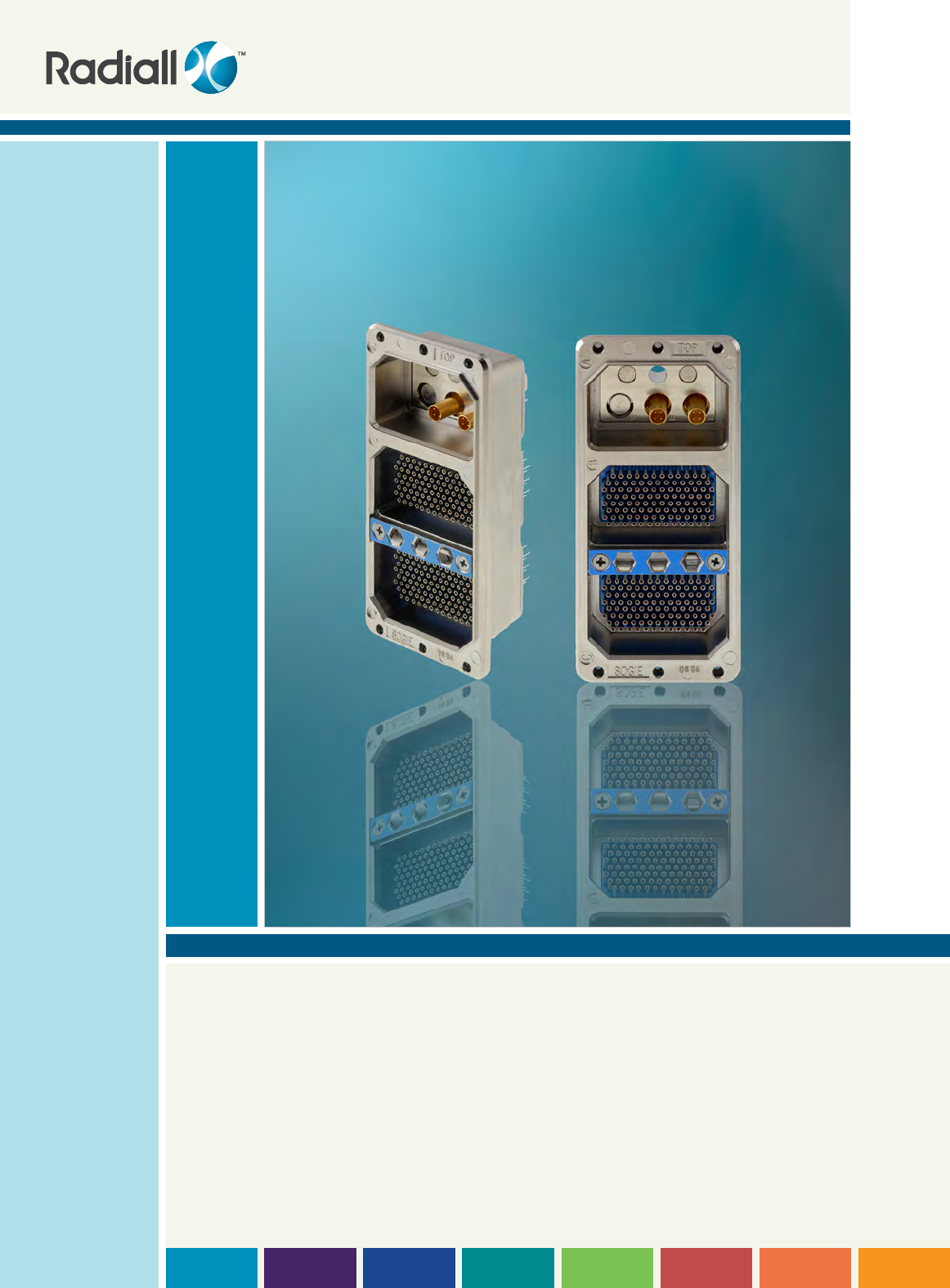
SECTION 6
DSX Series
SAE AS81659
Arinc 404

Our Most Important Connection is with You.™

SECTION 6 TABLE OF CONTENTS
6-3
Our Most Important Connection is with You.™
Go online for data sheets & assembly instructions Visit www.radiall.com and enter the part number
Introduction ......................................... 6-4
Applications ........................................ 6-5
DSX – SAE AS81659
Product overview .................................... 6-6
Technical characteristics: ................... 6-7 & 6-8
- Electrical ............................................ 6-7
- Mechanical & Environmental ..................... 6-7
- Materials ............................................ 6-8
- Masses .............................................. 6-8
How to order .......................................... 6-9
Contact arrangement ..................... 6-10 to 6-12
Modification code .......................... 6-13 to 6-18
Polarization code ................................... 6-19
Polarization code table .................... 6-19 to 6-20
Contacts: ................................... 6-21 to 6-27
- Signal and power contacts ....................... 6-21
- Thermocouple contacts .......................... 6-21
- Contacts with pc tail ............................. 6-22
- Contacts with wire wrap post .................. 6-23
- Coaxial crimp contacts .................. 6-23 to 6-25
- Concentric twinax crimp contact ............... 6-26
- Triax crimp contacts ............................. 6-26
- Triax contact with pc tail ........................ 6-27
- Fiber optic contacts and accessories .......... 6-28
Accessories ............................... 6-29 to 6-30
Dimensions ................................ 6-31 to 6-34
Panel cut out ....................................... 6-35
Cross reference ........................... 6-36 to 6-39
DSX - F
How to order ........................................ 6-40
Contacts: ............................................ 6-41
- Contacts with pc tail .............................. 6-41
- Contacts with wire wrap post ................... 6-41
- Coaxial crimp contacts ........................... 6-41
DSX – DATA BUS
How to order ........................................ 6-42
Technical characteristics ......................... 6-42
Contact arrangement ............................. 6-43
Dimensions ................................. 6-44 & 6-45
Twinax contacts .................................... 6-45
DSX – ARINC 404 shell type B
How to order ........................................ 6-46
Technical characteristics: ........................ 6-47
- Materials .......................................... 6-47
- Electrical .......................................... 6-47
- Mechanical & Environmental ................... 6-47
Contact arrangements .................... 6-48 & 6-49
Contacts: .................................. 6-50 to 6-53
- Signal and power crimp contacts .............. 6-50
- Contacts with pc tail ............................. 6-50
- Contacts with wire wrap post .................. 6-51
- Solder cup contacts ............................. 6-51
- Thermocouple contacts ......................... 6-51
- Fiber optic contacts .............................. 6-51
- Coaxial crimp contacts .................. 6-52 & 6-53
Accessories ........................................ 6-53
Dimensions ................................. 6-54 & 5-55
DSX – EMI/RFI
Introduction ........................................ 6-56
Part numbering .................................... 6-56
Technical characteristics ......................... 6-56
Materials ............................................ 6-56
DSX – ARINC 404 shell type A
Technical characteristics: ........................ 6-57
- Electrical .......................................... 6-57
- Mechanical & Environmental ................... 6-57
- Materials .......................................... 6-57
How to order ........................................ 6-58
Contact arrangement ............................. 6-58
Modification code .................................. 6-59
Contacts ............................................ 6-60
Accessories ........................................ 6-60
Dimensions ......................................... 6-60
Panel cut out ....................................... 6-60
Tools ................................................. 6-61
Contents

DSX SERIES
6-4
Our Most Important Connection is with You.™
Go online for data sheets & assembly instructions Visit www.radiall.com and enter the part number
The Radiall DSX rack and panel series are multipin rectangular connectors used to
electrically interface avionics equipment to equipment rack. Usually the plug is installed on
the avionics rack and the receptacle on the equipment box. The mated locking mechanism
is provided for the equipment and cabinet and is not a part of the connector pair.
These connectors are widely used in applications such as:
- Commercial / military aircraft and helicopters
- Radar systems
- Power circuits
- In-flight electronic instrumentation
- Flight simulators, etc...
The following versions are offered:
DSX – SAE AS81659: connectors conforming to SAE AS81659 including connectors listed on the
QPL81659
DSX - ARINC 404 shell type B: connectors conforming to ARINC 404 shell type B - polarized shells
DSX - ARINC 404 shell type A: connectors conforming to ARINC 404 shell type A - single shell
(without polarization)
DSX - F: connectors for front release front removable contacts (receptacle only)
DSX - DATA BUS: connectors for interconnection of multiplexed digital links
DSX - EMI/RFI: shielded connectors
DSX – SAE AS81659
These connectors fully conform to SAE AS81659 specifications and are listed on the
associated Qualified Product List. They are available in four shell sizes (1, 2, 3 and 4) which can
respectively accept 1, 2, 3 and 4 inserts. Inserts are offered in various contact arrangements
accommodating rear release rear removable signal (size 22 ), power (sizes 5, 12, 16 and
20HD), coaxial (sizes 1, 3, 5, 7, 9 and 15), concentric twinax (sizes 5 and 9), triax (sizes 5 and
9) contacts in crimp, wire wrap or PC tail termination. Radiall’s 29504 fiber optic termini are
also available. Both environmental and non environmental connectors are offered.
Mismating is prevented by a polarizing system which provides 216 polarizing positions. For
military part numbers, applicable polarizing positions range goes from 00 through 99 only.
DSX - ARINC 404 SHELL TYPE B
Arinc 404 shell type B are the commercial version. Here are the commercial features compared to the
military version:
- They use both size 20HD and size 20 contacts.
- They are non environmental. Inserts are fitted with a rubber separator on the back
of their wiring which does not provide sealing but provides wire protection.
- Removable size 5 and 9 coaxial contacts are not interchangeable with those of the military type.
- Insert retention plate is yellow anodized instead of blue anodized on the military version.
DSX - ARINC 404 SHELL TYPE A
DSX - ARINC 404 shell type A connectors are only available in shell size 1. They use
ARINC 404 shell type B inserts; only one insert can be installed in the connector shell.
Shell type A has no polarization system, mismating is prevented by keystone shaped
shells. DSX ARINC 404 shell type A connectors cannot be fitted with any backshell.
Introduction

6-5
Our Most Important Connection is with You.™
Go online for data sheets & assembly instructions Visit www.radiall.com and enter the part number
DSX - F
These connectors are used to form the electrical interface between avionics equipment to rack equipment.
©Eurocopter/photo Patrick PENNA
Introduction
Applications
DSX - F receptacle connectors are available in four shell sizes (1, 2, 3 and 4) and are designed to
be fitted with front release front removable contacts offered in pc tail and wire wrap termination.
Inserts are offered with or without an interfacial seal (in both cases they are not and are fitted with
a separator) and are available in the following contact arrangements: 106, 67, 57, 45, 40, 33C4, 26.
DSX - F connectors are fully intermateable with connectors of the
ARINC 404 shell type B and SAE AS81659 versions.
DSX - DATA BUS
These connectors have been designed to ensure the interconnection
of multiplexed digital links used in military equipment.
DSX - EMI / RFI
In response to the continuing development of electronic systems used in ever harsher environments,
these connectors have been designed to improve the shielding effectiveness against electromagnetic
and radio frequency interferences (EMI/RFI) as well as electromagnetic pulses (EMP).
DSX SERIES
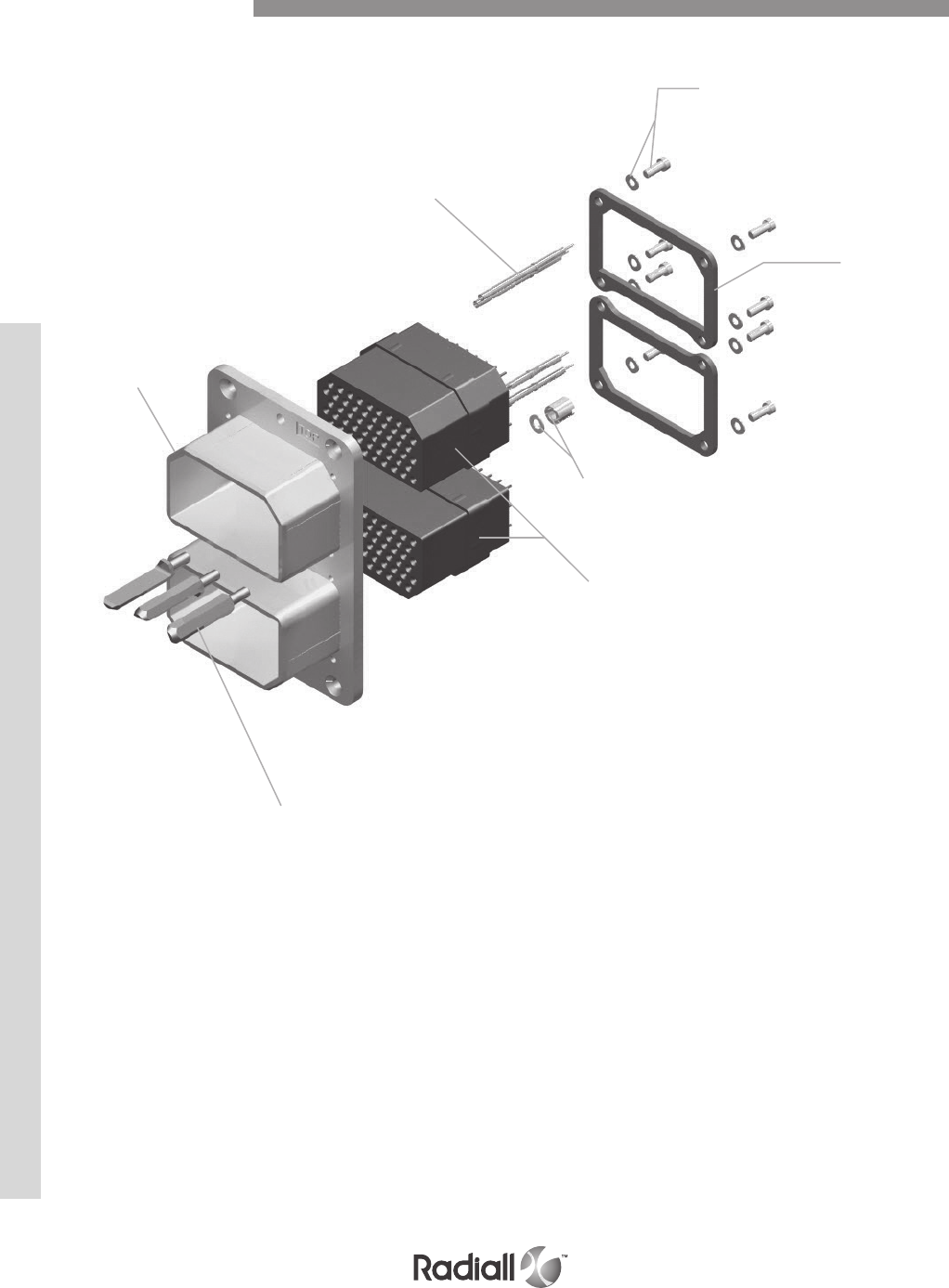
DSX SERIES
6-6
Our Most Important Connection is with You.™
Go online for data sheets & assembly instructions Visit www.radiall.com and enter the part number
Detailed view of the various parts of this series connector.
Contacts
Shell
Polarization posts
Insert
retention
plates
Screws &
washers
Inserts
Polarizing
post nut &
washer
Product Overview
6-7
Our Most Important Connection is with You.™
Go online for data sheets & assembly instructions Visit www.radiall.com and enter the part number
ELECTRICAL
Contact size 22 20HD 16 12
Axial load N (lbs) 66N (15) 89N (20) 111N (25) 133.5N (30)
Contact size AWG Cross section
mm2 (sq.in)
Min. Outside dia.
mm (inch)
Max. outside dia.
mm (inch) Max current (A)
22
22 0.38 (0.015)
0.76 (0.030) 1.4 (0.055)
5
24 0.21 (0.008) 3
26 0.14 (0.006) 2
20HD
20 0.60 (0.024)
1 (0.039) 1.8 (0.071)
7.5
22 0.38 (0.015) 5
24 0.21 (0.008) 3
16
16 1.34 (0.053)
1.70 (0.067) 2.6 (0.102)
13
18 0.93 (0.037) 10
20 0.60 (0.024) 7.5
12
12 3.18 (0.125)
2.4 (0.094) 3.4 (0.134)
23
14 1.91 (0.075) 17
16 1.34 (0.052) 13
For cavity 5
8 9.00 (0.354)
3.4 (0.134) 6.48 (0.255)
46
10 5.00 (0.197) 33
12 3.18 (0.125) 23
14 1.91 (0.075) 17
MECHANICAL & ENVIRONMENTAL
Temperature range: -65°C (-85°F) / +125°C (+257°F)
Temperature life: 1000 hours at +125°C (+257°F)
Salt spray: EIA 364-26 (MIL-STD-1344A method 1001.1 test condition B (48 hours))
Altitude moisture injection: Insulation resistance > 100 M Ω altitude 50000 feet
Fluid resistance: resistance to 20 hours immersion in fluids MIL PRF 5606 & MIL PRF 23699
Durability: 500 matings & unmating cycles
Vibration: EIA 364-28 (MIL-STD-1344A method 2005 test condition IV (20g – 10-2000Hz))
Shock: EIA 364-27 (MIL-STD-1344A method 2004 test condition A (50g -11ms – half sine))
Mating force: < 200N (45 lbs) per insert
Insert retention force: > 534N (120 lbs) in each direction
Contact retention force: max axial displacement = 0.3mm (0.012 inches)
Technical Characteristics
Magnetic permeability: <2 µ
Insulation resistance: >5000 MΩ
Dielectric withstanding voltage: see contact arrangement on pages 6-10 to 6-12
Contact resistance: according to requirements of SAE AS39029
Coax contacts electrical characteristics
Nominal impedance: 50 Ω
VSWR
- Sizes 5, 7 and 9: 1.3 from DC to 1500MHz
- Sizes 1 and 3: 1.3 from DC to 5000 MHz
DSX SERIES

DSX SERIES
6-8
Our Most Important Connection is with You.™
Go online for data sheets & assembly instructions Visit www.radiall.com and enter the part number
MATERIALS
MASSES (estimates)
Description Material Plating
Shell Aluminium alloy Cadmium yellow chromate*
Insert Thermosetting resin /
Metallic insert Aluminium alloy Cadmium clear chromate*
Interfacial seal & grommet Silicone rubber /
Retention clip Copper alloy /
Contact Copper alloy Gold over nickel under plate
Insert retention plate Aluminium alloy Blue anodised*
Polarizing posts Stainless steel /
Polarizing keys Zinc alloy Cadmium yellow chromate
Polarizing keys retention plate Aluminium alloy Cadmium yellow chromate*
Screws, washers, clinch-nuts Corrosion resistant steel /
Sealing plugs and filler plugs PTFE /
Sealing boots and sleeves Fluorinated silicon rubber /
Sealing bushing PEI /
Junction shells Aluminium alloy Yellow anodized or nickel plated
Description Weight g (oz)
Plug shell size 1 30 (1.05)
Plug shell size 2 45 (1.60)
Plug shell size 3 60 (2.15)
Plug shell size 4 85 (3)
Receptacle shell 1 30 (1.05)
Receptacle shell 2 50 (1.75)
Receptacle shell 3 85 (3)
Receptacle shell 4 115 (4.05)
Plastic insert 20 (0.70)
Metallic insert 35 (1.25)
Junction shells 25 (0.88)
* More platings are available, see descriptions in modification codes
Technical Characteristics

6-9
Our Most Important Connection is with You.™
Go online for data sheets & assembly instructions Visit www.radiall.com and enter the part number
DSX N 4 P G S 40 S S8S S26S S45P 00 01
Important note: If you want to get connectors marked with the military part number (i.e.
M81659/66A2-0083) you must order by using the military part number. Radiall part numbers
qualified to SAE AS81659 versus military part numbers are listed from pages 6-36 to 6-39.
NOTES:
(1) For reduced crimp barrel, thermocouple or fiber optic contacts, use code X and order contact separately.
(2) For contact arrangements which include coax or quadrax contacts, use termination code X . Quadrax and coax contacts must be ordered
separately.
(3) Without polarization code the connector is delivered with the polarizing system unassembled. With polarization code 00: the connector is
delivered without polarizing system. With polarization code from 01 to 216: the connector is delivered with polarization hardware assembled as
defined by code. Polarization codes for connector qualified to SAE AS81659 are ranging from 00 to 99 only.
(4) PC tail and wire wrap contacts must be used only with non environmental version. PC tail and wire wrap contacts are delivered installed. For
67, 32C4 and 33C4 contact arrangements, size 16 contacts are delivered not installed and in crimp termination.
How to Order Connectors
Gang A
Series
Class
N: Non environmental (without grommet and interfacial seal)
E: Environmental (with grommet and interfacial seal)
T: Connector with interfacial seal on insert with protruding contacts only
Shell size
1: One gang shell
2: Two gang shell
3: Three gang shell
4: Four gang shell
Shell type
R: Receptacle
P: Plug
Grounding EMI/RFI
G: with grounding spring (only for plug connector)
Termination style
X: Without contacts (for crimp contacts only)
S: Crimp (1)
V: Wire wrap two levels (4)
W: Wire wrap three levels (4)
Y: PC tail contact (4)
Contact arrangement (2)
See available contact arrangements on pages 6-10 to 6-12
Contact type
S: Socket
P: Pin
Gang B
Gang C
Gang D
Modification code
See pages 6-13 to 6-19 for selection
Modification code will help in choosing the appropriate plating for your application.
Polarization code (3)
See pages 6-20 to 6-21 for selection
DSX SERIES
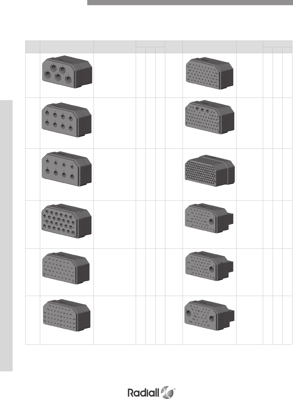
DSX SERIES
6-10
Our Most Important Connection is with You.™
Go online for data sheets & assembly instructions Visit www.radiall.com and enter the part number
Insert
name Number of contacts Dielectric Withstanding
Voltage (DWV)
Class Insert
name Number of contacts DWV Class
N E T N E T
C5(1)
5 x #5 (power)
2500V – 60Hz
This insert is
available in
class N only.
57(1)
57 x #20HD
1500v – 60Hz
8
8 x #12
1500V – 60Hz 67
64 x #20HD
3 x #16
1000V - 60Hz
D8
4 x #16
4 x #12
1500V – 60Hz 106
106 x #22
1000V - 60Hz
(2)
26
26 x #16
1500V – 60Hz 40C1
1 x #5 (coax)
39 x #20HD
1500V – 60Hz
40
40 x #20HD
1500V – 60Hz 40T1(1)
1 x #5 (coax)
39 x #20HD
1500V – 60Hz
Size 5
contact cavity
grounded to
the shell
45
45 x #20HD
1500V – 60Hz 32C2
2 x #5 (coax)
30 x #20HD
1000V - 60Hz
Pin insert mating side shown
Contact Arrangements
Class N for non environmental insert
Class E for environmental insert
Class T for insert with interfacial seal only
NOTES:
(1) Contact arrangements are not referenced in the MS3157 and SAE AS81659 standards
(2) class T insert are for pin contacts only except insert arrangement 106; 36C7 and 36T7 which are for socket contacts only

6-11
Our Most Important Connection is with You.™
Go online for data sheets & assembly instructions Visit www.radiall.com and enter the part number
Insert
name Number of contacts DWV Class Insert
name Number of contacts DWV Class
N E T N E T
32T2(1)
2 x #5 (coax)
30 x #20HD
1000V – 60Hz
Size 5 contact
cavities
grounded to
the shell
36C7(1)
7 x #5 (coax)
29 x #22
1000V – 60Hz
(2)
32C4
4 x #9 (coax)
4 x #16
24 x #20HD
1500V – 60Hz 36T7(1)
7 x #5 (coax)
29 x #22
1000V – 60Hz
Size 5 contact
cavities
grounded to
the shell
(2)
32T4(1)
4 x #9 (coax)
4 x #16
24 x #20HD
1500V – 60Hz
Size 9 contact
cavities
grounded to
the shell
MC2
2 x #1 (coax)
This insert
is metallic
33C4
4 x #5 (coax)
4 x #1625 x #20HD
1000V – 60Hz MC3
2 x #7 (coax)
1 x #3 (coax)
This insert
is metallic
33T4(1)
4 x #5 (coax)
4 x #16
25 x #20HD
1000V – 60Hz
Size 5 contact
cavities
grounded to
the shell
C8
8 x #9 (coax)
1000V – 60Hz
NOTE:
(1) Contact arrangements are not referenced in the MS3157 and SAE AS81659 standards
(2) class T insert are for pin contacts only except insert arrangement 106; 36C7 and 36T7 which are for socket contacts only
Contact Arrangements
Pin insert mating side shown
DSX SERIES
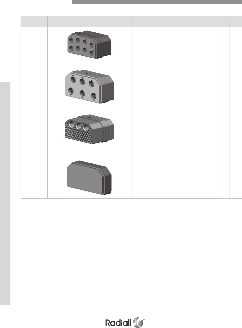
DSX SERIES
6-12
Our Most Important Connection is with You.™
Go online for data sheets & assembly instructions Visit www.radiall.com and enter the part number
Insert name Number of contacts DWV Class
N E T
T8*
8 x #9 (coax)
Size 9 contact cavities grounded to the shell.
Pin contact available only
6CU
6 x #8 Quadrax
Size 8
contact cavities grounded to the shell.
Non environmental only
81C3
78 x # 22
3 x #5 (coax)
1000V - 60Hz
for pin
contact
only
00* Dummy insert
Contact Arrangements
Pin insert mating side shown
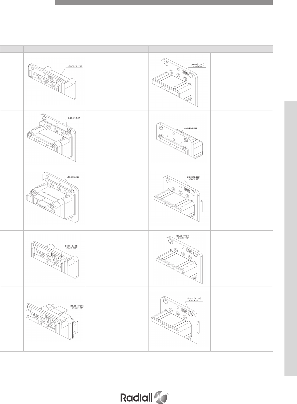
6-13
Our Most Important Connection is with You.™
Go online for data sheets & assembly instructions Visit www.radiall.com and enter the part number
Connectors can be front or rear mount. It should be noted that:
- There is only 4mm between the connector flange when fully mated. Please note that the modification
code and screw type should be selected accordingly.
- The modification code with floating eyelets can be mated with the fixed modification.
CODE Receptacle shell Plug shell
00
Sizes 1,2 & 3:
6 holes Ø3,05 (0.120)
Size 4:
10 holes Ø3,05 (0.120)
Sizes 1 & 2:
4 holes Ø3,05 (0.120)
c’sunk 90°
Size 3:
6 holes Ø3,05 (0.120)
c’sunk 90°
Size 4:
10 holes Ø3,05 (0.120) c’sunk
90°
01
Sizes 1 & 2:
4 clinch nuts 4.40
UNC 3B
Size 3: 6 clinch nuts 4.40 UNC
3B
Size 4: 10 clinch nuts 4.40 UNC
3B
Sizes 1 & 2: 4 clinch nuts 4.40
UNC 3B
Size 3: 6 clinch nuts 4.40 UNC
3B
Size 4: 10 clinch nuts 4.40 UNC
3B
02
Sizes 1, 2 & 3:
6 holes Ø3,05 (0.120) with
attaching tabs for RADIALL
backshell
Not Available
in Size 4
Sizes 1 & 2:
4 holes Ø3,05 (0.120) c’sunk 90°
with attaching tabs for RADIALL
backshell
Size 3:
6 holes Ø3,05 (0.120) c’sunk 90°
with attaching tabs for RADIALL
backshell
Not Available
in Size 4
03
Sizes 1 & 2:
4 holes Ø3,05(0.120) c’sunk 100°
Size 3:
6 holes Ø3,05(0.120) c’sunk 100°
Size 4:
10 holes Ø3,05(0.120)
c’sunk 100°
Sizes 1 & 2:
4 holes Ø3,05(0.120)
c’sunk 100°
Size 3:
6 holes Ø3,05(0.120)
c’sunk 100°
Size 4:
10 holes Ø3,05(0.120)
c’sunk 100°
04
Sizes 1 & 2:
4 holes Ø3,05(0.120) c’sunk 100°
with attaching tabs for RADIALL
backshell
Size 3:
6 holes Ø3,05(0.120) c’sunk 100°
with attaching tabs for RADIALL
backshell
Not Available
in Size 4
Sizes 1 & 2:
4 holes Ø3,05(0.120) c’sunk 100°
with attaching tabs for RADIALL
backshell
Size 3:
6 holes Ø3,05(0.120) c’sunk 100°
with attaching tabs for RADIALL
backshell
Not Available
in Size 4
Modification Code
DSX SERIES
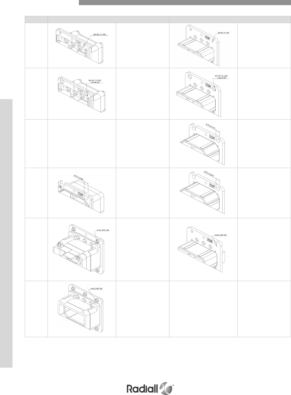
DSX SERIES
6-14
Our Most Important Connection is with You.™
Go online for data sheets & assembly instructions Visit www.radiall.com and enter the part number
Code Receptacle shell Plug shell
05
Sizes 1,2 & 3:
4 holes Ø4,80 (0.189)
Size 4:
10 holes Ø4,80 (0.189)
Sizes 1,2 & 3:
4 holes Ø4,80 (0.189)
Size 4:
10 holes Ø 4,80 (0.189)
08
Sizes 1 & 2:
4 holes Ø3,53 (0.139) c’sunk
82°
Size 3:
6 holes Ø3,53 (0.139)
c’sunk 82°
Sizes 1 & 2:
4 holes Ø3,53 (0.139) c’sunk
82°
Size 3:
6 holes Ø3,53 (0.139)
c’sunk 82°
12 --
-- Sizes 1, 2 & 3:
4 mounting slots 5,33 (0.210)
wide
13
Sizes 1, 2 & 3:
4 mounting slots 6,07 (0.239)
wide
Sizes 1, 2 & 3:
4 mounting slots 6,07 (0.239)
wide
17
Sizes 1 & 2:
4 clinch nuts
4.40 UNC 3B with attaching
tabs for RADIALL backshell
Size 3:
6 clinch nuts
4.40 UNC 3B with attaching
tabs for RADIALL backshell
Not Available
in Size 4
Sizes 1 & 2:
4 clinch nuts 4.40 UNC
3B with attaching tabs for
RADIALL backshell
Size 3:
6 clinch nuts 4.40 UNC
3B with attaching tabs for
RADIALL backshell
Not available in size 4
18
Sizes 1, 2 & 3:
6 clinch nuts
4.40 UNC 3B
Not Available
in Size 4 --
--
Modification Code
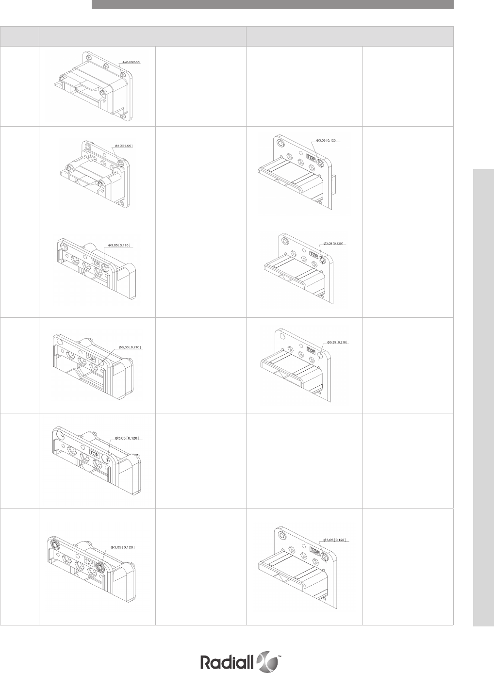
6-15
Our Most Important Connection is with You.™
Go online for data sheets & assembly instructions Visit www.radiall.com and enter the part number
Code Receptacle shell Plug shell
19
Sizes 1, 2 & 3:
6 clinch nuts
4.40 UNC 3B with
attaching tabs for RADIALL
backshell
Not Available
in Size 4
--
--
22
Sizes 1 & 2:
4 floating eyelets Ø3,05
(0.120) with attaching tabs for
RADIALL backshell
Size 3:
6 floating eyelets Ø3,05
(0.120) with attaching tabs for
RADIALL backshell
Not Available
in Size 4
Sizes 1 & 2:
4 floating eyelets Ø3,05
(0.120) with attaching tabs for
RADIALL backshell
Size 3:
6 floating eyelets Ø3,05
(0.120) with attaching tabs for
RADIALL backshell
Not Available
in Size 4
23
Sizes 1 & 2:
4 floating eyelets Ø3,05
(0.120
Size 3:
6 floating eyelets Ø3,05
(0.120)
Size 4:
10 floating eyelets Ø3,05
(0.120)
Sizes 1 & 2:
4 floating eyelets Ø3,05
(0.120)
Size 3:
6 floating eyelets Ø3,05
(0.120)
Size 4:
10 floating eyelets Ø3,05
(0.120)
24
Sizes 1, 2 & 3:
6 holes Ø5,33 (0.210)
Sizes 1, 2 & 3:
6 holes Ø5,33 (0.210)
26
Sizes 1 & 2:
4 holes Ø3,05(0.120) c’sunk
90°
Size 3:
6 holes Ø3,05(0.120) c’sunk
90°
Size 4:
10 holes Ø 3,05(0.120)
c’sunk 90°
--
--
33
Sizes 1 & 2:
4 flush front embedded
floating eyelets Ø3,05
(0.120)
Size 3:
6 flush front embedded
floating eyelets Ø3,05
(0.120)
Size 4:
10 flush front embedded
floating eyelets Ø3,05
(0.120)
Sizes 1 & 2:
4 flush rear embedded
floating eyelets Ø3,05
(0.120)
Size 3:
6 flush rear embedded
floating eyelets Ø3,05
(0.120)
Size 4:
10 flush rear embedded
floating eyelets Ø3,05
(0.120)
Modification Code
DSX SERIES
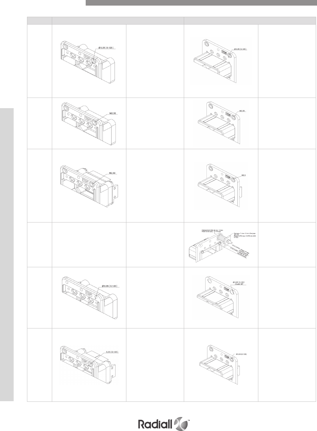
DSX SERIES
6-16
Our Most Important Connection is with You.™
Go online for data sheets & assembly instructions Visit www.radiall.com and enter the part number
Code Receptacle shell Plug shell
34
Sizes 1 & 2:
4 flush rear embedded
floating eyelets Ø3,05 (0.120)
Size 3:
6 flush rear embedded
floating eyelets Ø3,05 (0.120)
Size 4:
10 flush rear embedded
floating eyelets Ø3,05 (0.120)
Sizes 1 & 2:
4 flush front embedded
floating eyelets Ø3,05 (0.120)
Size 3:
6 flush front embedded
floating eyelets Ø3,05 (0.120)
Size 4:
10 flush front embedded
floating eyelets Ø3,05 (0.120)
35
Sizes 1 & 2:
4 flush front embedded
floating eyelets M2.5
threaded
Size 3:
6 flush rear embedded
floating eyelets M2.5
threaded
Sizes 1 & 2:
4 flush rear embedded
floating eyelets M2.5
threaded
Size 3: 6 flush rear
embedded floating eyelets
M2.5 threaded
36
Sizes 1 & 2:
4 flush front embedded
floating eyelets M2.5
threaded with attaching tabs
for RADIALL backshell
Size 3:
6 flush front embedded
floating eyelets M2.5
threaded with attaching tabs
for RADIALL backshell
Not Available
in size 4
Sizes 1 & 2:
4 flush front embedded
floating eyelets M2.5
threaded with attaching tabs
for RADIALL backshell
Size 3:
6 flush front embedded
floating eyelets M2.5
threaded with attaching tabs
for RADIALL backshell
Not Available
in size 4
55 --
-- Sizes 1, 2 & 3:
Spring loaded shell 6 places
60
Similar to modification code
00 except that the shell, keys
and keys retention plate are
nickel plated.
Similar to modification code
00 except that the shell, keys
and keys retention plate are
nickel plated.
61
Similar to modification code
22 except that the shell, keys
and keys retention plate are
nickel plated.
Not available in size 4
Similar to modification code
22 except that the shell, keys
and keys retention plate are
nickel plated.
Not available in size 4
Modification Code
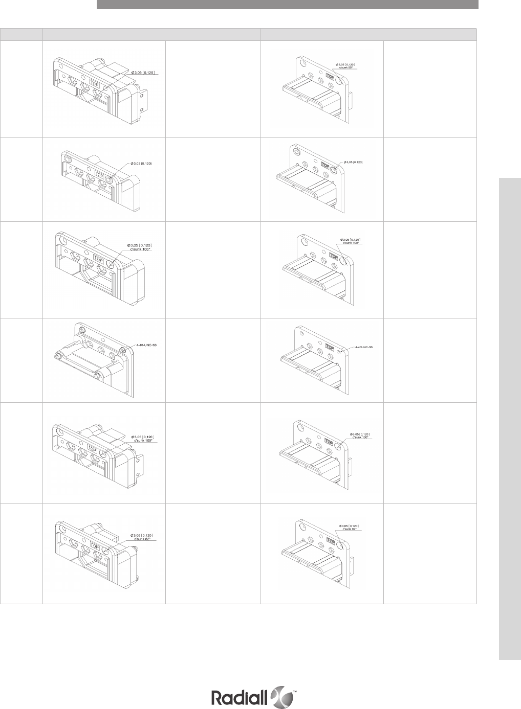
6-17
Our Most Important Connection is with You.™
Go online for data sheets & assembly instructions Visit www.radiall.com and enter the part number
Code Receptacle shell Plug shell
62
Similar to modification code
02 except that the shell, keys
and keys retention plate are
nickel plated.
Not available in size 4
Similar to modification code
02 except that the shell, keys
and keys retention plate are
nickel plated.
Not available in size 4
63
Similar to modification code
23 except that the shell, keys
and keys retention plate are
nickel plated.
Similar to modification code
23 except that the shell, keys
and keys retention plate are
nickel plated.
64
Similar to modification code
03 except that the shell, keys
and keys retention plate are
nickel plated.
Similar to modification code
03 except that the shell, keys
and keys retention plate are
nickel plated.
66
Similar to modification code
01 except that the shell, keys
and keys retention plate are
nickel plated.
Similar to modification code
01 except that the shell, keys
and keys retention plate are
nickel plated.
67
Sizes 1 & 2:
4 holes Ø3,05 (0.120) c’sunk
100° with attaching tabs for
RADIALL backshell
Size 3:
6 holes Ø3,05 (0.120) c’sunk
100° with attaching tabs for
RADIALL backshell
Shells are nickel plated.
Not Available in size 4
Sizes 1 & 2:
4 holes Ø3,05 (0.120) c’sunk
100° with attaching tabs for
RADIALL backshell
Size 3:
6 holes Ø3,05 (0.120) c’sunk
100° with attaching tabs for
RADIALL backshell.
Shells are nickel plated
Not Available for Size 4
73
Sizes 1 & 2:
4 holes Ø3,05 (0.120) c’sunk
82°
Size 3:
6 holes Ø3,05 (0.120) c’sunk
82°
Size 4:
10 holes Ø3,05 (0.120)
c’sunk 82°
Sizes 1 & 2:
4 holes Ø3,05 (0.120) c’sunk
82°
Size 3:
6 holes Ø3,05 (0.120) c’sunk
82°
Size 4:
10 holes Ø3,05 (0.120)
c’sunk 82°
Modification Code
DSX SERIES
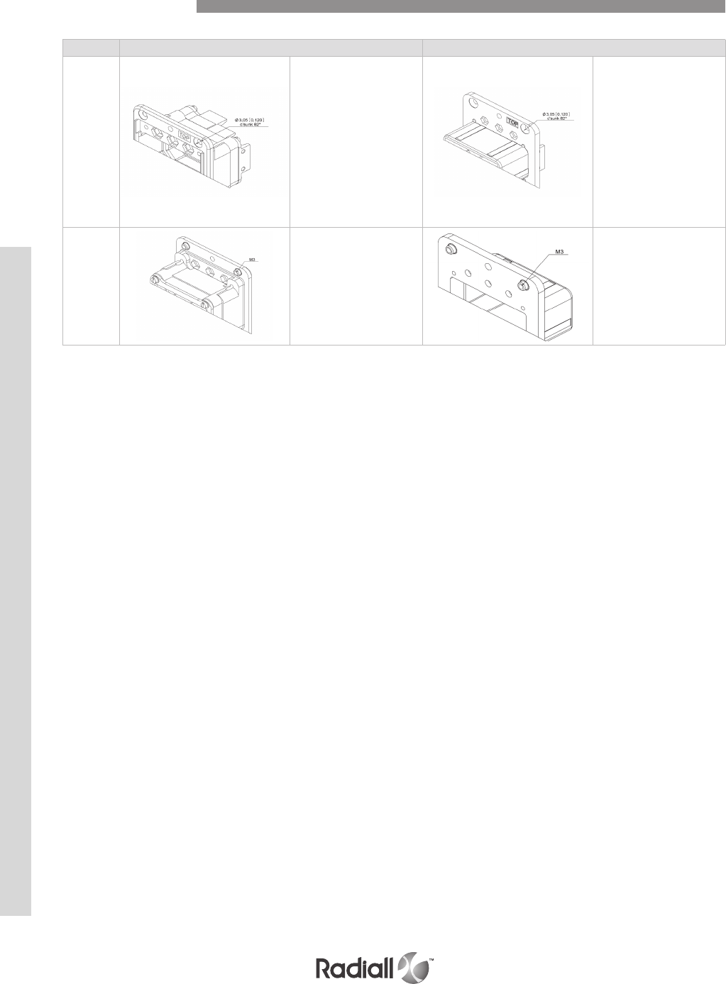
DSX SERIES
6-18
Our Most Important Connection is with You.™
Go online for data sheets & assembly instructions Visit www.radiall.com and enter the part number
Code Receptacle shell Plug shell
77
Sizes 1 & 2:
4 holes Ø3,05 (0.120) c’sunk
82° with attaching tabs for
RADIALL backshell
Size 3:
6 holes Ø3,05 (0.120) c’sunk
82° with attaching tabs for
RADIALL backshell
Not Available
for Size 4
Sizes 1 & 2:
4 holes Ø3,05 (0.120) c’sunk
82° with attaching tabs for
RADIALL backshell
Size 3:
6 holes Ø3,05 (0.120) c’sunk
82° with attaching tabs for
RADIALL backshell
Not Available
for Size 4
79
Sizes 1 & 2:
4 M3 clinch nuts
Size 3: 6 M3 clinch nuts
Size 4: 10 M3 clinch nuts
Sizes 1 & 2:
4 M3 clinch nuts
Size 3: 6 M3 clinch nuts
Size 4: 10 M3 clinch nuts
Modification Code

6-19
Our Most Important Connection is with You.™
Go online for data sheets & assembly instructions Visit www.radiall.com and enter the part number
POLARIZATION CODE TABLE
Position of polarization keys and posts.
Connectors are shown front side, with
“TOP” upwards.
Position coding
Dark area represents the polarizing post.
Clear position represents the key hole.
LEFT KEY
CENTER KEY
RIGHT KEY
RIGHT POLARIZING POST
CENTER POLARIZING POST
LEFT POLARIZING POST
Polarization
code
Receptacle shell Plug shell
Le
key
Center
key
Right
key
Le
post
Center
post
Right
post
00 //////
01 444111
02 443211
03 442311
04 441411
05 446511
06 445611
07 544116
08 543216
09 542316
10 541416
11 546516
12 545616
13 644115
14 643215
15 642315
16 641415
17 646515
18 645615
19 144114
20 143214
21 142314
22 141414
23 146514
24 145614
25 244113
26 243213
27 242313
28 241413
Polarization
code
Receptacle shell Plug shell
Le
key
Center
key
Right
key
Le
post
Center
post
Right
post
29 246513
30 245613
31 344112
32 343212
33 342312
34 341412
35 346512
36 345612
37 434121
38 433221
39 432321
40 431421
41 436521
42 435621
43 534126
44 533226
45 532326
46 531426
47 536526
48 535626
49 634125
50 633225
51 632325
52 631425
53 636525
54 635625
55 134124
56 133224
57 132324
Modification Code
DSX SERIES

DSX SERIES
6-20
Our Most Important Connection is with You.™
Go online for data sheets & assembly instructions Visit www.radiall.com and enter the part number
Polarization
code
Receptacle shell Plug shell
Le
key
Center
key
Right
key
Le
post
Center
post
Right
post
58 131424
59 136524
60 135624
61 234123
62 233223
63 232323
64 231423
65 236523
66 235623
67 334122
68 333222
69 332322
70 331422
71 336522
72 335622
73 424131
74 423231
75 422331
76 421431
77 426531
78 425631
79 524136
80 523236
81 522336
82 521436
83 526536
84 525636
85 624135
86 623235
87 622335
88 621435
89 626535
90 625635
91 124134
92 123234
93 122334
94 121434
95 126534
96 125634
97 224133
98 223233
99 222333
100 221433
101 226533
102 225633
103 324132
104 323232
105 322332
106 321432
107 326532
108 325632
109 414141
110 413241
111 412341
112 4 1 1 4 4 1
113 416541
114 415641
115 514146
116 513246
117 512346
118 511446
119 516546
120 515646
121 614145
122 613245
123 612345
124 611445
125 616545
126 615645
127 114144
128 113244
129 112344
130 111444
131 116544
132 115644
133 214143
134 213243
135 212343
136 211443
137 216543
Polarization
code
Receptacle shell Plug shell
Le
key
Center
key
Right
key
Le
post
Center
post
Right
post
138 215643
139 314142
140 313242
141 312342
142 311442
143 316542
144 315542
145 464151
146 463251
147 462351
148 461451
149 466551
150 465651
151 564156
152 563256
153 562356
154 561456
155 566556
156 565656
157 664155
158 663255
159 662355
160 661455
161 666555
162 665655
163 164154
164 163254
165 162354
166 161454
167 166554
168 165654
169 264153
170 263253
171 262353
172 261453
173 266553
174 265653
175 364152
176 363252
177 362352
178 361452
179 366552
180 365652
181 454161
182 453261
183 452361
184 451461
185 456561
186 455661
187 554166
188 553266
189 552366
190 551466
191 556566
192 5 5 5 6 6 6
193 654165
194 653265
195 652365
196 651465
197 656565
198 655665
199 154164
200 153264
201 152364
202 151464
203 156564
204 155664
205 254163
206 253263
207 252363
208 251463
209 256563
210 255663
211 354162
212 353262
213 352362
214 351462
215 356562
216 355662
Modification Code

6-21
Our Most Important Connection is with You.™
Go online for data sheets & assembly instructions Visit www.radiall.com and enter the part number
Contact
size AWG
Cross
section
(mm2)
Wire
outside dia
mm (inch)
Striping
length mm
(inch)
PIN SOCKET Crimping
tool Positionner SEL. Ins/Ext
tool
22
22
24
26
0.38
0.21
0.14
1.4 (0.055) 3.5 (0.138)
616200
(M39029/
11-144)
616300
(M39029/
12-148)
282281
(M22520/
2-01)
282970
(M22520/
2-23)
4
3
3
282885
(M81969/
1-01
22 reduced
crimp barrel
28
30
0.093
0.055 1.2 (0.047) 3.5 616201 616301 5
4
20HD
20
22
24
0.60
0.38
0.21
1.8 (0.071) 4.0 (0.157)
616210
(M39029/
11-145)
616310
(M39029/
12-149) 282971
(M22520/
2-08)
7
6
5282886
(M81969/
1-02)
20HD
reduced
crimp barrel
26
28
30
0.14
0.093
0.055
1.25 (0.049) 4.0 (0.157) 616211 616311
6
5
4
16
16
18
20
1.34
0.93
0.60
2.6 (0.236) 6.0 (0.236)
616230
(M39029/
11-146)
616330
(M39029/
12-150)
282291
(M22520/1-
01)
282972
(M22520/
1-02)
6
5
4282546
(M81969/
1-03)
16 reduced
crimp barrel
20
22
24
0.60
0.38
0.21
1.80 (0.071) 6.0 (0.236) 616231 616331 5
4
12
12
14
16
3.18
1.91
1.34
3.4 (0.134) 6.0 (0.236)
616240
(M39029/
11-147)
616340
(M39029/
11-151)
282579
(M22520/
1-11)
8
7
6
282547
(M81969/
28-02)
For cavity 5
12
14
3.18
1.91 3.4 (0.134)
8.0 (0.315)
616261 616361 282296
(DANIELS
M300BT) (1)
1
1282946
(M81969/
28-01)
10
8
5.0
9.0 5.7 (0.234) 616266 616366 282557 5
8
SIGNAL AND POWER CRIMP CONTACTS SIZES 22, 20HD, 16, 12 & 5
Contact
size AWG
Cross
section
(mm2)
Wire
outside dia
mm (inch)
Striping
length mm
(inch)
PIN SOCKET Crimping
tool Positionner SEL. Ins/Ext
tool
22
22
24
26
0.38
0.21
0.14
1.4 (0.055) 3.5 (0.138) 620280 620380 282281
(M22520/
2-01)
282970
(M22520/
2-23)
4
3
3
282885
(M81969/
1-01)
20HD
20
22
24
0.60
0.38
0.21
1.8 (0.071) 4.0 (0.157) 620290 620390
282971
(M22520/
2-08)
7
6
5
282886
(M81969/
1-02)
THERMOCOUPLE CONTACTS SIZES 22 & 20HD MADE OF CHROMEL
Contact
size AWG
Cross
section
(mm2)
Wire
outside dia
mm (inch)
Striping
length mm
(inch)
PIN SOCKET Crimping
tool Positionner SEL. Ins/Ext
tool
22
22
24
26
0.38
0.21
0.14
1.4 (0.055) 3.5 (0.138) 620281 620381 282281
(M22520/
2-01)
282970
(M22520/
2-23)
4
3
3
282885
(M81969/
1-01)
20HD
20
22
24
0.60
0.38
0.21
1.8 (0.071) 4.0 (0.157) 620291 620391
282971
(M22520/
2-08)
7
6
5
282886
(M81969/
1-02)
THERMOCOUPLE CONTACTS SIZES 22 & 20HD MADE OF ALUMEL
NOTE:
(1) Daniels WA27-309-EP air pressure tool with crimp setting 5 can also be used. Crimp setting 5 is not adjustable and must be set by the factory.
Contacts
DSX SERIES
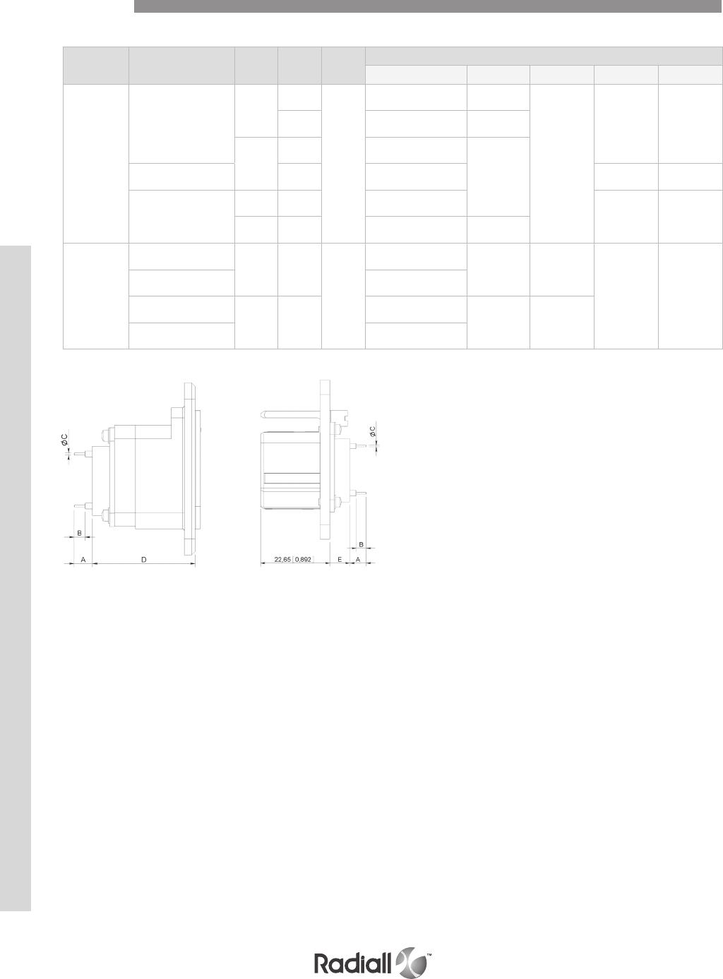
DSX SERIES
6-22
Our Most Important Connection is with You.™
Go online for data sheets & assembly instructions Visit www.radiall.com and enter the part number
Contact
size
Contact
arrangement Pin Socket Ext. Tool Dimensions mm (inch)
A B C D E
22
106
/
616379
282890
6.1/5.3 (0.240/0.209) 6.5 (0.256)
0.6 (0.023)
25.25/25.75
(0.994/1.013)
1.55/1.75
(0.061/0.069)
616303 14.4/13.6 (0.567/0.535) 9.4 (0.370)
616206*
616306* 5.9/6.7 (0.232/0.263)
3.8 (0.149)36C7 for pin contacts /0.82/0.10 (0.032/0.004) /7.85/7.44
(0.293/0.309)
36C7 for socket contacts
/616306 4/3.3 (0.157/0.130) 28.50/28.15
(1.122/1.108) /
/616303 11.72/11 (0.461/0.433) 9.4 (0.370)
20HD
40-45-57-32C2-32C4-
40C1 616216* /
282891
6.6/7.6 (0.259/0.299)
/0.8 (0.031)
31.25/31.75
(1.23/1.25)
7.45/7.75
(0.293/0.305)
67-33C4 6.3/7.3 (0.248/0.287)
40-45-57-32C2-32C4-
40C1 616223 616323*
3.5/4.3 (0.138/0.169)
3.2 (0.126) 0.6 (0.023)
67-33C4 3.2/4 (0.126/0.157)
SIZES 22 & 20HD PC TAIL CONTACTS
NOTE:
* Connectors delivered in the “Y” termination style will be fitted with contacts marked by “*” (see above table). If another style of pc tail contact is
desired, use termination style “x” when ordering the connector and order contacts separately.
Contacts
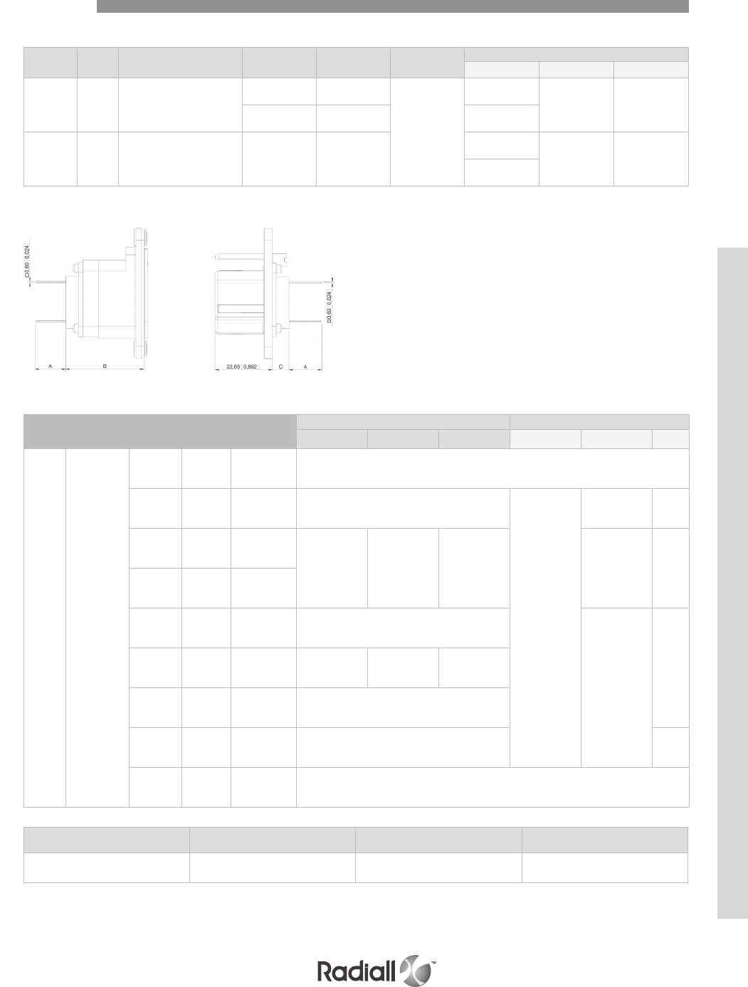
6-23
Our Most Important Connection is with You.™
Go online for data sheets & assembly instructions Visit www.radiall.com and enter the part number
Contact
size AWG Contact arrangement Pin Socket Ins. tool Dimensions
ABC
22
26
28
30
106
610203
(2 wrap levels)
610303
(2 wrap levels)
282527
10/11
(0.393/0.433) 25.25/25.75
(0.994/1.013)
1.55/1.75
(0.061/0.069)
610204
(3 wrap levels)
610304
(3 wrap levels)
12.5/13.5
(0.492/0.531)
20
26
28
30
40-45-57-32C2-
32C4-40C1-67-33C4
610214
(2 wrap levels)
610314
(2 wrap levels)
10.3/11.3
(0.405/0.445) 31.25/31.75
(1.203/1.250)
7.45/7.75
(0.293/0.305)
9.85/10.95
(0.387/0.431)
Part number 616004 – 616006 - 616007 616009 – 616100 – 616103001
616106 - 616102001
616003 – 616005
616107001
Dielectric withstanding voltage
at sea level (V rms) 1000 1500 2500
SIZES 22 & 20HD WIRE WRAP CONTACTS
COAXIAL CRIMP CONTACTS SIZE 1 (design as per MS3168-3169 specifications)
NOTE:
(1) For other cable, please contact Radiall.
Contact
size
Contact
arrangement
Cable
(1) Pin Socket Center contact Outer body
Crimping tool Positioner SEL. Crimping tool Die Hex
1MC2
UT 141
RG 402 616005 /Solder contact
RG 58
RG 141
KX 15
616006
right angle /Solder contact
282293
(M22520/5-01)
282246
(M22520/5-05) A
RG 213
KX 4 /616102001
282291
(M22520/1-01)
282997
(M22520/1-13) 8282247
(M22520/5-61) A
RG 214
RG 225
/
616003
616103001
/
RG 142 616007
right angle /Solder contact
282246
(M22520/5-05)
A
RG 142
RG 223 /616107001 282291
(22520/1-01)
282997
(M22520/1-13) 7
RG 174
KX 22 /616100 Solder contact
RD 316 616004
right angle /Solder contact B
/616009 /SMA Termination
Contacts
DSX SERIES
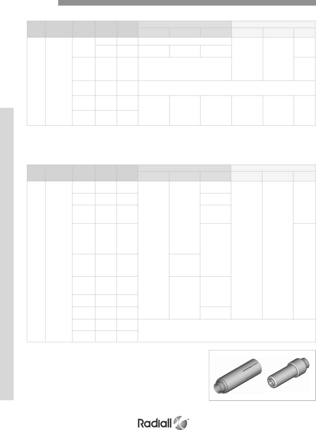
DSX SERIES
6-24
Our Most Important Connection is with You.™
Go online for data sheets & assembly instructions Visit www.radiall.com and enter the part number
Contact
size
Contact
arrangement
Cable
(1) Pin Socket
Center contact Outer body
Crimping tool Positioner SEL. Crimping tool Die Hex
3MC3
RG 142
RG 223
616013 /Solder
282293
(M22520/5-01)
282246
(M22520/5-05)
A
/616113 282291
(M22520/1-01)
282997
(M22520/5-05) 7
RG 316
616015
Right
angle
(1)
/solder B
UT 141
RG 402 616014 /solder
RG 214
RG 225 /616111 282291
(M22520/1-01)
282997
(M22520/5-05) 8282293
(M22520/5-01)
282247
(M22520/5-61) A
RG 213
KX 4 /616112
COAXIAL CRIMP CONTACTS SIZE 3
The following contacts have to be fitted with a sealing boot when used in DSX E connectors (see page
6-29). Coaxial cavities without any contact can be fitted with sealing plugs when used in DSX E connectors.
Contact
size
Contact
arrangement
Cable
(1)
Pin
(See notes 3&4)
Socket
(See notes 3&4)
Center contact Outer body
Crimping tool Positioner SEL. Crimping tool Die Hex
5
32C2
32T2
33C4
33T4
36C7
36T7
40C1
40T1
RG 58
KX 15 616120 616020
282281
(M22520/2-01)
282974
6
282293
(M22520/5-01)
282246
(M22520/5-05)
A
RG 141 616120 616020 8
RG 142
RG 223
KX 23
616121 616021 8
RG 179
RG 188
RG 174
RG316
KX 22
616122 616022
7
B
RG 179
RG 187 /616022002
282550
DANIELS
K345
RG 196
RG 178
KX 21
616123 616023
282974
6
RG 195
RG 180 616124 616024
RG 316
DS 616163 616026 7
UT .085 616125 /
solder
UT .141 616128 616028
NOTES:
(1) For other cable, please contact Radiall
(2) Dielectric withstanding voltage at sea level: 1500 V rms. Except 1000 V rms for 616015
(3) Dielectric withstanding voltage at sea level: 750 V rms
(4) Extraction tool: 282946 (M81969/28-01)
Contacts
COAXIAL CRIMP CONTACTS SIZE 5 (design as per MS3172 specifications)

6-25
Our Most Important Connection is with You.™
Go online for data sheets & assembly instructions Visit www.radiall.com and enter the part number
COAXIAL CRIMP CONTACTS SIZE 7
COAXIAL CRIMP CONTACTS SIZE 15
Contact
size Contact
arrangement Cable
(1)
Pin
(See notes 2&3)
Socket
(See notes 2&3)
Center contact Outer body
Crimping tool Positioner SEL. Crimping tool Die Hex
7MC3
RG 58
RG 141
KX 15
610120 /
solder
282293
(M22520/5-01)
282246
(M22520/5-05)
A
RG 174
RG 316
KX 22
RG 188
610126 / B
RG 58
KX 15 /616030
282281
(M22520/2-01
282550
(DANIELS
K345)
6 A
RG 141 /616030 8 A
RG 142
RG 223
KX 23
/616031 8 A
RG 174
RG 316
KX 22
/616032 7 B
Contact
size
Contact
arrangement
Cable
(1)
Pin
(See notes 2&3)
Socket
(See notes 2&3)
Center contact Outer body
Crimping tool Positioner SEL. Crimping tool Die Hex
15
D8
26
67
32C4
32T4
33C4
33T4
RG 316
RG 179 616154
618050
282281
(M22520/2-01) 282555 2
282292
(M22520/4-01) 282556 /
KX 22
DS 616150
KX 21
DS 616151 618053
RG 178
KX 21 616153 618054
Contact
size
Contact
arrangement
Cable
(1)
Pin
(See notes 2&3)
Socket
(See notes 2&3)
Center contact Outer body
Crimping tool Positioner SEL. Crimping tool Die Hex
9
C8
T8
32C4
32T4
RG 58
KX 15 616140 616040
282281
(M22520/2-01) 282974
6
282293
(M22520/5-01)
282246
(M22520/5-05)
A
RG 141 8
RG 142
RG 223
KX 23
616141 616041 8
RG 174
RG 179
RG 188
RG 316
KX 22
616142 616042 7
B
RG 178
RG196
KX 21
616143 616043 6
RG 180
RG 195 616144 616044 6
COAXIAL CRIMP CONTACTS SIZE 9
NOTES:
(1) For other cable, please contact Radiall
(2) Dielectric withstanding voltage at sea level: 750 V rms
(3) Extraction tool: 282946 (M81969/28-01)
(4) Dielectric withstanding voltage at sea level: 350 V rms
Contacts
Add 001 at the end of each part number pin or socket to order environmental size 9 coax contacts. Coaxial
cavities without any contact can be fitted with sealing plugs when used in DSX E connectors.
DSX SERIES
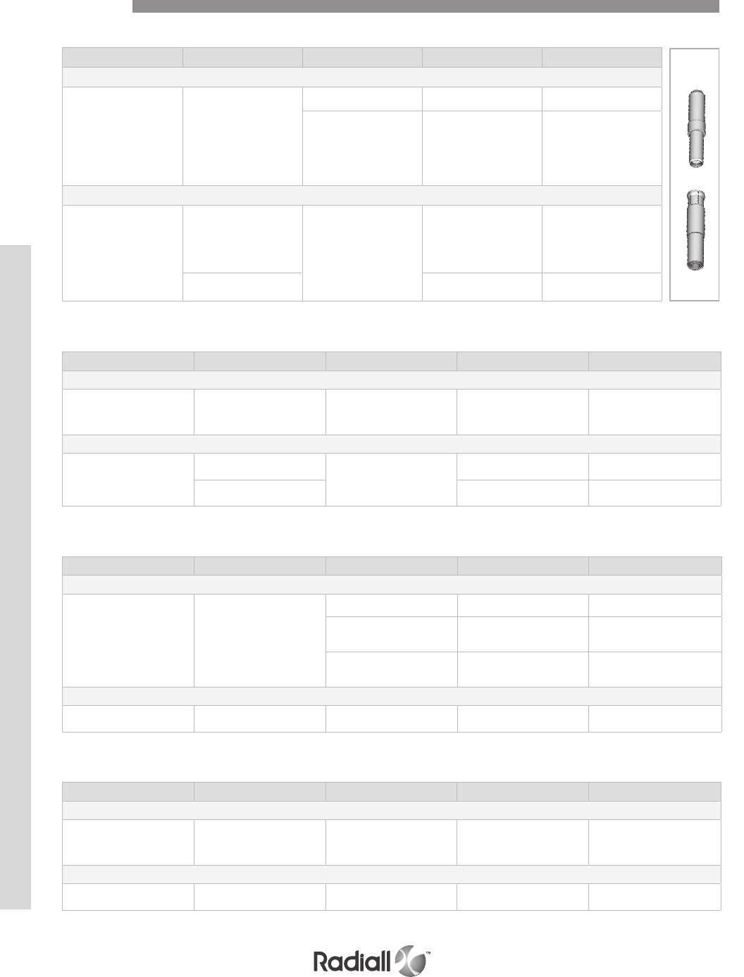
DSX SERIES
6-26
Our Most Important Connection is with You.™
Go online for data sheets & assembly instructions Visit www.radiall.com and enter the part number
CONCENTRIC TWINAX CRIMP CONTACTS SIZE 5 (design as per 17B9E4005 specifications)
Contact size Contact arrangement Cable Pin Socket
The following contacts have to be installed in the non environmental inserts
5
32C3
32T2
40C1
40T1
36C7
36T7
33C4
33T4
MIL-C-17/176-00002 616195001 616095001
PAN 6421 616195005 616095005
The following contacts have to be installed in the environmental inserts
5
32C3
32T2
40C1
40T1
33C4
33T4
MIL-C-17/176-00002
616195009 616095009
36C7
36T7 616195012 /
CONCENTRIC TWINAX CRIMP CONTACTS SIZE 9 (design as per 17B9E4005 specifications)
Contact size Contact arrangement Cable Pin Socket
The following contacts have to be installed in the non environmental inserts
9
C8
T8
32C4
32T4
MIL-C-17/176-00002 616196003 616096003
The following contacts have to be installed in the environmental inserts
9
C8
T8 MIL-C-17/176-00002
/616096006
32C4
32T4 616196004 616096004
TRIAX CRIMP CONTACTS SIZE 5
Contact size Contact arrangement Cable Pin Socket
The following contacts have to be installed in the non environmental inserts
5
33C4
33T4
32C2
32T2
40C1
40T1
36C7
36T7
RGX 179 616195004 616095004
ST5M 1323-1 616195007 616095007
HS4863-1
HS4863-2 616195000 616095000
The following contacts have to be installed in the environmental inserts
536C7
36T7 RGX 179 /616095010
TRIAX CRIMP CONTACTS SIZE 9
Contact size Contact arrangement Cable Pin Socket
The following contacts have to be installed in the non environmental inserts
9
C8
T8
32C4
32T4
RGX 179 616196001 616096001
The following contacts have to be installed in the environmental inserts
932C4
32T4 RGX 179 /616096002
Contacts
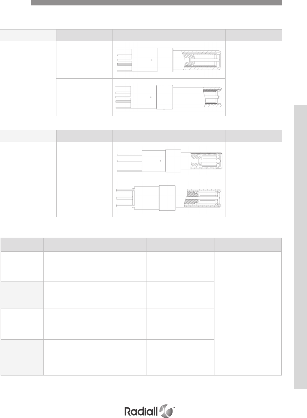
6-27
Our Most Important Connection is with You.™
Go online for data sheets & assembly instructions Visit www.radiall.com and enter the part number
TRIAX CONTACTS WITH PC TAIL SIZE 5
Contact type Part number Contact drawing Rear extension from the
insert mm (inch)
Pin
616195003 32C2, 32T2, 33C4,33T4
40C1, & 40T1 =
3.2/4.0 (0.125/0.158)
36C7 & 36T7 =
5.40/6.10 (0.212/0.240)
616195008
Contact type Part number Contact drawing Rear extension from the
insert mm (inch)
Pin
616196005
C8 & T8 =
1.30/2.15 (0.051/0.085)
32C4 & 32T4 =
6.45/7.30 (0.253/0.288)
616196007
C8 & T8 = 0
32C4 & 32T4 =
3.70/4.35 (0.145/0.172)
Contacts
The contacts shown in the table below are rear release rear removable contacts
Wire Type Part number
(non environmental)
Part number
(environmental) Ins/Ext Tool
ABS1503KD24
(110 Ω)
Pin 620175010 620175011
282549001
(M81969/28.03
or M81969/14.06)
Socket 620075010 620075011
THERMAX
956S-4T200
GORE RCN8422
(110 Ω)
Pin 620179002 620179001
Socket 620079002 620079001
TENSOLITE
NF24Q100 (100 Ω)
Pin 620175050 620175051
Socket 620075050 620075051
TENSOLITE
NF26Q100
JSFY 18
Pin 620175021 620175020
Socket 620075021 620075020
SIZE 8 QUADRAX CONTACTS
DSX SERIES
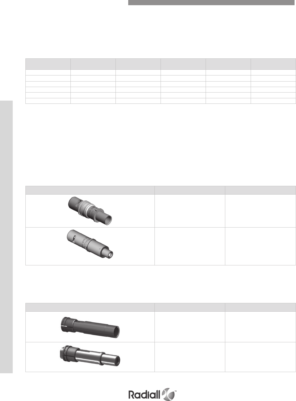
DSX SERIES
6-28
Our Most Important Connection is with You.™
Go online for data sheets & assembly instructions Visit www.radiall.com and enter the part number
MIL-PRF-29504 fiber optic termini were developed several decades ago and are described into
several MIL standard documents. They fit into standard electrical cavities and do not require
specific inserts. They can replace MIL-PRF-29504/10 pin and MIL-PRF-29504/11 socket termini.
Radiall offers you a unique solution to equip your DSX connectors with EN4531 fiber optic contacts.
This solution offers the following characteristics and advantages:
- It turns a ARINC 404 size 5 or size 8 cavity into a fiber optic link
- It accepts any EN4531-101 fiber optic contacts
ACCESSORIES
Size 12 MIL-T-29504 contacts can be available upon request, please contact your Radiall sales representative.
Note that Radiall can support you with your cable and harness assemblies. Please contact your sales representative.
MIL-PRF-29504 CONTACTS
Pin contact
part number
Socket contact
part number Contact size Fiber diameter (µm) Cable diameter (mm) Ferrule material
F724 005 000 F724 104 000 16 125 1.5 Ceramic
F724 011 000 F724 111 000 16 125 1.8 Ceramic
F724 009 000 F724 109 000 16 125 2Ceramic
F724 002 000 F724 101 000 16 140 1.5 Ceramic
F724 041 000 F724 140 000 16 230 2Metallic
F724 007 000 F724 107 000 16 280 1.6 Ceramic
Part number Description
616925001 Pin adapter for #5 cavity
616925002 Socket adapter for #5 cavity
EN4531-101 adapter for size 5 cavity is available for DSX F connectors with inserts 33C4 and 81C3 only,
see DSX F connectors page 6-41.
EN4531-101 (ABS 1379) ADAPTER FOR SIZE 5 CAVITY
Part number Description
620946005 Pin quadrax adapter
for EN4531 contact
620946006 Socket quadrax adapter
for EN4531 contact
EN4531-101 (ABS 1379) ADAPTER FOR QUADRAX SIZE 8 CAVITY
Fiber Optic Contacts and Accessories
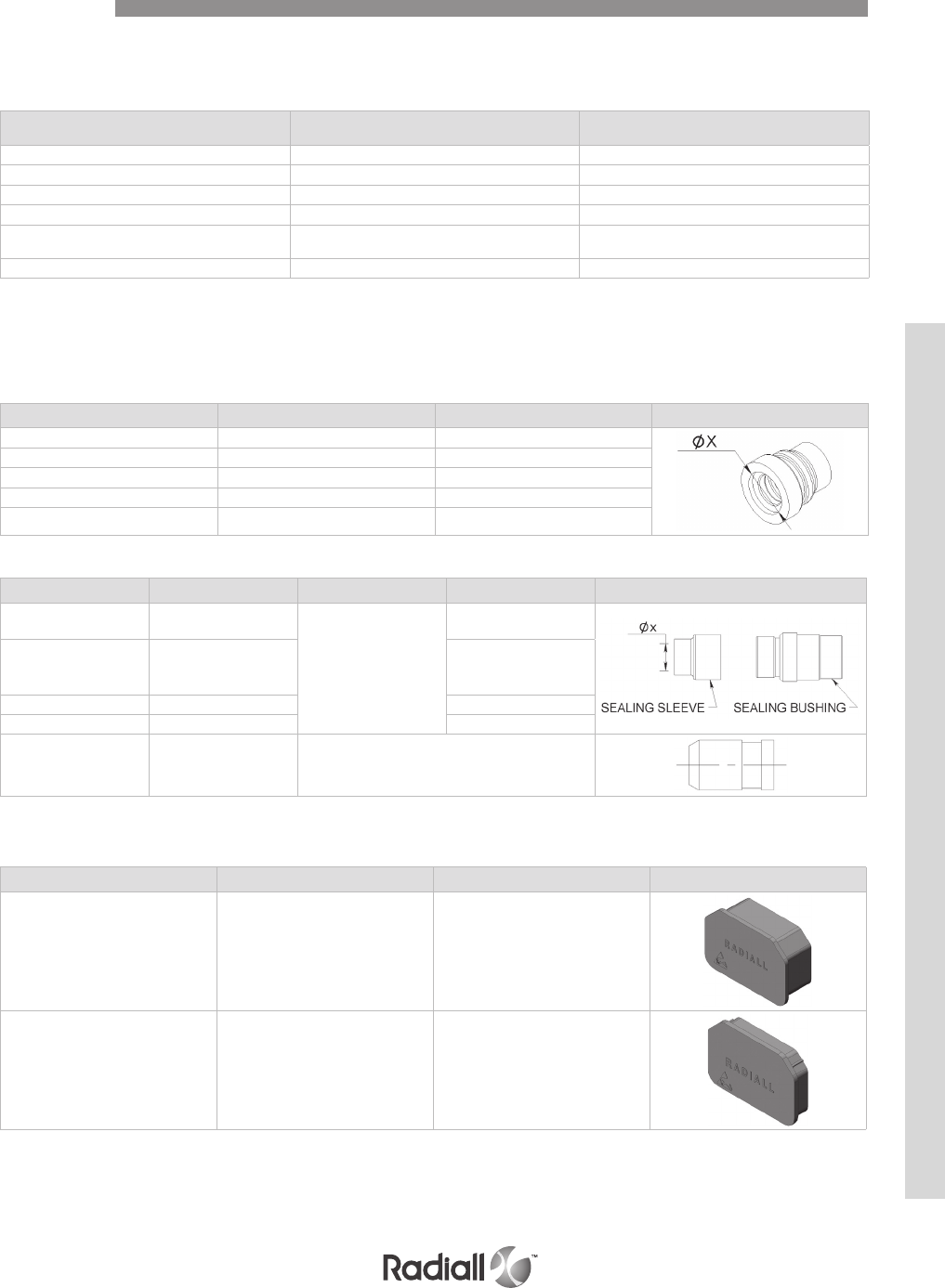
6-29
Our Most Important Connection is with You.™
Go online for data sheets & assembly instructions Visit www.radiall.com and enter the part number
SEALING BOOTS
Table 1
Cable X dia. mm (inch) Part number Drawing
RG58, RG142 4.3 (0.169) 92505490
RG 174 2 (0.079) 92505470
RG 178 1.4 (0.055) 92505460
RG180 3.1 (0.122) 92505480
/ 0 92505450
Table 2
Cable X dia. mm (inch) Sealing bushing Sealing sleeve Part number
RG58, RG141, RG142,
RG223, KX15, KX23 4.7 (0.185)
92505590
92505591
RG174, RG179, RG187,
RG188, RG316, KX22,
UT.085
2.15 (0.085) 92505593
RG178, RG196 1.5 (0.059) 92505594
RG180, RG195, UT.141 3.05 (0.120) 92505592
/ 0 616914010 (3)
NOTES:
(1) 616923 is made of aluminium and is nickel plated
(2) 616917 and 616915 provide interfacial sealing on class T connectors
(3) 616914010 is made of PTFE
SEALING PLUGS AND FILLER PLUGS
Contact size Sealing plugs Filler plugs
Size 22 616910 620920
Size 20HD 616911 610941
Size 16 616912 620922
Size 12 616913 616923
Size 5 See notes 620924, 616923 (1) or 616917 (2) for pin contact cavity
620925 for socket contact cavity
Size 9 See notes 616915 (2)
DUST CAPS
Conductive (black) Non Conductive (red) Drawing
Plug 610804 610803
Receptacle 610806 610805
Accessories
Filler plugs are used in non environmental connectors and sealing
plugs are used in environmental connectors and conform to MS27488
The sealing boots in table 1 are to be used in all inserts with size 5 contact cavities except 36C7
and 36T7 inserts which use the sealing bushing plus one in the sealing sleeves in table 2.
Conductive dust caps are made of thermoplastic and non conductive dust caps are made of polyethylene.
DSX SERIES
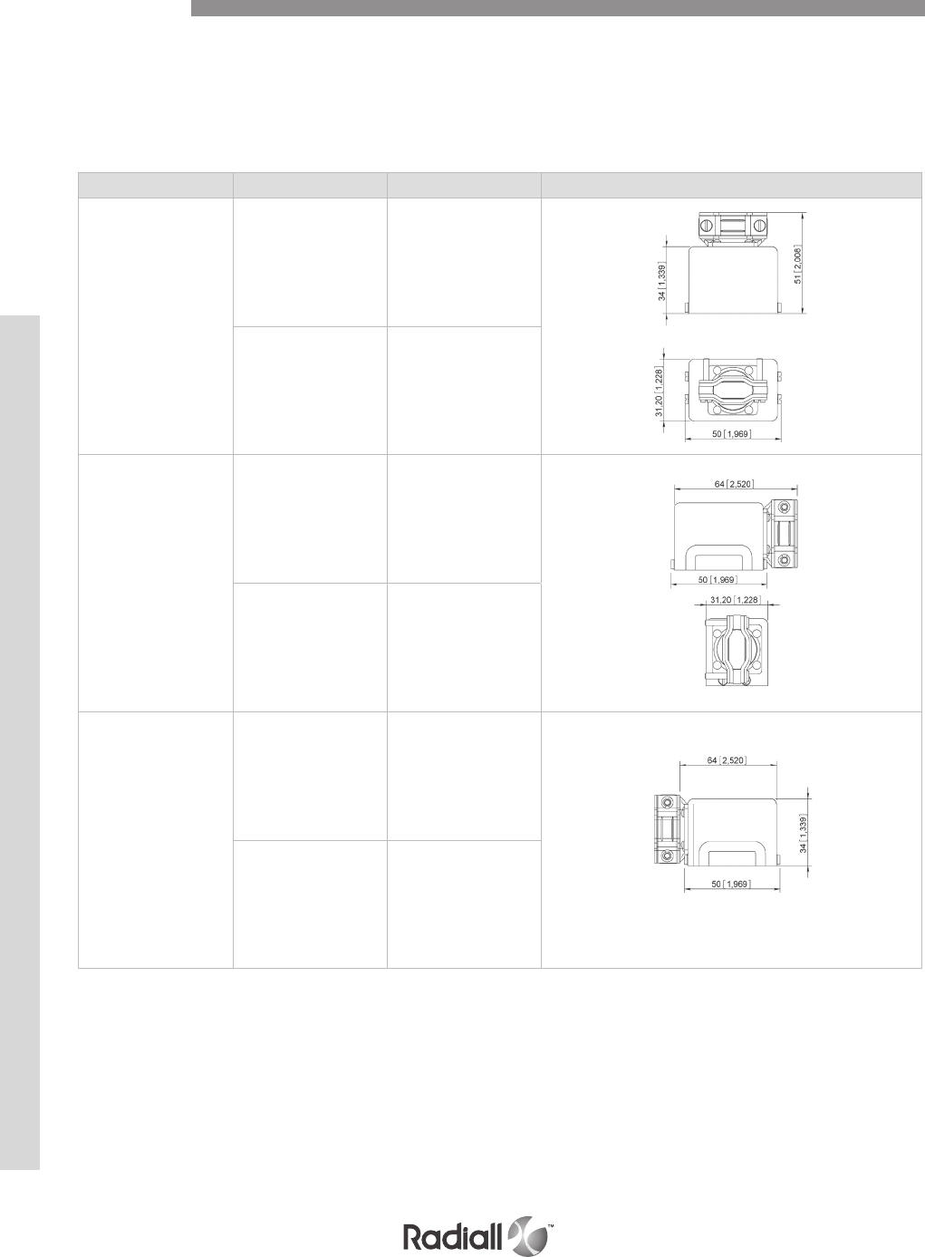
DSX SERIES
6-30
Our Most Important Connection is with You.™
Go online for data sheets & assembly instructions Visit www.radiall.com and enter the part number
BACKSHELLS
Entry type Plating Part number Drawing
Top entry
Yellow anodized 610902
Nickel 610906
Right entry
Yellow anodized 610900
Nickel 610910
Left entry
Yellow anodized 610901
Nickel 610911
Accessories
The following backshells are only for use with SAE AS81659 and ARINC 404 shell type B connectors for
the following modification codes 02 - 04 - 17 - 19 - 22 - 36 - 61 - 67 and 77.
Backshells do not ensure EMI functions and cannot be installed on size 4 connectors as there is
limited access to screws.

6-31
Our Most Important Connection is with You.™
Go online for data sheets & assembly instructions Visit www.radiall.com and enter the part number
SHELL SIZE 1 NON ENVIRONMENTAL (without grommet seal)
SHELL SIZE 1 ENVIRONMENTAL (with grommet seal)
Max dimension
mm (inch)
All crimp contact
arrangements except
106
Contact arrangement
106
Arrangements with
coax contacts size 1 & 3
Contact arrangement
36C7 & 36T7
Arrangements with
coax contacts size 5 & 9
except 36C7
A 32 (1.260) 25.8 (1.016) 26.85 (1.057) 28.5 (1.122) 37.42 (1.473)
B 7.9 (0.311) 1.9 (0.075) 3 (0.118) 7.85 (0.309) 13.5 (0.531)
Max dimension
mm (inch)
All crimp contact arrangements except
MC2 – MC3 - 106
Contact arrangement
106
Contact arrangement
36C7 & 36T7
A 38.5 (1.516) 33.5 (1.319) 39.05(1.537)
B 14.2 (0.559) 9.5 (0.374) 18.55 (.730)
Important Note: Only 4mm of space is available on the modification code selection
Dimensions
DSX SERIES
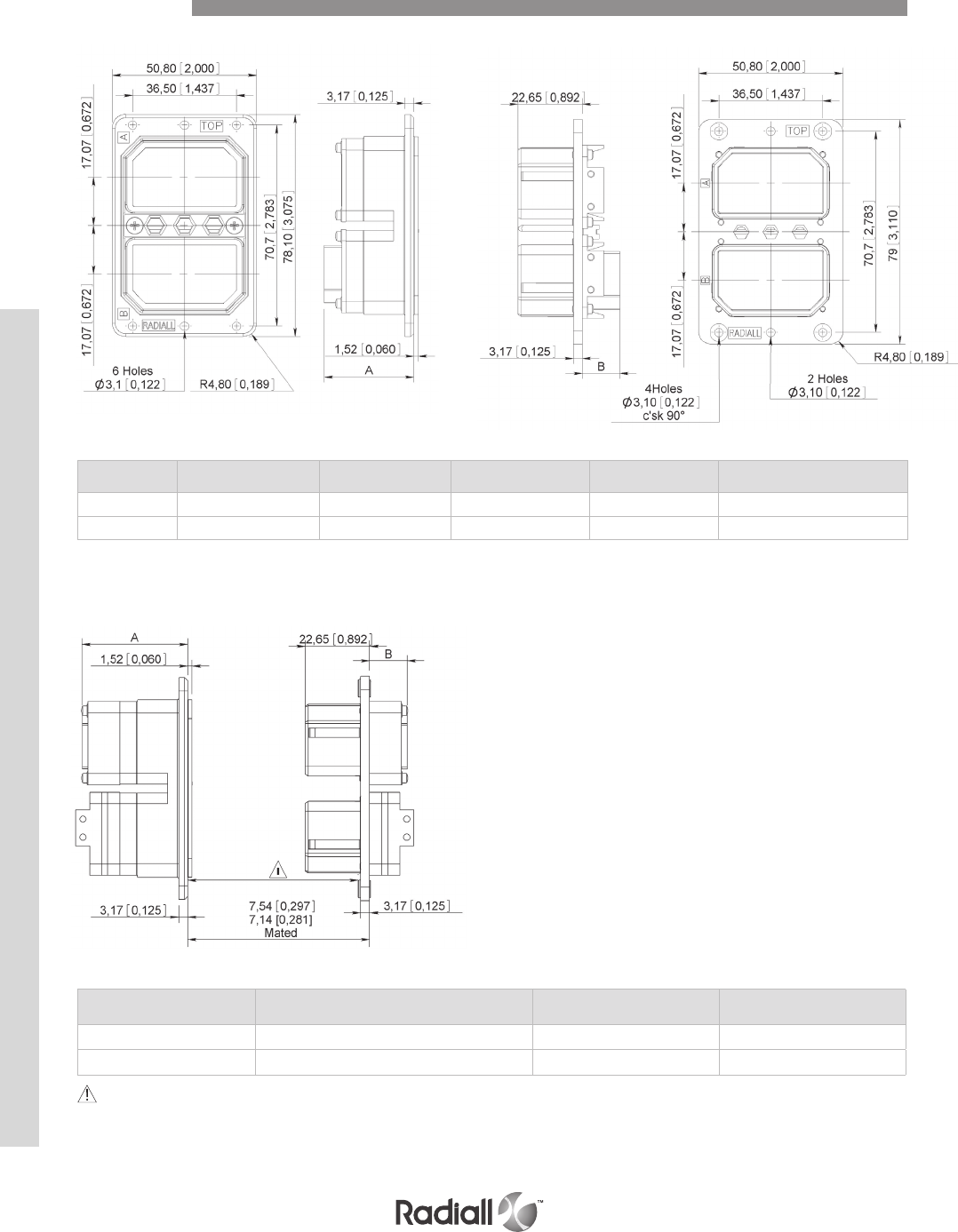
DSX SERIES
6-32
Our Most Important Connection is with You.™
Go online for data sheets & assembly instructions Visit www.radiall.com and enter the part number
SHELL SIZE 2 NON ENVIRONMENTAL (without grommet seal)
SHELL SIZE 2 ENVIRONMENTAL (with grommet seal)
Max dimension
mm (inch)
All crimp contact
arrangements except 106
Contact arrangement
106
Arrangements with coax
contacts size 1 & 3
Contact arrangement
36C7 & 36T7
Arrangements with coax contacts
size 5 & 9 except 36C7
A32 (1.260) 25.8 (1.016) 26.85 (1.057) 28.5 (1.122) 37.42 (1.473)
B7.9 (0.311) 1.9 (0.075) 3 (0.118) 7.85 (0.309) 13.5 (0.531)
Max dimension
mm (inch)
All crimp contact arrangements
except MC2 – MC3 - 106
Contact arrangement
106
Contact arrangement
36C7 & 36T7
A38.5 (1.516) 33.5 (1.319) 39.05(1.537)
B14.2 (0.559) 9.5 (0.374) 18.55 (.730)
Important Note: Only 4mm of space is available on the modification code selection
Dimensions
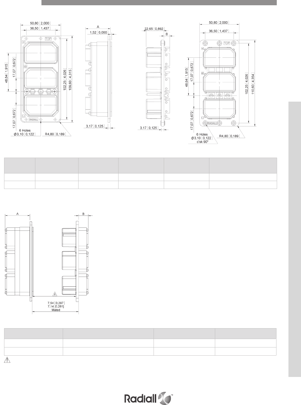
6-33
Our Most Important Connection is with You.™
Go online for data sheets & assembly instructions Visit www.radiall.com and enter the part number
SHELL SIZE 3 ENVIRONMENTAL (with grommet seal)
Max dimension
mm (inch)
All crimp contact
arrangements except
106
Contact arrangement
106
Arrangements with coax
contacts size 1 & 3
Contact arrangement
36C7 & 36T7
Arrangements with coax contacts
size 5 & 9 except 36C7
A32 (1.260) 25.8 (1.016) 26.85 (1.057) 28.5 (1.122) 37.42 (1.473)
B7.9 (0.311) 1.9 (0.075) 3 (0.118) 7.85 (0.309) 13.5 (0.531)
Max dimension
mm (inch)
All crimp contact arrangements except
MC2 – MC3 - 106
Contact arrangement
106
Contact arrangement
36C7 & 36T7
A38.5 (1.516) 33.5 (1.319) 39.05(1.537)
B14.2 (0.559) 9.5 (0.374) 18.55 (.730)
Important Note: Only 4mm of space is available on the modification code selection
Dimensions
SHELL SIZE 3 NON ENVIRONMENTAL (without grommet seal)
DSX SERIES
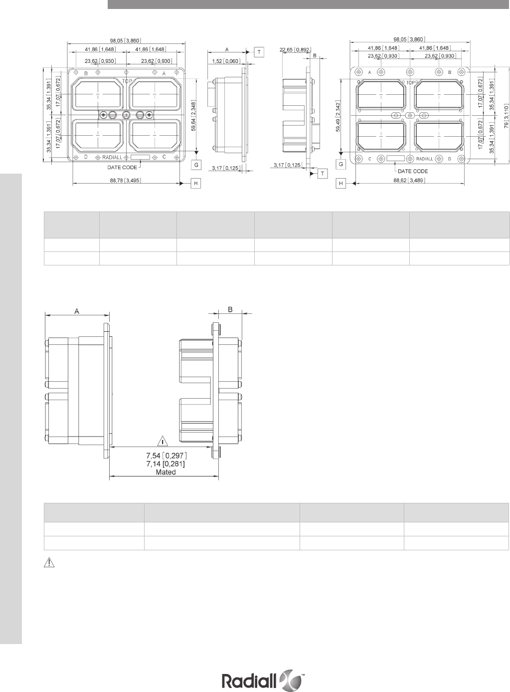
DSX SERIES
6-34
Our Most Important Connection is with You.™
Go online for data sheets & assembly instructions Visit www.radiall.com and enter the part number
SHELL SIZE 4 NON ENVIRONMENTAL (without grommet seal)
SHELL SIZE 4 ENVIRONMENTAL (with grommet seal)
Max dimension
mm (inch)
All crimp contact
arrangements except
106
Contact arrangement
106
Arrangements with coax
contacts size 1 & 3
Contact arrangement
36C7 & 36T7
Arrangements with coax
contacts size 5 & 9 except 36C7
A32 (1.260) 25.8 (1.016) 26.85 (1.057) 28.5 (1.122) 37.42 (1.473)
B7.9 (0.311) 1.9 (0.075) 3 (0.118) 7.85 (0.309) 13.5 (0.531)
Max dimension
mm (inch)
All crimp contact arrangements except
MC2 – MC3 - 106
Contact arrangement
106
Contact arrangement
36C7 & 36T7
A38.5 (1.516) 33.5 (1.319) 39.05(1.537)
B14.2 (0.559) 9.5 (0.374) 18.55 (.730)
Important Note: Only 4mm of space is available on the modification code selection
Dimensions
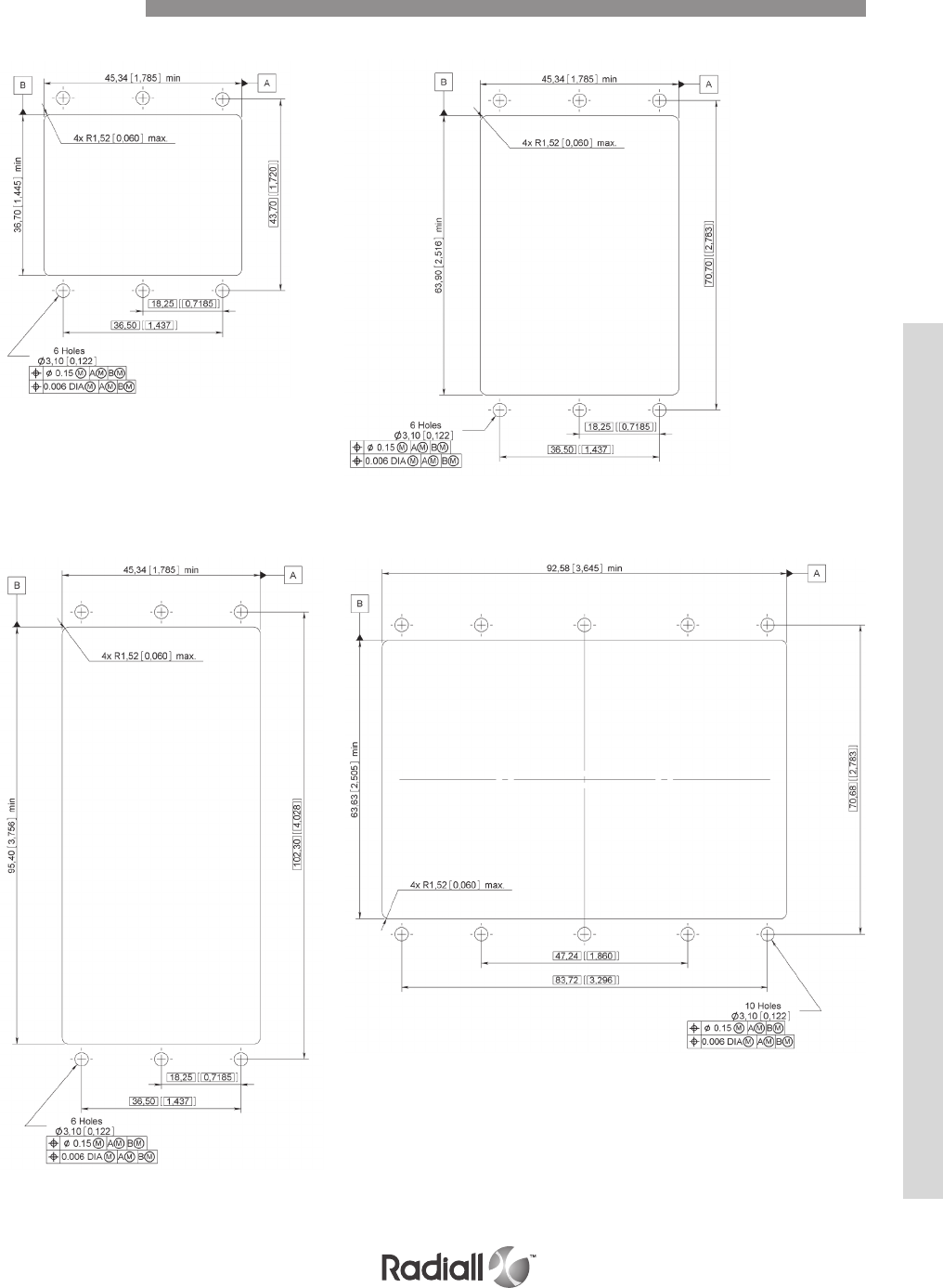
6-35
Our Most Important Connection is with You.™
Go online for data sheets & assembly instructions Visit www.radiall.com and enter the part number
SHELL SIZE 1
SHELL SIZE 3
SHELL SIZE 2
SHELL SIZE 4
Panel Cut Outs
DSX SERIES

DSX SERIES
6-36
Our Most Important Connection is with You.™
Go online for data sheets & assembly instructions Visit www.radiall.com and enter the part number
FROM RADIALL TO MILITARY P/N
Radiall part number Mil part number
616200 M3902911144
616210 M3902911145
616230 M3902911146
616240 M3902911147
616300 M3902912148
616310 M3902912149
616330 M3902912150
616340 M3902912151
616910 MS2748822
616911 MS2748820
616912 MS2748816
616913 MS2748812
DSXE1PS106P73 M8165929A20041
DSXE1PS26S73 M8165929A20002
DSXE1PS32C2S73 M8165929A20140
DSXE1PS32C4S73 M8165929A20150
DSXE1PS33C4S73 M8165929A20104
DSXE1PS40C1S73 M8165929A20142
DSXE1PS40S73 M8165929A20010
DSXE1PS45S73 M8165929A20018
DSXE1PS57P73 M8165929A20025
DSXE1PS57S73 M8165929A20026
DSXE1PS67S73 M8165929A20034
DSXE1PSD8S73 M8165929A20084
DSXE1PXC8S73 M8165929A20136
DSXE1R32C4P00 M8165931A20149
DSXE1R33C4P00 M8165931A20103
DSXE1RS106S00 M8165931A20042
DSXE1RS26P00 M8165931A20001
DSXE1RS32C2P00 M8165931A20139
DSXE1RS40C1P00 M8165931A20141
DSXE1RS40P00 M8165931A20009
DSXE1RS45P00 M8165931A20017
DSXE1RS57P00 M8165931A20025
DSXE1RS57S00 M8165931A20026
DSXE1RS67P00 M8165931A20035
DSXE1RSD8P00 M8165931A20083
DSXE2PS106PS106P73 M8165933A20043
DSXE2PS106PS26S73 M8165933A20058
DSXE2PS106PS67S73 M8165933A20090
DSXE2PS106PXC8S73 M8165933A20088
DSXE2PS26SS106P73 M8165933A20060
DSXE2PS26SS26S73 M8165933A20004
DSXE2PS32C2SS106P73 M8165933A20130
DSXE2PS32C2SS40C1S73 M8165933A20122
DSXE2PS32C2SS45S73 M8165933A20124
DSXE2PS32C2SS57S73 M8165933A20126
DSXE2PS32C2SS67S73 M8165933A20128
DSXE2PS32C4SS106P73 M8165933A20152
Radiall part number Mil part number
DSXE2PS32C4SXC8S73 M8165933A20160
DSXE2PS33C4SS106P73 M8165933A20106
DSXE2PS33C4SXC8S73 M8165933A20108
DSXE2PS40C1SS40C1S73 M8165933A20132
DSXE2PS40SS40S73 M8165933A20012
DSXE2PS45SS45S73 M8165933A20020
DSXE2PS57SS106P73 M8165933A20134
DSXE2PS57SS26S73 M8165933A20148
DSXE2PS57SS57S73 M8165933A20028
DSXE2PS67SS106P73 M8165933A20072
DSXE2PS67SS67S73 M8165933A20036
DSXE2PXC8SS106P73 M8165933A20118
DSXE2PXC8SS32C4S73 M8165933A20156
DSXE2PXC8SS57S73 M8165933A20146
DSXE2PXMC2SS40C1S73 M8165933A20110
DSXE2PXMC2SS57S73 M8165933A20112
DSXE2PXMC3SS106P73 M8165933A20116
DSXE2PXMC3SS67S73 M8165933A20114
DSXE2RS106SS106S00 M8165935A20044
DSXE2RS106SS26P00 M8165935A20057
DSXE2RS106SS67P00 M8165935A20089
DSXE2RS106SXC8P00 M8165935A20087
DSXE2RS26PS106S00 M8165935A20059
DSXE2RS26PS26P00 M8165935A20003
DSXE2RS32C2PS106S00 M8165935A20129
DSXE2RS32C2PS40C1P00 M8165935A20121
DSXE2RS32C2PS45P00 M8165935A20123
DSXE2RS32C2PS57P00 M8165935A20125
DSXE2RS32C2PS67P00 M8165935A20127
DSXE2RS32C4PS106S00 M8165935A20151
DSXE2RS32C4PXC8P00 M8165935A20159
DSXE2RS33C4PS106S00** M8165935A20105
DSXE2RS33C4PXC8P00** M8165935A20107
DSXE2RS40C1PS40C1P00 M8165935A20131
DSXE2RS40PS40P00 M8165935A20011
DSXE2RS45PS45P00 M8165935A20019
DSXE2RS57PS106S00 M8165935A20133
DSXE2RS57PS26P00 M8165935A20147
DSXE2RS57PS57P00 M8165935A20027
DSXE2RS67PS106S00 M8165935A20071
DSXE2RS67PS67P00 M8165935A20035
DSXE2RXC8PS106S00 M8165935A20117
DSXE2RXC8PS32C4P00 M8165935A20155
DSXE2RXC8PS57P00 M8165935A20145
DSXE2RXMC2PS40C1P00 M8165935A20109
DSXE2RXMC2PS57P00 M8165935A20111
DSXE2RXMC3PS106S00 M8165935A20115
DSXE2RXMC3PS67P00 M8165935A20113
DSXE3PS106PS106PS106P73 M8165937A20045
Cross Reference

6-37
Our Most Important Connection is with You.™
Go online for data sheets & assembly instructions Visit www.radiall.com and enter the part number
Radiall part number Mil part number
DSXE3PS106PS106PS32C4S73 M8165937A20158
DSXE3PS106PS106PS67S73 M8165937A20092
DSXE3PS26SS26SS26S73 M8165937A20006
DSXE3PS40SS40SS40S73 M8165937A20014
DSXE3PS45SS45SS45S73 M8165937A20022
DSXE3PS57SS57SS57S73 M8165937A20030
DSXE3PS67SS106PS67S73 M8165937A20080
DSXE3PS67SS67SS106P73 M8165937A20076
DSXE3PS67SS67SS67S73 M8165937A20038
DSXE3PS67SS67SXC8S73 M8165937A20074
DSXE3PXC8SXC8SS106P73 M8165937A20068
DSXE3PXC8SXC8SXC8S73 M8165937A20066
DSXE3RS106SS106SS106S00 M8165939A20046
DSXE3RS106SS106SS32C4P00 M8165939A20157
DSXE3RS106SS106SS67P00 M8165939A20091
DSXE3RS26PS26PS26P00 M8165939A20005
DSXE3RS40PS40PS40P00 M8165939A20013
DSXE3RS45PS45PS45P00 M8165939A20021
DSXE3RS57PS57PS57P00 M8165939A20029
DSXE3RS67PS106SS67P00 M8165939A20079
DSXE3RS67PS67PS106S00 M8165939A20075
DSXE3RS67PS67PS67P00 M8165939A20037
DSXE3RS67PS67PXC8P00 M8165939A20073
DSXE3RXC8PXC8PS106S00 M8165939A20067
DSXE3RXC8PXC8PXC8P00 M8165939A20065
DSXE4PS106PS106PS106PS106P73 M8165941A20047
DSXE4PS106PS106PS67SS67S73 M8165941A20102
DSXE4PS106PS67SS106PSC8S73 M8165941A20098
DSXE4PS106PS67SSC8SSC8S73 M8165941A20100
DSXE4PS26SS26SS26SS26S73 M8165941A20008
DSXE4PS40SS40SS40SS40S73 M8165941A20016
DSXE4PS45SS45SS45SS45S73 M8165941A20024
DSXE4PS57SS57SS57SS57S73 M8165941A20032
DSXE4PS67SS67SS33C4SS33C4S73 M8165941A20082
DSXE4PS67SS67SS67SS67S73 M8165941A20040
DSXE4PSC8SSC8SS67SS67S73 M8165941A20086
DSXE4RS106SS106SS106SS106S00 M8165943A20048
DSXE4RS106SS106SS67PS67P00 M8165943A20101
DSXE4RS106SS67PS106SSC8P00 M8165943A20097
DSXE4RS106SS67PSC8PSC8P00 M8165943A20099
DSXE4RS106SSC8PS106SS106S00 M8165943A20095
DSXE4RS26PS26PS26PS26P00 M8165943A20007
DSXE4RS26PS26PS26S00 M8165943A20061
DSXE4RS40PS40PS40PS40P00 M8165943A20015
DSXE4RS45PS45PS45PS45P00 M8165943A20023
DSXE4RS57PS57PS57PS57P00 M8165943A20031
DSXE4RS67PS67PS67PS67P00 M8165943A20039
DSXE4RSC8PSC8PSC8PSC8P00 M8165943A20085
DSXN1PS106P73** M8165965A20041
DSXN1PS26S73 M8165965A20002
DSXN1PS32C2S73 M8165965A20140
DSXN1PS32C4P73 M8165965A20149
DSXN1PS32C4S73 M8165965A20150
DSXN1PS33C4S73 M8165965A20104
DSXN1PS40C1S73 M8165965A20142
DSXN1PS40S73 M8165965A20010
Radiall part number Mil part number
DSXN1PS45P73 M8165965A20017
DSXN1PS45S73 M8165965A20018
DSXN1PS57P73 M8165965A20025
DSXN1PS57S73 M8165965A20026
DSXN1PS67S73 M8165965A20034
DSXN1PSD8S73 M8165965A20084
DSXN1PXC8S73 M8165965A20136
DSXN1RS106S00 M8165966A20042
DSXN1RS106S01 M8165967A20042
DSXN1RS106S23 M8165968A20042
DSXN1RS26P00 M8165966A20001
DSXN1RS26P01 M8165967A20001
DSXN1RS26P23 M8165968A20001
DSXN1RS32C2P00 M8165966A20139
DSXN1RS32C2P01 M8165967A20139
DSXN1RS32C2P23 M8165968A20139
DSXN1RS32C4P00 M8165966A20149
DSXN1RS32C4P01 M8165967A20149
DSXN1RS32C4P23 M8165968A20149
DSXN1RS33C4P00** M8165966A20103
DSXN1RS33C4P01 M8165967A20103
DSXN1RS33C4P23 M8165968A20103
DSXN1RS40C1P00 M8165966A20141
DSXN1RS40C1P01 M8165967A20141
DSXN1RS40C1P23 M8165968A20141
DSXN1RS40P00 M8165966A20009
DSXN1RS40P01 M8165967A20009
DSXN1RS40P23 M8165968A20009
DSXN1RS45P00 M8165966A20017
DSXN1RS45P01 M8165967A20017
DSXN1RS45P23 M8165968A20017
DSXN1RS57P00 M8165966A20025
DSXN1RS57P01 M8165967A20025
DSXN1RS57P23 M8165968A20025
DSXN1RS57S00 M8165966A20026
DSXN1RS67P00 M8165966A20033
DSXN1RS67P01 M8165967A20033
DSXN1RS67P23 M8165968A20033
DSXN1RSD8P00 M8165966A20083
DSXN1RSD8P01 M8165967A20083
DSXN1RSD8P23 M8165968A20083
DSXN1RXC8P00 M8165966A20135
DSXN1RXC8P01 M8165967A20135
DSXN1RXC8P23 M8165968A20135
DSXN2PS106PS106P73 M8165969A20043
DSXN2PS106PS26S73 M8165969A20058
DSXN2PS106PS67S73 M8165969A20090
DSXN2PS106PXC8S73 M8165969A20088
DSXN2PS26SS106P73 M8165969A20060
DSXN2PS26SS26S73 M8165969A20004
DSXN2PS32C2SS106P73 M8165969A20130
DSXN2PS32C2SS40C1S73 M8165969A20122
DSXN2PS32C2SS45S73 M8165969A20124
DSXN2PS32C2SS57S73 M8165969A20126
DSXN2PS32C2SS67S73 M8165969A20128
DSXN2PS32C4SS106P73 M8165969A20152
Cross Reference
DSX SERIES

DSX SERIES
6-38
Our Most Important Connection is with You.™
Go online for data sheets & assembly instructions Visit www.radiall.com and enter the part number
Radiall part number Mil part number
DSXN2PS32C4SXC8S73 M8165969A20160
DSXN2PS33C4SS106P73** M8165969A20106
DSXN2PS33C4SXC8S73** M8165969A20108
DSXN2PS40C1SS40C1S73 M8165969A20132
DSXN2PS40SS40S73 M8165969A20012
DSXN2PS45SS45S73 M8165969A20020
DSXN2PS57SS106P73 M8165969A20134
DSXN2PS57SS26S73 M8165969A20148
DSXN2PS57SS57S73 M8165969A20028
DSXN2PS67SS106P73 M8165969A20072
DSXN2PS67SS67S73 M8165969A20036
DSXN2PXC8SS106P73 M8165969A20118
DSXN2PXC8SS32C4S73 M8165969A20156
DSXN2PXC8SS57S73 M8165969A20146
DSXN2PXMC2SS40C1S73 M8165969A20110
DSXN2PXMC2SS57S73 M8165969A20112
DSXN2PXMC3SS106P73 M8165969A20116
DSXN2PXMC3SS67S73 M8165969A20114
DSXN2RS106SS106S00 M8165970A20044
DSXN2RS106SS106S01 M8165971A20044
DSXN2RS106SS106S23 M8165972A20044
DSXN2RS106SS26P00 M8165970A20057
DSXN2RS106SS26P01 M8165971A20057
DSXN2RS106SS26P23 M8165972A20057
DSXN2RS106SS67P00 M8165970A20089
DSXN2RS106SS67P01 M8165971A20089
DSXN2RS106SS67P23 M8165972A20089
DSXN2RS106SXC8P00 M8165970A20087
DSXN2RS106SXC8P01 M8165971A20087
DSXN2RS106SXC8P23 M8165972A20087
DSXN2RS26PS106S00 M8165970A20059
DSXN2RS26PS106S01 M8165971A20059
DSXN2RS26PS106S23 M8165972A20059
DSXN2RS26PS26P00 M8165970A20003
DSXN2RS26PS26P01 M8165971A20003
DSXN2RS26PS26P23 M8165972A20003
DSXN2RS32C2PS106S00 M8165970A20129
DSXN2RS32C2PS106S01 M8165971A20129
DSXN2RS32C2PS106S23 M8165972A20129
DSXN2RS32C2PS40C1P00 M8165970A20121
DSXN2RS32C2PS40C1P01 M8165971A20121
DSXN2RS32C2PS40C1P23 M8165972A20121
DSXN2RS32C2PS45P00 M8165970A20123
DSXN2RS32C2PS45P01 M8165971A20123
DSXN2RS32C2PS45P23 M8165972A20123
DSXN2RS32C2PS57P00 M8165970A20125
DSXN2RS32C2PS57P01 M8165971A20125
DSXN2RS32C2PS57P23 M8165972A20125
DSXN2RS32C2PS67P00 M8165970A20127
DSXN2RS32C2PS67P01 M8165971A20127
DSXN2RS32C2PS67P23 M8165972A20127
DSXN2RS32C4PS106S00 M8165970A20151
DSXN2RS32C4PS106S01 M8165971A20151
DSXN2RS32C4PS106S23 M8165972A20151
DSXN2RS32C4PXC8P00 M8165970A20159
DSXN2RS32C4PXC8P01 M8165971A20159
Radiall part number Mil part number
DSXN2RS32C4PXC8P23 M8165972A20159
DSXN2RS33C4PS106S00 M8165970A20105
DSXN2RS33C4PS106S01 M8165971A20105
DSXN2RS33C4PS106S23 M8165972A20105
DSXN2RS33C4PXC8P00 M8165970A20107
DSXN2RS33C4PXC8P01 M8165971A20107
DSXN2RS33C4PXC8P23 M8165972A20107
DSXN2RS40C1PS40C1P00 M8165970A20131
DSXN2RS40C1PS40C1P01 M8165971A20131
DSXN2RS40C1PS40C1P23 M8165972A20131
DSXN2RS40PS40P00 M8165970A20011
DSXN2RS40PS40P01 M8165971A20011
DSXN2RS40PS40P23 M8165972A20011
DSXN2RS45PS45P00 M8165970A20019
DSXN2RS45PS45P01 M8165971A20019
DSXN2RS45PS45P23 M8165972A20019
DSXN2RS57PS106S00 M8165970A20133
DSXN2RS57PS106S01 M8165971A20133
DSXN2RS57PS106S23 M8165972A20133
DSXN2RS57PS26P00 M8165970A20147
DSXN2RS57PS26P01 M8165971A20147
DSXN2RS57PS26P23 M8165972A20147
DSXN2RS57PS57P00 M8165970A20027
DSXN2RS57PS57P01 M8165971A20027
DSXN2RS57PS57P23 M8165972A20027
DSXN2RS67PS106S00 M8165970A20071
DSXN2RS67PS106S01 M8165971A20071
DSXN2RS67PS106S23 M8165972A20071
DSXN2RS67PS67P00 M8165970A20035
DSXN2RS67PS67P01 M8165971A20035
DSXN2RS67PS67P23 M8165972A20035
DSXN2RXC8PS106S00 M8165970A20117
DSXN2RXC8PS106S01 M8165971A20117
DSXN2RXC8PS106S23 M8165972A20117
DSXN2RXC8PS32C4P00 M8165970A2-0155
DSXN2RXC8PS32C4P01 M8165971A20155
DSXN2RXC8PS32C4P23 M8165972A20155
DSXN2RXC8PS57P00 M8165970A20145
DSXN2RXC8PS57P01 M8165971A20145
DSXN2RXC8PS57P23 M8165972A20145
DSXN2RXMC2PS40C1P01 M8165971A20109
DSXN2RXMC2PS40C1P23 M8165972A20109
DSXN2RXMC2PS57P00 M8165970A20111
DSXN2RXMC2PS57P01 M8165971A20111
DSXN2RXMC2PS57P23 M8165972A20111
DSXN2RXMC2S40C1P00 M8165970A20109
DSXN2RXMC3PS106S00 M8165970A20115
DSXN2RXMC3PS106S01 M8165971A20115
DSXN2RXMC3PS106S23 M8165972A20115
DSXN2RXMC3PS67P00 M8165970A20113
DSXN2RXMC3PS67P01 M8165971A20113
DSXN2RXMC3PS67P23 M8165972A20113
DSXT1RS106S00 M8165961A20042
DSXT1RS26P00 M8165961A20001
DSXT1RS32C2P00 M8165961A20139
DSXT1RS32C4P00 M8165961A20149
Cross Reference

6-39
Our Most Important Connection is with You.™
Go online for data sheets & assembly instructions Visit www.radiall.com and enter the part number
Radiall part number Mil part number
DSXT1RS33C4P00 M8165961A20103
DSXT1RS40C1P00 M8165961A20141
DSXT1RS40P00 M8165961A20009
DSXT1RS45P00 M8165961A20017
DSXT1RS57P00 M8165961A20025
DSXT1RS67P00 M8165961A20033
DSXT1RSD8P00 M8165961A20083
DSXT1RXC8P00 M8165961A20135
DSXT2RS106SS106S00 M8165962A20044
DSXT2RS106SS26P00 M8165962A20057
DSXT2RS106SS67P00 M8165962A20089
DSXT2RS106SXC8P00 M8165962A20087
DSXT2RS26PS106S00 M8165962A20059
DSXT2RS26PS26P00 M8165962A20003
DSXT2RS32C2PS106S00 M8165962A20129
DSXT2RS32C2PS40C1P00 M8165962A20121
DSXT2RS32C2PS45P00 M8165962A20123
DSXT2RS32C2PS57P00 M8165962A20125
DSXT2RS32C2PS67P00 M8165962A20127
DSXT2RS32C4PS106S00 M8165962A20151
DSXT2RS32C4PXC8P00 M8165962A20159
DSXT2RS33C4PS106S M8165962A20105
DSXT2RS33C4PXC8P00 M8165962A20107
DSXT2RS40C1PS40C1P00 M8165962A20131
DSXT2RS40PS40P00 M8165962A20011
DSXT2RS45PS45P00 M8165962A20019
DSXT2RS57PS106S00 M8165962A20133
DSXT2RS57PS26P00 M8165962A20147
DSXT2RS57PS57P00 M8165962A20027
DSXT2RS67PS106S00 M8165962A20071
DSXT2RS67PS67P00 M8165962A20035
Radiall part number Mil part number
DSXT2RXC8PS106S00 M8165962A20117
DSXT2RXC8PS32C4P00 M8165962A20155
DSXT2RXC8PS57P00 M8165962A20145
DSXT2RXMC2PS40C1P00 M8165962A20109
DSXT2RXMC2PS57P00 M8165962A20111
DSXT2RXMC3PS106S00 M8165962A20115
DSXT2RXMC3PS67P00 M8165962A20113
DSXT3RS106SS106SS106S00 M8165963A20046
DSXT3RS106SS106SS32C4P00 M8165963A20157
DSXT3RS106SS106SS67P00 M8165963A20091
DSXT3RS26PS26PS26P00 M8165963A20005
DSXT3RS40PS40PS40P00 M8165963A20013
DSXT3RS45PS45PS45P00 M8165963A20021
DSXT3RS57PS57PS57P00 M8165963A20029
DSXT3RS67PS106SS67P00 M8165963A20079
DSXT3RS67PS67PS106S00 M8165963A20075
DSXT3RS67PS67PS67P00 M8165963A20037
DSXT3RS67PS67PXC8P00 M8165963A20073
DSXT3RXC8PXC8PS106S00 M8165963A20067
DSXT3RXC8PXC8PXC8P00 M8165963A20065
DSXT4RS106SS106SS106SS106S00 M8165964A20048
DSXT4RS106SS106SS67PS67P00 M8165964A20101
DSXT4RS106SS67PS106SSC8P00 M8165964A20097
DSXT4RS106SS67PSC8PSC8P00 M8165964A20099
DSXT4RS106SSC8PS106SS106S00 M8165964A20095
DSXT4RS26PS26PS26PS26P00 M8165964A20007
DSXT4RS40PS40PS40PS40P00 M8165964A20015
DSXT4RS45PS45PS45PS45P00 M8165964A20023
DSXT4RS57PS57PS57PS57P00 M8165964A20031
DSXT4RS67PS67PS33C4PS33C4P00 M8165964A20081
DSXT4RSC8PSC8PS67PS67P00 M8165964A20085
Cross Reference
DSX SERIES

DSX SERIES
6-40
Our Most Important Connection is with You.™
Go online for data sheets & assembly instructions Visit www.radiall.com and enter the part number
DSX F 4 R Y 40 P Y40P Y26P Y45P 00 01
NOTES:
(1) For mixed contact arrangements, order coax contacts separately see contacts available on pages 6-24 to 6-26. Coax contacts are rear release
rear removable
(2) For 33C4 and 67 contact arrangements, size 16 contacts cavities are for front release front removable contacts. Size 16 contacts are to be
ordered separately
(3) Without polarization code the connector is delivered with the polarizing system unassembled
Polarization code 00: the connector is delivered without polarizing system
Polarization code from 01 to 216: the connector is delivered with polarization hardware assembled as defined by code
(4) Contact arrangement 26 and 40 available only in class F connector version
How to Order DSX-F Connectors
Gang A
Series
Class
F: Front release front removable contacts, inserts without interfacial seal
K: Front release front removable contacts, inserts with interfacial seal
Shell size
1: One gang shell
2: Two gang shell
3: Three gang shell
4: Four gang shell
Shell type
R: Receptacle
P: Plug
Termination style
X: Without contacts
V: Wire wrap two levels
W: Wire wrap three levels
Y: PC tail contact
Contact arrangement (1+2)
To be chosen among the following: (4)
26 - 40 - 45 - 57 - 67 - 33C4 - 106 - 81C3
Contact type
S: Socket
P: Pin
Gang B
Gang C
Gang D
Modification code
See pages from 6-13 to 6-19 for selection
Polarization code (3)
See page 6-20 for selection
For Technical Characteristics please see page 6-7.
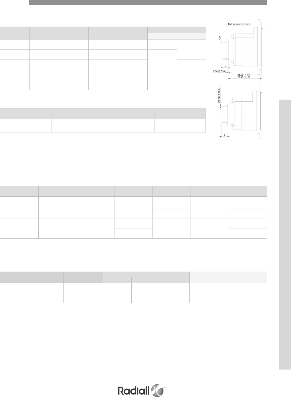
6-41
Our Most Important Connection is with You.™
Go online for data sheets & assembly instructions Visit www.radiall.com and enter the part number
CONTACTS WITH PC TAIL SIZES 22, 20HD & 16
Contact size Contact
arrangement Pin Socket Ins / Ext
tool
Dimensions mm (inch)
A B
22 81C3 -106 /620361 282500 5.95/6.75
(0.234/0.265) 0.6 +/-0,03
(0.023)
20HD 40-45-67-
33C4-57 616220 /282503 4.3/5.1
(0.169/0.200)
16 (1) 26-67-33C4
616235 /
282504 Max. 1
(0.039)
616235010 /3.55/4.32
(0.140/0.170)
616234 /10.20/11
(0.400/0.433)
NOTE:
(1) Front release front removable size 16 contacts PC tail termination are installed only for 26 contact arrangement (which is fitted with
616235 contacts). For 67 and 33C4, contact arrangements front release front removable size 16 contacts must be ordered separately
Contacts
Contact size AWG Contact
arrangement Pin Socket Ins / Ext
tool
Dimensions A mm
(inch)
22 26
28
30 106 /
620351
(2 wraps levels) 282500
9.45/10.45
(0.372/0.412)
620352
(3 wrap levels) 12.75/13.75
(0.502/0.541)
20HD 26
28
30 40-45-67-33C4-57
616222
(2 wraps levels) /282503
10/11
(0.394/0.433)
616224
(3 wrap levels) 13.3/14.3
(0.523/0.563
Contacts are delivered installed in the connector. For 67 and 33C4 contact
arrangements, front release front removable size 12 and 16 contacts are not
delivered with the connector. They must be ordered separately and chosen among
size 16 PC tail contacts and 616326 size 16 solder cup contact (rear extension from
insert: 4.4/5.2 (0.173/0.204).
CONTACTS WITH WIRE WRAP POST SIZES 22 & 20HD
Contact
size
Contact
arrangement Cable Pin Socket Center contact Outer body
Crimping tool Positioner SEL. Crimping tool Die Hex
533C4
81C3
Microdot
250.39.37 616126 /282281
(M22550/2-01) 282974 6282293
(M22520/5-01)
282246
(M22520/5-05) B
RG 178
KX 21 616127 /
These coaxial contacts are rear release rear removable and designed to be installed in 33C4 and 81C3
contact arrangement class F or K. They must be ordered separately.
COAXIAL CRIMP CONTACTS FOR 33C4 CONTACT ARRANGEMENTS SIZE 5
Radiall offers a unique solution to equip your DSX connectors with EN4531 fiber optic contacts. The
adapter will turn a ARINC 404 size 5 cavity into a fiber optic link, using EN4531-101 fiber optic contacts.
EN4531-101 adapter for size 5 cavity is available for DSX F connectors
with inserts 33C4 and 81C3 only, see page 6-28
EN4531-101 (ABS 1379) ADAPTER FOR SIZE 5 CAVITY
Contacts are delivered installed in the connector
Part number contact termination Dimension X
(mm inch) Ins/Ext tool
620176008 Y
7.20/6.40
[.283/.252] 282549009
SIZE 8 PIN QUADRAX CONTACTS
DSX SERIES
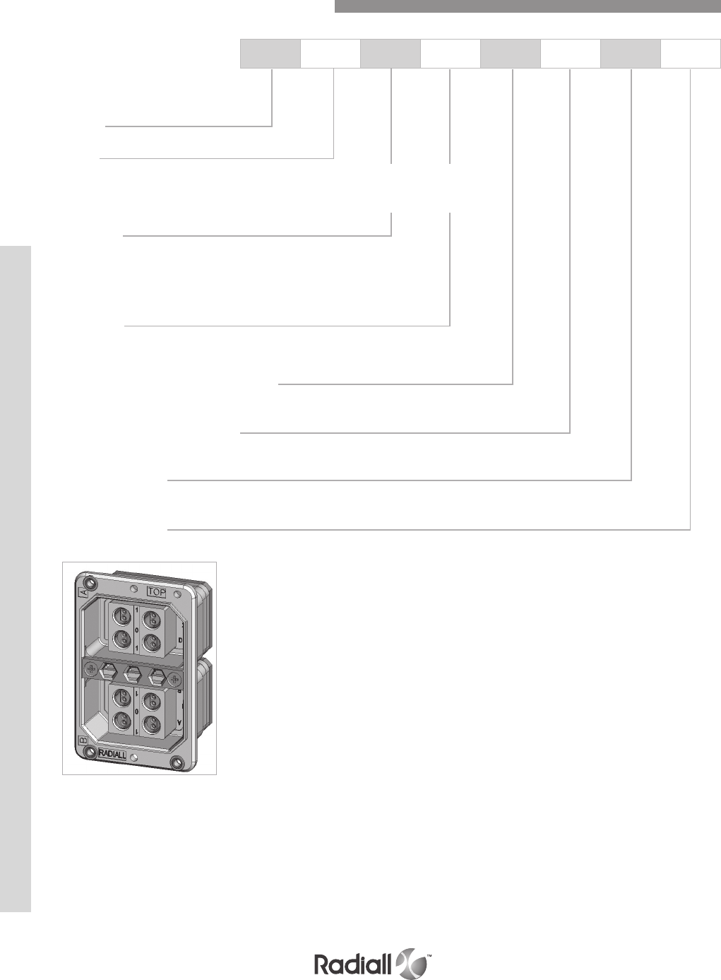
DSX SERIES
6-42
Our Most Important Connection is with You.™
Go online for data sheets & assembly instructions Visit www.radiall.com and enter the part number
DSX E 2 P B4TP S67S 00 01
NOTES:
(1) Data bus contact arrangements have no interfacial seal and no rear grommet
Series
Class
N: Non environmental (without grommet and interfacial seal)
E: Environmental (with grommet and interfacial seal)
T: Connector with interfacial seal on insert with protruding contacts only
Shell size
1: One gang shell
2: Two gang shell
3: Three gang shell
4: Four gang shell
Shell type
R: Receptacle
P: Plug
Gang A BUS contact arrangement (1)
Refer to page 6-43
Gang B contact arrangement
Refer to page 6-43
Modification code
See from page 6-13 to 6-19
Polarization code
See page 6-20 for selection
For Technical Characteristics please see pages 6-7
For any additional information ask for the RP2667 DSX Data Bus from Radiall
How to Order DSX-Data Bus Connectors
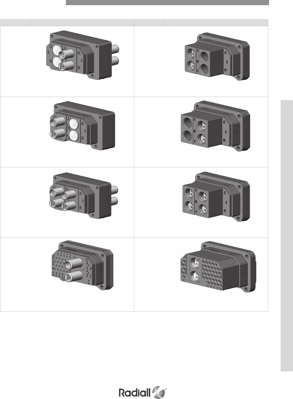
6-43
Our Most Important Connection is with You.™
Go online for data sheets & assembly instructions Visit www.radiall.com and enter the part number
Insert name Number of contacts Insert name Number of contacts
B2TP1 –
H2TP1
2 x Twinax
Location A, B
B2S1
2 x Twinax
Location A, B
B2TP2 –
H2TP2
2 x Twinax
Location C, D
B2S2
2 x Twinax
Location C, D
B4TP -
H4TP
4 x Twinax
Location A, B, C, D
B4S
4 x Twinax
Location A, B, C, D
S42B2P
2 x Twinax
42 x #20HD
Location A, B
S42B2S
2 x Twinax
42 x #20HD
Location A, B
PIN INSERT MATING SIDE SHOWN – ALL INSERTS DWV 1000 V AC
Contact Arrangements
DSX SERIES
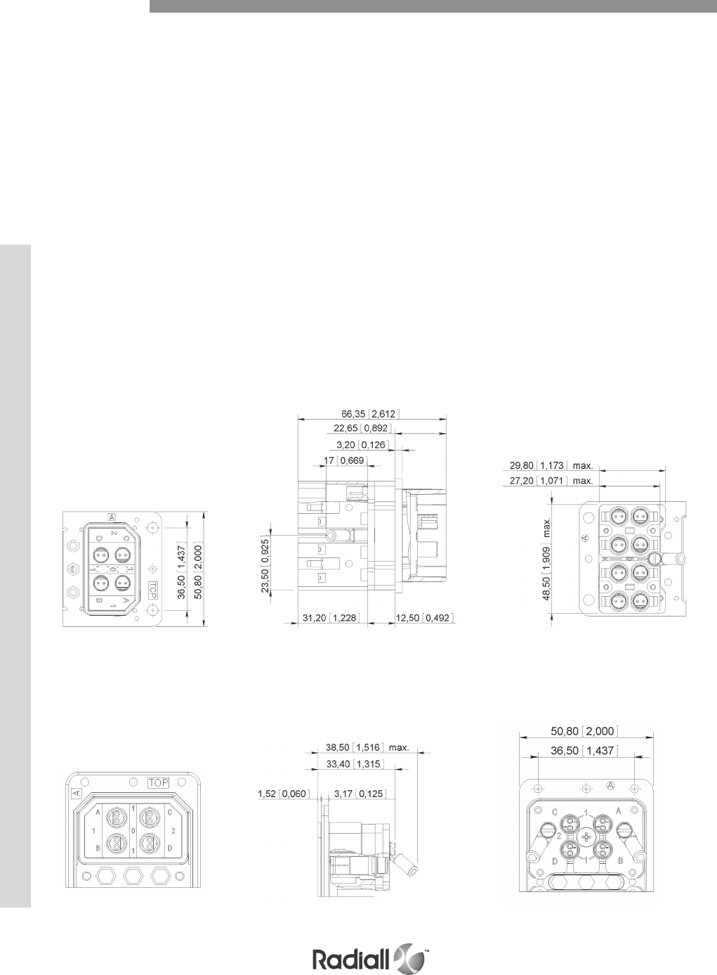
DSX SERIES
6-44
Our Most Important Connection is with You.™
Go online for data sheets & assembly instructions Visit www.radiall.com and enter the part number
B2TP, H2TP, B4TP & H4TP AIRCRAFT CONNECTOR
B2TP, H2TP, B4TP & H4TP EQUIPMENT CONNECTOR
MATING FACE WIRING REAR FACE
Dimensions
The aircraft connector is comprised of two sub assemblies
1- A plug shell fitted with an insert incorporating 2 (B2TP or
H2TP) or 4 (B4TP or H4TP) twinax pin contacts.
2- One or two connection plugs depending on the number of BUS lines (B2 or B4). If there
are two BUS lines (B2TP or H2TP) the two twinax contacts and the connection plug can
be installed either in position 1 (B2TP1 or H2TP1) or in position 2 (B2TP2 or H2TP2).
The difference between B2TP1 and H2TP1, B2TP2 and H2TP2, B4TP and
H4TP depends on the shielded twisted pairs cable that is used.
For Fileca F2709/12 cable the designation used are B2TP1, B2TP2, B4TP.
Description: differential impedance = 75 ± 5Ω
Shielded twisted pair (each conductor = AWG 20) Outer diameter = 5.35mm (0.206 inch max)
For Fileca F2709/9 cable the designation used are H2TP1, H2TP2, H4TP.
Description: differential impedance = 75 ± 5Ω
Shielded twisted pair (each conductor = AWG 22) Outer diameter = 4.80mm (0.189 inch max)
The equipment connector is comprised of one receptacle shell fitted
with an insert incorporating 2 (B2S) or 4 (B4S) twinax socket contacts.
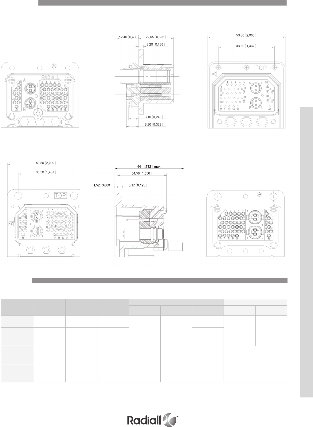
6-45
Our Most Important Connection is with You.™
Go online for data sheets & assembly instructions Visit www.radiall.com and enter the part number
S42B2P AIRCRAFT CONNECTOR
TWINAX
S42B2P EQUIPMENT CONNECTOR
Contact
size Cable Pin Socket
Center contact Outer body
Crimping tool Positioner SEL. Crimping tool Die
B2TP
B4TP F2709/12 /616090
282281
(M22520/2-01) 282959
7
282293
(M22520/5-01)
282248
OCETA
M1001
H4TP
H2TP
42B2S
F2709/9 /616091 8
B4S
B2S
AWG 20
AWG 22
AWG 24
/616092
7
6
5Not applicable
42B2P
AWG 20
AWG 22
AWG 24
616192 /
7
6
5
Dimensions
The aircraft connector is comprised of a plug shell fitted with a S42B2P insert
The equipment connector is comprised of a receptacle shell fitted with a S42B2P insert
Contacts
DSX SERIES
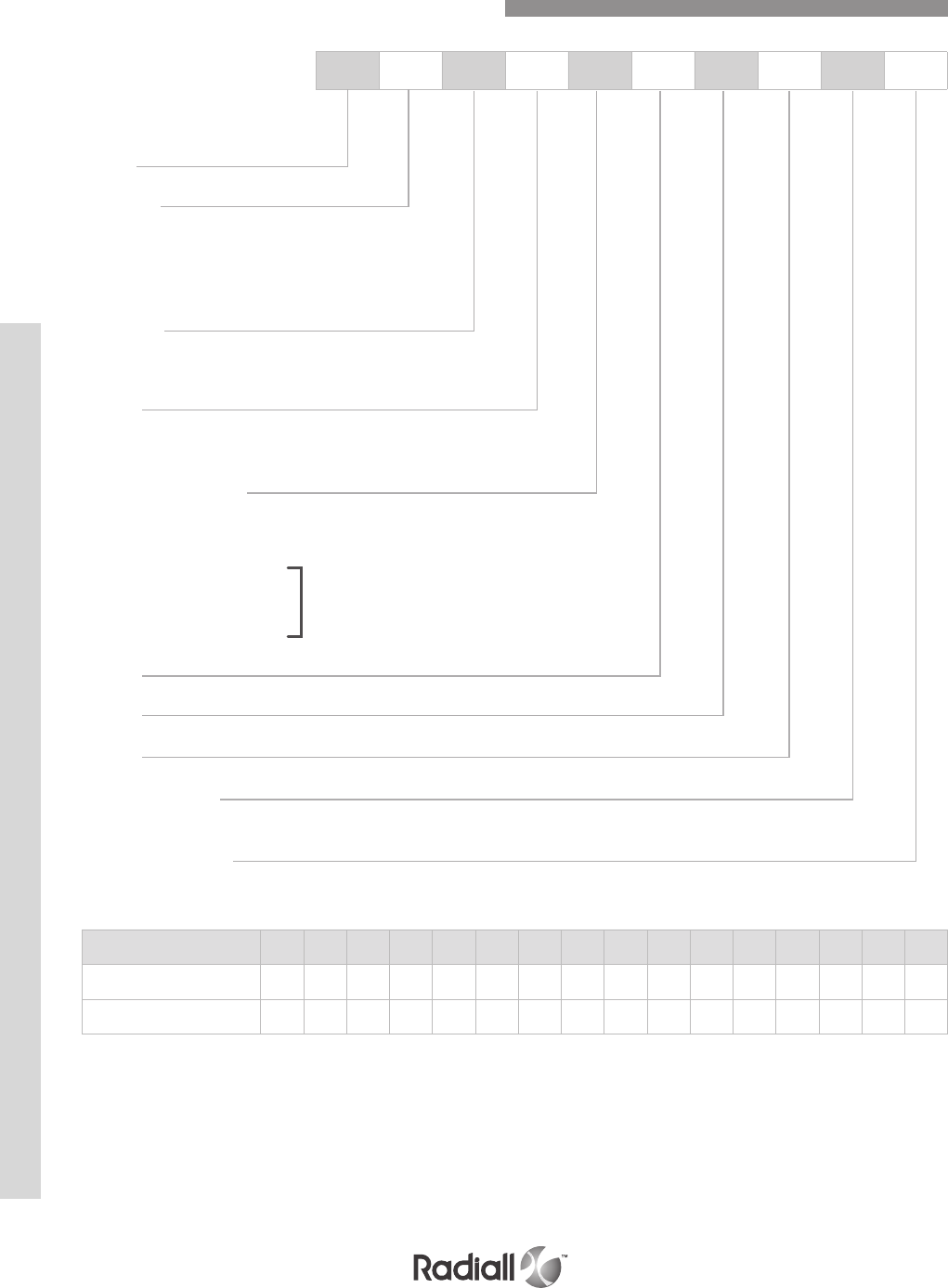
DSX SERIES
6-46
Our Most Important Connection is with You.™
Go online for data sheets & assembly instructions Visit www.radiall.com and enter the part number
DSX 4 G 13 S 14S 16S 25S 00 01
NOTES:
(1) If you need to use reduced crimp barrel contacts, use code X and order contacts separately
(2) For C2, C3 and C8 contact arrangements which include coax contacts, use termination code X and order coax contacts separately.
(3) For mixed layout 32C2, 32C4 and 40C1, the connector is delivered with signal and power
contacts but without coax contacts. Order coaxial contacts separately
(4) Without polarization code: the connector is delivered with polarizing system unassembled
Polarization code 00: the connector is delivered without polarizing system
Polarization code from 01 to 216: the connector is delivered with the polarization hardware assembled as defined by code
(5) For contact arrangement 67 and 32C4 with K, V, W or Y termination styles, size 16 contacts are crimp contacts shipped loose with the connector
00 813 26 40 45 57 67 106 32C2 32C4 40C1 C2 C3 C8 D8
Insert for pin contacts 10 12 44 14 16 18 20 22 24 26 40 28 34 36 30 38
Insert for socket contacts 11 13 45 15 17 19 21 23 25 27 41 29 35 37 31 39
CONTACT ARRANGEMENT CODE TABLE
How to OrderArinc 404 Shell type B Connectors
Note 5
Series
Shell size
1: One gang shell
2: Two gang shell
3: Three gang shell
4: Four gang shell
Shell type
G: Receptacle
H: Plug
Gang A
Contact arrangement
See available contact arrangements on pages 6-48 and 6-49
Termination style (2+3)
X: Without contacts
S: Crimp (1)
Z: Fixed solder cup
K: Wire wrap one levels
V: Wire wrap two levels
W: Wire wrap three levels
Y: PC tail contact
Gang B
Gang C
Gang D
Modification code
See from page 6-13 to 6-19 for selection
Polarization code (4)
See page 6-20 for selection

6-47
Our Most Important Connection is with You.™
Go online for data sheets & assembly instructions Visit www.radiall.com and enter the part number
MATERIALS
Description Material Plating
Shell Aluminium alloy Cadmium yellow chromate*
Insert Thermosetting resin /
Metallic insert Aluminium alloy Cadmium clear chromate
Rear spacer Silicone rubber /
Retention clip Copper alloy /
Contact Copper alloy Gold over nickel under plate
Insert retention plate AluminIum alloy Yellow anodized
Insert retention plate with attaching tabs AluminIum alloy Cadmium yellow chromate*
Polarizing posts Stainless steel /
Polarizing keys Zinc alloy Cadmium yellow chromate*
Polarizing keys retention plate Aluminium alloy Yellow anodised*
Screws, washers, clinch-nuts Corrosion resistant steel /
* More platings are available, see descriptions in modification codes
They are the same as those described for SAE AS81659 connectors on page 6-7.
These characteristics are the same as described in SAE AS81659, with the exception that the altitude
moisture test is not performed. This test is replaced by a moisture resistance test performed according
to method 1002.2 type II of MIL-STD-1344A.
Technical Characteristics
Electrical Characteristics
Mechanical and Environmental Characteristics
DSX SERIES
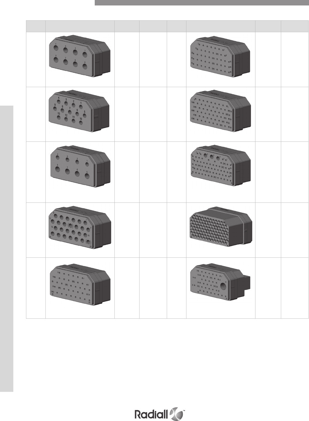
DSX SERIES
6-48
Our Most Important Connection is with You.™
Go online for data sheets & assembly instructions Visit www.radiall.com and enter the part number
Insert
name
Number of
contacts DWV Termination
availability
Insert
name
Number of
contacts
DWV
(1)
Termination
availability
8
8 x #12
1500V –
60Hz S- Z 45
45 x #20
1500V –
60Hz
For pin
S-Z-Y-K-V-W
For socket
S-Z-W
13
13 x #16
1800V –
60Hz
S - Z
For pin 57
57 x #20
1500V –
60Hz
For pin
S-Z-Y-K-V-W
For socket
S-Z-W
D8
4 x #16
4 x #12
1500V –
60Hz S – Z 67
64 x #20HD
3 x #16
1000V –
60Hz
For pin
S-Z-Y-K-V-W
For socket
S-Z-W
26
26 x #16
1500V –
60Hz
For pin
S-Z-K
For Socket
S-Z
106
106 x #22
1000V –
60Hz S-Y-V-W
40
40 x #20
1500V –
60Hz
For pin
S-Z-Y-K-V-W
For socket
S-Z-W
40C1
1 x #5 (coax)
39 x #20
1500V –
60Hz
For pin
S-Z-Y-K-V-W
For socket
S-Z-W
Pin insert mating side is shown below in the table
NOTE:
(1) Dieletric withstanding voltage
Contact Arrangements
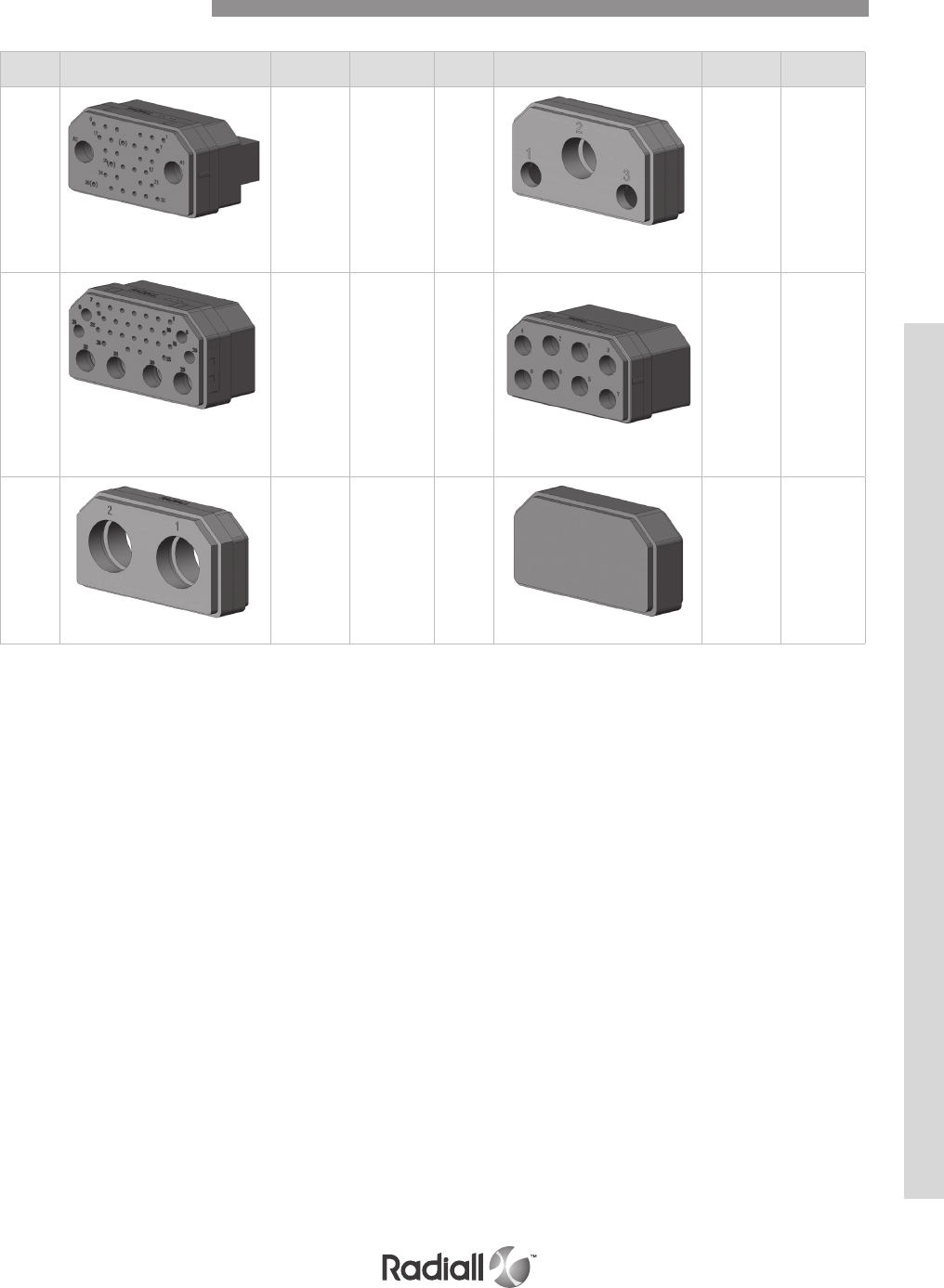
6-49
Our Most Important Connection is with You.™
Go online for data sheets & assembly instructions Visit www.radiall.com and enter the part number
Insert
name
Number of
contacts DWV Termination
availability
Insert
name
Number of
contacts DWV Termination
availability
32C2
2 x #5 (coax)
30 x #20
1500V –
60Hz
1000V for
coax cavity
For pin
S-Z-Y-K-V-W
For socket
S-Z-W
C3
2 x #7 (coax)
1 x #3
Metallic S
32C4
4 x #9 (coax)
4 x #16
24 x #20
1500V –
60Hz
1000V for
coax cavity
For pin
S-Z-Y-K-V-W
For socket
S-Z-W
C8
8 x #9 (coax)
1000V –
60Hz S
C2
2 x #1 (coax)
Metallic S 00 Dummy
insert
Contact Arrangements
DSX SERIES

DSX SERIES
6-50
Our Most Important Connection is with You.™
Go online for data sheets & assembly instructions Visit www.radiall.com and enter the part number
SIGNAL AND POWER CRIMP CONTACTS SIZES 22, 20HD,16 & 12
Contact
size
Wire
Pin
Radiall P/N
MIL P/N
Socket
Radiall P/N
MIL P/N
Crimping tool Positioner SEL. Ins/Ext Tool
AWG
Cross
section
(mm)
Wire
outside
dia.
(inch)
Striping
length
mm
(inch)
22 22
24
26
0.38
0.21
0.14
1.4
(0.055) 3.05
(0.138) 616200
(MIL 39029/11-144) 616300
(MIL 39029/12-148)
282281
(M22520/2-23)
282970
(M22520/2-23)
4
3
3282885
(M81969/1-01)
22
reduced
crimp
barrel
28
30 0.093
0.055 1.4
(0.055) 3.05
(0.138) 616201 616301 5
4
20HD 20
22
24
0.60
0.38
0.21
1.8
(0.071) 4.0
(0.157) 616210
(MIL 39029/11-145) 616310
(MIL 39029/12-149) 282971
(M22520/2-08)
7
6
5282886
(M81969/1-02)
20HD
reduced
crimp
barrel
26
28
30
0.14
0.093
0.055
1.8
(0.071) 4.0
(0.157) 616211 616311 6
5
4
20 20
22
24
0.60
0.38
0.21
1.8
(0.071) 4.0
(0.157) 610220 610325
282971
(M22520/1-01)
282972
(M22520/1-02)
4
3
3282943
20
reduced
crimp
barrel
26
28
30
0.14
0.093
0.055
1.8
(0.071) 4.0
(0.157) 610221 610321 3
3
2
16 16
18
20
1.34
0.93
0.60
2.6
(0.102) 6.0
(0.236) 616230
(MIL 39029/11-146) 616330
(MIL 39029/12-150)
6
5
4282546
(M81969/1-03)
16
reduced
crimp
barrel
20
22
24
0.60
0.38
0.21
2.6
(0.102) 6.0
(0.236) 616231 616331 5
5
4
12 12
14
16
3.18
1.91
1.34
3.4
(0.134) 6.0
(0.236) 616240
(MIL 39029/11-174) 616340
(MIL 39029/12-151) 282579
(M22520/1-11)
8
7
6
282547
(M81969/28-02)
Contact size Contact
arrangement Pin Socket Extraction
tool
Dimensions mm (inch)
Y B Dia D E
22 106
616206* 616379
282890
6.1/5.3
(0.240/0.209) 6.5 (0.256)
0.6
(0.023)
25.25/25.75
(0.0994/1.013)
1.55/1.75
(0.061/0.069)
616303 14.4/13.6
(0.567/0.535) 9.4 (0.370)
616306* 5.9/6.7
(0.232/0.263) 3.8 (0.149)
20HD
67 610216* /
282891
5.75/6.65
(0.226/0.262)
/
0.8
(0.031)
29.20/29.80
(1.149/1.173)
5.40/5.80
(0.212/0.228)
32C4 6.35/7.55
(0.250/0.297)
29.70/30.30
(1.169/1.192)
67 610219 3.35/4.25
(0.131/0.168) 0.75
(0.029)
29.20/29.80
(1.149/1.173)
32C4 3.95/5.15
(0.155/0.203)
29.70/30.30
(1.169/1.192)
20 40-45-57
32C2-40C1 610226* /282943 6.10/7.40
(0.240/0.291) /0.8
(0.031)
28.55/29.15
(1.124/1.147)
5.40/5.80
(0.212/0.228)
PC TAIL CONTACTS SIZES 22, 20HD & 20 PC TAIL CONTACTS
Connectors delivered in the “Y” termination style will be fitted with contacts
marked by “*”. If you want to use another kind of PC tail contact use
termination “x” when ordering the connector and order contacts separately
Contacts
PC tail contacts are delivered installed in the connector. Connectors with PC tail
contacts have no wire separator. For 32C4 and 67 contact arrangements, size 16 contacts
are delivered in crimp termination and are shipped loose with the connector.
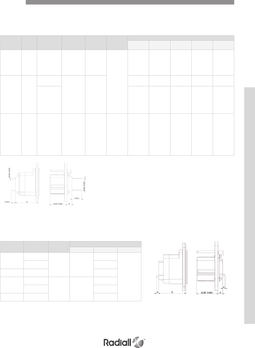
6-51
Our Most Important Connection is with You.™
Go online for data sheets & assembly instructions Visit www.radiall.com and enter the part number
Contact size AWG Contact
arrangement Pin Socket Extraction
tool
Dimensions mm (inch)
D E K (1 wrap) V (2 wrap) W (3 wrap)
22
26
28
30
106
610203
(2 wrap levels)
610204
(3 wrap levels)
610303
(2 wrap
levels)
610304
(3 wrap
levels)
282948
25.25/25.75
(0.0994/1.013)
1.55/1.75
(0.061/0.069)
10/11
(0.394/0.433)
12.50/13.50
(0.492/0.531)
20HD
26
28
30
67 610217
(1 wrap level)
610215
(2 wrap levels)
610214
(3 wrap levels)
/
28.8/29.2
(1.133/1.150)
5.40/5.80
(0.212/0.228)
6.35/7.35
(0.250/0.289)
9.35/10.35
(0.368/0.407)
11.85/12.85
(0.466/0.506)
32C4 29.70/30.30
(1.169/1.192)
5.40/5.80
(0.212/0.228)
6.95/8.25
(0.273/0.325)
9.95/11.25
(0.391/0.443)
12.45/13.75
(0.490/0.541)
20
26
28
30
40-45-57
32C2-40C1
610228
(1 wrap level)
610225
(2 wrap levels)
610224
(3 wrap levels)
/282949 28.55/29.15
(1.147/1.124)
5.40/5.80
(0.212/0.228)
6.95/8.25
(0.273/0.325)
9.95/11.25
(0.391/0.443)
12.60/13.8
(0.496/0.543)
CONTACTS WITH WIRE WRAP POST SIZES 22, 20HD & 20
THERMOCOUPLE CONTACT SIZES 22 & 20HD refer to page 6-22
FIBER OPTIC TERMINI SIZES 16 & 12 refer to page 6-23
Contact size Contact
arrangement
Stripping
length
Dimensions mm (inch)
A D E
20HD
67
2.5
(0.098)
3
(0.118)
29.20/29.80
(1.149/1.173)
5.40/5.80
(0.212/0.228)
32C4 29.70/30.30
(1.169/1.192)
20 40-45-57-
32C2-40C1
28.55/29.15
(1.124/1.147)
16
26-67
5
(0.197)
4.5
(0.177)
29.20/29.80
(1.149/1.173)
32C4 29.70/30.30
(1.169/1.192)
12 8-D8 28.55/29.15
(1.124/1.147)
SOLDER CUP CONTACT SIZES 20HD, 20, 16 & 12
Contacts
Wire wrap contacts are delivered installed in the connector. Connectors with wire wrap
contacts have no wire separator. For 32C4 and 67 contact arrangements, size 16 contacts
are delivered in crimp termination and are shipped loose with the connector.
Solder cup contacts are fixed contacts delivered
installed in the connector. Connectors with solder cup
contacts have no wire separator.
DSX SERIES

DSX SERIES
6-52
Our Most Important Connection is with You.™
Go online for data sheets & assembly instructions Visit www.radiall.com and enter the part number
Contact
size
Contact
Arrangement Cable Pin Socket
Center contact Outer body
Crimping tool Positioner SEL. Crimping tool Die Hex
1C2
UT 141 RG
402 616005 /Solder contact
RG 58
RG 141
KX 15
616005
Right
angle
/
Solder contact
282293
(M22520/5-01)
282246
(M22520/5-05) A
RG 214 RG
225 /610108 282247
(M22520/5-61) A
SMA 616009 /SMA termination
COAXIAL CRIMP CONTACT SIZE 1
For other cables, please consult Radiall.
Contact
size
Contact
Arrangement Cable Pin Socket
Center contact Outer body
Crimping tool Positioner SEL. Crimping tool Die Hex
532C2
40C1
RG 58
RG 141
KX 15
610120 610020001
Solder 282293
(M22520/5-01)
282246
(M22520/5-05)
A
RG 142
RG 223
KX 23
610122 610022001
RG 316
KX 22 610126 610026
B
KX 21
DT 610127 /
RG 178 610119 /
UT 085 610123 /
UT 141 616009 /Solder
COAXIAL CRIMP CONTACT SIZE 5
For other cables, please consult Radiall.
Extraction tool: 282946 (M81969/28-01)
Contact size Contact
Arrangement Cable Pin Socket
Center contact Outer body
Crimping tool Positioner SEL. Crimping tool Die Hex
3C3
RG 214
RG 225 /610118 Solder 282293
(M22520/5-01)
282247
(M22520/5-61) A
UT 141
RG 402 616014 /Solder contact
COAXIAL CRIMP CONTACT SIZE 3
For other cables, please consult Radiall.
Dielectric withstanding voltage at sea level: 1500 V rms
Contacts
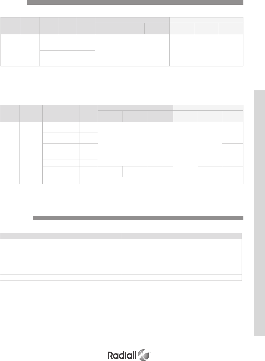
6-53
Our Most Important Connection is with You.™
Go online for data sheets & assembly instructions Visit www.radiall.com and enter the part number
Contact
size
Contact
Arrange-ment Cable Pin Socket
Center contact Outer body
Crimping tool Positioner SEL. Crimping tool Die Hex
9C8
32C4
RG 316
KX 22 610146 610046
Solder 282293
(M22520/5-01)
282246
(M22520/5-05)
B
RG 178
KX 21 610147 610047
RG 58
RG 141
KX 15
610140 610040 A
RG 142 610149 610049
S280W
503-2 /610044 282281
(M22520/2-01)
DANIELS
K345 6282236
(M22520/5-45) B
UT 085 610148 /Solder
COAXIAL CRIMP CONTACT SIZE 7
COAXIAL CRIMP CONTACT SIZE 9
For other cables, please consult Radiall.
Extraction tool: 282946 (M81969/28-01)
Dielectric withstanding voltage at sea level: 750 V rms
For other cables, please consult Radiall.
Extraction tool: 282946 (M81969/28-01)
For Dust caps & backshells please refer to page 6-29 and 6-30
Contact
size
Contact
Arrange-
ment
Cable Pin Socket
Center contact Outer body
Crimping tool Positioner SEL. Crimping tool Die Hex
7C3
RG 58
RG 141
KX 15
610120 610020001
Solder 282293
(M22520/5-01)
282246
(M22520/5-05) A
RG 174
RG 316
RG 188
610126 610026
FILLER PLUGS
Designation Filler Plugs Part Number
Size 22 (black) 620920
Size 20 (white) 610940
Size 20HD (red) 610941
Size 16 (blue) 620922
Size 12 (yellow) 616923
Size 5 (white) 616802
Size 9 (white) 616802
Contacts
Accessories
DSX SERIES
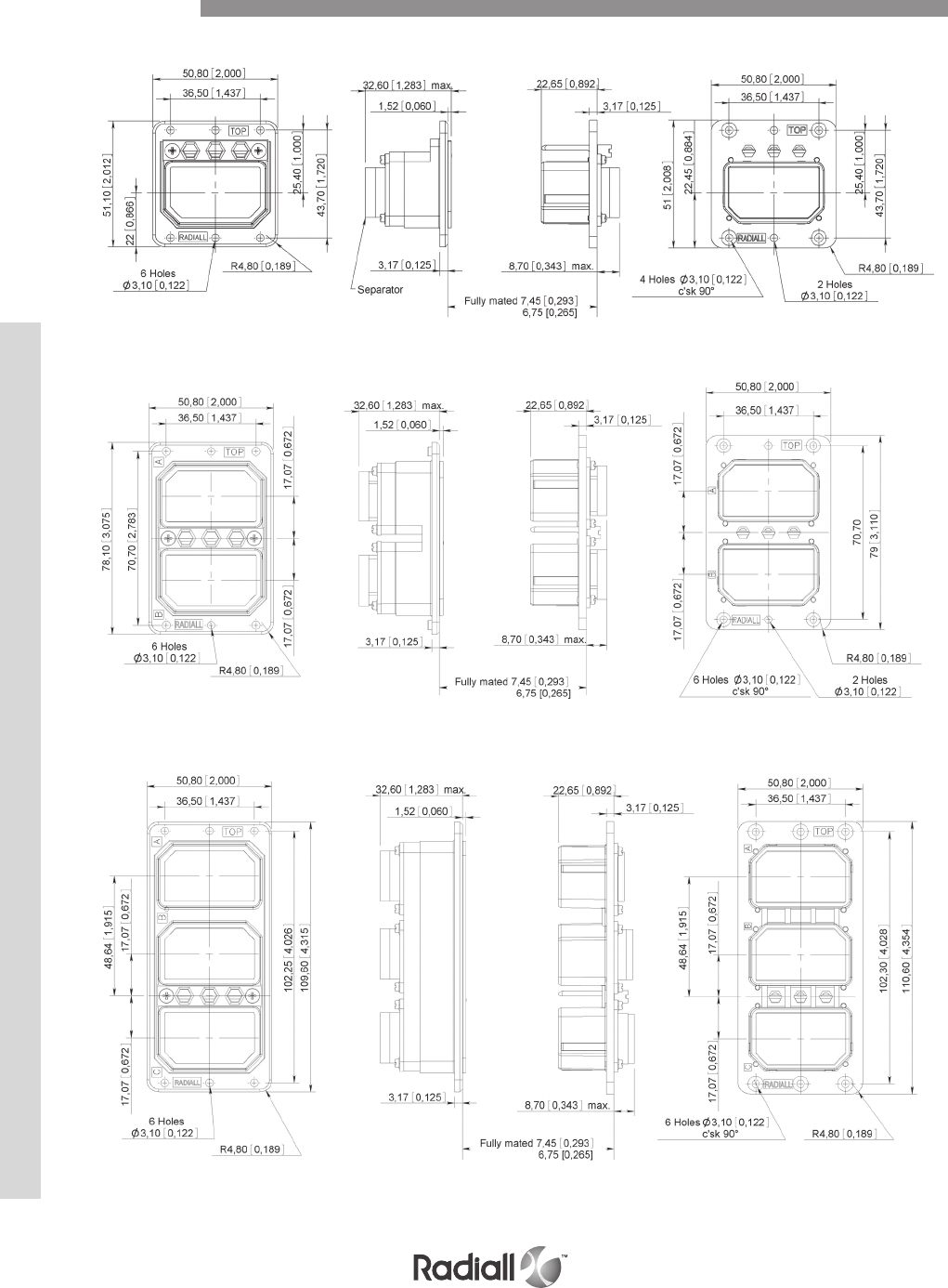
DSX SERIES
6-54
Our Most Important Connection is with You.™
Go online for data sheets & assembly instructions Visit www.radiall.com and enter the part number
SHELL SIZE 1 PLUGRECEPTACLE
SHELL SIZE 2 PLUGRECEPTACLE
SHELL SIZE 3 PLUGRECEPTACLE
Dimensions
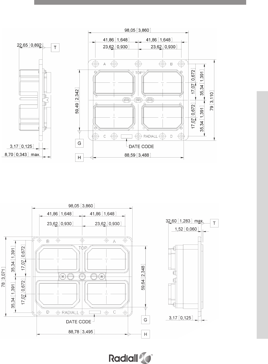
6-55
Our Most Important Connection is with You.™
Go online for data sheets & assembly instructions Visit www.radiall.com and enter the part number
SHELL SIZE 4
PLUG
RECEPTACLE
Dimensions
DSX SERIES
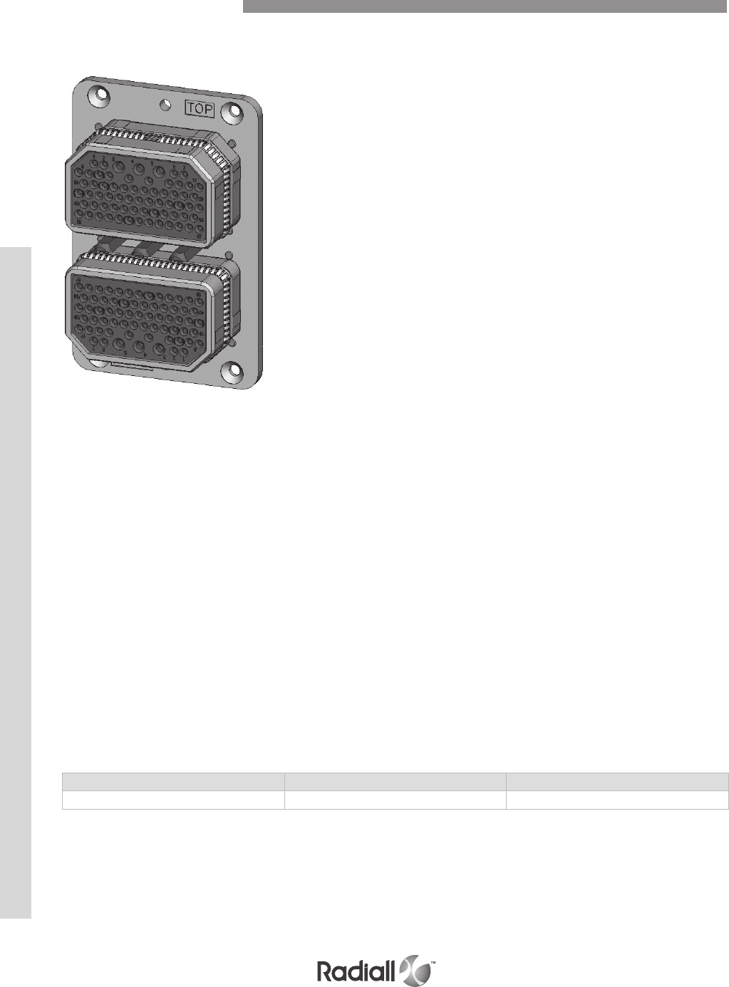
DSX SERIES
6-56
Our Most Important Connection is with You.™
Go online for data sheets & assembly instructions Visit www.radiall.com and enter the part number
EMI/RFI acts directly on electronics systems
whether by conduction mode through the input or
output cables or by radiation (coupling).
Electronics equipment is particularly vulnerable to interference
and can be disturbed or damaged by it. The serious consequences
which may result, make it essential to protect such installations.
The first stage in protection is to install the equipment in a
shielded cabinet which protects it from some interference;
particularly those occurring by radiation. At the connector
level that means to use metallic shells to have a good mass
conduction between the equipment box and the rack.
To meet these requirements RADIALL offers plug connectors
for rack which are fitted with grounding spring fingers.
DSX SAE AS81659 and DSX Arinc 404
shell type B in sizes 1,2,3, and 4
fitted with grounding fingers are available.
These connectors are interchangeable and
intermatable with the standard ones.
TECHNICAL CHARACTERISTICS
The technical characteristics are the same as those of SAE AS81659 and
Arinc 404 shell type B connectors except for the following.
Shell to shell conductivity: 2.5mΩ max. Measured according to method 3007 of MIL-STD-1344A.
Shielding effectiveness: >70 dB @ 4GHz. Measured according to method 3008 of MIL-STD-1344A.
PART NUMBERING
The part numbering system applies to plug shells only.
To establish the part number of a DSX EMI/RFI connector, simply add the letter “G” after the letter
which defines the shell type in the DSX SAE AS81659 or Arinc 404 shell type B standard part number.
Examples of part numbers:
DSXN2PGS404SS45S0001
DSX2HG41S19S0001
MATERIALS
Description Material Plating
Grounding spring fingers Copper alloy Nickel
DSX EMI/RFI Introduction

6-57
Our Most Important Connection is with You.™
Go online for data sheets & assembly instructions Visit www.radiall.com and enter the part number
MATERIALS
ELECTRICAL, MECHANICAL & ENVIRONMENTAL CHARACTERISITCS
Description Material Plating
Shell Aluminium alloy Cadmium yellow chromate
Insert Thermosetting resin /
Metallic insert Aluminium alloy Cadmium clear chromate
Rear spacer Silicone rubber /
Retention clip Copper alloy /
Contact Copper alloy Gold over nickel underplate
Insert retention plate Aluminium alloy Gold anodized
Screws, washers, clinch-nuts Corrosion resistant steel /
ARINC 404 Shell Type A Technical Characteristics
Refer to SAE AS81659 standards page 6-7
DSX SERIES
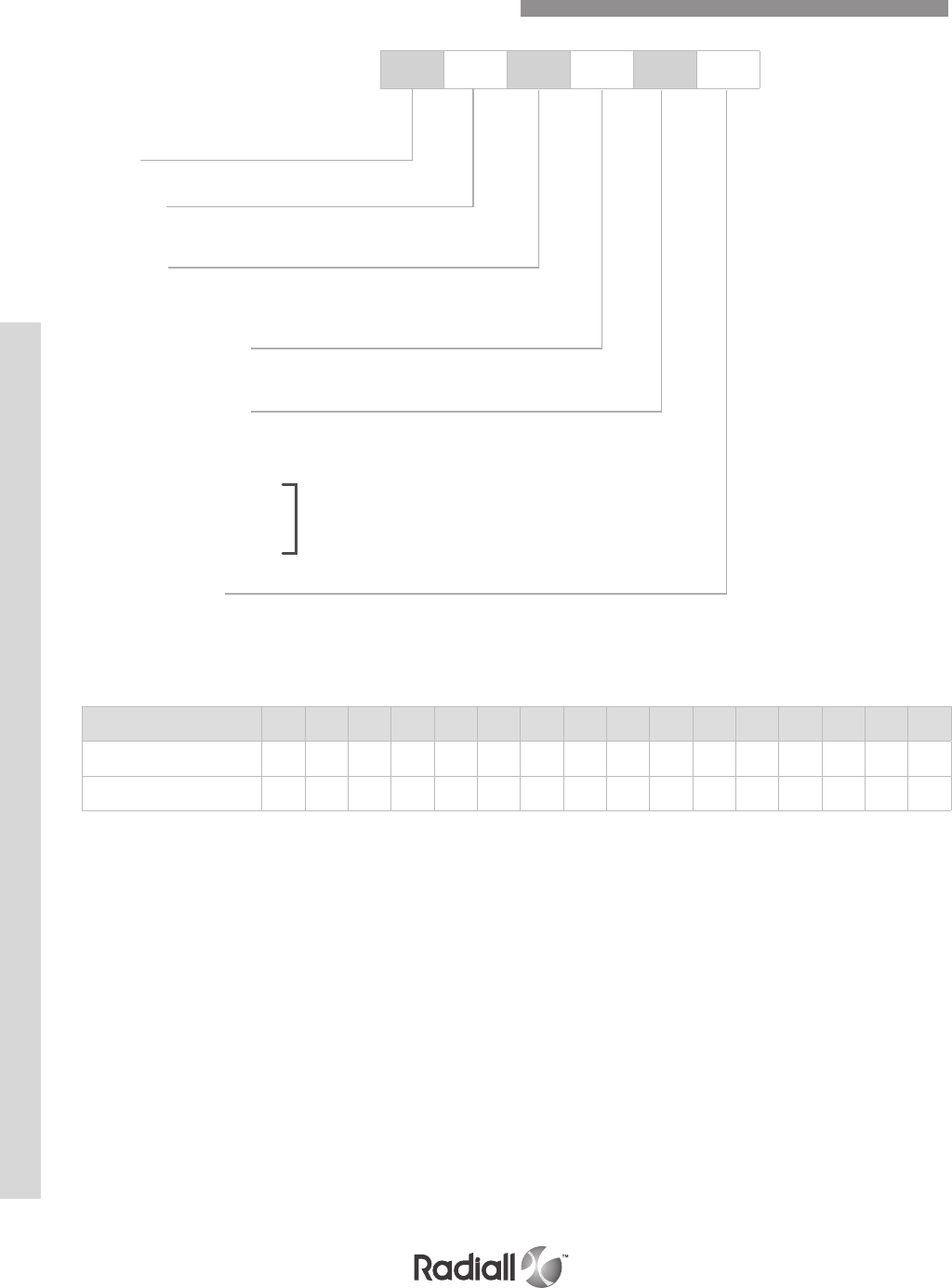
DSX SERIES
6-58
Our Most Important Connection is with You.™
Go online for data sheets & assembly instructions Visit www.radiall.com and enter the part number
DSX 1 F 18 S 00
Series
Shell size
1: One gang shell
Shell type
E : Receptacle
F: Plug
Contact arrangement
See table below and page 6-48
Termination style (2+3)
X: Without contacts
S: Crimp (1)
Z: Fixed solder cup
K: Wire wrap one levels
V: Wire wrap two levels
W: Wire wrap three levels
Y: PC tail contact
Modification code
See page 6-59
NOTES:
(1) If you need to use reduced crimp barrel contacts, use code X and order contacts separately
(2) For C2, C3 and C8 contact arrangements which include coax contacts, use termination code X and order coax contacts separately
(3) For mixed layout 32C2, 32C4 and 40C1, the connector is delivered with signal and power
contacts but without coax contacts. Order coaxial contacts separately
(4) For contact arrangement 67 and 32C4 with K, V, W or Y termination styles, size 16 contacts are crimp contacts shipped loose with the connector
How to Order ARINC 404 Shell Type A Connectors
Note 4
00 813 26 40 45 57 67 106 32C2 32C4 40C1 C2 C3 C8 D8
Insert for pin contacts 10 12 44 14 16 18 20 22 24 26 40 28 34 36 30 38
Insert for socket contacts 11 13 45 15 17 19 21 23 25 27 41 29 35 37 31 39
CONTACT ARRANGEMENT CODE TABLE
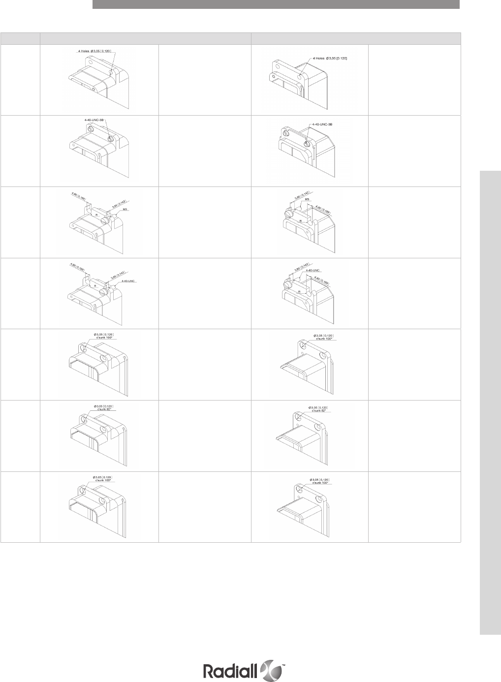
6-59
Our Most Important Connection is with You.™
Go online for data sheets & assembly instructions Visit www.radiall.com and enter the part number
CODE Receptacle shell Plug shell
00 4 holes Ø3.05 (0.120) 4 holes Ø3.05 (0.120)
01 Four 4.40 UNC 3B clinch nuts Four 4.40 UNC 3B clinch nuts
03
4 mounting slots
4.80 (0.189) wide
+ four M3 shouldered screws
+ 4 washers
4 mounting slots
4.80 (0.189) wide
+ four M3 shouldered screws
+ 4 washers
04
4 mounting slots
4.80 (0.189) wide
+ four 4.40 UNC
shouldered screws
+ 4 washers
4 mounting slots
4.80 (0.189) wide
+ four .40 UNC
shouldered screws
+ 4 washers
05 4 holes 3.05 (0.120)
dia c’sunk 100°
4 holes 3.05 (0.120)
dia c’sunk 100°
06 4 holes 3.05 (0.120)
dia c’sunk 82°
4 holes 3.05 (0.120)
dia c’sunk 82°
07
4 holes 3.05 (0.120)
dia c’sunk 100°
+ a dust cap
4 holes 3.05 (0.120)
dia c’sunk 100°
+ a dust cap
Dimensions mm (inch)
Modification Code
DSX SERIES
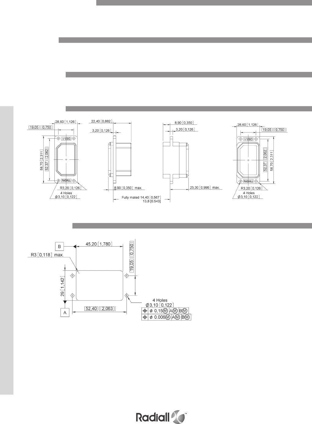
DSX SERIES
6-60
Our Most Important Connection is with You.™
Go online for data sheets & assembly instructions Visit www.radiall.com and enter the part number
They are the same inserts as those used in Arinc 404 shell type B connectors (see page 6-48)
The contacts used are those shown on page 6-50 to 6-53
Refer to page 6-53
Panel Cut-out
Accessories
Dimensions
Contacts
Contact Arrangements
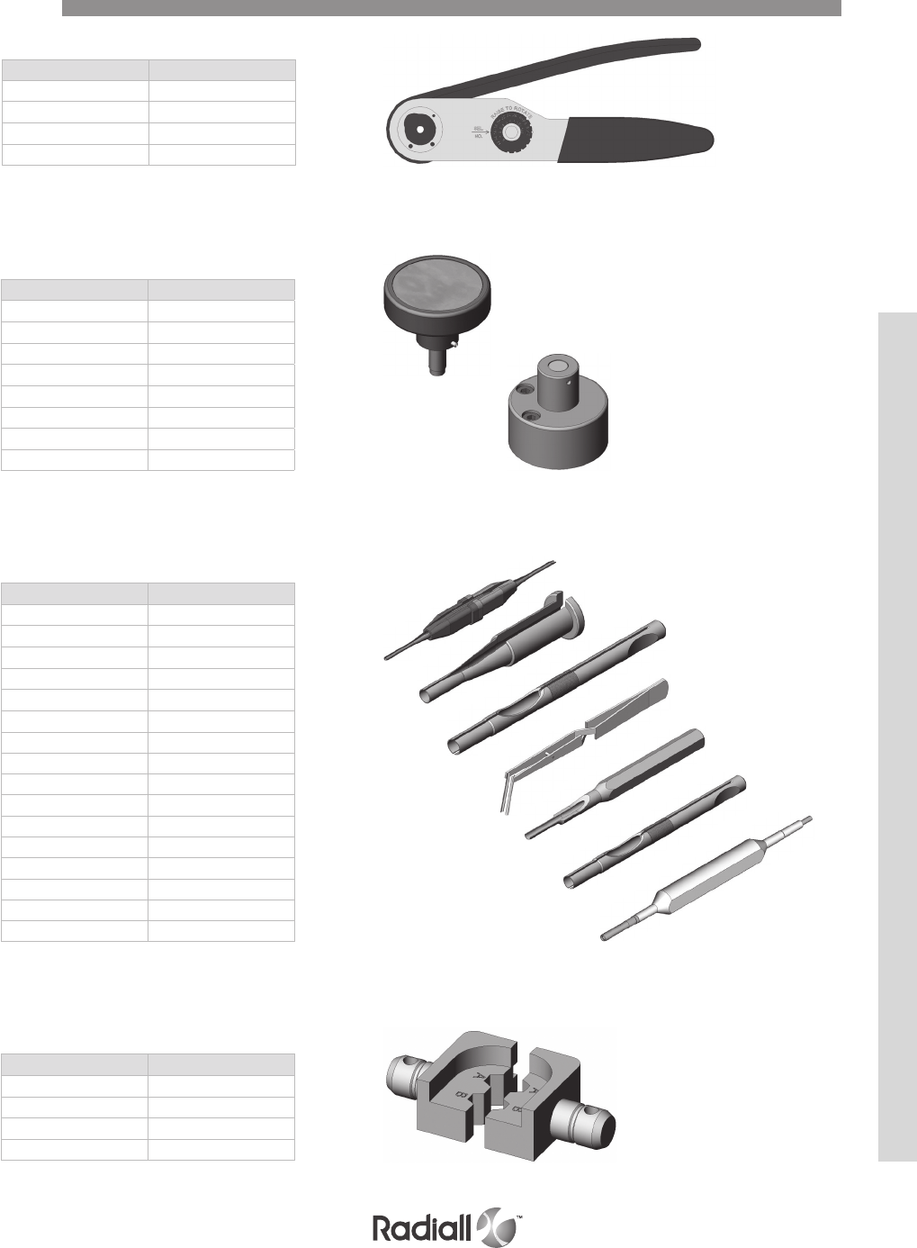
6-61
Our Most Important Connection is with You.™
Go online for data sheets & assembly instructions Visit www.radiall.com and enter the part number
Part number Mil spec P/N
282246 M22520/5-05
282247 M22520/5-61
282248 OCETA M1001
282236 M22520/5-45
DIE
Part number Mil spec P/N
282885 M81969/1-01
282886 M81969/1-02
282546 M81969/1-03
282547 M81969/28-02
282943 /
282946 M81969/28-01
282890 /
282892 /
282891 /
282929 /
282945 /
282500 /
282503 /
282504 /
282948 /
282949 /
INSERTION / EXTRACTION TOOLS
Part number Mil spec P/N
282970 M22520/2-23
282971 M22520/2-08
282974 /
282550 Daniels K345
282972 M22520/1-02
282579 M22520/1-11
282557 /
POSITIONERS
Part number Mil spec P/N
282281 M22520/2-01
282291 M22520/1-01
282296 DANIELS M300BT
282293 M22520/5-01
CRIMPING TOOLS
Tools
DSX SERIES

DSX SERIES
6-62
Our Most Important Connection is with You.™
Go online for data sheets & assembly instructions Visit www.radiall.com and enter the part number
Notes

SECTION 7
MMC Series

Our Most Important Connection is with You.™

SECTION 7 TABLE OF CONTENTS
Introduction .................................................................................................................. 7-4
Application ................................................................................................................... 7-4
Features ...................................................................................................................... 7-4
Product overview ............................................................................................................ 7-5
Electrical characteristics ................................................................................................... 7-6
Mechanical & environmental characteristics ............................................................................ 7-6
Product materials and masses ............................................................................................ 7-7
How to order connectors ................................................................................................... 7-8
Contact arrangements .............................................................................................. 7-9 & 7-10
Rack guides dimensions ........................................................................................... 7-11 & 7-12
Fixed jackscrews dimensions .................................................................................... 7-13 & 7-14
Rotating jackscrews dimensions ................................................................................. 7-15 & 7-16
Block 104 contacts ................................................................................................ 7-17 to 7-19
Block 158 contacts ................................................................................................ 7-20 & 7-21
Block 208 contacts ................................................................................................ 7-22 & 7-23
Contacts .................................................................................................................... 7-24
Front release and front removable contacts ........................................................................... 7-24
Equipment wire contacts ................................................................................................. 7-25
Twisted pair contacts ...................................................................................................... 7-26
Micro-coaxial contacts .................................................................................................... 7-27
Panel cut out ............................................................................................................... 7-28
Spare parts for guides .................................................................................................... 7-29
Spare parts for insulators, backshells and shrouds .................................................................. 7-30
Wiring instructions ................................................................................................ 7-31 to 7-34
Tools
..............................................................................................................
7-35
Contents
7-3
Our Most Important Connection is with You.™
Go online for data sheets & assembly instructions Visit www.radiall.com and enter the part number

MMC SERIES
A simple, yet highly reliable construction makes the MMC offering enormously adaptable through use of
the broad range of accessories. This has allowed the Radiall MMC series to be widely approved for the
use in all civil and military fields such as computers, telecommunications, medical, aeronautical, naval
and nuclear.
The Radiall MMC series was designed in response to the majority of connection problems
of cabling installation, internal and external on electrical and electronic equipment.
The series conforms to the French specification NF-C-93 426 HE 621-622.
They are made up of a rectangular insulation block which accepts equally male or female contacts
fitted with different types of wires and coaxial cables. A large number of accessories are available for
the MMC series, including: backshell with cable clamp, contact protection shrouds, and locking. This
makes it possible for the connector to be manufactured exactly to the corresponding needs of the user.
All of the contacts are removable in order to facilitate replacement, repairs or modification to circuits.
A range of robust manual and automatic tooling with easy to follow instructions provides straight-
forward connector/cable assembly. Fully conforms to the French specification NF-C-93 426 HE 621-622.
© Eurocopter - Jérome DEULIN
© Courtesy of US Army
Introduction
Applications
Features
7-4
Our Most Important Connection is with You.™
Go online for data sheets & assembly instructions Visit www.radiall.com and enter the part number

MMC SERIES
Detailed view of the various parts of this series connector.
Rotating fixing rod
used with backshell
Rotating fixing rod
used with backshell
Washer & nut
used without backshell
Backshell
Plug connector
Male rack guides
Female rack guides
Shroud (optional)
Washer & nut
Rotating fixing rod
used without backshell
Shroud (optional)
Rotating female jackscrew
Fixing male jackscrew
Receptacle connector
JACKSCREWS RACK GUIDES
Product Overview
7-5
Our Most Important Connection is with You.™
Go online for data sheets & assembly instructions Visit www.radiall.com and enter the part number
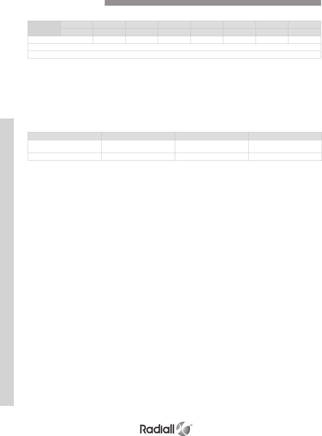
MMC SERIES
CONNECTORS
- Insulation resistance: > 5000 MΩ
- Dielectric withstanding voltage: 1500 V.r.m.s. @ 50Hz (at sea level)
MECHANICAL & ENVIRONMENTAL CHARACTERISTICS
- Retention of the contact in moulding: > 50 N (11.24 lbs)
- Mating force per contact pair: < 3.4 N (0.76 lbs)
- Durability: 500 matings
- Vibration: 20 g (0.71 oz) from 80 to 2000 Hz
- Shock: 50 g (1.76 oz)
- Temperature range: -55°C @ +125°C (-131°F to 257°F)
- Humidity: 21 days
- Salt spray: 48H
EQUIPMENT WIRE CONTACTS
Wire
section
AWG 16 18 20 22 24 26 28
mm21.34 0.93 0.60 0.38 0.22 0.14 0.093
Current rating (Amp.) 13 10 7.5 5 3 2 1
Maximum Ø on insulation 3.10
Contact resistance ≤ 5 m Ω
Frequency 0 – 200MHz 200 – 500 MHz 500 – 1000 MHz
Voltage standing wave
ratio (VSWR) 1.10 1.15 1.40
Insertion loss by pair (dB) < 0.015 < 0.025 < 0.025
COAXIAL CONTACTS
- Nominal impedance: 50Ω
- Operating frequency: 0 to 1000MHz
- Dielectric withstanding voltage: 600 V.r.m.s. @ 50Hz (at sea level)
- Insulation resistance: ≥ 5000 MΩ
- Contact resistance: ≤ 12 mΩ
Electrical Characteristics
7-6
Our Most Important Connection is with You.™
Go online for data sheets & assembly instructions Visit www.radiall.com and enter the part number
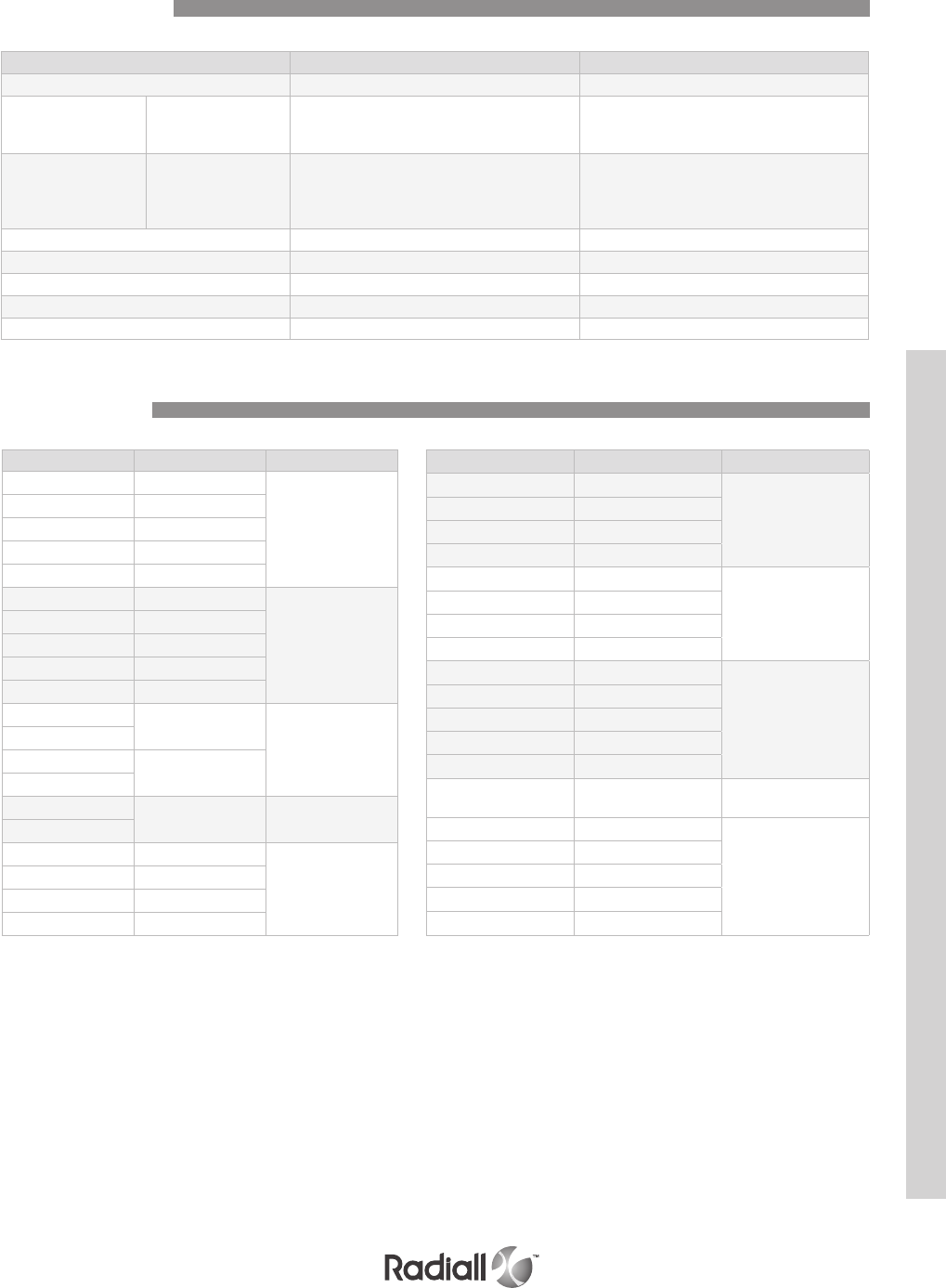
MMC SERIES
Description Material Plating
Connector Glass filled phenolic --
Equipment
Wire
Contacts
Body
Spring
Retention clip
Copper alloy
Gold over nickel
Gold over nickel
Nickel
Coaxial
Contacts
Body & center
Contacts
Ferrule
Insulator
Copper alloy
Copper alloy
PTFE
Gold over nickel
Nickel
Rack guide Brass Nickel plated
Jackscrews Stainless steel --
Shroud Steel Yellow chromate cadmium plated
Backshell Zinc or aluminium alloy Painted black
Strain relief cable clamp Stainless steel --
Size Masses g (oz) Type
14 7 (0.246)
Plug connector
20 8 (0.282)
26 11 (0.388)
34 19 (0.670)
42 22 (0.776)
690501 7 (0.246)
Receptacle
connector
690511 8 (0.282)
690521 11 (0.388)
690531 19 (0.670)
690541 22 (0.776)
690962 2 (0.070)
Rack guide
690952
690963 8 (0.282)
690953
690965 6 (0.211) Short jackscrew
690955
690966 15 (0.529)
Long jackscrew
690949 18 (0.634)
690956 16 (0.564)
690939 18 (0.634)
References Masses g (oz) Type
690940 15 (0.529)
Shroud male
690941 16 (0.564)
690942 18 (0.634)
690943 22 (0.776)
690930 14 (0.493)
Shroud female
690931 15 (0.529)
690932 17 (0.599)
690933 25 (0.881)
690905 57 (2.010)
Backshell top entry
690908 65 (2.292)
690911 77 (2.716)
690914 101 (3.562)
690917 125 (4.409)
20521500 39 (1.375) Backshell
side entry
(14) 690848001 14 (0.493)
Strain relief
top entry
(20) 690848002 16 (0.564)
(26) 690848003 18 (0.634)
(50) 690848006 28 (0.987)
(75) 690848007 40 (1.410)
Product Materials
Product Masses
7-7
Our Most Important Connection is with You.™
Go online for data sheets & assembly instructions Visit www.radiall.com and enter the part number
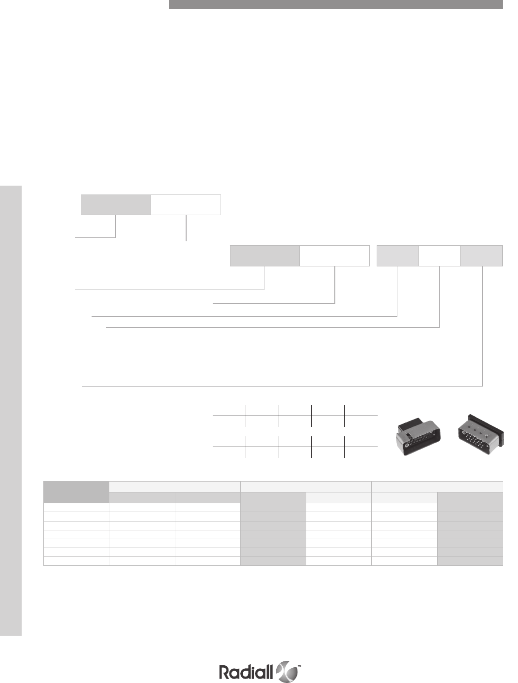
MMC SERIES
Series
Basic code (see table below for selection)
Connectors with accessories
Series
Basic code (see table below for selection)
Mandatory
Accessories (2)
O: no accessories
A: backshell top entry
B: backshell side entry (only 75 way)
C: top entry strain relief clamp (not available in 34 and 42 way)
Shrouds
0: no shroud
A: male shroud without polarizing (1)
male shroud with polarizing (2)
F: female shroud without polarizing (1)
female shroud with polarizing (2)
A pair of MMC connectors is made up of the following:
- A block “P” (plug)
- A block “R” (receptacle)
Of identical dimensions but distinguished by:
- The engraved letters “P” and “R” on the mating faces
- The contact identification and position of the cavities is a mirror image of the mating half.
Each block “P” and “R” must be fitted with male and female guides or jackscrews.
- On the block P female guide beside hole 1 or A
- On the block R male guide beside hole 1 or A (in order to prevent mismatching and misalignment).
Connectors with guides (without other accessories)
PART NUMBERING
690 600
690 600 OAO
In 1357
code B C D E
In 1357
code G H J K
Number of
contacts
Rack guides Fixed jackscrews Rotating jackscrews
Plug Receptacle Plug Receptacle Plug Receptacle
14 400 500 701 700 600 602
20 410 510 711 710 610 612
26 420 520 721 720 620 622
34 430 530 731 730 630 632
42 440 540 741 740 640 642
50 450 550 751 750 650 652
75 460 560 761 760 660 662
Example: 701 goes with 602
NOTES:
(1) Not available in 42 way
(2) Not available in 14 way
When connector has a shroud with polarizing, polarization starts from the cavity A or 1 side of the connector (refer to page 7-30)
How to Order Connectors
7-8
Our Most Important Connection is with You.™
Go online for data sheets & assembly instructions Visit www.radiall.com and enter the part number
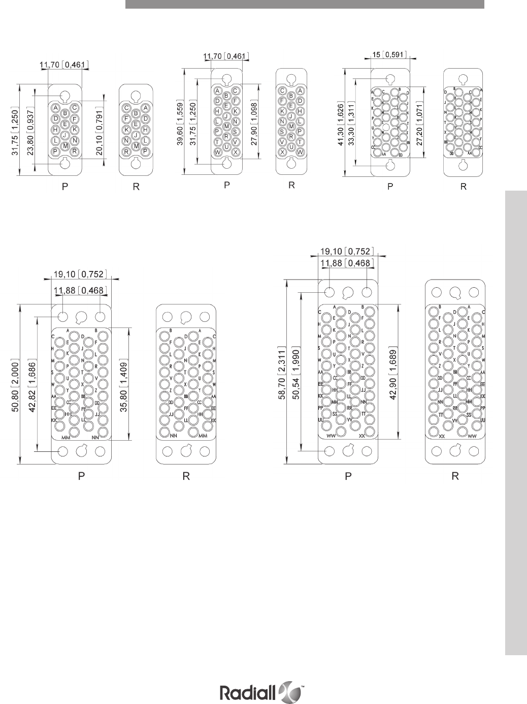
MMC SERIES
14 contacts
34 contacts
20 contacts
42 contacts
26 contacts
VIEW WIRING SIDE mm (inch)
Contact Arrangements
7-9
Our Most Important Connection is with You.™
Go online for data sheets & assembly instructions Visit www.radiall.com and enter the part number
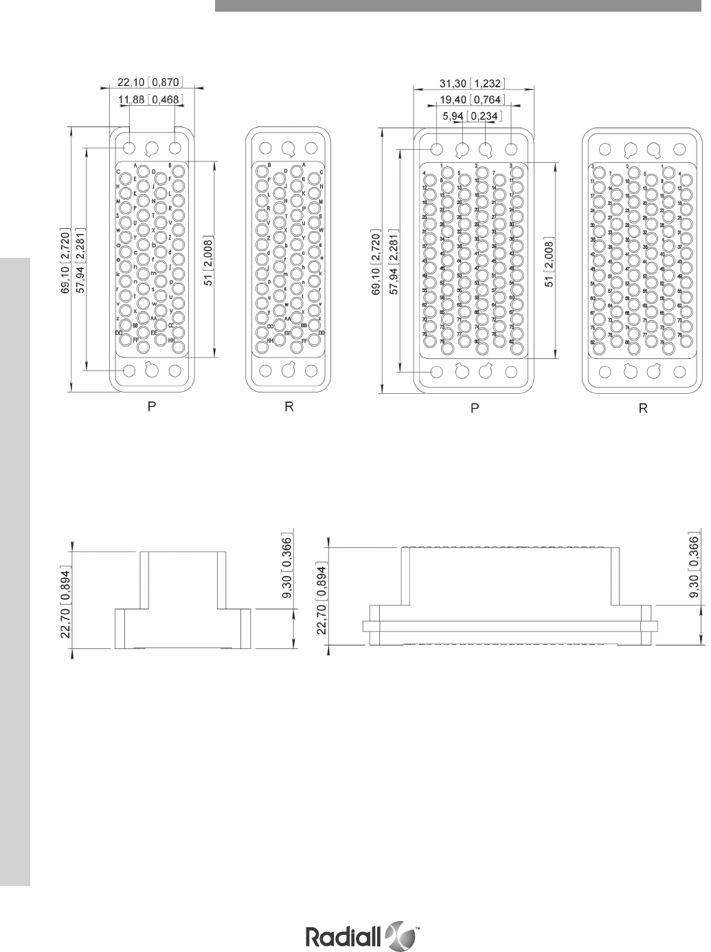
MMC SERIES
50 contacts
VIEW WIRING BLOCK mm (inch)
HEIGHT DIMENSIONS mm (inch)
14, 20, 26, 34, 42 contacts 50, 75 contacts
Contact Arrangements
75 contacts
7-10
Our Most Important Connection is with You.™
Go online for data sheets & assembly instructions Visit www.radiall.com and enter the part number

MMC SERIES
CONNECTOR BLOCK mm (inch)
STRAIN RELIEF CABLE CLAMP (top entry) mm (inch)
Number of contacts A B C
Male Female Male Female
14
10.1 (.397)
34.8 (1.370) 37.2 (1.464) 14.2 (.559) 16.6 (.653)
20 42.2 (1.661) 45.1 (1.775)
26 44.2 (1.740) 46.1 (1.826) 17.3 (.681) 19.4 (.764)
34 10.3 (.405) 54 (2.126) 56.4 (2.220) 22.2 (.874) 24.6 (.968)
42 Shroud not available
50 10.3 (.405) 72 (2.834) 74.6 (2.937) 25.3 (.996) 27.8 (1.094)
75 72.4 (2.850) 74.7 (2.940) 34.4 (1.354) 37 (1.456)
Number of contacts D E Cable entry dimensions
F G max
14
44 (1.732)
31.5 (1.240) 5 (.197) 8 (.315)
20 39.5 (1.555) 12 (.472)
26 41.1 (1.618) 10 (.394)
34 Cable clamp not available
42
50 53 (2.086) 65.6 (2.582) 26 (1.023) 14 (.551)
75 18 (.708)
Rack Guides Dimensions
7-11
Our Most Important Connection is with You.™
Go online for data sheets & assembly instructions Visit www.radiall.com and enter the part number
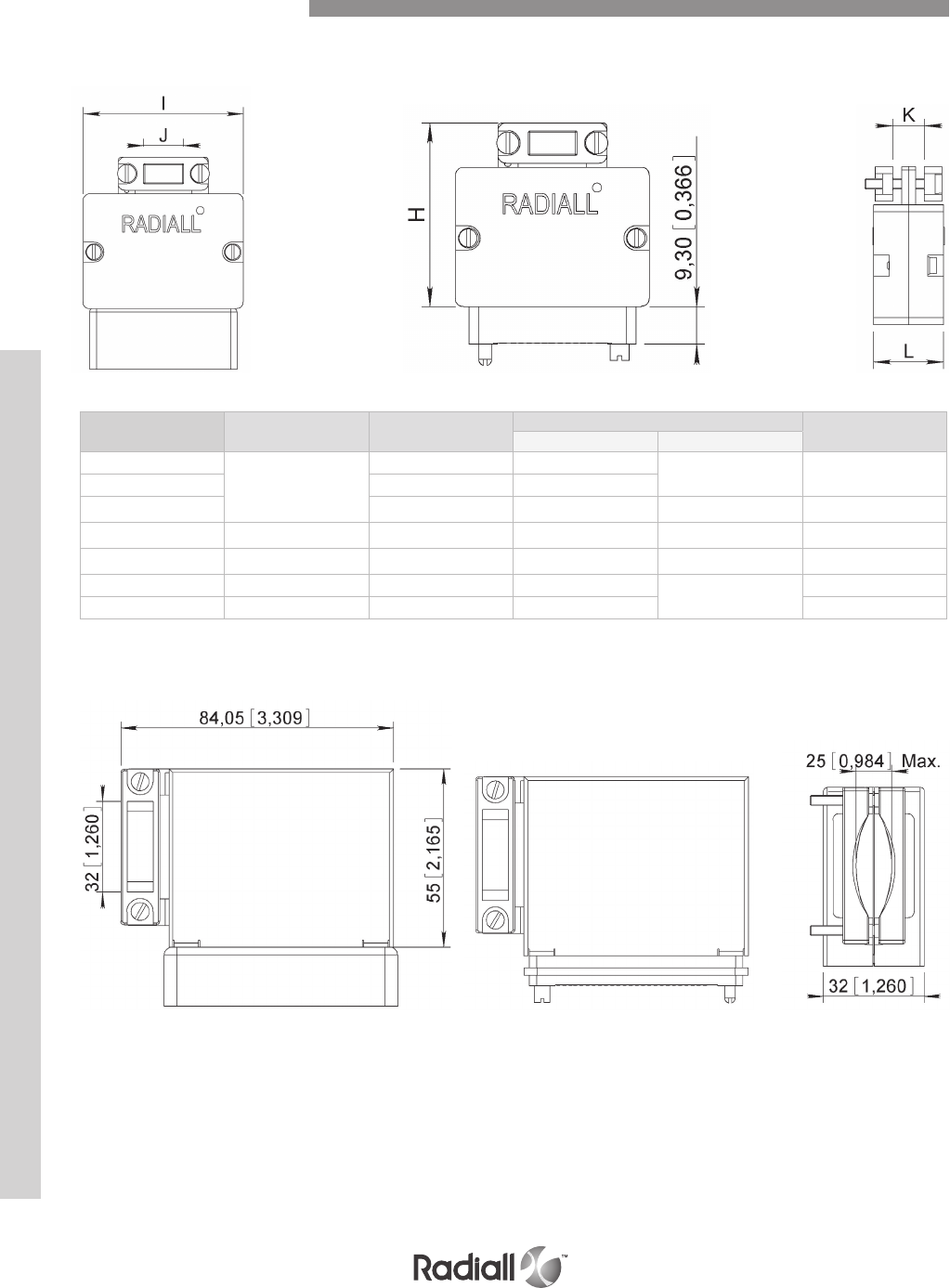
MMC SERIES
BACKSHELL TOP ENTRY - mm (inch)
BACKSHELL SIDE ENTRY - available only for 75 way mm (inch)
Number of contacts H I Cable entry dimensions L
J K max
14
46 (1.811)
39 (1.535) 7.6 (.299) 13 (.512) 17 (.670)
20 47 (1.850) 15 (.590)
26 48.5 (1.909) 17 (.670) 17 (.670) 21 (.827)
34 52.5 (2.067) 53.5 (2.106) 22 (.866) 20 (.787) 24 (.945)
42 47 (1.850) 61 (2.401) 32 (1.260) 12 (.472) 21.5 (.846)
50 66.5 (2.618) 68.5 (2.697) 26 (1.023) 21 (.827) 25 (.984)
75 47 (1.850) 68 (2.677) 40 (1.575) 30.5 (1.200)
Rack Guides Dimensions
7-12
Our Most Important Connection is with You.™
Go online for data sheets & assembly instructions Visit www.radiall.com and enter the part number
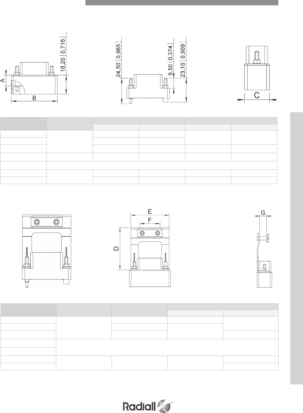
MMC SERIES
STRAIN RELIEF CABLE CLAMP (top entry) mm (inch)
Number of contacts A B C
Male Female Male Female
14
10.1 (.397)
34.8 (1.370) 37.2 (1.464) 14.2 (.559) 16.6 (.653)
20 42.2 (1.661) 45.1 (1.775)
26 44.2 (1.740) 46.4 (1.827) 17.3 (.681) 19.4 (.764)
34 10.3 (.405) 54 (2.126) 56.4 (2.220) 22.2 (.874) 24.6 (.968)
42 Shroud not available
50 10.3 (.405) 72 (2.834) 74.6 (2.937) 25.3 (.996) 27.8 (1.094)
75 72.4 (2.850) 74.7 (2.940) 34.4 (1.354) 37 (1.456)
Number of contacts D E Cable entry dimensions
F G max
14
44 (1.732)
31.5 (1.240) 5 (.197) 8 (.315)
20 39.5 (1.555) 12 (.472)
26 41.1 (1.618) 10 (.394)
34 Cable clamp not available
42
50 53 (2.086) 65.6 (2.582) 26 (1.023) 14 (.551)
75 18 (.708)
CONNECTOR BLOCK mm (inch)
Fixed Jackscrews Dimensions
7-13
Our Most Important Connection is with You.™
Go online for data sheets & assembly instructions Visit www.radiall.com and enter the part number
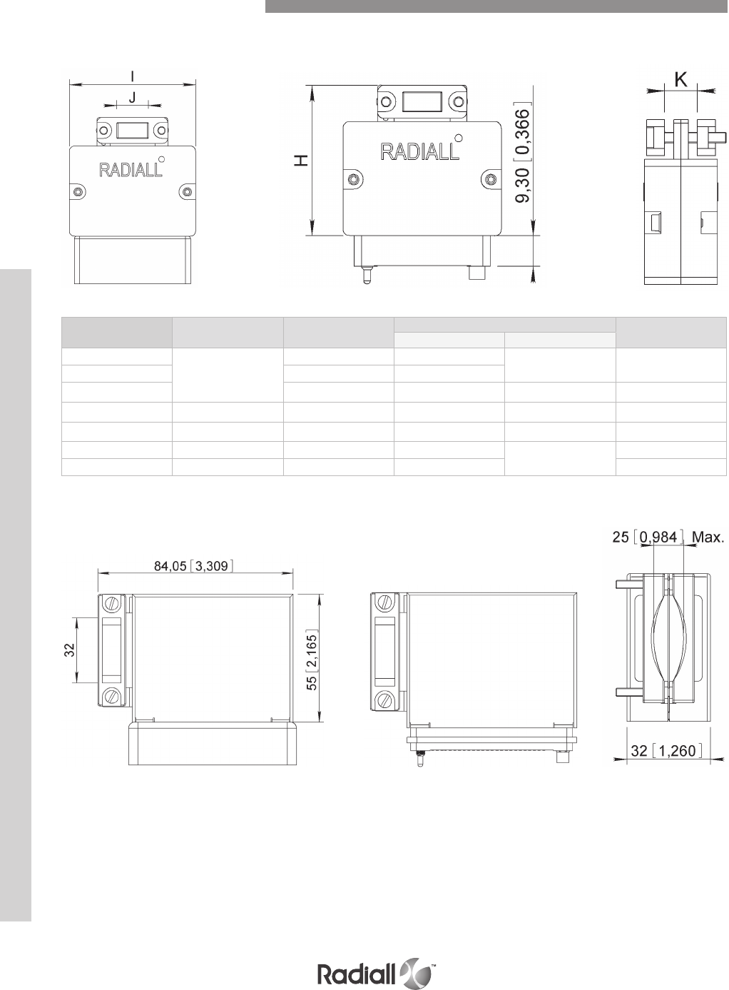
MMC SERIES
BACKSHELL TOP ENTRY - mm (inch)
Number of contacts H I Cable entry dimensions L
J K max
14
46 (1.811)
39 (1.535) 7.6 (.299) 13 (.512) 17 (.670)
20 47 (1.850) 15 (.590)
26 48.5 (1.909) 17 (.670) 17 (.670) 21 (.827)
34 52.5 (2.067) 53.5 (2.106) 22 (.866) 20 (.787) 24 (.945)
42 47 (1.850) 61 (2.401) 32 (1.260) 12 (.472) 21.5 (.846)
50 66.5 (2.618) 68.5 (2.697) 26 (1.023) 21 (.827) 25 (.984)
75 47 (1.850) 68 (2.677) 40 (1.575) 30.5 (1.200)
BACKSHELL SIDE ENTRY - available only for 75 way mm (inch)
Fixed Jackscrews Dimensions
7-14
Our Most Important Connection is with You.™
Go online for data sheets & assembly instructions Visit www.radiall.com and enter the part number
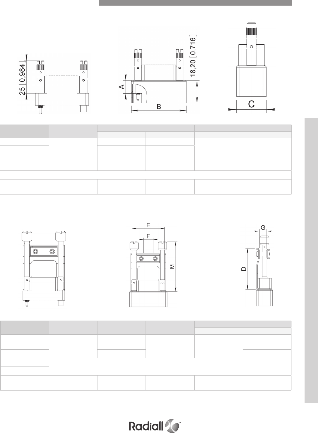
MMC SERIES
STRAIN RELIEF CABLE CLAMP (top entry) mm (inch)
Number of contacts A B C
Male Female Male Female
14
10.1 (.397)
34.8 (1.370) 37.2 (1.464) 14.2 (.559) 16.6 (.653)
20 42.2 (1.661) 45.1 (1.775)
26 44.2 (1.740) 46.4 (1.827) 17.3 (.681) 19.4 (.764)
34 10.3 (.405) 54 (2.126) 56.4 (2.220) 22.2 (.874) 24.6 (.968)
42 Shroud not available
50 10.3 (.405) 72 (2.834) 74.6 (2.937) 25.3 (.996) 27.8 (1.094)
75 72.4 (2.850) 74.7 (2.940) 34.4 (1.354) 37 (1.456)
Number of contacts D E M Cable entry dimensions
F G max
14
44 (1.732)
31.5 (1.240)
60 (2.362)
5 (.197) 8 (.315)
20 39.5 (1.555) 12 (.472)
26 41.1 (1.618) 10 (.394)
34 Cable clamp not available
42
50 53 (2.086) 65.6 (2.582) 64 (2.519) 26 (1.023) 14 (.551)
75 18 (.708)
CONNECTOR BLOCK mm (inch)
Rotating Jackscrews Dimensions
7-15
Our Most Important Connection is with You.™
Go online for data sheets & assembly instructions Visit www.radiall.com and enter the part number
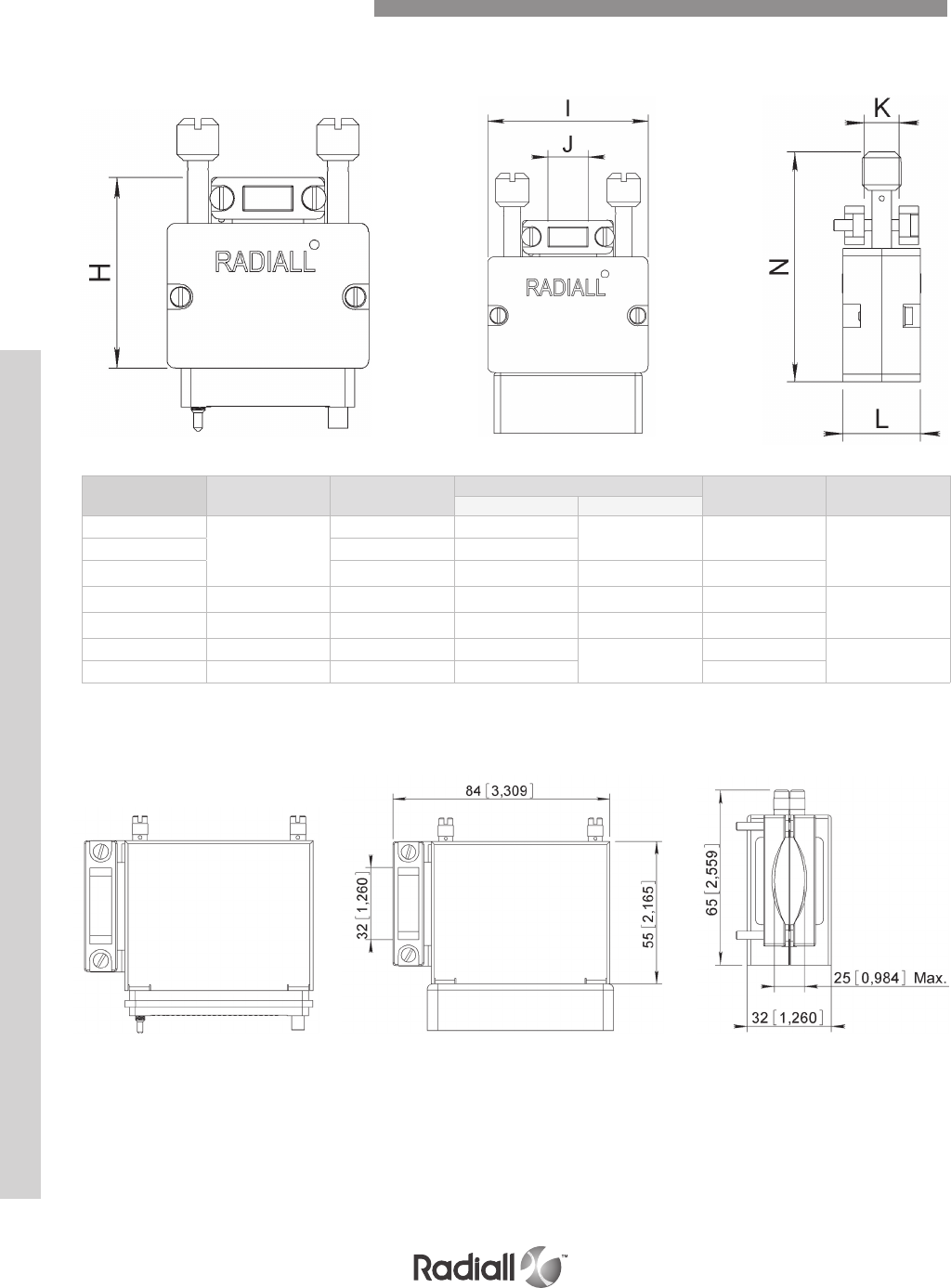
MMC SERIES
BACKSHELL TOP ENTRY mm (inch)
BACKSHELL SIDE ENTRY - available only for 75 way mm (inch)
Number of contacts H I Cable entry dimensions L N
J K max
14
46 (1.811)
39 (1.535) 7.6 (.299) 13 (.512) 17 (.670) 60 (2.362)
20 47 (1.850) 15 (.590)
26 48.5 (1.909) 17 (.670) 17 (.670) 21 (.827)
34 52.5 (2.067) 53.5 (2.106) 22 (.866) 20 (.787) 24 (.945) 64 (2.519)
42 47 (1.850) 61 (2.401) 32 (1.260) 12 (.472) 21.5 (.846)
50 66.5 (2.618) 68.5 (2.697) 26 (1.023) 21 (.827) 25 (.984) 78 (3.071)
75 47 (1.850) 68 (2.677) 40 (1.575) 30.5 (1.200)
Rotating Jackscrews Dimensions
7-16
Our Most Important Connection is with You.™
Go online for data sheets & assembly instructions Visit www.radiall.com and enter the part number
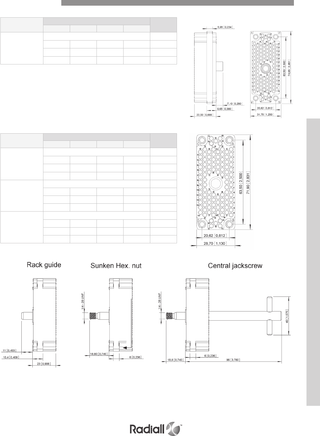
MMC SERIES
Central guide R Type - Rack guides Part
number
A B C D
Mates with all
the blocks P
No guides 690571
Female Male Male Female 690570
Female -- -- Female 690572
Female Female Female Female 690573
Central guide P Type - Rack guides Part
number
A B C D
Central
rack guide
No guides 690481
Male Female Female Male 690480
Male -- -- Male 690482
Male Male Male Male 690483
Sunken
Hex. Nut
4 A/F
No guides 690471
Male Female Female Male 690470
Male -- -- Male 690472
Male Male Male Male 690473
Central
jackscrew
No guides 690476
Male Female Female Male 690475
Male -- -- Male 690477
Male Male Male Male 690478
view wiring side mm (inch)
Block 104 Contacts
7-17
Our Most Important Connection is with You.™
Go online for data sheets & assembly instructions Visit www.radiall.com and enter the part number
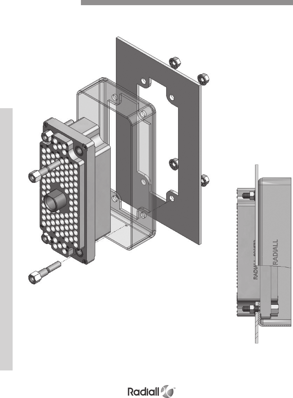
MMC SERIES
Detailed view of the connector with shroud mounted on a panel
Block 104 Contacts
View once all assembled.
7-18
Our Most Important Connection is with You.™
Go online for data sheets & assembly instructions Visit www.radiall.com and enter the part number
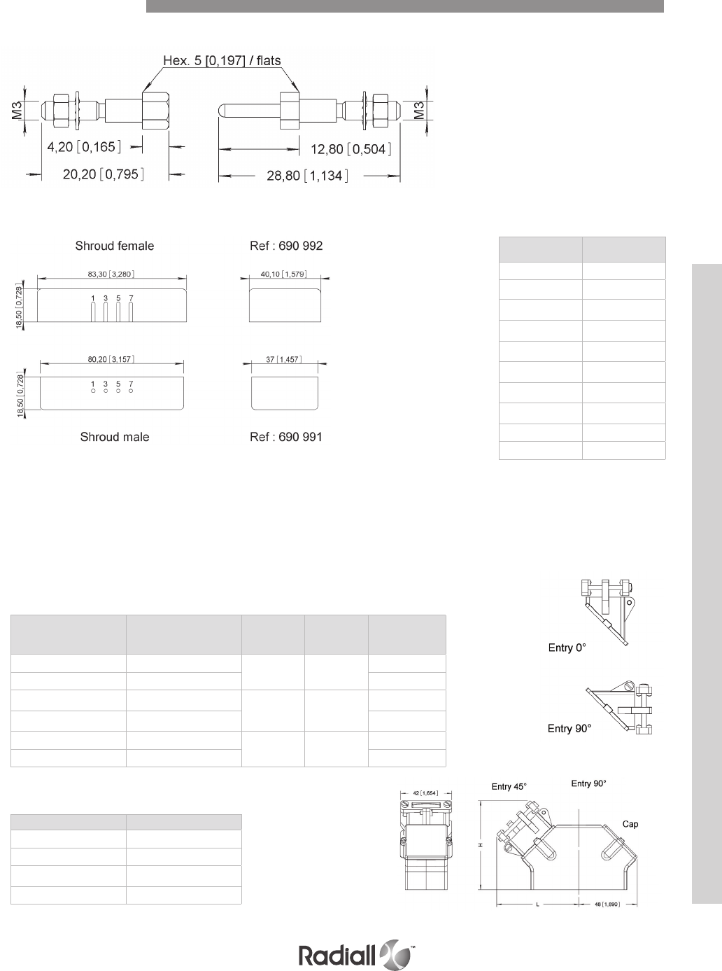
MMC SERIES
GUIDES to mount in positions A, B, C, D
BACKSHELL – cast aluminium painted black
Assembly Kit
SHROUDS
Female shroud - use only this reference to order without polarizing code.
Male shroud - use only this reference to order without polarizing code.
To order with polarizing: add the polarization code at the end of the
shroud part number
see Example: 690991110
SPARE PARTS (1 or 2 entry rotation)
Female P/N 690950 Male P/N 690960
Polarization
Code Position
110 1
120 3
130 5
140 7
210 1 + 3
220 3 + 5
230 5 + 7
240 1 + 5
250 3 + 7
260 1 + 7
Entry
Cable clamp
max. cm_ (inch) L H Part number
1 entry 45° 7.8 (3.1) 70
(27.6)
71
(28)
690971
2 entries 45° 15.6 (6.1) 690972
1 entry 0° 5.3 (2.1) 55
(21.7)
66
(26)
690973
2 entries 0° 10.6 (4.2) 690974
1 entry 90° 5.3 (2.1) 65
(25.6)
57
(22.4)
690973
2 entries 90° 10.6 (4.2) 690974
Description Part number
Body (in 2 parts) 690977
Entry 0 – 90° 690980
Entry 45° 690979
Cap 690978
Block 104 Contacts
7-19
Our Most Important Connection is with You.™
Go online for data sheets & assembly instructions Visit www.radiall.com and enter the part number
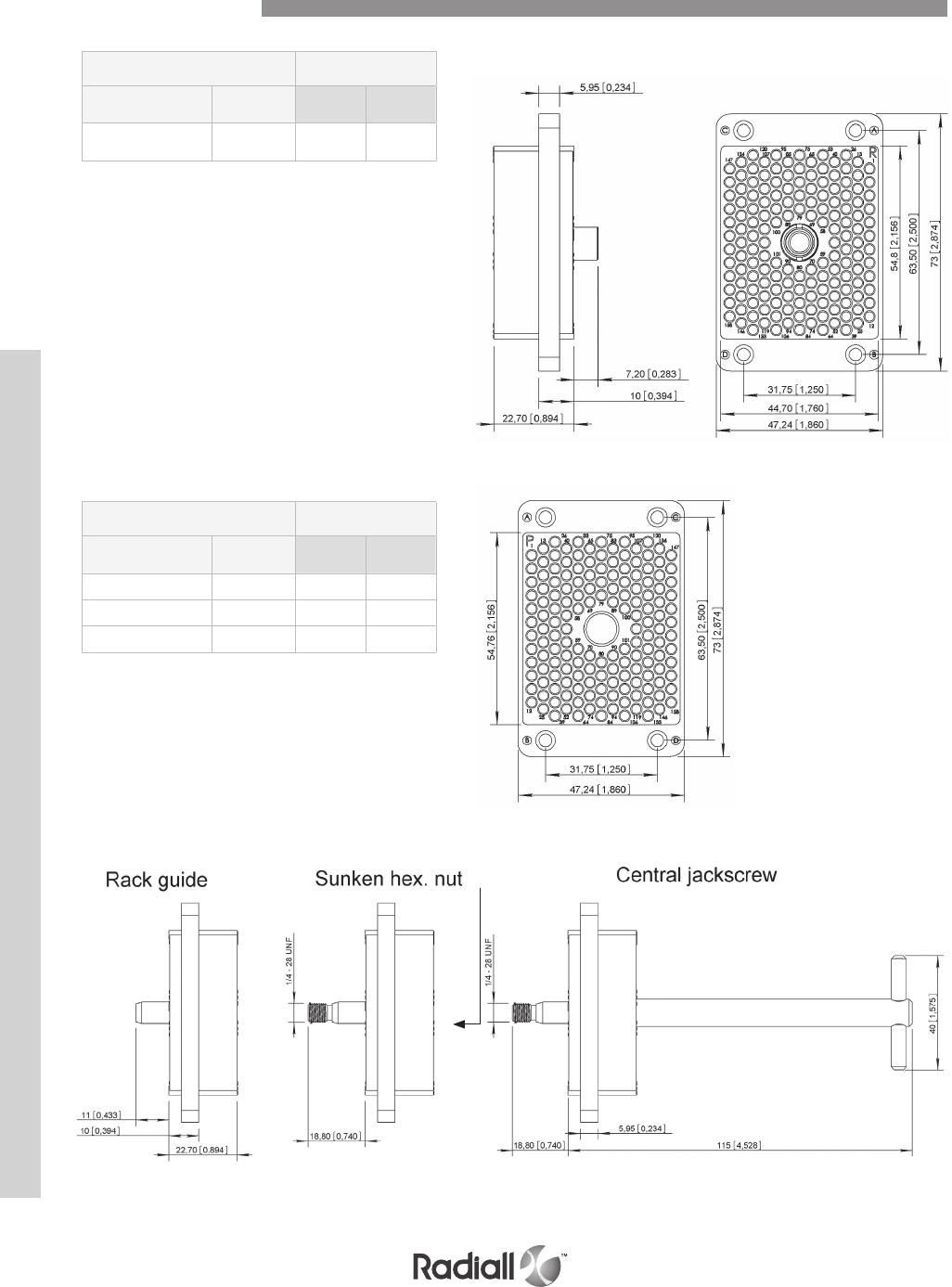
MMC SERIES
R TYPE Guides supplied
unmounted
Central guide Without
guides 4 female 2 male /
2 female
Mates with all
blocks P 690686 690670 690680
P TYPE Guides supplied
unmounted
Central guide Without
guides 4 female 2 male /
2 female
Central rack guide 690681 690678 690683
Sunken Hex. 4 A/F 690671 690679 690684
Central jackscrew 690676 690677 690682
view wiring side mm (inch)
Block 158 Contacts
7-20
Our Most Important Connection is with You.™
Go online for data sheets & assembly instructions Visit www.radiall.com and enter the part number
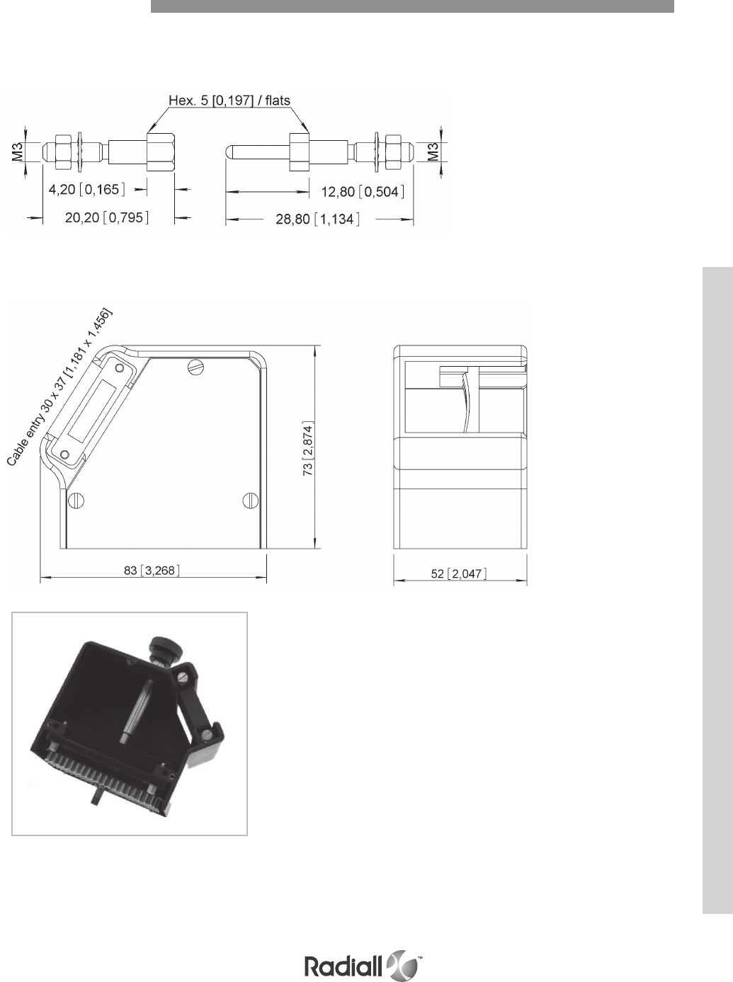
MMC SERIES
GUIDES TO MOUNT IN POSITIONS A, B, C, D - mm (inch)
BACKSHELL P/N 690985 - mm (inch)
Female P/N 690950 Male P/N 690960
Block 158 Contacts
7-21
Our Most Important Connection is with You.™
Go online for data sheets & assembly instructions Visit www.radiall.com and enter the part number
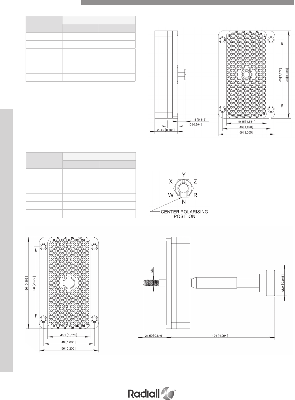
MMC SERIES
Polarizing
positions
Guides supplied unmounted
4 female 2 male / 2 female
N 690768001 690778004
R 690768002 690778007
Z 690768003 690778002
Y 690768004 690778003
X 690768005 690778001
W 690768006 690778005
Polarizing
positions
Guides supplied unmounted
4 female 2 male / 2 female
N 690769001 690767001
R 690769002 690767002
Z 690769003 690767003
Y 690769004 690767004
X 690769005 690767005
W 690769006 690767006
view wiring side mm (inch)
Block 208 Contacts
7-22
Our Most Important Connection is with You.™
Go online for data sheets & assembly instructions Visit www.radiall.com and enter the part number
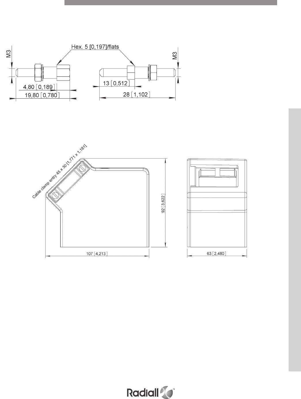
MMC SERIES
GUIDES TO MOUNT IN POSITIONS A, B, C, D - mm (inch)
BACKSHELL P/N 690982 - mm (inch)
Female P/N 690958 Male P/N 690968
Block 208 Contacts
7-23
Our Most Important Connection is with You.™
Go online for data sheets & assembly instructions Visit www.radiall.com and enter the part number
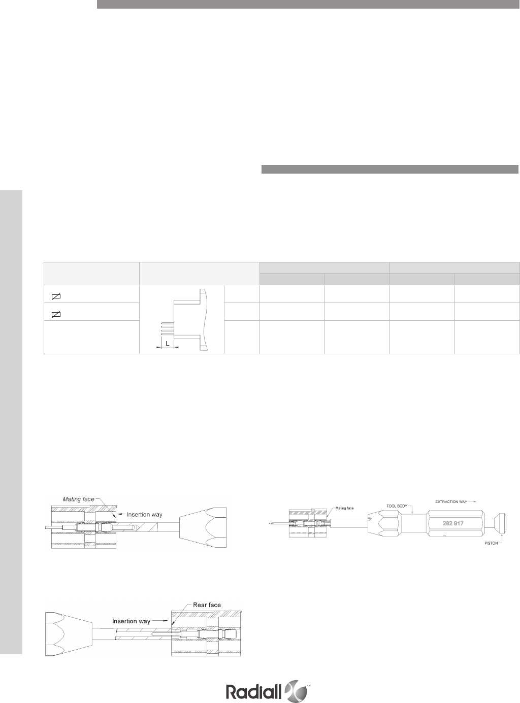
MMC SERIES
Pins and/or sockets for equipment wire, twisted pairs and coaxial cable can be housed in either plug or
receptacle giving a multitude of connection possibilities.
Many contact arrangements available: 14 -20 - 26 - 34 - 42 - 50 - 75 - 104 - 158 and 208 ways.
The signal contacts size 16 (pin Ø 1.58mm) are for crimping to AWG 16 to 28.
Contacts for wire wrapping are available with tails 0.6 x 0.6 mm (0.024x0.024 inch) or 1.2 x 1.2mm (0.047
x 0.047 inch) square. The coaxial contacts are for crimping to 2 mm and 2.6 mm coaxial cables and AWG
24 to 30 twisted pairs.
For all other contact terminations: consult us
No tool is necessary for the insertion, the extraction is from the rear using an extraction tool introduced
by the mating face of the connector.
In order to facilitate the junction of MMC series connectors with a flexible or steady printed
circuits, Radiall created a range of solder tail and wire wrap front release contacts.
This eases the replacement of a damaged contact without rewiring the set.
These size 16 contacts fit with all standard MMC connectors cavities from 14 to 208 which allow
to mix them on a same connector with micro-coaxial contacts and crimping contacts.
Contact Installation
1) Insert the contact fitted with the
retention clip through the mating face
and push insertion tool 282501.
Contact Replacement
Extraction: insert the extraction tool 282917 by
the mating face into the cavity of the contact to be
replaced. Push it until it butts against the contact
shoulder. Maintain the pressure on piston and pull
on body tool to extract the contact. To free the
contact release pressure on piston.
Installation of a new contact without retention clip:
insert the contact through the mating face, push it
with tool 282501 until contact snaps in place.
2) Introduce the sleeve by the rear
face with tool 282502 and push it
until it flushes with the insulator.
INSTALLATION AND EXTRACTION OF FR/FR CONTACTS.
Type Contacts
Arrangements
Contact (1) Replacement contact (2)
Pin Socket Pin Socket
Mini-wrapping
0.6 (.024) flats 2 wraps L=10.6
(.417) 690220 690320 690220001 690320001
Mini-wrapping
0.6 (.024) flats 3 wraps L=16
(.630) 690221 690321 690221001 690321001
PC tail Ø 0.65mm
(.026) L=6.2
(.244) 690222 690322 690222001 690322001
NOTES:
(1) Contact with retention clip and anti-rotation sleeve, must be used for the original or initial equipment of the connectors.
(2) Contact without retention clip and anti-rotation sleeve for the replacement of damaged contacts.
Front Release and Front Removable Contacts
Contacts
7-24
Our Most Important Connection is with You.™
Go online for data sheets & assembly instructions Visit www.radiall.com and enter the part number
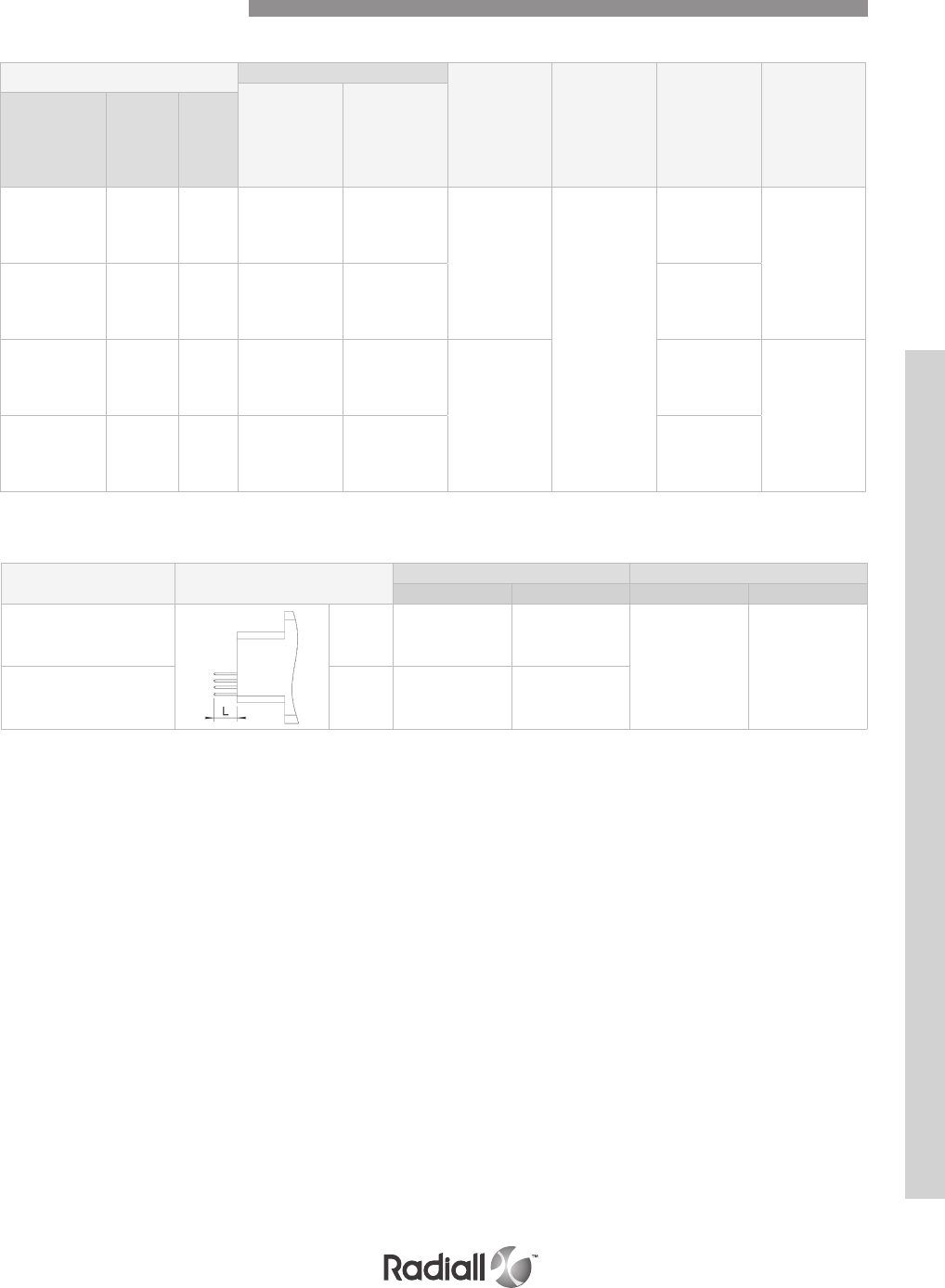
MMC SERIES
FRONT RELEASE / REAR RELEASE CRIMP CONTACTS
CABLES Contacts
Positioner Crimping tool
Position
on crimp
tool
Extraction tool
Pin Socket
AWG
size
Section in
mm2
(sq.in)
Ø max.
on
sleeve
mm
(inch)
16
18
20
1.34 (.053)
0.93 (.037)
0.60 (.024)
3.10
(.122) 690200 690300
282975
282291
M22520/1.01
6
5
4
282920
16
18
20
1.34 (.053)
0.93 (.037)
0.60 (.024)
3.10
(.122) 690201 690301
6
5
4
20
22
24
0.60(.024)
0.38 (.015)
0.22 (.009)
2.20
(.086) 690215 690315
282976
4
3
2
282920
24
26
28
0.22 (.009)
0.14 (.006)
0.093 (.004)
1.60
(.063) 690235 690335
4
2
2
Equipment Signal Contacts
WIRE WRAP CONTACTS
Type Contacts
Arrangements
Contacts Tools
Pin Socket Insertion Extraction
Mini-wrapping
Ø 0.6 (.024) flats 2 wraps
L=10.6
(.417) 690241 690341
282921 282920
Wrapping standard
Ø 1.2 (.047) flats 3 wraps
L=19.5
(.767) 690240 690340
7-25
Our Most Important Connection is with You.™
Go online for data sheets & assembly instructions Visit www.radiall.com and enter the part number
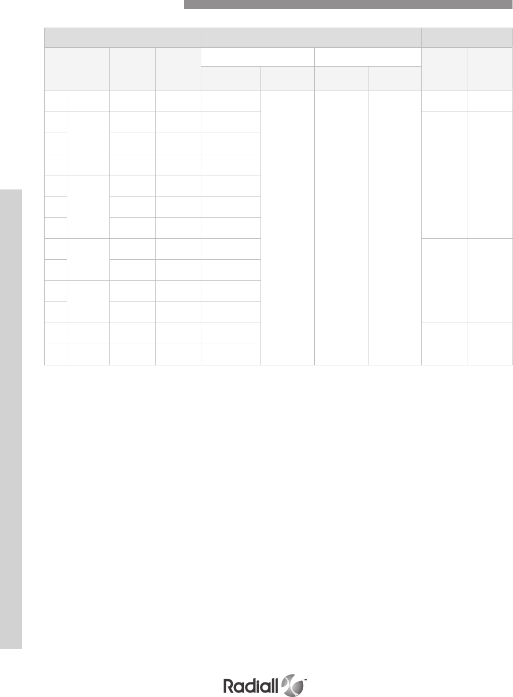
MMC SERIES
CABLES TOOLS (3) CONTACTS &
Wiring Instructions (4)
Center contact Outer contact
Socket (1) Pin (2)
AWG
size
Section in
mm2 (sq.in)
Ø max. on
insulator Position on
crimping tool (5) Positioner Cimping tool Positioner
24 Stranded
wire cable
0.22
(.009)
0.96
(.038) 2
282981 / M22520/2.04
282292 / M22520/4.01
282973 / M22520/4.02
690070
B
690170
B
26
Stranded
wire cable
0.14
(.006)
0.84
(.033) 2
690060
A
690160
A
28 0.093 (.004) 0.73
(.029) 1
30 0.055 (.002) 0.66
(.026) 1
26
Single wire
cable
0.12
(.005)
0.85
(.033) 3
28 0.08
(.003)
0.67
(.026) 2
30 0.05
(.002)
0.58
(.023) 1
26 Stranded
wire cable
0.14
(.006)
0.84
(.033) 2
690061
A
690161
A
28 0.093 (.004) 0.73
(.029) 1
26 Single wire
cable
0.12
(.005)
0.85
(.033) 3
28 0.08
(.003)
0.67
(.026) 2
30 Stranded
wire cable 0.055 (.002) 0.66
(.026) 1690062
A
690162
A
30 Single wire
cable
0.05
(.002)
0.58
(.023) 1
NOTES:
(1) Body female contact / center male contact
(2) Body male contact / center female contact
(3) Extraction tool for all twisted pair contacts P/N 282920
(4) Wiring instructions on pages 7-31 to 7-34
(5) Crimping tool for all 282281 / M22520/2.01
Twisted Pair Crimp Contacts
7-26
Our Most Important Connection is with You.™
Go online for data sheets & assembly instructions Visit www.radiall.com and enter the part number
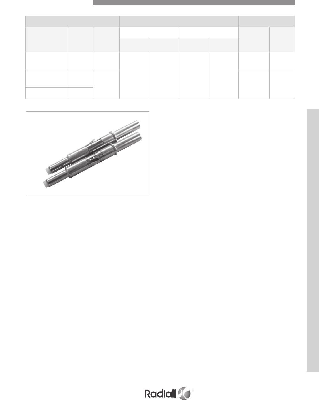
MMC SERIES
NOTES:
(1) Body female contact / center male contact
(2) Body male contact / center female contact
(3) Extraction tool for all twisted pair contacts P/N 282920
(4) Wiring instructions on pages 7-31 to 7-34
Coaxial Crimp Contacts
CABLES TOOLS (3) CONTACTS &
Wiring Instructions (4)
Center contact Outer contact
Socket (1) Pin (2)
Cable reference Impedance
Ω
Outer
diameter Crimp tool Positioner Crimp tool Positioner
RG178/U
RG196/U
KX21
50 2 (.079)
282281
M22520/2.01
282981
M22520/2.04
282292
M22520/4.01
282973
M22520/4.02
690020
C
690120
C
KX3A
RG316/U
KX22
50 2.54 (.100)
± 0.13 (.005)
690040
D
690140
D
RG179/U 75
7-27
Our Most Important Connection is with You.™
Go online for data sheets & assembly instructions Visit www.radiall.com and enter the part number
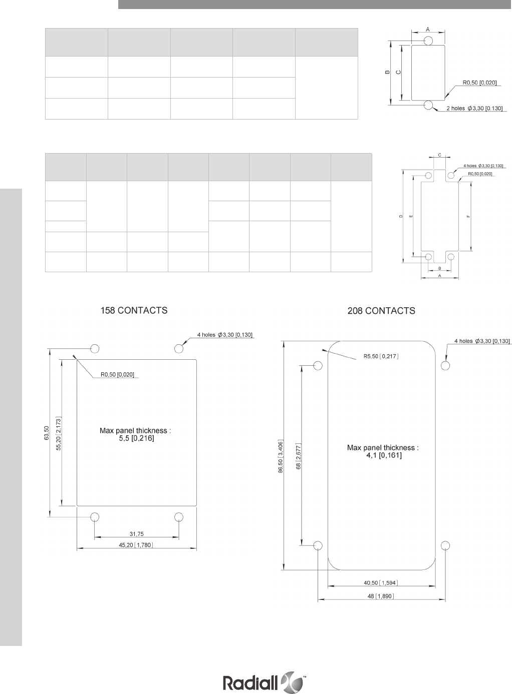
MMC SERIES
Number
of
contacts
A B C
Max.
panel
thickness
14 12.4
(.488)
23.8
(.937)
20.8
(.819)
6
(.236)
20 12.4
(.488)
31.7
(1.248)
28.7
(1.130)
26 15.7
(.618)
33.3
(1.311)
29.2
(1.150)
Number
of
contacts
A B C D E F
Max.
panel
thickness
34
19.8
(.779)
11.9
(.468)
6.3
(.248)
49.3
(1.940)
42.8
(1.685)
36.6
(1.441)
6
(.236)
42 56.9
(2.240)
50.5
(1.988)
43.7
(1.720)
50 64.3
(2.531)
57.9
(2.279)
51.6
(2.031)
75 29
(1.141)
19.4
(.764)
14.2
(.559)
104 29.3
(1.153)
20.6
(.811)
12.7
(.500)
72.5
(2.854)
63.5
(2.500)
55.6
(2.189)
5.5
(.216)
Panel Cut Out
7-28
Our Most Important Connection is with You.™
Go online for data sheets & assembly instructions Visit www.radiall.com and enter the part number
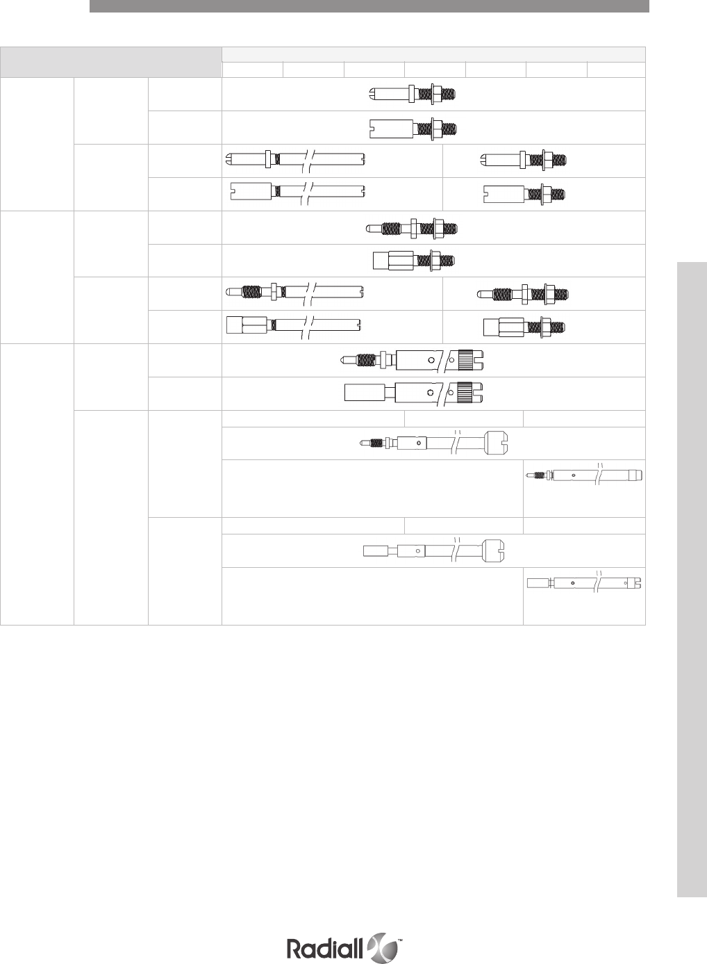
MMC SERIES
Jackscrew and rack guide selection table
Cables Number of contacts
Rack guides
Without
backshell
Male 690962
Female 690952
With
backshell
Male 690963 690963
Female 690963 690963
Fixed guides
Without
backshell
Male 690961
Female 690951
With
backshell
Male 690964 690961
Female 690954 690951
Rotating
jackscrews
Without
backshell
Male 690965
Female 690955
With or
without
backshell
Male
690966 690949 690967
For 75 contacts
690967001 Side entry
Female
690956 690939 690957
For 75 contacts
690957001 Side entry
Spare Parts
14 20 26 34 42 50 75
7-29
Our Most Important Connection is with You.™
Go online for data sheets & assembly instructions Visit www.radiall.com and enter the part number
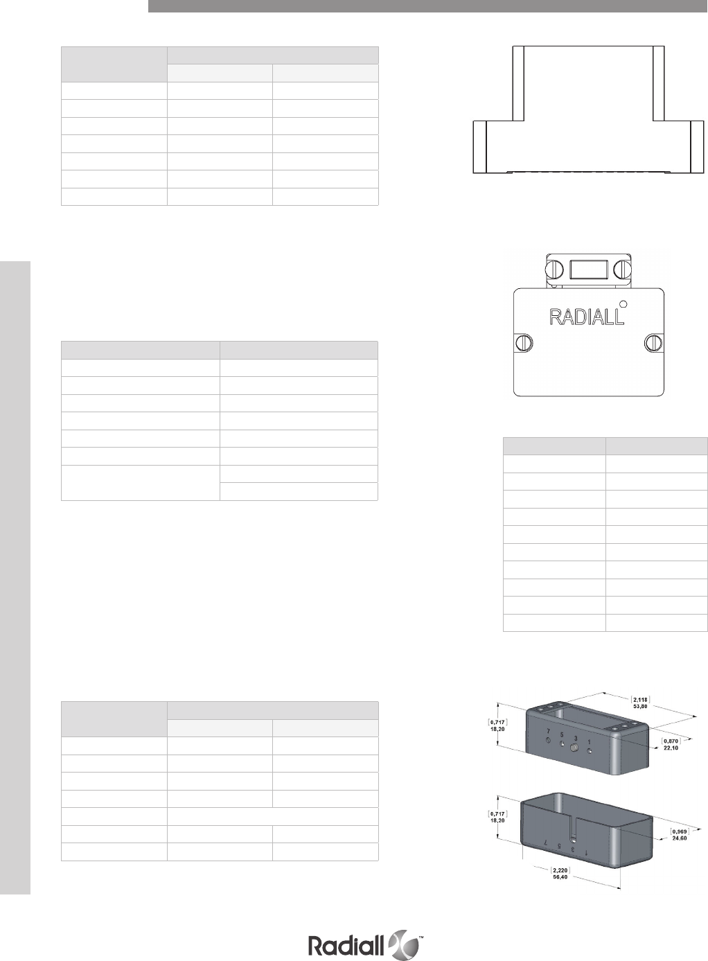
MMC SERIES
INSULATOR BLOCKS ONLY
Number of
contacts
Block
Type P Type R
14 690401 690501
20 690411 690511
26 690421 690521
34 690431 690531
42 690441 690541
50 690451 690551
75 690461 690561
BACKSHELLS
Number of contacts Backshell reference
14 690905
20 690908
26 690911
34 690914
42 690917
50 690920
75 Type P 690923
Type R 690924
Male shroud is to be mounted on insulator block
P and female shroud on insulator block R.
Polarizing is to be positioned next to cavity
1 or A of the insulator block.
To order without polarization just use the six digits
in the following table. To include polarization
add the 3 digits suffix following the 6 digits
part number. E.G: 690943120 (position 3).
Number of contacts Shrouds
Male Female
14 690940 690930
20 690941 690931
26 690942 690932
34 690943 690933
42 Not available
50 690945 690935
75 690946 690936
Polarization code Position
110 1
120 3
130 5
140 7
210 1 + 3
220 3 + 5
230 5 + 7
240 1 + 5
250 3 + 7
260 1 + 7
Spare Parts
When ordering backshells separately,
do not forget to order the appropriate
guides or jackscrews (refer to previous
page for part numbers.)
SHROUDS
7-30
Our Most Important Connection is with You.™
Go online for data sheets & assembly instructions Visit www.radiall.com and enter the part number
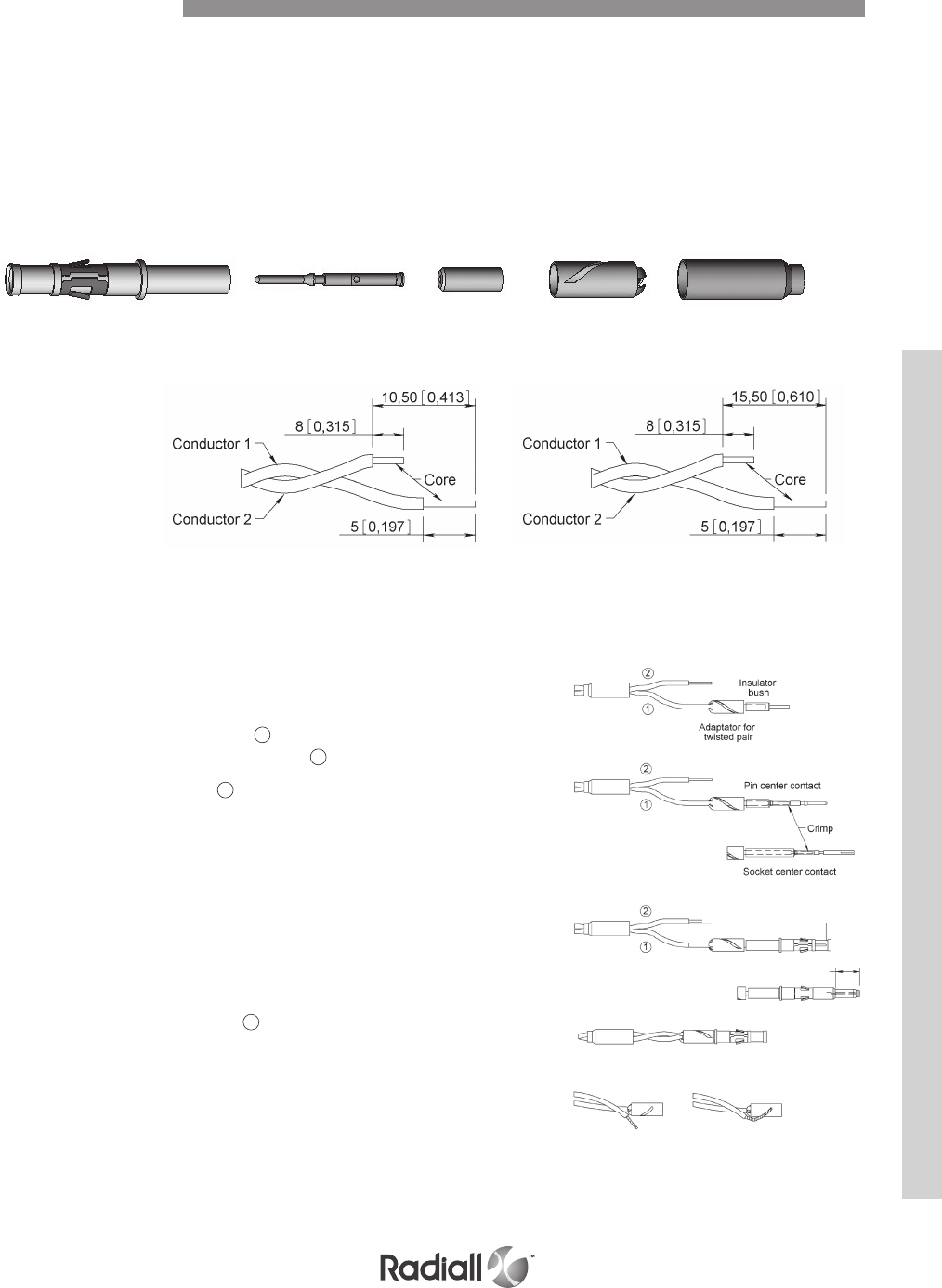
MMC SERIES
TWISTED PAIR CONTACT
2 – Wiring Instructions
- Slide the ferrule over the twisted pair cable
- Following the type of contact, strip the 2 conductors
to the shown dimensions here above
- Slide adaptor over conductor 1
- Slide insulator bush over conductor 1
- Put the core of the cable 1 into the center contact (pin
or socket) until it butts against the insulator bush.
- Engage the assembly (cable + center contact) into
the positioner of the crimping tool, and crimp center
contact according to setting instructions page 7-26.
- Engage the center contact into the body, with reasonable
force push home. Check the dimensional position,
following type of centre contact (pin/socket).
- Slide the adaptor on to the body up to the shoulder.
- Place the core of conductor 2 under the adaptor
tab, and slide core into the helical slot.
- Slide the ferrule over the adapter up
to the shoulder of the body.
- Engage the assembly into the positioner
of the crimping tool, then crimp according
to setting instructions, page 7-26.
1 - Wire Stripping
SOCKET CONTACT PIN CONTACT
Body Center contact Insulator bush Adaptor Ferrule
1 ±0,40 [0,039 ±0,002]
5,9 ±0,40 [0,232 ±0,002]
Wiring Instructions
CONTACT REF: 690060 WIRE SIZES
690160 AWG 26
690061 AWG 28
690161 AWG 30
690062
690162
Wiring Instructions A
7-31
Our Most Important Connection is with You.™
Go online for data sheets & assembly instructions Visit www.radiall.com and enter the part number
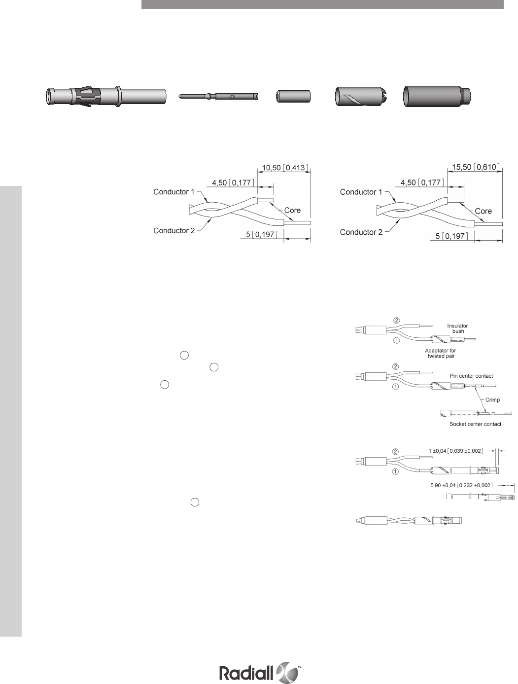
MMC SERIES
TWISTED PAIR CONTACT
2 – Wiring Instructions
- Slide the ferrule over the twisted pair cable
- Following the type of contact, strip the 2 conductors
to the shown dimensions here above
- Slide adaptor over conductor 1
- Slide insulator bush over conductor 1
- Put the core of the cable 1 into the center contact (pin
or socket) until it butts against the insulator bush.
- Engage the assembly (cable + center contact) into
the positioner of the crimping tool, and crimp center
contact according to setting instructions page 7-26.
- Engage the center contact into the body, with reasonable
force push home. Check the dimensional position,
following type of centre contact (pin/socket).
- Slide the adaptor on to the body up to the shoulder.
- Place the core of the conductor 2 into the
straight slot, on the outer face of the adaptor.
- Slide the ferrule over the adapter up
to the shoulder of the body.
- Engage the assembly into the positioner
of the crimping tool, then crimp according
to setting instructions, page 7-26.
1 - Wire Stripping
SOCKET CONTACT PIN CONTACT
Body Center contact Insulator bush Adaptor Ferrule
1 ±0,40 [0,039 ±0,002]
5,9 ±0,40 [0,232 ±0,002]
Wiring Instructions
CONTACT REF: 690070 WIRE SIZE AWG 24
690170
Cabling Instructions B
7-32
Our Most Important Connection is with You.™
Go online for data sheets & assembly instructions Visit www.radiall.com and enter the part number

MMC SERIES
COAXIAL CONTACTS
2 – Wiring Instructions
- Slide the ferrule over the coaxial cable.
- Following the type of contact, strip the 2
conductors to dimensions shown above.
- Comb the braid and slide on the insulator bush
until it butts against the dielectric of the cable.
- Place the core of the cable into the center
contact so as to butt against the dielectric.
- Engage the assembly into the positioner of
the crimping tool and crimp according to
instructions indicated on page 7-27.
- Engage the centre contact into the body and with
reasonable force push home, check the dimensional
position of the centre contact (pin or socket).
- Pull down the braid over the body and slide the
ferrule on to the body up to the shoulder.
- Engage the assembly into the positioner of
the crimping tool, then crimp according to
instructions indicated on page 7-27.
1 - Wire Stripping
SOCKET CONTACT PIN CONTACT
Body Center contact Insulator bush Ferrule
1 ±0,40 [0,039 ±0,002]
5,9 ±0,40 [0,232 ±0,002]
Wiring Instructions
CONTACT REF: 690020
690120
Cabling Instructions C
7-33
Our Most Important Connection is with You.™
Go online for data sheets & assembly instructions Visit www.radiall.com and enter the part number
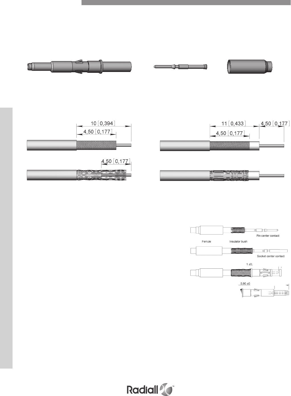
MMC SERIES
COAXIAL CONTACTS
2 – Wiring Instructions
- Slide the ferrule over the coaxial cable.
- Following the type of contact, strip the 2
conductors to dimensions shown above.
- Place the core of the cable into the center contact
so as to butt against the dielectric.
- Engage the assembly into the positioner of the crimping tool,
then crimp according to instructions indicated on page 7-27.
- Engage the center contact into the body and with
reasonable force push home, check the dimensional
position of the center contact (pin or socket).
- Pull down the braid over the body and slide
ferrule over braid up to the body shoulder.
- Engage the assembly into the positioner of the crimping tool,
then crimp according to instructions given on page 7-27.
1 - Wire Stripping
SOCKET CONTACT PIN CONTACT
Body Center contact Ferrule
1 ±0,40 [0,039 ±0,002]
5,9 ±0,40 [0,232 ±0,002]
Wiring Instructions
Cabling Instructions D
CONTACT REF: 690040
690140
7-34
Our Most Important Connection is with You.™
Go online for data sheets & assembly instructions Visit www.radiall.com and enter the part number
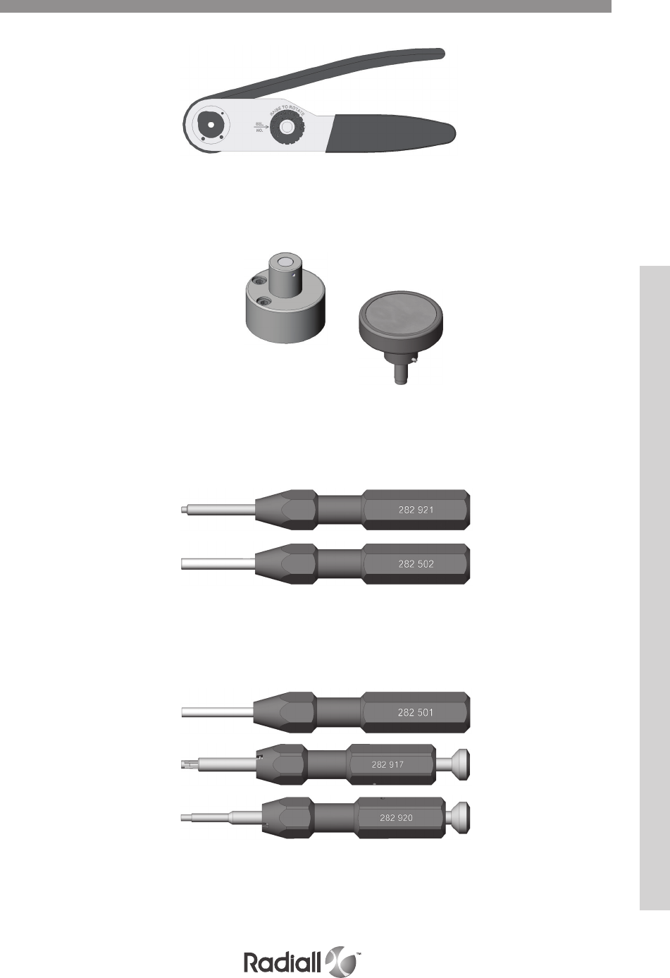
MMC SERIES
CRIMP TOOLS
282281 – M22520/2-01
282291 – M22520/1-01
282292 – M22520/4-01
POSITIONERS
282973 – M22520/4-02
282976 – Daniels TP616
282975 – Daniles TP617
282981 – M22520/2-04
INSERTION TOOL
282502
282921 – wire wrap
EXTRACTION TOOL
282501
282917
282920
Tools
7-35
Our Most Important Connection is with You.™
Go online for data sheets & assembly instructions Visit www.radiall.com and enter the part number

MMC SERIES
Notes
7-36
Our Most Important Connection is with You.™
Go online for data sheets & assembly instructions Visit www.radiall.com and enter the part number
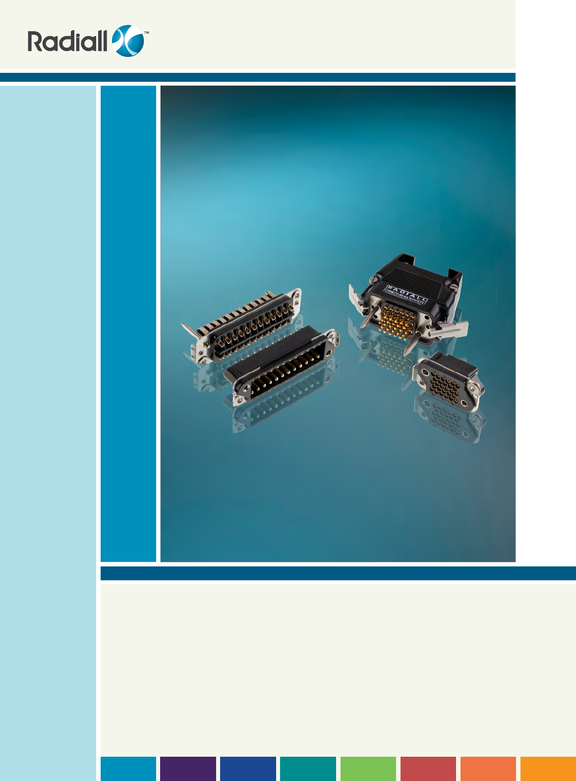
SECTION 8
B & MCS-R Series

Our Most Important Connection is with You.™

SECTION 8 TABLE OF CONTENTS
B Series
Introduction .................................................................................................................. 8-4
Features ...................................................................................................................... 8-4
Applications .................................................................................................................. 8-4
Product overview ............................................................................................................ 8-5
Technical characteristics ................................................................................................... 8-6
How to order connectors ........................................................................................... 8-7 to 8-9
Dimensions .................................................................................................................. 8-10
Panel cut-outs .............................................................................................................. 8-10
MCS-R Series
Introduction ................................................................................................................. 8-11
Features ..................................................................................................................... 8-11
Applications ................................................................................................................. 8-11
Product overview ........................................................................................................... 8-12
Technical characteristics ......................................................................................... 8-13 & 8-14
How to order connectors .................................................................................................. 8-15
Contacts part numbers .................................................................................................... 8-16
Dimensions .................................................................................................................. 8-17
Panel cut-outs .............................................................................................................. 8-17
Contact references ......................................................................................................... 8-18
Locking system code VP ................................................................................................... 8-19
Connectors mounting plates ............................................................................................. 8-20
Connectors accessories .......................................................................................... 8-21 & 8-22
Micro coaxial contacts assembly instructions ......................................................................... 8-23
Tools ......................................................................................................................... 8-24
Contents
8-3
Our Most Important Connection is with You.™
Go online for data sheets & assembly instructions Visit www.radiall.com and enter the part number
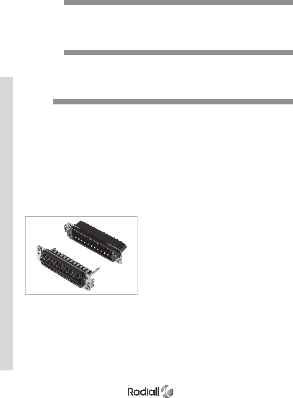
B SERIES
The B series connectors are of robust design with fixed solder pot contacts of 15 A
current rating. They are available in four different contact arrangements.
By their ruggedness, they are particularly suitable for rack and panel and cable to panel applications.
Introduction
The series B connectors ensures complete safety for the following applications:
Industries, transports, communications, power equipment and
all specific civil and military electronic systems.
Applications
Plug and receptacle connectors are made of a thermoset insulator moulded onto a stainless
steel fixing plate. Four contact arrangements are available, 8, 14, 24 and 32 contacts.
The receptacle box type connectors are fitted with round pin contacts. The plug connectors
are fitted with spring blade contacts and two stainless steel guide pins of different diameter
providing polarization and mating before the contacts to ensure correct alignment.
The pin contacts are in silver plated brass, the spring blade contacts are in
silver plated bronze. The cambered configuration and elasticity procures a
self wiping condition at each mating, ensuring high reliability.
The B series connector is only available with solder pot termination for gauge 16 wires. Standard
receptacle connectors are fitted with floating eyelets, which allows 0.75 mm radial float.
Features
8-4
Our Most Important Connection is with You.™
Go online for data sheets & assembly instructions Visit www.radiall.com and enter the part number
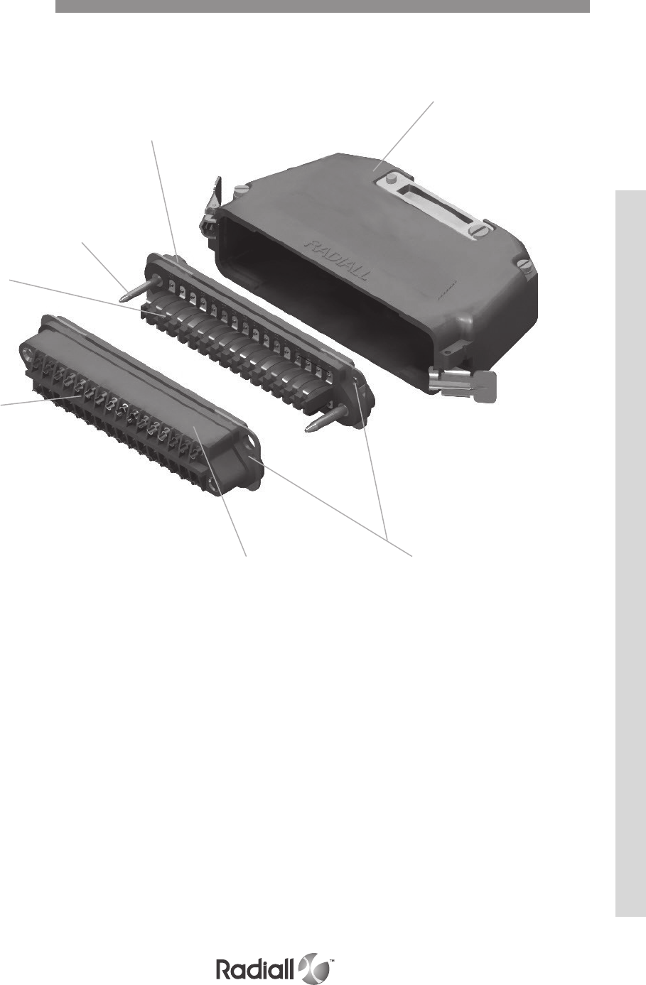
B SERIES
Detailed view of the various parts of this series connector
Plug
Spring blade
contacts
Guide pin
Fixing plates
Receptacle
Top entry backshell
Solder pot
contacts
Product Overview
8-5
Our Most Important Connection is with You.™
Go online for data sheets & assembly instructions Visit www.radiall.com and enter the part number

B SERIES
ELECTRICAL
Current rating by contact: 15 A
Test voltage:
- Between contacts: > 1500 V.r.m.s.
- Between contacts and earth: > 2000 V.r.m.s
Insulation resistance: > 5000 MΩ
Contact resistance: < 10 mΩ
MECHANICAL & ENVIRONMENTAL
Temperature range: -55°C (-131°F) to +125°C (+257°F)
Humidity: 21 days
Mating & unmating: 500 cycles
Contact retention: > 50 N
Technical Characteristics
Description Material / Finish
Insulator block Glass filled phenolic
Pin contacts (male) Brass - silver plated
Spring blade contacts (female) Bronze - silver plated
Guide pins Stainless steel
Fixing plate Stainless steel
MATERIALS
Plug
Contact
Arrangement 08 14 24 32
Weight 35 (1.25) 50 (1.80) 70 (2.50) 85 (3)
Receptacle
Contact
Arrangement 08 14 24 32
Weight 35 (1.25) 50 (1.80) 70 (2.50) 85 (3)
Backshells
Side entry 170 (6) 190 (6.70) 265 (9.35) 300 (10.60)
Top entry 180 (6.35) 200 (7.05) 280 (9.90) 320 (11.30)
MASSES g (oz)
8-6
Our Most Important Connection is with You.™
Go online for data sheets & assembly instructions Visit www.radiall.com and enter the part number

B SERIES
The following indications are to help you out when ordering B connectors.
When a receptacle connector is ordered with the locking system, in place of the floating
eyelets, brackets are fitted whilst the locking clips are always fitted on the backshell.
For backshell and accessories please refer to pages 8-21 to 8-22 for ordering.
The plug connector is fitted with spring leaf contacts and the receptacle box type connector with pin contacts.
B 24 M 71 NV
Series prefix
Contact arrangement
08 – 14 – 24 - 32
Product type
M: Plug connector
F: Receptacle connector(2)
Termination style (1)
71: Ø2.30 solder pot
73: Ø3.20 solder pot
74: PC Tail
75: 5 mm terminal blade
78: NFC 20120 terminal blade
80: Screw cup termination
Modification code
NV: Without locking
VP: Brackets for locking system receptacle only (see page 8-20 for details)
CONNECTOR PART NUMBER
NOTES:
(1) Please refer to page 8-8 for views of termination styles.
(2) Receptacle connector: only the 71 termination style is available
How to Order Connectors
8-7
Our Most Important Connection is with You.™
Go online for data sheets & assembly instructions Visit www.radiall.com and enter the part number

B SERIES
Style 71 Style 73
Style 78 Style 80
Style 74 Style 75
Following are the different termination styles available in details
Termination Styles
8-8
Our Most Important Connection is with You.™
Go online for data sheets & assembly instructions Visit www.radiall.com and enter the part number

B SERIES
8 CONTACTS
14 CONTACTS
24 CONTACTS
32 CONTACTS
Contact Arrangements
8-9
Our Most Important Connection is with You.™
Go online for data sheets & assembly instructions Visit www.radiall.com and enter the part number
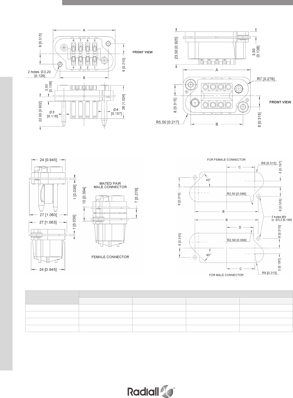
B SERIES
SINGLE SHELL DIMENSIONS
MATED SHELL DIMENSIONS PANEL CUT OUTS
Contact
Arrangement
Plug & receptacle connector dimensions mm(inch)
A B C D
08 48.5 (1.909) 37.5 (1.476) 15.75 (0.620) 15.5 (0.610)
14 65 (2.559) 54 (2.125) 24 (0.944) 23.5 (0.925)
24 92.5 (3.641) 81.5 (3.208) 37.75 (1.486) 37.5 (1.476)
32 114.5 (4.507) 103.5 (4.074) 48.75 (1.919) 48.5 (1.909)
Male Female
Dimensions
mm(inch)
8-10
Our Most Important Connection is with You.™
Go online for data sheets & assembly instructions Visit www.radiall.com and enter the part number

B SERIES
Notes
8-11
Our Most Important Connection is with You.™
Go online for data sheets & assembly instructions Visit www.radiall.com and enter the part number
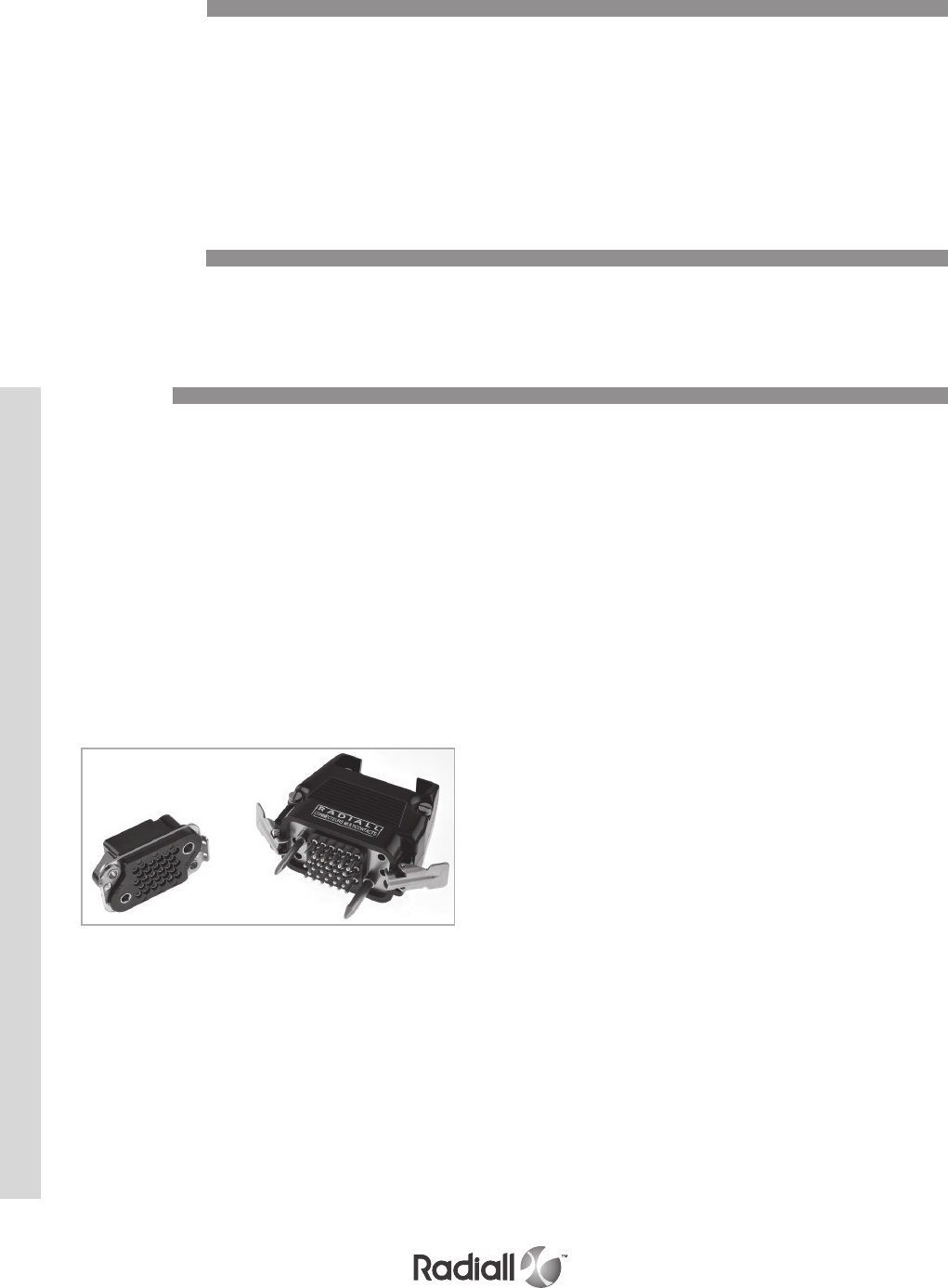
MCS-R SERIES
The MCSR series connectors are of robust design and available in four contacts
arrangements, respectively 28, 48, 83 and 113 wire contacts, size gauge 16.
The same number of micro coaxial contacts can be installed instead of the wired contacts.
A unique feature of the MCSR connector is that it’s interchangeable
with the B series, however, it is not fully intermateable.
The connectors may be adapted with die cast aluminium hoods, with two
types of cable entries, either from the top or from the side.
MCSR connectors are suitable for various applications in the following industrial fields: Communications
and automation systems, electronic equipment, naval, aerospace, and defense applications.
The MCS-R series, plug and receptacle connectors are made of a thermostat insulator moulded onto
a stainless steel fixing plate. Four contact arrangements are available, 28, 48, 83 and 113 contacts.
The plug connector is fitted with two guide pins of different diameter, which provides
polarization and mate before the contacts ensuring a perfect alignment and reliability.
The plug connector accepts socket wire contacts or pin micro coaxial contacts.
The receptacle connector accepts pin wire contacts or socket micro coaxial contacts
and is fitted with floating eyelets which allows 0.75 mm radial float.
Three termination styles on the contacts are available, wire contacts with solder pot
or crimp for wire size gauge 16 and micro coaxial contacts, crimp style.
Introduction
Applications
Features
8-12
Our Most Important Connection is with You.™
Go online for data sheets & assembly instructions Visit www.radiall.com and enter the part number
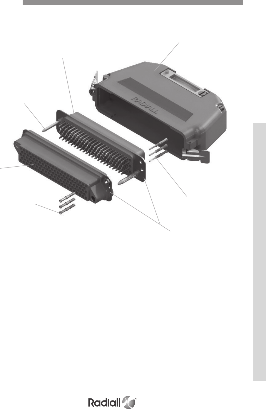
MCS-R SERIES
Plug
Guide pin
Fixing plates
Pin contacts
Top entry backshell
Receptacle
Socket
contacts
Detailed view of the various parts of this series connector
Product Overview
8-13
Our Most Important Connection is with You.™
Go online for data sheets & assembly instructions Visit www.radiall.com and enter the part number

MCS-R SERIES
ELECTRICAL
Current rating by contact: 13 A
Operating voltage: 350 V.r.m.s @ 50 Hz
Test voltage: 1500 V.r.m.s @ 50 Hz
Insulation resistance: > 5000 MΩ
Contact resistance: < 12 mΩ
ELECTRICAL WITH MICRO COAXIAL CONTACTS
Impedance: 50 Ω
Operating frequency range: 0 to 1000 MHz
VSWR of pair of contacts: < 1.4 from 0 to 1000 MHz
Insertion loss of a pair of contacts @ 1000 MHz: < 0.20dB
Test voltage at sea level (mated pair): 600 V.r.m.s @ 50Hz
Insulation resistance: > 5000 MΩ
Contact resistance: < 12 mΩ
MECHANICAL & ENVIRONMENTAL
Temperature range: -55°C (-131°F) to +125°C (+257°F)
Humidity: 21 days
Mating & unmating: 500 cycles
Contact retention: > 50 N
Technical Characteristics
8-14
Our Most Important Connection is with You.™
Go online for data sheets & assembly instructions Visit www.radiall.com and enter the part number
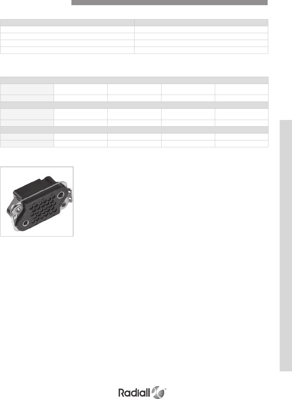
MCS-R SERIES
Description Material / Finish
Insulator block Glass filled phenolic
Guide pins Stainless steel
Fixing plate Stainless steel
Contacts Copper alloy – gold over nickel plated
MATERIALS
Plug
Contact
Arrangement 28 48 83 113
Weight 40 (1.45) 60 (2.15) 90 (3.20) 115 (4.05)
Receptacle
Contact
Arrangement 28 48 83 113
Weight 40 (1.45) 55 (1.95) 85 (3) 110 (3.90)
Backshells
Side entry 170 (6) 190 (6.70) 265 (9.35) 300 (10.60)
Top entry 180 (6.35) 200 (7.05) 280 (9.90) 320 (11.30)
MASSES g (oz)
Technical Characteristics
8-15
Our Most Important Connection is with You.™
Go online for data sheets & assembly instructions Visit www.radiall.com and enter the part number
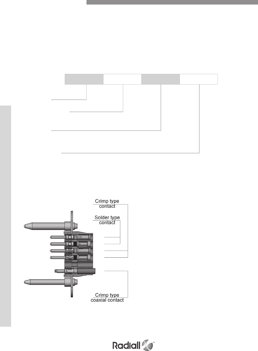
MCS-R SERIES
The following indications are useful when ordering MCS-R connectors.
When ordering a connector with its locking system VP, brackets fitted on the female connector
replace the eyelets, whilst the locking clips are always fitted on the backshell.
Series MCS-R contacts are removable. Contacts shall be ordered separately
following the termination style and quantities desired.
For backshells and accessories please refer to page 8-21 to 8-22 for ordering
For contact references please refer to page 8-18
MCSR 028 M 00
Series prefix
Contact arrangement
028 – 048 – 083 - 113
Product type
M: plug connector
F: receptacle connector
Modification code
00: without locking
VP: brackets for locking system receptacle only (see page 8-19 for detail)
TERMINATION STYLES
How to Order Connectors
8-16
Our Most Important Connection is with You.™
Go online for data sheets & assembly instructions Visit www.radiall.com and enter the part number
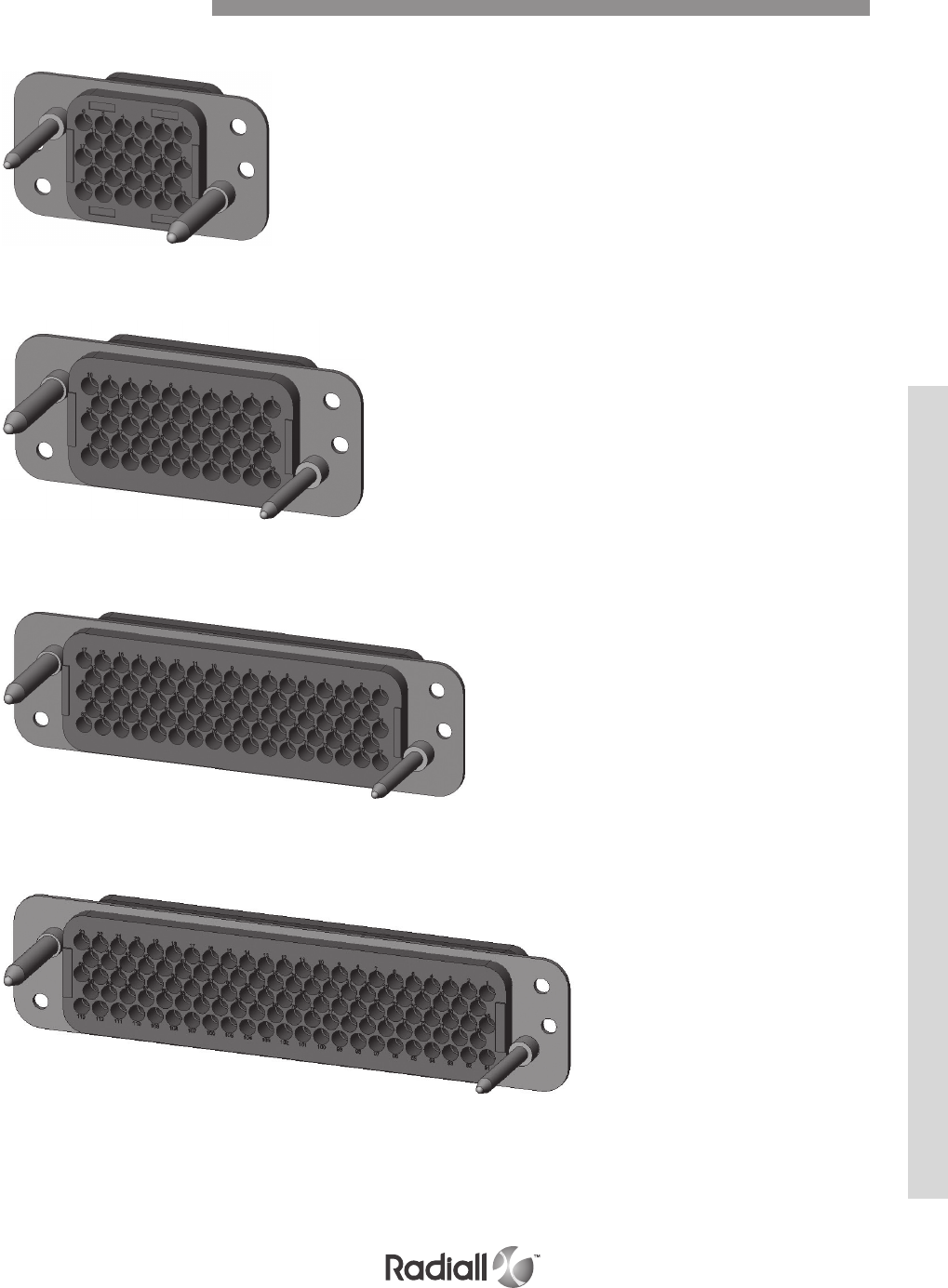
MCS-R SERIES
28 contacts
PLUG VIEW SHOWN
48 contacts
83 contacts
113 contacts
Contact Arrangements
8-17
Our Most Important Connection is with You.™
Go online for data sheets & assembly instructions Visit www.radiall.com and enter the part number
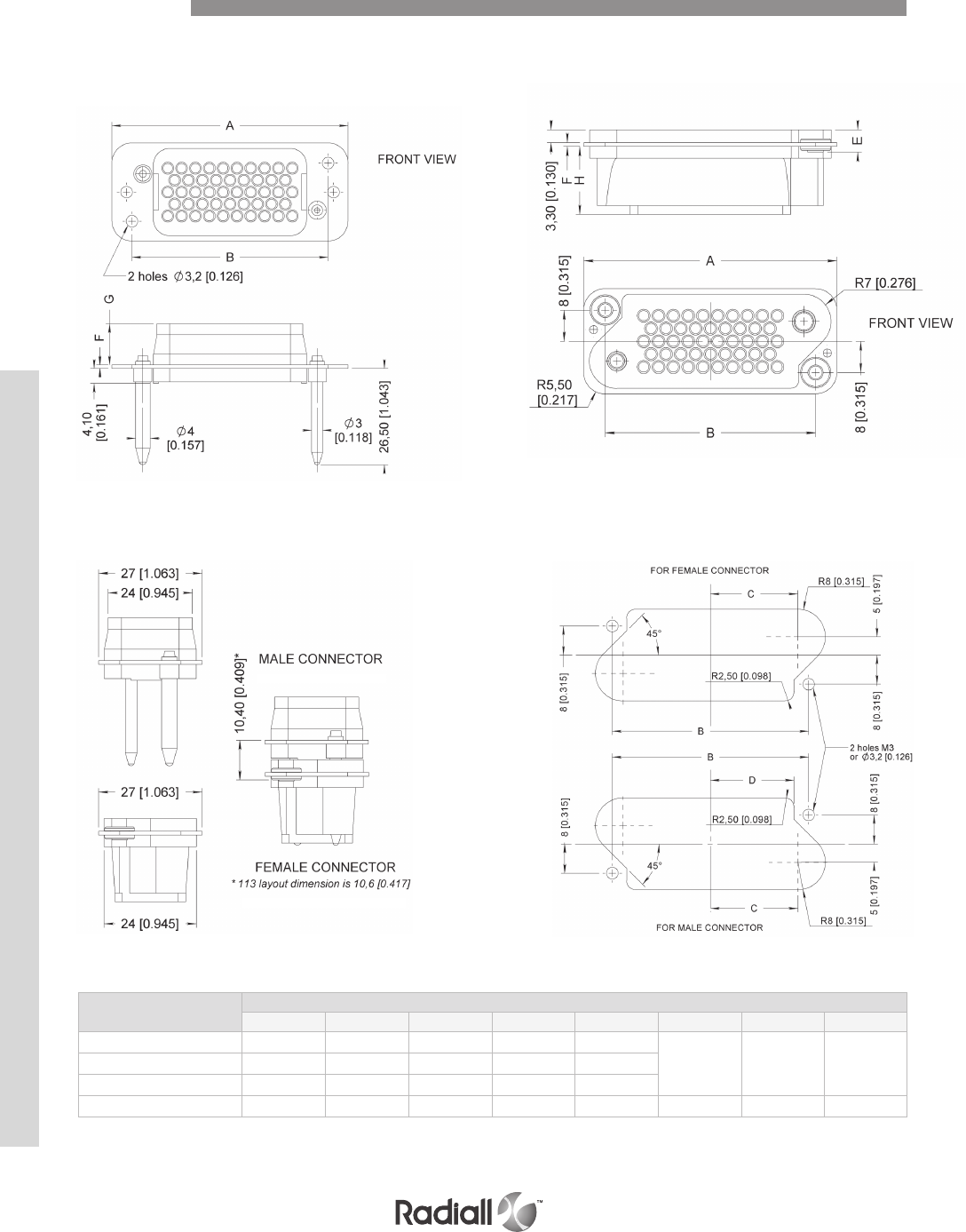
MCS-R SERIES
SINGLE SHELL DIMENSIONS mm (inch)
Mated Shell Dimensions Panel Cut Outs
Plug
Plug
Receptacle
Receptacle
Contact
Arrangement
Plug & receptacle connector dimensions mm(inch)
A B C D E F G H
028 48.5 (1.909) 37.5 (1.476) 15.75 (0.620) 15.5 (0.610) 5.3 (0.209)
1 (0.039) 11.5 (0.452) 17.7 (0.697)
048 65 (2.559) 54 (2.126) 24 (0.945) 23.5 (0.925) 5.3 (0.209)
083 92.5 (3.642) 81.5 (3.209) 37.75 (1.486) 37.5 (1.476) 5.3 (0.209)
113 114.5 (4.508) 103.5 (4.075) 48.75 (1.919) 48.5 (1.909) 5.5 (0.217) 1.2 (0.047) 11.3 (0.445) 17.5 (0.689)
Dimensions
8-18
Our Most Important Connection is with You.™
Go online for data sheets & assembly instructions Visit www.radiall.com and enter the part number
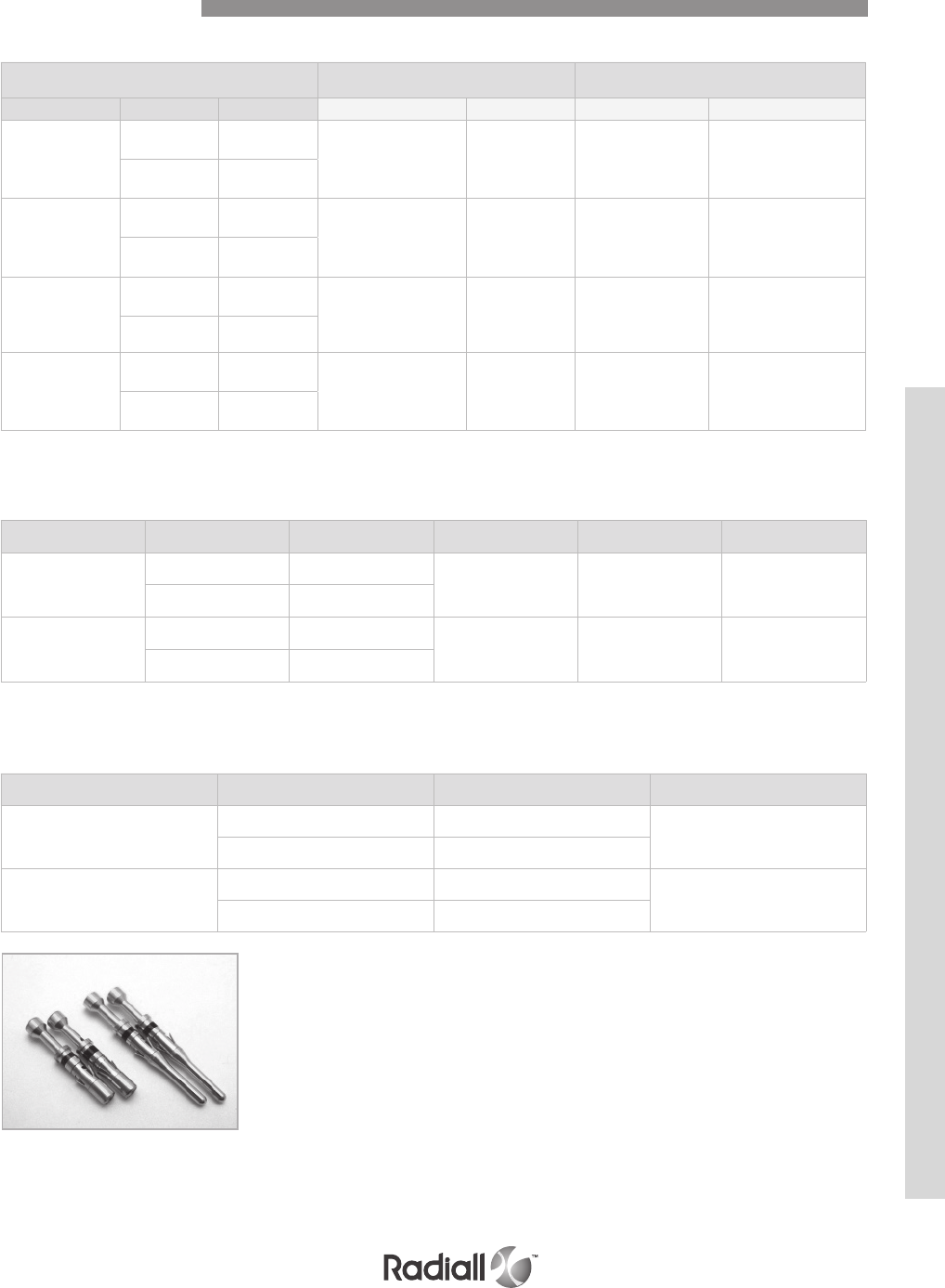
MCS-R SERIES
MICRO COAXIAL CONTACTS
Outer conductor
Description
Center conductor
Description
Cable type Type Part number Crimping tool Setting Crimping Tool Positionner
RG178
RG196 KX21
Pin 614120 282281
M22520/2-01 1282292
M22520/4-01
282973
M22520/4-02
Socket 690020
RG174
RG188
RG316
KX3 – KX22
Pin 614140 282281
M22520/2-01 2282292
M22520/4-01
282973
M22520/4-02
Socket 690040
AWG26
Twisted pair cable
Ø1.1
Pin 614160 282281
M22520/2-01 2282292
M22520/4-01
282973
M22520/4-02
Socket 690060
AWG24
Twisted pair cable
Ø1.3
Pin 614170 282281
M22520/2-01 2282292
M22520/4-01
282973
M22520/4-02
Socket 690070
CRIMP WIRE CONTACTS (2)
Cable type Type Part number Crimping tool Positioner Extraction tool
AWG16
AWG18
AWG20
Pin 614200 282291
M22520/1-01 282975 282920
Socket 690300
AWG20
AWG22
AWG24
Pin 614200 282291
M22520/1-01 282976 282920
Socket 690300
NOTES:
(1) For other termination please consult us
(2) Stripping length for cable types AWG16-18-20 is 6 and for types AWG20-22-24 it is 5
SOLDER WIRE CONTACTS (2)
Cable type Type Part number Extraction tool
AWG16
AWG18
AWG20
Pin 614230
282920
Socket 614330
AWG20
AWG22
AWG24
Pin 614240
282920
Socket 614340
Contact References (1)
8-19
Our Most Important Connection is with You.™
Go online for data sheets & assembly instructions Visit www.radiall.com and enter the part number
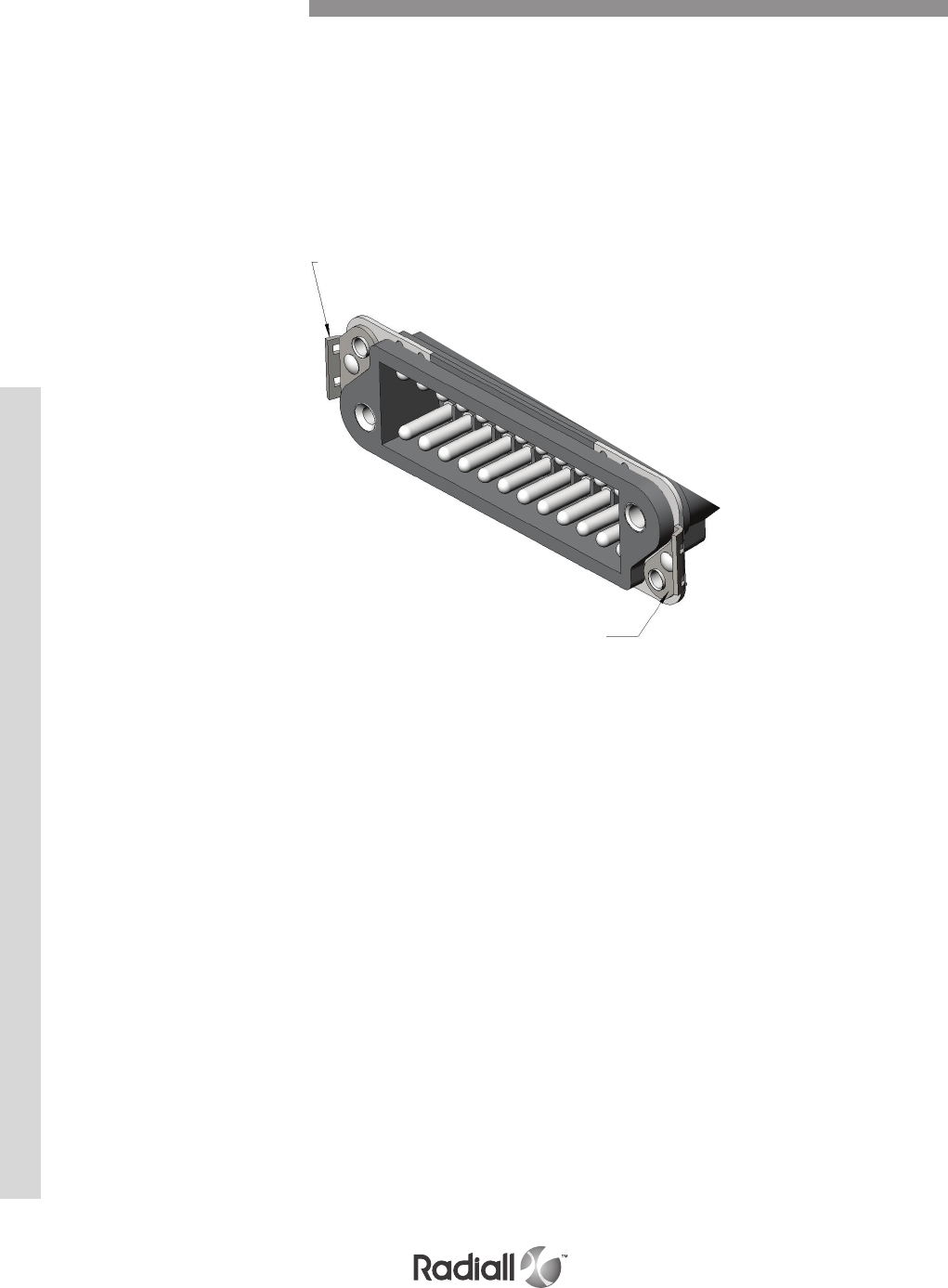
MCS-R SERIES
The brackets can only be used on the receptacle connector and enables it to
be fastened securely when its mating half is fitted with a hood
The brackets replace the floating eyelets on the receptacle connector
On both series B and MCSR when VP code is ordered, the corresponding
hood must be ordered with the male connector
Locking System Code VP
VP code
VP code
8-20
Our Most Important Connection is with You.™
Go online for data sheets & assembly instructions Visit www.radiall.com and enter the part number
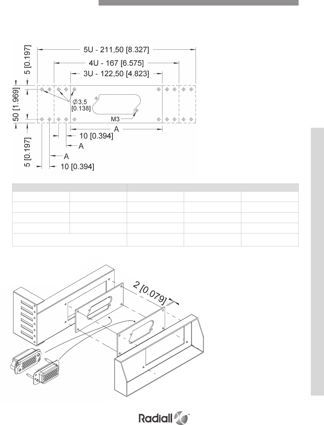
MCS-R SERIES
The mounting plates already blanked out, simplify the wall cut out on the rack or panel as well as on any
other item designed to support the connector. The latter is directly fitted to the mounting plate, which can
then be easily secured with accuracy on the equipment due to the four oblong holes of the mounting plate.
Series Reference following number of cut outs
B MCSR 3 U 4 U 5 U
14 48 PP314 PP414 PP514
24 83 PP324 PP424 PP524
32 113 - PP432 -
Dimensions A
mm (inch)
114.5
(4.508)
139
(5.472)
183.5
(7.224)
Thickness
Rack
Panel
Connectors Mounting Plates
8-21
Our Most Important Connection is with You.™
Go online for data sheets & assembly instructions Visit www.radiall.com and enter the part number
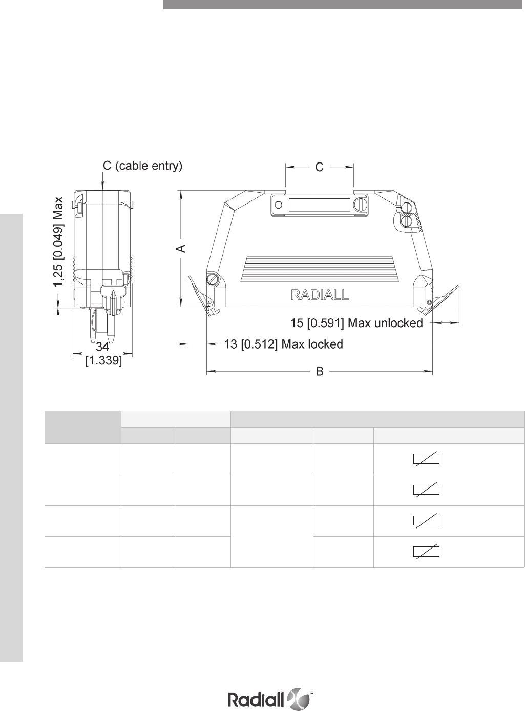
MCS-R SERIES
The backshells for both series B and MCSR are available in four sizes and are supplied
in two halves which enables them to be fitted after the wiring of the connectors.
They are available either with TOP or SIDE (45°) cable entry.
Each backshell is fitted with a pair of locking clips, one fixed on each end. This allows the connector
backshell assembly to be fastened securely to the mating connector fitted with the VP brackets.
TOP ENTRY
Part number for
TOP ENTRY
Number of contacts B & MCSR dimensions mm (inch)
B series MCSR series A B C
612813 8 28
52.5
(2.067)
60.5
(2.382) 26 x 10
(1.024 x 0.394)
612823 14 48 77
(3.031) 26 x 15
(1.024 x 0.591)
612837 24 83
65.5
(2.579)
104.5
(4.114) 38 x 20
(1.496 x 0.787)
612845 32 113 126.5
(4.980) 38 x 20
(1.496 x 0.787)
(1)
NOTE:
(1) This screw is for grounding purpose.
Connectors Accessories
8-22
Our Most Important Connection is with You.™
Go online for data sheets & assembly instructions Visit www.radiall.com and enter the part number

MCS-R SERIES
Part
number for
SIDE ENTRY
Number of contacts B & MCSR dimensions mm (inch)
B series MCSR series A B C
612814 8 28
63
(2.480)
60.5
(2.382) 26 x 10
(1.024 x 0.394)
612824 14 48 77
(3.031) 26 x 15
(1.024 x 0.591)
612838 24 83
73
(2.874)
104.5
(4.114) 38 x 20
(1.496 x 0.787)
612846 32 113 126.5
(4.980) 38 x 20
(1.496 x 0.787)
Connectors Accessories
SIDE ENTRY
8-23
Our Most Important Connection is with You.™
Go online for data sheets & assembly instructions Visit www.radiall.com and enter the part number
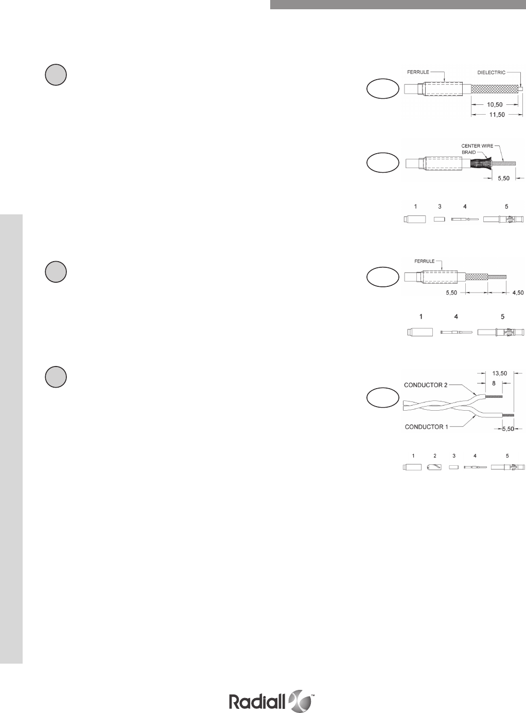
MCS-R SERIES
Three different modes of assembly are to be considered depending on the cable type used. The two first
assemblies A and B are applicable for braid coaxial cables, whilst the third assembly C is applicable for
twin conductor cable. The three mounting procedures are identical for both contact types, pin and socket.
NOTES:
(1) Insulating bush
(2) Socket or pin contact
(3) Contact body
After sliding the ferrule over the cable, strip the
latter to dimensions shown in B (mounting of
coaxial contacts without insulator bushing).
- Comb the braid and place the center contact over
the conductor butting it against the dielectric.
- Place the sub assembly into tool 282281
and crimp the center contact.
- The following steps are identical to those indicated in A.
BB
Micro coaxial contacts with twin conductor cable
After sliding the ferrule over the twin conductors
and stripping them to dimensions shown in C.
Note: conductor 1 is for the centre contact,
whilst conductor 2 is for earthing.
- Slide the adaptor 2 and the insulator bushing (1) over
conductor 1.
- Place the center contact (2) over the conductor,
butting it against the sheath.
- Place the sub assembly into tool 282281
and crimp the centre contact.
- Slide the cable and contact into the
body (3), ensuring that its home.
- Slide the adaptor 2 onto the body (3) against the shoulder.
- Place conductor 2 into the helical slot.
- Slide the ferrule over the adaptor and conductor
2, up to the shoulder of the body (3).
- Place the assembly into tool 282292 and crimp the ferrule.
C
C
Mounting procedure coaxial cables
After sliding the ferrule over the cable and stripping
the latter to the dimensions shown in A1.
- Comb the braid in opening it up, strip the
center wire to the dimension shown in A2.
- Slide the insulator bushing (1) over the dielectric .
- Place the center contact (2) over the conductor, the
contact must butt against the insulator bushing (1).
- Crimp the center contact with tool 282281.
- Slide the cable and contact into the body(3)
ensuring that it’s pushed home, then trim
back the braid over the body (3).
- Slide the ferrule over the braid up to the body shoulder.
- Place the assembly into tool 282292
and crimp the ferrule.
AA1
A2
Micro Coaxial Contacts Assembly Instructions
8-24
Our Most Important Connection is with You.™
Go online for data sheets & assembly instructions Visit www.radiall.com and enter the part number
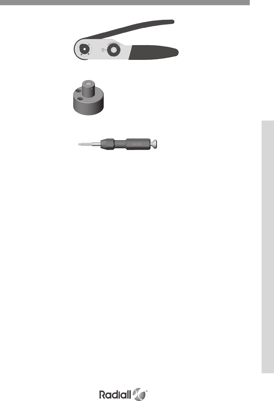
MCS-R SERIES
CRIMP TOOLS
POSITIONERS
EXTRACTION TOOL
282281 – M22520/2-01
282291 – M22520/1-01
282292 – M22520/4-01
282973 – M22520/4-02
282976 – Daniels TP616
282975 – Daniels TP617
282920
Tools
8-25
Our Most Important Connection is with You.™
Go online for data sheets & assembly instructions Visit www.radiall.com and enter the part number

MCS-R SERIES
Notes
8-26
Our Most Important Connection is with You.™
Go online for data sheets & assembly instructions Visit www.radiall.com and enter the part number
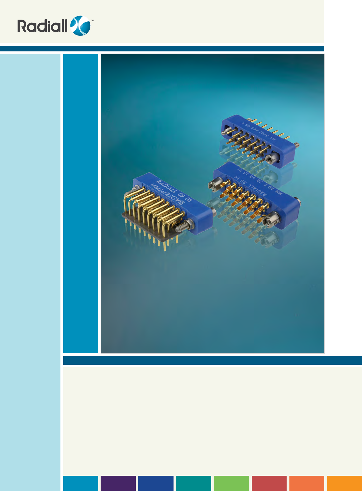
SECTION 9
MM & MB Series

Our Most Important Connection is with You.™

Section 9 table of contentS
9-3
Our Most Important Connection is with You.™
Go online for data sheets & assembly instructions Visit www.radiall.com and enter the part number
Introduction of MM and MB series ........................................................................................................................... 9-4
Features .................................................................................................................................................................... 9-5
Applications ............................................................................................................................................................... 9-5
Product overview of mm series .......................................................................................................................... 9-6
Technical characteristics ......................................................................................................................................... 9-7
How to order connectors .......................................................................................................................................... 9-8
Contact arrangements .............................................................................................................................................. 9-9
Termination style .................................................................................................................................................... 9-10
Printed circuit drill pattern ......................................................................................................................... 9-11 & 9-12
Guides and jackscrews ........................................................................................................................................... 9-13
Panel cut-out ........................................................................................................................................................... 9-14
Connector mating compatibility ............................................................................................................................. 9-15
Backshell type availability ...................................................................................................................................... 9-15
Top entry backshells ............................................................................................................................................... 9-16
Product overview of mB series ........................................................................................................................ 9-18
Technical characteristics ....................................................................................................................................... 9-19
How to order connectors ........................................................................................................................................ 9-20
Contact arrangements ............................................................................................................................................ 9-21
Termination style .................................................................................................................................................... 9-22
Panel cut-out ........................................................................................................................................................... 9-23
Printed circuit drill pattern ....................................................................................................................... 9-24 to 9-27
Guides and jackscrews ............................................................................................................................................. 9-28
Connector mating compatibility ............................................................................................................................. 9-29
Backshell type availability ...................................................................................................................................... 9-30
Top entry backshells ............................................................................................................................................... 9-31
Side entry backshells .............................................................................................................................................. 9-32
Accessories ............................................................................................................................................................. 9-33
Contents

9-4
Our Most Important Connection is with You.™
Go online for data sheets & assembly instructions Visit www.radiall.com and enter the part number
The Radiall miniature and submaniature rectangular multicontact connectors meet the requirements
of the standard MIL-C-28748 performance requirements. They are rugged connectors and offer high
performance for high contact density.
The connectors in each series consist of an insulator with male and female contacts which include
several pin sizes.
Each connector features a male guide at one end and a female guide at the other. This arrangement
ensures polarization of the connector when coupled. These guides can be smooth (rack guides) or screw
closing (fixed or rotating jackscrews).
The contacts male or female are made of copper base alloy plated gold over nickel. The female contacts
have 4 slots which ensures perfect mating, constant contact pressure and excellent mechanical and
electrical performance. The contacts have a slight amount of float in order to allow self alignment
during mating. Each series includes a different termination type; solder pot, straight or right angle
solder pin for PCB, and wrapping.
The MM series
This series consists of six sizes of connectors with contact arrangements for 7, 14, 20, 26, 34 and 50 size
22 contacts
Ø 0.76mm / 0.030inch.
The series offers four types of terminations:
- Solder pot for wire (AWG22 max)
- Straight solder pin for PBC
- Right angle solder pin for PBC
- Wire wrap
These connectors are fitted with rack guides or fixed or rotating jackscrews at each end. A protective
covering for wire terminations can be installed on the connector.
The MB series
This series consists of twelve sizes of connectors with contact arrangements for 2, 3, 5, 11, 14, 20, 25,
34, 42, 50 and 75 size 20 contacts Ø 1mm / 0.039inch.
The series offers three types of terminations:
- Solder pot for wire (AWG20 max)
- Straight solder pin for PBC
- Right angle solder pin for PBC
These connectors are fitted with rack guides or fixed or rotating jackscrews at each end.
Wires and soldered terminations for wire can be protected by either top or side entry backshells or by
potting covers for 2 to 14 contacts connectors.
A range of top and side entry backshells with cable clamps in yellow anodized aluminium alloy are
available. They are designed to protect the soldered wire connections, provide strain relief to the cable
and facilitate the disengagement of the mated connectors.
Fitted with threaded posts they are suitable for connectors fitted with rack guides or fixed jackscrews.
When fitted with rotating jackscrew guides they are fixed to the connectors without guides and
jackscrews.
For the MB series there are also thermoplastic covers for “potting” ensuring that the terminated wires
at the back of the insulator are protected.
Introduction
Features
MM & MB SERIES

9-5
Our Most Important Connection is with You.™
Go online for data sheets & assembly instructions Visit www.radiall.com and enter the part number
Their mass and volume make them particularly suitable for the following applications: civil and military,
in-flight equipment, instrumentation, missile, etc.
Originally developed for rack and panel assemblies they can be adapted for cable to cable applications
with cable clamp backshell.
© Dassault Aviation - K. Tokunaga
Applications
MM & MB SERIES
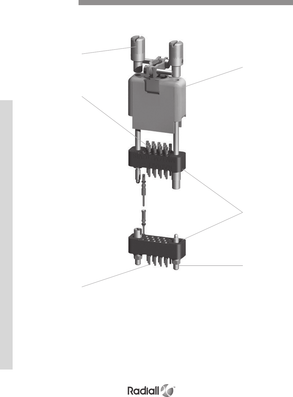
MM SERIES
9-6
Our Most Important Connection is with You.™
Go online for data sheets & assembly instructions Visit www.radiall.com and enter the part number
Detailed view of the various parts of the MM series connector.
Rotating jackscrew
Backshell
Male or
female
insulator
Fixed
jackscrew
Solder pot pin
contacts
Socket
contact
for PCB
Product Overview
9-7
Our Most Important Connection is with You.™
Go online for data sheets & assembly instructions Visit www.radiall.com and enter the part number
Conforms to MIL-C-28748 performance requirements and UTE-C-93426 HE611 standard.
- Current rating: 5A
- Test voltage @ sea level: 1000 Vrms / 50 Hz
- Operating voltage @ sea level: 350 Vrms / 50 Hz
- Operating voltage @ 70,000 feet: 90 Vrms / 50 Hz
- Insulation resistance: > 5000 MΩ
- Contact resistance: < 5 mΩ
MECHANICAL & ENVIRONMENTAL
Description Material Finish
Insulator glass filled diallylphthalate
conform to MIL-M-14SDG-F
/
Pin contact copper alloy gold over nickel
Socket contact copper alloy gold over nickel
Guides & jackscrews stainless steel /
Backshells aluminium alloy yellow anodized
MATERIALS
MASSES g (oz)
Weight of connectors mated
Contact arrangement 07 14 20 26 34 50
Without guides 2.8 (0.99) 5 (0.18) 6.6 (0.23) 8.1 (0.29) 12.1 (0.43) 15 (0.53)
With guides or jackscrew 4.7 (0.17) 7 (0.25) 8.4 (0.30) 10 (0.35) 13 (0.46) 17.1 (0.60)
With backshells and guides
or jackscrews 12 (0.42) 15.5 (0.55) 17 (0.60) 19.4 (0.68) 23.2 (0.81) 32.8 (1.16)
Technical Characteristics
ELECTRICAL
Conforms to MIL-C-28748 performance requirements and UTE-C-93426 HE611 standard.
- Temperature range: - 55°C (-131°F) to 125°C (257°F)
- Durability: 500 mating cycles
- Shock: 100g / 6ms
- Vibration: 20g / 10-2000 Hz
- Humidity: 56 days
- Contact insertion force: 3N
- Salt spray: 48 hours
MM SERIES
MM SERIES
9-8
Our Most Important Connection is with You.™
Go online for data sheets & assembly instructions Visit www.radiall.com and enter the part number
MM 34 M 20 VL IS
Series
MM series
Contact arrangement (refer to page 9-9)
07 - 14 - 20 - 26: 34: 50
Contact type
M: pin
F: socket
Termination style (refer to page 9-10)
20: solder pot
21: straight solder pin for PBC
22: right angle solder pin for PBC
23: wraping contact 1 wrap
24: wraping contact 2 wrap
25: wraping contact 3 wrap
Guides and jackscrews (refer to page 9-13)
00: without guides and jackscrews (1)
G3: rack guides (2)
GV: fixed jackscrews (2)
VR: short rotating jackscrews
VL: long rotating jackscrews (3)
Thread, guides or jackscrews
00: without guides and jackscrews
IS: ISO (M2 x 0.4)
NC: 2-56 UNC
NOTES:
(1) Connectors to be used with backshell HC (see page 9-15) and rotating jackscrews
(2) Connectors to be used with backshell HA (see page 9-15)
(3) VL jackscrew assembly is not available for termination style type 22
The part number is printed on the insulator side
How to Order Connectors
Connector Identification
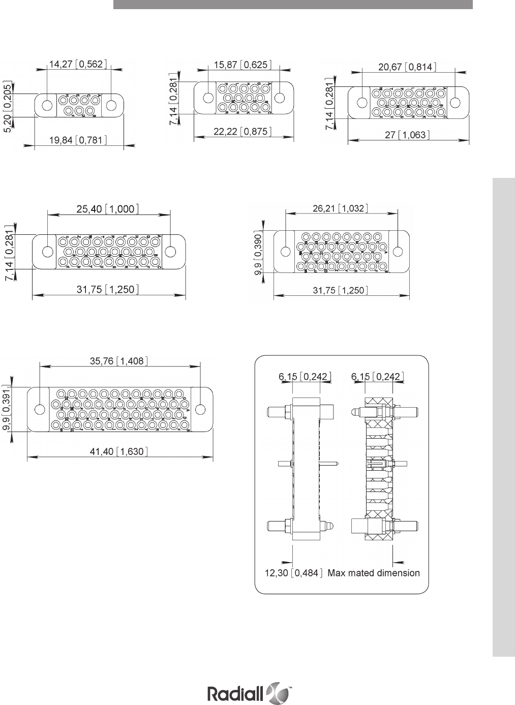
9-9
Our Most Important Connection is with You.™
Go online for data sheets & assembly instructions Visit www.radiall.com and enter the part number
MALE CONNECTOR wiring side dimensions mm (inch)
50
26 34
07 2014
Mating dimensions
Contact Arrangements
MM SERIES
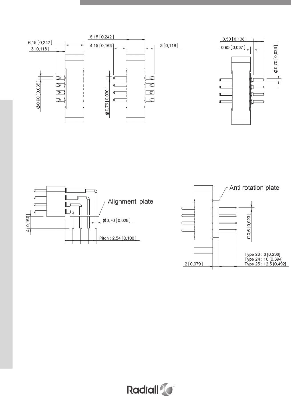
MM SERIES
9-10
Our Most Important Connection is with You.™
Go online for data sheets & assembly instructions Visit www.radiall.com and enter the part number
TYPE 20
Solder pot
TYPE 22
Right angle solder pin for PCB
TYPE 21 (1)
Straight solder pin
for PCB
TYPE 23 - 24 - 25
23: wire wrap termination (1 level)
24: wire wrap termination (2 level)
25: wire wrap termination (3 level)
NOTE:
(1) For termination style type 21, the connectors are supplied with insulating washers in order to make space between the insulator and the PCB
Dimensions mm (inch)
Termination Styles
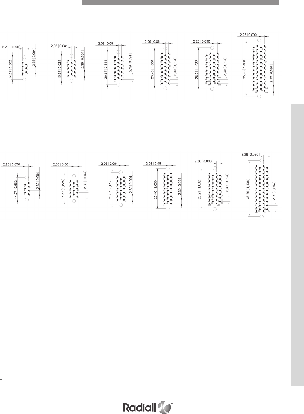
9-11
Our Most Important Connection is with You.™
Go online for data sheets & assembly instructions Visit www.radiall.com and enter the part number
TYPE 21 Termination style - Connector with socket contacts
TYPE 21 Termination style - Connector with pin contacts
07
07
14
14
20
20
26
26
34
34
50
50
PCB component side view
Printed Circuit Drill Pattern
PCB component side view
NOTES:
• Printed circuit drilling 0.8 mm ±0.05 (0.031 ±0.002)
• Drilling to fix the connector. Required for guides G3 and GV fixing only
2.2mm (0.087) for ISO guides and 2.4mm (0.094) for UNC guides
MM SERIES
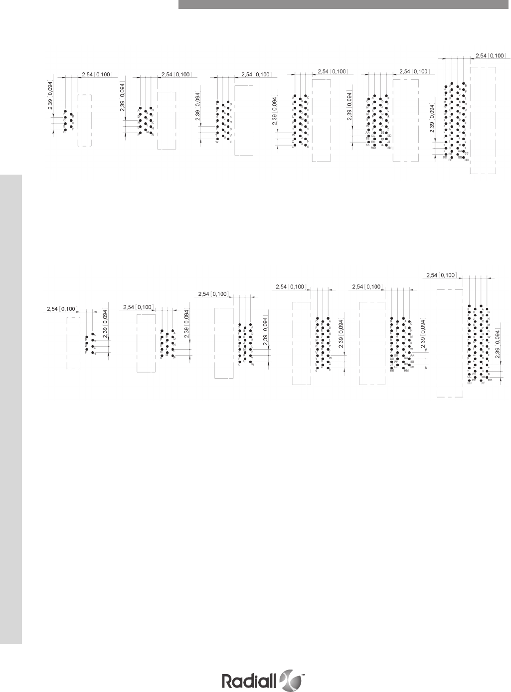
MM SERIES
9-12
Our Most Important Connection is with You.™
Go online for data sheets & assembly instructions Visit www.radiall.com and enter the part number
TYPE 22 Termination style - Connector with socket contacts
NOTE:
• Printed circuit drilling 0.8 mm ±0.05 (0.031 ±0.002)
07 14 20 26 34 50
TYPE 22 Termination style - Connector with pin contacts
07 14 20 26 34 50
Printed Circuit Drill Pattern
PCB component side view
PCB component side view
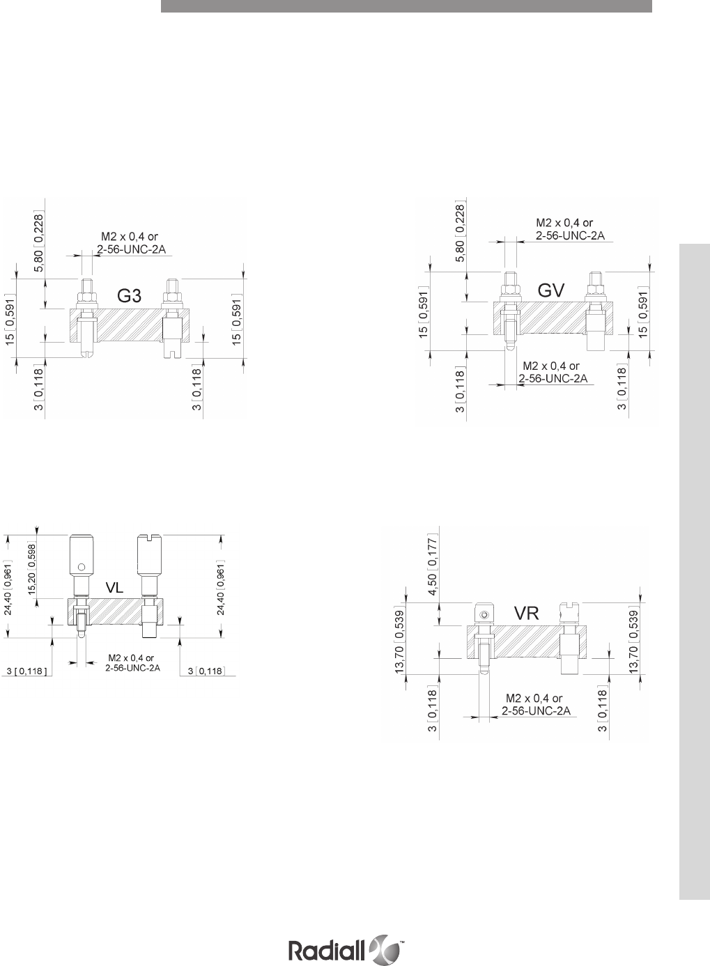
9-13
Our Most Important Connection is with You.™
Go online for data sheets & assembly instructions Visit www.radiall.com and enter the part number
Stainless steel guides and jackscrews are supplied with either ISO (M2 x 0.4) or UNC (2-56 UNC)
threads. The guides or jackscrews types (G3 – GV – VL – VR) and the type of thread (ISO or UNC)
required are to be defined in the part number on page 9-8.
The standard configuration of guides and jackscrews is:
- Male guide (or jackscrew) at the end nearest contact A of the female connector.
- Female guide (or jackscrew) at the end nearest contact A of the male connector.
These guide and jackscrews can be used with backshell HA
Mating torque: 0.2N.m
Not available for termination style type 22
Cannot be used with any backshell Mating torque: 0.2N.m
Cannot be used with any backshell
RACK GUIDES TYPE G3
LONG AND SHORT ROTATING JACKSCREWS TYPE VL – VR
FIXED JACKSCREWS TYPE GV
Guides and Jackscrews
MM SERIES
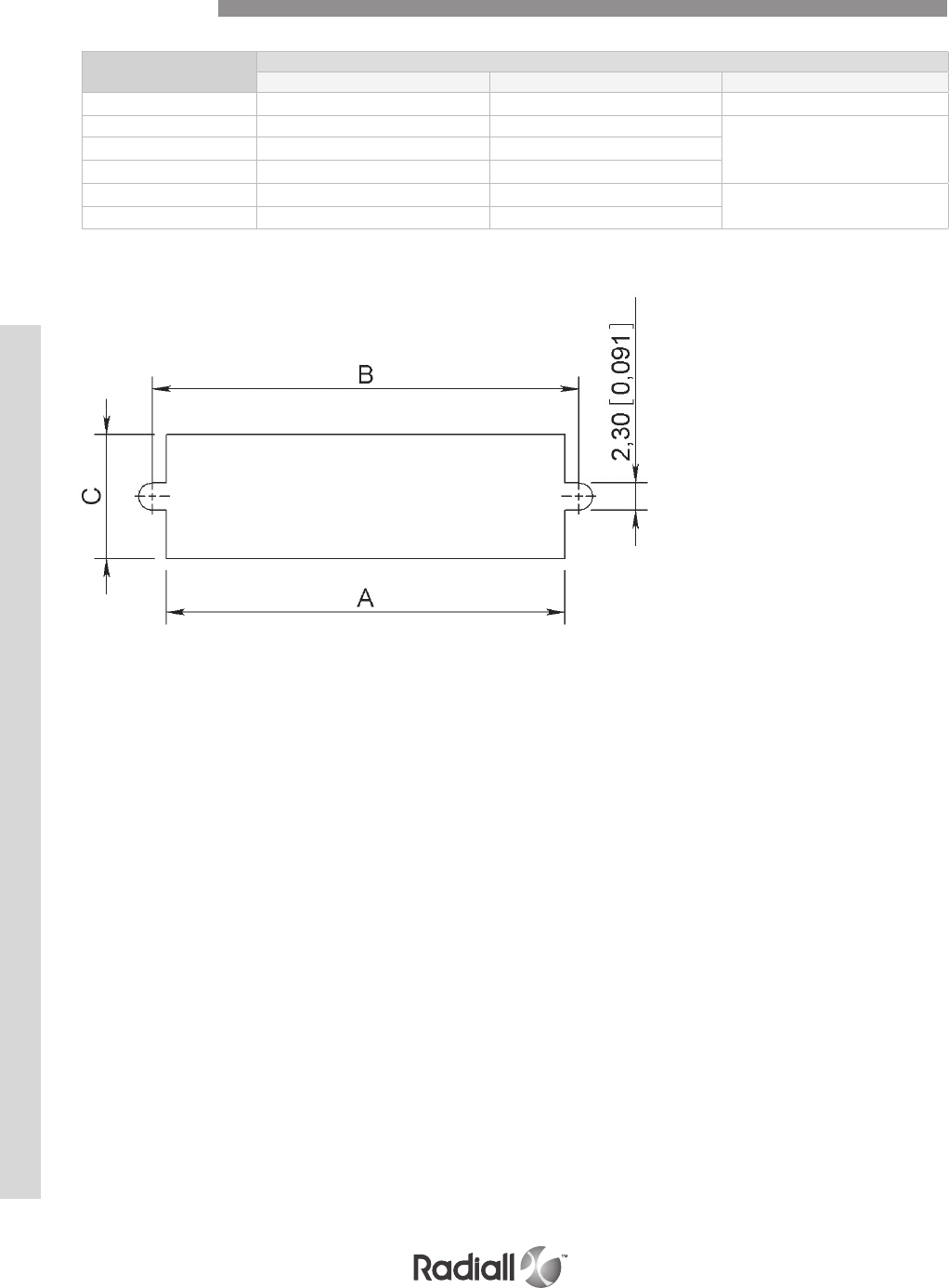
MM SERIES
9-14
Our Most Important Connection is with You.™
Go online for data sheets & assembly instructions Visit www.radiall.com and enter the part number
Contact
Arrangement
Dimensions mm (inch)
A B C
07 11.9 (0.468) 14.27 (0.562) 5.8 (0.228)
14 13.5 (0.531) 15.87 (0.625)
7.6 (0.299)
20 18.3 (0.720) 20.67 (0.814)
26 23 (0.905) 25.4 (1)
34 23.9 (0.940) 26.2 (1.031) 10.4 (0.409)
50 33.4 (1.315) 35.76 (1.408)
Panel Cut-Out
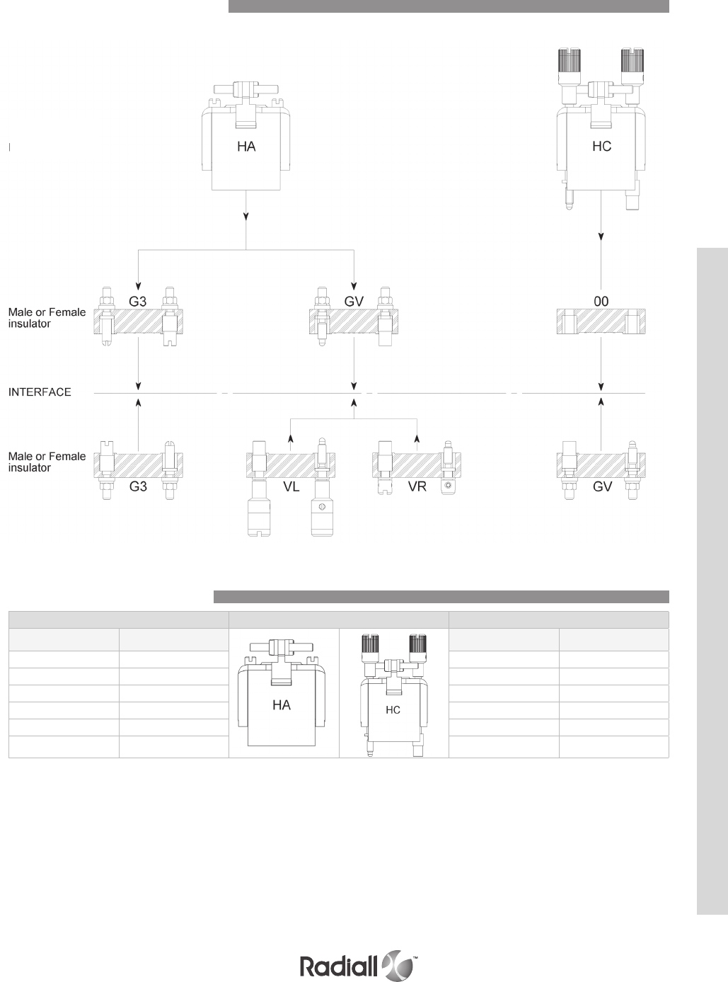
9-15
Our Most Important Connection is with You.™
Go online for data sheets & assembly instructions Visit www.radiall.com and enter the part number
Use with backshell – Termination style type 20 only
Use without backshell – All termination style type
Fixing of hoods only suitable for insulator with termination style type 20 (solder pot)
BACKSHELL TYPE
Thread Hood Thread
NC
(2-56 UNC)
ISO
(M2 x 0.4)
ISO
(M2 x 0.4)
NC
(2-56 UNC)
07 07 07 07
14 14 14 14
20 20 20 20
26 26 26 26
34 34 34 34
50 50 50 50
Connector Mating Compatibility
Backshell Type Compatibility
MM SERIES
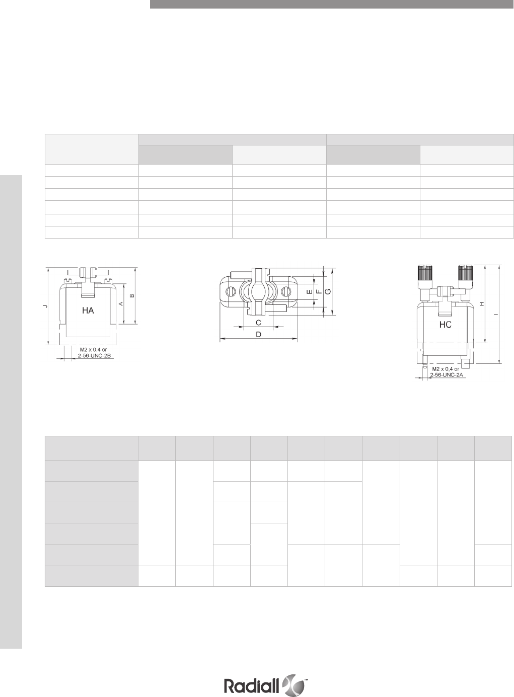
MM SERIES
9-16
Our Most Important Connection is with You.™
Go online for data sheets & assembly instructions Visit www.radiall.com and enter the part number
TYPE HA
Backshells supplied with two internal threaded posts which are screwed into the guides G3 or
jackscrews GV.
PART NUMBERS
Dimensions mm (inch)
Contact
Arrangement A B C D E F G H I J
07
15.9
(0,626)
23.15
(0.911)
5.5
(0.216)
19.8
(0.779)
4
(0.157) 6.8 (0.268)
13.5
(0.531) 31.9
(1.256)
38.2
(1.504)
29.4
(1.157)
14 10
(0.394)
22.2
(0.874)
6
(0.236) 8.8 (0.346)
20 14
(0.551)
27
(1.063)
26 31.8
(1.252)
34 19
(0.748) 9.5 (0.374) 11.8
(0.464)
15.7
(0.618)
30.4
(1.197)
50 30.5
(1.201)
38.5
(1.516)
29.7
(1.169)
41.4
(1.630)
46.6
(1.835)
52.9
(2.083)
44.8
(1.764)
Contacts
Arrangements
Type HA Type HC
With threads
M2 x 0.4
With threads
2-56 UNC
With screws
M2 x 0.4
With screws
2-56 UNC
07 MM07HAIS MM07HANC MM07HCIS MM07HCNC
14 MM14HAIS MM14HANC MM14HCIS MM14HCNC
20 MM20HAIS MM20HANC MM20HCIS MM20HCNC
26 MM26HAIS MM26HANC MM26HCIS MM26HCNC
34 MM34HAIS MM34HANC MM34HCIS MM34HCNC
50 MM50HAIS MM50HANC MM50HCIS MM50HCNC
NOTE:
Fixing of backshells only suitable for insulator with termination style type 20 (solder pot).
Mating torque: 0.15N.m
Top Entry Backshells
TYPE HC
Backshells supplied with two long rotating jackscrews. These backshells are mounted on connectors
without guides or jackscrews (code 00).

9-17
Our Most Important Connection is with You.™
Go online for data sheets & assembly instructions Visit www.radiall.com and enter the part number
Notes
MM SERIES
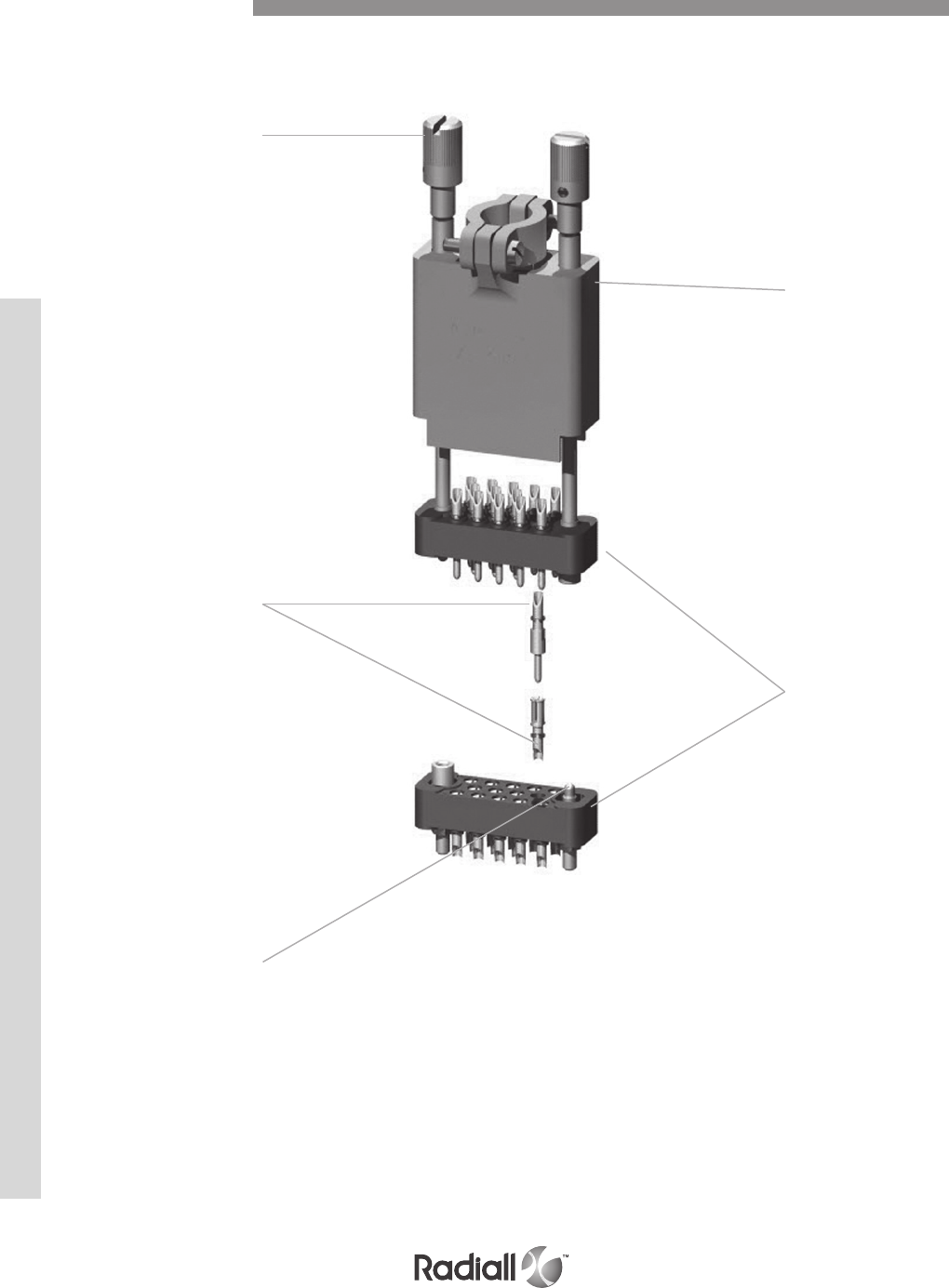
9-18
Our Most Important Connection is with You.™
Go online for data sheets & assembly instructions Visit www.radiall.com and enter the part number
Detailed view of the various parts of the MB series connector.
Rotating jackscrew
Backshell
Male or female
insultor
Solder pot
contacts
Fixed jackscrew
Product Overview
MB SERIES
9-19
Our Most Important Connection is with You.™
Go online for data sheets & assembly instructions Visit www.radiall.com and enter the part number
ELECTRICAL
Conforms to MIL-C-28748 performance requirements standard.
- Current rating: 7.5A
- Test voltage @ sea level: 1500 Vrms / 50 Hz
- Operating voltage @ sea level: 500 Vrms / 50 Hz
- Insulation resistance: > 5000 MΩ
- Contact resistance: < 5 mΩ
MECHANICAL & ENVIRONMENTAL
Description Material Finish
insulator glass filled diallylphthalate
conform to MIL-M-14SDG-F /
pin contact copper alloy gold over nickel
socket contact copper alloy gold over nickel
guides & jackscrews stainless steel /
backshells aluminium alloy yellow anodized
spring lever clamps stainless steel /
potting moulds nylon /
MATERIALS
MASSES g (oz)
Contact arrangement 02 03 05 07 11 14 20 26 34 42 50 75
Without guides 2.2
(0.07)
2.30
(0.81)
4
(0.14)
3.7
(0.13)
5.6
(0.20)
6.4
(0.23)
8.6
(0.30)
11
(0.39)
15.2
(0.54)
17.6
(0.62)
20.5
(0.72)
32.7
(1.15)
With rack guides 3.9
(0.14)
4
(0.14)
4.7
(0.17)
5.4
(0.19)
7.3
(0.26)
8.1
(0.29)
10.3
(0.36)
12.7
(0.45)
16.9
(0.60)
19.3
(0.68)
22.2
(0.78)
36.2
(1.28)
With backshells and jackscrew - - - 12.4
(0.44)
17.5
(0.62)
20.4
(0.72)
28
(0.99)
31.5
(1.11)
37.2
(1.31) -45.2
(1.59)
62
(2.19)
Technical Characteristics
Weight of connectors mated
- Temperature range: - 55°C (-131°F) to 125°C (257°F)
- Durability: 500 mating cycles
- Shock: 50g / 11ms
- Vibration: 20g / 10-2000 Hz
- Humidity: 21 days
- Contact insertion force: 3N
- Salt spray: 48 hours
MB SERIES
9-20
Our Most Important Connection is with You.™
Go online for data sheets & assembly instructions Visit www.radiall.com and enter the part number
MB 34 M 20 VL 00 IS
Series
MB series
Contact arrangement (refer to page 9-21)
02: 03 : 05 : 07 - 11 - 14
20: 26 : 34 : 42 - 50 - 75
Contact type
M: pin
F: socket
Termination style (refer to page 9-22)
85: solder pot
86: straight solder pin for PCB
87: right angle solder pin for PCB
Guides and jackscrews (refer to page 9-28)
00: without guides and jackscrews (1)
G1: rack guides (2)
GV: fixed jackscrews (2)
VR: short rotating jackscrews
VL: long rotating jackscrews (3)
Shipment without backshell and accessories
Thread, guides or jackscrews
00: without guides and jackscrews
IS: ISO (M2 x 0.4)
NC: 2-56 UNC
NOTES:
(1) Connectors to be used with backshell HC and HV (see page 9-29) or rack guides G1
(2) Connectors to be used with backshell HA and HL (see page 9-29
A spring clip locking system can be fitted (see page 9-33)
(3) VL jackscrews assembly is only available for termination style type 85
How to Order Connectors
MB SERIES
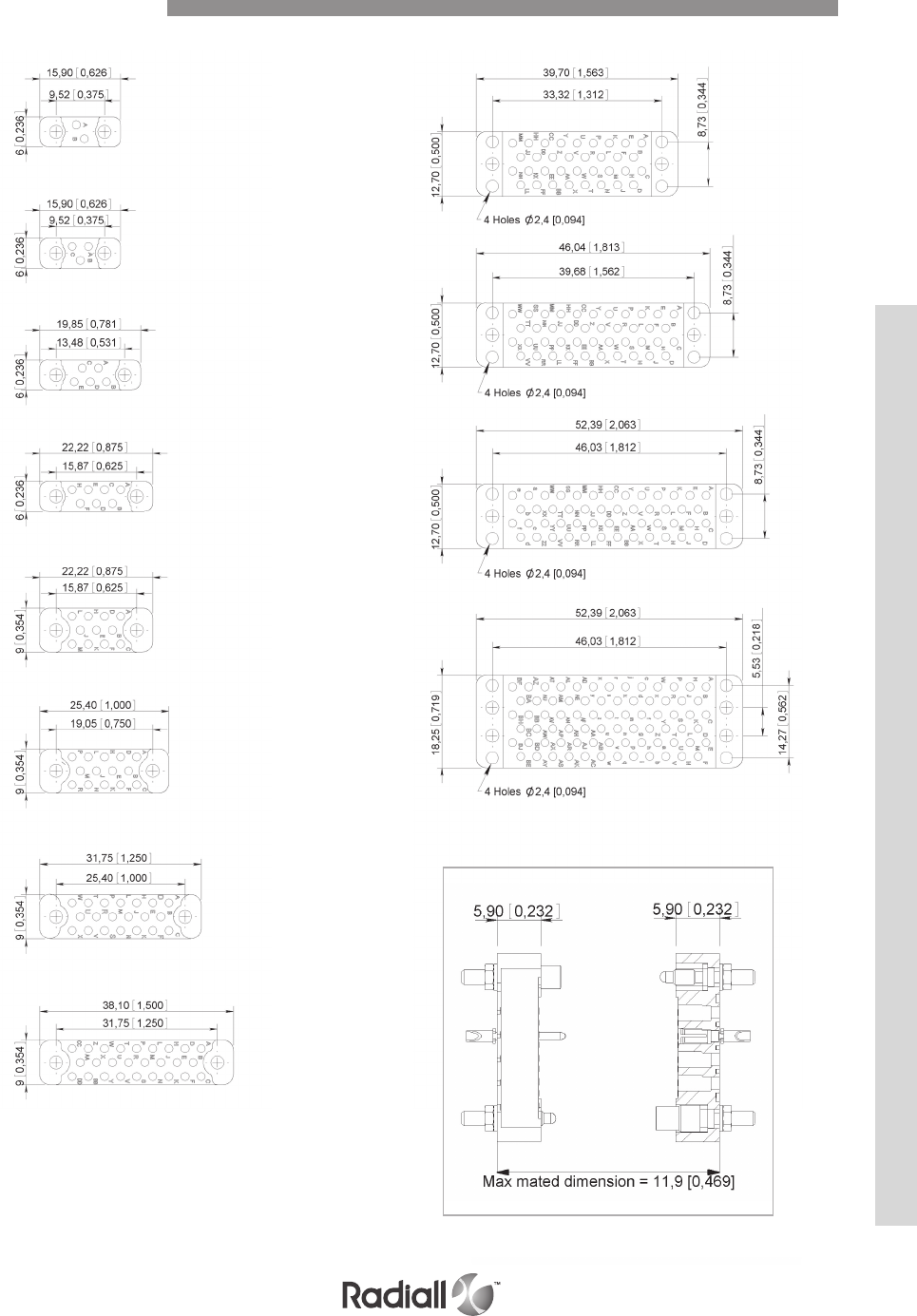
9-21
Our Most Important Connection is with You.™
Go online for data sheets & assembly instructions Visit www.radiall.com and enter the part number
02 34
42
50
75
03
05
07
11
14
20
26
Contact Arrangements
MATING DIMENSIONS
MB SERIES

9-22
Our Most Important Connection is with You.™
Go online for data sheets & assembly instructions Visit www.radiall.com and enter the part number
TYPE 85
Solder pot
TYPE 87
Right angle solder pin for PCB
All contacts arrangement and termination style have contacts stopped in rotation
(except contact arrangements 42, 50 and 75 for these please contact us).
TYPE 86 (1)
Straight solder pin for PCB
NOTE:
(1) The connectors are supplied with insulating washers wich act as spacers between the insulator and the PCB
DIMENSIONS mm (inch)
Termination Styles
MB SERIES
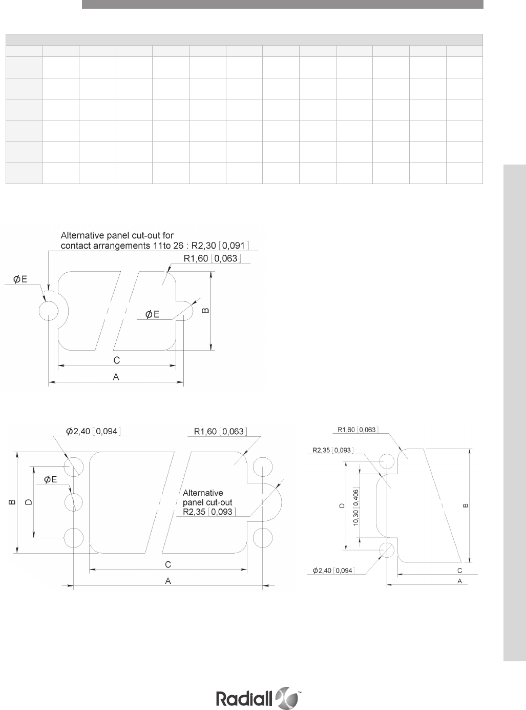
9-23
Our Most Important Connection is with You.™
Go online for data sheets & assembly instructions Visit www.radiall.com and enter the part number
Dimensions
02 03 05 07 11 14 20 26 34 42 50 75
A9.52
(0.375)
9.52
(0.375)
13.48
(0.531)
15.87
(0.625)
15.87
(0.625)
19.05
(0.750) 25.4 (1) 31.75
(1.250)
33.34
(1.313)
39.68
(1.562)
46.03
(1.812)
46.03
(1.812)
B6
(0.236)
6
(0.236)
6
(0.236)
6
(0.236)
9
(0.354)
9
(0.354)
9
(0.354)
9
(0.354)
12.5
(0.500)
12.5
(0.500)
12.5
(0.500)
18.28
(0.720)
C7.2
(0.283)
7.2
(0.283)
11
(0.433)
13.5
(0.531)
13.5
(0.531) 17 (0.669) 23.5
(0.925)
29.5
(1.161)
29.46
(1.160)
35.81
(1.410)
42.16
(1.660)
42.16
(1.660)
D--------8.73
(0.344)
8.73
(0.344)
8.73
(0.344)
14.27
(0.562)
ØE
(ISO)
2.2
(0.087)
2.2
(0.087)
2.2
(0.087)
2.2
(0.087)
2.2
(0.087)
2.2
(0.087)
2.2
(0.087)
2.2
(0.087)
2.2
(0.087)
2.2
(0.087)
2.2
(0.087)
2.2
(0.087)
ØE
(NC)
2.4
(0.094)
2.4
(0.094)
2.4
(0.094)
2.4
(0.094)
2.4
(0.094)
2.4
(0.094)
2.4
(0.094)
2.4
(0.094)
2.4
(0.094)
2.4
(0.094)
2.4
(0.094)
2.4
(0.094)
CONTACT ARRANGEMENTS 02 - 03 - 05 - 07 - 11 - 14 - 20 - 26
CONTACT ARRANGEMENTS 34 - 42 - 50 CONTACT ARRANGEMENT 75
dimensions mm (inch)
Panel Cut-Out
MB SERIES
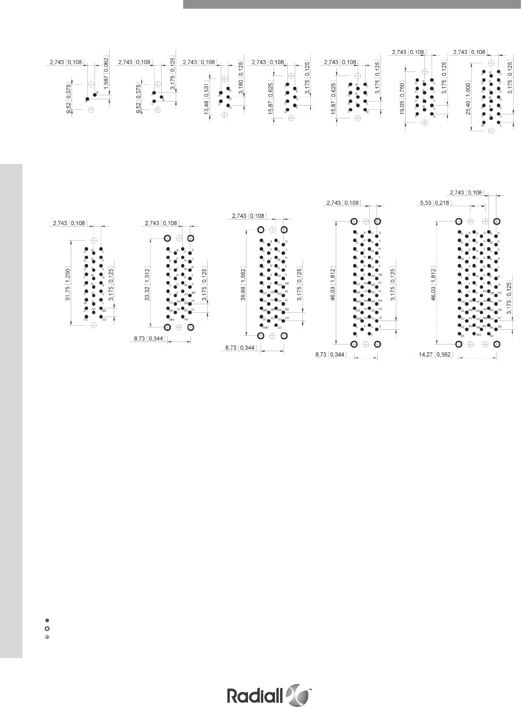
9-24
Our Most Important Connection is with You.™
Go online for data sheets & assembly instructions Visit www.radiall.com and enter the part number
TYPE 86 Termination style - connector with SOCKET contacts – PCB component side view in mm (inch)
02 03 05 07 11 14 20
7550423426
NOTES:
• Printed circuit drilling Ø 1.1 +0.1 (0.043 +0.003)
• Drilling to fix the connector Ø 2.4 (0.094)
• Drilling to fix the connector. Required for guides G1 and GV fixing only:
2.2 (0.087) Ø for ISO guides
2.4 (0.094) Ø for UNC guides
Printed Circuit Drill Pattern
MB SERIES

9-25
Our Most Important Connection is with You.™
Go online for data sheets & assembly instructions Visit www.radiall.com and enter the part number
TYPE 86 Termination style - connector with PIN contacts – PCB component side view in mm (inch)
02 03 05 07 11 14 20
7550423426
NOTES:
• Printed circuit drilling Ø 1.1 +0.1 (0.043 +0.003)
• Drilling to fix the connector Ø 2.4 (0.094)
• Drilling to fix the connector. Required for guides G1 and GV fixing only:
2.2 (0.087) Ø for ISO guides
2.4 (0.094) Ø for UNC guides
Printed Circuit Drill Pattern
MB SERIES

9-26
Our Most Important Connection is with You.™
Go online for data sheets & assembly instructions Visit www.radiall.com and enter the part number
TYPE 87 Termination style - connector with SOCKET contacts – PCB component side view in mm (inch)
02 03 05 07 11 14
5042342620
NOTE:
• Printed circuit drilling Ø 1.1 +0.1 (0.043 +0.003)
Printed Circuit Drill Pattern
MB SERIES
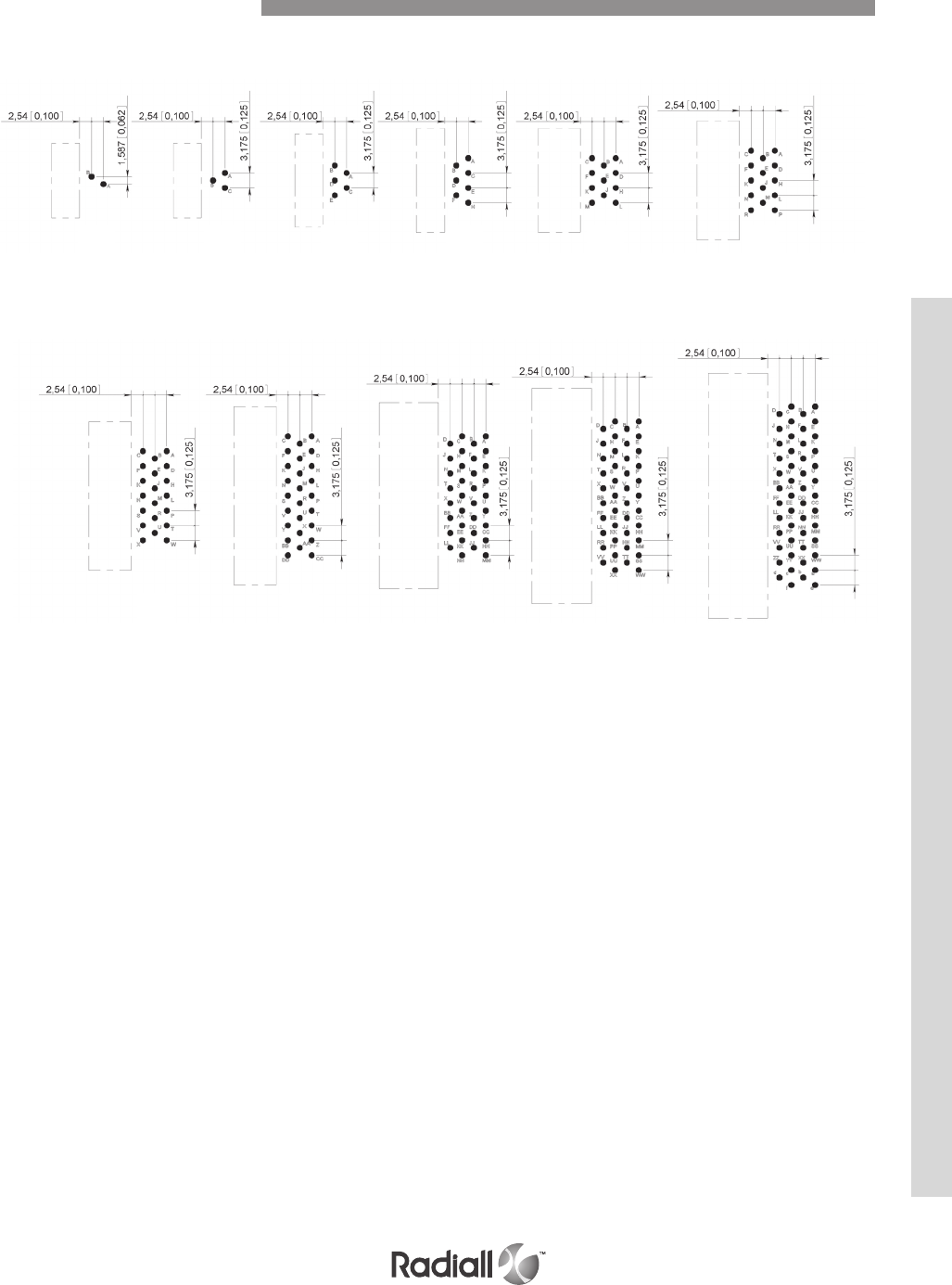
9-27
Our Most Important Connection is with You.™
Go online for data sheets & assembly instructions Visit www.radiall.com and enter the part number
TYPE 87 Termination style - connector with PIN contacts – PCB component side view in mm (inch)
02 03 05 07 11 14
34 42 502620
NOTE:
• Printed circuit drilling Ø 1.1 +0.1 (0.043 +0.003)
Printed Circuit Drill Pattern
MB SERIES
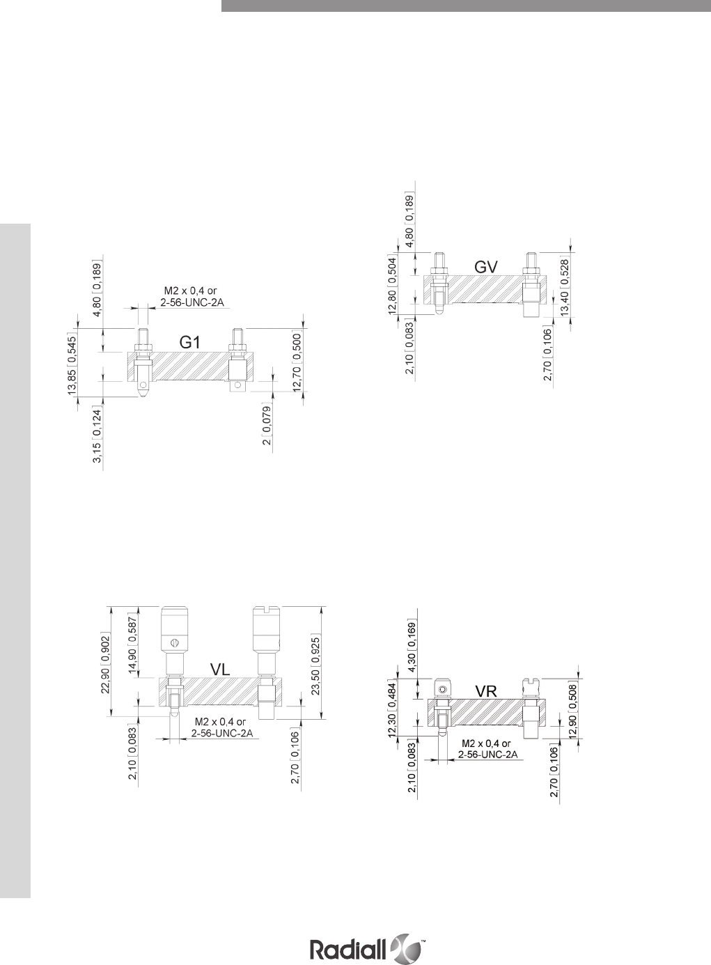
9-28
Our Most Important Connection is with You.™
Go online for data sheets & assembly instructions Visit www.radiall.com and enter the part number
Stainless steel guides and jackscrews are supplied with either ISO (M2 x 0.4) or UNC (2-56 UNC) threads.
The guides or jackscrews types G1 – GV – VL and VR and type of thread (ISO or UNC) required are to be
defined in the part number on page 9-20.
The standard configuration of guides and jackscrews is:
- Male guide (or jackscrew) at the end nearest contact A of the female connector.
- Female guide (or jackscrew) at the end nearest contact A of the male connector.
These guide and jackscrews can be used with backshells HA and HL
RACK GUIDES TYPE G1 FIXED JACKSCREWS TYPE GV
Mating torque: 0.2N.m
Not available for termination style type 87
Cannot be used with backshell
Mating torque: 0.2N.m
Cannot be used with backshell
LONG AND SHORT ROTATING JACKSCREWS TYPE VL – VR
The 2,3, 5 and 7 way GV jackscrews are held
securely in place by two flats on the
jackscrews whereas the jackscrews for
the other contact arrangements have
a square section to avoid rotation.
Guides and Jackscrews
MB SERIES
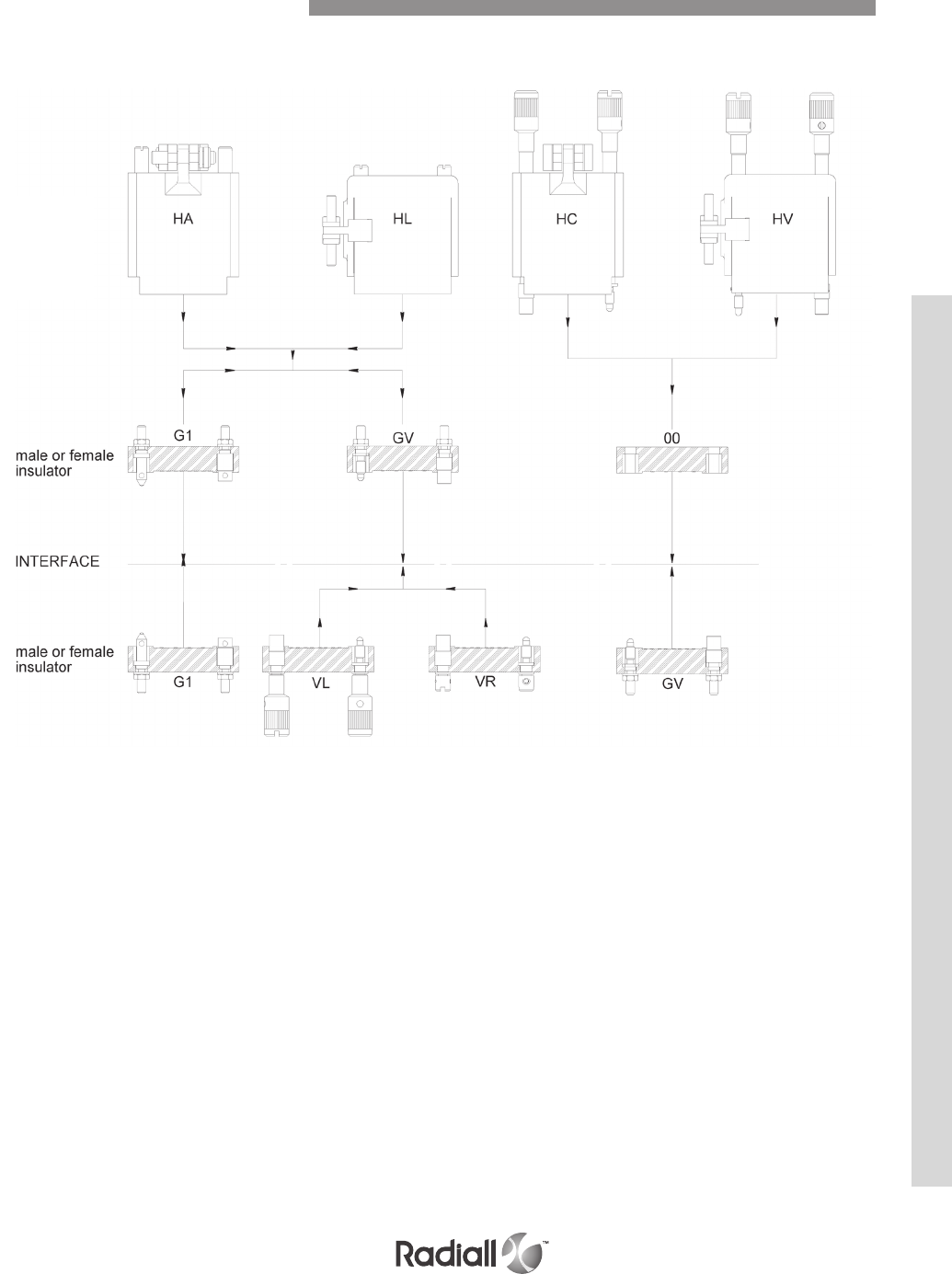
9-29
Our Most Important Connection is with You.™
Go online for data sheets & assembly instructions Visit www.radiall.com and enter the part number
Use with backshell – Termination style type 85 only
Use without backshell – All termination style type
Connector Mating Compatibility
MB SERIES

9-30
Our Most Important Connection is with You.™
Go online for data sheets & assembly instructions Visit www.radiall.com and enter the part number
Fixing of backshells only suitable for insulator with termination style type 85 (solder pot)
Thread Backshell Thread
NC
(2-56 UNC)
ISO
(M2 x 0.4)
ISO
(M2 x 0.4)
NC
(2-56 UNC)
07 07 - -
11 11 11 11
14 14 14 14
20 20 - -
26 26 26 26
34 34 34 34
50 50 50 50
75 75 - 75 (1)
07 07 - -
11 11 11 11
14 14 14 14
20 20 - -
26 26 26 26
34 34 34 34
50 50 50 50
75 75 - 75 (1)
NOTE:
(1) Available for male contact arrangement only
Backshell Type Availability
MB SERIES
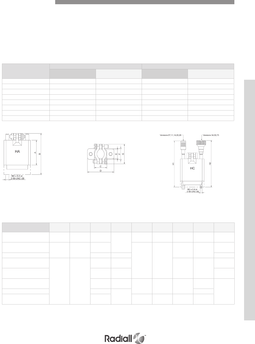
9-31
Our Most Important Connection is with You.™
Go online for data sheets & assembly instructions Visit www.radiall.com and enter the part number
TYPE HA
Backshells supplied with two internal threaded posts which are screwed into the guides G1 or
jackscrews GV.
PART NUMBERS
Contacts
Arrangements
Type HA Type HC
With threads
M2 x 0.4
With threads
2-56 UNC
With screws
M2 x 0.4
With screws
2-56 UNC
07 MB07HAIS2 MB07HANC MB07HCIS MB07HCNC
11 MB11HAIS2 MB11HANC MB11HCIS MB11HCNC
14 MB14HAIS2 MB14HANC MB14HCIS MB14HCNC
20 MB20HAIS2 MB20HANC MB20HCIS MB20HCNC
26 MB26HAIS2 MB26HANC MB26HCIS MB26HCNC
34 MB34HAIS2 MB34HANC MB34HCIS MB34HCNC
50 MB50HAIS2 MB50HANC MB50HCIS MB50HCNC
75 MB75HAIS2 MB75HANC MB75HCIS MB75HCNC
Mating torque:
0.15N.m
Dimensions mm (inch)
Contacts
arrangements (1) A B C D E F G H1 H2 (2)
07 9.52 (0.375) 22.9 (0.902) 9.13 (0.359)
22.2 (0.874)
5.95 (0.234) 7.5
(0.295)
13.5
(0.531)
30.62
(1.205) n/a
11 23.8
(0.937)
37.2
(1.465)
11.9
(0.468)
8.7
(0.342) 10.3 (0.405)
15.87
(0.625)
48.8
(1.921)
n/a
14 12.7 (0.500) 25.4 (1) n/a
20
30.16
(1.187) 48.4 (1.905)
18.26
(0.719)
31.7
(1.248) 23.8 (0.937) 55.2
(2.173)
n/a
26 23
(0.905) 38.1 (1.500) n/a
34 20.6
(0.811)
39.7
(1.563) 12.7 (0.500) 14.3 (0.563) 26.98
(1.062)
n/a
55.6 (2.189)50 22.2 (0.874)
52.4 (2.063)
n/a
75 23
(0.905)
18.2
(0.716)
19.8
(0.779)
34.52
(1.359) n/a
Top Entry Backshells
TYPE HC
Backshells supplied with two long rotating jackscrews. These backshells are mounted on connectors
without guides or jackscrews.
NOTES:
(1) Fixing of backshells only suitable for insulator with termination style type 85 (solder pot)
(2) Backshells 34, 50 and 75 are fitted with 4 screws to be fixed to the connector block
MB SERIES
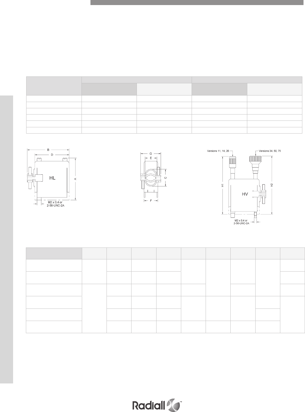
9-32
Our Most Important Connection is with You.™
Go online for data sheets & assembly instructions Visit www.radiall.com and enter the part number
TYPE HA
Backshells supplied with two internal threaded posts which are screwed into the guides G1 or
jackscrews GV.
TYPE HC
Backshells supplied with two long rotating jackscrews. These backshells are mounted on connectors
without guides or jackscrews.
NOTES:
(1) Available for male contact arrangement only
(2) Fixing of backshells only suitable for insulator with termination style type 85 (solder pot)
(3) Backshells 34, 50 and 75 are fitted with 4 screws to be fixed to the connector block
PART NUMBERS
Contacts
Arrangements
Type HA Type HC
With threads
M2 x 0.4
With threads
2-56 UNC
With screws
M2 x 0.4
With screws
2-56 UNC
11 MB11HLIS2 MB11HLNC MB11HVIS MB11HVNC
14 MB14HLIS2 MB14HLNC MB14HVIS MB14HVNC
26 MB26HLIS2 MB26HLNC MB26HVIS MB26HVNC
34 MB34HLIS2 MB34HLNC MB34HVIS MB34HVNC
50 MB50HLIS2 MB50HLNC MB50HVIS MB50HVNC
75 - MB75HLNC (1) - MB75HVNC (1)
Dimensions mm (inch)
Contacts
arrangements (2) A B C D E F G H1 H2 (3)
11 31.7
(1.248)
29.8
(1.173)
11.9
(0.469) 22.2 (0.874)
8.7 (0.343)
10.3 (0.406)
15.87
(0.625) 48.8
(1.921)
n/a
14 32.9 (1.295) 12.7 (0.500) 25.4
(1) n/a
26
37.7
(1.484)
49.2
(1.937)
23
(0.906) 38.1 (1.500) 8.72 (0.343) 23.8 (0.937) n/a
34 51.6
(2.031)
20.6
(0.811)
39.7
(1.563) 12.7 (0.500) 14.3 (0.563) 26.98
(1.062)
n/a
49.2
(1.937)
50 64.3
(2.531) 22.2 (0.874) 52.4 (2.063) n/a
75 65.5 (2.579) 23
(0.906) 52.4 (2.063) 18.2
(0.717) 19.8 (0.780) 34.52
(1.359) n/a
Mating torque: 0.15N.m
Side Entry Backshells
MB SERIES
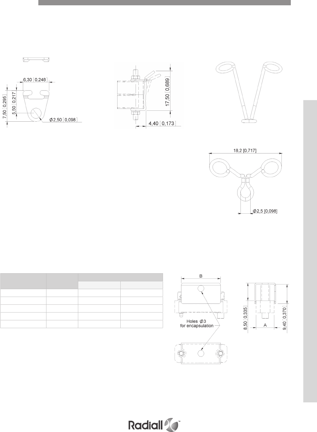
9-33
Our Most Important Connection is with You.™
Go online for data sheets & assembly instructions Visit www.radiall.com and enter the part number
SPRING LOCKING SYSTEM
This simple locking system avoids accidental disconnection of connectors fitted to equipment which may
be subjected to severe vibration. This system can be used where connector fitted with G1 guides are
used with or without backshell.
Part number of a pair: 624895
POTTING MOULDS
The plastic potting moulds are designed to fit onto the wiring side of the connectors in order so that the
wiring and back end can be encapsulated. They can be used with connectors fitted with G1 guides and
GV and VR jackscrews.
Contacts
Arrangements
Part
numbers
Type HA
A B
02 -03 624994 5.9 (0.232) 9.5 (0.374)
05 624992 5.9 (0.232) 13.5 (0.531)
07 624991 5.9 (0.232) 15.9 (0.626)
11 624993 9 (0.354) 15.9 (0.626)
14 624995 9 (0.354) 19 (0.748)
Accessories
MB SERIES

9-34
Our Most Important Connection is with You.™
Go online for data sheets & assembly instructions Visit www.radiall.com and enter the part number
Notes
MB SERIES

SECTION 10
RTX Series
EN3716

Our Most Important Connection is with You.™

SECTION 10 TABLE OF CONTENTS
10-3
Our Most Important Connection is with You.™
Go online for data sheets & assembly instructions Visit www.radiall.com and enter the part number
RTX series
Introduction ............................................................................................................... 10-4
Applications ............................................................................................................... 10-4
Product overview ......................................................................................................... 10-5
Technical characteristics ........................................................................................ 10-6 & 10-7
How to order connectors ................................................................................................ 10-8
Dimensions & Panel cut out ................................................................................... 10-9 & 10-10
RTX Terminations series
How to order connectors ............................................................................................... 10-11
Technical characteristics ............................................................................................... 10-11
Dimensions & Panel cut out ............................................................................................ 10-12
Twinax contacts ................................................................................................ 10-13 to 10-14
Tools ....................................................................................................................... 10-15
Contents
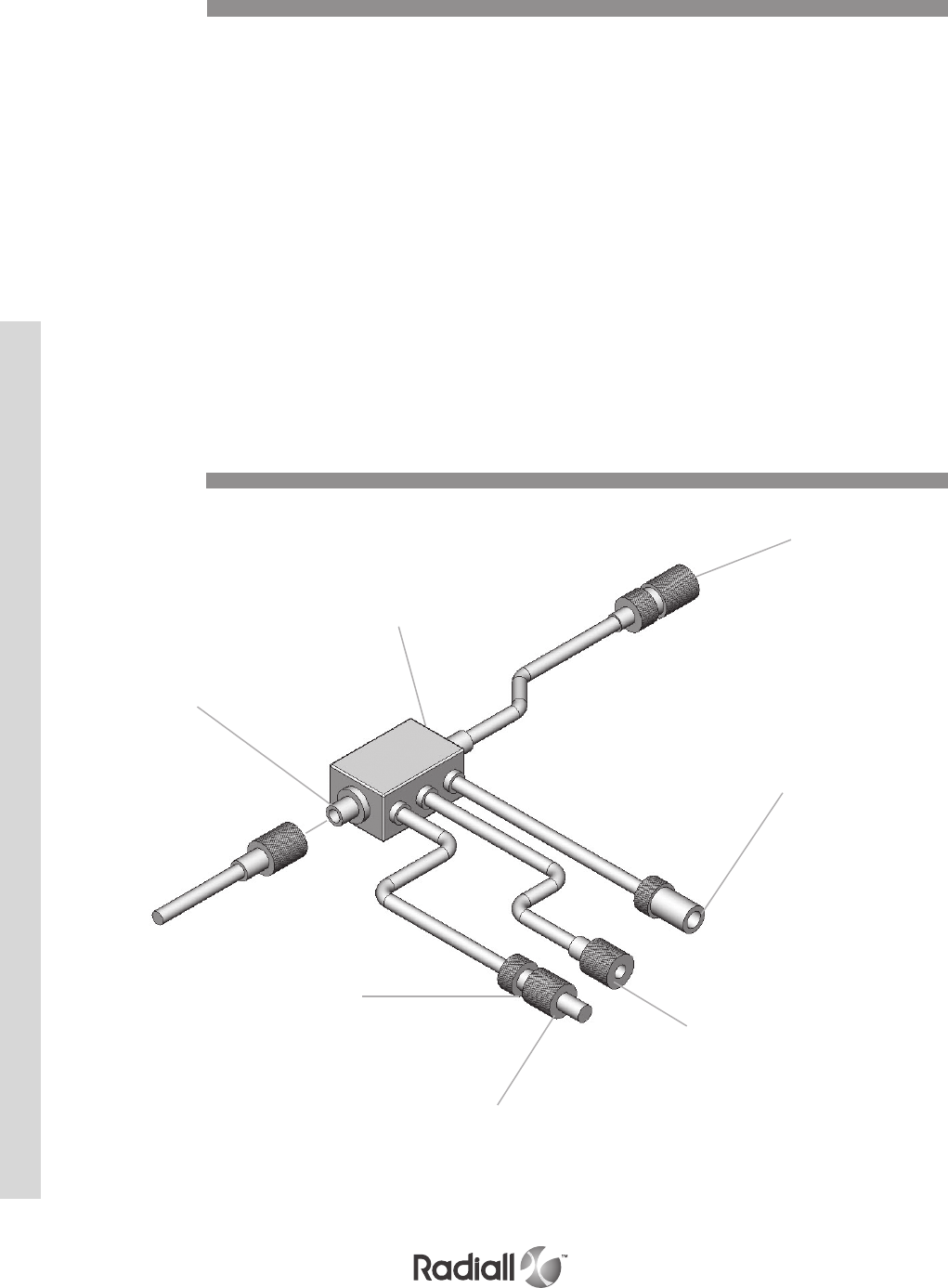
RTX SERIES
10-4
Our Most Important Connection is with You.™
Go online for data sheets & assembly instructions Visit www.radiall.com and enter the part number
The digital data bus defined by MIL-STD-1553B is commonly considered as a worldwide standard
regarding digital avionics equipment such as navigation by radar, communications, weapon control
systems, etc.
All these systems linked together exchange data through a network of “shielded twisted pairs,”
transformer couplers and twinax connectors.
Radiall offers the RTX range of twinax connectors, contacts and terminations suitable for use on this
digital data bus.
In addition, Radiall can supply twinax contacts for installation into multipin connectors to connect
equipment to the data bus.
NSX Arinc 600
EPX EN4644
MPX MIL DTL-83527B / EN3682
DSX SAE AS81659 / Arinc 404
MIL-DTL-38999
Coupler
Twinax
connector
(receptacle)
End of line
terminations
(77Ω)
Twinax contacts
EPX series
MPX series
DSX series
NSX series
38999, I, III, IV series
Twinax
connector
(plug)
Stimulated user
termination
(3000Ω)
Twinax
connector
(receptacle)
Introduction
Applications
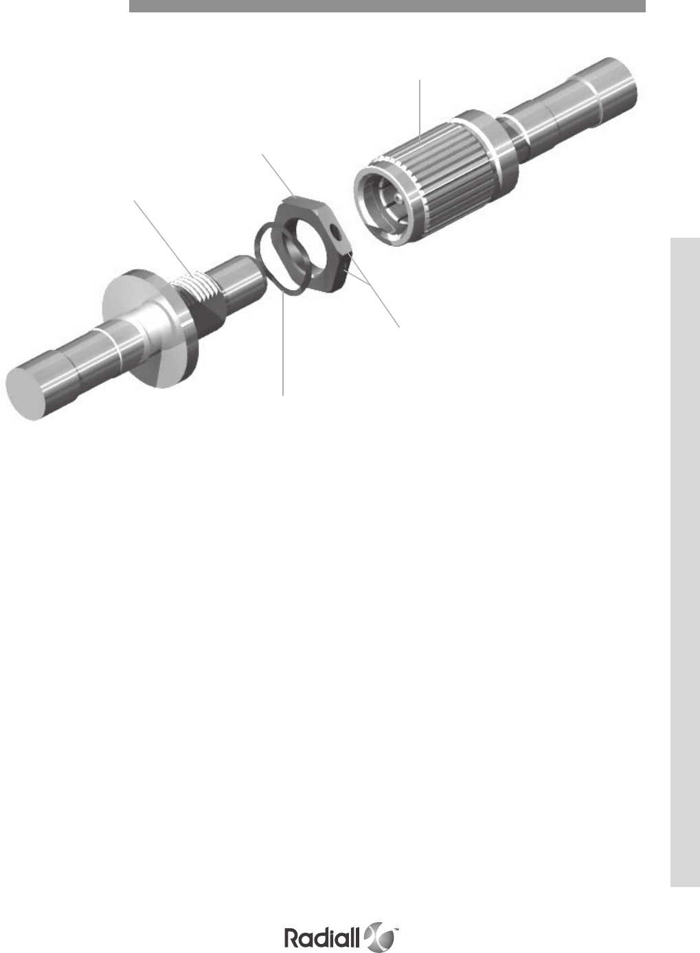
RTX SERIES
10-5
Our Most Important Connection is with You.™
Go online for data sheets & assembly instructions Visit www.radiall.com and enter the part number
Detailed view of the various parts of the RTX series connector.
Panel nut
Receptacle
Washer
Holes for safety wire
Plug
Product Overview

RTX SERIES
10-6
Our Most Important Connection is with You.™
Go online for data sheets & assembly instructions Visit www.radiall.com and enter the part number
ELECTRICAL
Frequency range: 5 MHz max
Insulation resistance:
@ 25°C (77°F) ≥ 5000 MΩ
@ 150°C (302°F) ≥ 1000 MΩ
DWV (sea level): 900 Vac RMS – 50 Hz
DWV (70000feet): 200 Vac RMS – 50 Hz
Contact resistance:
Center and intermediate contacts: ≤35 mΩ
Outer body: ≤8 mΩ
MECHANICAL & ENVIRONMENTAL
Temperature range: -65°C (-149°F) to +150°C (+302°F)
Temperature life: 1000 hours at 150°C (+302°F)
Salt spray: 500 hours
Altitude immersion: 47 kPa (.68 psi)
Air leakage: 0,5cm3/s
Sand and dust: 1 cycle – wind speed 3,5±0,5m/s
Humidity: 28 days
Shock: 100g – 6 ms
Vibration: AECMA EN2591 test D3 – method B
Mating & unmating: 500 cycles
Contact retention: > 45 N
Locking torque (C)
Mating: 1 ≤ C ≤ 1.25 N.m (8.85 ≤ C ≤ 11 Lb.inch)
Unmating: C ≤ 1.35 N.m (11.95 Lb.inch)
RoHs statue: Not RoHs
Technical Characteristics

RTX SERIES
10-7
Our Most Important Connection is with You.™
Go online for data sheets & assembly instructions Visit www.radiall.com and enter the part number
MATERIALS
WEIGHT
Description Material / Finish
Coupling ring Tin-lead plated brass
Plug outer body Copper alloy tin-lead plated
Receptacle outer body Tin-lead plated brass
Center contact and crimp pot Copper alloy gold over nickel
Ferrule Nickel plated brass
Insulator and sheath PTFE
Description Weight g (oz)
Plug 12 (0.423)
Receptacle 9 (0.317)
Technical Characteristics
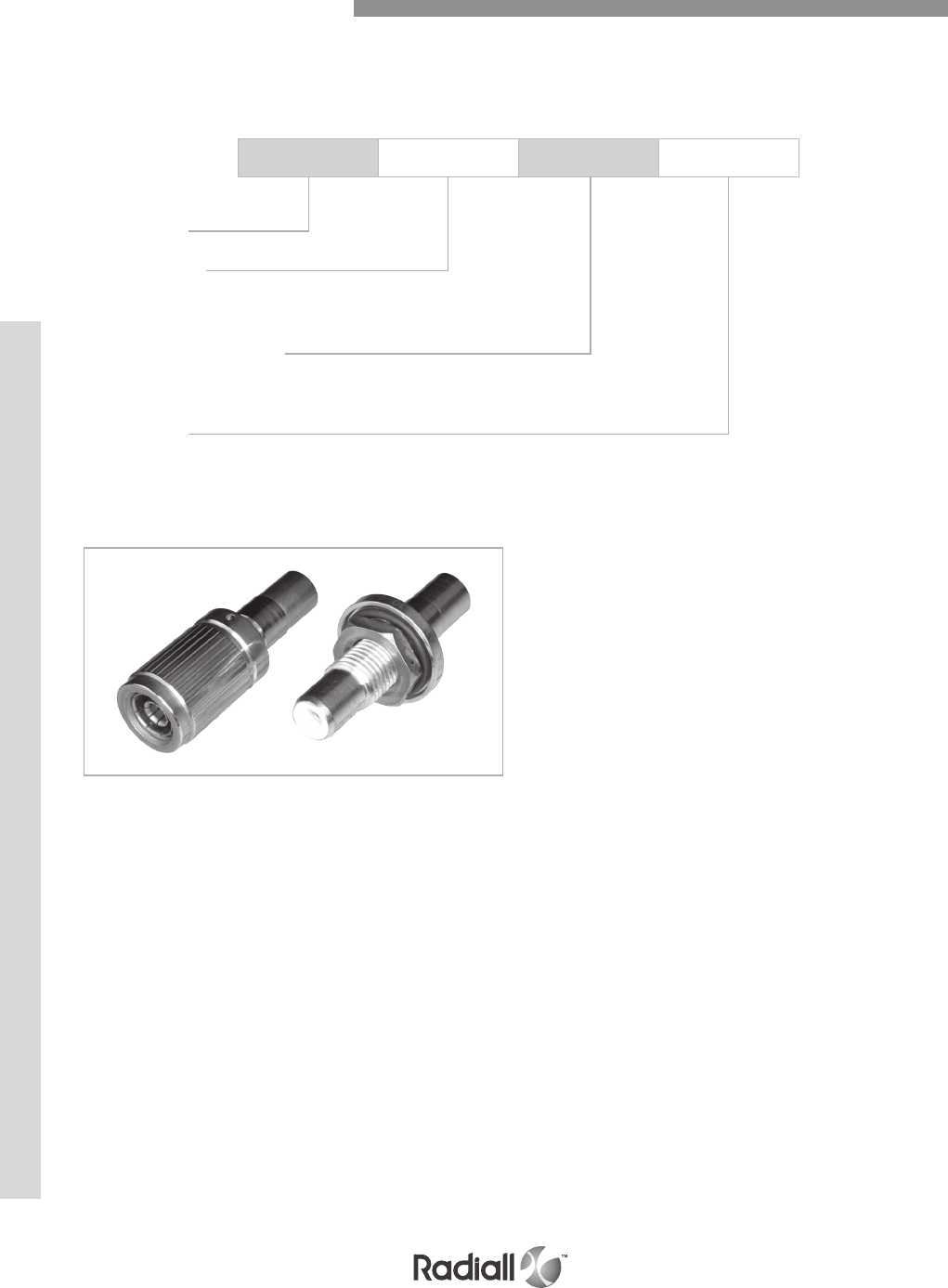
RTX SERIES
10-8
Our Most Important Connection is with You.™
Go online for data sheets & assembly instructions Visit www.radiall.com and enter the part number
The RTX series consists of plugs, receptacles (crimp version) and terminations.
The plug has a knurled and threaded coupling ring which provides mating and locking.
The jam nut style receptacle is provided with an o-ring for sealing to the bulkhead.
RTX 004 F01
Series prefix
Connector type
003: Receptacle
004: Plug
Intermediate contact type
F: Socket
M: Pin
Cable type (1)
01: Twisted pair single braid
02: Twisted pair double braid
NOTES:
(1) A version for triaxial cable is also available, please consult Radiall
How to Order RTX Connectors

RTX SERIES
10-9
Our Most Important Connection is with You.™
Go online for data sheets & assembly instructions Visit www.radiall.com and enter the part number
RECEPTACLE – PIN mm (inch)
RTX003M - -
PANEL CUT OUT
RECEPTACLE – SOCKET mm (inch)
RTX003F - -
Dimensions & Panel Cut Out
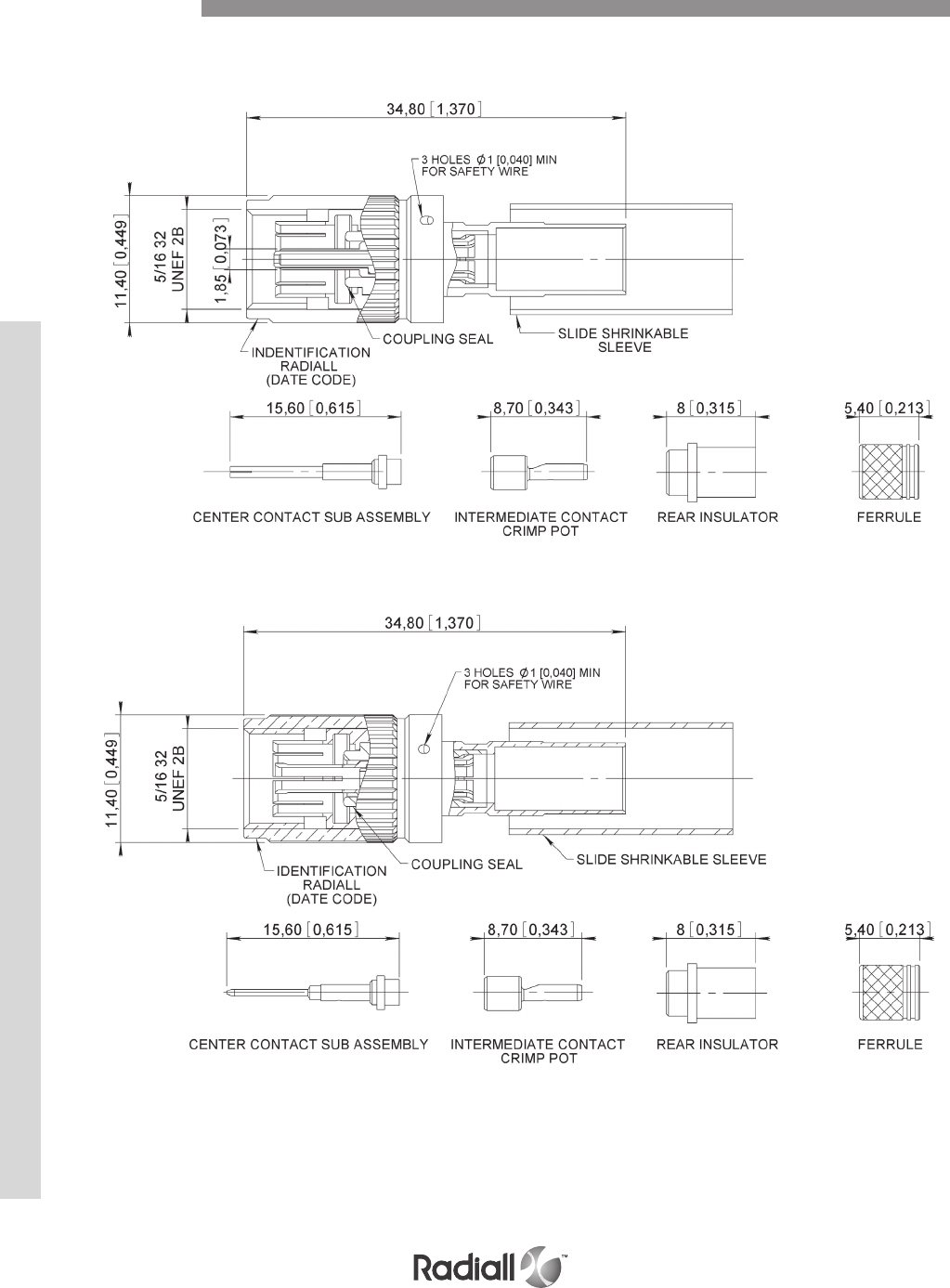
RTX SERIES
10-10
Our Most Important Connection is with You.™
Go online for data sheets & assembly instructions Visit www.radiall.com and enter the part number
PLUG – PIN mm (inch)
RTX004M --
PLUG – SOCKET mm (inch)
RTX004F --
Dimensions

RTX SERIES
10-11
Our Most Important Connection is with You.™
Go online for data sheets & assembly instructions Visit www.radiall.com and enter the part number
RTX series terminations are used to simulate a bus user or as end of line load.
RTX series terminations have the same technical characteristics as the RTX plug and receptacle except
the following:
Termination values: 77 ± 5 Ω or 3000 ± 60 Ω
DWV: 700 Vac RMS – 60Hz
Working voltage: 120 Vac RMS – 60 Hz
RTX 004 F770
Series prefix
Connector type
003: receptacle
004: plug
Intermediate contact type
F: socket
M: pin
Termination value (1)
770: end of line terminations (77Ω)
302: simulated user terminations (3000Ω)
NOTES:
(1) Write the two first significant digits of the resistance value plus 1 digit giving the number of zeros of the resistance value
(i.e. 5500 will be written 552)
How to Order RTX Terminations
Technical Characteristics
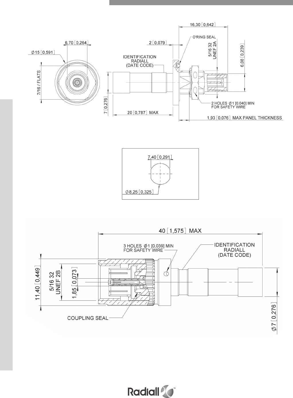
RTX SERIES
10-12
Our Most Important Connection is with You.™
Go online for data sheets & assembly instructions Visit www.radiall.com and enter the part number
RECEPTACLE TERMINATION mm(inch)
RTX003 --
PANEL CUT OUT
PLUG TERMINATION mm(inch)
RTX004 --
Dimensions RTX Terminations
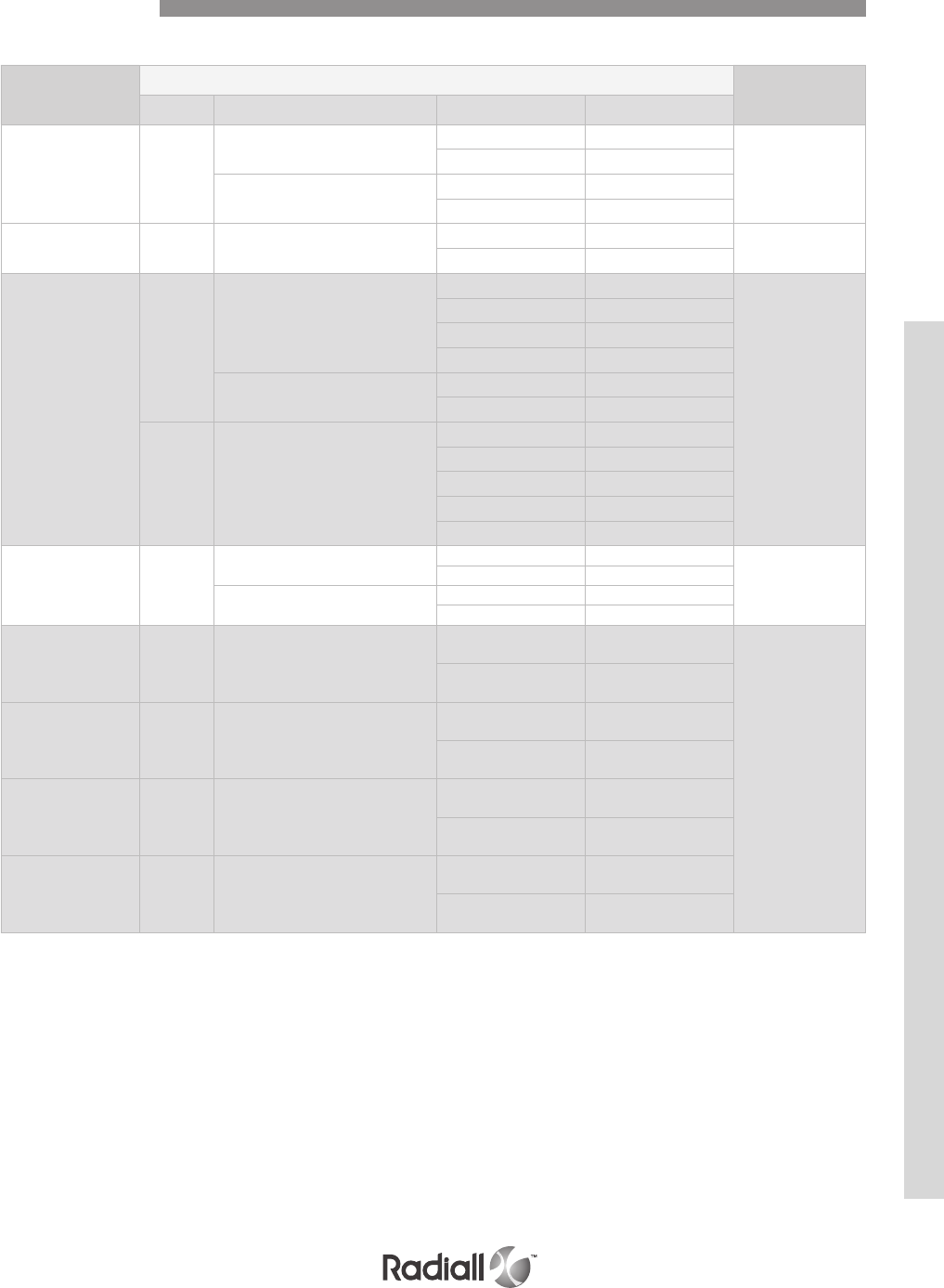
RTX SERIES
10-13
Our Most Important Connection is with You.™
Go online for data sheets & assembly instructions Visit www.radiall.com and enter the part number
CRIMP TERMINATION
Connector
series
Contact Insertion/Extraction
tool
Size Cable Type Part Number
MIL DTL
38999 8
MIL-C17/176000002
EN3375-003ST
Socket 670050 (1)
282549001
M81969/28-03
Pin 670150 (1)
EN3375-004DT
Or EN3375-005DT
Socket 670051 (1)
Pin 670151 (1)
EPX EN 4644 5 MIL-C-17/17600002
or PAN 6421
Socket 617050 282946
M81969/28-01
Pin 617150
DSX
ARINC 404
SAE AS81659
5
MIL-C-17/17600002
Socket 616095001 (3)
282946
M81969/28-01
Pin 616195001 (3)
Socket 616095009 (2)
Pin 616195009 (2)
PAN 6421 Socket 616095005 (3)
Pin 616195005 (3)
9 MIL-C-17/17600002
Socket 616096003 (3)
Pin 616196003 (3)
Socket 616096004 (2)
Pin 616196004 (2)
Socket 616096006 (2)
MPX
MIL DLT 83527B 8
EN3375-004DT
EN3375-005DT
Socket 618060 (1)
282549001
M81969/28-03
Pin 618160 (1)
MIL-C-17/17600002 or
EN3375-003ST
Socket 618061 (1)
Pin 618161 (1)
ARINC 8 MIL-C-17/17600002 or
EN3375-003ST
Socket 619070001 /
002 (env)
282549001
M81969/28-03
Pin 619170001/
002 (env)
ARINC 8 PAN6421ZA002
Socket 619070011 /
012 (env)
Pin 619170011/
012 (env)
ARINC 8
EN3375-004
Raychem 10613
ASNE0479WJ
Socket 619070021 /
022 (env)
Pin 619170021/
022 (env)
ARINC 8 10614 Triple shielded
Socket 619070031 /
032 (env)
Pin 619170031/
032 (env)
Notes:
(1) In order to have environmental versions add 001 to the part number except for 619x70xxx contacts
(2) These contacts are to be installed in environmental connectors only
(3) These contacts are to be installed in non environmental connectors only
Twinax Contacts
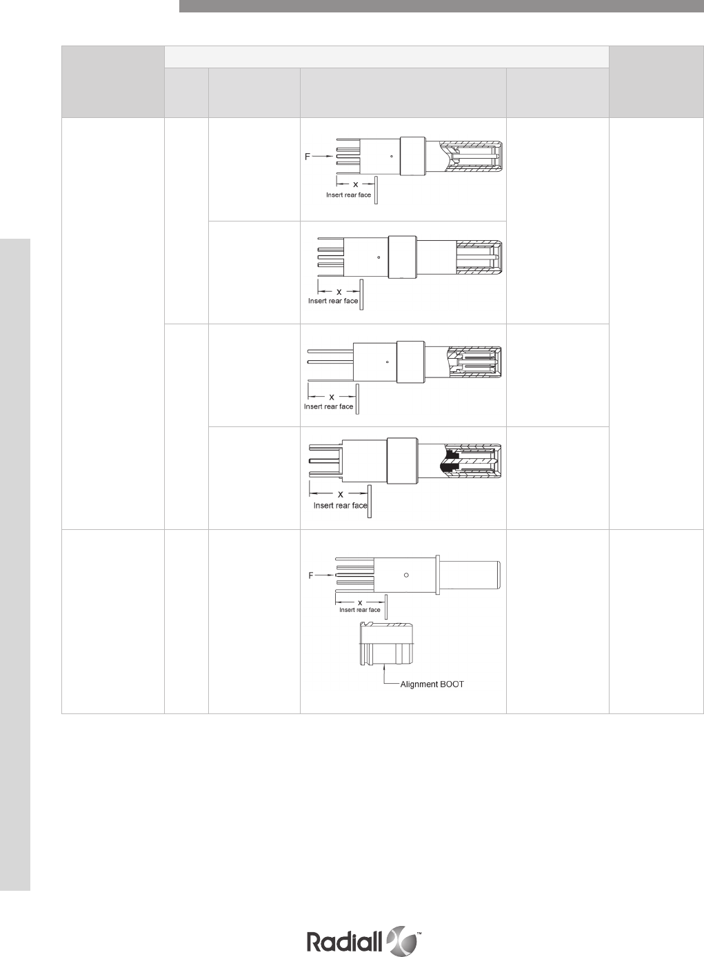
RTX SERIES
10-14
Our Most Important Connection is with You.™
Go online for data sheets & assembly instructions Visit www.radiall.com and enter the part number
PC TAIL TERMINATIONS
Notes:
(1) For 62T2 contact arrangement, the rear extension from the insert is .303/.343 (8.2 ± 0.5). This contact is delivered with an alignment boot
Connector
series
Contact
Insertion/Extraction
tool
Pin Size Part number Contact drawing
Rear
extension
from insert = X
mm (inch)
DSX
ARINC 404
SAE AS81659
5
616195003 32C2, 32T2, 33C4,
33T4, 40C1, 40T1
= 3.2/4.0
(.125/.158) 36C7,
36T7
= 5.40/6.10
(.212/.240)
282946
M81969/28-01
616195008
9
616196005
C8, T8
= 1.30/2.15
(.050/.085)
32C4, 32T4
= 6.45/7.30
(.253/.288)
616196007
C8, T8 = 0
32C4, 32T4
= 3.70/4.35
(.145/.170)
MPX
MIL DLT 83527B 8 618163 (1) 7.65 ± 0.5
(.282/.321)
282549001
M81969/28-03
Twinax Contacts

RTX SERIES
10-15
Our Most Important Connection is with You.™
Go online for data sheets & assembly instructions Visit www.radiall.com and enter the part number
INSERTION / EXTRACTION TOOL
282946 - M81969/28-01
282549001 - M81969/28-03
Tools

RTX SERIES
10-16
Our Most Important Connection is with You.™
Go online for data sheets & assembly instructions Visit www.radiall.com and enter the part number
Notes
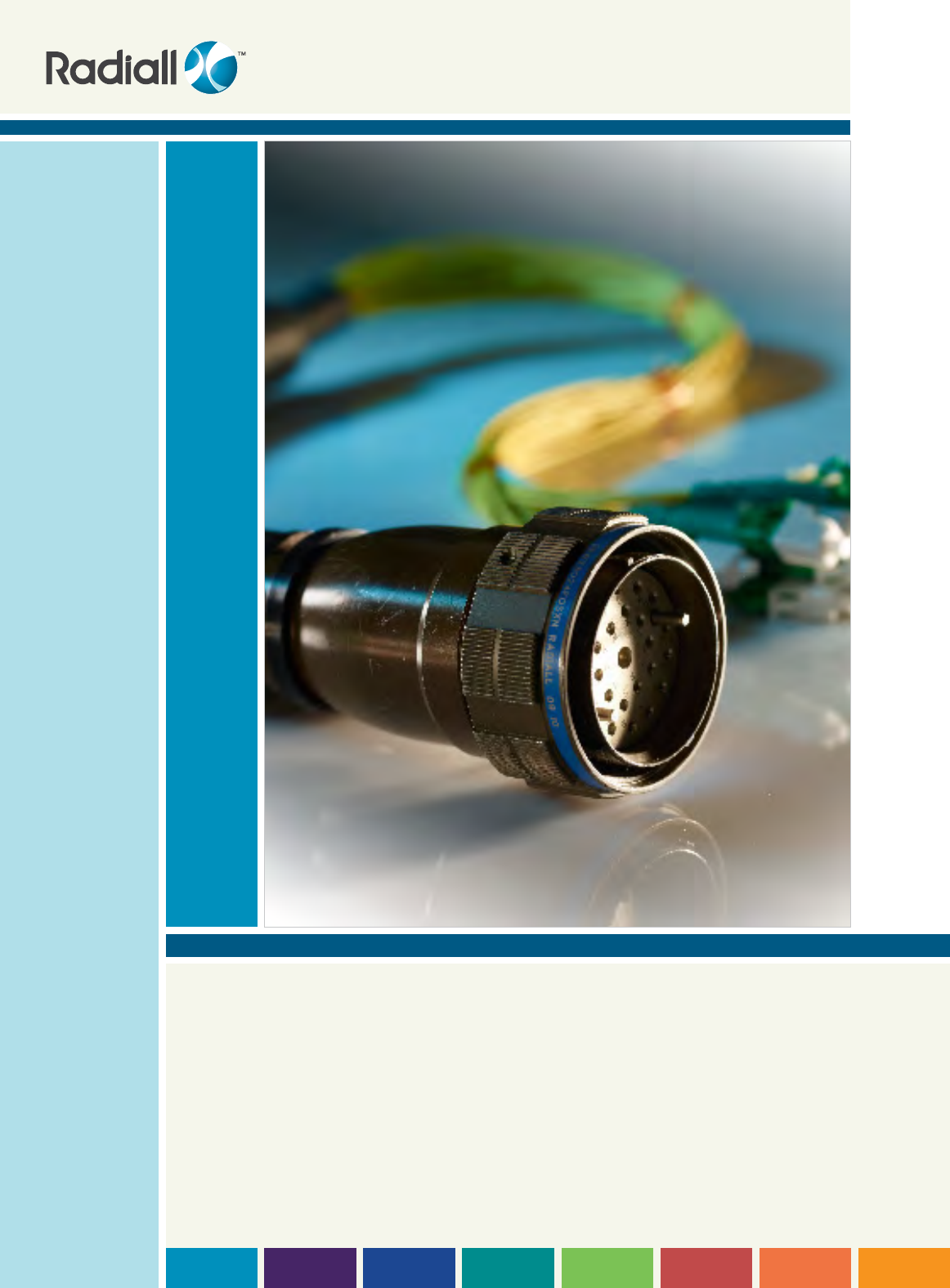
SECTION 11
MIL-DTL 38999 Type Connectors

Our Most Important Connection is with You.™

11-3
Our Most Important Connection is with You.™
Go online for data sheets & assembly instructions Visit www.radiall.com and enter the part number
Introduction & Application ..................................................................................................... 11-4
Product overview ...............................................................................................................11-5
How to order MIL-DTL-38999 type connectors ..............................................................................11-6
Inserts for LuxCis® contacts ................................................................................................. 11-7
LuxCis® Fiber Optic Contacts ................................................................................................ 11-8
Quadrax & Coaxial Contacts ..................................................................................................11-9
Shell dimensions .............................................................................................................11-10
Contents
SECTION 11 TABLE OF CONTENTS
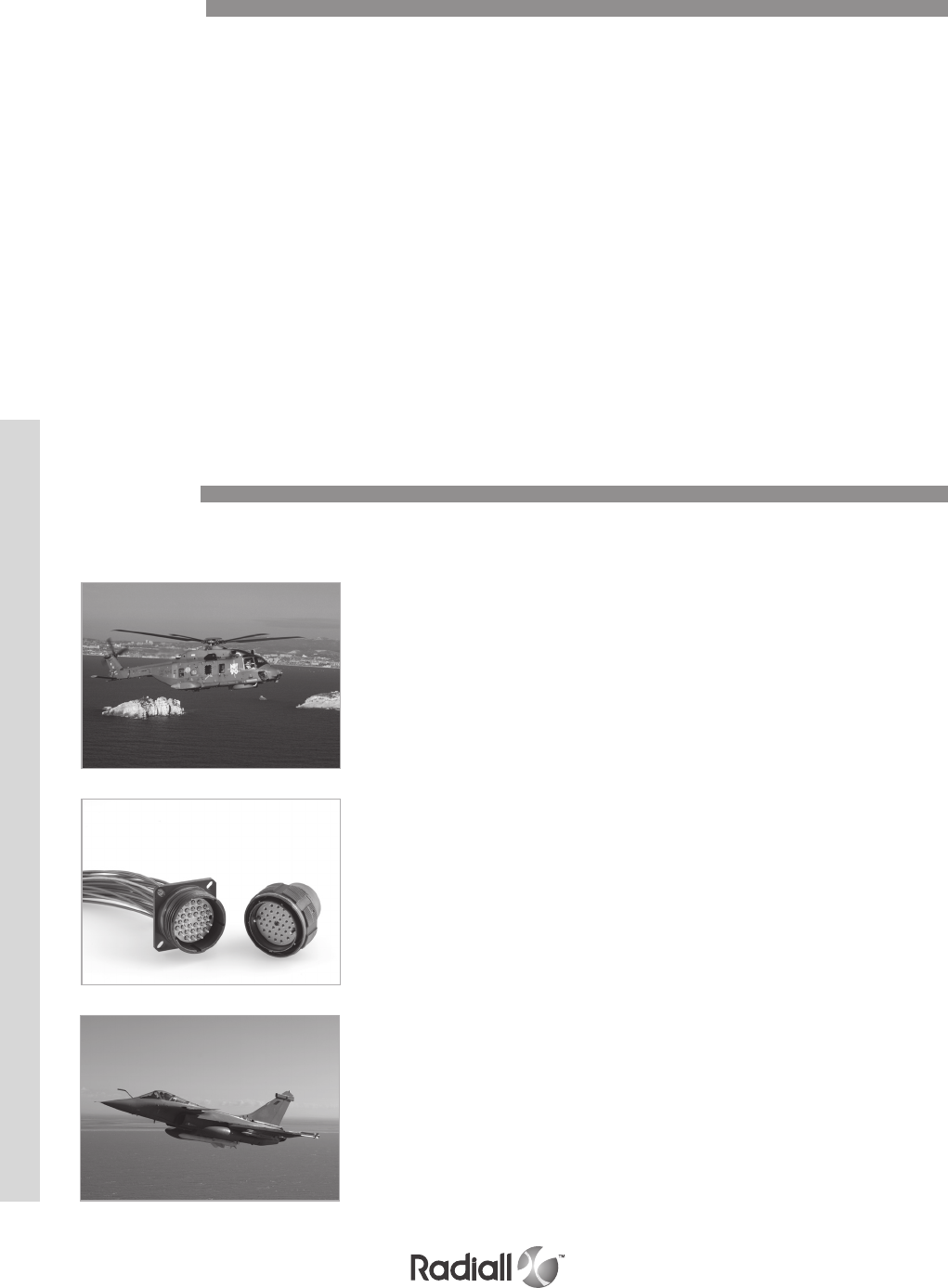
MIL-DTL-38999
11-4
Our Most Important Connection is with You.™
Go online for data sheets & assembly instructions Visit www.radiall.com and enter the part number
Radiall offers a wide range of MIL-DTL-38999 type connectors for applications in both military
and civil aviation markets.
Whether your needs are for crimped coax or quadrax contacts, or for LuxCis® optical contacts,
you will find products that suit your requirements.
Radiall proposes various sizes (from 11 to 25), types (plugs, wall-mount & jam-nut receptacles),
and plating for 38999 type shells to withstand high performances:
- Aluminum Olive drab Cadmium (500h salt spray)
- Nickel plated Aluminum (48h salt spray)
- Nickel plated Composite (2000h salt spray)
- Nickel Aluminum Bronze (500h salt spray)
Radiall also provides an extensive range of inserts: nine optical arrangements including one that mixes
electrical and optical contacts.
Apart from our LuxCis contacts range, you will also find Radiall’s Quadrax & Coaxial contact offer,
for environmental and non-environmental needs.
Introduction
Application
Interconnect solution for aerospace and military harsh environment applications.
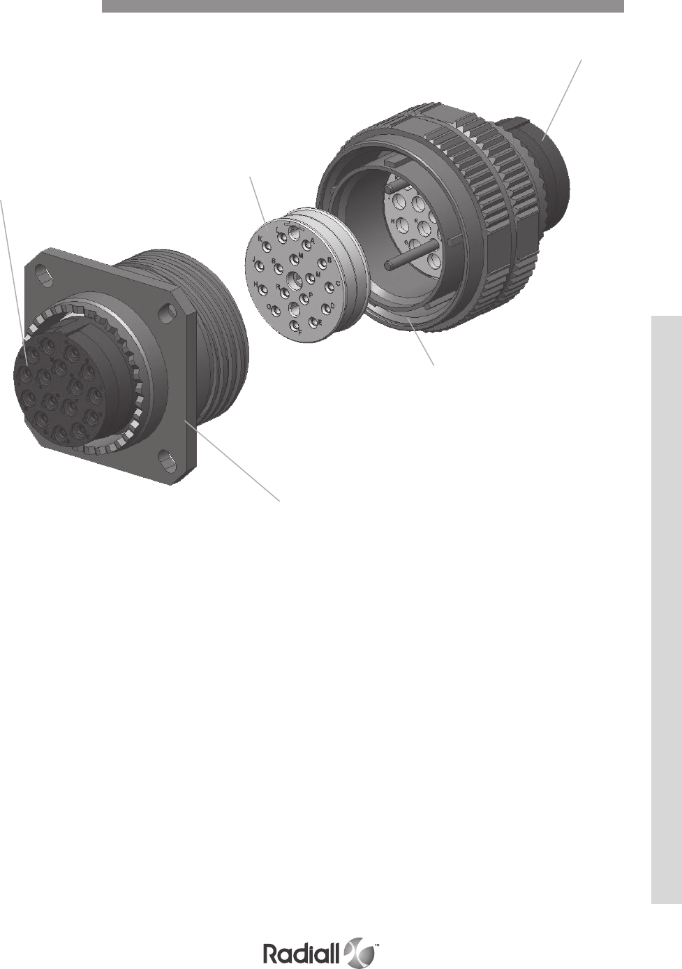
MIL-DTL-38999
11-5
Our Most Important Connection is with You.™
Go online for data sheets & assembly instructions Visit www.radiall.com and enter the part number
Product Overview
Rear grommet
Rear grommet
#21 sleeve holder
Plug shell
Wall-mount receptacle shell
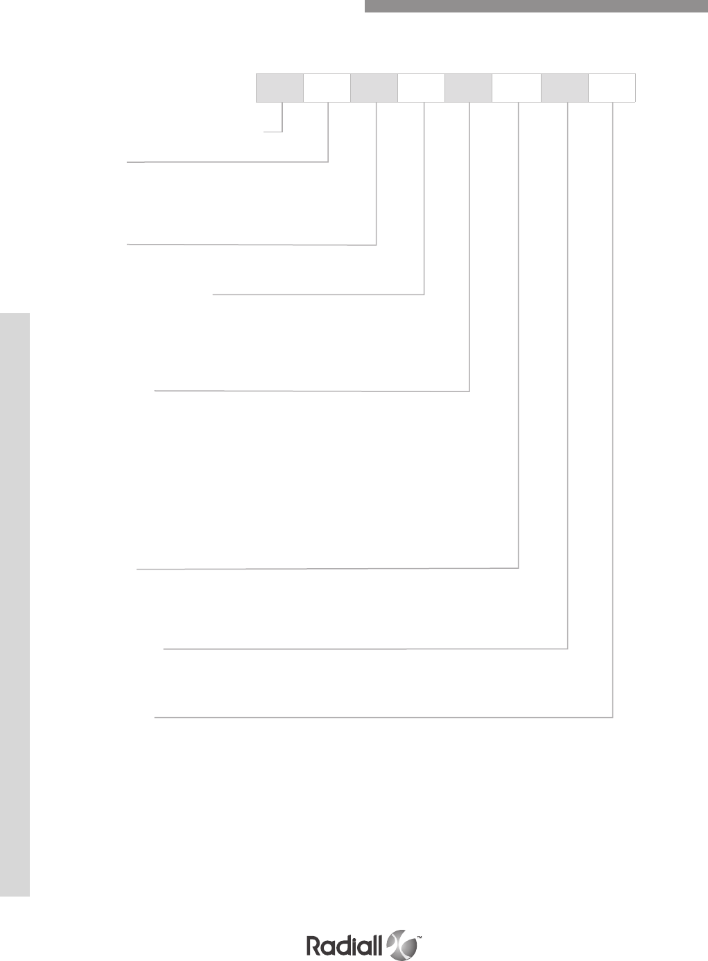
MIL-DTL-38999
11-6
Our Most Important Connection is with You.™
Go online for data sheets & assembly instructions Visit www.radiall.com and enter the part number
R8: LuxCis® MIL-DTL-38999 series
Shell type:
W: Plug
R: Square flange receptacle
N: Jam nut receptacle
Shell size:
11-13-15-17-19-21-23-25
Shell material and finish:
O: Aluminium olive drab cadmium
N: Nickel plated Aluminium
M: Nickel plated composite
G: Nickel aluminium bronze
Contact layout:
2FO: 2 LuxCis® contacts (shell size 11)
2FO2E: 2 LuxCis® + 2 electrical contacts (shell size 13)
4FO: 4 LuxCis® contacts (shell size 13)
6FO: 6 LuxCis® contacts (shell size 15)
8FO: 8 LuxCis® contacts (shell size 17)
12FO: 12 LuxCis® contacts (shell size 19)
16FO: 16 LuxCis® contacts (shell size 21)
24FO: 24 LuxCis® contacts (shell size 23)
32FO: 32 LuxCis® contacts (shell size 25)
Insert type:
S: Sealed insert for plug (R8W)
P: Sealed insert for receptacle
(R8R or R8N)
Insert material:
A: Anodized aluminium
C: Non metalized composite
Polarization:
N-A-B-C-D-E
How to order MIL-DTL-38999 type connectors
Electrical contacts are to be ordered separately
Anodized aluminum inserts are recommended when specific EMI protection is required
All connectors are supplied with a plastic cap
Accessories such as backshell or metalized caps are only available for harness assemblies
manufactured by Radiall.
Please contact your sales representative for other plating alternatives or for specific requirements
PART NUMBERS FOR LUXCIS® MIL-DTL-38999 TYPE CONNECTORS
R8 W 15 0 6F0 S A N
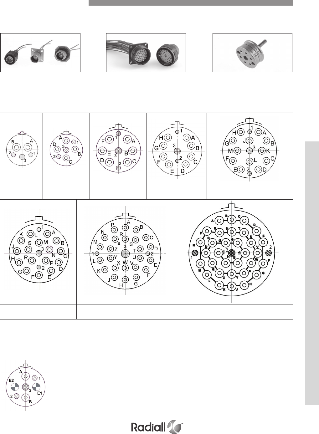
MIL-DTL-38999
11-7
Our Most Important Connection is with You.™
Go online for data sheets & assembly instructions Visit www.radiall.com and enter the part number
Size 11,
2 LuxCis®
Size 13,
4 LuxCis®
Size 15,
6 LuxCis® Size 17, 8 LuxCis® Size 19, 12 LuxCis®
Size 21, 16 LuxCis® Size 23, 24 LuxCis® Size 25, 32 LuxCis®
MIL-DTL-38999 TYPE CONNECTORS FOR LUXCIS® CONTACT
The LuxCis® product range also includes MIL-DTL-38999 type connectors
Size 11 MIL-DTL-38999
type connectors
Size 25 MIL-DTL-38999
type connectors
Size 13 connector with 2 electrical and 2 LuxCis® cavities
Hybrid connectors are available in all sizes; please see
your local Radiall representative for more details.
Removable sleeveholder
for easy access to the
ferrules and sleeves for
inspection and cleaning
Inserts for LuxCis® contacts
SHELLS ARRANGEMENT
1 & 2: Alignment pins 3: Sleeve-holder screw A, B, … : Optical cavities
All views show the front face of a plug.
The LuxCis® product range also includes hybrid connectors, mixing electrical and LuxCis® cavities.
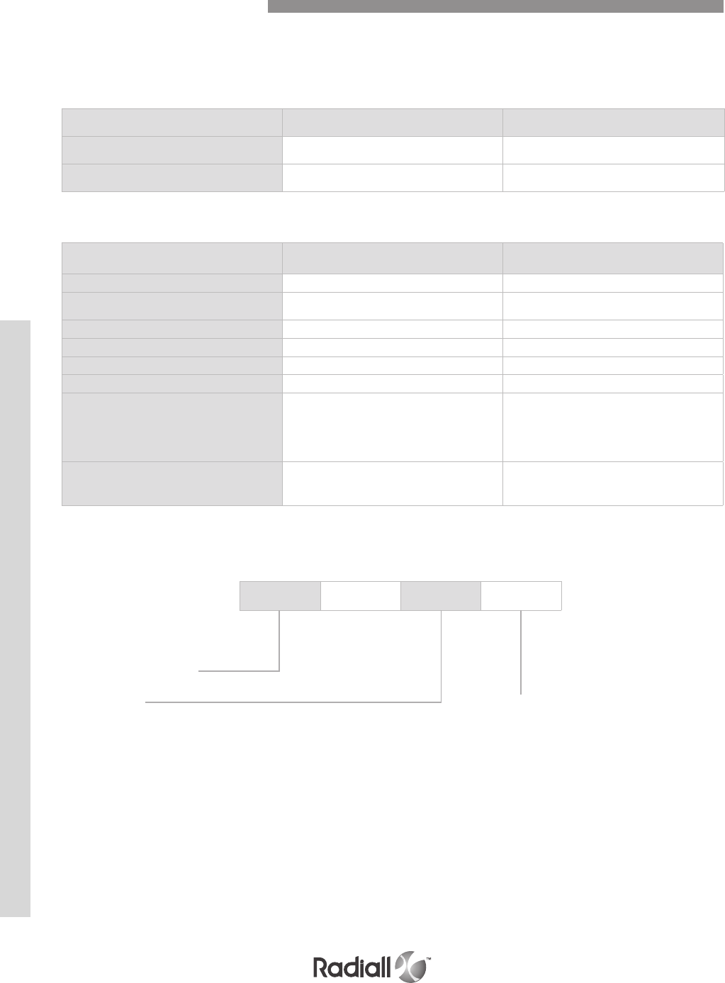
MIL-DTL-38999
11-8
Our Most Important Connection is with You.™
Go online for data sheets & assembly instructions Visit www.radiall.com and enter the part number
The LuxCis® product range is a proven, flexible and always expending fiber optic interconnect solution
offering high speed communication in aerospace and other harsh environments.
NOTE:
Radiall can support you with your cable and harness assemblies
Please contact your sales representative
OPTICAL PERFORMANCES
MECHANICAL AND ENVIRONMENTAL CHARACTERISTICS
MultiMode (PC)
850 / 1300 nm
SingleMode (UPC)
1310 / 1550 nm
Insertion Loss (IL) Mean
(IEC 61300-3-4 Method B)
0.1 dB 0.15 dB
Return Loss (RL)
(IEC 61300-3-6)
> 20 dB > 50 dB
Standard Performances
Thermal cycling
SAE AS 13441 method 1003.1 -55°C/+125°C (cable dependant)
Temperature
endurance
TIA/EIA 455-20 1000 h @ 125°C (cable dependant)
Vibration
TIA/EIA 455-11 43 Grms
Shocks
TIA/EIA 455-14 330 G, 3 ms
Durability
TIA / EIA 364-09 500 cycles
Maintenance ageing
SAE AS 13441 method 2002.1 10 cycles
Cable retention
1.8 mm diameter
900 µm diameter
SAE AS 13441 method 2009.1 68 N
7 N
Humidity
TIA EIA 455-5
10 cycles / 24 h
90% RH
-25°C / +65°C
LUXCIS® CONTACT PART NUMBERING SYSTEM
F725 0 03 419
Cable type and diameter
118:
900 µm cable
318: 1.2 mm cable with strengthening
members, tight structure
419: 1.6 to 2.2 mm cable, loose structure
519: 1.6 to 2.2 mm cable, tight structure
F725: LuxCis® series
Ferrule type
00:
PC ferrule for SingleMode fiber
03: PC ferrule for 50/125 or 62,5/125 um MultiMode fiber
04: PC ferrule for 100/40 um MultiMode fiber
05: PC ferrule for 200/230 um MultiMode fiber
50: APC ferrule for SingleMode fiber
LuxCis® Fiber Optic Contacts
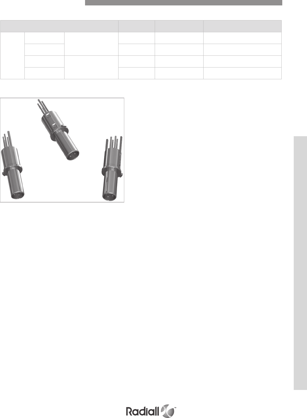
MIL-DTL-38999
11-9
Our Most Important Connection is with You.™
Go online for data sheets & assembly instructions Visit www.radiall.com and enter the part number
Quadrax & Coaxial Contacts
SIZE 8 QUADRAX & COAXIAL CONTACTS
Type Socket contact Pin contact Cable
Size 8
Quadrax
Environmental
670075023 670175023 Draka F 4703-2
Quadrax 670175012 670175012 Tensolite NF 24 Q 100
Quadrax
Non- Environmental
670075028 /Tensolite NF 24 Q 100
Coax 670001007 670101007 EN3645 EN4165
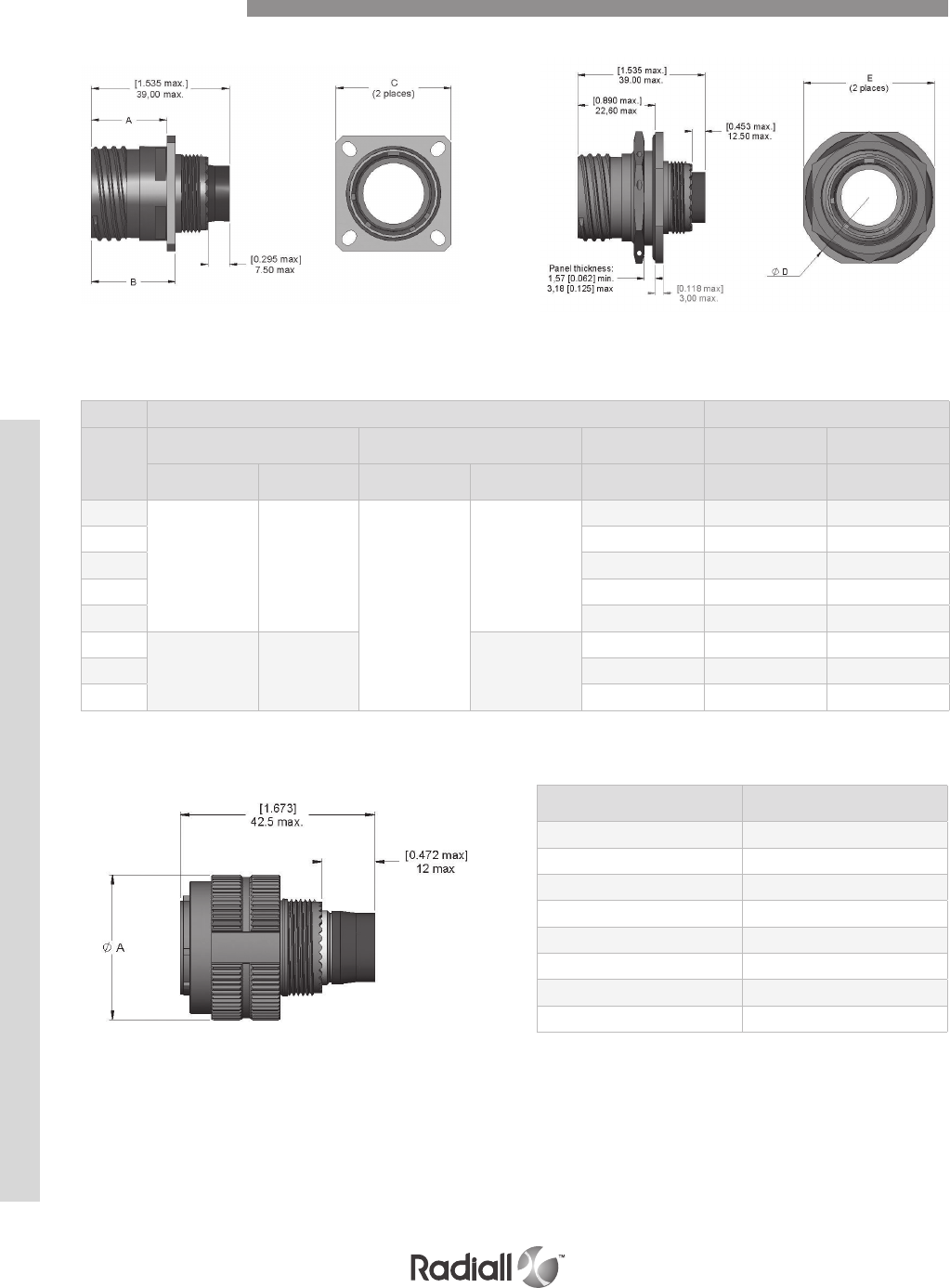
MIL-DTL-38999
11-10
Our Most Important Connection is with You.™
Go online for data sheets & assembly instructions Visit www.radiall.com and enter the part number
SQUARE FLANGE AND JAM NUT RECEPTACLES
Fig. 1 Square flange receptacles Fig. 2 Jam nut receptacles
Shell Dimensions
PLUGS
Shell size Dia. A max.
mm (inch)
11 25.00 (0.984)
13 29.40 (1.157)
15 32.50 (1.280)
17 35.70 (1.405)
19 38.50 (1.516)
21 41.70 (1.642)
23 44.90 (1.768)
25 48.00 (1.890)
Figure 1 Figure 2
Shell
size
A max.
mm (inch)
B max.
mm (inch)
C max.
mm (inch) Dia. D max. E max.
Metallic
shell
Composite
shell
Metallic
shell
Composite
shell mm (inch) mm (inch)
11
20.83 (0.820) 19.69 (0.775)
23.15 (0.911)
23.19 (0.913)
26.50 (1.043) 35.20 (1.386) 32.20 (1.268)
13 28.90 (1.137) 38.40 (1.512) 35.30 (1.390)
15 31.30 (1.232) 41.60 (1.638) 38.50 (1.516)
17 33.70 (1.323) 44.80 (1.764) 41.70 (1.642)
19 36.90 (1.449) 49.50 (1.949) 46.40 (1.827)
21
20.07 (0.790) 18.92 (0.745) 23.14 (0.911)
40.10 (1.575) 52.70 (2.075) 49.60 (1.953)
23 43.30 (1.701) 55.90 (2.200) 52.80 (2.079)
25 46.40 (1.823) 59.00 (2.323) 56.00 (2.205)
Part Number Index
Multipin Connector Series
Part Number Index

Our Most Important Connection is with You.™

Our Most Important Connection is with You.™
INDEX
Radiall Part Numbers
11-3
Part Number Page Part Number Page Part Number Page Part Number Page
Go online for data sheets & assembly instructions. Visit www.radiall.com and enter the part number.
282236 .......................... 4-80
......................................5-27
......................................6-53
282246 .......................... 4-80
......................................5-27
...................6-23, 6-25, 6-53
282247 .......................... 4-80
............................ 6-23, 6-61
282248 .......................... 6-61
282281 ................ 1-17, 1-18
............................ 2-13, 2-14
..........4-34, 4-37, 4-38, 4-80
............................ 5-23, 5-27
..........6-25, 6-41, 6-50, 6-61
............................ 7-27, 7-35
............................ 8-19, 8-25
282291 ................ 1-17, 1-18
............................ 2-13, 2-14
...................4-34, 4-35, 4-80
......................................5-23
............................ 6-23, 6-61
......................................7-35
............................ 8-19, 8-25
282292 .......................... 4-80
......................................5-27
......................................6-25
...................7-26, 7-27, 7-35
............................ 8-19, 8-25
282293 .......................... 5-27
...................6-23, 6-25, 6-61
282296 .......................... 4-36
......................................5-23
......................................6-61
282297 .......................... 5-27
282500 ................ 4-60, 4-81
......................................5-24
............................ 6-41, 6-61
282503 ................ 4-59, 4-81
............................ 6-41, 6-61
282504 .......4-56, 4-60, 4-81
............................ 6-41, 6-61
282512 .......................... 1-19
......................................2-15
282515 .......1-17, 1-18, 1-23
..........2-13, 2-14, 2-13, 2-32
............................ 4-34, 4-55
282515 .......................... 5-23
282522 .......1-17, 1-18, 1-23
............................ 2-13, 2-14,
282527 .......................... 6-23
282546 ................ 4-34, 4-81
............................ 6-50, 6-61
282547 ................ 6-50, 6-61
282548 ................ 4-36, 4-81
282550 .......................... 4-80
......................................5-27
............................ 6-25, 6-61
282555 .......................... 4-80
......................................5-27
......................................6-25
282556 .......................... 4-80
......................................5-27
......................................6-25
282557 .......................... 4-36
......................................6-61
282572 .......................... 5-27
282579 ................ 4-35, 4-80
......................................5-23
............................ 6-61, 6-50
282581 .......................... 5-27
282586 .......................... 5-23
282587 .......................... 4-80
282588 .......................... 1-17
......................................2-13
............................ 4-36, 4-80
282613 .......................... 1-17
......................................2-13
282664 .......................... 1-47
......................................3-15
282665 .......................... 1-47
......................................3-15
282666 .......................... 1-47
282885 .................................
..........4-34, 4-37, 4-38, 4-81
......................................5-23
............................ 6-61, 6-50
282886 .......................... 1-17
......................................2-13
..........4-34, 4-37, 4-38, 4-81
............................ 6-50, 6-61
282890 ................ 4-57, 4-81
............................ 6-50, 6-61
282891 ................ 6-50, 6-61
282892 ................ 4-51, 4-81
......................................6-61
282920 ................ 7-25, 7-35
............................ 8-19, 8-25
282921 ................ 7-25, 7-35
282929 .......................... 6-61
282943 ................ 6-50, 6-61
282945 .......................... 4-81
......................................6-61
282946 .......1-17, 1-19, 1-23
............................ 2-13, 2-15
4-48, 4-49, 4-50, 4-51, 4-81
......................................6-61
........................ 10-13, 10-14
282948 ................ 6-61, 6-51
282949 ................ 6-61, 6-51
282959 .......................... 6-45
282970 ................ 1-17, 1-18
............................ 2-13, 2-14
...................4-34, 4-37, 4-38
......................................5-23
......................................6-50
282971 ................ 1-17, 1-18
............................ 2-13, 2-14
...................4-34, 4-37, 4-38
......................................5-23
......................................6-50
282972 ................ 1-17, 1-18
............................ 2-13, 2-14
...................4-34, 4-35, 4-80
......................................5-23
......................................6-50
282973 .......7-26, 7-27, 7-35
............................ 8-19, 8-25
282974 .......6-25, 6-41, 6-61
282975 .......................... 7-35
............................ 8-19, 8-25
282976 .......................... 7-35
............................ 8-19, 8-25
282981 .......7-26, 7-27, 7-35
282997 .......................... 4-80
............................ 6-23, 6-24
610026 .......................... 6-52
610040 .......................... 6-53
610044 .......................... 6-53
610046 .......................... 6-53
610047 .......................... 6-53
610049 .......................... 6-53
610108 .......................... 6-52
610118 .......................... 6-52
610119 .......................... 6-52
610120 ................ 6-25, 6-52
610122 .......................... 6-52
610123 .......................... 6-52
610126 ................ 6-25, 6-52
610127 .......................... 6-52
610140 .......................... 6-53
610146 .......................... 6-53
610147 .......................... 6-53
610148 .......................... 6-53
610149 .......................... 6-53
610203 .......6-23, 6-24, 6-51
610204 .......6-23, 6-24, 6-51
610214 .......6-23, 6-24, 6-51
610215 .......................... 6-51
610216 .......................... 6-50
610217 .......................... 6-51
610219 .......................... 6-50
610220 .......................... 6-50
610221 .......................... 6-50
610224 .......................... 6-51
610225 .......................... 6-51
610226 .......................... 6-50
610228 .......................... 6-51
610303 ................ 6-23, 6-51
610304 ................ 6-23, 6-51
610314 ................ 6-23, 6-51
610321 .......................... 6-50
610324 .......................... 6-51
610325 .......................... 6-50
610803 .......................... 6-29
610804 .......................... 6-29
610805 .......................... 6-29
610806 .......................... 6-29
610900 .......................... 6-30
610901 .......................... 6-30
610902 .......................... 6-30
610906 .......................... 6-30
610910 .......................... 6-30
610911 .......................... 6-30
610941 ................ 1-24, 6-53

11-4
Our Most Important Connection is with You.™
INDEX
Radiall Part Numbers
Part Number Page Part Number Page Part Number Page Part Number Page
Go online for data sheets & assembly instructions. Visit www.radiall.com and enter the part number.
612813 .......................... 8-22
612814 .......................... 8-23
612823 .......................... 8-22
612824 .......................... 8-23
612837 .......................... 8-22
612838 .......................... 8-23
612845 .......................... 8-22
612846 .......................... 8-23
614120 .......................... 8-19
614140 .......................... 8-19
614160 .......................... 8-19
614170 .......................... 8-19
614200 .......................... 8-19
614210 .......................... 8-19
614230 .......................... 8-19
614240 .......................... 8-19
614330 .......................... 8-19
614340 .......................... 8-19
616003 ................ 6-23, 6-24
616004 ................ 6-23, 6-24
616005 ................ 6-23, 6-24
616006 ................ 6-23, 6-24
616007 ................ 6-23, 6-24
616009 ................ 6-23, 6-24
616013 .......................... 6-25
616014 .......................... 6-25
616015 .......................... 6-25
616020 .......................... 6-25
616021 .......................... 6-25
616022 .......................... 6-25
616023 .......................... 6-25
616024 .......................... 6-25
616026 .......................... 6-25
616028 .......................... 6-25
616030 ................ 6-25, 6-26
616031 ................ 6-25, 6-26
616032 ................ 6-25, 6-26
616040 ................ 6-25, 6-26
616041 ................ 6-25, 6-26
616042 ................ 6-25, 6-26
616043 ................ 6-25, 6-26
616044 ................ 6-25, 6-26
616090 .......................... 6-45
616091 .......................... 6-45
616092 .......................... 6-45
616100 ................ 6-23, 6-24
616106 ................ 6-23, 6-24
616111 .......................... 6-25
616112 .......................... 6-25
616113 .......................... 6-25
616120 .......................... 6-25
616121 .......................... 6-25
616122 .......................... 6-25
616123 .......................... 6-25
616124 .......................... 6-25
616125 .......................... 6-25
616126 .......................... 6-41
616127 .......................... 6-41
616128 .......................... 6-25
616140 ................ 6-25, 6-26
616141 ................ 6-25, 6-26
616142 ................ 6-25, 6-26
616143 ................ 6-25, 6-26
616144 ................ 6-25, 6-26
616150 ................ 6-25, 6-26
616151 ................ 6-25, 6-26
616153 ................ 6-25, 6-26
616154 ................ 6-25, 6-26
616163 .......................... 6-25
616192 .......................... 6-45
616200 ................ 6-36, 6-50
616201 ................ 6-22 ,6-50
616206 ................ 6-23, 6-50
616210 ........6-22,6-36, 6-50
616211 ................ 6-22, 6-50
616216 .......................... 6-23
616220 .......................... 6-41
616222 .......................... 6-41
616223 .......................... 6-23
616224 .......................... 6-41
616230 .......6-22, 6-36, 6-50,
616231 ................ 6-22, 6-50
616234 .......................... 6-41
616235 .......................... 6-41
616240 .......6-22, 6-36, 6-50
616261 .......................... 6-22
616261 .......................... 4-36
616266 ................ 4-36, 6-22
616300 ................ 6-22, 6-36
616301 ................ 6-22, 6-50
616303 ................ 6-23, 6-50
616306 ................ 6-23, 6-50
616310 .......6-22, 6-36, 6-50
616311 ................ 6-22, 6-50
616323 .......................... 6-23
616330 ................ 6-36, 6-50
616331 ................ 6-22, 6-50
616340 .......6-22, 6-36, 6-50
616361 .......................... 4-36
......................................6-22
616366 .......................... 6-22
616366 .......................... 4-36
616379 ................ 6-23, 6-50
616910 ................ 1-24, 1-64
......................................4-84
......................................5-33
............................ 6-28, 6-36
616911 .......................... 1-24
......................................4-84
......................................5-33
............................ 6-28, 6-36
616912 .......................... 1-24
......................................4-84
......................................5-33
............................ 6-28, 6-36
616913 .......................... 1-24
......................................4-84
......................................5-33
............................ 6-28, 6-36
616915 .......................... 6-28
616917 .......................... 6-28
616923 ................ 6-28, 6-53
617001 .......................... 1-19
......................................2-15
617002 .......................... 1-19
......................................2-15
617003 .......................... 1-19
......................................2-15
617004 .......................... 1-19
......................................2-15
617005 .......................... 1-19
......................................2-15
617030 .......................... 1-19
......................................2-15
617031 .......................... 1-19
......................................2-15
617032 .......................... 1-19
......................................2-15
617033 .......................... 1-19
......................................2-15
617035 .......................... 1-19
......................................2-15
617050 .......................... 1-20
......................................2-15
617050 ........................ 10-13
617052 .......................... 1-20
......................................2-15
617060 .......................... 1-19
......................................2-15
617065 .......................... 1-20
......................................2-15
617101 .......................... 1-19
......................................2-15
617102 .......................... 1-19
......................................2-15
617103 .......................... 1-19
......................................2-15
617104 .......................... 1-19
......................................2-15
617105 .......................... 1-19
......................................2-15
617130 .......................... 1-19
......................................2-15
617131 .......................... 1-19
......................................2-15
617132 .......................... 1-19
......................................2-15
617133 .......................... 1-19
......................................2-15
617135 .......................... 1-19
......................................2-15
617150 .......................... 1-20
......................................2-15
....................................10-13
617152 .......................... 1-20
......................................2-15
617160 .......................... 1-19
......................................2-15
617165 .......................... 1-20
......................................2-15
617200 .......................... 1-17
......................................1-64
......................................2-13
617201 .......................... 1-18

Our Most Important Connection is with You.™
INDEX
Radiall Part Numbers
11-5
Part Number Page Part Number Page Part Number Page Part Number Page
Go online for data sheets & assembly instructions. Visit www.radiall.com and enter the part number.
617201 .......................... 2-14
617221 .......................... 1-17
......................................2-13
617240 .......................... 1-17
......................................2-13
617241 .......................... 1-18
......................................2-14
617250 .......................... 1-17
......................................1-64
......................................2-13
617280 .......................... 1-17
......................................2-13
617300 .......................... 1-17
......................................1-64
......................................2-13
617301 .......................... 1-18
......................................2-14
617305 .......................... 1-23
617320 .......................... 1-17
......................................2-13
617340 .......................... 1-17
......................................2-13
617341 .......................... 1-18
......................................2-14
617350 .......................... 1-17
......................................1-64
......................................2-13
617390 .......................... 1-17
......................................2-13
617930 .......................... 1-24
617931 .......................... 1-24
618020 .......................... 5-27
618023 .......................... 5-23
618030 .......................... 5-27
618032 .......................... 5-27
618033 .......................... 5-27
618035 .......................... 5-27
618040 .......................... 5-27
618041 .......................... 5-27
618042 .......................... 5-27
618050 .......................... 5-27
618050 .......................... 4-51
............................ 6-25, 6-26
618051 .......................... 5-27
618053 .......................... 5-27
............................ 6-25, 6-26
618054 .......................... 5-27
............................ 6-25, 6-26
......................................4-51
618060 .......................... 5-30
....................................10-13
618061 .......................... 5-30
....................................10-13
618062 .......................... 5-30
618066 .......................... 5-30
618120 .......................... 5-27
618123 .......................... 5-27
618135 .......................... 5-27
618140 .......................... 5-27
618141 .......................... 5-27
618142 .......................... 5-27
618150 .......................... 4-51
......................................5-27
618151 .......................... 5-27
618153 .......................... 5-28
618154 .......................... 4-51
......................................5-27
618160 .......................... 5-30
....................................10-13
618161 .......................... 5-30
....................................10-13
618162 .......................... 5-30
618163 .......................... 5-31
....................................10-14
618164 .......................... 5-31
618166 .......................... 5-30
618180 .......................... 5-30
618200 .......................... 5-23
618210 .......................... 5-23
618230 .......................... 5-23
618240 .......................... 5-23
618270 .......................... 5-23
618300 .......................... 5-23
618302 .......................... 5-24
618310 .......................... 5-23
618311 .......................... 5-23
618330 .......................... 5-23
618340 .......................... 5-23
618341 .......................... 5-23
618342 .......................... 5-23
618360 .......................... 5-24
618361 .......................... 5-24
618362 .......................... 5-24
618370 .......................... 5-23
618810 .......................... 5-34
618910 .......................... 5-33
618911 .......................... 5-33
618912 .......................... 5-33
618913 .......................... 5-33
618915 .......................... 1-24
......................................4-84
......................................5-33
618940 .......................... 5-33
618941 .......................... 5-33
618953 ........................ 4-104
......................................5-34
619050 .......................... 4-46
619051 .......................... 4-44
619052 .......................... 4-45
619053 .......................... 4-45
619054 .......................... 4-45
619055 .......................... 4-46
619056 .......................... 4-47
619065 .......................... 4-52
619150 .......................... 4-46
619151 .......................... 4-44
619152 .......................... 4-45
619153 .......................... 4-45
619154 .......................... 4-45
619155 .......................... 4-46
619156 .......................... 4-47
619165 .......................... 4-52
619166 .......................... 4-52
619240 .......................... 4-35
619270 .......................... 4-36
619271 .......................... 4-36
619370 .......................... 4-36
619371 .......................... 4-36
619552 .......................... 4-83
619950 .......................... 1-24
......................................4-83
619953 .......................... 1-24
......................................4-83
619960 .......................... 4-89
620001 .......................... 4-39
620005 .......................... 4-40
620011 .......................... 4-41
620017 .......................... 4-42
620020 .......................... 4-48
620021 .......................... 4-48
620022 .......................... 4-48
620023 .......................... 4-49
620024 .......................... 4-49
620029 .......................... 4-49
620044 .......................... 4-41
620046 ................ 4-43, 4-99
620047 ................ 4-43, 4-99
620049 .......4-42, 4-43, 4-99
620084 .......................... 4-50
620101 .......................... 4-39
620103 .......................... 4-39
620107 .......................... 4-40
620108 .......................... 4-40
620109 .......................... 4-40
620116 .......................... 4-42
620117 .......................... 4-42
620120 .......................... 4-48
620121 .......................... 4-48
620122 .......................... 4-48
620123 .......................... 4-49
620124 .......................... 4-49
620129 .......................... 4-49
620134 .......................... 4-50
620146 .......................... 4-42
620184 .......................... 4-50
620200 .......................... 4-34
620201 .......................... 4-34
620202 .......................... 4-57
620210 .......................... 4-34
620230 .......................... 4-34
620231 .......................... 4-34
620240 .......................... 4-35
620241 .......................... 4-35
620260 .......................... 4-89
620280 .......................... 4-37
......................................6-22
620281 .......................... 4-38
......................................6-22
620290 .......................... 4-37
......................................6-22
620291 .......................... 4-38
......................................6-22
620300 .......................... 4-34
620301 .......................... 4-34

11-6
Our Most Important Connection is with You.™
INDEX
Radiall Part Numbers
Part Number Page Part Number Page Part Number Page Part Number Page
Go online for data sheets & assembly instructions. Visit www.radiall.com and enter the part number.
620302 .......................... 4-57
620303 .......................... 4-57
620305 .......................... 4-57
620308 .......................... 4-57
620310 .......................... 4-34
620330 .......................... 4-34
620331 .......................... 4-34
620340 .......................... 4-35
620341 .......................... 4-35
620350 .......................... 4-60
620351 .......................... 4-60
......................................6-41
620352 .......................... 4-60
......................................6-41
620353 .......................... 4-60
620360 .......................... 4-59
620361 .......................... 4-59
......................................6-41
620362 .......................... 4-59
620363 .......................... 4-59
620380 .......................... 6-22
620380 .......................... 4-37
620381 .......................... 4-38
......................................6-22
620390 .......................... 4-37
......................................6-22
620391 .......................... 4-38
......................................6-22
620910 .......................... 4-85
620911 .......................... 4-85
620912 .......................... 4-85
620913 .......................... 4-85
620919 .......................... 4-83
620920 .......................... 1-24
......................................4-83
......................................5-33
............................ 6-28, 6-53
620921 .......................... 4-83
......................................5-33
620922 .......................... 1-24
......................................4-83
......................................5-33
............................ 6-28, 6-53
620923 .......................... 1-24
......................................4-83
......................................5-33
620924 .......................... 4-83
......................................6-28
620925 .......................... 4-83
......................................6-28
620926 .......................... 4-83
620940 .......................... 4-88
620941 .......................... 4-88
620942 .......................... 4-88
624991 .......................... 9-33
624992 .......................... 9-33
624993 .......................... 9-33
624994 .......................... 9-33
624995 .......................... 9-33
670050 ........................ 10-13
670051 ........................ 10-13
670150 ........................ 10-13
670151 ........................ 10-13
690020 .......................... 7-27
......................................7-34
......................................8-19
690040 ................ 7-27, 7-34
......................................8-19
690060 ................ 7-26, 7-31
......................................8-19
690061 ................ 7-26, 7-31
690062 ................ 7-26, 7-32
690070 .......................... 7-33
......................................8-19
690120 ................ 7-30, 7-34
690140 ................ 7-30, 7-34
690160 ................ 7-30, 7-31
690161 ................ 7-30, 7-31
690162 ................ 7-30, 7-32
690170 .......................... 7-33
690200 .......................... 7-25
690201 .......................... 7-25
690215 .......................... 7-25
690220 .......................... 7-24
690221 .......................... 7-24
690222 .......................... 7-24
690235 .......................... 7-25
690240 .......................... 7-25
690241 .......................... 7-25
690300 .......................... 7-25
......................................8-19
690301 .......................... 7-25
690315 .......................... 7-25
690320 .......................... 7-24
690321 .......................... 7-24
690322 .......................... 7-24
690335 .......................... 7-25
690340 .......................... 7-25
690341 .......................... 7-25
690401 .......................... 7-30
690411 .......................... 7-30
690421 .......................... 7-30
690431 .......................... 7-30
690441 .......................... 7-30
690451 .......................... 7-30
690461 .......................... 7-30
690470 .......................... 7-17
690471 .......................... 7-17
690472 .......................... 7-17
690473 .......................... 7-17
690475 .......................... 7-17
690476 .......................... 7-17
690477 .......................... 7-17
690478 .......................... 7-17
690480 .......................... 7-17
690481 .......................... 7-17
690482 .......................... 7-17
690483 .......................... 7-17
690501 .................. 7-7, 7-30
690511 .................. 7-7, 7-30
690521 .................. 7-7, 7-30
690531 .................. 7-7, 7-30
690541 .................. 7-7, 7-30
690551 .......................... 7-30
690561 .......................... 7-30
690570 .......................... 7-17
690571 .......................... 7-17
690572 .......................... 7-17
690573 .......................... 7-17
690670 .......................... 7-20
690671 .......................... 7-20
690676 .......................... 7-20
690677 .......................... 7-20
690678 .......................... 7-20
690679 .......................... 7-20
690680 .......................... 7-20
690681 .......................... 7-20
690682 .......................... 7-20
690683 .......................... 7-20
690684 .......................... 7-20
690686 .......................... 7-20
690905 .................. 7-7, 7-30
690908 .................. 7-7, 7-30
690911 .................. 7-7, 7-30
690914 .................. 7-7, 7-30
690917 .................. 7-7, 7-30
690920 .......................... 7-30
690923 .......................... 7-30
690924 .......................... 7-30
690930 .................. 7-7, 7-30
690931 .................. 7-7, 7-30
690932 .................. 7-7, 7-30
690933 .................. 7-7, 7-30
690935 .......................... 7-30
690936 .......................... 7-30
690939 .................. 7-7, 7-29
690940 .................. 7-7, 7-30
690941 .................. 7-7, 7-30
690942 .................. 7-7, 7-30
690943 .................. 7-7, 7-30
690945 .......................... 7-30
690946 .......................... 7-30
690949 .................. 7-7, 7-29
690951 .......................... 7-29
690952 .................. 7-7, 7-29
690953 .................. 7-7, 7-29
690955 .................. 7-7, 7-29
690956 ............................ 7-7
690957 .......................... 7-29
690961 .......................... 7-29
690962 .................. 7-7, 7-29
690963 .................. 7-7, 7-29
690965 .................. 7-7, 7-29
690966 .................. 7-7, 7-29
690967 .......................... 7-29
690971 .......................... 7-19
690972 .......................... 7-19
690973 .......................... 7-19
690974 .......................... 7-19
690977 .......................... 7-19
690978 .......................... 7-19
690979 .......................... 7-19
690980 .......................... 7-19
92505450 ...................... 6-29

Our Most Important Connection is with You.™
INDEX
Radiall Part Numbers
11-7
Part Number Page Part Number Page Part Number Page Part Number Page
Go online for data sheets & assembly instructions. Visit www.radiall.com and enter the part number.
92505460 ...................... 6-29
92505470 ...................... 6-29
92505480 ...................... 6-29
92505490 ...................... 6-29
92505590 ...................... 6-29
92505591 ...................... 6-29
92505592 ...................... 6-29
92505593 ...................... 6-29
92505594 ...................... 6-29
282521002 .......... 1-47, 1-62
282521004 .......... 1-47, 1-62
282521004 .................... 2-32
282521005 .................... 1-47
282521005 .................... 2-32
282522001 ...........................
...................1-17, 1-18, 1-23
282522001 .......... 2-13, 2-14
282540001 .................... 4-36
282549001 ...........................
1-17, 1-20, 1-21, 1-23, 1-24
............................ 2-15, 2-13
............................ 3-14, 3-15
4-36, 4-44, 4-45, 4-46, 4-52
......................................5-23
......................................6-27
........................ 10-13, 10-14
282549004 ...........................
...................1-17, 1-19, 1-23
........................... 2-15, 2-13,
............................ 4-35, 4-81
......................................5-23
282549005 ...........................
...................4-60, 4-61, 4-81
282549006 .................... 4-61
282549009 .................... 6-41
282549009 ...........................
...................4-61, 4-62, 4-81
282549011 .................... 4-81
282549012 ...........................
...................4-36, 4-52, 4-81
282549029 .................... 5-23
282549041 .................... 1-62
282557020 .................... 1-17
......................................2-13
282557021 .................... 1-17
......................................2-13
282581013 .......... 1-17, 1-18
............................ 2-13, 2-14
282581015 .................... 1-17
......................................2-13
282586003 .................... 1-17
......................................2-13
282586005 .......... 1-17, 2-13
282666001 .................... 1-47
......................................3-15
282666002 .................... 1-47
......................................3-15
282668001 .................... 1-47
......................................2-32
......................................6-52
616022002 .................... 6-25
616095000 .................... 6-27
616095001 .................... 4-51
......................................6-27
....................................10-13
616095004 .................... 6-27
....................................10-13
616095007 .................... 6-27
616095009 .................... 6-27
....................................10-13
616095010 .................... 6-27
616096001 .................... 6-27
616096002 .................... 6-27
616096003 .................... 6-27
....................................10-13
616096004 .................... 6-27
....................................10-13
616096006 .................... 6-27
....................................10-13
616102001 .................... 6-24
......................................6-23
616103001 .......... 6-23, 6-24
616107001 ......... 6-23 , 6-24
616195000 .................... 6-27
616195001 .................... 4-51
......................................6-26
....................................10-13
616195003 .......... 6-27, 6-28
616195003 .................. 10-14
616195004 .................... 6-27
616195005 .................... 6-28
....................................10-13
616195007 .................... 6-28
616195008 .......... 6-27, 6-28
....................................10-14
616195009 .................... 6-26
....................................10-13
616195012 .................... 6-26
616196001 .................... 6-27
616196003 .................... 6-27
....................................10-13
616196004 .................... 6-27
....................................10-13
616196005 .......... 6-27, 6-28
....................................10-14
616196007 .......... 6-27, 6-28
....................................10-14
616235010 .................... 6-41
616914010 .................... 6-29
616914013 .................... 1-24
616914014 .................... 4-84
617001001 .................... 1-19
......................................2-15
617002001 .................... 1-19
......................................2-15
617003001 .................... 1-19
......................................2-15
617004001 .................... 1-19
......................................2-15
617005001 .................... 1-19
......................................2-15
617050001 .................... 1-20
......................................2-15
617052001 .................... 1-20
......................................2-15
617065001 .................... 1-20
......................................2-15
617065011 .......... 1-20, 1-64
......................................2-15
617065020 .................... 1-20
......................................2-15
617065021 .................... 1-20
......................................2-15
617071010 .................... 1-21
......................................2-16
.............................. 3-7, 3-14
617071011 .................... 1-21
......................................2-16
617071020 .................... 1-21
......................................2-16
.............................. 3-7, 3-14
617071021 .................... 1-21
......................................2-16
617071030 .................... 3-14
617071040 .................... 1-21
......................................2-16
.............................. 3-7, 3-14
617071041 .................... 1-21
......................................2-16
617075011 .................... 1-21
......................................2-16
617075053 .................... 1-21
......................................2-16
617077002 .................... 1-24
617077008 .................... 1-24
617077012 .................... 1-24
617077013 .................... 1-24
617077502 .................... 1-24
617077508 .................... 1-24
617077512 .................... 1-24
617077513 .................... 1-24
617077702 .................... 1-24
617077708 .................... 1-24
617077712 .................... 1-24
617077713 .................... 1-24
617090010 .................... 1-20
......................................2-15
617090012 .................... 1-20
......................................2-15
617101001 .................... 1-19
......................................2-15
617102001 .................... 1-19
......................................2-15
617103001 .................... 1-19
......................................2-15
617104001 .................... 1-19
......................................2-15
617105001 .................... 1-19
......................................2-15
617150001 .................... 1-20
......................................2-15
617152001 .................... 1-20
......................................2-15
617165001 .................... 1-20

11-8
Our Most Important Connection is with You.™
INDEX
Radiall Part Numbers
Part Number Page Part Number Page Part Number Page Part Number Page
Go online for data sheets & assembly instructions. Visit www.radiall.com and enter the part number.
617165001 .................... 2-15
617165011 .......... 1-20, 1-64
......................................2-15
617165020 .................... 1-20
......................................2-15
617165021 .................... 1-20
......................................2-15
617171010 .................... 1-21
......................................2-16
.............................. 3-7, 3-14
617171011 .................... 1-21
......................................2-16
617171020 .................... 1-21
......................................2-16
.............................. 3-7, 3-14
617171021 .................... 1-21
......................................2-16
617171030 .................... 1-21
......................................2-16
.............................. 3-7, 3-14
617171031 .................... 1-21
......................................2-16
617175011 .................... 1-21
......................................2-16
617175012 .................... 1-21
......................................2-16
617175051 .................... 1-21
......................................2-16
617175052 .................... 1-21
......................................2-16
617175053 .................... 1-21
......................................2-16
617175054 .................... 1-21
......................................2-16
617177001 .................... 1-24
617177008 .................... 1-24
617177012 .................... 1-24
617177013 .................... 1-24
617177501 .................... 1-24
617177508 .................... 1-24
617177512 .................... 1-24
617177513 .................... 1-24
617177701 .................... 1-24
617177708 .................... 1-24
617177712 .................... 1-24
617177713 .................... 1-24
617190010 .................... 1-20
......................................2-15
617190012 .................... 1-20
......................................2-15
617200100 .................... 1-17
......................................2-13
617200200 .................... 1-18
......................................2-14
617205001 .................... 1-23
617205009 .................... 1-23
617205010 .................... 1-23
617205015 .................... 1-23
617205501 .................... 1-23
617205509 .................... 1-23
617205510 .................... 1-23
617205515 .................... 1-23
617205701 .................... 1-23
617205709 .................... 1-23
617205710 .................... 1-23
617205715 .................... 1-23
617221050 .................... 1-17
......................................2-13
617221100 .................... 1-17
......................................2-13
617221200 .................... 1-18
......................................2-14
617222010 .................... 1-23
617222012 .................... 1-23
617222013 .................... 1-23
617222014 .................... 1-23
617222510 .................... 1-23
617222512 .................... 1-23
617222513 .................... 1-23
617222514 .................... 1-23
617222710 .................... 1-23
617222712 .................... 1-23
617222713 .................... 1-23
617222714 .................... 1-23
617224001 .................... 2-14
617235002 .................... 1-18
......................................2-14
617235003 .................... 1-17
......................................2-13
617240100 .................... 1-17
......................................2-13
617240200 .................... 1-18
617240200 .................... 2-14
617242008 .................... 1-23
617242009 .................... 1-23
617242010 .................... 1-23
617242017 .................... 1-23
617242508 .................... 1-23
617242509 .................... 1-23
617242510 .................... 1-23
617242517 .................... 1-23
617242708 .................... 1-23
617242709 .................... 1-23
617242710 .................... 1-23
617242717 .................... 1-23
617250100 .................... 1-17
......................................2-13
617259003 .................... 1-23
617259005 .................... 1-23
617259006 .................... 1-23
617259007 .................... 1-23
617259503 .................... 1-23
617259505 .................... 1-23
617259506 .................... 1-23
617259507 .................... 1-23
617259703 .................... 1-23
617259705 .................... 1-23
617259706 .................... 1-23
617259707 .................... 1-23
617260001 .................... 1-17
......................................2-13
617289003 .................... 1-23
617289004 .................... 1-23
617289006 .................... 1-23
617289007 .................... 1-23
617289503 .................... 1-23
617289504 .................... 1-23
617289506 .................... 1-23
617289507 .................... 1-23
617289703 .................... 1-23
617289704 .................... 1-23
617289706 .................... 1-23
617289707 .................... 1-23
617291001 .................... 1-23
617291002 .................... 1-17
......................................2-13
617291003 .................... 1-23
617291004 .................... 1-23
617291501 .................... 1-23
617291503 .................... 1-23
617291504 .................... 1-23
617291505 .................... 1-23
617291701 .................... 1-23
617291703 .................... 1-23
617291704 .................... 1-23
617291705 .................... 1-23
617300100 .................... 1-17
......................................2-13
617300200 .................... 1-18
......................................2-14
617305001 .................... 1-23
617305002 .................... 1-23
617305008 .................... 1-23
617305500 .................... 1-23
617305501 .................... 1-23
617305502 .................... 1-23
617305508 .................... 1-23
617305700 .................... 1-23
617305701 .................... 1-23
617305702 .................... 1-23
617305708 .................... 1-23
617320100 .................... 1-17
......................................2-13
617320200 .................... 1-18
......................................2-14
617322005 .................... 1-23
617322006 .................... 1-23
617322007 .................... 1-23
617322009 .................... 1-23
617322505 .................... 1-23
617322506 .................... 1-23
617322507 .................... 1-23
617322509 .................... 1-23
617322705 .................... 1-23
617322706 .................... 1-23
617322707 .................... 1-23
617322707 .................... 1-23
617324001 .................... 1-17
......................................2-14
617340100 .................... 1-17
......................................2-13
617340200 .................... 1-18
......................................2-14
617342010 .................... 1-23

Our Most Important Connection is with You.™
INDEX
Radiall Part Numbers
11-9
Part Number Page Part Number Page Part Number Page Part Number Page
Go online for data sheets & assembly instructions. Visit www.radiall.com and enter the part number.
617342011 .................... 1-23
617342013 .................... 1-23
617342015 .................... 1-23
617342510 .................... 1-23
617342511 .................... 1-23
617342513 .................... 1-23
617342515 .................... 1-23
617342710 .................... 1-23
617342711 .................... 1-23
617342713 .................... 1-23
617342715 .................... 1-23
617350100 .................... 1-17
......................................2-13
617359003 .................... 1-23
617359005 .................... 1-23
617359006 .................... 1-23
617359007 .................... 1-23
617359503 .................... 1-23
617359505 .................... 1-23
617359506 .................... 1-23
617359507 .................... 1-23
617359703 .................... 1-23
617359705 .................... 1-23
617359706 .................... 1-23
617359707 .................... 1-23
617370001 .................... 1-17
......................................2-13
......................................5-23
617389003 .................... 1-23
617389004 .................... 1-23
617389006 .................... 1-23
617389007 .................... 1-23
617389503 .................... 1-23
617389504 .................... 1-23
617389506 .................... 1-23
617389507 .................... 1-23
617389703 .................... 1-23
617389704 .................... 1-23
617389706 .................... 1-23
617389707 .................... 1-23
617391001 .................... 1-23
617391002 .................... 1-17
......................................2-13
617391003 .................... 1-23
617391004 .................... 1-23
617391501 .................... 1-23
617391503 .................... 1-23
617391504 .................... 1-23
617391505 .................... 1-23
617391701 .................... 1-23
617391703 .................... 1-23
617391704 .................... 1-23
617391705 .................... 1-23
617610188 .................... 1-64
617610189 .................... 1-64
617610212 .................... 1-64
617610213 .................... 1-64
617610419 .................... 1-64
617610558 .................... 1-64
617612801 .................... 3-12
617612803 .................... 3-12
617612804 .................... 3-12
617612805 .................... 3-12
617612806 .................... 3-12
617612807 .................... 3-12
617921029 .................... 1-35
617921030 .................... 1-35
617921031 .................... 1-35
617921032 .................... 1-35
617921035 .................... 1-35
617922007 ............ 1-6, 1-45,
617922014 .................... 1-45
617922022 .................... 1-61
617922024 .................... 3-15
617922026 .................... 3-15
617924016 .................... 1-35
617925052 .................... 1-45
617925054 .................... 1-45
617925056 .................... 1-45
617925073 .................... 1-61
617928002 .................... 1-35
617928100 .................... 1-45
617929022 .................... 1-34
617929023 .................... 1-34
617929032 .................... 1-34
617954002 ...........................
...................1-46, 1-61, 1-64
617954003 ...........................
...................1-46, 1-61, 1-64
617954005 ......... 1-46, 1-61
617954006 .................... 1-34
617954007 .................... 1-34
617954008 .................... 1-34
617954009 .................... 1-34
617954020 .......... 1-47, 1-62
............................ 2-31, 2-32
617954028 .................... 1-34
617954034 .................... 1-34
617954041 .................... 2-32
617954042 .................... 2-32
617954044 .................... 1-34
617954045 .................... 1-34
617954101 .................... 1-46
617980012 .......... 1-43, 1-46
617980013 .......... 1-43, 1-46
617980022 .......... 1-43, 1-46
617980023 .......... 1-43, 1-46
617980024 .................... 2-32
617980025 .................... 2-32
617980028 .......... 1-43, 1-46
617980029 .......... 1-43, 1-46
617980030 .................... 1-34
617980031 .................... 1-34
617980032 .................... 1-34
617980033 .................... 1-34
617980052 .................... 1-61
617980054 .................... 1-61
617980055 .................... 1-61
617991001 .................... 2-31
618021001 .................... 5-27
618024001 .................... 5-27
618040003 .................... 5-27
618124001 .................... 5-27
618140003 .................... 5-27
618149002 .................... 5-28
618149003 .................... 5-28
618149006 .................... 5-28
618149007 .................... 5-28
618149012 .................... 4-61
618149013 .................... 4-61
618149016 .................... 4-61
618149017 .................... 4-61
618149018 .................... 4-61
618153001 .................... 5-28
618153002 .................... 5-28
618153003 .................... 5-28
618155001 .................... 4-60
618155002 .................... 4-60
618155011 .................... 4-60
618163005 .................... 5-32
618164001 .................... 5-31
618164002 .................... 5-32
618164003 .................... 5-32
618213001 .................... 5-25
618213002 .................... 5-25
618213006 .................... 5-25\
618213007 .................... 5-25
618213008 .................... 5-25
618231005 .................... 5-25
618233001 .................... 5-26
618233002 .................... 5-26
618233003 .................... 5-26
618233006 .................... 5-26
618233007 .................... 5-26
618233008 .................... 5-26
618243001 .................... 5-26
618243002 .................... 5-26
618243003 .................... 5-26
618243004 .................... 5-26
618243005 .................... 5-26
618243006 .................... 5-26
618302001 .................... 5-25
618303001 .................... 5-25
618303002 .................... 5-25
618303003 .................... 5-25
618303004 .................... 5-25
618303005 .................... 5-25
618303007 .................... 5-25
618303008 .................... 5-25
618303009 .................... 5-25
618303010 .................... 5-25
618303011 .................... 5-25
618304001 .................... 5-24
618304002 .................... 5-24
618304003 .................... 5-24
618304004 .................... 5-24
618316001 .................... 5-25
618360001 .................... 5-24
618361001 .................... 5-24
618362001 .................... 5-24
618500061 .......... 5-13, 5-24
618500081 .......... 5-13, 5-24
618800002 .................... 5-33
618801002 .................... 5-33

11-10
Our Most Important Connection is with You.™
INDEX
Radiall Part Numbers
Part Number Page Part Number Page Part Number Page Part Number Page
Go online for data sheets & assembly instructions. Visit www.radiall.com and enter the part number.
618802010 .................... 5-33
618802011 .................... 5-33
618810001 .................... 5-34
618810002 .................... 5-34
618940001 .................... 5-33
618941001 .................... 5-33
618953001 .................. 4-103
......................................5-34
618953002 .................. 4-102
......................................5-34
618953010 .................... 5-34
618953011 .................... 5-34
618953020 .................... 5-34
618953021 .................... 5-34
619050001 .................... 4-46
619051001 .................... 4-44
619052001 .................... 4-45
619053001 .................... 4-45
619054001 .................... 4-45
619054002 .................... 4-46
619055001 .................... 4-46
619056001 .................... 4-47
619069001 .................... 4-52
619069002 .................... 4-52
619070001 .................. 10-13
619070011 .................. 10-13
619070021 .................. 10-13
619070031 .................. 10-13
619140007 .................... 4-61
619140008 .................... 4-61
619140009 .................... 4-61
619140010 .................... 4-61
619140011 .................... 4-61
619140012 .................... 4-61
619140013 .................... 4-61
619140014 .................... 4-61
619140507 .................... 4-61
619140509 .................... 4-61
619140510 .................... 4-61
619140511 .................... 4-61
619150001 .................... 4-46
619151001 .................... 4-44
619152001 .................... 4-45
619153001 .................... 4-45
619154001 .................... 4-45
619155001 .................... 4-46
619156001 .................... 4-47
619162009 .................... 4-62
619162010 .................... 4-62
619162011 .................... 4-62
619162012 .................... 4-62
619162014 .................... 4-62
619162015 .................... 4-62
619162016 .................... 4-62
619162017 .................... 4-62
619162509 .................... 4-62
619162511 .................... 4-62
619162514 .................... 4-62
619162516 .................... 4-62
619169001 .................... 4-52
619170001 .................. 10-13
619170011 .................. 10-13
619170021 .................. 10-13
619170031 .................. 10-13
619960005 .................. 4-101
620001012 .................... 4-41
620019105 .................... 4-43
620043001 .................... 4-41
620047010 .................... 4-43
620065010 .................... 1-20
......................................2-15
620067001 .................... 4-51
620075010 .................... 1-21
......................................2-16
.............................. 3-7, 3-14
......................................4-53
......................................5-30
620075020 .................... 4-53
......................................5-30
620075021 .................... 1-21
......................................2-16
.............................. 3-7, 3-14
......................................4-53
......................................5-30
......................................6-27
620075050 .................... 1-21
......................................2-16
.............................. 3-7, 3-14
......................................4-53
......................................5-30
......................................6-27
620075051 .................... 4-53
620075051 .................... 5-30
......................................6-27
620079001 .................... 4-53
......................................5-30
......................................6-27
620079002 .................... 4-53
......................................3-14
......................................5-30
......................................6-27
620082001 .................... 4-50
620083001 .................... 4-50
620101001 .................... 4-39
620101003 .................... 4-39
620101004 .................... 4-39
620101011 .................... 4-41
620101012 .................... 4-41
620107001 .................... 4-40
620108001 .................... 4-40
620109001 .................... 4-40
620119100 .................... 4-42
620119102 .................... 4-42
620119105 .................... 4-43
620129201 .................... 6-27
620133001 .................... 4-61
620133003 .................... 4-61
620133006 .................... 4-61
620133009 .................... 4-61
620133503 .................... 4-61
620133506 .................... 4-61
620133509 .................... 4-61
620133510 .................... 4-61
620165010 .................... 1-20
......................................2-15
620167001 .................... 4-51
620175010 ............ 3-7, 3-14
......................................5-30
620175010 .................... 4-53
......................................6-27
620175011 .................... 4-53
......................................5-30
......................................6-27
620175020 .................... 4-53
......................................5-30
......................................6-27
620175021 ........... 3-7 , 3-14
......................................4-53
620175021 .................... 5-30
......................................6-27
620175050 ............ 3-7, 3-14
......................................4-53
......................................5-30
......................................6-27
620175051 .................... 4-53
......................................5-30
......................................6-27
620176008 ............ 3-7, 3-15
......................................4-62
......................................6-41
620176009 ............ 3-7, 3-15
......................................4-62
620176010 ............ 3-7, 3-15
......................................4-62
620176011 ............ 3-7, 3-15
......................................4-62
620176012 ............ 3-7, 3-15
......................................4-62
620176013 ............ 3-7, 3-15
......................................4-62
620176014 ............ 3-7, 3-15
......................................4-62
620176016 ............ 3-7, 3-15
......................................4-62
620176508 ............ 3-7, 3-15
......................................4-62
620176509 ............ 3-7, 3-15
......................................4-62
620176511 ............ 3-7, 3-15
......................................4-62
620176513 ............ 3-7, 3-15
......................................4-62
620179001 .................... 5-30
......................................6-27
620179001 .................... 3-14
......................................4-53
620179002 .................... 4-53
......................................5-30
......................................6-27
620182001 .................... 4-50
620202005 .................... 4-57
620214003 .................... 4-59
620214008 .................... 4-59
620214010 .................... 4-59

Our Most Important Connection is with You.™
INDEX
Radiall Part Numbers
11-11
Part Number Page Part Number Page Part Number Page Part Number Page
Go online for data sheets & assembly instructions. Visit www.radiall.com and enter the part number.
620214013 .................... 4-59
620214018 .................... 4-59
620214019 .................... 4-59
620214021 .................... 4-59
620214022 .................... 4-59
620214503 .................... 4-59
620214510 .................... 4-59
620214518 .................... 4-59
620214521 .................... 4-59
620234003 .................... 4-59
620234004 .................... 4-59
620234008 .................... 4-59
620234017 .................... 4-59
620234018 .................... 4-59
620234019 .................... 4-59
620234021 .................... 4-59
620234022 .................... 4-59
620234503 .................... 4-59
620234504 .................... 4-59
620234518 .................... 4-59
620234521 .................... 4-59
620244003 .................... 4-60
620244005 .................... 4-60
620244008 .................... 4-60
620244016 .................... 4-60
620244018 .................... 4-60
620244019 .................... 4-60
620244021 .................... 4-60
620244022 .................... 4-60
620244503 .................... 4-60
620244505 .................... 4-60
620244518 .................... 4-60
20244521 ...................... 4-60
620305005 .................... 4-57
620360005 .................... 4-59
620360500 .................... 4-59
620361005 .................... 4-59
620361005 .................... 4-59
620362005 .................... 4-59
620362500 .................... 4-59
620363005 .................... 4-59
620363500 .................... 4-59
620913001 .................... 4-85
620913002 .................... 4-85
620913003 .................... 4-85
620913004 .................... 4-85
620913005 .................... 4-85
620913006 .................... 4-85
620913007 .................... 4-85
620913008 .................... 4-85
620914001 .................... 4-89
620934001 .................... 4-83
620935001 .................... 4-83
620936001 .......... 4-76, 4-83
620936002 .......... 4-77, 4-83
620937001 .................... 4-83
620939200 .................... 4-89
620939201 .......... 4-82, 4-89
620946001 .................... 4-56
620946002 .................... 4-56
620946003 .................... 4-56
620946004 .................... 4-56
620946005 .................... 4-56
620946006 .................... 4-56
620981002 .................... 4-89
620995001 .................... 4-87
620995002 .......... 4-87, 4-10
620995003 .................... 4-86
620995004 ........ 4-86, 4-102
620995005 .................... 4-87
620995006 ........ 4-87, 4-104
620995007 ........ 4-86, 4-102
620995008 ........ 4-86, 4-102
620995009 .................... 4-87
620995010 .................... 4-87
620995011 .................... 4-86
620995012 ........ 4-86, 4-103
620995013 .................... 4-87
620995014 .................... 4-87
620995015 .................... 4-86
620995016 ........ 4-86, 4-103
620995017 ........ 4-87, 4-104
620995018 ........ 4-86, 4-103
690220001 .................... 7-24
690221001 .................... 7-24
690222001 .................... 7-24
690320001 .................... 7-24
690321001 .................... 7-24
690322001 .................... 7-24
690767001 .................... 7-22
690767002 .................... 7-22
690767003 .................... 7-22
690767004 .................... 7-22
690767005 .................... 7-22
690767006 .................... 7-22
690768001 .................... 7-22
690768002 .................... 7-22
690768003 .................... 7-22
690768004 .................... 7-22
690768005 .................... 7-22
690768006 .................... 7-22
690769001 .................... 7-22
690769002 .................... 7-22
690769003 .................... 7-22
690769004 .................... 7-22
690769005 .................... 7-22
690769006 .................... 7-22
690778001 .................... 7-22
690778002 .................... 7-22
690778003 .................... 7-22
690778004 .................... 7-22
690778005 .................... 7-22
690778007 .................... 7-22
690848001 ...................... 7-7
690848002 ...................... 7-7
690848003 ...................... 7-7
690848004 ...................... 7-7
690848005 ...................... 7-7
690848006 ...................... 7-7
690848007 ...................... 7-7
690957001 .................... 7-29
EPXBE06PB .................1-64
EPXBE06SB .................1-64
EPXBE25Q1PA .............1-64
EPXBE25Q1SA .............1-64
F724002000 ..................6-23
F724005000 ..................6-23
F724041000 ..................6-23
F724045000 ..................6-23
F724101000 ..................6-23
F724104000 ..................6-23
F724140000 ..................6-23
F724144000 ..................6-23
F724241200 ..................6-23
F724341200 ..................6-23
F780855000 ........ 1-47, 1-62
......................................2-32
MB07HAIS2 .................. 9-31
MB07HANC .................. 9-31
MB07HCIS ....................9-31
MB07HCNC .................. 9-31
MB11HAIS2 .................. 9-31
MB11HANC .................. 9-31
MB11HCIS ....................9-31
MB11HCNC .................. 9-31
MB11HLIS2 ..................9-32
MB11HLNC ..................9-32
MB11HVIS ....................9-32
MB11HVNC ..................9-32
MB14HAIS2 .................. 9-31
MB14HANC .................. 9-31
MB14HCIS ....................9-31
MB14HCNC .................. 9-31
MB14HLIS2 ..................9-32
MB14HLNC ..................9-32
MB14HVIS ....................9-32
MB14HVNC ..................9-32
MB20HAIS2 .................. 9-31
MB20HANC .................. 9-31
MB20HCIS ....................9-31
MB20HCNC .................. 9-31
MB26HAIS2 .................. 9-31
MB26HANC .................. 9-31
MB26HCIS ....................9-31
MB26HCNC .................. 9-31
MB26HLIS2 ..................9-32
MB26HLNC ..................9-32
MB26HVIS ....................9-32
MB26HVNC ..................9-32
MB34HAIS2 .................. 9-31
MB34HANC .................. 9-31
MB34HCIS ....................9-31
MB34HCNC .................. 9-31
MB34HLIS2 ..................9-32
MB34HLNC ..................9-32
MB34HVIS ....................9-32
MB34HVNC ..................9-32
MB50HAIS2 .................. 9-31
MB50HANC .................. 9-31
MB50HCIS ....................9-31
MB50HCNC .................. 9-31
MB50HLIS2 ..................9-32
MB50HLNC ..................9-32
MB50HVIS ....................9-32

11-12
Our Most Important Connection is with You.™
INDEX
Radiall Part Numbers
Part Number Page Part Number Page Part Number Page Part Number Page
Go online for data sheets & assembly instructions. Visit www.radiall.com and enter the part number.
MB50HVNC ..................9-32
MB75HAIS2 .................. 9-31
MB75HANC .................. 9-31
MB75HCIS ....................9-31
MB75HCNC .................. 9-31
MB75HLNC .................9-32
MB75HVNC .................9-32
MM07HAIS ...................9-16
MM07HANC .................9-16
MM07HCIS ...................9-16
MM07HCNC .................9-16
MM14HAIS ...................9-16
MM14HANC .................9-16
MM14HCIS ...................9-16
MM14HCNC .................9-16
MM20HAIS ...................9-16
MM20HANC .................9-16
MM20HCIS ...................9-16
MM20HCNC .................9-16
MM26HAIS ...................9-16
MM26HANC .................9-16
MM26HCIS ...................9-16
MM26HCNC .................9-16
MM34HAIS ...................9-16
MM34HANC .................9-16
MM34HCIS ...................9-16
MM34HCNC .................9-16
MM50HAIS ...................9-16
MM50HANC .................9-16
MM50HCIS ...................9-16
MM50HCNC .................9-16
R282600000 .................2-13
R282650000 .................2-13

Our Most Important Connection is with You.™

Radiall Nederland BV Hogebrinkerweg 15b - 3871 KM Hoevelaken +31 33 253 40 09 infonl@radiall.comNETHERLANDS +31 33 253 45 12
Europe
Radiall Finland PO Box 202 - 90101 Oulu
ADDRESS
Radiall SA 101 Rue Philibert Hoffmann 93116 Rosny Sous Bois
infofi@radiall.com
EMAIL
+358 407522412
+33 1 49 35 35 35 infofr@radiall.com
PHONE FAX
FINLAND
FRANCE
Radiall GmbH Carl Zeiss Str. 10 Postfach 200143 D63307 Rödermark +49 60 74 91 07 0 +49 60 74 91 07 70 infode@radiall.comGERMANY
+33 1 49 35 35 14
Radiall Elettronica S.R.L Via della Resistenza 113 - 20090 Buccinasco Milano +39 02 48 85 121 infoit@radiall.com
ITALY
Radiall AB Sjöängsvägen 2 - SE - 192 72 Sollentuna +46 8 444 34 10 infose@radiall.comSWEDEN +46 8 754 49 16
Radiall Ltd Ground Floor 6 The Grand Union Office Park Packet Boat Lane
UXBRIDGE Middlesex UB8 2GH United Kingdom
+44 (0)1895 425000 infouk@radiall.com
UNITED KINGDOM +44 (0)1895 425010
+39 02 48 84 30 18
Asia
Shanghai Radiall Electronics CO, Ltd
N° 390 Yong He Rd SHANGHAÏ 200072 P.R.C
ADDRESS
Radiall Electronics (Asia) Ltd Flat D, 6/F, Ford Glory Plaza,
37-39 Wing Hong Street - Cheung Sha Wan - Kowloon - Hong Kong
infosh@radiall.com
EMAIL
+86 21 66523788 +86 21 66521177
+852 29593833 infohk@radiall.com
PHONE FAX
CHINA
HONG KONG
Radiall India Pvt. Ltd
25.D.II phase Peenya Industrial Area. Bangalore-560058
+91 80 23720989 +91 80 28397228 infoin@radiall.comINDIA
+852 29592636
Nihon Radiall Shibuya-Ku Ebisu 1-5-2, Kougetsu Bldg 405 - Tokyo 150-0013 +81 3 34406241 infojp@radiall.com
JAPAN +81 3 34406242
Americas
Radiall USA, Inc. 8950 South 52nd Street Ste 401 Tempe, AZ 85284
ADDRESS
infousa@radiall.com
EMAIL
+1 480-682-9400 +1 480-682-9403
PHONE FAX
USA & CANADA
Also Represented In...
AUSTRALIA INDONESIA
RUSSIA SINGAPORE SPAIN SWITZERLAND TAIWAN THAILAND VIETNAM SOUTH AFRICA
ISRAEL KOREA LATVIA LITHUANIA
MALAYSIA NORWAY PHILIPPINES PORTUGALPOLAND
AUSTRIA BELGIUM BRAZIL CZECH REPUBLIC DENMARK ESTONIA GREECE HUNGARY
D1C004XE 2013-1 www.radiall.com
Area Offices
Local Contacts
It’s not just a slogan. It’s a statement of our earnest desire to put you at the
forefront of all our business practices. As part of Radiall’s mission to be available
and accessible, we make it a priority to have local offices around the globe ready
and able to assist you – wherever you are, whenever you need us.
Our most
important
connection
is with you.™
www.radiall.comD7P001CE - 2013 Edition
