Radicom Research RC3000A Cellular Modem User Manual RC3000A E v1 5
Radicom Research Inc Cellular Modem RC3000A E v1 5
UserManual.wiki
>
Radicom Research
>
RC3000A User Manual
Users Manual
Navigation menu
Upload a User Manual
Namespaces
Wiki Guide
HTML
PDF
Info
Views
User Manual
Discussion / Help
Navigation
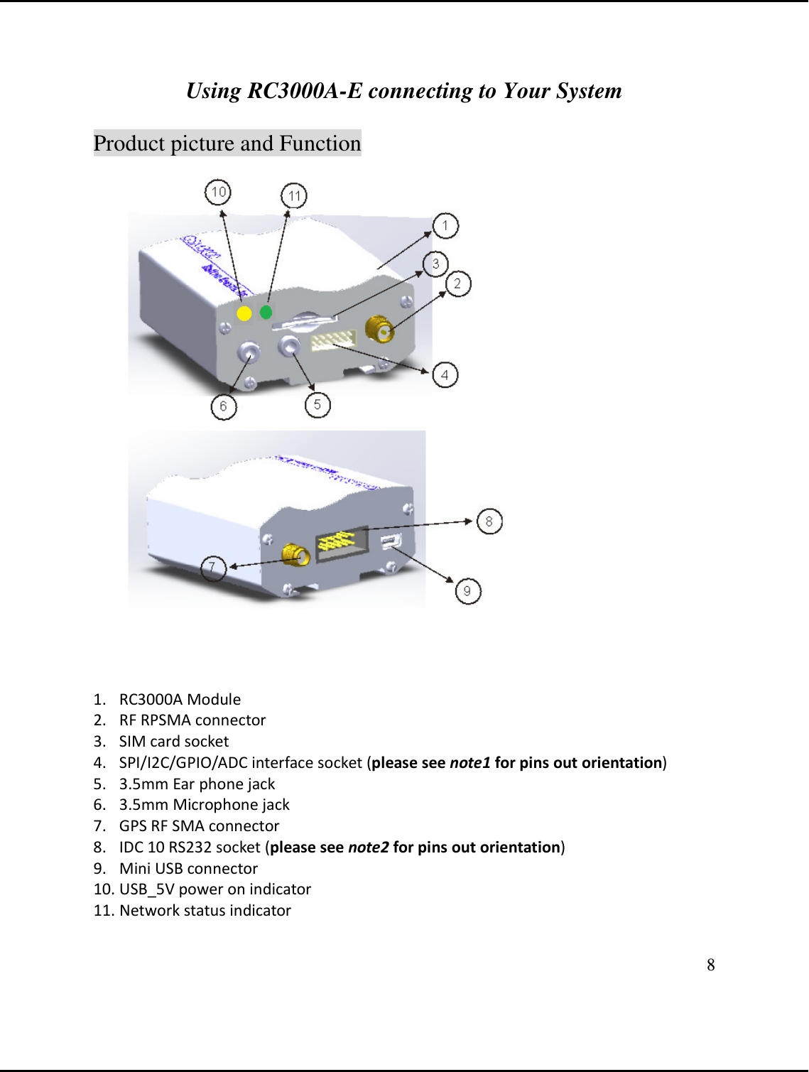
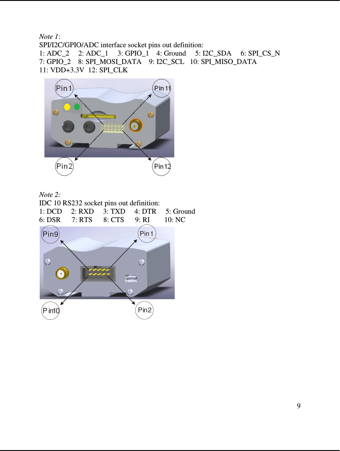
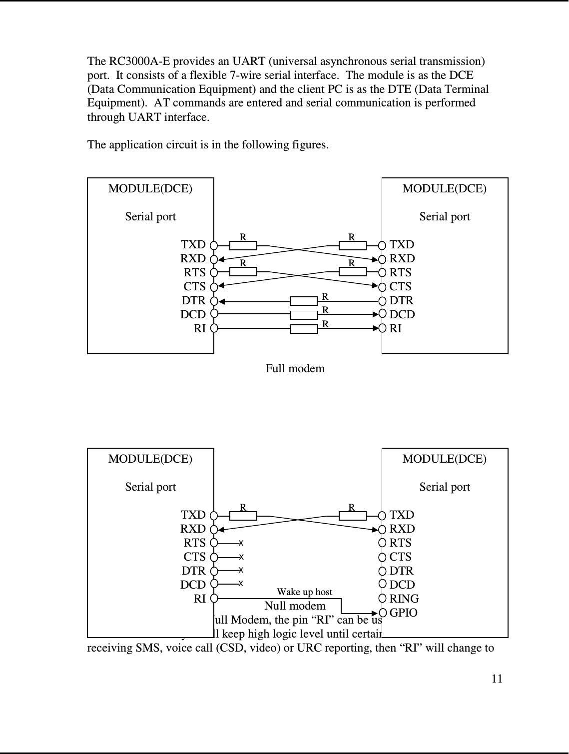
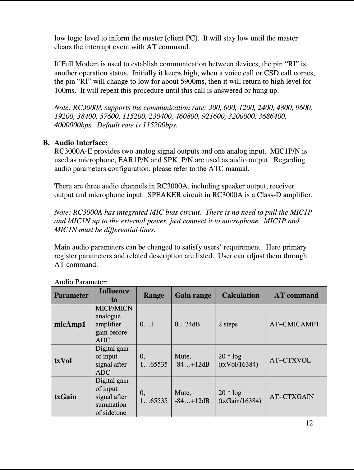
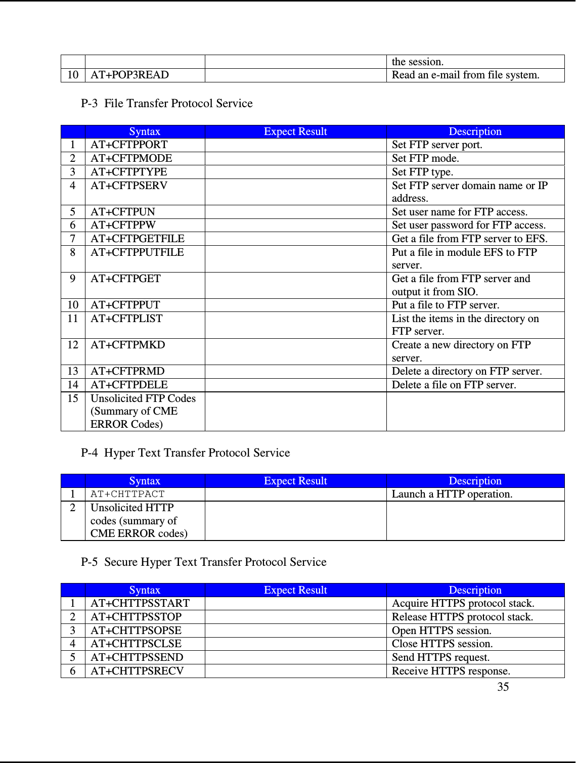
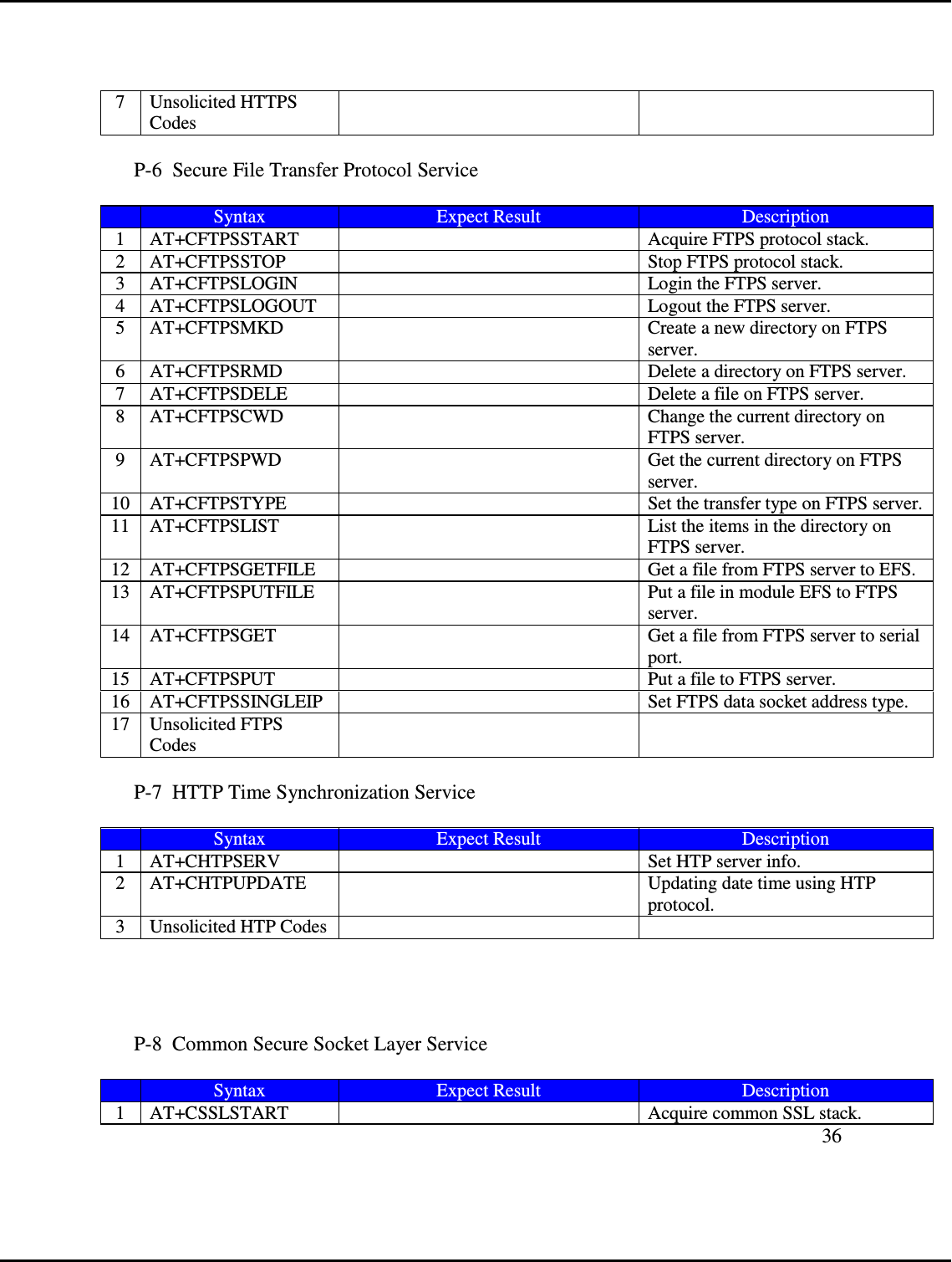
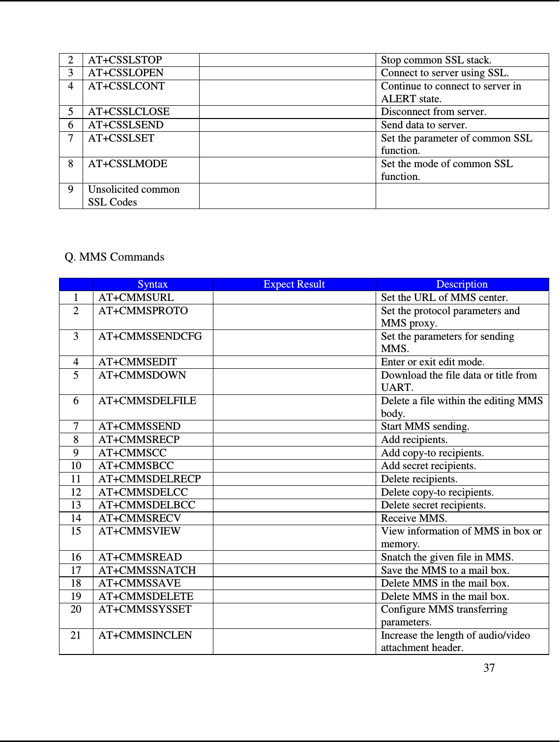
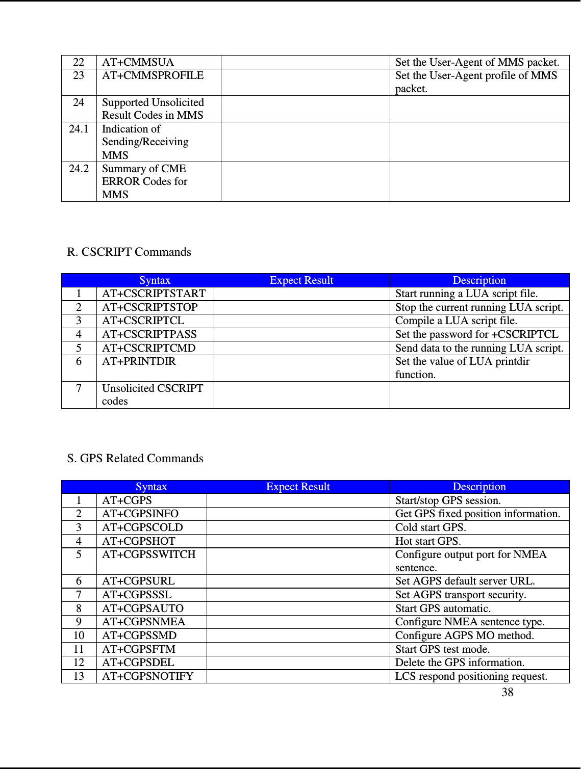
![10`Launch RC3000A-E Product 1. Connect antenna/SIM card/IDC 10 RS232 cable to ○1 RF RPSMA connector/ ○3 SIM card socket/ ○8 IDC 10 RS232 socket accordingly 2. Plug in ○9 Mini USB connector 5V power 3. ○11 USB_5V power on indicator (blue LED) will turn on 4. ○10 Network status indicator (green LED) will be on after blue LED turns on 5 seconds, RC3000AMB is entering power on sequence at this stage. 5. When Docklight screen shows below message which means the UART port is established: 6. 2014/1/3 14:51:44.068 [RX] - <NUL> ?<CR><LF> 7. START<CR><LF> 8. <CR><LF> 9. +STIN: 25<CR><LF> 10. <CR><LF> 11. +STIN: 25<CR><LF> 12. <CR><LF> 13. +CPIN: READY<CR><LF> 14. <CR><LF> 15. SMS DONE<CR><LF> 16. <CR><LF> 17. +VOICEMAIL: INIT_STATE, 0, 0<CR><LF> 18. <CR><LF> 19. PB DONE<CR><LF> 6. 3G network is connected if the ○10 Network status indicator (green LED) flashed once/sec 7. Type AT command to control RC3000AMB kit (please refer to page 36 AT Commands Samples) 8. Dial SIM card phone number, and type “A” “T” “A” to pick up phone call <CR><LF> RING<CR><LF> 2014/1/3 15:27:11.249 [TX] - A 2014/1/3 15:27:11.258 [RX] - A 2014/1/3 15:27:11.718 [TX] - T 2014/1/3 15:27:11.728 [RX] - T 2014/1/3 15:27:12.178 [TX] - A 2014/1/3 15:27:12.188 [RX] - A 2014/1/3 15:27:12.959 [TX] - <CR><LF> 2014/1/3 15:27:12.968 [RX] - <CR> <CR><LF> VOICE CALL: BEGIN<CR><LF> <CR><LF> OK<CR><LF> Hardware Interface A. UART interface:](https://usermanual.wiki/Radicom-Research/RC3000A/User-Guide-2645885-Page-10.png)