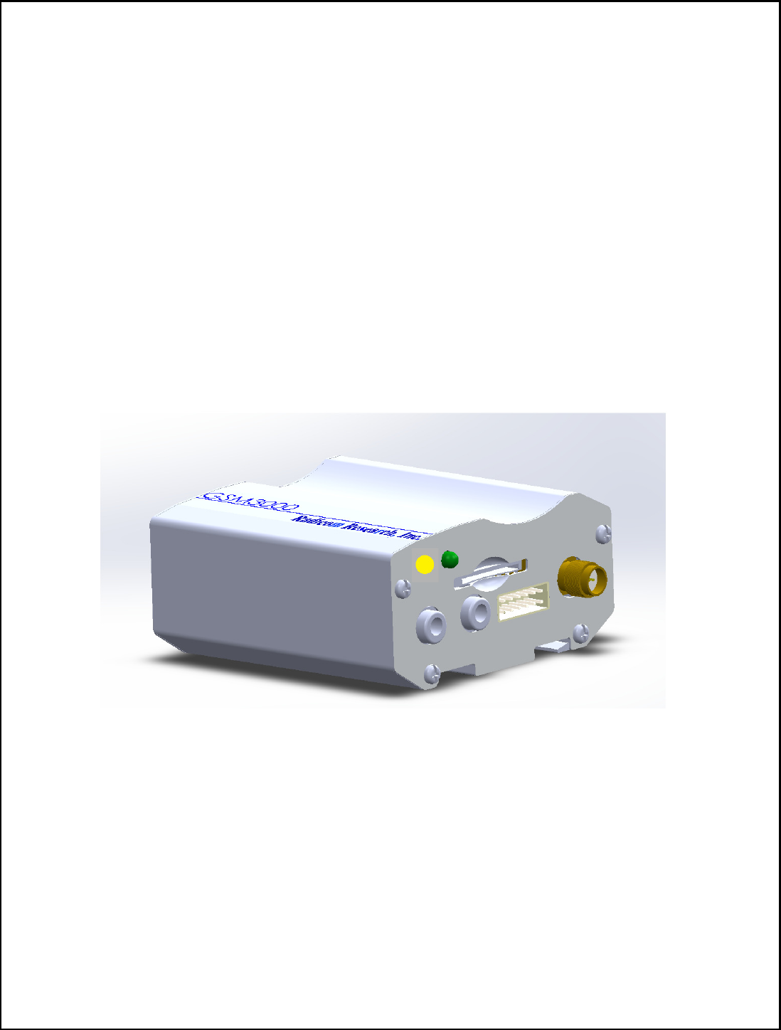
Radicom Research RC3000A Cellular Modem User Manual RC3000A E v1 5
Radicom Research Inc Cellular Modem RC3000A E v1 5
Users Manual
1
Radicom Research, Inc.
Preliminary
User Manual
for the
RC3000A-E

2
Table of Contents
RC3000A-E Product Introduction 3
RC3000A-E Functional Architecture 4
RC3000A-E module Features 5
RC3000A-E Product Mechanical Dimensions 7
Using RC3000AMB to connect to Your System 8
Hardware interface 11
A. UART interface 11
B. Audio interface 12
C. USB interface 13
D. I2C interface 14
E. SPI interface 14
F. GPIO interface 14
G. PCM interface 14
H. ADC interface 15
Global Positioning System (GPS) 16
Federal Communication Commission Interference Statement
18
Industry Canada statement 19
Safety Rules and Recommendations
20
Antenna Requirements 21
SIM Card Information
23
Introduction to Modem Operation – The AT Command Set 24
Limited Warranty 41
Contacting Radicom Research 43
Information furnished by Radicom Research is believed to be accurate and reliable. However
Radicom Research assumes no responsibility for its use, or any infringement of patents or other
rights of third parties that may result from its use. Radicom Research reserves the right to
change circuitry at any time without notice. This document is subject to change without notice.
3
RC3000A-E Product Introduction
Thank you for purchasing Radicom Research’s RC3000A-E product. We are committed
to providing you quality service and technical support. The RC3000A-E is the perfect
solution for integrating WCDMA applications into many different types of embedded
hosts or remote equipment. This product is fully self-contained and requires only a serial
TTL interface from your product, SIM card and cellular signal access to provide you with
state of the art data, fax, and voice operation.
Designed for the global marketplace, RC3000A-E is a quad-band GSM/GPRS/EDGE and
dual-band UMTS/HSDPA that works on frequencies of GSM 850MHz, EGSM 900MHz,
DCS 1800MHz, PCS 1900MHz and WCDMA 2100/900MHz, 2100/850MHz or
1900/850MHz. User can choose the module based on the wireless network configuration.
The entire radio band configuration of RC3000A-E is described in the following table.
Standard Frequency RC3000A
GSM
GSM 850MHz
EGSM 900MHz
DCS 1800MHz
PCS 1900MHz
WCDMA
WCDMA 850MHz
WCDMA 900MHz
WCDMA 1900MHz
WCDMA 2100MHz
HSPA HSDPA
HSUPA
This document is a guideline to help you design the RC3000A-E into your system. If
further information is needed please contact Radicom and we will provide any additional
help you may need.
4
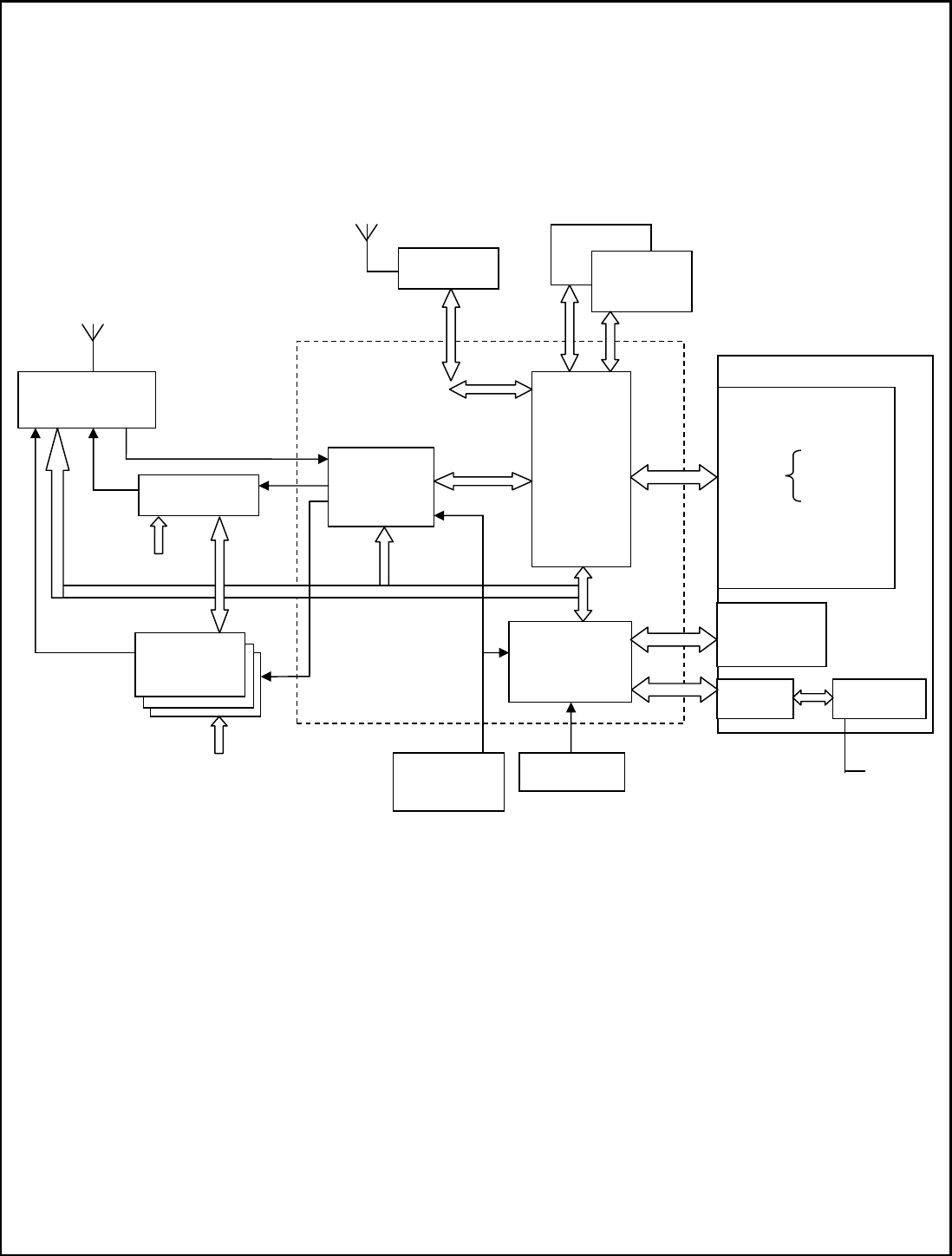
RC3000A-E Functional Architecture
Transceiver
Processor
Power
Management
32.768kHz
VCTCXO
19.2MHz
GPS RF
DDR
NAND
Flash
GSM PA
GSM/WCDMA
RF Frontend
WCDMA
PA
SIM
UART
Audio
I2C
USB
GPIOs
ADC
LDO
SPI
Power On
Reset
Vbat*
PCM
Interrupt
Status LED
Vbat*
Single Chip
WCDMA/GSM
Antenna
Vbat*
Regulator
Mini USB
connector
GPS Antenna

5
RC3000A-E Features
• RC3000A: Dual-Band UMTS/HSDPA 850/1900MHz, Quad-Band
GSM/GPRS/EDGE 850/900/1800/1900MHz
• Supported embedded LUA Script Language
• A-GPS: MS-Based, MS-Assisted supported
• Support for Data transfer:
HSDPA: Max. 3.6Mbps(DL)
WCDMA: Max. 384Kbps(DL), Max. 384Kbps(UL)
EDGE Class: Max. 236.8Kbps(DL), Max. 118Kbps(UL)
GPRS: Max. 85.6Kbps(DL), Max. 42.8Kbps(UL)
CSD:
• GSM data rate 14.4Kbps
• WCDMA data rate 57.6Kbps
• WCDMA 64Kbps CSD for Video Call
• Support in GSM and WCDMA for Network Identity and Time zone (NITZ)
• MMS
• TCP/IP
• MUX protocol
• FTP/FTPS/HTTPS/SMTP/POP3/DNS
• FOTA
• eCall Ready
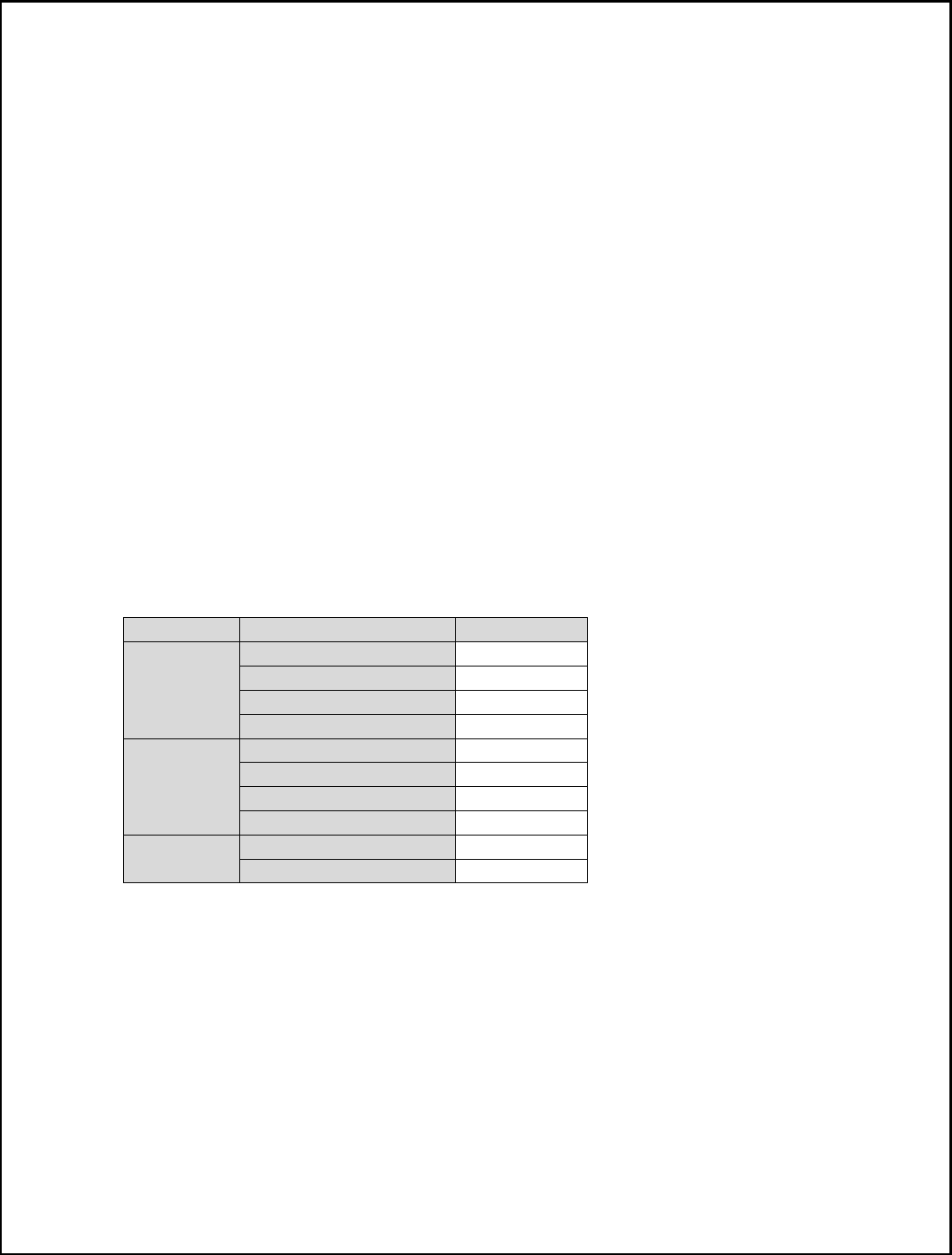
• Supported interface: USB2.0, UART, SIM card, SPI, I2C, Keypad, Constant current
sink, GPIO, RTC, ADC, PCM
Feature Implementation
Power supply Single supply voltage 5.0+ - 0.3V
Transmission data
•
Dual-mode UMTS/HSDPA/EDGE/GPRS operation
• GPRS Class B, multi-slot class 12 operation, supports
coding scheme: CS1-4
• EDGE multi-slot class 12 operation, supports coding
scheme: MSC1-9
• UMTS R99 data rates-384 kbps DL/UL
• HSDPA Category 5/6 -3.6 Mbps Category 12-1.8 Mbps
• CSD feature: 9.6, 14.4, 64 kbps UL/DL
GPS
•
Mobile-Assisted mode
• Mobile-based mode
• Standalone mode
SMS
•
MT, MO, CB, Text and PDU mode
• SMS storage: SIM card
• Support transmission of SMS alternatively over CSD or

6
GPRS. User can choose preferred mode.
Output power
•
UMTS 850/1900: 0.25W
• UMTS 900/2100: 0.25W
• GSM850/GSM900: 2W
• DCS1800/PCS1900: 1W
Audio features
(optional)
Speech codec modes:
• Half Rate (ETS 06.20)
• Full Rate (ETS 06.10)
• Enhanced Full Rate (ETS 06.50 / 06.60 / 06.80)
• AMR (WCDMA)
• AMR+QCP (GSM)
• A5/1, A5/2, and A5/3 ciphering
Serial interface
•
Serial Port standard or null modem mode on Serial Port
Interface
• Serial Port can be used to control module by sending AT
command
USB Support USB2.0 Slave mode
Phonebook
management
Support phonebook types: SM, FD, LD, RC, ON, MC
SIM application toolkit
Support SAT class 3, GSM 11.14 Release 98
Support USAT
Real Time Clock Support RTC
Timer function Programmable by AT command
Physical characteristics
Size:1.51” x 2.15”
Weight:25g
Firmware upgrade Firmware upgrade over USB interface
PCM Multiplex on GPIOs. 3 kinds of coding formats: 8 bit (υ-law or
A-law) and 16 bit (linear)
USB Driver support
•
Microsoft Windows 2000/XP/Vista
• Windows CE/Mobile
• Linux 2.6
Temperature range
• Normal operation temperature: -30 to +80
• Storage temperature: -40 to +90
Certification
•
RC3000A-A: FCC, PTCRB
• RC3000A-E: CE, GCF
• RC3000A-J: Telec, JATE
7
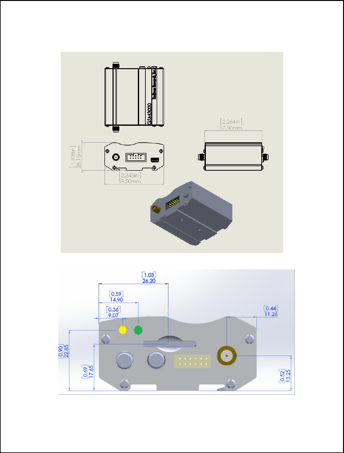
RC3000A-E Mechanical Dimensions
RC3000A-E view:
Side View:
8
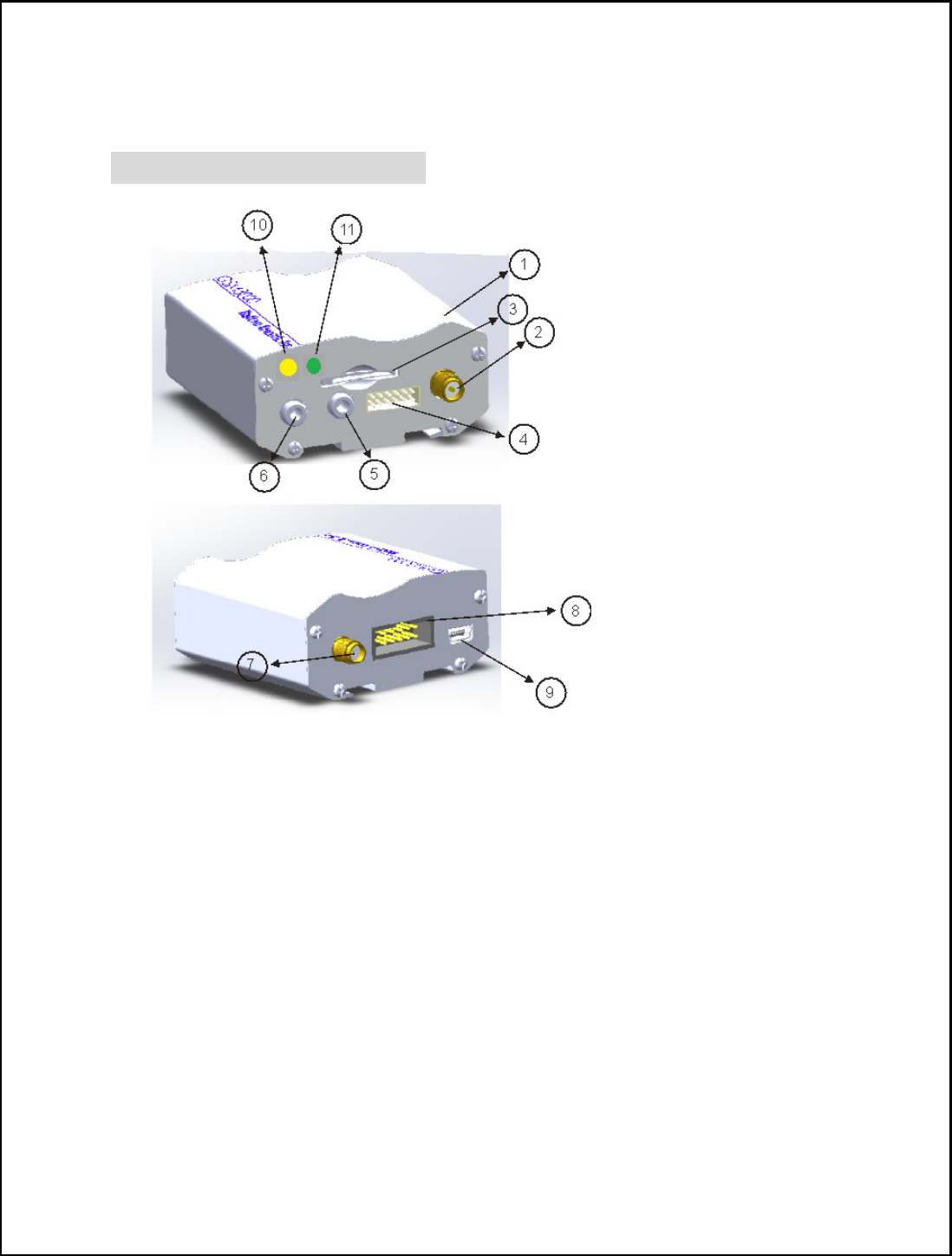
Using RC3000A-E connecting to Your System
Product picture and Function
1. RC3000A Module
2. RF RPSMA connector
3. SIM card socket
4. SPI/I2C/GPIO/ADC interface socket (please see note1 for pins out orientation)
5. 3.5mm Ear phone jack
6. 3.5mm Microphone jack
7. GPS RF SMA connector
8. IDC 10 RS232 socket (please see note2 for pins out orientation)
9. Mini USB connector
10. USB_5V power on indicator
11. Network status indicator
9
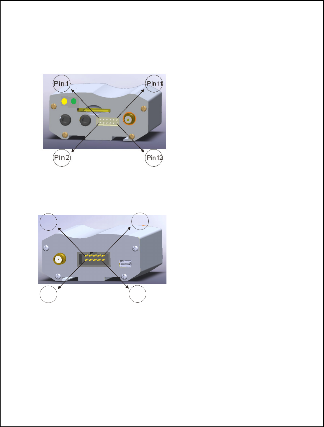
Note 1:
SPI/I2C/GPIO/ADC interface socket pins out definition:
1: ADC_2 2: ADC_1 3: GPIO_1 4: Ground 5: I2C_SDA 6: SPI_CS_N
7: GPIO_2 8: SPI_MOSI_DATA 9: I2C_SCL 10: SPI_MISO_DATA
11: VDD+3.3V 12: SPI_CLK
Note 2:
IDC 10 RS232 socket pins out definition:
1: DCD 2: RXD 3: TXD 4: DTR 5: Ground
6: DSR 7: RTS 8: CTS 9: RI 10: NC
P in10
Pin9
P in 1
P in 2

10
`Launch RC3000A-E Product
1.
Connect antenna/SIM card/IDC 10 RS232 cable to
○
1 RF RPSMA connector/
○
3 SIM card socket/
○
8 IDC 10 RS232 socket accordingly
2.
Plug in
○
9 Mini USB connector 5V power
3.
○
11 USB_5V power on indicator (blue LED) will turn on
4.
○
10 Network status indicator (green LED) will be on after blue LED turns on 5
seconds, RC3000AMB is entering power on sequence at this stage.
5.
When Docklight screen shows below message which means the UART port is
established:
6. 2014/1/3 14:51:44.068 [RX] - <NUL> ?<CR><LF>
7. START<CR><LF>
8. <CR><LF>
9. +STIN: 25<CR><LF>
10. <CR><LF>
11. +STIN: 25<CR><LF>
12. <CR><LF>
13. +CPIN: READY<CR><LF>
14. <CR><LF>
15. SMS DONE<CR><LF>
16. <CR><LF>
17. +VOICEMAIL: INIT_STATE, 0, 0<CR><LF>
18. <CR><LF>
19. PB DONE<CR><LF>
6. 3G network is connected if the
○
10 Network status indicator (green LED) flashed
once/sec
7. Type AT command to control RC3000AMB kit (please refer to page 36 AT Commands
Samples)
8. Dial SIM card phone number, and type “A” “T” “A” to pick up phone call
<CR><LF>
RING<CR><LF>
2014/1/3 15:27:11.249 [TX] - A
2014/1/3 15:27:11.258 [RX] - A
2014/1/3 15:27:11.718 [TX] - T
2014/1/3 15:27:11.728 [RX] - T
2014/1/3 15:27:12.178 [TX] - A
2014/1/3 15:27:12.188 [RX] - A
2014/1/3 15:27:12.959 [TX] - <CR><LF>
2014/1/3 15:27:12.968 [RX] - <CR>
<CR><LF>
VOICE CALL: BEGIN<CR><LF>
<CR><LF>
OK<CR><LF>
Hardware Interface
A. UART interface:
11
The RC3000A-E provides an UART (universal asynchronous serial transmission)
port. It consists of a flexible 7-wire serial interface. The module is as the DCE
(Data Communication Equipment) and the client PC is as the DTE (Data Terminal
Equipment). AT commands are entered and serial communication is performed
through UART interface.
The application circuit is in the following figures.
Full modem
Null modem
If UART port is used in Null Modem, the pin “RI” can be used as an interrupt signal
to HOST. Normally it will keep high logic level until certain condition such as
receiving SMS, voice call (CSD, video) or URC reporting, then “RI” will change to
MODULE(DCE)
Serial port
TXD
RXD
RTS
CTS
DTR
DCD
RI
MODULE(DCE)
Serial port
TXD
RXD
RTS
CTS
DTR
DCD
RI
R R
R R
R
R
R
MODULE(DCE)
Serial port
TXD
RXD
RTS
CTS
DTR
DCD
RI
MODULE(DCE)
Serial port
TXD
RXD
RTS
CTS
DTR
DCD
RING
GPIO
R R
Wake up host
X
X
X
X

12
low logic level to inform the master (client PC). It will stay low until the master
clears the interrupt event with AT command.
If Full Modem is used to establish communication between devices, the pin “RI” is
another operation status. Initially it keeps high, when a voice call or CSD call comes,
the pin “RI” will change to low for about 5900ms, then it will return to high level for
100ms. It will repeat this procedure until this call is answered or hung up.
Note: RC3000A supports the communication rate: 300, 600, 1200, 2400, 4800, 9600,
19200, 38400, 57600, 115200, 230400, 460800, 921600, 3200000, 3686400,
4000000bps. Default rate is 115200bps.
B. Audio Interface:
RC3000A-E provides two analog signal outputs and one analog input. MIC1P/N is
used as microphone, EAR1P/N and SPK_P/N are used as audio output. Regarding
audio parameters configuration, please refer to the ATC manual.
There are three audio channels in RC3000A, including speaker output, receiver
output and microphone input. SPEAKER circuit in RC3000A is a Class-D amplifier.
Note: RC3000A has integrated MIC bias circuit. There is no need to pull the MIC1P
and MIC1N up to the external power, just connect it to microphone. MIC1P and
MIC1N must be differential lines.
Main audio parameters can be changed to satisfy users’ requirement. Here primary
register parameters and related description are listed. User can adjust them through
AT command.
Audio Parameter:
Parameter
Influence
to Range Gain range
Calculation AT command
micAmp1
MICP/MICN
analogue
amplifier
gain before
ADC
0…1 0…24dB 2 steps AT+CMICAMP1
txVol
D
igital gain
of input
signal after
ADC
0,
1…65535
Mute,
-84…+12dB
20 * log
(txVol/16384) AT+CTXVOL
txGain
D
igital gain
of input
signal after
summation
of sidetone
0,
1…65535
Mute,
-84…+12dB
20 * log
(txGain/16384)
AT+CTXGAIN

13
txFilter
I
nput PCM
13-tap filter
parameters, 7
values
0…65535
--- MATLAB
calculate AT+CTXFTR
rxGain
D
igital gain
of output
signal after
summation
of sidetone
0,
1…65535
Mute,
-84…+12dB
20 * log
(rxGain/16384)
AT+CRXGAIN
rxVol
D
igital
Volume of
output signal
after speech
decoder,
before
summation
of sidetone
and DAC
-
300…300
dbm -300…300dbm
AT+CLVL
AT+CVLVL
AT+CRXVOL
stGain
D
igital
attenuation
of sidetone
0,
1…65535
Mute,
-96…0dB
20 * log
(stGain/16384)-
12
AT+SIDET
rxFilter
O
utput PCM
13-tap filter
parameters, 7
values
0…65535
--- MATLAB
calculate AT+CRXFTR
Note: If users require better experience on audio, users should modify these
parameters according to their own electronic and mechanical design.
C. USB Interface:
RC3000A-E module contains an USB interface. This interface is compliant with the
USB2.0 specification. The USB2.0 specification requires hosts such as the computer
to support all three USB speeds, namely low-speed (1.5Mbps), full-speed (12Mbps)
and high-speed (480Mbps). USB charging and USB-OTG is not supported.
Currently RC3000A supports the USB suspend and resume mechanism which can
help to save power. If not transaction is on USB bus, RC3000A will enter suspend
mode. When some events such as voice call or receiving SMS happen, RC3000A
will resume normal mode automatically.
Note: The RC3000A has two kinds of interface (UART and USB) to connect to host
CPU. USB interface is mapped to five virtual ports: “SIMTECH USB Modem”,
“SIMTECH NMEA Device”, “SIMTECH ATCOM Device”, “SIMTECH Diagnostics
interface” and “SIMTECH Wireless Ethernet Adapter”.

14
D. I2C Interface:
I2C is used to communicate with peripheral equipment and can be operated as either
a transmitter or receiver, depending on the device function. Use AT Commands
“AT+CRIIC and AT+CWIIC” to read/write register values of related peripheral
equipment connected with I2C interface.
Both SDA and SCL are bidirectional lines, connected to a positive supply via a pull-
up resistor respectively. When the bus is free, both lines are high.
For RC3000A, the data on the I2C bus can be transferred at rates up to 400kbps. The
number of peripheral devices connected to the bus is solely dependent on the bus
capacitance limit of 400pF. Note that PCB traces length and bending are in users’
control to minimize load capacitance.
Note:I2C_SDA and I2C_SCL have been pulled up with two 2.2kR resistors to 2.6V
level in module. So there is no need to pull them up in users’ application circuit.
E. SPI Interface:
SPI interface of RC3000A is master only. It provides a duplex, synchronous, serial
communication link with peripheral devices. Its operation voltage is 1.8V, with
clock rates up to 26 MHz.
F. GPIO Interface:
RC3000A provides a limited number of GPIO pins. All GPIOs can be configured as
inputs or ouputs. User can use AT Commands to read or write GPIOs status.
Note-1: If more GPIOs need to be used, users can configure GPIO on other multiple
function interfaces, such as PCM.
Note-2: The output driver current of GPIOs is 2mA.
G. PCM Interface:
RC3000A provides hardware PCM interface for external codec. The PCM interface
enables communication with an external codec to support hands-free applications.
RC3000A PCM interface can be used in two modes: the default mode is auxiliary
PCM (8 KHz long sync mode at 128 KHz PCM CLK). In short-sync (primary PCM)
mode, RC3000A can be a master or a slave. In long-sync (auxiliary PCM) mode,
RC3000A is always a master. RC3000A also supports 3 kinds of coding formats: 8
bits (υ-law or A-law) and 16 bits (linear).
Note: PCM interface is multiplexed from GPIO (default setting). The AT command
“AT+CPCM” is used to switch between PCM and GPIO functions.
ADC Interface:
RC3000A has a dedicated ADC that is available for digitizing analog signals such as
battery voltage and so on; it is on PIN 35 and PIN 36, namely ADC1 and ADC2.
15
This ADC is 12 bit successive-approximation circuit, and electronic specification is
shown in the following table.
Electronic Characteristics:
Specification Min
Typ
Max
Unit
Comments/Conditions
Resolution 12 Bits
Differential nonlinearity
-4 +4 LSB
Analog Vdd = ADC
reference 2.4MHz sample
rate
Integral nonlinearity -8 +8 LSB
Gain Error -2.5 +2.5
%
Offset Error -4 +40 LSB
Input Range GND
4.4V
V
Input serial resistance 2 kΩ Sample and hold switch
resistance
Input capacitance 53 pF
Power-down to wakeup 9.6 19.2
µs
User can introduces a signal in the ADC pin directly and use the AT command
“AT+CADC” to get the raw data which is between 0 and 4095. The data can be
transformed to any type such as voltage, temperature, etc.

16
Global Positioning System (GPS)
RC3000A merges GPS satellite and network information to provide a high-availability
solution that offers industry-leading accuracy and performance. This solution performs
well, even in very challenging environment conditions where conventional GPS receivers
fail, and provides a platform to enable wireless operators to address both location-based
services and emergency mandates.
Technical specification:
Tracking sensitivity -157dBm
Cold-start sensitivity -144dBm
Accuracy (Open Sky) <2m (CEP50)
TTFF (Open Sky) Hot start <1s Cold start 35s (good signal)/100s (weak signal)
Receiver Type 16-channel, GPS L1 Frequency (1575.42MHz), C/A Code
Update rate default 1 Hz
GPS data format NMEA-0183
GPS Current consumption (WCDMA/GSM Sleep mode) 100mA (Total supply current)
GPS antenna Passive/Active antenna
Note: Performance will vary depending on the environment, antenna type and signal conditions
and so on.
RC3000A supports both A-GPS and S-GPS, and then provides three operating modes: mobile-
assisted mode, mobile-based mode and standalone mode. A-GPS includes mobile-assisted and
mobile-based mode.
In mobile-assisted mode, when a request for position location is issued, available network
information is provided to the location server (e.g. Cell-ID) and assistance is requested from the
location server. The location server sends the assistance information to the handset. The
handset/mobile unit measures the GPS observables and provides the GPS measurements along
with available network data (that is appropriate for the given air interface technology) to the
location server. The location server then calculates the position location and returns results to
the requesting entity.
In mobile-based mode, the assistant data provided by the location server encompasses not only
the information required to assist the handset in measuring the satellite signals, but also the
information required to calculate the handset’s position. Therefore, rather than provide the GPS
measurements and available network data back to the location server, the mobile calculates the
location on the handset and passes the result to the requesting entity.
In standalone (autonomous) mode, the handset demodulates the data directly from the GPS
satellites. This mode has some reduced cold-start sensitivity, and a longer time to first fix as

17
compared to the assisted modes. However, it requires no server interaction and works out of
network coverage.
This combination of GPS measurements and available network information provides:
• High-sensitivity solution that works in all terrains: Indoor, outdoor, urban, and rural
• High availability that is enabled by using both satellite and network information
Therefore, while network solutions typically perform poorly in rural areas and areas of poor cell
geometry/density, and while unassisted, GPS-only solutions typically perform poorly indoors.
The RC3000A GPS solution provides optimal time to fix, accuracy, sensitivity, availability, and
reduced network utilization in both of these environments, depending on the given condition.

18
Federal Communication Commission Interference Statement
This equipment has been tested and found to comply with the limits for a
Class B digital device, pursuant to Part 15 of the FCC Rules. These limits
are designed to provide reasonable protection against harmful
interference in a residential installation. This equipment generates, uses
and can radiate radio frequency energy and, if not installed and used in
accordance with the instructions, may cause harmful interference to radio
communications. However, there is no guarantee that interference will not
occur in a particular installation. If this equipment does cause harmful
interference to radio or television reception, which can be determined by
turning the equipment off and on, the user is encouraged to try to correct
the interference by one of the following measures:
- Reorient or relocate the receiving antenna.
- Increase the separation between the equipment and receiver.
- Connect the equipment into an outlet on a circuit different from that
to which the receiver is connected.
- Consult the dealer or an experienced radio/TV technician for help.
FCC Caution: Any changes or modifications not expressly approved by
the party responsible for compliance could void the user's authority to
operate this equipment.
This device complies with Part 15 of the FCC Rules. Operation is subject
to the following two conditions: (1) This device may not cause harmful
interference, and (2) this device must accept any interference received,
including interference that may cause undesired operation.
IMPORTANT NOTE:
Radiation Exposure Statement:
This equipment complies with FCC radiation exposure limits set forth for an
uncontrolled environment. This equipment should be installed and operated with
minimum distance 20cm between the radiator & your body.
This transmitter must not be co-located or operating in conjunction with
any other antenna or transmitter.

19
Industry Canada statement:
This device complies with Industry Canada’s licence-exempt RSSs. Operation is
subject to the following two conditions:
(1) This device may not cause interference; and (2) This device must accept any
interference, including interference that may cause undesired operation of the
device.
Cet appareil est conforme aux CNR exemptes de licence d'Industrie Canada.
Son fonctionnement est soumis aux deux conditions suivantes:
(1) Ce dispositif ne peut causer d'interférences; et(2) Ce dispositif doit accepter
toute interférence, y compris les interférences qui peuvent causer un mauvais
fonctionnement de l'appareil.
Radiation Exposure Statement:
This equipment complies with IC radiation exposure limits set forth for an
uncontrolled environment. This equipment should be installed and operated with
minimum distance 20cm between the radiator & your body.
Déclaration d'exposition aux radiations:
Cet équipement est conforme aux limites d'exposition aux rayonnements IC
établies pour un environnement non contrôlé. Cet équipement doit être installé et
utilisé avec un minimum de 20 cm de distance entre la source de rayonnement et
votre corps.
This radio transmitter (IC: 2377A-RC3000A) has been approved by Industry
Canada to operate with the antenna types listed below with the maximum
permissible gain indicated. Antenna types not included in this list, having a gain
greater than the maximum gain indicated for that type, are strictly prohibited for
use with this device
Cet émetteur radio (IC: 2377A-RC3000A) a été approuvé par Industrie Canada
pour fonctionner avec les types d'antenne énumérés ci-dessous avec le gain
maximal admissible indiqué. Types d'antennes ne figurent pas dans cette liste,
ayant un gain supérieur au gain maximum indiqué pour ce type, sont strictement
interdits pour une utilisation avec cet appareil
Type Manufacture Gain Connector
Dipole New Premier 1.5dBi SMA

20
Safety Rules and Recommendations
READ CAREFULLY
Be sure the use of this product is allowed in the country. It is responsibility of the user to
enforce the country regulation and the specific environment regulation. The product has
to supply a stabilized voltage source and the wiring may have to conform to local security
and fire prevention regulations.
.
The use of this product may be dangerous and has to avoid in the following areas:
• Where it can interfere with other electronic devices in environment such as
hospitals, airports, aircrafts, etc.
• Where there is risk of explosion such as gasoline stations, oil refineries, etc.
Do not disassemble the product; any mark of tampering will compromise the warranty
validity.
The product has to be handled with care, avoiding any contact with the pins because
electrostatic discharges may damage the product itself. The same cautions have to be
taken for the SIM card, checking carefully the instruction for its use. Do not insert or
remove the SIM when the product is in power saving mode.
The system integrator is responsible of the functioning of the final product; therefore,
care has to be taken to the external components of the module, as well as of any project
or installation issue, because the risk of disturbing the GSM network or external devices
or having impact on the security. Should there be any doubt, please refer to the technical
documentation and the regulations in force.
21
Antenna Requirements
Every module has to be equipped with a proper antenna with specific characteristics.
The antenna for RC3000A must meet the following requirements:
This device is to be used only for mobile and fixed application. End-users must be
provided with transmitter operation conditions for satisfying RF exposure compliance.
OEM integrators must ensure that the end user has no manual instructions to remove or
install RC3000A modem. Antennas used for this OEM module must not exceed 3dBi
gain for mobile and fixed operating configurations.
GSM Antenna – Installation Guidelines
• Install the antenna in a place covered by the GSM signal. The Antenna must be
installed to provide a separation distance of at least 20 cm from all persons and
must not be co-located or operated in conjunction with any other antenna or
transmitter. In case of this requirement cannot be satisfied, the system integrator
has to assess the final product against the SAR regulation.
• Due to the RC3000A antenna characteristics to environmental sensitivity, the
antennas location should consider that the performance could be affected by a
building’s characteristics or other obstructions that may interfere with the
modules ability to make a strong connection to the intended cellular signal
provider.
ANTENNA REQUIREMENTS
Frequency Range Depending by frequency band(s) provided by the
network operator, the customer must use the most
suitable antenna for that/those band(s).
Bandwidth 80 MHz in EGSM 900, 70 MHz if GSM 850, 170
MHz in DCS, 140 MHz PCS band
Gain Gain < 1.5dBi
Impedance 50 ohm
Input Power > 2 W peak power
VSWR Absolute max <= 10:1
VSWR Recommend <= 2:1
WARNING:
Using an antenna other than the type approved for
use with this product requires the finished product, with the module
and new antenna type installed to be tested to comply with all
sections of FCC Part 15 requirements!

22
• The Antenna must not be co-located or operated in conjunction with any other
antenna or transmitter.
• Antenna shall not be installed inside metal cases.
•
Antenna shall be installed also according Antenna manufacturer instructions.

23
SIM (Subscriber Identity Module) Card Information
To access a cellular network you must purchase a compatible SIM card. The GSM
modules have a SIM card slot located on the bottom of the PCB. The SIM card has to be
handled with care, avoiding any contact with the pins because electrostatic discharges
may damage the product itself. Please read the SIM manufactures instructions prior to
installing.
Do not insert or remove the SIM card when the product is in power saving mode.
The SIM interface complies with the GSM Phase 1 specification as well as GSM Phase
2+ specification for FAST 64 kbps SIM card. The module supports both 1.8Volt and 3
Volt SIM cards. The SIM card is enabled with the AT+CSDT command.

24
Introduction to Modem Operation-The AT Command Set
RC3000A modules are used to originate or answer telephone calls and establish links
with other devices for the purpose of transmitting voice, data, or fax information between
two locations. Please refer to the SIM900 AT Command Manual for complete AT
command listings and information
After installation, you will now be able to communicate with the modem and establish
connections with remote devices. Controlling the modem functions is accomplished by
using “AT” commands. These commands are used to instruct the modem to perform
functions such as dialing or to answers calls. These commands are normally
automatically issued by communication software. However for some applications,
custom software may have to be written due to the absence of a normal operating system
such as DOS or Windows.
NOTE: The first AT command issued must be Upper Case AT. Subsequent AT
commands can be either Upper Case or Lower Case.
The modem will automatically accept and process “AT” commands at most standard
DTE (Data Terminal Equipment) speeds and parity settings. For each command issued,
the modem will respond with a result code informing you of the modem’s status. The
format of a basic “AT” command and result code is as follows:
AT <Command> <CR>
OK
AT = ATtention what follows is a command
<Command> = any valid command
<CR> = Carriage Return or Enter Key
OK = Result code meaning: the modem has accepted the command
AT Commands Samples
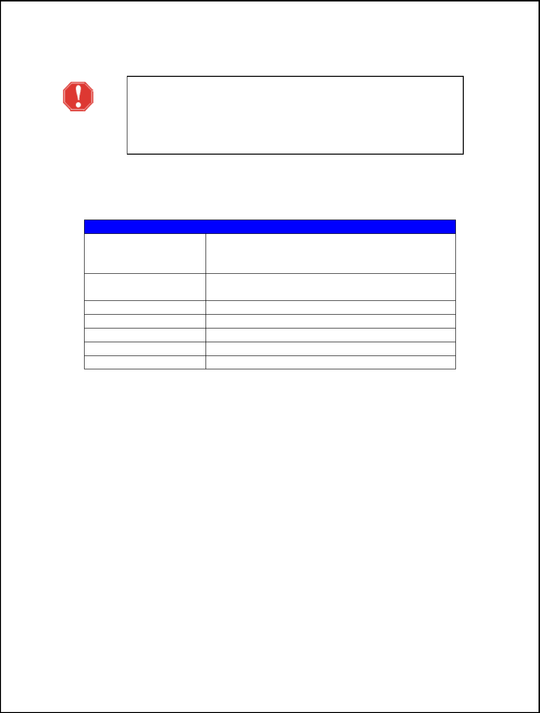
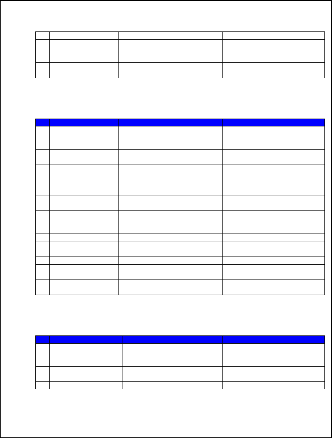
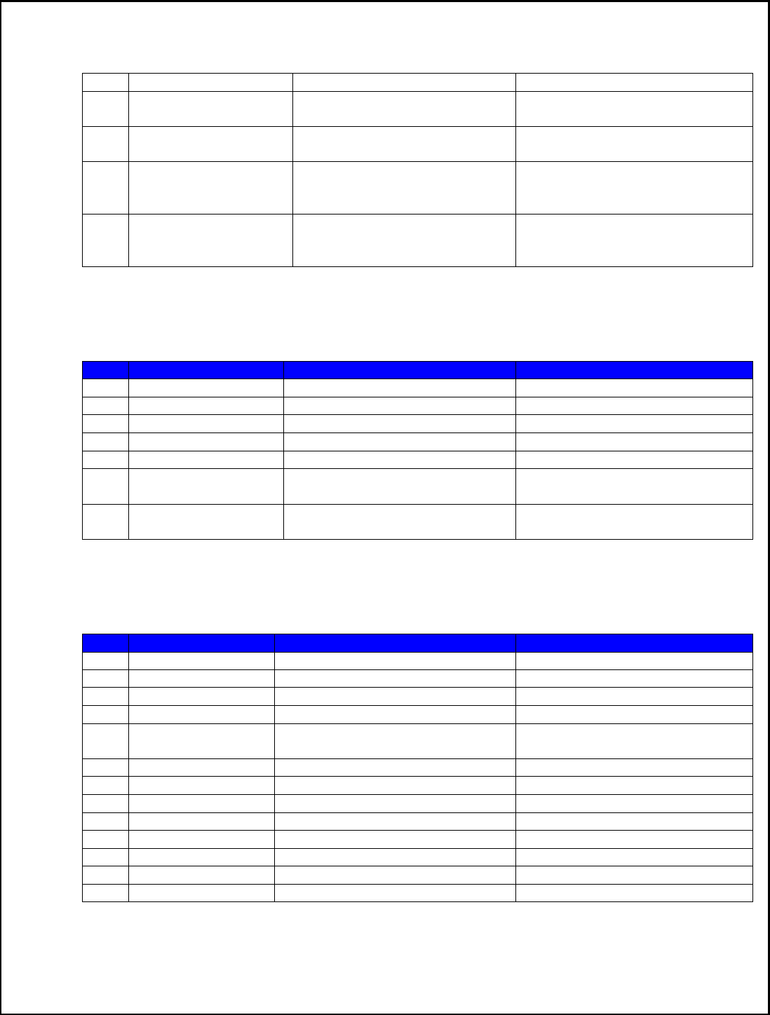
A. General Commands
Syntax
Expect Result
Descrip
tion
1
ATI
Display product identification
information.
2
AT+CGMI
Request manufacturer identification.
3
AT+CGMM
Request model identification.
4
AT+CGMR
Request revision identification.
5
AT+CGSN
Request product serial number

25
identification.
6
AT
+CSCS
Select TE character set.
7
AT+CIMI
Request international mobile
subscriber identity.
8
AT+GCAP
Request overall capabilities.
9
AT+CATR
Configure URC destination interface.
10
A/
Repeat last command.
11
AT+CFGRI
Indicate RI when using URC.
B. Call Control Commands
Syntax
Expect Result
Description
1
AT+CSTA
Select type of address.
2
AT+CMOD
Call mode.
3
ATD
Dial command.
4
ATD><mem><n>
Originate call from specified
memory.
5
ATD><n>
Originate call from active memory
(1).
6
A
TD><str>
Originate call from active memory
(2).
7
ATA
Call answer.
8
+++
Switch from data mode to command
mode.
9
ATO
Switch from command mode to data
mode.
10
AT+CVHU
Voice hang up control.
11
ATH
Disconnect existing call.
12
AT+CHUP
Hang up
call.
13
AT+CBST
Select bearer service type.
14
AT+CRLP
Radio link protocol.
15
AT+CR
Service reporting control.
16
AT+CEER
Extended error report.
17
AT+CRC
Cellular result codes.
18
AT+VTS
DTMF and tone generation.
19
AT+CLVL
Loudspeaker vol
ume level.
20
AT+VMUTE
Speaker mute control.
21
AT+CMUT
Microphone mute control.
22
AT+AUTOANSWER
Automatic answer quickly.
23
ATS0
Automatic answer.
24
AT+CALM
Alert sound mode.
25
AT+CRSL
Ringer sound level.
26
AT+CSDVC
Switch voice channel
device.
27
AT+CPTONE
Play tone.

26
28
AT+CPCM
External PCM codec mode
configuration.
29
AT+CPCMFMT
Change the PCM format.
30
AT+CPCMREG
Control PCM data transfer by
diagnostics port.
31
AT+VTD
Tone duration.
32
AT+CODEC
Set audio codec mode.
33
AT+CVOC
Get the current vocoder capability in
a call.
C. SMS Commands
Syntax
Expect Result
Description
1
+CMS ERROR
Message service failure result code.
2
AT+CSMS
Select message service.
3
AT+CPMS
Preferred message storage.
4
AT+CMGF
Select
SMS message format.
5
AT+CSCA
SMS service centre address.
6
AT+CSCB
Select cell broadcast message
indication.
7
AT+CSDH
Show text mode parameters.
8
AT+CNMA
New message acknowledgement to
ME/TA.
9
AT+CNMI
New message indications to TE.
10
AT+CMG
L
List SMS messages from preferred
store.
11
AT+CMGR
Read message.
12
AT+CMGS
Send message.
13
AT+CMSS
Send message from storage.
14
AT+CMGW
Write message to memory.
15
AT+CMGD
Delete message.
16
AT+CSMP
Set text mode parameters.
17
AT+CMGRO
Read message only.
18
AT+CMGMT
Change message status.
19
AT+CMVP
Set message valid period.
20
AT+CMGRD
Read and delete message.
21
AT+CMGSO
Send message quickly.
22
AT+CMGWO
Write message to memory quickly.
23
AT+CMGSEX
Send message.
24
AT+CM
GENREF
Generate a new message reference.
25
AT+CMSSEX
Send multi messages from storage.
26
AT+CMSSEXM
Send message from storage to multi
DA.

27
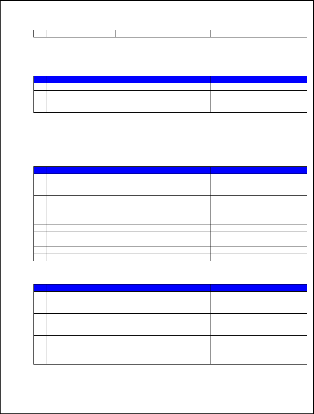
D. Network Service Related Commands
Syntax
Expect Result
Description
1
AT+CREG
Network registration.
2
AT+
COPS
Operator selection.
3
AT+
CLCK
Facility lock.
4
AT+
CPWD
Change password.
5
AT+
CLIP
Calling line identification
presentation.
6
AT+
CLIR
Calling line identification
restriction.
7
AT+
COLP
Connected line identification
presentation.
8
AT
+
CCUG
Closed user group.
9
AT+
CCFC
Call forwarding number and
conditions.
10
AT+
CCWA
Call waiting.
11
AT+
CHLD
Call related supplementary services.
12
AT+
CUSD
Unstructured supplementary service
data.
13
AT+
CAOC
Advice of charge.
14
AT+
CSSN
Supp
lementary service notifications.
15
AT+
CLCC
List current calls.
16
AT+
CPOL
Preferred operator list.
17
AT+
COPN
Read operator names.
18
AT+
CNMP
Preferred mode selection.
19
AT+
CNBP
Preferred band selection.
20
AT+
CNAOP
Acquisitions order prefere
nce.
21
AT+
CNSDP
Preferred service domain selection.
22
AT+
CPSI
Inquiring UE system information.
23
AT+
CNSMOD
Show network system mode.
24
AT+
CTZU
Automatic time and time zone
update.
25
AT+
CTZR
Time and time zone reporting.
26
AT+
CCINFO
Show c
ell system information.
27
AT+
CSCHN
Show cell channel information.
28
AT+
CSRP
Show serving cell radio parameter.
29
AT+
CRUS
Show cell set system information.
30
AT+
CPLMNWLIST
Manage PLMNs allowed by
customer.
31
AT+
CPASSMGR
Manage password.
32
A
T+
CNSVSQ
Network band scan quickly.
33
AT+
CNSVS
Network full band scan in string
format.
28
34
AT+
CNSVN
Network full band scan in numeric
format.
35
AT+
CNSVUS
Network band scan by channels in
string.
36
AT+
CNSVUN
Network band scan by channels in
numeric.
37
AT+
CCGMDF
Enable single mode in RAT
balancing mode.
38
AT+
CPLMNPASS
Manage PLMN filter password.
39
AT*CNTI
Query Network Mode.
E. Mobile Equipment Control and Status Commands
Syntax
Expect Result
Description
1
+CME ERROR
Mobile Equ
ipment error result code.
2
AT+
CMEE
Report mobile equipment error.
3
AT+
CPAS
Phone activity status.
4
AT+
CFUN
Set phone functionality.
5
AT+
CPIN
Enter PIN.
6
AT+
CSQ
Signal quality.
7
AT+
AUTOCSQ
Set CSQ report.
8
AT+
CACM
Accumulated call meter
.
9
AT+
CAMM
Accumulated call meter maximum.
10
AT+
CPUC
Price per unit and currency table.
11
AT+
CPOF
Control phone to power down.
12
AT+
CCLK
Real time clock.
13
AT+
CRFEN
RF check at initialization.
14
AT+
CRESET
Reset ME.
15
AT+
SIMEI
Set modul
e IMEI.
16
AT+
DSWITCH
Change diagnostics port mode.
17
AT+
CDELTA
Write delta package to FOTA
partition.
18
AT+
CDIPR
Set UART baud rate.
19
AT+
CUDIAG
Switch UART from AT service to
DIAG service.
20
AT+
CUDLOADS
Switch to UART download mode.
F. SIMCard Related Commands
Syntax
Expect Result
Description
1
AT+
CICCID
Read ICCID in SIM card.
2
AT+
CSIM
Generic SIM access.

29
3
AT+
CRSM
Restricted SIM access.
4
AT+
SPIC
Time remain to input SIM PIN/PUK
5
AT+
CSPN
Get service provider name from
SIM.
6
AT+
CRFSIM
Reinitialize the SIM card.
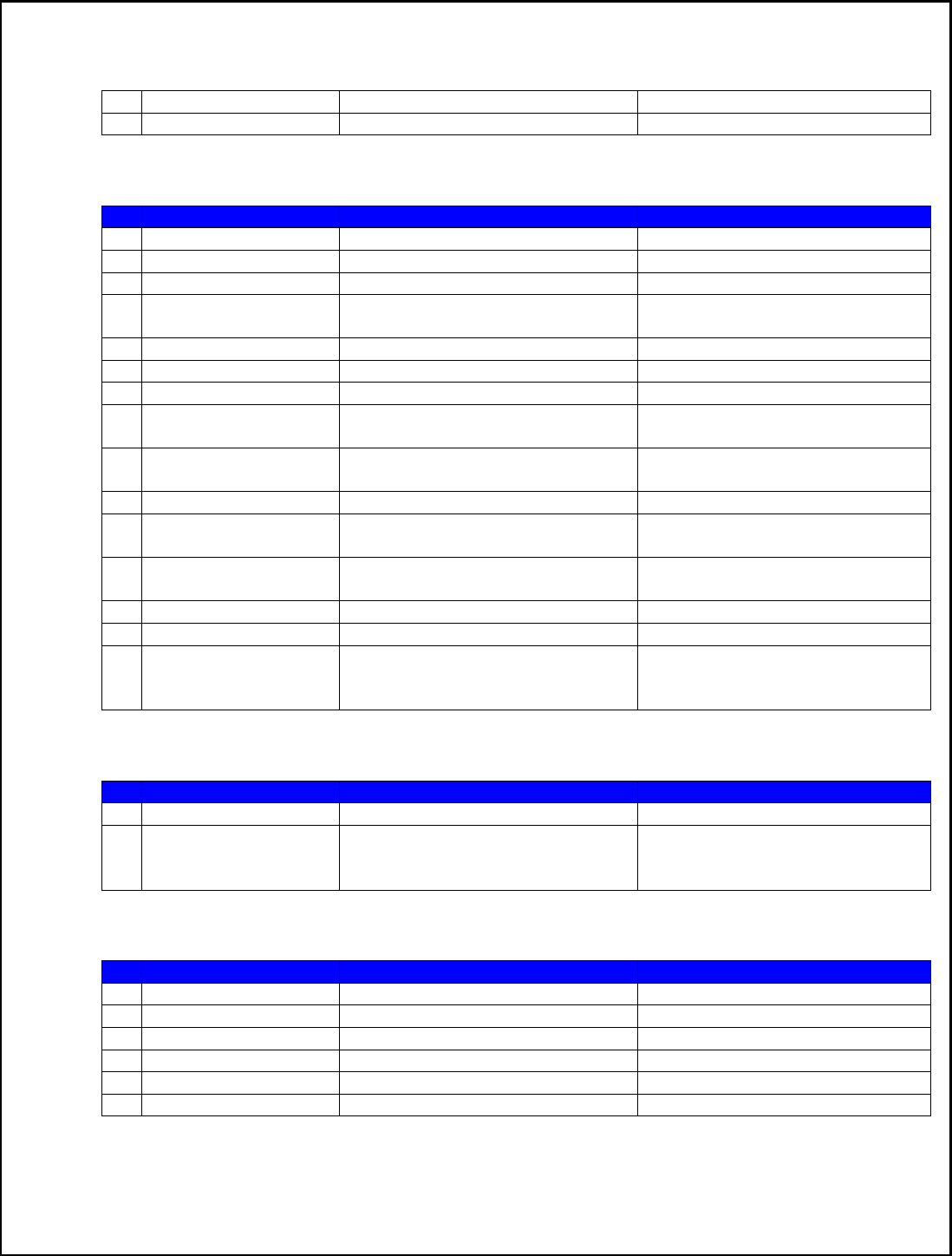
G. Hardware Related Commands
Syntax
Expect Result
Description
1
AT+
CTXGAIN
Set TX gain.
2
AT+
CRXGAIN
Set RX gain.
3
AT+
CTXVOL
Set TX volume.
4
AT+
CRXVOL
Set RX volume.
5
AT+
CTXFTR
Set TX filter.
6
AT+
CRXFTR
Set RX filter.
7
AT+
CVALARM
Low voltage Alarm.
8
AT+
CRIIC
Read values from register of IIC
device.
9
AT+
CWIIC
Write values to register of IIC
device.
10
AT+
CVAUXS
Set state of the pin named
VREG_AUX1.
11
AT+
CVAUXV
Set voltage value
of the pin named
VREG_AUX1.
12
AT+
CGPIO
Set Trigger mode of interrupt GPIO.
13
AT+
CGDRT
Set the direction of specified GPIO.
14
AT+
CGSETV
Set the value of specified GPIO.
15
AT+
CGGETV
Get the value of specified GPIO.
16
AT+
CGISR
Set interrupt tri
gger condition and
start such interruption.
17
AT+
CADC
Read ADC value.
18
AT+
CMICAMP1
Set value of micamp1.
19
AT+
CVLVL
Set value of sound level.
20
AT+
SIDET
Digital attenuation of sidetone.
21
AT+
CECM
Enable/Disable Echo Canceller.
22
AT+
CNSM
Enable/Disable Noise Suppression.
23
AT+
CECSET
Adjust the effect for the given echo
cancellation mode.
24
AT+
CRIRS
Reset RI pin of serial port.
25
AT+
CSUART
Switch UART line mode.
26
AT+
CMUX
Enable the multiplexer over the
UART.
27
AT+
CMUXSRVPORT
Configure the specific virtual com
port to the appropriate service.
30
28
AT+
CDCDMD
Set DCD pin mode.
29
AT+
CDCDVL
Set DCD pin high
-
low in GPIO
mode.
30
AT+
CBC
Battery charge.
31
AT+
CDTRISRMD
Configure the trigger condition for
DTR’s interrupt.
32
A
T+
CDTRISRS
Enable/Disable the pin of DTR’s
awakening function.
33
AT+
CGFUNC
Enable/Disable the function for the
special GPIO.
34
AT+
CGWHOST
Reset GPIO 41 to high level.
35
AT+
CGWISRMD
Configure the trigger condition for
GPIO43’s.
36
AT+
CKGSWT
Swit
ch pins’ function.
37
+
KEY
Keypad result code.
38
AT+
CUSBSPD
Switch USB high or full speed.
39
AT+
CLEDITST
Adjust the LED’s intensity.
40
AT+
CADCA
Read the value from the second
ADC.
41
AT+
CAPWRON
Auto power on setting.
42
AT+
CAPWROFF
Auto powe
r off setting.
43
AT+
CBVTBP
Set 800
-
850 band indicator.
44
AT+
CRFOP
Set the value of RF output power.
H. SPI Related Commands
Syntax
Expect Result
Description
1
AT+
CSPISETCLK
SPI clock rate setting.
2
AT+
CSPISETCS
SPI chip select setting.
3
AT+
CSPISETF
SPI clock frequency setting.
4
AT+
CSPISETPARA
SPI transfer parameters setting.
5
AT+
CSPIW
Write data to SPI.
6
AT+
CSPIR
Read data from SPI.
I. Phonebook Related Commands
Syntax
Expect Result
Description
1
AT+
CNUM
Subscriber num
ber.
2
AT+
CPBS
Select phonebook memory storage.
3
AT+
CPBR
Read phonebook entries.
4
AT+
CPBF
Find phonebook entries.
5
AT+
CPBW
Write phonebook entry.
31
6
AT+
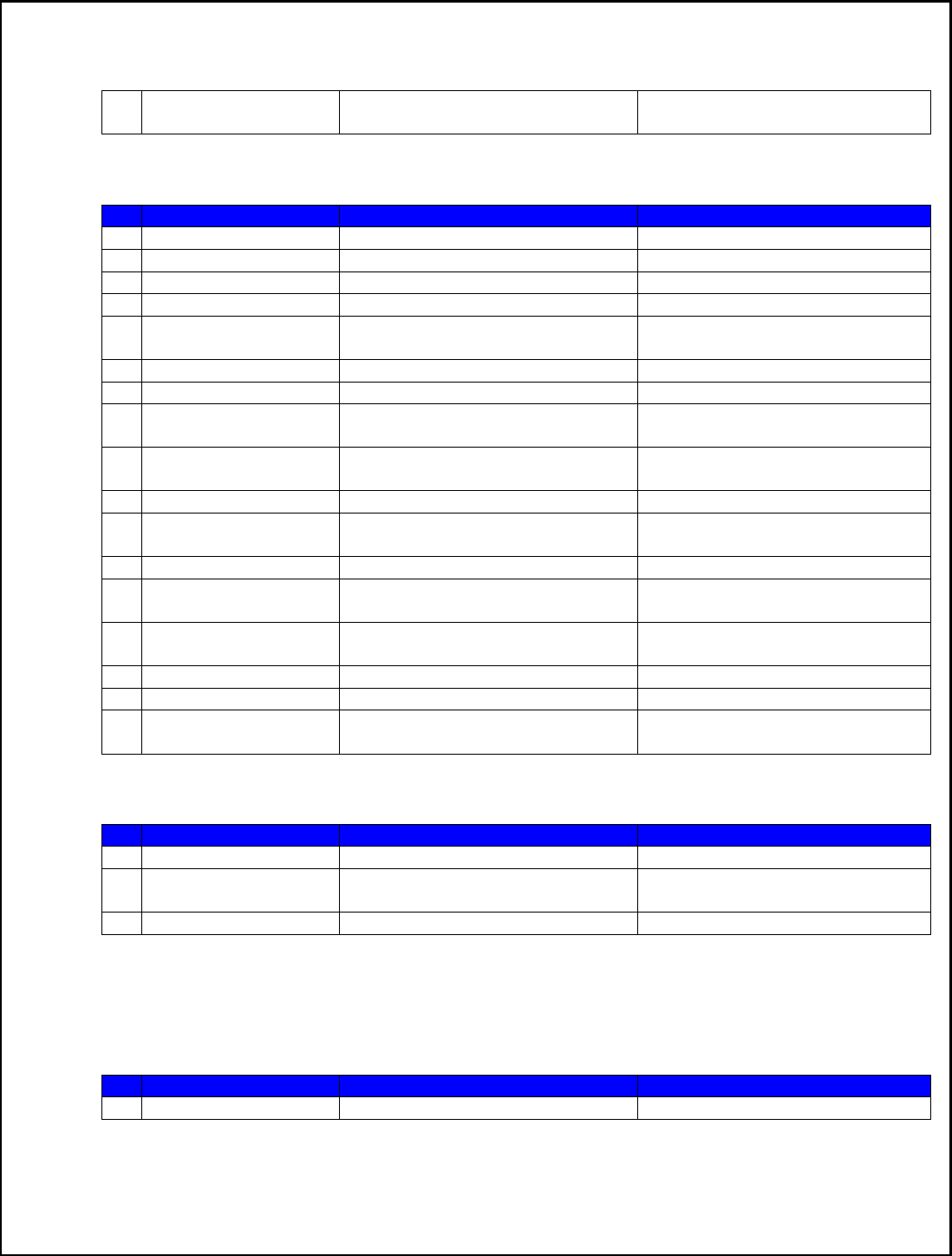
CEMNLIST
Set the list of emergency number.
J. File System Related Commands
Syntax
Exp
ect Result
Description
1
AT+
FSCD
Select directory as current directory.
2
AT+
FSMKDIR
Make new directory in current
directory.
3
AT+
FSRMDIR
Delete directory in current directory.
4
AT+
FSLS
List directories/files in current
directory.
5
AT+
FSDEL
De
lete file in current directory.
6
AT+
FSRENAME
Rename file in current directory.
7
AT+
FSATTRI
Request file attributes.
8
AT+
FSMEM
Check the size of available memory.
9
AT+
FSLOCA
Select storage place.
10
AT+
FSCOPY
Copy an appointed file.
K. File Transmission Related Commands
Syntax
Expect Result
Description
1
AT+
CTXFILE
Select file transmitted to PC host.
2
AT+
CRXFILE
Set name of file received from PC
host.
3
AT+
CMWAIT
Config the waiting seconds before
xmodem start receiving.
4
AT+
CFTR
ANRX
Transfer a file to EFS.
5
AT+
CFTRANTX
Transfer a file from EFS to external
host.
L. V24-V25 Commands
Syntax
Expect Result
Description
1
AT+
IPR
Set local baud rate temporarily.
2
AT+
IPREX
Set local baud rate permanently.
3
AT+
ICF
Set co
ntrol character framing.
4
AT+
IFC
Set local data flow control.
5
AT&C
Set DCD function mode.
6
ATE
Enable command echo.
32
7
AT&V
Display current configuration.
8
AT&D
Set DTR function mode.
9
AT&S
Set DSR function mode.
10
ATV
Set result code f
ormat mode.
11
AT&F
Set all current parameters to
manufacturer defaults.
M. Commands for Packet Domain
Syntax
Expect Result
Description
1
AT+
CGDCONT
Define PDP Context.
2
AT+
CGDSCONT
Define Secondary PDP Context.
3
AT+
CGTFT
Define Secondary
PDP Context.
4
AT+
CGQREQ
Quality of service profile
(requested).
5
AT+
CGEQREQ
3G quality of service profile
(requested).
6
AT+
CGQMIN
Quality of service profile (minimum
acceptable).
7
AT+
CGEQMIN
3G quality of service profile
(minimum acceptable).
8
AT+
CGATT
Packet domain attach or detach.
9
AT+
CGACT
PDP context activate or deactivate.
10
AT+
CGDATA
Enter data state.
11
AT+
CGPADDR
Show PDP address.
12
AT+
CGCLASS
GPRS mobile station class.
13
AT+
CGEREP
GPRS event reporting.
14
AT+
CGREG
GP
RS network registration status.
15
AT+
CGSMS
Select service for MO SMS
messages.
16
AT+
CGAUTH
Set type of authentication for PDP
-
IP connections of GPRS.
N. TCP/IP Related Commands
Syntax
Expect Result
Description
1
AT+
CGSOCKCONT
Define socket P
DP context.
2
AT+
CSOCKSETPN
Set active PDP context’s profile
number.
3
AT+
CSOCKAUTH
Set type of authentication for PDP
-
IP connections of socket.
4
AT+
CGSOCKQREQ
Quality of service profile

33
(requested).
5
AT+
CGSOCKEQREQ
3G quality of service profile
(requested).
6
AT+
CGSOCKQMIN
Quality of service profile (minimum
acceptable).
7
AT+
CGSOCKEQMIN
3G quality of service profile
(minimum acceptable).
8
AT+
IPADDR
Inquire socket PDP address.
9
AT+
NETOPEN
Open socket.
10
AT+
TCPCONNECT
Establish TCP co
nnection.
11
AT+
TCPWRITE
Send TCP data.
12
AT+
UDPSEND
Send UDP data.
13
AT+
SERVERSTART
Startup TCP server.
14
AT+
LISTCLIENT
List all of clients’ information.
15
AT+
CLOSECLIENT
Disconnect specified client.
16
AT+
ACTCLIENT
Activate specified clie
nt.
17
AT+
NETCLOSE
Close socket.
18
AT+
CIPHEAD
Add an IP head when receiving data.
19
AT+
CIPSRIP
Set
whether display IP address and
port of sender when receiving data.
20
AT+
CIPCCFG
Configure parameters of socket.
21
AT+
CIPOPEN
Establish connecti
on in multi
-
client
mode.
22
AT+
CIPSEND
Send data in multi
-
client mode.
23
AT+
CIPCLOSE
Close connection in Multi
-
client
mode.
24
AT+
CDNSGIP
Query the IP address of given
domain name.
25
AT+
CDNSGHNAME
Query the domain name of given IP
address.
26
AT
+
CIPMODE
Select TCPIP application mode.
27
AT+
CIPSTAT
Statistic the total size of data sent or
received.
28
AT+
CTCPFIN
Wait for TCP_FIN in
TCP_FINWAIT2 state.
29
AT+
CENDUPPDP
Enable duplicate PDP activation.
30
AT+
CTCPKA
Set TCP_KEEP_ALIVE paramet
ers.
31
AT+
CPING
Ping some destination address.
32
AT+
CPINGSTOP
Stop an ongoing ping session.
33
AT+
CTEUTP
Set unknown incoming TCP packet
echo.
34
AT+
CUPURE
Set UDP port unreachable ICMP
echo.
35
AT+
CINICMPALLOW
Preferred ICMP filter.
36
AT+
TCP
CLOSE
Close the TCP connection.
37
Information elements
34
related to TCP/IP
O. SIM Application Toolkit (SAT) Commands
Syntax
Expect Result
Description
1
AT+
STIN
SAT Indication.
2
AT+
STGI
Get SAT information.
3
AT+
STGR
SAT respond.
4
AT+
STK
STK switch.
P. Internet Service Commands
P-1 Simple Mail Transfer Protocol Service
Syntax
Expect Result
Description
1
AT+
SMTPSRV
SMTP server address and port
number.
2
AT+
SMTPAUTH
SMTP server authentication.
3
AT+
SMTPFROM
Sender address and
name.
4
AT+
SMTPRCPT
Recipient address and name
(TO/CC/BCC).
5
AT+
SMTPSUB
E
-
mail subject.
6
AT+
SMTPBODY
E
-
mail body.
7
AT+
SMTPBCH
E
-
mail body character set.
8
AT+
SMTPFILE
Select attachment.
9
AT+
SMTPSEND
Initiate session and send e
-
mail.
10
AT
+
SMTPSTOP
Force to stop sending e
-
mail.
P-2 Post Office Protocol 3 Service
Syntax
Expect Result
Description
1
AT+
POP3SRV
POP3 server and account.
2
AT+
POP3IN
Log in POP3 server.
3
AT+
POP3NUM
Get e
-
mail number and total size.
4
AT+
POP3LIST
Lis
t e
-
mail ID and size.
5
AT+
POP3HDR
Get e
-
mail header.
6
AT+
POP3GET
Get an e
-
mail from POP3 server.
7
AT+
POP3DEL
Mark an e
-
mail to delete from POP3
server.
8
AT+
POP3OUT
Log out POP3 server.
9
AT+
POP3STOP
Force to stop receiving e
-
mail/close
35
the se
ssion.
10
AT+
POP3READ
Read an e
-
mail from file system.
P-3 File Transfer Protocol Service
Syntax
Expect Result
Description
1
AT+
CFTPPORT
Set FTP server port.
2
AT+
CFTPMODE
Set FTP mode.
3
AT+
CFTPTYPE
Set FTP type.
4
AT+
CFTPSERV
Set FTP serve
r domain name or IP
address.
5
AT+
CFTPUN
Set user name for FTP access.
6
AT+
CFTPPW
Set user password for FTP access.
7
AT+
CFTPGETFILE
Get a file from FTP server to EFS.
8
AT+
CFTPPUTFILE
Put a file in module EFS to FTP
server.
9
AT+
CFTPGET
Get a f
ile from FTP server and
output it from SIO.
10
AT+
CFTPPUT
Put a file to FTP server.
11
AT+
CFTPLIST
List the items in the directory on
FTP server.
12
AT+
CFTPMKD
Create a new directory on FTP
server.
13
AT+
CFTPRMD
Delete a directory on FTP server.
1
4
AT+
CFTPDELE
Delete a file on FTP server.
15
Unsolicited FTP Codes
(Summary of CME
ERROR Codes)
P-4 Hyper Text Transfer Protocol Service
Syntax
Expect Result
Description
1
AT+CHTTPACT
Launch a HTTP operation.
2
Unsolicited HTTP
codes (summary of
CME ERROR codes)
P-5 Secure Hyper Text Transfer Protocol Service
Syntax
Expect Result
Description
1
AT+
CHTTPSSTART
Acquire HTTPS protocol stack.
2
AT+CHTTPS
STOP
Release HTTPS protocol stack.
3
AT+CHTTPS
OPSE
Open HTTPS session.
4
AT+CHTTPS
C
LSE
Close HTTPS session.
5
AT+CHTTPS
SEND
Send HTTPS request.
6
AT+CHTTPS
RECV
Receive HTTPS response.
36
7
Unsolicited HTTPS
Codes
P-6 Secure File Transfer Protocol Service
Syntax
Expect Result
Description
1
AT+
CFTPS
START
Acquire FTPS protocol s
tack.
2
AT+CFTPS
STOP
Stop FTPS protocol stack.
3
AT+CFTPS
LOGIN
Login the FTPS server.
4
AT+CFTPS
LOGOUT
Logout the FTPS server.
5
AT+CFTPS
MKD
Create a new directory on FTPS
server.
6
AT+CFTPS
RMD
Delete a directory on FTPS server.
7
AT+CFTPS
DELE
Delete a file on FTPS server.
8
AT+CFTPS
CWD
Change the current directory on
FTPS server.
9
AT+CFTPS
PWD
Get the current directory on FTPS
server.
10
AT+CFTPS
TYPE
Set the transfer type on FTPS server.
11
AT+CFTPS
LIST
List the items in the directory o
n
FTPS server.
12
AT+CFTPS
GETFILE
Get a file from FTPS server to EFS.
13
AT+CFTPS
PUTFILE
Put a file in module EFS to FTPS
server.
14
AT+CFTPS
GET
Get a file from FTPS server to serial
port.
15
AT+CFTPS
PUT
Put a file to FTPS server.
16
AT+CFTPS
SINGL
EIP
Set FTPS data socket address type.
17
Unsolicited FTPS
Codes
P-7 HTTP Time Synchronization Service
Syntax
Expect Result
Description
1
AT+CHTPSERV
Set HTP server info.
2
AT+CHTPUPDATE
Updating date time using HTP
protocol.
3
Unsolicited HT
P Codes
P-8 Common Secure Socket Layer Service
Syntax
Expect Result
Description
1
AT+CSSLSTART
Acquire common SSL stack.

37
2
AT+CSSL
STOP
Stop common SSL stack.
3
AT+CSSL
OPEN
Connect to server using SSL.
4
AT+CSSL
CONT
Continue to connect to
server in
ALERT state.
5
AT+CSSL
CLOSE
Disconnect from server.
6
AT+CSSL
SEND
Send data to server.
7
AT+CSSL
SET
Set the parameter of common SSL
function.
8
AT+CSSL
MODE
Set the mode of common SSL
function.
9
Unsolicited common
SSL Codes
Q. MMS Commands
Syntax
Expect Result
Description
1
AT+CMMS
URL
Set the URL of MMS center.
2
AT+CMMS
PROTO
Set the protocol parameters and
MMS proxy.
3
AT+CMMS
SENDCFG
Set the parameters for sending
MMS.
4
AT+CMMS
EDIT
Enter or exit edit mode.
5
AT+CMMS
DOW
N
Download the file data or title from
UART.
6
AT+CMMS
DELFILE
Delete a file within the editing MMS
body.
7
A
T+CMMSSEND
Start MMS sending.
8
AT+CMMSRECP
Add recipients.
9
AT+CMMS
CC
Add copy
-
to recipients.
10
AT+CMMS
BCC
Add secret recipients.
11
AT+CMMS
DELRECP
Delete recipients.
12
AT+CMMS
DELCC
Delete copy
-
to recipients.
13
AT+CMMS
DELBCC
Delete secret recipients.
14
AT+CMMS
RECV
Receive MMS.
15
AT+CMMS
VIEW
View information of MMS in box or
memory.
16
AT+CMMS
READ
Snatch the given file in
MMS.
17
AT+CMMS
SNATCH
Save the MMS to a mail box.
18
AT+CMMS
SAVE
Delete MMS in the mail box.
19
AT+CMMS
DELETE
Delete MMS in the mail box.
20
AT+CMMS
SYSSET
Configure MMS transferring
parameters.
21
AT+CMMS
INCLEN
Increase the length of audio/video
attachment header.
38
22
AT+CMMS
UA
Set the User
-
Agent of MMS packet.
23
AT+CMMS
PROFILE
Set the User
-
Agent profile of MMS
packet.
24
Supported Unsolicited
Result Codes in MMS
24.1
Indication of
Sending/Receiving
MMS
24.2
Summary of CME
ERROR Codes for
MMS
R. CSCRIPT Commands
Syntax
Expect Result
Description
1
AT+CSCRIPTSTART
Start running a LUA script file.
2
AT+CSCRIPT
STOP
Stop the current running LUA script.
3
AT+CSCRIPT
CL
Compile a LUA script file.
4
AT+CSCRIPT
PASS
Set the passwor
d for +CSCRIPTCL
5
AT+CSCRIPT
CMD
Send data to the running LUA script.
6
AT+PRINTDIR
Set the value of LUA printdir
function.
7
Unsolicited CSCRIPT
codes
S. GPS Related Commands
Syntax
Expect Result
Description
1
AT+CGPS
Start/stop GPS sessio
n.
2
AT+CGPS
INFO
Get GPS fixed position information.
3
AT+CGPS
COLD
Cold start GPS.
4
AT+CGPS
HOT
Hot start GPS.
5
AT+CGPS
SWITCH
Configure output port for NMEA
sentence.
6
AT+CGPS
URL
Set AGPS default server URL.
7
AT+CGPS
SSL
Set AGPS transport se
curity.
8
AT+CGPS
AUTO
Start GPS automatic.
9
AT+CGPS
NMEA
Configure NMEA sentence type.
10
AT+CGPS
SMD
Configure AGPS MO method.
11
AT+CGPS
FTM
Start GPS test mode.
12
AT+CGPS
DEL
Delete the GPS information.
13
AT+CGPS
NOTIFY
LCS respond positioning
request.
39
14
AT+CGPS
XE
Enable/disable GPS XTRA function.
15
AT+CGPS
XD
Download XTRA assistant file.
16
AT+CGPS
XDAUTO
Download XTRA assistant file
automatically.
17
AT+CGPS
INFOCFG
Report GPS NMEA
-
0183 sentence.
18
AT+CGPS
PMD
Configure positioning
mode.
19
AT+CGPS
MSB
Configure based mode switch to
standalone.
20
AT+CGPS
HOR
Configure positioning desired
accuracy.
21
Unsolicited XTRA
download Codes
22
Cell Assistant
Location
22.1
AT+CASSISTLOC
Start/stop assist location.
22.2
AT+CASSISTLO
CF
ORMAT
Set assist location report
information’s format.
22.3
AT+CASSISTLOCT
RYTIMES
Set retry times.
22.4
AT+CASSISTLOC
MODE
Set assist location mode.
T. Voice Mail Related Commands
Syntax
Expect Result
Description
1
AT+CSVM
Subscriber number.
2
Indication of Voice
Mail
U. EONS Related AT Commands
Syntax
Expect Result
Description
1
Indication of EONS

40
V. OTAD Commands
Syntax
Expect Result
Description
1
AT+COTADPHONE
NUMBER
Modify OTAD phone number.
W. Result codes
Syntax
Expect Result
Description
1
Verbose code and
numeric code
2
Response string of
AT+CEER

41
Limited Warranty
Warranty Coverage and Duration
Radicom Research, Inc. (“RRI”) warrants to the original purchaser its RRI-manufactured
products (“Product”) against defects in material and workmanship under normal use and
service for a period of one year from the date of delivery.
During the applicable warranty period, at no charge, RRI will, at its option, either repair,
replace or refund the purchase price of this Product, provided it is returned in accordance
with the terms of this warranty to RRI. Repair, at the option of RRI, may include the
replacement of parts, boards or other components with functionally equivalent
reconditioned or new parts, boards or other components. Replaced parts, boards or other
components are warranted for the balance of the original applicable warranty period. All
replaced items shall become the property of RRI.
RRI MAKES NO GUARANTEE OR WARRANTY THAT THE PRODUCT WILL
PREVENT OCCURRENCES, OR THE CONSEQUENCES THEREOF, WHICH THE
PRODUCT IS DESIGNED TO DETECT.
This expressed limited warranty is extended by RRI to the original end-user purchaser
only, and is not assignable or transferable to any other party. This is the complete
warranty for the Product manufactured by RRI, and RRI assumes no obligation or
liability for additions or modifications to this warranty. In no case does RRI warrant the
installation, maintenance or service of the Product.
RRI is not responsible in any way for any ancillary equipment not furnished by RRI that
is attached to or used in connection with the Product, or for operation of the Product with
any ancillary equipment, and all such equipment is expressly excluded from this warranty.
Because of wide variations in topographical and atmospheric conditions, which may
require availability of repeater stations or of particular radio frequencies, RRI assumes no
liability for range, coverage or suitability of the Product for any particular application.
Buyer acknowledges that RRI does not know a particular purpose for which buyer wants
the Product, and that buyer is not relying on RRI’s skill and judgment to select or furnish
suitable goods.
What this Warranty does NOT Cover:
(a) Defects or damage resulting from use of the Product in other than its normal and
customary manner.

42
(b) Defects or damage from misuse, accident or neglect.
(c) Defects of damage from improper testing, operation, maintenance, installation,
alteration, modification or adjustment.
(d) Disassembly or repair of the Product in such a manner as to adversely affect
performance or prevent adequate inspection and testing to verify any warranty claim.
(e) Any Product that has had its serial number or date code removed or made illegible.
How to Receive Warranty Service:
To obtain warranty service, contact RRI by phone (408)-383 9006 for RMA Department
or email to rma@radi.com for an RMA (Return Merchandise Authorization) number.
Deliver or send the Product, transportation and insurance prepaid to RRI, with the RMA
number clearly marked on the outside of the package.
General Provision
This warranty sets forth the full extent of RRI’s responsibilities regarding the Product.
Repair, replacement or refund of the purchase price, at RRI’s option, is the exclusive
remedy.
THIS WARRANTY IS GIVEN IN LIEU OF ALL OTHER EXPRESSED
WARRANTIES. ANY APPLICABLE IMPLIED WARRANTIES, INCLUDING
WITHOUT LIMITATION THE IMPLIED WARRANTY OF MERCHANTABILITY,
ARE LIMITED TO THE DURATION OF THIS LIMITED WARRANTY. TO THE
FULLEST EXTENT PERMITTED BY LAW, RRI DISCLAIMS ANY LIABILITY
FOR DAMAGES IN EXCESS OF THE PURCHASE PRICE OF THE PRODUCT, FOR
ANY LOSS OF USE, LOSS OF TIME, INCONVENIENCE, COMMERCIAL LOSS,
LOST PROFITS OR SAVING OR OTHER INCIDENTAL, SPECIAL OR
CONSEQUENTIAL DAMAGES ARISING OUT OF THE USE OR INABILITY TO
USE OR FAILURE OF SUCH PRODUCT.

43
Contacting Radicom Research
If more information or technical support is needed, please contact us:
2148 Bering Drive
San Jose, CA. 95131
Telephone: (408) 383 9006
Fax: (408) 383 9007
or
e-mail: sales@radi.com
http://www.radi.com/