Radicom Research RW8200 RW8200 Serial / USB Embedded WiFi Modules User Manual
Radicom Research Inc RW8200 Serial / USB Embedded WiFi Modules Users Manual
UserManual.wiki
>
Radicom Research
>
RW8200 User Manual
Users Manual
Navigation menu
Upload a User Manual
Namespaces
Wiki Guide
HTML
PDF
Info
Views
User Manual
Discussion / Help
Navigation
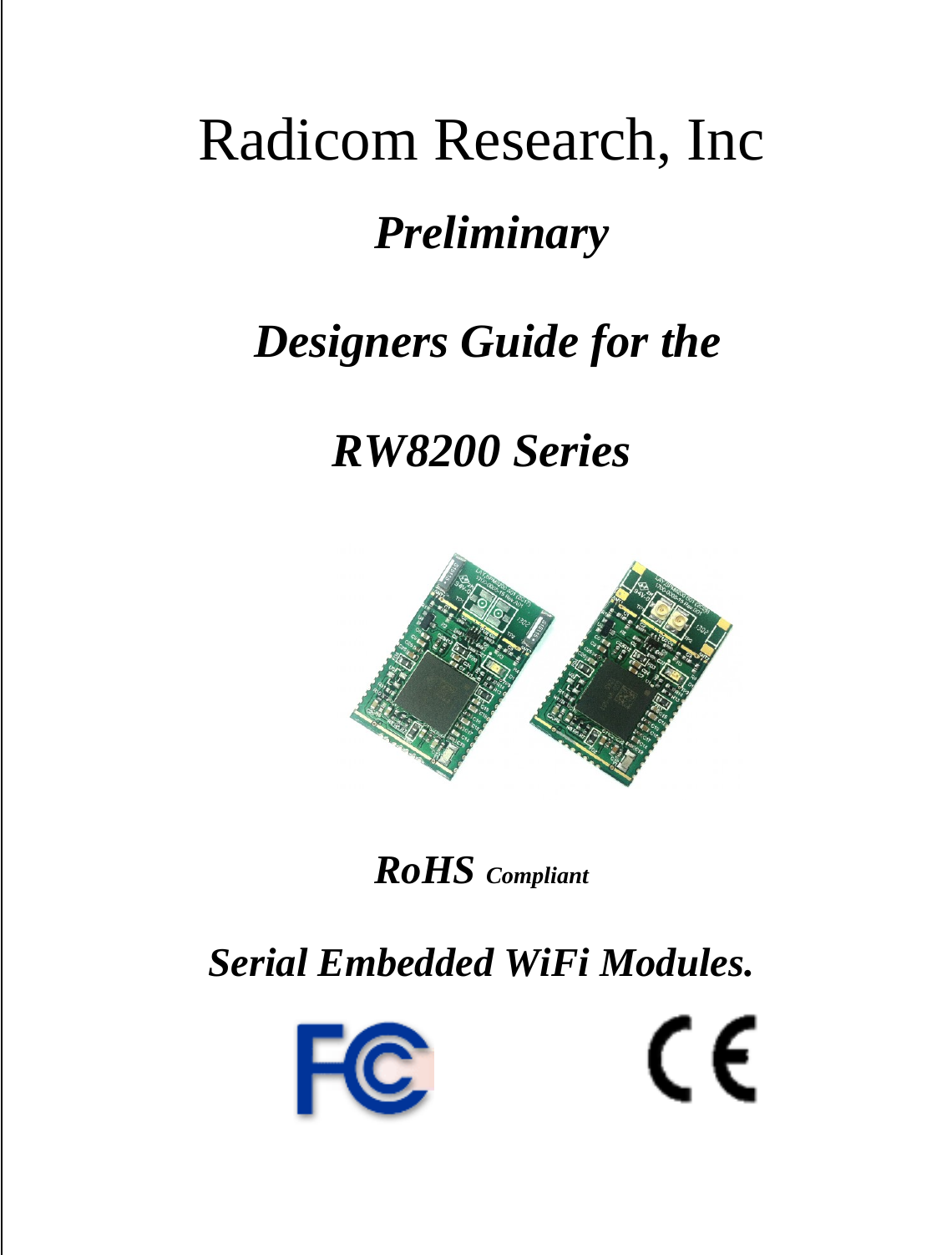

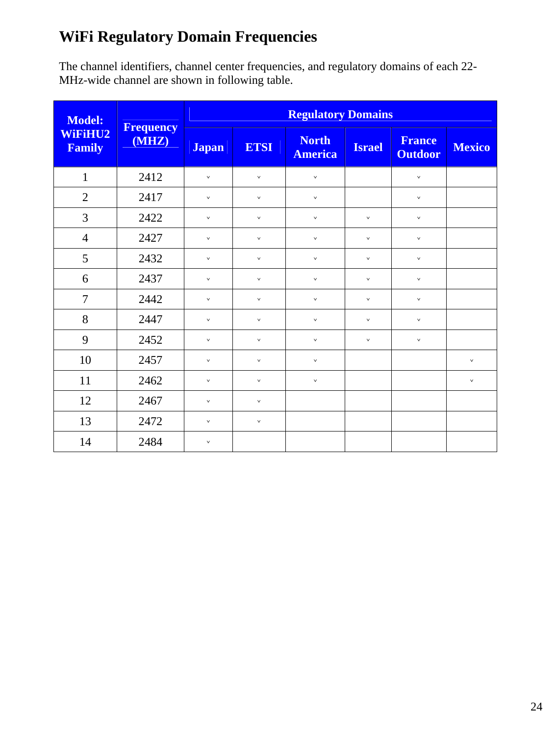
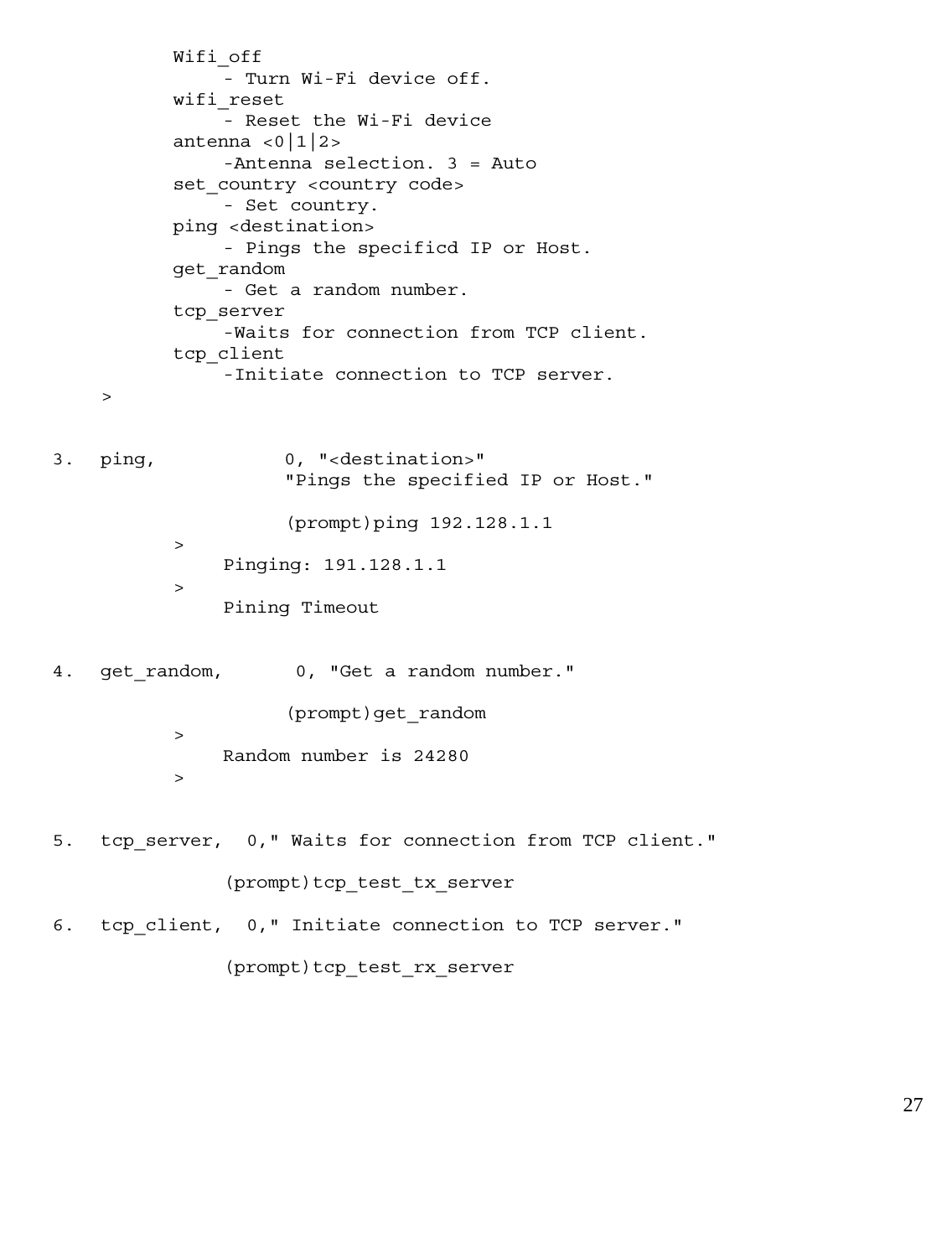
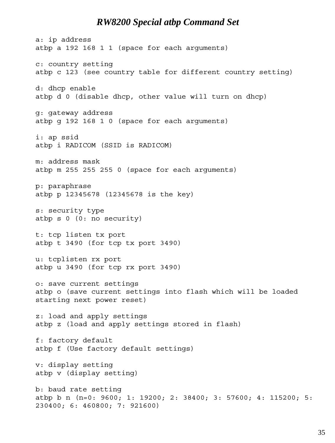
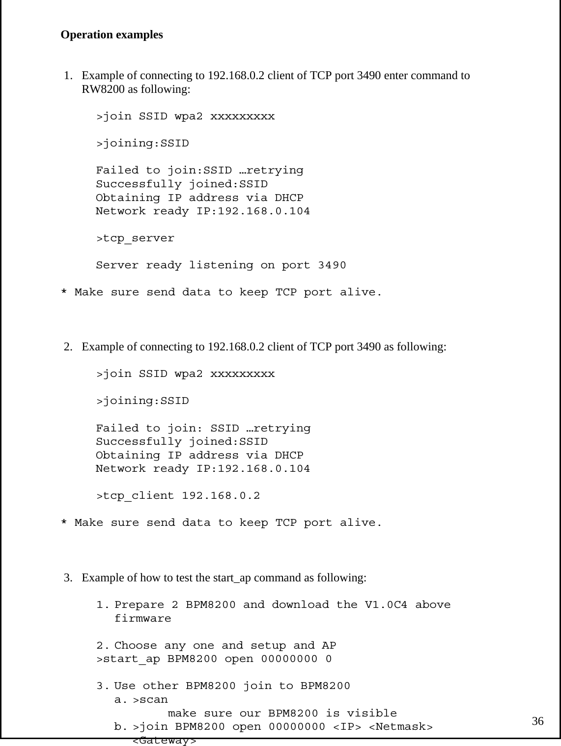
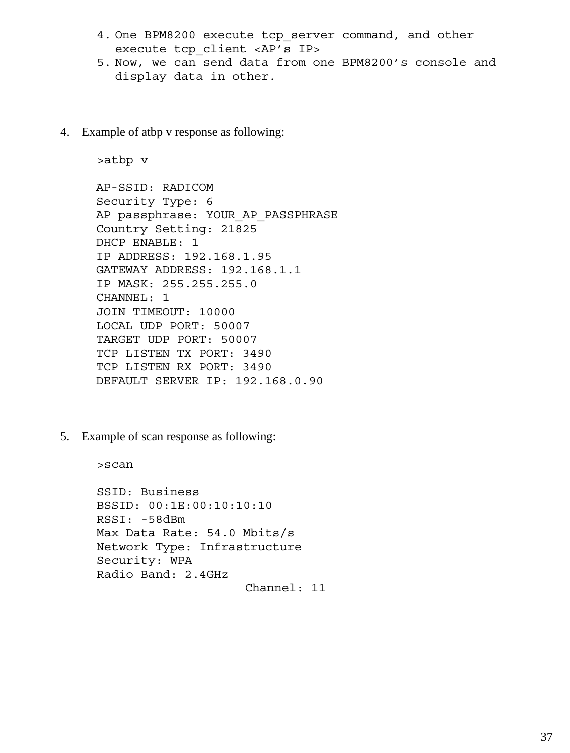
![Important features: 1. Antenna types The RW8200 can have either an ON Board Chip antennae or an U.FL connector for external antennae connections. 2. Serial Port The RW8200 supports serial port and can set baud rate from 1200 up to 921600 bps. The default speed is 115200bps with one start, 1stop and no parity bit. When power on, if pin 20 signal is pulled low, the default speed is 115200bps. 3. Command/data mode To exit from data mode, you can issue an Escape sequence (+++) or use pin 20 of RW8200 module and RW8200-HM. 4. Flow control No flow control is needed for Network protocol. The BPM8200 does not have flow control at all. RW8200 COMMAND SET Command ParameterDescriptions ? 0, “Help menu” help 0, “Help menu” ping, 0, “<destination>” “Pings the specified IP or Host.” get_random, 0, “Get a random number.” get_mac_addr, 0, “Get the device MAC address.” get_rssi, 0, “Get the received signal strength of the AP (client mode only).” tcp_server, 0, “Turn on TCP Server mode.” tcp_client, 1, “Turn on TCP Client mode.” join, 2, “<ssid><open|wpa|wpa2>[key][ip netmask gateway]” “Join an AP. DHCP assumed if no IP address provided” join, 4, “<ssid><open|wpa|wpa2><key>[ip netmask gateway]” “Join a specific AP. DHCP assumed if no IP address provided.” leave, 0, “Leave an AP.” powersave, 1, “Enable/disable power save mode.” scan, 0, “Scan all enabled channels and print a list of APs found.” set_ip, 3, “Set a static IP.” set_tx_power, 1, “Set the tx power in dBm.” get_tx_power, 0, “Gets the tx power in dBm.” status, 0, “Print status of the WiFi and network 25](https://usermanual.wiki/Radicom-Research/RW8200/User-Guide-2214076-Page-27.png)
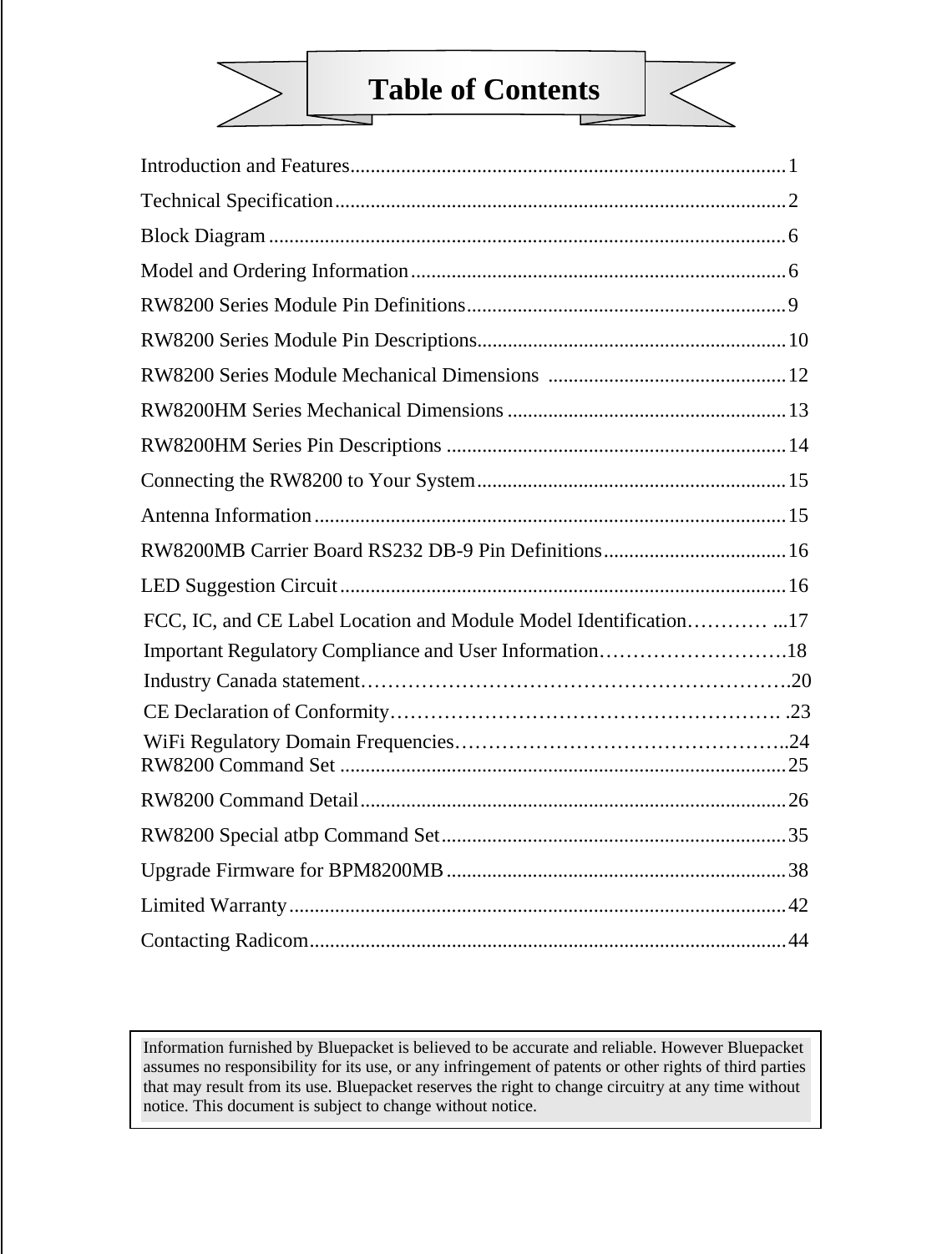
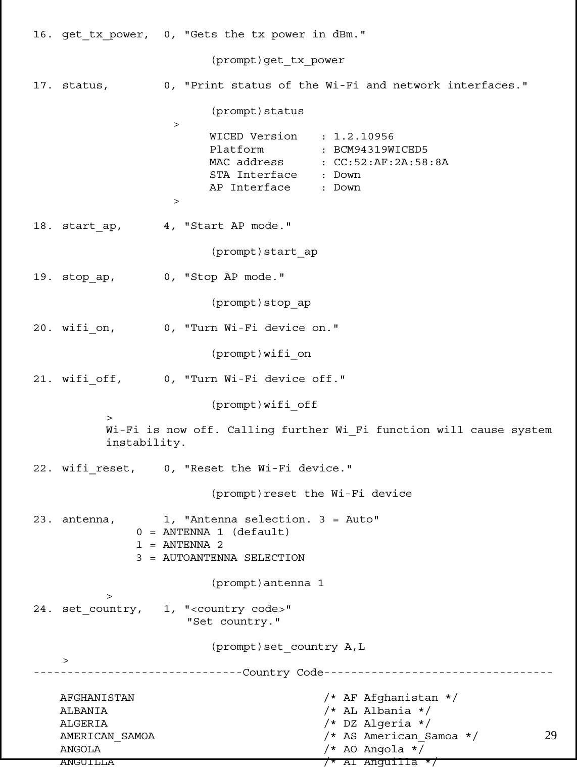
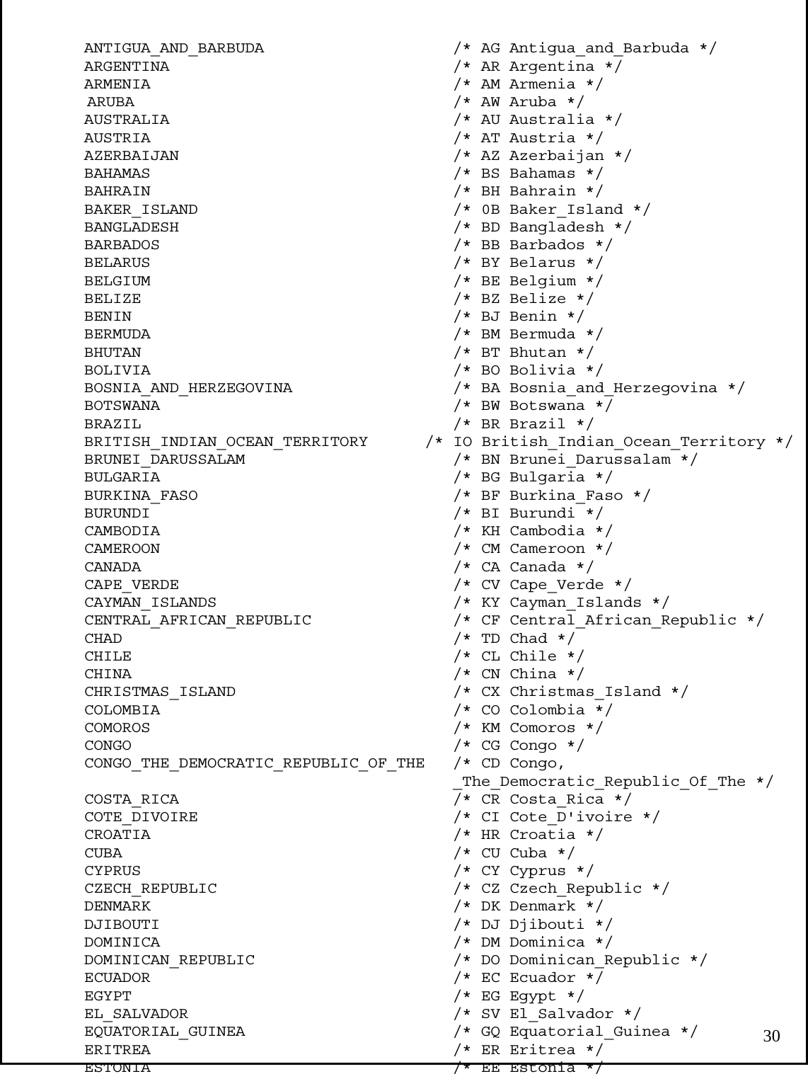
![interfaces.” start_ap, 4, “Start AP mode.” stop_ap, 0, “Stop AP mode.” wifi_on, 0, “Turn WiFi device on.” wifi_off, 0, “Turn WiFi device off.” wifi_reset, 0, “Reset the WiFi device.” antenna, 1, “Antenna selection. 3 = Auto” set_country, 1, “<country code>” “Set country.” RW8200 COMMAND Detail 1. ? 0, "Help menu" (prompt)? 2. help 0, "Help menu" (prompt)HELP > console Commands: help [<command> [<example_num>]] - Print help message or command example. dhcp - Perform DHCP as a client to obtain an IP address. get_mac_addr - Get the device MAC address get_rssi - Get the received signal strength of the AP (client mode only) join <ssid> <open|wpa|wpa2> [key] [ip netmask gateway] - Join an AP. DHCP assumed if no IP address provided join_specific <ssid> <bssid> <channel> <open|wpa|wpa2> <key> [ip netmask gateway] - Join a specific AP. DHCP assumed if no IP address provided leave - Leave an AP. Powersave <1|0> - Enable/Disable powersave mode. scan - Scan all enabled channels and print a list of APs found. set_ip <ip> <network> <gateway> -Set a static IP. set_tx_power <0-32> - Set the tx power in dBm. get_tx_power - Gets the rx power in dBm. status - Print status of the Wi-Fi and network interfaces. start_ap <ssid> <open|wpa|wpa2> <key> <channel> - Start AP mode stop_ap Stop AP mode wifi_on - Turn Wi-Fi device on. 26](https://usermanual.wiki/Radicom-Research/RW8200/User-Guide-2214076-Page-28.png)
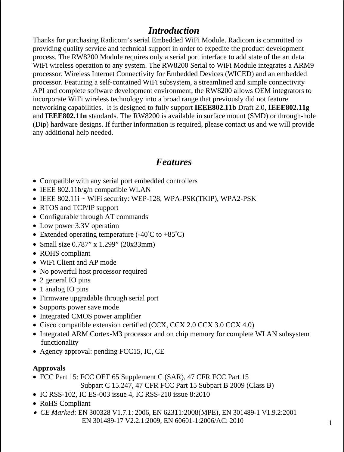
![7. get_mac_addr, 0, "Get the device MAC address." (prompt)get_mac_addr MAC address is : CC:52:AF:2A:58:8A 8. get_rssi, 0, "Get the received signal strength of the AP (client mode only)." (prompt)get_rssi RSSI is 0 9. join 2, "<ssid> <open|wpa|wpa2> [key] [ip netmask gateway]" "Join an AP. DHCP assumed if no IP address provided" (prompt)join 10. join_specific, 4, "<ssid> <bssid> <channel> <open|wpa|wpa2> <key> [ip netmask gateway]" "Join a specific AP. DHCP assumed if no IP address provided" (prompt)join_specific 11. leave, 0, "Leave an AP." (prompt)leave > 12. powersave, 1, "Enable/disable powersave mode." (prompt)powersave > 13. scan, 0, "Scan all enabled channels and print a list of APs found." (prompt)scan SSID : Business BSSID : 00:1E:00:10:10:10 RSSI : -58dBm Max Data Rate : 54.0 Mbits/s Network Type : Infrastructure Security : WPA Radio Band : 2.4GHz Channel : 11 14. set_ip, 3, "Set a static IP." (prompt)set_ip 15. set_tx_power, 1, "Set the tx power in dBm." (prompt)set_tx_power 28](https://usermanual.wiki/Radicom-Research/RW8200/User-Guide-2214076-Page-30.png)
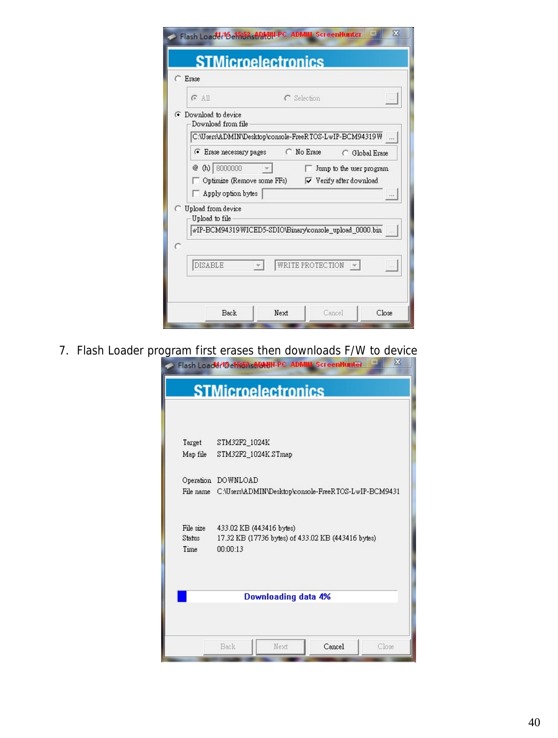
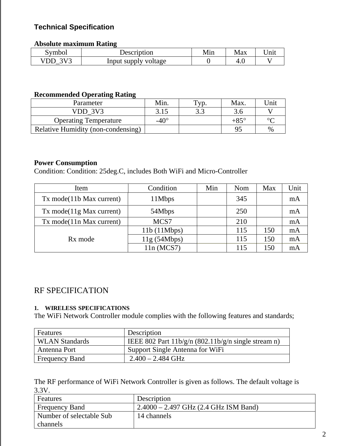
![Upgrade Firmware for RW8200-MB 1. Install STMicroelectronics “Flash Loader Demonstrator” program. 2. Enable RW8200-MB to be Uart D/L mode (ADC3 pulled high) 3. Reset RW8200-MB, execute “Flash Loader Demonstrator” w/ correct COM port selected, press [Next] 4. “Target available…” should be displayed (as below), press [Next]; if not, close the program and repeat step #3 38](https://usermanual.wiki/Radicom-Research/RW8200/User-Guide-2214076-Page-40.png)
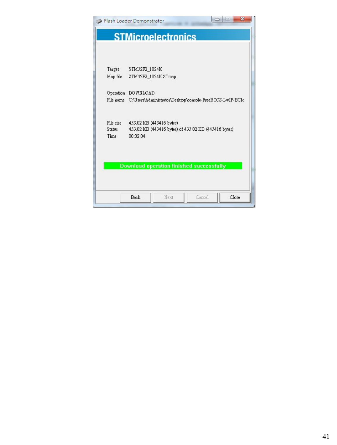
![5. From the “Target” pull-down menu, choose “STMF32F2_1024K”, press [Next] 6. Specify the to-be-upgraded F/W path (the example shows “console-FreeRTOS-LwIP-BCM94319WICED5-SDIO.hex”), press [Next] 39](https://usermanual.wiki/Radicom-Research/RW8200/User-Guide-2214076-Page-41.png)