Radicom Research WIFIHU-A USB WiFi Module User Manual Ethan Frome
Radicom Research Inc USB WiFi Module Ethan Frome
UserManual.wiki
>
Radicom Research
>
WIFIHU A User Manual
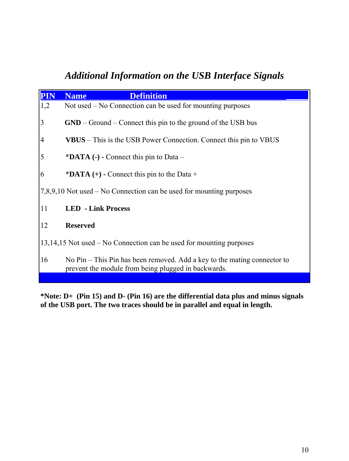
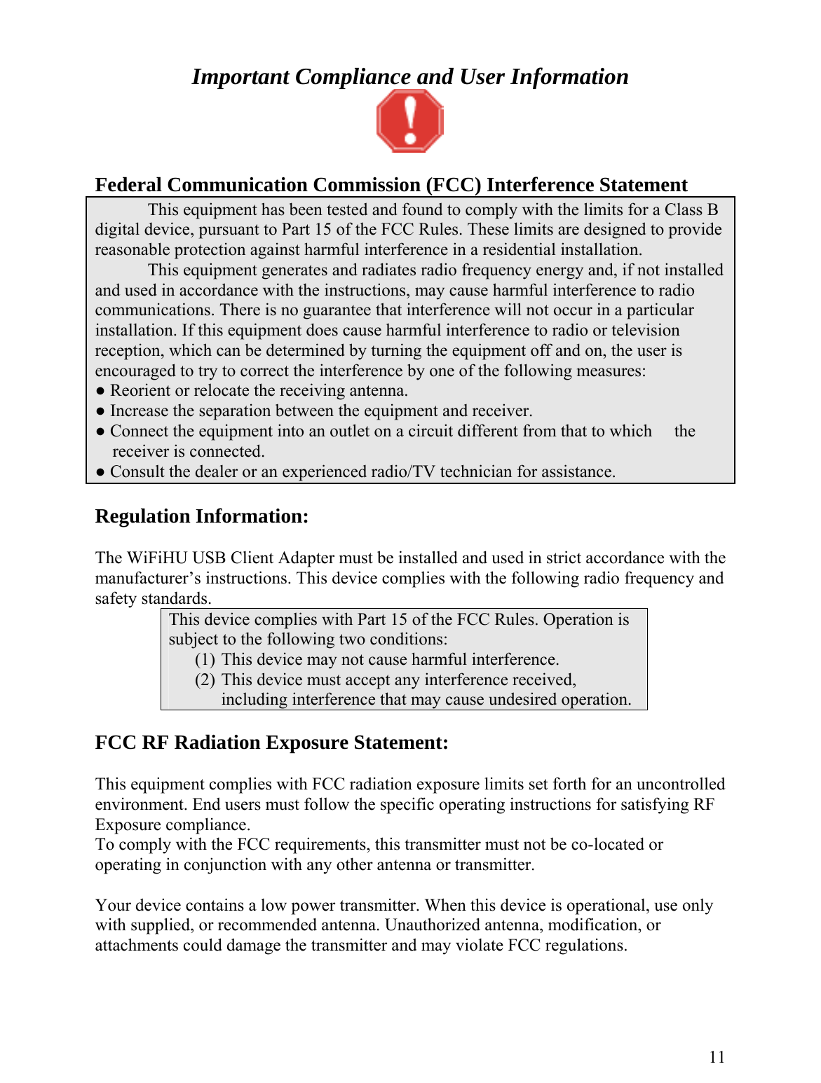
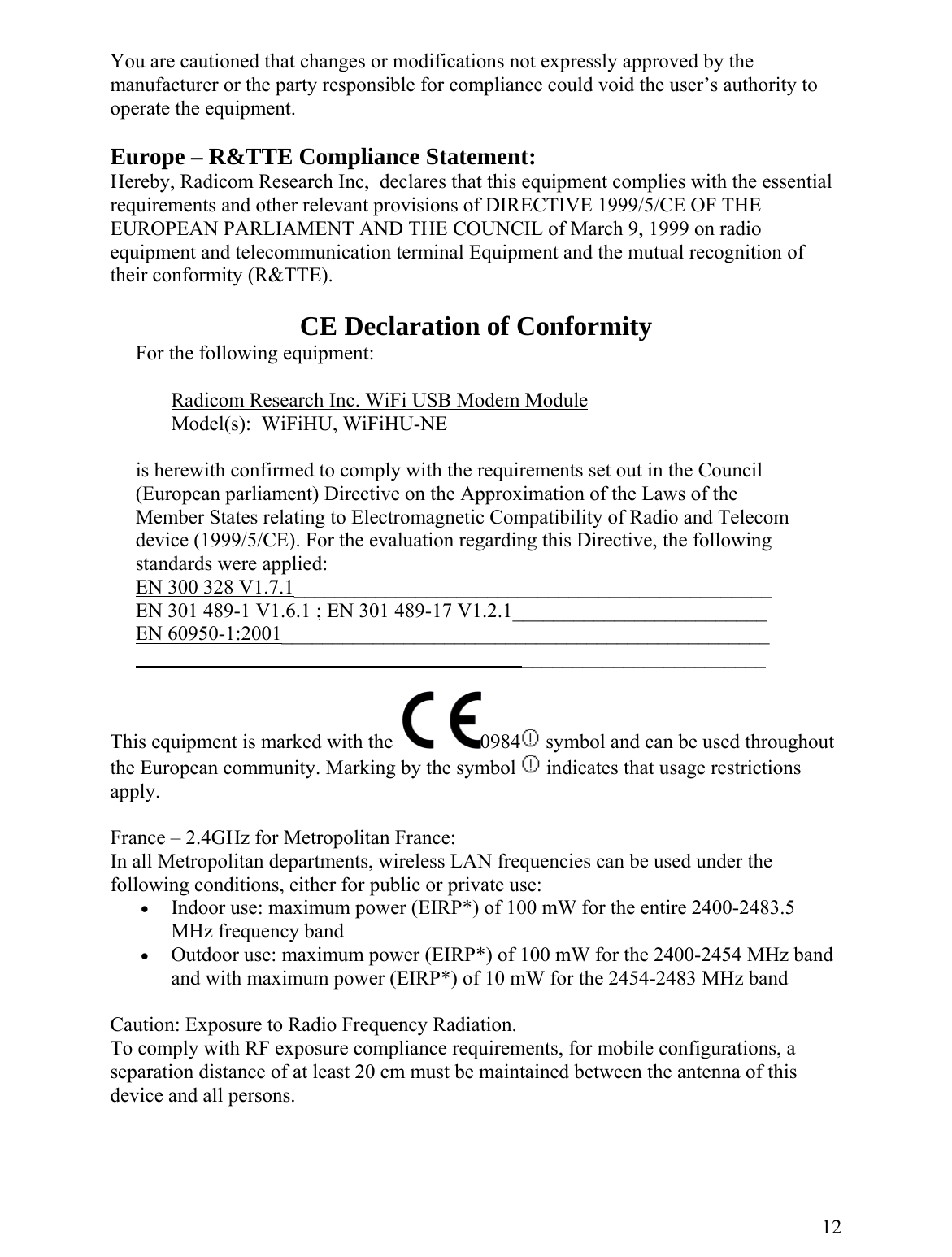
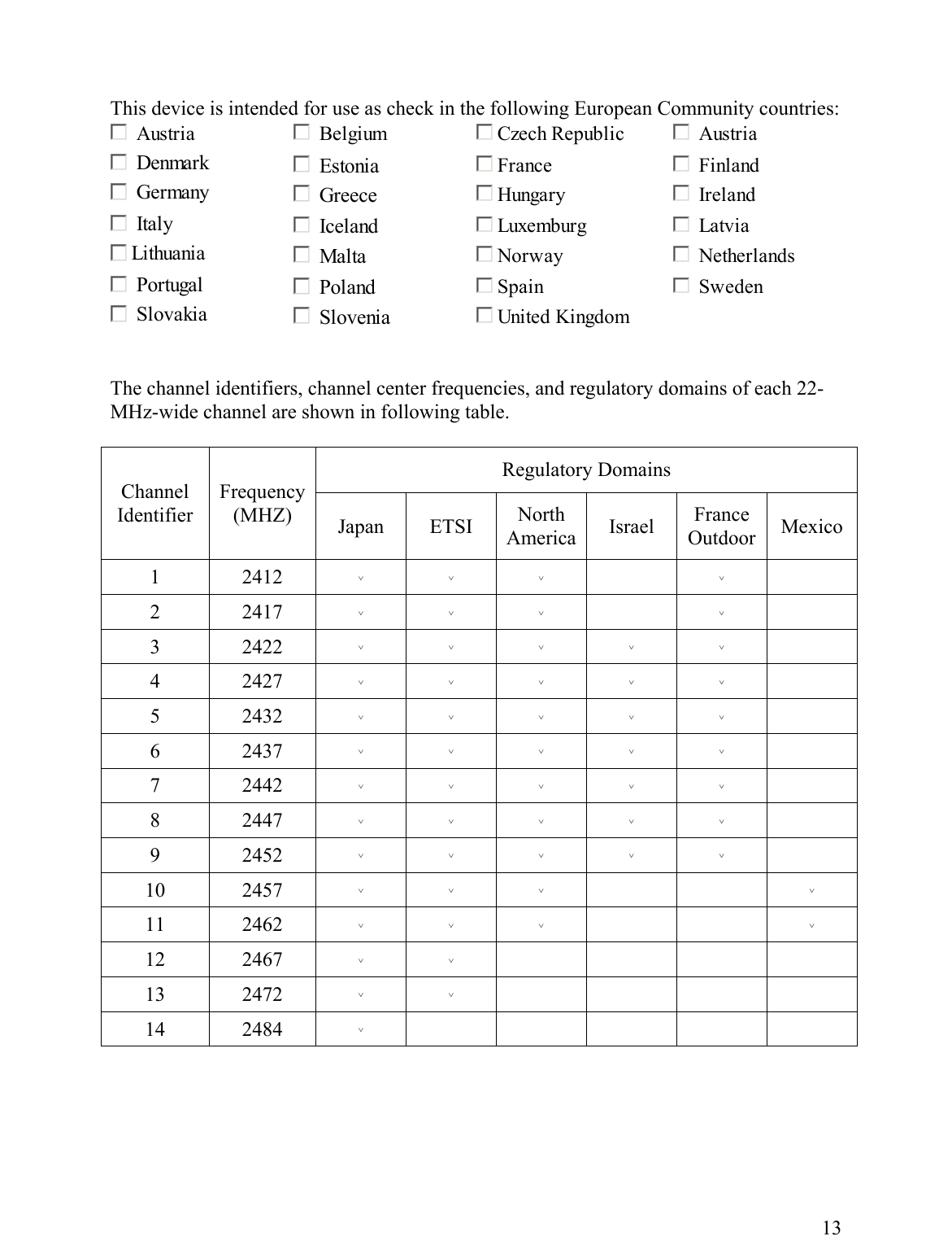
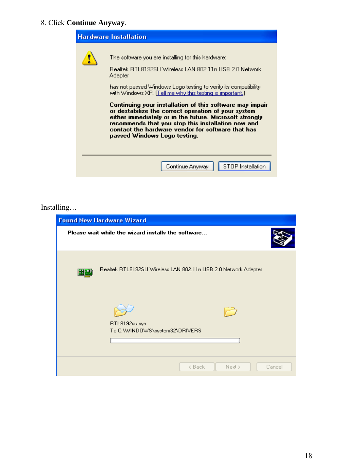
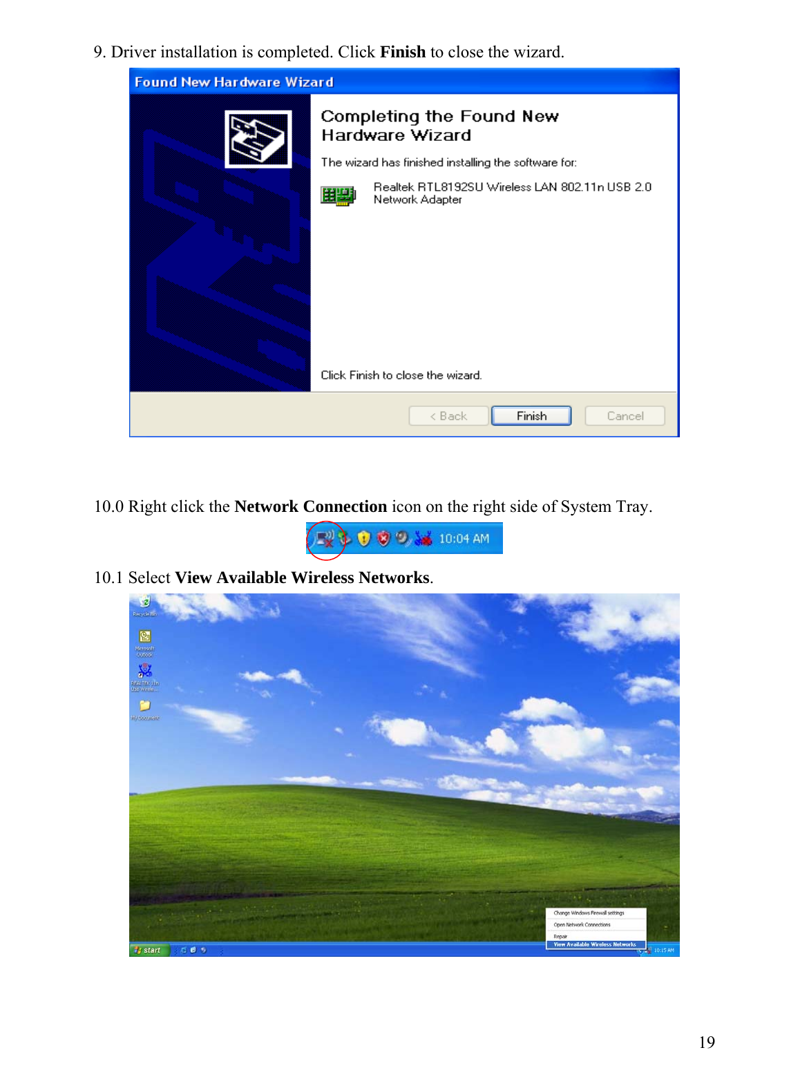
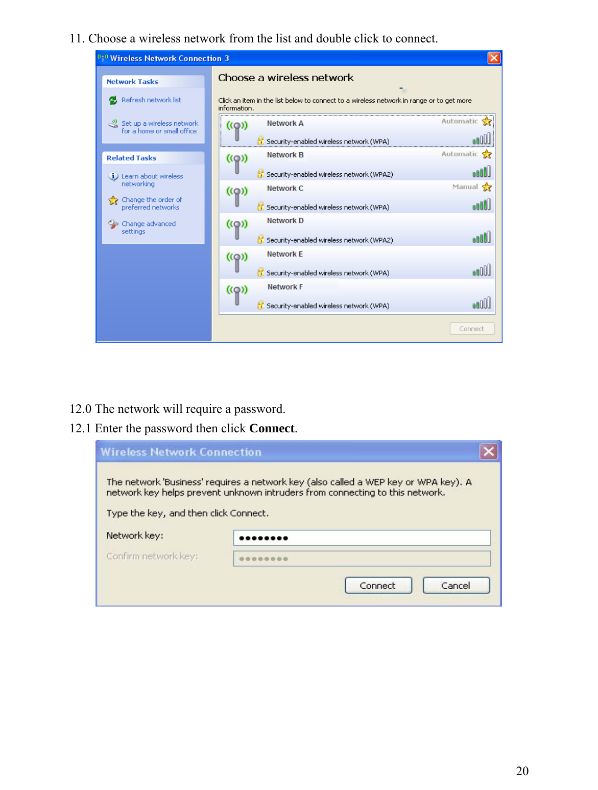
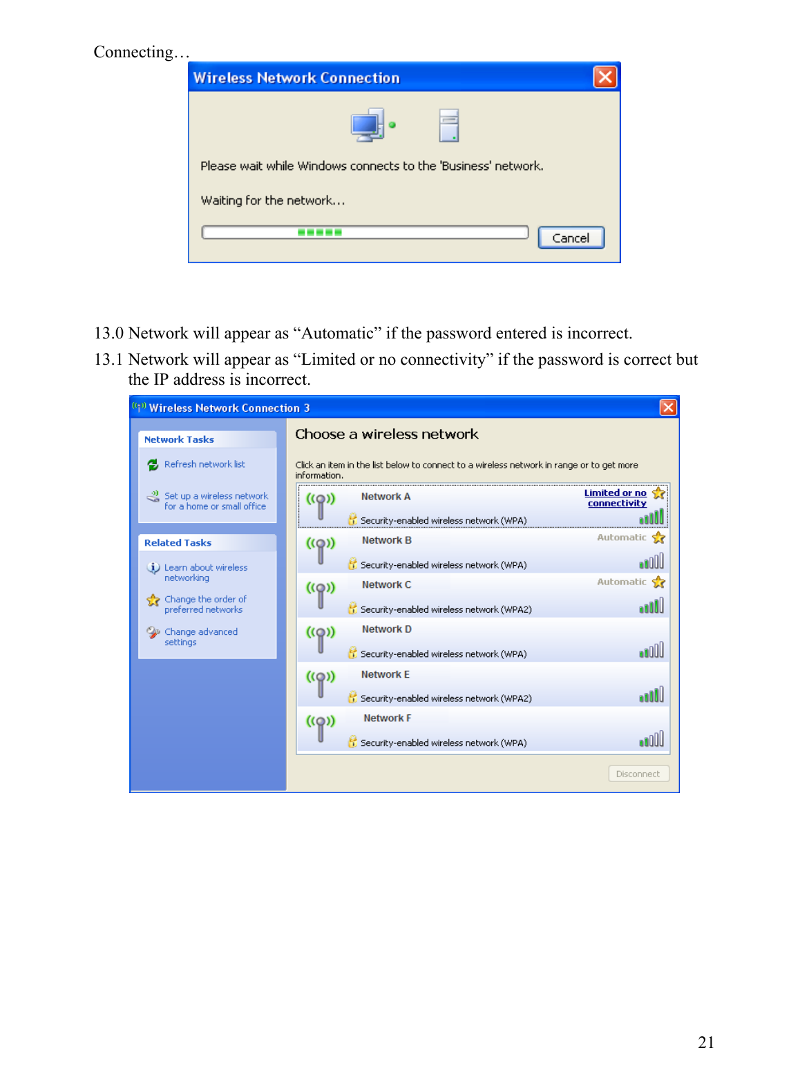
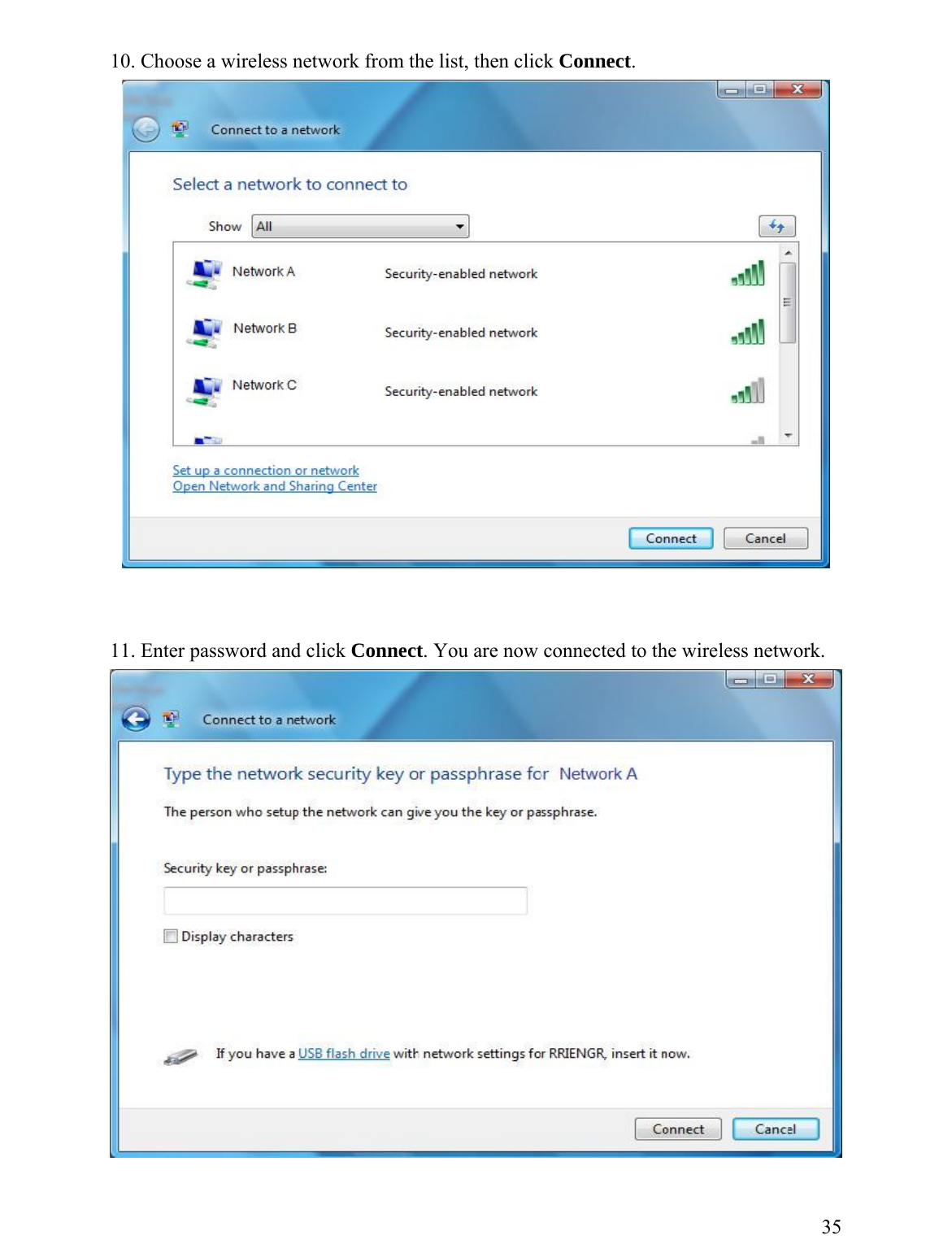
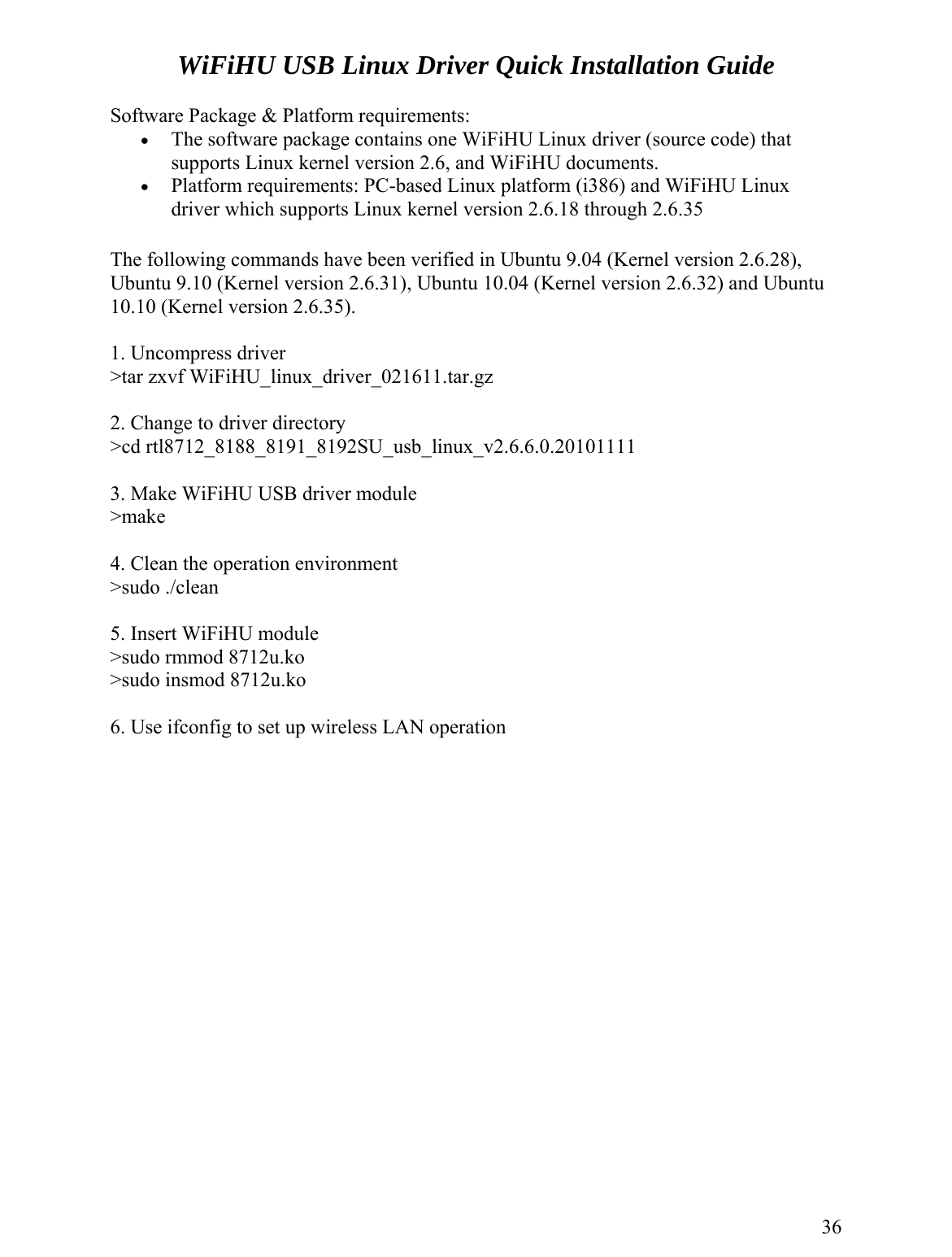
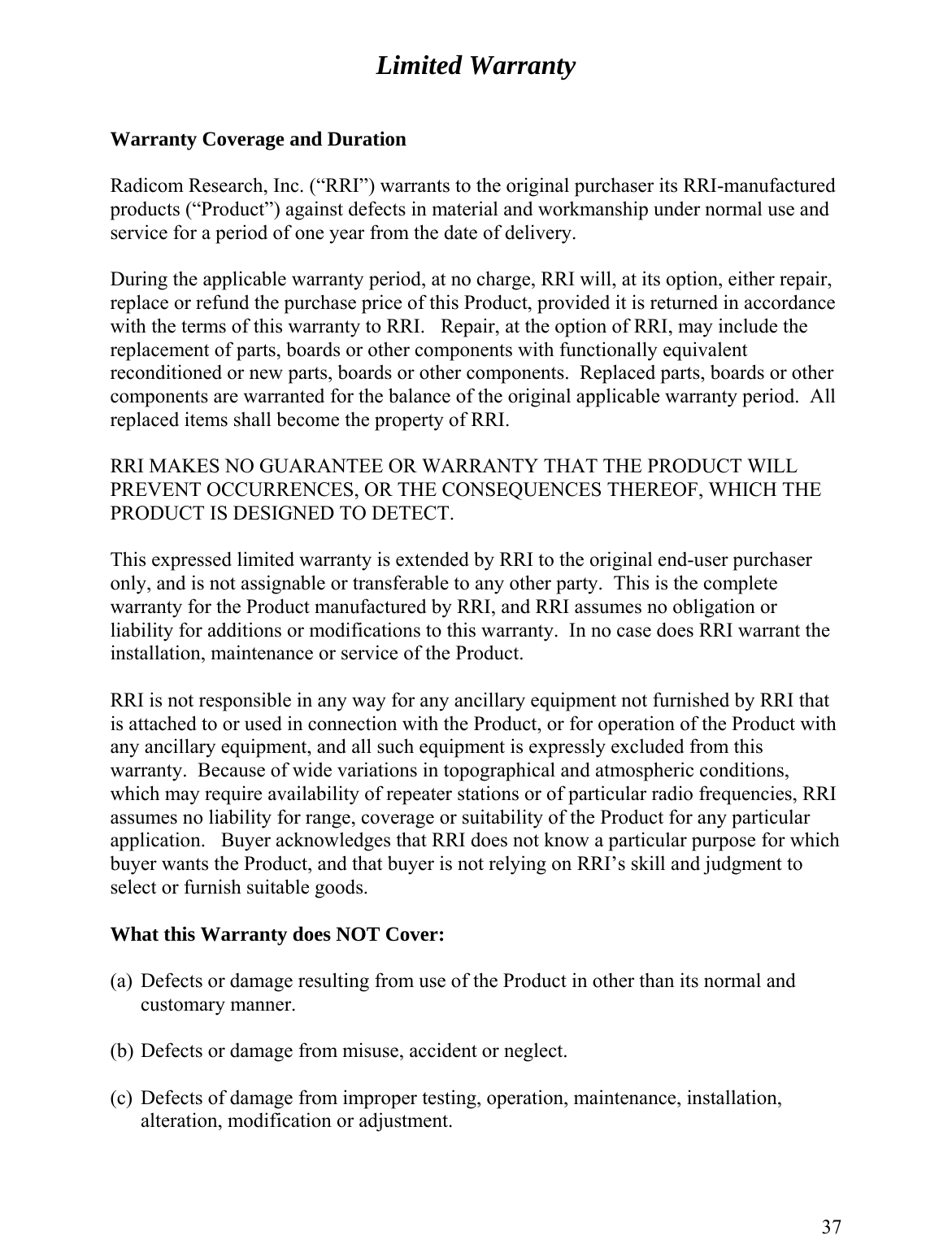
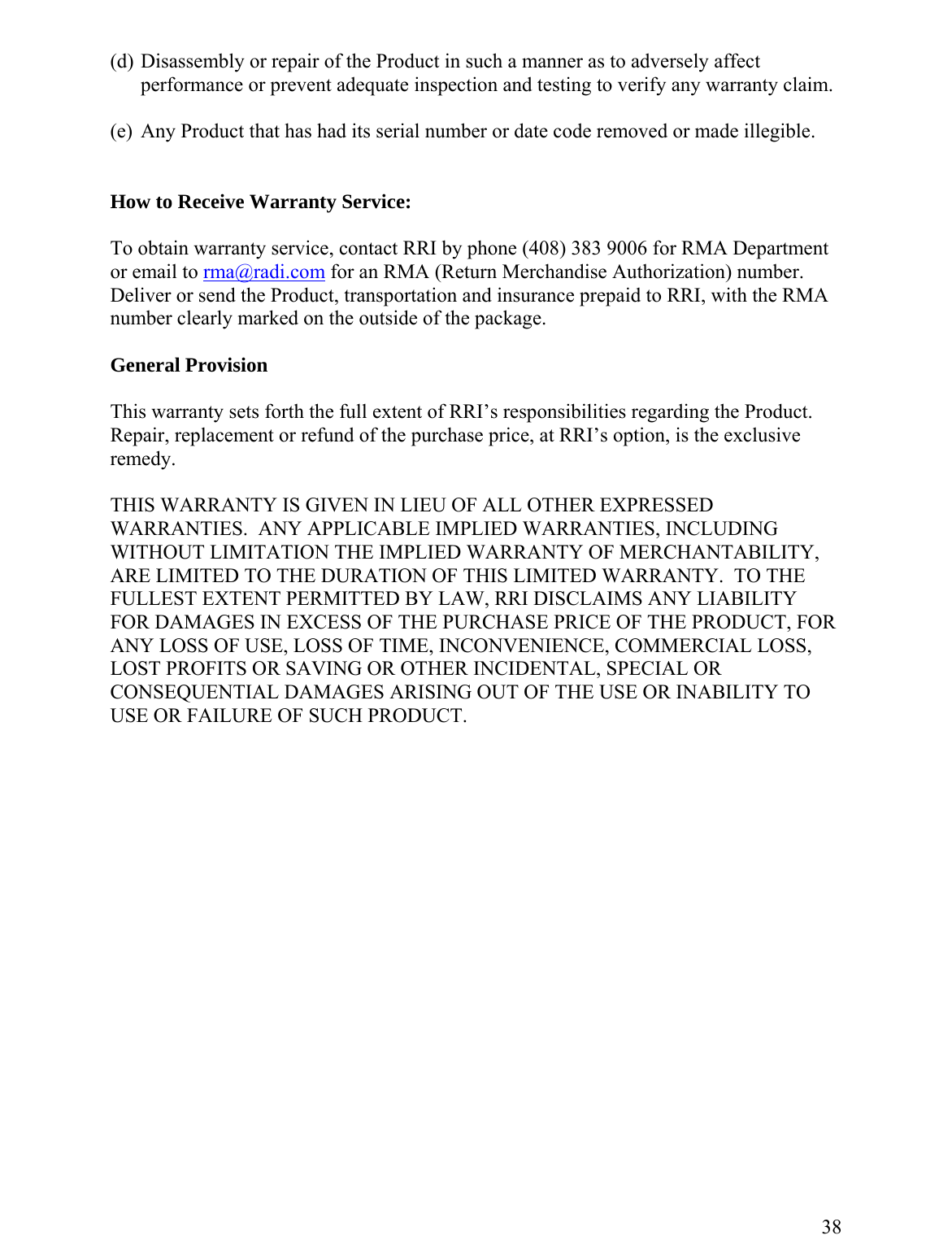
Users Manual
Navigation menu
Upload a User Manual
Namespaces
Wiki Guide
HTML
PDF
Info
Views
User Manual
Discussion / Help
Navigation