Radicom Research WIFIHU-A USB WiFi Module User Manual Ethan Frome
Radicom Research Inc USB WiFi Module Ethan Frome
Users Manual
Radicom Research, Inc.
Preliminary
Designers Guide for the
WiFiHU-NE and WiFiHU
USB WiFi Modules
RoHS Compliant
February 17, 2011

Table of Contents
Introduction and Features 3
Ratings and Block Diagram 4
Model and Ordering Information 5
Connecting the WiFiHU or WiFiHU-NE to Your System 6
Mechanical Specification and Pin Orientation for the WiFiHU 7
Mechanical Specification for the WiFiHU USB HUB 8
WiFiHU USB Interface Pins 9
Additional Information on the Interface Signals 10
Important Compliance and User Information 11
Driver Installation Guide For Windows XP/2K 14
Driver Installation Guide For Windows 7 25
Driver Installation Guide For Windows Vista 30
WiFiHU USB Linux Driver Quick Installation Guide 36
Limited Warranty 37
Contacting Radicom Research 39
Introduction
2
Information furnished by Radicom Research is believed to be accurate and reliable. However
Radicom Research assumes no responsibility for its use, or any infringement of patents or other
rights of third parties that may result from its use. Radicom Research reserves the right to change
circuitry at any time without notice. This document is subject to change without notice.

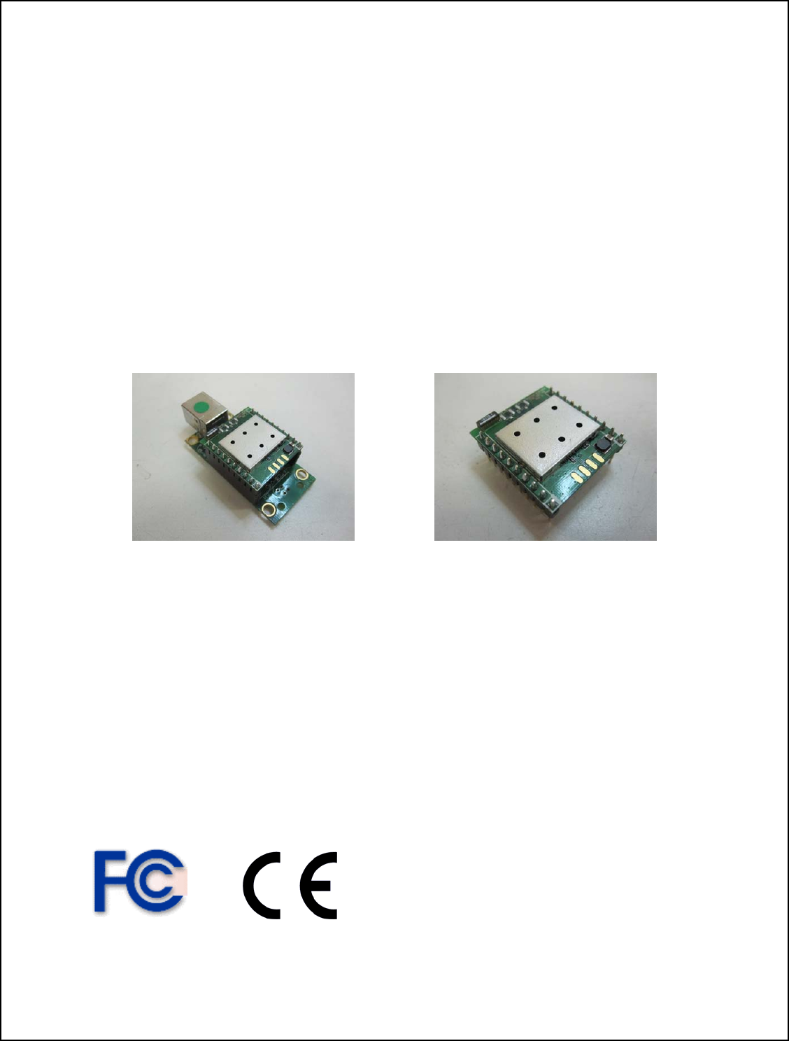
Thanks for purchasing Radicom Research’s USB WiFi Module. Radicom is committed to
providing quality service and technical support in order to expedite the product
development process. The WiFiHU Module requires only a USB (Universal Serial Bus)
interface to add state of the art data WiFi wireless operation to any system. It is designed
to fully support IEEE802.11n™ Draft 2.0, IEEE802.11e™ and IEEE802.11i™
standards. If further information is required, please contact us and we will provide any
additional help needed. Features
• Compatible with both USB 1.1 and USB 2.0 host controllers
• USB 2.0 Compatible Hot Swappable Interface
• IEEE 802.11b/g/n compatible WLAN
• 1x2 MIMO technology for extended reception robustness and exceptional throughput
• 150Mbps receive PHY rate and 75Mbps transmit PHY rate using 20MHz bandwidth
• 300Mbps receive PHY rate and 150Mbps transmit PHY rate using 40MHz bandwidth
• 20MHz and 40MHz bandwidth transmission
• Operates in 2.4GHz Frequency Range
• Compatible with 802.11n draft 2.0 specification
• Backward compatible with 802.11b/g devices while operating at 802.11n data rates
• Frame aggregation for increased MAC efficiency (A-MSDU, A-MPDU)
• Low latency immediate High-Throughput Block Acknowledgement (HT-BA)
• Long NAV for media reservation with CF-End for NAV release
• PHY-level spoofing to enhance legacy compatibility
• MIMO power saving mechanism
• Channel management and co-existence
• Multiple BSSID feature allows the RTL8191SU-GR to assume multiple MAC
identities when used as a wireless bridge
• Supports Wake-On-WLAN via Magic Packet and Wake-up frame
• Transmit Opportunity (TXOP) Short Inter-Frame Spaces (SIFS) bursting for higher
multimedia bandwidth
• One Transmit and Two Receive paths (1T2R)
• Short Guard Interval (400ns)
• DSSS with DBPSK and DQPSK, CCK modulation with long and short preamble
• OFDM with BPSK, QPSK, 16QAM, and 64QAM modulation
Convolutional Coding Rate: 1/2, 2/3, 3/4, and 5/6
• OFDM receive diversity with MRC using up to 2 receive paths. Switch diversity used
for DSSS/CCK
• Hardware antenna diversity
• Selectable digital transmit and receive FIR filters
• Programmable scaling in transmitter and receiver to trade quantization noise against
increased probability of clipping
• Fast receiver Automatic Gain Control (AGC)
• RoHS Compliant and CE Marked
3
Support
• IEEE 802.11b/g/n compatible WLAN
• IEEE 802.11e QoS Enhancement (WMM)
• IEEE 802.11h TPC, Spectrum Measurement
• IEEE 802.11i (WPA, WPA2). Open, shared key, and pair-wise key authentication
services
• Cisco Compatible Extensions (CCX4)
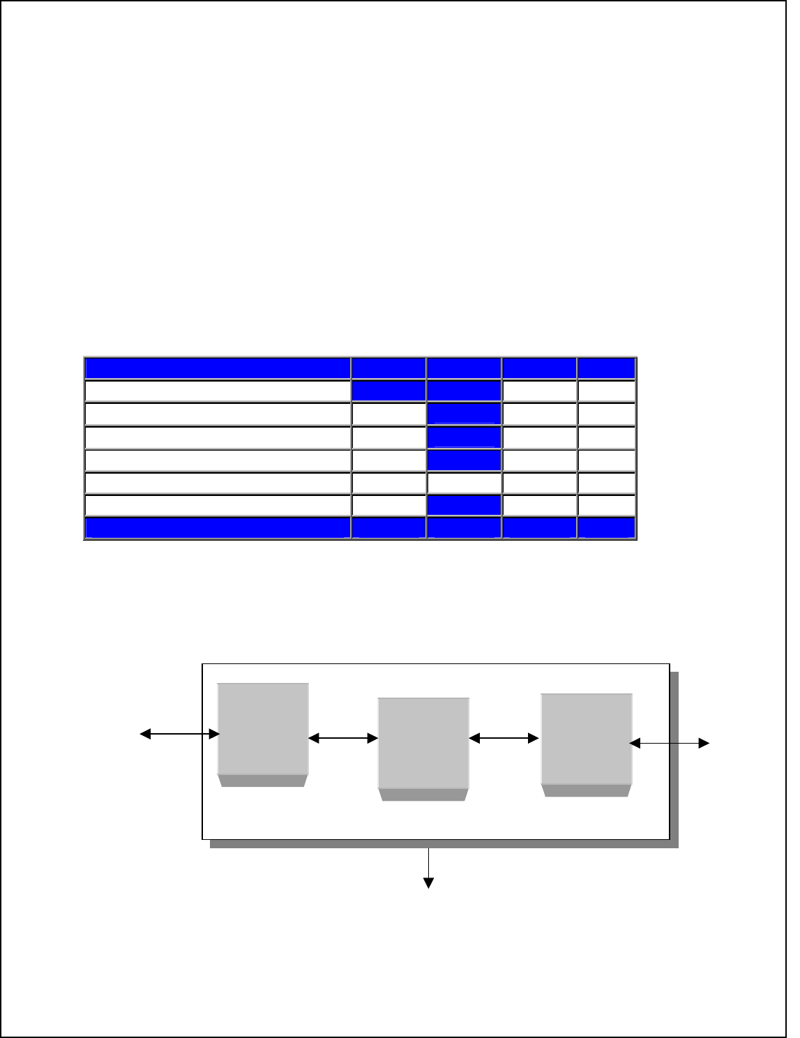
Ratings
Parameter Min Typical Max Units
Maximum Data Rate 300M bps
Operating Temperature HU 0° 70° °C
Storage Temperature 0° 125° °C
Relative Humidity (non-condensing) 5 % 95 %
Current Consumption 152 155 162 mA
Transmit & Receive Level -84(Rx) +17 (Tx) dBm
Block Diagram
4
USB
MAC
RF
USB
Port
USB MODULE
GND
Antenna

Model and Ordering Information
This versatile WiFiHU USB family of products offers various configuration options to
meet the specific system requirements a designer may need to add state of the art WiFi
USB operation. The WiFiHU is available as a module, a module with USB Jack and
antennae interface, or as a complete external device in an enclosure. The WiFiHU also
has three different antennae options.
Model Description Comments
WiFiHU-a WiFi USB Module with dual on
board chip antennae Uses onboard chip antennae. Not
for use with External Antenna.
Allows designer to determine
USB Jack placement.
WiFiHU-a-1-NE WiFiHU-a installed in a
WiFiHU-CB1 Carrier Board
with on board USB Jack.
Complete WiFi Module with
dual chip antennae with USB
Jack interface.
WiFiHU-a-1-UE WiFiHU-a and WiFiHU-CB1
installed in enclosure
Complete WiFi Standalone
model with on board dual chip
antenna and USB Jack mounted
in enclosure.
WiFiHU-c WiFi USB Module with two
SMD Connectors for attaching
antenna cable and 2.4GHz 2 dBi
Omni-directional antenna
Allows designer to determine
USB Jack and antenna
placement.
WiFiHU-c-1-NE WiFiHU-c installed in WiFiHU-
CB1 Carrier Board with on
board USB Jack.
Complete WiFi Module with
cable and antenna with USB
Jack interface.
WiFiHU-c-1-UE WiFiHU-c and WiFiHU-CB1
installed in enclosure Complete WiFi Standalone
model with cable, antenna and
USB Jack mounted in enclosure
WiFiHU-c-2-NE WiFiHU-c installed in WiFiHU-
CB2 Carrier Board with on
board RPSMA antenna Jack
and USB Jack
Complete WiFi Module with
Fixed location antenna and USB
Jack.
WiFiHU-c-2-UE Complete WiFi module with
antenna installed in a case. Complete WiFi USB Model with
antenna and USB Jack mounted
in enclosure.
5

Connecting the WiFiHU or WiFiHU-NE to Your System
The WiFiHU Modules are designed for easy connection to any standard USB Port and
wireless network. Connect one end of the USB cable into the USB connector on the
WiFiHU-NE and the other into any available USB receptacle on your computer. The
WiFiHU-NE’s “Hot Swap-able” interface allows you to plug or unplug the module even
when the computer is on. If using Windows, load the provided drivers. The WiFiHU-NE
is now ready for use.
If you plan to embed the WiFiHU into your system, the initial evaluation consists of the
WiFiHU USB Module mounted onto a USB hub PCB (WiFiHU-NE). To remove the
WiFiHU carefully remove it from the two 8 pin headers on the WiFiHU-NE USB
interface board. Save this interface board. The WiFiHU can always be reinstalled into the
WiFiHU-NE USB interface board and connected to any standard USB port to verify or
test the module functions. If you use external antenna, connect one end of Radicom
approved antenna to the on board socket.
6
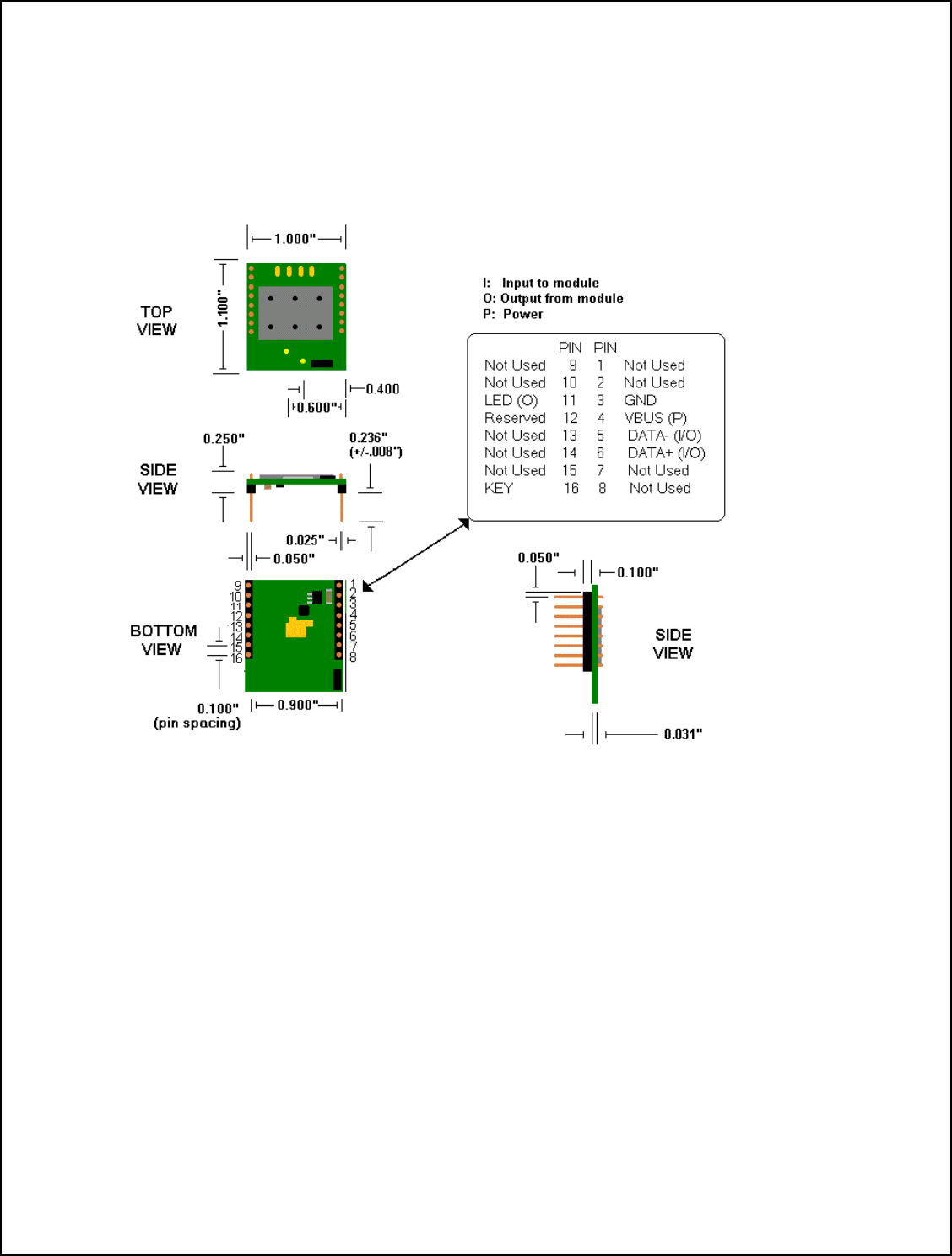
Mechanical Specification and Pin Orientation for the WiFiHU
The WiFiHU USB Half Inch Modules are designed for easy connection to any standard
USB interface and wireless network. The connection is made through two 8-pin headers,
which may be attached to your device via a socket or by individually hardwiring each
pin.
Notes:
1. Pin Spacing is 0.100 inch from center to center
2. Dimension of the WiFiHU module – 1.10 x 1.00 x 0.25 inch
3. Suggested mating female connector:
Samtec P/N. #SSW-110-21-G-S (RoHS Thru-Hole)
Samtec P/N. #SSW-110-22-G-S-VS (RoHS SMT)
4. Square pins – 0.025 x 0.025 inch
7
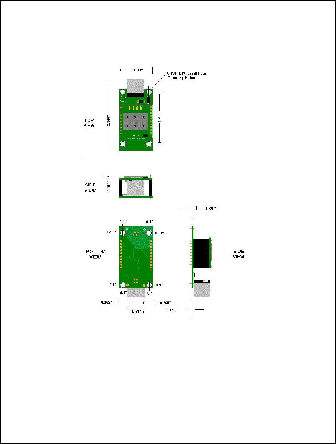
Mechanical Specification for the WiFiHU USB HUB
8

WiFiHU USB Interface Pins
The following shows the I/O Pins required for adding the WiFiHU USB Module to your
embedded system.
PIN Number Name Type
1 Not Used
2 Not Used
3 GND Ground
4 VBUS USB Power
5 DATA- Input / Output
6 DATA+ Input / Output
7 Not Used
8 Not Used
9 Not Used
10 Not Used
11 LED (O) Output
12 Reserved
13 Not Used
14 Not Used
15 Not Used
16 Key No Pin
9

Additional Information on the USB Interface Signals
PIN Name Definition _____
1,2 Not used – No Connection can be used for mounting purposes
3 GND – Ground – Connect this pin to the ground of the USB bus
4 VBUS – This is the USB Power Connection. Connect this pin to VBUS
5 *DATA (-) - Connect this pin to Data –
6 *DATA (+) - Connect this pin to the Data +
7,8,9,10 Not used – No Connection can be used for mounting purposes
11 LED - Link Process
12 Reserved
13,14,15 Not used – No Connection can be used for mounting purposes
16 No Pin – This Pin has been removed. Add a key to the mating connector to
prevent the module from being plugged in backwards.
*Note: D+ (Pin 15) and D- (Pin 16) are the differential data plus and minus signals
of the USB port. The two traces should be in parallel and equal in length.
10

Important Compliance and User Information
Federal Communication Commission (FCC) Interference Statement
This equipment has been tested and found to comply with the limits for a Class B
digital device, pursuant to Part 15 of the FCC Rules. These limits are designed to provide
reasonable protection against harmful interference in a residential installation.
This equipment generates and radiates radio frequency energy and, if not installed
and used in accordance with the instructions, may cause harmful interference to radio
communications. There is no guarantee that interference will not occur in a particular
installation. If this equipment does cause harmful interference to radio or television
reception, which can be determined by turning the equipment off and on, the user is
encouraged to try to correct the interference by one of the following measures:
● Reorient or relocate the receiving antenna.
● Increase the separation between the equipment and receiver.
● Connect the equipment into an outlet on a circuit different from that to which the
receiver is connected.
● Consult the dealer or an experienced radio/TV technician for assistance.
Regulation Information:
The WiFiHU USB Client Adapter must be installed and used in strict accordance with the
manufacturer’s instructions. This device complies with the following radio frequency and
safety standards.
This device complies with Part 15 of the FCC Rules. Operation is
subject to the following two conditions:
(1) This device may not cause harmful interference.
(2) This device must accept any interference received,
including interference that may cause undesired operation.
FCC RF Radiation Exposure Statement:
This equipment complies with FCC radiation exposure limits set forth for an uncontrolled
environment. End users must follow the specific operating instructions for satisfying RF
Exposure compliance.
To comply with the FCC requirements, this transmitter must not be co-located or
operating in conjunction with any other antenna or transmitter.
Your device contains a low power transmitter. When this device is operational, use only
with supplied, or recommended antenna. Unauthorized antenna, modification, or
attachments could damage the transmitter and may violate FCC regulations.
11
You are cautioned that changes or modifications not expressly approved by the
manufacturer or the party responsible for compliance could void the user’s authority to
operate the equipment.
Europe – R&TTE Compliance Statement:
Hereby, Radicom Research Inc, declares that this equipment complies with the essential
requirements and other relevant provisions of DIRECTIVE 1999/5/CE OF THE
EUROPEAN PARLIAMENT AND THE COUNCIL of March 9, 1999 on radio
equipment and telecommunication terminal Equipment and the mutual recognition of
their conformity (R&TTE).
CE Declaration of Conformity
For the following equipment:
Radicom Research Inc. WiFi USB Modem Module
Model(s): WiFiHU, WiFiHU-NE
is herewith confirmed to comply with the requirements set out in the Council
(European parliament) Directive on the Approximation of the Laws of the
Member States relating to Electromagnetic Compatibility of Radio and Telecom
device (1999/5/CE). For the evaluation regarding this Directive, the following
standards were applied:
EN 300 328 V1.7.1_______________________________________________
EN 301 489-1 V1.6.1 ; EN 301 489-17 V1.2.1_________________________
EN 60950-1:2001________________________________________________
________________________
This equipment is marked with the 0984 symbol and can be used throughout
the European community. Marking by the symbol indicates that usage restrictions
apply.
France – 2.4GHz for Metropolitan France:
In all Metropolitan departments, wireless LAN frequencies can be used under the
following conditions, either for public or private use:
• Indoor use: maximum power (EIRP*) of 100 mW for the entire 2400-2483.5
MHz frequency band
• Outdoor use: maximum power (EIRP*) of 100 mW for the 2400-2454 MHz band
and with maximum power (EIRP*) of 10 mW for the 2454-2483 MHz band
Caution: Exposure to Radio Frequency Radiation.
To comply with RF exposure compliance requirements, for mobile configurations, a
separation distance of at least 20 cm must be maintained between the antenna of this
device and all persons.
12

This device is intended for use as check in the following European Community countries:
Austria Belgium Czech Republic Austria
Denmark Estonia France Finland
Germany Greece Hungary Ireland
Italy Iceland Luxemburg Latvia
Lithuania Malta Norway Netherlands
Portugal Poland Spain Sweden
Slovakia Slovenia United Kingdom
The channel identifiers, channel center frequencies, and regulatory domains of each 22-
MHz-wide channel are shown in following table.
Regulatory Domains
Channel
Identifier
Frequency
(MHZ) Japan ETSI North
America Israel France
Outdoor Mexico
1 2412
∨ ∨ ∨ ∨
2 2417
∨ ∨ ∨ ∨
3 2422
∨ ∨ ∨ ∨ ∨
4 2427
∨ ∨ ∨ ∨ ∨
5 2432
∨ ∨ ∨ ∨ ∨
6 2437
∨ ∨ ∨ ∨ ∨
7 2442
∨ ∨ ∨ ∨ ∨
8 2447
∨ ∨ ∨ ∨ ∨
9 2452
∨ ∨ ∨ ∨ ∨
10 2457 ∨ ∨ ∨
∨
11 2462 ∨ ∨ ∨
∨
12 2467 ∨ ∨
13 2472 ∨ ∨
14 2484 ∨
13
Driver Installation Guide For Windows XP/2K
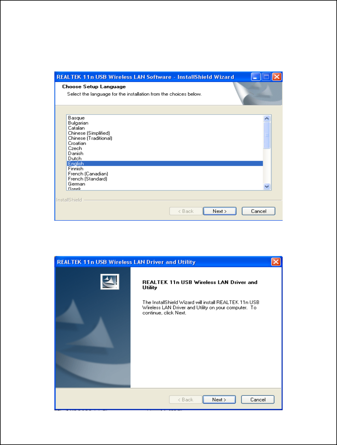
1.0 Insert the installation disc into CD-ROM.
1.1 Select your language from the Choose Setup Language drop-down list.
1.2 Click NEXT.
2. Click NEXT to continue.
14
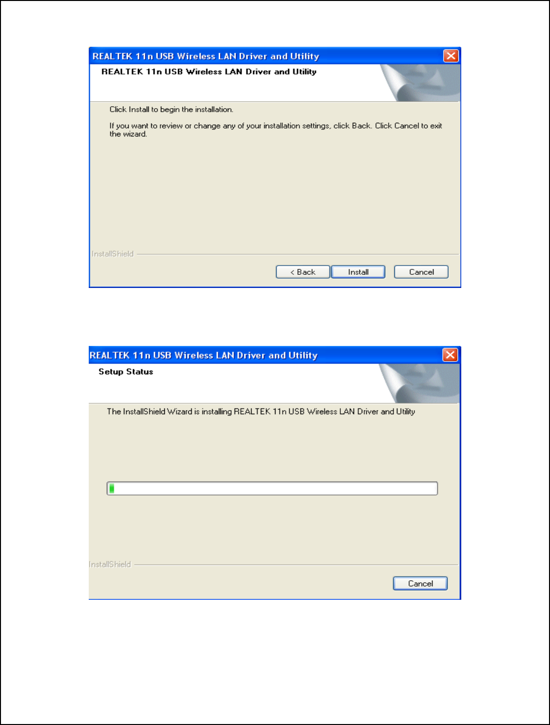
3. Click Install to begin the installation.
Installing…
15
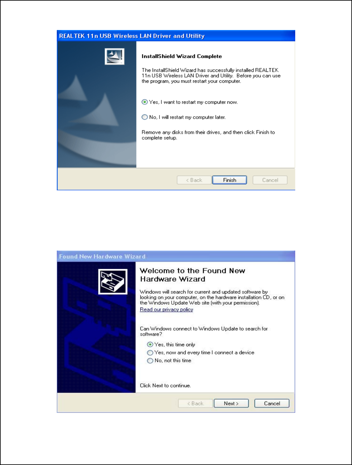
4. Click Finish to complete the installation.
5.0 Plug the device into the USB port.
5.1 Windows will automatically begin the installation for the device.
5.2 Click NEXT.
16
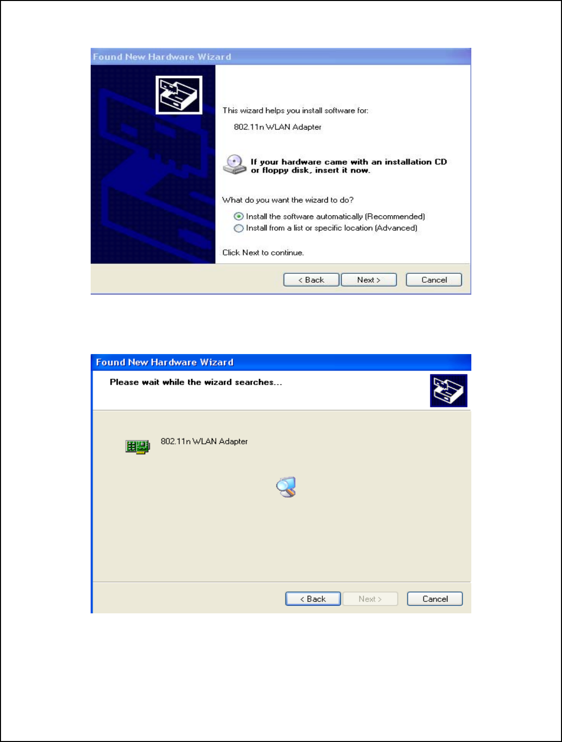
6. Click NEXT to begin the installation.
7. Windows will search for the software for the device.
17
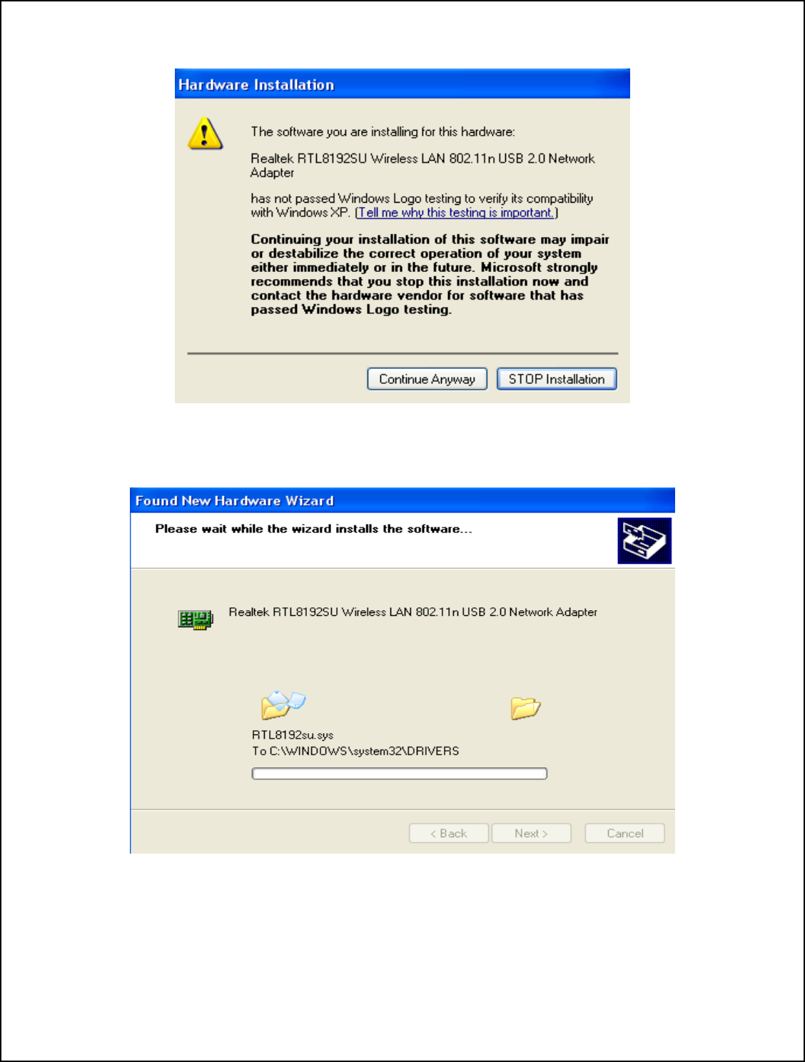
8. Click Continue Anyway.
Installing…
18
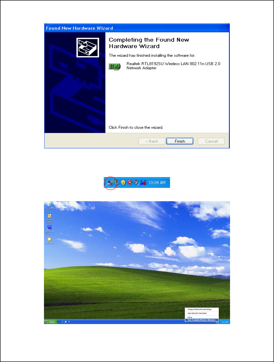
9. Driver installation is completed. Click Finish to close the wizard.
10.0 Right click the Network Connection icon on the right side of System Tray.
10.1 Select View Available Wireless Networks.
19
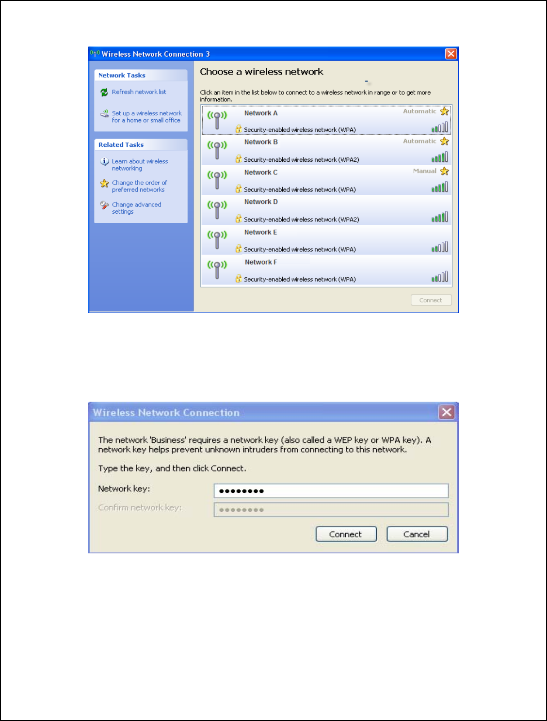
11. Choose a wireless network from the list and double click to connect.
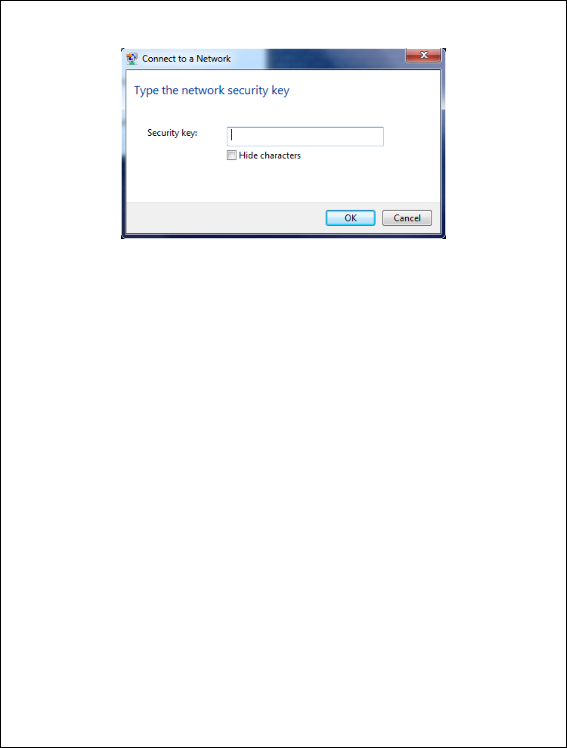
12.0 The network will require a password.
12.1 Enter the password then click Connect.
20
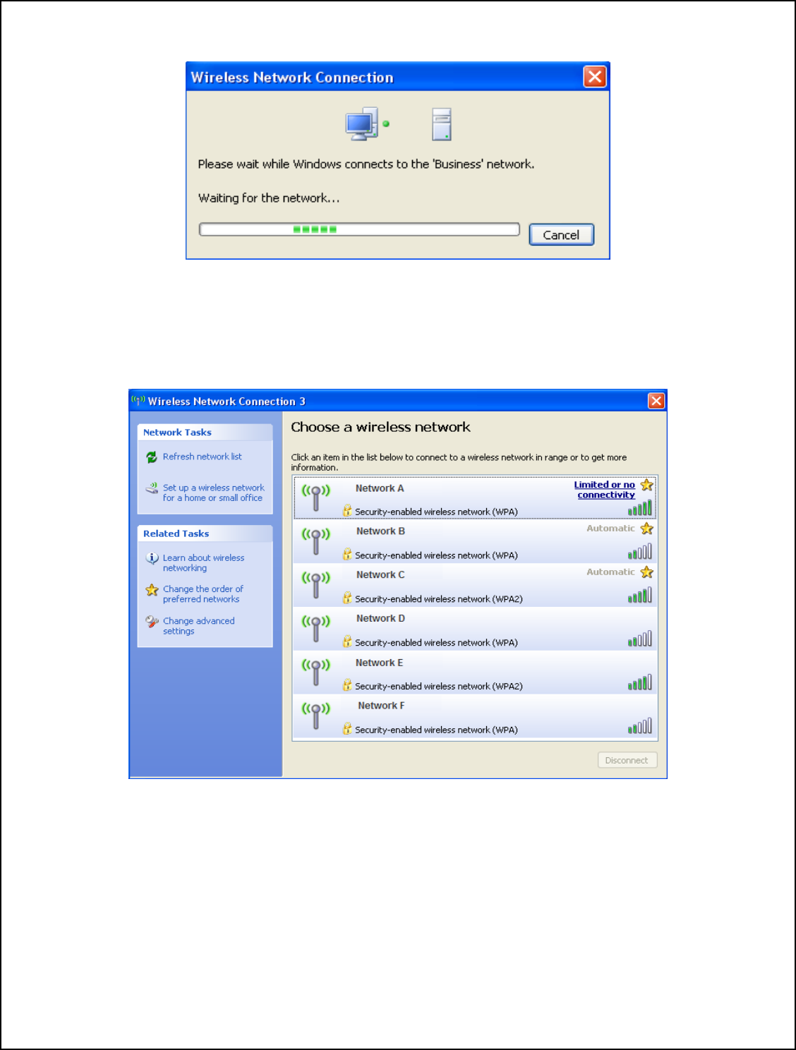
Connecting…
1
3.0 Network will appear as “Automatic” if the password entered is incorrect.
13.1 Network will appear as “Limited or no connectivity” if the password is correct but
the IP address is incorrect.
21
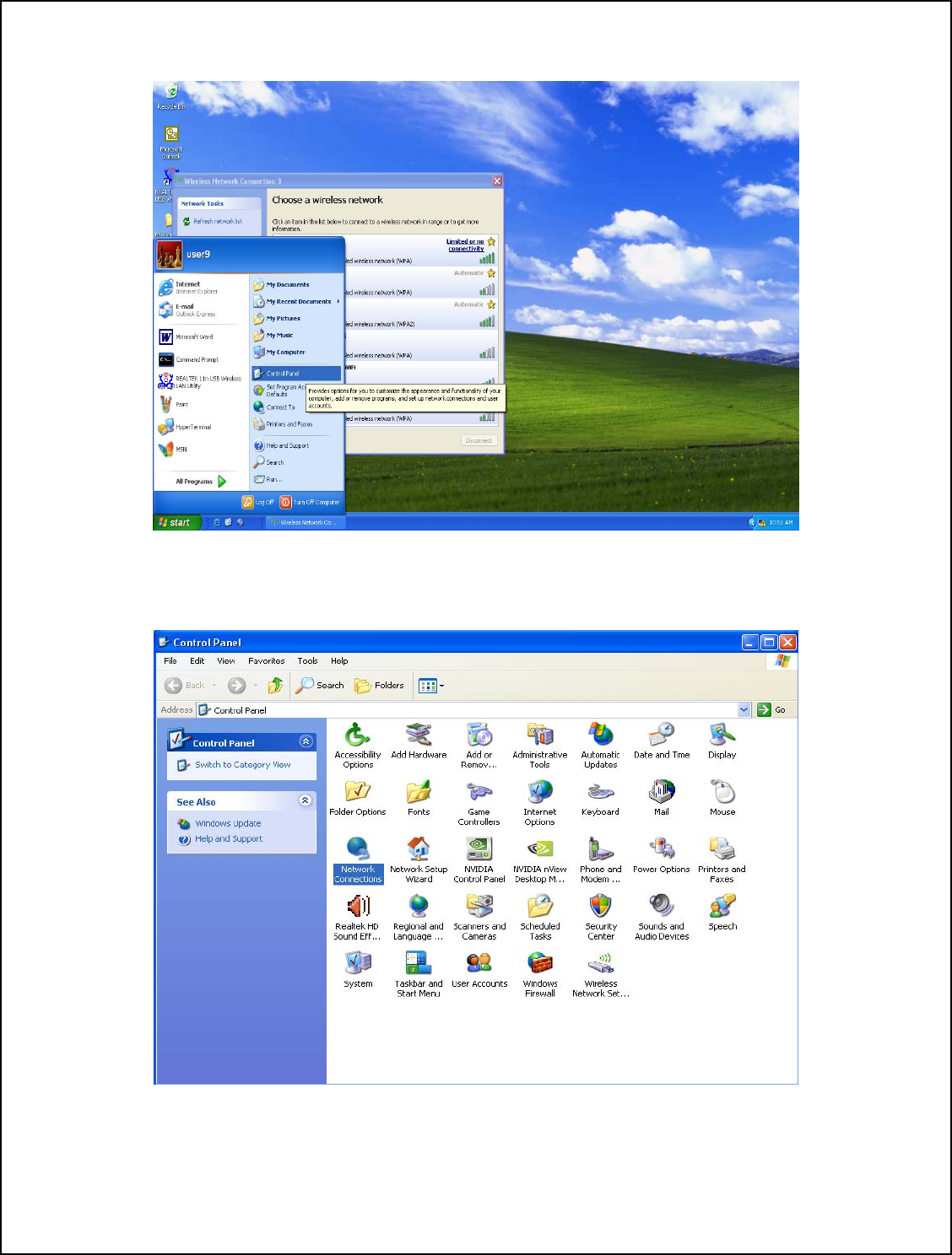
14. Go to Start Menu and select Control Panel.
15. Double click Network Connections icon in Control Panel.
22
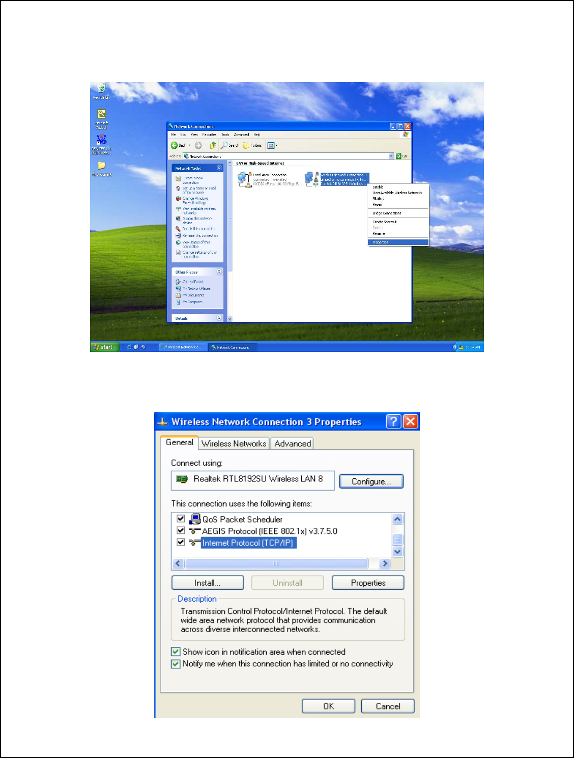
16.0 In Network Connections you will find Wireless Network Connection with “Limited
or no connectivity” status.
16.1 Right click and select Properties.
17. Double click Internet Protocol (TCP/IP) from the drop down list.
23
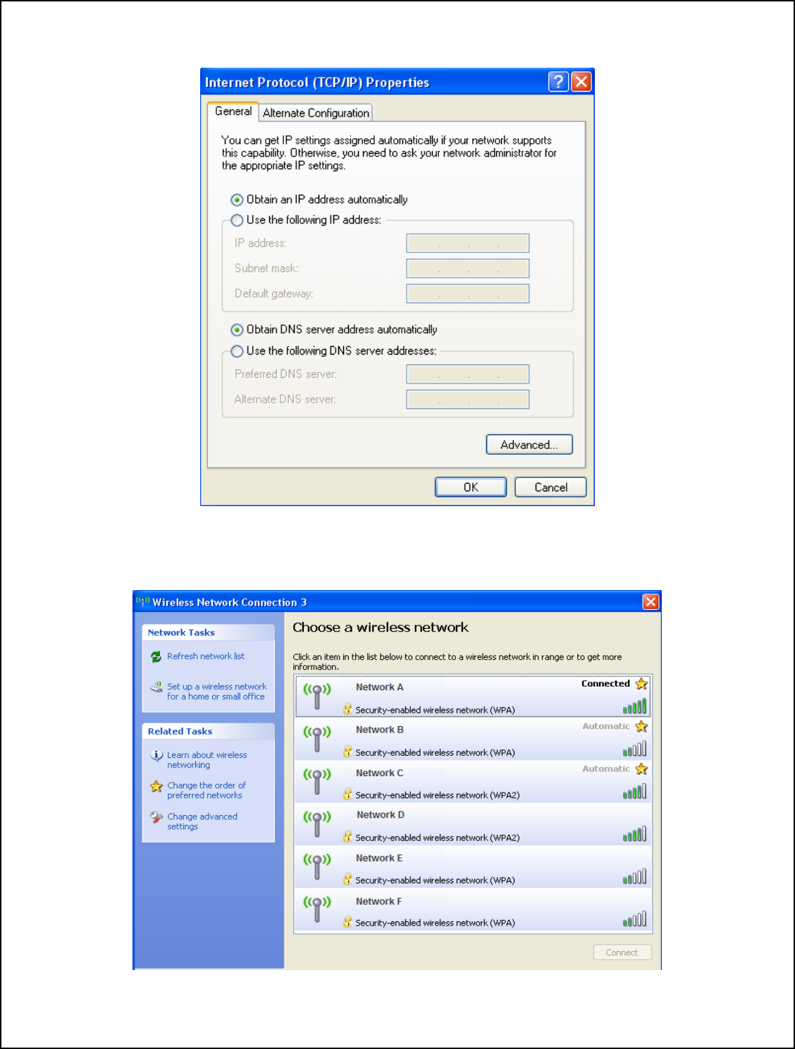
18. Type the IP address then click OK.
19. You are now connected to the wireless network.
24
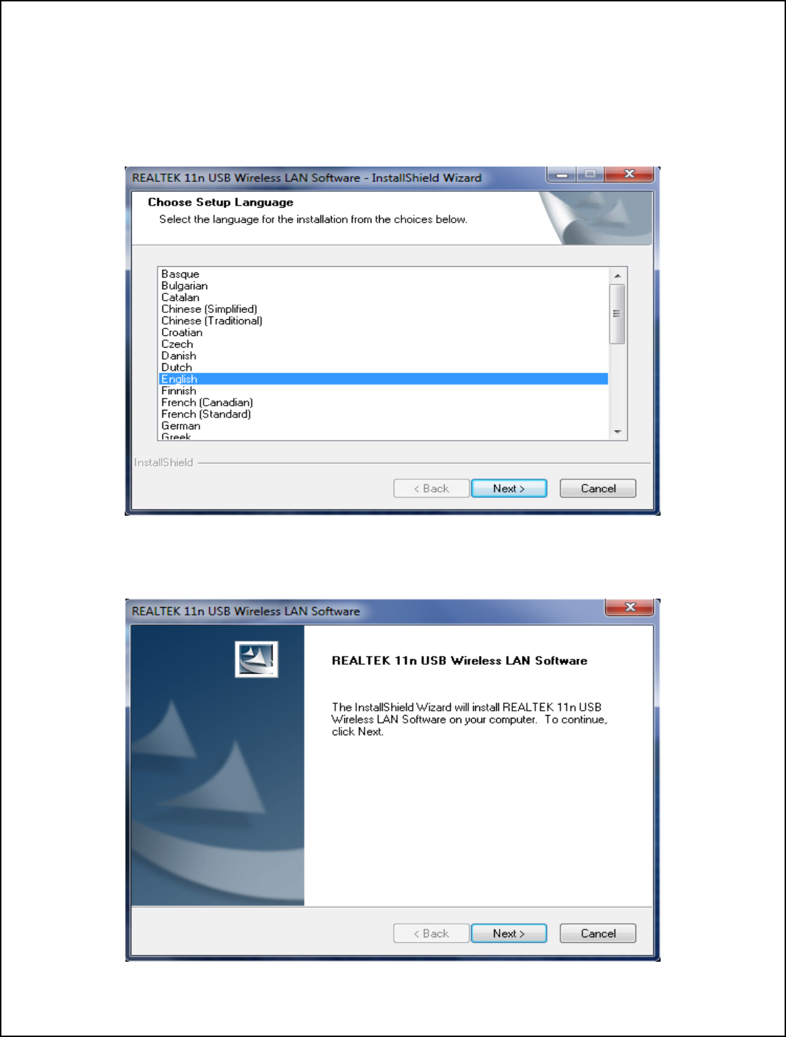
Driver Installation Guide For Windows 7
1.0 Insert the installation disc into CD-ROM.
1.1 Select your language from the Choose Setup Language drop-down list.
1.2 Click NEXT.
2. Click NEXT to continue.
25
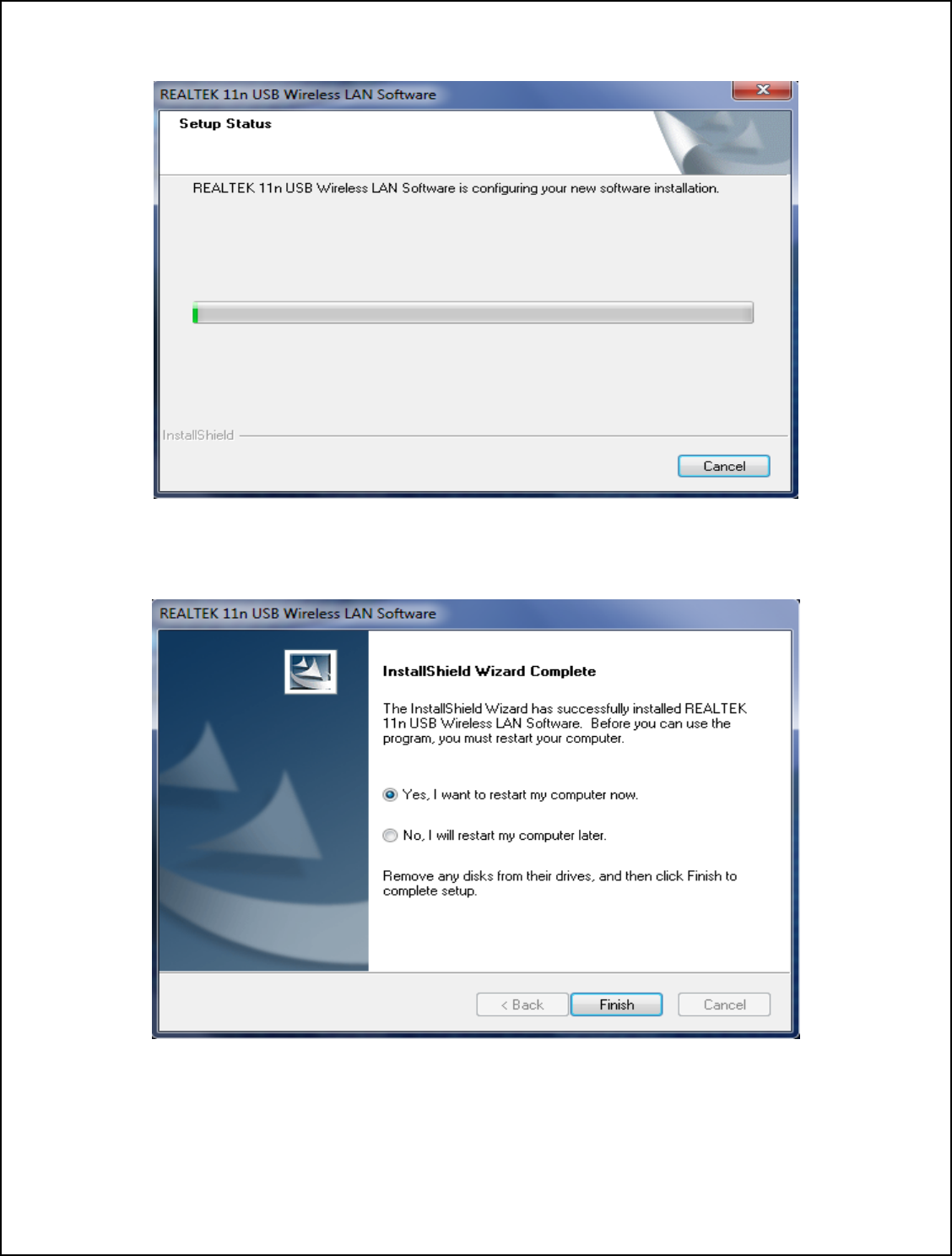
Installing…
3. Click Finish to complete the installation.
26
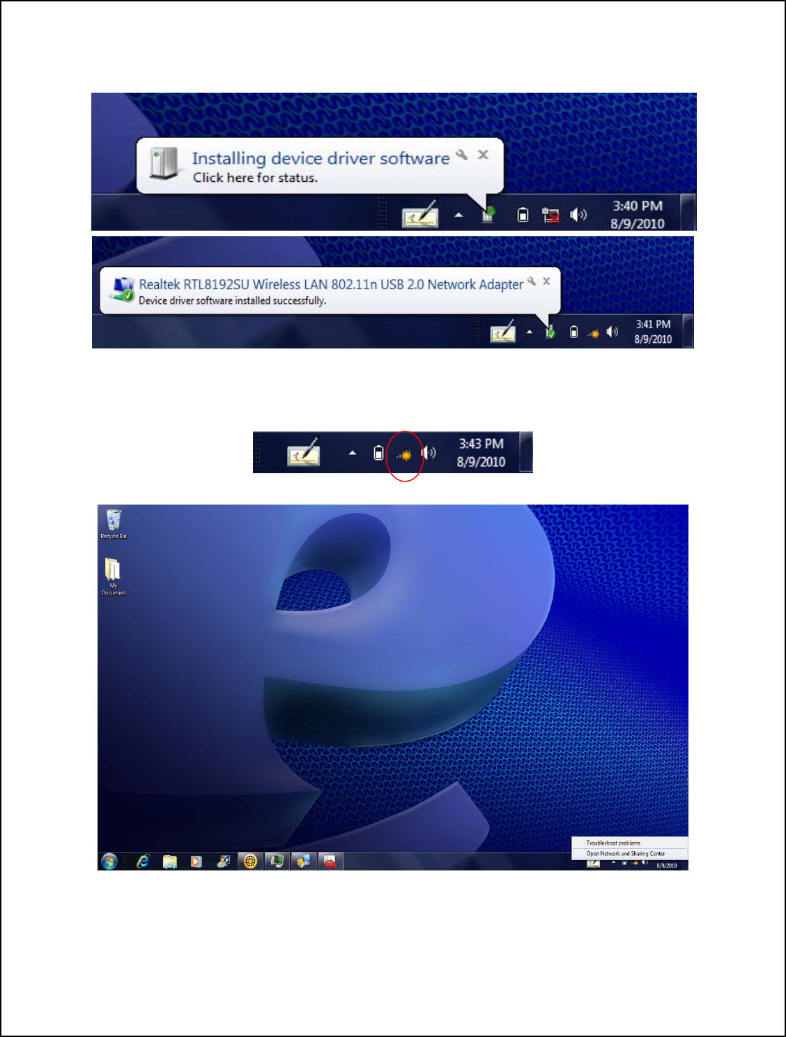
4.0 Plug the device into the USB port.
4.1 Windows will automatically begin the installation for the device.
5.0 Right click the Network Connection icon on the right side of System Tray.
5.1 Select Open Network and Sharing Center.
27
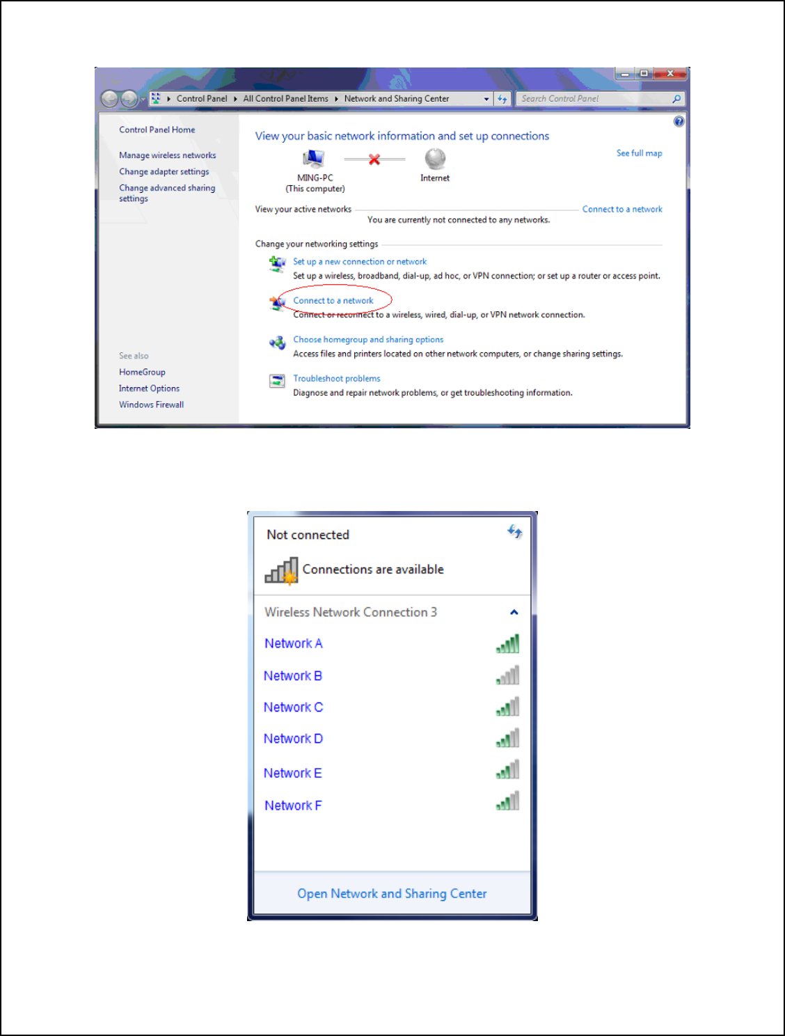
6. Click Connect to a network.
7. Choose a wireless network from the list and double click to connect.
28
8. Enter password then click OK. You are now connected to the wireless network.
29
Driver Installation Guide For Windows Vista
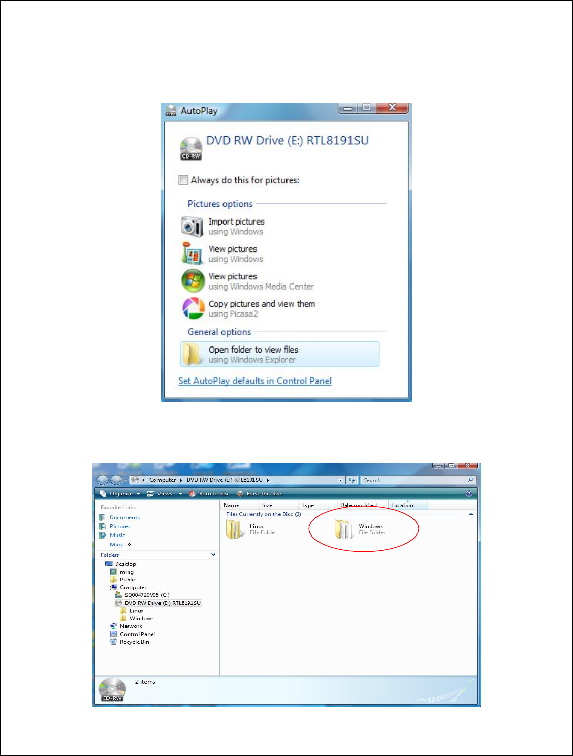
1.0 Insert the installation disc into CD-ROM.
1.1 Select Open folder to view files
2. Double click to open Windows folder.
30
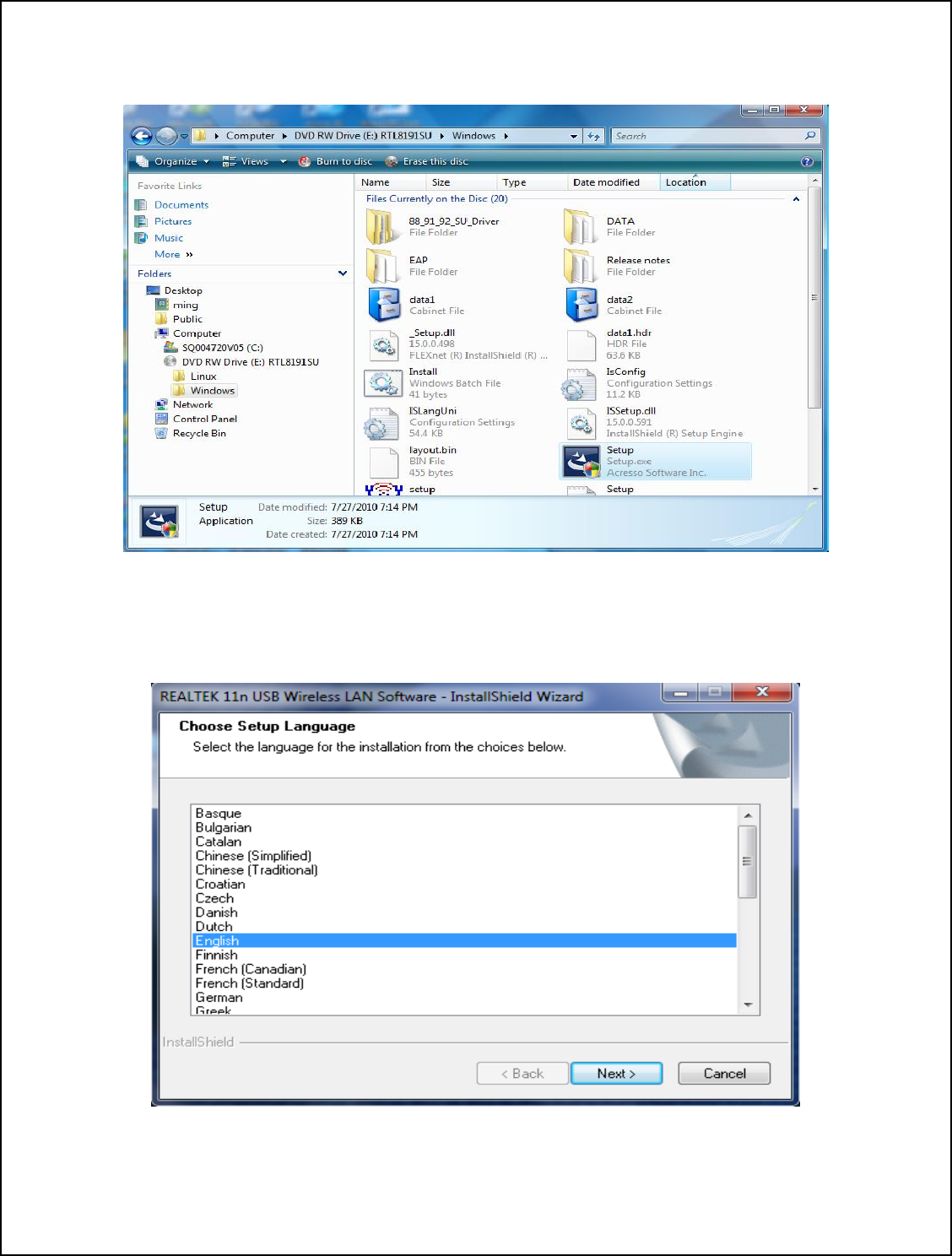
3.0 Double click Setup (Setup.exe) icon to run the setup application.
3.1 Windows will ask your permission to start the program. Click Continue.
4.0 Select your language from the Choose Setup Language drop-down list.
4.1 Click NEXT.
31
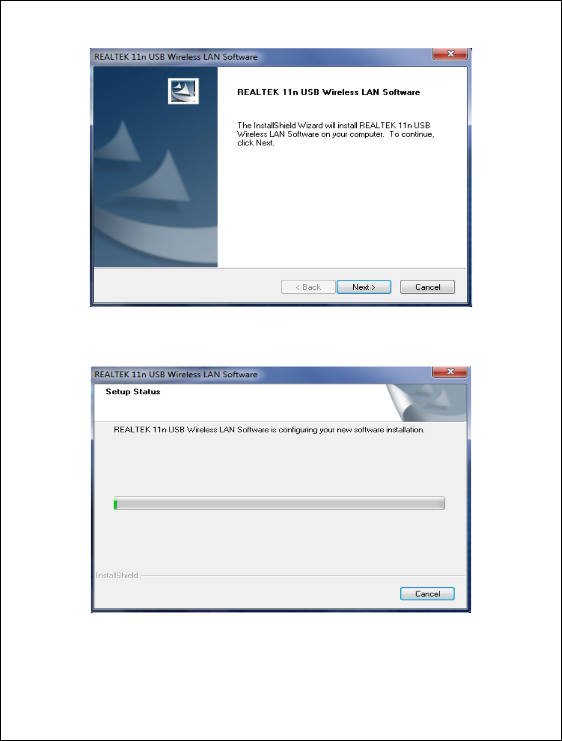
5. Click NEXT to continue.
Installing…
32
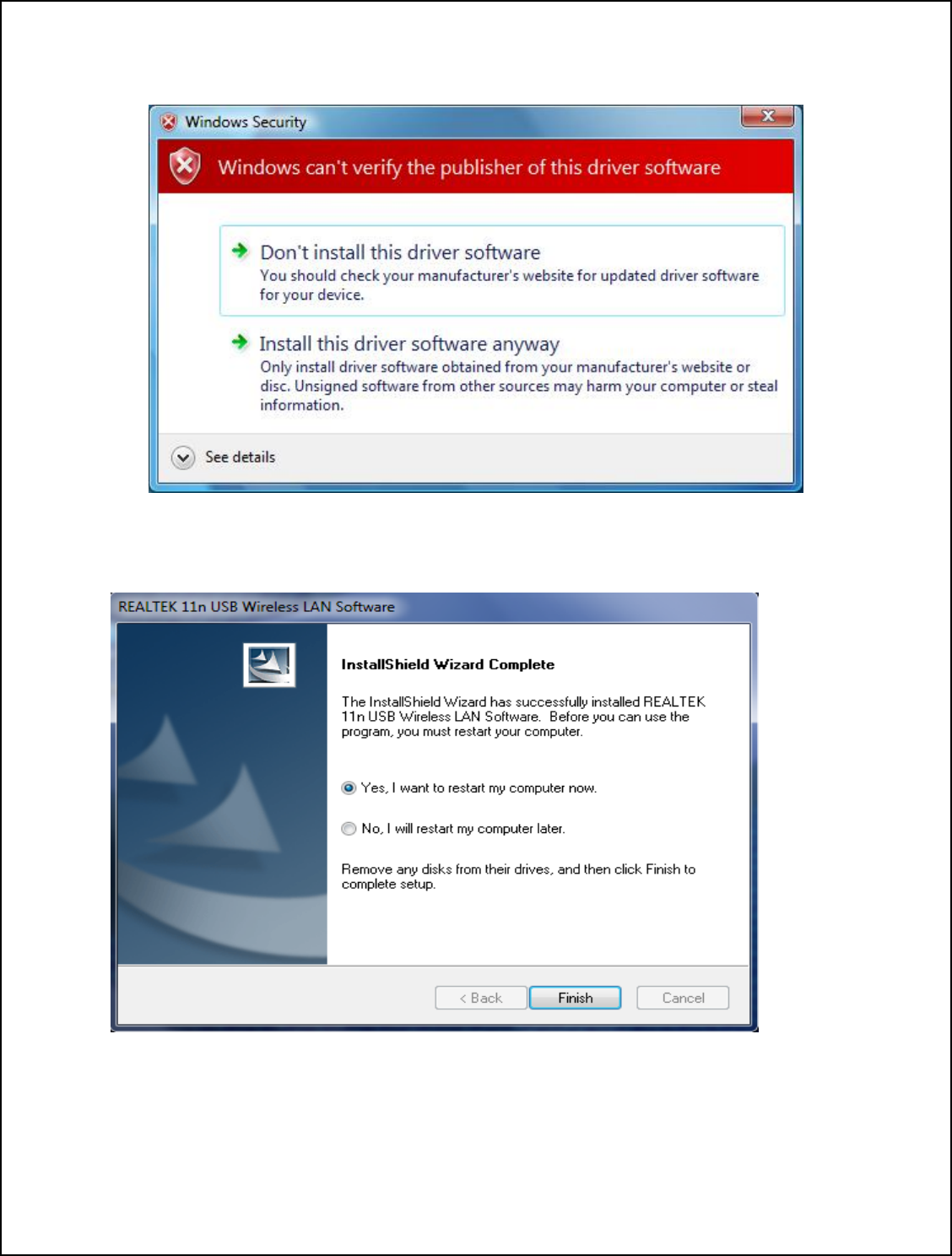
6. If the Windows Security message appears, select Install this driver software anyway
to continue.
7. Click Finish to complete the installation.
33
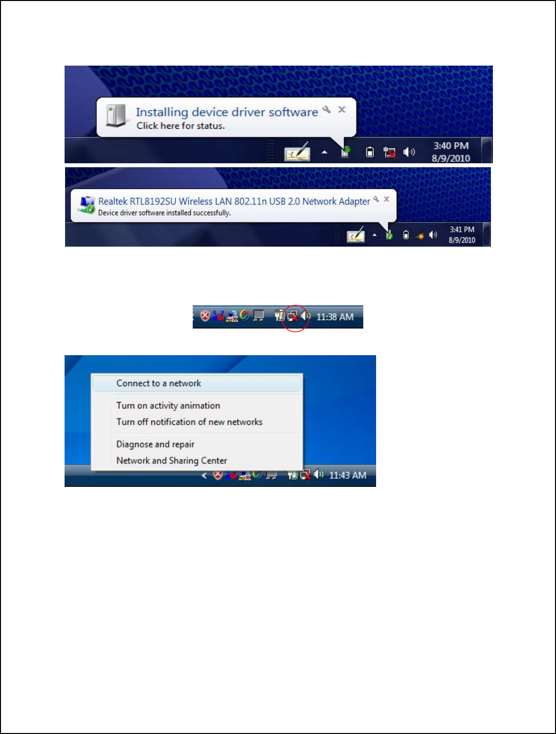
8.0 Plug the device into the USB port.
8.1 Windows will automatically begin the installation for the device.
9.0 Right click the Network Connection icon on the right side of System Tray.
9.1 Select Connect to a network.
34
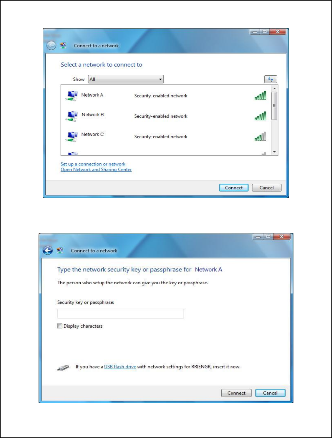
10. Choose a wireless network from the list, then click Connect.
11. Enter password and click Connect. You are now connected to the wireless network.
35

WiFiHU USB Linux Driver Quick Installation Guide
Software Package & Platform requirements:
• The software package contains one WiFiHU Linux driver (source code) that
supports Linux kernel version 2.6, and WiFiHU documents.
• Platform requirements: PC-based Linux platform (i386) and WiFiHU Linux
driver which supports Linux kernel version 2.6.18 through 2.6.35
The following commands have been verified in Ubuntu 9.04 (Kernel version 2.6.28),
Ubuntu 9.10 (Kernel version 2.6.31), Ubuntu 10.04 (Kernel version 2.6.32) and Ubuntu
10.10 (Kernel version 2.6.35).
1. Uncompress driver
>tar zxvf WiFiHU_linux_driver_021611.tar.gz
2. Change to driver directory
>cd rtl8712_8188_8191_8192SU_usb_linux_v2.6.6.0.20101111
3. Make WiFiHU USB driver module
>make
4. Clean the operation environment
>sudo ./clean
5. Insert WiFiHU module
>sudo rmmod 8712u.ko
>sudo insmod 8712u.ko
6. Use ifconfig to set up wireless LAN operation
36

Limited Warranty
Warranty Coverage and Duration
Radicom Research, Inc. (“RRI”) warrants to the original purchaser its RRI-manufactured
products (“Product”) against defects in material and workmanship under normal use and
service for a period of one year from the date of delivery.
During the applicable warranty period, at no charge, RRI will, at its option, either repair,
replace or refund the purchase price of this Product, provided it is returned in accordance
with the terms of this warranty to RRI. Repair, at the option of RRI, may include the
replacement of parts, boards or other components with functionally equivalent
reconditioned or new parts, boards or other components. Replaced parts, boards or other
components are warranted for the balance of the original applicable warranty period. All
replaced items shall become the property of RRI.
RRI MAKES NO GUARANTEE OR WARRANTY THAT THE PRODUCT WILL
PREVENT OCCURRENCES, OR THE CONSEQUENCES THEREOF, WHICH THE
PRODUCT IS DESIGNED TO DETECT.
This expressed limited warranty is extended by RRI to the original end-user purchaser
only, and is not assignable or transferable to any other party. This is the complete
warranty for the Product manufactured by RRI, and RRI assumes no obligation or
liability for additions or modifications to this warranty. In no case does RRI warrant the
installation, maintenance or service of the Product.
RRI is not responsible in any way for any ancillary equipment not furnished by RRI that
is attached to or used in connection with the Product, or for operation of the Product with
any ancillary equipment, and all such equipment is expressly excluded from this
warranty. Because of wide variations in topographical and atmospheric conditions,
which may require availability of repeater stations or of particular radio frequencies, RRI
assumes no liability for range, coverage or suitability of the Product for any particular
application. Buyer acknowledges that RRI does not know a particular purpose for which
buyer wants the Product, and that buyer is not relying on RRI’s skill and judgment to
select or furnish suitable goods.
What this Warranty does NOT Cover:
(a) Defects or damage resulting from use of the Product in other than its normal and
customary manner.
(b) Defects or damage from misuse, accident or neglect.
(c) Defects of damage from improper testing, operation, maintenance, installation,
alteration, modification or adjustment.
37

(d) Disassembly or repair of the Product in such a manner as to adversely affect
performance or prevent adequate inspection and testing to verify any warranty claim.
(e) Any Product that has had its serial number or date code removed or made illegible.
How to Receive Warranty Service:
To obtain warranty service, contact RRI by phone (408) 383 9006 for RMA Department
or email to rma@radi.com for an RMA (Return Merchandise Authorization) number.
Deliver or send the Product, transportation and insurance prepaid to RRI, with the RMA
number clearly marked on the outside of the package.
General Provision
This warranty sets forth the full extent of RRI’s responsibilities regarding the Product.
Repair, replacement or refund of the purchase price, at RRI’s option, is the exclusive
remedy.
THIS WARRANTY IS GIVEN IN LIEU OF ALL OTHER EXPRESSED
WARRANTIES. ANY APPLICABLE IMPLIED WARRANTIES, INCLUDING
WITHOUT LIMITATION THE IMPLIED WARRANTY OF MERCHANTABILITY,
ARE LIMITED TO THE DURATION OF THIS LIMITED WARRANTY. TO THE
FULLEST EXTENT PERMITTED BY LAW, RRI DISCLAIMS ANY LIABILITY
FOR DAMAGES IN EXCESS OF THE PURCHASE PRICE OF THE PRODUCT, FOR
ANY LOSS OF USE, LOSS OF TIME, INCONVENIENCE, COMMERCIAL LOSS,
LOST PROFITS OR SAVING OR OTHER INCIDENTAL, SPECIAL OR
CONSEQUENTIAL DAMAGES ARISING OUT OF THE USE OR INABILITY TO
USE OR FAILURE OF SUCH PRODUCT.
38


For IC
3.2.1 Labelling Requirements for the Host device. The host device shall be properly labelled to identify the modules within the
host device. The Industry Canada certification label of a module shall be clearly visible at all times when installed in the host
device, otherwise the host device must be labelled to display the Industry Canada certification number of the module, preceded
by the words “Contains transmitter module”, or the word “Contains”, or similar wording expressing the same meaning, as
follows: Contains transmitter module IC: 2377A-WIFIHUA and 2377A-WIFIHUC2NE where 2377A-WIFIHUA and
2377A-WIFIHUC2NE are the module’s certification number. The applicant for equipment certification of the module shall
provide with each unit of the module either a label such as described above, or an explanation and instructions to the user as to
the host device labelling requirements.
For FCC
This device is intended only for OEM integrators under the following conditions:
1) The antenna must be installed such that 20 cm is maintained between the antenna and users. For laptop installations,
the antenna must be installed to ensure that the proper spacing is maintained in the event the users places the device
in their lap during use (i.e. positioning of antennas must be placed in the upper portion of the LCD panel only to
ensure 20 cm will be maintained if the user places the device in their lap for use) and
2) The transmitter module may not be co-located with any other transmitter or antenna.
As long as the 2 conditions above are met, further transmitter testing will not be required. However, the OEM
integrator is still responsible for testing their end-product for any additional compliance requirements required with
this module installed (for example, digital device emissions, PC peripheral requirements, etc.).
IMPORTANT NOTE: In the event that these conditions can not be met (for example certain laptop
configurations or co-location with another transmitter), then the FCC authorization is no longer considered
valid and the FCC ID can not be used on the final product. In these circumstances, the OEM integrator will
be responsible for re-evaluating the end product (including the transmitter) and obtaining a separate FCC
authorization.
End Product Labeling
This transmitter module is authorized only for use in devices where the antenna may be installed such that 20
cm may be maintained between the antenna and users (for example access points, routers, wireless ASDL
modems, certain laptop configurations, and similar equipment). The final end product must be labeled in a
visible area with the following: "Contains TX FCC ID: K7T-WIFIHU-A and K7T-WIFIHU-C-2-NE".
RF Exposure Manual Information That Must be Included
The users manual for end users must include the following information in a prominent location "IMPORTANT
NOTE: To comply with FCC RF exposure compliance requirements, the antenna used for this transmitter
must be installed to provide a separation distance of at least 20 cm from all persons and must not be co-located
or operating in conjunction with any other antenna or transmitter."
Additional Information That Must be Provided to OEM Integrators
The end user should NOT be provided any instructions on how to remove or install the device.