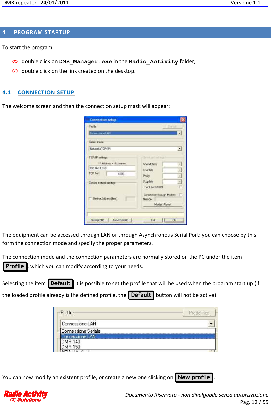
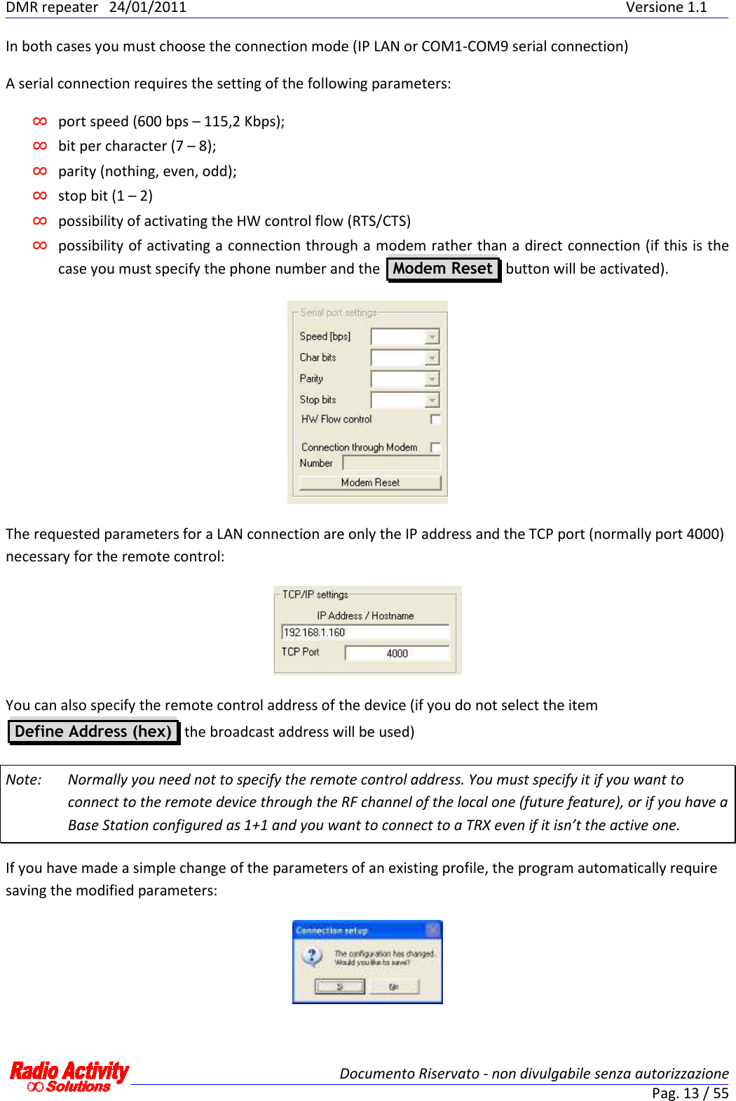
Radio Activity srl RA-160 DMR REPEATER – VHF BASE STATION User Manual ENB30 DMR Manager 1v1
Radio Activity srl DMR REPEATER – VHF BASE STATION ENB30 DMR Manager 1v1
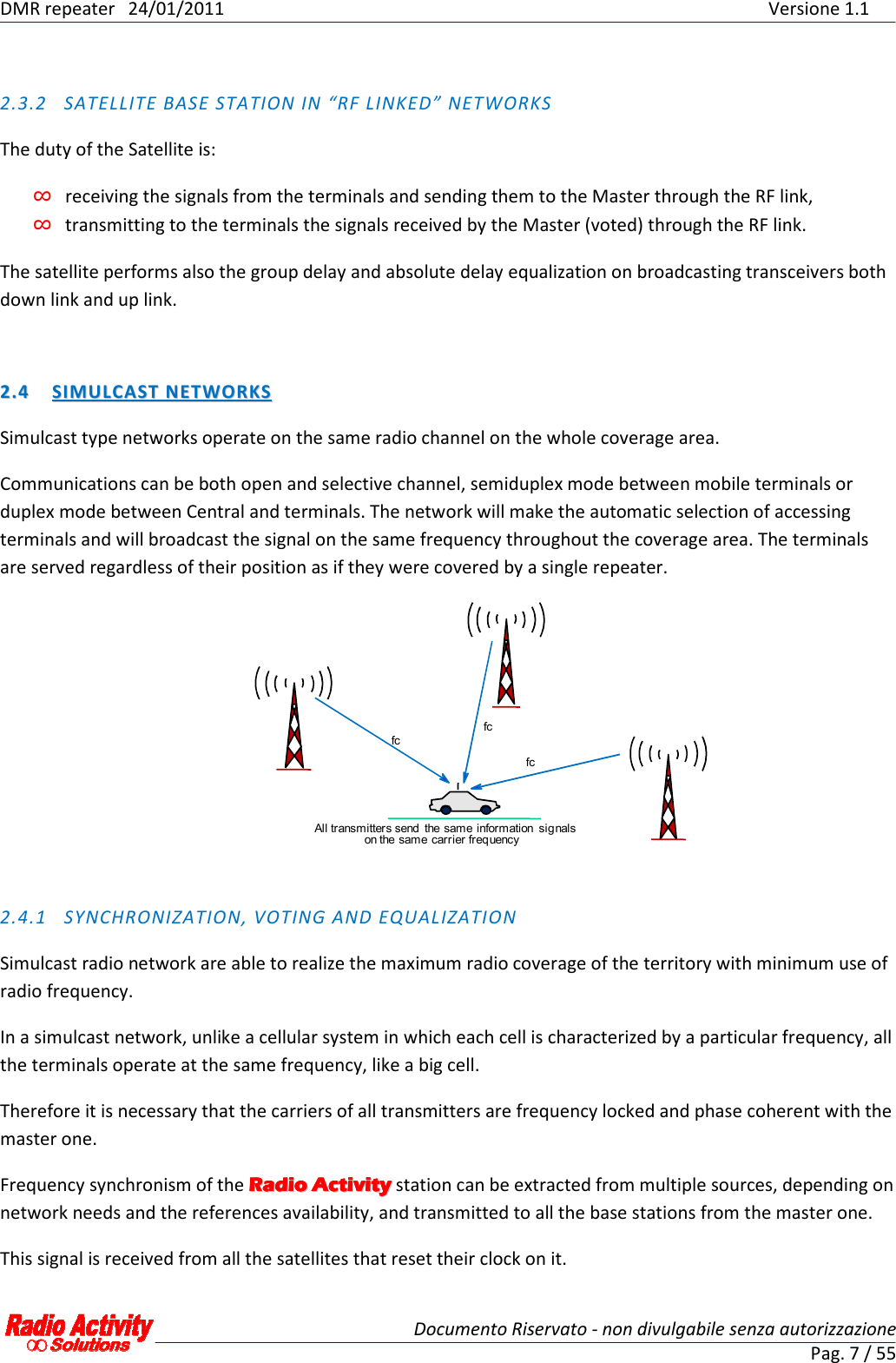
UserManual.wiki
>
Radio Activity srl
>
RA-160 User Manual
>
user manual
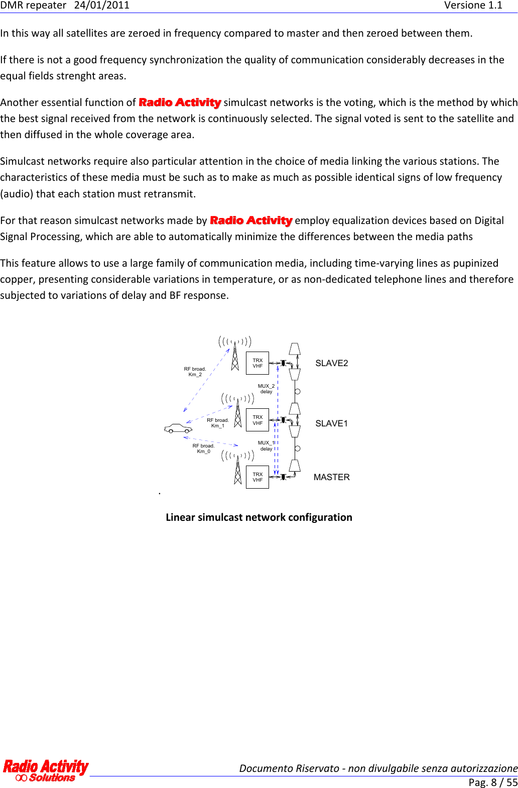
Contents
1.
use manual
2.
user manual
user manual
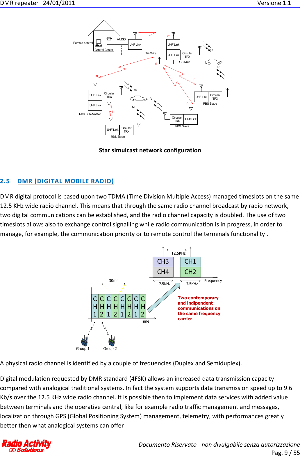
Navigation menu
Upload a User Manual
Namespaces
Wiki Guide
HTML
PDF
Info
Views
User Manual
Discussion / Help
Navigation
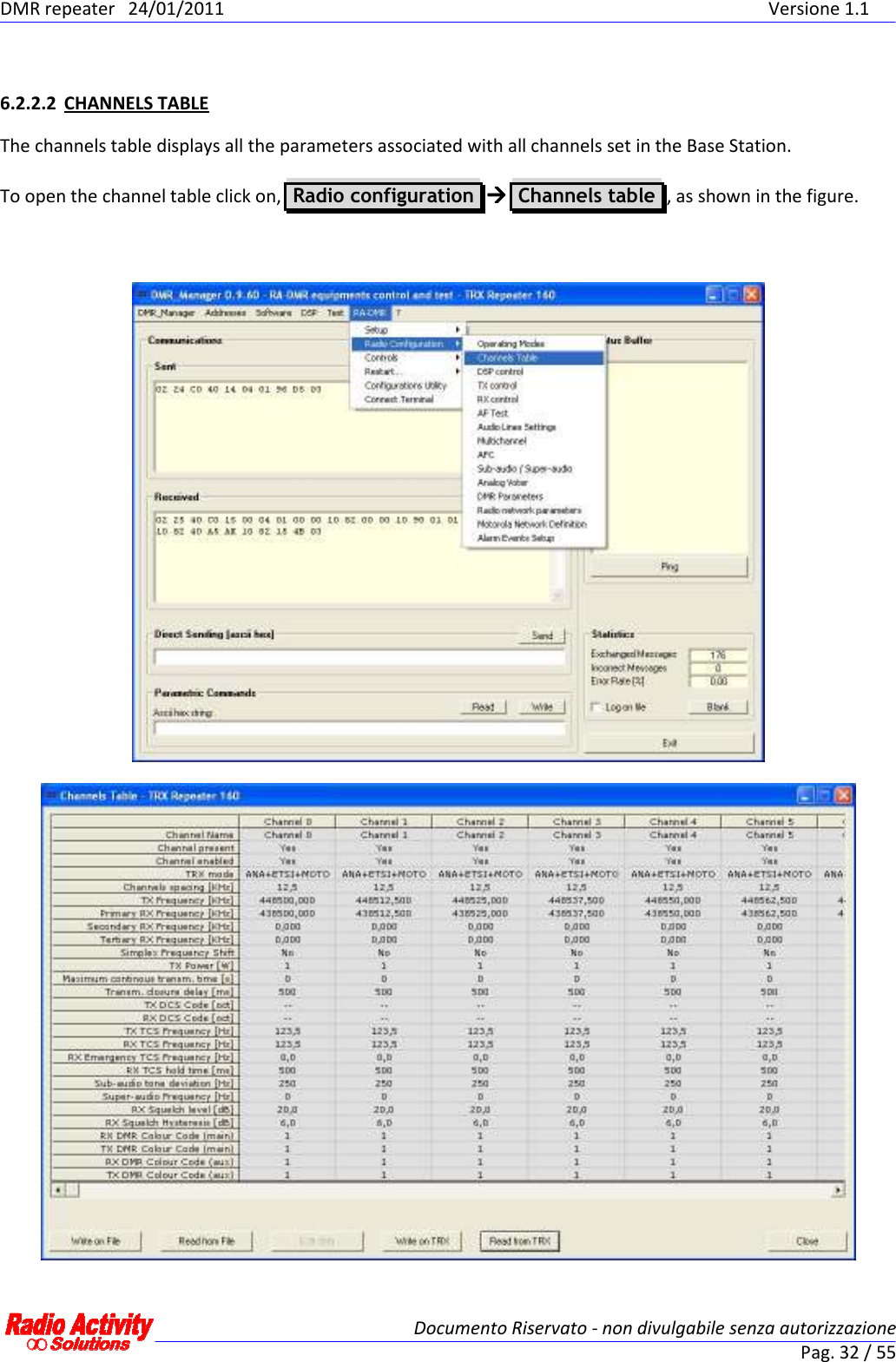
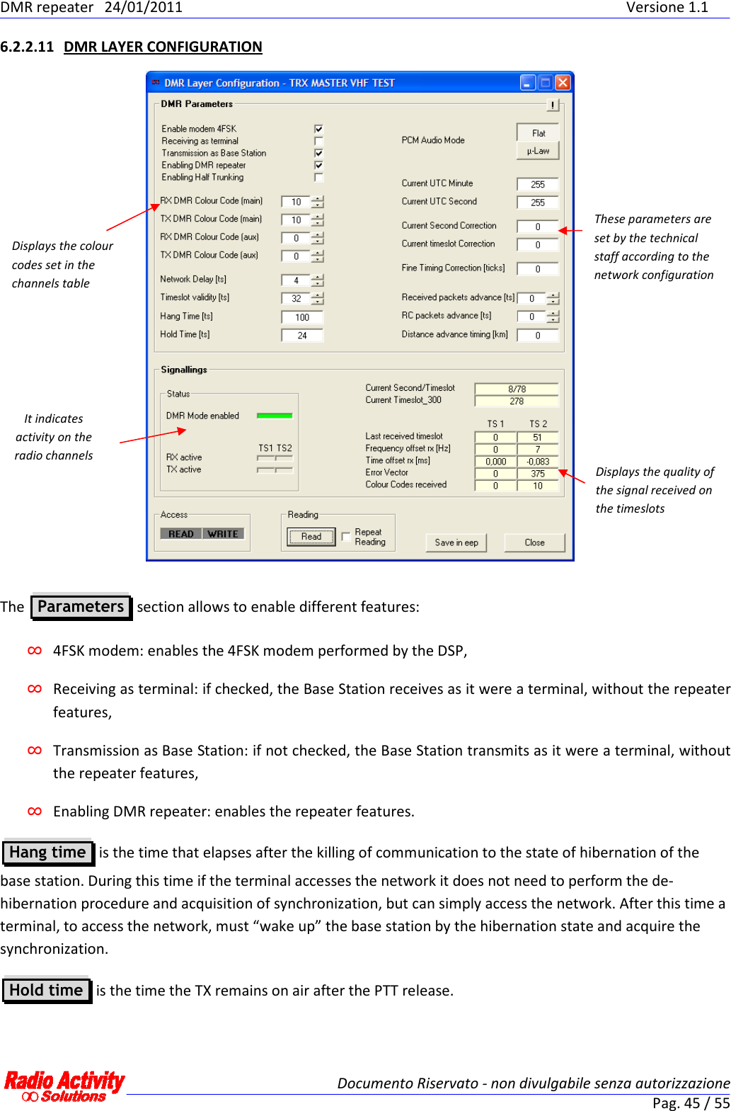
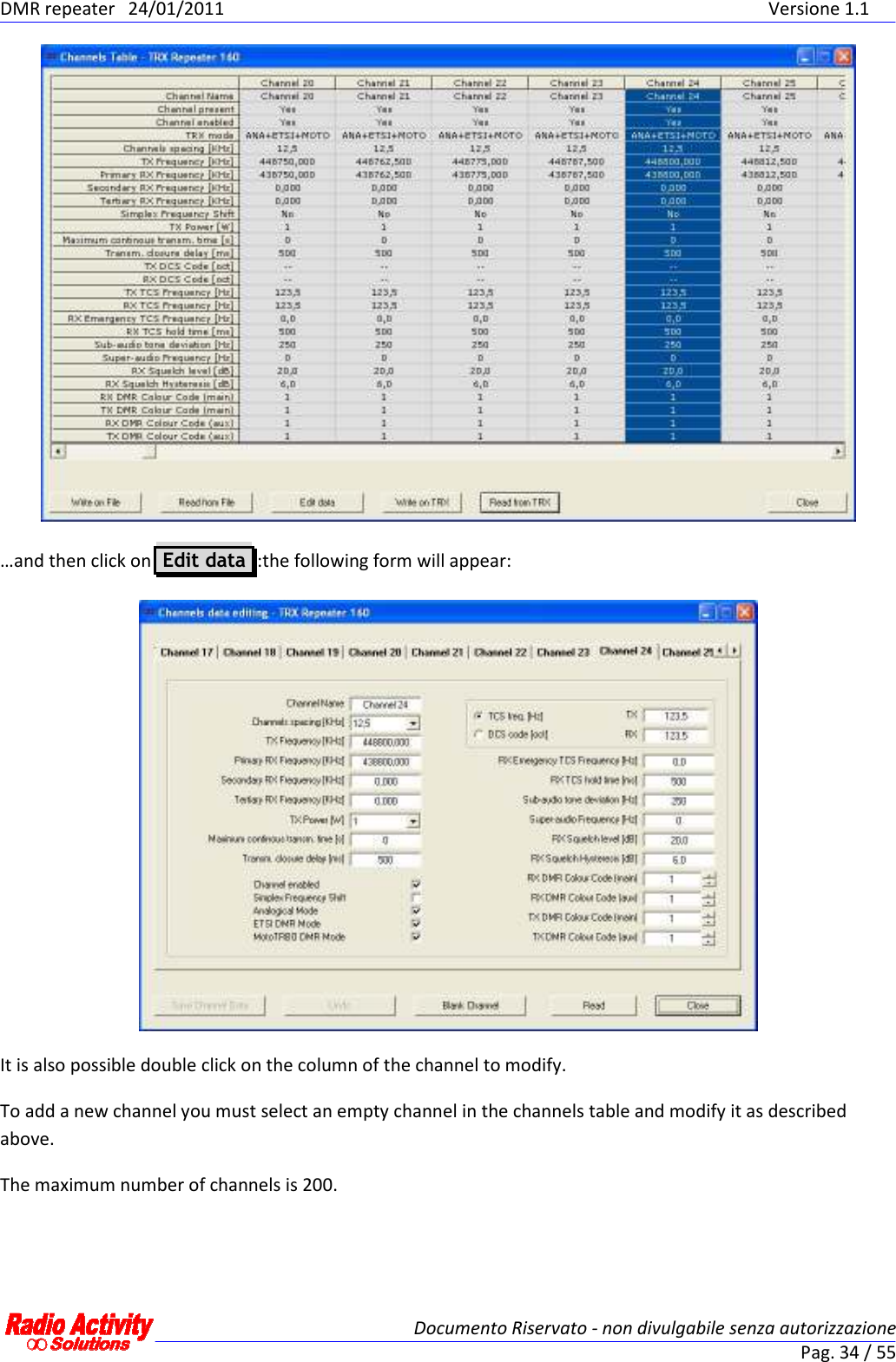
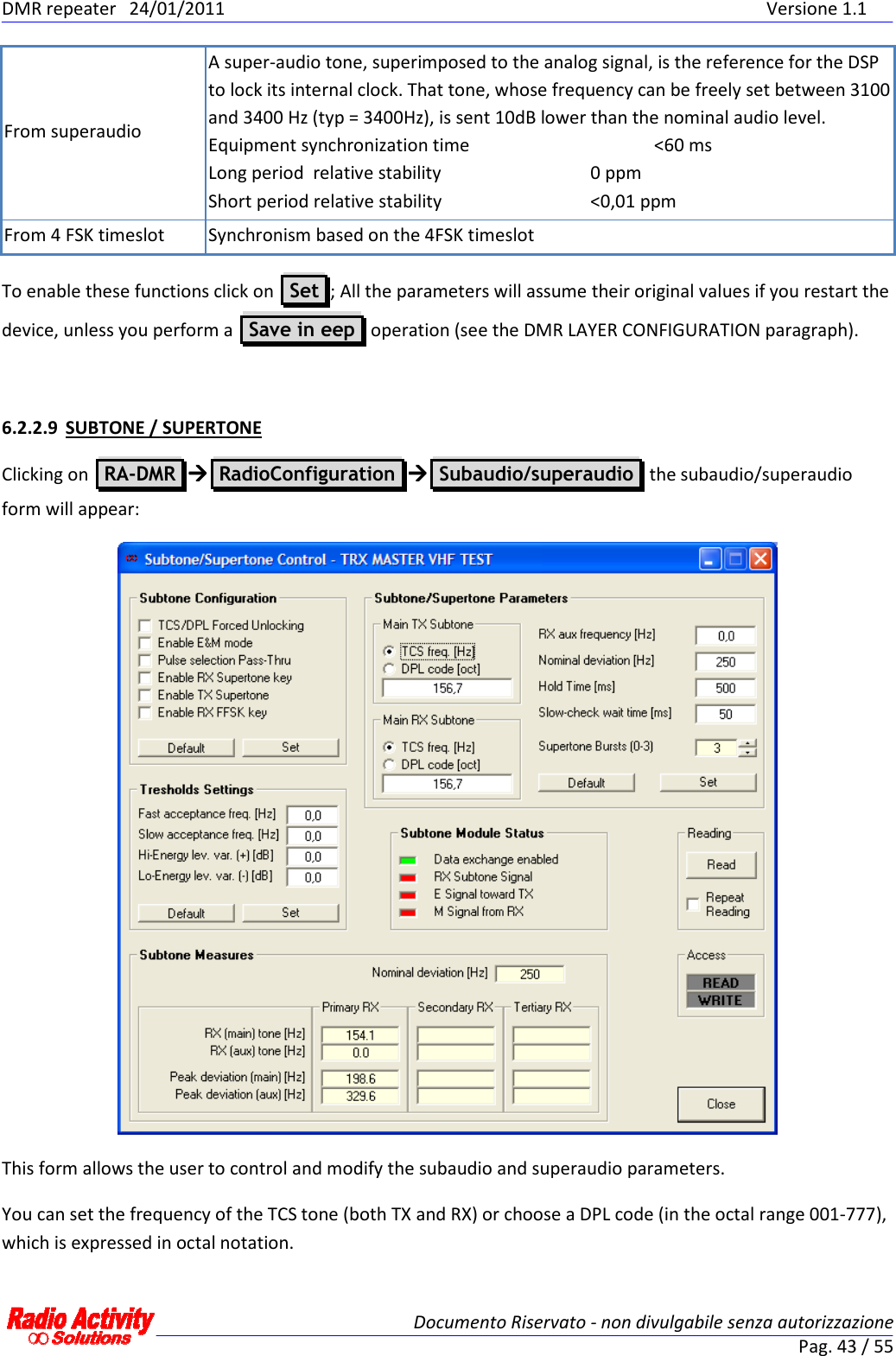
![DMR repeater 24/01/2011 Versione 1.1 Documento Riservato - non divulgabile senza autorizzazione Pag. 33 / 55 The parameters of the channels table are reported in the following table. Channel name Channel present Presence of the channel Channel enabled Enabling of the channel TRX Mode Indicates all of the possible transmission mode allowed: Analog, compatible with ETSI standard, compatible with Motorola terminals Channel spacing [KHz] Allows to choose the channel spacing: 25KHz, 20KHz, 12.5KHz, 10KHz TX Frequency [KHz] Transmission frequency Primary RX frequency [KHz] Receiving frequency of the primary receiver Secondary RX frequency [KHz] Receiving frequency of the secondary receiver Tertiary RX frequency [KHz] Receiving frequency of the tertiary receiver Simplex frequency shift If set, when the TX is active, the RX frequency is shifted to avoid interferences. This is meaningful only for simplex operating mode. TX power [W] Transmission power Maximum continuous transmission [s] Maximum time allowed for continuous transmission (if 0, this option is not active) Transmission closure delay [ms] Time before carrier off after the end of the communication TX DCS code [oct] Allows to choose a DCS code to transmit (Octal notation) RX DCS code [oct] Allows to choose a DCS code to receive (Octal notation) TX TCS frequency [Hz] Allows to set a subaudio tone to transmit RX TCS frequency [Hz] Allows to set a subaudio tone to receive RX emergency TCS frequency [Hz] Allows to set an emergency subaudio tone to receive RX TCS hold time [ms] Time before TCS off after the end of the communication Subaudio tone deviation Subaudio deviation Superaudio frequency [Hz] Superaudio frequency RX squelch level [dB] Allows to set a squelch opening level RX squelch Hysteresis [db] Difference between squelch opening and closure levels DMR colour code RX Main RX colour code DMR colour code TX Main TX colour code DMR colour code RX aux RX emergency colour code DMR colour code TX aux TX emergency colour code To modify the channel parameters click on the column of the channel to modify…](https://usermanual.wiki/Radio-Activity-srl/RA-160.user-manual/User-Guide-1420979-Page-33.png)
![DMR repeater 24/01/2011 Versione 1.1 Documento Riservato - non divulgabile senza autorizzazione Pag. 44 / 55 To enable these functions click on Set ; All the parameters will assume their original values if you restart the device, unless you perform a Save in eep operation (see the DMR LAYER CONFIGURATION paragraph). 6.2.2.10 ANALOG VOTER Clicking on RA-DMR RadioConfiguration Analogical voter the following form will appear: This form allows the user to set the analogical voter inputs (in the section Voter parameters ), In the Voter parameters section you can: ∞ choose the signal sources for the analogical voting and the related setting time, ∞ set the hold time for the voted source (that is the minimum time before source changing), ∞ set the switch time (that is the minimum time between source changing after hold time expiration), ∞ set the signal hysteresis (that is the signal threshold for a valid candidate source). You can set these parameters specifying the numbers in the section on the right: Initial setting time [ms] is the searching time for the best signal initially, Hold time [ms] is the time the voted source is maintained. Switch time [ms] is the time step after which a different input can be voted as the “best”, Hysteresys [dB] is a threshold: if another signal is Hysteresys [dB] better than the currently voted one, that signal become the new voted one. To enable these functions click on Set ; All the parameters will assume their original values if you restart the device, unless you perform a Save in eep operation (see the DMR LAYER CONFIGURATION paragraph).](https://usermanual.wiki/Radio-Activity-srl/RA-160.user-manual/User-Guide-1420979-Page-44.png)