Radio Activity srl RA-160 DMR REPEATER – VHF BASE STATION User Manual ENB30 DMR Manager 1v1
Radio Activity srl DMR REPEATER – VHF BASE STATION ENB30 DMR Manager 1v1
Contents
- 1. use manual
- 2. user manual
user manual

DMR
DIGITAL MOBILE RADIO ASSOCIATION
Radio Activity S.r.l.
Sede: Via Ponte Nuovo, 8 - 20128 Milano – email: radio.activity@fastwebnet.it - www.radioactivity-tlc.com
Tel. 02.36514205 - FAX/Voicebox 1782242408 - Registrazione CCIAA Milano N° 1728248 - P.I./C.F. 04135130963
D
DM
MR
R_
_M
Ma
an
na
ag
ge
er
r
O
Op
pe
er
ra
at
ti
in
ng
g
M
Ma
an
nu
ua
al
l
V
Ve
er
rs
si
io
on
n
1
1v
v1
1

DMR repeater 24/01/2011 Versione 1.1
Documento Riservato - non divulgabile senza autorizzazione
Pag. 2 / 55
Index
1 INTRODUCTION........................................................................................................................4
2 CONCEPTS OVERVIEW ..............................................................................................................4
2.1
TRX ARCHITECTURE....................................................................................................................... 4
2.2
RADIO ACTIVITY DMR REPEATER AND UPGRADEABILITY TO SIMULCAST NETWORK........................ 6
2.3
NETWORK..................................................................................................................................... 6
2.3.1
MASTER BASE STATION IN “RF LINKED” NETWORKS........................................................................ 6
2.3.2
SATELLITE BASE STATION IN “RF LINKED” NETWORKS ..................................................................... 7
2.4
SIMULCAST NETWORKS................................................................................................................. 7
2.4.1
SYNCHRONIZATION, VOTING AND EQUALIZATION .......................................................................... 7
2.5
DMR (DIGITAL MOBILE RADIO) ...................................................................................................... 9
2.5.1
ALARM MESSAGES .......................................................................................................................... 10
3 INSTALLATION........................................................................................................................10
3.1
SYSTEM REQUIREMENTS ............................................................................................................. 10
3.2
INSTALLATION ON THE PC ........................................................................................................... 10
3.2.1
INSTALLATION ON WINDOWS 2000
OR WINDOWS XP
OPERATING SYSTEMS...........................11
3.2.2
INSTALLATION ON WINDOWS VISTA OPERATING SYSTEM ......................................................... 11
3.3
CREATING LINK TO DESKTOP ....................................................................................................... 11
3.4
UNINSTALLATION FROM WINDOWS 2000 OR WINDOWS XP ........................................................ 11
3.5
UNINSTALLATION ON WINDOWS VISTA OPERATING SYSTEM....................................................... 11
4 PROGRAM STARTUP...............................................................................................................12
4.1
CONNECTION SETUP ................................................................................................................... 12
4.2
REMOTE CONTROL CONNECTION LOST ........................................................................................ 14
5 MAIN MENU WINDOW...........................................................................................................15
5.1
DMR MANAGER .......................................................................................................................... 16
5.2
ADDRESSES................................................................................................................................. 16
5.3
SOFTWARE.................................................................................................................................. 17
5.4
DSP............................................................................................................................................. 18
5.5
TEST ........................................................................................................................................... 18
5.6
RA DMR...................................................................................................................................... 19

DMR repeater 24/01/2011 Versione 1.1
Documento Riservato - non divulgabile senza autorizzazione
Pag. 3 / 55
6 MENU DETAILS.......................................................................................................................20
6.1
SOFTWARE MENU....................................................................................................................... 20
6.1.1
VERSIONS ........................................................................................................................................ 20
6.1.2
DOWNLOAD .................................................................................................................................... 21
6.2
RA-DMR MENU ........................................................................................................................... 23
6.2.1
SETUP .............................................................................................................................................. 23
6.2.1.1
DATE AND TIME ....................................................................................................................... 24
6.2.1.2
E-DSP CONFIGURATION ........................................................................................................... 24
6.2.1.3
GPS/GPRS CONFIGURATION ....................................................................................................25
6.2.1.4
OPERATING PARAMETERS ....................................................................................................... 26
6.2.1.5
STARTUP STATUS ..................................................................................................................... 26
6.2.2
RADIO CONFIGURATION .................................................................................................................28
6.2.2.1
TRX OPERATING MODES.......................................................................................................... 29
6.2.2.2
CHANNELS TABLE..................................................................................................................... 32
6.2.2.3
TX CONTROL............................................................................................................................. 35
6.2.2.4
RX CONTROL ............................................................................................................................ 36
6.2.2.5
TEST AF.....................................................................................................................................37
6.2.2.6
AUDIO LINES CONFIGURATION (FOR ANALOG USE OR FOR SYNCHRONIZATION AIM ONLY) 38
6.2.2.7
MULTICHANNEL ....................................................................................................................... 39
6.2.2.8
AFC - AUTOMATIC FREQUENCY CONTROL .............................................................................. 41
6.2.2.9
SUBTONE / SUPERTONE........................................................................................................... 43
6.2.2.10
ANALOG VOTER .......................................................................................................................44
6.2.2.11
DMR LAYER CONFIGURATION.................................................................................................. 45
6.2.2.12
DMR OPERATING MODES ........................................................................................................ 46
6.2.2.13
DMR SERVICES DEFINITION ..................................................................................................... 47
6.2.2.14
ALARM EVENTS SETUP............................................................................................................. 48
6.2.3
CONTROLS. ...................................................................................................................................... 50
6.2.3.1
I/O STATUS............................................................................................................................... 51
6.2.3.2
RADIO CONTROL ...................................................................................................................... 51
6.2.3.3
CALIBRATIONS RESULTS........................................................................................................... 53
6.2.3.4
AUDIO LINES CONTROL............................................................................................................ 54
6.2.4
RESTART .......................................................................................................................................... 54
6.2.5
CONFIGURATIONS UTILITY..............................................................................................................55
6.2.6
CONNECT TERMINAL....................................................................................................................... 55

DMR repeater 24/01/2011 Versione 1.1
Documento Riservato - non divulgabile senza autorizzazione
Pag. 4 / 55
1 INTRODUCTION
This document illustrates the applications and how to use the Radio Activity DMR base stations management
software.
Radio Activity DMR base stations can support a lot of applications and the management software is designed
with forms for reading the parameters that can change depending on the particular application.
For that reason the forms shown in this document may be different from the ones in use or they could not
appear in your application if the specific functionality is not enabled.
Some forms may be incomplete because it is a work in progress, please notify us errors or inconsistencies.
2 CONCEPTS OVERVIEW
The Radio Activity DMR Base Station can include several TRX (master and slaves), where TRX refers to a
transmitter, one or many receivers, DSP, IO board and a power supply.
Radio Activity DMR Base Stations allow many different applications: they can work like a single repeater or in a
radio network made of different repeaters linked together in different way such as Ethernet link, RF link.
2
2.
.1
1
T
TR
RX
X
A
AR
RC
CH
HI
IT
TE
EC
CT
TU
UR
RE
E
The core of “physical layer” of the system is a unit which via software performs every function of signal
processing into radio station.
So, it is not necessary to add boards (like synchronizers, phase and amplitude equalizers, signal decoders,
modem, etc.) because the functions can be implemented by routines which can be freely matched, down-
loaded and with superior performance.
Communication and control functions of module are entrusted to a microprocessor which manages
communications with external world and with other equipment modules. The microprocessor is based on
LINUX operative system; it can manage a LAN ethernet 10/100 interface both for copper line and for optical
fiber links, it is equipped with 4 serial ports to manage radio modules, GPS, auxiliary devices, external hosts; it
is equipped with a Real Time Clock with tampon battery; it controls an embedded PLL to synchronize the
entire station upon an internal (VCTCXO 0.5 ppm) or external temporal reference. DSP module is equipped
with a synchronous serial port according RS485 standard levels, which can be programmed up to 16Mbit/s and
can be used to interconnect together more transceiver or additional equipments.
Main performed functions are the following:

DMR repeater 24/01/2011 Versione 1.1
Documento Riservato - non divulgabile senza autorizzazione
Pag. 5 / 55
∞ Frequency self-tuning device
∞ Deviation self-calibration device
∞ Analogical and digital demodulation
∞ RF circuits testing
∞ Phase modulator calibration
∞ RF output power control
∞ Low frequency lines management
∞ DMR protocols management
∞ Digital signals processing
∞ Management, conditioning and routing of traffic and remote control signals from and towards
external world
Receiver can be supplied as single or double for space diversity reception. Main and diversity channels are
completely independent and coherent (sharing the same local oscillators) and they are designed according to
an heterodyne structure, with vectorial conversion to base-band.
Channel standard bandwidth is 12.5 KHz, but the receiver is prepared to accept also a settable channel
bandwidth of 25 KHz, 20 KHz, 10 KHz (with double funnel option) for special applications.
Receiver module is managed by a microcontroller unit whose program is hosted inside internal e2prom flash
memory to lower parasitic emissions. This FW can be loaded through serial connection. The microcontroller, in
addition to managing internal function of the unit, transfers measured parameters to the control unit through
115.2 Kb/s serial line.
The board is realized with surface mounting components (SMD) to maximally reduce dimensions.
On the frontal panel 2 LEDs are placed for monitoring internal PLLs lock status.
Transmitter module is realized with surface mounting components (SMD) and it is housed in a shielded, 8TE
box for 220mm Eurocards, with an heatsink mounted on side, with a thermal resistance of about 1.2°K/W. The
unit can be extracted from the front side of the rack. On the frontal panel two LEDs are placed to monitor the
transmitter status.
Base-band functions, equalizing, limiting, low-pass filtering end eventual emphasis functions are performed by
the DSP unit, which provides also for nominal and maximum deviation calibration by looping modulator with
receiver.
Modulator is digital vector, then the synthesized signal by local oscillator implements the frequency shifting of
the signal which has been directly modulated in base-band by DSP unit and transferred to transmitter through
its I and Q components.
The amplifier is realized by three cascaded stages and RF output power regulation (between 1 and 25W) is
implemented by controlling the stages. Power amplifier works in C class and ensures a very high efficiency,
lowering the needed power from supply system and lowering the thermal dissipation inside the cabinet. Direct
and reflected output power are measured by a directional coupler. Power control circuit acts in a closed loop
and keeps constant the total power at MOSFET drain. Inside the module a thermal sensor is hosted and it is
directly connected to the internal microcontroller which enables the command for air forced cooling fan of the
cabinet if the temperature rises over 85°C. Anyway, if reflected power or mosfet temperature exceeds
protection threshold, regulation circuit will lower output power up to safe levels for transmitter.

DMR repeater 24/01/2011 Versione 1.1
Documento Riservato - non divulgabile senza autorizzazione
Pag. 6 / 55
The current flowing into final amplifier transistor is continuously monitored by microcontroller to verify the
correct functioning and to reveal any efficiency degradation.
The module is equipped with an harmonic filter to lower spurious emissions under required levels by existing
regulations.
2
2.
.2
2
R
RA
AD
DI
IO
O
A
AC
CT
TI
IV
VI
IT
TY
Y
D
DM
MR
R
R
RE
EP
PE
EA
AT
TE
ER
R
A
AN
ND
D
U
UP
PG
GR
RA
AD
DE
EA
AB
BI
IL
LI
IT
TY
Y
T
TO
O
S
SI
IM
MU
UL
LC
CA
AS
ST
T
N
NE
ET
TW
WO
OR
RK
K
Radio Activity DMR repeater is designed to be modular from both HW and SW point of view, to maximize its
flexibility and minimize costs, physical dimensions, consumptions.
Basic model already has all the characteristics to work as a double standard repeater with all the features of
analogical and digital service. It can be equipped with double receiver to counteract fading effects through
diversity space reception. It is set to host communication and synchronization embedded devices to make the
network expandable to a multi-frequency or single-frequency multi-site system, with different types of links,
operating with different transportation system topology, like microwave, UHF, optical fibers, IP connections.
Privileged communication interface is Ethernet standard type, compatible with more diffused technology. This
interface supports not only voice and data digital traffic, but also remote control management, which for
Radio Activity equipment is very powerful: it is possible to have a complete monitor system of equipment
status, it is possible to modify each parameter, to down-load each SW and configuration, launch self-test and
calibration functions, to perform specific tests through internal embedded function generators and software
analyzers of the station. For analogical voice traffic instead, a 2/4 wire and criteria line interface is available.
Remote control service can be performed through an Ethernet connection pre-existing in the site, or through
GPRS modem which can be integrated into the station, or through the radio channel and another Radio
Activity station.
Fully modular structure allows to best configure the radio equipment, by adding and/or changing the required
HW and SW functional blocks, to work as simple repeater, multi-frequency multi-site repeater, single-
frequency multi-site repeater.
2
2.
.3
3
N
NE
ET
TW
WO
OR
RK
K
It is possible to configure the network in many different ways, with different kinds of links (Ethernet, RF,
Optical fibers)
2.3.1 MASTER BASE STATION IN “RF LINKED” NETWORKS
The master base station is equipped with a “voting system”, which select the “best” signal among all the
signals received by the Satellites and the local receiver(s).
Besides this the master sends the digital synchronization towards the satellites and, in the case of Base
Stations “RF linked” equalizes the absolute and group delay due to the RF channel.

DMR repeater 24/01/2011 Versione 1.1
Documento Riservato - non divulgabile senza autorizzazione
Pag. 7 / 55
2.3.2 SATELLITE BASE STATION IN “RF LINKED” NETWORKS
The duty of the Satellite is:
∞ receiving the signals from the terminals and sending them to the Master through the RF link,
∞ transmitting to the terminals the signals received by the Master (voted) through the RF link.
The satellite performs also the group delay and absolute delay equalization on broadcasting transceivers both
down link and up link.
2
2.
.4
4
S
SI
IM
MU
UL
LC
CA
AS
ST
T
N
NE
ET
TW
WO
OR
RK
KS
S
Simulcast type networks operate on the same radio channel on the whole coverage area.
Communications can be both open and selective channel, semiduplex mode between mobile terminals or
duplex mode between Central and terminals. The network will make the automatic selection of accessing
terminals and will broadcast the signal on the same frequency throughout the coverage area. The terminals
are served regardless of their position as if they were covered by a single repeater.
All transmitters send the same information signals
on the same carrier frequency
fc
fc
fc
2.4.1 SYNCHRONIZATION, VOTING AND EQUALIZATION
Simulcast radio network are able to realize the maximum radio coverage of the territory with minimum use of
radio frequency.
In a simulcast network, unlike a cellular system in which each cell is characterized by a particular frequency, all
the terminals operate at the same frequency, like a big cell.
Therefore it is necessary that the carriers of all transmitters are frequency locked and phase coherent with the
master one.
Frequency synchronism of the R
RR
R
R
RR
Ra
aa
a
a
aa
ad
dd
d
d
dd
di
ii
i
i
ii
io
oo
o
o
oo
o
A
AA
A
A
AA
Ac
cc
c
c
cc
ct
tt
t
t
tt
ti
ii
i
i
ii
iv
vv
v
v
vv
vi
ii
i
i
ii
it
tt
t
t
tt
ty
yy
y
y
yy
y station can be extracted from multiple sources, depending on
network needs and the references availability, and transmitted to all the base stations from the master one.
This signal is received from all the satellites that reset their clock on it.

DMR repeater 24/01/2011 Versione 1.1
Documento Riservato - non divulgabile senza autorizzazione
Pag. 8 / 55
In this way all satellites are zeroed in frequency compared to master and then zeroed between them.
If there is not a good frequency synchronization the quality of communication considerably decreases in the
equal fields strenght areas.
Another essential function of R
RR
R
R
RR
Ra
aa
a
a
aa
ad
dd
d
d
dd
di
ii
i
i
ii
io
oo
o
o
oo
o
A
AA
A
A
AA
Ac
cc
c
c
cc
ct
tt
t
t
tt
ti
ii
i
i
ii
iv
vv
v
v
vv
vi
ii
i
i
ii
it
tt
t
t
tt
ty
yy
y
y
yy
y simulcast networks is the voting, which is the method by which
the best signal received from the network is continuously selected. The signal voted is sent to the satellite and
then diffused in the whole coverage area.
Simulcast networks require also particular attention in the choice of media linking the various stations. The
characteristics of these media must be such as to make as much as possible identical signs of low frequency
(audio) that each station must retransmit.
For that reason simulcast networks made by R
RR
R
R
RR
Ra
aa
a
a
aa
ad
dd
d
d
dd
di
ii
i
i
ii
io
oo
o
o
oo
o
A
AA
A
A
AA
Ac
cc
c
c
cc
ct
tt
t
t
tt
ti
ii
i
i
ii
iv
vv
v
v
vv
vi
ii
i
i
ii
it
tt
t
t
tt
ty
yy
y
y
yy
y employ equalization devices based on Digital
Signal Processing, which are able to automatically minimize the differences between the media paths
This feature allows to use a large family of communication media, including time-varying lines as pupinized
copper, presenting considerable variations in temperature, or as non-dedicated telephone lines and therefore
subjected to variations of delay and BF response.
.
TRX
VHF
TRX
VHF
TRX
VHF
RF broad.
Km_2
RF broad.
Km_1
RF broad.
Km_0
MUX_1
delay
MUX_2
delay
SLAVE2
SLAVE1
MASTER
Linear simulcast network configuration

DMR repeater 24/01/2011 Versione 1.1
Documento Riservato - non divulgabile senza autorizzazione
Pag. 9 / 55
UHF Link Circular
TRX
UHF Link
Remote control
AUDIO
Control Center
UHF Link
UHF Link Circular
TRX
Circular
TRX UHF Link
Circular
TRX
UHF Link
fc
fc
fc
fc
2/4 Wire
RBS Slave
RBS Slave
RBS Main
fl
fl
fl
fl
UHF Link
RBS Slave
UHF Link Circular
TRX
fc
RBS Sub-Master
Star simulcast network configuration
2
2.
.5
5
D
DM
MR
R
(
(D
DI
IG
GI
IT
TA
AL
L
M
MO
OB
BI
IL
LE
E
R
RA
AD
DI
IO
O)
)
DMR digital protocol is based upon two TDMA (Time Division Multiple Access) managed timeslots on the same
12.5 KHz wide radio channel. This means that through the same radio channel broadcast by radio network,
two digital communications can be established, and the radio channel capacity is doubled. The use of two
timeslots allows also to exchange control signalling while radio communication is in progress, in order to
manage, for example, the communication priority or to remote control the terminals functionality .
C
H
1
C
H
2
C
H
1
C
H
2
C
H
1
C
H
2
C
H
1
C
H
2
Group 1 Group 2
Time
CH2
Frequency
CH1
7.5KHz
CH4
CH3
7.5KHz
12.5KHz
Two contemporary
and indipendent
communications on
the same frequency
carrier
30ms
A physical radio channel is identified by a couple of frequencies (Duplex and Semiduplex).
Digital modulation requested by DMR standard (4FSK) allows an increased data transmission capacity
compared with analogical traditional systems. In fact the system supports data transmission speed up to 9.6
Kb/s over the 12.5 KHz wide radio channel. It is possible then to implement data services with added value
between terminals and the operative central, like for example radio traffic management and messages,
localization through GPS (Global Positioning System) management, telemetry, with performances greatly
better then what analogical systems can offer

DMR repeater 24/01/2011 Versione 1.1
Documento Riservato - non divulgabile senza autorizzazione
Pag. 10 / 55
2.5.1 ALARM MESSAGES
This feature of Radio Activity DMR Base Stations allows the user to bind some events with the sending of short
text messages: when a certain event occurs, the user will receive the text message on the designed mobile
terminal and a warning message when the problem is resolved (see Alarm Events Setup).
3 INSTALLATION
To use the DMR-Manager properly and to the correct management of the Radio Activity DMR Base Stations it
is necessary to have a PC and a LAN connection.
3
3.
.1
1
S
SY
YS
ST
TE
EM
M
R
RE
EQ
QU
UI
IR
RE
EM
ME
EN
NT
TS
S
The following operating systems are supported:
∞ Windows 2000
®
∞ Windows XP
®
∞ Windows Vista™ 32 bit
Not supported:
∞ Windows NT
®
∞ Windows 9x
∞ Windows ME
∞ 64 bit Windows versions
The processor must fit the following requirements:
Operating system:................Microsoft Windows 2000
®
SP4 or Windows XP
®
SP2 or Windows Vista™ 32 bit.
Processor: ............................Intel Pentium
®
or compatible.
Speed ...................................700 MHz (Minimum).
Memory: ..............................64 MB (Minimum).
Disk space: ...........................~30 MB.
I/O: .......................................LAN and/or serial port.
3
3.
.2
2
I
IN
NS
ST
TA
AL
LL
LA
AT
TI
IO
ON
N
O
ON
N
T
TH
HE
E
P
PC
C
DMR_Manager is normally distributed on a CD ROM. To install the program insert the CD ROM in the CD
reader and then run the installation script, depending on the particular operating system in use.

DMR repeater 24/01/2011 Versione 1.1
Documento Riservato - non divulgabile senza autorizzazione
Pag. 11 / 55
3.2.1 INSTALLATION ON WINDOWS 2000
OR WINDOWS XP
OPERATING SYSTEMS
To install DMR_Manager double click the file:
∞ Setup2000.bat for Windows 2000 operating systems;
∞ SetupXP.bat for Windows XP operating systems.
The program creates the folder Radio_Activity in the program folder (normally C:\Program Files)
3.2.2 INSTALLATION ON WINDOWS VISTA
OPERATING SYSTEM
Run SetupVista.bat as Administrator (click with the right button on SetupVista.bat, then click on
Run as Administrator)
The folder Radio_Activity will be created on C:\.
3
3.
.3
3
C
CR
RE
EA
AT
TI
IN
NG
G
L
LI
IN
NK
K
T
TO
O
D
DE
ES
SK
KT
TO
OP
P
It is possible to create a link on the desktop of the file DMR_Manager.exe, from Radio_Activity folder
:click with the right button on DMR_Manager.exe, then click on Send to, click on Desktop.
3
3.
.4
4
U
UN
NI
IN
NS
ST
TA
AL
LL
LA
AT
TI
IO
ON
N
F
FR
RO
OM
M
W
WI
IN
ND
DO
OW
WS
S
2
20
00
00
0
O
OR
R
W
WI
IN
ND
DO
OW
WS
S
X
XP
P
Double click on Unistall.bat
3
3.
.5
5
U
UN
NI
IN
NS
ST
TA
AL
LL
LA
AT
TI
IO
ON
N
O
ON
N
W
WI
IN
ND
DO
OW
WS
S
V
VI
IS
ST
TA
A
O
OP
PE
ER
RA
AT
TI
IN
NG
G
S
SY
YS
ST
TE
EM
M
Run Unistall.bat as Administrator (click with the right button on Unistall.bat, then click on Run
as Administrator).

DMR repeater 24/01/2011 Versione 1.1
Documento Riservato - non divulgabile senza autorizzazione
Pag. 12 / 55
4 PROGRAM STARTUP
To start the program:
∞ double click on DMR_Manager.exe in the Radio_Activity folder;
∞ double click on the link created on the desktop.
4
4.
.1
1
C
CO
ON
NN
NE
EC
CT
TI
IO
ON
N
S
SE
ET
TU
UP
P
The welcome screen and then the connection setup mask will appear:
The equipment can be accessed through LAN or through Asynchronous Serial Port: you can choose by this
form the connection mode and specify the proper parameters.
The connection mode and the connection parameters are normally stored on the PC under the item
Profile , which you can modify according to your needs.
Selecting the item Default it is possible to set the profile that will be used when the program start up (if
the loaded profile already is the defined profile, the Default button will not be active).
You can now modify an existent profile, or create a new one clicking on New profile .

DMR repeater 24/01/2011 Versione 1.1
Documento Riservato - non divulgabile senza autorizzazione
Pag. 13 / 55
In both cases you must choose the connection mode (IP LAN or COM1-COM9 serial connection)
A serial connection requires the setting of the following parameters:
∞ port speed (600 bps – 115,2 Kbps);
∞ bit per character (7 – 8);
∞ parity (nothing, even, odd);
∞ stop bit (1 – 2)
∞ possibility of activating the HW control flow (RTS/CTS)
∞ possibility of activating a connection through a modem rather than a direct connection (if this is the
case you must specify the phone number and the Modem Reset button will be activated).
The requested parameters for a LAN connection are only the IP address and the TCP port (normally port 4000)
necessary for the remote control:
You can also specify the remote control address of the device (if you do not select the item
Define Address (hex) the broadcast address will be used)
Note: Normally you need not to specify the remote control address. You must specify it if you want to
connect to the remote device through the RF channel of the local one (future feature), or if you have a
Base Station configured as 1+1 and you want to connect to a TRX even if it isn’t the active one.
If you have made a simple change of the parameters of an existing profile, the program automatically require
saving the modified parameters:

DMR repeater 24/01/2011 Versione 1.1
Documento Riservato - non divulgabile senza autorizzazione
Pag. 14 / 55
You can save the parameters in the case of permanent change, but it is also possible to continue with the
modified parameters not saved: in this case a subsequent restart of the program will present the original
parameters on the profile you worked with.
When you create a new profile, before going on,you have to save it clicking New profile :
The program will require a name to store the new profile:
Clicking Ok the remote control system will be activated.
Note: Clicking Exit will cause the termination of the program; if you saved a changed profile, or it has
been created a new one, these changes will be maintained.
4
4.
.2
2
R
RE
EM
MO
OT
TE
E
C
CO
ON
NT
TR
RO
OL
L
C
CO
ON
NN
NE
EC
CT
TI
IO
ON
N
L
LO
OS
ST
T
If the DMR_Manager close the logical connection, two cases are possible:
∞ If there is a serial bus connection, the device just do not react to the solicitations;
∞ If there is a LAN connection, the lost of the connection will be reported by a specific form:

DMR repeater 24/01/2011 Versione 1.1
Documento Riservato - non divulgabile senza autorizzazione
Pag. 15 / 55
5 MAIN MENU WINDOW
Once the logical connection is established, the main menu window will appear:
Many of the functions that can be activated here are dedicated to control activities /factory diagnostics that
the user is not normally required to do (unless this is required by technical staff).
Note: Many of the functions activable here can compromise the entire system seriously: it is recommended
to not “try” anything and be very cautious when you perform some actions on the request of
technical staff.
The elements of this window useful for the user are:
∞ The green/red light on the top right of the communications section;
∞ Menu bar items
∞ The boxes Direct Sending and Parametric Commands
In these last two boxes you can have a direct visual feedback on the exchange of information between the PC
and the device connected. During the normal activities of monitoring/diagnostics the PC interrogates the
device and the device responds to it. The absence of data in one of the two boxes indicates a problem on the
physical link or on the connection parameters set.

DMR repeater 24/01/2011 Versione 1.1
Documento Riservato - non divulgabile senza autorizzazione
Pag. 16 / 55
The green/red light on the top right displays the result of the “interrogations” made by the PC:
Action Light colour
Interrogation sent by the PC, waiting for an equipment
reply Yellow
The equipment has sent the reply into a predefined
timeout Green
No reply from the equipment into a predefined
timeout Red
The PC sent an interrogation which do not require any
reply from the equipment (special cases) Blue
All the items in the Menu bar are illustrated in the following paragraphs.
5
5.
.1
1
D
DM
MR
R
M
MA
AN
NA
AG
GE
ER
R
Menu item Description
Select language Allows the user to choose the DMR_Manager language (English,
Italian, French)
Exit Terminates the current session of DMR_Manager
5
5.
.2
2
A
AD
DD
DR
RE
ES
SS
SE
ES
S

DMR repeater 24/01/2011 Versione 1.1
Documento Riservato - non divulgabile senza autorizzazione
Pag. 17 / 55
This form allows the user to display the TRX architecture: existence of slave DSP and multiple receivers. The
figure below shows the case of one single master DSP with a single RX.
Click Termina to exit DMR_Manager, Conferma to save the configuration, Rileggi to read the
current configuration.
5
5.
.3
3
S
SO
OF
FT
TW
WA
AR
RE
E
Menu item Description
Software This menu item is about the software on the Base Station
Versions Shows the current version and the emission date of all the software
modules in the Base Station
Download Allows the user to update the software on the Base Station

DMR repeater 24/01/2011 Versione 1.1
Documento Riservato - non divulgabile senza autorizzazione
Pag. 18 / 55
5
5.
.4
4
D
DS
SP
P
This mask is used primarily by the technical personnel for diagnostic purposes, it may be used by the user only
on request of the technical staff.
Users are strongly advised not to use this form unless required by technical staff.
5
5.
.5
5
T
TE
ES
ST
T
Menu item Description
Test This menu item is about the diagnostic operations on the Base
Station
Command Codes
Allows the user to interrogate the device manually and analyze the
response (Users are strongly advised not to use this form unless
required by technical staff).

DMR repeater 24/01/2011 Versione 1.1
Documento Riservato - non divulgabile senza autorizzazione
Pag. 19 / 55
5
5.
.6
6
R
RA
A
D
DM
MR
R
Menu item Description
RA-DMR Settings and configurations of the Base Station
Setup Allows the user to display and modify the general settings
Radio Configuration Allows the user to display and modify the TRX configurations
Controls Allows the user to real time monitor the radio and to modify some
settings
Restart Allows the user to restart the system or the TRX or the DSP
Configurations utility Allows saving on the PC and loading the whole TRX and/or the DSP
configurations from the PC
Connect terminal The user can activate this functionality only on request of the
technical personnel

DMR repeater 24/01/2011 Versione 1.1
Documento Riservato - non divulgabile senza autorizzazione
Pag. 20 / 55
6 MENU DETAILS
A detailed description of all the menu items follows.
6
6.
.1
1
S
SO
OF
FT
TW
WA
AR
RE
E
M
ME
EN
NU
U
6.1.1 VERSIONS
Clicking Software
Versions the following form will appear:
This form shows the current version and the emission date of all the software modules in the Base Station
Click Read to refresh the data in the window; click Close to close the window.

DMR repeater 24/01/2011 Versione 1.1
Documento Riservato - non divulgabile senza autorizzazione
Pag. 21 / 55
6.1.2 DOWNLOAD
Clicking Software
Download the following form will appear:
This form allows the user to update the whole or a part of the software of the Base Station.
In the section Source File of the form the name of the file to download will appear with its complete path.
If this field is empty or the name/path is not correct click … to choose the right file to download.
Once you have chosen the file clicking Open , to download the file click on Download .

DMR repeater 24/01/2011 Versione 1.1
Documento Riservato - non divulgabile senza autorizzazione
Pag. 22 / 55
The new software will be effective after a restart, therefore, once the download is completed, you are
prompted to restart the TRX immediately:
The user can choose to restart the system immediately or to postpone the restart.
Note: The cold restart will close the logical connection.
To download the DSP software you have to select the right .idm file.
The new software will be effective after a restart, therefore, once the download is completed, you are
prompted to restart the DSP immediately, clicking Sì :
The user can choose to restart the system immediately or to postpone the restart.
The VCTCXO , Boot 497 and Main 497 options are used to upgrade the software of the peripheral
modules (TX and RX). They may be used only on request of the technical staff.

DMR repeater 24/01/2011 Versione 1.1
Documento Riservato - non divulgabile senza autorizzazione
Pag. 23 / 55
6
6.
.2
2
R
RA
A-
-D
DM
MR
R
M
ME
EN
NU
U
6.2.1 SETUP
Menu item Description
Setup System’s general settings
Date and Time
Allows the user to update the date and the time clock of the device
basing on the time of the PC. To perform this operation you must
switch the device in Off-Line mode (see start-up commands)
E-DSP configuration Configures the E-DSP board
GPS/GPRS
configuration Configures the GPS/GPRS module
Operating parameters Configures the TRX working parameters
Start-up status Configures the start-up of the device

DMR repeater 24/01/2011 Versione 1.1
Documento Riservato - non divulgabile senza autorizzazione
Pag. 24 / 55
6.2.1.1 DATE AND TIME
Allows the user to update the real time clock of the Base Station basing on the time of the PC. To perform this
operation you must switch the device in Off-Line mode (see Click Read or Write to read/save the
current settings.
Click Write on file or Read from file to save or read a configuration to/from a file on the PC.
STARTUP ) and click Align
6.2.1.2 E-DSP CONFIGURATION
This form allows to set some fundamental parameters of the Base Station. Name allows the user to specify
a name to facilitate the identification of the Base Station: this name will appear in the title bar of all the
windows related to this equipment. The Remote Control section allows to specify the remote control
parameters of the device.
Click Read or Write to read/save the current settings.

DMR repeater 24/01/2011 Versione 1.1
Documento Riservato - non divulgabile senza autorizzazione
Pag. 25 / 55
Click Write on file Read from file to save or read a configuration on/from a file on the PC.
The form TCP/IP settings
allows to set the data network basic parameters of the Base Station.
6.2.1.3 GPS/GPRS CONFIGURATION
This form allows to set the GPS/GPRS module functionalities.
Click Read or Write to read/save the current settings.
Click Write on file or Read from file to save or read a configuration to/from a file on the PC.

DMR repeater 24/01/2011 Versione 1.1
Documento Riservato - non divulgabile senza autorizzazione
Pag. 26 / 55
6.2.1.4 OPERATING PARAMETERS
This form allows to define the hardware parameters of the system and to set the default working channel.
Click Read or Write to read/save the current settings.
Click Write on file or Read from file to save or read a configuration to/from a file on the PC.
6.2.1.5 STARTUP STATUS
This form contains the start commands of the Base Station.

DMR repeater 24/01/2011 Versione 1.1
Documento Riservato - non divulgabile senza autorizzazione
Pag. 27 / 55
If the … ON-LINE button is not checked, the TRX is not active but can react to Remote Control commands:
therefore it is possible to update software, configurations and settings. If this button is checked, the TRX is
online and fully working.
Click Read or Write to read/save the current settings.

DMR repeater 24/01/2011 Versione 1.1
Documento Riservato - non divulgabile senza autorizzazione
Pag. 28 / 55
6.2.2 RADIO CONFIGURATION
Menu item Description
Radio Configuration TRX configurations
TRX Operating modes Sets TRX operating mode
Channels table Displays/setting channel parameters
TX control Displays/setting TX parameters
RX control Displays/setting RX parameters
Test AF Allows to test the internal audio chain
Audio Lines configuration Displays/setting Audio lines
Multichannel Displays/setting Multichannel parameters
AFC Displays/setting synchronism status
Subtone/Supertone Displays/setting Subaudio/Superaudio parameters
Analog Voter Displays the Analog voter
DMR Layer configuration Displays/setting DMR parameters
DMR Operatin modes Displays/setting TRX parameters in case of radio network
DMR Services definition Allows to set parameters if using Motorola DMR terminals
Alarm event setup Allows the user to bind some events with the sending of short text
messages.

DMR repeater 24/01/2011 Versione 1.1
Documento Riservato - non divulgabile senza autorizzazione
Pag. 29 / 55
6.2.2.1 TRX OPERATING MODES
Menu item Description
Configuration TRX configuration
Activating TRX The TX is active
Enabling TX The TX is available
TRX with multiple RX Tx with multiple receiver
Enabling primary RX Primary receiver active
Enabling secondary Secondary receiver active
Enabling tertiary RX Tertiary receiver active
Enabling diversity RX Primary receiver with diversity option
Enabling repeater
mode Switches from fixed station to repeater station
Enabling dual
channeling Enables dual 12,5 and 25KHz channeling filters on the RX module
Enabling Line 3 Unused
Enabling Line 2 Enables PCM audio compression over Ethernet

DMR repeater 24/01/2011 Versione 1.1
Documento Riservato - non divulgabile senza autorizzazione
Pag. 30 / 55
Enabling Line 1 Enables audio frequency line interface
Enabling Line 0 Unused
Enabling RX Self-test Enable automatic RX test function at fixe time intervals
Menu item Description
Operating modes Radio operating mode
No configured Radio No options selected
Subscriber point-point Telephone point to point radio link, subscriber side
User point to point Telephone point to point radio link, user side
2/4 wires point to point
Point to point radio link, 2/4 wires
Duplex repeater Repeater
Satellite link side RF link in a satellite, iso-frequency network
Satellite local
transmitter side Local transmitter in a satellite, iso-frequency network
Master Master in iso-frequency networks
Master II Sub master in iso-frequency network
ISO satellite 2/4 wires
intermediate Intermediate satellite in wire linked linear iso-frequency network
ISO terminal satellite
2/4 wires Terminal satellite in wire linked linear iso-frequency network
Master ISO 2/4 wires Master in wire linked linear iso-frequency network
Multiple RX master Multiple receiver RF linked master
Line 0 Auxiliary line interface
Line 1 Auxiliary line interface
Line 2 Auxiliary line interface
Line 3 Auxiliary line interface
Special applications Customized applications

DMR repeater 24/01/2011 Versione 1.1
Documento Riservato - non divulgabile senza autorizzazione
Pag. 31 / 55
Menu item Description
Service Communication service type
Simplex Refers to a communication that occurs in one direction only.
Semiduplex Refers to a communication that occurs in both directions, only one
direction at time.
Duplex Refers to a communication that occurs in both directions at the
same time.
Menu item Description
Type Radio configuration
Available Available to define
Normal TRX of a Base Station configured as 1+1 (active)
Backup TRX of a Base Station configured as 1+1 (hot spare)
Stand alone Base Station configured as 1+0
DMR repeater 24/01/2011 Versione 1.1
Documento Riservato - non divulgabile senza autorizzazione
Pag. 32 / 55
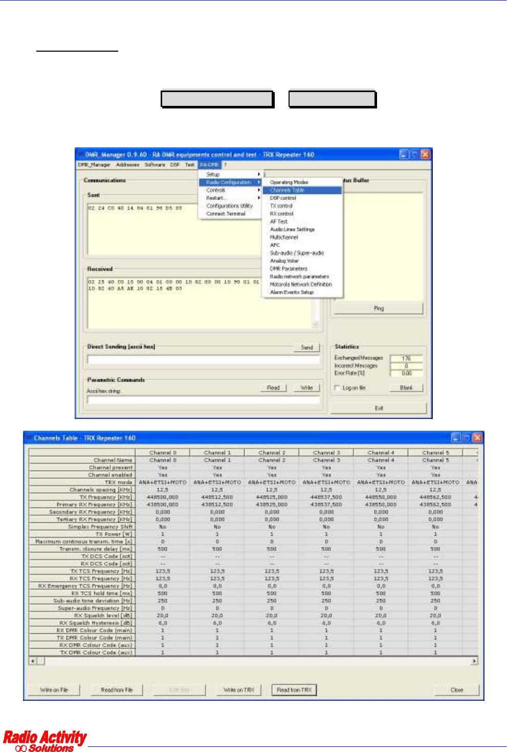
6.2.2.2 CHANNELS TABLE
The channels table displays all the parameters associated with all channels set in the Base Station.
To open the channel table click on, Radio configuration
Channels table , as shown in the figure.

DMR repeater 24/01/2011 Versione 1.1
Documento Riservato - non divulgabile senza autorizzazione
Pag. 33 / 55
The parameters of the channels table are reported in the following table.
Channel name
Channel present Presence of the channel
Channel enabled Enabling of the channel
TRX Mode Indicates all of the possible transmission mode allowed: Analog,
compatible with ETSI standard, compatible with Motorola terminals
Channel spacing [KHz] Allows to choose the channel spacing: 25KHz, 20KHz, 12.5KHz, 10KHz
TX Frequency [KHz] Transmission frequency
Primary RX frequency [KHz] Receiving frequency of the primary receiver
Secondary RX frequency [KHz] Receiving frequency of the secondary receiver
Tertiary RX frequency [KHz] Receiving frequency of the tertiary receiver
Simplex frequency shift If set, when the TX is active, the RX frequency is shifted to avoid
interferences. This is meaningful only for simplex operating mode.
TX power [W] Transmission power
Maximum continuous transmission
[s]
Maximum time allowed for continuous transmission (if 0, this option is
not active)
Transmission closure delay [ms] Time before carrier off after the end of the communication
TX DCS code [oct] Allows to choose a DCS code to transmit (Octal notation)
RX DCS code [oct] Allows to choose a DCS code to receive (Octal notation)
TX TCS frequency [Hz] Allows to set a subaudio tone to transmit
RX TCS frequency [Hz] Allows to set a subaudio tone to receive
RX emergency TCS frequency [Hz] Allows to set an emergency subaudio tone to receive
RX TCS hold time [ms] Time before TCS off after the end of the communication
Subaudio tone deviation Subaudio deviation
Superaudio frequency [Hz] Superaudio frequency
RX squelch level [dB] Allows to set a squelch opening level
RX squelch Hysteresis [db] Difference between squelch opening and closure levels
DMR colour code RX Main RX colour code
DMR colour code TX Main TX colour code
DMR colour code RX aux RX emergency colour code
DMR colour code TX aux TX emergency colour code
To modify the channel parameters click on the column of the channel to modify…

DMR repeater 24/01/2011 Versione 1.1
Documento Riservato - non divulgabile senza autorizzazione
Pag. 34 / 55
…and then click on Edit data :the following form will appear:
It is also possible double click on the column of the channel to modify.
To add a new channel you must select an empty channel in the channels table and modify it as described
above.
The maximum number of channels is 200.
DMR repeater 24/01/2011 Versione 1.1
Documento Riservato - non divulgabile senza autorizzazione
Pag. 35 / 55
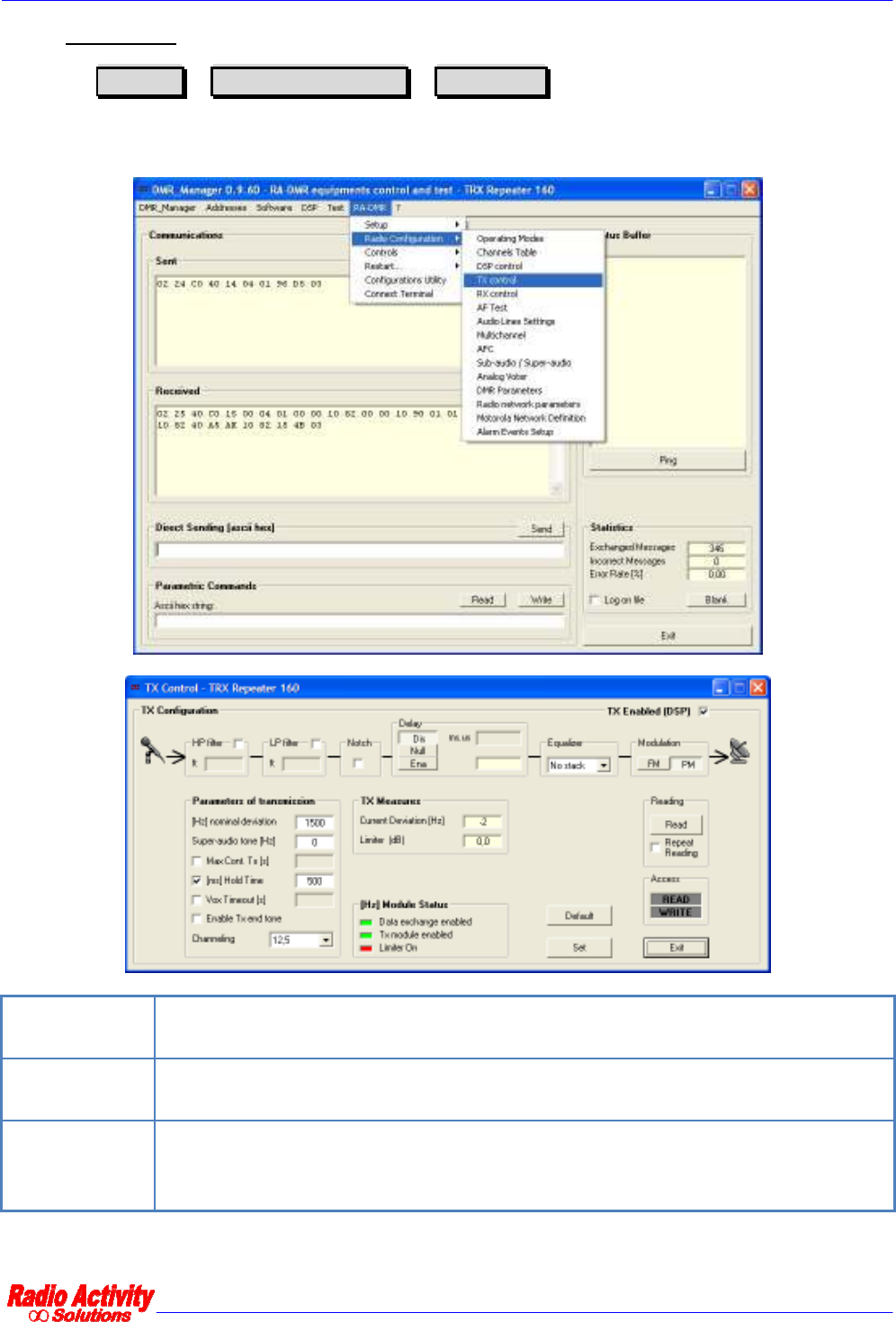
6.2.2.3 TX CONTROL.
Clicking on RA-DMR
Radio configuration
TX control you can adjust the settings of the
transmitter: You can set some filters (low pass, high pass and notch), set a delay, choose to equalize the signal
to transmit (choosing the number of equalizer filter taps) and choose the modulation type (PM or FM).
HP filter It is a programmable high pass filter that can be inserted at the transmitter. It is used to
eliminate the received sub-audio.
LP filter It is a programmable low pass filter that can be inserted at the transmitter. It is rarely used
to limit the bandwidth of the receiver output.
Notch
The notch filter, if enabled, is automatically set on the frequency of sub-audio tone
transmission. It may be useful for reducing the phase distortion in simulcast networks with
a sub-master (it is factory set for a given application).

DMR repeater 24/01/2011 Versione 1.1
Documento Riservato - non divulgabile senza autorizzazione
Pag. 36 / 55
Equalization
Allows to insert a filter that equalizes the phase and amplitude response of the transmitter
in the whole bandwidth (except for the sub-audio tone frequency). It is used in simulcast
networks and it is set in the factory if necessary.
Delay
allows to set a delay on the transmitted signal up to 127 ms
This functionality is organized as follow:
Off: the filter is not active.
On: the filter is active, with minimum delay 1.938ms.
Set: the delay is selectable in the range 0 to 127ms (minimum+1.938ms), step 4 µs.
The settings specified in Parameters of transmission will not be effective (they come from the settings
in the channels table).
To enable these functions click on Set ; All the parameters will assume their original values if you restart the
device, unless you perform a Save in eep operation (see the DMR LAYER CONFIGURATION paragraph).
6.2.2.4 RX CONTROL
Clicking on RA-DMR
Radio configuration
RX control you can adjust the setting of the receiver:
it is possible to choose how to demodulate the received signal, set the squelch opening, enable some filters
(low pass and high pass) and set a time delay.
To enable these functions click on Set ; All the parameters will assume their original values if you restart the
device, unless you perform a Save in eep operation (see the DMR LAYER CONFIGURATION paragraph).

DMR repeater 24/01/2011 Versione 1.1
Documento Riservato - non divulgabile senza autorizzazione
Pag. 37 / 55
HP filter It is a programmable high pass filter that can be inserted at the output of the receiver. It is
used to eliminate the received subaudio.
LP filter It is a programmable low pass filter that can be inserted at the output of the receiver. It is
rarely used to narrow the bandwidth of the receiver.
Delay
Allows you to set a delay on the received signal.
Its function is organized as follow:
Off: the filter is not active.
On: the filter is active, with minimum delay 1.938ms.
Set: the delay is selectable in the range 0 a 127ms (+1.938ms minimum delay), step 4 µs.
6.2.2.5 TEST AF
This form allows to personalize the internal audio generator and can be used to test mobile terminals.
A monitor of the received selective call is available setting the desired standard in the section
Decoded sel call/DTMF
The generator features and analyzer measures are referred to the selected test input, usually TX and RX; if the
lines test form is active, signalling is sent to the selected line.
To enable these functions click on Set ; All the parameters will assume their original values if you restart the
device, unless you perform a Save in eep operation (see the DMR LAYER CONFIGURATION paragraph).

DMR repeater 24/01/2011 Versione 1.1
Documento Riservato - non divulgabile senza autorizzazione
Pag. 38 / 55
6.2.2.6 AUDIO LINES CONFIGURATION (FOR ANALOG USE OR FOR SYNCHRONIZATION AIM ONLY)
Clicking on RA-DMR
Radio configuration
Audio lines setting you can set the input and
output audio lines levels.
DMR users are interested only in using the section Line 1 .
It is possible to set nominal levels for input and output lines, high and low pass filters and delays. The input
signal in fact, after the analog to digital conversion, is regulated in amplitude according to the user’s settings.
The echo canceller is a filter that sums the output signal, after an appropriate phase correction, with the input
signal, in order to minimize signal reflection effects.
This function is selectable by checking Echo canceller
There are also band pass and notch filters to remove PTT and sync tones. The filters are automatically inserted
if you select a tone in the setup line section. You can define the level and the frequency of the used tones and
the filters are automatically aligned with the desired frequency. The extracted signals are sent to the decoding
tones block.
The Line delay block allows to delay the input signal up to 127 ms using a 2 us step. The processing chain
towards the balanced output is the reversal of the processing chain for an input signal.
The In Line and Out Line sections allow to specify the PTT, squelch, synchronism criterions setting the
level and the frequency of the signal.
DMR repeater 24/01/2011 Versione 1.1
Documento Riservato - non divulgabile senza autorizzazione
Pag. 39 / 55
To activate these functions click on Imposta Linea .
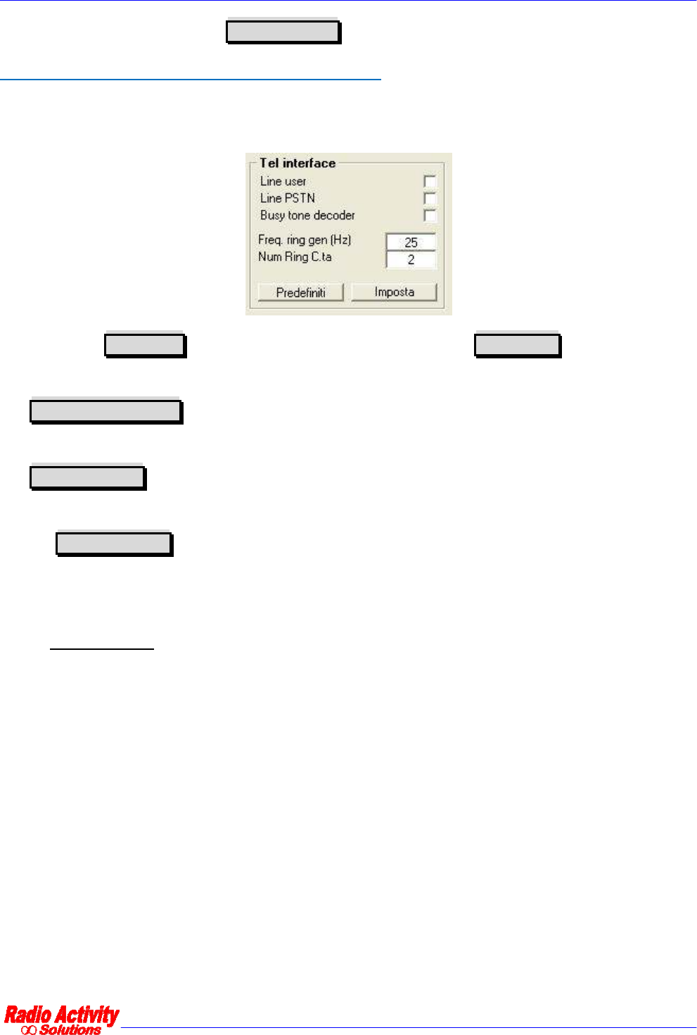
TELEPHONE INTERFACE SETTINGS (FOR ANALOG USE ONLY)
The telephone interface settings are usually set by the technical staff for the specific application. The section
to set these features is the following.
You must check Line user if there is a user side telephone interface, or Line PSTN if there is a
subscriber side telephone interface (BCA-C).
The Busy Tone Decoder function activates the engaged line recognition algorithm (used in the automatic
radio-telephone interface).
The Freq Ring Gen box allows to set the frequency of the telephone call signal (usually 25Hz), which is
active only in user side interfaces (bca-u).
The box Num Ring C.ta allows to set the number of rings after that the telephone interface automatically
engages the line. It is active only for subscriber side telephone interfaces (bca-c).
6.2.2.7 MULTICHANNEL
All DSP modules have a connection bus “MTCH” that allows different radio systems to synchronously exchange
data in particular network configuration. This feature allows to realize many different solutions.
The MTCH bus can hold both anlog audio signals in 16 bit digital format and synchronism/signalling/control
parameters.

DMR repeater 24/01/2011 Versione 1.1
Documento Riservato - non divulgabile senza autorizzazione
Pag. 40 / 55
It is possible to connect up to 12 transceivers directly ,to perform a digital audio matrix in case of complex
base station solutions.
The MTCH protocol is configured on 28 timeslots, selectable to transmit or receive. All the timeslots are
accessible to all the DSP connected to the same bus.
To set the MTCH parameters click on RA-DMR
Radio configuration
Multichannel .
The following form will appear:

DMR repeater 24/01/2011 Versione 1.1
Documento Riservato - non divulgabile senza autorizzazione
Pag. 41 / 55
The section Enable timeslot tx allows the user to select the timeslot to transmit, and the section
Setting RX Timeslot allows to select the timeslot to read from the LAN.
The button Master in the section Features MTCH must be selected in the master radio, so a radio
works as a master and the other radios of the system as slaves.
It is also possible to get the synchronism for the base station by “Multichannel” (see AFC - AUTOMATIC
FREQUENCY CONTROL), as shown in the figure below:
The Signallings section of the multichannel configuration form, displays the timeslot in use (first column)
and related signalling (usually PTT).
To enable these functions click on Set ; All the parameters will assume their original values if you restart the
device, unless you perform a Save in eep operation (see the DMR LAYER CONFIGURATION paragraph).
Note: The configuration of MTCH is set by the factory for the intended use. The use of this form is restricted to
skilled users and only to test the presence of the timeslots in the section Signallings .
6.2.2.8 AFC - AUTOMATIC FREQUENCY CONTROL
Clicking on RA-DMR
RadioConfiguration
AFC it is possible to continuously monitor the
synchronization of the equipment and change some related parameters.
The timing of the Base Station can be extracted from different sources:

DMR repeater 24/01/2011 Versione 1.1
Documento Riservato - non divulgabile senza autorizzazione
Pag. 42 / 55
Menu item Description
Synchronism source Allows to choose the synchronism source
No sync No Synchronism source selected
Digital Synchronism based on a proprietary pattern sent at the beginning of the
transmission and then on superaudio tones.
Internal
The synchronism source is a crystal oscillator placed inside the DSP module, which
has a stability better than 0.5 ppm in the thermal range of functioning. On demand,
higher stability oscillators can be used. The frequency tuning is digitally controlled
and the setting can be stored. An internal self calibration function allows to correct
the natural aging of the oscillator, by simply connecting the receiver to a calibrated
external source.
From multichannel
The synchronism is obtained from Audio LAN connection clock (patch cord on the
rear of the rack). This synchronism can be required for systems with more digitally
linked together radio stations.
Equipment synchronization time <2 s
Long period relative stability 0 ppm
Short period relative stability <0,001 ppm
From PPS GPS
The GPS receiver (inside the station) provides a pulse every second, which is used by
the DSP to clear its frequency and time reference. The time reference allows
automatic equalization of absolute delays of the links (useful in networks with IP
links or MUX SDH links with automatic reconfiguration of routes in case of backbone
failure). In the case of GPS failure the synchronism is automatically switched to
super-audio tone received from the master station (see following method).
Equipment synchronization time <120 s
Long period relative stability 0 ppm
Short period relative stability <0,01 ppm

DMR repeater 24/01/2011 Versione 1.1
Documento Riservato - non divulgabile senza autorizzazione
Pag. 43 / 55
From superaudio
A super-audio tone, superimposed to the analog signal, is the reference for the DSP
to lock its internal clock. That tone, whose frequency can be
freely set between 3100
and 3400 Hz (typ = 3400Hz), is sent 10dB lower than the nominal audio level.
Equipment synchronization time <60 ms
Long period relative stability 0 ppm
Short period relative stability <0,01 ppm
From 4 FSK timeslot Synchronism based on the 4FSK timeslot
To enable these functions click on Set ; All the parameters will assume their original values if you restart the
device, unless you perform a Save in eep operation (see the DMR LAYER CONFIGURATION paragraph).
6.2.2.9 SUBTONE / SUPERTONE
Clicking on RA-DMR
RadioConfiguration
Subaudio/superaudio the subaudio/superaudio
form will appear:
This form allows the user to control and modify the subaudio and superaudio parameters.
You can set the frequency of the TCS tone (both TX and RX) or choose a DPL code (in the octal range 001-777),
which is expressed in octal notation.

DMR repeater 24/01/2011 Versione 1.1
Documento Riservato - non divulgabile senza autorizzazione
Pag. 44 / 55
To enable these functions click on Set ; All the parameters will assume their original values if you restart the
device, unless you perform a Save in eep operation (see the DMR LAYER CONFIGURATION paragraph).
6.2.2.10 ANALOG VOTER
Clicking on RA-DMR
RadioConfiguration
Analogical voter the following form will appear:
This form allows the user to set the analogical voter inputs (in the section Voter parameters ),
In the Voter parameters section you can:
∞ choose the signal sources for the analogical voting and the related setting time,
∞ set the hold time for the voted source (that is the minimum time before source changing),
∞ set the switch time (that is the minimum time between source changing after hold time expiration),
∞ set the signal hysteresis (that is the signal threshold for a valid candidate source).
You can set these parameters specifying the numbers in the section on the right: Initial setting
time [ms] is the searching time for the best signal initially, Hold time [ms] is the time the voted source
is maintained. Switch time [ms] is the time step after which a different input can be voted as the “best”,
Hysteresys [dB] is a threshold: if another signal is Hysteresys [dB] better than the currently voted
one, that signal become the new voted one.
To enable these functions click on Set ; All the parameters will assume their original values if you restart the
device, unless you perform a Save in eep operation (see the DMR LAYER CONFIGURATION paragraph).

DMR repeater 24/01/2011 Versione 1.1
Documento Riservato - non divulgabile senza autorizzazione
Pag. 45 / 55
6.2.2.11 DMR LAYER CONFIGURATION
The Parameters section allows to enable different features:
∞ 4FSK modem: enables the 4FSK modem performed by the DSP,
∞ Receiving as terminal: if checked, the Base Station receives as it were a terminal, without the repeater
features,
∞ Transmission as Base Station: if not checked, the Base Station transmits as it were a terminal, without
the repeater features,
∞ Enabling DMR repeater: enables the repeater features.
Hang time is the time that elapses after the killing of communication to the state of hibernation of the
base station. During this time if the terminal accesses the network it does not need to perform the de-
hibernation procedure and acquisition of synchronization, but can simply access the network. After this time a
terminal, to access the network, must “wake up” the base station by the hibernation state and acquire the
synchronization.
Hold time is the time the TX remains on air after the PTT release.
Displays the colour
codes set in the
channels table
Displays the quality of
the signal received on
the timeslots
It indicates
activity on the
radio channels
These parameters are
set by the technical
staff according to the
network configuration

DMR repeater 24/01/2011 Versione 1.1
Documento Riservato - non divulgabile senza autorizzazione
Pag. 46 / 55
The Signalling section displays radio activities on the two timeslots and also some measures about the
quality of the radio channel.
6.2.2.12 DMR OPERATING MODES
This form allows the user to enable the radio network in simulcast or multisite mode.
In the section Base Station parameters you must specify the role of the Base Station (Master or
Satellite), the voting delay (it is the time that elapses from the current timeslot to the time of arrival of the
packets to be voted). All the other features in this form are set by the technical staff according to the
particular network configuration.
In the section Master , you must insert the IP address of the Master Base Station.
Click Read or Write to read/save the current settings.
Click Write on file Read from file to save or read a configuration on/from a file on the PC.

DMR repeater 24/01/2011 Versione 1.1
Documento Riservato - non divulgabile senza autorizzazione
Pag. 47 / 55
6.2.2.13 DMR SERVICES DEFINITION
You can set this parameters as to be congruent with the DMR Motorola MotoTRBO™ terminals network
settings.
Click Read or Write to read/save the current settings.
Click Write on file Read from file to save or read a configuration on/from a file on the PC.
DMR repeater 24/01/2011 Versione 1.1
Documento Riservato - non divulgabile senza autorizzazione
Pag. 48 / 55
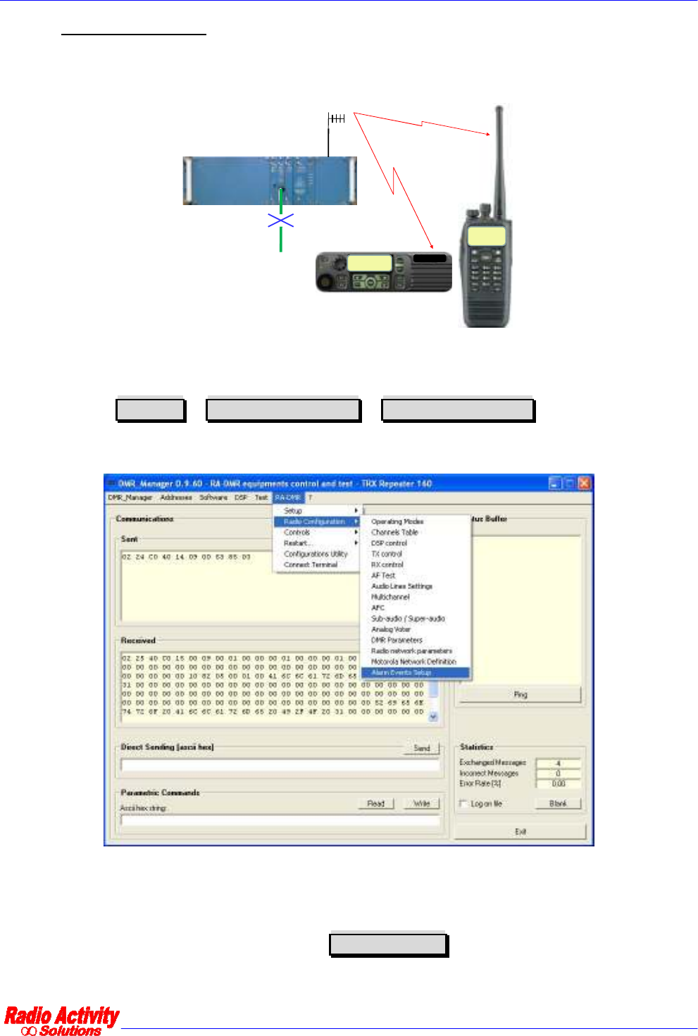
6.2.2.14 ALARM EVENTS SETUP
This new feature is particularly useful because allows the user to receive on his mobile terminal (or on a group
of user terminals) short text messages at the occurrence of certain events.
TCP/IP fail
from BS03
TCP/IP fail
from BS03
RA-XXX
Maintenance group Mototrbo
TM
hand-held/mobile
TCP/IP fail
from BS03
TCP/IP fail
from BS03
Unconfirmed
message
Ethernet
connection failure
Thanks to a new and easy to use DMR_Manager form the user can activate this service with the features that
best suit his needs.
You must click on RA-DMR
Radio configuration
Alarm events setup .
This form allows the user to bind each of the events reported in the table below with a short text message:
when the event occurs the user will receive the text message on the designed mobile terminal and a warning
message when the problem is resolved.
To enable the sending of a warning message, select Alarm enabled

DMR repeater 24/01/2011 Versione 1.1
Documento Riservato - non divulgabile senza autorizzazione
Pag. 49 / 55
It is necessary to insert the ID (or the group ID) of the terminals designed to receive the warning messages.
If the message has to be sent to a group of terminals, select Group ID
It is possible to set how many times sending the alarm message consecutively by selecting Repetitions ,
and how frequently (seconds) by selecting Interval
It is possible to set the timeslot the warning messages will be sent by selecting TS 1 or TS 2 .
Select Write to activate the current settings.
Alarm Event
I/O 1 Active I/O 1 contact
I/O 2 Active I/O 2 contact
Supply undervoltage Voltage supply under the minimum value
Supply overvoltage Voltage supply over the maximum value
Ethernet link Link Ethernet disrupted
MST/SAT sync Loss of synchronism between Master and Satellite
Environmental
temperature Environmental temperature out of range
TX Temperature TX temperature out of range
RX lock RX unlocked
Connection to master Connection with working Master (Satellite only)
Satellite registration Registration of new Satellite (Master only)
Satellite deregistration Deregistration of new Satellite(Master only)
Satellite lost Unreachable satellite(Master only)
GSM/GPRS not working
GSM/GPRS connection not working (only for Base Stations equipped with I/O board
and GSM/GPRS module)
Noise on the RF
channel Not yet active

DMR repeater 24/01/2011 Versione 1.1
Documento Riservato - non divulgabile senza autorizzazione
Pag. 50 / 55
Emergency call on TS1 An emergency call is ongoing on TS1
Emergency call on TS2 An emergency call is ongoing on TS2
DSP generic failure Internal alarm on DSP module
TX generic failure Internal alarm on TX module
RX generic failure Internal alarm on RX module
TRX alarm TRX alarm 1 (strong alarm) is enabled
6.2.3 CONTROLS.
Menu item Description
Controls Displays the current state of the Base Station
I/O status Displays the state of I/O
Radio control Displays and sets the radio operating parameters
Calibration results Displays calibration results (TX,RX and loop)
Audio lines control Displays and sets audio lines parameters
Radio network monitor
Displays the activity of the radio network (form under
development). The data displayed are meaningful only for
connection to a master TRX.
Voting monitor Displays the digital voting (only if the Base Station is configured as
master).
DMR repeater 24/01/2011 Versione 1.1
Documento Riservato - non divulgabile senza autorizzazione
Pag. 51 / 55
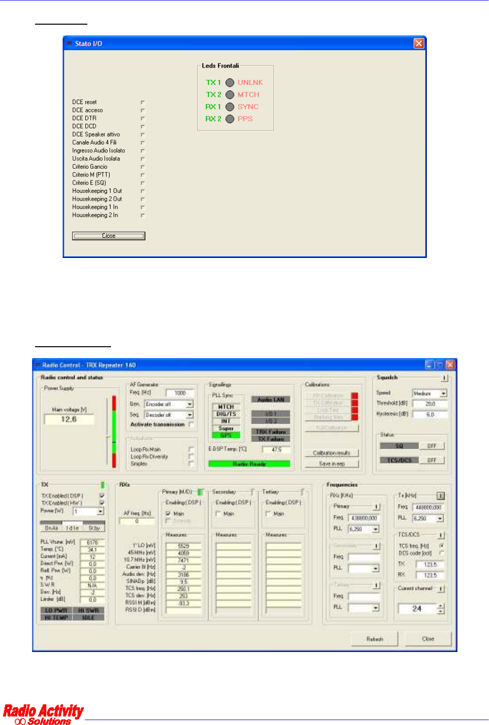
6.2.3.1 I/O STATUS
This form allows to constantly monitor the state of the I/O contacts of the radio and of the LEDs in front of the
DSP module.
6.2.3.2 RADIO CONTROL
This form allows to constantly monitor the state of the radio. It is possible to monitor the power supply, the
synchronism, the internal temperature, the calibration results and many other working parameters.

DMR repeater 24/01/2011 Versione 1.1
Documento Riservato - non divulgabile senza autorizzazione
Pag. 52 / 55
This section displays the TX current settings and all the RX measures.
Power supply
Synchronism
mode
Internal
temperature
Calibration
results

DMR repeater 24/01/2011 Versione 1.1
Documento Riservato - non divulgabile senza autorizzazione
Pag. 53 / 55
The Frequencies section displays the current operating channel, the transmitting and receiving
frequencies and the subaudio settings (TCS,DPL,TCS frequency, DPL code).
6.2.3.3 CALIBRATIONS RESULTS
This form displays the calibration results (TX,RX and loop test).
Clicking Save in eep calibration levels will be saved on eeprom and used in case of unsuccessful result of a
further calibration process.
The Refresh button update the calibration results: it is useful when calibrating, to real time monitor the
calibrations results.
User are strongly advised not to use Write

DMR repeater 24/01/2011 Versione 1.1
Documento Riservato - non divulgabile senza autorizzazione
Pag. 54 / 55
6.2.3.4 AUDIO LINES CONTROL
This form allows the user to perform some tests on the line interfaces. In the section Linea attiva you can
select the line to be tested (clicking on Regola ), in the section Line n you can monitor the lines criteria.
You can also set a audio signal generator connected to the output line and analyze the audio signal coming
from the input line.
6.2.4 RESTART

DMR repeater 24/01/2011 Versione 1.1
Documento Riservato - non divulgabile senza autorizzazione
Pag. 55 / 55
Menu item Description
Restart
DMR Layer Restart the DMR application, which is based on radio layer
TRX Layer Restart the radio Layer which manages the RF section
DSP Restart the DSP
VCTCXO Restart the internal clock
Main Restart the whole software
Reboot Restart the equipment (it is the same of switch off and switch on
the radio)
6.2.5 CONFIGURATIONS UTILITY
This form allows to save to the PC and load from PC the TRX and/or DSP parameters.
6.2.6 CONNECT TERMINAL
The user can activate this feature only by request of the technical staff.