Radio Activity srl RA-160 DMR REPEATER – VHF BASE STATION User Manual use manual
Radio Activity srl DMR REPEATER – VHF BASE STATION use manual
Contents
- 1. use manual
- 2. user manual
use manual
DMR
DIGITAL MOBILE RADIO ASSOCIATION
Radio Activity S.r.l.
Sede: Via Ponte Nuovo, 8 - 20128 Milano – email: radio.activity@fastwebnet.it - www.radioactivity-tlc.com
Tel. 02.36514205 - FAX/Voicebox 1782242408 - Registrazione CCIAA Milano N° 1728248 - P.I./C.F. 04135130963
D
DM
MR
R
R
Re
ep
pe
ea
at
te
er
r
u
us
se
er
r
m
ma
an
nu
ua
al
l
V
Ve
er
rs
si
io
on
n
1
1v
v2
2

DMR repeater 24/01/2011 Versione 1.3
Documento Riservato - non divulgabile senza autorizzazione
Pag. 2 / 31
Index
1 RADIO ACTIVITY DMR REPEATER AND EXPANDIBILITY TO SIMULCAST NETWORK......................4
2 PARAMETERS CONFIGURATION AND REMOTE CONTROL ..........................................................5
3 HARDWARE COMPOSITION OF A BASE STATION .......................................................................6
3.1
PSU: POWER SUPPLY UNIT MODULE.............................................................................................. 6
3.2
DSP: DIGITAL SIGNAL PROCESSOR ................................................................................................. 7
3.3
RECEIVER ...................................................................................................................................... 8
3.4
TRANSMITTER............................................................................................................................... 9
3.5
I/O AND SERVICES MODULE ........................................................................................................ 10
4 TECHNICAL DATA....................................................................................................................11
4.1
REGULATIONS COMPLIANCE........................................................................................................ 11
4.2
GENERAL CHARACTERISTICS ........................................................................................................ 11
4.3
IP interfacing .............................................................................................................................. 12
4.3.1
LAN protocol ................................................................................................................................... 12
4.3.2
LAN requirements ........................................................................................................................... 12
4.3.3
Ports and connectors ...................................................................................................................... 13
4.3.4
Codec VoIP ...................................................................................................................................... 13
4.4
Radio frequency.......................................................................................................................... 14
4.4.1
Transmitter...................................................................................................................................... 14
4.4.2
Receiver........................................................................................................................................... 15
4.4.3
Frequency bands ............................................................................................................................. 17
4.4.4
Commutation band (without duplexer).......................................................................................... 17
4.4.5
Branching requirements ................................................................................................................. 17
4.4.5.1
TX to antenna duplex isolation requirements @10W TX RF power ........................................ 17
4.4.5.2
Suggested RX max input limits on unwanted signals............................................................... 18
4.5
Other specifications .................................................................................................................... 18
4.5.1
Environmental parameters ............................................................................................................. 19
4.5.2
Power supply................................................................................................................................... 19
4.5.3
Mechanical characteristics.............................................................................................................. 19
4.5.4
Audio balanced interfaces............................................................................................................... 19
5 EQUIPMENT INSTALLATION AND MAINTENANCE ....................................................................20
5.1
CONNECTIONS AND PINOUTS...................................................................................................... 20
5.2
EQUIPMENT START UP, RUNNING AND ALARMS: INDICATOR LAMPS ........................................... 27
5.2.1
PSU .................................................................................................................................................. 27
5.2.2
DSP .................................................................................................................................................. 27

DMR repeater 24/01/2011 Versione 1.3
Documento Riservato - non divulgabile senza autorizzazione
Pag. 3 / 31
5.2.3
RX .................................................................................................................................................... 28
5.2.4
TX..................................................................................................................................................... 28
5.2.5
I/O ................................................................................................................................................... 28
5.3
GENERAL RECOMMENDATIONS AND NOTES ................................................................................ 29
5.3.1
Improper use................................................................................................................................... 29
5.3.2
Thermal dissipation......................................................................................................................... 29
5.3.3
Power supply system ...................................................................................................................... 29
5.3.4
Antenna........................................................................................................................................... 30
5.3.5
AF interface ..................................................................................................................................... 30
5.3.6
Manual settings............................................................................................................................... 30
5.3.7
Self-calibration process................................................................................................................... 31
5.3.8
PPS signal ........................................................................................................................................ 31

DMR repeater 24/01/2011 Versione 1.3
Documento Riservato - non divulgabile senza autorizzazione
Pag. 4 / 31
1 RADIO ACTIVITY DMR REPEATER AND EXPANDIBILITY TO SIMULCAST NETWORK
Radio Activity DMR repeater is designed to be modular from both HW and SW point of view, to maximize its
flexibility and minimize costs, physical dimensions, consumptions.
Basic model already has all the characteristics to work as a double standard repeater with all the features of
analogical and digital service. It can be equipped with double receiver to counteract fading effects through
diversity space reception. It is set to host communication and synchronization embedded devices to make the
network expandable to a multi-frequency or iso-frequency multi-site system, with different type of links,
operating with different transportation system topology, like microwave, UHF, fiber optics, generic TCP/IP
connections.
Privileged communication interface is ethernet standard type, maximally compatible with more diffused
technology. This interface supports not only voice and data digital traffic, but also remote control
management, which for Radio Activity equipment is very powerful: it is possible to have a complete monitor
system of equipment status, it is possible to modify each parameter, to down-load each SW and configuration,
launch self-test and calibration functions, to perform specific tests through internal embedded function
generators and software analyzers of the station. For analogical voice traffic instead, a 2/4 wire and criteria
line interface is available.
Remote control service can be performed through an ethernet connection pre-existing in the site, or through
GPRS modem which can be integrated into the station, or through the radio channel and another Radio
Activity station.
Fully modular structure allows to best configure the radio equipment, by adding and/or changing the required
HW and SW functional blocks, to work as simple repeater, multi-frequency multi-site repeater, iso-frequency
multi-site repeater. The basic structure of a base station is made of:
∞ PSU module (not isolated 12Vdc from battery);
∞ DSP module;
∞ RX module;
∞ TX module.
Optional modules and accessories are:
∞ I/O module with line interface with or without GSM/GPRS and GPS unit;
∞ PSU module for isolated power supply sources at 12V, 24V or 48V dc;
∞ RX module with diversity receiver;
∞ Duplexer, circulator or both;

DMR repeater 24/01/2011 Versione 1.3
Documento Riservato - non divulgabile senza autorizzazione
Pag. 5 / 31
∞ Multi-receiver block for star-shaped network architectures with RF links;
∞ Antenna active splitter board.
If a network architecture is needed, Radio Activity base stations can be connected through both a RF or
ethernet link.
2 PARAMETERS CONFIGURATION AND REMOTE CONTROL
Working parameter of the station are completely programmable through a SW package and a PC connection.
The visible (and programmable) parameters set is very wide and extends from radio channel setting to tuning
voltage measure of each local oscillator. The software is called DMR_Manager for single base-stations or
DMR_NetControl for network systems.
Remote diagnostic of radio stations from PC can be performed through the Ethernet interface of the station.
This interface is absolutely standard and very diffused, so relatively simple to be remoted. Radio Activity
stations can be equipped with an embedded GPRS modem which will provide remote access to the station, if
the installation site is covered by this service. Each operation can be remotely performed, exactly the same as
in local connection, including FW down-loading, configuration Down-loading and up-loading, station check,
parameters changing.
Communication and supervision unit can spontaneously transmit diagnostic messages if defined “self-
alarming” events happen. This is useful to automatically check the stations.
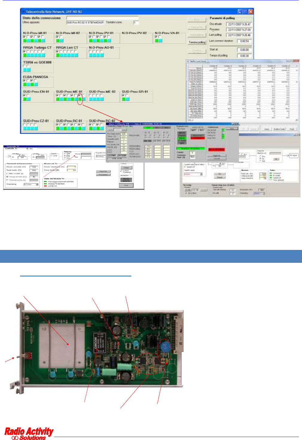
Here following an example of remote control forms:
DMR repeater 24/01/2011 Versione 1.3
Documento Riservato - non divulgabile senza autorizzazione
Pag. 6 / 31
For further details about remote control software, refer to proper documentation (SW user manuals).
3 HARDWARE COMPOSITION OF A BASE STATION
3
3.
.1
1
P
PS
SU
U:
:
P
PO
OW
WE
ER
R
S
SU
UP
PP
PL
LY
Y
U
UN
NI
IT
T
M
MO
OD
DU
UL
LE
E
Equipment is power supplied by nominal
13,8Vdc from battery with negative
shorted to ground and with a maximum
current absorption of 5 A. In case of
other power supply sources, other PSU
models are available, DC/DC (nominal
12-24-48V, isolated) or AC/DC (nominal
220V) with battery charger.
Input polarity and
over-current
protection
External I/O
polarity
Isolated external
I/O power supply
DC/DC 6.5Vcc
Space for optional
floating ground power
supply
Input lightening
protection
DMR repeater 24/01/2011 Versione 1.3
Documento Riservato - non divulgabile senza autorizzazione
Pag. 7 / 31
3
3.
.2
2
D
DS
SP
P:
:
D
DI
IG
GI
IT
TA
AL
L
S
SI
IG
GN
NA
AL
L
P
PR
RO
OC
CE
ES
SS
SO
OR
R
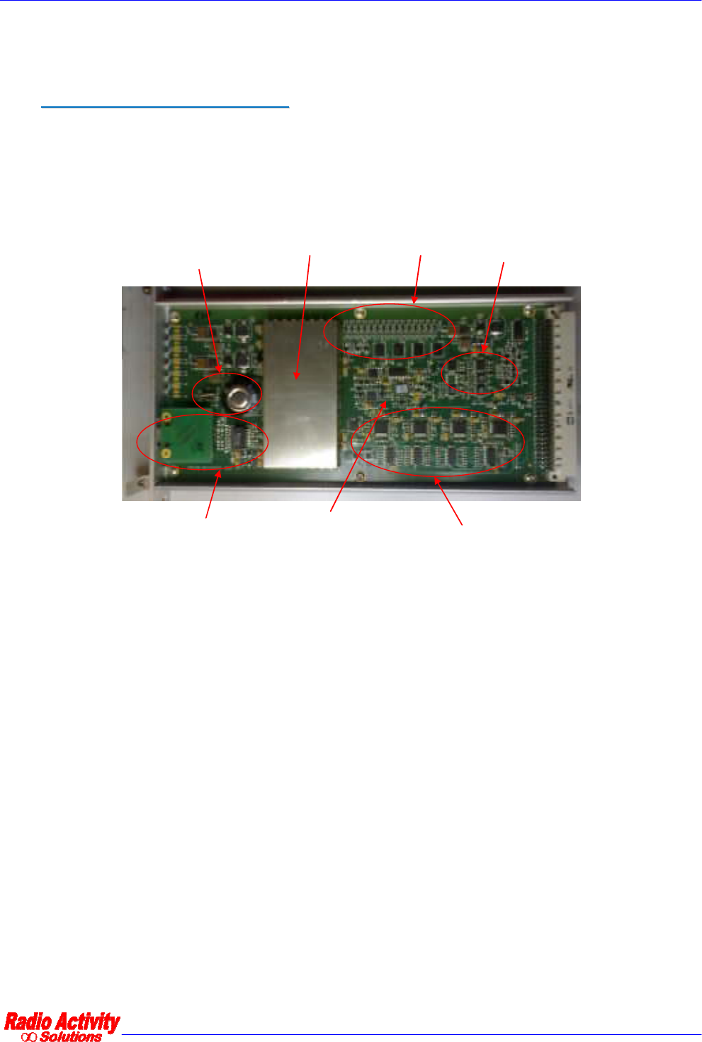
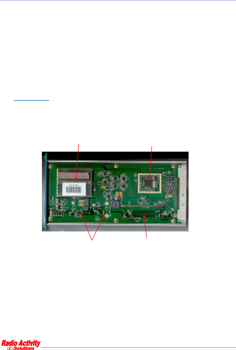
The core of system’s “physical layer” is this unit which via software performs every function of signal
processing inside radio station. What other equipments implement by adding boards (like synchronizers,
phase and amplitude equalizers, signal decoders, modem, etc.), here are implemented by routines which can
be freely matched, down-loaded and with superior performance.
DSP and Processor cores
VCTCXO
reference D/A and A/D converters
and audio filters
Ethernet LAN
RTC
I/O
AUDIO LAN
This board can process up to 8 analogical duplex signals ensuring 70 dB of SNR; it can manage 16 logical signals
which can be configured both as input and output.
Communication and control functions of module are entrusted to a microprocessor which manages
communications with external world and with other equipment modules. The microprocessor is based on
LINUX operative system; it can manage a LAN ethernet 10/100 interface both for copper line and for fiber
optic links, it is equipped with 4 serial ports to manage radio modules, GPS, auxiliary devices, external hosts; it
is equipped with a Real Time Clock with tampon battery; it controls an embedded PLL to synchronize the
entire station upon an internal (VCTCXO 0.5 ppm) or external temporal reference. DSP module is equipped
with a synchronous serial port according RS485 standard levels, which can be programmed up to 16Mbit/s and
can be used to interconnect together more transceiver or additional equipments.
Main performed functions are the following:
DMR repeater 24/01/2011 Versione 1.3
Documento Riservato - non divulgabile senza autorizzazione
Pag. 8 / 31
∞ Frequency self-tuning device
∞ Deviation self-calibration device
∞ Analogical and digital demodulation
∞ RF circuits testing
∞ Phase modulator calibration
∞ RF output power control
∞ Low frequency lines management
∞ DMR protocols management
∞ Digital signals processing
∞ Management, conditioning and routing of traffic and remote control signals from and towards
external world
3
3.
.3
3
R
RE
EC
CE
EI
IV
VE
ER
R
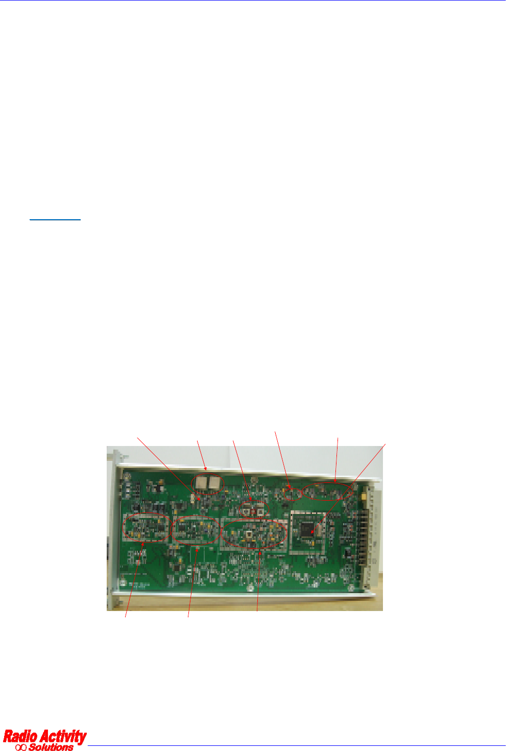
Receiver can be supplied as single or double for space diversity reception. Main and diversity channels are
completely independent and coherent (sharing the same local oscillators) and they are designed according to a
triple conversion heterodyne structure, with 45 MHz and 10.7 MHz intermediate frequencies and with
vectorial conversion to base-band.
Channel standard bandwidth is 12.5 KHz, but the receiver is prepared to accept also a settable channel
bandwith of 25 KHz (with double funnel option) for special applications.
Vectorial receiver gives to the DSP input the electromagnetic field vector, as received from antennas, without
performing any demodulation. By this way the DSP can sum with the appropriate phases the received signals
to obtain a “soft diversity” reception. This corresponds to an electronic antennas alignment in order to receive
the maximum available information along the incoming signal direction.
III° LO 10.7MHz II° LO 34.3MHz
I° LO Frx+45MHz (VHF)
I° LO Frx-45MHz (UHF)
Input filter and low
noise amp.
High IP3 MixerXTAL filter
45MHz
XTAL filter
10.7MHz Micro-
controller
IF system
A further input (TX Test input), common for both receivers (main and diversity) is available, for the receiver
self-test and for modulator calibration. Through a DSP command, the receiver can switch its input onto test
signal generated inside transmission synthesizer module. That signal, amplitude calibrated by Factory, is
modulated at receiving frequency and received by DSP. A fundamental test loop is close by this way.
DMR repeater 24/01/2011 Versione 1.3
Documento Riservato - non divulgabile senza autorizzazione
Pag. 9 / 31
The switching between normal and test input is implemented through PIN diodes.
Receiver modules is managed by a microcontroller unit whose program is hosted inside internal e2prom flash
memory to lower parasitic emissions. This FW can be loaded through serial connection. The microcontroller, in
addition to managing internal function of the unit, transfers measured parameters to the control unit through
115.2 Kb/s serial line.
The board is realized with surface mounting components (SMD) to maximally reduce dimensions.
Modular unit is housed in a shielded, 4TE high box for 220mm Eurocards. On the frontal panel 2 LEDs are
placed for monitoring internal PLLs lock status.
3
3.
.4
4
T
TR
RA
AN
NS
SM
MI
IT
TT
TE
ER
R
Transmitter module is realized with surface mounting components (SMD) and it is housed in a shielded, 8TE
box for 220mm Eurocards, with an heatsink mounted on side, with a thermal resistance of about 1.2°K/W. The
unit can be extracted from the front side of the rack.
MOS power amplifiers
power detecting strip lines
microcontroller
synthesizer
On the frontal panel two LEDs are placed to monitor the transmitter status.
Base-band functions, equalizing, limiting, low-pass filtering end eventual emphasis functions are performed by
the DSP unit, which provides also for nominal and maximum deviation calibration by looping modulator with
receiver.
Modulator is digital vectorial, then the synthesized signal by local oscillator implements the frequency shifting
of the signal which has been directly modulated in base-band by DSP unit and transferred to transmitter
through its I and Q components.

DMR repeater 24/01/2011 Versione 1.3
Documento Riservato - non divulgabile senza autorizzazione
Pag. 10 / 31
The amplifier is realized by three cascaded stages and RF output power regulation (between 1 and 25W) is
implemented by controlling the gates voltages of MOSFET amplifier stages. Power amplifier works in C class
and ensures a very high efficiency, lowering the needed power from supply system and lowering the thermal
dissipation inside the cabinet. Direct and reflected output power are measured by a directional coupler.
Power control circuit acts in a closed loop and keeps constant the total power at MOSFET drain. Inside the
module a thermal sensor is hosted and it is directly connected to the internal microcontroller which enables
the command for air forced cooling fan of the cabinet if the temperature rises over 85°C. Anyway, if reflected
power or mosfet temperature exceeds protection threshold, regulation circuit will lower output power up to
safe levels for transmitter.
The current flowing into final amplifier transistor is continuously monitored by microcontroller to verify the
correct functioning and to reveal an eventual efficiency degradation.
The module is equipped with an harmonic filter to lower spurious emissions under required levels by existing
regulations.
3
3.
.5
5
I
I/
/O
O
A
AN
ND
D
S
SE
ER
RV
VI
IC
CE
ES
S
M
MO
OD
DU
UL
LE
E
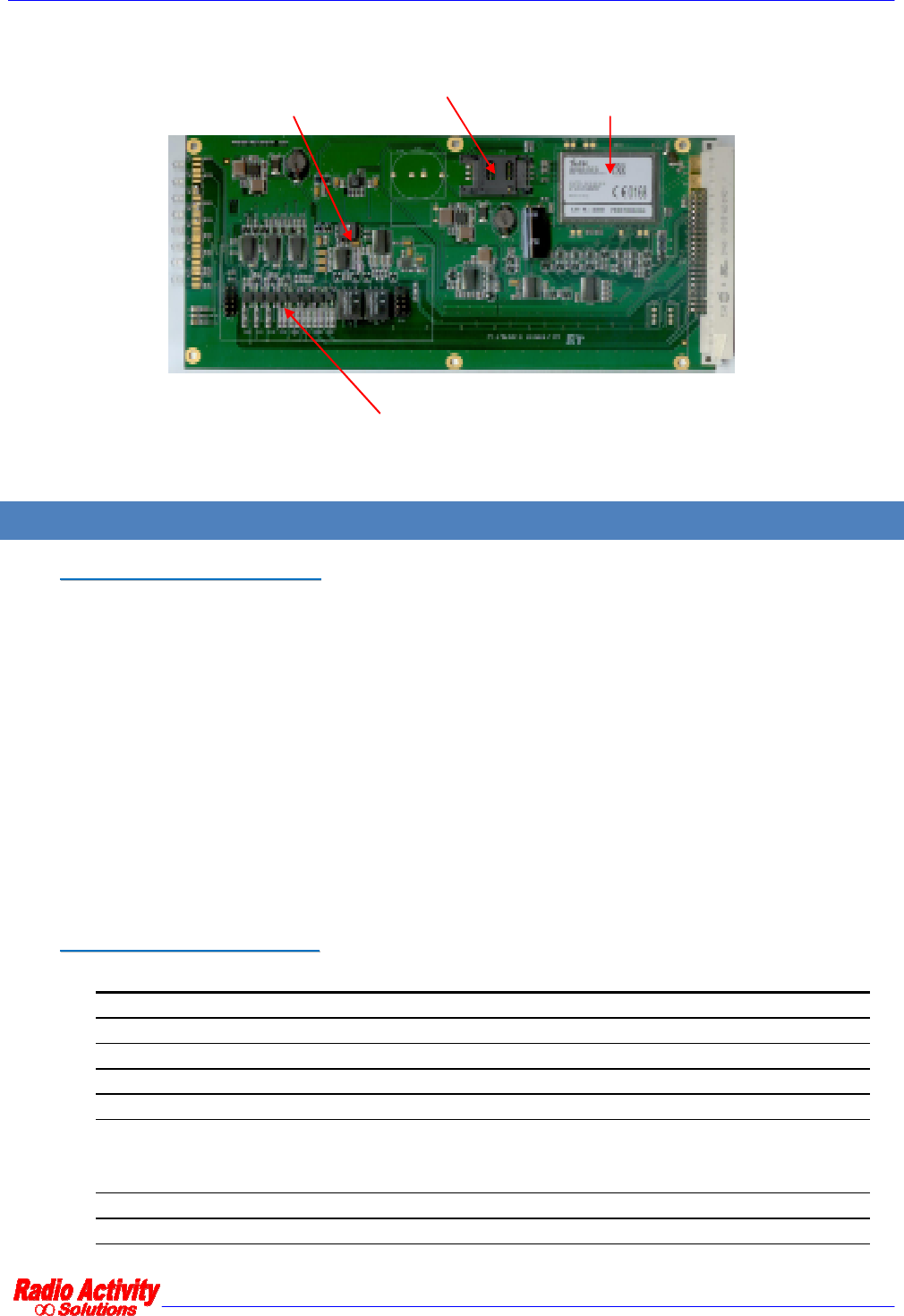
I/O and Services module is a unit integrating different interfaces and functions, that for some applications can
be optional but for others become essential. For this reason the module can be differently equipped with its
different logical blocks, according to the particular application. The embedded block are the following:
∞ Telephone line interface: 2/4W+E&M line interface to remote analogical audio and perform automatic
routing through telephonic line
∞ Opto-isolated I/O: 2 input + 2 output contacts programmable (both N.O. or N.C.) for remote
monitoring local sensors and remote controlling local actuators
∞ Opto-isolated alarms: two alarms output (1 warning + 1 fatal)
∞ Analogical input: 2 not isolated inputs, 1 for voltage sensing (0..20V referred to ground) + 1 for current
sensing (4…20mA). These input can be connected the first in parallel and the latter in series with the
analogous ones of other similar equipments
∞ GSM/GPRS modem: embedded communication module for remote control if the site is covered by
GSM or GPRS service. It requires only an external passive antenna
∞ GPS receiver: embedded receiver for GPS service, with high precision Pulse Per Second (PPS) output
function in order to synchronize the station. Only an external active antenna is required
∞ RS232 converter: 115.2Kbit/s serial interface for remote control
I/O and services module is equipped with 8 LEDs on the frontal panel to monitor the status of opto-isolated
I/O, the status of GPRS modem and the presence of PPS.
Modular unit is housed in a shielded, 4TE high box for 220mm Eurocards.
DMR repeater 24/01/2011 Versione 1.3
Documento Riservato - non divulgabile senza autorizzazione
Pag. 11 / 31
GSM/GPRS - GPS
BF line interface
SIM HOLDER
I/O contacts
4 TECHNICAL DATA
4
4.
.1
1
R
RE
EG
GU
UL
LA
AT
TI
IO
ON
NS
S
C
CO
OM
MP
PL
LI
IA
AN
NC
CE
E
Equipments are compliant with existing regulations, in particular:
1. EN 300 086-2: Technical characteristics and test conditions for radio equipment for analogue
speech.
2. EN 300 113-2: Technical characteristics and test conditions for non speech radio equipment
for the transmission of data.
3. ETSI TS 102361: Electromagnetic compatibility and Radio spectrum Matters (ERM); Digital
Mobile Radio (DMR) Systems.
The equipment is able to manage OSI stack layers 1 – 2 – 3 of DMR protocol, making active interaction
possible with mobile terminals.
4
4.
.2
2
G
GE
EN
NE
ER
RA
AL
L
C
CH
HA
AR
RA
AC
CT
TE
ER
RI
IS
ST
TI
IC
CS
S
Funnel 12.5 KHz (25KHz optional for special purpose)
Maximum channels number 200
Operating mode Dual-standard, analogical and digital
Operating mode selection Totally automatic
Frequency stability +/- 0.5 ppm
I/O
4 opto-isolated OUT (2 alarms + 2 generic)
4 IN (2 digital opto-isolated + 2 analogical referred to
ground)
Voice/data digital interface LAN 10/100 copper or fiber optic
Analogical audio interface 2/4W + E/M (BCA-C/U optional)

DMR repeater 24/01/2011 Versione 1.3
Documento Riservato - non divulgabile senza autorizzazione
Pag. 12 / 31
Base Bandwidth Audio 300-3400 Hz ±1dB
Modulation 0-5 KHz
Calibration and tests Automatic at start-up and/or by remote control
Remote control Via ethernet / serial RS232 / GPRS
4
4.
.3
3
I
IP
P
I
IN
NT
TE
ER
RF
FA
AC
CI
IN
NG
G
4.3.1 LAN PROTOCOL
4.3.2 LAN REQUIREMENTS
Protocols for voice packets
UDP/IP (ipv4), unicast (from RA-TI-XXX to master) and multicast
(from master to RA-TI-XXX), with DSCP set to “EF” (Telephony
service class), according to RFC 4594
Protocols for BS “internal” network
control
UDP/IP (ipv4), unicast and multicast, with DSCP set to “CS6”
(Network Control service class), according to RFC 4594
Protocols for remote control, setup
and surveillance
UDP/IP and TCP/IP (ipv4) unicast and broadcast with DSCP set to
“AF13” (High-Throughput Data
service class), according to RFC
4594
Audio format Analog: 64 kb/s – 8 bit x 8 KHz linear coded
DMR: AMBE II+
TM
(Advanced Multi-Band Excitation)
Audio frame block net payload
Analog: 60 ms – 480 bytes/samples
DMR selectable single/double timeslot: 60 ms –
27 bytes each
timeslot

DMR repeater 24/01/2011 Versione 1.3
Documento Riservato - non divulgabile senza autorizzazione
Pag. 13 / 31
4.3.3 PORTS AND CONNECTORS
UTP LAN Port Ethernet 10BT/100TX (auto MDI/MDI-X) on an RJ45 socket
Optical LAN Port (option) Ethernet 100FX on SC-SC socket
Serial control Port RS232 V.24 asynchronous 600 ÷ 115200 bps on a DB9 female
connector
BUS control Port TTL on a dual-in-line 10 pins male connector
4.3.4 CODEC VOIP
Uncoded audio source 64 kbps – 8bitx8KHz
Net bit-rate (1CH) 2450 bps
FEC Coded bit-rate (1CH) 3600 bps
Audio frame block 20ms
Jitter (deviation of averaged packet
time delay)
The Base Station is able to compensate Jitter delay up to 200 ms.
The total delay averaged + jitter must not exceeds 400ms (each
way)
Maximum delay
The Base Station is able to compensate round trip delay less then
900ms (jitters included)
Packet loss < 0.1 %
SLAVE:
70 kb/s in analog to/from Master
24 kb/s in DMR to/from Master (both timeslots)
Minimum bandwidth (network
signaling and remote control polling
inclusive) MASTER to serve N SLAVES (both timeslots):
70 kb/s in analog to Slaves, 70 kb/s x N from Slaves
24 kb/s in DMR to Slaves, 24 kb/s x N from Slaves

DMR repeater 24/01/2011 Versione 1.3
Documento Riservato - non divulgabile senza autorizzazione
Pag. 14 / 31
Coder algorithm AMBE II+
TM
(Advanced Multi-Band Excitation)
DMR compatibility Motorola Mototrbo series
4
4.
.4
4
R
RA
AD
DI
IO
O
F
FR
RE
EQ
QU
UE
EN
NC
CY
Y
Radio Transceiver model RA080, RA160, RA450, RA900, typical values.
4.4.1 TRANSMITTER
Module output power 1/5/10/15/20/25 W
RF final transistor protection to high
temperature 85°C +/- 5°C progressively reducing the RF power
Available modulation FM, PM, GFSK, 4FSK
Modulation bandwidth 0 .. 5000 Hz
Synthesis step 4/5/6,25/10 KHz
Transmitting duty cycle Continued 100%
ROS protection Min.10’ in short circuit as well as in open circuit
Adjacent channel noise
-75 dBc @25KHz
-65 dBc @12.5KHz
FM distortion < 1.5 %
Noise
-56 dBp @25KHz
-50 dBp @12.5KHz

DMR repeater 24/01/2011 Versione 1.3
Documento Riservato - non divulgabile senza autorizzazione
Pag. 15 / 31
Frequency stability 0.5 p.p.m.
Max reverse input signal
-20dBm to avoid intermodulation
+20dBm no damage
4.4.2 RECEIVER
Maximum sensitivity
-113 dBm @20 dBp SINAD
-118dBm @5% BER without diversity
-121dBm @5% BER with diversity
Operating maximum input -10 dBm
Maximum input without permanent
damages +10 dBm
Reception mode Vectorial I e Q
Received signal band 0..5000 Hz
Synthesis step 6,25 KHz
Co-channel protection
8 dB @25 KHz
12 dB @12.5KHz
Adjacent channel selectivity
73 dB @25 KHz
62 dB @12.5 KHz
Blocking protection 80 dB
Intermodulation protection 75 dB
Intercept 3° order IP3in +15 dBm

DMR repeater 24/01/2011 Versione 1.3
Documento Riservato - non divulgabile senza autorizzazione
Pag. 16 / 31
Distortion <2 %
Noise
-53 dBp @25 KHz
-47 dBp @12.5 KHz
-60 dBp (with voice search option)
Frequency stability 0.5 p.p.m.
DMR repeater 24/01/2011 Versione 1.3
Documento Riservato - non divulgabile senza autorizzazione
Pag. 17 / 31
4.4.3 FREQUENCY BANDS
Model Frequency band
RA-900 UHF – HH => 865-925 MHz
RA-450 UHF – H => 410-440 MHz
RA-450 UHF – L => 430-470 MHz
RA-160 VHF – H => 145-174 MHz
RA-080 VHF – L => 68-88 MHz
4.4.4 COMMUTATION BAND (WITHOUT DUPLEXER)
Band TX RX
UHF – H 30 MHz 14 MHz
UHF – L 30 MHz 12 MHz
VHF – H 28 MHz 28 MHz
VHF – L 20 MHz 20 MHz
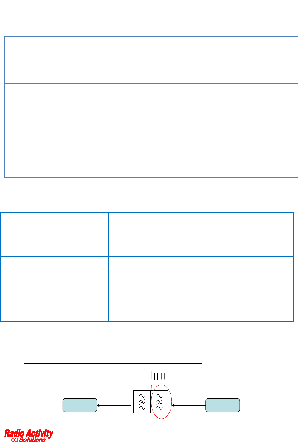
4.4.5 BRANCHING REQUIREMENTS
4.4.5.1 TX to antenna duplex isolation requirements @10W TX RF power
TX
RX main
DMR repeater 24/01/2011 Versione 1.3
Documento Riservato - non divulgabile senza autorizzazione
Pag. 18 / 31
Band +/-40MHz +/-9MHz +/-4.5MHz +/-3MHz +/-1.5MHz +/-0.8MHz
UHF – HH 75dB
UHF – H/L 75dB 75dB
VHF – H 75dB 75dB 75dB 78dB 81dB 85dB
VHF – L 75dB 75dB 75dB 75dB 78dB 81dB
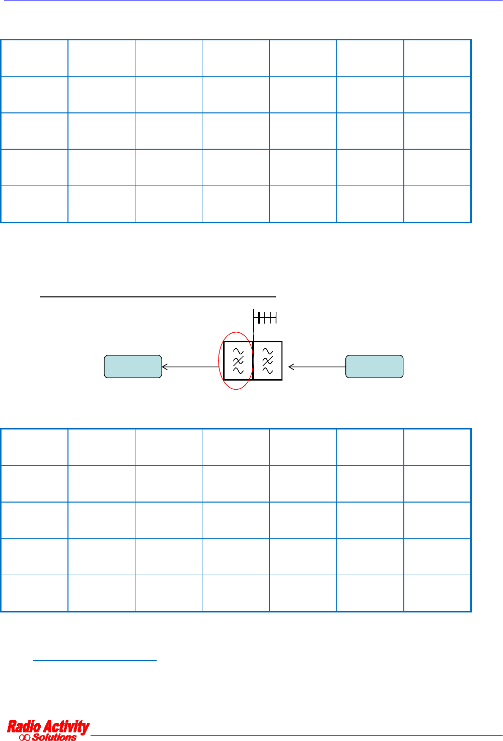
4.4.5.2 Suggested RX max input limits on unwanted signals
TX
RX main
Band +/-1MHz +/-500KHz +/-100KHz +/-50KHz +/-25KHz +/-12.5KHz
UHF – HH -32dBm -43dBm -45dBm -47dBm -49dBm -58dBm
UHF – H/L -32dBm -41dBm -43dBm -44dBm -48dBm -56dBm
VHF – H -32dBm -40dBm -42dBm -43dBm -47dBm -54dBm
VHF – L -32dBm -36dBm -38dBm -40dBm -43dBm -50dBm
4
4.
.5
5
O
OT
TH
HE
ER
R
S
SP
PE
EC
CI
IF
FI
IC
CA
AT
TI
IO
ON
NS
S

DMR repeater 24/01/2011 Versione 1.3
Documento Riservato - non divulgabile senza autorizzazione
Pag. 19 / 31
4.5.1 ENVIRONMENTAL PARAMETERS
Operating Temperature -25 ÷ +55 °C
Storage Temperature -40 ÷ +70 °C
Relative Humidity Max 80% not condensed
4.5.2 POWER SUPPLY
Nominal Voltage
11 - 15 Vcc (neg. ground)
19 – 36 Vcc (floating ground)
38 – 60 Vcc (floating ground)
Max ripple 30 mVpp
Polarity reversal protection -70 V
Short-circuit protection Electronic protection with automatic restore and double fuse on
input line
Power consumption TX: 55 W @20W RF
RX: 8 W
4.5.3 MECHANICAL CHARACTERISTICS
Dimensions 128 x 426 x 280 mm
1/2 rack 19” x 3TU x 280 mm mounting
Weight 6.0 Kg
4.5.4 AUDIO BALANCED INTERFACES
Interface type 2/4 wires isolated balanced line on RJ45 socket
Line isolation 1500 V
Used audio bandwidth 300÷3400 Hz
Input/output Impedance 600 Ohm

DMR repeater 24/01/2011 Versione 1.3
Documento Riservato - non divulgabile senza autorizzazione
Pag. 20 / 31
Side tone reflection < - 20 dB
Output nominal level -20 .. 0 dBm
Input nominal level -20 .. 0 dBm
Hang line current 10..50 mA
Level adjust software by 0.1dB step
Ring detect 60..120 Vpp @25Hz
Ring generator (option) 90Vpp @25Hz
Release tone detection 3 pulses of 425Hz @50% duty 250ms/250ms
5
EQUIPMENT INSTALLATION AND MAINTENANCE
5
5.
.1
1
C
CO
ON
NN
NE
EC
CT
TI
IO
ON
NS
S
A
AN
ND
D
P
PI
IN
NO
OU
UT
TS
S
RA-XXX base-stations require a reduced set of connections for normal working conditions (power supply, with
optional “power good” and “inhibit” controls, antennas, eventual ethernet link for remote control or for multi-
site link). The transceiver is equipped with other sockets in order to connect it to auxiliary equipment, like
other transceivers, multi-receivers, audio interfaces, remote site control devices, fan cooler, and so on.
On the front side of the equipment there are only the 10BT/100TX ethernet connector for the remote control
of the equipment and for data/audio packets communication, the power on/off switch and the LEDs for
monitoring the status of the equipment. All other connectors are placed on the back side of the transceiver.
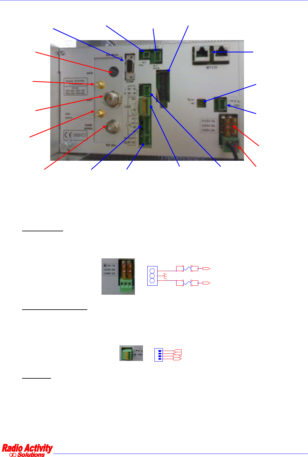
The following picture shows the fundamental connections in red color and the optional ones in blue color.
DMR repeater 24/01/2011 Versione 1.3
Documento Riservato - non divulgabile senza autorizzazione
Pag. 21 / 31
GPS
antenna
GSM /
GPRS
antenna
Main RX /
TX antenna
Diversity RX
antenna
12Vcc
Power
supply
Inhibit /
Power_good
contacts
Alarm
outputs
I/O
contacts
Audio line
interface
Analog
inputs
6V-12V output,
max 200mA
FAN
activation
RS232
port
Main RX
antenna
MTCH
synchronous
serial interface
fuses
External
synchronism
input
Matrix
connector
The following connections are available (for each one, a picture of the connector and the related schematic
diagram of back plane PCB are shown):
∞ Power Supply: 13.2Vdc with negative to ground, or optionally 24Vdc or 48Vdc isolated. The equipment
is protected from polarity inversion. Two automotive type 10A fuses work against accidental short
circuits. The connector has 3 poles (+Vin, rack ground, -Vin) with 5.08mm pitch
11
22
33
P12
3 - 5.08pitch
F2
FUS-AUTO-10A
F1
FUS-AUTO-10A
-Vin
+Vin
∞ Power supply control: normally closed optically isolated “PG” (Power Good) contact ensures the
presence of internal correct supplies; “INH” (Inhibit) contact should be kept closed/open to switch
off/on the equipment. Input contact is internally polarized with +/-12V.
1
3
2
4
P6
MCV 0,5/ 4-G-2,5
PG_A
COM_OPTO
PG_B
/INHIBIT
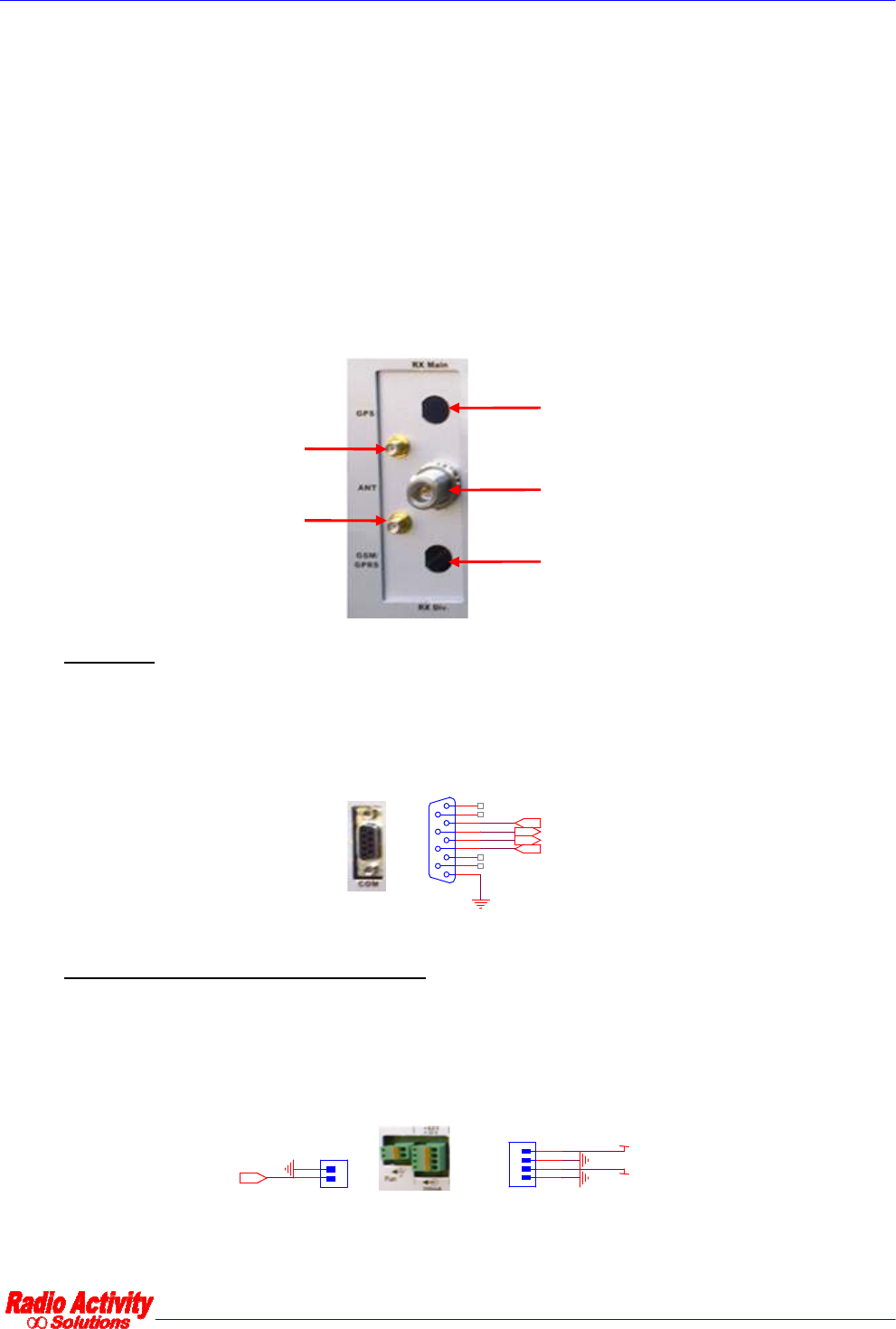
∞ Antennas: up to 5 antenna connectors can be mounted according to the specifications of equipment.
1. A female N-type connector is connected to the output of the duplexer (if present) or to
the output of the TX (if branching is not mounted inside the equipment);
2. A female BNC-type connector (above the N-type one) is present if duplexer is not
mounted inside the equipment. It is connected to main RX;
DMR repeater 24/01/2011 Versione 1.3
Documento Riservato - non divulgabile senza autorizzazione
Pag. 22 / 31
3. A female BNC-type connector (below the N-type one) is present if the base station is
equipped with the diversity receiver. This connector is directly connected to the input of
the diversity receiver, without any cavity filter/isolation inside the equipment. Care
should be taken in designing external branching and radiant system;
4. A female SMA-type connector for embedded GPS receiver. The equipment supplies
5Vdc through this connector for the remote active antenna (which is requested with a
minimum gain of 20dB and possibly equipped with a rejecting filter for out-of-band
spectral components);
5. A female SMA-type connector for GSM/GPRS embedded transceiver. A passive antenna
is required. (The SIM holder is mounted inside I/O module.).
GPS
antenna
GSM /
GPRS
antenna
Duplex antenna /
TX antenna
Diversity RX
antenna
Main RX
antenna
∞ COM port: 9 poles D-SUB type socket, connected to an optional RS232 serial port (115.2Kbit/sec,
8,N,1) for remote controlling the equipment by a PC. This is a secondary access port to the base
station, auxiliary/alternative respect to the main ethernet port. The RS232 driver is mounted on the
I/O module.
5
9
4
8
3
7
2
6
1
J4
SJV9
rts_232
CTS
cts_232
TX-PC
RX-PC
TX_232
RX_232
RTS
∞ “Fan” and “Auxiliary power supply output”: the first is an active low, open collector type contact, not
isolated, which can activate an optional external cooling system if RF power amplifier temperature
would rise over 90°C. In normal ambient and working conditions, no cooling system is required. The
second connector supplies 12Vdc 200mA and 6Vdc 200mA (not isolated) for eventual auxiliary devices
.
1
2
P2
MCV 0,5/ 2-G-2,5
HI-TEMP
6V_SERV
12V_SERV
1
3
2
4
P1
MCV 0,5/ 4-G-2,5
DMR repeater 24/01/2011 Versione 1.3
Documento Riservato - non divulgabile senza autorizzazione
Pag. 23 / 31
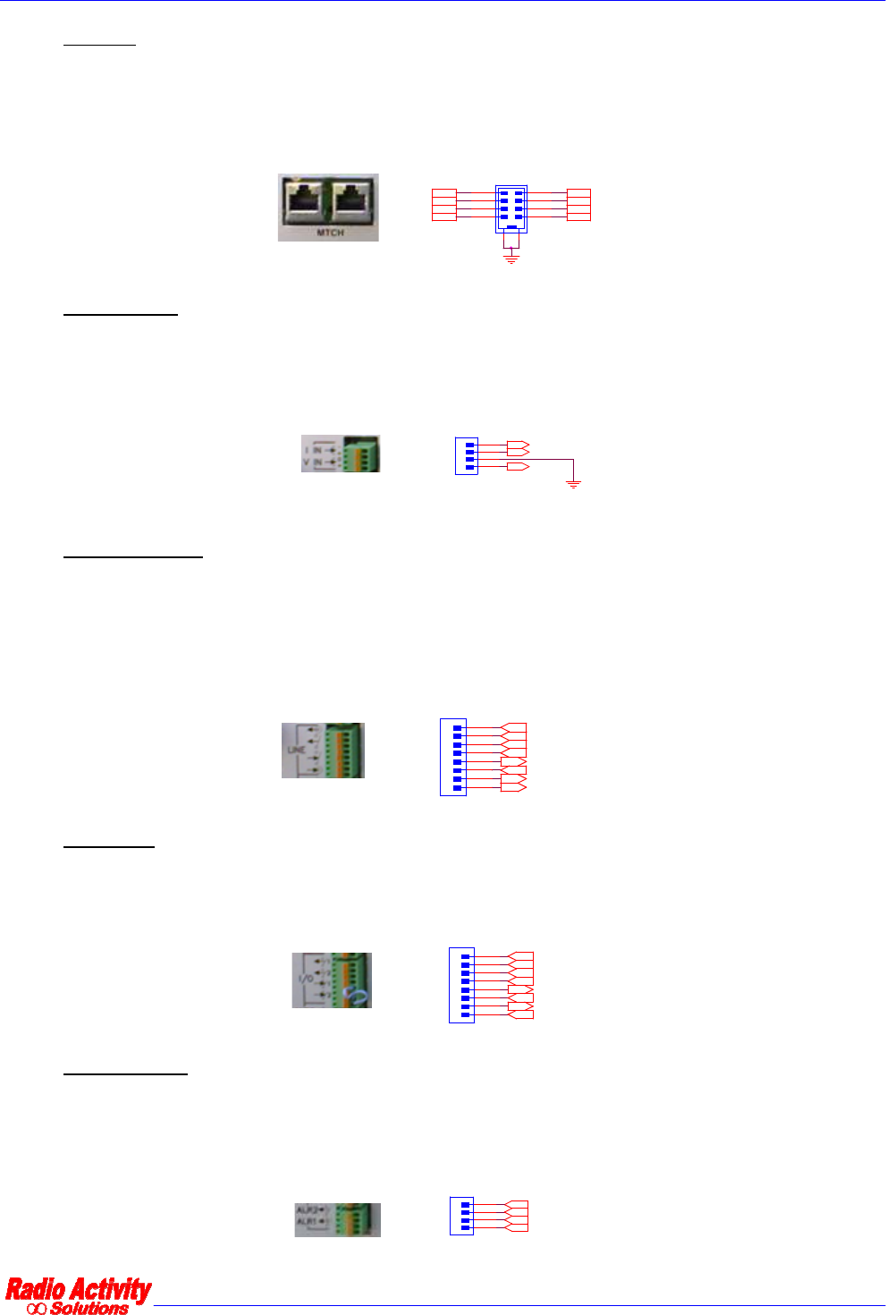
∞ “MTCH”: two 8 poles RJ45 connectors (connected in parallel) give access to internal digital audio
multichannel (synchronous, TDMA, 4Mbit/s speed, serial interface with custom protocol). These
connectors are used to implement any particular system and network architectures which require the
base station to be connected to other devices equipped with the same MTCH interface.
DT0/DR0_B
RFS0_A
SCLK0_A
DR0_A DR0_B
RFS0_B
DT0/DR0_A
SCLK0_B
1
3
5
7
2
4
6
8
11
12
J2
RJ45
∞ Analog inputs: a 4 poles connector with 2 not isolated analog inputs, one for current (dc, from 0 to
20mA) and one for voltage (dc, from 0 to 20V referred to GND). Current inputs of different
equipments ca be connected in series; voltage inputs of different equipment can be connected in
parallel.
AN_I_IN-
1
3
2
4
P5
MCV 0,5/ 4-G-2,5
AN_V_IN
AN_I_IN_+
∞ AF line interface: a 8 poles connector to connect the base station to a telephone or console line (both
2 or 4 wire lines, also with E and M criteria) to monitor analog traffic only or for synchronization aim.
Starting from the top, the pinout is as following: output line (use this contacts in case of 2 wire line –
bidirectional -), squelch input contact (optically isolated, normally open), PTT output contact (optically
isolated, normally open, internally polarized with +/-12V), input line(only for 4 wire line).
COM_SQ_OUT_0
1
3
5
7
2
4
6
8
P9
MCV 0,5/ 8-G-2,5
COM_OPTO
BF0-IN-B
BF0-OUT-B
BF0-IN-A
BF0-OUT-A
SQ_OUT_0
PTT_IN_0
∞ Digital I/O: a 8 poles connector with 4 optically isolated digital contacts, 2 outputs (in the upper part,
normally open) and 2 inputs (in the lower part, normally closed). Input contacts are internally
polarized with +/-12V.
COM_1_OUT
COM_2_OUT
1_OUT
2_OUT
1_IN
2_IN
1
3
5
7
2
4
6
8
P10
MCV 0,5/ 8-G-2,5
COM_OPTO
COM_OPTO
∞ Alarm outputs: a 4 poles connector with 2 optically isolated digital contacts (normally open). Alarm 2
output will be closed if the base station undergoes a temporary out of service or if a slight problem
happens (warning); alarm 1 output will be closed during power on of the station or if a heavy problem
happens (stable out of service).
1
3
2
4
P13
MCV 0,5/ 4-G-2,5
COM_ALR_1_OUT
COM_ALR_2_OUT
ALR_1_OUT
ALR_2_OUT
DMR repeater 24/01/2011 Versione 1.3
Documento Riservato - non divulgabile senza autorizzazione
Pag. 24 / 31
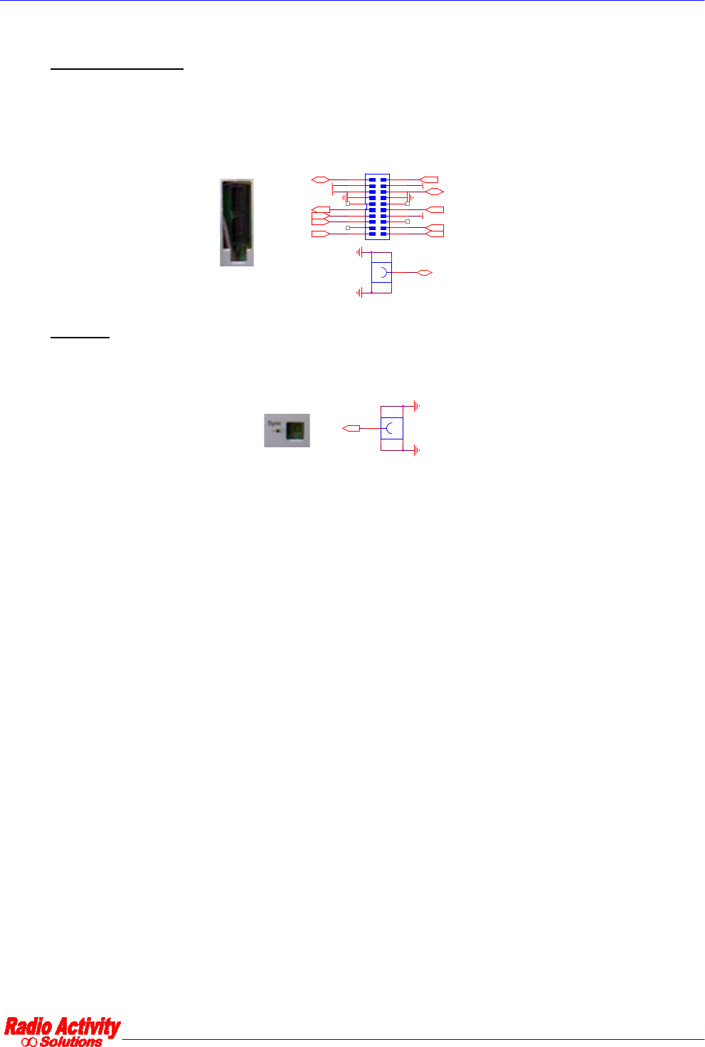
∞ “Matrix” connector: a 20 poles connector (2x10, pitch 2.54mm) and a coaxial MCX-type connector
with a set of signals which can be used to implement any particular system and network architectures
which require the base station to be connected to other devices equipped with the same MTCH
interface.
52
43
1
J9
JCOAXMINI90
*
LO_TEST
12V_SERV
6V_SERV
SYNC_12M8
URES
6V_SERV
RESERVED
RESERVED
ON-LINE
12V_SERV
NOR/RIS
RX/TX
PPS_GPS
LINE_OPTO COM_OPTO
1
3
5
7
9
11
13
15
17
19
2
4
6
8
10
12
14
16
18
20
P4
SP20
COM_MS_RX COM_MS_TX
∞ SYNC IN: a MCX coaxial connector for eventual external synchronization input signal. Normally this
input is unused, it is needed for special applications which require an external synchronization source
(sinusoidal, at 12.8MHz, with level between -10 and 0 dBm).
52
43
1
J6
JCOAXMCX90
SYNC_IN
DMR repeater 24/01/2011 Versione 1.3
Documento Riservato - non divulgabile senza autorizzazione
Pag. 25 / 31
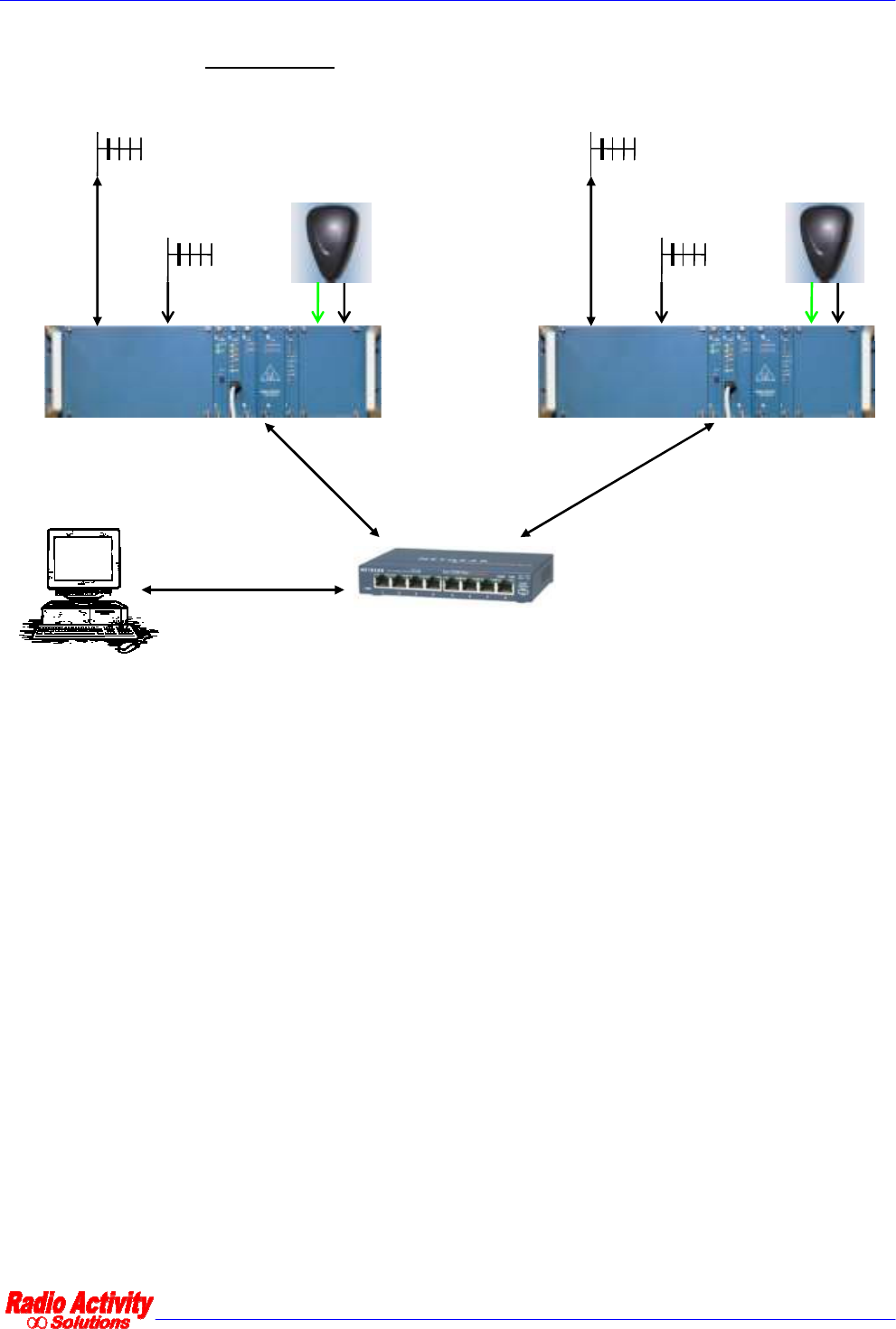
For example, the following picture shows how two repeaters should be connected to implement a
simulcast network with ethernet links.
GPS and
GSM/GPRS
antenna
Ethernet SWITCH
LAN cable
LAN cable
LAN cable
Remote control PC
“DMR Manager”
GPS
GSM/
GPRS
DMR master
Diversity RX
antenna,
if needed
Main RX /
TX antenna GPS and
GSM/GPRS
antenna
GPS
GSM/
GPRS
DMR slave
Diversity RX
antenna,
if needed
Main RX /
TX antenna
In case of UHF links, 2 transceivers are needed for each site, one for local broadcasting and the other
for the link between master and satellite. They can be mounted into the same rack 19” 3U. The
following picture shows the back side of a RF linked satellite.
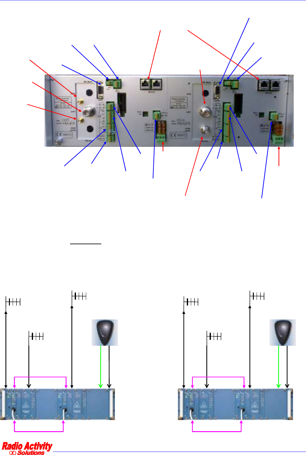
DMR repeater 24/01/2011 Versione 1.3
Documento Riservato - non divulgabile senza autorizzazione
Pag. 26 / 31
GPS
antenna
GSM /
GPRS
antenna
Main RX /
TX antenna
Diversity RX
antenna
12Vcc
Power
supply
Inhibit /
Power_good
contacts
Alarm
outputs
I/O
contacts Audio line
interface
Analog
inputs
6V-12V output,
max 200mA
FAN
activation
RS232
port Main RX /
TX antenna
6V-12V output,
max 200mA
FAN
activation
RS232
port
12Vcc
Power
supply
Alarm
outputs
I/O
contacts
Audio line
interface
Analog
inputs
Inhibit /
Power_good
contacts
MTCH terminations to be connected
together by an ethernet cord
For this example, the following picture shows how two repeaters should be connected to implement a
simulcast network with UHF links. Two ethernet patch cord are needed to connect together the
MTCH ports and the ethernet ports of the two radios; they are represented in pink color.
l
GPS and
GSM/GPRS
antenna
LAN cable
GPSGSM/
GPRS
DMR master
Diversity RX
antenna
(broadcast),
if needed
Main RX /
TX antenna
(link)
Main RX /
TX antenna
(broadcast)
MTCH cable
GPS and
GSM/GPRS
antenna
LAN cable
GPSGSM/
GPRS
DMR slave
Diversity RX
antenna
(broadcast),
if needed
Main RX /
TX antenna
(link)
Main RX /
TX antenna
(broadcast)
MTCH cable

DMR repeater 24/01/2011 Versione 1.3
Documento Riservato - non divulgabile senza autorizzazione
Pag. 27 / 31
5
5.
.2
2
E
EQ
QU
UI
IP
PM
ME
EN
NT
T
S
ST
TA
AR
RT
T
U
UP
P,
,
R
RU
UN
NN
NI
IN
NG
G
A
AN
ND
D
A
AL
LA
AR
RM
MS
S:
:
I
IN
ND
DI
IC
CA
AT
TO
OR
R
L
LA
AM
MP
PS
S
The base stations of RA-xxx series are designed to reduce as much as possible the maintenance work. To this
aim, specific solutions have been implemented to prevent aging drifts.
Each time the base station is switched on, a self-calibration process is performed in order to finely tune the
modulation and the demodulation parameters. This process checks the total loop BF-TX-RX-BF by looping the
synthesizer output of the TX on the input of the RX and the DSP unit can store the results into flash memory
and update the older ones which have been previously saved. The correct results of a calibration process are
symptom of an optimal tune of the radio transceiver. If the calibration process ends with errors, the
transceiver can anyway work correctly by loading the older tuning parameters and the newer ones are not
saved.
On the frontal panel of the RA-xxx base stations, there are some LED lamps for monitoring the status of the
equipment. They have different meanings, during power on process, respect to normal running condition.
Here following, a description of the meaning of the LEDs, grouped module by module. In general, if the
equipment works correctly, all leds are off or green; if a warning arises, one or more leds start flashing in red
color; if a problem or an alarm arises, one or more leds are red. (An exception should be made for eventual
leds which show the status of line output criteria: they are red if the corresponding criteria are enabled).
5.2.1 PSU
When the base station is switched on, the 2 leds of PSU module should be green both:
∞ the upper led is red if the supplied input voltage is too low or too high; it is off in case of inverted
polarity of connection to power supply system; it is green if the supplied input voltage belong to the
correct working range;
∞ the lower led is green if the secondary internal voltages are correctly supplied by PSU module,
otherwise it is off.
5.2.2 DSP
When the base station is switched on, DSP module performs a booting process, during which the upper 4 leds
are orange; the lower 2 leds respectively monitor the activity through ethernet connection (the 5
th
led flashes
with orange color during data communication) and the connection to ethernet network (the 6
th
led is green if
the connection is established), therefore they are independent from the logical status of the module. At the
end of the booting process, the DSP module executes the following steps in sequence, which are also visually
indicated by leds:
∞ FW uploading to clock generator (3
rd
led flashes in orange color);
∞ FW uploading to DSP and reset of peripheral modules (2
nd
led flashes in orange color)
∞ DSP startup (1
st
led flashes in orange color)
∞ RX self-calibration(2
nd
led flashes in red color)
∞ TX self-calibration (1
st
led flashes in red color)
∞ TXRX loop self-calibration (3
rd
led flashes in red color)

DMR repeater 24/01/2011 Versione 1.3
Documento Riservato - non divulgabile senza autorizzazione
Pag. 28 / 31
∞ Frequency setup of working channel (1
st
led flashes in red color in case of fine calibration of
parameters)
At this point the DSP reaches its normal running status and the leds behave as follows:
∞ 1
st
upper led: it flashes in green color if calibration of TX failed; it is green during transmission on TS1;
it flashes in red color if multichannel is enabled but the DSP cannot receive data correctly (this
function will be assigned to the 2
nd
led in future SW version); otherwise it is off;
∞ 2
nd
led: it flashes in green color if calibration of RX failed; it is green during transmission on TS2; it
flashes in red color if multichannel is enabled but the DSP cannot receive clock correctly (this function
will be assigned to the 3
rd
led in future SW version); otherwise it is off;
∞ 3
rd
led: it flashes in green color if calibration of TXRX loop failed; it is green during reception from
TS1; otherwise it is off;
∞ 4
th
led: it flashes in green color if the system clock is locked to the synchronism source; it is green
during reception from TS2; it flashes in red color if the DSP is not locked to the synchronism source as
set in “AFC” routine; otherwise it is off;
∞ 5
th
led: it flashes in orange color during data communication through ethernet port; otherwise it is off;
∞ 6
th
led: it is green if the ethernet connection is established; otherwise it is off.
During analog transmission (or reception), both the leds related to transmission (or reception) on TS1 and TS2
are green, because both the timeslot are busy during analog communication.
5.2.3 RX
RX module is equipped with two leds:
∞ the upper led flashes very fast in green-red color during data reception-transmission through control
serial port of the module (during FW upload process on peripheral microprocessor); it is red in case of
unlock of the upper local oscillator which is used to tune the RX; otherwise it is off;
∞ the lower led flashes in red color if there is no application (main) FW uploaded to peripheral
microprocessor; it flashes in green color during start-up booting process; it is red in case of unlock of
at least one of the IF local oscillators; otherwise it is off.
5.2.4 TX
TX module is equipped with two leds:
∞ the upper led flashes very fast in green-red color during data reception-transmission through control
serial port of the module (during FW upload process on peripheral microprocessor); it is red in case of
unlock of the local oscillator or during transmission if the generated RF power is less than a half of its
set value; it is green during transmission with a greater RF power than 10W; otherwise it is off;
∞ the lower led flashes in red color if there is no application (main) FW uploaded to peripheral
microprocessor; it flashes in green color during start-up booting process; it is red in case of excessive
SWR and consequent forced interruption of transmission; it is green during transmission with a lower
(or equal) RF power than 10W; otherwise it is off.
5.2.5 I/O
I/O module is equipped with eight leds, of which the upper 6 reflect the status of corresponding digital I/O
contacts that are present on the back side of the equipment, while the lower 2 reflect the status of the
embedded GSM/GPRS-GPS device. They behave as follows:

DMR repeater 24/01/2011 Versione 1.3
Documento Riservato - non divulgabile senza autorizzazione
Pag. 29 / 31
∞ the upper led is red if a heavy problem happens to the base station or during its booting process
(meaning a stable out of service status); the corresponding alarm 1 is active; otherwise the led is off;
∞ the 2
nd
led is red if the base station undergoes a temporary out of service (example during a channel
change) or if a slight problem happens (warning); the corresponding alarm 2 is active; otherwise the
led is off;
∞ the 3
rd
led is green if the output contact 1 is active (normally open);
∞ the 4
th
led is green if the output contact 2 is active (normally open);
∞ the 5
th
led is green if the input contact 1 is active (normally closed);
∞ the 6
th
led is green if the input contact 2 is active (normally closed);
∞ the 7
th
led flashes in green color if PPS signal is generated (Attention: after the first reception of a valid
GPS signal for generating PPS signal, this signal is always generated by the module, it is eventually
locked to local clock of the divice in case of temporary unlock with GPS reference. The DSP module
checks its effective validity); otherwise it is off;
∞ the 8
th
led flashes in green color if embedded GSM/GPRS module is enabled; it flashes fast if the SIM
card is missing, slower if the SIM card is present; it is red during transmission of GSM bursts;
otherwise it is off.
5
5.
.3
3
G
GE
EN
NE
ER
RA
AL
L
R
RE
EC
CO
OM
MM
ME
EN
ND
DA
AT
TI
IO
ON
NS
S
A
AN
ND
D
N
NO
OT
TE
ES
S
5.3.1 IMPROPER USE
It is recommended to install the equipments in closed cabinet, to allow only authorized people to access to
them, in order to avoid handling or improper use of equipments and to avoid accidental contact with hot
surfaces.
5.3.2 THERMAL DISSIPATION
Outlet cabinet containing the equipments should be designed to ensure a good internal air flux for heating
dissipation. A free slot of at least 1UT is recommended between two near equipments.
In case RF transmitter is set for its maximum power, it is active with a duty-cycle near to 100% and ambient
temperature could be above 40°C, a larger respect area must be considered around the rack and an air forced
cooling system should be eventually designed (“FAN” contact of the equipment can be used to switch on and
off cooling system). The transmitter is protected against over-temperature: if the RF mosfet temperature
arises over 90°C, the microprocessor will automatically decrease the generated RF power in order to make the
amplifier work in safety conditions. The nominal RF power will be restored as soon as the mosfet temperature
will decrease below 60°C.
5.3.3 POWER SUPPLY SYSTEM
Internal power supply voltage is nominally set to 13.2V dc from battery, with negative pole connected to
ground, and it is protected against polarity inversion, over-voltage, under-voltage, short-circuits. Isolated PSU
modules can be optionally supplied for 12V/24V/48V dc input voltage.

DMR repeater 24/01/2011 Versione 1.3
Documento Riservato - non divulgabile senza autorizzazione
Pag. 30 / 31
The equipment is designed to be powered by a safe supply source which grants a double insulation of output
voltage from dangerous voltages. The electric plant must contain a switch to cut off power supply lines,
according to national law and directives.
It is recommended to use power supply sources with low impedance output stage to make the hot swap
controller of PSU properly work. For example, if power supply has an output filter with an inductive equivalent
impedance, a capacitor can be added in parallel in order to reduce the resulting output impedance.
Power supply cable dimensions must be calculated for a maximum current absorption of 7A @13.2V DC, or 4A
@24V, or 2A @48V, in order to avoid significant voltage drop, especially after fast transient. They should be
protected by a fuse or a short circuit protection system which should be placed as near as possible to power
supply source.
The transceiver is equipped with a couple of automotive type fuses, placed near power supply input
connector, for short circuits protection. This type of fuses is designed for battery up to 55 Ah; for bigger
battery power, other more effective devices should be placed before the transceiver to grant a correct power
cut off.
It is also recommended to connect a good ground reference to the rack and to its metal components, by using
both central pin of power supply connector and the screw on the right side of the rack. A second screw for
ground connection is place on the back side of the rack.
5.3.4 ANTENNA
Antenna discharger are recommended to prevent damages due to eventual atmospheric discharges. These
devices should be placed on antenna connection cable, just before equipments installation shelter, and they
must be connected to an optimum ground reference.
Attention must be paid also to connect the eventual diversity receiver to the radiant system: the input of this
receiver is directly connected to BNC connector on the back side of the rack, without any filter. The
corresponding antenna must be placed far enough from the transmitting antenna in order to avoid receiver
desensitization and to get the correct isolation. To avoid any problem, it is recommended to insert a notch or a
pass-band cavity to protect the receiver.
If an external branching is connected to the equipment, it must be designed to ensure the needed isolations
between transmitter and receivers.
5.3.5 AF INTERFACE
If a 2/4W telephone line is connected to the equipment, external primary discharges are recommended to
prevent damages due to eventual atmospheric discharges on the line. The internal AF interface is protected
only by secondary dischargers.
5.3.6 MANUAL SETTINGS
The equipments of RA-xxx series are designed to minimize the set of needed hardware settings. Before
installing the equipments the following manual settings must be verified if digital I/O and AF interface are used
respectively:

DMR repeater 24/01/2011 Versione 1.3
Documento Riservato - non divulgabile senza autorizzazione
Pag. 31 / 31
∞ voltage polarity, used to supply the optically isolated digital input contacts: inside PSU module, a 4
poles dip-switch allows to set the polarity, according the following table:
1 ON
2 ON
3 OFF
4 OFF
+12V
1 OFF
2 OFF
3 ON
4 ON
-12V
∞ AF line interface characteristics: inside I/O module, a 2 pole dip-switch allows to set the line type (2W
or 4W) and the input impedance of eventual 4W line (600 ohm or high), according the following table:
1 ON Zin (4W) = 600 ohm
1 OFF Zin (4W) = High
2 ON 2W
2 OFF 4W
5.3.7 SELF-CALIBRATION PROCESS
During self-calibration process internal parameters of modulator and demodulators are tuned by generating a
signal through the synthesizer of the transmitter, by automatically connecting its output to the input of the
receiver and by analyzing the received signal. If a strong signal is received by the external antenna during self-
calibration, it is possible that the process ends with errors (a corresponding “warning” alarm will be displayed
on both frontal leds and monitor of PC for remote control). In this case the DSP will load from flash memory
the previously saved parameters without any problem for the transceiver.
To obtain better results from self-calibration process, it is recommended to set the calibration frequency as
near as possible to the transmitter frequency; if there is a range of allowed frequencies for transmission, it is
recommended to set the centre of this range as the calibration frequency.
5.3.8 PPS SIGNAL
For applications in simulcast networks where the source of synchronization is the PPS signal by GPS, if this
signal is missing, the radio coverage of the areas which are reached by several repeaters with the same field
strength, is not ensured. Attention must be paid in choosing and placing the GPS antenna.