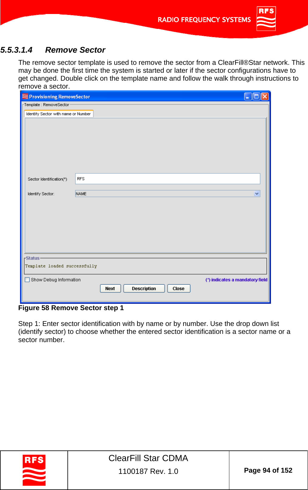
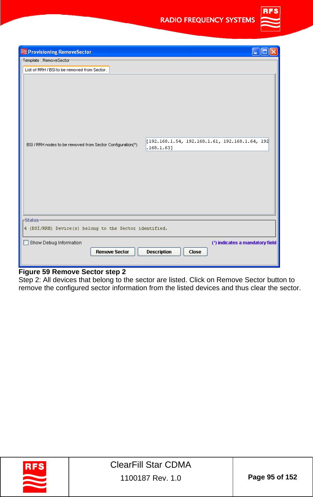
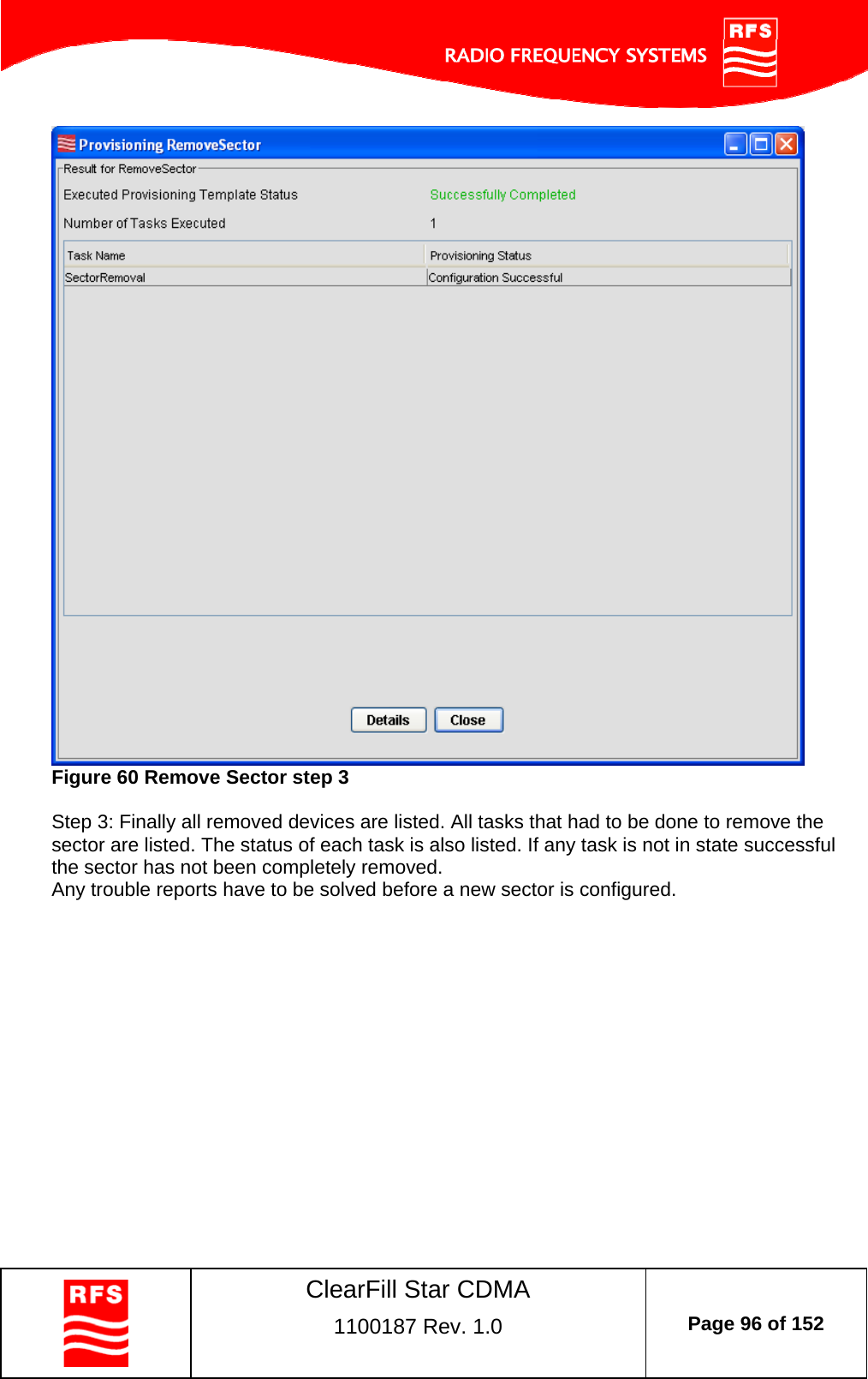
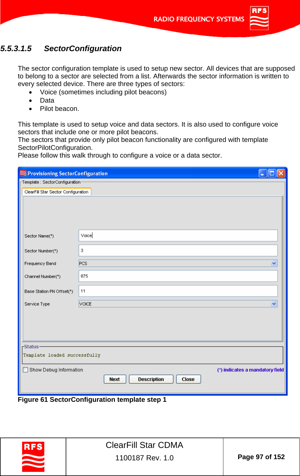
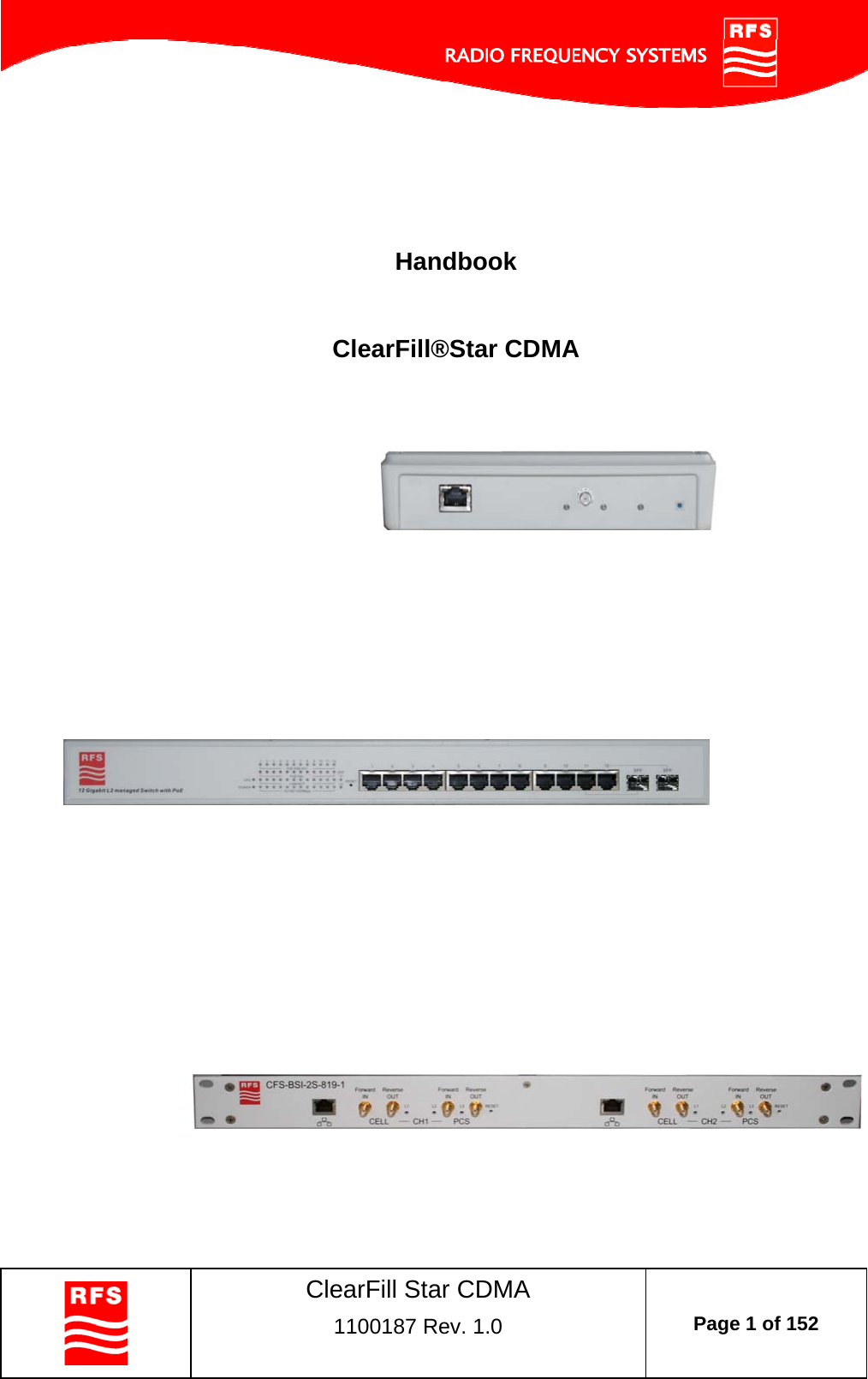
Radio Frequency Systems W1000220 Remote Radio Head User Manual Handbook
Radio Frequency Systems Inc Remote Radio Head Handbook
UserManual.wiki
>
Radio Frequency Systems
>
W1000220 User Manual
Handbook
Navigation menu
Upload a User Manual
Namespaces
Wiki Guide
HTML
PDF
Info
Views
User Manual
Discussion / Help
Navigation


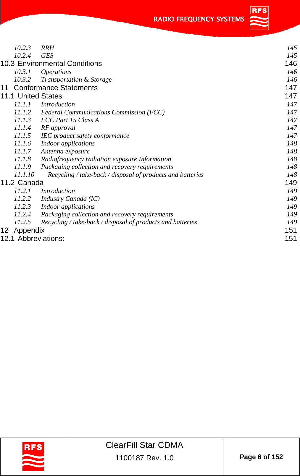


![ClearFill Star CDMA 1100187 Rev. 1.0 Page 25 of 152 The following typical wall attenuations were observed: Type Attenuation [dB] Thin concrete wall - 10cm (4 inches) 5 Thick concrete wall - 13cm (5 inches) 13 External wall front with windows 8 External wall front without windows 10 Porous concrete 4 Dry wall, sheetrock 1-2 Wood structure, wood door 1 Glass 2 Concrete floor 13 Brick Wall - 10cm (4 inches) 4 Brick Wall - 6cm (2 inches) 3 Partitions metal 1-2 Plastic structure 0.5 Glass with metal grid 8 Table 2 Typical attenuation for different materials (source: Wireless Valley)](https://usermanual.wiki/Radio-Frequency-Systems/W1000220/User-Guide-1205570-Page-25.png)
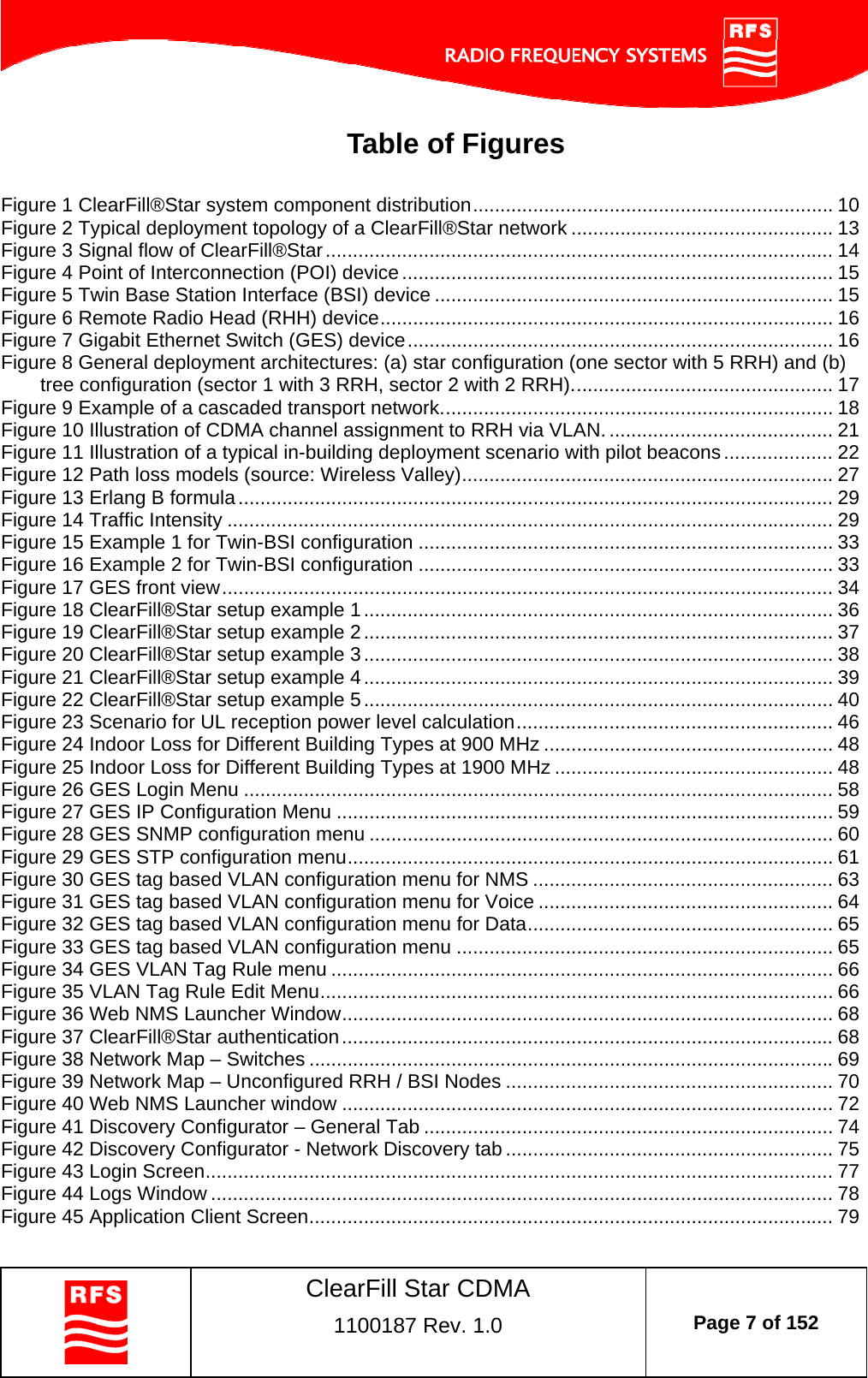
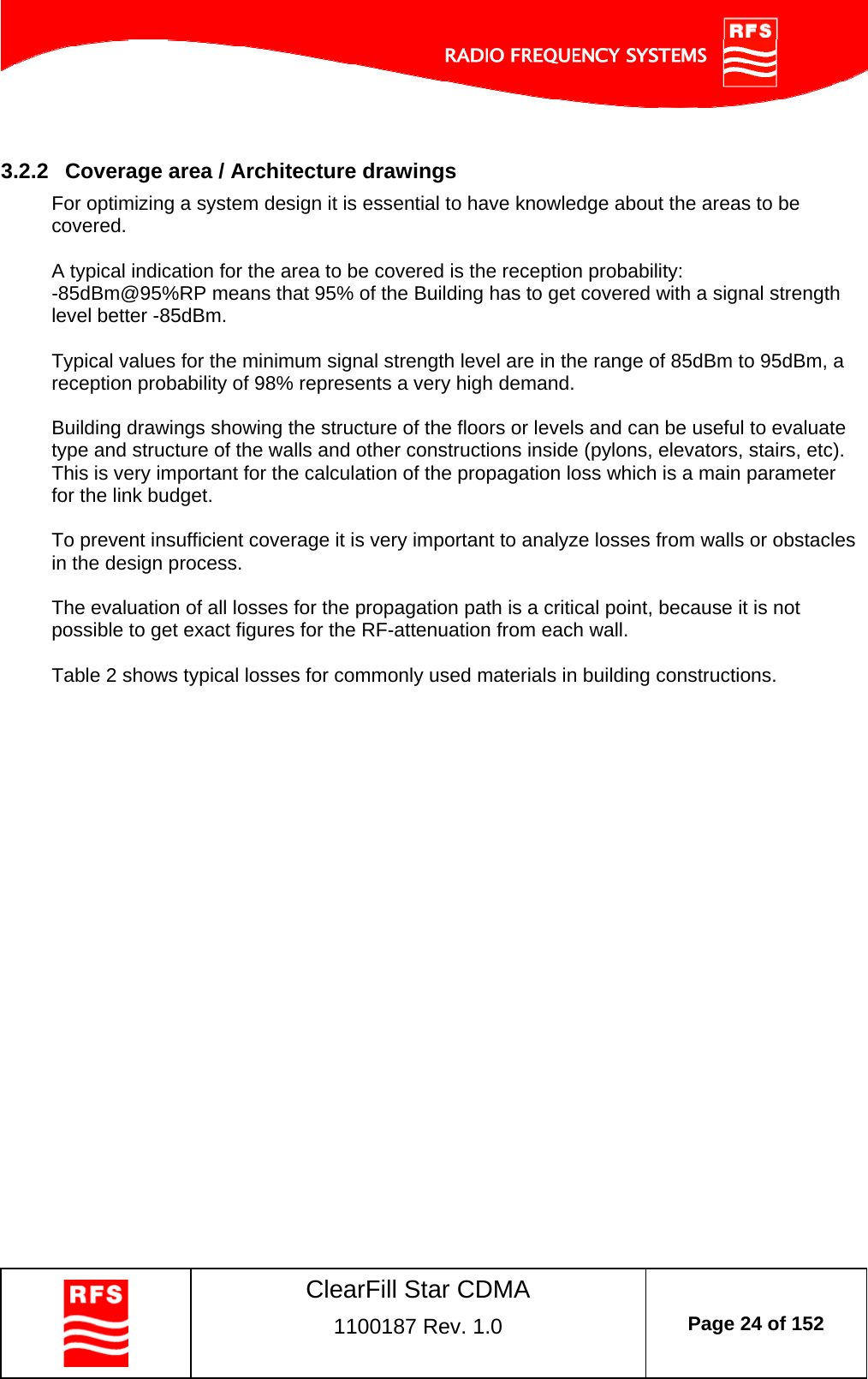
![ClearFill Star CDMA 1100187 Rev. 1.0 Page 26 of 152 Statistical models are helpful if the type of building can be classified: Model Name Path Loss Equation [dB] Retail Store PL (d) = 22 Log(3.28*d) + 20.1 Suburban Office Bldg - Open Floor Plan PL (d) = 24 Log(3.28*d) + 19.1 Suburban Office Bldg - Soft Partitions PL (d) = 28 Log(3.28*d) + 17.0 Suburban Office Bldg - Hard Partitions PL (d) = 30 Log(3.28*d) + 16.0 University PL (d) = 0.6232(d)+ 63 Motorola Cluttered PL (d) = 0.594(d) + 71 Motorola Uncluttered PL (d) = 0.3608(d) + 55 Free Space @ 894 MHz PL (d) =20 Log (3.28*d) + 21 Table 3 Typical attenuation for different building types (source: Wireless Valley) PL: Path loss (dB) d: Distance from Remote Radio Head to mobile user](https://usermanual.wiki/Radio-Frequency-Systems/W1000220/User-Guide-1205570-Page-26.png)
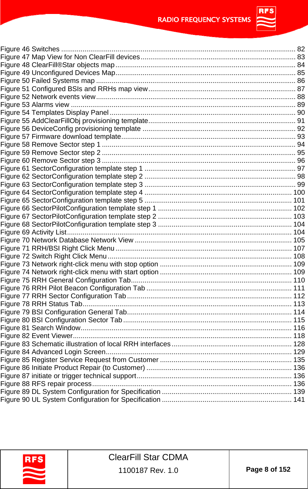
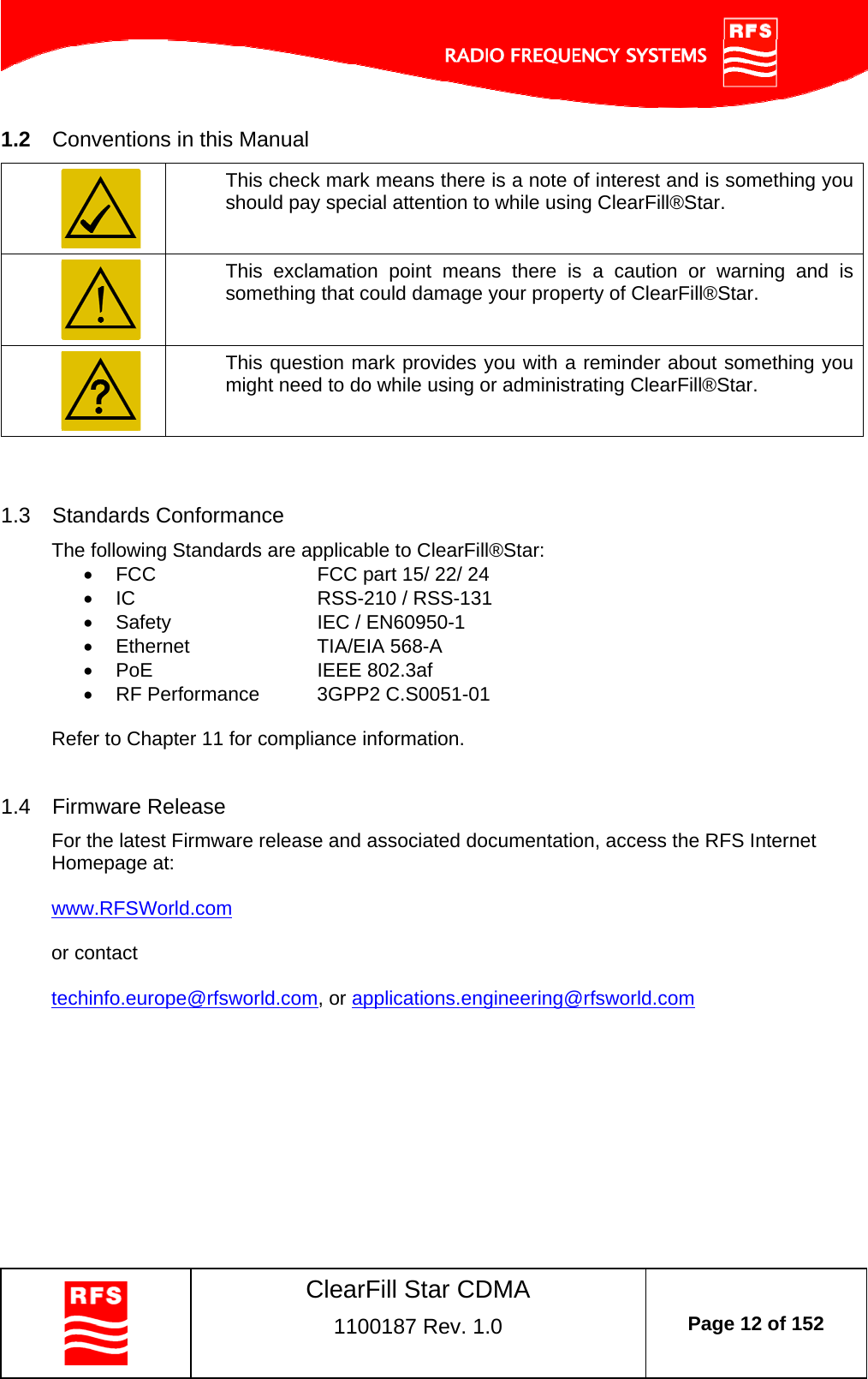
![ClearFill Star CDMA 1100187 Rev. 1.0 Page 29 of 152 3.2.4 Number of Users One CDMA channel can handle up to 56 users at the same time. A ClearFill®Star BSI supports the capacity of 1 CDMA carrier. If more capacity is required, additional CDMA carriers can be designed to overcome capacity limitations. Fairgrounds, theatres, stadium areas, meeting rooms and campuses are areas that might require capacity extension. Capacity planning has to be discussed with the network operator, responsible in general for the Base Transceiver Station. 1st step: Estimate number of subscribers 2nd step: Determine Erlangs usage In-building clients > 25 mE/sub average 3rd step: Decide quality of service (QoS) 2% blocking high Recommended 0.2 % blocking Erlang B table should be used to verify the required number of channels. The result may necessitate more than 1 RF source. Figure 13 Erlang B formula 10010110210-310-210-1Traffic Intensity in Erlang (A)Probability of Blocking (Pb[blocking])#Trunked channel, C=6#Trunked channel, C=14#Trunked channel, C=22#Trunked channel, C=30#Trunked channel, C=38#Trunked channel, C=46(0.002; 1.32) (0.002; 5.92) (0.002; 11.52)(0.002; 17.60)(0.002; 23.97)(0.002; 30.54) Figure 14 Traffic Intensity Erlang B formula CkkCbkACAblockingP0!!/](https://usermanual.wiki/Radio-Frequency-Systems/W1000220/User-Guide-1205570-Page-29.png)

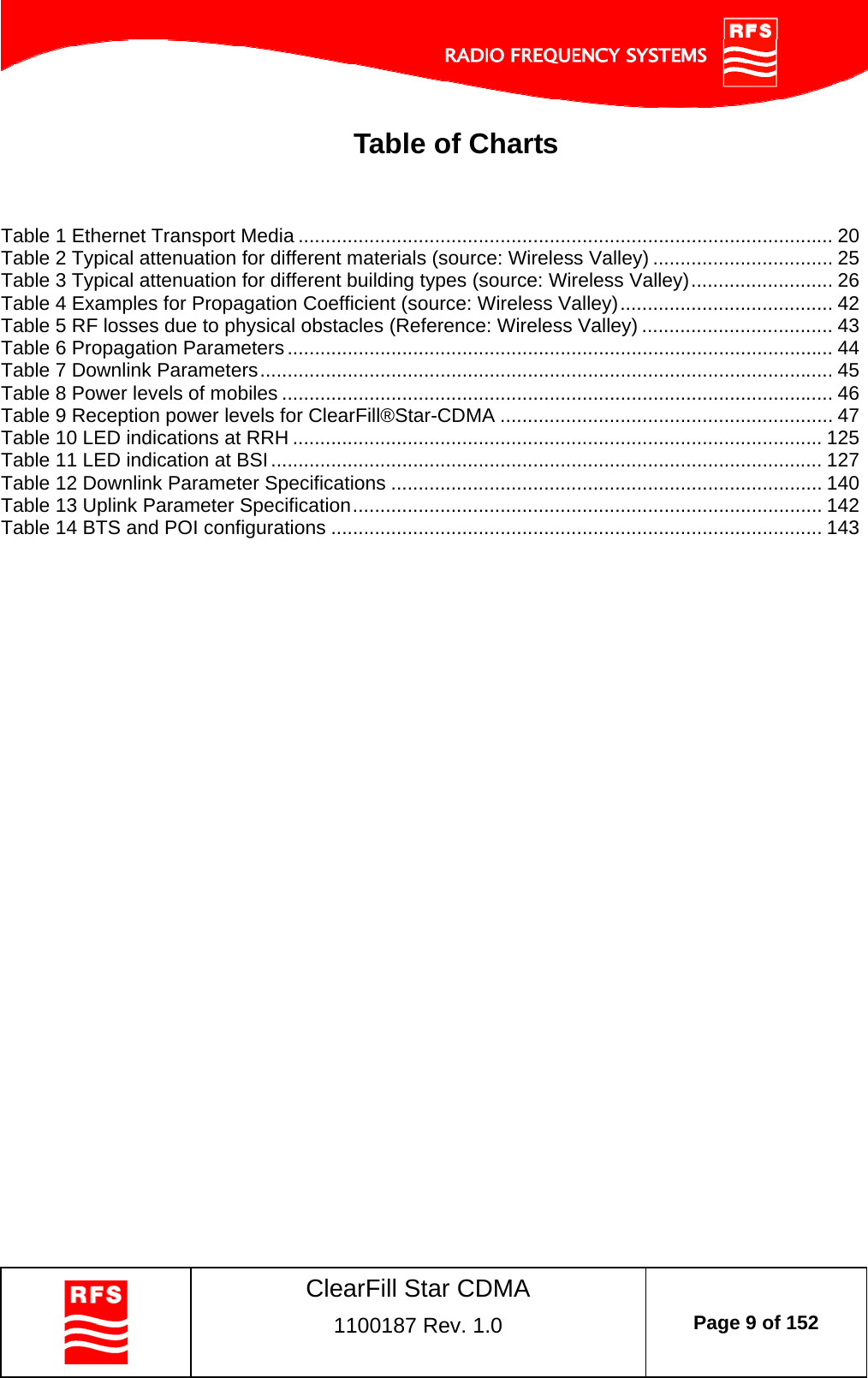
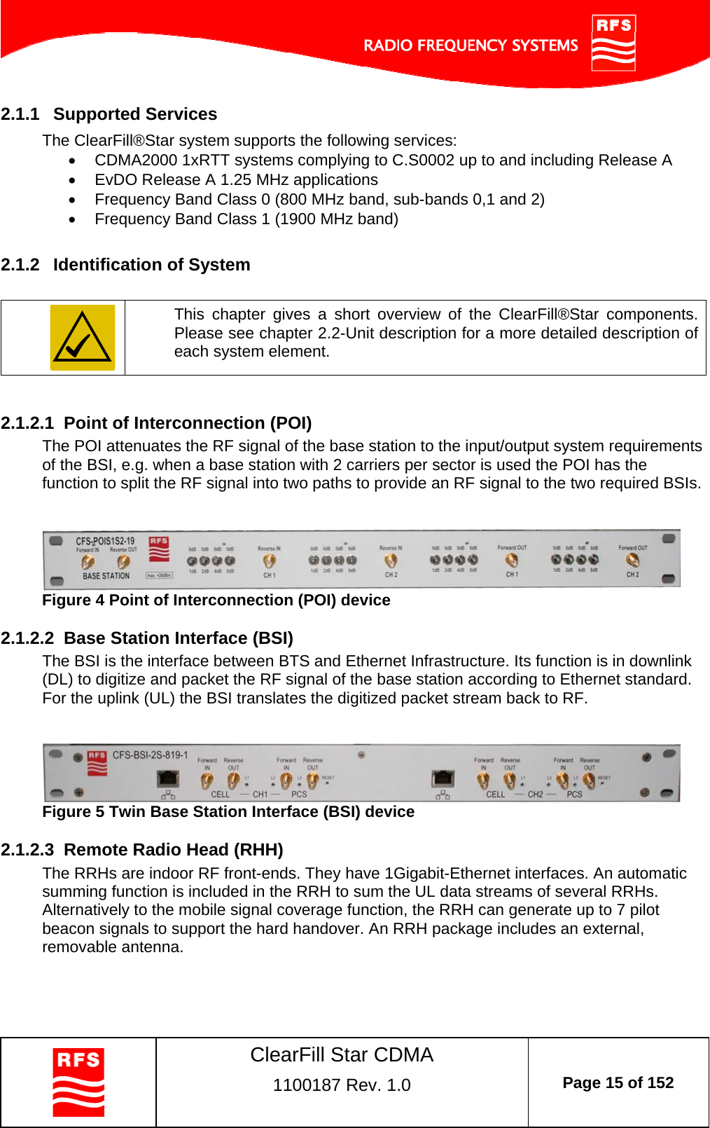
![ClearFill Star CDMA 1100187 Rev. 1.0 Page 41 of 152 3.4 Estimated RF Coverage per RRH 3.4.1 Propagation Model (Free Space Loss) A simplified model is used to calculate the propagation losses for in- and outdoor environments. Free-space propagation conditions are assumed. Obstacles penetrated in direction of transmission are causing additional RF losses. Due to relatively short ranges in buildings, line-of-sight conditions can be assumed which are interrupted by obstacles. Consequently, impact of scattering is neglected. That leads to a fading model in which the logarithmic normal portion is only to representing shadowing effects. The Raleigh fading for non-line-of-sight conditions is deliberately ignored to simplify the model. The propagation losses are calculated with the formula below: Losses [dB] = 32.4 + 20 * log10 (Frequency [GHz]) + PC * 10 * log10 (Distance[m]) + Wall losses [dB] + fading margin [dB] PC: propagation coefficient The propagation coefficient PC is dependant on the building itself and has to be adapted in order to meet the building topology. Estimates of PC are shown in Table 4.](https://usermanual.wiki/Radio-Frequency-Systems/W1000220/User-Guide-1205570-Page-41.png)