Radio Systems 050241 M024100 Transmitter User Manual Manual
Radio Systems Corporation M024100 Transmitter Manual
Manual

Invisible Fence
®
I n s t a l l - I t - Yo u r s e l f
Pet Containment
S y s t e m
I F - 1 0 0
Operation Guide
Thank you for purchasing the IF-100 Premium
Containment System.
This electronic dog containment system is among the
s a fest, most humane and effe c t i ve training products yo u
can bu y. Once your dog is properly trained, he will enjoy
hours of freedom within his new boundari e s , and you will
e n j o y the comfo rt of knowing that he has learned to stay
s a fely in your ya r d .
Please take a few minutes to read the instruction manu a l
p rior to your first use and retain the manual for future refe r-
e n c e. This instruction manual contains important progra m -
ming and set-up info rmation to help your training proceed
as successfully as possibl e. For best results, fo l l ow these
i m p o rtant ru l e s :
I M P O R TANT SAFEGUARDS
1. Obey all warnings contained in this manual.
2. The electronic dog collar is intended only for use on dogs.
Never attempt to use this product for any purpose not specifi-
cally described in this manual.
3. If you have any reason to believe that your dog may pose a
danger to others, or that it may harm itself if it is not kept from
crossing the IF-100 containment field wire, you should not rely
solely on this product to contain your dog.
4.Do not leave the collar on your dog for more than 12 hours per
day.
5. Never perform set-up procedures when the collar is on your
dog.
6. Never call or pull your dog into the containment field.
7. Keep all system components out of the reach of children.
8. The IF-100 containment system will not contain your dog
unless:
A.You train your pet as prescribed in the IF-100 training plan
(Section 7, pg.15).
B. The transmitter is on, connected to the containment loop
wire, and producing a signal along the loop wire.
C.The IF-100 collar receiver is worn properly by your dog.
D. The IF-100 collar receiver is adjusted so that the probes
are touching your dog's skin.
E. There is an adequate charge on the IF-100 collar receiver
battery. Do not use if you suspect the charge is low.
F. The 24-volt adapter is plugged into the transmitter and is
connected to a 110-volt household outlet.
9.The following precautions should always be taken:
A. Never service or install a system or any equipment during
a thunder or electrical storm.
B. Never install the transmitter where it could be exposed to
the elements, doing so will void the manufacturer's warranty.
C. Monitor the transmitter periodically to ensure that the unit
is operating properly and is producing a signal along the loop
wire.
D. Always remove your dog's collar receiver before making
any adjustments to your IF-100 containment system.
E. Use the lowest correction necessary to get the desired
behavior.
F. Allow your dog to get used to the collar before you begin
training. You want your dog to accept the collar as part of a
routine, not to associate the collar with the correction.
10. To prevent the elimination of an adequate safe zone in your
yard, any adjustments to the field width must be tested prior to
using the system with your dog.Once the field width has been
set and tested, turning the knob in a clockwise direction will
increase the correction zone and may eliminate the safe zone,
thus causing correction to be present throughout your entire
yard.If you have any questions, please contact invisible Fence
at 1-800-688-4364, before using the system with your dog.
11. Read all instructions before using this product. If you have
any questions or concerns after reading this information, contact
Invisible Fence at 1-800-688-4364.
IMPORTANT
Realize that because individual dogs have unique tempera-
ments, there is no way of knowing how your dog will react to its
introduction to this product. For the safety of your dog, initial
training should take place using a six foot or retractable leash to
keep you in control of the situation. Also realize that an aggres-
sive animal could turn against the handler upon receiving the
correction. Therefore, if you feel your dog has an aggressive
temperament and/or he has a history of aggressive behavior,
you should consult a certified animal behaviorist before using
this product. Please refer to the Section 5.B.Setting the
Transmitter Controls, Section 5.C.Important Notes about the
Collar, and Section 6.Tips for Containment Training before pro-
ceeding.
1.
IMPORTANT NOTICE: This equipment has been tested and found to comply with
the limits for a Class B digital device, pursuant to Part 15 of the FCC Rules. These
limits are designed to provide reasonable protection against harmful interference in
a residential installation.This equipment generates, uses and can radiate radio fre-
quency energy and, if not installed and used in accordance with the instructions,
may cause harmful interference to radio communications. However, there is no
guarantee that interference will not occur in a particular installation. If this equip-
ment does cause harmful interference to radio or television reception, which can
be determined by turning the equipment off and on, the user is encouraged to try
to correct the interference by one or more of the following measures:
• Reorient or relocate the receiving antenna.
• Increase the separation between the equipment and receiver.
• Connect the equipment into an outlet on a circuit different from that to which the
receiver is connected.
• Consult the dealer or an experienced radio/TV technician for help.
Caution:Changes or modifications to any component, not expressly approved by
Invisible Fence, Inc., could void the user's authority to operate this equipment.
The term "IC:" before the radio certification number only signifies that Industry of
Canada technical specifications were met.
I N T R O D U C T I O N
Your new electronic containment system contains four
major components: a wall-mount transmitter, a collar
receiver, a lightning/power surge protection module,
and boundary wire.The wall-mount transmitter gener-
ates an electronic signal that is transmitted onto the
boundary wire and is received by the collar receiver
when your dog approaches the boundary wire. When
the collar receiver senses your dog is approaching the
containment boundary, the receiver will sound a warn-
ing tone followed by a harmless, but effective electron-
ic correction. When trained properly, your dog will
quickly learn where his boundaries are. The system is
designed to contain dogs within a perimeter of up to
4175 feet (enough for a square containment area of 25
a c r e s ) . This package contains insulated wire fo r
enclosing a yard approximately one-half acre in size.
Additional boundary wire can be purchased from
Invisible Fence by calling 1-800-688-4364. The system
is also capable of containing multiple dogs simultane-
ously. Although the IF-100 is sold with one collar
receiver, additional IF-100 collar receivers can be pur-
chased from Invisible Fence by calling 1-800-688-4364.
This manual includes a Quick Start Guide for people
who are already familiar with electronic containment
systems. Additionally, a detailed description of the
transmitter, receiver and lightning protector, a detailed
installation procedure, a usage and training guide, and
a troubleshooting guide is included.
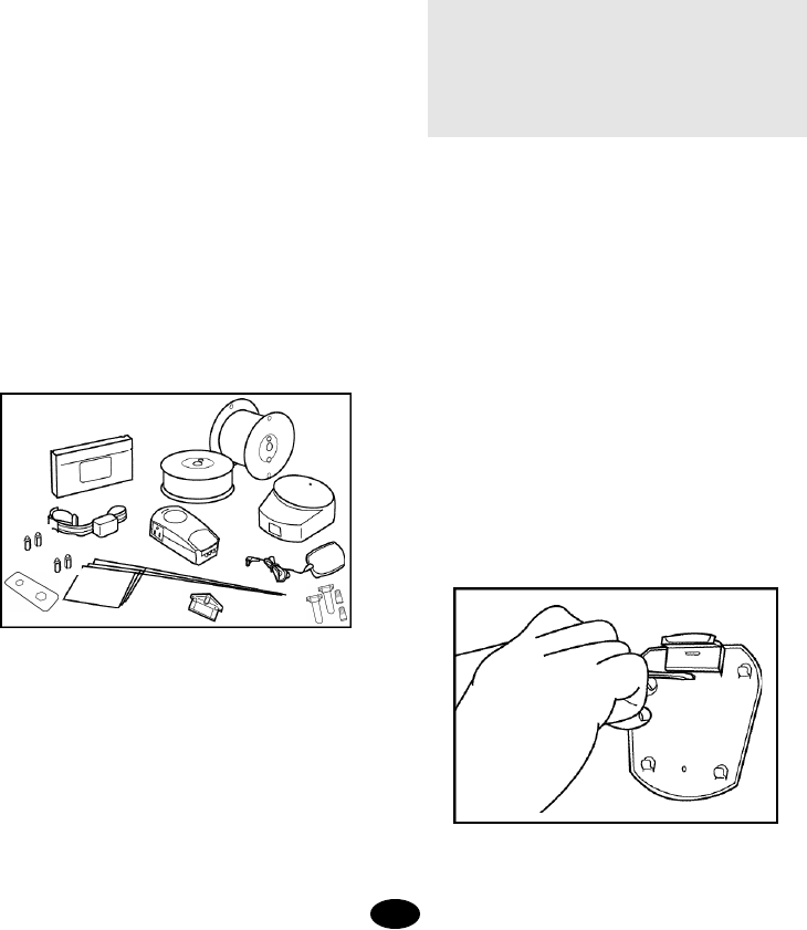
C O M P O N E N T S
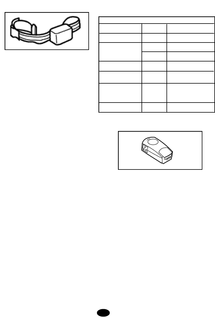
A. One waterproof collar receiver with reflective nylon
strap and quick-release buckle
B. One wall-mount transmitter with installation hard-
ware
C. One 24-volt, 400 milliamp AC adapter to power the
containment system
D. One lightning/power surge protector
E. One test lamp for testing the collar receiver
F. One hundred boundary flags
G. Green insulated containment boundary wire (700
feet)
H. White insulated pre-twisted containment wires (100
feet)
I. Interchangeable collar receiver probes for longhaired
and shorthaired dogs (one set each).
J. Black plastic training probes for use in the first train-
ing lesson.
K. Four waterproof splices (wire nut and waterproof
capsule)
L. One probe wrench
M. Owner's manual with instructional video
QUICK START GUIDE
READ THE IMPORTANT SAFEGUARDS SECTION OF
THIS MANUAL AND ALL CAUTIONS AND WARNINGS
PRIOR TO INSTALLING AND USING THIS SYSTEM.
IT IS RECOMMENDED YOU READ THE ENTIRE
MANUAL PRIOR TO INSTALLATION OR USE OF THIS
SYSTEM.
This Quick Start Guide is provided for people who are
already familiar with electronic containment systems. It
also serves as a quick visual index to the detailed instal-
lation procedure included in this guide.If you find you
need more detail while using this Quick Start Guide,
simply refer to the procedure section referenced for
detailed instructions.
1. Layout your containment boundary(See Section
4.A, pg 7 for details)
Sketch your yard on a piece of graph paper and decide
where you would like to contain your dog. Section 4.A.
shows some sample layouts and provides some helpful
design tips. Before you decide where to bury your con-
tainment wire have your utility companies mark utility
lines
2. Install the Wall-Mount Transmitter (See Section
4.B, pg 8 for details)
Select a dry, indoor location for the wall-mount trans-
mitter that is within five feet of a standard, grounded
110-volt household outlet.Attach the transmitter mount-
A. B.
H. G.
M.
D.
F.
L. E.
I. C.
K.
2.
J.
ing plate to the wall using the supplied hardware.
Making sure the POWER switch on the transmitter is in
the OFF position, place 8 AA alkaline backup batteries
(optional, but recommended) in the battery compart-
ment on the back of the transmitter. Snap the transmit-
ter onto the mounting plate.Remember to mount your
transmitter in a location where you will be able to hear
any alarms.
3.Set Up the Collar Receiver (See Section 4.C, pg 9
for details)
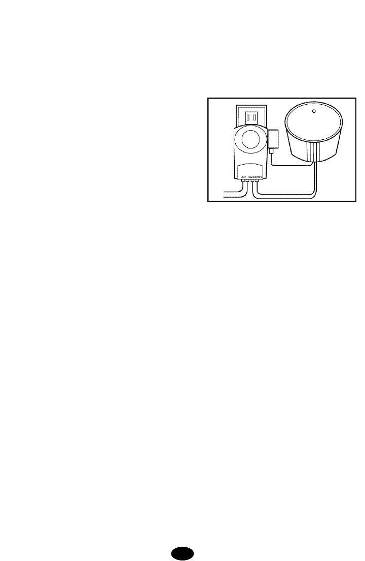
In preparation for setting up your boundary loop, the
r e c h a r g e a ble collar receiver must be given a full
charge. Set the transmitter POWER switch to OFF, set
the FIELD SIZE switch to SM, turn the FIELD WIDTH
knob to MIN, and position the collar receiver in the
charging cradle located on the top of the wall transmit-
ter. Orient the light on the collar receiver toward the end
of the charging cradle marked with an arrow. Cut a
short piece of the green boundary wire (about 6 inches)
and strip about 3/8 inch of insulation from both ends.
Insert the wire ends into the LOOP terminals on the
transmitter. Plug the AC adapter into the power jack on
the transmitter and plug the adapter into a nearby 110-
volt household outlet. Set the transmitter POW E R
switch to the ON position to charge the collar. The
transmitter light will flash green approximately every
two seconds while charging. A full charge requires 14
hours. When charging is complete, the light on the
transmitter will appear solid green. If the green light is
not blinking, make sure the receiver is oriented proper-
ly in the charging cradle, be sure the transmitter is
turned on and check all connections. After the receiver
has been fully charged, set the POWER switch to the
OFF position, remove the short piece of boundary wire,
and unplug the AC adapter from the wall outlet.
NOTE: The transmitter will not recharge the collar
receiver if the loop wire is not installed.
4. Plan the BoundaryWire Placement (See Section
4.D, pg 9 for details)
For the system to work properly, the wire must make
one continuous loop.When placing the wire, keep in
mind that you will want at least an 8- to 12-foot contain-
ment field (8 to 12 feet on each side of the wire). Use
the pre-twisted wire from the transmitter to the Lightning
Protector and from the Lightning Protector out to the
exterior loop wire.
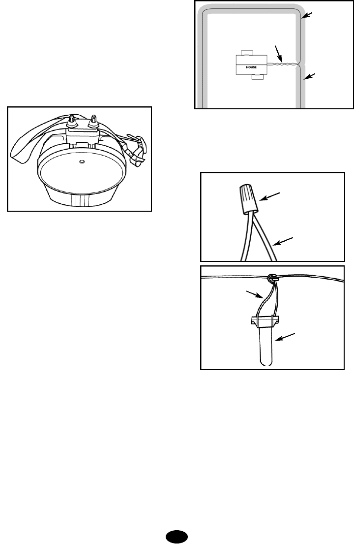
5.Place the Wire (See Section 4.E, pg 10 for details)
Place your boundary wire on top of the ground following
the tips listed in Section 4.D.Use the supplied water-
proof splices to make proper connections. To use the
splices, strip 5/8” of insulation from the ends of the
wires you are joining.With the ends of the wires even
and together, place the wire nut over the wire ends and
turn the wire nut clockwise until it is securely fastened.
Snap open the hinged lid of the gell filled capsule and
insert the wire nut as deeply as possible into the water-
proof gel.Snap the lid shut, making sure the wires exit
the splice on either side.Tie a knot in the wires as
shown in the diagram to prevent them from pulling out
of the gell filled capsule when the wire is buried.
DO NOT BURY THE WIRE UNTIL YOU HAVE TESTED
3.
Twisted pair to transmitter;
cancels containment field
Boundary wire
Containment
field (invisible);
8 - 12’width;
follows loop of
wire along
entire length
Wire nut
Wire
Gell filled
capsule
Wire
THE SYSTEM AND ARE SURE IT IS WORKING
PROPERLY. TAKE CARE NOT TO NICK OR SCRAPE
THE WIRE INSULATION DURING INSTALLATION. AN
INTERMITTENT SIGNAL OR NO SIGNAL MAY
OCCUR.
6. Make the Final Connections (See Section 4.F, pg
10 for details)
Determine where the boundary wire will enter the build-
ing and drill a 1/4 inch hole through the wall, making
sure there are no wires, cables or pipes in the area you
are drilling. Plug the Lightning Protector into a nearby
standard, grounded 110-volt household outlet. Use the
supplied white twisted pair wire to connect your bound-
ary wire to the LOOP terminals on the Lightning
Protector and to connect the TRANSMITTER terminals
on the Lightning Protector to the LOOP terminals on the
transmitter. Making sure the power switch on the trans-
mitter is in the OFF position, plug the power adapter
into the Lightning Protector and plug the other end of
the power adapter into the POWER jack on the trans-
mitter. Set the FIELD SIZE switch to SM if you are
using less than 1000 feet of boundary wire or to LG if
the boundary wire is longer than 1000 feet.Verify that
your dog is not wearing the collar and no one is touch-
ing the collar receiver probes, set the FIELD WIDTH
knob to MIN and slide the transmitter POWER switch
into the ON position. A green indicator light should illu-
minate on the transmitter indicating a properly connect-
ed boundary loop. If the green indicator light does not
illuminate, refer to the Section 8, pg 16 to troubleshoot
the installation.
7.Test the system (See Section 4.G, pg 11 for details)
Make sure no one is touching the collar receiver
probes. Set the transmitter's FIELD WIDTH adjustment
knob to the 9 o'clock position and set the transmitter
POWER switch to the ON position. Attach the test light
to the probes and slowly walk the collar receiver toward
the center of a 50 foot straight section of the boundary
wire with the collar receiver held at the height of your
dog's neck with the probes pointed upward. Listen for
the warning sound and watch for the test light to illumi-
nate. The containment field should extend at least 8 to
12 feet on each side of the wire. To increase the field
width, rotate the FIELD WIDTH adjustment knob clock-
wise and recheck the distance the signal is broadcast-
ing from the wire.To decrease rotate Field Width count-
er clockwise; recheck.Repeat this procedure until you
are satisfied with the width of the correction field
throughout the installation.
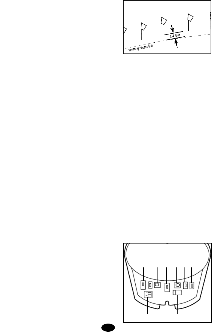
8. Bury the BoundaryWire and Place Flags (See
Section 4.H, pg 12 for details)
Turn off the transmitter and disconnect the AC adapter
from the Lightning Protector. Bury the wire about 3 to 4
inches deep where the wire first enters the ground near
the transmitter and continue around the path of the loop
wire at a depth of at least 1 inch (you may wish to rent
a slit trencher for this purpose). Be careful you don't
nick the wire insulation as you place the wire in the
ground. Leave some slack in the wire to compensate
for expansion and contraction due to tempera t u r e
changes. Repeat the test from Step 7 until you are sat-
isfied with the field width setting.As you approach the
boundary wire, place a flag 3 to 4 feet inside the point
where the receiver first detects the warning sound.
Continue placing the flags at 6 to 8 foot intervals around
the entire containment area using this technique. Don't
forget to caulk and seal the interior and exterior holes
you made for the wire to prevent damage from mois-
ture. You are now ready to proceed with Sections 5
through 7 for detailed instructions on using the system
and training your dog.
SECTION 1.
THE WALL-MOUNT TRANSMITTER
The wall-mount transmitter is your system's control cen-
ter and works with the collar receiver and boundary wire
to keep your dog safely contained within an area you
select. The front cover of the wall transmitter lifts up to
reveal switches that will customize your containment
system.
1. 2. 3. 4. 5. 6. 7.
8. 9.
4.
Containment Field
Safe Zone
1.Correction Level - Positioning the STIM LEVEL switch to
LOW, MED, or HI selects the correction level your dog
receives as he enters the containment field. The LOW setting
administers a 2-second warning sound, followed by a low
level of correction if your dog does not return to a safe area.
The MED setting administers a 2-second warning sound, fol-
lowed by a medium level of correction if your dog does not
return to a safe area. The HI setting delivers an immediate
high level of correction without any warning sound prior to the
correction.
2.Field Size-The FIELD SIZE switch allows you to select the
appropriate setting based on the size of your installation. The
SM setting is for properties using 1000 feet of wire or less.
The LG setting is for all installations using over 1000 feet of
wire.
3. Field Width Adjustment -The FIELD WIDTH knob con-
trols the distance from the wire that your dog will receive the
warning sound and correction. With the supplied test light on
the collar receiver, always test this function at multiple loca-
tions in your containment area before putting the collar on
your dog.
4.Charge Reminder -The REMINDER switch allows you to
select a reminder interval of 60 (Labeled A) or 30 (Labeled B)
days or turn the function OFF. The timer starts when the col-
lar receiver is removed from the charger. This switch should
be set at a time interval that will remind you to check the col-
lar receiver and verify that it has an adequate charge to con-
tain your dog. You should check the collar receiver for a low
battery indication before you put it on your dog.
5.Alarm Volume -The volume of the alarm indicator can be
adjusted using the ALARM VOLUME knob.
6. Power -The containment system can be turned on or off
by sliding the POWER switch to the ON or OFF position.
7. Battery Backup Monitor - If power to the home is inter-
rupted, backup power is provided by installing eight AA
Alkaline batteries (not included) in the holder on the backside
of the transmitter housing. Only use Alkaline batteries. The
Battery Backup Monitor will sound to indicate the AA batteries
need to be changed. This alarm can be turned ON or OFF by
the switch inside the transmitter. For the safety of your dog,
this feature should be turned on and the batteries kept in
working order at all times.
8.Wire Terminals-The two containment loop wires from the
Lightning Protector connect to the wall transmitter through the
bottom of the case. They slide into the terminal block located
inside the transmitter in the area marked LOOP. When the
containment loop is properly connected, the green transmitter
light will illuminate to indicate the power is on and the loop
wires are properly connected
9. Power Connection - The power for the containment sys-
tem is provided by a supplied 24-volt, 400-milliAmp AC
adapter. This adapter plugs into the supplied Lightning
Protector, which in turn is plugged into a nearby 110-volt
household outlet. The other end plugs into the power con-
nector located inside the transmitter through the bottom of the
transmitter case.
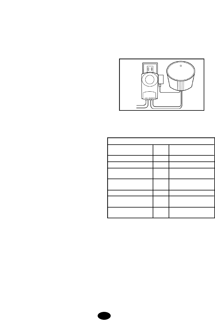
10.Indicator Light and Alarm -The light located on the front
face of the transmitter will indicate the following conditions:
Notes:
1. Alarm tone twice per second.
2. Three one second reminder tones every minute. Reset by
placing the receiver on the charge cradle for more than 5 min-
utes. May be turned off by placing charge REMINDER switch
in the OFF position.
3. Alarm tone once per second when BACKUP BATTERY
monitor switch is set to ON.
4. Alarm tone once per second.May be turned off by placing
switch in OFF position.
A chart of the indicator light and alarm conditions has been
placed inside the transmitter cover for your convenience.
5.
IF-100 TRANSMITTER STATUS INDICATIONS
STATUS LIGHT ALARM CONDITION
TONE
SOLID GREEN NO POWER ON / SYSTEM OK
FLASHING GREEN NO RECEIVER CHARGING
FLASHING RED YES1BOUNDARY WIRE BROKEN
OR DISCONNECTED
FLASHING RED AND GREEN YES2RECEIVER RECHARGE
REMINDER
FLASHING YELLOW YES3BACKUP BATTERIES LOW
NONE YES4AC POWER DISCONNECTED
OPERATING ON BATTERY
NONE NO TRANSMITTER IS OFF OR
POWER IS DISCONNECTED
SECTION 2.
THE COLLAR RECEIVER
The collar receiver is waterproof, rechargeable, and can
be mounted on any non-metal strap.The probes are
available in long and short lengths to be used on long-
haired and shorthaired dogs, respectively.
Note: The collar receiver is always on and ready to
respond to the containment field when the battery is
properly charged.
A.Special Features to Increase the Effectiveness of
the System
1.The Warning Tone -With the STIM LEVEL switch
set to LOW or MED your dog will hear a two second
warning tone when he reaches the edge of the contain-
ment field in the yard.If your dog does not return to the
safe part of the yard, he will receive a continuous cor-
rection (at the Low or Medium correction level switch
setting) until he re-enters the safe part of the yard.
Note: If the STIM LEVEL switch is set on HIGH, there
will be no warning tone prior to the correction.
2. Run-Through Prevention - Special features are
incorporated in the IF-100 system so your dog cannot
"run-through" the containment field without activating a
strong correction. The receiver automatically increases
the correction when your dog continues more than 1/3
of the way through the containment field, regardless of
the transmitter correction level setting. For example, if
the signal is detected 12 feet from the wire and your dog
enters the containment field, this feature is activated
when he is approximately eight feet from the wire. At
this point, your dog automatically receives the highest
level of correction for a minimum of three seconds.
3.Over-Correction Prevention - In the unlikely event
that your dog becomes "trapped" in the containment
field, this feature limits correction duration to 10 sec-
onds. The system shuts off for 10 seconds before
resuming correction for another 10 seconds. This pat-
tern will repeat for a maximum of three cycles, a dura-
tion of 60-seconds.
The light on the collar receiver will pulsate red when
correction is delivered, appear solid green when cor-
rection is locked out, and flash yellow if the 60-second
period has expired and the dog remains in the contain-
ment field.
B.Receiver Indicator Lights
The receiver includes an indicator light and a tone gen-
erator that allow the user to distinguish the various
operational conditions of the receiver.These conditions
are summarized in the following table:
SECTION 3.
THE LIGHTNING PROTECTOR
Your system includes a lightning protection unit, which
helps protect the transmitter from electrical powe r
surges and lightning strikes near your boundary loop. A
nearby lightning strike can induce damaging high volt-
age on the boundary wire loop and electrical power
lines, which can damage an unprotected containment
transmitter. The lightning protector protects your sys-
tem in two ways. Lower level voltage spikes from near-
by lighting strikes and power line surges are sup-
pressed to a level that will not damage your transmitter.
Severe lightning strikes may result in damage to the
Lightning Protector, which is designed to be a sacrificial
link in the system. Your transmitter will remain
u n h a rmed and your Lightning Protector can be
replaced under the terms of the Lightning Protector life-
time warranty (see Limited Warranty Section pg. 22).
System components which are not properly protected
by the supplied Lightning Protector will not be covered
for lightning damage under the warranty (see Limited
Warranty Section pg 22).Your Lightning Protector has a
green power light that indicates the unit is receiving
household power.
Note that this Lightning Protector is specifically designed for electronic dog
containment systems and will not protect other kinds of equipment against
lightning damage or AC surges.
INDICATOR LIGHT
GREEN FLASHING
(ONCE EVERY SECOND)
GREEN PULSATING
RED PULSATING
RED FLASHING
(ONCE EVERY 2 SECONDS)
SOLID GREEN
YELLOW FLASHING (ONCE
EVERY 2 SECONDS)
NONE
CONDITION
COLLAR IS READYTO RESPOND
TO THE CONTAINMENT FIELD
WARNING TONEIS OCCURRING
ENTRY LEVEL CORRECTION IS
BEING DELIVERED
RUN-THROUGH CORRECTION IS
BEING DELIVERED
RECEIVER BATTERY IS LOW
CORRECTION IS LOCKED OUT
(OVERCORRECTION
PREVENTION IN EFFECT)
OVER-CORRECTION
PREVENTION HAS EXCEEDED
THREE CYCLES ( S T I M U L ATION
IS LOCKED OUT UNTIL YOUR DOG
RETURNS TO THE SAFE ZONE)
RECEIVER BATTERY IS
COMPLETELY DISCHARGED
6.
TONE PITCH
NONE
INTERMITTENT
LOW PITCH
INTERMITTENT
MEDIUM PITCH
INTERMITTENT
HIGH PITCH
NONE
CONTINUOUS
LOW PITCH
NONE
NONE
SECTION 4.
I N S T ALLING THE IF-100 CONTA I N M E N T
S Y S T E M
A. Creating the Layout -When selecting a layout for your
containment system, keep it simple;complex installations are
more difficult for dogs to learn. Here are some key points to
remember:
• Consider all the obstacles -- gardens, play areas, driveways,
sidewalks, pools, porches, and water crossings.
• Utility companies must be contacted to mark the buried util-
ity lines.
• To avoid future wire breaks caused by landscaping efforts,
the lawn should never be aerated in the vicinity of the con-
tainment wire.
• For your dog's safety, it is recommended to keep the con-
tainment wire at least ten feet from the street.
• Keep in mind that you will want at least an 8- to 12-foot con-
tainment field (8 to 12 feet on each side of the wire).
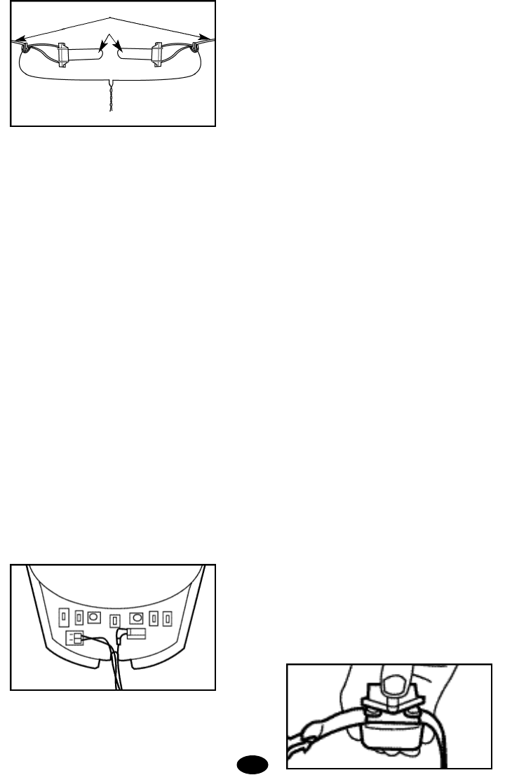
• It is possible to cancel the containment signal in a portion of
the containment loop by twisting the wires as illustrated
below. This allows the containment wire to cross safe areas
of the yard without causing your dog's collar receiver to deliv-
er correction. A spool of pre-twisted wire is included in your
system for this purpose.If you need additional twisted wire,
the single containment wire (green) can be twisted at 3 to 4
twists per foot to achieve the same result.
Described below are several popular containment installa-
tions. You may find these helpful in planning the layout that
will best meet your needs.
The perimeter loop is the most common installation. The wire
is placed just inside the property line and usually forms a
square or rectangle.
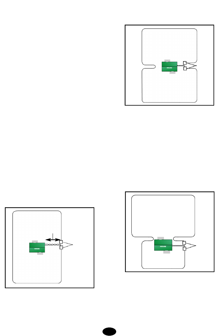
The hourglass design allows your dog to be contained in
either the front or back yard. This layout is similar to the
perimeter loop, except the wire is run close to the house on
two sides. When positioning the wire parallel to itself as it
goes toward the side of the house from the perimeter, keep it
a distance equal to the field width plus three feet from itself.
To prevent your dog from playing in the side yard, keep the
wire a distance equal to the field width less one foot from the
house.
The back yard loop encloses the back yard and uses the back
portion of the house as part of the barrier. After laying wire on
the three sides of the back yard, bring the wire a distance of
the field width less one foot from the back corner of the house
to prevent your dog from playing in the side yard. When run-
ning the containment wire parallel to the side and around the
front of the house, keep the wire a distance from the house
equal to the field width plus three feet to prevent sending a
corrective signal through the walls of the house. Continue
placing wire at this distance from the home until it reaches the
entry hole leading to the wall transmitter. Encircling the house
contains your pet if he bolts out of the front entrance or the
garage door. These areas are usually not flagged.
A double loop installation will provide a barrier in the back
yard without running wire into the front yard. Beginning at the
wall transmitter, lay the containment wire to the nearest
perimeter and proceed around the back yard until you are at
the opposite side of the house.When at a distance from the
corner of the house equal to the containment field width less
one foot, do a hairpin turn and continue positioning the wire a
distance of the field width plus three feet away from itself.
7.
splice
containment signal
cancelled in this area
splice
splice
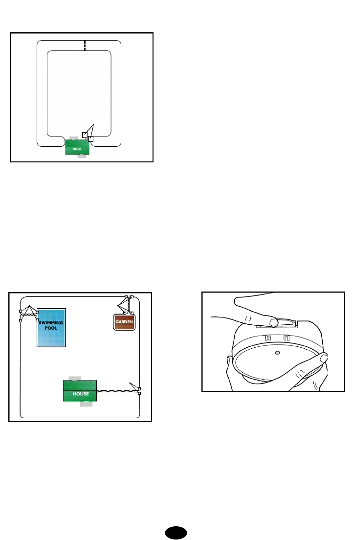
Proceed around the back yard until you return to the opening
leading to the wall transmitter. This design will keep the back
entrances to the house free from corrective signals.
Your containment installation can be customized to protect
areas such as gardens, pools, and specific landscaping. To
accomplish this, encircle the protected area with containment
wire. Cut a length of white twisted wire equal to the distance
between the protected area and the containment perimeter.
Use waterproof splices to connect the twisted wire to the con-
tainment wire at the perimeter and at the protected area. The
containment signal is cancelled where the twisted wire is
located thus allowing your dog to run around the garden or
pool without receiving correction. The containment signal
around the protected area will keep your dog out just as the
perimeter containment wire keeps him in.
Once you are satisfied with the layout of your containment
system, it is time to choose a proper location for the wall-
mount transmitter.
B.Installing the Wall-Mount Transmitter
1. Select a Location for the Wall-Mount Transmitter.
Select a location for the wall-mount transmitter that is within
five feet of a standard, grounded 110-volt household outlet
and will provide easy access to an exterior wall where the
containment wire can penetrate.When selecting a location,
keep in mind that you will need easy access to the transmitter
for recharging the receiver. If possible, avoid plugging the unit
into an outlet that is protected by a ground fault current inter-
rupter (GFCI). The GFCI will not interfere with the normal
operation of your system, but in rare cases lightning strikes
may cause a GFCI outlet to trip (disconnect power), and you
would need to reset the GFCI to restore household power to
the system. If you must use a GFCI protected outlet, make
sure you take advantage of the system's battery backup fea-
ture (described in Step 3 of this procedure). Also check the
location where you want to bring the outside wires through the
wall and into the wall transmitter to avoid electrical or tele-
phone wires, television cables, or water pipes.Even after
checking, there may be unknown wires or pipes inside the
wall. Therefore, consider going through a windowsill or door
frame whenever possible. Mark the desired location with a
pencil.
The transmitter may be mounted on a hollow wall or directly
to a wall stud using the provided mounting hardware. The
wall-mount transmitter must be located in a dry, enclosed area
where the temperature range will be between 32˚F and 110˚F
(0˚C to 45˚C). Preferable locations are the garage, laundry
room, office, or finished basements.These areas are used
frequently, so the system information generated by the wall
transmitter is likely to be checked more regularly. For ease in
monitoring this information, mount the transmitter at least four
feet from the floor.
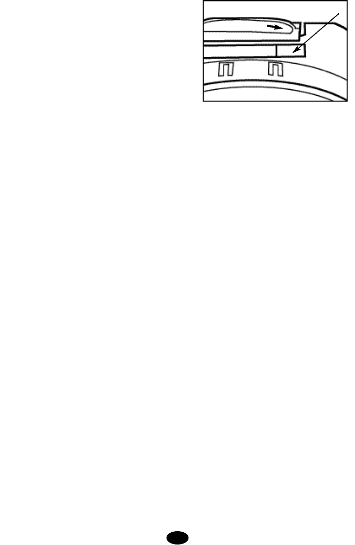
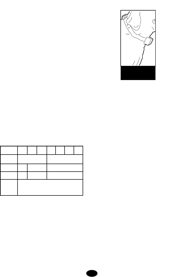
2. Install the Mounting Plate.
Remove the mounting plate from the back of the transmitter
by lightly depressing the dot on the top tab (see illustration)
and lifting the transmitter housing off the mounting plate.
Making sure the mounting plate is level, use the mounting
plate as a template to transfer the position of the two mount-
ing holes onto the mounting location by tracing the holes with
a pencil.
Make sure there are no electrical wires or other objects direct-
ly behind the mounting-hole locations that might be damaged
when the mounting screws are installed.
For hollow wall installations, drill 1/4-inch diameter holes at
the marked locations and tap in the hollow wall fasteners with
a hammer. For installation of mounting screws directly into a
8.
splices splices
splice
6 ft.
splices
wall stud, drill 3/32-inch diameter pilot holes at the marked
locations.
Fasten the mounting plate to the mounting location using the
supplied screws.
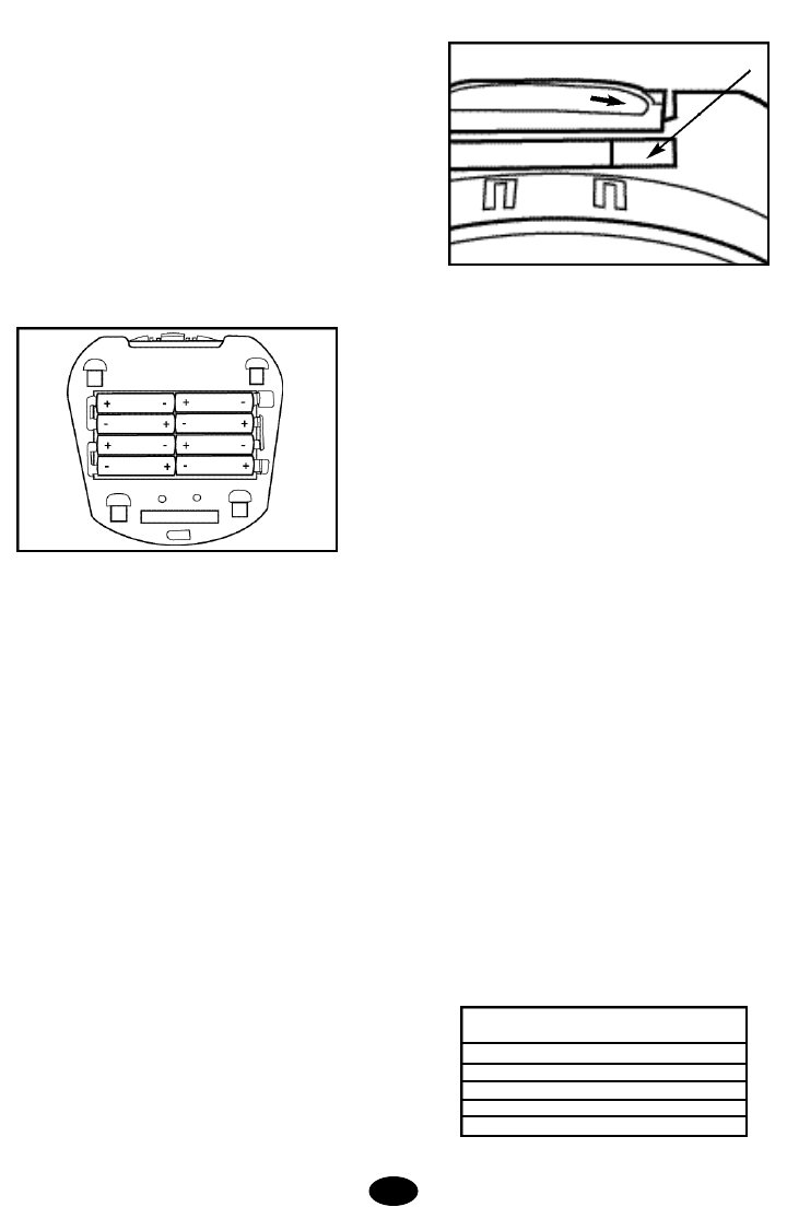
3 . Install Power Backup Batteries (Optional bu t
Recommended).
Your system's transmitter includes the means for installing
backup batteries so the system will remain functional for a lim-
ited time, even if your home experiences a power failure.
Set the POWER switch under the transmitter's front cover to
the OFF position. With the mounting plate removed, turn the
transmitter over to reveal the backup battery compartment.
Install eight (8) AA alkaline batteries according to the polarity
markings inside the battery compartment.
Set the BATTERY BACKUP MONITOR switch to the ON posi-
tion. If you choose not to install the backup batteries, set the
BATTERY BACKUP MONITOR switch to the OFF position to
disable the low battery alert.
4. Install the Transmitter on the Wall.
Snap the transmitter onto the mounting plate.At the pre-
marked location where the containment wires will enter the
home, drill a 1/4-inch hole from the inside through the wall or
corner of a windowsill or door frame. A slight downward angle
will help the wire to curve downward outside and keep water
out.
A masonry bit can be used to drill through cinderblock or
through the joint crack on brick or stone walls. A regular 1/4-
inch drill bit can be used if the house is of wooden construc-
tion with vinyl or aluminum siding. In these cases, you may
want to drill from the outside for exterior aesthetics.
C.Setting Up the Collar Receiver - In preparation for setting
up your boundary loop, the rechargeable collar receiver must
be given a full charge.
1. Set the transmitter POWER switch to OFF.
2. Set the FIELD SIZE switch to SM.
3. Turn the FIELD WIDTH knob to MIN.
4.Position the collar receiver in the charging cradle located on
the top of the wall transmitter.Orient the light on the collar
receiver toward the end of the charging cradle marked with an
arrow and identified on the label.
5. Cut a short piece of the green boundary wire (about 6 inch-
es long) and strip about 3/8 inch of insulation from both ends.
Insert the wire ends into the LOOP terminals on the transmit-
ter.NOTE:This wire is temporarily installed to perform the ini-
tial set up charging of the collar receiver.The transmitter will
not charge the collar receiver if the loop wire is not installed.
6. Plug the AC adapter into the POWER jack on the transmit-
ter and plug the adapter into a nearby 110-volt household out-
let.
7. Set the transmitter POWER switch to the ON position to
charge the collar. The transmitter light will flash green approx-
imately every two seconds while charging and a high fre-
quency charge tone will be heard from the transmitter. If the
green light is not blinking, make sure the receiver is oriented
properly in the charging cradle, be sure the transmitter is
turned on and check all connections.A full charge requires
14 hours. When charging is complete, the light on the trans-
mitter will appear solid green. After the receiver has been fully
charged, set the POWER switch to the OFF position, remove
the short piece of boundary wire and unplug the AC adapter
from the wall outlet.
D.Planning the Placement of the BoundaryWire -With the
wall transmitter installed and the hole drilled for the wires,
begin positioning the boundary wire according to your layout.
Listed below are some helpful instructions and tips.
1. Amount of Wire
Your system includes 700 feet of boundary wire and 100 feet
of pre-twisted wire. For yards requiring more wire, boundary
kits are available from Invisible Fence at 1-800-688-4364. It
is important that the same gauge wire be used throughout the
installation. Here are some examples of wire coverage:
The above figures assume a rectangular layout and actual
footage may vary.
9.
collar receiver light to this end
Acres Linear Feet
Needed
1 850
2 1200
3 1500
4 1700
5 1900
2. Placing the Wire
For the system to work properly, the wire must make one con-
tinuous loop. The signal is transmitted from one terminal of
the transmitter, through the wire, and back to the other termi-
nal. When placing the wire, keep in mind that you will want at
least a 8- to 12-foot containment field (8 to 12 feet on each
side of the wire). Avoid making passageways too narrow or
your dog may be hesitant to use them (i.e.along the sides of
a house).
3. Using Twisted Wire
Use the twisted wire from the transmitter to the Lightning
Protector and from the lightning protector out to the exterior
loop wire. The twisted wire cancels the signal and allows your
dog to cross this area. It can also be used to connect the con-
tainment system to internal areas that should be protected
like gardens, pools, and special landscaping.
4. Rounding Corners
Use gradual turns at the corners with a minimum of 2.5-foot
radius. This will produce a more consistent containment field
and avoid confusing your dog in these areas.
5. Crossing Driveways, Sidewalks, and Water Features
When crossing an asphalt driveway, make a 1/2-inch deep cut
across the driveway using a circular saw and masonry blade.
Place the wire in the crack and seal with asphalt sealant. On
driveways and sidewalks, if an expansion joint is available,
simply place the wire in the joint and seal with an outdoor
caulk. When crossing gravel, bury the wire at least 3 inches
deep. Use a piece of garden hose or plastic PVC piping to
protect the wire.In water, anchor the wire with large rocks.
Protect the wire with a piece of garden hose or plastic PVC
piping. The wire does not have to be buried, but to minimize
the potential for wire damage, it is advisable to bury it at least
one inch underground.
E.Placing the BoundaryWire
1. Listed below are important tips about placement and burial
of the boundary wire:
• Do NOT bury the loop within 10 feet parallel to electrical,
telephone, cable TV, or other buried wire in the yard.
• Do NOT bury one section of wire within 10 feet of another
section or the signal may cancel.
• Do NOT bury your wire within 10 feet of a neighboring con-
tainment system's boundary wire.
2. Position the Wire in the Yard
The above recommendations may cause you to modify your
layout, but it will be time well spent. When your layout is final-
ized, place the wire around your property according to your
diagram. The wire loop should begin and end at a perimeter
location closest to the location of the transmitter. This will min-
imize the amount of twisted wire needed to connect the
boundary loop wire to the transmitter.
DO NOT BURY THE WIRE UNTIL YOU HAVE TESTED THE
SYSTEM AND ARE SURE IT IS WORKING PROPERLY.
TAKE CARE NOT TO NICK OR SCRAPE THE WIRE INSU-
LATION DURING INSTALLATION. AN INTERMITTENT SIG-
NAL OR NO SIGNAL MAY OCCUR.
F. Making the Final Connections
After the transmitter has been installed on the wall and the
boundary wire is in place, the final connections must be
made.
1. Installing the Lightning Protector
If possible, avoid plugging the unit into an outlet that is pro-
tected by a ground fault current interrupter (GFCI). The GFCI
will not interfere with the normal operation of your system, but
in rare cases lightning strikes may cause a GFCI outlet to trip
(disconnect power), and you would need to reset the GFCI to
restore household power to the system. If you must use a
GFCI protected outlet, make sure you take advantage of the
system's battery backup feature. Plug the Lightning Protector
into a nearby standard, grounded 110-volt household outlet.
The green light on the Lightning Protector should illuminate,
indicating it is connected to household power. If the light does
not illuminate, check the fuse or circuit breaker that protects
the outlet.
2. Bringing the Outside Wire to the Lightning Protector
Place the spool of white twisted wire outside and push the
twisted pair of wires through the hole in the exterior wall. A
small piece of electrical tape wrapped around the end of the
wire will keep it from untwisting in the wall. Push a sufficient
length of wire through the wall to reach the Lightning
Protector. Strip about a 1/4 inch of insulation from each white
wire and insert them into the LOOP terminal on the Lightning
Protector by depressing the tabs on the terminals and insert-
ing one wire in each terminal. Dress the wire along the wall
as desired, and push excess wire back out through the hole in
the wall.
3. Splicing to the Boundary Wire
Pull the white twisted pair wire to the perimeter location of the
boundary wire.Make sure that the wire length is adequate to
10.
route wire along the outside wall and bury before cutting.
Splice the ends of the white twisted wire to the ends of the
boundary wire with the supplied waterproof splices. Do not
untwist the wire any more than necessary to splice the wires
together.
WARNING: Use only the waterproof splices (approved for
direct burial) supplied with this system. If additional splices
are required, they may be purchased from Invisible Fence at
1-800-688-4364.Using non-waterproof electrical tape, solder,
or twisted wire nuts will cause an intermittent signal or disable
the system.The waterproof splices included in your contain-
ment system are designed to provide a sealed connection
between the wires.
Use the supplied waterproof splices to make proper
connections. To use the splices, strip 5/8” of insulation
from the ends of the wires you are joining.With the ends
of the wires even and together, place the wire nut over
the wire ends and turn the wire nut clockwise until it is
securely fastened.Snap open the hinged lid of the gell
filled capsule and insert the wire nut as deeply as pos-
sible into the waterproof gel.Snap the lid shut, making
sure the wires exit the splice on either side.Tie a knot
in the wires as shown in the diagram to prevent them
from pulling out of the gell filled capsule when the wire
is buried.
4. Connecting the Lightning Protection Unit to the Transmitter
Cut a length of the supplied white twisted pair wire long
enough to reach from the transmitter LOOP terminals to the
Lightning Protector TRANSMITTER terminals. Do not untwist
the wire.
Strip about 1/4 to 3/8 inch of insulation from both ends of each
twisted white wire. Connect the transmitter terminals labeled
LOOP to the Lightning Protector terminals labeled TRANS-
MITTER. Push the orange release levers on the connector
away from the wire terminal holes to insert or release the wire.
Depress the tab on the Lightning Protector terminal to insert
or release the wire.
5. Plugging in the Power Adapter
Make sure the POWER switch on the transmitter is in the OFF
position. Plug the power adapter into the power outlet on the
right side of the Lightning Protector. Plug the other end of the
power adapter into the POWER jack on the transmitter. Place
the power cord wire under the wire retention tab on the housing.
6. Checking Out the Installation
Make sure your dog is not wearing the collar and no one is
touching the collar probes.Slide the transmitter POWER
switch to the ON position. A green indicator light should illu-
minate on the transmitter indicating a properly connected
boundary loop. If the green indicator light does not illuminate,
refer to the transmitter problems table in the Troubleshoot
Section (Section 8 pg 18).
G.Testing the System
With the boundary wire in place and properly connected and
the collar receiver fully charged, it is time to set the contain-
ment field and test the system.
Note: The collar receiver should NOT be on your dog when
the system is tested.
1. Setting the FIELD SIZE Switch
If you are using a total boundary wire length of 1000 feet or
less, set your FIELD SIZE switch to SM. Otherwise, set it to
LG.
2. Adjusting the Containment Field
The width of the containment field is adjusted using the trans-
mitter's FIELD WIDTH adjustment knob. Start with a low set-
ting. Move the knob to the 9 o'clock position and test the field
width of the system. For the safety of your dog, the field width
of the system must be tested whenever an adjustment is
made to the containment field. Please follow the instructions
below.
3. Field Width Testing the System
Select a section of straight boundary wire that is at least 50
feet long and perform the containment field test at the center
of the selected section. To test the containment field, attach
the test light to the probes and slowly walk the collar receiver
toward the boundary wire. The collar receiver should be held
at the height of your dog's neck with the probes pointed
upward. Listen for the warning sound and watch for the test
light to illuminate.The wider the containment field, the less
chance that a dog can run through the field.
Boundary Wire
Splice
To Lightning Protector
11.
The containment field should extend at least 8 to 12 feet on
each side of the wire.This helps make the Run-Through
Prevention more effective. To increase the field width, turn the
Field Width Adjustment Knob clockwise and recheck the dis-
tance the signal is broadcasting from the wire. To decrease,
turn counterclockwise.Repeat this procedure until you are
satisfied with the location of the correction throughout the
installation.
Note: When testing the field width, the collar receiver may
demonstrate the over-correction prevention safety feature
described in Section 2.A.3 on page 6
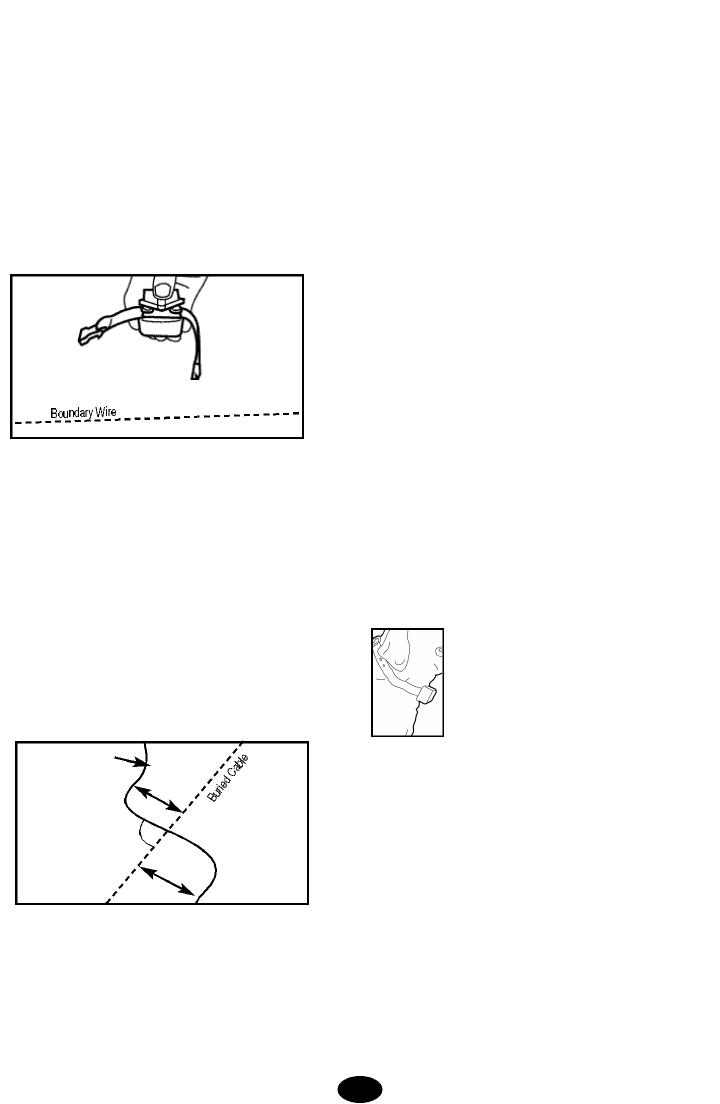
4. Verifying the Safe Part of the Yard
Once the field is set, slowly walk the collar receiver around the
entire boundary perimeter maintaining a distance from the
wire that is at least three feet farther than the field width set-
ting selected in the previous step. Verify the collar receiver
does not activate.Inconsistencies in the field width may occur
where there are buried electrical, telephone, cable TV or other
wires or metallic objects in the yard.The containment signal
from the boundary wire can couple onto the buried wires and
extend the signal into the safe part of the yard.Repositioning
the boundary wire in these areas can minimize the unwanted
signal coupling;however, you may not be able to completely
eliminate the effect. The unwanted signal coupling can be
minimized by orienting the boundary wire so that it is perpen-
dicular to the buried wire for approximately ten feet on each
side of the buried wire (see graphic below).
H.Burying the Boundary Wire
Tools
You may need the following tools for efficient installation:
Straight-edged spade, pliers, and wire cutter/stripper. If you
plan to run the wire across concrete, you will also need a
caulk gun, silicone caulking, and a circular saw with a mason-
ry blade.
1. Ensure the system is turned OFF
Make sure the wall transmitter is turned OFF and the AC
adapter is disconnected from the Lightning Protector.
2. Burying the wire
To bury the wire, dig about 3 to 4 inches deep where the wire
first enters the ground near the transmitter and continue
around the path of the loop wire. A 30˚ to 45˚ angle cut made
with a flat blade spade will be the easiest to close and heal.
Allow for slack in the wire throughout the boundary wire loop
to compensate for expansion and contraction due to temper-
ature changes.
When covering a large area, you may wish to use a lawn
edger or trenching machine to cut into the ground.However,
we recommend that the wire be placed in the trench by hand.
A commercial wire-placement machine may break the wire or
damage the wire insulation.
3. Checking the system field width and placing the flags
Repeat the test from Step G.3 until you are satisfied with the
field width setting.As you approach the boundary wire, place
a flag 3 to 4 feet inside of where the receiver first detects the
warning sound. Continue placing the flags at 6 to 8 foot inter-
vals around the entire containment area using this technique.
If the field adjustment knob position is altered, you must test
the containment field for the desired setting and reposition the
flags as necessary.
4. Plug the holes
With the twisted wire in place near the wall transmitter, caulk
and seal the interior and exterior holes to prevent damage
from moisture and insects.
SECTION 5.
USING THE IF-100 PREMIUM
C O N T AINMENT SYSTEM
A.Fitting the Collar Receiver to Your Dog
1. Probes
Use short probes for shorthaired dogs.Use long
probes for longhaired dogs. Finger tighten the probes,
then turn one additional revolution with the probe
wrench. Do not over-tighten the probes.
2. Collar Strap
The collar receiver should fit snugly at the top of your
dog's neck where the neck is most narrow and has the
least fur. Adjust the collar so it's just snug enough to
slide one finger between the probe and your dog's neck.
To work properly, both probes must contact your dog's
skin. Periodic adjustment of the collar's fit may be nec-
essary as your dog's coat, weight, and age change.
You may think a properly fitted collar receiver is too tight
or too high. Although this is a collar, it is not like any
other, and to work properly it must fit high and snug.
For the safety of your dog, we recommend that you per-
12.
Safe Area
BoundaryWire
10’
10’
90˚
form this check each time you place the collar receiver
on your dog.
B.Setting the Transmitter Controls
1. Correction Level Settings
Always use the lowest correction level necessary to
contain your dog. The goal is for your dog to associate
an unpleasant consequence with ignoring the training
and straying outside the boundary you have defined.
2. Charge Reminder Settings
Your transmitter's built-in charge reminder allows you to
set a timer to remind you that it is time to
check/recharge the receiver battery. The REMINDER
switch allows you to select a reminder interval of 60
(Labeled A) or 30 (Labeled B) days or turn the function
OFF. The timer starts when the collar receiver is
removed from the charger. This switch should be set at
a time interval that will remind you to check the collar
receiver and verify that it has an adequate charge to
contain your dog. During the initial training period or if
your dog frequently "challenges" the containment sys-
tem boundary, we recommend that you set the
reminder switch to the B position and check the collar
receiver indicator light weekly for a low battery indica-
tion.Once your dog is trained or rarely "challenges" the
system boundary, you may be able to set the reminder
switch to the A position and charge the collar receiver
less frequently.
NOTE: The timer is automatically reset when the collar
receiver is placed in the charging cradle for greater than
5 minutes.
3. AlarmVolume Setting
Your transmitter contains an audible alarm to warn you
if there is a break in your boundary wire, a low backup
battery condition, a transmitter power outage or to
remind you to check your receiver battery status. The
volume of the alarm tone can be adjusted using the
ALARM VOLUME knob. Set the alarm volume at a level
that you can easily hear when you are in the vicinity of
the transmitter. To test the alarm volume, disconnect
one of the loop wires at the transmitter.This will cause
the wire break alarm to activate and produce an alarm
tone. Reconnect the loop wire after you have set the
alarm volume.
4. Charging the receiver
Your transmitter includes a built-in battery charger for
the collar receiver. For the transmitter's built-in battery
charger to function, the transmitter must be plugged in,
turned ON and have boundary wire attached to the
LOOP terminals on the transmitter.By placing the
receiver on top of the transmitter in the charge cradle
with the receiver indicator light aligned toward the end
of the charge cradle marked with an arrow a 14-hour
battery charging cycle will be initiated. During this 14-
hour charging cycle, the transmitter indicator light will
flash green and a high frequency tone will be heard
from the transmitter. After the 14-hour charge cycle the
battery charger will continue to provide a trickle charge
to maintain the receiver battery at a full charge.
NOTE: Removing the receiver from the charge cradle
for longer than 15 seconds during the 14-hour charge
cycle (transmitter light flashing green) will result in the
battery charger restarting the 14-hour charge cycle
when the receiver is returned to the charge cradle.
Resetting the 14-hour charge cycle in this manner will
not damage your receiver or transmitter.
To charge additional receivers, wait until the charge
cycle has completed and the indicator light has
returned to a solid green. Wait at least 15 seconds
between removing one receiver and placing the next
receiver on the charge cradle to initiate a new 14-hour
charge cycle for subsequent receivers.
5. Battery Backup
Your transmitter includes the capability to install eight
standard AA alkaline batteries to provide your contain-
ment system with backup power in case household
power fails or the transmitter power adapter is uninten-
tionally disconnected. Your system will function without
the backup batteries installed, but we recommend you
take advantage of this feature for added security and
the safety of your dog.
The condition of the backup batteries is monitored by
circuitry in your transmitter. If the battery voltage drops
below the monitor threshold, an audible alarm sounds
and a yellow light flashes on the transmitter.If you
choose not to maintain backup batteries in the trans-
mitter, you can silence this alarm and turn off the flash-
ing yellow light by setting the BATTERY BACKUP MON-
ITOR switch to the OFF position.
When operating on battery power, the status indicator
light on the transmitter is disabled in order to conserve
battery life. An audible alarm will sound once per sec-
ond to remind you that the system is operating on bat-
13.
collar receiver light to this end

tery power.When the system is using battery power, a
reduction in the containment field width may occur and
is dependent on the length of wire being used and the
containment field width distance setting.For example, a
typical installation using 700 feet of boundary wire with
a normal field width setting of 10 feet will experience
approximately 25% reduction in field width on battery
b a ckup with a fresh set of AA Alkaline batteri e s
installed.This equates to a containment field width of
approximately 7.5 feet.This field width will continue to
reduce over the life of the batteries. After approximate-
ly 20 hours of battery use, the containment field width
will be approximately 6 feet.The batteries will power the
transmitter for approximately 40 hours.At the end of 40
hours of battery use, the containment field width may
be as short as 4.5 feet.The low battery detection mon-
itor built into the transmitter will produce a warning
alarm when the battery life has been reduced by
approximately 50%.
C.Important Notes About the Collar
1. Always use the rubber insulators between the collar
strap and probes to provide insulation in damp condi-
tions.
2. If needed, a small amount of hair removal or thinning
will improve probe contact with the skin.
3. Check your dog's neck at least weekly for skin irrita-
tion.
4.This product is not recommended for dogs under four
months of age.
5. Check the tightness of the probes regularly and fre-
quently to prevent loss of the receiver box . L o s t
receivers are not covered under manufacturer warranty.
6. To prevent accidental correction inside the home,
remove the collar from your dog's neck when it comes
inside.
7. If your dog challenges the system frequently, a full
charge on the receiver will provide approximately 2-4
weeks of use between charges.A full charge will last
over 60 days when the receiver is rarely activated.
8. Check the collar receiver once a week to make sure
the collar receiver has an adequate charge. A green
flashing light once every two seconds indicates that the
collar receiver is adequately charged. A red flashing
light once every two seconds or no flashing light indi-
cates that the collar receiver needs to be recharged.If
the collar receiver will not be used for an extended peri-
od of time (more than 3 months), we recommend you
still charge the collar receiver at least once every 3
months to maximize battery life.
9.Test the collar receiver in the containment field week-
ly to verify that the system is functioning properly. To
test, hold the supplied test light to the collar receiver
probes. Holding the receiver by the case, NOT by the
probes, walk into the containment field.With the receiv-
er held at the height of your dog’s neck with the probes
facing upward, verify the warning sound is present and
the test light illuminates.
SECTION 6.
TIPS FOR CONTAINMENT TRAINING
To get the most out of your containment system, keep
these tips in mind:
1.The collar receiver must be properly fit to ensure ade-
quate contact between your dog's skin and the receiver
probes. Place the collar high and snug on your dog's
neck.
2 . A l ways use the lowest correction level on the
adjustable wall transmitter necessary to contain your
dog. Proceed to higher correction levels only if necessary.
3. Never leave the collar receiver on your dog for longer
than 12 hours a day. Leaving the collar on your dog for
extended periods could result in irritation around the
neck or at the site where the probes make contact with
the skin.Check your dog’s neck weekly for signs of skin
irritation.
4. Begin training when your dog has reached at least
four months of age.
5. Always make sure the collar is functioning properly
BEFORE putting it on your dog. Verify the containment
transmitter is operating properly and the field width is
appropriate. To test the containment field, refer to
Section 4.G.3.pg 11 Field Width Testing the System.
6. If a metal slip collar is used for training it must be
properly positioned low on your dog's neck when he
wears the Invisible Fence®collar receiver. Slip collars
are not safe for casual wear and must be removed after
each lesson. Metal tags on collars must be positioned
to prevent any contact with the containment receiver
probes. Any metal contacting the probes may prevent
the correction from affecting your dog.
7. Place the training flags 3 to 4 feet inside the perime-
ter of where the warning sound is heard. This will add
a visual cue to the audio warning sound and help your
dog learn the boundary.
8. Never call or pull a dog into the containment field.
9. Keep training sessions brief (10 to 15 minutes) and
stop the session before your dog has lost interest. End
the session with play.
10. Do NOT become overly confident that your dog has
become conditioned sooner than expected. Complete
all of the steps in the Training Plan before allowing your
dog to run free.
11. ALWAYS praise your dog for appropriate behavior.
14.
neck and snug with the probes touching the skin.
Start every session with play and praise.Make sure the
dog is comfortable--have fun! Laugh! and praise him.
Most importantly, review the previous day's lesson to
see if your dog is learning on schedule.Do not proceed
to the next step until your dog understands what is
expected.Do boundary work at locations all around the
property.End the session with relaxing play.
Bring your dog indoors and remove both the training
collar and the collar receiver.If you're training more than
one dog, train each dog at separate training sessions.
D.Training Lessons
Lesson 1:
Before you start to train - Make sure the collar receiver
is fully charged. Remove the standard probes and
install the training probes.The training probes are the
black plastic probes.The training probes ensure that
your dog does not receive a correction until he learns to
retreat from the boundary.
Put the collar receiver on your dog.Make sure the wall
transmitter is turned on.
Lesson 1- Day 1.The goal for day 1 is to introduce your
dog to the boundary and to help him understand he
should retreat when he hears the warning sound.
Depending on the lead there are several ways to do
this.
Using a 6-foot lead, casually walk your dog to the
boundary.When the dog reaches the containment field
let go of the slack in your left hand, immediately spin to
your right, and instantly grasp the lead under your right
hand and retreat. Your dog will continue forward and
then feel the tug. As he runs back towards you, praise
him.
Using a retractable or 15-foot lead, casually walk your
SECTION 7.
THE TRAINING PLAN
The goal of Invisible Fence®training is:
• To teach your dog to identify and retreat from the
boundaries.
•To make the training fair--so your dog will understand
the consequences of leaving the yard.
• To make the training fun--so your dog will enjoy stay-
ing and playing on your property.
This training plan is divided into four parts: training
equipment, the schedule, rules and routine, and training
lessons.
A.Training Equipment
You'll need a training collar.Choose either a flat or slip
collar. Use a flat collar on a mild mannered dog.A slip
collar works best on a hard to handle or easily distract-
ed dogs.
You'll need a lead.Invisible Fence training allows you to
work with a 6-foot, 15-foot, or retractable lead.
B.The Schedule
The six Invisible Fence dog-training lessons take place
over the course of about 4 weeks. For total success it is
necessary to complete the entire course.
Practice sessions are 10-15 minutes each, 2 times per
day. Short, fun sessions are more effective. Anything
longer will cause your dog to mentally tire.
Lesson 1: The retreat pattern - 6 Sessions.
Lesson 2: The correction - 1 Session.
Lesson 3: Distractions - 7-8 Sessions.
Lesson 4: Off Lead Supervised - 1 Week
Lesson 5: Off lead Unsupervised - 2 Weeks
Lesson 6: Flag Removal - Every other day until gone.
Use the calendar only as a guideline.Your dog's behav-
ior tells you when to move to the next lesson.
C.Rules and Routine
The rules and routine of the typical training session
include putting the collar receiver and lead on your dog
making sure the collar receiver is high on your dog's 15.
MTWT F S S
Week 1 Retreat Distractions
Week 2 Off Lead Supervised
Week 3 Off Lead Unsupervised
Every
Other Flag Removal
Day
Proper Fit:
The collar receiver should
fit snugly at the top of your dog's neck .
Adjust the collar so it's just snu g
enough to slide one finger betwe e n
the probe and your dog's neck .

dog toward the boundary. Your dog may indicate he
hears the warning sound by tilting his head or twitching
his ears.The instant the dog hears the warning sound,
give a tug on the lead and bring him back.
On a retractable lead, press the brake.This will redirect
the dog back into the safe area. Have fun and praise
him.
On days two and three repeat the lesson of day one.
As the training sessions progress through the three
days of lesson one, you'll see that your dog will begin to
anticipate the signal and retreat without prompts.
Day three is successful if your dog retreats with no
prompt from you or he refuses to approach the bound-
a ri e s. Remember to pra i s e, pra i s e, praise proper
behavior.
Lesson 2: - The Correction:
A dog may be tempted to break the rules. To prevent
this, he must understand that there are consequences
for inappropriate behavior.When your dog retreats from
the boundaries on his own, or won’t go into flagged
areas, he is ready to receive the correction.
Before you begin this lesson remove the training probes
and install the standard probes.Make sure the wall
transmitter is turned ON and functioning properly.
Use a 15-foot or a retractable lead.Have a family mem-
ber run through the containment field.Let your dog fol-
low. The distracter must not stop, look back, or call the
dog. After your dog receives the correction, pull him
back to you and lavish him with loud, happy praise.Try
it again.If he responds correctly, praise him, then move
to another boundary area.
Lesson 3 - Distractions:
If your dog is avoiding the boundary, he is ready for dis-
tractions. This is the most important but often short-
changed part of the training.This lesson teaches your
dog that he must resist temptations. When practicing
distractions, never call or pull your dog into the contain-
ment field.
Most dogs have a hard time generalizing concepts so
you can't assume that if your dog won't chase a ball he
won't chase a bicycle.You have to go through a list of
distractions that will tempt your dog the most.Dogs will
learn specifics. If your dog likes to chase, distract with
balls, bikes--anything that moves.If your dog is attract-
ed by children, family members, other dogs--use them
as temptations.
Lesson 4 - Off Lead Supervision:
After several sessions of distractions, your dog should
be ready for off lead play.You must stay in the yard for
off lead training.
In fact, it's wise to spend more quality time in the yard
with your dog.The more your dog stays on the proper-
ty for the first month, the less confused he will be.
If you wish to take your dog off the property, remove the
collar receiver and take him off and back onto the prop-
erty in the car.
Lesson 5 - Off Lead Unsupervised:
When your dog resists distraction of any kind, both on
and off lead, he can be left unattended in the yard but
observed from inside the home.This freedom should be
brief at first.You must frequently go out and check on
your dog. Over the next several weeks, unsupervised
freedom can be gradually increased.
Before and after each unsupervised session, you must
continue the play and praise routine so that your dog
understands that the yard is a happy place to be.
Lesson 6 - Removing the Flags:
After 2 weeks of successful unsupervised containment,
you can begin removing the flags.Start by removing
every other flag every other day until all are gone.
The leads, trainers, flags and the collar receiver signals
are all training clues for your dog.During the last three
weeks of training --one by one--all but the collar receiv-
er will be removed.
As the training clues are removed it is essential that you
continue to use distractions to make sure your dog
retreats from the unmarked boundary.
The correction teaches the consequences of the
improper response.Know your dog and what tempts
him.Gradually extend the amount of unsupervised free-
dom, and finally remove the flags when you are confi-
dent that your dog is fully trained.
If you have any questions about your containment sys-
tem, or about training your dog, please review the video
included with this product.If you still have questions or
concerns, please call us at 800-688-4364.
SECTION 8.
T R O U B L E S H O O T I N G
The fo l l owing table identifies the solutions to common prob-
lems associated with pet containment systems. If a prob-
lem occurs, first check this table and try to determine what
the problem may be.I f, for any reason, your Inv i s i ble Fe n c e
system still does not operate as described in this manual or
if you have any questions or problems not included in this
m a nual, please call Inv i s i ble Fence at 1-800-688-4364.
16.

Dog Response
Problems:
1. Dog appears to not "feel"
the correction.
2.Dog appears to "feel" the
correction but still constantly
enters or stands in the con-
tainment field.
-or-
Dog "feels" the correction, but
attempts to run through the
containment field often.
3.Dog receives an intermittent
signal.
4.Dog acts fearful of going
into the yard.
5.Dog receives corrections in
the safe part of the yard.
Possible Solutions:
1.Collar fit is not tight enough to make good skin contact.See Section
5.A page 12.
2.Collar probes not long enough to make good skin contact.Use long
probes supplied with system.
3.Dog’s hair too long or thick.Trim the hair in the appropriate area or
call Invisible Fence®at 1-800-688-4364 for special thick hair probes.
4.Receiver battery not charged.If the receiver LED is flashing red or
there is no light, recharge battery. See Section 5.B.4, page 13.
5.Correction level too low. Set the Correction level switch to the next
higher level.
6.Collar receiver may have loosened over time and may not be tight
enough to make good skin contact.See Section 5.A page 12.
7.Ve rify that the transmitter power is turned on and functioning properl y.
8.Remove any metal collars from the dog.
9.Make sure any metal tags cannot contact the collar probes.
1.Collar fit is not tight enough to make good skin contact. See Section
5.A page 12.
2.Correction level too low. Set the Correction level switch to the next
higher level.
3.Field width setting is not wide enough.Increase the containment field
width and re-verify the detection distance.See Section 4.G.page 11.
4.Remove any metal collars from the dog.
5.Make sure any metal tags cannot contact the collar probes.
6.Additional training is needed in the presence of outside distractions.
See Section 7 page 15.
1.Use of non-waterproof connections in containment installation. See
Section 4.F.3 Splices, page 10.
2.A nick or scrape in wire insulation. Perform the Wire Break Location
Test Procedure. See Section 8.B.pg 19.
1.Correction level too high.Set the Correction level switch to the next
lower level. See Section 5.B.1.page 13.
2.Dog has received a correction too soon during the training.Stop
training and play with dog in the safe area.Resume training when dog
is no longer fearful in the safe area.
3.Field width set too high.Re-verify the detection distance and adjust
field width if necessary. See Section 4.G.page 11.
4.Check yard’s safe area for unexpected containment signal due to sig-
nal coupling.See Section 4.G.4.pg 12.
1.Field width set too wide.Decrease the containment field width and
re-verify the detection distance. Change field size switch to SM if nec-
essary. See Section 4.G.page 11.
2.Check for buried cables, wires, or metallic objects in the yard.See
17.

18.
6.Dog receives correction inside
the home
Transmitter Problems:
1. Transmitter alarm is operating
and status light is flashing.
2.Transmitter status light indicates
the boundary wire is broken or
disconnected.
3.No status light on the transmit-
ter and alarm is silent.
4.No status light on the transmit-
ter and the alarm is on.(System
on battery backup power.)
Section 4.G.4.page 12.
3.Reposition boundary wire away from fixed metal objects such as
metal buildings, chain-link fences, large satellite dishes, etc.
4.Move large metal objects such as swing sets and trampolines
farther away from the boundary wire.
1.Remove the collar receiver when the dog enters the home.
2.Field width too wide.
3.Reposition the boundary wire farther from the house. See
Section 4.A page 7.
4.Place transmitter and lightning protector away from areas where
the dog may be confined.A low level containment signal is radiated
from these components and can cause the collar receiver to func-
tion.Verify that the containment wire remains tightly twisted at each
component connection point.
Possible Solutions:
Check the status indication table located on transmitter and in
Section 1 page 5 to determine cause and corrective action.
1.Check boundary wire connections at transmitter and lightning
protection module for proper connection.
2.Check for broken or damaged wires at outside entry into house.
3. Perform Transmitter Loop Test Procedure to locate and correct
the problem. Section 8.A.pg 19.
4.PerformWire Break Location Test Procedure and correct the
problem.Section 8.B.pg 19.
1.Verify the transmitter POWER switch is ON.
2.Check that the adapter and lightning protector are plugged in
properly.
3.If system is plugged into a GFCI outlet, check to see if the circuit
has been tripped.Reset GFCI circuit if required.
4.If the green power light on the lightning protector is not illuminat-
ed, verify that the outlet is working properly by plugging in a known
working item such as a radio.
5.Unplug the lightning protector and plug the power adapter direct-
ly into the 110-volt outlet.If the transmitter operates when bypass-
ing the lightning protector, contact Invisible Fence for a warranty
replacement lightning protector. Do not use the system until a
replacement lightning protector has been provided.
6.If possible, check the voltage of the power adapter using a digital
multimeter. It should read greater than 24 volts AC.
1.Check that the adapter and lightning protector are plugged in
properly.
2.If system is plugged into a GFCI outlet, check to see if the circuit
has been tripped.Reset GFCI circuit if required.
Dog Response Problems: Possible Solutions:

Always remove your dog’s collar receiver before per-
forming any transmitter testing.
A.Transmitter Loop Test Procedure
The transmitter loop test procedure is use to determine
the cause of a "Boundary Wire Broken or
Disconnected" alarm indication.You will need a short 6-
5. Transmitter status/alarm priori-
ty sequence.
Collar Receiver Problems:
1.Collar Receiver does not
appear to be operating in con-
tainment field area.
2.Collar Receiver is not taking a
charge.
3. Receiver is not working and
case is damaged or "chewed" by
dog.
3.If the green power light on the lightning protector is not illuminat-
ed, verify that the outlet is working properly by plugging in a
known working item such as a radio.
4.Unplug the lightning protector and plug the power adapter
directly into the 110-volt outlet.If the transmitter operates when
bypassing the lightning protector, contact Invisible Fence for a war-
ranty replacement lightning protector. Do not use the system until
a replacement lightning protector has been provided.
5.If possible, check the voltage of the power adapter using a digi-
tal multimeter. It should read greater than 24 volts AC.
Under multiple operating/fault status conditions, the operating/fault
alarm priority sequence is as follows:
1.Boundary wire broken or disconnected.
2.AC power disconnected operating on battery backup power.
3.Receiver charging.
4.Receiver charge reminder.
5.Backup batteries low.
Possible Solutions:
1.Verify the transmitter is turned on and the status light is solid
green.
2.Check the collar receiver for a green flashing indicator light.If
light is flashing red or there is no light, recharge battery. See
Section 5.B.4, page 13.
3.Perform the field width test of Section 4.G.3 page 11 using the
test light and determine if the test light is illuminating.
4.Perform System Test procedure to determine which component
is malfunctioning.Section 8.C. pg 20.
1.Check that the collar is proper positioned in the charging cradle
on top of the transmitter.When properly positioned the transmitter
status light will flash green and a high frequency charge tone will
be heard.
2.Check that the adapter and lightning protector are plugged in
and either the boundary loop wire or a short test loop wire is con-
nected.A loop wire must be connected for the charger to function.
Contact Invisible Fence®at 1-800-688-4364 to purchase a new
collar receiver.
Transmitter Problems: Possible Solutions:
foot piece of green boundary wire with 3/8-inch of the
insulation stripped from both ends.Verify the transmitter
is plugged into lightning protector, the tra n s m i t t e r
POWER switch is ON, and all boundary wire connec-
tions at the lightning protector and transmitter are prop-
erly connected.If the status light is still flashing red and
the alarm is on, continue with the following steps.
19.
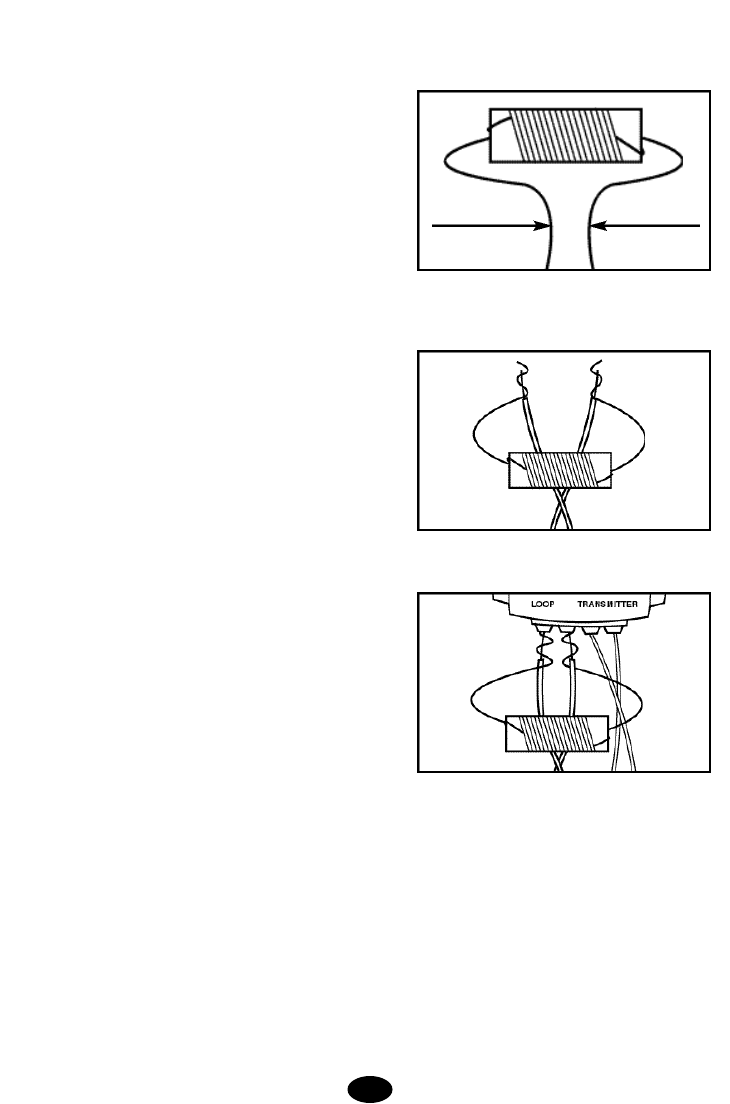
1. Remove the existing pre-twisted wire pair from the
lightning protector LOOP connector by pressing the red
release levers on the connector and pulling the wires
free from the unit.
2. Insert both ends of the 6-foot wire into the LOOP
connector on the lightning protector and recheck the
transmitter status light and alarm.
a. If the status light is green and the alarm is off, the
problem is in the boundary wire.Check for visible
damage to the wire at the entry into the house.If none
is observed, perform the Wire Break Location Test
Procedure to find and correct the wire break (Sec.B).
b. If the status light is still flashing red and the alarm
is on, remove the 6-inch wire, reconnect the bound-
ary wire to the lightning protector and continue with
the following steps.
3. Remove the existing pre-twisted wire pair from the
transmitter LOOP connector by pushing the orange
release levers on the connector away from the wires
and remove the two wires from the transmitter.
4. Insert both ends of the 6-foot wire into the LOOP
connector on the transmitter and recheck the transmit-
ter status light and alarm.
a. If the status light is green and the alarm is off, the
problem is in the lightning protector.The lightning pro-
tector has a lifetime warranty.Contact Invisible Fence
at 1-800-688-4364 for a warranty replacement.
b. If the status light is still flashing red and the alarm
is on, the malfunction is in the transmitter. Contact
Invisible Fence at 1-800-688-4364 for assistance.
B.Wire Break Location Test Procedure
The wire break location test procedure is used to locate
broken or damaged sections of the containment bound-
ary wire. To locate wire breaks in the loop installation,
you will need a portable AM radio and a RF Choke
(available at Radio Shack®;part number 273-102).
Once you have these items, follow these steps:
1. Disconnect the transmitter power by unplugging the
power adapter from the outlet.
2. Disconnect the boundary wires from the Lightning
Protector LOOP terminals.(If you have a digital multi-
meter available, confirm the existence of a complete
wire break by measuring the continuity between the two
wires.If the wire is intact the total resistance measured
for 18 AWG wire should be 0.00639 Ohms per foot mul-
tiplied by the total length of the wire in feet that you
installed in your system, i.e. 0.00639 Ω/ft x 700 feet =
4.473 ohms.NOTE: Measuring the continuity will not
detect the presence of nicks or scrapes in the wire insu-
lation.) The following tests must be performed to locate
these damaged sections.
3. Bend the leads of the RF Choke into the shape
shown in figure.
4. Carefully wrap the RF Choke leads around the
boundary wire leads as shown.
5.Plug the RF Choke and boundary wire leads into the
loop terminals on the lightning protector as shown.
6. Plug the power adapter back into the Lightning
Protector outlet.
7. Set the portable AM radio to AM-60 or AM-600
(whichever one has no station).
8. Adjust the transmitter FIELD WIDTH knob high
enough to obtain a signal on the portable radio when
holding the radio over the containment boundary wire.
The signal that you receive is short static pulses.
9.The signal should be absent on the twisted wire por-
tions because twisting cancels the signal.
10. Hold the radio 1 to 2 feet off the ground and swing
the radio (side to side, left to right) over the wire as you
walk along the boundary.
20.
1/4”
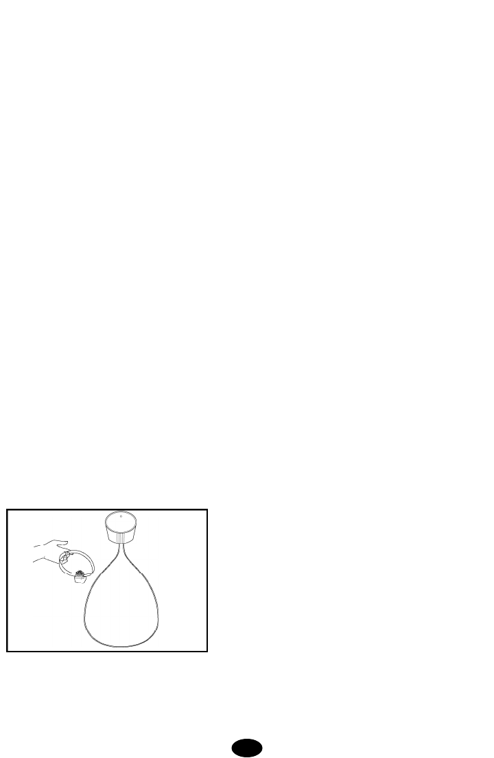
11. If the pulsating static stops, weakens, or changes
pitch, mark the spot with a flag or stick. No sound indi-
cates a complete break in the wire. If the signal fades
or changes in pitch, look for a nick in the wire insulation.
Note: Do not confuse straying from the boundary wire
path for a wire break. Make sure you follow the known
location of your boundary wire.
12.Continue around the remaining boundary and mark
any additional signal change with a flag or stick.
13. After completing the entire boundary, return to the
marked spots. Examine the wire for 3 to 4 feet in each
direction.
14. Replace the wire using the same gauge wire used
in the original installation and use waterproof splices to
make the connections.Contact Invisible Fence for addi-
tional wire and waterproof splices if needed.
C.System Test Procedure:
The system test procedure is used to determine the
probable cause of system problems that have not been
addressed elsewhere. You will need a 10 foot piece of
green boundary wire for use as a test loop wire. Strip
3/8-inch of the insulation from both ends of the wire.To
perform the System Test Procedure, please follow these
steps:
1. Remove the collar receiver from your dog prior to
performing the following tests.
2. Slide the transmitter POWER switch to the OFF posi-
tion.
3. Set the FIELD SIZE switch to SM.
4. Disconnect the existing pre-twisted pair boundary
wire from the LOOP connector on the transmitter.
5. Insert the two ends of the test loop wire into the
LOOP connector on the transmitter.
6. Note the original position of the FIELD WIDTH
Adjustment Knob and turn the FIELD W I D T H
Adjustment Knob to the minimum setting (MIN).
7. Slide the transmitter POWER switch to the ON posi-
tion.
21.
8. Place the test light on the collar receiver. With the
collar strap in hand, back up to be outside the field and
approach the test loop. Make a mental note of the dis-
tance between you and the wire when the collar acti-
vates.
9.Turn the FIELD WIDTH adjustment knob to 10 o'clock
or a medium setting.
10. Back away from the wire and approach it again.
Determine the distance between you and the wire when
the collar activates. The distance should be greater on
the 10 o'clock range setting than on the minimum set-
ting.
11. If more than one collar receiver is used on the sys-
tem, repeat the above test on each collar.
12. Interpreting the Results
a. If there is no light on the transmitter or a red flash-
ing light with an alarm, the transmitter is malfunction-
ing.
b. If the green light is solid on the transmitter but the
collar does not activate on the test loop wire, the col-
lar receiver is not working.
c. If the green light is solid on the transmitter and the
collar receiver is activating at different distances on
the test loop wire, the problem is in either the yard
wire or the Lightning Protector. Reconnect the trans-
mitter to the Lightning Protector and connect the test
loop to the Lightning Protector LOOP terminals.
Repeat test Steps 6 through 11. If the green light is
solid on the transmitter and the collar receiver is acti-
vating at different distances on the test loop wire, the
problem is the boundary wire.Perform the Wire Break
Location Test Procedure.If there is a red flashing light
with an alarm on the tra n s m i t t e r, the Lightning
Protector is malfunctioning. The Lightning Protector
has a lifetime warranty. Contact Invisible Fence®at 1-
800-688-4364 for a warranty replacement lightning
protector.
13. When testing is complete return the FIELD SIZE
switch to its original position (SM for 1000 feet or less of
boundary wire and LG for over 1000 feet). Turn the
FIELD WIDTH Adjustment Knob to its original setting.
14. Repeat the field width testing from Step G.3 page
11, until you are satisfied that the field width setting has
been returned to your desired detection distance.
SECTION 9.
GENERAL MAINTENANCE TIPS
Your system requires very little maintenance. The wall
transmitter is not waterproof and must be protected
from the weather. It should never be immersed in any
liquid. To clean the transmitter, unplug the AC adapter.

Do not use liquid or aerosol cleaners. Use a soft cloth,
slightly dampened with water if necessary, to clean your
transmitter.
The collar receiver is waterproof and will continue to
function after being submerged in water. To remove
dirt, simply wipe with soap and water. Never place the
collar in a dishwasher.
Do not attempt to dismantle or repair any of the system
components;this will void the manufacturer's warranty
in full. These components contain computerized cir-
cuitry that should be serviced only by a factory author-
ized expert.
EXTRA RECEIVER COLLARS
Any number of collar receivers may be added to this
containment system. For extra collars call Invisible
Fence 1-800-688-4364.
IF YOU HAVE ANY QUESTIONS ABOUT THE
USE OF YOUR CONTAINMENT SYSTEM, DO
NOT RETURN IT TO THE PLACE OF PUR-
CHASE. CALL INVISIBLE FENCE AT
1-800-688-4364 (US).
SPRING/SUMMER HOURS: MONDAY
THROUGH FRIDAY 8 AM TO 5 PM,
CENTRAL TIME
S AT U R D AYS 8 AM TO 4 PM
FALL/WINTER HOURS: MONDAY THROUGH
F R I D AY 8 AM TO 5 PM, EASTERN TIME
S AT U R D AYS 8 AM TO 4 PM
LIMITED LIFETIME WARRANTY
Invisible Fence®, Inc. warrants that its IF-100 pet con-
tainment system ("System") will be free from defects in
material and workmanship, under normal use, for a
period of one year from the date of the original retail
purchase. If you are not satisfied with the performance
of this product, please call 800-688-4364 for return
instructions. Please do not return the product to your
retailer. After one year from date of original consumer
purchase, a prorated parts and labor schedule provides
additional warranty coverage.Please call 800-688-4364
for details.
The IF-100 Pet Containment System is also covered by
the Invisible Fence 30-day money-back guarantee. If
you are not satisfied with the performance of this
System, please call 1-800-688-4364, to obtain instruc-
tions on how to return your System and receive a
refund.
During the 12-month period, Invisible Fence will either
repair, or replace any defective components, subject to
a $15.00 processing fee. Prior to returning any compo-
nent to Invisible Fence, the purchaser is urged to call 1-
800-688-4364 to obtain instructions on returning com-
ponents.
This Limited Warranty extends to and is enforceable
only by the original retail purchaser during the period
such original purchaser resides at and owns and occu-
pies without interruption the real estate upon which the
System is installed. This Limited Warranty covers only
the components manufactured by Invisible Fence, Inc.
Invisible Fence, Inc.neither assumes, nor do we author-
ize any other person to assume for us, any other liabili-
ty in connection with the sale of products of Invisible
Fence, Inc. The Limited Warranty of Invisible Fence,
Inc.shall not apply to any product that has been subject
to accident, neglect, alteration, or misuse. This Limited
Warranty is void if any attempts are made to alter or
repair any component prior to returning it to our facility.
This Limited Warranty specifically excludes lost parts or
components, broken probe studs, damage as a result of
dog chews, or lightening damage caused by improper
installation of the supplied Lightning Protector.
The Lightning Protector is warranted to be free from
defects in design, material and workmanship under the
same terms and conditions as provided in this Limited
Warranty pertaining to other components within the
system. In addition, Invisible Fence will replace any
defective Lightning Protector component and/or repair
any Lightning Protector component that has suffered
damage as a result of a lightening surge or line over-
vo l t a g e. The Lightning Protector is specifically
designed for electronic dog containment systems and
will not protect other types of electrical equipment or AC
surges.
THE REMEDIES AS SET FORTH IN THIS LIMITED
WARRANTY SHALL BE THE EXCLUSIVE REMEDIES
AVAILABLE TO THE ORIGINAL RETAIL PURCHAS-
ER, AND INVISIBLE FENCE, INC.SHALL NOT BE
LIABLE OR RESPONSIBLE FOR ANY INCIDENTAL
OR CONSEQUENTIAL DA M AGES RESULT I N G
FROM THE USE OF THE PRODUCT COVERED BY
THIS LIMITED WARRANTY OR CAUSED BY ANY
DEFECT, FAILURE OR MALFUNCTION OF THE SYS-
TEM, WHETHER A CLAIM IS BASED UPON WAR-
R A N T Y, CONTRAC T, NEGLIGENCE OR OT H E R-
WISE. Some states do not allow the exclusion of inci-
dental or consequential damages, so this limitation may
22.

not apply in your particular state. This limited warranty
gives you specific legal rights, and you may have other
rights which vary from state to state.
To the extent permitted by applicable law, THIS LIMIT-
ED WARRANTY SPECIFICALLY EXCLUDES ANY
AND ALL IMPLIED WARRANTIES OF MER-
CHANTABILITY AND/OR FITNESS FOR A PARTICU-
LAR PURPOSE. Otherwise all implied warranties are
limited in duration to one year from the date of original
retail purchase. THERE ARE NO OTHER WA R-
RANTIES, EITHER EXPRESS OR IMPLIED, OF ANY
KIND OR NATURE WHICH EXTEND BEYOND THE
DESCRIPTION ON THE FACE HEREOF.
This System is not a substitute for traditional obedience
training. Invisible Fence does not warrant the effective-
ness of this product due to variances in canine person-
ality, temperament and influences beyond the control of
Invisible Fence.
If a warranty claim is to be made, please call 1-800-688-
4364 to obtain a Return Materials Au t h o ri z a t i o n
Number (RMA) and instructions on how to return the
p r o d u c t . D e fe c t i ve components or the complete
System should be sent by insured U.S. mail, or UPS to
the address specified below. All returns are subject to
a $15.00 processing fee and such processing fee must
be included with the returned product.
INVISIBLE FENCE INSTALL-IT-YOURSELF
1000 FULLER DRIVE
GARRETT, IN 46738
IMPORTANT WARNINGS
WARNING 1:
Occasionally an animal cannot be trained to avoid
crossing the containment boundary. Sometimes even a
p r o p e rly trained animal may cross the boundary.
Therefore, Invisible Fence Inc.and its Distributors can-
not guarantee that the system will, in all cases, keep the
Customer's animal within the established boundary.
Accordingly, if the Customer has reason to believe that
his or her animal may pose a danger to others or harm
itself if it is not kept from crossing the boundaries, the
customer should not rely solely upon the system to
keep the animal from crossing the boundary. US Patent No.6,184,790
Invisible Fence is a registered trademark of Invisible Fence, Inc.
All other product or service names are the property
of their respective owners.
© 2002, Invisible Fence. All rights reserved. 2100202
23.
IMPORTANT NOTICE:This equipment has been tested and found to comply with
the limits for a Class B digital device, pursuant to Part 15 of the FCC Rules. These
limits are designed to provide reasonable protection against harmful interference in
a residential installation.This equipment generates, uses and can radiate radio fre-
quency energy and, if not installed and used in accordance with the instructions,
may cause harmful interference to radio communications. However, there is no
guarantee that interference will not occur in a particular installation. If this equip-
ment does cause harmful interference to radio or television reception, which can
be determined by turning the equipment off and on, the user is encouraged to try
to correct the interference by one or more of the following measures:
• Reorient or relocate the receiving antenna.
• Increase the separation between the equipment and receiver.
• Connect the equipment into an outlet on a circuit different from that to which the
receiver is connected.
• Consult the dealer or an experienced radio/TV technician for help.
Caution: Changes or modifications to any component, not expressly approved by
Invisible Fence, Inc., could void the user's authority to operate this equipment.
The term "IC:" before the radio certification number only signifies that Industry of
Canada technical specifications were met.
WARNING 2:
The control panel of the wall transmitter includes visual and
audio signals to warn of a system malfunction, and is there-
fore intended to be installed in a place where such signals
may be easily seen and heard. If the control panel is installed
in an enclosed box or in a place not readily accessible to the
Customer, the Customer will forfeit the benefits of the sys-
tem's warning functions for which Invisible Fence Inc.and its
distributors assume no responsibility.
WARNING 3:
The user of this system is hereby warned to be alert for growl-
ing, snarling, biting, or other aggressive behavior by an animal
using the system, especially during training. If any such
behavior is observed, particularly if it appears to be associat-
ed in any way with the system, the Customer should immedi-
ately stop using the system, unplug the transmitter, and con-
tact Invisible Fence at 1-800-688-4364.
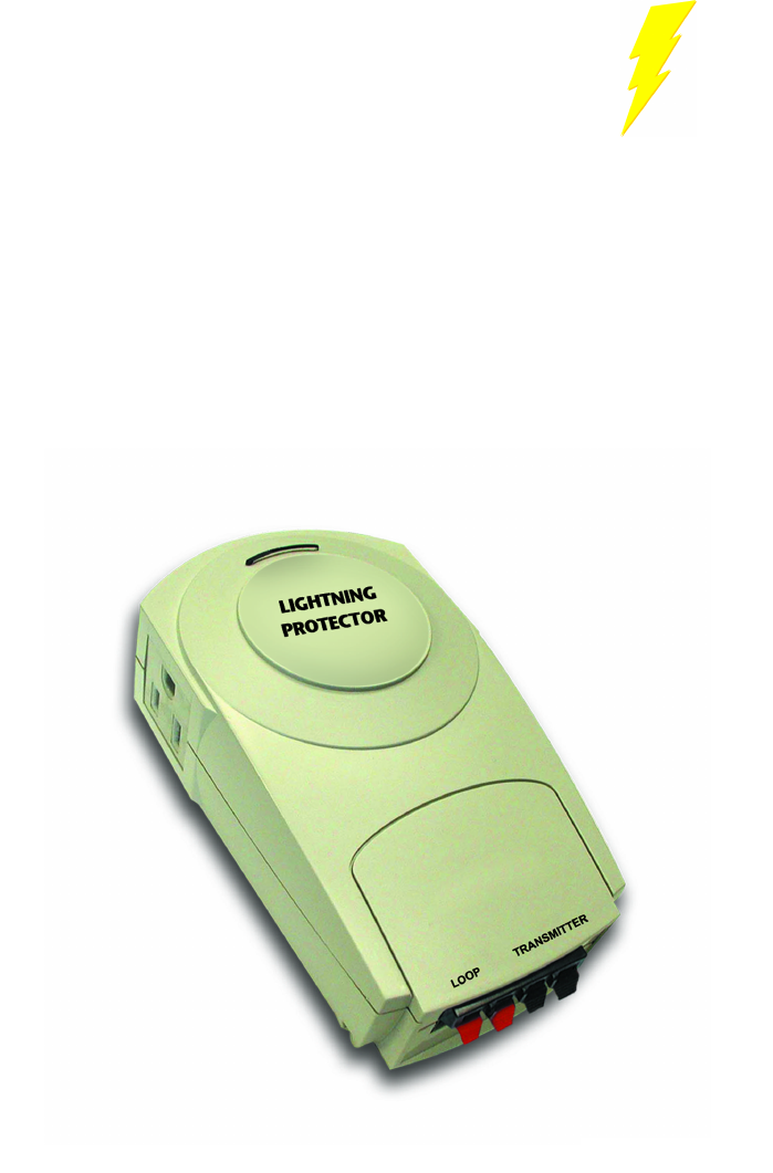
Lightning
Protector
Instructions
The Lightning Protector is designed to protect electronic pet containment
system wall-mounted transmitters against damage from lightning.
Lightning Protector contains two protectors.One stops lightning currents
from entering through the loop wire;the other stops lightning from enter-
ing through the AC power connection.
2100156

Lightning
Protector
Instructions
INSTALLATION INSTRUCTIONS
The Lightning Protector takes only minutes to install:
1.Turn off your containment system.If your pet is in the containment area, make
sure that it is otherwise contained, or bring it inside.
2. Do not begin installation if there is visible lightning in the area or if you hear
thunder.
3. Plug the Lightning Protector into a grounded (3-prong) household outlet (120V
AC) within five feet (5') of where you want to position the transmitter.The green
power light should illuminate, indicating the Lightning Protector is powered.If the
green light does not illuminate, recheck all connections.
NOTE: Avoid using an AC outlet protected with a ground fault current interrupter
(GFCI).The containment system and the Lightning Protector will function properly
in a GFCI outlet, but in rare cases lightning strikes may cause the GFCI to trip,
and you will have to reset it in order for your containment system to function prop-
erly.
4. Cut the in-ground loop wires near the Lightning Protector and strip 1/4" insula-
tion from their ends.
5. Insert the stripped ends of the in-ground loop wire into the left two red connec-
tor holes on the bottom of the Lightning Protector.Use your finger to depress the
tab, then insert the wire and release the tab (see diagram).
Insert the ends of the two transmitter wires into the right two black connector
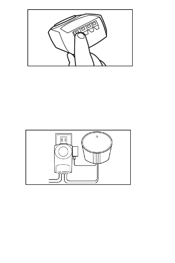
holes on the bottom of the Lightning Protector.
WARNING: Verify the loop and transmitter wires are connected to the proper
Lightning Protector terminals. Damage to the Lightning Protector and transmitter
can occur if connections are reversed.
6. Plug the transmitter power AC adapter into an AC outlet on the side of the
Lightning Protector (see diagram).The AC adapter cord may be secured to the
bottom of the Lightning Protector using the included wire tie.Turn on the contain-
ment system.
If you have added the Lightning Protector to an existing containment system,
check the signal field for width and continuity.Adjust as necessary. If the
Lightning Protector is being installed with a new system, follow the signal field
adjustment procedures given in the containment system's owner's guide.

INVISIBLE FENCE®STANDARD LIFETIME WARRANTY
Invisible Fence warrants to the purchaser of this Lightning Protector, for his or her
life, that this Lightning Protector shall be free of defects in design, material, or
workmanship and that Invisible Fence will replace any defective unit and repair
any unit that has suffered damage from a lightning surge or line overvoltage.
Note that this Lightning Protector is specifically designed for electronic dog con-
tainment systems and will not protect other kinds of equipment against lightning
or AC surges.There is no warranty for any equipment connected to this Lightning
Protector.