Radio Systems 050808 Safe Dog Monitor/ Dialer Transceiver System User Manual KZ3 050808 manual
Radio Systems Corporation Safe Dog Monitor/ Dialer Transceiver System KZ3 050808 manual
UserManual.wiki
>
Radio Systems
>
050808 User Manual
Users Manual
Navigation menu
Upload a User Manual
Namespaces
Wiki Guide
HTML
PDF
Info
Views
User Manual
Discussion / Help
Navigation
![- DRAFT - Rev. 1.0 JAB 4 G:\PCTEST LAB\2006 Reports\TRP\Safe Dog Monitor - Part 68\TCB Documents\KZ3-050808 manual.doc Need Part Number 1.0 Product Introduction This document contains important information regarding the installation and operation of the Invisible Fence® Brand Safe Dog® Monitor. Prior installation of both the signal field wire and Invisible Fence Brand transmitter is assumed. Review all instructions before installation and use. 1.1 Safe Dog Monitor System Overview The Safe Dog Monitor is designed to continuously monitor the signal transmission of an Invisible Fence Brand transmitter and detect when a change occurs in signal amplitude – specifically, the detection of a wire break condition. The Safe Dog Monitor will also detect an increase or decrease in the signal amplitude and an RF Link Communication failure between the Loop Sensor and Dialer Unit. The Safe Dog Monitor is capable of monitoring the signal of the following Invisible Fence Brand transmitters: r ICT 700 Series Transmitters (700, 725, 750, 775) r ICT 800 Series Transmitters (801, 802, 810) r Invisible Gate® r Invisible Mask® II Before the Safe Dog Monitor is installed, the Invisible Fence Brand pet containment system should be completely installed and operational. 1.2 Important Precautions and Warnings Caution: Never install or service any Invisible Fence Brand equipment during a thunderstorm or electrical storm, or when thunder or lightning are in your area. 1.3 Required System Components for Installation The following system components are required for installation of the Safe Dog Monitor. 1. Safe Dog Monitor Loop Sensor [Picture of Loop Sensor] 2. Safe Dog Monitor Dialer Unit [Picture of Dialer Unit] 3. Invisible Fence Brand 700 or 800 Series Transmitter, Invisible Gate, or Invisible Mask II [Picture of 725 and 801 transmitters] 4. Lightning Protection Device (for the Transmitters) – LP 4100/4200 or Max-Dog [Picture of 4100 and Max Dog] 5. AC Adapter – For transmitter and Loop Sensor power supply [Picture of AC adapter] 6. Y-adapter for Loop Sensor power [Picture of Y-adapter] 7. DC Adapter for Dialer Unit power supply [Picture of Adapter] 8. Phone cable [Picture of phone cable included in system pack] 9. 9-volt battery to for battery back-up on the Dialer Unit [Picture of 9-volt included in system pack] 10. Optional: 12v Lead acid battery-back-up for transmitter and Loop Sensor 11. Optional: Y-adapter for connecting Loop Sensor (Included in system pack, show picture) 1.4 Product Specifications – Overview The Safe Dog Monitor consists of two main components: the Loop Sensor and the Dialer Unit. The Loop Sensor is located in close proximity to the Invisible Fence Brand transmitter. The Dialer Unit must be located near a working phone connection. The Dialer Unit communicates with the Loop](https://usermanual.wiki/Radio-Systems/050808/User-Guide-785442-Page-4.png)
![- DRAFT - Rev. 1.0 JAB 5 G:\PCTEST LAB\2006 Reports\TRP\Safe Dog Monitor - Part 68\TCB Documents\KZ3-050808 manual.doc Need Part Number Sensor via a 900 MHz radio frequency signal. If an alert condition is detected, the Dialer Unit initiates an alert notification to Invisible Fence, Inc. This alert notification is then sent via email to the appropriate Invisible Fence Brand Distributor and Dealer. [Picture of both the Loop Sensor and Dialer Unit] For proper operation, the Loop Sensor and Dialer Unit should never be located more than 250 feet apart (line of sight). The range may vary due to surrounding environmental conditions such as physical obstructions. The Loop Sensor and Dialer Unit also need to be synchronized to each other during installation (See page ___ for further instructions on RF Link Programming). 1.5 Loop Sensor User Controls The Loop Sensor has a push button that is used for linking to the Dialer Unit, calibrating to the set signal field, and re-setting to the default condition. [Show close up picture of Loop Sensor t-board with call-out for the push button] 1. If the Loop Sensor is not linked to the Dialer Unit, and the push button is pressed for less than two seconds, the Loop Sensor will enter the RF Link Programming mode. The Loop Sensor will remain in this mode until programming is complete or a period of fifteen seconds has elapsed. 2. If the Loop Sensor is already linked to the Dialer Unit and the push button is pressed for less than two seconds, the Loop Sensor will calibrate to the signal field. These values will be used for determining the presence of a signal reduction/increase/loss/imbalance. 3. Pushing the button with for more than 10 seconds will reset the Loop Sensor to the default condition. 1.6 Dialer Unit User Control The Dialer Unit has a push button that is used for either entering the RF Link Programming mode or re-setting to the initial default condition. [Show close up picture of Dialer t-board with call-out for the push button and jumper switch] 1. If the push button is pressed for less than two seconds the Dialer Unit will enter the RF Link Programming mode. The Dialer unit will remain in this mode until programming is complete or until the RF Link Programming mode has failed. 2. Pushing the button with for more than 10 seconds will reset the Loop Sensor to the default condition. The Dialer Unit also is equipped with a “jumper switch” which can be used to test the RF Link during product installation and set-up. 2.0 Planning the Safe Dog® Monitor Installation Planning the location of the Safe Dog Monitor components is critical to proper operation and providing a professional installation. Before permanently mounting any components (Loop Sensor or Dialer Unit), verify proper operation. Please read all instructions contained in this manual before installing the Safe Dog Monitor. 2.1 Safe Dog Monitor Loop Sensor The Loop Sensor should be located on a flat wall surface near the Invisible Fence Brand transmitter.](https://usermanual.wiki/Radio-Systems/050808/User-Guide-785442-Page-5.png)
![- DRAFT - Rev. 1.0 JAB 6 G:\PCTEST LAB\2006 Reports\TRP\Safe Dog Monitor - Part 68\TCB Documents\KZ3-050808 manual.doc Need Part Number The Loop Sensor must be installed on the “loop-side” of the lightning protection device (LP 4100/4200). The Loop Sensor should be visible to the customer so they can periodically check the status of the unit. [Show picture of proper and improper installation] IMPORTANT NOTE: If the Loop Sensor is installed on the transmitter side of the lightning protection device, and the lightning protection device fails closed, the signal field could still be present between the transmitter and lightning protection device, but absent in the actual field. Under this condition, the Loop Sensor would not detect a fault condition. 2.2 Safe Dog Monitor Dialer Unit The Dialer Unit should be located near an operational phone jack and 110vAC power source. The Dialer Unit can be located up to 250 feet from the Loop Sensor. The range may vary due to surrounding environmental conditions such as physical obstructions. The Dialer Unit should be visible to the customer so they can periodically check the status of the unit. [Show installation example near a phone jack and AC outlet] 3.0 Safe Dog® Monitor Installation Process Please read the entire installation process before attempting to install the Safe Dog Monitor. Pay careful attention to the sequence of the steps. 3.1 Programming the Safe Dog Monitor Loop Sensor and Dialer Unit RF Link Programming of the Loop Sensor and Dialer Unit is critical to proper operation of the Safe Dog Monitor. Without successful programming, the Loop Sensor and Dialer Unit cannot communicate with each other. The steps outlined in section 3.1.1 must be followed in order to successfully program the Loop Sensor and Dialer Unit. Please read through the entire procedure before beginning the process. 3.1.1 RF Link Programming Procedure Synchronize the Loop Sensor to the Dialer Unit by performing the programming procedure outlined below: 1. Initiate the RF Link Programming sequence. a. Ensure that both the Dialer Unit and Loop Sensor are in close proximity to one another. The recommended location to perform this task is near the location where the Dialer Unit will be located. Power must be supplied to both units during this process. 2. Initiate the RF Link Programming mode on the Loop Sensor first by pressing and releasing the push button on the transmitter circuit board. [Show picture pointing out push button on the t-board of the Loop Sensor] Do not hold the button down longer than two seconds. When the Loop Sensor enters the RF Link Programming mode, the LED will alternate between the Red and Green color. 3. Initiate the RF Link Programming mode on the Dialer Unit by pressing and releasing the push button on the transmitter circuit board. [Show picture pointing out push button on the t-board](https://usermanual.wiki/Radio-Systems/050808/User-Guide-785442-Page-6.png)
![- DRAFT - Rev. 1.0 JAB 7 G:\PCTEST LAB\2006 Reports\TRP\Safe Dog Monitor - Part 68\TCB Documents\KZ3-050808 manual.doc Need Part Number of the Dialer Unit]. When the Dialer Unit enters the RF Link Programming mode, the LED will alternate between the Red and Green color. 4. Upon successful RF Link of the Dialer Unit and Loop Sensor, the LED on both units will now begin a slow Green flash indicating normal operating mode. a. If more than 20 seconds elapses during the RF Link Programming process and the LED’s on both units fail to start the slow Green flash, the procedure has failed. At this point, repeat the process. 5. Power can now be removed from both units if necessary. Once the Dialer Unit and Loop Sensor are programmed, the RF Link is stored in the memory of both units. 3.2 Safe Dog Monitor Loop Sensor 3.2.1 Installation Diagram Install the Loop Sensor in close proximity to the transmitter and lightning protection device. Distance from the transmitter and battery back up is limited by the length of both Y-adapters. [Show diagram of typical system installation] 3.2.2 Mounting the Safe Dog Monitor Loop Sensor To mount the Loop Sensor to the wall, first remove the cover of the unit. To remove the cover, hold the unit in one hand, and using your thumb and index finger of your other hand, gently compress the side of the cover plate and remove it. To fasten the Loop Sensor base to the wall, you need two ¾ inch long (19mm), #8, or #10 pan-head sheet metal screws. [Show picture of Loop Sensor base, pointing out mounting holes and wire channels with call-outs] 3.2.3 Routing the Signal Field Wires The next step in the installation process is to route the signal field wires coming from the LP 4100 through the wire channels in the Loop Sensor base. [Show diagram] It is important that the wires remain in the channels when the Loop Sensor is mounted on the wall. IMPORTANT NOTE: The wire channels on the Loop Sensor are designed to accept 14 AWG wire with a jacket size of 0.045”. For smaller gauge wire, electrical tape may be required to hold the signal field wires in the wire channel. 3.2.4 Connecting AC Power Power to the Loop Sensor is supplied by the AC adapter used to power the Invisible Fence Brand transmitter. A Y-adapter included in the Safe Dog Monitor system pack (SPSDM-100) or in the Safe Dog Monitor repair kit (RK-28) is used to provide power to both the transmitter and Loop Sensor. If the Y-adapter is not used, the small Invisible Fence Brand AC adapter may be used (04-100-0020-01). [Show picture/diagram of Y-adapter being used] 3.2.5 Connecting to the Transmitter Battery Back-up If the installation uses the optional battery back-up for the containment transmitter, the Safe Dog Monitor Loop Sensor should also be connected to the 12v battery back-up. This is accomplished by using the battery back-up Y-adapter. [Show picture/diagram of Y-adapter being used]](https://usermanual.wiki/Radio-Systems/050808/User-Guide-785442-Page-7.png)
![- DRAFT - Rev. 1.0 JAB 8 G:\PCTEST LAB\2006 Reports\TRP\Safe Dog Monitor - Part 68\TCB Documents\KZ3-050808 manual.doc Need Part Number 3.2.6 Calibrating the Signal Field to the Loop Sensor IMPORTANT: Remember that the Loop Sensor must be located on the “loop side” of the lightning protection device. The Loop Sensor should now be mounted on the wall. To calibrate the Loop Sensor to the signal field, perform the following procedure. 1. RF Link Programming between the Loop Sensor and Dialer Unit must be successfully completed before calibrating the Loop Sensor to the signal field. See section 3.1 for additional information. 2. Double-check to make sure the signal field wires are securely placed in the wire channels on the base of the Loop Sensor case. 3. Apply power to the Loop Sensor a. The LED status indicator should show XXX. i. This indicates power is on with no signal field present 4. Apply power to the transmitter a. Adjust the signal to the appropriate signal field width. b. The LED status indicator on the Loop Sensor should now show a XXXX indicating detection of a signal field. 5. Press and release the control button on the Loop Sensor [Show picture of Loop Sensor circuit board with call-out]. The LED status indicator will be off during the signal field calibration. 6. Once calibration is complete, the LED status indicator will show a slow flashing green indicating normal operating mode. This process should take no longer than fifteen seconds. 7. Replace the Loop Sensor cover. 3.3 Safe Dog Monitor Dialer Unit 3.3.1 Installation Diagram Once the Dialer Unit has been successfully linked to the Loop Sensor, and the Loop Sensor has been calibrated to the signal field, the Dialer Unit can be permanently installed near any working phone jack. The phone jack should be within 250 feet of the Loop Sensor. An 110vAC outlet is also required to provide power to the Dialer Unit. The Dialer Unit must be located within six feet of the outlet due to the length of the power adapter cord. [Show diagram of typical system installation] 3.3.2 Connecting Power Power to the Dialer Unit will be supplied by a 10vDC wall adapter (included in the System Pack). [Show picture of 10vDC adapter] 3.3.3 Connecting the Phone Line Connect the Dialer to a working phone jack. There are two available phone jack connectors on the Dialer Unit. Either connector can be used for connecting the Dialer Unit to the wall mounted phone](https://usermanual.wiki/Radio-Systems/050808/User-Guide-785442-Page-8.png)
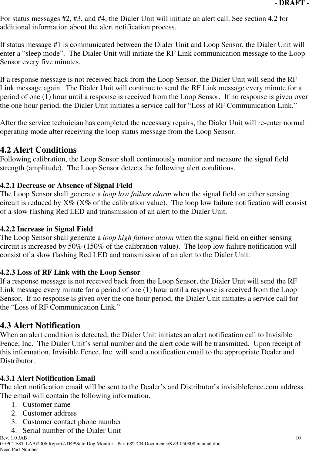
![- DRAFT - Rev. 1.0 JAB 9 G:\PCTEST LAB\2006 Reports\TRP\Safe Dog Monitor - Part 68\TCB Documents\KZ3-050808 manual.doc Need Part Number jack. Plug the phone cable into one of the connectors. Connect the other end of the cable into the house’s phone jack. The additional phone connector jack on the Dialer unit can be used if the customer still wants an active telephone connected to the phone jack. Plug the phone cable from the telephone into the extra phone jack. [Show close up of phone connectors on the Dialer Unit circuit board] 3.3.4 Successful RF Communication Link Before mounting the Dialer Unit to the wall, the RF link status between the Dialer Unit and Loop Sensor should be checked. This should be done in the location where the Dialer Unit will be installed. This can be done by using the Test Mode on the “jumper switch”. OUTLINE THESE INSTRUCTIONS. If the LED status indicator does not show slow flashing green, use the Dialer Unit LED Status Indicator Chart in section 4.3.2 to trouble-shoot the problem. One possible solution may be to locate the Dialer Unit in a different area of the house. 3.3.5 Mounting the Safe Dog Monitor Dialer Unit To mount the Dialer Unit to the wall, first remove the cover of the unit. To remove the cover, hold the unit in one hand, and using your thumb and index finger of your other hand, gently compress the side of the cover plate and remove it. To fasten the Dialer Unit base to the wall, you need two ¾ inch long (19mm), #8, or #10 pan-head sheet metal screws. [Show picture of Dialer unit base, pointing out mounting holes] 3.3.6 Using Battery Back-up Battery back-up is also available via a standard 9V alkaline battery. If the Safe Dog Monitor Loop Sensor is connected to the 12v lead acid battery back-up, the Dialer Unit should also use the battery back-up option to ensure communication if there is a loss of power. [Show picture of Dialer Unit circuit board and placement of 9V battery] 4.0 Normal Operating Mode – Failure Detection After installation and programming are complete, the Safe Dog Monitor will enter normal operating mode. 4.1 Dialer Unit and Loop Sensor Communication The Dialer Unit will send an RF Link message to the Loop Sensor every five (5) minutes. The Loop Sensor will respond to the Dialer Unit confirming the communication link. The Loop Sensor will provide the Dialer Unit with a status message. The status message can be: 1. System OK 2. Wire break detection 3. Loop failure low 4. Loop failure high](https://usermanual.wiki/Radio-Systems/050808/User-Guide-785442-Page-9.png)
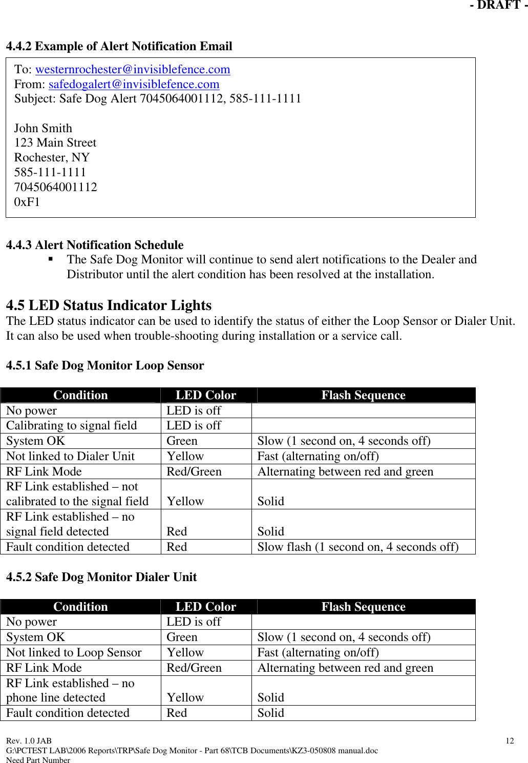
![- DRAFT - Rev. 1.0 JAB 13 G:\PCTEST LAB\2006 Reports\TRP\Safe Dog Monitor - Part 68\TCB Documents\KZ3-050808 manual.doc Need Part Number Low battery Red Slow flash (1 second on, 4 seconds off) Alert call not completed Red Fast (alternating on/off) 5.0 Safe Dog® Monitor Registration The main purpose of the Safe Dog Monitor is to provide proactive customer service in the event of an alert condition. Therefore, completion of the Safe Dog Monitor Registration process is critical to providing the highest level of customer service. 5.1 Registration Process The registration process consists of two phases: 1. Pre-registration – completed by the Invisible Fence Brand Distributor 2. Registration – completed by the Invisible Fence Dealer 5.1.1 Pre-registration This phase of the process occurs when the Dialer Units are shipped to Invisible Fence Brand Dealer locations. Each Invisible Fence Brand Distributor will scan or enter Dialer Unit serial numbers for each Dealer shipment in the Safe Dog Monitor warranty database website. This site can be accessed at [enter site address]. A user name and password is required to access this protected site. This process will assign Dialer Units to specific Invisible Fence Brand Dealer locations. This is the first level of registration. If Invisible Fence, Inc receives a notification call from a Dialer Unit that has only been through both this levels, an email will be sent to the Distributor and Dealer. The email alert notification will only contain the Dialer Unit serial number and the alert condition code. Specific customer information will not be included. For detailed directions on pre-registering the Safe Dog Monitor, please refer to the Safe Dog Monitor Registration Manual. 5.1.2 Registration – Before Installation This phase of the process occurs either before or after installation of the Safe Dog Monitor at a customer’s home. If the Invisible Fence Brand Dealer’s operation process is to “kit” all system components before installation, the registration process can be done before installation. Registration of the Dialer Unit is done within the Safe Dog Monitor warranty database. This site can be accessed at [enter site address]. A user name and password is required to access this protected site. A Safe Dog Monitor section is available to each Invisible Fence Brand Dealer. This section allows the Dealer to register the Safe Dog Monitor and other system components (transmitter, receiver, etc.) to a specific customer. If a customer product “kit” is created, the products can be registered before the actual installation occurs. For detailed directions on registering the Safe Dog Monitor, please refer to the Safe Dog Monitor Registration Manual.](https://usermanual.wiki/Radio-Systems/050808/User-Guide-785442-Page-13.png)
![- DRAFT - Rev. 1.0 JAB 14 G:\PCTEST LAB\2006 Reports\TRP\Safe Dog Monitor - Part 68\TCB Documents\KZ3-050808 manual.doc Need Part Number 5.1.3 Registration – After Installation If “kitting” of customer system components is not done, the registration of the Safe Dog Monitor must be done after installation. During the installation, the serial number of the Dialer must be recorded for entry into the Safe Dog Monitor warranty database. This can be done on the installation contract of installation checklist. When the paperwork is returned to the office, the information can be entered into the Safe Dog Monitor warranty database. This site can be accessed at [enter site address]. A user name and password is required to access this protected site. A Safe Dog Monitor section is available to each Invisible Fence Brand Dealer. This section allows the Dealer to register the Safe Dog Monitor and other system components (transmitter, receiver, etc.) to a specific customer. For detailed directions on registering the Safe Dog Monitor, please refer to the Safe Dog Monitor Registration Manual.](https://usermanual.wiki/Radio-Systems/050808/User-Guide-785442-Page-14.png)