Radio Systems 050808 Safe Dog Monitor/ Dialer Transceiver System User Manual KZ3 050808 manual
Radio Systems Corporation Safe Dog Monitor/ Dialer Transceiver System KZ3 050808 manual
Users Manual

Rev. 1.0 JAB
Safe Dog® Monitor
Installation and Training Manual

- DRAFT -
Rev. 1.0 JAB 2
G:\PCTEST LAB\2006 Reports\TRP\Safe Dog Monitor - Part 68\TCB Documents\KZ3-050808 manual.doc
Need Part Number
Table of Contents
1.0 Product Introduction
1.1 Safe Dog® Monitor System Overview
1.2 Important Precautions and Warning
1.3 Required System Components for Installation
1.4 Product Specifications
1.5 Loop Sensor User Control
1.6 Dialer Unit User Control
2.0 Planning the Safe Dog® Monitor Installation
2.1 Safe Dog® Monitor Loop Sensor
2.2 Safe Dog® Monitor Dialer Unit
3.0 Safe Dog® Monitor Installation Process
3.1 Programming the Safe Dog® Monitor Loop Sensor and Dialer Unit
3.1.1 Programming/Synchronization Procedure
3.2 Safe Dog® Monitor Loop Sensor
3.2.1 Installation Diagram
3.2.2 Mounting the Safe Dog® Monitor Loop Sensor
3.2.3 Routing the Signal Field Wires
3.2.4 Connecting AC Power
3.2.5 Connecting to the Transmitter Battery Back-up
3.2.6 Calibrating the Signal Field to the Loop Sensor
3.3 Safe Dog® Monitor Dialer Unit
3.3.1 Installation Diagram
3.3.2 Connecting Power
3.3.3 Connecting the Phone Line
3.3.4 Successful RF Communication Link
3.3.5 Mounting the Safe Dog® Monitor Dialer Unit
3.3.6 Using Battery Back-up
4.0 Normal Operating Mode – Failure Detection
4.1 Dialer Unit and Loop Sensor Communication
4.2 Alert Conditions
4.2.1 Decrease or Absence of Signal Field
4.2.2 Increase in Signal Field
4.2.3 Loss of RF Link with the Loop Sensor
4.3 Alert Notification
4.3.1 Alert Notification Email
4.3.2 Example of Alert Notification Email
4.3.3 Alert Notification Schedule
4.4 LED Status Indicator Lights
5.0 Safe Dog Monitor Registration
- DRAFT -
Rev. 1.0 JAB 3
G:\PCTEST LAB\2006 Reports\TRP\Safe Dog Monitor - Part 68\TCB Documents\KZ3-050808 manual.doc
Need Part Number
5.1 Registration Process
5.1.1 Pre-registration
5.1.2 Registration – Before Installation
5.1.3 Registration – After Installation

- DRAFT -
Rev. 1.0 JAB 4
G:\PCTEST LAB\2006 Reports\TRP\Safe Dog Monitor - Part 68\TCB Documents\KZ3-050808 manual.doc
Need Part Number
1.0 Product Introduction
This document contains important information regarding the installation and operation of the
Invisible Fence® Brand Safe Dog® Monitor. Prior installation of both the signal field wire and
Invisible Fence Brand transmitter is assumed. Review all instructions before installation and use.
1.1 Safe Dog Monitor System Overview
The Safe Dog Monitor is designed to continuously monitor the signal transmission of an Invisible
Fence Brand transmitter and detect when a change occurs in signal amplitude – specifically, the
detection of a wire break condition. The Safe Dog Monitor will also detect an increase or decrease in
the signal amplitude and an RF Link Communication failure between the Loop Sensor and Dialer
Unit. The Safe Dog Monitor is capable of monitoring the signal of the following Invisible Fence
Brand transmitters:
r ICT 700 Series Transmitters (700, 725, 750, 775)
r ICT 800 Series Transmitters (801, 802, 810)
r Invisible Gate®
r Invisible Mask® II
Before the Safe Dog Monitor is installed, the Invisible Fence Brand pet containment system should
be completely installed and operational.
1.2 Important Precautions and Warnings
Caution: Never install or service any Invisible Fence Brand equipment during a thunderstorm or
electrical storm, or when thunder or lightning are in your area.
1.3 Required System Components for Installation
The following system components are required for installation of the Safe Dog Monitor.
1. Safe Dog Monitor Loop Sensor [Picture of Loop Sensor]
2. Safe Dog Monitor Dialer Unit [Picture of Dialer Unit]
3. Invisible Fence Brand 700 or 800 Series Transmitter, Invisible Gate, or Invisible Mask II
[Picture of 725 and 801 transmitters]
4. Lightning Protection Device (for the Transmitters) – LP 4100/4200 or Max-Dog [Picture of
4100 and Max Dog]
5. AC Adapter – For transmitter and Loop Sensor power supply [Picture of AC adapter]
6. Y-adapter for Loop Sensor power [Picture of Y-adapter]
7. DC Adapter for Dialer Unit power supply [Picture of Adapter]
8. Phone cable [Picture of phone cable included in system pack]
9. 9-volt battery to for battery back-up on the Dialer Unit [Picture of 9-volt included in system
pack]
10. Optional: 12v Lead acid battery-back-up for transmitter and Loop Sensor
11. Optional: Y-adapter for connecting Loop Sensor (Included in system pack, show picture)
1.4 Product Specifications – Overview
The Safe Dog Monitor consists of two main components: the Loop Sensor and the Dialer Unit. The
Loop Sensor is located in close proximity to the Invisible Fence Brand transmitter. The Dialer Unit
must be located near a working phone connection. The Dialer Unit communicates with the Loop

- DRAFT -
Rev. 1.0 JAB 5
G:\PCTEST LAB\2006 Reports\TRP\Safe Dog Monitor - Part 68\TCB Documents\KZ3-050808 manual.doc
Need Part Number
Sensor via a 900 MHz radio frequency signal. If an alert condition is detected, the Dialer Unit
initiates an alert notification to Invisible Fence, Inc. This alert notification is then sent via email to
the appropriate Invisible Fence Brand Distributor and Dealer.
[Picture of both the Loop Sensor and Dialer Unit]
For proper operation, the Loop Sensor and Dialer Unit should never be located more than 250 feet
apart (line of sight). The range may vary due to surrounding environmental conditions such as
physical obstructions. The Loop Sensor and Dialer Unit also need to be synchronized to each other
during installation (See page ___ for further instructions on RF Link Programming).
1.5 Loop Sensor User Controls
The Loop Sensor has a push button that is used for linking to the Dialer Unit, calibrating to the set
signal field, and re-setting to the default condition. [Show close up picture of Loop Sensor t-board
with call-out for the push button]
1. If the Loop Sensor is not linked to the Dialer Unit, and the push button is pressed for less than
two seconds, the Loop Sensor will enter the RF Link Programming mode. The Loop Sensor
will remain in this mode until programming is complete or a period of fifteen seconds has
elapsed.
2. If the Loop Sensor is already linked to the Dialer Unit and the push button is pressed for less
than two seconds, the Loop Sensor will calibrate to the signal field. These values will be used
for determining the presence of a signal reduction/increase/loss/imbalance.
3. Pushing the button with for more than 10 seconds will reset the Loop Sensor to the default
condition.
1.6 Dialer Unit User Control
The Dialer Unit has a push button that is used for either entering the RF Link Programming mode or
re-setting to the initial default condition. [Show close up picture of Dialer t-board with call-out for
the push button and jumper switch]
1. If the push button is pressed for less than two seconds the Dialer Unit will enter the RF Link
Programming mode. The Dialer unit will remain in this mode until programming is complete
or until the RF Link Programming mode has failed.
2. Pushing the button with for more than 10 seconds will reset the Loop Sensor to the default
condition.
The Dialer Unit also is equipped with a “jumper switch” which can be used to test the RF Link during
product installation and set-up.
2.0 Planning the Safe Dog® Monitor Installation
Planning the location of the Safe Dog Monitor components is critical to proper operation and
providing a professional installation. Before permanently mounting any components (Loop Sensor or
Dialer Unit), verify proper operation. Please read all instructions contained in this manual before
installing the Safe Dog Monitor.
2.1 Safe Dog Monitor Loop Sensor
The Loop Sensor should be located on a flat wall surface near the Invisible Fence Brand transmitter.

- DRAFT -
Rev. 1.0 JAB 6
G:\PCTEST LAB\2006 Reports\TRP\Safe Dog Monitor - Part 68\TCB Documents\KZ3-050808 manual.doc
Need Part Number
The Loop Sensor must be installed on the “loop-side” of the lightning protection device (LP
4100/4200). The Loop Sensor should be visible to the customer so they can periodically check the
status of the unit. [Show picture of proper and improper installation]
IMPORTANT NOTE: If the Loop Sensor is installed on the transmitter side of the lightning
protection device, and the lightning protection device fails closed, the signal field could still be
present between the transmitter and lightning protection device, but absent in the actual field.
Under this condition, the Loop Sensor would not detect a fault condition.
2.2 Safe Dog Monitor Dialer Unit
The Dialer Unit should be located near an operational phone jack and 110vAC power source. The
Dialer Unit can be located up to 250 feet from the Loop Sensor. The range may vary due to
surrounding environmental conditions such as physical obstructions. The Dialer Unit should be
visible to the customer so they can periodically check the status of the unit. [Show installation
example near a phone jack and AC outlet]
3.0 Safe Dog® Monitor Installation Process
Please read the entire installation process before attempting to install the Safe Dog Monitor. Pay
careful attention to the sequence of the steps.
3.1 Programming the Safe Dog Monitor Loop Sensor and Dialer Unit
RF Link Programming of the Loop Sensor and Dialer Unit is critical to proper operation of the Safe
Dog Monitor. Without successful programming, the Loop Sensor and Dialer Unit cannot
communicate with each other.
The steps outlined in section 3.1.1 must be followed in order to successfully program the Loop
Sensor and Dialer Unit. Please read through the entire procedure before beginning the process.
3.1.1 RF Link Programming Procedure
Synchronize the Loop Sensor to the Dialer Unit by performing the programming procedure outlined
below:
1. Initiate the RF Link Programming sequence.
a. Ensure that both the Dialer Unit and Loop Sensor are in close proximity to one
another. The recommended location to perform this task is near the location where the
Dialer Unit will be located. Power must be supplied to both units during this process.
2. Initiate the RF Link Programming mode on the Loop Sensor first by pressing and releasing
the push button on the transmitter circuit board. [Show picture pointing out push button on
the t-board of the Loop Sensor] Do not hold the button down longer than two seconds. When
the Loop Sensor enters the RF Link Programming mode, the LED will alternate between the
Red and Green color.
3. Initiate the RF Link Programming mode on the Dialer Unit by pressing and releasing the push
button on the transmitter circuit board. [Show picture pointing out push button on the t-board
- DRAFT -
Rev. 1.0 JAB 7
G:\PCTEST LAB\2006 Reports\TRP\Safe Dog Monitor - Part 68\TCB Documents\KZ3-050808 manual.doc
Need Part Number
of the Dialer Unit]. When the Dialer Unit enters the RF Link Programming mode, the LED
will alternate between the Red and Green color.
4. Upon successful RF Link of the Dialer Unit and Loop Sensor, the LED on both units will now
begin a slow Green flash indicating normal operating mode.
a. If more than 20 seconds elapses during the RF Link Programming process and the
LED’s on both units fail to start the slow Green flash, the procedure has failed. At this
point, repeat the process.
5. Power can now be removed from both units if necessary. Once the Dialer Unit and Loop
Sensor are programmed, the RF Link is stored in the memory of both units.
3.2 Safe Dog Monitor Loop Sensor
3.2.1 Installation Diagram
Install the Loop Sensor in close proximity to the transmitter and lightning protection device.
Distance from the transmitter and battery back up is limited by the length of both Y-adapters.
[Show diagram of typical system installation]
3.2.2 Mounting the Safe Dog Monitor Loop Sensor
To mount the Loop Sensor to the wall, first remove the cover of the unit. To remove the cover, hold
the unit in one hand, and using your thumb and index finger of your other hand, gently compress the
side of the cover plate and remove it. To fasten the Loop Sensor base to the wall, you need two ¾
inch long (19mm), #8, or #10 pan-head sheet metal screws.
[Show picture of Loop Sensor base, pointing out mounting holes and wire channels with call-outs]
3.2.3 Routing the Signal Field Wires
The next step in the installation process is to route the signal field wires coming from the LP 4100
through the wire channels in the Loop Sensor base. [Show diagram] It is important that the wires
remain in the channels when the Loop Sensor is mounted on the wall.
IMPORTANT NOTE: The wire channels on the Loop Sensor are designed to accept 14 AWG
wire with a jacket size of 0.045”. For smaller gauge wire, electrical tape may be required to
hold the signal field wires in the wire channel.
3.2.4 Connecting AC Power
Power to the Loop Sensor is supplied by the AC adapter used to power the Invisible Fence Brand
transmitter. A Y-adapter included in the Safe Dog Monitor system pack (SPSDM-100) or in the Safe
Dog Monitor repair kit (RK-28) is used to provide power to both the transmitter and Loop Sensor. If
the Y-adapter is not used, the small Invisible Fence Brand AC adapter may be used (04-100-0020-
01).
[Show picture/diagram of Y-adapter being used]
3.2.5 Connecting to the Transmitter Battery Back-up
If the installation uses the optional battery back-up for the containment transmitter, the Safe Dog
Monitor Loop Sensor should also be connected to the 12v battery back-up. This is accomplished by
using the battery back-up Y-adapter.
[Show picture/diagram of Y-adapter being used]
- DRAFT -
Rev. 1.0 JAB 8
G:\PCTEST LAB\2006 Reports\TRP\Safe Dog Monitor - Part 68\TCB Documents\KZ3-050808 manual.doc
Need Part Number
3.2.6 Calibrating the Signal Field to the Loop Sensor
IMPORTANT: Remember that the Loop Sensor must be located on the “loop side” of the lightning
protection device. The Loop Sensor should now be mounted on the wall. To calibrate the Loop
Sensor to the signal field, perform the following procedure.
1. RF Link Programming between the Loop Sensor and Dialer Unit must be successfully
completed before calibrating the Loop Sensor to the signal field. See section 3.1 for
additional information.
2. Double-check to make sure the signal field wires are securely placed in the wire channels on
the base of the Loop Sensor case.
3. Apply power to the Loop Sensor
a. The LED status indicator should show XXX.
i. This indicates power is on with no signal field present
4. Apply power to the transmitter
a. Adjust the signal to the appropriate signal field width.
b. The LED status indicator on the Loop Sensor should now show a XXXX indicating
detection of a signal field.
5. Press and release the control button on the Loop Sensor [Show picture of Loop Sensor circuit
board with call-out]. The LED status indicator will be off during the signal field calibration.
6. Once calibration is complete, the LED status indicator will show a slow flashing green
indicating normal operating mode. This process should take no longer than fifteen seconds.
7. Replace the Loop Sensor cover.
3.3 Safe Dog Monitor Dialer Unit
3.3.1 Installation Diagram
Once the Dialer Unit has been successfully linked to the Loop Sensor, and the Loop Sensor has been
calibrated to the signal field, the Dialer Unit can be permanently installed near any working phone
jack. The phone jack should be within 250 feet of the Loop Sensor. An 110vAC outlet is also
required to provide power to the Dialer Unit. The Dialer Unit must be located within six feet of the
outlet due to the length of the power adapter cord.
[Show diagram of typical system installation]
3.3.2 Connecting Power
Power to the Dialer Unit will be supplied by a 10vDC wall adapter (included in the System Pack).
[Show picture of 10vDC adapter]
3.3.3 Connecting the Phone Line
Connect the Dialer to a working phone jack. There are two available phone jack connectors on the
Dialer Unit. Either connector can be used for connecting the Dialer Unit to the wall mounted phone

- DRAFT -
Rev. 1.0 JAB 9
G:\PCTEST LAB\2006 Reports\TRP\Safe Dog Monitor - Part 68\TCB Documents\KZ3-050808 manual.doc
Need Part Number
jack. Plug the phone cable into one of the connectors. Connect the other end of the cable into the
house’s phone jack. The additional phone connector jack on the Dialer unit can be used if the
customer still wants an active telephone connected to the phone jack. Plug the phone cable from the
telephone into the extra phone jack. [Show close up of phone connectors on the Dialer Unit circuit
board]
3.3.4 Successful RF Communication Link
Before mounting the Dialer Unit to the wall, the RF link status between the Dialer Unit and Loop
Sensor should be checked. This should be done in the location where the Dialer Unit will be
installed.
This can be done by using the Test Mode on the “jumper switch”. OUTLINE THESE
INSTRUCTIONS.
If the LED status indicator does not show slow flashing green, use the Dialer Unit LED Status
Indicator Chart in section 4.3.2 to trouble-shoot the problem. One possible solution may be to locate
the Dialer Unit in a different area of the house.
3.3.5 Mounting the Safe Dog Monitor Dialer Unit
To mount the Dialer Unit to the wall, first remove the cover of the unit. To remove the cover, hold
the unit in one hand, and using your thumb and index finger of your other hand, gently compress the
side of the cover plate and remove it. To fasten the Dialer Unit base to the wall, you need two ¾ inch
long (19mm), #8, or #10 pan-head sheet metal screws.
[Show picture of Dialer unit base, pointing out mounting holes]
3.3.6 Using Battery Back-up
Battery back-up is also available via a standard 9V alkaline battery. If the Safe Dog Monitor Loop
Sensor is connected to the 12v lead acid battery back-up, the Dialer Unit should also use the battery
back-up option to ensure communication if there is a loss of power.
[Show picture of Dialer Unit circuit board and placement of 9V battery]
4.0 Normal Operating Mode – Failure Detection
After installation and programming are complete, the Safe Dog Monitor will enter normal operating
mode.
4.1 Dialer Unit and Loop Sensor Communication
The Dialer Unit will send an RF Link message to the Loop Sensor every five (5) minutes. The Loop
Sensor will respond to the Dialer Unit confirming the communication link. The Loop Sensor will
provide the Dialer Unit with a status message. The status message can be:
1. System OK
2. Wire break detection
3. Loop failure low
4. Loop failure high
- DRAFT -
Rev. 1.0 JAB 10
G:\PCTEST LAB\2006 Reports\TRP\Safe Dog Monitor - Part 68\TCB Documents\KZ3-050808 manual.doc
Need Part Number
For status messages #2, #3, and #4, the Dialer Unit will initiate an alert call. See section 4.2 for
additional information about the alert notification process.
If status message #1 is communicated between the Dialer Unit and Loop Sensor, the Dialer Unit will
enter a “sleep mode”. The Dialer Unit will initiate the RF Link communication message to the Loop
Sensor every five minutes.
If a response message is not received back from the Loop Sensor, the Dialer Unit will send the RF
Link message again. The Dialer Unit will continue to send the RF Link message every minute for a
period of one (1) hour until a response is received from the Loop Sensor. If no response is given over
the one hour period, the Dialer Unit initiates a service call for “Loss of RF Communication Link.”
After the service technician has completed the necessary repairs, the Dialer Unit will re-enter normal
operating mode after receiving the loop status message from the Loop Sensor.
4.2 Alert Conditions
Following calibration, the Loop Sensor shall continuously monitor and measure the signal field
strength (amplitude). The Loop Sensor detects the following alert conditions.
4.2.1 Decrease or Absence of Signal Field
The Loop Sensor shall generate a loop low failure alarm when the signal field on either sensing
circuit is reduced by X% (X% of the calibration value). The loop low failure notification will consist
of a slow flashing Red LED and transmission of an alert to the Dialer Unit.
4.2.2 Increase in Signal Field
The Loop Sensor shall generate a loop high failure alarm when the signal field on either sensing
circuit is increased by 50% (150% of the calibration value). The loop low failure notification will
consist of a slow flashing Red LED and transmission of an alert to the Dialer Unit.
4.2.3 Loss of RF Link with the Loop Sensor
If a response message is not received back from the Loop Sensor, the Dialer Unit will send the RF
Link message every minute for a period of one (1) hour until a response is received from the Loop
Sensor. If no response is given over the one hour period, the Dialer Unit initiates a service call for
the “Loss of RF Communication Link.”
4.3 Alert Notification
When an alert condition is detected, the Dialer Unit initiates an alert notification call to Invisible
Fence, Inc. The Dialer Unit’s serial number and the alert code will be transmitted. Upon receipt of
this information, Invisible Fence, Inc. will send a notification email to the appropriate Dealer and
Distributor.
4.3.1 Alert Notification Email
The alert notification email will be sent to the Dealer’s and Distributor’s invisiblefence.com address.
The email will contain the following information.
1. Customer name
2. Customer address
3. Customer contact phone number
4. Serial number of the Dialer Unit
- DRAFT -
Rev. 1.0 JAB 11
G:\PCTEST LAB\2006 Reports\TRP\Safe Dog Monitor - Part 68\TCB Documents\KZ3-050808 manual.doc
Need Part Number
5. Alert code
The above information will only be transmitted to the Dealer and Distributor if the Safe Dog Monitor
Registration process is completed. Review section 5.0 for instructions on completing the registration
process.
- DRAFT -
Rev. 1.0 JAB 12
G:\PCTEST LAB\2006 Reports\TRP\Safe Dog Monitor - Part 68\TCB Documents\KZ3-050808 manual.doc
Need Part Number
4.4.2 Example of Alert Notification Email
4.4.3 Alert Notification Schedule
§ The Safe Dog Monitor will continue to send alert notifications to the Dealer and
Distributor until the alert condition has been resolved at the installation.
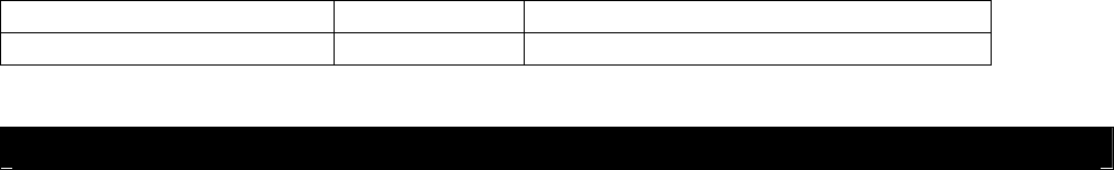
4.5 LED Status Indicator Lights
The LED status indicator can be used to identify the status of either the Loop Sensor or Dialer Unit.
It can also be used when trouble-shooting during installation or a service call.
4.5.1 Safe Dog Monitor Loop Sensor
Condition LED Color Flash Sequence
No power LED is off
Calibrating to signal field LED is off
System OK Green Slow (1 second on, 4 seconds off)
Not linked to Dialer Unit Yellow Fast (alternating on/off)
RF Link Mode Red/Green Alternating between red and green
RF Link established – not
calibrated to the signal field Yellow Solid
RF Link established – no
signal field detected Red Solid
Fault condition detected Red Slow flash (1 second on, 4 seconds off)
4.5.2 Safe Dog Monitor Dialer Unit
Condition LED Color Flash Sequence
No power LED is off
System OK Green Slow (1 second on, 4 seconds off)
Not linked to Loop Sensor Yellow Fast (alternating on/off)
RF Link Mode Red/Green Alternating between red and green
RF Link established – no
phone line detected Yellow Solid
Fault condition detected Red Solid
To: westernrochester@invisiblefence.com
From: safedogalert@invisiblefence.com
Subject: Safe Dog Alert 7045064001112, 585-111-1111
John Smith
123 Main Street
Rochester, NY
585-111-1111
7045064001112
0xF1
- DRAFT -
Rev. 1.0 JAB 13
G:\PCTEST LAB\2006 Reports\TRP\Safe Dog Monitor - Part 68\TCB Documents\KZ3-050808 manual.doc
Need Part Number
Low battery Red Slow flash (1 second on, 4 seconds off)
Alert call not completed Red Fast (alternating on/off)
5.0 Safe Dog® Monitor Registration
The main purpose of the Safe Dog Monitor is to provide proactive customer service in the event of an
alert condition. Therefore, completion of the Safe Dog Monitor Registration process is critical to
providing the highest level of customer service.
5.1 Registration Process
The registration process consists of two phases:
1. Pre-registration – completed by the Invisible Fence Brand Distributor
2. Registration – completed by the Invisible Fence Dealer
5.1.1 Pre-registration
This phase of the process occurs when the Dialer Units are shipped to Invisible Fence Brand Dealer
locations. Each Invisible Fence Brand Distributor will scan or enter Dialer Unit serial numbers for
each Dealer shipment in the Safe Dog Monitor warranty database website. This site can be accessed
at [enter site address]. A user name and password is required to access this protected site.
This process will assign Dialer Units to specific Invisible Fence Brand Dealer locations.
This is the first level of registration. If Invisible Fence, Inc receives a notification call from a Dialer
Unit that has only been through both this levels, an email will be sent to the Distributor and Dealer.
The email alert notification will only contain the Dialer Unit serial number and the alert condition
code. Specific customer information will not be included.
For detailed directions on pre-registering the Safe Dog Monitor, please refer to the Safe Dog Monitor
Registration Manual.
5.1.2 Registration – Before Installation
This phase of the process occurs either before or after installation of the Safe Dog
Monitor at a customer’s home. If the Invisible Fence Brand Dealer’s operation process is to “kit” all
system components before installation, the registration process can be done before installation.
Registration of the Dialer Unit is done within the Safe Dog Monitor warranty database. This site can
be accessed at [enter site address]. A user name and password is required to access this protected
site.
A Safe Dog Monitor section is available to each Invisible Fence Brand Dealer. This section allows
the Dealer to register the Safe Dog Monitor and other system components (transmitter, receiver, etc.)
to a specific customer. If a customer product “kit” is created, the products can be registered before
the actual installation occurs.
For detailed directions on registering the Safe Dog Monitor, please refer to the Safe Dog Monitor
Registration Manual.
- DRAFT -
Rev. 1.0 JAB 14
G:\PCTEST LAB\2006 Reports\TRP\Safe Dog Monitor - Part 68\TCB Documents\KZ3-050808 manual.doc
Need Part Number
5.1.3 Registration – After Installation
If “kitting” of customer system components is not done, the registration of the Safe Dog Monitor
must be done after installation. During the installation, the serial number of the Dialer must be
recorded for entry into the Safe Dog Monitor warranty database. This can be done on the installation
contract of installation checklist.
When the paperwork is returned to the office, the information can be entered into the Safe Dog
Monitor warranty database. This site can be accessed at [enter site address]. A user name and
password is required to access this protected site.
A Safe Dog Monitor section is available to each Invisible Fence Brand Dealer. This section allows
the Dealer to register the Safe Dog Monitor and other system components (transmitter, receiver, etc.)
to a specific customer.
For detailed directions on registering the Safe Dog Monitor, please refer to the Safe Dog Monitor
Registration Manual.

- DRAFT -
Rev. 1.0 JAB 15
G:\PCTEST LAB\2006 Reports\TRP\Safe Dog Monitor - Part 68\TCB Documents\KZ3-050808 manual.doc
Need Part Number
This device complies with part 15 of the FCC Rules. Operation is subject to the following two conditions: (1) This device may not cause harmful
interference, and (2) this device must accept any interference received, including interference that may cause undesired operation.
Unauthorized modifications or changes may void the user’s authority to operate this device.
This equipment complies with FCC Rules Part 68 and the requirements adopted by the ACTA. Located on the bottom of the modem is a product
identifier in the format US: AAAEQ##TXXXX and the Ringer Equivalence Number (REN). You must provide this information to the telephone
company if requested.
The REN is used to determine the number of devices you may legally connect to your telephone line. In most areas, the sum of the REN of all devices
connected to one line must not exceed five. You should contact your telephone company to determine the maximum REN for your calling area.
An FCC compliant telephone cord and modular plug are provided with this equipment, which is designed to connect to the telephone network or
premises wiring using a Part 68 compliant compatible jack. See installation instructions for details. This equipment uses the following USOC jacks:
RJ11C.
If trouble is experienced with this equipment, for repair or warranty information, please contact your Invisible Fence Brand Professional. If this
equipment causes harm to the telephone network, the telephone company will notify you in advance that temporary discontinuance of service may be
required. But if advance notice isn't practical, the telephone company will notify the customer as soon as possible. Also, you will be advised of your
right to file a complaint with the FCC if you believe it is necessary. If the equipment is causing harm to the telephone network, the telephone company
may request that you disconnect the equipment until the problem is resolved.
The telephone company may make changes in its facilities, equipment, operations or procedures that could affect the operation of the equipment. If this
should occur the telephone company will provide advance notice in order for you to make necessary modifications to maintain uninterrupted service.