Radio Thermostat of America CT200R1 Thermostat User Manual CT200 UserGuide REV 0 1
Radio Thermostat Company of America, Inc Thermostat CT200 UserGuide REV 0 1
CT200 UserGuide REV 0.1
RTCOA logo sheet
7aug07
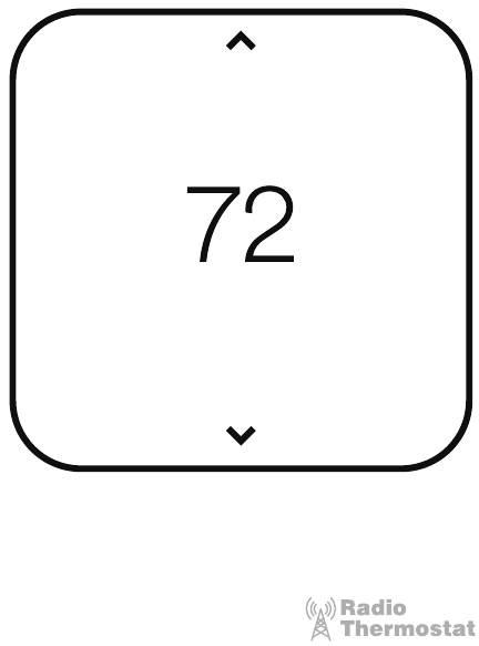
VIVINT ELEMENT THERMOSTAT
USER GUIDE
COMMUNICATING TOUCH SCREEN THERMOSTAT

CT200 INSTALLATION GUIDE
Table Of Contents
Getting Started. . . . . . . . . . . . . . . . . . 3
Interior View 5
Installation Location 6
Wiring . . . . . . . . . . . . . . . . . . . . . . . 8
Mounting Plate 9
Prepare Wires 10
Connecting Wires 11
Power Supply 12
Setup . . . . . . . . . . . . . . . . . . . . . . .14
Connecting to a Z-Wave network 15
Z-Wave and Thermostat Programs 16
Select HVAC & Heat Types 18
Test Installation 20
Wiring Diagrams . . . . . . . . . . . . . . . .22
Detailed Wire Diagram 23
Step By Step Wiring Diagrams 24
Wire Reference Table 28
2

Radio Thermostat
Getting Started
3
Getting Started
Vivint Element CT200 Installation Guide
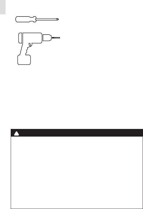
Tools Needed
Small Phillips screwdriver
Drill with ¼" bit (6 mm)
To avoid electrical shock and to prevent damage to the furnace, air condi-
tioner, and thermostat, disconnect the power supply before installing or
servicing the thermostat or any part of the system. This can be done at the
circuit breaker for both the furnance and air conditioner.
• Do not reconnect electricity until work is complete.
• Do not short (jumper) across electric terminals at the control on the
furnace or air conditioner to test the system. This can damage the
thermostat.
• Your thermostat is a precise instrument. Handle it with care.
• All wiring must conform to local codes and ordinances.
• This thermostat is designed for use with 4AA alkaline batteries and/or 24-
volt AC C wire (or a 12- 24 AC or DC source) or millivolt gas systems. Each
thermostat relay load should be limited to 1.0 amp; higher amperage can
cause damage to the thermostat.
! CAUTION
4
Getting Started
Vivint Element CT200 Installation Guide
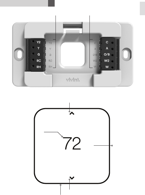
Interior View
Unit Back and Mounting Plate
Unit Front
Wire terminals
Screen
Up Button
Down Button
Bottom Edge Light
Side
Button
5
Getting Started
Vivint Element CT200 Installation Guide
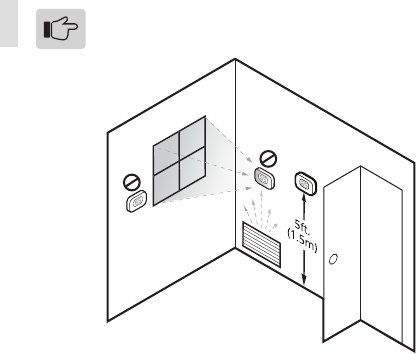
Installation Location
To avoid having to move your wiring to a new location,
mount the thermostat in place of the old thermostat.
• Install the thermostat on an inside wall of an often-used room, about
5 ft. (1.5m) above the oor.
• Do not install where there are unusual heating conditions, such as:
in direct sunlight; near a lamp, radio, television, radiator register,
replace; near hot water pipes in the wall; or near a stove on the
other side of a wall.
• Do not locate in unusual cooling conditions, such as: on a wall
separating an unheated room; or in a draft from a stairwell, door, or
window.
• Do not locate in a damp area. This can lead to corrosion that will
shorten the thermostat’s life.
• Do not locate where air circulation is poor, such as: a corner, an
alcove, or behind an open door.
• Do not install the thermostat until all construction and painting is
complete.
• This thermostat does not require leveling.
6

Radio Thermostat
Wiring
7
Wiring
Vivint Element CT200 Installation Guide
1. Switch o electricity to the heating and cooling systems. This can
be done at the circuit breaker.
2. Remove the cover from the existing thermostat. Check for locking
screws on the side or front that must be loosened rst.
3. Attach provided labels to each wire for identication. Refer to the
lettered terminal where the wires attach; do not use the color of
the wires.
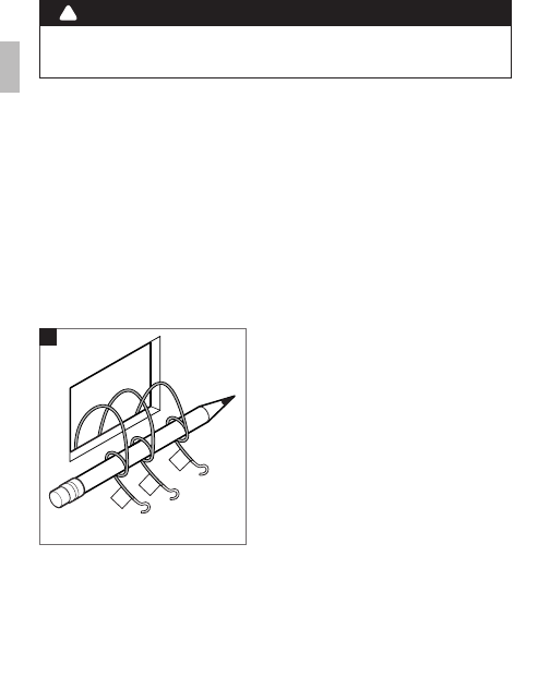
4. Disconnect wires from the existing thermostat, and wind them
around a pencil to keep them from falling back inside the wall.
5. Loosen all mounting screws on the old thermostat and remove it
from the wall.
C
G
W
G
W
C
G
W
4
• Read instructions carefully before removing any wiring from an existing
thermostat.
• Label all wires before disconnecting them form the existing thermostat.
! CAUTION
C
W
RH
G
Y
Preperation
8
Wiring
Vivint Element CT200 Installation Guide
C
W
RH
G
Y
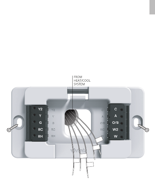
Attaching the Mounting Plate to the wall
1. Carefully pull the labeled wires through the center hole in the
mounting plate.
2. Position thermostat for best appearance to cover the hole in the
wall.
3. Mark rst and drill a ¼ in. (6mm) hole at each screw location.
4. If you are mounting the Thermostat to sheet rock or if you are
using the old mounting holes, use the plastic anchors provided.
5. Attach the Thermostat to the wall with the screws provided.
9
Wiring
Vivint Element CT200 Installation Guide
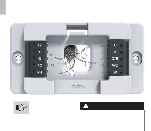
Prepare Wires
Make sure your wires are labeled. If necessary, nd the “other
end” connection for each wire on your heating or air conditioning
equipment and note the label there.
1. Fan out wires so that they are aligned with their terminals.
2. Do not bunch wires in front of the mounting plate. Feed any slack
back into the wall.
Follow these guidelines for safe and secure wire connections:
• Use at least 2.6 in. of wire for each of your connections to the
Thermostat.
• If you do not have enough wire, splice additional wire to allow
enough slack.
• Terminals accept wires from 16-22 awg.
• Remove 1/8 in. insulation from the tip of each wire.
• Take care not to damage the labels for each wire.
! CAUTION
Do not allow wires to touch
each other or other parts on
the thermostat.
If you have both RH
and RC connections,
you must set the RC/
RH Switch to OPEN. If you do
not have both connections,
set the switch to CLOSED.
C
W
RH
G
Y
10
Wiring
Vivint Element CT200 Installation Guide
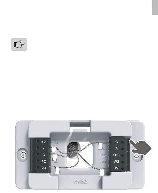
Connecting Your Wires
Reference the Detailed Wire Diagram on page 23 to identify your
wiring diagram and set-up information. If necessary, contact
customer support for help.
1. Connect a labeled wire only to a matching lettered terminal.
2. Press the lever next to the terminal letter, then insert the wire in
the terminal well.
3. Make sure to insert the wire into the terminal well as far as it will
go, then release the lever. The wire should be secure and not pull
free easily.
The Thermostat can be externally powered with a power
source rated from 12V to 24V, AC or DC, at 100ma or
greater. If used, connect to the C and RH terminals (no
polarity).
The 24VAC “C” wire is the other side of the 24VAC heating
transformer and can be found where the other thermostat
wires connect at the wall or at the furnace. Do not use the
common or ground side of the line voltage.
The Thermostat runs on 4 AA alkaline batteries, the C wire
(if available), or both batteries and the C-wire. If you do not
have a C wire, you can run a new wire from the HVAC or
use a standard 12-24V [AC or DC] wall transformer.
The C-wire is optional but preferred for all installations.
C
W
RH
G
Y
Example of 5 Wire
Heat/Cool System 11
Wiring
Vivint Element CT200 Installation Guide
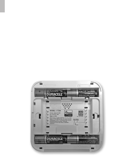
Battery Installation
Power Supply
While the thermostat can run without batteries on C-wire power,
you should install batteries as well to provide power to the unit
during outages. See the Thermostat Battery Cautions.
1. Install four (4) AA alkaline batteries following the marked polarity
in the battery compartments. Insert the battery negative end rst
against the spring, then push the positive end in.
2. With all the wires connected and the unit attached to the wall, it
is time to turn the AC power back on. Reconnect the power at the
breaker you used to switch it o. The Thermostat will power-up in
the OFF mode.
3. Your Thermostat is not yet congured to operate your HVAC
system. You must now connect your thermostat to a Z-Wave
Network and congure the HVAC and Heat Source settings.
12
Wiring
Vivint Element CT200 Installation Guide
• Always use new Alkaline batteries.
• Do not use rechargeable batteries of any type. They will not operate the
thermostat properly and may lead to damage.
• Do not mix old and new batteries.
• Do not mix battery types, for example Lithium with Alkaline.
• Do not dispose of batteries in re. Batteries may explode or leak.
• Always replace the batteries as soon as the “Low Batt” warning ashes. The
thermostat is a battery-powered device; you should replace the batteries
before they run out, as failure to replace batteries can result in excessive
heating or cooling of your house.
• Always replace the batteries once a year, even if the “Low Batt” indicator
does not ash. Replacing the batteries also helps to prevent leakage that
can corrode and damage the thermostat.
• If you are leaving your home for a month or more, you should replace the
batteries as a precaution against battery failure in your absence.
• Failing to replace the batteries when necessary could cause the thermo-
stat to lose power or malfunction. If the thermostat loses power, then the
thermostat will not control the temperature, which could result in your HVAC
system not functioning as you intended and lead to possible damage from
excessive heating or cooling.
• If the thermostat batteries fail with the heat OFF, this can result in NO HEAT
and possible frozen or broken pipes and water damage.
• If the thermostat batteries fail with the cool OFF, this can result in NO COOL
and could cause possible damage or excessive temperatures.
! THERMOSTAT BATTERY CAUTIONS
13

Vivint Element CT200 User Guide
3Setup
14
Setup
Vivint Element CT200 Installation Guide
You must connect the Thermostat to a Z-Wave network.
This unit cannot operate without a network connection.
Connecting the Thermostat to a Z-Wave® Network
The Vivint Element Thermostat is a Z-Wave® compliant thermostat.
It has an onboard radio that can be connected to an existing
Z-Wave® network. This device can be used on a network with
products from dierent vendors.
1. Set your primary controller to INCLUDE mode to add the
thermostat as a node on your network (see your specic
controller’s User Manual for detailed instructions).
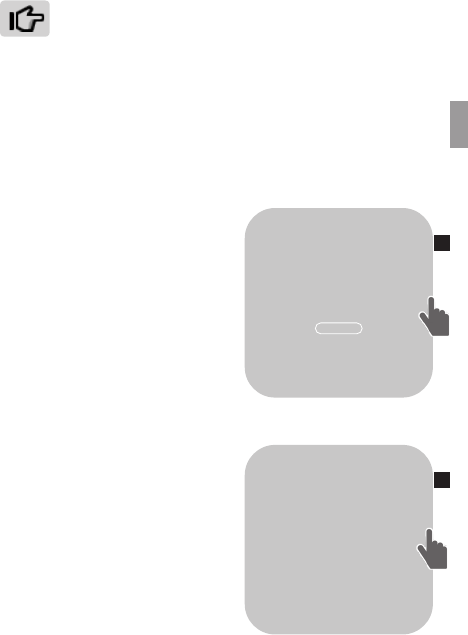
2. The Thermostat main screen
shows a welcome message. Press
the SIDE button to continue.
3. When your primary controller
is ready to connect to the
Thermostat, press the SIDE
button to connect. This initiates
the network connection process.
The Thermostat’s screen says
“Connecting.”
• If the connection fails, the
screen says “Connection failed.”
Press the SIDE button to try connecting again.
5. When the Thermostat has
successfully joined a Z-Wave
network, the screen displays the
message “Connected! Complete
your setup on the VIVINT panel.”
Press the SIDE button to continue.
6. The Thermostat displays the
Home screen, with the device
status of “OFF” and the current
room temperature. You can now
congure the thermostat to work
with your system.
Your primary controller indicates that the thermostat was
successfully added to its network (see your specic controller’s User
Manual for details).
70
OFF
OK
HELLO.
SET UP YOUR
ELEMENT
THERMOSTAT
THROUGH THE
VIVINT PANEL
2
6
15

Setup
3
Vivint Element CT200 Installation Guide
Z-Wave and Power Supply
The thermostat’s node type is xed when it connects to
the Z-Wave network; if the C-Wire is not connected and is
only battery-powered when connecting to the network, the
thermostat will remain a frequent listening routing slave
(FLiRS) node until it is removed from the network.
When your thermostat is running on battery power, the Z-Wave
radio will turn o to help conserve battery life. The Thermostat
Z-Wave radio module supports Z-Wave beaming, which allows other
devices in the network to wake up the Z-Wave module and accept
commands and then go back to sleep.
When your thermostat is running on C-Wire power, the Z-Wave radio
will stay on and actively help route messages within the Z-Wave
network. The thermostat’s node type is xed when it connects to
the Z-Wave network; if the C-Wire is present and powered when
connecting to the network, the thermostat will remain an always-
listening node until it is removed from the network.
Z-Wave and Thermostat Programs
You must connect the Thermostat to a Z-Wave network. This unit
cannot operate without a network connection. When you are
paired to a Z-Wave system, the Z-Wave application on your device
controls your thermostat’s programs. You can still temporarily
override settings on the thermostat itself, but otherwise you control
it remotely.
16

Setup
Vivint Element CT200 Installation Guide
Units
Humidity
Display
Info
Installer
SETTINGS
Navigating the Vivint Element Screens
• Use the UP and DOWN buttons to move the cursor on the screen.
• Use the SIDE button to make a selection or scroll through options.
• To go back to a previous screen, highlight the arrow at the top of
the screen and press the SIDE button.
• After conguring these settings, on the Home screen, press the
side button to turn the system on. Press the side button repeatedly
to cycle through modes.
To return to the Home screen:
• Use the arrow (multiple presses)
• Press and hold the SIDE button for one (1) second
• Wait 10 seconds for the device to sleep, then press any button to
wake it again.
17

Setup
3
Vivint Element CT200 Installation Guide
Selecting HVAC & Heat Types
1. From the Thermostat’s Home
screen, press and hold the
SIDE button for 3 seconds.
The Settings menu opens.
2. Highlight Installer, then press
the SIDE button. The Install
Settings menu opens.
3. Highlight Equipment, then
press the SIDE button. The
Equipment menu opens.
4. Highlight Heating, then press
the SIDE button. The Heating
menu opens.
5. Under Heating Type, press
the SIDE button until your
heating type is displayed:
Forced Air, Heat Pump,
Hydronic, or Radiator.
6. Under Fuel, press the SIDE
button until your heating
fuel is displayed: Natural
Gas, Propane, Fuel Oil, or
Geothermal and Electric. For
Heat Pump systems, this eld
is labeled Aux. Fuel.
7. Under Stages, press the
SIDE button until your
system’s heating stage type is
displayed: 1 (single), 2 (dual),
1 + Auxiliary, or 2 + Auxiliary.
For Heat Pump systems, this
eld is labeled Aux. Stages.
Note: Auxiliary stages are only
available if you select Heat Pump
as the heating type.
Selecting Heat Pump Settings
1. From the Thermostat's Home
screen, press and hold the
SIDE button for 3 seconds.
The Setting menu opens.
2. Highlight Installer, then press
the SIDE button. The Install
Settings menu opens.
3. Highlight Equipment, then
press the SIDE button. The
Equipment menu opens.
4. Highlight Heat Pump, then
press the SIDE button. The
Heat Pump menu opens.
5. Highlight Wire, then select the
letter corresponding to the
terminal the Heat Pump is
connected to: O or B.
6. Under Stages, press the
SIDE button until your
system's heating stage type
is displayed: 1 (single), or 2
(dual).
HEATING
TYPE
FUEL
Forced Air
Natural Gas
1
STAGES
Heat Types
18

Setup
Vivint Element CT200 Installation Guide
Selecting Cooling Type
1. From the Thermostat’s Home
screen, press and hold the
SIDE button for 3 seconds. The
Settings menu opens.
2. Highlight Installer, then press
the SIDE button. The Install
Settings menu opens.
3. Highlight Equipment, then
press the SIDE button. The
Equipment menu opens.
4. Highlight Cooling, the press
the SIDE button. The Cooling
menu opens.
5. Under Type, press the SIDE
button until your Cooling type
is displayed: Air Conditioning,
Heat Pump, or Evaporate.
6. Under Stages, press the SIDE
button until the number of
stages your system uses is
displayed: 1(single) or 2 (dual).
Selecting Humidity Settings
1. From the Thermostat’s Home
screen, press and hold the
SIDE button for 3 seconds. The
Settings menu opens.
2. Highlight Installer, then press
the SIDE button. The Install
Settings menu opens.
3. Highlight Equipment, then press
the SIDE button. The Equipment
menu opens.
4. Highlight Humidity, the press
the SIDE button. The Humidity
menu opens.
5. Under Type, press the SIDE
button until the type of humidity
system you have is displayed:
None, Humidier, Dehumidier,
or Air Conditioner.
6. Under Activation, press the
SIDE button until the method
your humidity system uses is
displayed: W(ith) Heating, W(ith)
Cooling, or Independent.
7. Under Fan, press the SIDE
button until the fan option
your humidity system uses is
displayed: Active or Inactive.
COOLING
TYPE
Air Con.
1
STAGES
Cooling
HUMIDITY
TYPE
ACTIVATION
None
W/ Heating
Active
FAN
Here are the Humidity values:
Humidity Type
o None
o Humidier
o Dehumid.
o Air Con.
Activation
o W/ Heating
o W/ Cooling
o Independent
Fan
o Active
o Inactive
Humidity 19
Setup
3
Vivint Element CT200 Installation Guide
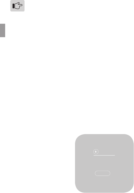
Test Installation
If you have a heat pump, leave the Thermostat in O mode
for 4 (four) minutes before checking Cool.
Do not operate AC if the outside temp is below 65°F.
To Check Heat
The heating and cooling tests
run for up to 30 minutes.You
can stop a test at any time
by selecting the arrow and
pressing the SIDE button.
1. From the Thermostat’s Home
screen, press and hold the
SIDE button for 3 seconds.
The Settings menu opens.
2. Highlight Installer, then press
the SIDE button. The Install
Settings menu opens.
3. Highlight Testing, then press
the SIDE button. The Testing
menu opens.
4. Highlight Heating, then press
the SIDE button. The Heat
Test menu opens.
5. Highlight START, then press
the SIDE button. The Ther-
mostat screen displays the
following:
• HEAT TIME: how long the
test has been running in
minutes and seconds
• ACTIVE: the wires the
system is using to com-
municate with the heating
system (example: W, G)
• CHANGE: the amount
of temperature change
caused during the test
(example: +3.4°)
6. Wait for the test to end, or
highlight the back arrow
and press the SIDE button.
A test of a successfully
functioning heating system will
show a rise in the temperature,
as well as the proper wires
indicated as being active. If the
temperature appears to drop, or
the wrong wires are indicated as
being active, the test indicates
a problem with the Thermostat
installation. Check the wire
connections and run the heating
test again.
HEAT TEST
STOP
HEAT TIME: 18:24
ACTIVE: W, G
CHANGE: +3.4°
20

Setup
Vivint Element CT200 Installation Guide
To Check Cool
1. From the Thermostat’s Home
screen, press and hold the
SIDE button for 3 seconds.
The Settings menu opens.
2. Highlight Installer, then press
the SIDE button. The Install
Settings menu opens.
3. Highlight Testing, then press
the SIDE button. The Testing
menu opens.
4. Highlight Cooling, then press
the SIDE button. The Cool
Test menu opens.
5. Highlight START, then
press the SIDE button. The
Thermostat screen displays
the following:
• COOL TIME: how long the
test has been running in
minutes and seconds
• ACTIVE: the wires the
system is using to com-
municate with the cooling
system (example: Y, G)
• CHANGE: the amount
of temperature change
caused during the test
(example: -2.6°)
6. Wait for the test to end, or
highlight the back arrow
and press the SIDE button.
A test of a successfully
functioning cooling system
will show a drop in the
temperature, as well as the
proper wires indicated as
being active. If the temperature
appears to rise, or the wrong
wires are indicated as being
active, the test indicates a
problem with the Thermostat
installation. Check the wire
connections and run the cooling
test again.
COOL TEST
STOP
COOL TIME: 19:59
ACTIVE: Y, G
CHANGE: -2.6°
21

Vivint Element CT200 User Guide
4Wiring Diagrams
22
Wiring Diagrams
Vivint Element CT200 Installation Guide
R
Y
G
CBO
RG
CBOYn
Wn
Yn
Wn RG
C
CWR
HVAC
CWRGWRG
CY
G
CRH
WY
RC
HVAC
HVAC
HVAC
HVAC
HVAC
HVAC
C W RC W R GC W Y R G C W Y RH RC
G
WIRES
WIRES WIRES
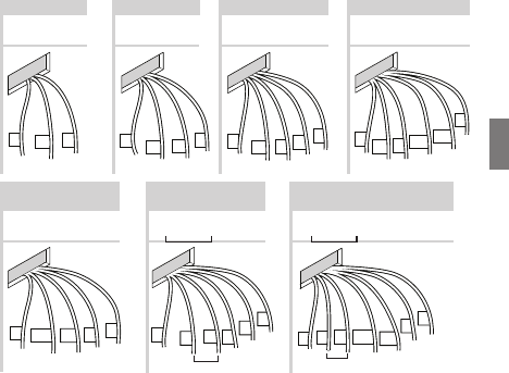
Multi-stage Heat Pump
w/ Multi-stage Aux Heat
C Wn Yn R G
WIRES
Multi-stage Cool
Multi-stage Heat
3 Wire Heat 4 Wire Heat 5 Wire Heat/Cool 6 Wire Heat/Cool
C B or O Y R G C B or O AUXn Yn R G
WIRES WIRES WIRES
Go to Page 19 Go to Page 19 Go to Page 19 Go to Page 20
Go to Page 20 Go to Page 21 Go to Page 21
or
or
4 Wire Heat Pump
w/o Aux Heat
Detailed Wiring Diagrams
23
Wiring Diagrams
4
Vivint Element CT200 Installation Guide
Step-By-Step Wiring Diagrams
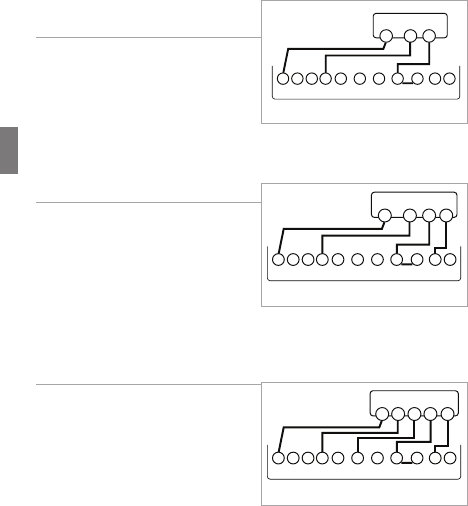
3 Wire Heat GAS MILLIVOLT or
24VAC System
1. Connect the R (or RH) wire to the
RH terminal. This connects the
heat power.
2. Connect the W wire to the W
terminal. This connects the heat.
3. If available, connect the C wire to
the C terminal.
4. Go to “Connect Your Wires” on page 9.
4 Wire Heat
1. Connect the R (or RH) wire to the
RH terminal. This connects the
heat power.
2. Connect the W wire to the W
terminal. This connects the heat.
3. Connect the G wire to the G
terminal. This connects the fan.
4. If available, connect the C wire to the C terminal.
5. Go to “Connect Your Wires” on page 9.
5 Wire Heat/Cool
1. Connect the W wire to the W
terminal. This connects the heat.
2. Connect the Y wire to the Y
terminal. This connects the
cooling compressor.
3. Connect the RH or R wire to the
RH terminal. This connects the
power.
4. Connect the G wire to the G terminal. This connects the fan.
5. If available, connect the C wire to the C terminal.
6. Go to “Connect Your Wires” on page 9.
POWER
HVAC SYSTEM
THERMOSTAT
CBOW YY2RHRC GAW2
W R
C
POWER
HVAC SYSTEM
THERMOSTAT
CBOW YY2RHRC GAW2
W R
CG
POWER
HVAC SYSTEM
THERMOSTAT TERMINALS
CBOW YY2RHRC GAW2
W R
CGY
24
Wiring Diagrams
Vivint Element CT200 Installation Guide
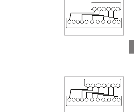
6 Wire Heat/Cool
1. Connect the W wire to the W
terminal. This connects the heat.
2. Connect the Y wire to the Y
terminal. This connects to the
cooling compressor.
3. Disconnect the RC and RH
terminals by removing the
Jumper Wire.
4. Connect the RH wire to the RH terminal and the RC wire to the RC
terminal. This connects power.
5. Connect the G wire to the G terminal. This connects the fan.
6. If available, connect the C wire to the C terminal.
7. Go to “Connect Your Wires” on page 9.
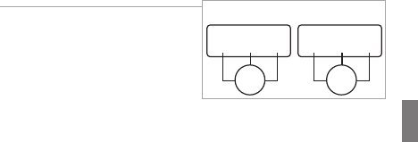
Multi-stage Heat & Multi-Stage Cool
The CT200 can handle up to 2
stages of HEAT and 2 stages of
COOL.
1. Connect the W and W2 wires to
the W and W2 terminals. This
connects the stages of HEAT.
2. Connect the Y and Y2 wires to
the Y and Y2 terminals. This
connects the stages of COOL.
3. Connect the RH or R wire to the RH terminal. This connects the
power.
4. Connect the G wire to the G terminal. This connects the fan.
5. If available, connect the C wire to the C terminal.
6. Go to “Connect Your Wires” on page 9.
POWER
HVAC SYSTEM
THERMOSTAT TERMINALS
CBOW YY2RHRC GAW2
W G
YRHRC
C
*RC and RH disconnected
POWER
HVAC SYSTEM
THERMOSTAT TERMINALS
CBOW YY2RHRC GAW2
W G
YY2R
CW2
25
Wiring Diagrams
4
Vivint Element CT200 Installation Guide
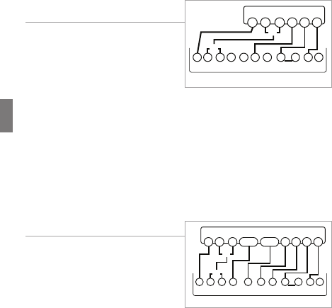
4 Wire Heat Pump (heat/cool)
without Auxiliary Heat
1. Connect the O wire to the O
terminal or the B wire to the
B terminal. This connects the
change-over valve. If you have
both O and B, connect only the
O wire to the O terminal and DO
NOT connect B to B terminal (see the Wire Reference Table on
page 23 for Trane terminal labels).
2. Connect the Y wire to the Y terminal. This connects the
compressor.
3. Connect the R wire to the RH terminal. This connects the power.
4. Connect the G wire to the G terminal. This connects the fan.
5. If available, connect the C wire to the C terminal.
6. Go to “Connect Your Wires” on page 9.
Multi-stage Heat Pump with
Multi-Stage Aux Heat
The CT200 can handle up to 2
stages of Pump compression and 2
stages of AUX heat.
1. Connect O wire to the O terminal
or the B wire to the B terminal.
This connects the change-over
valve. If you have both O and B,
connect only the O wire to the O terminal and DO NOT connect
B to B terminal (see Wire Reference Table on page X for Trane
terminal labels.).
2. Connect the AUX 1 and AUX 2 wires to the AUX 1 and AUX 2
terminals. This connects the auxiliary heat.
3. Connect the Y and Y2 wires to the Y and Y2 terminals. This
connects the compressor.
4. Connect the R wire to RH terminal. This connects the power.
5. Connect the G wire to the G terminal. This connects the fan.
6. If available, connect the C wire to the C terminal.
7. Go to “Connect Your Wires” on page 9.
POWER
HVAC SYSTEM
THERMOSTAT TERMINALS
CB OW YY2RHRC GAW2
BG
OY R
C
or
or
POWER
HVAC SYSTEM
THERMOSTAT TERMINALS
CBOW YY2RHRC GAW2
BG
OY R
C
or
or
Y2AUX2AUX1
26
Wiring Diagrams
Vivint Element CT200 Installation Guide
Accessory Wiring
Zoned Hot Water Heat
For Solenoid or Motor valves,
connect the wires based on the
diagrams to the correct terminal
on the CT200. When controlling a
hydronic heating system, congure
the thermostat as HVAC Type =
Normal with Heat Type = Gas.
• USE ONLY IN HEAT MODE.
• The CT200 must be powered by 24v ac.
The third wire on your valve may be called 6, Y, or G (see the Wire
Reference Table on page 23.
CT102
RH AW
MOTOR VALVE
RH
WA
CT102
RH AW
SOLENOID VALVE
RH
AW
27

Wiring Diagrams
4
Vivint Element CT200 Installation Guide
Wire Reference Table
Possible
Wires
What They Control
R or V or VR RH and RC Single power for HEAT and COOL
RH or 4 RH Power for HEAT (RH not connected to RC jumper clip
removed)
RC RC Power for COOL (RH not connected to RC jumper clip
removed)
W W 1st stage HEAT or 1st stage auxiliary heat
W2 W2 2nd stage HEAT or 2nd stage auxiliary heat
W3 W3 3rd stage HEAT or 2nd stage of 2 stage auxiliary heat
Y Y COOL control or 1st stage compression for heat pump
Y2 Y2 2nd stage COOL control or 2nd stage compression for
a heat pump
G or F G FAN control
C or X C 24VAC power (to power thermostat) NOTE: TRANE uses B
for this connection
HH External Humidier
DH DH External De-Humidier
EX EX external fresh air bae
BB Heat pump changeover (cool to heat, powered in heat)
O O Heat pump changeover (heat to cool, powered in cool)
B and O
IMPORTANT: If there are both B and O wires (Trane pump
products) DO NOT CONNECT B to B terminal. Instead,
connect B to C terminal. If not a Trane product, tape o B.
En/a Emergency heat (do not connect, tape o)
Ln/a System monitor (do not connect, tape o)
Tn/a Outdoor sensor (do not connect, tape o)
28

Wiring Diagrams
Vivint Element CT200 Installation Guide
Lennox Heat Pump
V or VR or R RH Power for HEAT
M or Y Y COOL control
Y or W or W2 W2 2nd stage HEAT
F or G G Fan control
R or O O
X or X2 or C C
Trane Products [American Standard]
B C 24VAC power (to power thermostat)
X2 Emergency heat. Do not connect, tape o.
Zoned Hot Water
2 wire
R RH
W W
Motor Driven Valves
3 Wire
R or 5 RH (power)
W or 4 W (heat ON)
Y or G or 6 (the
3rd wire) A (heat OFF)
Solenoid Valves
3 Wire
R RH (power)
W A (heat ON)
Y or G
(the 3rd wire) W (heat OFF)
29

CT200 OPERATION GUIDE
Product Overview . . . . . . . . . . . . . . . . . . . . 30
Exterior View 32
Screens
Home Screen 33
Outside Temp Screen 34
Menu Screen
Settings Screen
Compressor Protection 35
Settings . . . . . . . . . . . . . . . . . . . . . . . . . . . .36
Units 37
Humidity
Display 38
Info
Installer 39
Equipment
Comfort
Calibration 40
Cycling
Staging 41
Network 41
Link
Reset 42
Testing
Reset 43
Restart
Reset
Other Device Information . . . . . . . . . . . . . . 44
Low Battery Warning
Network Disconnected
30

Radio Thermostat
Product Overview
31
Vivint Element CT200 Operation Guide
Product Overview
5
Exterior View
Screens
Navigating the Vivint Element screens
• Use the UP and DOWN buttons to move the cursor on the screen.
• Use the SIDE button to make a selection or scroll through options.
• To go back to a previous screen, highlight the arrow at the top of
the screen and press the SIDE button.
To return to the Home screen
• Use the arrow (multiple presses)
• Press and hold the SIDE button for one (1) second
• Wait 10 seconds for the device to sleep, then press any button to
wake it again.
Units
Humidity
Display
Info
Installer
SETTINGS
32
Vivint Element CT200 Operation Guide
Product Overview
Home Screen
70
69
Mode
Target Temp
Room Temp
This is the default screen on the Thermostat. Anytime the unit wakes
from sleep (or senses you approaching, if the sensor is enabled),
the screen lights up and displays the system’s mode (top), the target
temperature (center), and the current room temperature (bottom).
When in Heat mode, the light bar at the bottom of the unit glows
red. When in Cool mode, it glows blue. When the unit is o, the light
bar does not glow. When the system is actively heating or cooling,
the colored glow ickers.
TIP: If your system is in a heating and cooling mode, press the SIDE
button once to see the other target temperature. Pressing SIDE
again opens the Menu screen.
• To see this screen, press and hold the SIDE button for one (1)
second; or wait 10 seconds for the device to sleep, then press any
button to wake it again. If you are in another menu, you can also
use the arrow at the top of the screen to go back until you get to
the Home screen.
• To temporarily change the target temperature, press up/down. The
system will meet the target temperature until the next program
period starts or you change the system mode.
33
Vivint Element CT200 Operation Guide
Product Overview
5
Outside Temp Screen
This screen displays the outside
temperature and inside humidity
(in %), and lets you put the system
into Vacation mode.
To see this screen, press the SIDE
button twice.
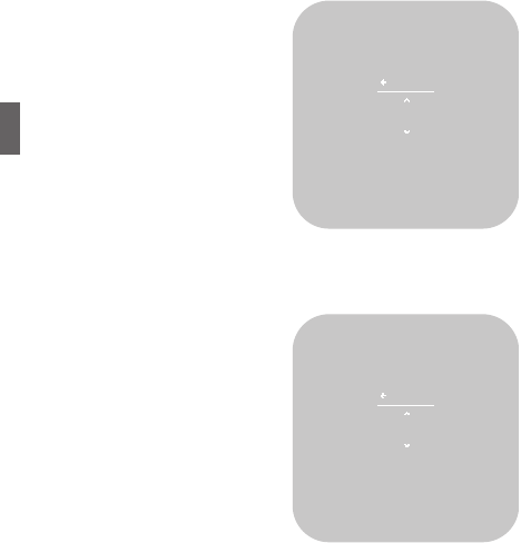
Menu Screen
This screen enables you to change
the mode (heat/cool/o) and fan
operation (auto/on/15 min/30
min/1 hr).
To see this screen, from the
Home screen, press the SIDE
button once.
If your system is in a heating and
cooling mode, press the SIDE
button twice.
Settings Screen
This screen enables you to adjust
the Thermostat’s settings, such
as display units (°F or °C), target
humidity levels, how the display
activates, see information about
the Thermostat, and adjust
installation settings.
To see this screen, from the Home
screen, press and hold the SIDE
button for three (3) seconds.
60°
25%
INSIDE
HUMIDITY
OUTSIDE
TEMPERATURE
Vacation
Cool
15 min 30 min 1 hr
Heat&CoolHeat
Auto
Back
Units
Humidity
Display
Info
Installer
SETTINGS
34

Vivint Element CT200 Operation Guide
Product Overview
Z-Wave and Thermostat Programs
The Thermostat must be connected to a Z-Wave network in order to
operate. Use your Z-Wave application to adjust the heating and cool-
ing programs that the Thermostat uses to run your system. You can
temporarily override target temperatures and change system modes
from the thermostat, but you must use the Z-Wave application to
make permanent changes to programs.
Compressor Protection
The Thermostat has a minimum cycle time of four (4) minutes to
protect your compressor from excessive wear from responding to
thermostat changes. The Home screen shows an hour glass and the
message “Please Wait”. The compressor will not come on until the
four-minute delay is over.
35

Vivint Element CT200 User Guide
6Customization
36

Customization
Vivint Element CT200 Operation Guide
The Settings screen provides access to many features and settings of
the Thermostat. Features you can control on the Settings screen are
ºF / ºC display, humidity targets, display behavior, information about
the Thermostat, and installer settings. The following pages provide
detailed information about each of these settings.
Units
The Thermostat can display either
Fahrenheit or Celsius temperature
units. The Thermostat can display
room temperatures in a range
from 28°F to 99°F (-2°C to 37°C)
with increments of 0.5° (F or C).
1. From the Home screen, press
and hold the SIDE button for
three (3) seconds.
2. Press DOWN to highlight Units,
then press the SIDE button. The
currently selected option has a
check mark next to it.
3. Using the UP or DOWN buttons,
select an option, then press the SIDE button to conrm.
Humidity
This screen is only available if
your system includes humidity
controlling equipment.
1. From the Home screen, press
and hold the SIDE button for
three (3) seconds.
2. Press DOWN to highlight
Humidity, then press the SIDE
button. The current Humidity
Target Level percentage
displays. Every 10 seconds,
the display shows the target
temperature associated with
the humidity value.
3. Press UP or DOWN to set a new target humidity percentage, then
press the SIDE button to conrm.
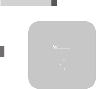
TAP SIDE BUTTON
TO GO BACK
45%
HUMIDITY
TARGET LVL
UNITS
Farenheit
Celcius
37

Customization
6
Vivint Element CT200 Operation Guide
Display
The Thermostat display can
operate in one of two modes:
Approach or Button Tap.
Approach means that the device’s
display will automatically turn
on when it senses you approach
within 4 (four) feet of the unit.
Button Tap means that you will
have to press one of the buttons
on the unit to wake the display.
1. From the Home screen, press
and hold the SIDE button for
three (3) seconds.
2. Press DOWN to highlight Display, then press the SIDE button. The
current Display On behavior has a check mark next to it.
3. Press UP or DOWN to select a behavior, then press the SIDE
button to conrm.
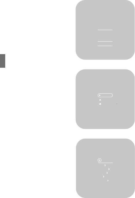
Info
Information about the Thermostat device includes:
POWER: The power supply the
unit is currently using
(batteries, C-wire, and/or
transformer).
BATTERY: How much battery
power is currently left, if
batteries are installed in
the unit.
HEATING: The heating setting the
system is currently using.
ACTIVE RELAYS: The wires
currently being used by
the system.
NETWORK: Whether or not the unit is currently connected to a
Z-Wave network.
SOFTWARE: The current software and rmware versions the unit is
using.
POWER
24VAC
BATTERY
85%
HEATING
HEAT PUMP
AUX. HEAT
ACTIVE RELAYS
Y, O, G
NETWORK
CONNECTED
SOFTWARE
D-V1.23
Z-V1.23
INFO
Approach
Button Tap
DISPLAY ON:
38

Customization
Vivint Element CT200 Operation Guide
1. From the Home screen, press and hold the SIDE button for three
(3) seconds.
2. Press DOWN to highlight Info, then press the SIDE button.
Information about the Thermostat displays.
3. Press UP or DOWN to scroll through the available information.
Installer
Installer settings control the following Thermostat functions:
EQUIPMENT: heating, cooling, humidity control, and fan behavior
COMFORT: swing, dierential, and other settings
NETWORK: the Thermostat’s connection to a Z-Wave Network
TESTING: the Thermostat’s connection to your equipment
RESET: resetting the Thermostat’s software to factory default
EQUIPMENT
The Equipment settings menu is
typically used during installation
of the Thermostat. The options in
this menu enable you to set the
heating, cooling, humidity control,
and fan equipment behavior.
See the Installation Guide’s Setup section for information on setting
those options.
COMFORT
Comfort settings enable you to control:
CALIBRATION: Osets the unit’s temperature display
CYCLING: This feature enables you to set the acceptable variance
in temperature between the Thermostat’s setting and the
current room temperature before the heating or cooling
system will turn on. The Cycling range can be from 0.5 to
4.0F (.25 to 2C). For example, if Cycling is set to 2.0°F and
the Thermostat is set to 70°F target temperature, the heat
cycle will start when the room temperature drops to 68°F.
Similarly, the cooling system will start when the room
temperature increases to 72°F. The HVAC runs until the
room reaches the target temperature, and then shuts o.
! WARNING
Be sure to turn the thermostat
operating mode to OFF before
changing HVAC setup
39
Customization
6
Vivint Element CT200 Operation Guide
STAGING: Used for multiple stage systems only. Staging is the
number of degrees between the room temperature and
the target temperature at which the next stage in multi-
stage systems will engage to bring the room temperature
back to the target. The default is 2°F. The programmable
range is 2°F to 6°F (1°- 3°C).
CALIBRATION
1. From the Home screen, press
and hold the SIDE button for
three (3) seconds.
2. Press DOWN to highlight
Installer, then press the SIDE
button.
3. Press DOWN to highlight
Comfort, then press the SIDE
button.
4. Press DOWN to highlight
Calibration, then press the
SIDE button.The current
temperature oset displays.
5. Press UP or DOWN to change the value, then press the SIDE
button to conrm.
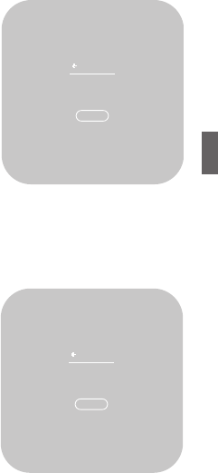
CYCLING
1. From the Home screen, press
and hold the SIDE button for
three (3) seconds.
2. Press DOWN to highlight
Installer, then press the SIDE
button.
3. Press DOWN to highlight
Comfort, then press the SIDE
button.
4. Press DOWN to highlight
Cycling, then press the SIDE
button. The current cycling value displays.
5. Press UP or DOWN to change the value, then press the SIDE
button to conrm.
Installer: Comfort Cont.
OFF TARGET
1.5°
HEAT/COOL
WHENEVER
-2°
CALIBRATION
OFFSET BY
40

Customization
Vivint Element CT200 Operation Guide
STAGING
1. From the Home screen, press
and hold the SIDE button for
three (3) seconds.
2. Press DOWN to highlight
Installer, then press the SIDE
button.
3. Press DOWN to highlight
Comfort, then press the SIDE
button.
4. Press DOWN to highlight
Staging, then press the SIDE
button. The current staging
value displays.
5. Press UP or DOWN to change the value, then press the SIDE
button to conrm.
NETWORK
Network settings enable you to link (connect) the Thermostat to a
Z-Wave Network, and to reset the network connection.
LINK
Before starting this procedure, go
to your Vivint panel and prepare
it for new devices. Once it is
ready, link the Thermostat to the
network.
1. From the Home screen, press
and hold the SIDE button for
three (3) seconds.
2. Press DOWN to highlight
Installer, then press the SIDE
button.
3. Press DOWN to highlight
Network, then press the SIDE
button.
4. Press DOWN to highlight Link, then press the SIDE button.
The current networking status displays.
OFF TARGET
3.5°
START STAGE
2 WHENEVER
Link
NETWORK
STATUS
Unlinked
41

Customization
6
Vivint Element CT200 Operation Guide
5. Highlight Link, then press the SIDE button. The unit attempts to
connect to a local Z-Wave Network.
RESET
The Network>Reset resets the
Thermostat's radio to unlink it
from its linked Z-Wave Controller.
Use this option before replacing
your Z-Wave Controller so that
your Thermostat can connect to
the new controller.
1. From the Home screen, press
and hold the SIDE button for
three (3) seconds.
2. Press DOWN to highlight
Installer, then press the SIDE
button.
3. Press DOWN to highlight Network, then press the SIDE button.
4. Press DOWN to highlight Reset, then press the SIDE button.
5. To conrm that you want to reset the connection, press DOWN to
highlight Reset, then press the SIDE button.The connection resets.
Testing
Testing options enable you to test the functionality of your heating
and cooling equipment’s connection to the Thermostat. For
instructions on running these tests, see page 20 in the Installation
Guide.
Installer: Network/Reset Cont.
Reset
RESET
Are you sure?
42
Customization
Vivint Element CT200 Operation Guide
Reset
The Reset menu enables you to restart the Thermostat, as well as to
reset the device to factory defaults.
RESTART
1. From the Home screen, press
and hold the SIDE button for
three (3) seconds.
2. Press DOWN to highlight
Installer, then press the SIDE
button.
3. Press DOWN to highlight Reset,
then press the SIDE button.
4. Press DOWN to highlight
Restart, then press the SIDE
button.
5. To conrm that you want to
restart the device, press DOWN to highlight Reset, then press the
SIDE button.
The device restarts.
RESET
1. From the Home screen, press
and hold the SIDE button for three
(3) seconds.
2. Press DOWN to highlight
Installer, then press the SIDE
button.
3. Press DOWN to highlight Reset,
then press the SIDE button.
4. Press DOWN to highlight Reset,
then press the SIDE button.
5. To conrm that you want
to reset the device to factory
defaults, press DOWN to highlight
Reset, then press the SIDE button.
The device resets itself and reboots. You will need to connect the
device to your Z-Wave Network and specify your system’s equipment
and settings. See the Installation Guide Setup section.
Restart
RESTART
Restart
thermostat
now?
Reset
RESET
Reset to
factory
defaults?
43
Customization
6
Vivint Element CT200 Operation Guide
Other Device Information
Low Battery Warning
The Thermostat displays this screen when the batteries are running
low on charge and should be replaced. This screen will only display
once per day the rst time the screen wakes.
1. Press the SIDE button to dismiss this warning.
2. Turn the thermostat mode to OFF (from heat or cool).
3. Replace the batteries.
4. Turn the thermostat mode back on to HEAT or COOL.
Your settings will be retained and the thermostat will automatically
reconnect to the Z-Wave Network.
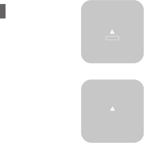
Network Disconnected
The Thermostat displays this
screen when it has lost its
connection to the Z-Wave
Network. This screen will only
display once per day the rst time
the screen wakes.
1. Press the SIDE button to
dismiss this warning.
2. Go to the Home > Installer
> Network > Link menu,
and follow the procedure to
reconnect the Thermostat to
the Z-Wave Network.
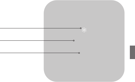
Firmware Updating
The Thermostat displays this
screen when it is updating its
rmware.
Wait until the rmware update is
complete (about 15 minutes) and
this screen is no longer displayed
before attempting to use the
Thermostat.
NETWORK
DISCONNECTED
OK
Updating
44

Vivint Element CT200 Operation Guide
FCC WARNING
Changes or modications to this unit not expressly approved by the
party responsible for compliance could void the user’s authority to
operate the equipment.
NOTE: This equipment has been tested and found to comply with
the limits for a Class B digital device, pursuant to Part 15 of the FCC
Rules. These limits are designed to provide reasonable protection
against harmful interference in a residential installation. This
equipment generates, uses and can radiate radio frequency energy
and, if not installed and used in accordance with the instructions,
may cause harmful interference to radio communications.
However, there is no guarantee that interference will not occur
in a particular installation. If this equipment does cause harmful
interference to radio or television reception (which can be
determined by turning the equipment o and on), try to correct the
interference by following these suggestions:
• Reorient or relocate the receiving antenna.
• Increase the separation between the equipment and receiver.
• Connect the equipment to an outlet on a circuit dierent from
that to which the receiver is connected.
• Consult the dealer or an experienced radio/TV technician for help.
45
WARNING: Changes or modifications to this receiver not expressly approved by RTCOA void
the user’s authority to operate this equipment.
RF Exposure info -- (manual)
This equipment complies with FCC’s and IC's RF radiation exposure limits set forth for an
uncontrolled environment. The antenna(s) used for this transmitter must be installed and
operated to provide a separation distance of at least 20 cm from all persons and must not be
collocated or operating in conjunction with any other antenna or transmitter. Installers must
ensure that 20cm separation distance will be maintained between the device (excluding its
handset) and users.

© 2015 Radio Thermostat Company of America. All rights reserved.
Statement Of Use
100% Compatible with all popular residential HVAC systems: 24VAC single stage
and two stage conventional heating systems (gas, oil, electric), heat pumps with
up to two stages of heat and up to two stages of auxiliary heat (electric or fossil),
zoned forced air and zoned hot water (2 or 3 wire), millivolt systems (with a 12-
24V AC or DC source), one or two stage cooling, and hybrid systems. Do not use
this thermostat with with line voltage heating systems.
RTCOA logo sheet
7aug07
This device complies with Industry Canada’s licence-exempt RSSs. Operation is subject to the following two conditions:
(1) This device may not cause interference; and
(2) This device must accept any interference, including interference that may cause undesired operation of the device.
Le présent appareil est conforme aux CNR d’Industrie Canada applicables aux appareils radio
exempts de licence. L’exploitation est autorisée aux deux conditions suivantes :
(1) l’appareil ne doit pas produire de brouillage;
(2) l’utilisateur de l’appareil doit accepter tout brouillage radioélectrique subi, même si le
brouillage est susceptible d’en compromettre le fonctionnement.