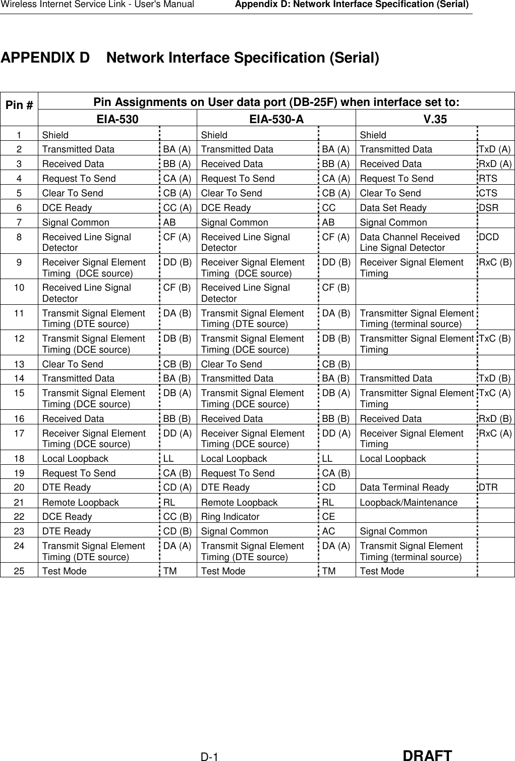
RadioConnect RCC0002-00 2.44 GHz RadioWire Modem User Manual
RadioConnect Corporation 2.44 GHz RadioWire Modem Users Manual
UserManual.wiki
>
RadioConnect
>
RCC0002 00 User Manual
Users Manual
Navigation menu
Upload a User Manual
Namespaces
Wiki Guide
HTML
PDF
Info
Views
User Manual
Discussion / Help
Navigation
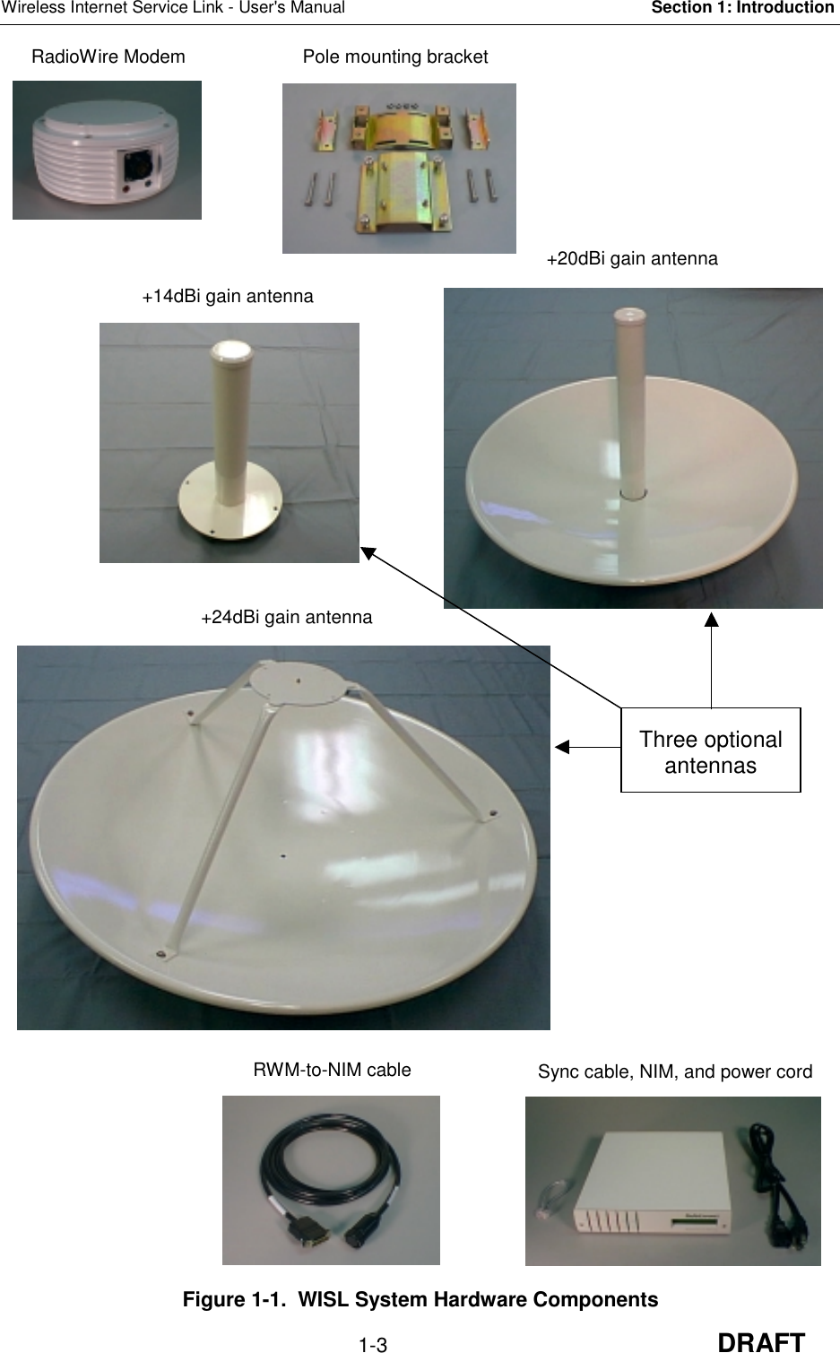
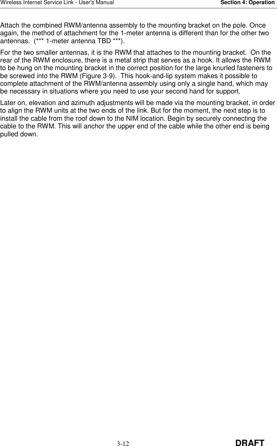
![DRAFTRadioWire®Wireless Internet Service LinkUser’s ManualRadioConnect Corporation3521 W. Lomita Blvd.,Suite 201Torrance, CA 90505Tel: (310) 891-2900Fax: (310) 891-2922Internet: http://www.radioconnect.com/P/N 950-0002-00Rev. [DRAFT] 3-22-99](https://usermanual.wiki/RadioConnect/RCC0002-00/User-Guide-30664-Page-3.png)

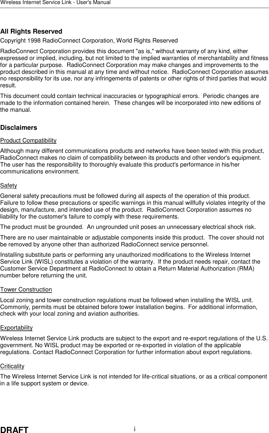
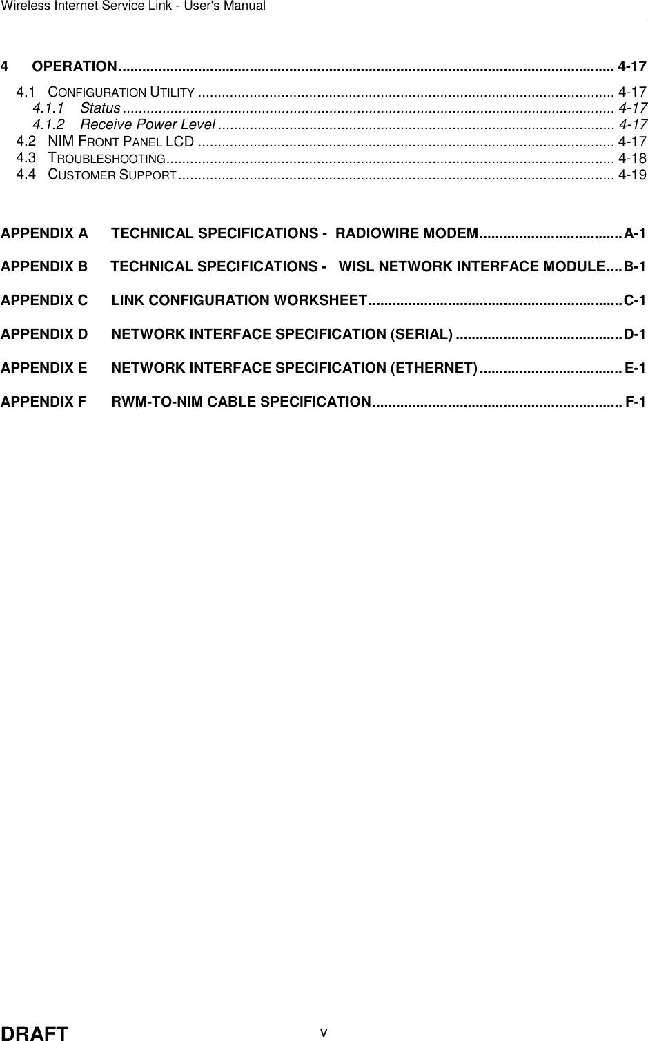
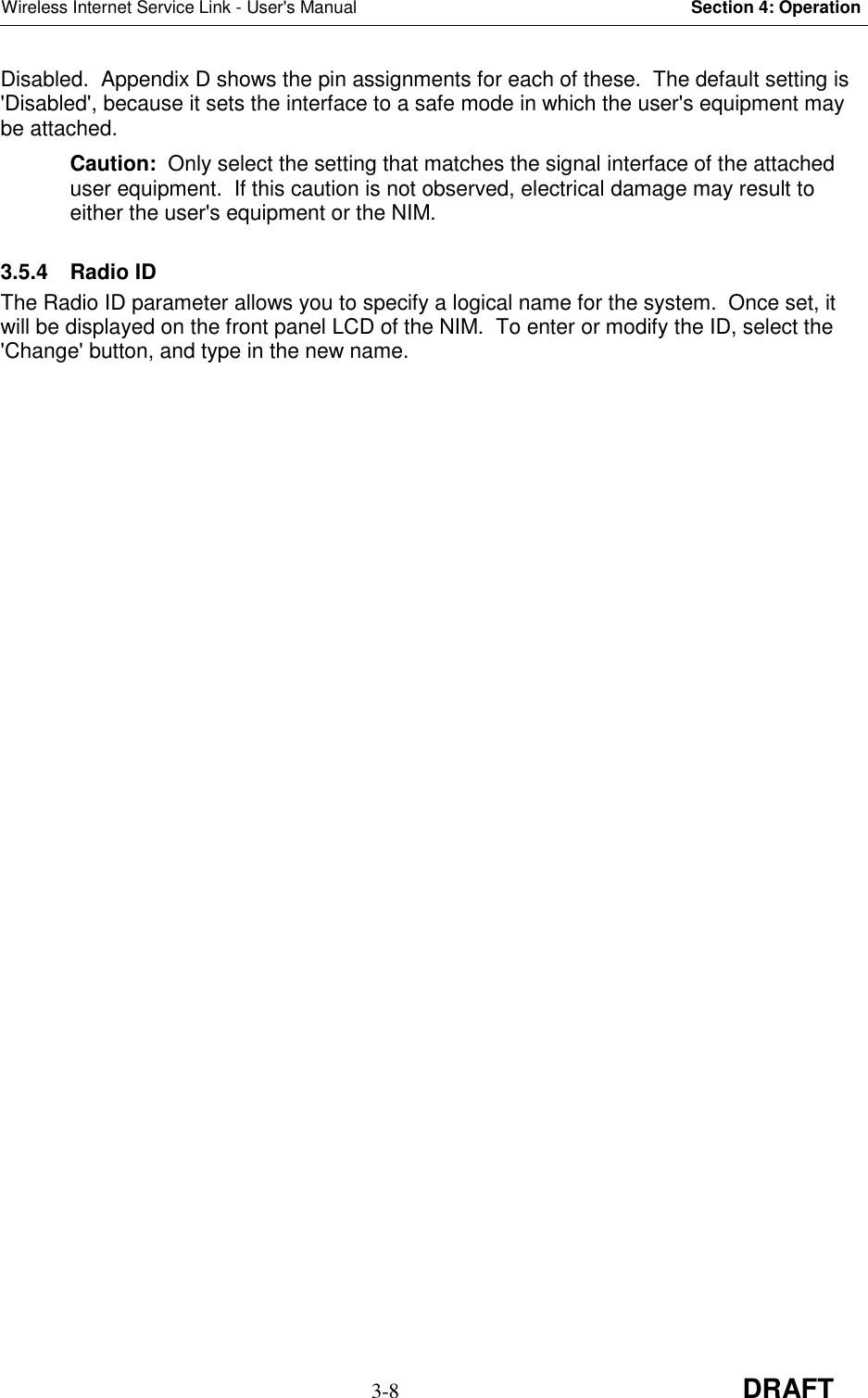
![Wireless Internet Service Link - User's Manual Section 2: System Description2-3 DRAFT Figure 2-3. Helical AntennaDimensions: Approx. 2.1 in [5.3 cm] diameter, 11 in [27.9 cm] lengthWeight: Less than 4.5 lbs. [2 kg.] (Antenna Only)Electrical Characteristics: 50 ohm; 1:1.3 VSWRGain pattern: 14 dBi, 35-degree beam width, right-hand or left-handcircularly polarized.Wind Survivability: 125 mph [200 km/h]Wind Load: 0.4 sq. ft. [0.04 sq. m]Part Numbers: Right-hand polarization (White Cap) 250-0001-00Left-hand polarization (Blue Cap) 250-0001-0128](https://usermanual.wiki/RadioConnect/RCC0002-00/User-Guide-30664-Page-15.png)
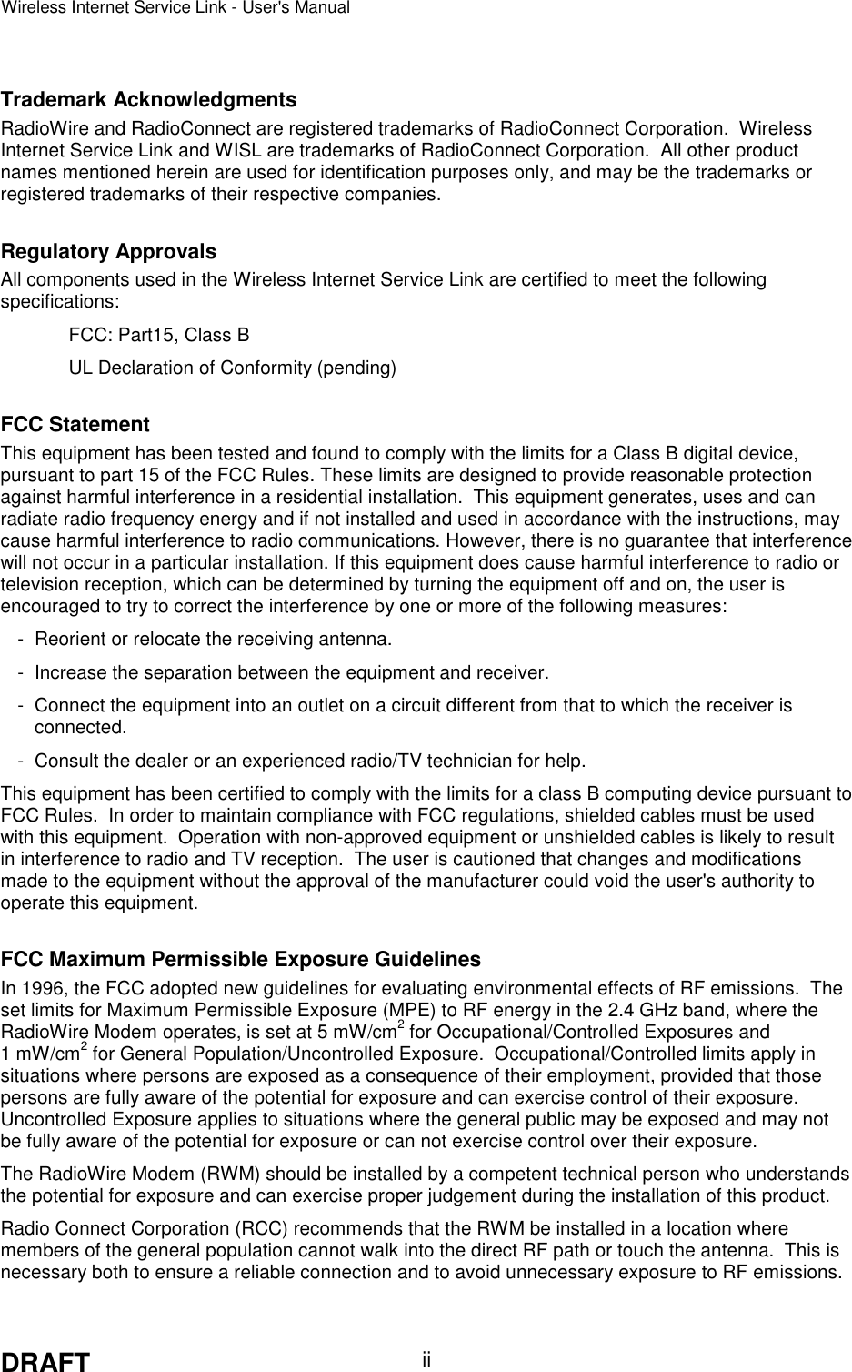
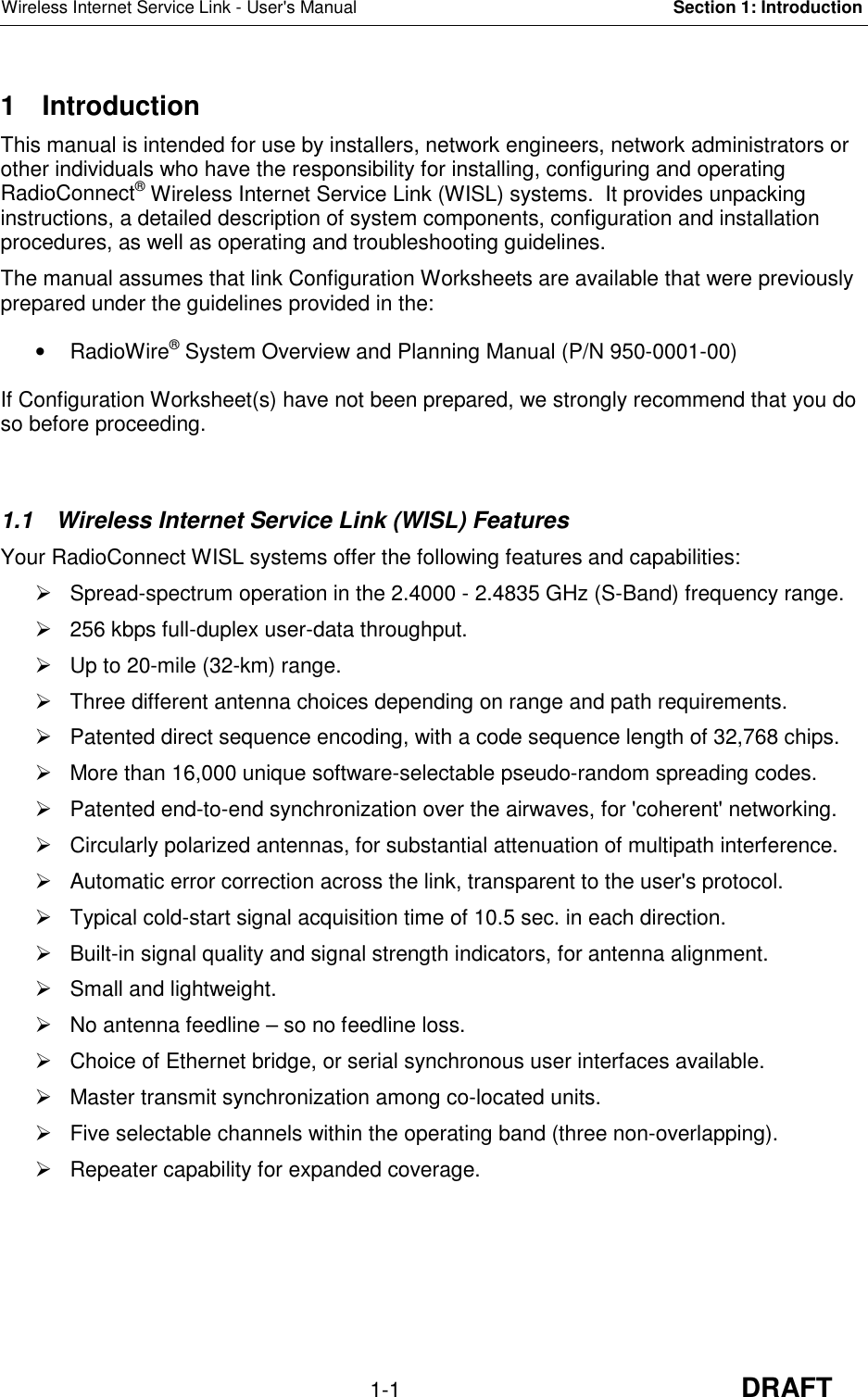
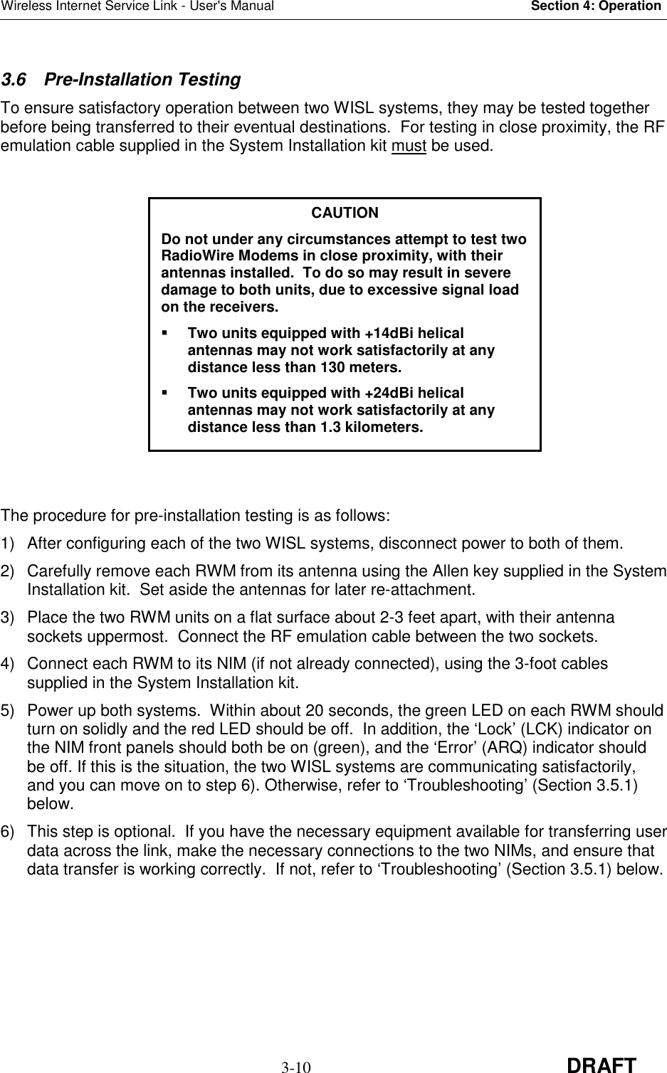
![Wireless Internet Service Link - User's Manual Section 2: System Description2-4 DRAFT Figure 2-4. 0.6 Meter Dish AntennaDimensions: Approx. 24 in [61 cm] diameter, 15 in [38.1 cm] lengthWeight: Less than 13.5 lbs. [6 kg.]Electrical Characteristics: 50 ohm; 1:1.3 VSWRGain pattern: 20 dBi, 15-degree beam width, right-hand or left-handcircularly polarized.Wind Survivability: 125 mph [200 km/h]Wind Load: 3.3 sq. ft. [0.3 sq. m]Part Numbers: Right-hand polarization (White Cap) 250-0002-00Left-hand polarization (Blue Cap) 250-0002-01](https://usermanual.wiki/RadioConnect/RCC0002-00/User-Guide-30664-Page-16.png)
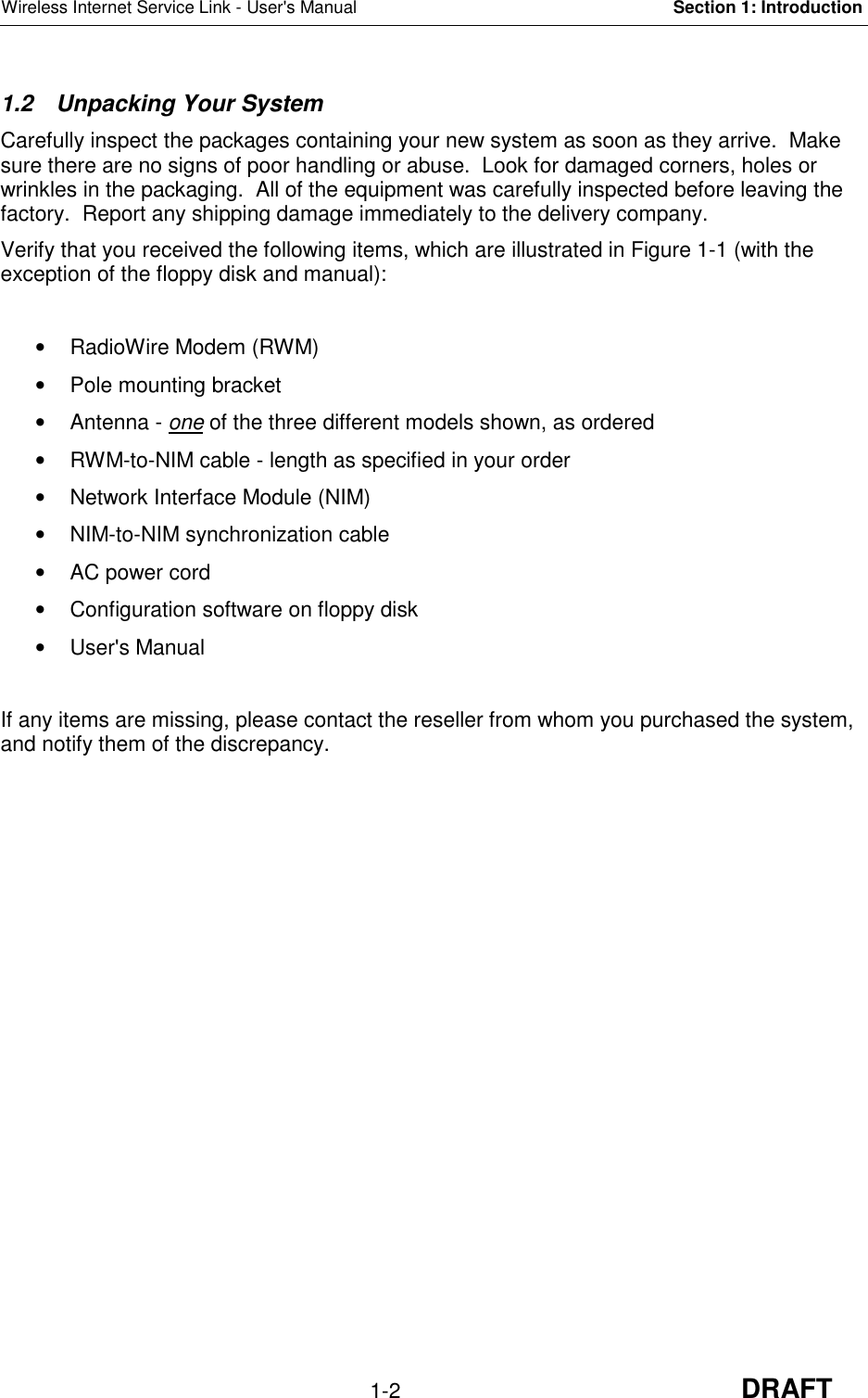
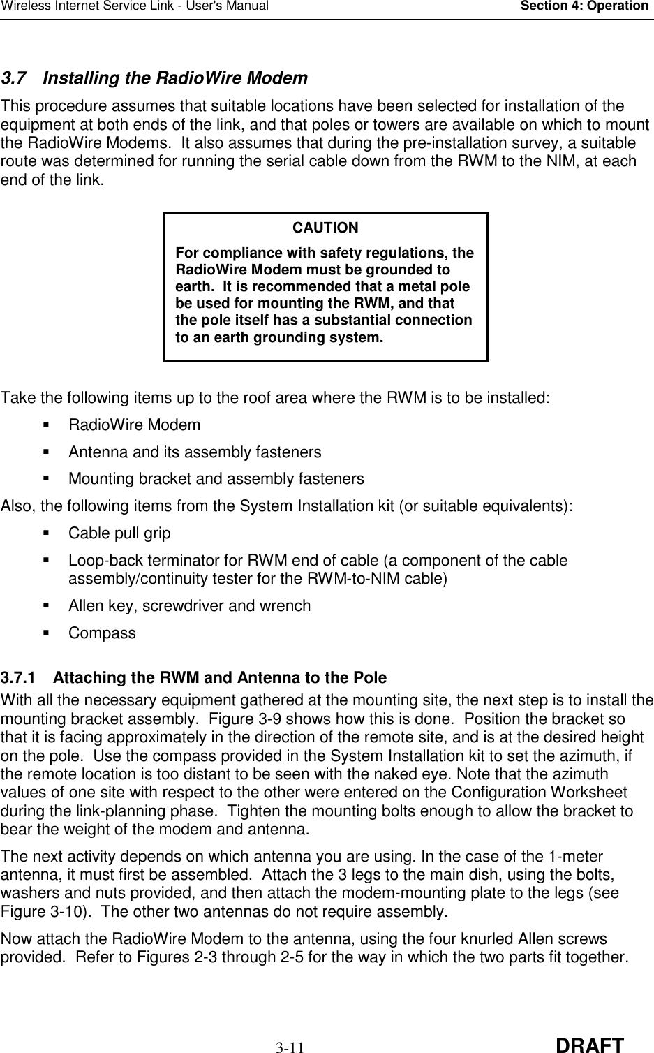
![Wireless Internet Service Link - User's Manual Section 2: System Description2-5 DRAFTFigure 2-5. 1.0 Meter Dish AntennaDimensions: Approx. 40 in [1 m] diameter, 18 in [45.7 cm] lengthWeight: Less than 20.5 lbs. [8 kg.]Electrical Characteristics: 50 ohm; 1:1.3 VSWRGain pattern: 24 dBi, 10-degree beam width, right-hand or left-handcircularly polarized.Wind Survivability: 125 mph [200 km/h]Wind Load: 35 sq. ft. [3.25 sq. m]Part Numbers: Right-hand polarization (White Cap) 250-0003-00Left-hand polarization (Blue Cap) 250-0003-01(46 cm)](https://usermanual.wiki/RadioConnect/RCC0002-00/User-Guide-30664-Page-17.png)
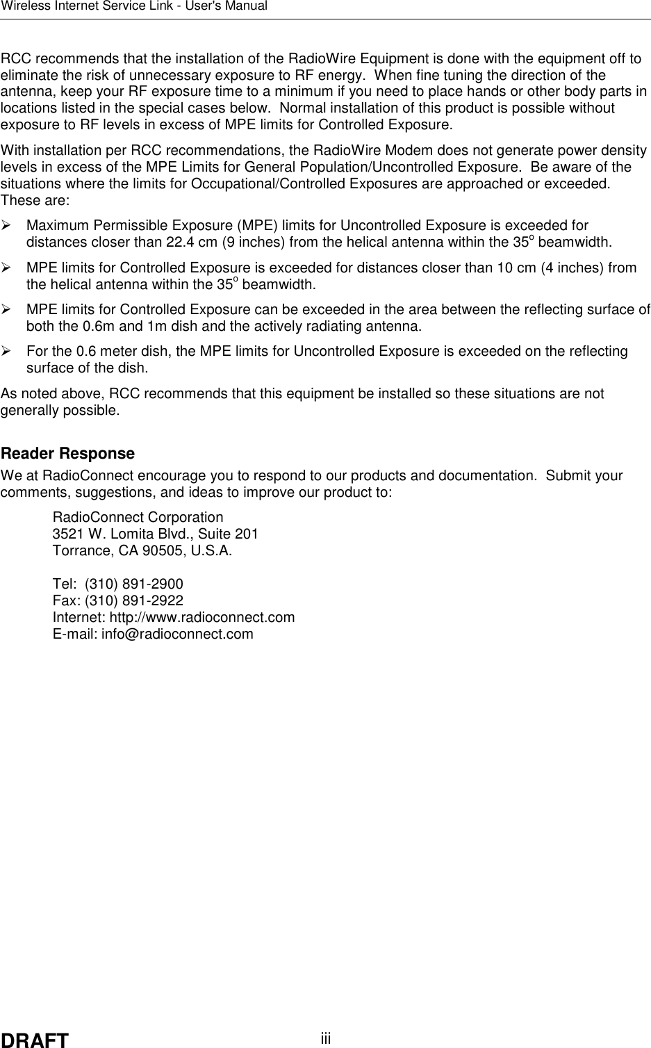
![Wireless Internet Service Link - User's Manual Section 4: Operation3-9 DRAFTLocation A Location BName (for ref. only) Headquarters Name (for ref. only) Branch 01Serial Number xxxxxxxxx Serial Number xxxxxxxxxLocation Culver City Location Long BeachLatitude 33 deg. 59 min. 10 sec. Latitude 33 deg. 45 min. 20 sec.Longitude 118 deg. 23 min. 20 sec. Longitude 118 deg. 11 min. 40 sec.Elevation of RWM 93 feet Elevation of RWM 57 feetDistance (A to B) 19.43 milesAzimuth of Loc. B 144.94 deg. Azimuth of Loc. A 324.94 deg.Heading to Loc. B deg Heading to Loc. A deg.Antenna Type(may be different atthe 2 locations)[] Helical[X] 0.6 m dish[] 1.0 m dishAntenna Type [] Helical[X] 0.6 m dish[] 1.0 m dishAnt. Cap Color [X] White [] Blue Ant. Cap Color Same as location AAntenna Angle inVertical Plane 0 deg. (horizontal) Antenna Angle inVertical Plane 0 deg. (horizontal)Pseudo-RandomSpreading Code #(0 - 16,383) 17 Pseudo-RandomSpreading Code #(0 - 16,383)Same as location AFreq. Channel [] CH1 (2,415.6MHz)[] CH2 (2,428.4 MHz)[X] CH3 (2,441.2 MHz)[] CH4 (2,454.0 MHz)[] CH5 (2,466.8 MHz)Freq. ChannelSame as location AMaster or Slave(one end must beMaster, other endmust be Slave)Master Master or Slave SlaveSync GeneratorStatus[] None [X] Primary[] Secondary[] TertiarySync GeneratorStatus[X] None [] Primary[] Secondary[] TertiaryTransmit Power(If manual, specifyvalue from +24 dBto –14 dB)[X] Auto [] Manual Transmit Power [X] Auto [] ManualFigure 3-8. Sample Configuration Worksheet (Complete)](https://usermanual.wiki/RadioConnect/RCC0002-00/User-Guide-30664-Page-29.png)
![Wireless Internet Service Link - User's ManualAppendix C: Link Configuration WorksheetC-1 DRAFTAPPENDIX C Link Configuration WorksheetLocation A Location BName (for ref. only) Name (for ref. only)Serial Number Serial NumberLocation LocationLatitude LatitudeLongitude LongitudeElevation of RWM Elevation of RWMDistance (A to B)Azimuth of Loc. B Azimuth of Loc. AAntenna Type(may be different atthe 2 locations)[] Helical[] 0.6 m dish[] 1.0 m dishAntenna Type [] Helical[] 0.6 m dish[] 1.0 m dishAnt. Cap Color [] White [] Blue Ant. Cap Color Same as location AAntenna Angle inVertical Plane Antenna Angle inVertical PlanePseudo-RandomSpreading Code #(0 - 16,383)Pseudo-RandomSpreading Code #(0 – 16,383)Same as location AFreq. Channel [] CH1 (2,415.6 MHz)[] CH2 (2,428.4 MHz)[] CH3 (2,441.2 MHz)[] CH4 (2,454.0 MHz)[] CH5 (2,466.8 MHz)Freq. ChannelSame as location AMaster or Slave(one end must beMaster, other endmust be Slave)Master or SlaveSync GeneratorStatus[] None [] Primary[] Secondary[] TertiarySync GeneratorStatus[] None [] Primary[] Secondary[] TertiaryTransmit Power(If manual, specifyvalue from +24 dBto –14 dB)[] Auto [] Manual Transmit Power [] Auto [] Manual](https://usermanual.wiki/RadioConnect/RCC0002-00/User-Guide-30664-Page-42.png)