RadioConnect RCC0002-00 2.44 GHz RadioWire Modem User Manual
RadioConnect Corporation 2.44 GHz RadioWire Modem Users Manual
Users Manual
DRAFT
Including:
♦ System Description
♦ Installation
♦ Operation
♦ Troubleshooting
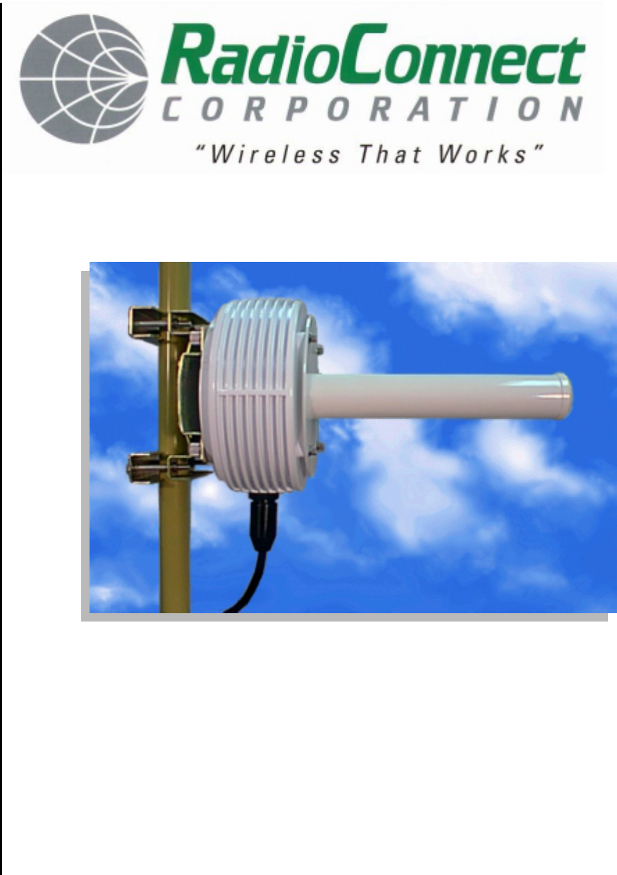
RadioWire
®
Wireless Internet Service Link
User’s Manual
DRAFT

DRAFT
RadioWire®
Wireless Internet Service Link
User’s Manual
RadioConnect Corporation
3521 W. Lomita Blvd.,
Suite 201
Torrance, CA 90505
Tel: (310) 891-2900
Fax: (310) 891-2922
Internet: http://www.radioconnect.com/
P/N 950-0002-00
Rev. [DRAFT] 3-22-99
DRAFT

Wireless Internet Service Link - User's Manual
DRAFT i
All Rights Reserved
Copyright 1998 RadioConnect Corporation, World Rights Reserved
RadioConnect Corporation provides this document "as is," without warranty of any kind, either
expressed or implied, including, but not limited to the implied warranties of merchantability and fitness
for a particular purpose. RadioConnect Corporation may make changes and improvements to the
product described in this manual at any time and without notice. RadioConnect Corporation assumes
no responsibility for its use, nor any infringements of patents or other rights of third parties that would
result.
This document could contain technical inaccuracies or typographical errors. Periodic changes are
made to the information contained herein. These changes will be incorporated into new editions of
the manual.
Disclaimers
Product Compatibility
Although many different communications products and networks have been tested with this product,
RadioConnect makes no claim of compatibility between its products and other vendor's equipment.
The user has the responsibility to thoroughly evaluate this product's performance in his/her
communications environment.
Safety
General safety precautions must be followed during all aspects of the operation of this product.
Failure to follow these precautions or specific warnings in this manual willfully violates integrity of the
design, manufacture, and intended use of the product. RadioConnect Corporation assumes no
liability for the customer's failure to comply with these requirements.
The product must be grounded. An ungrounded unit poses an unnecessary electrical shock risk.
There are no user maintainable or adjustable components inside this product. The cover should not
be removed by anyone other than authorized RadioConnect service personnel.
Installing substitute parts or performing any unauthorized modifications to the Wireless Internet
Service Link (WISL) constitutes a violation of the warranty. If the product needs repair, contact the
Customer Service Department at RadioConnect to obtain a Return Material Authorization (RMA)
number before returning the unit.
Tower Construction
Local zoning and tower construction regulations must be followed when installing the WISL unit.
Commonly, permits must be obtained before tower installation begins. For additional information,
check with your local zoning and aviation authorities.
Exportability
Wireless Internet Service Link products are subject to the export and re-export regulations of the U.S.
government. No WISL product may be exported or re-exported in violation of the applicable
regulations. Contact RadioConnect Corporation for further information about export regulations.
Criticality
The Wireless Internet Service Link is not intended for life-critical situations, or as a critical component
in a life support system or device.

Wireless Internet Service Link - User's Manual
DRAFT ii
Trademark Acknowledgments
RadioWire and RadioConnect are registered trademarks of RadioConnect Corporation. Wireless
Internet Service Link and WISL are trademarks of RadioConnect Corporation. All other product
names mentioned herein are used for identification purposes only, and may be the trademarks or
registered trademarks of their respective companies.
Regulatory Approvals
All components used in the Wireless Internet Service Link are certified to meet the following
specifications:
FCC: Part15, Class B
UL Declaration of Conformity (pending)
FCC Statement
This equipment has been tested and found to comply with the limits for a Class B digital device,
pursuant to part 15 of the FCC Rules. These limits are designed to provide reasonable protection
against harmful interference in a residential installation. This equipment generates, uses and can
radiate radio frequency energy and if not installed and used in accordance with the instructions, may
cause harmful interference to radio communications. However, there is no guarantee that interference
will not occur in a particular installation. If this equipment does cause harmful interference to radio or
television reception, which can be determined by turning the equipment off and on, the user is
encouraged to try to correct the interference by one or more of the following measures:
- Reorient or relocate the receiving antenna.
- Increase the separation between the equipment and receiver.
- Connect the equipment into an outlet on a circuit different from that to which the receiver is
connected.
- Consult the dealer or an experienced radio/TV technician for help.
This equipment has been certified to comply with the limits for a class B computing device pursuant to
FCC Rules. In order to maintain compliance with FCC regulations, shielded cables must be used
with this equipment. Operation with non-approved equipment or unshielded cables is likely to result
in interference to radio and TV reception. The user is cautioned that changes and modifications
made to the equipment without the approval of the manufacturer could void the user's authority to
operate this equipment.
FCC Maximum Permissible Exposure Guidelines
In 1996, the FCC adopted new guidelines for evaluating environmental effects of RF emissions. The
set limits for Maximum Permissible Exposure (MPE) to RF energy in the 2.4 GHz band, where the
RadioWire Modem operates, is set at 5 mW/cm2 for Occupational/Controlled Exposures and
1 mW/cm2 for General Population/Uncontrolled Exposure. Occupational/Controlled limits apply in
situations where persons are exposed as a consequence of their employment, provided that those
persons are fully aware of the potential for exposure and can exercise control of their exposure.
Uncontrolled Exposure applies to situations where the general public may be exposed and may not
be fully aware of the potential for exposure or can not exercise control over their exposure.
The RadioWire Modem (RWM) should be installed by a competent technical person who understands
the potential for exposure and can exercise proper judgement during the installation of this product.
Radio Connect Corporation (RCC) recommends that the RWM be installed in a location where
members of the general population cannot walk into the direct RF path or touch the antenna. This is
necessary both to ensure a reliable connection and to avoid unnecessary exposure to RF emissions.

Wireless Internet Service Link - User's Manual
DRAFT iii
RCC recommends that the installation of the RadioWire Equipment is done with the equipment off to
eliminate the risk of unnecessary exposure to RF energy. When fine tuning the direction of the
antenna, keep your RF exposure time to a minimum if you need to place hands or other body parts in
locations listed in the special cases below. Normal installation of this product is possible without
exposure to RF levels in excess of MPE limits for Controlled Exposure.
With installation per RCC recommendations, the RadioWire Modem does not generate power density
levels in excess of the MPE Limits for General Population/Uncontrolled Exposure. Be aware of the
situations where the limits for Occupational/Controlled Exposures are approached or exceeded.
These are:
Maximum Permissible Exposure (MPE) limits for Uncontrolled Exposure is exceeded for
distances closer than 22.4 cm (9 inches) from the helical antenna within the 35o beamwidth.
MPE limits for Controlled Exposure is exceeded for distances closer than 10 cm (4 inches) from
the helical antenna within the 35o beamwidth.
MPE limits for Controlled Exposure can be exceeded in the area between the reflecting surface of
both the 0.6m and 1m dish and the actively radiating antenna.
For the 0.6 meter dish, the MPE limits for Uncontrolled Exposure is exceeded on the reflecting
surface of the dish.
As noted above, RCC recommends that this equipment be installed so these situations are not
generally possible.
Reader Response
We at RadioConnect encourage you to respond to our products and documentation. Submit your
comments, suggestions, and ideas to improve our product to:
RadioConnect Corporation
3521 W. Lomita Blvd., Suite 201
Torrance, CA 90505, U.S.A.
Tel: (310) 891-2900
Fax: (310) 891-2922
Internet: http://www.radioconnect.com
E-mail: info@radioconnect.com

Wireless Internet Service Link - User's Manual
DRAFT iv
Table of Contents
All Rights Reserved..........................................................................................................................i
Disclaimers.......................................................................................................................................i
Trademark Acknowledgments ........................................................................................................ ii
Regulatory Approvals......................................................................................................................ii
FCC Statement ...............................................................................................................................ii
FCC Maximum Permissible Exposure Guidelines.......................................................................... ii
Reader Response .......................................................................................................................... iii
1 INTRODUCTION ........................................................................................................................ 1-1
1.1 WIRELESS INTERNET SERVICE LINK (WISL) FEATURES .............................................................. 1-1
1.2 UNPACKING YOUR SYSTEM........................................................................................................ 1-2
2 SYSTEM DESCRIPTION............................................................................................................ 2-1
2.1 RADIOWIRE MODEM.................................................................................................................. 2-1
2.1.1 Alignment Indicators........................................................................................................ 2-1
2.1.2 Antenna........................................................................................................................... 2-2
2.1.3 Mounting Bracket ............................................................................................................ 2-2
2.1.4 RWM-to-NIM Cable......................................................................................................... 2-2
2.2 NETWORK INTERFACE MODULE.................................................................................................. 2-6
2.2.1 Rear Panel Connectors................................................................................................... 2-6
2.2.2 Front Panel Display and Indicators................................................................................. 2-7
2.2.3 Synchronization Cable .................................................................................................... 2-8
3 INSTALLATION.......................................................................................................................... 3-1
3.1 SYSTEM INSTALLATION KIT ........................................................................................................ 3-1
3.2 INSTALLATION PROCEDURE........................................................................................................ 3-1
3.3 CONFIGURING YOUR SYSTEM .................................................................................................... 3-3
3.4 RADIO CONFIGURATION PARAMETERS........................................................................................ 3-5
3.4.1 Frequency Channel......................................................................................................... 3-5
3.4.2 Master/Slave Status........................................................................................................3-5
3.4.3 Synchronization Generator ............................................................................................. 3-6
3.4.4 Transmit Power Level ..................................................................................................... 3-6
3.4.5 Pseudo-Random Spreading Code.................................................................................. 3-7
3.5 NIM CONFIGURATION PARAMETERS........................................................................................... 3-7
3.5.1 Type ................................................................................................................................ 3-7
3.5.2 Clock Polarity (Serial only).............................................................................................. 3-7
3.5.3 User Mode (Serial only) .................................................................................................. 3-7
3.5.4 Radio ID .......................................................................................................................... 3-8
3.6 PRE-INSTALLATION TESTING .................................................................................................... 3-10
3.6.1 Troubleshooting ................................................................. Error! Bookmark not defined.
3.7 INSTALLING THE RADIOWIRE MODEM ....................................................................................... 3-11
3.7.1 Attaching the RWM and Antenna to the Pole ............................................................... 3-11
3.7.2 Cable Installation........................................................................................................... 3-14
3.8 INSTALLING THE NETWORK INTERFACE MODULE ....................................................................... 3-15
3.8.1 Electrical Requirements ................................................................................................ 3-16
3.9 ANTENNA ALIGNMENT PROCEDURE .......................................................................................... 3-16
3.10 CONNECTING TO USER’S EQUIPMENT................................................................................... 3-16

Wireless Internet Service Link - User's Manual
DRAFT v
4 OPERATION............................................................................................................................. 4-17
4.1 CONFIGURATION UTILITY ......................................................................................................... 4-17
4.1.1 Status ............................................................................................................................ 4-17
4.1.2 Receive Power Level .................................................................................................... 4-17
4.2 NIM FRONT PANEL LCD ......................................................................................................... 4-17
4.3 TROUBLESHOOTING................................................................................................................. 4-18
4.4 CUSTOMER SUPPORT.............................................................................................................. 4-19
APPENDIX A TECHNICAL SPECIFICATIONS - RADIOWIRE MODEM....................................A-1
APPENDIX B TECHNICAL SPECIFICATIONS - WISL NETWORK INTERFACE MODULE....B-1
APPENDIX C LINK CONFIGURATION WORKSHEET................................................................C-1
APPENDIX D NETWORK INTERFACE SPECIFICATION (SERIAL) ..........................................D-1
APPENDIX E NETWORK INTERFACE SPECIFICATION (ETHERNET)....................................E-1
APPENDIX F RWM-TO-NIM CABLE SPECIFICATION............................................................... F-1

Wireless Internet Service Link - User's Manual Section 1: Introduction
1-1 DRAFT
1 Introduction
This manual is intended for use by installers, network engineers, network administrators or
other individuals who have the responsibility for installing, configuring and operating
RadioConnect® Wireless Internet Service Link (WISL) systems. It provides unpacking
instructions, a detailed description of system components, configuration and installation
procedures, as well as operating and troubleshooting guidelines.
The manual assumes that link Configuration Worksheets are available that were previously
prepared under the guidelines provided in the:
• RadioWire® System Overview and Planning Manual (P/N 950-0001-00)
If Configuration Worksheet(s) have not been prepared, we strongly recommend that you do
so before proceeding.
1.1 Wireless Internet Service Link (WISL) Features
Your RadioConnect WISL systems offer the following features and capabilities:
Spread-spectrum operation in the 2.4000 - 2.4835 GHz (S-Band) frequency range.
256 kbps full-duplex user-data throughput.
Up to 20-mile (32-km) range.
Three different antenna choices depending on range and path requirements.
Patented direct sequence encoding, with a code sequence length of 32,768 chips.
More than 16,000 unique software-selectable pseudo-random spreading codes.
Patented end-to-end synchronization over the airwaves, for 'coherent' networking.
Circularly polarized antennas, for substantial attenuation of multipath interference.
Automatic error correction across the link, transparent to the user's protocol.
Typical cold-start signal acquisition time of 10.5 sec. in each direction.
Built-in signal quality and signal strength indicators, for antenna alignment.
Small and lightweight.
No antenna feedline – so no feedline loss.
Choice of Ethernet bridge, or serial synchronous user interfaces available.
Master transmit synchronization among co-located units.
Five selectable channels within the operating band (three non-overlapping).
Repeater capability for expanded coverage.

Wireless Internet Service Link - User's Manual Section 1: Introduction
1-2 DRAFT
1.2 Unpacking Your System
Carefully inspect the packages containing your new system as soon as they arrive. Make
sure there are no signs of poor handling or abuse. Look for damaged corners, holes or
wrinkles in the packaging. All of the equipment was carefully inspected before leaving the
factory. Report any shipping damage immediately to the delivery company.
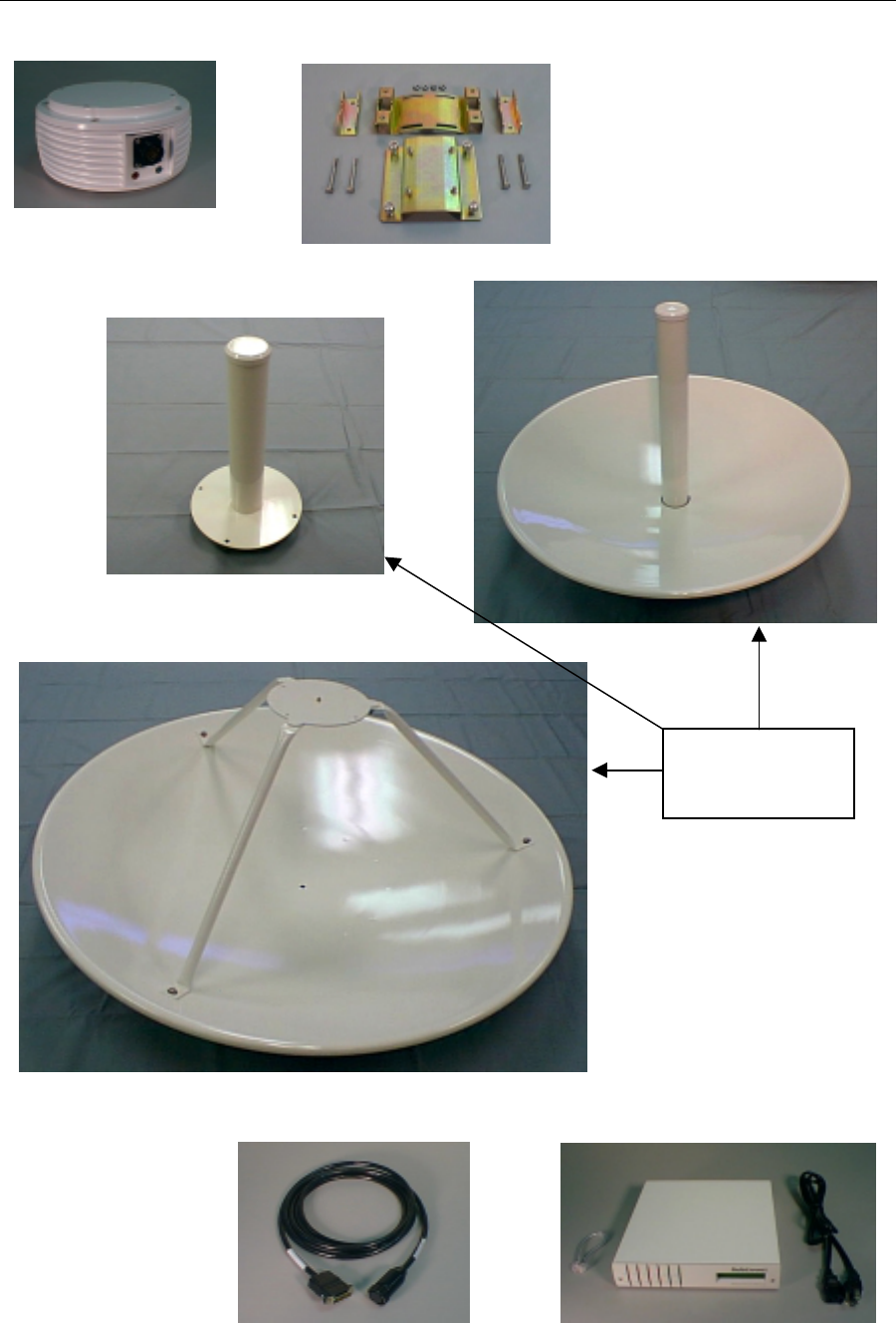
Verify that you received the following items, which are illustrated in Figure 1-1 (with the
exception of the floppy disk and manual):
• RadioWire Modem (RWM)
• Pole mounting bracket
• Antenna - one of the three different models shown, as ordered
• RWM-to-NIM cable - length as specified in your order
• Network Interface Module (NIM)
• NIM-to-NIM synchronization cable
• AC power cord
• Configuration software on floppy disk
• User's Manual
If any items are missing, please contact the reseller from whom you purchased the system,
and notify them of the discrepancy.
Wireless Internet Service Link - User's Manual Section 1: Introduction
1-3 DRAFT
Figure 1-1. WISL System Hardware Components
Pole mounting bracket
RWM-to-NIM cable Sync cable, NIM, and power cord
RadioWire Modem
+14dBi gain antenna
+20dBi gain antenna
+24dBi gain antenna
Three optional
antennas
Wireless Internet Service Link - User's Manual Section 2: System Description
2-1 DRAFT
2 System Description
2.1 RadioWire Modem
The RadioWire Modem is housed in a cast aluminum casing designed to withstand severe
weather conditions. It contains no parts that require user access, and should not be opened
by anyone except RadioConnect's authorized service personnel.
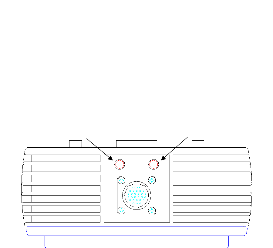
2.1.1 Alignment Indicators
Two alignment indicators are inset into the underside of the RWM case for ease of viewing
from a distance and in bright sunlight. These indicators are light emitting diodes (LEDs) -
one green, and one red:
Figure 2-1. Alignment Indicator LEDs
The indicator lights have the following functions:
Green = Received Signal Level/Acquisition
After signal acquisition, this green LED flashes at a rate proportional to the signal
level. Low signal levels will cause a slow blinking, while higher levels will cause the
blink rate to increase. At very high levels, the LED to appear to be on continuously.
Red = Packet error:
Indicates the occurrence of a link level error. The flash rate matches the rate at
which packet errors occur. Unless link error correction has been disabled, automatic
error correction is performed by the modem.
RedGreen
Wireless Internet Service Link - User's Manual Section 2: System Description
2-2 DRAFT
2.1.2 Antenna
Figures 2-3 through 2-5 provide details of the three antenna types available with the RWM.
It is not necessary to use the same type of antenna at the two ends of a link. The actual
combination depends on the range required. Table 2-1 shows the range capabilities of each
possible combination in free space conditions, assuming that a link margin of at least 25 dB
is pre-requisite. Note that the upper limit of 20 miles is governed by protocol constraints,
and not by the antenna gain.
Helical 0.6m dish 1.0m dish
Helical Range: 5 miles (8 km)
Link margin: 25.7 dB
0.6m dish Range: 10 miles (16 km)
Link margin: 25.7 dB Range: 20 miles (32 km)
Link margin: 25.7 dB
1.0m dish Range: 16 miles (26 km)
Link margin: 25.5 dB Range: 20 miles (32 km)
Link margin: 29.7 dB Range: 20 miles (32 km)
Link margin: 33.7 dB
Table 2-1. Range and Link Margin with Different Antenna Combinations
2.1.3 Mounting Bracket
RadioConnect antenna mounting brackets are designed to allow tilting in the vertical plane,
to accommodate elevation differences between the RWM units at the two ends of a link.
This capability is especially useful for relatively short links. The brackets are calibrated with
tilt angles above and below horizontal. Once the RadioWire Modems have been installed
and aligned with each other, and the brackets firmly locked in their optimum positions, you
should record the tilt angles read from the mounting brackets, in your Configuration
Worksheet.
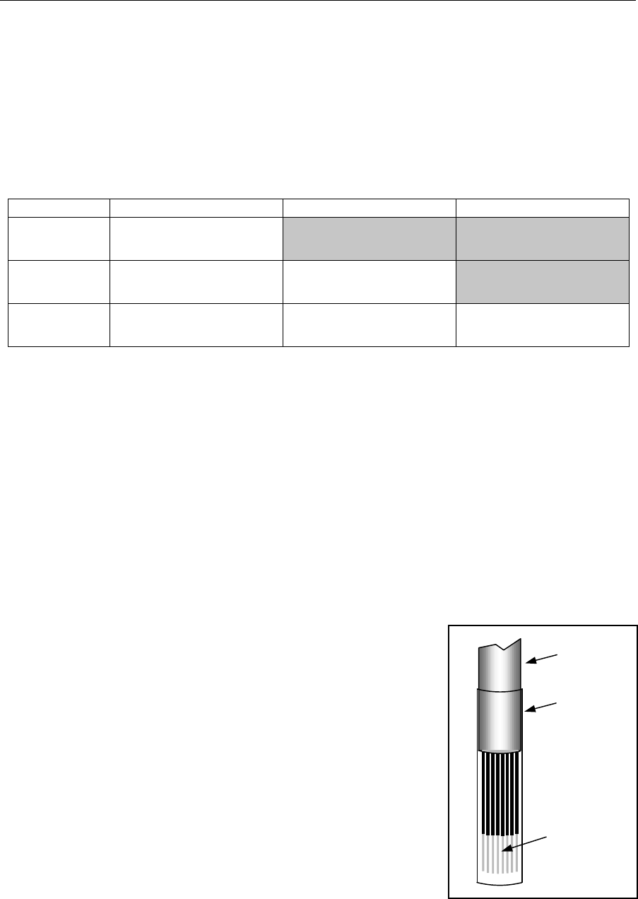
2.1.4 RWM-to-NIM Cable
The cable that runs between the roof-mounted RWM and the
in-building NIM is a special serial cable that carries low
voltage power up to the RWM, as well as carrying data
between the units. This cable is offered in standard lengths
from 25 feet to 200 feet, and in two different fire-resistance
ratings - standard or plenum-rated. Custom lengths are also
available to special order. Check that the lengths of the
cables you receive match your order, and if there is any
discrepancy, notify your reseller as soon as possible.
The standard PVC cable is satisfactory for use in vertical wall
cavities and shafts, while plenum-rated cable is required for
routing through under-floor plenum space. In either case, the
cable is supplied as a kit, with the connector not installed at
one end in order to facilitate feeding the cable between the
RWM and NIM. The connector for attachment to the RWM is
molded on to the cable, while the DB-25 for attachment to the
NIM is not installed. Instead, the open end of the cable has a
sleeve on it, as shown in Figure 2-2.
Cable
Pins for
insertion
into DB-25
connector
Protective
sleeve
Figure 2-2. NIM End of
Cable, as Shipped.
Wireless Internet Service Link - User's Manual Section 2: System Description
2-3 DRAFT
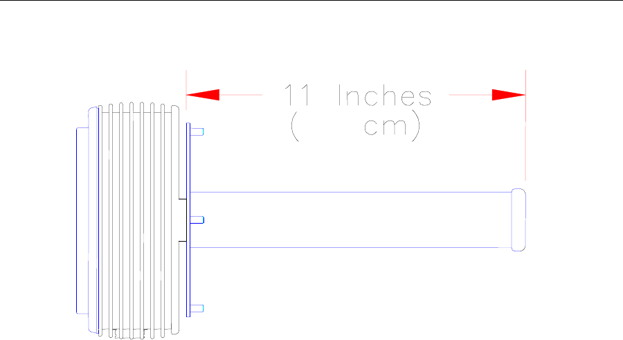
Figure 2-3. Helical Antenna
Dimensions: Approx. 2.1 in [5.3 cm] diameter, 11 in [27.9 cm] length
Weight: Less than 4.5 lbs. [2 kg.] (Antenna Only)
Electrical Characteristics: 50 ohm; 1:1.3 VSWR
Gain pattern: 14 dBi, 35-degree beam width, right-hand or left-hand
circularly polarized.
Wind Survivability: 125 mph [200 km/h]
Wind Load: 0.4 sq. ft. [0.04 sq. m]
Part Numbers: Right-hand polarization (White Cap) 250-0001-00
Left-hand polarization (Blue Cap) 250-0001-01
28
Wireless Internet Service Link - User's Manual Section 2: System Description
2-4 DRAFT
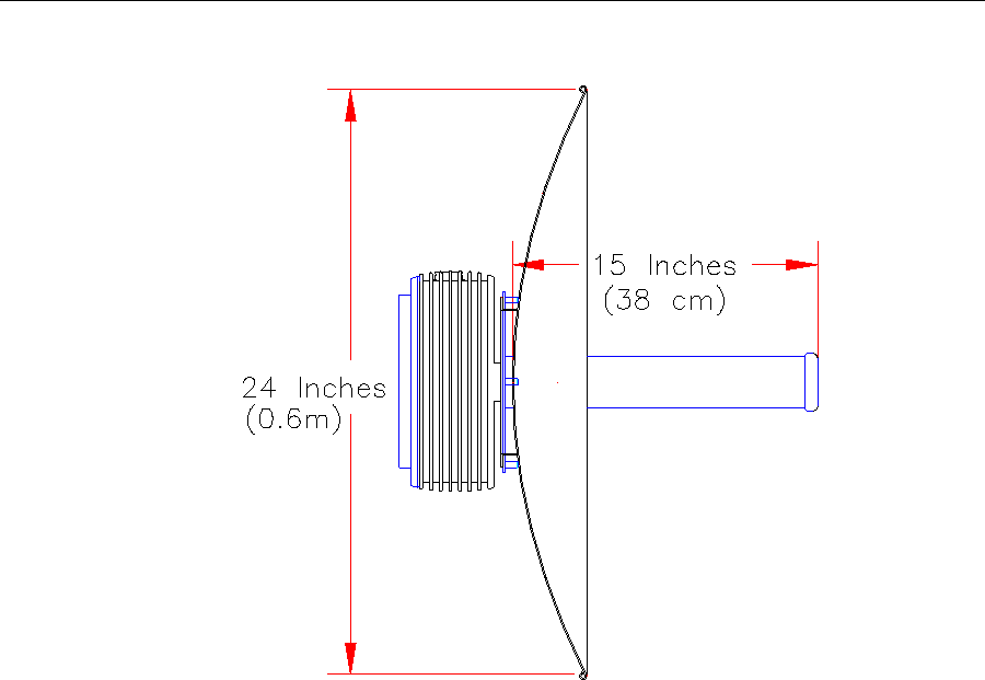
Figure 2-4. 0.6 Meter Dish Antenna
Dimensions: Approx. 24 in [61 cm] diameter, 15 in [38.1 cm] length
Weight: Less than 13.5 lbs. [6 kg.]
Electrical Characteristics: 50 ohm; 1:1.3 VSWR
Gain pattern: 20 dBi, 15-degree beam width, right-hand or left-hand
circularly polarized.
Wind Survivability: 125 mph [200 km/h]
Wind Load: 3.3 sq. ft. [0.3 sq. m]
Part Numbers: Right-hand polarization (White Cap) 250-0002-00
Left-hand polarization (Blue Cap) 250-0002-01
Wireless Internet Service Link - User's Manual Section 2: System Description
2-5 DRAFT
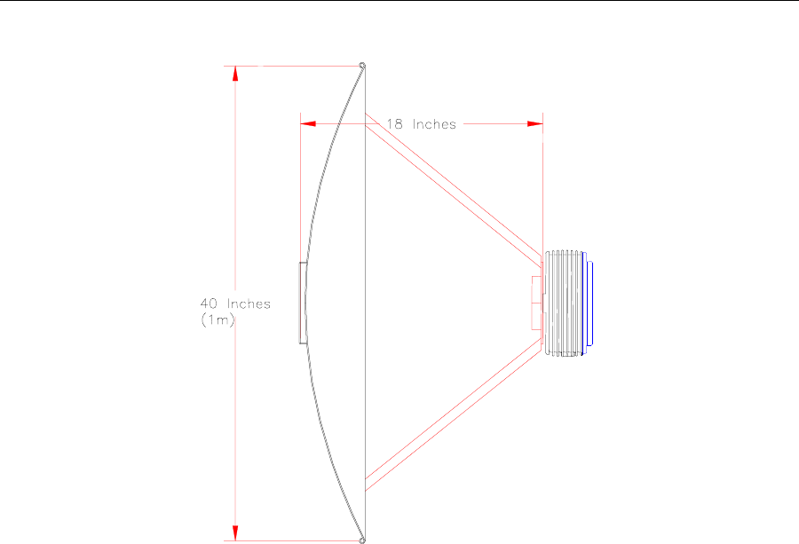
Figure 2-5. 1.0 Meter Dish Antenna
Dimensions: Approx. 40 in [1 m] diameter, 18 in [45.7 cm] length
Weight: Less than 20.5 lbs. [8 kg.]
Electrical Characteristics: 50 ohm; 1:1.3 VSWR
Gain pattern: 24 dBi, 10-degree beam width, right-hand or left-hand
circularly polarized.
Wind Survivability: 125 mph [200 km/h]
Wind Load: 35 sq. ft. [3.25 sq. m]
Part Numbers: Right-hand polarization (White Cap) 250-0003-00
Left-hand polarization (Blue Cap) 250-0003-01
(46 cm)
Wireless Internet Service Link - User's Manual Section 2: System Description
2-6 DRAFT
2.2 Network Interface Module
The Network Interface Module (NIM) provides the connection point between user equipment
and the WISL system. It may be installed as a stand-alone unit, or pairs of NIM units may
be coupled together side-by-side and mounted in a standard 19" rack. RadioConnect offers
a custom kit for this purpose (part number 250-0001-00). When installed in a rack, the NIM
units occupy 1U height.
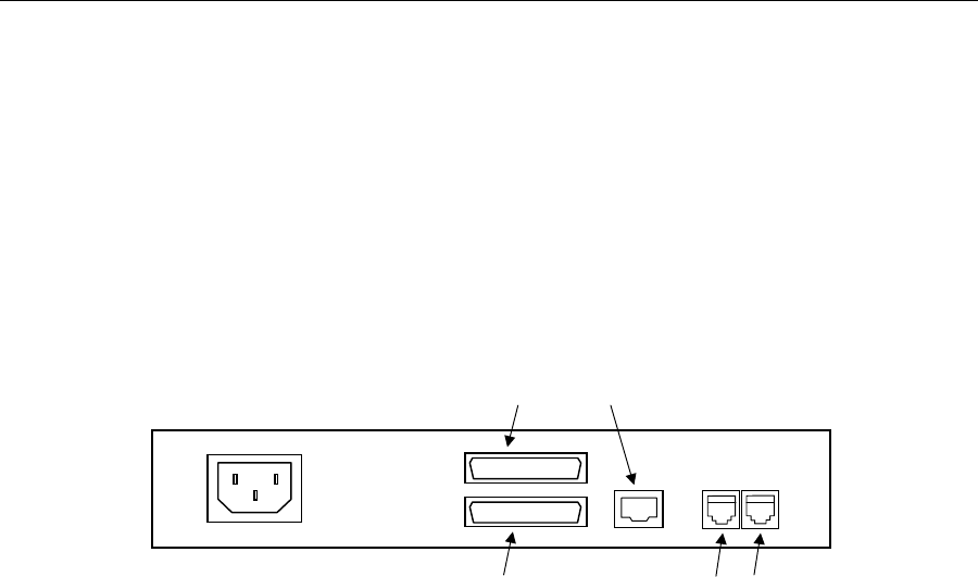
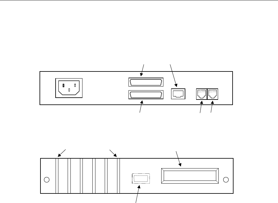
2.2.1 Rear Panel Connectors
Figure 2-6. Rear Panel
The NIM rear panel is illustrated in Figure 2-6. The following connectors are present on
both models of the NIM (serial or Ethernet):
AC Power: Standard IEC male connector.
100-240 VAC (auto-sensing), 47-63 Hz
RWM port: DB-25 female connector, for attachment of
RWM-to-NIM cable. See Appendix F for
signals and pinouts.
NIM-to-NIM ports: RJ-H connectors, for synchronization among
multiple co-located NIM units.
For the WISL system with serial interface, there is an additional connector:
Serial port: DB-25 female, for attachment to user equipment.
See Appendix D for EIA-530 signals and pinouts.
For connection to Cisco routers in the following
families, use Cisco cable CAB-530MT (part
number 72-0797-01): Cisco 7000 series,
4000 series, 3600 series, 2500 series,
1600 series, Cisco access servers, and
AccessPro cards.
For the WISL system with Ethernet interface, there is an additional connector:
Ethernet port: RJ-45, for attachment to user's 10BaseT LAN.
User-data port (DB-25F/EIA-530 or RJ-45/10BaseT)
Wireless Modem port (DB-25F) NIM-to-NIM sync ports
Wireless Internet Service Link - User's Manual Section 2: System Description
2-7 DRAFT
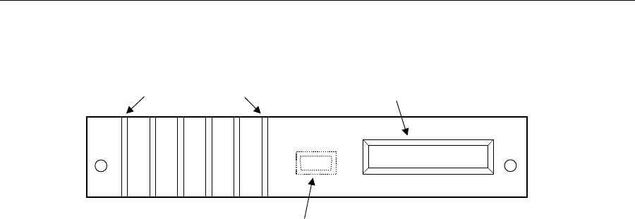
2.2.2 Front Panel Display and Indicators
Figure 2-7. Front Panel
Figure 2-7 shows the NIM front panel layout. The liquid crystal display (LCD) at the right
side of the panel displays ongoing status information, and is updated automatically at
1-second intervals.
At the left side of the panel, six light emitting diodes (LEDs) serve as signal indicators:
USER An active connection exists between the NIM and the user's
(Green LED) equipment. For the serial NIM, this implies that the cable
between the NIM and the user's equipment is installed, and
that the DTR (Data Terminal Ready) signal is asserted. For
the Ethernet NIM, the LED indicates that an active Ethernet
cable is connected to the NIM.
CL For the serial NIM, this LED indicates that the NIM clocking
(Red LED) signal is present. This is the signal that enables synchronous
transmission to occur. For the Ethernet NIM, this LED flashes
whenever a collision is detected.
TX This LED is on whenever the user's equipment is transmitting
(Yellow) data to the NIM.
RX This LED is on whenever the NIM is forwarding the data it has
(Yellow) received from the RWM, to the user's equipment.
ARQ The ARQ LED flashes at the receiving end of a link when a
(Red) packet error is detected.
LCK This LED has a dual function. It flashes red while the
(Red/Green) RadioWire modems at the two ends of the link are attempting
to synchronize with one another. Once synchronized, the LED
changes to a solid green display, indicating that the two ends
are locked.
For initial configuration or re-configuration of the WISL system, the front panel of the NIM
unit may be removed to provide access to the Console port. The port comprises a female
DE-9 connector, to which either a PC-compatible computer or a dumb terminal may be
attached. The cable required is a 9-pin straight-through male-to-female serial cable. A
6-foot cable of this type is included in the System Installation Kit available separately from
RadioConnect (part number 004-0001-00). Such cables are also readily available at most
computer stores.
Signal indicators Status display
Console port (DE-9F) - remove front panel for access
USER CL TX RX ARQ LCK
Wireless Internet Service Link - User's Manual Section 2: System Description
2-8 DRAFT
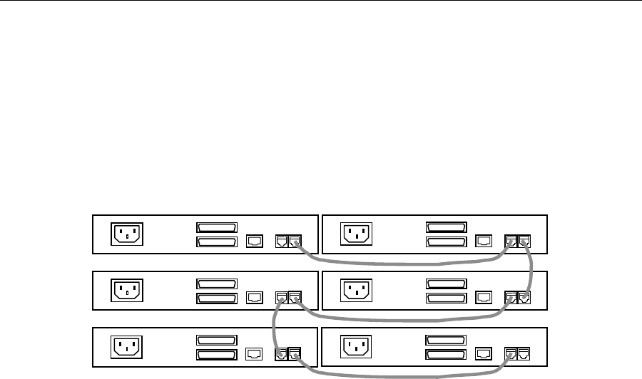
2.2.3 Synchronization Cable
One synchronization cable is provided with each WISL system. This 12" cable is used to
connect two NIM units together via the sync ports (RJ-H connectors) on the rear panel. More
than two NIMs may be interconnected by daisy-chaining them together, as shown in
Figure 2-8. Note that the two connectors on each unit are functionally identical, so that
either cable may be plugged into either socket.
Figure 2-8. NIM Units 'Daisy-Chained' for Synchronization
The purpose of interconnecting units in this way is to provide a clock signal between them
that causes all units to synchronize their transmit and receive cycles. The clock signal is
provided by a single NIM configured as the 'primary' unit. The effect of this interconnection
is that all units transmit in the same cycle, and then receive in the same cycle, which avoids
the possibility of some of the co-located units receiving the transmissions of others.

Wireless Internet Service Link - User's Manual Section 4: Operation
3-1 DRAFT
3 Installation
3.1 System Installation Kit
RadioConnect offers a System Installation Kit (part number 004-0001-00) which may be
purchased separately from your WISL systems. Although not pre-requisite for installing a
link, the kit is recommended. It is re-usable for installing multiple links, and contains the
following items:
3-foot RWM-to-NIM cable, required if units are to be configured prior to installation
6-foot Console cable
RF emulation cable
Cable pull grip
Cable assembly/continuity tester for RWM-to-NIM cable (comprises 2 components
– loop-back terminator for RWM end of cable, and display terminator for NIM end.)
Tools: Allen key, screwdriver and wrench
Magnetic compass
In addition to these items, the person installing the link may also need a steel-tape cable
puller (also referred to as a "snake"), and some nylon cable ties. A cable tie will be used to
attach the cable pull grip to the cable puller, as explained in Section 3.6.1 below.
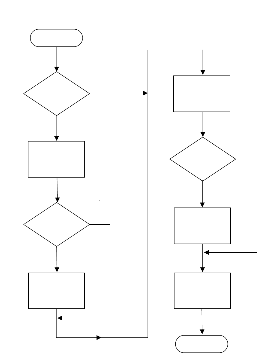
3.2 Installation Procedure
Figure 3-1 shows a high level flowchart of the required and optional steps for installing a
link. The WISL equipment can be installed without requiring initial configuration. However,
this is not recommended, as it is much easier to configure and test both units together at a
single location, before they are transferred to their eventual (remote) sites.
In either case, at least one configuration parameter must be set before the two WISL
systems can communicate. That parameter is the ‘Master/Slave Status’ (Section 3.4.3). Until
one end of the link is set as Master, and the other end as Slave, installed units cannot be
aligned.
CAUTION
If you are not familiar with working on towers and antennas,
get help from an experienced installer. Installing tower
structures and mounting antennas can be dangerous and
life threatening. Make sure the tower or pole you are using
is of appropriate size to carry the weight and wind load of
the RadioWire Modem and antenna system.
Wireless Internet Service Link - User's Manual Section 4: Operation
3-2 DRAFT
Figure 3-1. Installation Procedure
Configure
units before
installation?
Test systems
before
installation?
Are systems
configured as
desired?
Set up and
configure both
systems.
Install RF
emulation cable,
and check link
operation is OK.
Transfer systems
to their remote
locations and
install them.
Configure each of
the two systems,
then align them
using built-in LEDs
Connect user
equipment at each
end of link, and
test data transfer.
Start
Installation
complete
Yes
Yes
Yes
No
No
No

Wireless Internet Service Link - User's Manual Section 4: Operation
3-3 DRAFT
3.3 Configuring Your System
The first step towards configuring each of your WISL systems is to complete the link
Configuration Worksheet (Appendix C). Refer to the System Overview and Planning Manual
(part number 950-0001-00) for guidance in preparing the Worksheet. There are several
important parameters that must be configured correctly for proper operation:
1) Pseudo-random spreading code
2) Frequency channel
3) Master/Slave status
4) Synchronization generator status
5) Transmit power control mode and level
Each of these parameters is discussed in detail below, and a completed Worksheet example
is shown in Figure 3-8.
Next, take the following steps in preparation for configuring each unit:
If the configuration process is being carried out before a WISL system has been
installed, connect the RWM and NIM together using the 3-foot cable provided in the
System Installation Kit.
If the configuration process is being carried out after installation, the RWM and NIM are
already connected.
Connect a personal computer (PC) to the NIM console port (section 2.2.2) using a
standard serial cable (9-pin, straight through, male-to-female). One such cable is
provided in the System Installation kit.
Power up the PC and install the Configuration Utility from the 2-disk set provided with
your WISL system. The PC must be running Windows 95 or later, or Windows NT.
Insert disk 1 into the floppy drive, and display its contents under Windows Explorer.
Double click on the file 'setup.exe', then simply follow the on-screen instructions to
complete the installation.
Power up the NIM, then load the Configuration Utility by double clicking its icon. The
following window will open:
Figure 3-2. Configuration Utility - Port Selection Screen
Select the COM port to which the NIM is attached, then click the 'Continue' button.
Wireless Internet Service Link - User's Manual Section 4: Operation
3-4 DRAFT
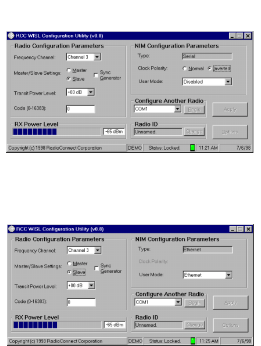
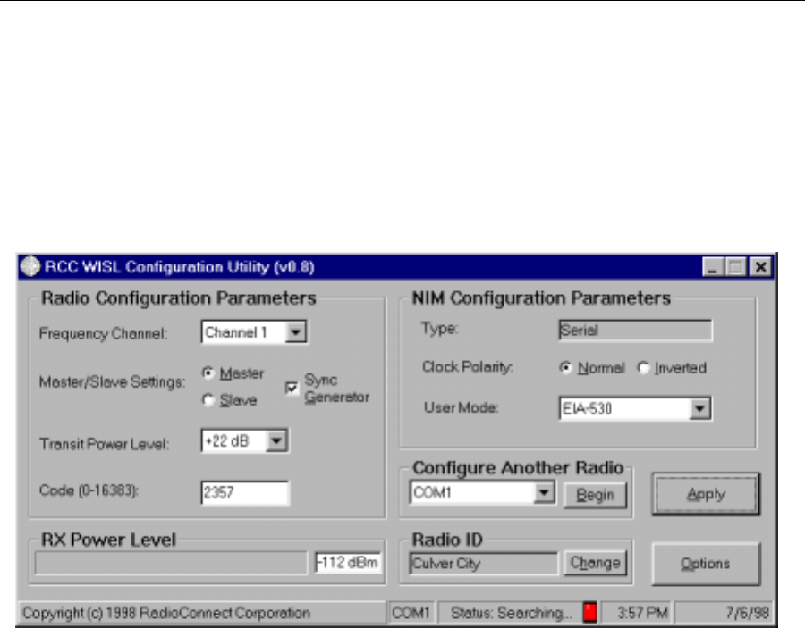
The main window of the Configuration Utility will now open:
Figure 3-3. Configuration Utility - Main Window for Serial NIM
This window provides both configuration management and operational information. The
items displayed in the window will vary according to the type of NIM. Figure 3-3 shows the
main window for a serial NIM with default settings displayed, while figure 3-4 is for an
Ethernet NIM:
Figure 3-4. Configuration Utility - Main Window for Ethernet NIM
Wireless Internet Service Link - User's Manual Section 4: Operation
3-5 DRAFT
3.4 Radio Configuration Parameters
3.4.1 Frequency Channel
The RadioWire Modem supports three discrete, non-overlapping frequency channels within
the 2.4 GHz band allocated for unlicensed use. These are shown in the Configuration
Worksheet as channels 1, 3 and 5. The other two channels (2 and 4) partially overlap their
neighbors. In general, use channels 1, 3 or 5 only, unless you are co-locating more than
three RWM units at the same site. Select the desired channel from the pull-down menu.
3.4.2 Master/Slave Status
One unit on each point-to-point link must be configured as the link Master. The other unit
must be the link Slave. The link Master controls transmit and receive timing for a given link.
When multiple RWM units are co-located, they will typically all be specified as Masters
(Figure 3-5). However, if a hierarchical network is being built, similar to that shown in
Figure 3-6, all nodes except the central one will have at least one Slave coupled to one or
more subsidiary Masters through appropriate user equipment such as an Ethernet hub or a
serial synchronous time-division multiplexer (TDM). Click on the appropriate button to select
Master or Slave status.
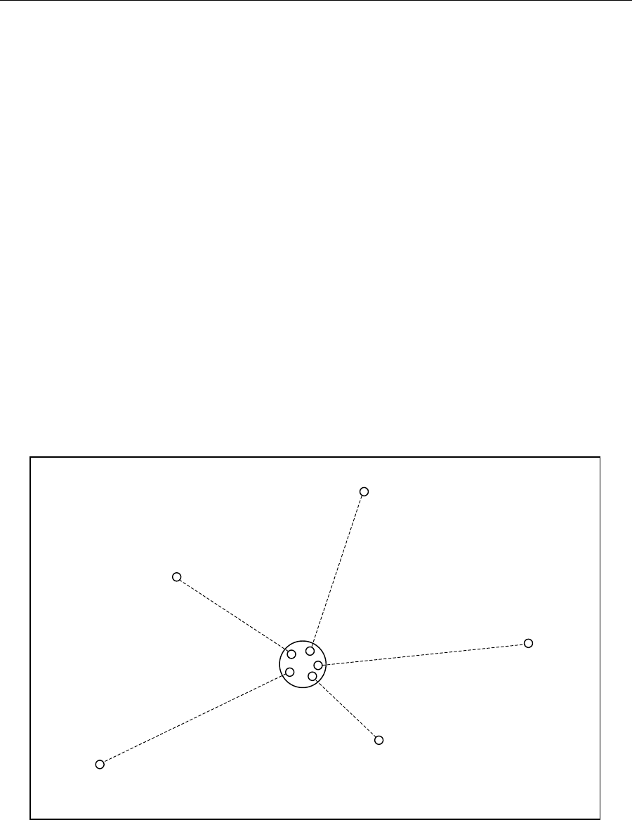
Figure 3-5. Master/Slave Assignments in a Star Network
A
ll central units
are ‘Masters’
‘Slave’
‘Slave’
‘Slave’
‘Slave’
‘Slave’
Wireless Internet Service Link - User's Manual Section 4: Operation
3-6 DRAFT
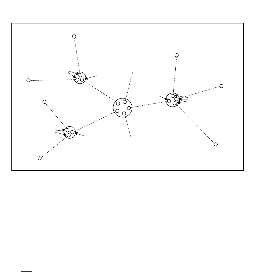
Figure 3-6. Master/Slave Assignments in a Hierarchical Network
3.4.3 Synchronization Generator
When multiple RWMs are co-located at a site, they must be synchronized to all transmit at
the same time and all receive at the same time, to help avoid mutual interference. To
accomplish this, every RWM is equipped with the ability to generate a synchronous clock
signal. However, only one unit can be the active synchronization generator at any given
time, and all other co-located units must receive the synchronization signal through the
‘daisy-chain’ of cables that couple their NIMs together.
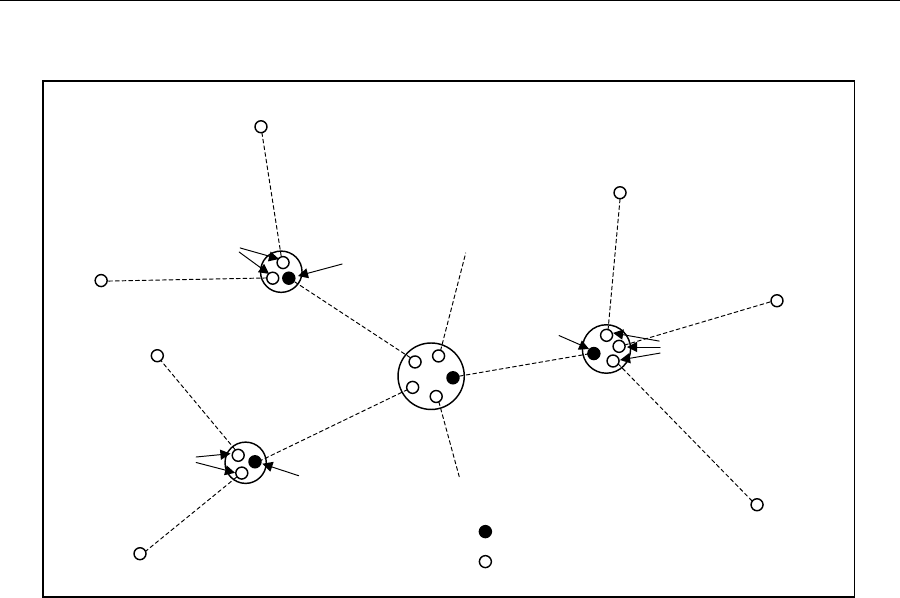
A special requirement applies at all subsidiary nodes of a hierarchical network. At all such
nodes, only Slave units may take the role of synchronization generators. This is because a
Slave unit derives its clock from the airwave signal it receives from its associated Master.
This requirement ensures that the entire network operates coherently from a single clock
source. The example in Figure 3-7 illustrates this. Click on Sync Generator, if required.
3.4.4 Transmit Power Level
The transmit power level may be set between a minimum of -2dB and a maximum of +24dB.
When shipped, the default setting is 0dB. If a unit is being configured prior to installation,
care should be taken with regard to increasing the power level. Excessive power levels can
be hazardous to humans, as well as to other operating radio equipment in the near vicinity.
If possible, setting of the power level should be left until the link is being installed. In the
U.S.A., the maximum power level of +24dB is only required when operating at the maximum
range specified for the antennas. Some countries require a lower maximum transmit power
level than the +24dB permitted in the U.S.A.
A
ll central units
are ‘Masters’
‘Slave’
‘Slave’
‘Slave’
‘Slave’
‘Masters’
‘Slave’
‘Slave’
‘Masters’
‘Slave’
‘Slave’
‘Masters’
‘Slave’
‘Slave’
Wireless Internet Service Link - User's Manual Section 4: Operation
3-7 DRAFT
Figure 3-7. Synchronization Generators in a Hierarchical Network
3.4.5 Pseudo-Random Spreading Code
There are more than 16,000 possible pseudo-random spreading codes available to ensure
the privacy of RadioWire links, and which contribute towards the extraordinary interference
rejection characteristics of RWM units. The same value must be configured for both ends of
a link. If multiple links are to be installed, select a different code for each link.
Many RWMs can share the same frequency channel with negligible interference when a
different pseudo-random code is selected for each different link.
3.5 NIM Configuration Parameters
3.5.1 Type
By default, this field will display the type of NIM being configured - Serial or Ethernet - and
may not be altered.
3.5.2 Clock Polarity (Serial only)
This parameter must match the clock polarity of the equipment attached to the NIM. The
default setting is 'Normal'. If necessary, click on 'Inverted'.
3.5.3 User Mode (Serial only)
The connector on the Serial NIM for attachment of user equipment is a female DB-25.
However, the User Mode parameter allows you to select the active signal interface on the
connector. The choices available on the pull-down menu are V.35, EIA-530, EIA-530A or
A
ll central units
are ‘Masters’
‘Slave’
‘Slave’
‘Slave’
‘Slave’
‘Masters’
‘Slave’
‘Slave’
‘Masters’
‘Slave’
‘Slave’
‘Masters’
‘Slave’
‘Slave’
= Sync generator
= Not sync generator

Wireless Internet Service Link - User's Manual Section 4: Operation
3-8 DRAFT
Disabled. Appendix D shows the pin assignments for each of these. The default setting is
'Disabled', because it sets the interface to a safe mode in which the user's equipment may
be attached.
Caution: Only select the setting that matches the signal interface of the attached
user equipment. If this caution is not observed, electrical damage may result to
either the user's equipment or the NIM.
3.5.4 Radio ID
The Radio ID parameter allows you to specify a logical name for the system. Once set, it
will be displayed on the front panel LCD of the NIM. To enter or modify the ID, select the
'Change' button, and type in the new name.

Wireless Internet Service Link - User's Manual Section 4: Operation
3-9 DRAFT
Location A Location B
Name (for ref. only) Headquarters Name (for ref. only) Branch 01
Serial Number xxxxxxxxx Serial Number xxxxxxxxx
Location Culver City Location Long Beach
Latitude 33 deg. 59 min. 10 sec. Latitude 33 deg. 45 min. 20 sec.
Longitude 118 deg. 23 min. 20 sec. Longitude 118 deg. 11 min. 40 sec.
Elevation of RWM 93 feet Elevation of RWM 57 feet
Distance (A to B) 19.43 miles
Azimuth of Loc. B 144.94 deg. Azimuth of Loc. A 324.94 deg.
Heading to Loc. B deg Heading to Loc. A deg.
Antenna Type
(may be different at
the 2 locations)
[] Helical
[X] 0.6 m dish
[] 1.0 m dish
Antenna Type [] Helical
[X] 0.6 m dish
[] 1.0 m dish
Ant. Cap Color [X] White [] Blue Ant. Cap Color Same as location A
Antenna Angle in
Vertical Plane 0 deg. (horizontal) Antenna Angle in
Vertical Plane 0 deg. (horizontal)
Pseudo-Random
Spreading Code #
(0 - 16,383) 17 Pseudo-Random
Spreading Code #
(0 - 16,383)
Same as location A
Freq. Channel [] CH1 (2,415.6MHz)
[] CH2 (2,428.4 MHz)
[X] CH3 (2,441.2 MHz)
[] CH4 (2,454.0 MHz)
[] CH5 (2,466.8 MHz)
Freq. Channel
Same as location A
Master or Slave
(one end must be
Master, other end
must be Slave)
Master Master or Slave Slave
Sync Generator
Status
[] None [X] Primary
[] Secondary
[] Tertiary
Sync Generator
Status
[X] None [] Primary
[] Secondary
[] Tertiary
Transmit Power
(If manual, specify
value from +24 dB
to –14 dB)
[X] Auto [] Manual Transmit Power [X] Auto [] Manual
Figure 3-8. Sample Configuration Worksheet (Complete)

Wireless Internet Service Link - User's Manual Section 4: Operation
3-10 DRAFT
3.6 Pre-Installation Testing
To ensure satisfactory operation between two WISL systems, they may be tested together
before being transferred to their eventual destinations. For testing in close proximity, the RF
emulation cable supplied in the System Installation kit must be used.
The procedure for pre-installation testing is as follows:
1) After configuring each of the two WISL systems, disconnect power to both of them.
2) Carefully remove each RWM from its antenna using the Allen key supplied in the System
Installation kit. Set aside the antennas for later re-attachment.
3) Place the two RWM units on a flat surface about 2-3 feet apart, with their antenna
sockets uppermost. Connect the RF emulation cable between the two sockets.
4) Connect each RWM to its NIM (if not already connected), using the 3-foot cables
supplied in the System Installation kit.
5) Power up both systems. Within about 20 seconds, the green LED on each RWM should
turn on solidly and the red LED should be off. In addition, the ‘Lock’ (LCK) indicator on
the NIM front panels should both be on (green), and the ‘Error’ (ARQ) indicator should
be off. If this is the situation, the two WISL systems are communicating satisfactorily,
and you can move on to step 6). Otherwise, refer to ‘Troubleshooting’ (Section 3.5.1)
below.
6) This step is optional. If you have the necessary equipment available for transferring user
data across the link, make the necessary connections to the two NIMs, and ensure that
data transfer is working correctly. If not, refer to ‘Troubleshooting’ (Section 3.5.1) below.
CAUTION
Do not under any circumstances attempt to test two
RadioWire Modems in close proximity, with their
antennas installed. To do so may result in severe
damage to both units, due to excessive signal load
on the receivers.
Two units equipped with +14dBi helical
antennas may not work satisfactorily at any
distance less than 130 meters.
Two units equipped with +24dBi helical
antennas may not work satisfactorily at any
distance less than 1.3 kilometers.

Wireless Internet Service Link - User's Manual Section 4: Operation
3-11 DRAFT
3.7 Installing the RadioWire Modem
This procedure assumes that suitable locations have been selected for installation of the
equipment at both ends of the link, and that poles or towers are available on which to mount
the RadioWire Modems. It also assumes that during the pre-installation survey, a suitable
route was determined for running the serial cable down from the RWM to the NIM, at each
end of the link.
Take the following items up to the roof area where the RWM is to be installed:
RadioWire Modem
Antenna and its assembly fasteners
Mounting bracket and assembly fasteners
Also, the following items from the System Installation kit (or suitable equivalents):
Cable pull grip
Loop-back terminator for RWM end of cable (a component of the cable
assembly/continuity tester for the RWM-to-NIM cable)
Allen key, screwdriver and wrench
Compass
3.7.1 Attaching the RWM and Antenna to the Pole
With all the necessary equipment gathered at the mounting site, the next step is to install the
mounting bracket assembly. Figure 3-9 shows how this is done. Position the bracket so
that it is facing approximately in the direction of the remote site, and is at the desired height
on the pole. Use the compass provided in the System Installation kit to set the azimuth, if
the remote location is too distant to be seen with the naked eye. Note that the azimuth
values of one site with respect to the other were entered on the Configuration Worksheet
during the link-planning phase. Tighten the mounting bolts enough to allow the bracket to
bear the weight of the modem and antenna.
The next activity depends on which antenna you are using. In the case of the 1-meter
antenna, it must first be assembled. Attach the 3 legs to the main dish, using the bolts,
washers and nuts provided, and then attach the modem-mounting plate to the legs (see
Figure 3-10). The other two antennas do not require assembly.
Now attach the RadioWire Modem to the antenna, using the four knurled Allen screws
provided. Refer to Figures 2-3 through 2-5 for the way in which the two parts fit together.
CAUTION
For compliance with safety regulations, the
RadioWire Modem must be grounded to
earth. It is recommended that a metal pole
be used for mounting the RWM, and that
the pole itself has a substantial connection
to an earth grounding system.

Wireless Internet Service Link - User's Manual Section 4: Operation
3-12 DRAFT
Attach the combined RWM/antenna assembly to the mounting bracket on the pole. Once
again, the method of attachment for the 1-meter antenna is different than for the other two
antennas. (*** 1-meter antenna TBD ***).
For the two smaller antennas, it is the RWM that attaches to the mounting bracket. On the
rear of the RWM enclosure, there is a metal strip that serves as a hook. It allows the RWM
to be hung on the mounting bracket in the correct position for the large knurled fasteners to
be screwed into the RWM (Figure 3-9). This hook-and-lip system makes it possible to
complete attachment of the RWM/antenna assembly using only a single hand, which may
be necessary in situations where you need to use your second hand for support.
Later on, elevation and azimuth adjustments will be made via the mounting bracket, in order
to align the RWM units at the two ends of the link. But for the moment, the next step is to
install the cable from the roof down to the NIM location. Begin by securely connecting the
cable to the RWM. This will anchor the upper end of the cable while the other end is being
pulled down.
Wireless Internet Service Link - User's Manual Section 4: Operation
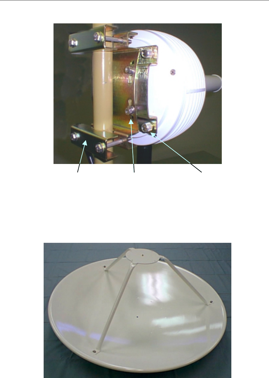
3-13 DRAFT
Mounting Bracket and
Azimuth Adjustment
(7/16" Bolts and Washers)
Vertical Tilt Adjustment
(7/16" Nuts and Washers) RWM Mounting
Fasteners
Figure 3-9. RWM Mounting Bracket
Figure 3-10. 1-meter Antenna
Wireless Internet Service Link - User's Manual Section 4: Operation
3-14 DRAFT
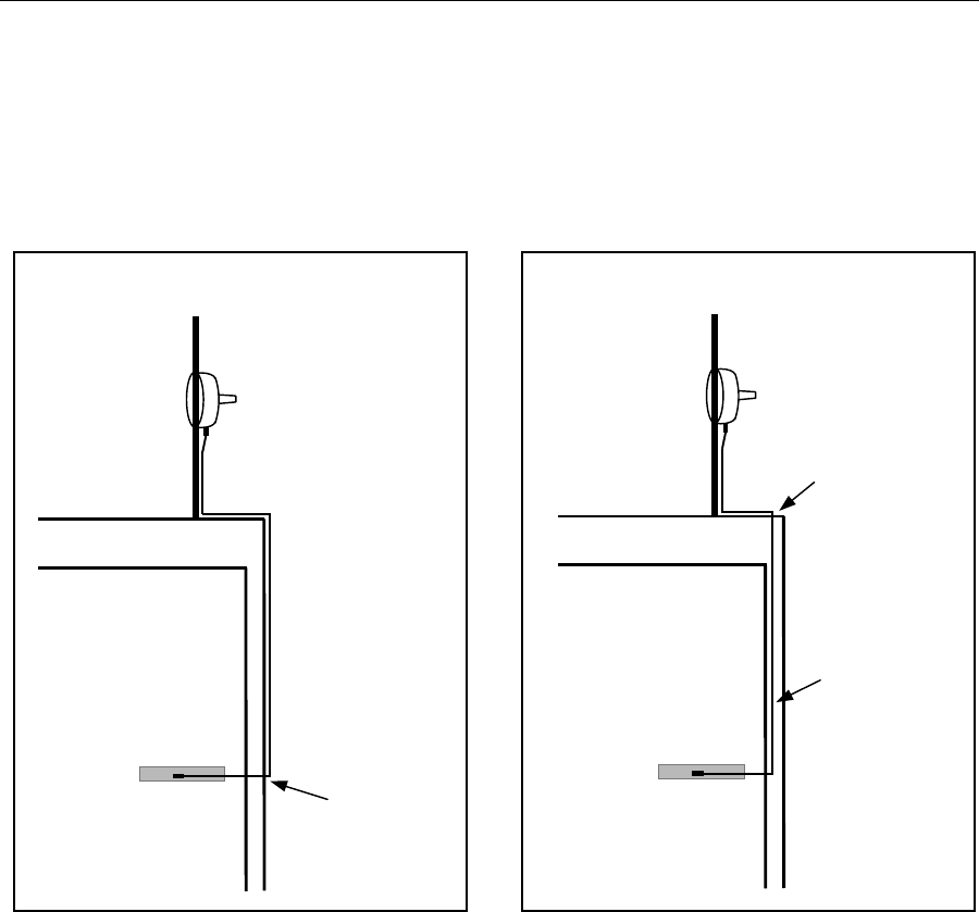
3.7.2 Cable Installation
At this point, you must determine whether a cable puller tool will be needed. For example, if
the cable will be run external to the building walls, the tool will probably not be needed
(Figure 3-11). Similarly, if a clear vertical path is available within the wall cavity, the cable
can be installed without the need for a puller.
However, cable routing is typically not as straightforward as shown here. Often, obstacles
within the wall cavities must be circumvented, or the cable must travel through a
combination of wall and floor cavities. In these cases, use a cable puller, starting from the
NIM location and working the steel tape up to the roof.
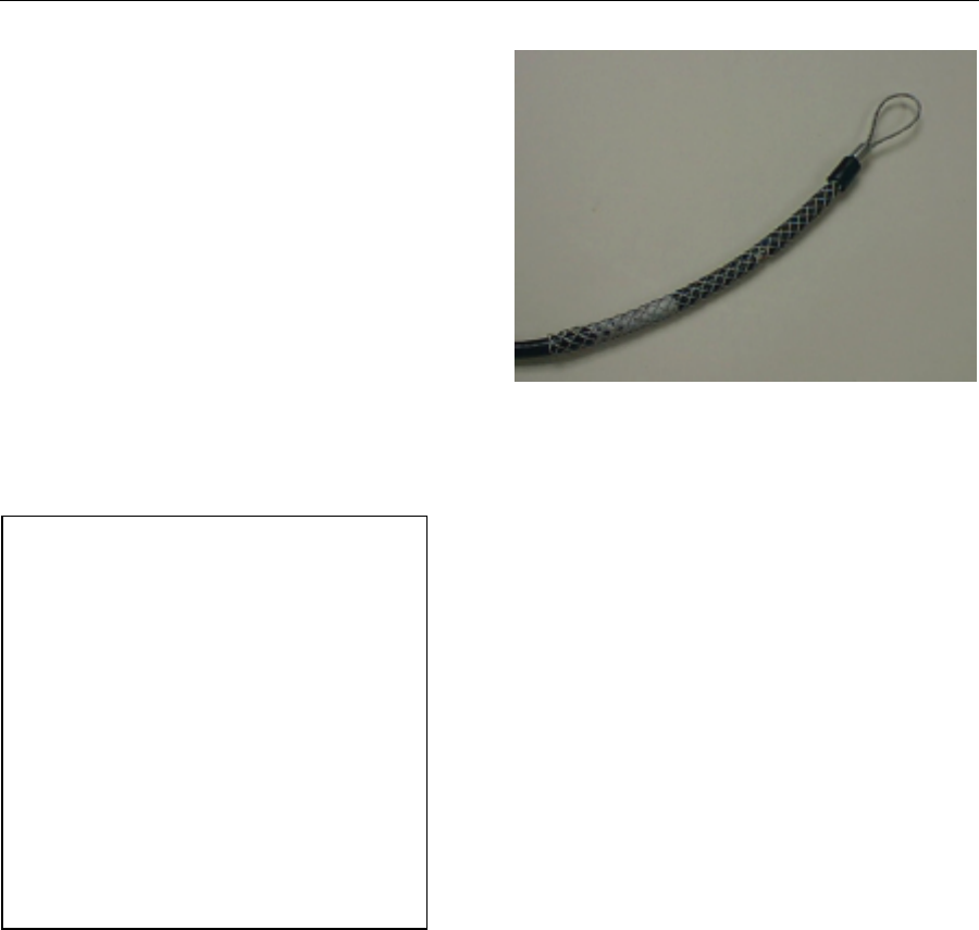
Next, return to the roof, and slide the cable pull grip fully over the open end of the cable,
ensuring that no slippage occurs once the grip is in place (Figure 3-12). Now connect the
loops at the ends of the cable pull grip and the steel tape, using a nylon tie wrap threaded
through them both. Trim the free end of the tie wrap, so that it will not catch on anything as
it passes through wall and/or floor cavities.
Return to the NIM location, and proceed to carefully reel-in the steel tape until the cable
reaches you. During this procedure, it may be useful or necessary to have the assistance of
a second person on the roof to feed the cable, ensuring that it does not get tangled.
You are now ready to install the DB-25 connector on the NIM end of the cable. Remove the
cable pull grip from the cable end, by pushing it off from its open end. This compresses the
mesh, thus releasing its friction grip on the cable and allowing it to slide off.
RadioWire Modem
Network Interface
Module
Roof
Cable entry
through wall
Pole
RadioWire Modem
Network Interface
Module
Roof
Cable entry
through roof
Pole
Cable routed
in wall cavity
Figure 3-11. Internal and External Cable Routing
Wireless Internet Service Link - User's Manual Section 4: Operation
3-15 DRAFT
Separate the two halves of the DB-25
connector shell and remove the main body
(see Figure 3-13). Using the pin-out
information provided in Appendix F,
carefully insert the pins into the numbered
holes, from the rear of the main body.
Ensure that all pins are fully seated and
protrude from the connector an equal
amount. Clamp the two shell halves back
over the cable and main body assembly,
ensuring that the braided grounding sheath
of the cable makes full contact with the
shell halves at the cable-entry collar. Insert
and tighten the screw that holds the two
halves together.
At this point you may optionally test the
complete cable for correct assembly and lead
continuity, using the tester provided in the
System Installation kit. To do so, go up to the
roof, disconnect the cable from the RWM, and
install the loop-back terminator on the cable
connector. Return to the NIM location and
install the display terminator component of the
tester.
(**** Add tester operating procedure ****)
After removing the test terminators, reconnect
the cable to the RWM.
3.8 Installing the Network Interface Module
The Network Interface Module must be located in the vicinity of the user equipment to which
it will be connected. It may either be installed as a freestanding unit on a suitable surface
such as a shelf, or a pair of NIM units may be attached side-by-side and rack-mounted in a
standard 19" rack. A special RadioConnect Universal Rack-Mount kit (Figure 3-14) is
available from your reseller for this purpose (part number 250-0001-00).
If multiple WISL systems are being installed at the same location, they must be inter-
connected using the synchronization cables provided. Refer to Section 2.2.3 for details of
how to "daisy-chain" multiple NIM units together.
After physically installing the NIM unit(s), connect the cable from the RWM, to the
appropriate DB-25 socket on the rear panel.
Figure 3-12. Cable Pull Grip
Figure 3-13. DB-25 Connector

Wireless Internet Service Link - User's Manual Section 4: Operation
3-16 DRAFT
3.8.1 Electrical Requirements
The system is now ready to be powered up. Connect the power cord to the NIM. For
compliance with safety regulations, the NIM must be connected to a properly grounded
electrical circuit.
The foregoing procedure for mounting the RadioWire Modem and antenna, installing the
RWM-to-NIM cable, and installing the Network Interface Module, must next be repeated for
the WISL system at the other end of the link. Once this has been done, you are ready to
proceed with alignment of the systems.
3.9 Antenna Alignment Procedure
With power applied to both WISL systems, return again to the roof at one end of the link.
Inspect the LEDs on the underside of the RadioWire Modem. If the green LED is on solidly,
and the red LED is off (i.e. not flashing), no further adjustment is needed. Simply tighten all
bolts and fasteners as much as possible, using the tools provided.
If the status of the LEDs is not as required, carefully loosen the mounting bracket bolts just
enough to be able to rotate the Modem around the pole. Be sure that while you do this, you
support the unit so that it does not slide down the pole. Next, adjust the azimuth in small
increments to the left or right, until the optimum LED status is achieved. If it is not possible
to find an ideal position at which the green LED is on solidly and the red LED is fully off, then
the best position is that at which the flashing of the red LED is minimized. Once this is
accomplished, tighten the mounting bracket bolts as much as possible.
You may also try optimizing the LED status by adjusting the elevation angle of the RWM.
Do this by loosening the vertical tilt bolts on the mounting bracket, then tilting the unit up or
down in small increments.
Once the best possible combination of red and green LED status is achieved, tighten all
bolts and fasteners as much as possible.
Repeat this alignment procedure at the other end of the link.
3.10 Connecting to User’s Equipment
The final step in installing your Wireless Internet Service Link is to connect the NIM at each
end of the link to its associated user equipment. (*** More information to be added ***)
Wireless Internet Service Link - User's Manual Section 4: Operation
4-17 DRAFT
4 Operation
4.1 Configuration Utility
The lower part of the Configuration Utility main window (Figure 4-1) displays two items of
operational information -- the receive power level, and the link status:
Figure 4-1. Configuration Utility - Operating Display Area
4.1.1 Status
Prior to correlation between two WISL units, the status will be displayed as 'Searching',
along with the adjacent indicator showing red. Once the link has been successfully
established, the status will change to 'Locked', and the indicator will turn green.
4.1.2 Receive Power Level
The receive power level display comprises a meter plus a numeric indicator. Before the link
is established, the meter is not active and the numeric level displays as -112 dBm (as
shown). When the link is operating optimally, the meter should be near its maximum level of
-22 dBm.
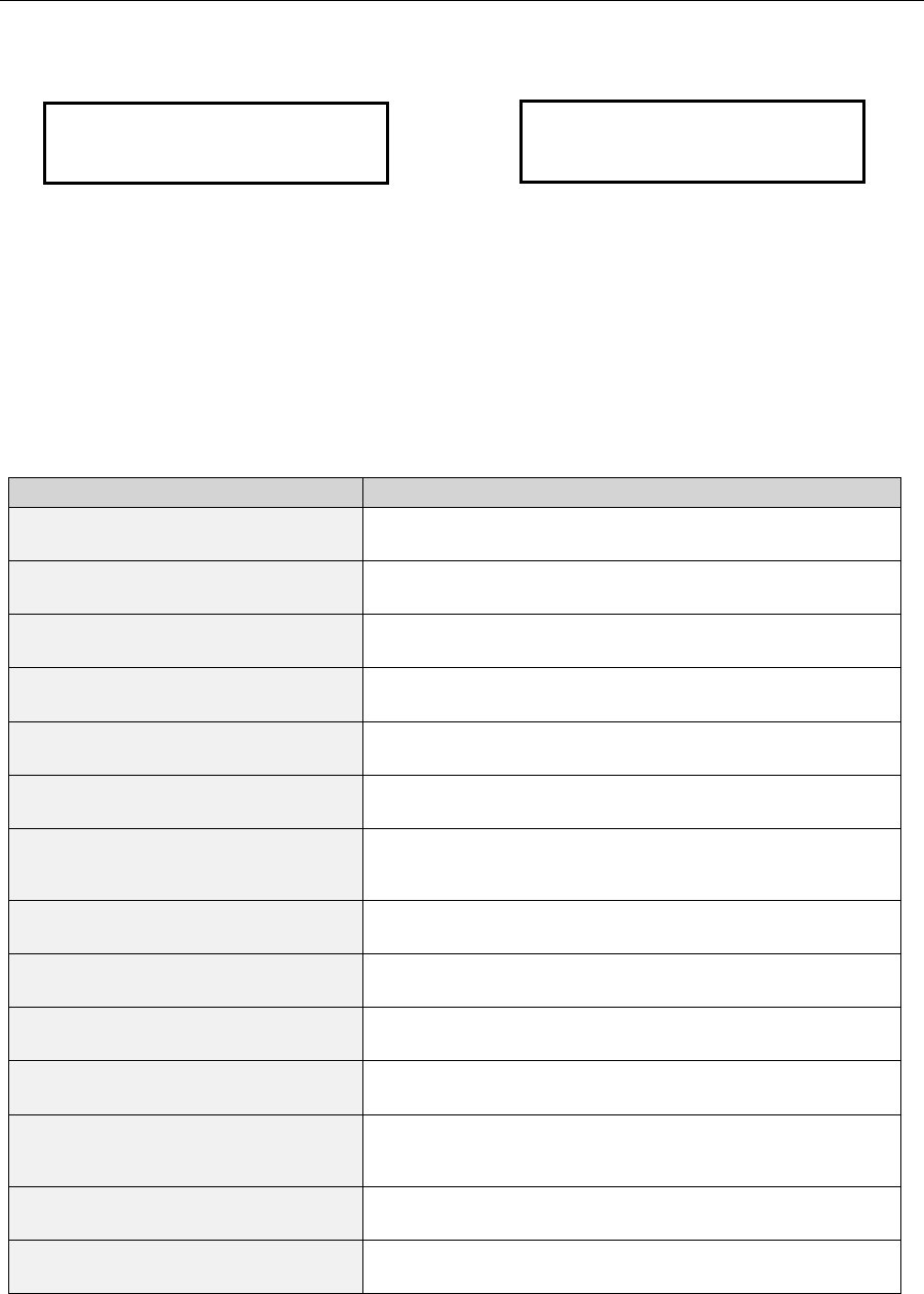
4.2 NIM Front Panel LCD
The LCD on the front panel of the NIM is a two-line display. The upper line alternately
displays the Radio ID, then the transmit power level and code. The lower line displays the
receive power level, master/slave status and the frequency channel. Figure 4-2 shows an
example of the alternating displays.
Wireless Internet Service Link - User's Manual Section 4: Operation
4-18 DRAFT
Figure 4-2. Example of Alternating LCD Contents
4.3 Troubleshooting
The table below is provided to assist in troubleshooting any difficulty you are likely to
encounter. (*** Following table to be revised and enhanced ***)
Symptoms Possible Causes
Both LEDs on bottom of RWM off. NIM not powered
Cable between RWM and NIM not connected or
damaged.
Green LED (Signal Quality/Power)
flashes once every two seconds. Polarity of antennas not the same at both locations.
Antenna cap colors must match at both location.
Antenna(s) not pointed properly..
RWM at other end not powered.
Master/Slave configured improperly. Only one end of
link must be a master and other a slave.
Pseudo-random Code Channel configured improperly.
Both RWMs must be configured with identical Pseudo-
random Code Channel.
Transmit Power Attenuation set too high at far end. Set
Transmit Power Attenuation to 0 at far end.
Channel Selection configured improperly. Both RWMs
must be configured with identical Frequency Channel.
One or both RWM is in Self-Test mode. Reconfigure
RWM to Normal mode.
Red LED (ARQ) continuously on. Interfering transmitter. Select a different Frequency
channel and Pseudo-random Code Channel.
Multiple RWMs operating at same site. Attach
synchronization cables between all RWMs at site and
assign Timing Leader numbers to all units.
LEDs appear normal, but no data. One RWM within link is configured in Loopback mode.
Reconfigure RWM to Normal mode.
One or both RWM within link is configured in Diagnostic
mode. Reconfigure RWM to Normal mode.
Table 4-1. Troubleshooting Chart
Los Angeles
RX: -38dBm (M/1)
TX: +22dBm (2357)
RX: -38dBm
(
M/1
)

Wireless Internet Service Link - User's Manual Section 4: Operation
4-19 DRAFT
4.4 Customer Support
If your problem can not be fixed by reading the troubleshooting section in this manual
(Chapter 4) and your local distributor can not resolve the situation, please contact
RadioConnect Corporation Technical Support at 310-338-3388 between 9:00 AM and
5:00 PM Pacific Standard Time.
RadioConnect Corporation
3521 W. Lomita Blvd., Suite 201
Torrance, CA 90505
Tel: (310) 891-2900
Fax: (310) 891-2922
Internet: www.radioconnect.com
e-mail: info@radioconnect.com

Wireless Internet Service Link - User's Manual
A
PPENDIX A: Technical Specifications – RWM
A-1 DRAFT
APPENDIX A Technical Specifications - RadioWire Modem
Operating frequency: 2,400 - 2,483.5 MHz
Burst clocking rate: 800 kbps
User-data throughput: 256 kbps, full-duplex
RF channel bandwidth: 25.6 MHz (main lobe)
RF channels: 3 total, of which 2 are non-overlapping
Receiver sensitivity: -90 dBm @ 1x10⁻⁶ BER
Transmit power: -2 dBm to +24 dBm
Range with: +24 dBi antenna
+20 dBi antenna
+14 dBi antenna
20 miles (32 km) – limited by protocol.
20 miles (32 km)
6 miles (10 km)
Data modulation: OQPSK
Code division channels: 16,384
Spreading method: Direct sequence
Spread code length: 32,768 chips
Process gain: 15 dB
Typical acquisition time: 10.5 sec. each way
Max signal loss time w/o loss of sync. More than 1 second
Antenna polarization: Circular - right or left
Built-in alignment LEDs: Signal strength, Packet errors
Size: 8.50”(dia.) x 4.00”(w/o antenna)
Environment temperature: -40 to +60 deg. C
Environment humidity: 10% - 100%, condensing
Wireless Internet Service Link - User's Manual
A
PPENDIX B: Technical Specifications - WISL NIM
B-1 DRAFT
APPENDIX B Technical Specifications -
WISL Network Interface Module
• Ports: User-data
Wireless modem
NIM-to-NIM synchronization
Console
• User interface: Serial (EIA-530) or Ethernet (10BaseT)
• Connectors: DB-25 (serial interface) or RJ-45 (Ethernet)
• Serial link layer: Protocol-independent
• Ethernet link layer: Bridge
• Power: 100 - 240 VAC (auto-sensing), < 1.0 Amp, 47-63 Hz
• NIM location: Stand-alone or rack-mount
• NIM size: 8.62”(W) x 8.85”(D) x 1.60”(H)
• Certifications: (pending)
• Operating temperature: 0 to +40 deg. C
• Operating humidity: 10% - 95%, non-condensing
User-data port (DB-25F/EIA-530 or RJ-45/10BaseT)
Wireless Modem port (DB-25F) NIM-to-NIM sync ports
Signal indicators Status display
Rear panel
Front panel Console port (DB-9F) - remove front panel for access

Wireless Internet Service Link - User's Manual
A
ppendix C: Link Configuration Worksheet
C-1 DRAFT
APPENDIX C Link Configuration Worksheet
Location A Location B
Name (for ref. only) Name (for ref. only)
Serial Number Serial Number
Location Location
Latitude Latitude
Longitude Longitude
Elevation of RWM Elevation of RWM
Distance (A to B)
Azimuth of Loc. B Azimuth of Loc. A
Antenna Type
(may be different at
the 2 locations)
[] Helical
[] 0.6 m dish
[] 1.0 m dish
Antenna Type [] Helical
[] 0.6 m dish
[] 1.0 m dish
Ant. Cap Color [] White [] Blue Ant. Cap Color Same as location A
Antenna Angle in
Vertical Plane Antenna Angle in
Vertical Plane
Pseudo-Random
Spreading Code #
(0 - 16,383)
Pseudo-Random
Spreading Code #
(0 – 16,383)
Same as location A
Freq. Channel [] CH1 (2,415.6 MHz)
[] CH2 (2,428.4 MHz)
[] CH3 (2,441.2 MHz)
[] CH4 (2,454.0 MHz)
[] CH5 (2,466.8 MHz)
Freq. Channel
Same as location A
Master or Slave
(one end must be
Master, other end
must be Slave)
Master or Slave
Sync Generator
Status
[] None [] Primary
[] Secondary
[] Tertiary
Sync Generator
Status
[] None [] Primary
[] Secondary
[] Tertiary
Transmit Power
(If manual, specify
value from +24 dB
to –14 dB)
[] Auto [] Manual Transmit Power [] Auto [] Manual

Wireless Internet Service Link - User's Manual
A
ppendix D: Network Interface Specification (Serial)
D-1 DRAFT
APPENDIX D Network Interface Specification (Serial)
Pin Assignments on User data port (DB-25F) when interface set to:
Pin # EIA-530 EIA-530-A V.35
1 Shield Shield Shield
2 Transmitted Data BA (A) Transmitted Data BA (A) Transmitted Data TxD (A)
3 Received Data BB (A) Received Data BB (A) Received Data RxD (A)
4 Request To Send CA (A) Request To Send CA (A) Request To Send RTS
5 Clear To Send CB (A) Clear To Send CB (A) Clear To Send CTS
6 DCE Ready CC (A) DCE Ready CC Data Set Ready DSR
7 Signal Common AB Signal Common AB Signal Common
8 Received Line Signal
Detector CF (A) Received Line Signal
Detector CF (A) Data Channel Received
Line Signal Detector DCD
9 Receiver Signal Element
Timing (DCE source) DD (B) Receiver Signal Element
Timing (DCE source) DD (B) Receiver Signal Element
Timing RxC (B)
10 Received Line Signal
Detector CF (B) Received Line Signal
Detector CF (B)
11 Transmit Signal Element
Timing (DTE source) DA (B) Transmit Signal Element
Timing (DTE source) DA (B) Transmitter Signal Element
Timing (terminal source)
12 Transmit Signal Element
Timing (DCE source) DB (B) Transmit Signal Element
Timing (DCE source) DB (B) Transmitter Signal Element
Timing TxC (B)
13 Clear To Send CB (B) Clear To Send CB (B)
14 Transmitted Data BA (B) Transmitted Data BA (B) Transmitted Data TxD (B)
15 Transmit Signal Element
Timing (DCE source) DB (A) Transmit Signal Element
Timing (DCE source) DB (A) Transmitter Signal Element
Timing TxC (A)
16 Received Data BB (B) Received Data BB (B) Received Data RxD (B)
17 Receiver Signal Element
Timing (DCE source) DD (A) Receiver Signal Element
Timing (DCE source) DD (A) Receiver Signal Element
Timing RxC (A)
18 Local Loopback LL Local Loopback LL Local Loopback
19 Request To Send CA (B) Request To Send CA (B)
20 DTE Ready CD (A) DTE Ready CD Data Terminal Ready DTR
21 Remote Loopback RL Remote Loopback RL Loopback/Maintenance
22 DCE Ready CC (B) Ring Indicator CE
23 DTE Ready CD (B) Signal Common AC Signal Common
24 Transmit Signal Element
Timing (DTE source) DA (A) Transmit Signal Element
Timing (DTE source) DA (A) Transmit Signal Element
Timing (terminal source)
25 Test Mode TM Test Mode TM Test Mode

Wireless Internet Service Link - User's Manual
A
ppendix E: Network Interface Specification (Ethernet
)
E-1 DRAFT
APPENDIX E Network Interface Specification (Ethernet)

Wireless Internet Service Link - User's Manual
A
ppendix F: RWM-To-NIM Cable Specification
F-1 DRAFT
APPENDIX F RWM-To-NIM Cable Specification
The RadioWire RF Modem uses a square-flange AMP Series 2 Circular Plastic Connector
receptacle P/N 205840-3 on the housing. The RWM-to-NIM cable mates to the RWM using
an AMP P/N 205839-3. The other end of the cable mates to the NIM using a DB-25
connector - male on the cable, female on the NIM rear panel.
The following table shows the signals and cable pin-outs:
Signal Name Pin Numbers on
AMP Connector
(at RWM end) Wire Colors Pin Numbers on
DB-25 Connector
(at NIM end)
GND 1 Black 1
+10 TO +28 VDC 2 Red 2
TXHS+ 7 Orange 7
TXHS- 8 Yellow 8
RXHS+ 9 Violet 9
RXHS- 10 Gray 10
TXHSC+ 11 Pink 11
TXHSC- 12 Tan 12
RXHSC+ 13 White/Blue 13
RXHSC- 14 White/Orange 14
TXSCP+ 15 White/Green 15
TXSCP- 16 White/Brown 16
RXSCP+ 17 White/Gray 17
RXSCP- 18 Red/Blue 18
STATUS+ 19 Red/Green 19
STATUS- 20 Red/Brown 20
TXSYNC+ 21 Red/Gray 21
TXSYNC- 22 Green/Blue 22
CHASSIS GND 23 Bare wire 23
N/C 24 24
N/C 25 25
N/C 26
N/C 27
N/C 28
Table F-1. Interface Pin Outs
TP
TP
TP
TP
TP
TP
TP
TP
Twisted
Pair (TP)