Radwin 5XACMOD3C 5 GHz 802.11ac 3x3 RF Module User Manual UM Transportation 4 5 10 4Regulation
Radwin Ltd. 5 GHz 802.11ac 3x3 RF Module UM Transportation 4 5 10 4Regulation
Radwin >
User Manual

DEPLOYMENTGUIDE
TRANSPORTATIONFIBERINMOTION
BROADBANDTRAINTOGROUNDCOMMUNICATION
Release4.5.10

FinMDeploymentGuide Release4.5.10 i
TableofContents
Chapter1:Introduction
1.1ScopeofthisDocument ...................................................................................................... 1‐1
1.2TransportationFiberinMotionOverview ............................................................................ 1‐1
1.2.1MajorComponents...................................................................................................... 1‐2
TBS (Transportation Base Station) units...............................................................1‐3
TBS antennas.....................................................................................................1‐3
PoEs..................................................................................................................1‐3
TMUs (Transportation Mobile Units).....................................................................1‐4
TMU antennas....................................................................................................1‐4
ISUs..................................................................................................................1‐4
OSUs.................................................................................................................1‐5
1.2.2Accessories .................................................................................................................. 1‐5
1.2.3ManagementandConfigurationTools ....................................................................... 1‐5
RADWIN Configurator tool ..................................................................................1‐5
RADWIN Air Link Performance Monitoring tool......................................................1‐5
1.3Applications......................................................................................................................... 1‐6
1.3.1Operational ................................................................................................................. 1‐6
1.3.2PassengerServices ...................................................................................................... 1‐6
1.4Features............................................................................................................................... 1‐6
1.4.1General........................................................................................................................ 1‐6
1.4.2MobilityCapabilities.................................................................................................... 1‐6
1.4.3OnboardMobileUnits ................................................................................................. 1‐6
1.5DocumentNotifications ...................................................................................................... 1‐7
Chapter2:SiteInstallation
2.1ScopeofThisChapter.......................................................................................................... 2‐1
2.2Wayside............................................................................................................................... 2‐1
2.2.1Overview ..................................................................................................................... 2‐1
General Guidelines .............................................................................................2‐1
Power................................................................................................................2‐1
Minimum Recommended Distances......................................................................2‐1
General Mounting Arrangement...........................................................................2‐2
2.2.2TBSMounting.............................................................................................................. 2‐4
TBS Mounting on a vertical pole ..........................................................................2‐6
TBS mounting on a horizontal pole......................................................................2‐9
TBS mounting on a wall....................................................................................2‐13
2.2.3PoEDevicesfortheTBS ............................................................................................. 2‐16
2.2.4TBSAntennas ............................................................................................................ 2‐17
TBS Antenna Mounting on a Vertical Pole...........................................................2‐18
TBS Antenna Mounting on a Horizontal Pole.......................................................2‐21
TBS Antenna Mounting on a Wall ......................................................................2‐22
TBS Antenna Mounting Kit Adaptor....................................................................2‐22
2.2.5TBSExternalConnections .......................................................................................... 2‐25
2.2.6SynchronizationUnits................................................................................................ 2‐25
Indoor Synchronization Unit (ISU) .....................................................................2‐25
Outdoor Synchronization Unit (OSU)..................................................................2‐26
2.2.7ExternalGPSAntenna ............................................................................................... 2‐27
2.2.8LightningProtectionUnit(LPU)................................................................................. 2‐28
2.2.9Waterproofing........................................................................................................... 2‐31
2.3On‐board ...........................................................................................................................2‐33
2.3.1Overview ................................................................................................................... 2‐33
General Guidelines ...........................................................................................2‐33

FinMDeploymentGuide Release4.5.10 ii
Power..............................................................................................................2‐33
General Mounting Arrangement.........................................................................2‐33
2.3.2TMUMounting.......................................................................................................... 2‐33
Mounting on a wall...........................................................................................2‐43
TMU - External Connections..............................................................................2‐43
2.3.3PoEDevicesfortheTMU ........................................................................................... 2‐43
2.3.4TMUAntennas .......................................................................................................... 2‐44
2.3.5TMUExternalConnections ........................................................................................ 2‐47
2.4Grounding.......................................................................................................................... 2‐47
TBS and OSU...................................................................................................2‐47
TMU................................................................................................................2‐48
FinM PoE .........................................................................................................2‐48
External PoE ....................................................................................................2‐49
ISU .................................................................................................................2‐50
Antennas.........................................................................................................2‐50
Chapter3:NetworkGuidelines
3.1ScopeofThisChapter.......................................................................................................... 3‐1
3.2Overview ............................................................................................................................. 3‐1
3.3WaysideNetwork................................................................................................................ 3‐1
3.4On‐boardNetwork .............................................................................................................. 3‐3
3.5On‐boardPhysicalConnectivity .......................................................................................... 3‐4
3.6WaysideCoreRouter .......................................................................................................... 3‐5
3.7BasicIPSchemeandDataFlowPath................................................................................... 3‐5
3.8RecommendedVLANAssignment....................................................................................... 3‐7
3.9InterBaseHandover(IBHO)UpdateMessage .................................................................... 3‐9
3.10IntraTrainHandover(ITHO)UpdateMessage................................................................ 3‐12
Chapter4:ConfiguringtheRadioNetwork
4.1ScopeofThisChapter.......................................................................................................... 4‐1
4.2ConnectingtotheUnits ...................................................................................................... 4‐1
4.3AbouttheConfiguratorTool ............................................................................................... 4‐1
4.3.1MethodofOperation .................................................................................................. 4‐2
4.4UsingtheConfiguratorTool ................................................................................................ 4‐2
4.4.1MainTab ..................................................................................................................... 4‐2
4.4.2ProjectTab .................................................................................................................. 4‐5
Upper Table.......................................................................................................4‐5
Lower Table: Quality of Service (QoS) Options .....................................................4‐9
4.4.3LineTab ..................................................................................................................... 4‐12
4.4.4TowersTab ................................................................................................................ 4‐15
4.4.5TrainTab ................................................................................................................... 4‐17
4.5InterferenceMitigationforCo‐channelNeighbors........................................................... 4‐17
4.5.1BasicSituation........................................................................................................... 4‐18
4.5.2NecessaryPre‐Conditions.......................................................................................... 4‐18
Activation Conditions ........................................................................................4‐19
De-Activation Conditions...................................................................................4‐19
4.5.3MethodofOperation ................................................................................................ 4‐20
4.5.4ConfiguringtheCo‐ChannelNeighborInterferenceMitigationOption .................... 4‐21
4.6ConfiguringNetworkUnits................................................................................................ 4‐25
Configuring an Individual Unit:..........................................................................4‐25
Configuring Many Units at Once:.......................................................................4‐25
4.6.1ConfiguringTransportationBaseStations(TBSs)...................................................... 4‐25
To re-configure a unit that is already installed:...................................................4‐26
4.6.2ConfiguringTransportationMobileUnits(TMUs)..................................................... 4‐27
To re-configure a unit that is already installed in the field: ..................................4‐28
4.6.3ConfiguringIndoorSynchronizationUnits(ISUs) ...................................................... 4‐29
To re-configure a unit that is already installed in the field: ..................................4‐30

FinMDeploymentGuide Release4.5.10 iii
4.7ConfiguratorMessages ..................................................................................................... 4‐31
AppendixA:AntennaGuidelines
A.1ForDeploymentinUS/Canada............................................................................................ A‐1
AppendixC:RevisionHistory

FinMDeploymentGuide Release4.5.10 iv

FinMDeploymentGuide Release4.5.10 1‐1
Chapter1:Introduction
1.1ScopeofthisDocument
ThispublicationshowshowtoinstallandoperateRADWIN’sTransportationFiberinMotion
(FiberinMotionorFinM)solution.
Thispublicationisaddressedprimarilytosystemintegratorsaswellasinstallingtechnicians.
1.2TransportationFiberinMotionOverview
TransportationFiberinMotionisatrain‐to‐waysidecommunicationssolutionthatensures
continuoushigh‐speedwirelessconnectivitybetweentherollingstock,thetracksandcontrol
center.
TheTransportationFiberinMotionsystemconsistsofpowerfulbasestationsdeployedalong
thetracksthatconnecttomobileunitsinstalledonboardtherollingstock.Thesolution
operatesinchallengingoutdoorconditionsandundergroundtunnels.
FinMDeploymentGuide Release4.5.10 1‐2
TransportationFiberinMotionOverview Introduction
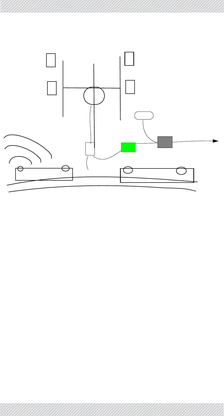
Figure1‐1:FiberinMotionOverview
AFiberinMotionsolutionworksasfollows:
•TBS(TransportationBaseStation)unitsareinstalledonpolesorwallseitheroutdoorsor
inatunnel,andareequippedwithantennas(usually4),
•TheTBSunitscommunicatewiththebackhaulnetworkviaaPoEdeviceorfiber,
•TheTBSunitstransmitto/receivefromTMUs(TransportationMobileUnits)installedon
boardrollingstock(alsoequippedwithantennasfortheTMUs),andlocatedwithinthe
beamoftheTBSantennas,
•TheTMUradios,alsopoweredbyPoEdevices,providecommunicationconnectionsfor
on‐boardequipmentsuchasroutersandWiFidevices.
•IndoorSynchronizationUnit/OutdoorSynchronizationUnits(ISU/OSU)synchronizethe
transmissionofbelowgroundTBSunits.
TBS
Antennas
Pole/Wall
TMUs
Rollingstock
PoE
ISU/OSU
StationSwitch Coreswitch Network
&Backhaul
FinMDeploymentGuide Release4.5.10 1‐3
MajorComponents Introduction
1.2.1MajorComponents
ThemajorcomponentsoftheTransportationFiberinMotionsolutionareshownbelow:
TBS(TransportationBaseStation)units
TBSunitscommunicatewiththebackhaulnetworkviaaPoEdeviceorfiber,andtransmitto/
receivefromTMUs(TransportationMobileUnits)installedonboardrollingstock.
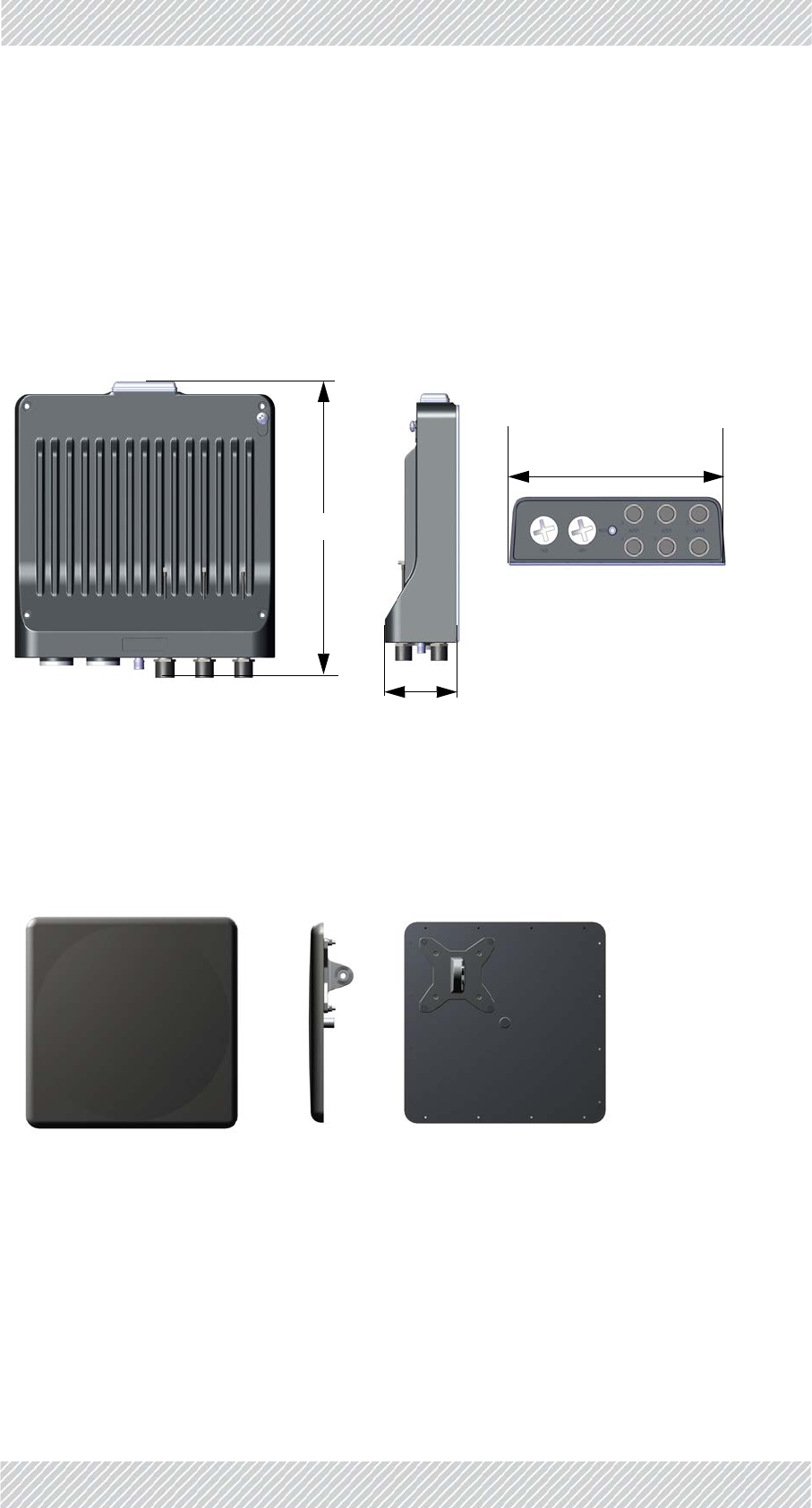
TBSantennas
Althoughtherearemanydifferenttypesofantennas(seeAppendixA,AntennaGuidelinesfor
alistofpermittedantennas),werecommendusingflatantennasliketheoneshownhere,
availablefromRADWIN:
Figure1‐2:TBSunit
Figure1‐3:TBSantenna
280mm
75mm
250mm
FinMDeploymentGuide Release4.5.10 1‐4
MajorComponents Introduction
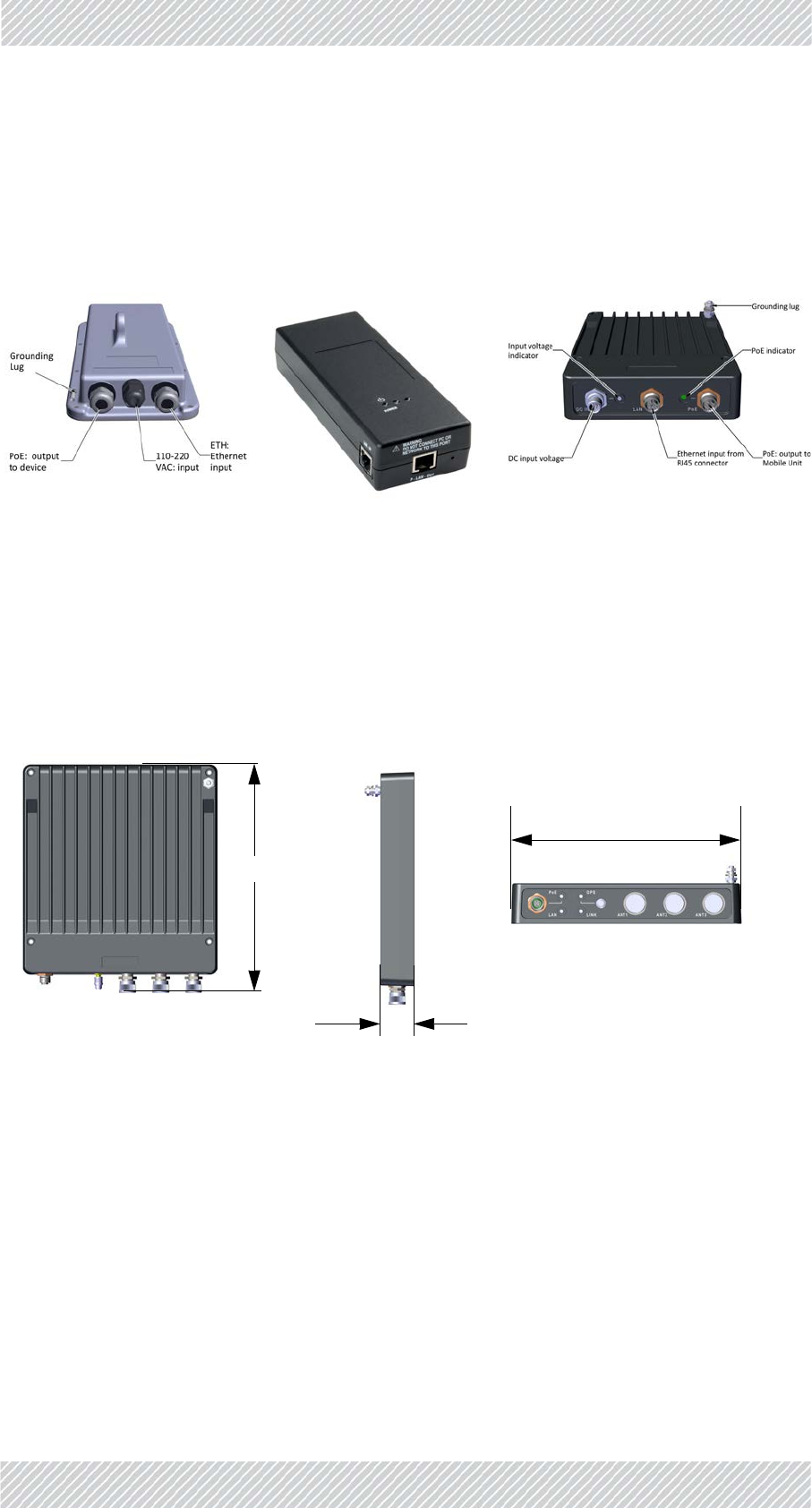
PoEs
Power‐over‐ethernetdevicesareusedtosupplybothpowerandnetworkcommunicationsto
theTBS,TMU,andOSUs.UseonlyPoEsrecommendedbyRADWIN.Inaddition,theTMUcan
besuppliedfromanalternativePoE,asshown.
WhenworkingwiththeTMU,notethataspecialPoE‐TMUcablemustbeused.
TMUs(TransportationMobileUnits)
TMUradios,alsopoweredbyPoEdevices,transmitto/receivefromTBSsinstalledonwayside
polesorwalls,andprovidecommunicationconnectionsforon‐boardequipmentsuchas
routersandWiFidevices.
OutdoorPoE IndoorPoE PoEfortheTMU
Figure1‐4:PoEUnits
Figure1‐5:TMUradio
275mm
40mm
230mm
FinMDeploymentGuide Release4.5.10 1‐5
MajorComponents Introduction
TMUantennas
Useshark‐finantennas,installedontheroofoftherollingstock(seeAppendixA,Antenna
Guidelinesforalistofpermittedantennas):
Figure1‐6:Shark‐finantennaforTMU
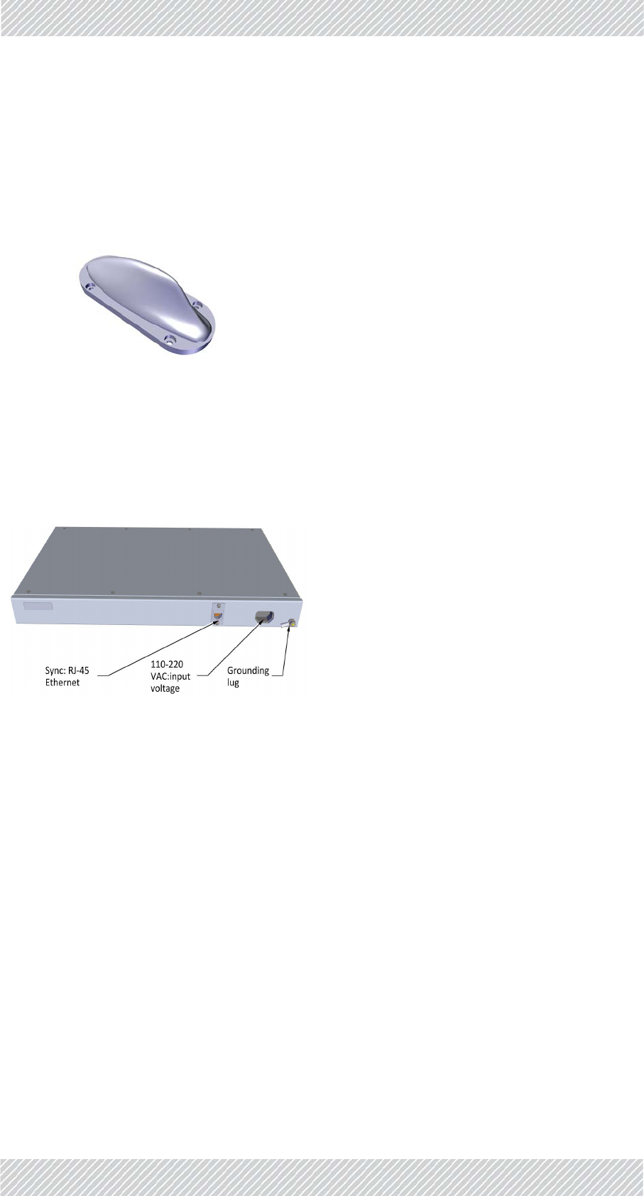
ISUs
IndoorSynchronizationUnitsareusedtosynchronizeTBStransmissions.TheISUsare
installedintunnels.
Figure1‐7:IndoorSynchronizationUnit

FinMDeploymentGuide Release4.5.10 1‐6
Accessories Introduction
OSUs
OutdoorSynchronizationUnitsareusedtosynchronizeTBStransmissions.TheOSUsare
basedonthesamehardwarecasingastheTBS,andareinstalledinoutdoorlocations.
Figure1‐8:OutdoorSynchronizationUnit
1.2.2Accessories
Youwillalsoneedsomeofthefollowingaccessories:
•Lightningprotectorunit‐forusewithoutdoorproducts
•CAT6cables‐variouslengthsforusewithradiosandPoEdevices
•Groundingcables
•AdditionalmountingkitsfortheantennasandPoEs‐eachantennaandeachexternal
PoEinstalledonapoleneedsamountingkit.
1.2.3ManagementandConfigurationTools
RADWINConfiguratortool
Thistoolallowsyoutocarryoutbulkcommissioningofgroupsofradios,usuallyonatrackby
trackbasis.ItsuseiscoveredinRadioNetworkConfiguration.
RADWINAirLinkPerformanceMonitoringtool
TheAirLinkPerformanceMonitoring(ALPM)toolisanadvancedanalysistoolforRADWIN’s
FiberinMotionproductline.
TheALPMtoolaccumulatesallimportanteventsandinformationrelatedtoeachunitinthe
systemandtothetargettowhichithasalink.

FinMDeploymentGuide Release4.5.10 1‐7
Applications Introduction
1.3Applications
1.3.1Operational
•Real‐timeCCTVtransmission
•Levelcrossingdetection
•Onboardticketing
•Communications‐basedtraincontrol(CBTC)
1.3.2PassengerServices
•High‐speedinternetaccess
•PassengerInformationSystems
•Multimediaentertainment
1.4Features
1.4.1General
»Ethernetconnectivitybetweenbasestationandsubscriberunits
»AdvancedOFDM&MIMO2x2and3x3fornLOSandNLOSperformance
»Enhancedinterferencemitigationcapability
»Inter&intrasitesynctoreduceselfinterference
»Longrangebetweenbasestations
»Frequencybands‐4.9‐5.9GHz
»DedicatedBandwidthensuringSLA&latency
»Lowandconstantlatency–min<3ms,typical4to20ms
»Channelbandwidth–20/40/80MHz
»Regulationssupported‐FCC/IC/WPC/MII/Universal/JapaneseRegulations
1.4.2MobilityCapabilities
»Upto750MbpsperTBS
»Highspeed‐upto300Kmperhour/186milesperhour
»Upto16TMUsperTBS
»RADWINNetworkManagementSystemsupport
»SmartBandwidthManagement(SBM)usingdynamicbandwidthallocationtomaxi‐
mizeserviceproviderthroughputandadheretocustomerSLAs
1.4.3OnboardMobileUnits
»200MbpsaggregatethroughputperTMU

FinMDeploymentGuide Release4.5.10 1‐8
DocumentNotifications Introduction
»SupportscustomerSLAsbyassignmentofdedicatedbandwidthforuplinkanddown‐
linkperTMU,attheTBS
»SeparateuplinkanddownlinkconfigurableMaximumInformationRate(MIR)per
TMU
1.5DocumentNotifications
NotificationsconsistofWarnings,CautionsandNotes.
Warning:riskofdangertopersons.
Caution:riskofdamagetoequipmentorofservicedegradation
•Provideadditionalbackground
•Offerarecommendation
•Remindyouofsomethingthatshouldbekeptinmind

FinMDeploymentGuide Release4.5.10 2‐1
Chapter2:SiteInstallation
2.1ScopeofThisChapter
ThischapterdescribeshowtoinstalltheequipmentfortheTransportationFiberinMotion
solution.
2.2Wayside
TheFiberinMotionsolutionusesmultipleantennastoenableMIMOandDiversitymodes.
Thesolutionreliesonantennaspacing,aswellasdualpolarization/dualslantedantennasto
differentiatetheradiostreams.
2.2.1Overview
GeneralMountingArrangement
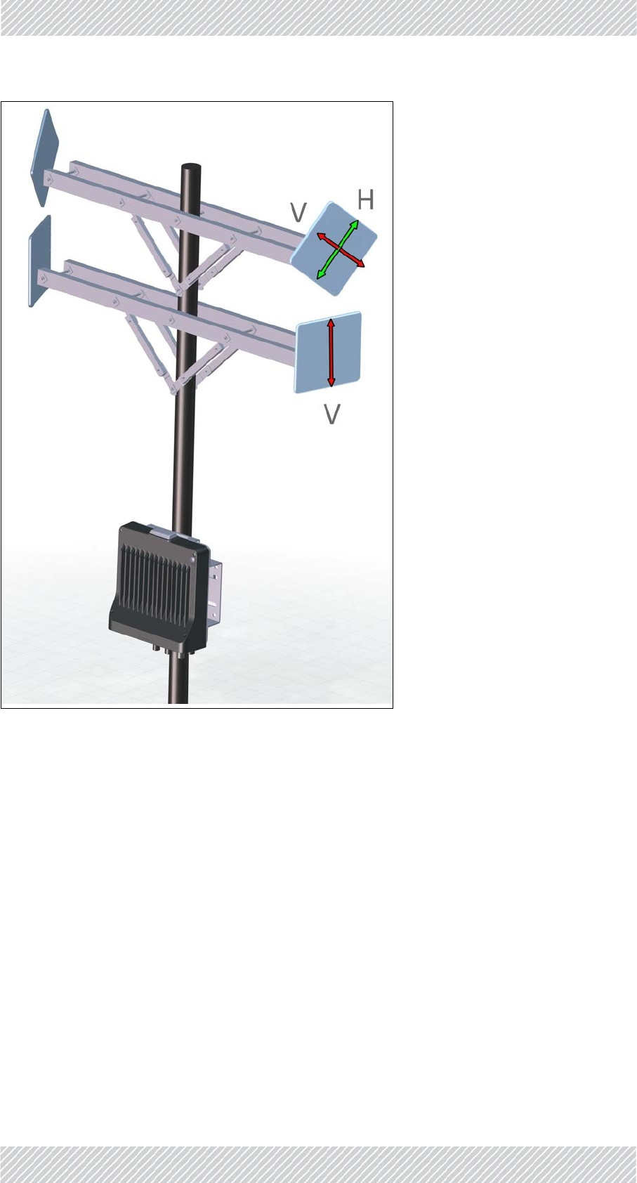
TheTBScanbemountedonapoleorawall,togetherwithitsantennas,LPUsandPoEdevice.
ToenablebetterMIMOconditions,theantennasshouldbedividedbetweenverticaland
horizontalpolarizations.Figure 2‐1showsaschematicviewwiththesepolarizations.
•Placethetower/TBSatthelocationdeterminedbythesitesurvey.
•Makesurethereissufficientline‐of‐sighttowardsthetracksegmenttheantennas
willcover
•Makesurethattherearenoobstaclesdirectlyinfrontoftheantennas
•Thelowestantennamustbehigherthanthehighestrailcarontheline
FinMDeploymentGuide Release4.5.10 2‐2
Overview SiteInstallation
Figure2‐1:TBS‐BaseStationmountingwithantennas(outside)

FinMDeploymentGuide Release4.5.10 2‐3
Overview SiteInstallation
Table2‐1:TBS‐BaseStationmountingwithantennas(tunnel)
Power
•UsethePoEtosupplypowertotheTBS
•UsethePoEortheSFPfiberconnectiontoprovideaserviceconnectiontothe
TBS.
•InstalltwoLightningProtectionUnits(LPU):OneclosetotheTBS,andtheother
closetothePoE.
MinimumRecommendedDistances
Therearetwoantennasforeachdirection:Aisforapproachingtrains,andBisfor
recedingtrains(seeFigure 2‐1).Separatetheantennasasmuchaspossible,and
maintainthefollowingminimaldistances:
•Recommendedverticalseparationbetweeneachantennais1.0m.
FinMDeploymentGuide Release4.5.10 2‐4
TBSMounting SiteInstallation
2.2.2TBSMounting
TheTBScanbemountedonaverticalorhorizontalpole,oronawall.
•Verticalpole:seepage 2‐6fordirectionsrelevanttoallsizes.
•Thinpole:seepage 2‐6.
•Mediumpole:seepage 2‐8
•Thickpole:seepage 2‐8
• Horizontalpole:seepage 2‐9fordirectionsrelevanttoallsizes.
•Thinpole:seepage 2‐11.
•Mediumpole:seepage 2‐12
•Thickpole:seepage 2‐13
• Wall:TheTBScanbemountedonawall,seepage 2‐13.
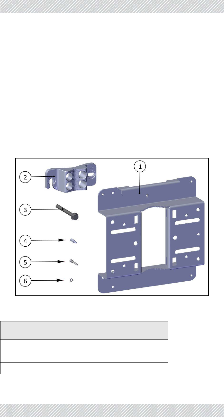
Checkthepackagecontents:
Figure2‐2:TBSmountingkitpackagecontents
Table2‐2:TBSmountingkitpackagecontents
Item
No. Description Quantity
1Baseplate 1
2Poleclamp 1
3HexscrewwithflangeM8x90 2

FinMDeploymentGuide Release4.5.10 2‐5
TBSMounting SiteInstallation
4StandoffsM4x16 4
5AllenscrewsM4x30 4
6Washersforallenscrews 4
Table2‐2:TBSmountingkitpackagecontents(Continued)
Item
No. Description Quantity
FinMDeploymentGuide Release4.5.10 2‐6
TBSMounting SiteInstallation
TBSMountingonaverticalpole
Allsizes
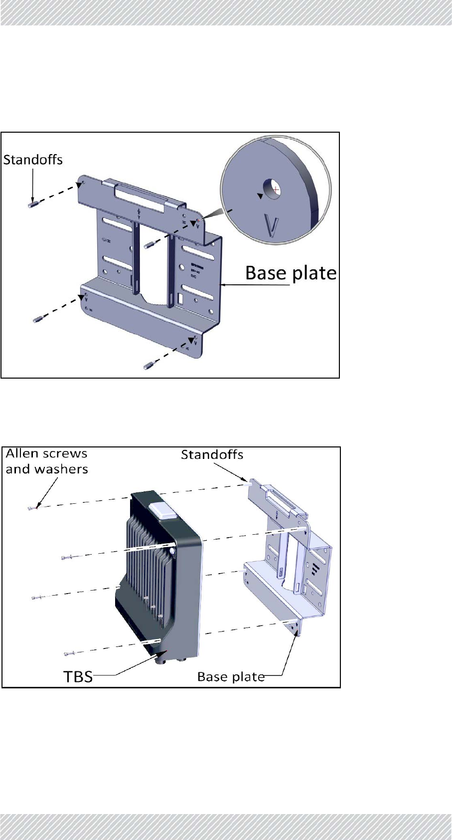
1. Fastenthestandoffstothebaseplateintheholeslabeled“V”asshown:
Figure2‐3:Fastenstandoffstobaseplate(forverticalpole)
2. PlacetheTBSasshownoverthestandoffs,andusingtheAllenscrewsandwashers,fasten
theTBStothebaseplate.
Figure2‐4:FastenTBStobaseplate(forverticalpole)
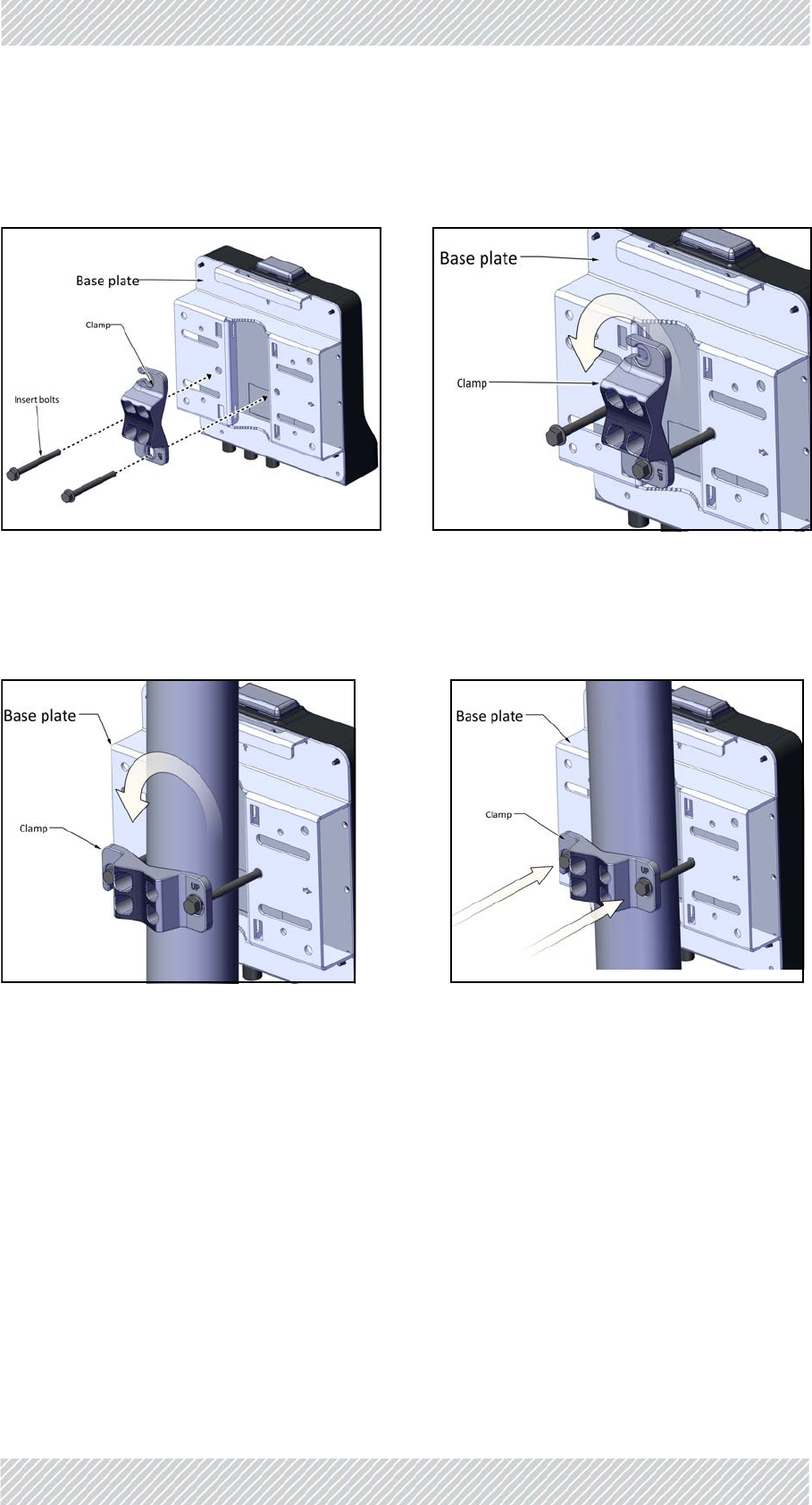
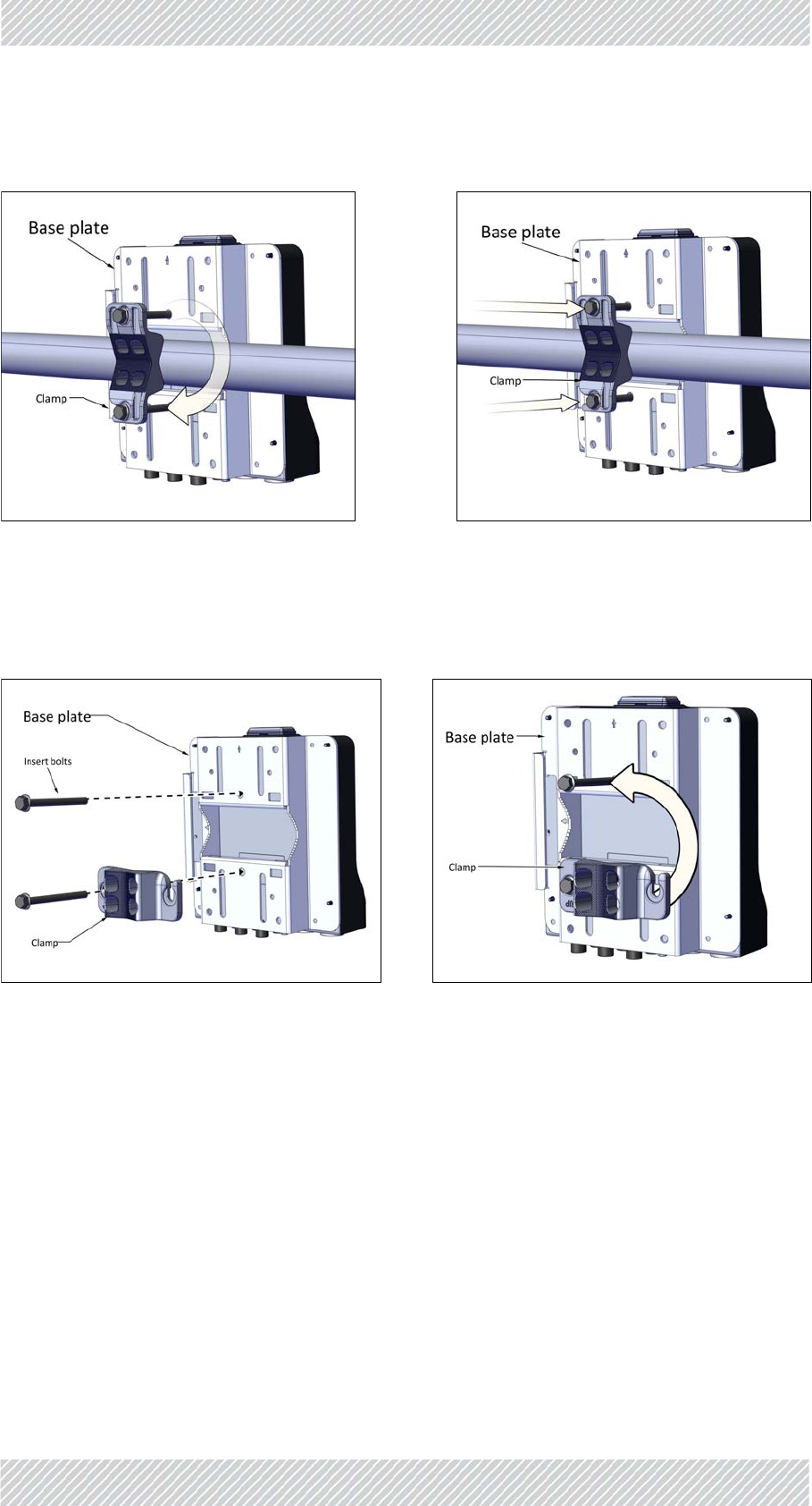
VerticalPole‐thin
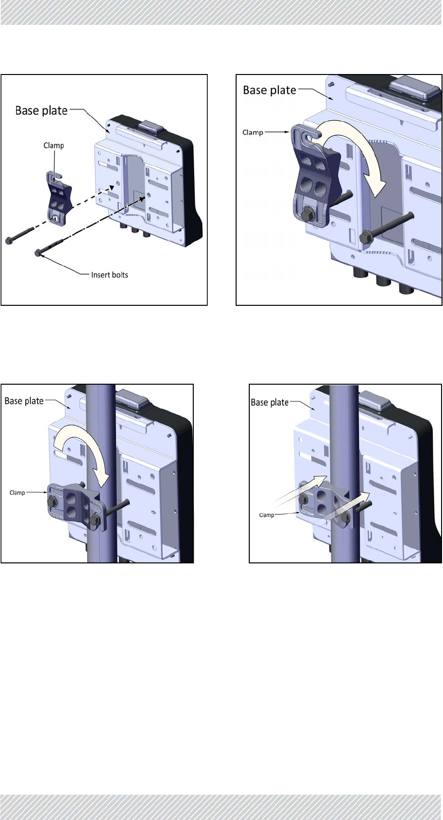
1. Diameter3/4to11/2:BeforeraisingtheTBSonthepole,positionthepoleclampasshown
inthefollowingtwofigures.Donotcompletelytightenthebolts:
FinMDeploymentGuide Release4.5.10 2‐7
TBSMounting SiteInstallation
Thinpole(diameter3/4to11/2):Positionthepoleclampasshowninthefoll owing twofigures,donotcompletelytightenthebolts:
2. PlacethisassemblyonthepolewhereyouwanttomounttheTBS.Onceitisinplace,
rotatethepoleclampasshown,thentightenbothbolts.
Figure2‐5:Thinpole:Fastenclamptobase
plate
Figure2‐6:Thinpole:Donotcompletely
tightenbolts
Figure2‐7:Thinpole:Rotateclamp Figure2‐8:Thinpole:tightenbolts
FinMDeploymentGuide Release4.5.10 2‐8
TBSMounting SiteInstallation
Verticalpole‐medium
1. Diameter2to3:BeforeraisingtheTBSonthepole,positionthepoleclampasshownin
thefollowingtwofigures.Donotcompletelytightenthebolts:
2. PlacethisassemblyonthepolewhereyouwanttomounttheTBS.Onceitisinplace,
rotatethepoleclampasshown,thentightenbothbolts.
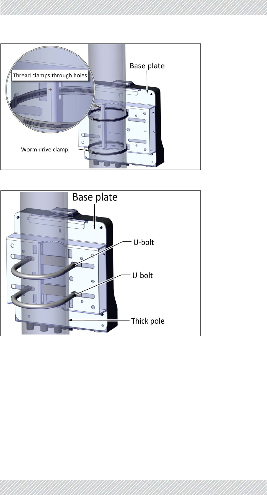
VerticalPole‐thick
1. Diameterlargerthan3:Usewormdriveclamps(notsupplied),threadedthroughtheholes
asshowninFigure 2‐13,orU‐bolts(notsupplied),fastenedusingtheholesasshownin
Figure 2‐14:
Figure2‐9:Mediumpole:Fastenclampto
baseplate
Figure2‐10:Mediumpole:Donotcom‐
pletelytightenbolts
Figure2‐11:Mediumpole:Rotateclamp Figure2‐12:Mediumpole:tightenbolts
FinMDeploymentGuide Release4.5.10 2‐9
TBSMounting SiteInstallation
Figure2‐13:Usingwormdriveclampsforathickpole
Figure2‐14:UsingU‐boltsforathickpole
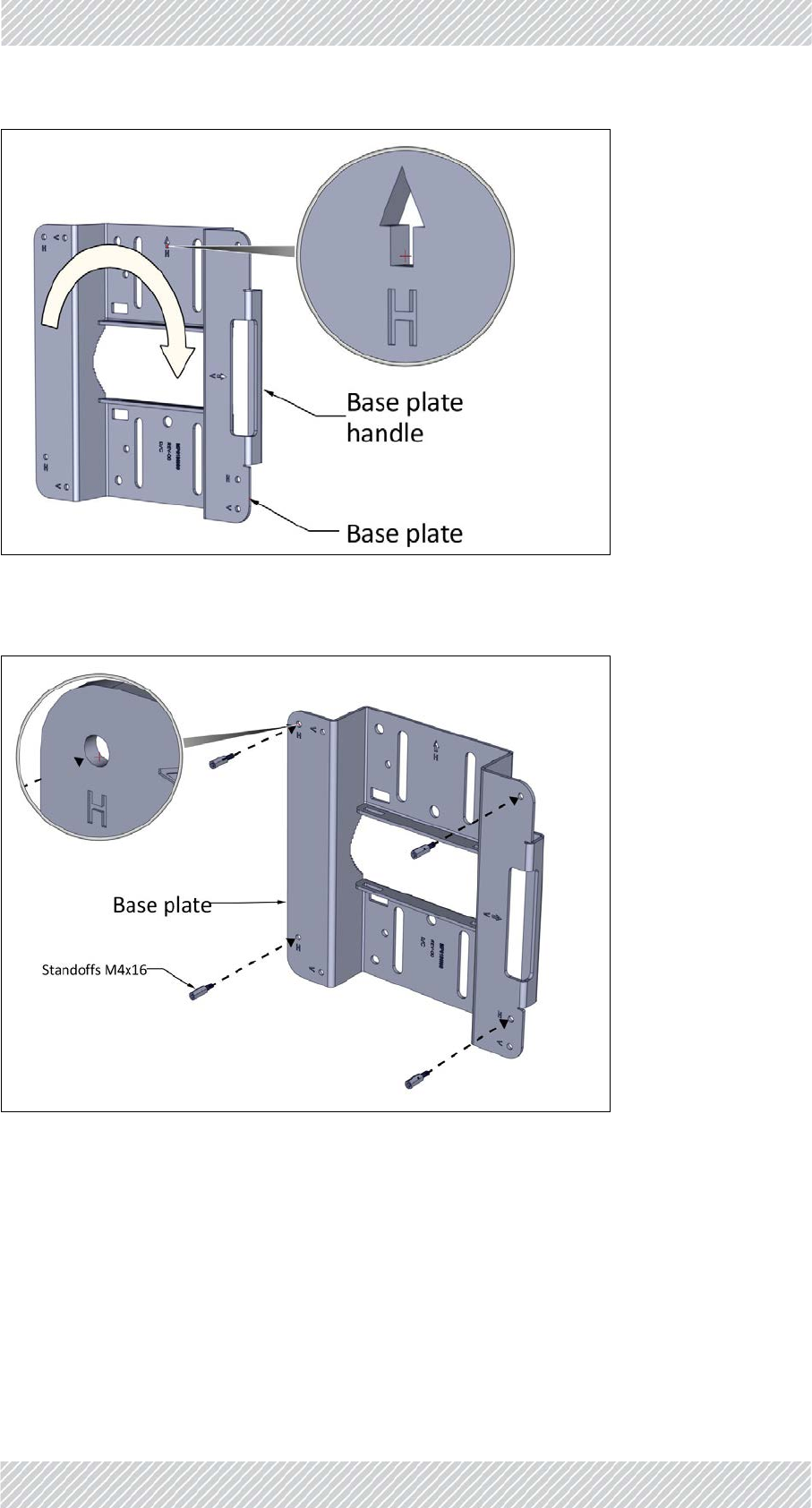
TBSmountingonahorizontalpole
Allsizes
1. BeforefasteningtheTBStothebaseplate(seeStep1.onpage 2‐6),rotatetheplateby90o
clockwise.Makesurethearrownexttothe“H”pointsup.
FinMDeploymentGuide Release4.5.10 2‐10
TBSMounting SiteInstallation
Figure2‐15:Rotatebaseplateclockwise90oforhorizontalpole
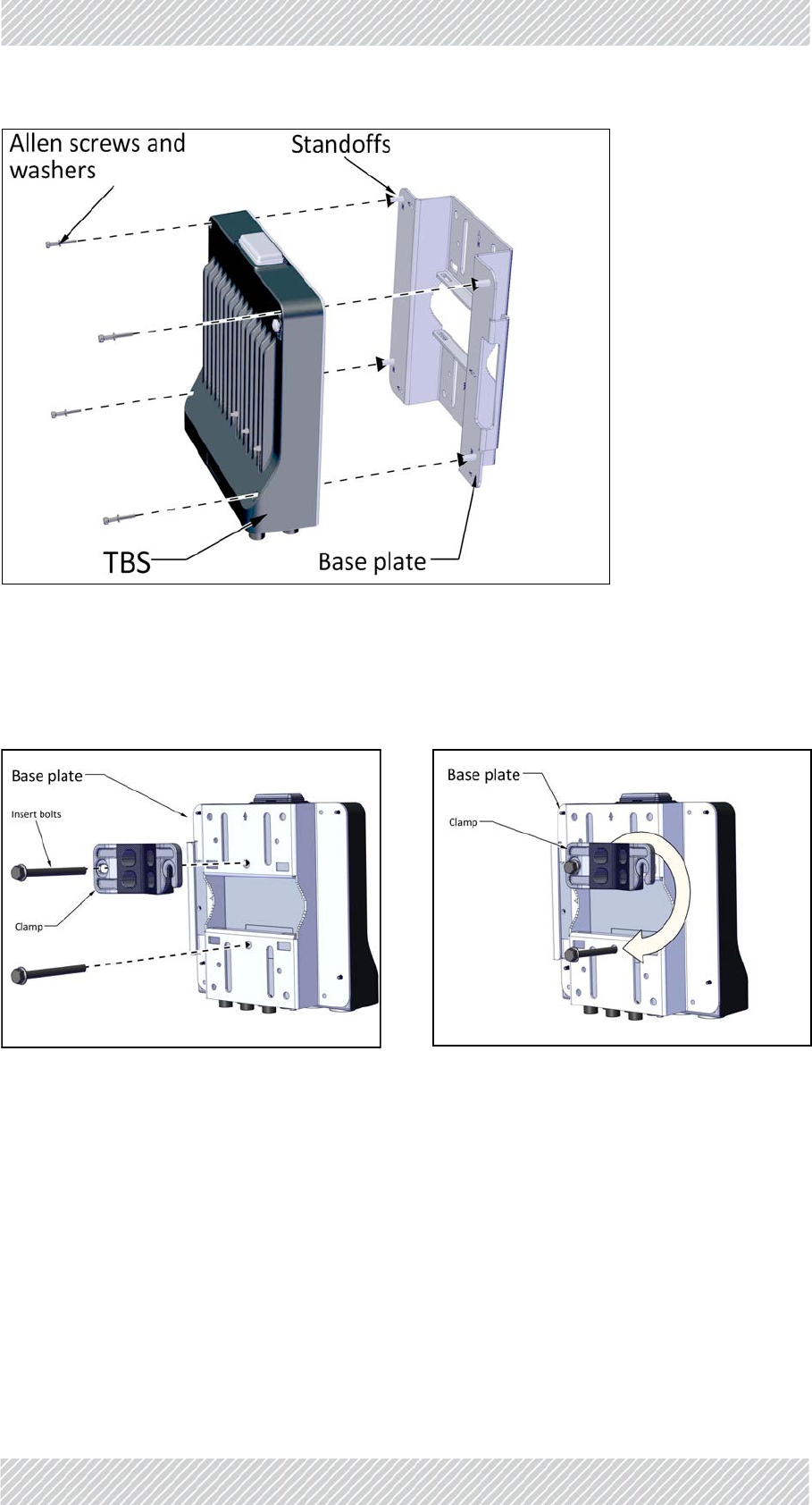
2. Fastenthestandoffstothebaseplateintheholeslabeled“H”asshown:
Figure2‐16:Fastenstandoffstobaseplate(forhorizontalpole)
3. PlacetheTBSasshownoverthestandoffs,andusingtheAllenscrewsandwashers,fasten
theTBStothebaseplate.
FinMDeploymentGuide Release4.5.10 2‐11
TBSMounting SiteInstallation
Figure2‐17:FastenTBStobaseplate(forhorizontalpole)
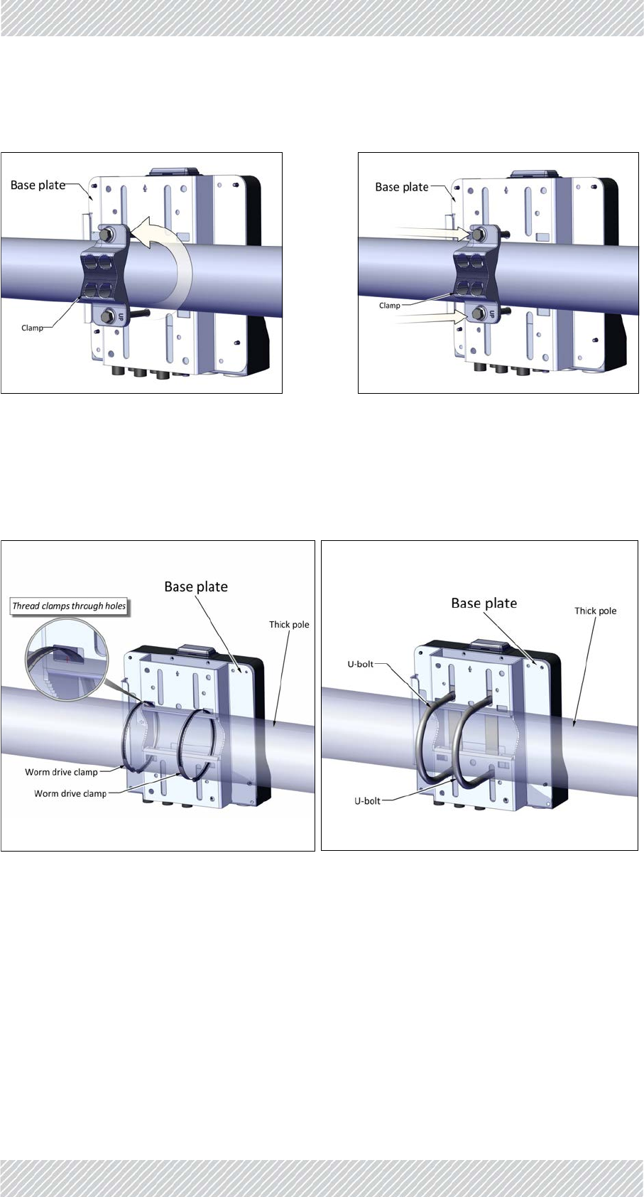
HoriztonalPole‐thin
1. Diameter3/4to11/2:BeforeraisingtheTBSonthepole,positionthepoleclampasshown
inthefollowingtwofigures.Donotcompletelytightenthebolts:
Thinpole(diameter3/4to11/2):Positionthepoleclampasshowninthefoll owing twofigures,donotcompletelytightenthebolts:
Figure2‐18:Thinpole:Fastenclamptobase
plate
Figure2‐19:Thinpole:Donotcompletely
tightenbolts
FinMDeploymentGuide Release4.5.10 2‐12
TBSMounting SiteInstallation
2. PlacethisassemblyonthepolewhereyouwanttomounttheTBS.Onceitisinplace,
rotatethepoleclampasshown,thentightenbothbolts.
HorizontalPole‐medium
1. Diameter2to3:BeforeraisingtheTBSonthepole,positionthepoleclampasshownin
thefollowingtwofigures.Donotcompletelytightenthebolts:
Figure2‐20:Thinpole:Rotateclamp Figure2‐21:Thinpole:tightenbolts
Figure2‐22:Mediumpole:Fastenclampto
baseplate
Figure2‐23:Mediumpole:Donotcom‐
pletelytightenbolts
FinMDeploymentGuide Release4.5.10 2‐13
TBSMounting SiteInstallation
2. PlacethisassemblyonthepolewhereyouwanttomounttheTBS.Onceitisinplace,
rotatethepoleclampasshown,thentightenbothbolts.
HoriztonalPole‐thick
1. Diameterlargerthan3:Usemetalbands(notsupplied),threadedthroughtheholesas
showninFigure 2‐26,orU‐bolts(notsupplied),fastenedusingtheholesasshownin
Figure 2‐27:
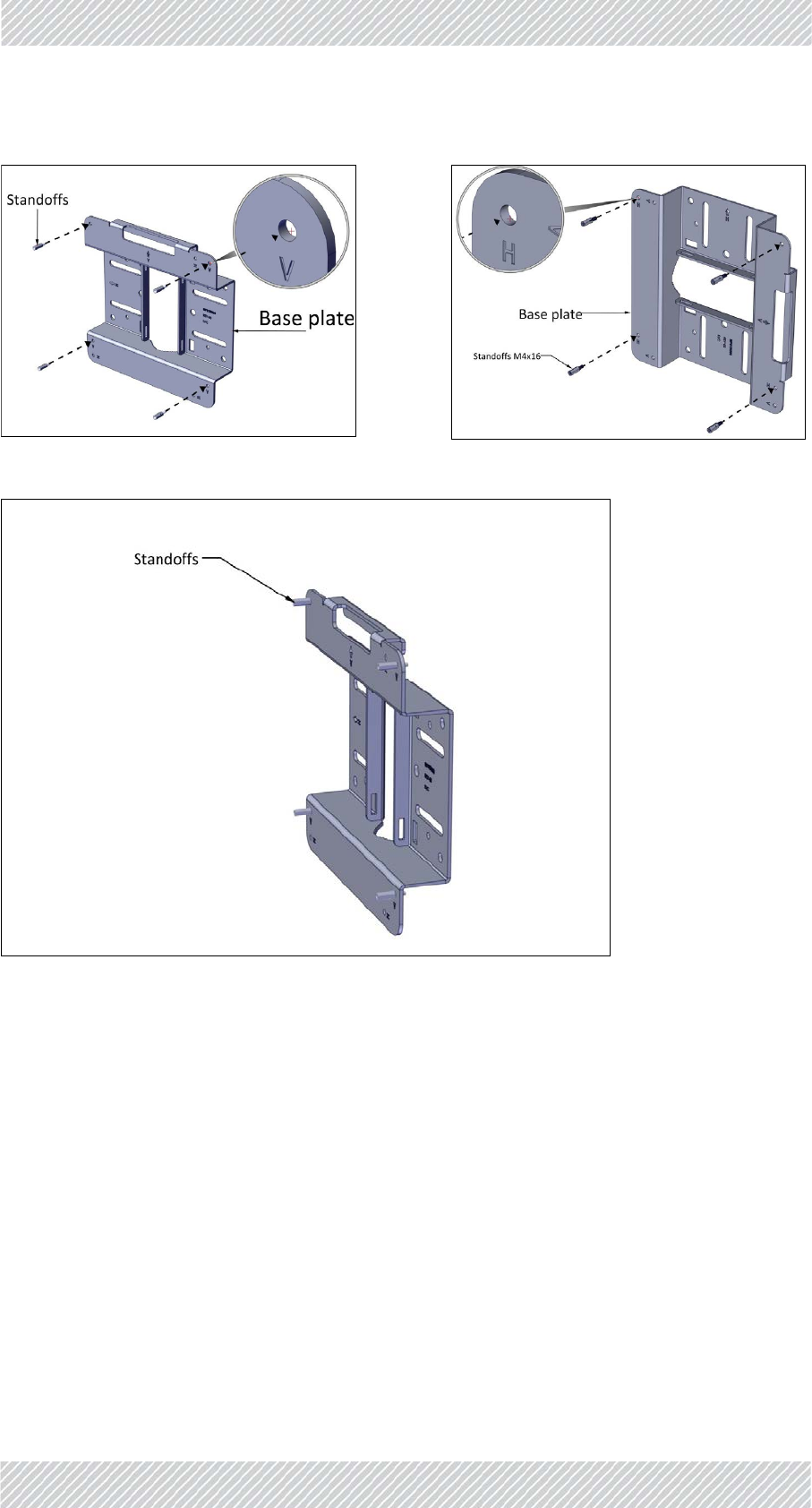
TBSmountingonawall
1. Fastenthestandoffstothebaseplateintheholeslabeled“V”or“H”,whicheverismore
convenient,asshown:
Figure2‐24:Mediumpole:Rotateclamp Figure2‐25:Mediumpole:tightenbolts
Figure2‐26:UsingmetalbandsforalargepoleFigure2‐27:UsingU‐boltsforalargepole
FinMDeploymentGuide Release4.5.10 2‐14
TBSMounting SiteInstallation
Figure2‐29:Standoffsfastenedtobaseplate
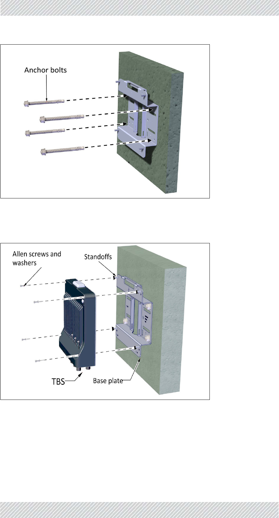
2. Useanchorboltstoattachbaseplatetoawall,asshown:
OR
<‐>
Figure2‐28:Fastenstandoffstobaseplate
FinMDeploymentGuide Release4.5.10 2‐15
TBSMounting SiteInstallation
Attachthebaseplatetoawallusing9mmdia.anchorbolts(notsupplied)intheholesindicated.
Figure2‐30:Attachbaseplatetowall
3. PlacetheTBSasshownoverthestandoffs,andusingtheAllenscrewsandwashers,fasten
theTBStothebaseplate.
Figure2‐31:FastenTBStobaseplateonwall
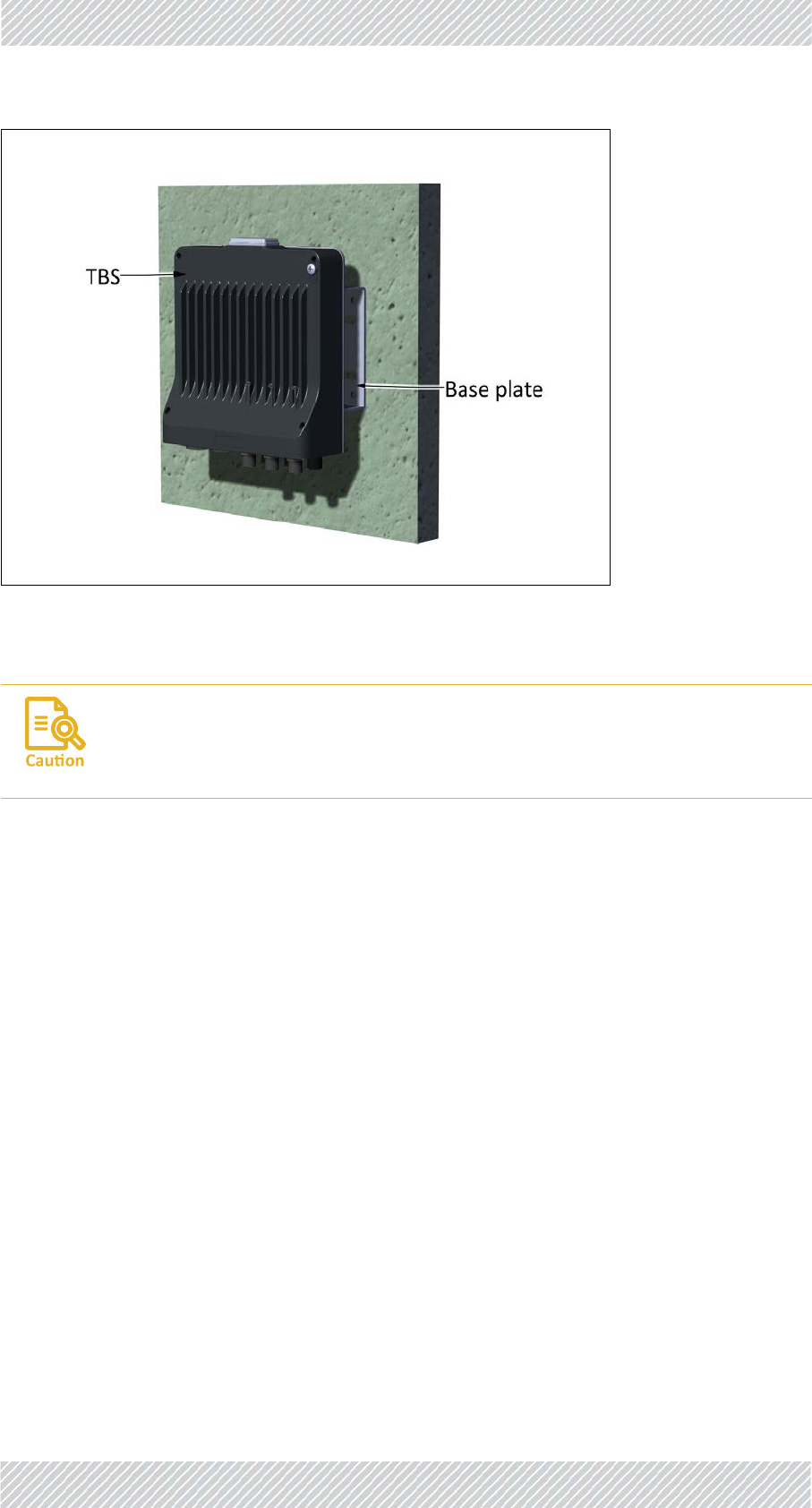
FinMDeploymentGuide Release4.5.10 2‐16
PoEDevicesfortheTBS SiteInstallation
Figure2‐32:TBSmountedonawall
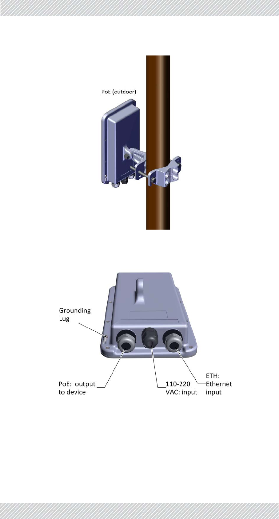
2.2.3PoEDevicesfortheTBS
TheTBSissuppliedbyaPoEdevice,mountedinthesamemannerasanantenna,orviaan
indoorunit,installedinanelectricalhut.
AlwaysmountaTBSwiththeconnectorsonthebottom.Nevermounta
unithorizontally.
FinMDeploymentGuide Release4.5.10 2‐17
TBSAntennas SiteInstallation
Figure2‐33:PoEmountedonapole
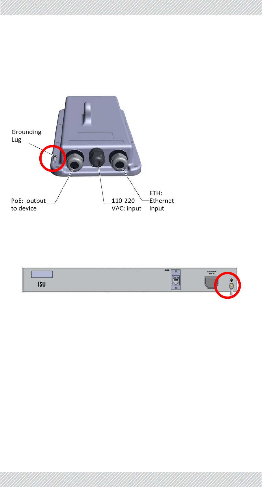
Figure2‐34:PoEexternalconnections
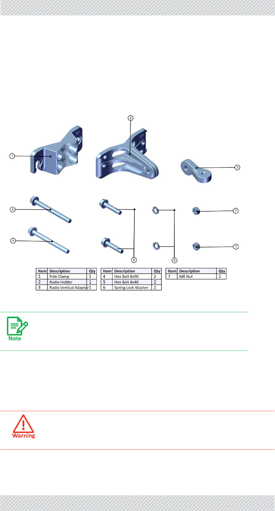
2.2.4TBSAntennas
Usetheantennamountingkit(differentfromtheTBSmountingkit)tomountaTBSantenna
onapoleorwall.ThesamemountingkitisusedtomountanexternalPoEdevice.
•Verticalpole:seepage 2‐19to
FinMDeploymentGuide Release4.5.10 2‐18
TBSAntennas SiteInstallation
•Thinpole:seepage 2‐18.
•Mediumpole:seepage 2‐19
•Thickpole:seepage 2‐20
• Horizontalpole:seepage 2‐21fordirectionsrelevanttoallsizes.
• Wall:seepage 2‐22.
Figure2‐35:AntennaMountingKitContents
TBSAntennaMountingonaVerticalPole
ThinPole
ThismethodisformountingtheTBSantennaonapoleofpipesize3/4to11/2.
Tightenallboltswithatorqueof15Nm.
DonotmounttheTBSantennaonapolesmallerthan3/4.
FinMDeploymentGuide Release4.5.10 2‐19
TBSAntennas SiteInstallation
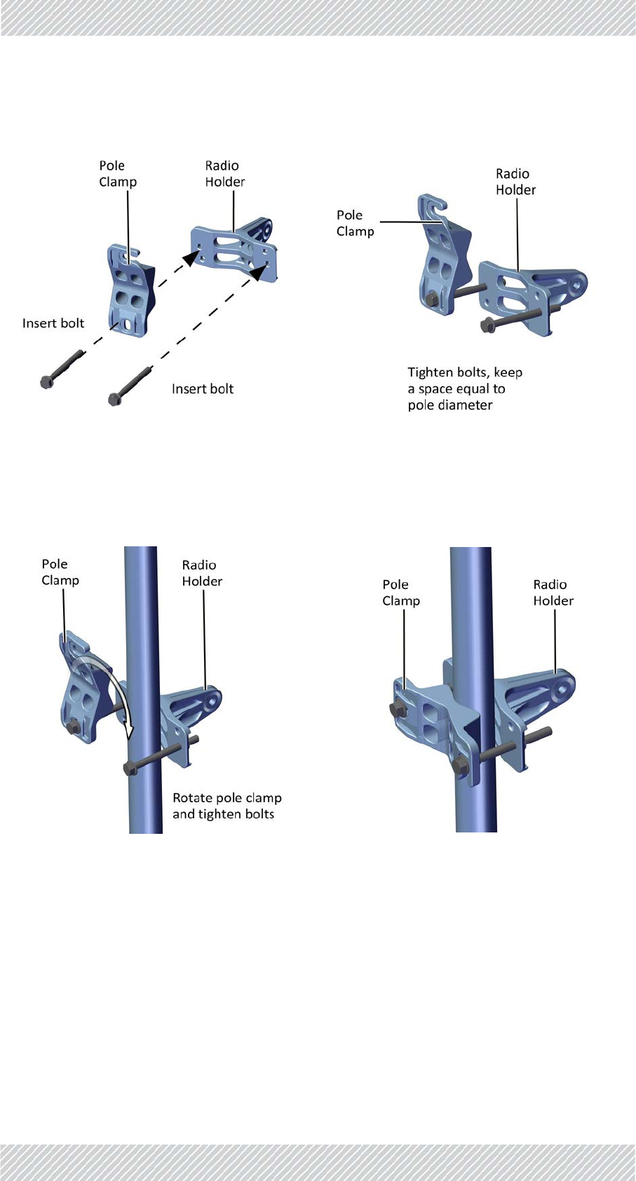
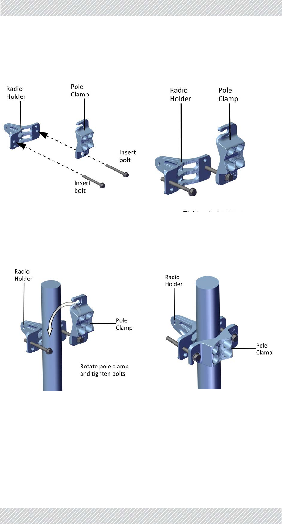
1. Whenmountingonathinpole,positionthepoleclampasshowninthefollowingfigures:
2. Placethis“unit”onthepolewhereyouwanttomounttheantenna.Onceitisin
place,rotatethepoleclampasshown,thentightenbothbolts.
MediumPole
ThismethodisformountingtheTBSantennaonapoleofpipesize2to3.
3. Connectthepoleclamptotheradioholderwiththe8x90bolts,butdonottighten
theboltsalltheway‐tightenthemsothattheyarenotcloserthanadistance
equaltotheradiusofthepole.Youwillthenhaveone“unit”thatyoucantaketo
Figure2‐36:ConnectPoleClamptoRadio
Holder
Figure2‐37:Tightenbolts
Figure2‐38:RotateClampandtightenbolts Figure2‐39:MountingKitonthinpole
FinMDeploymentGuide Release4.5.10 2‐20
TBSAntennas SiteInstallation
thelocationonthepolewhereyouwanttomounttheantenna.(SeeFigure 2‐36
toFigure 2‐39formountingonathinpole)
4. Placethis“unit”onthepolewhereyouwanttomounttheantenna.Onceitisin
place,rotatethepoleclampasshown,thentightenbothbolts.
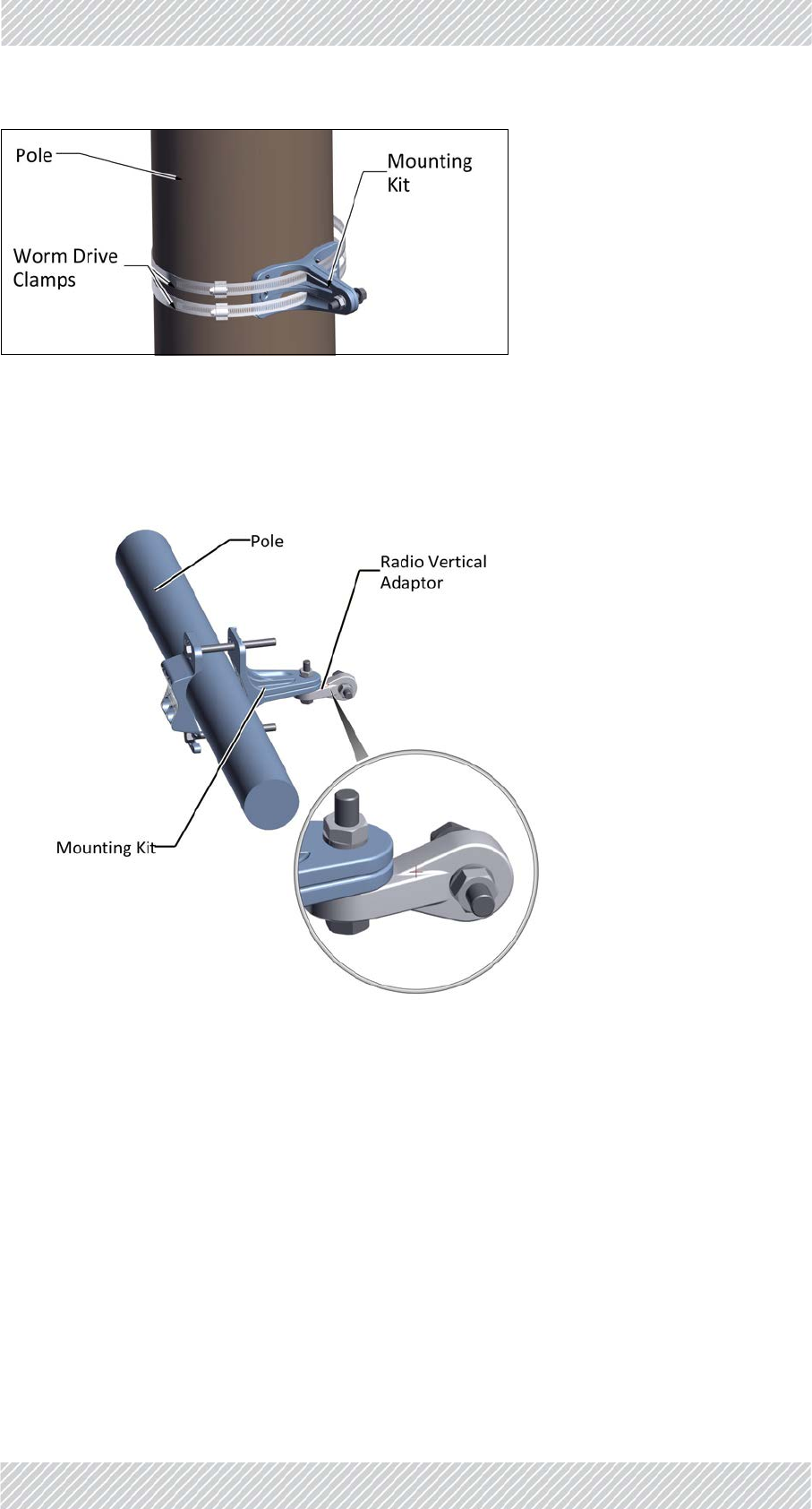
ThickPole
•ThismethodisformountingtheTBSantennaonapoleofpipesizelargerthan3.
•Usewormdriveclamps(notsupplied),threadedthroughtheholesasshown.Thepole
clampisnotneeded.
Figure2‐40:ConnectPoleClamptoRadio
Holder
Figure2‐41:Tightenbolts
Figure2‐42:RotateClampandtightenbolts Figure2‐43:MountingKitonpole
FinMDeploymentGuide Release4.5.10 2‐21
TBSAntennas SiteInstallation
Figure2‐44:Mountingkitonathickpole
TBSAntennaMountingonaHorizontalPole
Whenusingthemountingkitonahorizontalpole,usetheradioverticaladaptor,asshown:
Figure2‐45:Mountingkitonahorizontalpole
FinMDeploymentGuide Release4.5.10 2‐22
TBSAntennas SiteInstallation
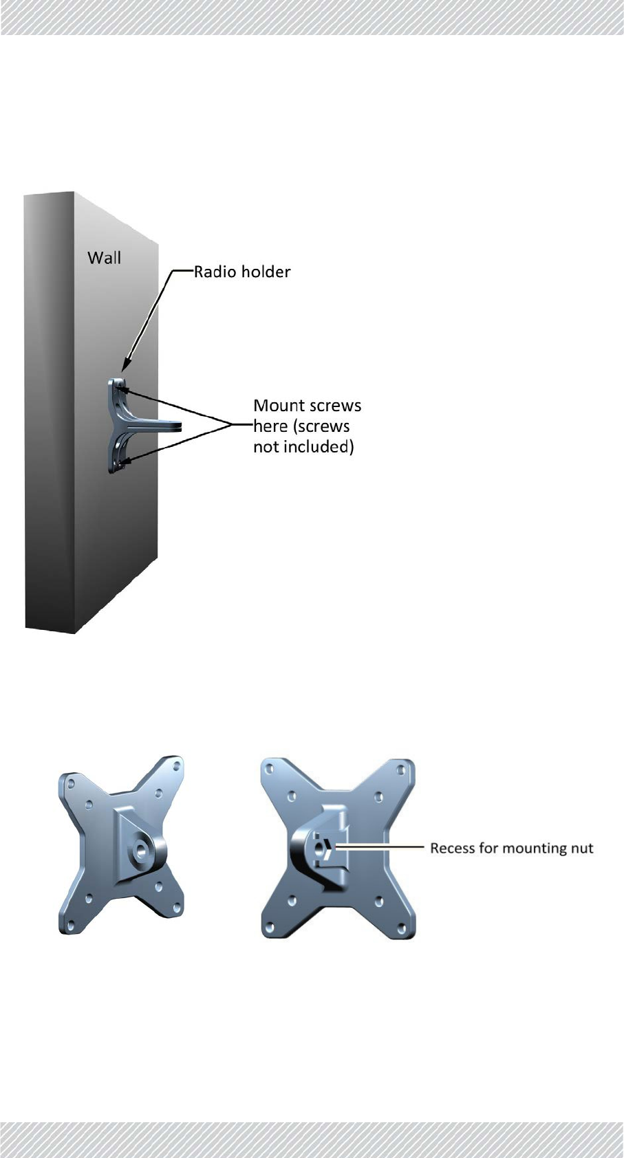
TBSAntennaMountingonaWall
Whenusingthemountingkitonawall,thepoleclampisnotnecessary:
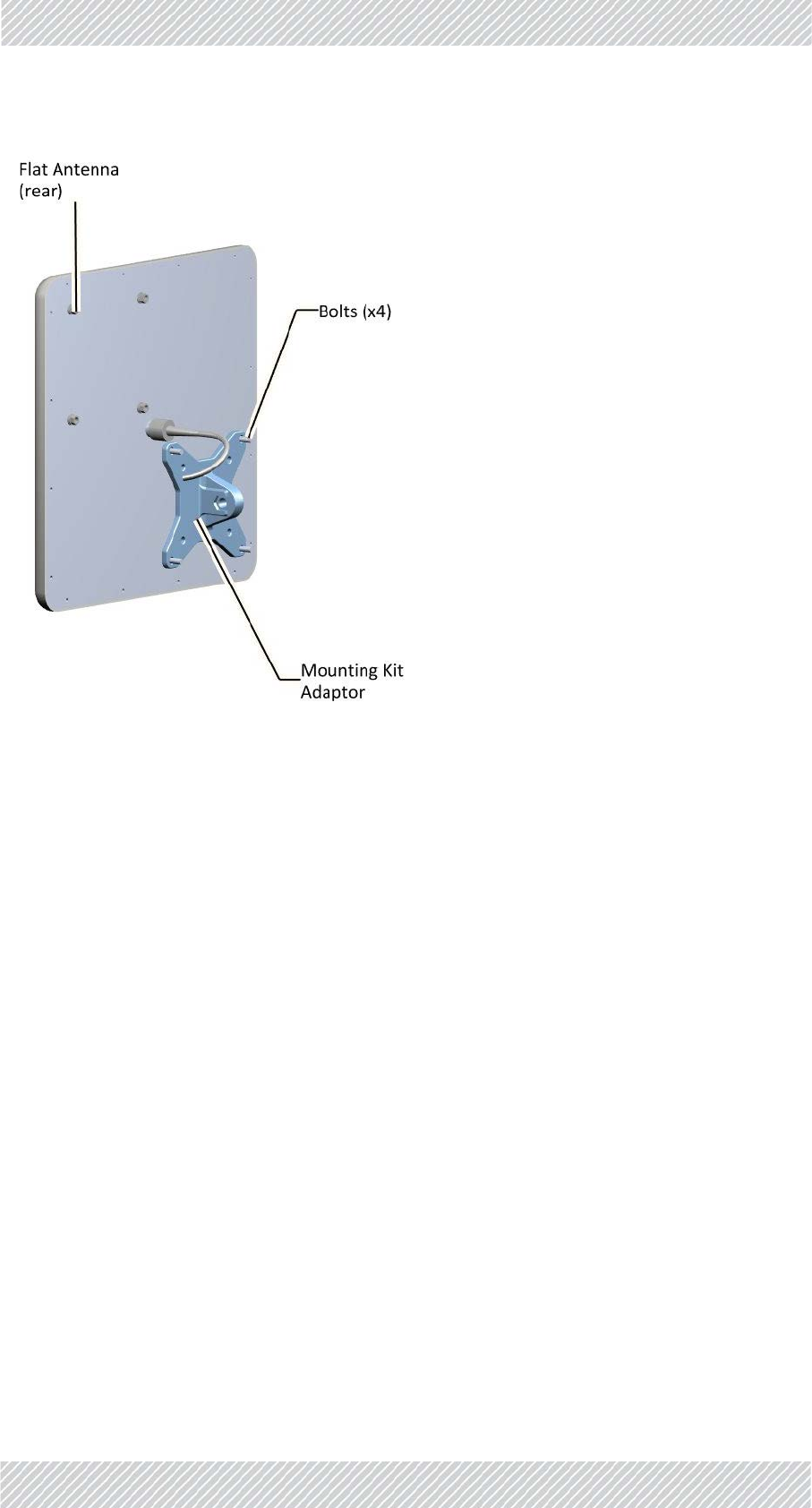
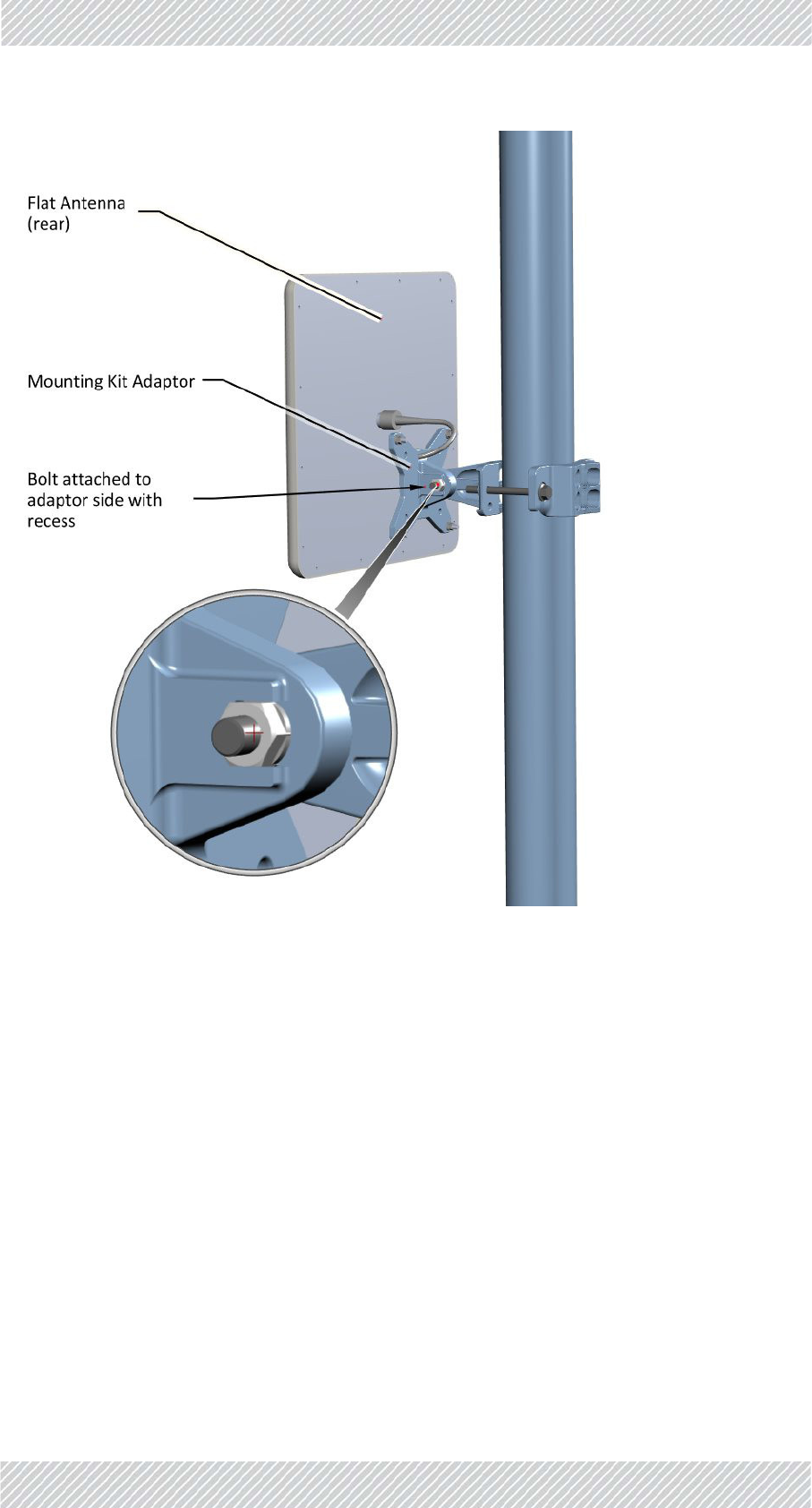
TBSAntennaMountingKitAdaptor
AflatpanelantennasuchasthatshowninFigure 2‐47istypicallyused.Ithasfourboltsfora
mountingkitadapter.ThemountingkitadaptorappearsasshowninFigure 2‐46:
Figure2‐46:Flatpanelantennamountingkitadapter
Attachthemountingkitadaptortotherearoftheantennaasshown:
FinMDeploymentGuide Release4.5.10 2‐24
TBSAntennas SiteInstallation
Figure2‐48:FlatPanelantenna‐mountedonapole
FinMDeploymentGuide Release4.5.10 2‐25
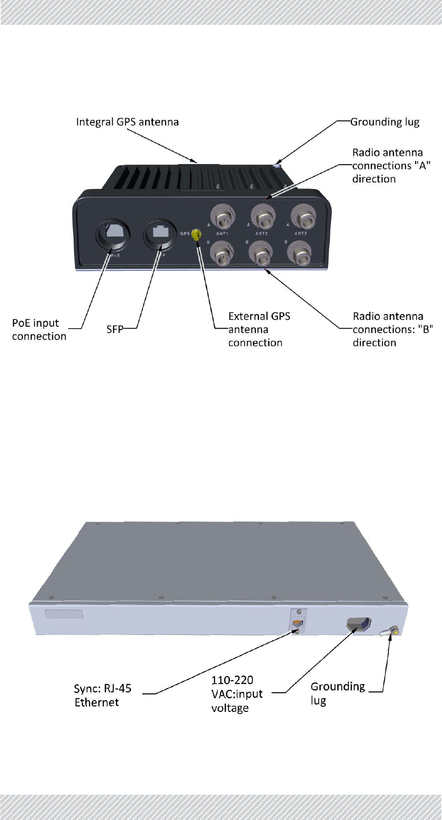
TBSExternalConnections SiteInstallation
2.2.5TBSExternalConnections
Figure2‐49:TBSexternalconnections
2.2.6SynchronizationUnits
IndoorSynchronizationUnit(ISU)
TheIndoorSynchronizationUnit(ISU)providesamastersynchronizationclockforallTBS
units,andisconnectedtooneofthenetworkswitches.
Itcanbeinstalledona19in.rackoronaconvenientindoorsurface.
Figure2‐50:IndoorSynchronizationUnit(ISU)
FinMDeploymentGuide Release4.5.10 2‐26
SynchronizationUnits SiteInstallation
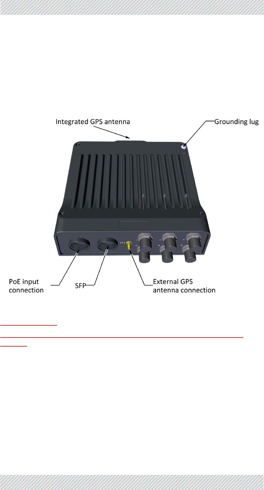
OutdoorSynchronizationUnit(OSU)
TheOutdoorSynchronizationUnit(OSU)providesamastersynchronizationclockforallTBS
units,andisconnectedtooneofthenetworkswitches.
ItishousedinthesamehousingasaTBSunit,andisinstalledinthesamemannerasaTBS
(seeTBSMountingonpage 2‐4).ItreceivesaGPSsynchronizationsignal,andcanuseits
integratedGPSantenna,oranexternalGPSantenna.
Figure2‐51:OSUexternalconnections
showaOSUoutside
showanOSUinatunnel,withawiregoingupthroughanairshafttoanexternalGPS
antenna.

FinMDeploymentGuide Release4.5.10 2‐27
ExternalGPSAntenna SiteInstallation
2.2.7ExternalGPSAntenna
TheexternalGPSantennaismountedonaverticalorhorizontalpolesegment.Figure 2‐52
showstheGPSantenna.TheantennaisseatedinaninvertedLplatewithaholeforthe
antennaport.TheLplateisstrappedtothepolewithapairofwormdriveclamps..
Figure2‐52:GPSantenna
FinMDeploymentGuide Release4.5.10 2‐28
LightningProtectionUnit(LPU) SiteInstallation
2.2.8LightningProtectionUnit(LPU)
Theuseoflightningprotectionisdependentonregulatoryandenduserrequirements.
AlthoughFinMunitshavesurgelimitingcircuitsthatminimizetheriskofdamagedueto
lightningstrikes,RADWINrecommendstheuseofadditionalsurgearrestordevicestoprotect
theequipmentfromnearbylightningstrikes.
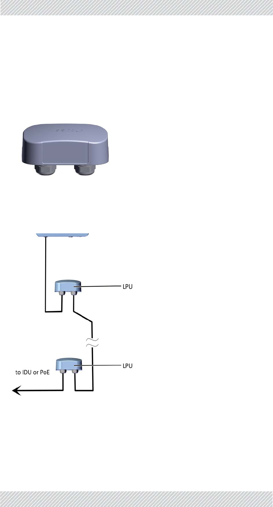
Figure2‐53:LightningProtectionUnit(LPU)
Foranytypeofindoorunit‐outdoorunitconnection,theLPUsareinstalledinpairs,asshown
inFigure 2‐54:
Figure2‐54:Basicuseoflightningprotectorunits
FinMDeploymentGuide Release4.5.10 2‐29
LightningProtectionUnit(LPU) SiteInstallation
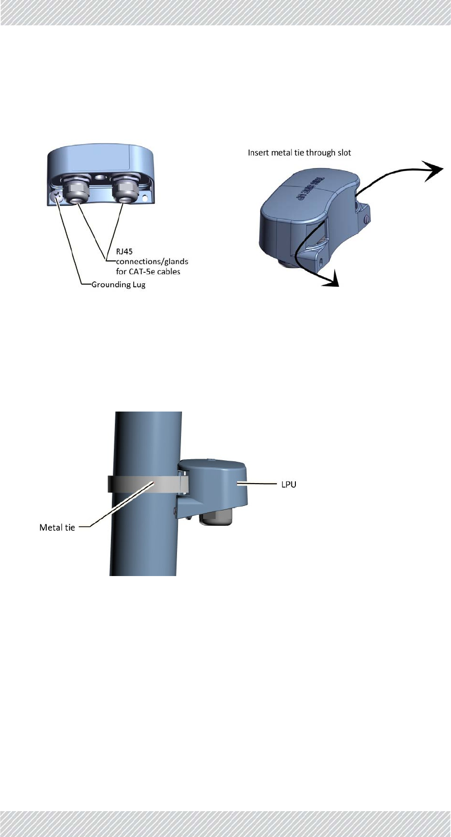
TheLPUhastwocableglandsonthebottomforCAT‐5e/6cables,inadditiontoagrounding
lug.Thereisanextraholeforasecondscrewwheninstalledonawall.OnthesideoftheLPU
isaslotforthemetaltiewheninstalledonapole,asshowninFigure 2‐55andFigure 2‐56:
ToinstallanLPUonapole:
1.Choosealocationascloseaspossibletotheradiounit.
2. InsertthemetaltiethroughtheslotsasshowninFigure 2‐56.MakesuretheLPUis
orientedinthecorrectdirection,asshowninFigure 2‐57.
Figure2‐57:LPUattachedtopolewithmetaltie
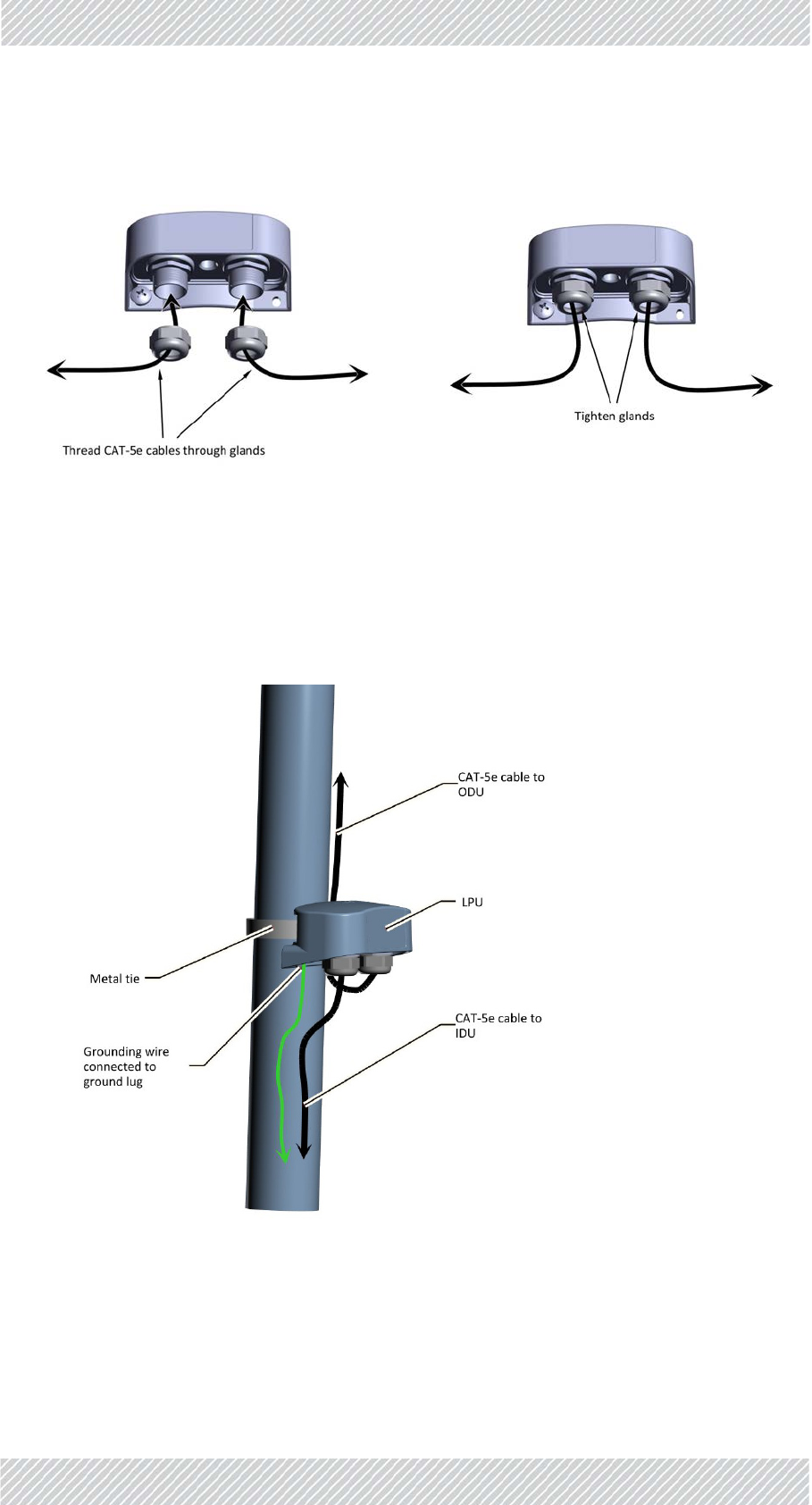
3. Tightenthemetaltie.
4. Connectthegroundinglugtoagroundingsource.
5. Removethecableglands.
6. ThreadtheCAT‐5e/6cablesthroughthecableglands,andconnectthecablestothe
LPUasshowninFigure 2‐58.
Figure2‐55:LPU:BottomView Figure2‐56:LPU:SideView
FinMDeploymentGuide Release4.5.10 2‐30
LightningProtectionUnit(LPU) SiteInstallation
7. TightenthecableglandsaroundtheCAT‐5ecablesasshowninFigure 2‐59.
8. RouteoneCAT‐5e/6uptotheradio,andtheotherdowntotheIDUorPoE(viathe
lowerLPU).AnLPUinstalledonapoleisshowninFigure 2‐60.
9. RADWINrecommendsthatyouaddextrawaterproofingtotheconnections
(seesee"Waterproofing"onpage2‐31.).
Figure2‐60:InstallinganLPUonapole(sideview)
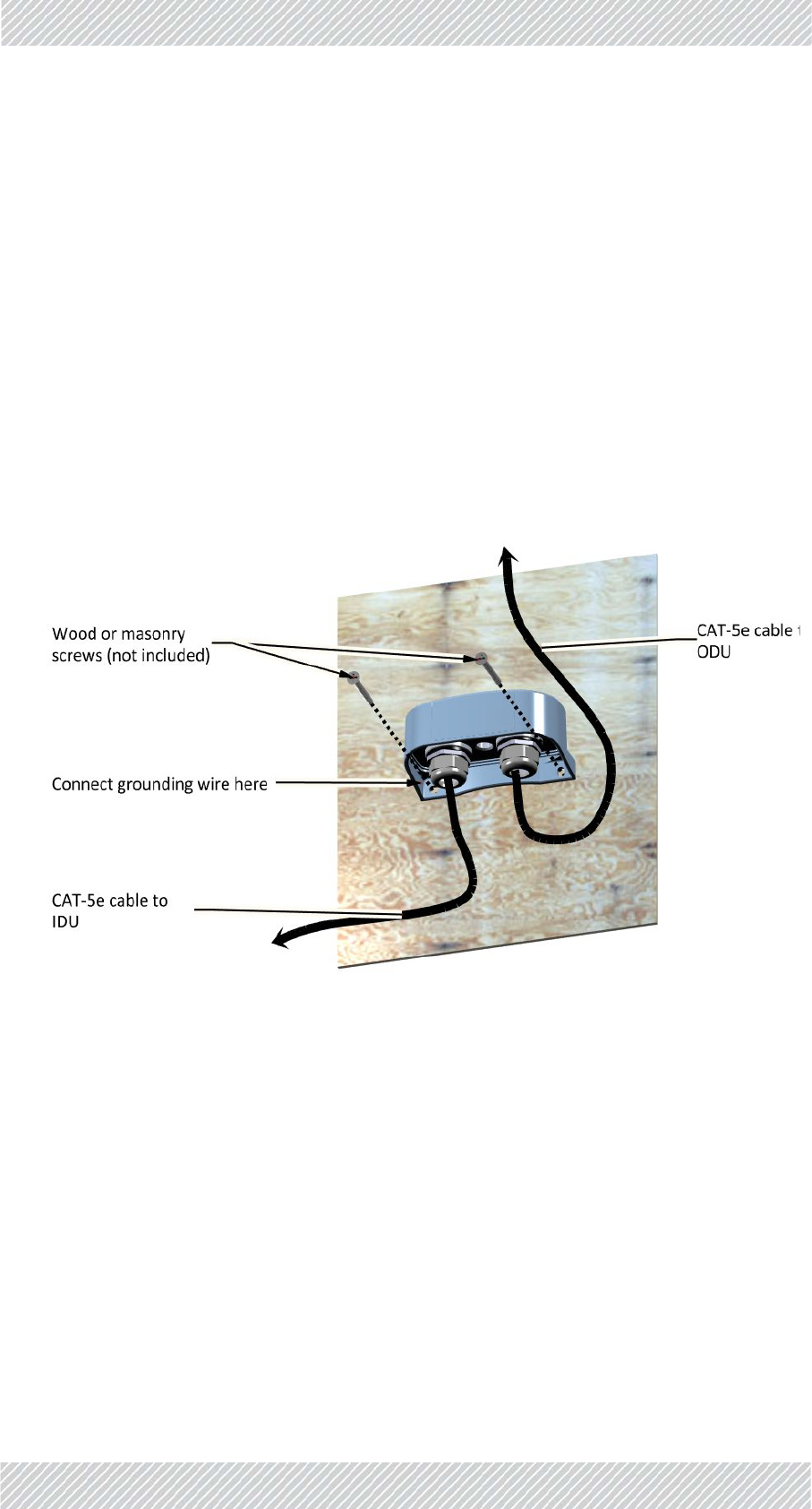
ToinstallanLPUonawall:
1.Removethegroundinglug.
Figure2‐58:ConnectingcablestotheLPU(1) Figure2‐59:ConnectingcablestotheLPU(2)
FinMDeploymentGuide Release4.5.10 2‐31
Waterproofing SiteInstallation
2. AttachtheLPUtothewallusingwoodormasonryscrews(notincluded),viathe
holesasshowninFigure 2‐61.
3. Connecttheleftscrew(wherethegroundinglugwaslocated)toagroundsource.
4. Removethecableglands.
5. ThreadtheCAT‐5e/6cablesthroughthecableglands,andconnectthecablestothe
LPUasshowninFigure 2‐58.
6. TightenthecableglandsaroundtheCAT‐5e/6cablesasshowninFigure 2‐59.
7. RouteoneCAT‐5euptotheradio(viatheupperLPU),andtheothertotheIDUor
PoE.
8. RADWINrecommendsthatyouaddextrawaterproofingtotheconnections
(seeseeWaterproofingonpage 2‐31).
Figure2‐61:InstallinganLPUonawall
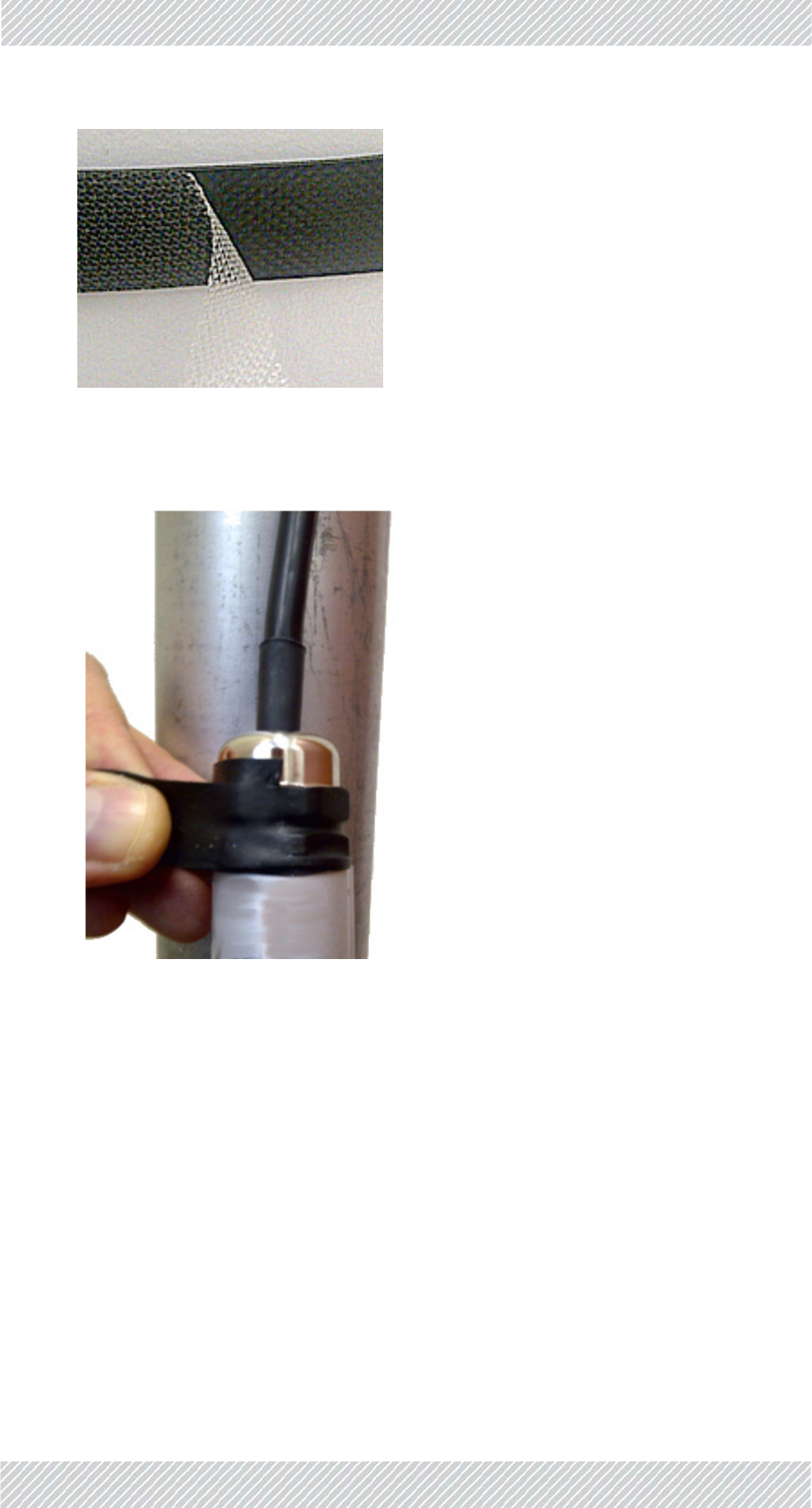
2.2.9Waterproofing
Protectallconnectionsbetweenanyoutdoordevicesandcablesfromrain,dust,moisture
andsaltaccordingtotheprocedurebelow:
1.UseahighqualitysealingmaterialsuchasScotch23Tape¾”wide,toensureIP‐67
compliantprotectionagainstwateranddust.
2. Cuttwopieceseach25cmlong,ofScotch23splicingtape.Removetheplastic
covertoexposethetackysideofthesealingtapeasshowninFigure 2‐62.
FinMDeploymentGuide Release4.5.10 2‐32
On‐Surfacevs.Skyline/ElevatedTrain SiteInstallation
Figure2‐62:Exposingthetackysideofthesealingtape
3. Afterconnectingacabletoaunit,tightenthecableglandcapfirmlyandusethe
insulationtapetofullycoverthecablegland.
Figure2‐63:Waterproofinganexternalconnection
2.2.10On‐Surfacevs.Skyline/ElevatedTrain
TBS
•Height
•Power
RADWINPoE
•PoE3rdSwitches
•Connectors
Antennas
•2X2
‐ Type

FinMDeploymentGuide Release4.5.10 2‐33
TrackSide‐BelowGround SiteInstallation
‐ Spacing
‐ Alignment
•3X3
‐ Type
‐ Spacing
‐ Alignment
Synchronization
•GSU(partoftheTBS)
•
2.3TrackSide‐BelowGround
Showmainlythedifferencesbetweenaboveandbelowground:
2.3.1TBS
MountingKit
Connectors
2.3.2Antennas
2X2
•Type
•Spacing
•Alignment
3X3
•Type
•Spacing
•Alignment

FinMDeploymentGuide Release4.5.10 2‐34
Synchronization SiteInstallation
2.3.3Synchronization
ISU
GPS
2.4TrackSide‐CombinedAboveandBelow
GroundRoute
Synchronization
ISU
GPS
CombinedGPSandISUsynchronization
2.5On‐board
2.5.1Overview
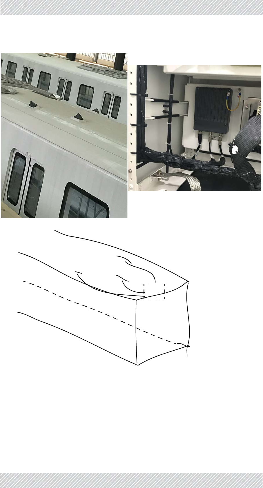
TheFiberinMotionsolutionusessharkfinantennasforitsmobileunits,andrelieson
antennaorientationtodifferentiatetheradiostreamsenoughsoastoenableMIMO.
GeneralGuidelines
•Locatetheantennasontheroofofthelocomotive,ascloseaspossibletothe
front/backend.
•PlacetheTMUascloseaspossibletotheantennas.
Power
•UsethePoEtosupplypowertotheTMU
•UsethePoEortheSFPfiberconnectiontoprovideaserviceconnectiontothe
TMU.
FinMDeploymentGuide Release4.5.10 2‐35
GeneralSet‐UpofTMUsandAntennas SiteInstallation
GeneralMountingArrangement
TheTMUcanbemountedonashelforawall.
2.5.2GeneralSet‐UpofTMUsandAntennas
FinMDeploymentGuide Release4.5.10 2‐36
TMUMounting SiteInstallation
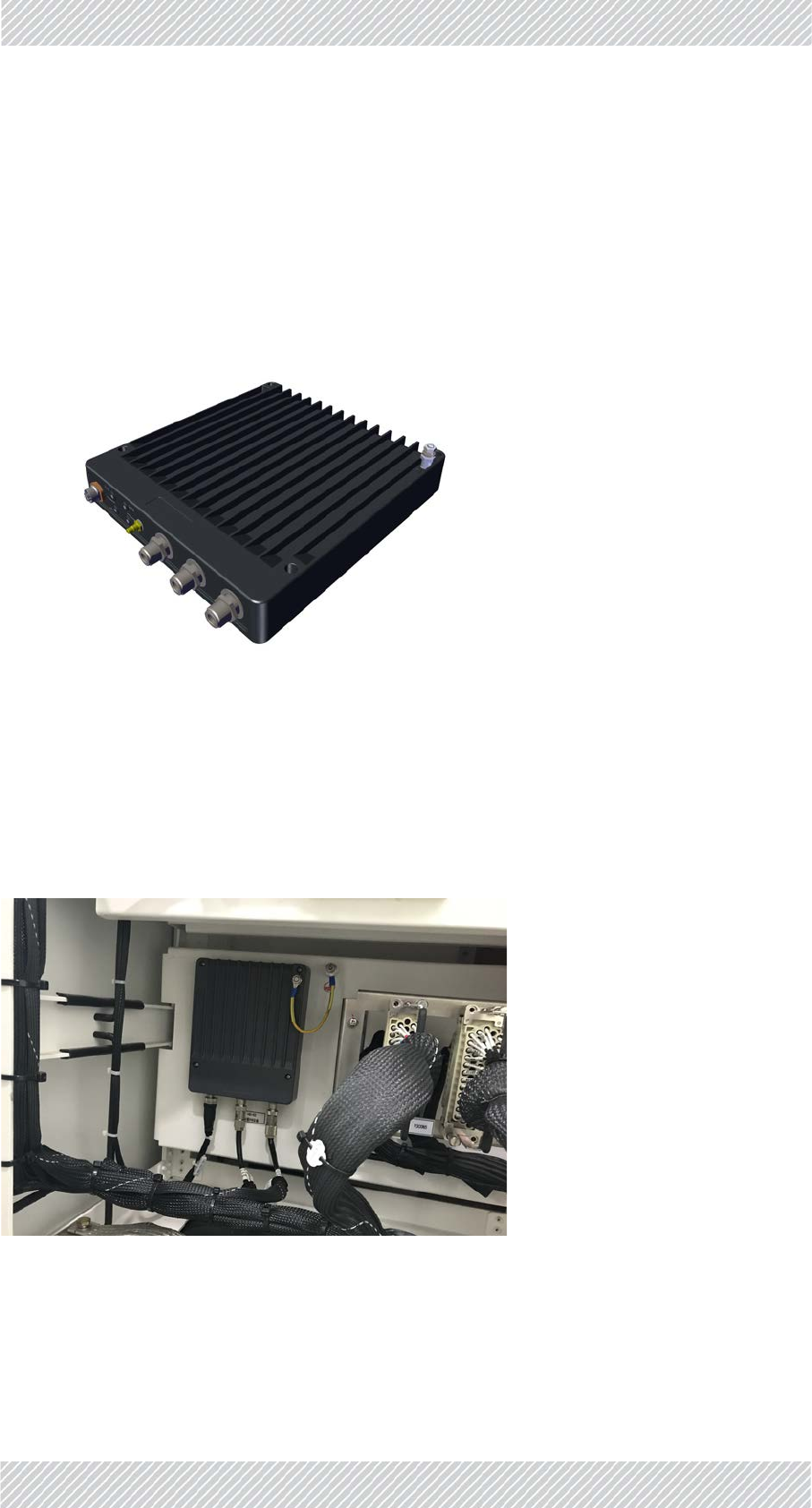
2.5.3TMUMounting
TheTMUcanbemountedina19inrack,onashelf,oronawall.Whenmountingona19in
rack,usethespecially‐designedTMU‐PoEdrawer.
TMUmountingonashelf
TheTMUcanbeplacedinanyconvenienthorizontalsurface,suchasashelf.Fastentheunit
anditsPoEproperly.
Figure2‐64:TMUmountedonashelf
TMUmountingonawall
TheTMUcanbemountedanawallwithpropersupport.Usethemountingholesand
customer‐suppliedscrewstofastentheunittoawall.MakesureyoulocateitsPoEcloseto
theunit,andfastenitproperlyaswell.

FinMDeploymentGuide Release4.5.10 2‐37
TMUMounting SiteInstallation
TMUmountingusingtheTMU‐PoEdrawer
TheTMU‐PoEdrawerisusedtomountboththeTMUandthePoEtogether.Carryoutthe
followingstepstomountbothunits:
1. ChooseasitefortheTMU‐PoEdrawerascloseaspossibletotheon‐boardantennasand
on‐boardpowersupply.Makesurethereisatleast12cm/5inofrackspace.
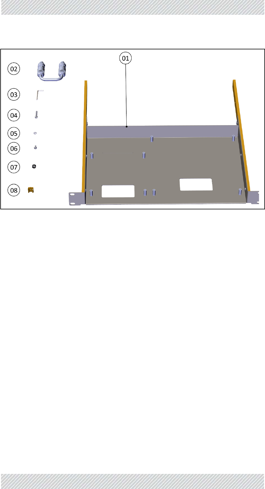
2. Openthepackage,removetheTMU‐PoEdrawerfromthepackingstyrofoam,and
cutanddiscardthetwoblackstrapsholdingthemountingslidesinplace.
3. Checkthecontents:
Table2‐3:TMU‐PoEdrawerpackagecontents
Item
No. Description Quantity
1Tray 1
2DC‐TMUJumpercable 1
3Allenwrench(M4) 1
4Allenscrews(M4x22) 8
5SpringwashersforAllenscrews 8
6DINscrews(M5x16) 12
7BlackfinishingwashersforM5screws12
8Mechanicalcage/nutsforM5screws 12
FinMDeploymentGuide Release4.5.10 2‐38
TMUMounting SiteInstallation
Figure2‐65:TMU‐PoEdrawercontents
FinMDeploymentGuide Release4.5.10 2‐39
TMUMounting SiteInstallation
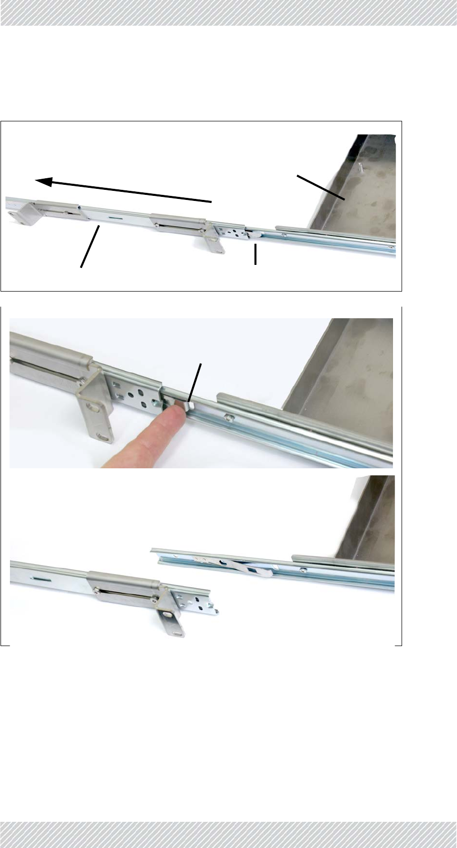
4. DetachthemountingslidesfromtheTMU‐PoEdrawer:Pulleachslideoutuntilit
isstoppedbythelockinglever.Pressthelockinglevertoreleasetheslide,andpull
slideoutcompletely.
Figure2‐66:RemovethemountingslidesfromtheTMU‐PoEdrawer.
Mountingslide
Drawer
LockingLever
Pullslide
PressLockingLever
toreleaseslide
Removeslide
FinMDeploymentGuide Release4.5.10 2‐40
TMUMounting SiteInstallation
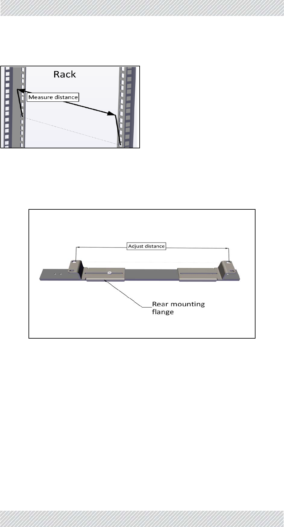
5. Measurethedistancebetweenverticalrailsoftherack.
Figure2‐67:Measuredistancebetweenverticalrails
6. Adjustthelocationoftherearmountingflangeofthefirstmountingslidesothat
thedistancebetweentheholesofthemountingflangesarethesameasthe
distanceyoumeasuredinthepreviousstep.
Figure2‐68:Adjustdistanceofrearmountingflange
FinMDeploymentGuide Release4.5.10 2‐41
TMUMounting SiteInstallation
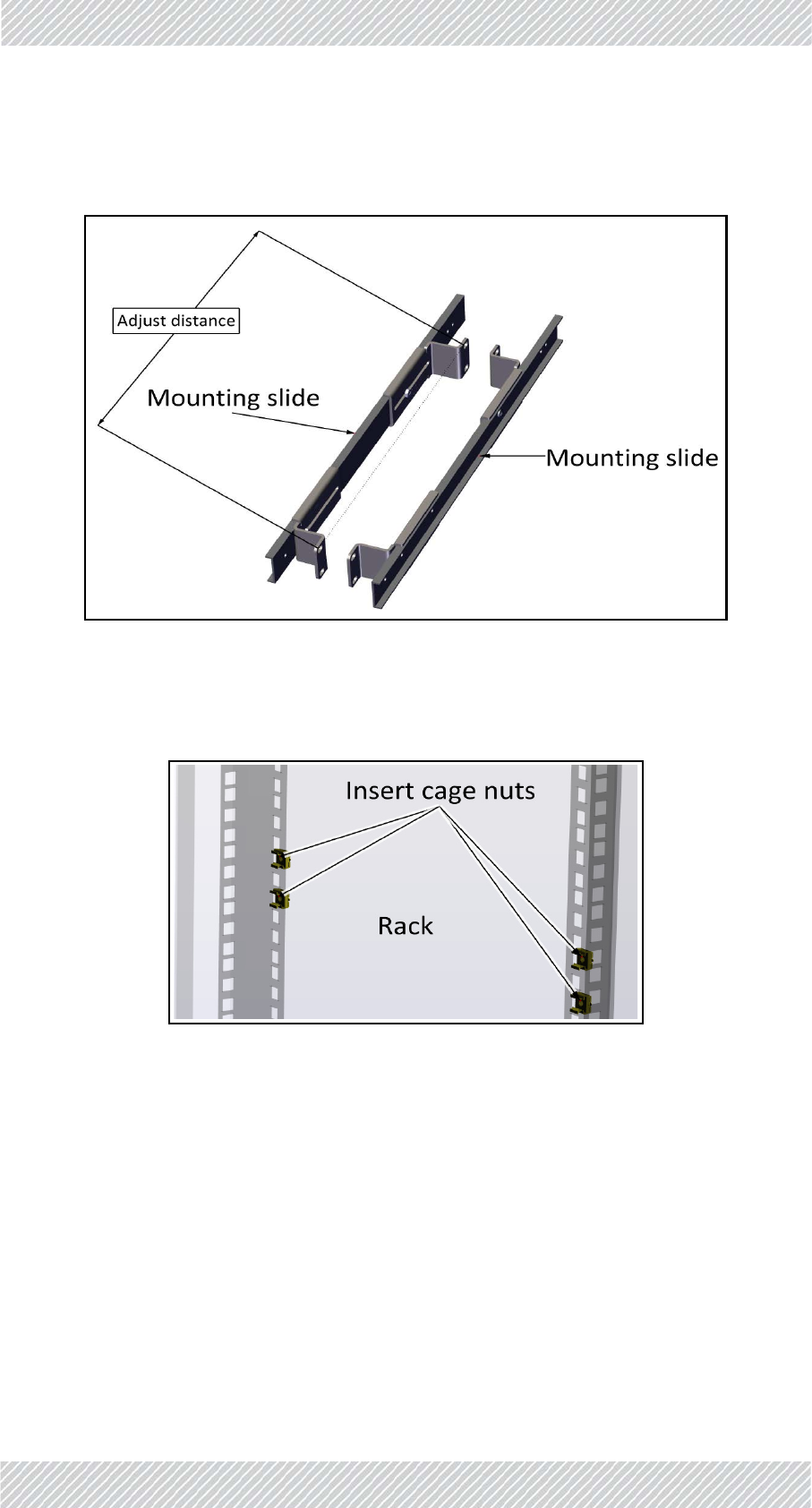
7. Placethesecondslidenexttothefirstandadjustitsrearmountingflangesothat
thedistancebetweentheflangesarethesameasthatofthefirstslide.
Figure2‐69:Adjustdistanceofmountingflangeonsecondslide
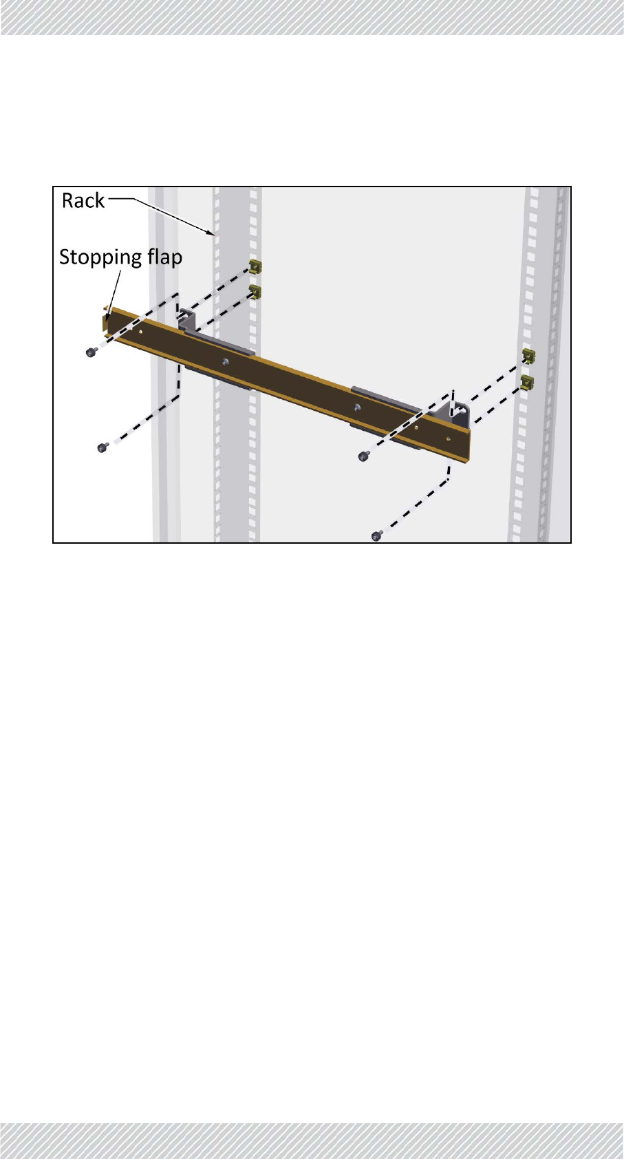
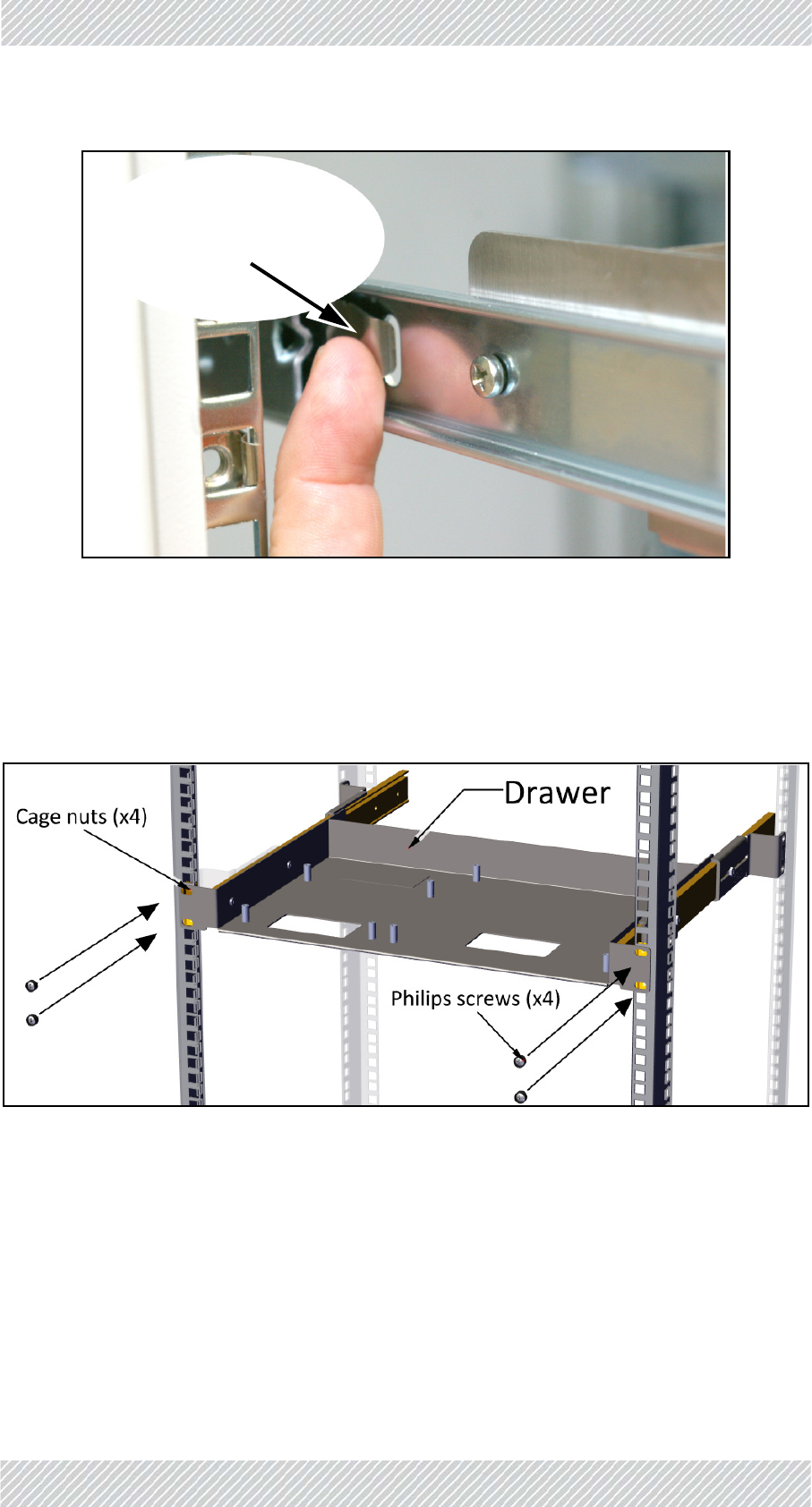
8. Insert8mechanicalcagenutsintheappropriateholesinthe19inrack:4oneach
sideoftherack.
Figure2‐70:Insertingcagenuts(onesideshown)
FinMDeploymentGuide Release4.5.10 2‐42
TMUMounting SiteInstallation
9. Placeeachmountingslidewiththestoppingflaptowardstherearoftherack,and
usingthePhilipsscrewswiththeblackwashers,fastenthemountingslidestothe
cagenutsandtighten.
Figure2‐71:Placingandfasteningmountingslide
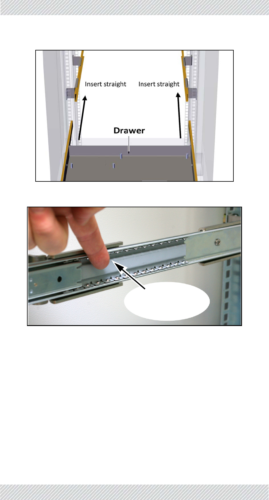
10.Oncebothmountingslidesarefastenedtightlyontherack,insertthedraweras
follows:
a. Placetheframeworkarmsofthedrawerintothemountingslidescarefully.Make
suretheyarestraight.
b. Pushbackthedraweruntiltheframeworkarmstouchtheball‐bearinggrey
housing.
c. Whilepressingoutwardsonbothball‐bearinggreyhousings,pushthedrawerin
furtheruntiltheframeworkarmsengagetheball‐bearinghousings.
d. Furtherpushthedraweruntilthelockingleverstopsit.
e. Releasethelockinglevers,andpushthedrawerinalltheway,eventhroughsome
resistancetowardstheend.
FinMDeploymentGuide Release4.5.10 2‐43
TMUMounting SiteInstallation
Figure2‐72:Insertingthedrawer:Placearmsstraight
Figure2‐73:Insertingthedrawer:Pushball‐bearinghousingsoutwards
Pushball‐bearing
housingoutwards
FinMDeploymentGuide Release4.5.10 2‐44
TMUMounting SiteInstallation
Figure2‐74:Insertingthedrawer:Releaselockinglevers
11.Inserttheother4cagenutsintheappropriateholesinthefrontsideofthe
verticalrails.
12.Usingtheother4Philipsscrewswiththeblackwashers,securethedrawertothe
frontsideoftheverticalrailsoftherack.
Figure2‐75:Securedrawertothefrontsideofrack
Presslockinglevers
andpushdrawerin
FinMDeploymentGuide Release4.5.10 2‐45
TMUMounting SiteInstallation
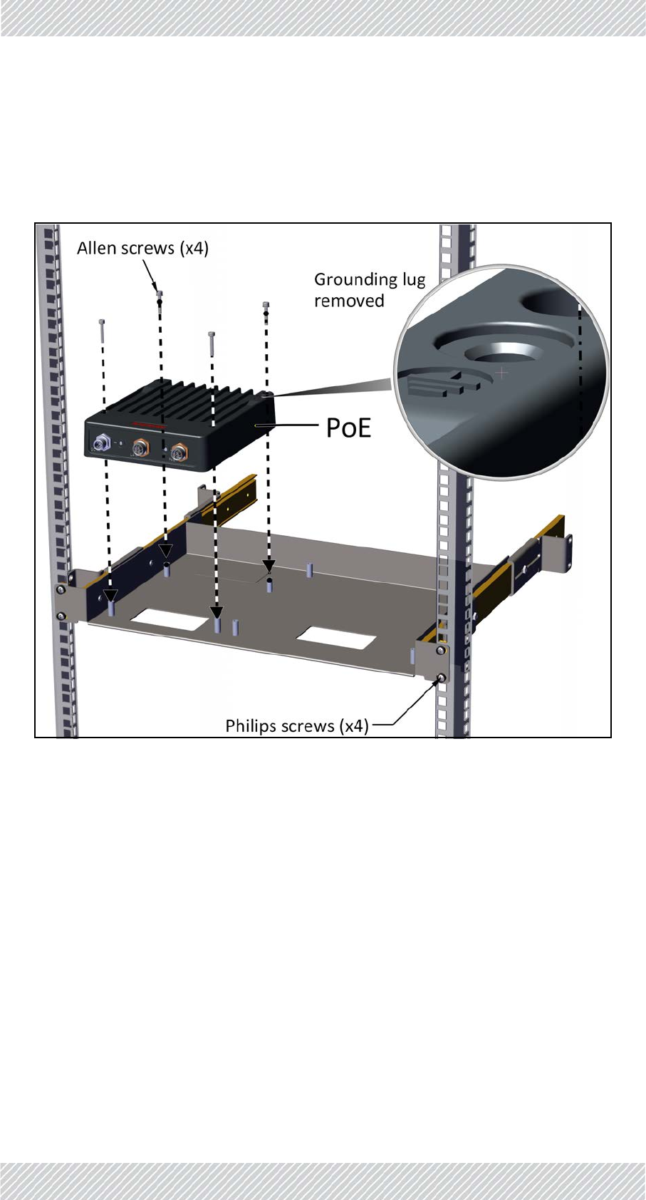
13.AttachPoEandTMUtodrawerasfollows:
a. Removegroundinglugsfrombothunits(theyinterferewiththedrawerandarenot
neededforadrawerinstallation).
b. PlacePoEoverthepinsoftheleftsideofthedrawerasshown,andattachusing
allenscrews.
Figure2‐76:AttachingPoEtodrawer
FinMDeploymentGuide Release4.5.10 2‐46
PoEDevicesfortheTMU SiteInstallation
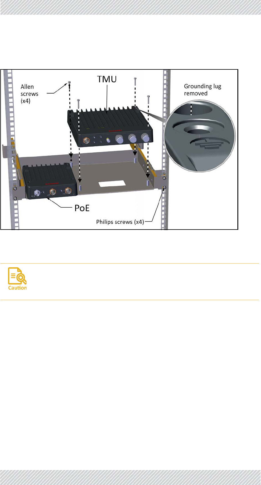
c. PlaceTMUoverthepinsontherightsideofthedrawerasshown,andattachusing
allenscrews.
Figure2‐77:AttachingTMUtodrawer
2.5.4PoEDevicesfortheTMU
TheDCPoEdeviceisalwaysmountednexttotheTMU.
Theunitscanbemountedina19inrack,ashelf,oronawal.
MountingwiththeTMU‐PoEdrawer
TheTMU‐PoEdrawerisusedtomountboththeTMUandthePoE.Followtheinstructionsin
“Mountingonawall”onpage2‐45.
MountingonaDINrack
ThePoEcanbemountedonaDINrack.CarryoutthefollowingstepstomountthePoEona
DINrack:
TheTMUandPoE,whenmountedintheTMU‐PoEdrawer,aregroundedviathe
mountingpins,throughthe19inrack.
Makesuretherackyouareusingisgroundedproperly.

FinMDeploymentGuide Release4.5.10 2‐47
TMUAntennas SiteInstallation
Figure2‐78:AttachingaDINrackholdertothePoE
Figure2‐79:AttachingaPoEtoaDINrack
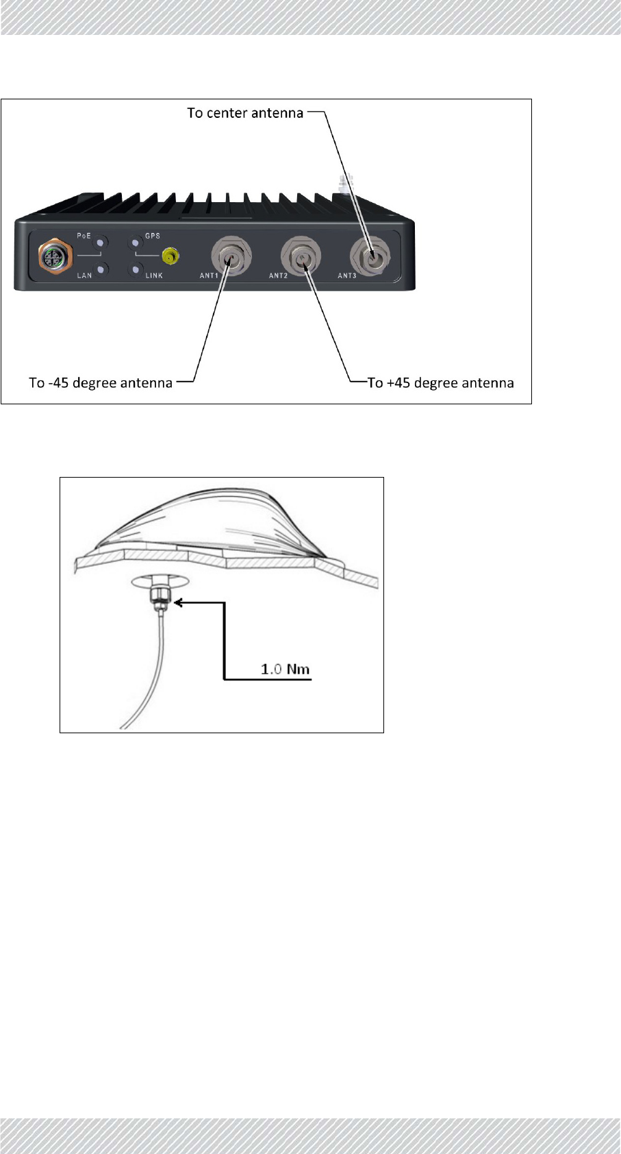
2.5.5TMUAntennas
EachTMUneedsthree“Shark‐Fin”roofantennasmountedontheroofofthelocomotive
ascloseaspossibletotheTMU:
Figure2‐80:“Shark‐Fin”antenna‐bottomview
Whatevermountingarrangementisadopted:
•TheantennasshouldbemountedasclosetotheTMUaspossible.
•Trytominimizeobstructionsbetweentheantennasandthefrontofthetrainsuchas
air‐conditionerunits,electronicroutenumberdisplayboxesandthelike.
FinMDeploymentGuide Release4.5.10 2‐48
TMUAntennas SiteInstallation
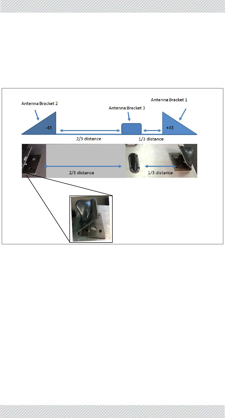
•MountAntenna1andAntenna2ontheedgeofthelocomotiveata45oangle,as
showninFigure 2‐81.
•MountAntenna3(center)ata90oangle(directlyup)andonethirdofthedistance
betweentherightandleftantennasasshowninFigure 2‐81.
•ConnecttheantennaportsoftheTMUtotheantennasasshowninFigure 2‐82.
Figure2‐81:TMUantennamountingconfigurationonroof
FinMDeploymentGuide Release4.5.10 2‐49
TMUAntennas SiteInstallation
Figure2‐82:TMUantennaportconnectionscheme
4.ConnecttheRFcableasshownbelow:
FinMDeploymentGuide Release4.5.10 2‐50
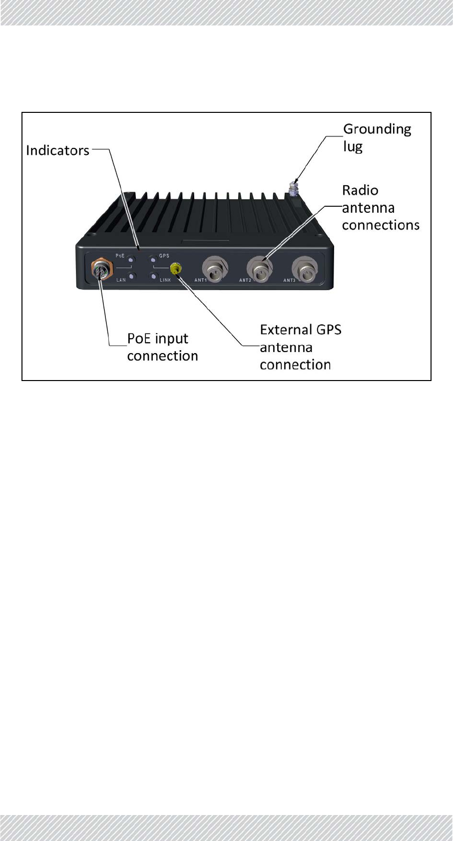
TMUExternalConnections SiteInstallation
2.5.6TMUExternalConnections
Figure2‐83:TMU‐ExternalConnections
2.6Grounding
AllRADWINproductsshouldbegroundedduringoperation.Inaddition:
•Allunitsshouldbegroundedbyawirewithdiameterofatleast10AWG.
UnitsmustbeproperlygroundedtoaProtectiveGroundinaccordancewiththeLocal
ElectricalRegulations
•Rack‐mountedequipmentshouldbemountedonlyingroundedracksandcabinets.
Further,youshould‐
•Alwaysmakethegroundconnectionfirstanddisconnectitlast
•Neverconnecttelecommunicationcablestoungroundedequipment
•Ensurethatallothercablesaredisconnectedbeforedisconnectingtheground
TBSandOSU
ThereisagroundinglugontheTBSandOSUasshowninFigure 2‐84.Grounditusing10AWG
wire.

FinMDeploymentGuide Release4.5.10 2‐52
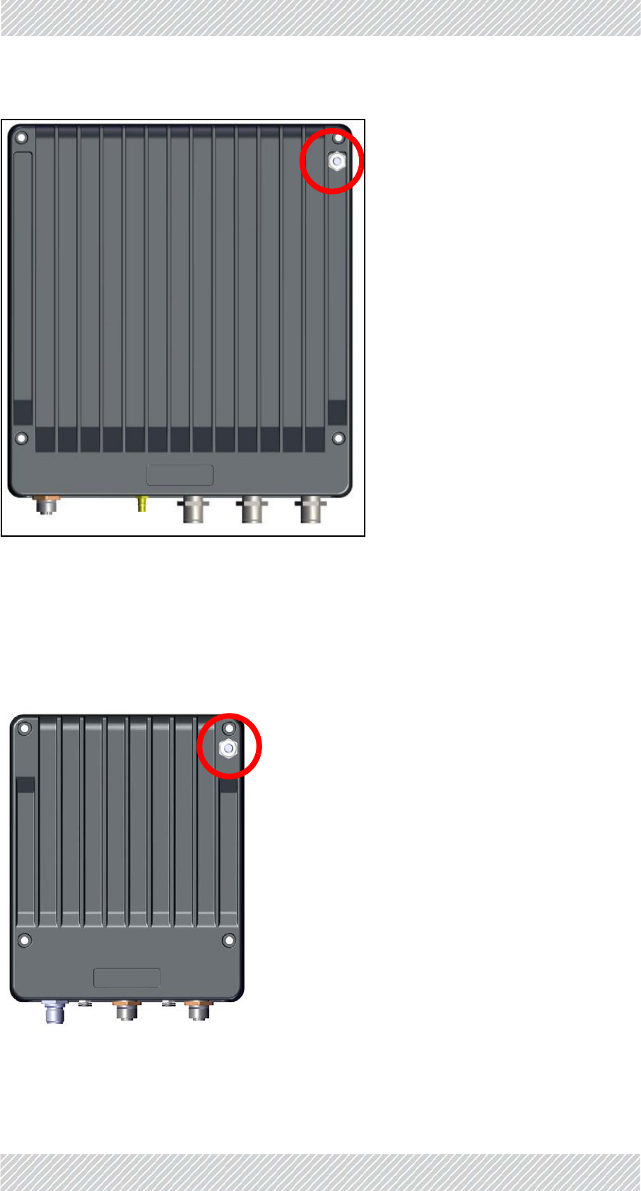
Grounding SiteInstallation
Figure2‐85:TMU:Groundingluglocation
Whenmountedina19inrack,theTMUisgroundedviatherack.
FinMPoE
ThereisagroundinglugontheFinMPoEasshowninFigure 2‐86.Grounditusing10AWG
wire.
Figure2‐86:PoE:Groundingluglocation
FinMDeploymentGuide Release4.5.10 2‐53
Grounding SiteInstallation
Whenmountedina19inrack,thePoEisgroundedviatherack.
ExternalPoE
ThereisagroundinglugontheexternalPoEasshowninFigure 2‐87.Grounditusing10AWG
wire.
Figure2‐87:PoE:Groundingluglocation
ISU
TheISUisgroundedviaitsgroundconnectiononitsfrontpanel.
Figure2‐88:ISU:Groundingluglocation
Antennas
GroundexternalantennasusingasuitableGroundingKitsuchasanAndrewType223158‐2
(http://www.commscope.com).

FinMDeploymentGuide Release4.5.10 3‐1
Chapter3:NetworkGuidelines
3.1ScopeofThisChapter
ThischapterprovidesadescriptionofthetypicalnetworkingtopologyrequiredbyRADWIN's
FiberinMotionTrain‐To‐Groundsolution.
3.2Overview
Includedinthischapterare:
•Ageneralintroductiontothenetworkrequirementsfortracksideandon‐boardnet‐
works,
•Adescriptionoftherequiredrouters'functionalities,
•Adataflowdescription,
•SampleIPandVLANassignmentguidelines,
•Ashortdescriptionoftheupdatemessagesduringhandovers,andhowtherecom‐
mendednetworktopologysupportsthesemessages.
ThetypicalnetworkingdescribedinthischapterenablesbroadbandTrain‐To‐Ground
communication,whilemaintainingahandovertimeoflessthan50ms.
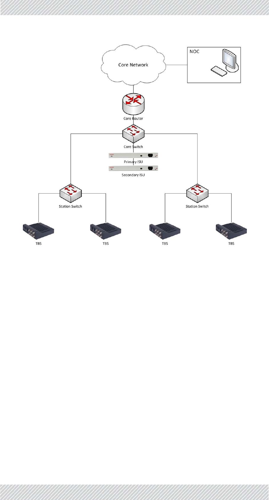
3.3WaysideNetwork
TheRADWINFiberinMotionbest‐practicesolutionisbasedonatransparentlayer2
architecture:
•ThebackhaulnetworkisconnectedtotheRadioBaseStations(TBS)deployedalongthe
trackssideviaGbEcopperorfiber,asalayer2basednetwork.
Followtheguidelinescarefully.Anyquestionsorclarificationsshouldbe
addressedtoRADWIN'sProfessionalServicesteamforanofficialresponse.
Priortoprojectrollout,adetailednetworkarchitecture(includingtopologyand
HWtobeused)shouldbesharedwithRADWINforconfirmation.

FinMDeploymentGuide Release4.5.10 3‐2
WaysideNetwork NetworkGuidelines
•Thebackhaulnetwork(existingorprovidedbythesystemintegrator/customer)isused
toaggregatetrafficto/fromtheTBSsandsendittothecontrol/datacentres.
•Therequirednetworkarchitecturemusthaveasinglecorerouter,andL2switches.All
datacommunicationto/fromthetrainwillpassviathisrouter.
•AredundantISU/OSUisprovidedtoensurehigherresiliencyofthesolution.
•TheTBS'snetworkissynchronizedeitherviaGPS‐basedsystem(forabovegroundsce‐
narios)orviaEthernet‐basedsynchronization(foraboveorundergroundscenarios).
•ForGPSbasedsynchronization,theTBSintegratedGPSSynchronizationUnitisused.
•ForEthernet‐basedsynchronization,theTBS'snetworkissynchronizedbyEthernet
basedsynchronization,runningoverthesamedatabackhaulnetwork.Theimplementa‐
tionofthesynchronizationprotocolisviaanIndoorSynchronizationUnit(ISU)orOut‐
doorSynchronizationUnit(OSU)thatisconnectedtooneofthenetworkswitches,and
providesthemasterclocktoallTBSsinthenetwork.
•ISUsworkusingastartopology,whileOSUsworkusingaringtopology.
•Thesynchronizationarchitecturemayvarydependingonthespecificnetworktopology,
soRADWINneedstoevaluateandapprovethewaysidenetworktopologyandassureit
willsupportthesynchronizationprotocol.Typicalsynchronizationrequirements
include:
•Layer2connectionbetweenallISU/OSUsandTBSs.
•Maximumof4switchesbetweenISU/OSUsandeachTBS.
•Avoidhighlinespeedutilizationtopreventintroductionofjitterandlatency.The
lineloadshouldbelimitedaccordingtothefollowingtable:
•Networkswitchesshouldappropriatelyhandlethesystem'srelearningframes.These
framesareVLANtagged(802.1Q).Switchshouldforwardtherelearningtrafficand
updateFIB(ForwardingInformationBase).
•IEEE802.3azmustbedisabledonallswitches.
•Spanningtreebetweentrainandwaysideisnotsupportedandmustbedisabledon
switchportsconnectedtotheRADWINradios(bothTBSsandTMUs).
•Staticroutingshouldbeimplementedbetweenwaysidecorerouterandon‐boardrout‐
ers.ImplementationofdynamicroutingprotocolsshouldbeconfirmedwithRADWIN
professionalservices.
Table3‐1:ISU/OSU‐TBSswitchesvs.lineutilization
NumberofSwitches
BetweenISU/OSUandTBS MaximalLineUtilization
195%
285%
3 75%
465%
FinMDeploymentGuide Release4.5.10 3‐3
On‐boardNetwork NetworkGuidelines
Figure3‐1:Typicalwaysidenetworkarrangement
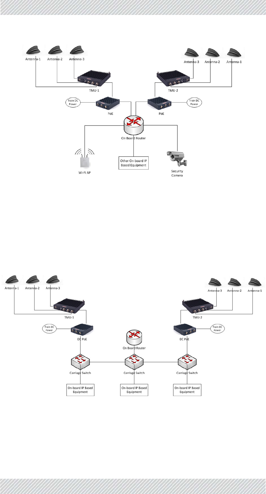
3.4On‐boardNetwork
•Ideally,aTransportationMobileradioUnit(TMU)isdeployedateachendofthetrain.It
isconnected,viaaPoE,tothetrain'sinternalnetwork(Trainnetworkisresponsibilityof
systemintegrator).L2connectivityisrequiredbetweenbothTMUs
•TMUsandtrainroutershouldbeonthesameIPsubnet
•Trainequipment(APs,CCTVcameras,PISdevicesetc.)shouldbeonadifferentsubnet
fromthatoftheTMU
•Allofthetrain'strafficissentviaanon‐boardrouter(providedbythesystemintegra‐
torI)totheactiveTMUprovidingthehighestthroughput(whichTMUisconsidered
“active”isautomaticallydeterminedbythesystem).
•Theon‐boardtrainnetworkshouldsupportVLANs
•Networkswitchesshouldappropriatelyhandlethesystem'srelearningframes.These
framesareVLANtagged(802.1Q)andswitchshouldforwardtherelearningtrafficand
updatetheFIB(ForwardingInformationBase)
•IEEE802.3azshouldbedisabledonallswitches
•Spanningtreebetweentrainandtracksideisnotsupportedandmustbedisabledon
switchportsconnectedtotheRADWINradios.
FinMDeploymentGuide Release4.5.10 3‐4
On‐boardPhysicalConnectivity NetworkGuidelines
Figure3‐2:Typicalon‐boardnetwork(logicalconnectivity)
3.5On‐boardPhysicalConnectivity
Figure 3‐3presentsanexampleofatypicalphysicalconnectivitywithinanon‐boardnetwork.
On‐boardroutermustbeconnectedthrough1physicalport,butthisportmustsupportat
least2subinterfaces(routeronastick/onearmedrouterimplementation).Eachsub
interfacemusthaveitsownIPaddressandVLANtoenabletheIPschemedetailedbelow(see
BasicIPSchemeandDataFlowPathonpage 3‐5).
Figure3‐3:Typicalon‐boardnetwork(physicalconnections)

FinMDeploymentGuide Release4.5.10 3‐5
WaysideCoreRouter NetworkGuidelines
3.6WaysideCoreRouter
ThewaysidenetworkrequiresacorerouterthatwillactasthegatewaybetweentheTrain‐
To‐Groundsystemandtheclient'scorenetwork.Alltrafficbetweenanytrain'son‐board
devicesandtheclient'scorenetworkmustpassthroughthisrouter.Thewaysidecorerouter
musthaveatleast2interfaces(seediagrambelowinSection3.7):
Interface1:Connectstotheclient'scorenetwork.Itwillbeonthesamesubnetasthe
client'snetworkandwillbethegatewayforalltrafficfromtheclientnetwork
targetedatdevicesonboardtrains.
Interface2:UsedfortheTrain‐To‐Groundnetwork.Itwillbeonthesamesubnetastheon‐
boardrouterinterface1andwillbethegatewayforalltrafficfromtheon‐
boardroutersonallthetrains.
Alltrafficbetweenanyon‐boarddeviceandthetracksidemustpassthroughtheon‐board
router.
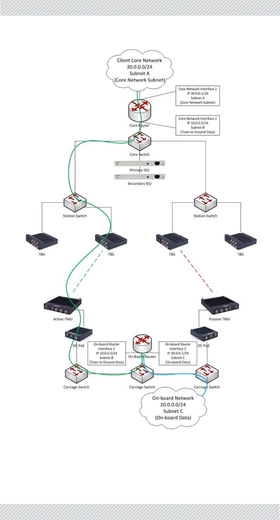
3.7BasicIPSchemeandDataFlowPath
AnexampleofthebasicIPschemeisshownhere.
Thetrafficflowsbetweenthewaysidecorerouterandtheon‐boardrouter.Allelements
betweentherouters(includingswitchesandFiberinMotionradios)arepureL2devices.They
haveanIPaddressformanagementonly,andaretransparenttothedatatraffic.
Overall,atleast3IPsubnetsarerequired:
•SubnetAfortheclientcorenetwork.
•SubnetBforthetraintogroundsegment.
•SubnetCfortheon‐boardnetwork.
IfworkingwithaVLAN,seeRecommendedVLANAssignmentonpage 3‐7.
FinMDeploymentGuide Release4.5.10 3‐6
BasicIPSchemeandDataFlowPath NetworkGuidelines
Figure3‐4:BasicIPSchemeandDataFlow

FinMDeploymentGuide Release4.5.10 3‐7
RecommendedVLANAssignment NetworkGuidelines
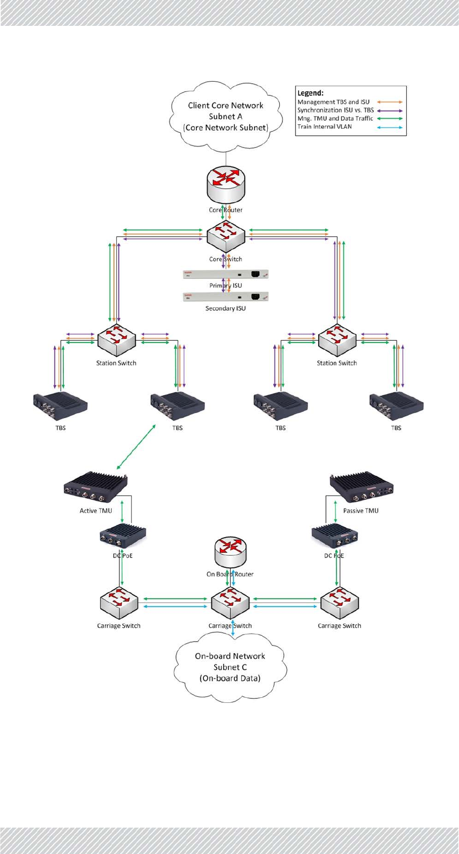
3.8RecommendedVLANAssignment
AtypicalVLANassignmentthroughoutthenetworkwouldincludethefollowing:
•VLANV1‐ForTBSandISUmanagement
•VLANV2‐Fortracksidesynchronization(BetweenISUandTBSs)
•VLANV3‐For:
•Usertraffic(betweentracksidecorerouterandon‐boardrouter)
•TMUmanagement
•Signallingbetweentwoon‐boardTMUs(tosupportintratrainhandoverindual
TMUpertraindeployment)
•VLANV4‐Trainon‐boardinternalnetwork(foralltrainenduserdevices‐enduserAPs,
IPcameras,IPphones,etc.)
FinMDeploymentGuide Release4.5.10 3‐8
RecommendedVLANAssignment NetworkGuidelines
Figure3‐5:VLANAssignment

FinMDeploymentGuide Release4.5.10 3‐9
InterBaseHandover(IBHO)UpdateMessage NetworkGuidelines
3.9InterBaseHandover(IBHO)Update
Message
FiberinMotionprovidesL2connectivity,soallL3features(routingetc.)arehandleddirectly
betweentheon‐boardrouterandthewaysidecorerouter.Theadvantageofthismodeof
operationisthatnoroutingupdatesareneededduringhandovers,facilitatingthecontinuous
fasthandoversneededasthetrainmovesalongthetrack.
However,therewillbeotherL2devices(switches)alongthewaysidenetworkthatmustbe
updated.
WhenaTMUmovesfromoneTBStothenext,theremustbeanupdateofthewayside
networksotheswitchesknowthenewdatapath.Thisupdateismadebysendinganupdate
messagetothewaysidecorerouter.However,wedonotwishtosendanupdatemessagefor
eachon‐boarddevice,asthiswilloverloadthesystem.Forthisreason,theupdateissent
regardingonly1device‐theMACaddressoftheon‐boardrouter(sincealltheon‐board
devicesarebehindit,theydonotneedtohaveindividualupdatemessagessent).
FinMDeploymentGuide Release4.5.10 3‐11
InterBaseHandover(IBHO)UpdateMessage NetworkGuidelines
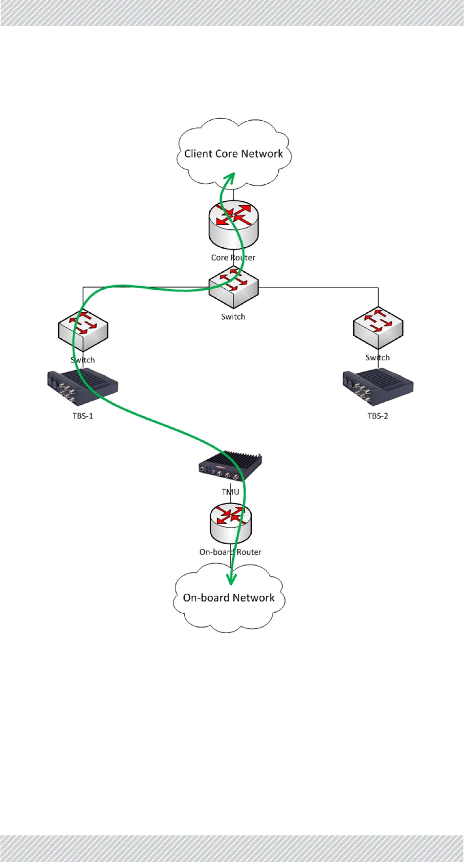
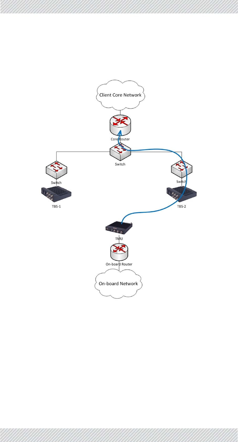
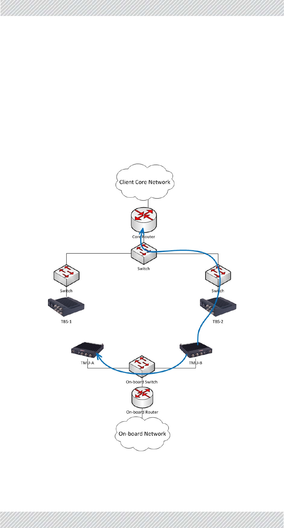
WhentheTMUhasmadeadecisiontoswitchfromTBS‐1toTBS‐2(basedonRSSthresholds)
itinitiatesanupdatemessage(showninblueinFigure 3‐7)tothewaysidecorerouter,with
thesourceMACaddressoftheon‐boardrouter.
Allswitchesalongthewaysidenetwork'snewdatapatharethenupdated.
Figure3‐7:IBHO‐Part2
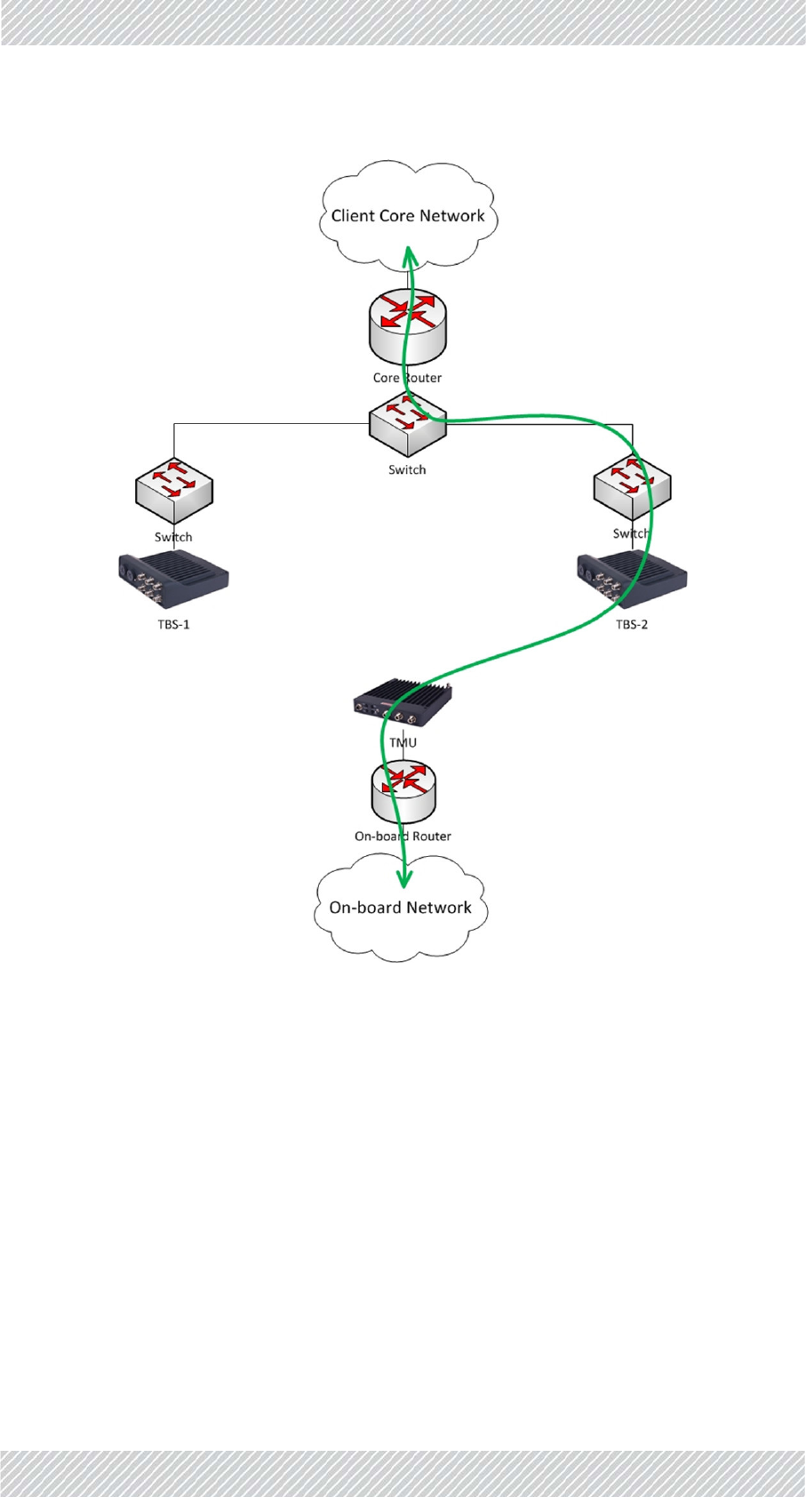
Asaresult,theTMUisconnectedtoTBS‐2andalltrafficflowsinthenewpath.
FinMDeploymentGuide Release4.5.10 3‐12
IntraTrainHandover(ITHO)UpdateMessage NetworkGuidelines
Figure3‐8:IBHO‐Part3
3.10IntraTrainHandover(ITHO)Update
Message
ParalleltotheInterBaseHandover(IBHO)process,describedabove,FiberinMotionalso
supportsanIntraTrainHandover.
TheITHOfeature,implementedintheTMUs,enablesextendedcoverageandthroughput.As
mentionedabove(seeTrainSide(On‐board)Networkonpage 2‐3)thismoderequires2on‐
boardTMUs(ideallyateachendofthetrain),withL2connectivitybetweenthem.
FinMDeploymentGuide Release4.5.10 3‐13
IntraTrainHandover(ITHO)UpdateMessage NetworkGuidelines
ThisprocesshappensinparallelandindependentlyfromtheIBHO.Thebackgroundprocess
consistsofacontinuousevaluationbetweenthe2on‐boardTMUs,astowhichcanreceive
thehigherthroughput(regardlessofwhichbasetheyareconnectedto).
WhenanITHOoccurs,anupdatemustalsobesenttotheon‐boardrouter.Thisupdatewill
refreshtheswitchesalongthenewdatapathastothenewactiveTMU.
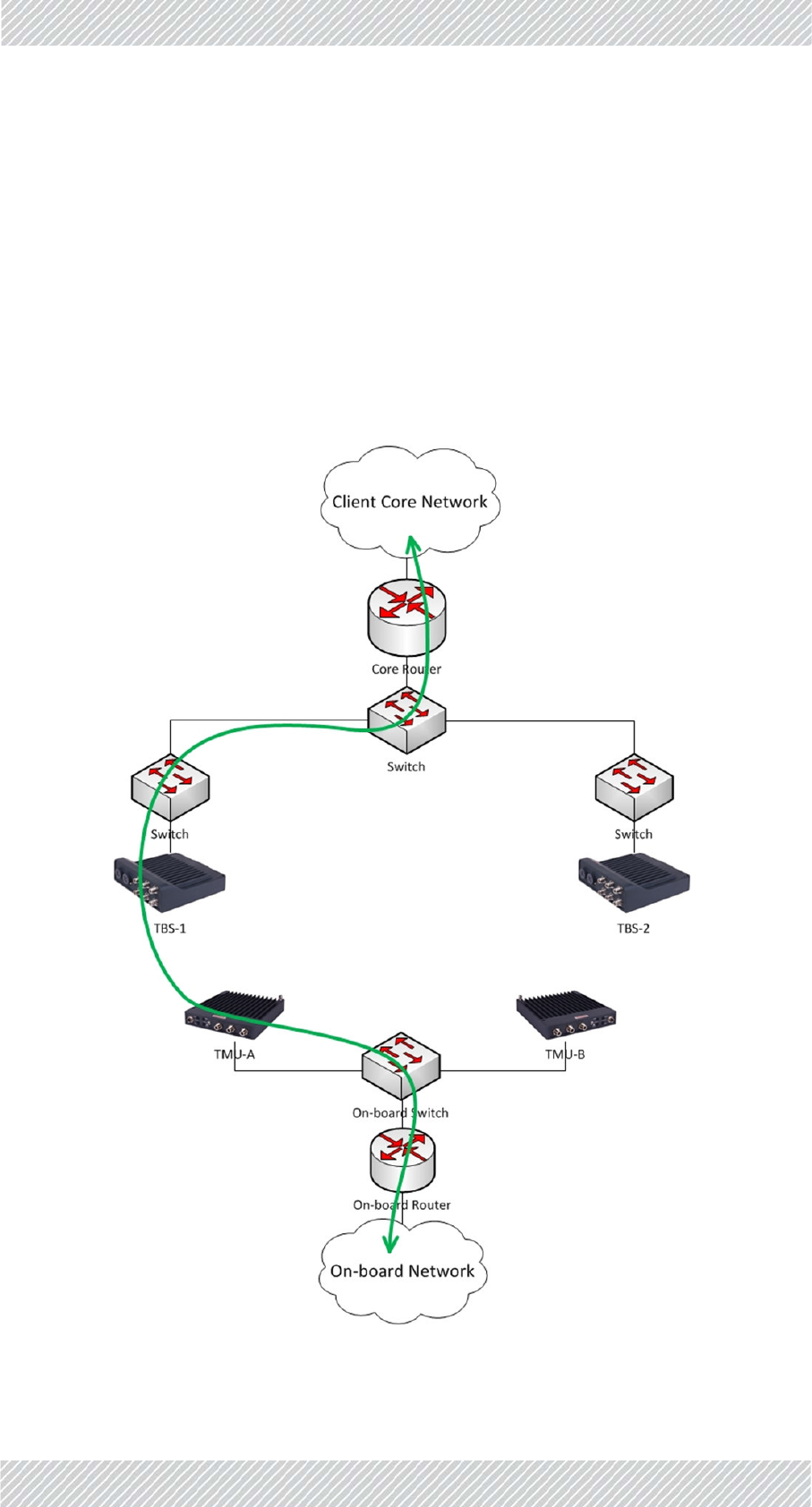
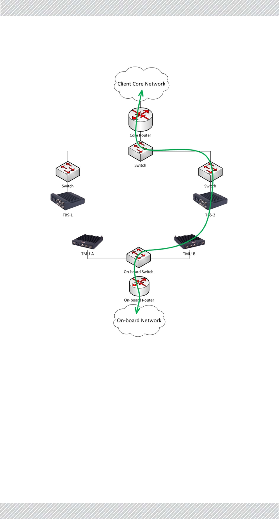
ConsiderFigure 3‐9whereitisshownthatTMU‐AisconnectedtoTBS‐1andisACTIVE
(passingtraffic).Alltrafficflowsinthegreenpath.
TMU‐BisPASSIVE.IthasanidleconnectiontoaTBSanditmonitorsthepotentialthroughput,
butdoesnotpasstraffic.
Figure3‐9:ITHO‐Part1
FinMDeploymentGuide Release4.5.10 3‐14
IntraTrainHandover(ITHO)UpdateMessage NetworkGuidelines
TheIntraTrainHandovermechanismdiscoversthatahigherthroughputcanbeachieved
throughTMU‐B,definedatpresentasPASSIVE.(TMU‐BmaybeconnectedtothesameTBSas
TMU‐Aortoadifferentone‐thisdoesnotaffecttheITHO).
AnITHOisthereforeinitiatedandTMU‐Bisre‐definedasACTIVE.TMU‐Bthensends2update
messages(markedinblueinFigure 3‐10):
•Updatemessagetowaysidecorerouterwithon‐boardrouterMAC‐toupdatetheway‐
sideL2networkofthenewdatapath(sameprocessasintheIBHOupdatedescribed
above)
•UpdatemessagetotheotherTMU(TMU‐A)withthewaysidecorerouterMAC‐to
updatethetrainL2networkofthenewdatapath.
Figure3‐10:ITHO‐Part2
FinMDeploymentGuide Release4.5.10 3‐15
IntraTrainHandover(ITHO)UpdateMessage NetworkGuidelines
Allon‐boardtrafficnowflowsthroughTMU‐BtoTBS‐2inthenewgreenpath:
Figure3‐11:ITHO‐Part3

FinMDeploymentGuide Release4.5.10 4‐1
Chapter4:Configuringthe
RadioNetwork
4.1ScopeofThisChapter
ThischaptershowshowtoworkwiththeConfiguratorApplication,andprovidesafew
examplesofsomeparameters.Italsoincludessometipsandadviceforbestpracticeswhen
workingwiththeConfigurator.
4.2ConnectingtotheUnits
Forafirsttimeconfiguration,allunitsaresettoanIPaddressof10.0.0.120withsubnetmask
255.0.0.0.ThelaptopEthernetcardshouldbesettoafreeIPaddressonthatsubnet(for
example10.0.0.111).
AlloftheTBSsandanyISUsneededmustbephysicallyinstalledbeforeyoucanworkwiththe
Configurator.
4.3AbouttheConfiguratorTool
TheConfiguratorToolisusedtoconfigureeachactivedeviceusedinyourproject:TMUs,
TBSs,andISUs.YoualsousetheConfiguratorTooltosetmanygeneralparametersincluding
IPaddressdetails,gateways,frequenciesandbandwidths,andmuchmore.
ISUsarerequiredonlyinanenvironmentthatdoesnothaveaccesstoaGPSsignal
(tunnels,stations,etc.)
TousetheConfiguratorToolyoumusthaveMSExcel2007orlaterinstalledon
yourlaptop(s).

FinMDeploymentGuide Release4.5.10 4‐2
MethodofOperation ConfiguringtheRadioNetwork
TheConfiguratortoolisanExcelfilethatconsistsoffivetabs:
Main: Providesanoverviewofthecontentsoftheproject,aswellasvariousbuttonsfrom
whichyoucanconfigurespecificdevices.SeeMainTab.
Project:Allowsyoutoentervariousproject‐wideparameters,suchasthefrequenciesand
bandwidthsused,synchronization,units’power,QoS,VLAN,andEthernetmode,
andmore.SeeProjectTab.
Line:AllowsyoutoentertheIPaddressesofthevariousdevicesandgatewaysused,VLAN
definitionsandmore.SeeLineTab.
Towers: AllowsyoutoentertheIPaddressesofthevariousTBSsintheprojectinadditionto
theirneighbors.SeeTowersTab.
Trains:AllowsyoutodefinetherailcarsthatwillbeintheprojectandtheirTMUs.SeeTrain
Tab.
4.3.1MethodofOperation
Briefly,workwiththeConfigurationfileasfollows:
•ChangewhatevervaluesneedtobechangedusingtheConfiguratorfile,
•ClickonRecalcalldata(ifneeded:seepage 4‐5),then
•Savethefile.
•Oncethefileissaved,applythevaluesusingeithertheConfigureUnitbutton(see
page 4‐4),ortheHBSBatchConfigurationbutton(page 4‐4).
TheConfiguratorfilewillconnectwiththeunits,andapplythechanges.
4.4UsingtheConfiguratorTool
ClickonthedesktopicontostarttheConfigurator.Thefilewillopen,andtheMaintabwill
appear.
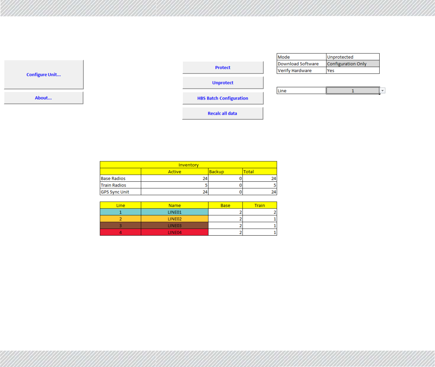
4.4.1MainTab
TheMaintabisshowninFigure 4‐1:
FinMDeploymentGuide Release4.5.10 4‐3
MainTab ConfiguringtheRadioNetwork
Figure4‐1:Configurator‐Maintab
Tableontopright:

FinMDeploymentGuide Release4.5.10 4‐4
MainTab ConfiguringtheRadioNetwork
Setitemsinthistablefirst,beforecarryingoutanyothertasksonthistab.
Figure4‐2:Maintab:Pre‐Conditions
Mode:ShowsthemodeoftheConfiguratorfile(ProtectedorUnprotected)
Downloadsoftware:
(DeterminesworkingdetailsoftheConfigureUnitandHBSBatchConfiguration
buttons)
NomeansthatanychangesyoumakeusingtheConfigureUnitorHBSBatch
ConfigurationbuttonswillaffectthisConfiguratorfileonly,andwillnotbe
downloadedtoanyunits.
ConfigurationOnlymeansthatthechangesyoumakeusingtheConfigureUnit
orHBSBatchConfigurationbuttonswillaffectthisConfiguratorfileandwillbe
downloadedtotherelevantunits.
Configuration&Releasemeansthatthechangesyoumakeusingthe
ConfigureUnitorHBSBatchConfigurationbuttonswillaffectthisConfigurator
file,willbedownloadedtotherelevantunits,butonlyafterthesystemchecks
ifthereisasystemsoftwareupdate.
Compare/Verifyinstructsthesystemtocomparetheconfigurationofthe
relevantunitsasopposedtotheconfigurationasshowninthefileasitisat
present(itrelatestotheopenExcelfile,andnotthefilesavedondisk).
VerifyHardware:Notforcustomeruse.
Line:Indicatesforwhichlineyouaremakingconfigurationchanges.Thisaffectsany
changesyoumakeusingtheConfigureUnitorHBSBatchConfigurationbuttons.
ConfigureUnit:ClicktoopentheConfiguratordialogbox.Thisenablesyoutoconfigure
individualunits,oneatatime.Thelineshownisdeterminedbythevaluein
theLinewindow.SeeConfiguringNetworkUnits.
About... ClicktoopenawindowshowingthesoftwareversionoftheConfigurator
application.
Protect ClicktoprotecttheConfiguratorfilefrombeingchanged.
Unprotect ClicktoallowtheConfiguratorfiletobechanged.Password:psfiberinmotion
HBSBatchConfiguration:
Onceyouhavemadechangesinthisfile,recalculatedanyneededvalues,and
savedthefile,clickthisbuttontoapplythosechangestoalloftheTBSs,

FinMDeploymentGuide Release4.5.10 4‐5
ProjectTab ConfiguringtheRadioNetwork
insteadofjustoneatatime.Acommandlineinterfacewindowwillopen,and
theupdatestatusofeachunitwillbeshown.
Changesforonlyonelinearedone,asdeterminedbythevalueintheLine
window.
Recalcalldata:Afteryouhavemadechangestovariousparametersasdescribedthroughout
thischapter,beforeapplyingthemtoanyunits,clickthistore‐calculateall
otherparametersthatmayhavebeenaffectedbyyourchanges.Thisdoesnot
applyanychangestoanyunits.
LowerTable:Providesanoverviewoftheequipmentandlinesusedinthewholeproject.
4.4.2ProjectTab
TheProjecttabholdsgeneralconfigurationparametersthatapplyacrosstheproject.
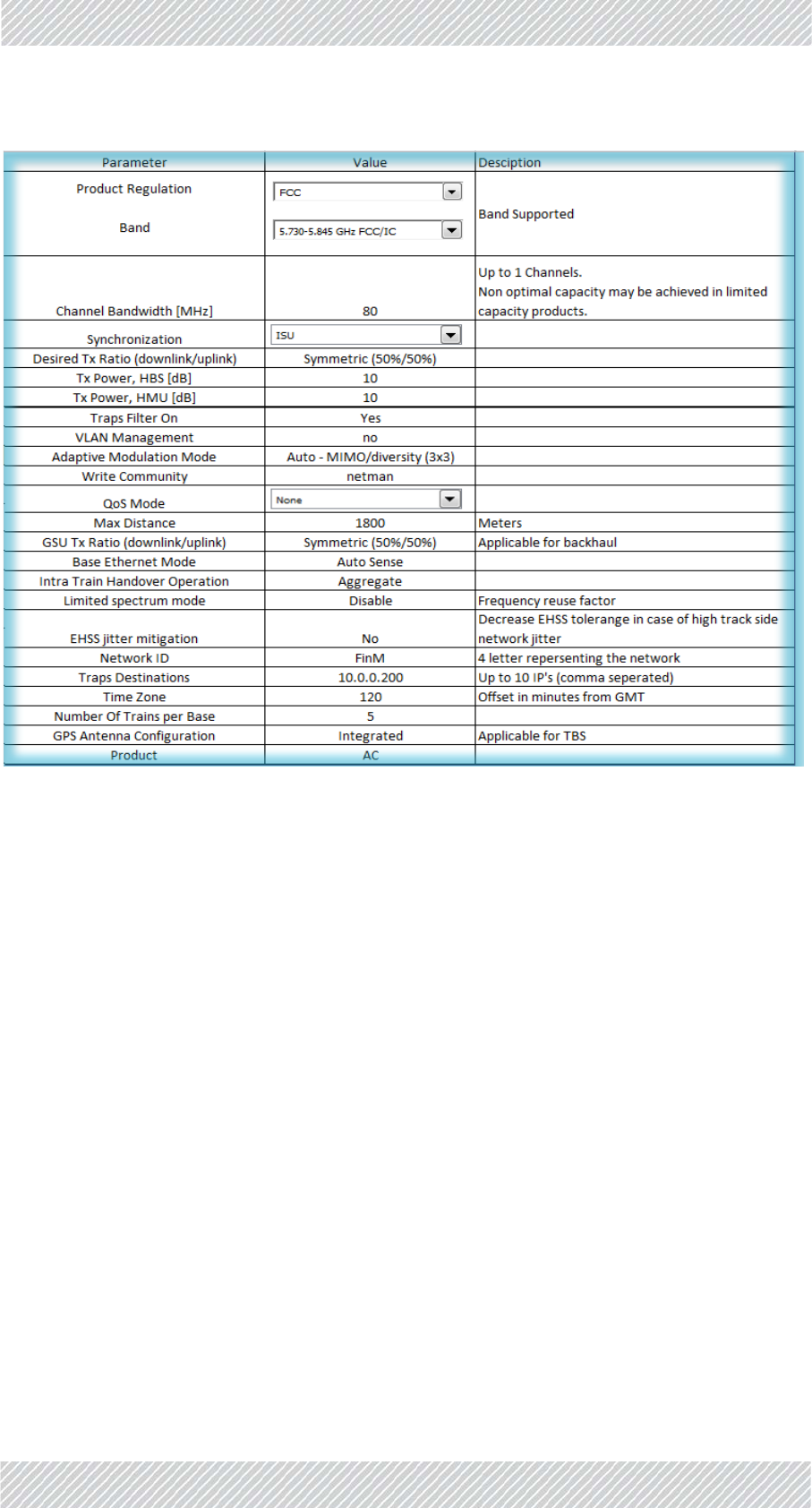
UpperTable
TheuppertableoftheProjecttabisshowninFigure 4‐3:
FinMDeploymentGuide Release4.5.10 4‐6
ProjectTab ConfiguringtheRadioNetwork
Figure4‐3:Configurator‐Projecttab,uppertable
Band:Clickthispull‐downmenutochoosethefrequencybandtobe
usedfortheproject.Onlythosebandsthatareinaccordance
withyourregulatoryenvironmentwillappear.
ChannelBandwidth: Clickthispull‐downmenutochoosethebandwidthtobeused
forthisproject.ThefrequenciesusedintheTowertab(F1,F2,
F3,etc)willbethebasefrequencychoseninBand,withthe
bandwidthadded.
Notethatnotallfrequencybandsallowallbandwidthstobe
used.
Synchronization: Clickthispull‐downmenutochoosethetypeofsynchronization
usedinthisproject:
IntegratedGPS:UseaGPSunitintegratedintheTBS.Usedin
abovegroundscenarios.
GSU:UseanexternalGPSunit.Usedinabovegroundscenarios.
Notethatthisrequiresextrainstallationandconfigurationfor
theGSU.

FinMDeploymentGuide Release4.5.10 4‐7
ProjectTab ConfiguringtheRadioNetwork
ISU:UsetheIndoorSynchronizationUnit.Usedinbelowground
scenarios.
None:Donotusesynchronization
DesiredTxRatio
(downlink/uplink):
Symmetric(50/50):Usethisifthereisnosignificantdifference
inthetransmissionconditionsbetweenTBS‐>TMUandTMU‐
>TBS.
MaxUplink(20/80):Usethisifyourprojectrequirestheuplink
(TMU‐>TBS)tobemuchstrongerthanthedownlink(TBS‐
>TMU).
Uplink(30/70):Usethisifyourprojectrequirestheuplink(TMU‐
>TBS)tobestrongerthanthedownlink(TBS‐>TMU).
Downlink(70/30):Usethisifyourprojectrequiresthedownlink
(TBS‐>TMU)tobestrongerthantheuplink(TMU‐>TBS).
MaxDownlink(80/20):Usethisifyourprojectrequiresthe
downlink(TBS‐>TMU)tobemuchstrongerthantheuplink
(TMU‐>TBS).
TxPower,HBS[dB]: Maximumistypically25dB,minimumis0.Setthevaluethat
willgiveyouthebestthroughputwiththeleastnoise.
TxPower,HMU[dB]: Maximumistypically25dB,minimumis0.Setthevaluethat
willgiveyouthebestthroughputwiththeleastnoise.
TrapsFilterOn: Enablethistofilterthetrapstothosethatarerelevantforyour
project.Ifthisisnotenabled,theneverychangeortrap‐not
matterhowtrivial‐willberecorded,andyourtrapslistwill
quicklybecomeverylargeandcumbersome.
Werecommendtoenablethisparameter.
VLANManagement: EnableifyourprojectisusingaVLAN.
AdaptiveModulation
Mode:
MIMO:(Multi‐In,Multi‐Out)Setthetransmissionmethodtouse
onedatastream,butmultipledatasignals.Thisisusefulinaless
noisyenvironmentthatrequiresahighercapacity,butwhere
dropswillnotlikelyoccur,suchaswhenthetrainisstoppedata
station.
Diversity:Setthetransmissionmethodtousemorethanone
datastream.Thisisusefulwhenthetrainistravellinginanoisy
environmentorwhendropsarelikelytooccur,suchasduring
fastmovement.
AutoMIMO/Diversity:Setthesystemtoautomaticallydetect
theconditionstoswitchbetweenMIMOandDiversity.
WriteCommunity: Setthelinkpasswordhere.

FinMDeploymentGuide Release4.5.10 4‐8
ProjectTab ConfiguringtheRadioNetwork
QoSMode: QualityofService(QoS)isatechniqueforprioritizationof
networktrafficpacketsduringcongestion.RADWINproducts
supporttwoclassificationcriteria,VLANbasedorDiffservbased.
Choosewhichcriteriontouse.Formoredetailsonworkingwith
QoS(seeLowerTable:QualityofService(QoS)Optionson
page 4‐9).
None:DonotenableQoS
VLAN:ChoosetheVLANcriterionforQoS
Diffserv:ChoosetheDiffservcriterionforQoS
MaxDistance: EnterthemaximumdistancebetweentheTBSsandtheTMUs.
MakesuretoentertheunitsincolumnC.
GSUTxRatio(down‐
link/uplink):
SetthisthesameasDesiredTxRatio.Ifitisnotthesame,GPS
synchronizationwillnotworkproperly.
BaseEthernetMode: SettheethernetmodefortheTBSs.Usemanualconfiguration
whenattachedexternalequipmentdoesnotsupportauto‐
negotian.
AutoSense:Detectthelinespeedandduplexmode
automatically,andapplythosevalues.
AutoSense(100M/b):Startat100M/b,butdetecttheline
speedandduplexmodeautomaticall,andchangeitifnecessary
from100M/b.
Force100FullDuplex:Choose100M/bandfullduplexforthe
linespeedandduplexmode.
IntraTrainHandover
Operation:
Setswhichdatastreamdirectionisusedtojudgewhentocarry
outtheintra‐trainhandover.
Uplink:Checktheuplinkdirection(TMU‐>TBS)onlywhen
determiningwhentocarryouttheintra‐trainhandover.
Aggregate:Checkboththeuplinkanddownlinkdirections,and
useanaverageofthesignalstrengthvaluewhendetermining
whentocarryouttheintra‐trainhandover.
Downlink:Checkthedownlinkdirection(TBS‐>TMU)onlywhen
determiningwhentocarryouttheintra‐trainhandover.
Limitedspectrum
mode:
UsedforInterferenceMitigationforCo‐channelNeighbors(see
InterferenceMitigationforCo‐channelNeighborsonpage 4‐17).
Ifyourprojectuses3orfewerfrequencies,thenwerecommend
youusethisoption.
Ifyourprojectusesmorethan3frequencies,thisoptionisnot
needed.

FinMDeploymentGuide Release4.5.10 4‐9
ProjectTab ConfiguringtheRadioNetwork
LowerTable:QualityofService(QoS)Options
ThelowertableoftheProjecttaballowsyoutosetQoSoptions.
ThelowertableoftheProjecttabisshowninFigure 4‐4(VLANcriteriashown):
Figure4‐4:Configurator‐Projecttab,lowertable
QoSOverview
Avarietyoftraffictypescontainingdifferentcontentcantravelthroughoutthenetwork,and
asaresultthroughRADWINequipment.Certaintypesaremoresensitivetodelaysthan
EHSSjittermitigation: EthernetHubSiteSynchronizationjittermitigation:Ifthereisa
highlevelofwaysidenetworkjitter,setthistoYestominimize
theadverseaffectofjitterontransmissionsynchronization.
NetworkID: A4‐lettertermthatrepresentsthenetwork.This“name”isused
inavarietyofplaces.
TrapsDestinations: IPaddressofthetrapdestinationdevice.Forredundancy,you
canhaveupto10differentdestinations.SeparatetheirIP
addresseswithacomma.
TimeZone: Enterthenumberofminutesthatthesystemisaheadof
GreenwichMeanTime(GMTorUTC).
NumberOfTrainsper
Base:
EnterthetotalnumberofTMUsperTBS(thevalueisactually
thenumberofTMUs,nottrains).EachTBSneedsthisvalueto
manageitsresources.TherecanbeuptotwoTMUspertrain,
andupto6TMUsperTBStotal.
GPSAntenna
Configuration:
Integrated:IfyourTBSunitshaveanintegratedGPScapability,
selectthisoption.
External:IfyourTBSunitsdonothaveanintegratedGPS
capability,selectthisoption.Notethatinthiscaseanexternal
GPSUnit(GSU)willberequiredtoimplementGPS
synchronization.
None:IfyouarenotusingGPSsynchronization,selectthis
option.
Product: N:Choosethisoptionifyouareusingthe802.11nradio
transmissionstandard.
AC:Choosethisoptionifyouareusingthe802.11acradio
transmissionstandard.

FinMDeploymentGuide Release4.5.10 4‐10
ProjectTab ConfiguringtheRadioNetwork
others,andassuchtheethernetnetworkplacesatagoneachpacketrepresentingitspriority.
TheRADWINQualityofServicefeature(QoS)canworkwithtwodifferentstandardsoftraffic
prioritization:VLAN(IEEE802.1q/p)andDiffserv(RFC2475).Eachofthesestandardsdivides
theprioritiesdifferently:VLANuses8levels,whileDiffservuses64levels.
RADWINequipmentcanrecognizethesenetworkprioritytags,andcanplacethetrafficin
oneof4differentQoSprioritylevels,asshowninTable 4‐1:
Thatis,ifworkingwiththeDiffservstandard,traffictaggedwithprioritylevelsfrom48to63
aretreatedas“RealTime”,thosewithlevelsfrom47to32aretreatedas“Nearrealtime”,etc.
TheRADWINQualityofServicefeature(QoS)allowsyoutochangewhichstandardpriority
levelistranslatedintoaprioritylevelusedinRADWINequipment.
Example:Ifyouknowyournetworkwillhaveagreatdealofhigherprioritytraffic,butyou
onlywantthehighesttoreceivepreferentialtreatment,youcandefine“RealTime”as
beingfrom55to63,insteadofthedefaultvalues48‐63.Youmustcoveralllevels,soin
thiscase,makesuretore‐define“NearRealTime”as32to54.
Percentages:Youcanseteachprioritylevel(intheuploadanddownloaddirectionseparately)
totakeupacertainpercentageofthetotaltraffic,solongasthatpercentageaddsupto100.
MIR:Youcanalsoplaceanabsolutemaximumlimitontheamountoftrafficallowedtopass
perprioritylevel,nomatterhowmuchtrafficcomesthrough.
SettingupQoS
QoSforTransportationFiberinMotionissetupintwophases:
1. ChoosetheQoSprioritystandard:Projecttab,uppertable,QoSMode
(ChooseNone,VLAN,orDiffserv)
Thelowertablewillshowthedefaultvaluesaccordingtothestandardyouhavechosen.
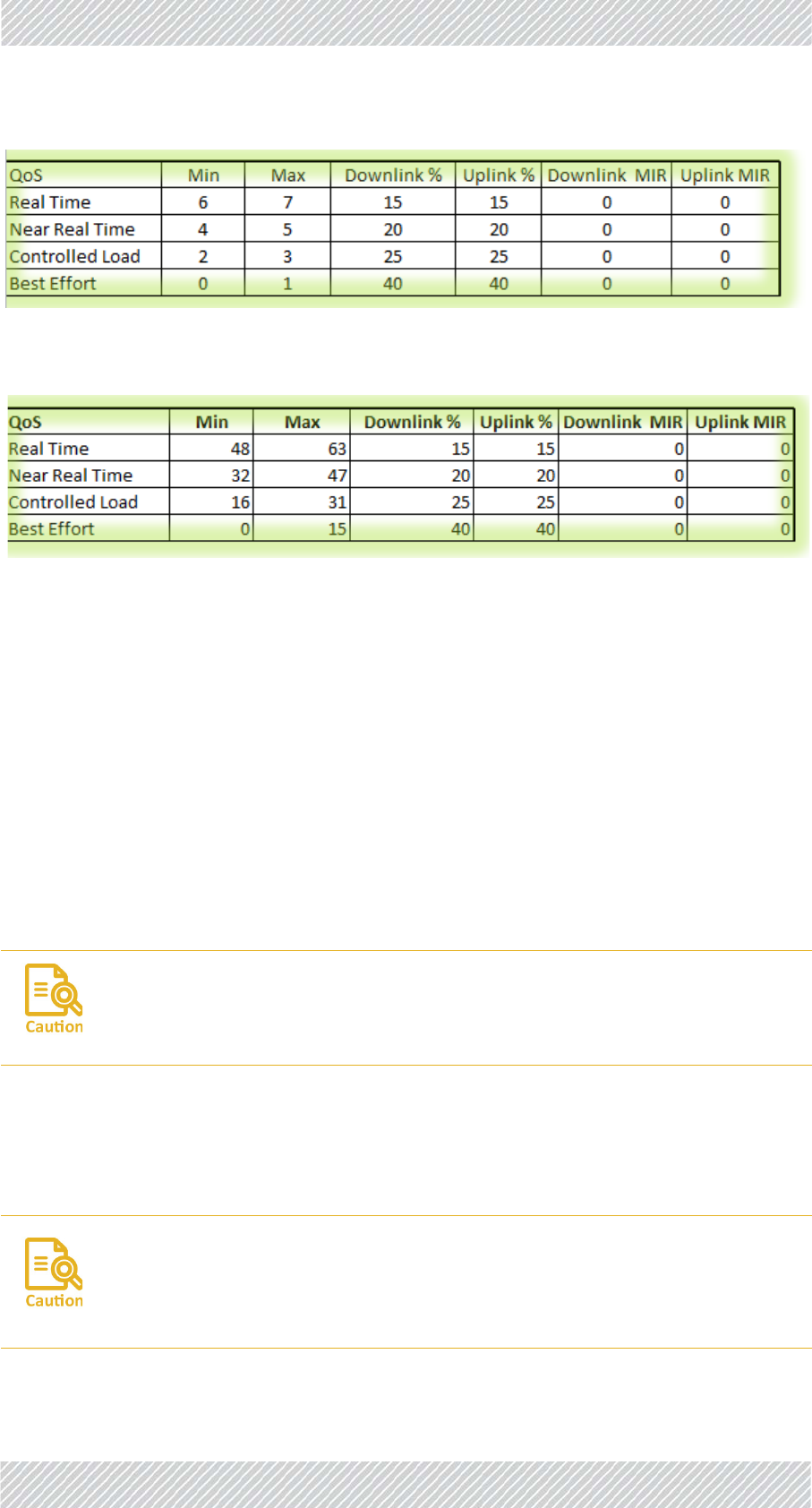
2. Configurethevaluesforeachqualitygroup:Projecttab,lowertable:
Table4‐1:DefaultprioritiesandallocationbyVLANvs.Diffserv
QoSPriorityLevel
StandardPriority
TypicalUse
DiffservVLAN
RealTime 48‐63 6‐7Highpriority:videoconferencing,phone
calls,etc.
NearRealTime 32‐47 4‐5
SlightlylowerprioritythanRealTime,but
withhigh‐qualitydeliverywithguaranteed
minimumlatency.Streamingvideo,internet
sites.
ControlledLoad 16‐31 2‐3
SimilartoBestEffortinuncongested
conditions.Averyhighpercentageof
transmittedpacketswillbedelivered
successfullyandnotexceedtheminimum
delay.Doesnotguaranteeminimumlatency.
BestEffort 0‐15 0‐1Lowestpriority:email,messaging,etc.
FinMDeploymentGuide Release4.5.10 4‐11
ProjectTab ConfiguringtheRadioNetwork
Figure4‐5:Configurator‐Projecttab,lowertable(VLANoptions)
Figure4‐6:Configurator‐Projecttab,lowertable(Diffservoptions)
Min:SettheminimumstandardprioritylevelthattheQoScategorywillreceive:
•InFigure 4‐5(showingvaluesaccordingtotheVLANstandard),RealTimehasa
minimumof6.
•InFigure 4‐6(showingvaluesaccordingtotheDiffservstandard),RealTimehasa
minimumof48.
Max:SetthemaximumstandardprioritylevelthattheQoScategorywillreceive.
•InFigure 4‐5(showingvaluesaccordingtotheVLANstandard),RealTimehasa
maximumof7.
•InFigure 4‐6(showingvaluesaccordingtotheDiffservstandard),RealTimehasa
maximumof63.
3. Downlink%andUplink%:SetthepercentageoftrafficeachQoScategoryistobe
allotted.Thiscanbedifferentforthedownlink(TBS‐>TMU)oruplink(TMU‐>TBS)
direction.IftrafficofacertainQoSlevelismorethanthispercentage,itistreated
asBestEffort.
Youmustmakesuretocoveralltheprioritylevels,otherwisethesystemwill
createerrors.Nowarningwillbegiven.
Thepercentagescannotadduptomorethan100,otherwisethesystemwill
createerrors.Nowarningwillbegiven.
Ifthepercentagesadduptolessthan100,theunusedprioritywillbedistributed
totheremainingpriorities.
FinMDeploymentGuide Release4.5.10 4‐12
LineTab ConfiguringtheRadioNetwork
4. DownlinkMIRandUplinkMIR:Optional.IfyouwanttolimittrafficofacertainQoSleveltoacertainrate,enterthatratehere,in
Mbps(max:100).
4.4.3LineTab
TheLinetabisshowninFigure 4‐7:
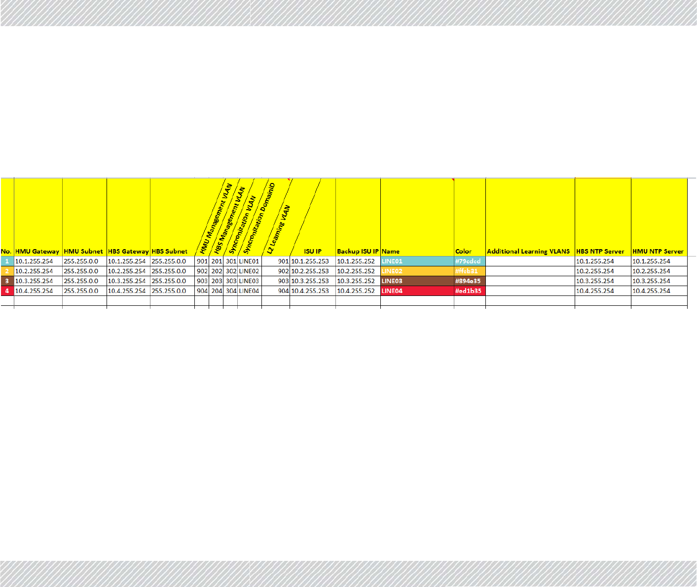
Figure4‐7:Configurator‐Linetab
EnterthevariousIPaddressesforthedevicesshown.
ThedevicesonthefirstlineoftheworksheetareassociatedwithLine1,thoseonthesecondlinewithLine2,etc.
No. Enterthelinenumber.
HMUGateway: TMUgatewayforallTMUsontheline.TheindividualIP
addressesoftheTMUsontherailcarsaredefinedintheTrain
tab(seeTrainTabonpage 4‐17).
HMUSubnet: TMUsubnetforallTMUsontheline.

FinMDeploymentGuide Release4.5.10 4‐13
LineTab ConfiguringtheRadioNetwork
HBSGateway: TBSgatewayforallTBSsontheline.TheindividualIPaddresses
oftheTBSsaredefinedintheTowerstab(seeTowersTabon
page 4‐15).
HBSSubnet: TBSsubnetforallTBSsontheline.
HMUManagement
VLAN:
VLANdefinitionforallTMUs.
HBSManagement
VLAN:
VLANdefinitionforallTBSs.
SynchronizationVLAN: VLANdefinitionforallISUs.
Synchronization
DomainID:
DomainIDforallISUs.
L2LearningVLAN: VLANdefinitionforthedata(traffic)stream.Called“learning”
becauseitrelatestothefactthateachTBSmustlearnaboutthe
newTMUthatiscomingintoitsrange.
ISUIP: IPaddressfortheprimaryISUintheline
BackupISUIP: IIPaddressofthesecondaryISUintheline
Line: Thenameoftheline.Thisnamewillbeusedinseveralplaces,
sousealogicalterm.
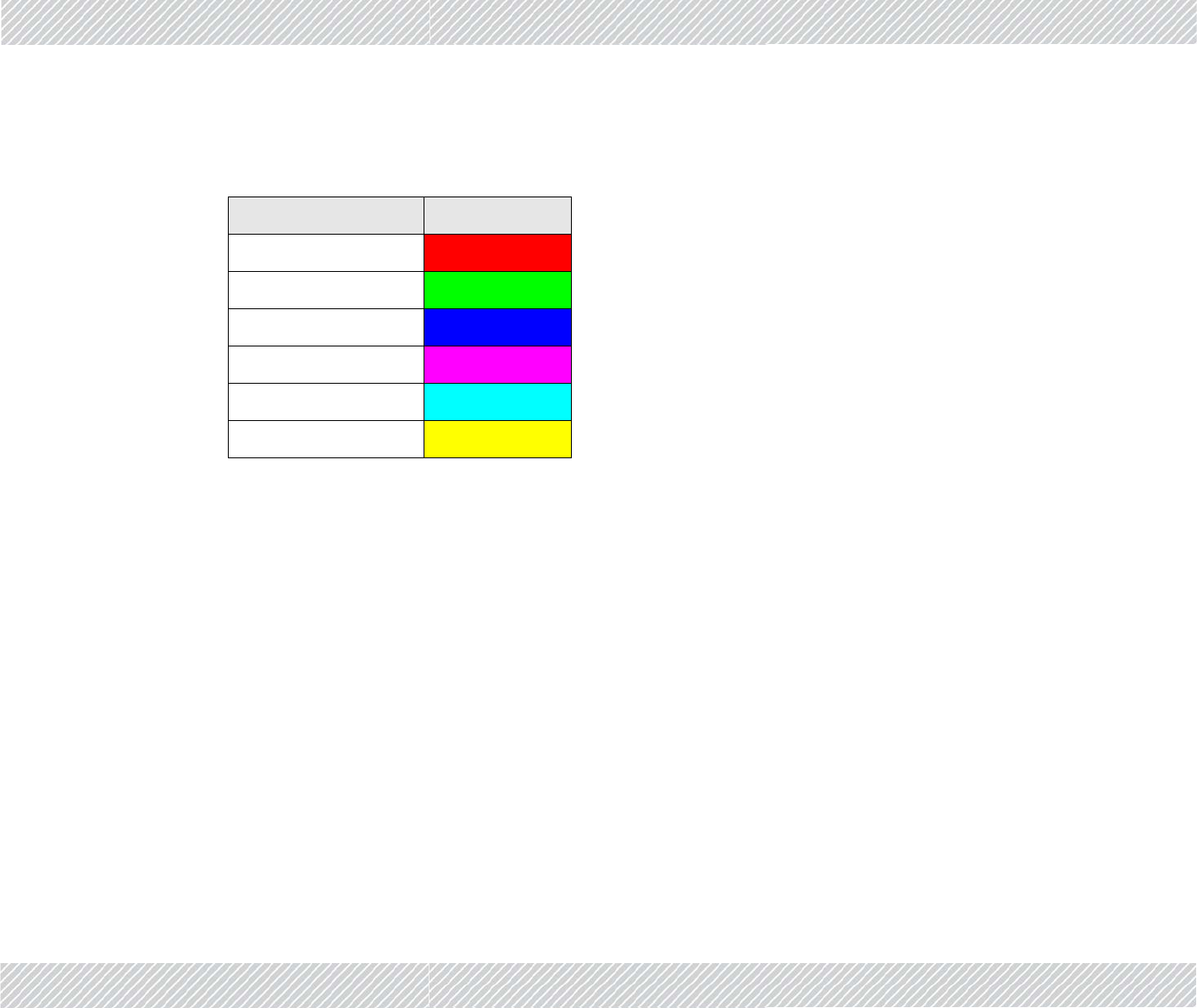
Color: Eachlinehasaseparatecolor,helpingyoutokeepthings
organized.Setthebackgroundcolorforthelinehere.Thecolor
isshown,andisalsousedasabackgroundfortheConfigure
Unitdialogbox(seeConfiguringNetworkUnitsonpage 4‐25),in
theTowerstab(seeTowersTabonpage 4‐15),andtheTraintab
(seeTrainTabonpage 4‐17).
ThefirsttwodigitsarefortheRedcolorcomponent(Hexformat
from00forblacktoFFforRed),thenexttwoarefortheGreen
colorcomponent(Hexformatfrom00forblacktoFFforGreen),
andthelasttwoarefortheBluecolorcomponent(Hexformat
from00forblacktoFFforBlue).
FinMDeploymentGuide Release4.5.10 4‐14
LineTab ConfiguringtheRadioNetwork
AdditionalLearning
VLANs
Notforcustomeruse
HBSNTPServer: IPaddressoftheNetworkTimingProtocolserverforallTBSsin
thenetwork.
HMUNTPServer: IPaddressoftheNetworkTimingProtocolserverforallTMUsin
thenetwork.
Table4‐2:ColorCodes
Value Color
#FF0000 Red
#00FF00 Green
#0000FF Blue
#FF00FF Magenta
#00FFFF Cyan
#FFFF00 Yellow
FinMDeploymentGuide Release4.5.10 4‐15
TowersTab ConfiguringtheRadioNetwork
4.4.4TowersTab
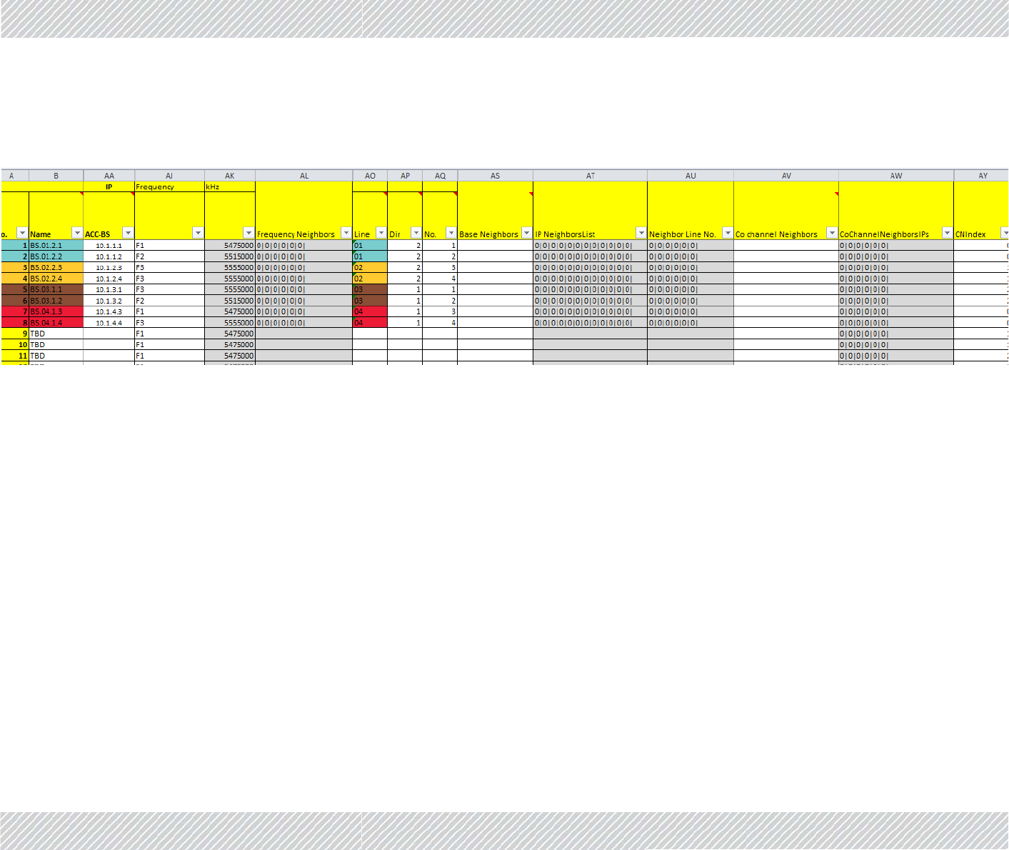
TheTowerstabisshowninFigure 4‐8:
Figure4‐8:Configurator‐Towerstab
UsetheTowerstabtodefinetheconnectivitycharacteristicsofallTBSsintheproject.
InsomeversionsoftheConfigurationfile,someofthefieldsarelinkedtoothers.Thisisproject‐specificandmaynotberelevantforyourproject.
Youmustverifythatallvaluesenteredarethecorrectones.
No. SequencenumberoftheTBSinthewholeproject.
Name EnteranamefortheTBS.Choosealogicalname,asthisnameis
usedinmanyplaces.
ACC‐BS IPaddressoftheTBSunit.

FinMDeploymentGuide Release4.5.10 4‐16
TowersTab ConfiguringtheRadioNetwork
Frequency Fromthepull‐downmenu,choosethefrequencyatwhichthe
TBSunitwillwork.
ThefrequenciesaredeterminedbyBand:andChannel
Bandwidth:valuesintheTowertab.F1,F2,F3,etcwillbethe
basefrequencychoseninBand,withthevaluechosenin
ChannelBandwidthadded.
Forexample,iftheBandchosenis5.475‐5.720GHz,andthe
bandwidthis40MHz,thenF1=5.475GHz,F2=5.515GHz,F3=
5.555GHz,etc.
kHz ThefrequencyinkHzisshownautomaticallyasaresultofyour
choiceintheFrequencycolumn.
FrequencyNeighbors ShowsthefrequenciesoftheneighborsoftheTBS.Thevalues
showndependonthenamesoftheneighborsyouenterinthe
BaseNeighborscolumn.
Line Choosethenumberofthelinehere,precededbyazero.
Dir Write1ifthereisoneTBSthatservesbothdirections,write2of
thereisaTBSforeachdirection.
No.SequencenumberoftheTBSinthespecificline.
BaseNeighbors Enterthename(s)ofeachTBSthatiscloseenoughtobe
consideredaneighbor.Becarefultoentertheexactsameterm
fortheneighboringTBSasshownintheNamecolumnforthat
unit.Separatemultiplevaluesbyacomma.
IPNeighborsList ShowstheIPaddressesoftheneighboringTBSunitsin
accordancewiththelistyoucreatedintheBaseNeighbors
column.
NeighborLineNo. Shows,inorder,thelinenumberforeachneighboringTBSunit,
naccordancewiththelistyoucreatedintheBaseNeighbors
column.
Co‐ChannelNeighbor UsedforInterferenceMitigationforCo‐channelNeighbors.(see
InterferenceMitigationforCo‐channelNeighborsonpage 4‐17).
Ifyourprojectuses3orfewerfrequencies,thenwerecommend
youusethisoption.
Enterthename(s)oftheco‐channelneighbor(s).Ifthereare
morethanone,separatethembyacomma(nospaces!).
Co‐ChannelNeighbor‐
sIPs
ShowstheIPaddress(es)oftheco‐channelneighbor(s)in
accordancewiththenamesyourecordedintheCo‐Channel
Neighborcolumn.UsedforInterferenceMitigationforCo‐
channelNeighbors.
CNIndex IndicateswhichTBSwillusewhichtimeslotsintheframe,inthe
InterferenceMitigationforCo‐ChannelNeighborsoption.

FinMDeploymentGuide Release4.5.10 4‐17
TrainTab ConfiguringtheRadioNetwork
4.4.5TrainTab
TheTraintabisshowninFigure 4‐9:
Figure4‐9:Configurator‐Traintab
4.5InterferenceMitigationforCo‐channel
Neighbors
Ifyoursystemuses3orfewerfrequencies,werecommendthatyouusetheCo‐Channel
NeighborInterferenceMitigationmethoddescribedheretoreduceinterferencebetween
TBSs.
•ThismethodisusedinadditiontotheHubSiteSynchronizationmethod.
No. SequencenumberoftheTMUinthewholeproject.
IP IPaddressoftheTMU.
Line LineonwhichtheTMUworks.
Num WhentwoTMUsareusedonacar,setherewhichTMUis“1”
andwhichoneis“2”.Thisisnotnecessarilythe“active”or
“passive”TMU;thatisdeterminedbyconditionsinthefieldand
canchangefromminutetominute.
Car#1 NameofCar#1.Choosealogicalname,asthisnameisusedin
manyplaces.
(Car#2) (Optional)NameofCar#2.Choosealogicalname,asthisname
isusedinmanyplaces.
Car#1RouterIP IPaddressofrouterinCar#1.
NotethatthisistheIPaddressoftherouter,andnotofthe
TMU,oranyotherindividualpieceofequipmentonboard.This
keepsthenetworksimple‐astheTBS,ISUs,andotheritems
relatetothissingleIPaddress,andnottothemanyIPaddresses
oftheindividualitemsofequipment.
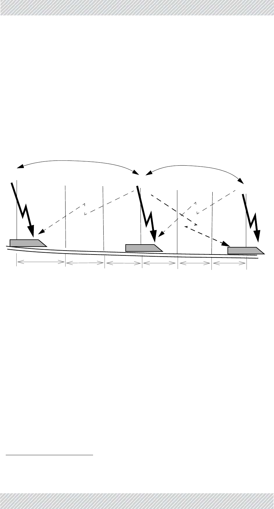
FinMDeploymentGuide Release4.5.10 4‐18
BasicSituation ConfiguringtheRadioNetwork
•Ifyoursystemusesmorethan3frequencies,thismethodofinterferencemitigationis
notneeded.
4.5.1BasicSituation
ThethreefrequenciesareusedontheTBSsinastaggeredfashion:TBS1usesF1,TBS2uses
F2,TBS3usesF3.Thepatternisthenrepeated:TBS4hasagainF1,TBS5hasF2,TBS6hasF3,
andsoon.
WeassumethatthenominaldistancebetweeneachTBSisatleast500m(belowground;
abovegroundthisvaluecanbeaslargeas2000m).SeeFigure 4‐10.
Figure4‐10:Co‐ChannelNeighbors
Atagivenmoment,arailcar(withTMU1)issynchronizedwithTBS1,andusingfrequencyF1.
Atthissamemoment,thisrailcarisabout1500metersawayfromTBS4,whichisalsousing
F11.
AnysignalthatTMU1receivesfromTBS4atthispointisconsideredinterference.Ifthesignal
fromTBS4isstrongenough,theinterferencecanharmthethroughput,andneedstobe
mitigated.
Thissituationcontinuesthroughouttheline‐TBS7caninterferewithTBS4/TMU4,andinturn
TBS4caninterferewithTBS7
/TMU7.TBS7canfurtherinterferewithTBS10,TBS10can
interferewithTBS7andTBS13,andsoondowntheline.
Thetwounitsthatcaninterferewitheachotherarecalled“co‐channelneighbors”.
4.5.2NecessaryPre‐Conditions
Ifthe“Co‐ChannelNeighborInterferenceMitigation”optionisconfigured,itwillbeactivated
orde‐activatedautomaticallyaccordingtotheconditionsdescribedbelow.Notethatthe
activationconditionsandde‐activationconditionsarenotexactlysymmetrical.
1. Iffewerthan3frequenciesareused,thevalueswouldbe1000mfortwoand500mforonefrequency.
TBS1 TBS4 TBS7
TBS2 TBS3 TBS5 TBS6
TMU1 TMU4 TMU7
500m 500m 500m 500m 500m 500m
co‐channelneighbors co‐channelneighbors

FinMDeploymentGuide Release4.5.10 4‐19
NecessaryPre‐Conditions ConfiguringtheRadioNetwork
ActivationConditions
»TheTBSco‐channelneighboristransmittingwiththePrimaryTMUonitsrailcar1,
AND
»ThedetectedsignalfromtheTBSco‐channelneighborisabovethethresholdsignal
strengthforactivation(seeTable 4‐3).
De‐ActivationConditions
»TheTMUoftheTBSco‐channelneighborisre‐definedastheSecondaryTMU,
OR
»ThedetectedsignalfromtheTBSco‐channelneighborisbelowthethresholdsignal
strengthforde‐activation(thevaluesaredifferentfromthatofactivation:seeTable 4‐
4).
1. Thisisthe“active”TMU.Iftheco‐channelneighboristransmittingwithitsSecondaryTMU,thesignalwillbe
weakerandsporadic,resultinginalowenoughinterferencelevelastobeinsignificant.
Table4‐3:Thresholdsignalstrengthlevels‐activationcriteria
SignalStrengthbetween
TBSandTMU
Differenceinsignal
strengthbetweenTBS
anditsco‐channel
neighbor
ActivateOption?
‐70orabove Greaterthan16 No
‐70orabove 16orless Yes
‐74to‐71 Greaterthan14 No
‐74to‐71 14orless Yes
‐78to‐75 Greaterthan12 No
‐78to‐75 12orless Yes
‐79orbelow Greaterthan9No
‐79orbelow 9orless Yes
Table4‐4:Thresholdsignalstrengthlevels‐de‐activationcriteria
SignalStrengthbetween
TBSandTMU
Differenceinsignal
strengthbetweenTBS
anditsco‐channel
neighbor
De‐Activate
Option?
‐70orabove Greaterthan20 Yes
‐70orabove 20orless No
‐74to‐71 Greaterthan18 Yes

FinMDeploymentGuide Release4.5.10 4‐20
MethodofOperation ConfiguringtheRadioNetwork
4.5.3MethodofOperation
Theco‐channelneighborinterferencemitigationoptionworksasfollows:
Splittimeslots:TBS1isconfiguredtosplitthetimeslotsintheframebetweenitandbetween
its“co‐channelneighbor”(inourcase,withthreefrequencies,it’swithTBS4)1.The
resultforthefirstco‐channelneighborpairisthatTBS1transmitsonhalfofthetime
slots,andTBS4transmitsontheotherhalf.SeeFigure 4‐11.
TMU1isinstructedtoreceivethosetimeslotsthatwereassignedtoTBS1,andignore
others.
Noticethatinourexample,TBS1andTBS7areassignedthesametimeslots.Thisis
notaproblembecauseTBS1andTBS7aresofarawayfromeachotherthattheir
mutualsignalsdonotinterfere.
Repeatforallco‐channelneighbors:ThisconfigurationisepeatedwithTBS2vs.TBS5,again
withTBS3vs.TBS6,andevenwithTBS7vs.TBS4,andsoondowntheline.
‐74to‐71 18orless No
‐78to‐75 Greaterthan16 Yes
‐78to‐75 16orless No
‐79orbelow Greaterthan13 Yes
‐79orbelow 13orless No
1. WhichTBSreceiveswhichtimeslotsisdeterminedbytheCNIndexparameter(seepage 4‐24)
Table4‐4:Thresholdsignalstrengthlevels‐de‐activationcriteria
SignalStrengthbetween
TBSandTMU
Differenceinsignal
strengthbetweenTBS
anditsco‐channel
neighbor
De‐Activate
Option?
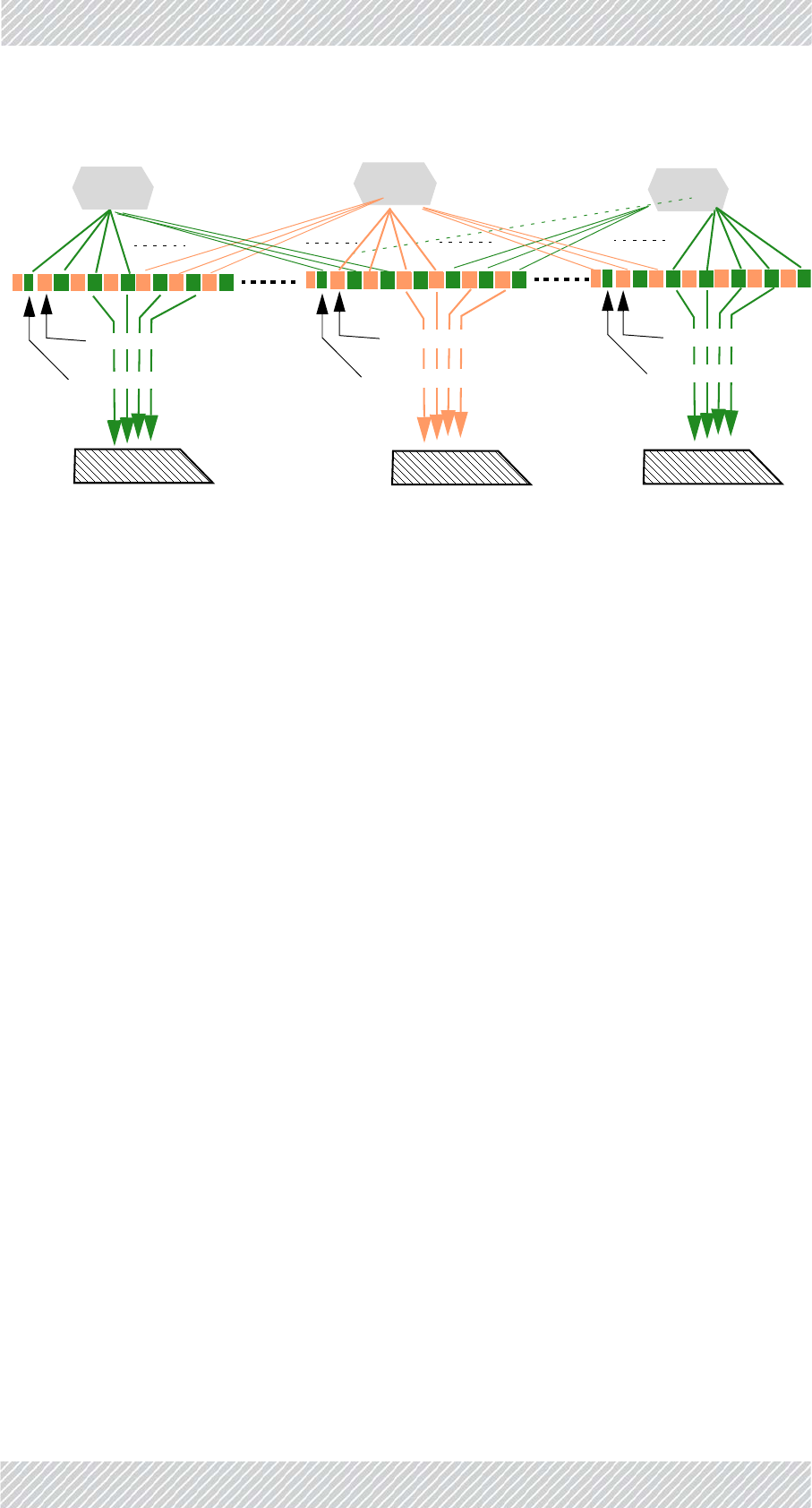
FinMDeploymentGuide Release4.5.10 4‐21
ConfiguringtheCo‐ChannelNeighborInterferenceMitigationOption ConfiguringtheRadioNetwork
Figure4‐11:Dividingtimeslotsbetweenco‐channelneighbors
Thissplittingoftimeslotsisenabledonlyiftheactivationconditionsdescribedabove(see
ActivationConditions)aremet.
Thingscanchangerapidly,soatthemomentthede‐activationconditionsaremet(seeDe‐
ActivationConditions),thedivisionoftimeslotsisnolongercarriedout.
Whentheconditionsreturntotheactivationconditions,thedivisionoftimeslotsisrenewed.
4.5.4ConfiguringtheCo‐ChannelNeighborInterference
MitigationOption
ConfigureeachTBSfor“Co‐ChannelNeighborInterferenceMitigation”asfollows:
5. OpentheConfigurator.
6. SelecttheMaintab
7. ClickUnprotect.
8. EnterthepasswordandclickOK.
9. SelecttheProjecttab(seeFigure 4‐12):
TBS1 TBS4 TBS7
TMU1 TMU4 TMU7
ReceivesTBS1timeslotsonly
TimeslotassignedtoTBS4
TimeslotassignedtoTBS1
ReceivesTBS4timeslotsonly
TimeslotassignedtoTBS4
TimeslotassignedtoTBS1andTBS7
ReceivesTBS7timeslotsonly
TimeslotassignedtoTBS4
TimeslotassignedtoTBS7
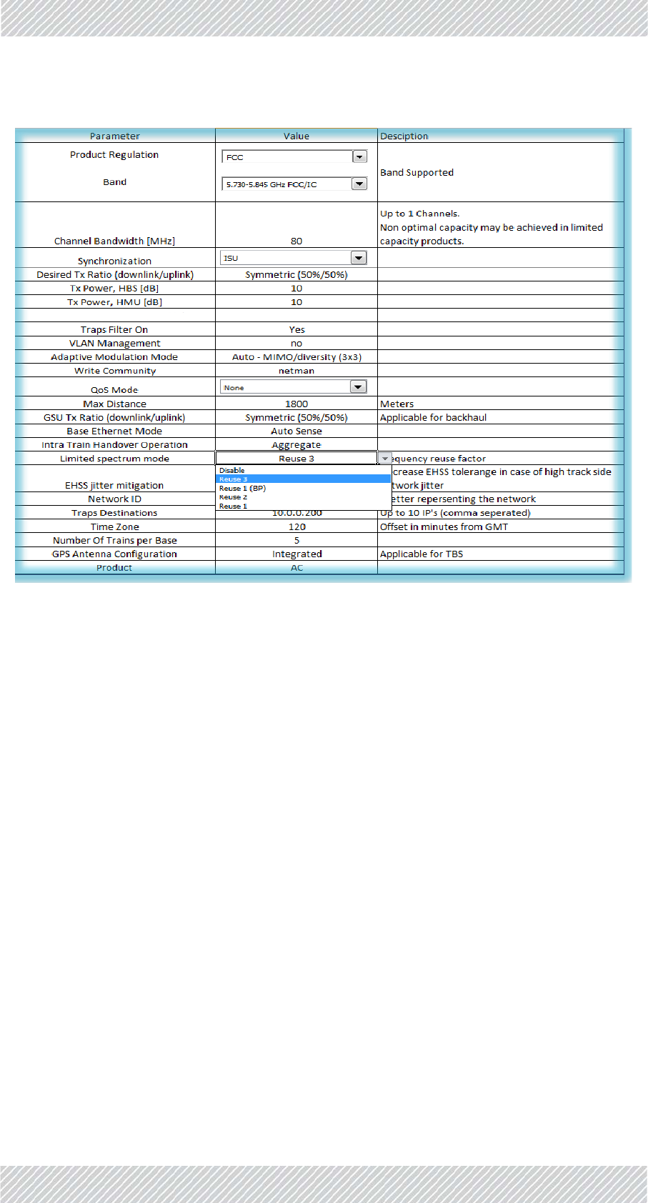
FinMDeploymentGuide Release4.5.10 4‐22
ConfiguringtheCo‐ChannelNeighborInterferenceMitigationOption ConfiguringtheRadioNetwork
Figure4‐12:ProjectTab:LimitedSpectrumMode
10.SelecttheLimitedSpectrumModeoption
11.ChooseReuse3fromthepull‐downmenu.Thiswillinstructthesystemthatyou
areusing3frequencies.Ifyouareusing2frequencies,chooseReuse2,ifyouare
using1frequency,chooseReuse1.

FinMDeploymentGuide Release4.5.10 4‐23
ConfiguringtheCo‐ChannelNeighborInterferenceMitigationOption ConfiguringtheRadioNetwork
12.ClicktheTowerstab:
Figure4‐13:TowersTaboftheConfigurator
•ColumnAshowsthenumberofeachTBS.
•ColumnBshowsthe“name”(orserialnumber)ofeachTBS.
•ColumnAAshowstheIPaddressofeachTBS.
•ColumnAJindicateswhichfrequency(F1,F2,orF3inourexample)isbeingused
forthespecificTBS.
•ColumnAKshowsthevalueofthefrequencyinkHz.
•ColumnAVshowsthename(s)oftheco‐channelneighbor(s).
•ColumnAWshowstheIPaddress(es)oftheco‐channelneighbor(s).
•ColumnAYshowsthe“CNIndex”(whichtimeslottheindicatedTBSistouse).
Wecanseethatinourexample,wearere‐usingF1throughF3
(columnsoftheExcelsheetnotneededhavebeencollapsedforclarity).
13.Recordtheco‐channelneighbor(s)ofeachTBSasfollows:
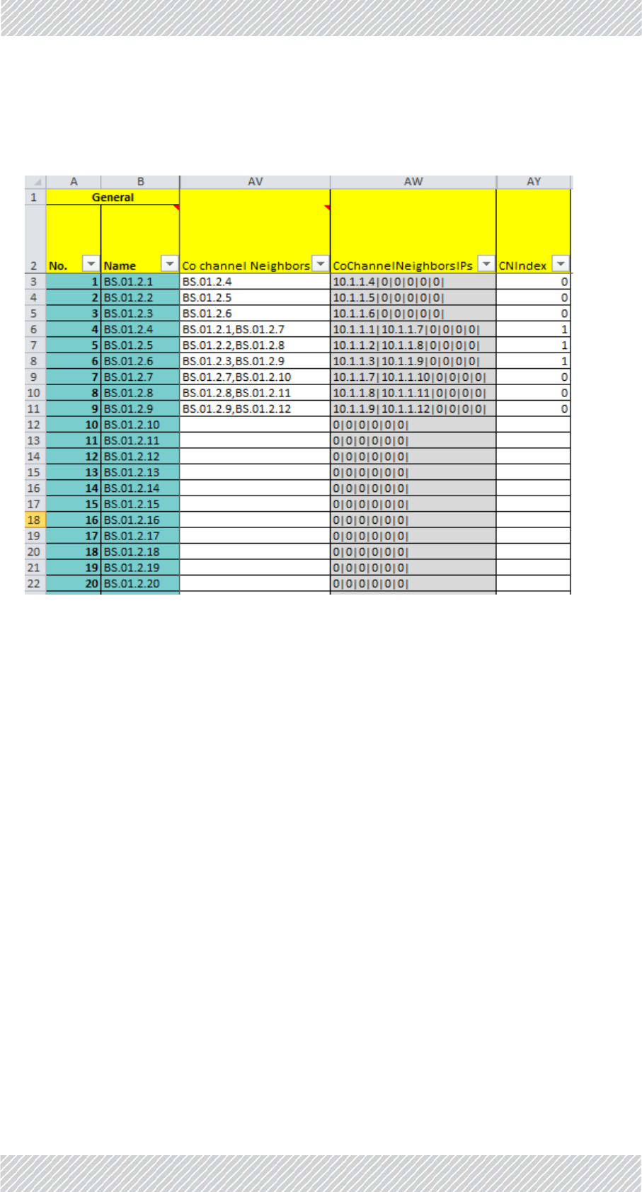
FinMDeploymentGuide Release4.5.10 4‐24
ConfiguringtheCo‐ChannelNeighborInterferenceMitigationOption ConfiguringtheRadioNetwork
IncolumnAV(Co‐channelNeighbors),recordthenameoftheco‐channelneighborTBS(s).
Iftherearetwoco‐channelneighbors,recordeachneighbor’snameseparatedbya
comma(nospaces!),asshowninFigure 4‐14:
Figure4‐14:RecordingCo‐ChannelNeighbors
TheIPaddress(es)oftheco‐channelneighbor(s)appearautomaticallyincolumnAW.
Inourexample,theco‐channelneighborofTBS1(BS.01.2.1)isBS.01.2.4,thatofTBS2
(BS.01.2.2)isBS.01.2.5,andofTBS3(BS.01.2.3)isBS.01.2.6.
StartingfromTBS4,eachTBShastwoco‐channelneighbors:theneighborsofTBS4
(BS.01.2.4)areTBS1(BS.01.2.1)andTBS7(BS.01.2.7),andsoon.
Thispatternwillrepeatitselfuntiltheendoftheline.ThelastthreeTBSsattheendofthe
line,likethefirstthree,willhaveonlyoneco‐channelneighbor.
14.Completerecordingalloftheco‐channelneighborsforallTBSsinthespecificline
(wehaveonlyrecordeduptoTBS9inourexample).
15.IncolumnAY,recordtheCNIndex:ThisindicateswhichTBSwillusewhich
timeslotsintheframe‐thefirstpartorthesecondpart(seealsoFigure 4‐11).
Record0fortheTBSsthatwillusethefirstpart,and1fortheTBSthatwillusethe
secondpart.
Inourexample,TBS1,2,and3usethefirstpartofthetimeslotsintheframe(0is
recorded),whileTBS4,5,and6usethesecondpartofthetimeslots.ForTBS7,8,and9,
theyagainusethefirstpartofthetimeslots(so,forinstanceTBS4alwaysusesadifferent
partoftheframethanitsco‐channelneighbor:CNIndex1vs.CNIndex0forTBS1andfor
TBS7).Thepatternrepeatsitselfuntiltheendoftheline.

FinMDeploymentGuide Release4.5.10 4‐25
ConfiguringNetworkUnits ConfiguringtheRadioNetwork
16.Onceyouhaveenteredallthenecessaryinformation,selecttheMaintab.
17.ClickRecalcalldatatoupdatethesystemwiththechangesyouhavemade,and
savethefile.
4.6ConfiguringNetworkUnits
ConfiguringanIndividualUnit:
Toconfigureindividualnetworkunitsoneatatime(TBS,TMU,andISUscanbeconfig‐
ured),clickConfigureUnitontheMaintaboftheConfigurator.ThisopenstheConfigura‐
tordialogbox.Seesectionssee4.6.1onpage 4‐25throughsee4.6.3onpagepage 4‐29
fordetailsonworkingwiththeConfiguratordialogbox.
ConfiguringManyUnitsatOnce:
YoucanconfigurealltheTBSunitsintheline,asdeterminedbythevalueintheLinewin‐
dow.DothisbyclickingtheHBSBatchConfigurationbutton.Thiswilltakeallofthe
parametervaluesthatareinthisfileforthespecificline,andapplythemtoalloftheTBS
unitsdefinedintheline.ConnectioniscarriedoutaccordingtotheIPaddressesasappear
inthisfile.
4.6.1ConfiguringTransportationBaseStations(TBSs)
UsethisproceduretocarryoutchangesintheconfigurationparametersoftheTBSs.This
includeschangingorsettingitsIPaddress.
1.Forafirst‐timeconfiguration,connecttheTBS’sPoEsockettoaPoEdevice(seeSite
Installationforconnectioninstructions),andinturn,connectthePoEdevicetoyour
laptoporaLANconnection.
Forare‐configurationofaTBSalreadyinstalledinthefield,youcanrelyonyournet‐
work’sconnection.
2. RuntheConfigurator.
3. FromtheMaintab,clicktheLinepull‐downmenuandselectthelineonwhichthe
TBSisdefined(seeFigure 4‐2).
4. FromtheDownloadSoftwarepull‐downmenu,selecttheappropriate
configurationoption(seepage 4‐4foradescriptionoftheseoptions).
5. ClickConfigureUnit.Thefollowingwindowwillappear:
Configureallnetworkunitsbeforeyouinstalltheminthefield.

FinMDeploymentGuide Release4.5.10 4‐26
ConfiguringTransportationBaseStations(TBSs) ConfiguringtheRadioNetwork
Figure4‐15:TBS‐FirsttimeInstallation
6. Type:Selecttheradiotype‐AccessRadio,asshowninFigure 4‐15.
7. BaseName:Selectthenameoftheunit.Thisnameisassociatedwithvarious
parametervaluesintheConfiguratorfile.Theseparameterswillbedownloadedto
theunitwhoseIPaddressappearsintheFirstInstallationwindow.Alistofthese
namesaretakenfromthosedefinedintheTowerstab,andcomefromtheselected
lineonly.
8. Role:LeavethissettingasPrimary.
9. FirstInstallation:Forafirst‐timeinstallation,leavethisoptionselectedsothe
defaultIPaddresswillappear.Theparameterswillbedownloadedtotheunitwith
thisIPaddress.
10. ClickOKtocompletetheconfiguration.TheConfiguratorwilltaketheparameters
associatedwiththeselectedBaseNameaswellasotherparametersassociated
withitsline,anddownloadthemtotheunitwhoseIPaddressisshownintheFirst
Installationwindow.
Itmaytakeaboutaminutetocomplete.Youwillreceiveoneofthecompletionmes‐
sagesdescribedinConfiguratorMessagesbelow.
Tore‐configureaunitthatisalreadyinstalled:
1.RepeatStepssee1.throughsee8.above,relyingonyournetwork’sconnectionto
theunit.
2. RemovethecheckmarkfromFirstInstallation,andentertheIPaddressoftheunit
youwishtore‐configure:
Thebackgroundcolorofthedeviceconfigurationwindowisthesamecoloras
thatdefinedinLinetab,Namecolumn.
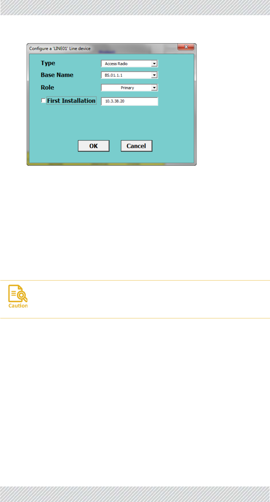
FinMDeploymentGuide Release4.5.10 4‐27
ConfiguringTransportationMobileUnits(TMUs) ConfiguringtheRadioNetwork
Figure4‐16:TBS‐Re‐configuration
3. ClickOK.TheConfiguratorwilltaketheparametersassociatedwiththisnameas
wellasotherparametersassociatedwithitsline,anddownloadthemtotheunit
whoseIPaddressappearsintheFirstInstallationwindow.
Itmaytakeaboutaminutetocomplete.Youwillreceiveoneofthecompletionmes‐
sagesdescribedinConfiguratorMessagesbelow.
4.6.2ConfiguringTransportationMobileUnits(TMUs)
UsethisproceduretocarryoutchangesintheconfigurationparametersoftheTMUs.This
includeschangingorsettingitsIPaddress.
1.Forafirst‐timeconfiguration,connecttheTMU’sPoEsockettoaPoEdevice(see
SiteInstallationforconnectioninstructions),andinturn,connectthePoEdeviceto
yourlaptoporaLANconnection.
Forare‐configurationofaTMUalreadyinstalledinthefield,youcanrelyonyour
network’sconnection.
2. RuntheConfigurator.
3. FromtheMaintab,clicktheLinepull‐downmenuandselectthelineonwhichthe
TMUisdefined(seeFigure 4‐2).
4. FromtheDownloadSoftwarepull‐downmenu,selecttheappropriate
configurationoption(seepage 4‐4foradescriptionoftheseoptions).
5. ClickConfigureUnit.Thefollowingwindowwillappear:
SinceTMUsareusuallymobile,makesurethesedeviceswillbeincontinuous
contactduringtheconfigurationprocess.Ourrecommended“bestpractice”isto
findanopportunitywhentheTMUtobeconfiguredisimmobile.

FinMDeploymentGuide Release4.5.10 4‐28
ConfiguringTransportationMobileUnits(TMUs) ConfiguringtheRadioNetwork
Figure4‐17:TMU‐FirsttimeInstallation
6. Type:Selecttheradiotype‐TrainRadio,asshowninFigure 4‐17.
7. Car:Selectthenameofthetraincaronwhichtheunitistobeinstalled.Alistof
thesenamesaretakenfromthosedefinedintheTrainstab,Carcolumn,andcome
fromtheselectedlineonly.
8. CarRouter:ThisshowstheIPaddressoftherouterontheselectedtraincar.thisIP
addressisdefinedintheTrainstab,CarRouterIPcolumn.
9. FirstInstallation:Forafirst‐timeinstallation,leavethisoptionselectedsothe
defaultIPaddresswillappear.Theparameterswillbedownloadedtotheunitwith
thisIPaddress.
10. ClickOKtocompletetheconfiguration.TheConfiguratorwilltaketheparameters
associatedwiththeselectedCarname,aswellasotherparametersassociatedwith
itsline,anddownloadthemtotheunitwhoseIPaddressisshownintheFirst
Installationwindow.
Itmaytakeaboutaminutetocomplete.Youwillreceiveoneofthecompletionmes‐
sagesdescribedinConfiguratorMessagesbelow.
Tore‐configureaunitthatisalreadyinstalledinthefield:
1.RepeatStepssee1.throughsee8.above,relyingonyournetwork’sconnectionto
theunit.
2. RemovethecheckmarkfromFirstInstallation,andentertheIPaddressoftheunit
youwishtore‐configure.NotethatthecorrectIPaddressoftheCarRouterwill
appear.

FinMDeploymentGuide Release4.5.10 4‐29
ConfiguringIndoorSynchronizationUnits(ISUs) ConfiguringtheRadioNetwork
Figure4‐18:TMU‐Re‐configuration
3. ClickOK.TheConfiguratorwilltaketheparametersassociatedwiththeunitofthis
name,anddownloadthemtotheunitwhoseIPaddressappearsintheFirst
Installationwindow.
Itmaytakeaboutaminutetocomplete.Youwillreceiveoneofthecompletionmes‐
sagesdescribedinConfiguratorMessagesbelow.
4.6.3ConfiguringIndoorSynchronizationUnits(ISUs)
UsethisproceduretocarryoutchangesintheconfigurationparametersoftheISUs.This
includeschangingorsettingitsIPaddress.
1.Forafirst‐timeconfiguration,connecttheISU’ssyncsockettoyourlaptoportoa
LANconnection.ConnectACpowertoitspowerinput.SeeSiteInstallationforcon‐
nectioninstructions.
Forare‐configurationofanISUalreadyinstalledinthefield,youcanrelyonyour
network’sconnection.
2. RuntheConfigurator.
3. FromtheMaintab,clicktheLinepull‐downmenuandselectthelineonwhichthe
ISUisdefined(seeFigure 4‐2).
4. FromtheDownloadSoftwarepull‐downmenu,selecttheappropriate
configurationoption(seepage 4‐4foradescriptionoftheseoptions).
5. ClickConfigureUnit.Thefollowingwindowwillappear:

FinMDeploymentGuide Release4.5.10 4‐30
ConfiguringIndoorSynchronizationUnits(ISUs) ConfiguringtheRadioNetwork
Figure4‐19:ISU‐Firsttimeinstallation
6. Type:Selecttheunittype‐LinesyncUnit(ISU),asshowninFigure 4‐19.
7. UnitName:Thenameoftheunitwhichhastheassociatedparametervalues.This
nameconsistsofISU.LineNumber.Alistofthesenamesaretakenfromthose
definedintheLinetab.
8. Role:SelecttheroleoftheISU.ThisiseitherPrimaryorSecondary.SeetheLine
tab:ISUIP,andBackupISUIPfordefinitionsoftheirIPaddresses.
9. FirstInstallation:Forafirst‐timeinstallation,leavethisoptionselectedsothe
defaultIPaddresswillappear.Theparameterswillbedownloadedtotheunitwith
thisIPaddress.
10. ClickOKtocompletetheconfiguration.TheConfiguratorwilltaketheparameters
associatedwiththeselectedline,anddownloadthemtotheunitwhoseIPaddress
isshownintheFirstInstallationwindow.
Itmaytakeaboutaminutetocomplete.Youwillreceiveoneofthecompletionmes‐
sagesdescribedinConfiguratorMessagesbelow.
Tore‐configureaunitthatisalreadyinstalledinthefield:
1.RepeatStepssee1.throughsee8.above,relyingonyournetwork’sconnectionto
theunit.
2. RemovethecheckmarkfromFirstInstallation,andentertheIPaddressoftheunit
youwishtore‐configure.
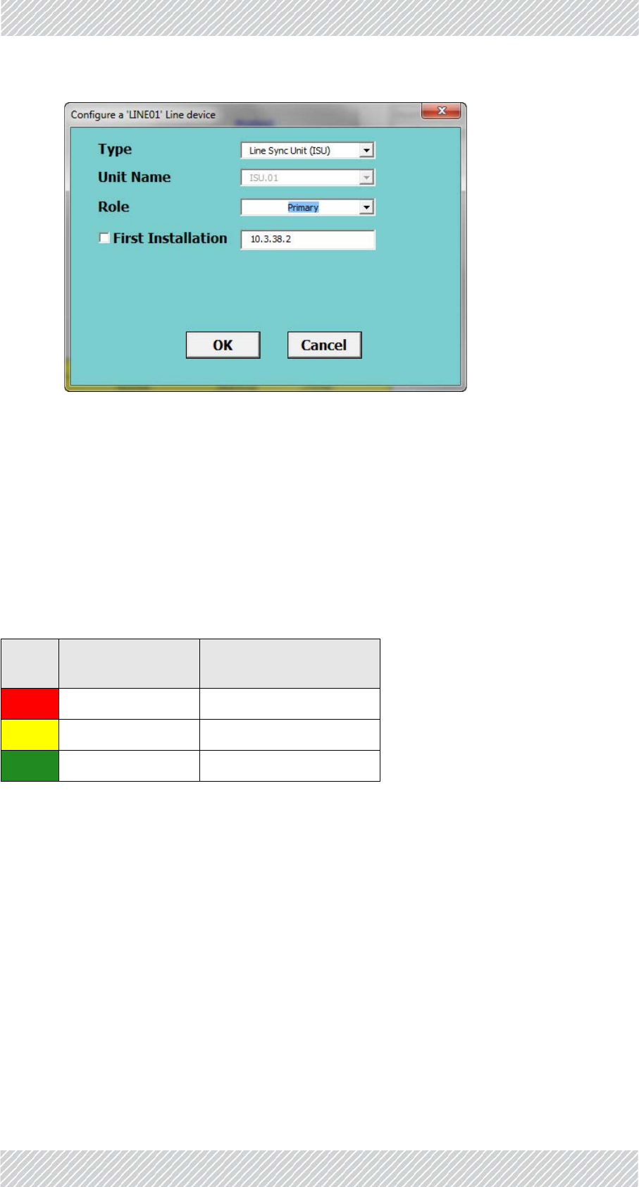
FinMDeploymentGuide Release4.5.10 4‐31
ConfiguratorMessages ConfiguringtheRadioNetwork
Figure4‐20:ISU‐Re‐configuration
3. ClickOKtocompletetheconfiguration.Itmaytakeaboutaminutetocomplete.
YouwillreceiveoneofthecompletionmessagesdescribedinConfigurator
Messagesbelow.
4.7ConfiguratorMessages
Table4‐5:ConfiguratorMessageColorCodes
Color
Code Meaning ActionRequired
Red Operationfailed Varieswithmessage
Yellow OK Repeattheoperation
Green OK Operationsuccessful

FinMDeploymentGuide Release4.5.10 4‐32
ConfiguratorMessages ConfiguringtheRadioNetwork
Ifyouareaskedtorestartthedevice,logintoitwithtelnetfollowingthisexample:
Figure4‐21:LoggingintoanTBSwithTelnet
Theusernameandpasswordarerespectively,adminandnetman.
Table4‐6:ConfiguratorMessages
Color
Code Message ActionRequired
Can'tfindConfiguration
ContactsupplierCan'tlogintodevice.Checkpassword
Failedtogetdeviceconfiguration
NoconnectionwithDevice
Ping,thencheckphysical
connection.Ifallfails,replacethe
device.
PermissionError Contactsupplier
ScriptError
TelnetConnectiontothedevicefailed
Ping,thencheckphysical
connection.Ifallfails,replacethe
device.
WrongProductConnected Checkformix‐up‐TMUforTBSor
viceversa
Pleaserunagaintocomplete.
Repeatthisconfiguration‐this
mayoccurduringasoftware
upgrade.
Configurationcompleted‐Devicerestarting... None
Configurationcompleted‐Pleaserestartdevice. LoginwithTelnetandusethe
rebootcommand(Seebelow)

FinMDeploymentGuide Release4.5.10 4‐33
ConfiguratorMessages ConfiguringtheRadioNetwork
Figure4‐22:UsingtheTelnetrebootcommandtoresetanTBS
Hereisanexample:
Table4‐7:RadioInventory
ABCMetroRadioInventory
RadioType Active Backup Total
BaseRadios 158 0 158
TrainRadios 298 0 298
SyncUnit(ISU) 448
Table4‐8:DistributionofRadioInventoryacrosslines
Line Name Base Train
5Line01 64 126
8Line02 8 20
11 Line03 38 68
1Line04 48 84
Total 158 298

FinMDeploymentGuide Release4.5.10 A‐1
AppendixA:Antenna
Guidelines
A.1ForDeploymentinUS/Canada
TheTBSandTMUdevicesbearthefollowingidentificationsontheirlabel:
ContainsFCCID:Q3K‐5XACMOD3C
ContainsIC:5100A‐5XACMD3CN
Onlytheantennasshowninthetablebeloworantennasofthesametypewithlowergainare
approvedforuseinthissystem.Theantennasmustbeinstalledsoastoprovideaminimum
separationdistancefrombystandersasspecifiedinthetablebelow:
TableA‐1:ApprovedAntennas
Cat.No. Type Gain
(dBi)
Dir
BW
Freq.
Band
(MHz)
TxPowerper
Chain
Min.Safe
Distance
(cm)
RW‐9105‐5158 DualPolarization‐
Directional 19.0 17.0° 5728‐
5850 12.0 78.0
RW‐9401‐5002 VehicularSingle‐
directional 12.5 50.0° 5728‐
5850 18.5 37.0
AT0058760 SinglePolarization‐
Directional 18.0 18.0° 5728‐
5850 13.0 70.0
RW‐9061‐5001 DualPolarization‐
Sectorial 14.0 90.0° 5728‐
5850 17.0 44.0
RW‐9061‐5002 DualPolarization‐
Sectorial 16.5 60.0° 5728‐
5850 14.5 59.0
RW‐9061‐5004 DualPolarization‐
Sectorial 11.0 120.0
°
5728‐
5850 20.0 31.0
RW‐9314‐5158 Yagi 14.0 30.0° 5728‐
5850 17.0 44.0

FinMDeploymentGuide Release4.5.10 A‐2
RW‐9401‐5004 VehicularBi‐
directional 13.0 36.0° 5728‐
5850 18.0 39.0
RW‐9401‐5007 Omni‐directional 10.0 360.0
°
5728‐
5850 21.0 28.0
RW‐9401‐5158 Omni‐directional 5.5 360.0
°
5728‐
5850 25.5 17.0
RW‐9402‐5001 Omni‐directional 10.0 360.0
°
5728‐
5850 21.0 28.0
RW‐9402‐5004 Omni‐directional 12.0 360.0
°
5728‐
5850 19.0 35.0
RW‐9521‐4958 SinglePolarization‐
Sectorial 17.0 60.0° 5728‐
5850 14.0 62.0
RW‐9531‐5001 SinglePolarization‐
Sectorial 15.0 120.0
°
5728‐
5850 16.0 50.0
RW‐9531‐5002 SinglePolarization‐
Sectorial 17.0 90.0° 5728‐
5850 14.0 62.0
TableA‐1:ApprovedAntennas(Continued)
Cat.No. Type Gain
(dBi)
Dir
BW
Freq.
Band
(MHz)
TxPowerper
Chain
Min.Safe
Distance
(cm)

FinMDeploymentGuide Release4.5.10 D‐1
RegulatoryCompliance
GeneralNote
ThissystemhasachievedTypeApprovalinvariouscountriesaroundtheworld.Thismeans
thatthesystemhasbeentestedagainstvariouslocaltechnicalregulationsandfoundto
comply.Thefrequencybandsinwhichthesystemoperatesmaybe“unlicensed”andinthese
bands,thesystemcanbeusedprovideditdoesnotcauseinterference.
FCC/ISED‐Compliance
ThisequipmenthasbeentestedandfoundtocomplywiththelimitsforaClassBdigital
device,pursuanttoPart15oftheFCCRules.Theselimitsaredesignedtoprovidereasonable
protectionagainstharmfulinterferenceinaresidentialinstallation.Thisequipment
generates,usesandcanradiateradiofrequencyenergyand,ifnotinstalledandusedin
accordancewiththeinstructions,maycauseharmfulinterferencetoradiocommunications.
However,thereisnoguaranteethatinterferencewillnotoccurinaparticularinstallation.If
thisequipmentdoescauseharmfulinterferencetoradioortelevisionreception,whichcan
bedeterminedbyturningtheequipmentoffandon,theuserisencouragedtotrytocorrect
theinterferencebyoneormoreofthefollowingmeasures:
• Reorientorrelocatethereceivingantenna.
•Increasetheseparationbetweentheequipmentandreceiver.
• Connecttheequipmentintoanoutletonacircuitdifferentfromthattowhichthe
receiverisconnected.
Consultthedealeroranexperiencedradio/TVtechnicianforhelp.
Changesormodificationstothisequipmentnotexpresslyapprovedbythepartyresponsible
forcompliancecouldvoidtheuser'sauthoritytooperatetheequipment.
RFExposure
Itisrecommendedtokeepasafedistanceof78cmfromtheradiatingantennawhen
operatingintheUSand79cmwhenoperatinginCanada.
ExpositionRF
Ilestrecommandédegarderunedistancedesécuritéde78cmdel'antennerayonnante
lorsqu'ellefonctionneauxÉtats?Unisetde79cmlorsqu'ellefonctionneauCanada
Itistheresponsibilityoftheinstallertoensurethatwhenusingthe
outdoorantennakitsintheUnitedStates(orwhereFCCrulesapply),only
thoseantennascertifiedwiththeproductareused.Theuseofany
antennaotherthanthosecertifiedwiththeproductisexpresslyforbidden
byFCCrules47CFRpart15.204.

FinMDeploymentGuide Release4.5.10 D‐2
IndoorUnitscomplywithpart15oftheFCCrules.Operationissubjecttothefollowingtwo
conditions:
(1)Thesedevicesmaynotcauseharmfulinterference.
(2)Thesedevicesmustacceptanyinterferencereceived,includinginterferencethatmay
causeundesiredoperation.
CanadianEmissionRequirementsforIndoorUnits
ThisClassBdigitalapparatuscomplieswithCanadianICES‐003.
CetappareilnumẻriquedelaclasseBestconformeảlanormeNMB‐003duCanada.
ChinaMII
OperationoftheequipmentisonlyallowedunderChinaMII5.8GHzbandregulation
configurationwithEIRPlimitedto33dBm(2Watt).
Itistheresponsibilityoftheinstallertoensurethatwhenconfiguringthe
radiointheUnitedStates(orwhereFCCrulesapply),theTxpowerisset
accordingtothevaluesforwhichtheproductiscertified.TheuseofTx
powervaluesotherthanthose,forwhichtheproductiscertified,is
expresslyforbiddenbyFCCrules47CFRpart15.204.
OutdoorunitsandantennasshouldbeinstalledONLYbyexperienced
installationprofessionalswhoarefamiliarwithlocalbuildingandsafety
codesand,whereverapplicable,arelicensedbytheappropriate
governmentregulatoryauthorities.Failuretodosomayvoidtheproduct
warrantyandmayexposetheenduserortheserviceprovidertolegaland
financialliabilities.Resellersordistributorsofthisequipmentarenot
liableforinjury,damageorviolationofregulationsassociatedwiththe
installationofoutdoorunitsorantennas.Theinstallershouldconfigure
theoutputpowerlevelofantennasaccordingtocountryregulationsand
antennatype.
•WhereOutdoorunitsareconfigurablebysoftwaretoTxpowerval‐
uesotherthanthoseforwhichtheproductiscertified,itisthe
responsibilityoftheProfessionalInstallertorestricttheTxpowerto
thecertifiedlimits.
•Thisproductwastestedwithspecialaccessories‐indoorunit(IDUor
PoE),FTPCAT‐5eshieldedcablewithsealinggasket,10AWGground‐
ingcable‐whichmustbeusedwiththeunittoinsurecompliance.

FinMDeploymentGuide Release4.5.10 D‐3
IndiaWPC
OperationoftheequipmentisonlyallowedunderIndiaWPCGSR‐38for5.8GHzband
regulationconfiguration.
Unregulated
Incountrieswheretheradioisnotregulatedtheequipmentcanbeoperatedinany
regulationconfiguration,bestresultswillbeobtainedusingUniversalregulation
configuration.
SafetyPractices
ApplicablerequirementsofNationalElectricalCode(NEC),NFPA70;andtheNational
ElectricalSafetyCode,ANSI/IEEEC2,mustbeconsideredduringinstallation.

FinMDeploymentGuide Release4.5.10 D‐4
NOTES:
1.APrimaryProtectorisnotrequiredtoprotecttheexposedwiringaslongastheexposed
wiringlengthislimitedtolessthanorequalto140feet,andinstructionsareprovidedto
avoidexposureofwiringtoaccidentalcontactwithlightningandpowerconductorsin
accordancewithNECSections725‐54(c)and800‐30.
Inallothercases,anappropriateListedPrimaryProtectormustbeprovided.RefertoArticles
800and810oftheNECfordetails.
2.ForprotectionofODUagainstdirectlightningstrikes,appropriaterequirementsofNFPA
780shouldbeconsideredinadditiontoNEC.
3.ForCanada,appropriaterequirementsoftheCEC22.1includingSection60andadditional
requirementsofCAN/CSA‐B72mustbeconsideredasapplicable.

FinMDeploymentGuide Release4.5.10 E‐1
Transportation FiberinMotion
Deployment Guide
Notice
ThishandbookcontainsinformationthatisproprietarytoRADWINLtd(RADWINhereafter).
Nopartofthispublicationmaybereproducedinanyformwhatsoeverwithoutpriorwritten
approvalbyRADWIN.
Right,titleandinterest,allinformation,copyrights,patents,know‐how,tradesecretsand
otherintellectualpropertyorotherproprietaryrightsrelatingtothishandbookandtothe
RADWINproductsandanysoftwarecomponentscontainedthereinareproprietaryproducts
ofRADWINprotectedunderinternationalcopyrightlawandshallbeandremainsolelywith
RADWIN.
TheRADWINnameisaregisteredtrademarkofRADWIN.Noright,license,orinteresttosuch
trademarkisgrantedhereunder,andyouagreethatnosuchright,license,orinterestshallbe
assertedbyyouwithrespecttosuchtrademark.
Youshallnotcopy,reversecompileorreverseassemblealloranyportionoftheDeployment
GuideoranyotherRADWINdocumentationorproducts.Youareprohibitedfrom,andshall
not,directlyorindirectly,develop,market,distribute,license,orsellanyproductthat
supportssubstantiallysimilarfunctionalitybasedorderivedinanywayfromRADWIN
products.YourundertakinginthisparagraphshallsurvivetheterminationofthisAgreement.
ThisAgreementiseffectiveuponyouropeningofaRADWINproductpackageandshall
continueuntilterminated.RADWINmayterminatethisAgreementuponthebreachbyyouof
anytermthereof.UponsuchterminationbyRADWIN,youagreetoreturntoRADWINany
RADWINproductsanddocumentationandallcopiesandportionsthereof.
ForfurtherinformationcontactRADWINatoneoftheaddressesunderWorldwideContacts
beloworcontactyourlocaldistributor.
Disclaimer
Theparametersquotedinthisdocumentmustbespecificallyconfirmedinwritingbefore
theybecomeapplicabletoanyparticularorderorcontract.RADWINreservestherightto
makealterationsoramendmentstothedetailspecificationatitsdiscretion.Thepublication
ofinformationinthisdocumentdoesnotimplyfreedomfrompatentorotherrightsof
RADWIN,orothers.
Trademarks
WinLink1000,RADWIN2000,RADWIN5000,RADWIN6000,RADWIN600and
FiberinMotionaretrademarksofRADWINLtd.
Windows2000,XPPro,Vista,Windows7andInternetExploreraretrademarksof
MicrosoftInc.
MozillaandFirefoxaretrademarksoftheMozillaFoundation.

FinMDeploymentGuide Release4.5.10 F‐1