Radwin AMWL1000 Hybrid System Tranmceiver User Manual AirMux 200 fm
Radwin Ltd. Hybrid System Tranmceiver AirMux 200 fm
Radwin >
Manual revised

AirMux
-
200
Installation and Operation
Manual
Point-to-Point
Wireless TDM/IP
Multiplexer

AirMux-200
Point-to-Point Wireless TDM/IP Multiplexer
Installation and Operation Manual
Notice
This manual contains information that is proprietary to RAD Data Communications Ltd.
("RAD"). No part of this publication may be reproduced in any form whatsoever without
prior written approval by RAD Data Communications.
Right, title and interest, all information, copyrights, patents, know-how, trade secrets
and other intellectual property or other proprietary rights relating to this manual and to
the AirMux-200 and any software components contained therein are proprietary
products of RAD protected under international copyright law and shall be and remain
solely with RAD.
AirMux-200 is a registered trademark of RAD. No right, license, or interest to such
trademark is granted hereunder, and you agree that no such right, license, or interest
shall be asserted by you with respect to such trademark.
You shall not copy, reverse compile or reverse assemble all or any portion of the Manual
or the AirMux-200. You are prohibited from, and shall not, directly or indirectly,
develop, market, distribute, license, or sell any product that supports substantially
similar functionality as the AirMux-200, based on or derived in any way from the
AirMux-200. Your undertaking in this paragraph shall survive the termination of this
Agreement.
This Agreement is effective upon your opening of the AirMux-200 package and shall
continue until terminated. RAD may terminate this Agreement upon the breach by you of
any term hereof. Upon such termination by RAD, you agree to return to RAD the AirMux-
200 and all copies and portions thereof.
For further information contact RAD at the address below or contact your local
distributor.

International Headquarters
RAD Data Communications Ltd.
24 Raoul Wallenberg St.
Tel Aviv 69719 Israel
Tel: 972-3-6458181
Fax: 972-3-6498250
E-mail: rad@rad.com
U.S. Headquarters
RAD Data Communications Inc.
900 Corporate Drive
Mahwah, NJ 07430 USA
Tel: (201) 529-1100, Toll free: 1-800-
444-7234
Fax: (201) 529-5777
E-mail: market@radusa.com
© 2002–2004 RAD Data Communications Ltd. Publication No. xxx-200-05/04
Limited Warranty
RAD warrants to DISTRIBUTOR that the hardware in the AirMux-200 to be delivered
hereunder shall be free of defects in material and workmanship under normal use and
service for a period of twelve (12) months following the date of shipment to
DISTRIBUTOR.
If, during the warranty period, any component part of the equipment becomes defective
by reason of material or workmanship, and DISTRIBUTOR immediately notifies RAD of
such defect, RAD shall have the option to choose the appropriate corrective action: a)
supply a replacement part, or b) request return of equipment to its plant for repair, or c)
perform necessary repair at the equipment's location. In the event that RAD requests
the return of equipment, each party shall pay one-way shipping costs.
RAD shall be released from all obligations under its warranty in the event that the
equipment has been subjected to misuse, neglect, accident or improper installation, or
if repairs or modifications were made by persons other than RAD's own authorized
service personnel, unless such repairs by others were made with the written consent of
RAD.
The above warranty is in lieu of all other warranties, expressed or implied. There are no
warranties which extend beyond the face hereof, including, but not limited to,
warranties of merchantability and fitness for a particular purpose, and in no event shall
RAD be liable for consequential damages.
RAD shall not be liable to any person for any special or indirect damages, including, but
not limited to, lost profits from any cause whatsoever arising from or in any way
connected with the manufacture, sale, handling, repair, maintenance or use of the
AirMux-200, and in no event shall RAD's liability exceed the purchase price of the
AirMux-200.
DISTRIBUTOR shall be responsible to its customers for any and all warranties which it
makes relating to AirMux-200 and for ensuring that replacements and other
adjustments required in connection with the said warranties are satisfactory.
Software components in the AirMux-200 are provided "as is" and without warranty of
any kind. RAD disclaims all warranties including the implied warranties of
merchantability and fitness for a particular purpose. RAD shall not be liable for any loss
of use, interruption of business or indirect, special, incidental or consequential damages
of any kind. In spite of the above RAD shall do its best to provide error-free software
products and shall offer free Software updates during the warranty period under this
Agreement.
RAD's cumulative liability to you or any other party for any loss or damages resulting from
any claims, demands, or actions arising out of or relating to this Agreement and the
AirMux-200 shall not exceed the sum paid to RAD for the purchase of the AirMux-200. In
no event shall RAD be liable for any indirect, incidental, consequential, special, or
exemplary damages or lost profits, even if RAD has been advised of the possibility of such
damages.
This Agreement shall be construed and governed in accordance with the laws of the State
of Israel.
General Safety Instructions
The following instructions serve as a general guide for the safe installation and operation
of telecommunications products. Additional instructions, if applicable, are included inside
the manual.
Safety Symbols
This symbol may appear on the equipment or in the text. It indicates
potential safety hazards regarding product operation or maintenance
to operator or service personnel.
Danger of electric shock! Avoid any contact with the marked surface
while the product is energized or connected to outdoor
telecommunication lines.
.
Protective earth: the marked lug or terminal should be connected to
the building protective earth bus.
Some products may be equipped with a laser diode. In such cases, a
label with the laser class and other warnings as applicable will be
attached near the optical transmitter. The laser warning symbol may
be also attached.
Please observe the following precautions:
• Before turning on the equipment, make sure that the fiber optic
cable is intact and is connected to the transmitter.
• Do not attempt to adjust the laser drive current.
• Do not use broken or unterminated fiber-optic cables/connectors
or look straight at the laser beam.
• The use of optical devices with the equipment will increase eye
hazard.
Warning
Warning

• Use of controls, adjustments or performing procedures other than
those specified herein, may result in hazardous radiation
exposure.
ATTENTION: The laser beam may be invisible!
Always observe standard safety precautions during installation, operation and
maintenance of this product. Only qualified and authorized service personnel should
carry out adjustment, maintenance or repairs to this product. No installation,
adjustment, maintenance or repairs should be performed by either the operator or the
user.
Handling Energized Products
General Safety Practices
Do not touch or tamper with the power supply when the power cord is connected. Line
voltages may be present inside certain products even when the power switch (if
installed) is in the OFF position or a fuse is blown. For DC-powered products, although
the voltages levels are usually not hazardous, energy hazards may still exist.
Before working on equipment connected to power lines or telecommunication lines,
remove jewelry or any other metallic object that may come into contact with energized
parts.
Unless otherwise specified, all products are intended to be grounded during normal use.
Grounding is provided by connecting the mains plug to a wall socket with a protective
earth terminal. If an earth lug is provided on the product, it should be connected to the
protective earth at all times, by a wire with a diameter of 18 AWG or wider. Rack-
mounted equipment should be mounted only in earthed racks and cabinets.
Always make the ground connection first and disconnect it last. Do not connect
telecommunication cables to ungrounded equipment. Make sure that all other cables are
disconnected before disconnecting the ground.
Connection of AC Mains
Make sure that the electrical installation complies with local codes.
Always connect the AC plug to a wall socket with a protective ground.
The maximum permissible current capability of the branch distribution circuit that
supplies power to the product is 16A. The circuit breaker in the building installation
should have high breaking capacity and must operate at short-circuit current exceeding
35A.
Always connect the power cord first to the equipment and then to the wall socket. If a
power switch is provided in the equipment, set it to the OFF position. If the power cord
cannot be readily disconnected in case of emergency, make sure that a readily
accessible circuit breaker or emergency switch is installed in the building installation.
Connection of DC Mains
Unless otherwise specified in the manual, the DC input to the equipment is floating in
reference to the ground. Any single pole can be externally grounded.
Due to the high current capability of DC mains systems, care should be taken when
connecting the DC supply to avoid short-circuits and fire hazards.
DC units should be installed in a restricted access area, i.e. an area where access is
authorized only to qualified service and maintenance personnel.
Make sure that the DC supply is electrically isolated from any AC source and that the
installation complies with the local codes.
The maximum permissible current capability of the branch distribution circuit that
supplies power to the product is 16A. The circuit breaker in the building installation
should have high breaking capacity and must operate at short-circuit current exceeding
35A.
Before connecting the DC supply wires, ensure that power is removed form the DC
circuit. Locate the circuit breaker of the panel board that services the equipment and
switch it to the OFF position. When connecting the DC supply wires, first connect the
ground wire to the corresponding terminal, then the positive pole and last the negative
pole. Switch the circuit breaker back to the ON position.
A readily accessible disconnect device that is suitably rated and approved should be
incorporated in the building installation.
Installing the Radio Terminals (RTs)
The following safety measures apply when installing the radio terminals and masts.
• Mast / pole / towers should comply with local standards such as BS6651.
• Only trained professional installers should install or dismantle radio terminals and
masts. The installer is responsible for meeting all building and safety codes.
• Before installing a terminal, make sure it is disconnected from power.
• A safety belt and climbing harness must be used when installing the radio terminals
on a mast or tower.
• Masts of height 3 meters or more must be guyed according to required industry
standards and be lightning protected.
• If a radio terminal is to be mounted at a height of more than 4 meters above the
roof, it is recommended that a climbable tower be installed to give access to the
equipment and to prevent antenna movement during strong winds.
• When installing equipment, beware of overhead high-voltage power lines. Never
install a mast under power lines.
• The mast structure must be grounded.
• Do not stand in front of a live radio terminal.
• The installer should configure the output power level of antennas according to
country regulations and per antenna type.
• The antenna used for this transmitter must be installed to provide a separation
distance of at least 200 cm from all persons and must not be co-located or
operating in conjunction with any other antenna or transmitter.

Outdoor units and antennas should be installed ONLY by experienced
installation professionals who are familiar with local building and
safety codes and, wherever applicable, are licensed by the
appropriate government regulatory authorities. Failure to do so may
void the AirMux-200 warranty and may expose the end user or the
service provider to legal and financial liabilities. RAD and its resellers
or distributors are not liable for injury, damage or violation of
regulations associated with the installation of outdoor units or
antennas.
Protection Against Lightning Activity
Observe the following safety measures to protect personnel and equipment:
• All outdoor equipment must be attached to a properly grounded structure, and
installed masts must be grounded, in order to provide protection against lightening,
surges and static buildup. In addition, mast over 3 meters should have a lightning
protection rod. Failure to do so creates a safety risk and will void the equipment
warranty.
• Do not work on the system or connect or disconnect the cables prior to or during
electrical storm activity.
• In case of an electrical storm, do not touch any outdoor electrical equipment and
leave the roof as quickly as possible.
Warning

Connection of Data and Telecommunications Cables
Data and telecommunication interfaces are classified according to their safety status.
The following table lists the status of several standard interfaces. If the status of a given
port differs from the standard one, a notice will be given in the manual.
Ports Safety Status
V.11, V.28, V.35, V.36, RS-530,
X.21, 10 BaseT, 100 BaseT,
Unbalanced E1, E2, E3, STM, DS-
2, DS-3, S-Interface ISDN,
Analog voice E&M
SELV Safety Extra Low Voltage:
Ports which do not present a safety hazard.
Usually up to 30 VAC or 60 VDC.
xDSL (without feeding voltage),
Balanced E1, T1, Sub E1/T1 TNV-1 Telecommunication Network Voltage-1:
Ports whose normal operating voltage is
within the limits of SELV, on which overvoltages
from telecommunications networks are possible.
FXS (Foreign Exchange
Subscriber) TNV-2 Telecommunication Network Voltage-2:
Ports whose normal operating voltage
exceeds the limits of SELV (usually up to 120 VDC
or telephone ringing voltages), on which
overvoltages from telecommunication networks
are not possible. These ports are not permitted
to be directly connected to external telephone and
data lines.
FXO (Foreign Exchange Office),
xDSL (with feeding voltage),
U-Interface ISDN
TNV-3 Telecommunication Network Voltage-3:
Ports whose normal operating voltage
exceeds the limits of SELV (usually up to 120 VDC
or telephone ringing voltages), on which
overvoltages from telecommunication networks
are possible.
The signals between the IDU and ODU are TNV-1.
Always connect a given port to a port of the same safety status. If in doubt, seek the
assistance of a qualified safety engineer.
Note
Always make sure that the equipment is grounded before connecting telecommunication
cables. Do not disconnect the ground connection before disconnecting all
telecommunications cables.
Some SELV and non-SELV circuits use the same connectors. Use caution when
connecting cables. Extra caution should be exercised during thunderstorms.
When using shielded or coaxial cables, verify that there is a good ground connection at
both ends. The earthing and bonding of the ground connections should comply with the
local codes.
The telecommunication wiring in the building may be damaged or present a fire hazard
in case of contact between exposed external wires and the AC power lines. In order to
reduce the risk, there are restrictions on the diameter of wires in the telecom cables,
between the equipment and the mating connectors.

To reduce the risk of fire, use only No. 26 AWG or larger telecommunication
line cords.
Pour réduire les risques s’incendie, utiliser seulement des conducteurs de
télécommunications 26 AWG ou de section supérieure.
Some ports are suitable for connection to intra-building or non-exposed wiring or
cabling only. In such cases, a notice will be given in the installation instructions.
Do not attempt to tamper with any carrier-provided equipment or connection hardware.
Electromagnetic Compatibility (EMC)
The equipment is designed and approved to comply with the electromagnetic
regulations of major regulatory bodies. The following instructions may enhance the
performance of the equipment and will provide better protection against excessive
emission and better immunity against disturbances.
A good earth connection is essential. When installing the equipment in a rack, make
sure to remove all traces of paint from the mounting points. Use suitable lock-washers
and torque. If an external grounding lug is provided, connect it to the earth bus using
braided wire as short as possible.
The equipment is designed to comply with EMC requirements when connecting it with
unshielded twisted pair (UTP) cables. However, the use of shielded wires is always
recommended, especially for high-rate data. In some cases, when unshielded wires are
used, ferrite cores should be installed on certain cables. In such cases, special
instructions are provided in the manual.
Disconnect all wires which are not in permanent use, such as cables used for one-time
configuration.
The compliance of the equipment with the regulations for conducted emission on the
data lines is dependent on the cable quality. The emission is tested for UTP with 80 dB
longitudinal conversion loss (LCL).
Unless otherwise specified or described in the manual, TNV-1 and TNV-3 ports provide
secondary protection against surges on the data lines. Primary protectors should be
provided in the building installation.
The equipment is designed to provide adequate protection against electro-static
discharge (ESD). However, it is good working practice to use caution when connecting
cables terminated with plastic connectors (without a grounded metal hood, such as flat
Caution
Attention

cables) to sensitive data lines. Before connecting such cables, discharge yourself by
touching earth ground or wear an ESD preventive wrist strap.
FCC-15 User Information
This equipment has been tested and found to comply with the limits for a
Class B digital device, pursuant to Part 15 of the FCC Rules. These limits
are designed to provide reasonable protection against harmful interference
in a residential installation. This equipment generates, uses and can
radiate radio frequency energy and, if not installed and used in accordance
with the instructions, may cause harmful interference to radio
communications. However, there is no guarantee that interference will not
occur in a particular installation. If this equipment does cause harmful
interference to radio or television reception, which can be determined by
turning the equipment off and on, the user is encouraged to try to correct
the interference by one or more of the following measures:
-- Reorient or relocate the receiving antenna.
-- Increase the separation between the equipment and receiver.
-- Connect the equipment into an outlet on a circuit different
from that to which the receiver is connected.
Consult the dealer or an experienced radio/TV technician for help.
Changes or modifications to this equipment not expressly approved by the party
responsible for compliance (RAD) could void the user’s authority to operate the
equipment.
It is the responsibility of the installer to ensure that when using the
outdoor antenna kits in the United States (or where FCC rules apply),
only those antennas certified with the product are used. The use of
any antenna other than those certified with the product is expressly
forbidden in accordance to FCC rules CFR47 part 15.204.
Warning

Canadian Emission Requirements for the IDU
This Class A digital apparatus meets all the requirements of the Canadian Interference-
Causing Equipment Regulation.
Cet appareil numérique de la classe A respecte toutes les exigences du Règlement sur le
matériel brouilleur du Canada.
Warning per EN 55022 (CISPR-22) for the IDU
This is a class A product. In a domestic environment, this product
may cause radio interference, in which case the user will be required
to take adequate measures.
Cet appareil est un appareil de Classe A. Dans un environnement
résidentiel, cet appareil peut provoquer des brouillages
radioélectriques. Dans ces cas, il peut être demandé à l’utilisateur de
prendre les mesures appropriées.
Dieses ist ein Gerät der Funkstörgrenzwertklasse A. In Wohnbereichen
können bei Betrieb dieses Gerätes Rundfunkströrungen auftreten, in
welchen Fällen der Benutzer für entsprechende Gegenmaßnahmen
verantwortlich ist.
Statement according to Directive 1999/5/EC
Hereby, RAD Data Communications Ltd. declares that the AirMux-200 system is in
compliance with the essential requirements and other relevant provisions of Directive
1995/5/EC.
The alert sign on the AirMux-200 indicates that the frequency band that is being
used by the equipment is not harmonized within the EU and/or the potential
restrictions on its use are applicable in one or more EU member states.
Warning
Avertissement
Achtung

Installing AirMux-200 Units 1
Quick Start Guide
Installation of AirMux-200 should be carried out only by a qualified
technician. If you are familiar with AirMux-200, use this guide to prepare
the units for operation.
1. Installing AirMux-200 Units
ODU Package Contents:
§ ODU
§ Mast/Wall mounting kit
§ Mounting instructions
§ RJ-45 Connector
§ Hermetic Cable Enclosure
§ AIRMUX-200 Manager installation CD
IDU Package Contents:
§ IDU
§ RJ-45 Connector
§ Wall mounting drilling template
§ 110V/220V desk mount adaptor
Equipment Required:
§ RJ-45 Crimp Tool
§ Wall mounting hardware. Ordered separately
(To wall mount IDU, use screws with head diameter of 6.3mm
max)
§ Drill
§ IDU grounding cable
§ 13 mm or 1/2” socket spanner

Quick Start Guide AirMux-200 Installation and Operation Manual
2 Installing AirMux-200 Units
§ ODU/IDU Cable (Outdoor class, CAT-5e, 4 twisted pairs)
§ UV-rated cable ties
§ Laptop running Windows 2000 or Windows XP
Before the installation
1. Install the AirMux-200 software on the laptop.
2. Verify that all equipment and tools are available
Performing Outdoor Installation
ä To install the ODU:
1. Route the ODU cable from the ODU location (on the roof) to the IDU
location (inside the building).
2. Mount the ODU unit to the mast or wall, using the mounting kit.
3. Connect the RJ-45 connectors to both ends of the cable, use the
pinout table below:
IDU RJ-45 Wire Color ODU RJ-45 Function
1 White/Green 1
Twisted 2 Green 2
3 White/Orange 3
Twisted 6 Orange 6
Ethernet
4 Blue 4
Twisted 5 White\Blue 5
7 White/Brown 7
Twisted 8 Brown 8
Power
4. Secure the ODU and ground cables to the mast or brackets using
UV-rated cable ties.
5. Repeat the procedure at the remote site.
ä To align the ODU:
1. Connect power to the IDU.
Warning

AirMux-200 Installation and Operation Manual Quick Start Guide
Operating AirMux-200 3
Do not stand in front of a live radio terminal.
2. Align the local ODU in the direction of the remote ODU. Turn the ODU
slowly using the buzzer beep sequence until optimal alignment is
achieved:
3. Repeat step 2 for the remote ODU to complete the alignment
procedure.
4. Make sure that the management station is properly connected to the
local IDU, and the AirMux Manager application is running.
5. Open the installation wizard and follow the installation steps
6. After selection of the radio channel and the link rate, verify the link
quality is at least in the yellow area for Ethernet service and in the
green area for TDM service.
Try to achieve the best possible link quality values. In case of radio link
loss, verify the ODU alignment, or change the radio channel in both sides
of the link. When the radio link resumes continue the installation process.
7. Monitor the link quality for about 15 minutes to verify stability.
8. Permanently attach the local and remote ODU to the mast/wall.
Performing Indoor Installation
ä To connect user equipment to the IDU:
1. Connect user mux or PBX to the IDU rear panel RJ-45 port designated
Trunk.
2. Connect user hub/router or any other compatible device to the IDU
rear-panel RJ-45 port designated LAN.
2. Operating AirMux-200
AirMux-200 requires no operator attention once installed, with the
exception of occasional monitoring of front panel indicators and statistics
data. Intervention is only required when AirMux-200 must be configured
to its operational requirements or diagnostic tests are performed.
Note

Quick Start Guide AirMux-200 Installation and Operation Manual
4 Operating AirMux-200
Normal Indications
Upon turning on AirMux-200, the PWR LED in the front panel lights to
indicate that AirMux-200 is on. The table below shows the correct status
of the indicators a few seconds after power-up.
Indicator Status
PWR ON
RTCB Green – Blinking
slowly
RT Green – Blinking
slowly
Air Green – Blinking
slowly
Service Green – Blinking
slowly
Troubleshooting
1. PWR LED is off – Check that AC adapter is connected to the IDU
and the AC power outlet
2. RTCB LED is yellow – Check that the IDU/ODU cable is properly
wired and connected
3. RT LED is red – Check that the IDU/ODU cable is properly wired
and connected
4. Air LED is yellow – Complete the installation procedure from the
management software.
5. Air LED is RED – Check the ODU Antenna alignment. Check that the
radio configuration of both local and remote units are the same
(channel and SSID)
6. Service LED is off – Check the TDM service configuration in the
NMS
7. Service LED is yellow – Check that the system is not in loop-back
mode. Check the remote RTCB ports and cables and remote
external equipment.
8. Service led is red – check the local IDU ports, cables and external
equipment
Overview 1-1
Chapter 1
Introduction
1.1 Overview
AirMux-200 is a carrier-class, high capacity, low cost Point-to-Point
broadband wireless transmission system. AirMux-200 packs Legacy TDM
and Ethernet services over 5.725-5.850 GHz license-exempt bands and
is suitable for deployment in FCC or ESTI regulated countries over a 48
Mbps wireless link at distances of up 80 km (50 miles).
Application
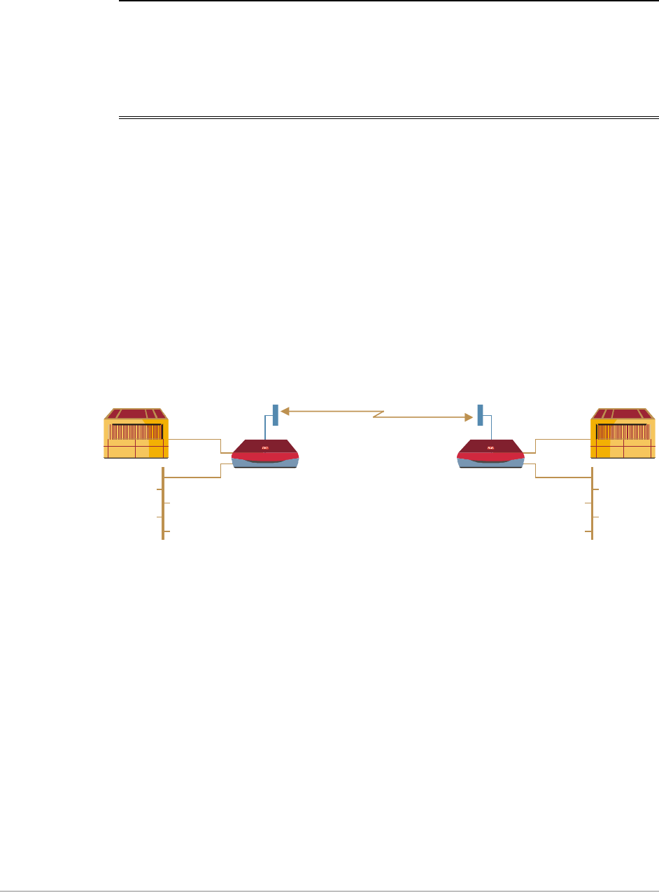
Figure 1-1 illustrates a typical point-to-point application of two
AirMux-200 units.
PBX
LAN
LAN
EthernetEthernet
AirMux-200
Up to 80 km (50 miles)
AirMux-200 PBX
E1/T1
E1/T1
Figure 1-1. Typical Application
Features
Wireless Link
AirMux-200 delivers a 48 Mbps channel for Ethernet traffic, excluding
inband (TDMoIP) E1/T1 streams. AirMux-200 operates as a line-of-
sight radio system supporting the following frequency bands:
• ANSI Unlicensed National Information Infrastructure (UNII)
• ISM.

Chapter 1 Introduction AirMux-200 Installation and Operation Manual
1-2 Overview
AirMux-200 can be configured to operate over several frequency
channels with a carrier step resolution of 10 MHz. The number of the
frequency channels depends on the selected operating band.
AirMux-200 uses Direct Sequence Spread Spectrum technology
combined with powerful forward error correction to ensure high
reliability and security over license exempt 5.725–5.850 GHz
frequencies. AirMux-200 operation complies with the FCC
15.401&15.407 requirements.
AirMux-200 employs Time Division Duplex (TDD) transmission. This
technology simplifies the installation and configuration procedure.
There is no need to plan and to allocate separate channels for the
uplink and downlink data streams.
Operation over 5.725–5.850 GHz bands is not affected by harsh
weather conditions, such as fog, heavy rain etc.
LAN Interface
The AirMux-200 LAN port provides two 10/100BaseT interfaces with
autonegotiation and transparent VLAN support. Traffic handling is
provided by a MAC-level self-learning bridge.
TDM Interface
The AirMux-200 TDM interface accepts E1 or T1 traffic, supporting the
following:
• Framed and unframed operation (E1 and T1)
• ESF and SF framing (T1)
• AMI and B8ZS zero suppression (T1)
• CRC-4 bits generation (E1)
• Flexible timeslot allocation (framed E1 and T1).
Management
AirMux-200 has full local and remote management capabilities. The
user-friendly SNMP-based management tool provides full end-to-end
configuration and performance monitoring capabilities.
Diagnostics and Performance Monitoring
AirMux-200 supports activating local and remote loopbacks on E1 or
T1 links.

AirMux-200 Installation and Operation Manual Chapter 1 Introduction
Overview 1-3
AirMux-200 constantly monitors the data transmission process,
evaluates received signal strength, signal-to-noise ratio and bit error
rate. It also monitors received traffic and frame rate (FPS) for local and
remote units.
Optional External Antenna
An optional planar array 28 dBi external antenna increases the
operation range of AirMux-200 to 80 km (50 miles).
Chapter 1 Introduction AirMux-200 Installation and Operation Manual
1-4 Physical Description
1.2 Physical Description
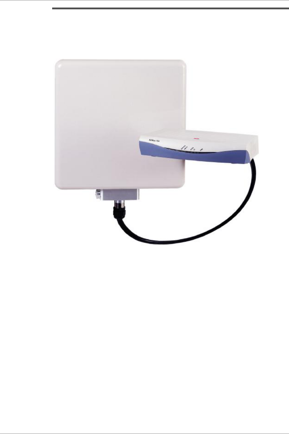
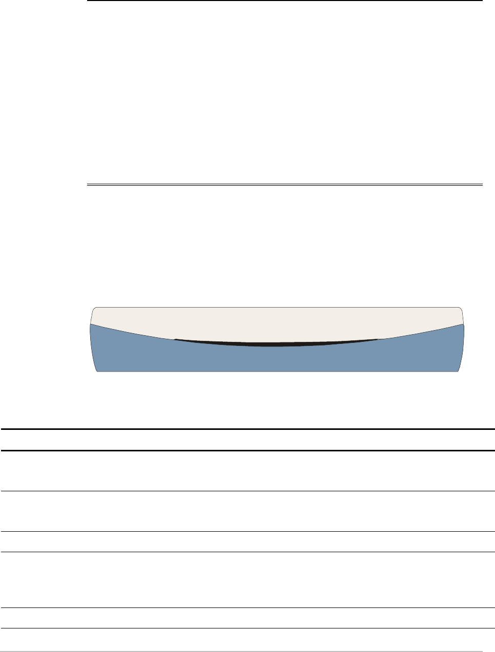
AirMux-200 system consists of a radio terminal (ODU) and an indoor
unit (IDU). Figure 1-2 illustrates an AirMux-200 unit assembly.
Figure 1-2. AirMux-200 Unit
The front panel of the indoor unit (IDU) includes five LEDs, which
display the status of E1/T1, wireless link, self-test results, ODU-to-IDU
link, and power status. For a detailed description of the front panel,
see Chapter 4.
The rear panel of the indoor unit (IDU) includes the power, user (WAN,
LAN and E1 or T1), and radio terminal connectors. The AirMux-200
rear panel is described in detail in Chapter 3.

AirMux-200 Installation and Operation Manual Chapter 1 Introduction
Technical Specifications 1-5
1.3 Technical Specifications
Wireless Link
Technology Spread spectrum
Frequency Band 5.725–5.850 GHz:
• ANSI Unlicensed National Information
Infrastructure (UNNII)
• ISM
Duplexing Method Time Division Duplex (TDD)
Capacity Configurable up to 48 Mbps (See Table 1-1)
Modulation OFDM - BPSK, QPSK, 16QAM, 64QAM
Channel Bandwidth
Resolution 10 MHz
Transmitter Power FCC: 21.4 dBm max
ETSI: 7 dBm max (limited by ETSI regulations)
Receiver Sensitivity –90 dBm at BER 1E-8
Antenna Gain 22 dBi
Antenna Beam ±9° horizontal and vertical
Range 80 km (50 miles), including 6 dB fade margin
ODU Installation
Method Mast or wall mounting
LAN Interface
PHY IF 10/100BaseT, auto-sensing
Framing/Coding IEEE 802.3/U
Bridging Self-learning, up to 2000 MAC addresses
Line Impedance 100Ω
VLAN Support Transparent
Data Rate 48 Mbps max.
Connector RJ-45
E1 Interface
Framing G.703, G.704 with or without CRC
Data Rate Unframed (Transparent) 2.048MHz

Chapter 1 Introduction AirMux-200 Installation and Operation Manual
1-6 Technical Specifications
Timing Plesiochronous
Connector RJ-45
T1 Interface
Zero Suppression AMI, B8ZS
Framing SF, ESF
Connector RJ-45

AirMux-200 Installation and Operation Manual Chapter 1 Introduction
Technical Specifications 1-7
External
Antenna
Type Planar array
Gain 28 dBi min
VSWR 1.7:1 max
F/B Ratio -40 dB max
Compliance ETSI EN 302 085 V1.1.2 (2001-02)
Polarization Linear (vertical or horizontal)
Input Impedance 50Ω
Lightning
Protection DC-grounded
Connector N-type, female
Range Up to 80 km (50 miles), including 6 dB fade
margin
Indicators PWR (green) Power status
ODU (green/red) ODU-to-IDU link status
IDU (green) IDU self-test results
AIR I/F (green/red) Wireless link status
Service (green/red) E1/T1 signal status
Power Source 100–240 VAC via external AC/DC converter
Power Received by
the ODU (PoE) -48 VDC
Power Consumption
20W max (ODU and IDU)
Connector 2-pin
Physical Outdoor Unit (ODU) with integrated antenna
Height 305 mm / 12 in
Width 305 mm / 12 in
Depth 58 mm / 2.3 in
Weight 3.3 kg / 7.2 lb
Indoor Unit (IDU-E)

Chapter 1 Introduction AirMux-200 Installation and Operation Manual
1-8 Technical Specifications
Height 44 mm / 1.7 in (1U)
Width 237 mm / 9.3 in
Depth 170 mm / 6.7 in
Weight 0.58 kg / 1.4 lb

AirMux-200 Installation and Operation Manual Chapter 1 Introduction
Technical Specifications 1-9
External Antenna
(Optional)
Height 600 mm / 23.6 in
Width 600 mm / 23.6 in
Depth 51 mm / 2 in
Weight 5 kg / 11 lb
Environment
Outdoor Unit (ODU)
Enclosure All-weather case
Temperature -35 to 60°C/-31 to 140°F
Indoor Unit (IDU)
Temperature -5 to 45°C/23 to 113°F
Humidity Up to 90%, non-condensing
Table 1-1. Throughput/Capacity
Rate (MHz) Throughput
Mbps at 5km
full duplex
Capacity
E1 T1 Integrated
Antenna
(km)
External
Antenna
(km)
12 4.5 1 1 26 40
18 7 2 2 18 40
36 13 2 2 8 26
48 17 2 2 3 9
AirMux-200 System 2-1
Chapter 2
Installation and Setup
This chapter describes installation and setup procedures for AirMux-
200 system.
After installing the unit, refer to Chapter 3 for configuration
instructions.
In case a problem is encountered, refer to Chapter 5 for test and
diagnostic instructions.
Internal settings, adjustment, maintenance, and repairs may be
performed only by a skilled technician who is aware of the hazards
involved.
Always observe standard safety precautions during installation,
operation, and maintenance of this product.
2.1 AirMux-200 System
AirMux-200 system comprises the following units:
• Outdoor Unit (ODU): An enclosed aluminum frame with a front
sealed plastic cover, containing an integrated transceiver with an
antenna, RF module, modem and standard interfaces. The ODU
stores all the configuration parameters of the AirMux-200 system.
ODU includes a power connector, which receives -48 VDC, and RJ-
45 for Ethernet (including PoE) traffic from the indoor unit (IDU).
The ODU is attached to a mast using a special mounting kit, which
is supplied with the unit.
• Indoor Unit (IDU): The interface unit between the ODU and the user.
It converts 220 VAC to -48VDC, and sends it on to the ODU. The
IDU does not store any configuration data. Therefore there is no
need for additional configuration of the AirMux-200 system when
replacing an IDU.
Warning

Chapter 2 Installation and Setup AirMux-200 Installation and Operation Manual
2-2 Installation and Setup
2.2 Site Requirements and Prerequisites
For the IDU, allow at least 90 cm (36 in) of frontal clearance for
operating and maintenance accessibility. Allow at least 10 cm (4 in)
clearance at the rear of the unit for signal lines and interface cables.
The ambient operating temperature should be –45 to 60°C/-49 to
140°F (ODU), or -5 to 45°C/23 to 113°F (IDU) at a relative humidity of
up to 90%, non-condensing.
2.3 Package Contents
The AirMux-200 package includes the following items:
• ODU (Outdoor Unit)
• IDU (Indoor Unit)
• ODU cable pre-cut to length ordered
• Two spare RJ-45 connectors
• AC/DC power converter
• AirMux Manager installation CD
• Technical documentation CD
• ODU mounting kit
• External antenna (if ordered)
2.4 Installation and Setup
Physical installation of the AirMux-200 system includes the following
steps:
1. Installing management program on the network management
station.
¨ Selecting IP address, subnet mask, default gateway and trap
destination.
AirMux-200 Installation and Operation Manual Chapter 2 Installation and Setup
Installation and Setup 2-3
2. Installing Outdoor Unit (ODU) and Indoor Unit (IDU) at the local and
remote sites.
3. Installing ODU cable and connecting ODU and IDU at the local and
remote sites.
4. Aligning local and remote ODUs.
5. Connecting user equipment to the local and remote IDUs.
6. Connecting power.
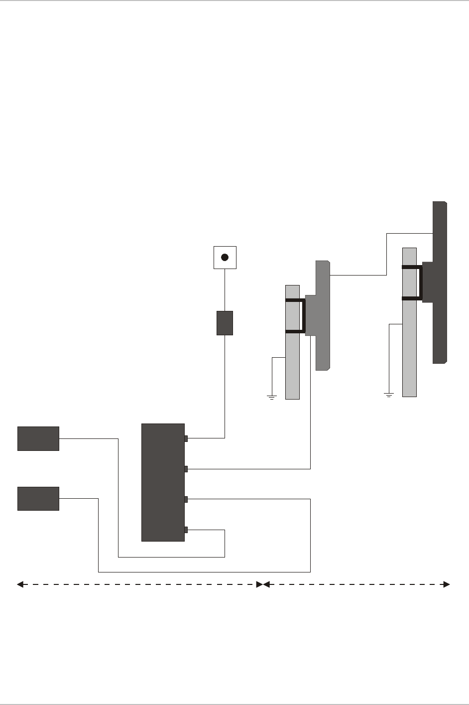
Figure 2-1 illustrates a typical installation of AirMux-200 with external
antenna.
Circuit
Breaker
16A
ODU
Coaxial RF
Cable
External
Antenna
220 VAC
AC/DC
Converter
IDU
-48 VDC
Mux/PBX
Hub/Router
Ethernet
E1
RT Cable (100m max)
(Ethernet, E1, -48 VDC)
Indoor
Outdoor
Figure 2-1. Typical Installation Diagram
Chapter 2 Installation and Setup AirMux-200 Installation and Operation Manual
2-4 Installation and Setup
Installing AirMux-200 Management Software
AirMux-200 management application is distributed on CD-ROM as an
executable file. The application operates on a PC under any
Windows 98/2000/NT/XP operating system.
ä To install the AirMux-200 management program:
1. Insert the CD-ROM into your CD-ROM drive.
2. Run Airmux.exe from the CD-ROM drive.
3. Follow the onscreen instructions of the installation wizard to
complete setup of the AirMux-200 management program in the
desired location.
Connecting the ODU to the IDU
The ODU cable conducts all the user traffic between the IDU and the
ODU. The ODU cable also provides -48 VDC supply to the ODU. The
maximum length for one leg of the ODU cable is 100m (328 ft).
The ODU cable is supplied assembled with RJ-45 connectors, at the
length specified when ordering. Spare RJ-45 connectors are supplied
for use if necessary.
1. Route the cable from the ODU location into the building, leaving
some spare. Secure the cable along its path.
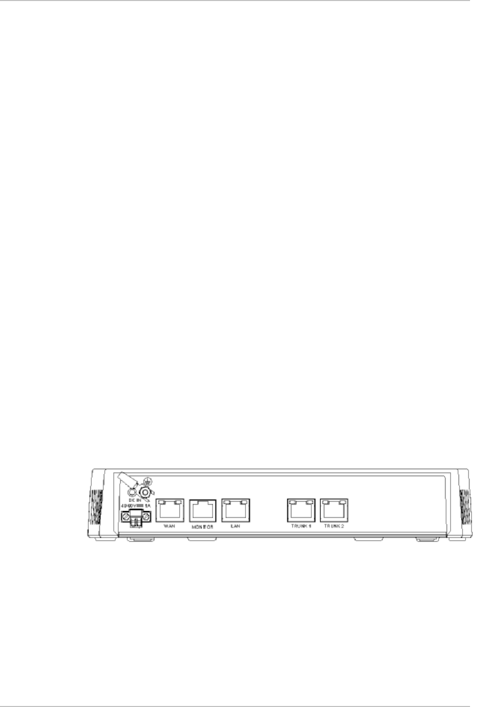
2. Connect the ODU cable to the RJ-45 connector on the IDU rear
panel designated WAN. Figure 2-2 illustrates a typical panel of the
IDU.
Figure 2-2. IDU Rear Panel
Mounting and Aligning the ODU
The ODU is the transmitting and receiving element of the AirMux-200
system. The ODU can be mounted on a mast or a wall. In both
installations, the supplied mounting kit is used to secure the ODU.
Appendix B describes the mast/wall installation instructions.

AirMux-200 Installation and Operation Manual Chapter 2 Installation and Setup
Installation and Setup 2-5
An AirMux-200 link operates in pairs of two AirMux-200 systems with
the same configuration. Both systems must be installed, and the
antennas of the outdoor units must be aligned for maximum
throughput.
You can verify that the AirMux-200 ODU units are aligned using a
DVM-tool or the Buzzer located inside the ODU. Alternatively, this can
be done via the AirMux management software.
Prior to connecting cables to the ODU, the protective earth terminal
(screw) of the ODU must be connected to an external protective ground
conductor or to a grounded mast.
Only a qualified person using the proper safety equipment should
climb the antenna mast. Only trained professional installers should be
used when installing or dismantling ODUs and masts.
ä To install the ODU:
1. Verify that the ODU mounting brackets are properly grounded.
2. Attach the ODU unit to the mast, using the two strap clamps. Refer
to Appendix B for the ODU mounting instructions.
3. Connect the ground cable to the chassis point on the ODU.
4. Attach the ODU cable to the RJ-45 connector. Refer to Appendix A
for the connector pinout.
5. Secure the cables to the mast or brackets using provided UV-rated
cable ties.
6. Repeat the procedure at the remote site.
Do not tightly secure the ODU to its mounting brackets, if the
alignment process of the antenna is not yet complete.
When installing the ODU, it is important to check that there are no
direct obstructions in front of the ODU or interference from man-made
obstacles.
ä To align the ODUs via ODU Buzzer:
1. Connect power to the IDUs.
Warning
Note
Chapter 2 Installation and Setup AirMux-200 Installation and Operation Manual
2-6 Installation and Setup
Do not stand in front of a live radio terminal.
2. Turn the local ODU in the direction of the remote ODU.
3. At the remote site, turn the ODU to face the local ODU. (Align
visually or by using a map and a compass). Use the DVM-tool or
Buzzer indication on the ODU to verify link quality (see Figure 2-3).
4. Repeat step 3 for the local ODU to complete the installation
procedure.
5. Slowly adjust the ODU at both sites until you hear the Best Signal
sound.
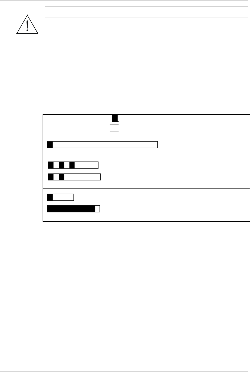
Buzzer Sequence
=buzzer on
=buzzer off
Description
Radio is on but no radio link
to the remote side
Best Signal so far
Signal better than the last
second
Signal same as the last second
Signal worse than the last
second
Figure 2-3. Buzzer Sequence for ODU Alignment
Warning

AirMux-200 Installation and Operation Manual Chapter 2 Installation and Setup
Installation and Setup 2-7
ä To align the ODUs using the AirMux Manager:
1. Connect power to the IDUs.
Do not stand in front of a live radio terminal.
2. Turn the local ODU in the direction of the remote ODU.
3. At the remote site, turn the ODU to face the local ODU. (Align
visually or by using a map and a compass).
4. Repeat step 3 for the local ODU to complete the installation
procedure.
5. Make sure that the management station is properly connected to
the same LAN as the IDU, and the AirMux Manager application is
running.
6. In the Main menu, click Monitor.
Once the wireless link is established between the local and
remote units, the Link Status indication bar in the middle of the
Main menu turns green. In addition, Radio Link - Sync message
appears in the logger at the bottom of the Main menu.
7. Check the radio signal strength (RSS) and sound-to-noise ratio
(SNR) in the Main menu. Rotate the local ODU until the best RSS is
found (better than -88 dBm). The SNR should be at least 9 dB.
Monitor these parameters for about 15 minutes to verify stability.
Try to achieve the best possible RSS and SNR values.
8. After achieving the best RSS and SNR levels, permanently attach the
ODU to the mast. Refer to Appendix B for the ODU mounting
instructions.
Connecting the User Equipment
The IDU is a standalone desktop, wall-mounted or rack-installed unit.
Figure 2-2 illustrates a typical rear panel of the IDU.
ä To connect user equipment to the IDU:
1. Connect a user mux or PBX to the IDU rear panel RJ-45 port
designated Trunk. Refer to Appendix A for the connector pinout.
Note
Warning

Chapter 2 Installation and Setup AirMux-200 Installation and Operation Manual
2-8 Installation and Setup
2. Connect user hub/router or any other compatible device to the IDU
rear panel RJ-45 port designated LAN. Refer to Appendix A for the
connector pinout.
Use a straight cable for router connection.
Connecting the Power
Before connecting any cable, the protective earth terminals of the
AC/DC adapter must be connected to the protective ground conductor
of the mains power cord. If you are using an extension cord (power
cable) make sure it is grounded as well.
Any interruption of the protective (grounding) conductor (inside or
outside the instrument) or disconnecting of the protective earth
terminal can make this unit dangerous. Intentional interruption is
prohibited.
Power is supplied to AirMux-200 via an external AC/DC converter,
which receives power from 100–240 VAC source and converts it to -48
VDC.
ä To connect the power:
1. Connect the 2-pin plug of the AC/DC converter to the 2-pin DC
power connector on the IDU rear panel.
2. Connect the AC/DC converter 3-prong plug to the mains outlet.
The unit turns on automatically upon connection to the mains.
Note
Warning

Performing Configuration of AirMux-200 3-1
Chapter 3
Configuration
This chapter describes configuration procedures, which is performed
after the physical installation of the local and remote AirMux-200
units.
3.1 Performing Configuration of AirMux-200
After physical installation of the local and remote AirMux-200 units,
perform initial configuration of the system.
ä To perform initial setup:
1. Power up the local IDU (see Connecting the Power in Chapter 2).
Wait for about 1 minute.
2. Power up the remote IDU.
3. Connect the management station to the LAN.
Any PC running the AirMux-200 management application can be used
to configure AirMux-200 units.
ä To start AirMux manager:
1. From the Start menu, point to Programs, point to AirMux Manager,
and then click AirMux Manager.
The password/IP request dialog appears.
2. Enter IP + password – airmux.
The AirMux Manager Main menu is displayed (see Figure 3-1).
The system is factory installed with the settings of the system ordered,
therefore the Install Link button is disabled.
Note
Chapter 3 Configuration AirMux-200 Installation and Operation Manual
3-2 Performing Configuration of AirMux-200
Figure 3-1. AirMux Manager Main Menu
AirMux-200 Installation and Operation Manual Chapter 3 Configuration
Performing Configuration of AirMux-200 3-3
Configuring General Parameters
In order to establish a link between the manager station and AirMux-
200 you must configure the link channel and rate parameters.
ä To change general parameters:
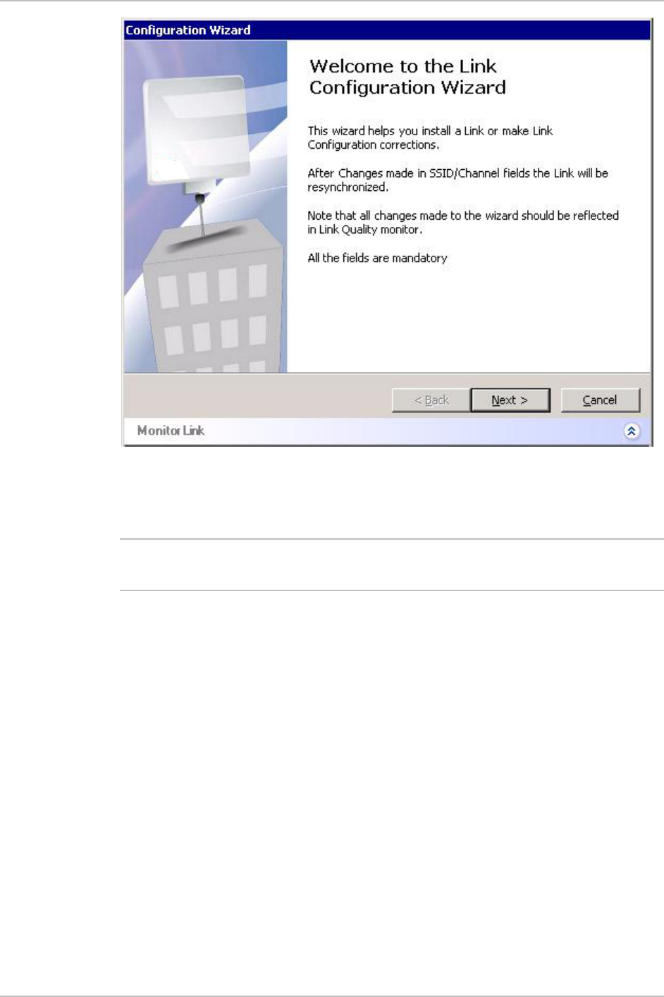
1. In the Main menu, click Configure Link.
2. The Configuration Wizard opens.
The wizard is used to install a link or make configuration
changes.
When the SSID or Channel fields are changed, the link is reset.
All changes made in the wizard are reflected in the Link Quality
monitor pane.
3. Click Next.
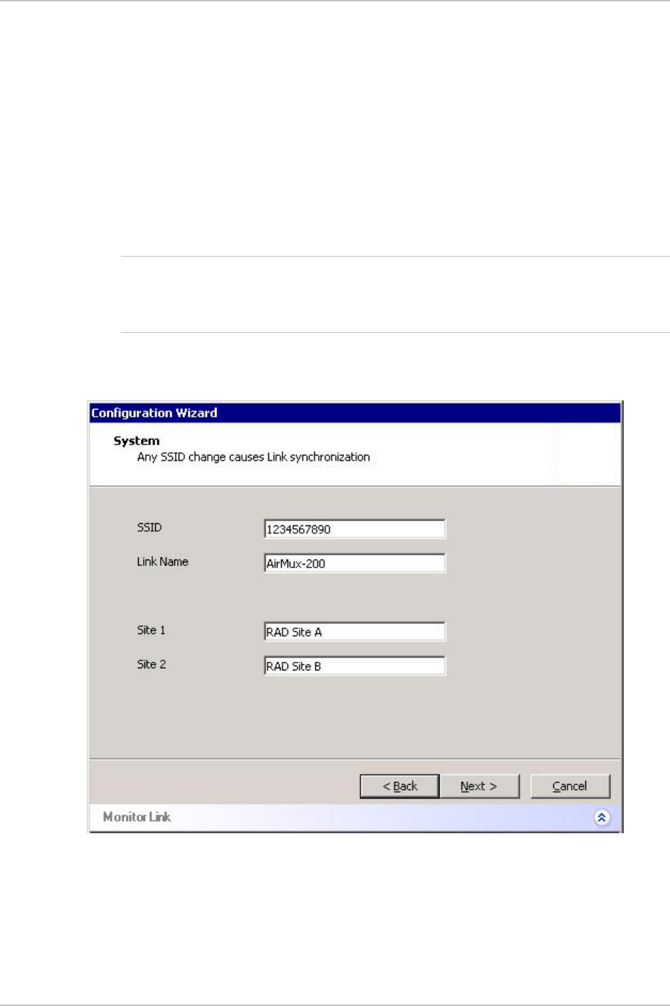
4. The General Parameters dialog box appears (see Figure 3-2).
Figure 3-2. General Parameters Dialog Box
5. From the General Parameters dialog box, enter data to describe the
link:
Note

Chapter 3 Configuration AirMux-200 Installation and Operation Manual
3-4 Performing Configuration of AirMux-200
§ SSID – System ID. This number is initially factory set. It can be
user defined, but both local and remote sites must have the
same number.
§ Link name – enter a name for the link identification.
§ Site 1 – enter location name of site 1
§ Site 2 – enter location name of site 2
6. Click Next.
The Channel Select dialog box appears (see Figure 3-3)
7. Select the required operating channel.
Table 3-1 lists channels and frequencies for ISM and UNII bands.
Figure 3-3. Channel select Dialog Box
Table 3-1. AirMux-200 Channels and Frequencies
Channel ISM Band UNII Band
1 5740 MHz 5740 MHz
2 5760 MHz 5760 MHz
3 5780 MHz 5780 MHz
4 5800 MHz 5800 MHz
AirMux-200 Installation and Operation Manual Chapter 3 Configuration
Performing Configuration of AirMux-200 3-5
5 5820 MHz –
6 5840 MHz –
Manual User defined channel, within frequency band
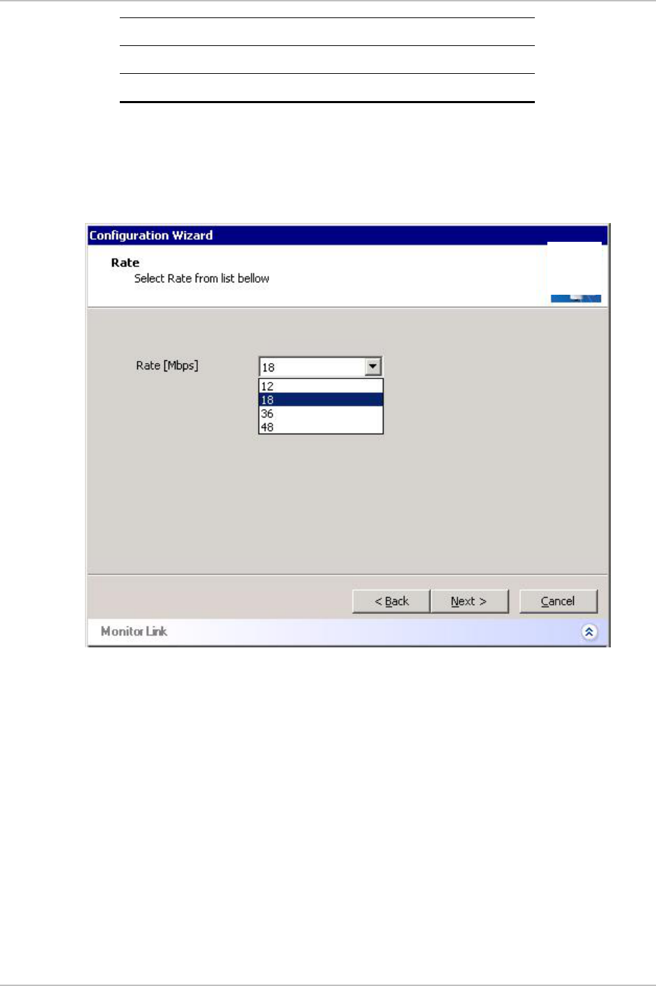
8. Click Next.
The Rate Select dialog box appears (see Figure 3-4)
Table 1-1 lists throughput rates and capacities.
Figure 3-4. Rate select Dialog Box
9. Click Next.
The Service Parameters dialog box appears (see Figure 3-5 and
Figure 3-6).
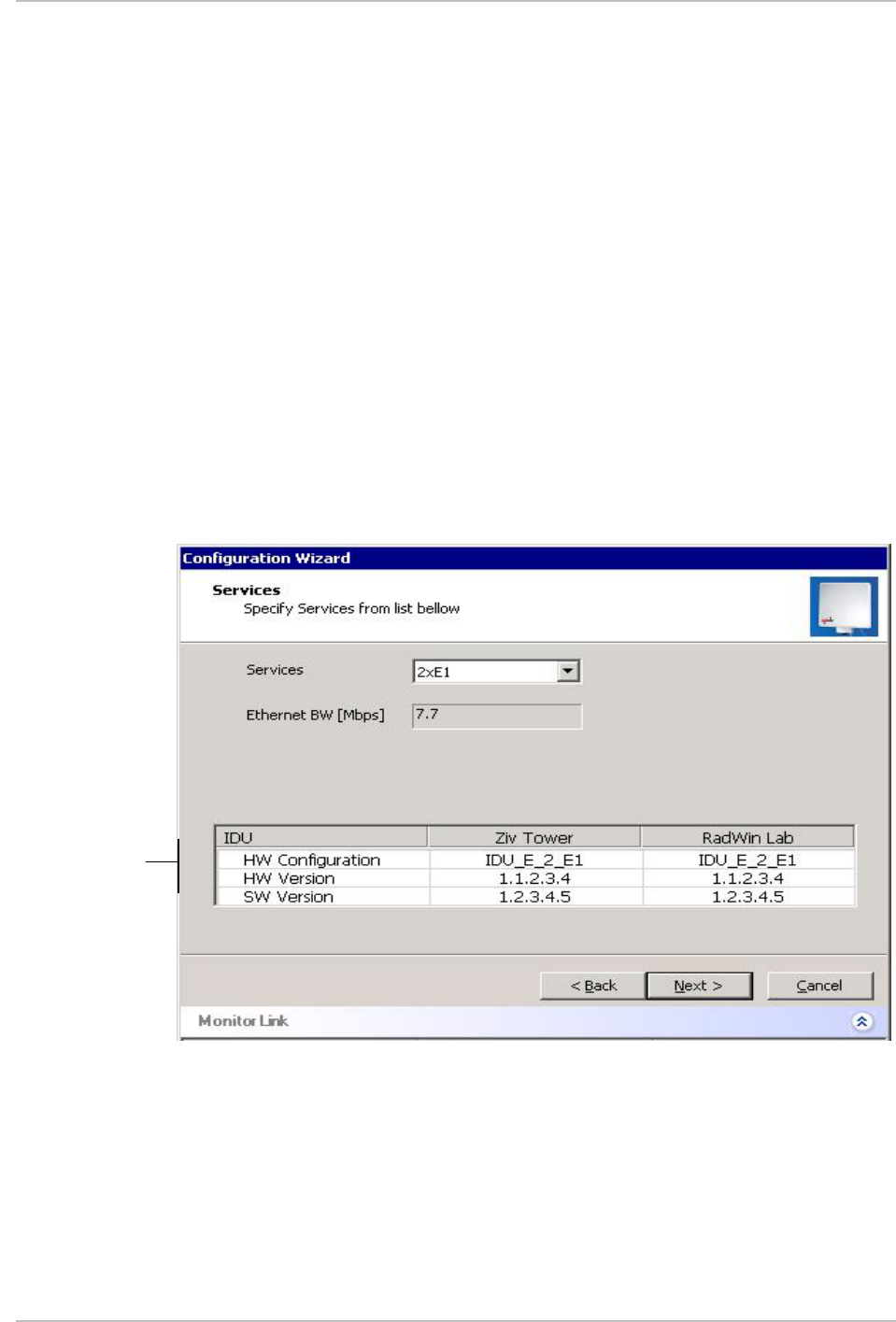
Configuring Service Parameters
In the Service Parameters dialog box configure E1/T1 (x1 or x2) and
Ethernet parameters.
ä To configure E1/T1 and Ethernet:
1. In the Service dialog box, select one of the following:
Chapter 3 Configuration AirMux-200 Installation and Operation Manual
3-6 Performing Configuration of AirMux-200
§ E1/T1 – Select the E1/T1 field, if you intend to transmit E1/T1
data and Ethernet data (see Figure 3-5).
The Ethernet BW field shows the remaining bandwidth in Mbps
available for Ethernet. The available bandwidth depends on the
number of E1/T1 ports selected.
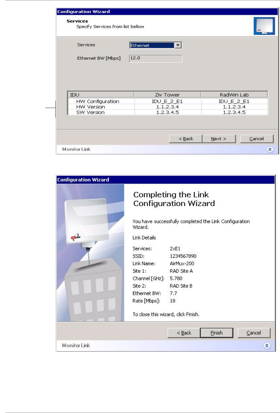
§ Select the Ethernet field, if you intend to transmit Ethernet data
only
(see Figure 3-6)
2. Click Next.
The Finish screen appears (see Figure 3-7).
The Finish screen shows a summary of the link configuration.
3. Click Finish to complete the configuration wizard.
Figure 3-5. Service Parameters Dialog Box, E1 Interface
Inventory
AirMux-200 Installation and Operation Manual Chapter 3 Configuration
Performing Configuration of AirMux-200 3-7
Figure 3-6. Service Parameters Dialog Box, Ethernet only Interface
Figure 3-7. Configuration Wizard Finish Screen
Inventory
Front Panel Indicators 4-1
Chapter 4
Operation
This chapter provides the following information for AirMux-200:
• AirMux-200 front panel indicators
• Operating procedures (turn-on, front panel indications,
performance monitoring and turn-off)
• Procedures for changing AirMux-200 configuration parameters.
4.1 Front Panel Indicators
The front panel of AirMux-200 includes a series of LED indicators that
show the current operating status of the unit.
Figure 4-1 shows the front panel of the AirMux-200 unit. Table 4-1
describes the AirMux-IDU indicators.
AirMux-IDU
SERVICE
AIR I/F
RTCB
RT
PWR
Figure 4-1. Front Panel
Table 4-1. IDU LEDs
Name Function Location
SERVICE
(green/red) ON (green) – E1 or T1 line is synchronized
ON (red) – Alarm is detected at the E1 or T1 interface
Front panel
AIR I/F (red) ON (green) – Wireless link is synchronized
ON (red) – Wireless link lost synchronization
Front panel
RTCB (green) ON – IDU self-test was completed successfully Front panel
RT
(green/red) ON (green) – ODU-to-IDU communication link is operating
properly
ON (red) – ODU-to-IDU communication link is disrupted
Front panel
PWR (green) ON – A power supply is ON Front panel

Chapter 4 Operation AirMux-200 Installation and Operation Manual
4-2 Operating AirMux-200
LINK (green) ON – Good Ethernet link integrity Rear panel LAN
connector
ACT (yellow) Blinks according to the Ethernet traffic Rear panel LAN
connector
4.2 Operating AirMux-200
Turning On AirMux-200
ä To turn on AirMux-200:
• Connect the AC/DC converter to the IDU power connector and to
the mains.
The PWR indicator lights up and remains lit as long as the IDU is
receiving power.
AirMux-200 requires no operator attention once installed, with the
exception of occasional monitoring of front panel indicators and
statistics data. Intervention is only required when AirMux-200 must be
configured to its operational requirements, or diagnostic tests are
performed.
Normal Indications
Upon turning on AirMux-200, the PWR LED in the IDU front panel lights
to indicate that AirMux-200 is on. Table 4-2 shows the correct status
of the indicators a few seconds after power-up.
Table 4-2. AirMux-200 Indicator Status
Indicator Status
PWR ON
RTCB Green – Blinking
slowly
RT Green – Blinking
slowly
Air Green – Blinking
slowly
Service Green – Blinking
slowly

AirMux-200 Installation and Operation Manual Chapter 4 Operation
Operating AirMux-200 4-3
If the above LED indications do not appear following initial power turn-
on, refer to Chapter 5 for the diagnostic test instructions.
During normal operation, the PWR led stays ON, all other LEDs blink at
a four second cycle.
Turning Off AirMux-200
ä To turn off AirMux-200:
• Remove the AC/DC converter power cord from the mains.
Note
Chapter 4 Operation AirMux-200 Installation and Operation Manual
4-4 Managing AirMux-200
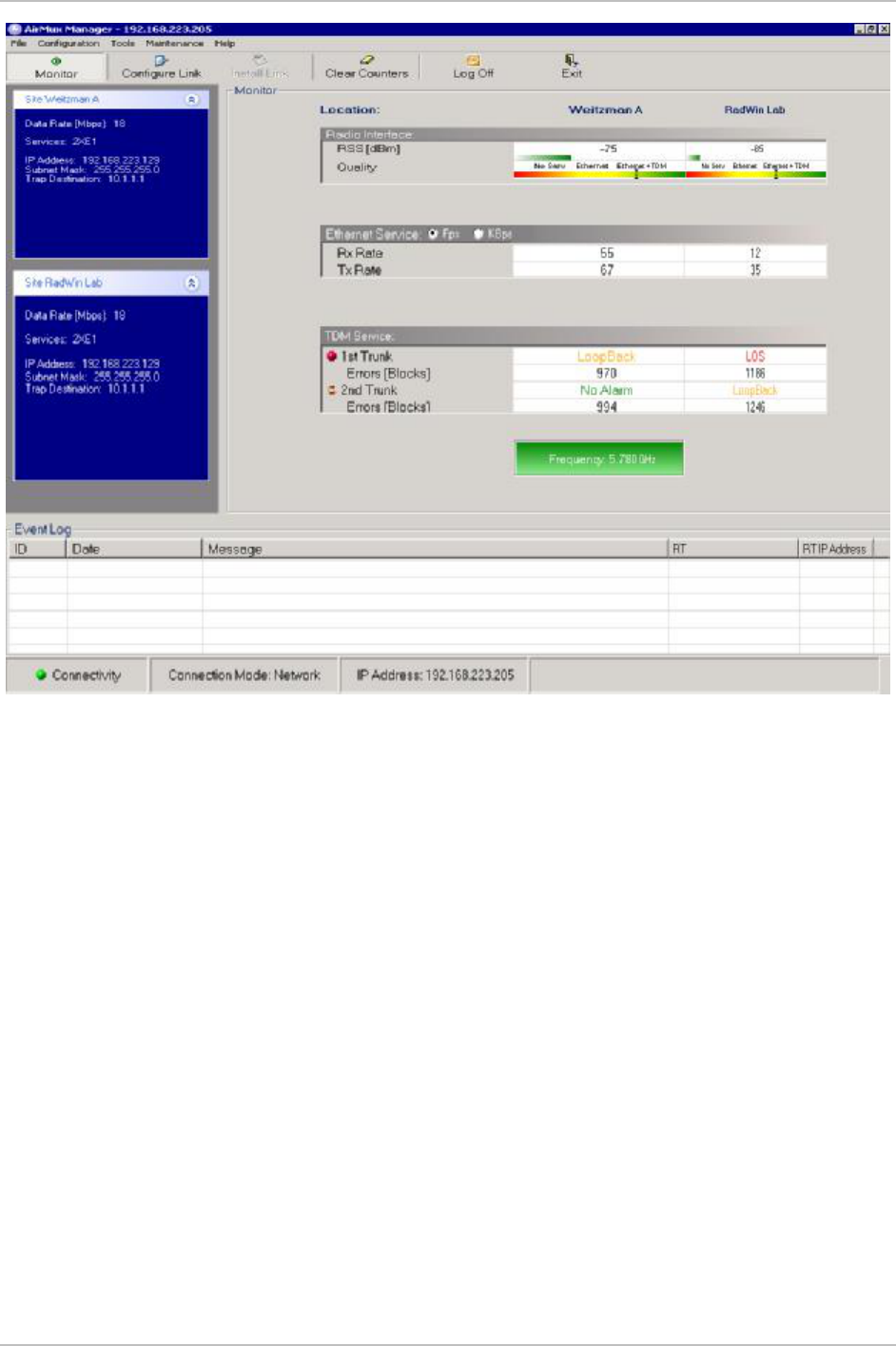
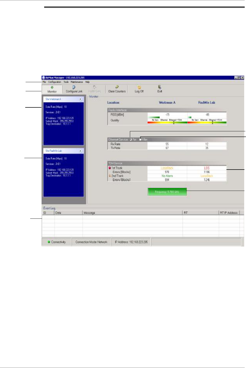
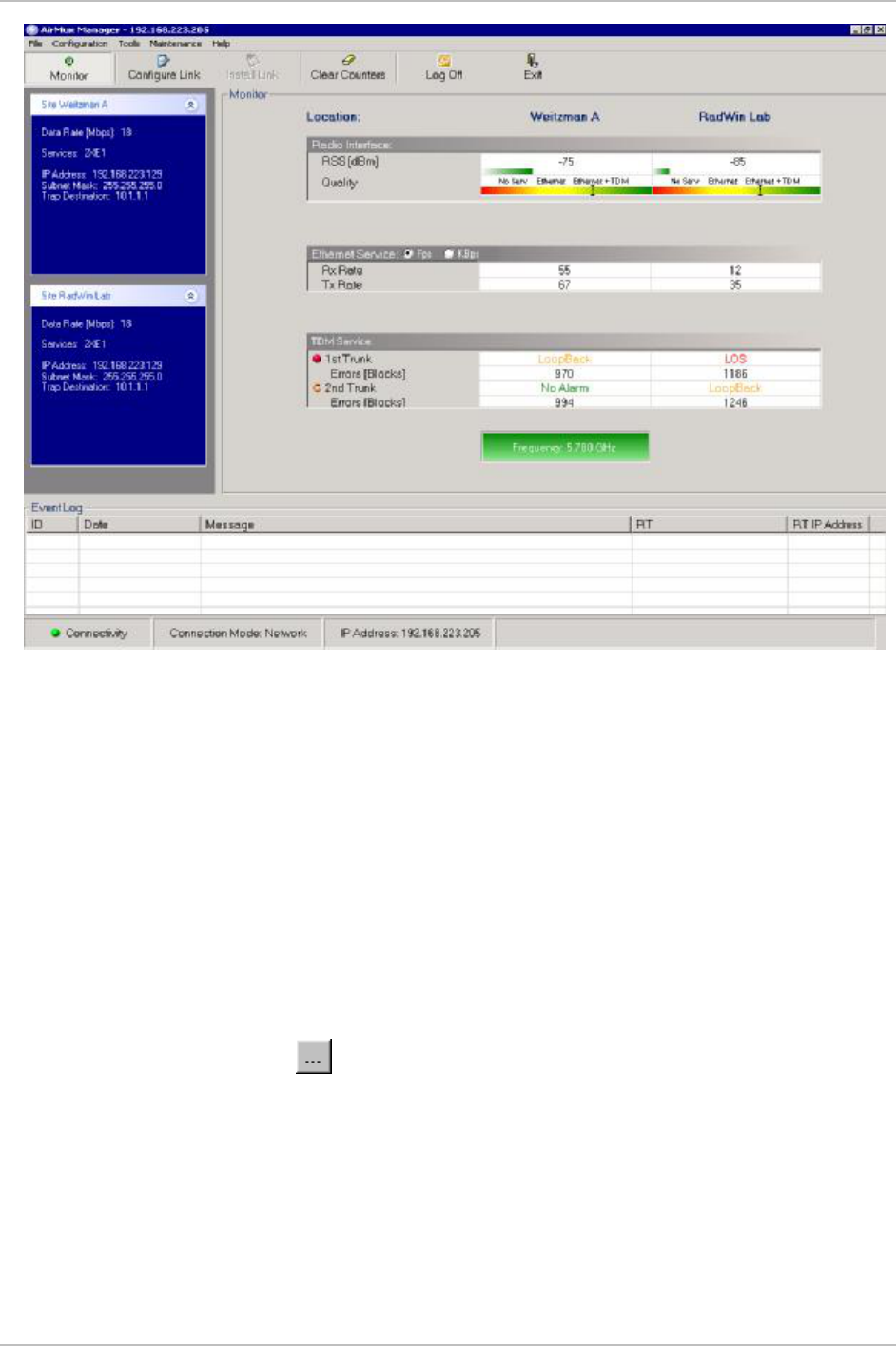
4.3 Managing AirMux-200
Before starting a management session, make sure that a
communication link between local and remote units exists. The Link
Status indication bar in the middle of the Main menu must be green,
the Radio Link - Sync message appears in the event log (see Figure 4-
2).
Figure 4-2. Main Menu, Wireless Link is Active
The AirMux Manager Main menu consists of the following elements:
• Toolbar – includes buttons serving for:
§ Monitoring wireless (radio) link (Monitor button)
§ Changing configuration parameters of operating wireless link,
assigning text files for storing alarms, statistics and
configuration data (Configure Link button)
§ Performing preliminary configuration of the system (Install Link
button). This button is disabled once a link is defined.
§ Clearing error counters (Clear Counters button)
Menu Bar
Toolbar
Site A
details
Site B
details
Event Log
Link Quality
Fram
es
Link
TDM Service
details
Traffic Rate

AirMux-200 Installation and Operation Manual Chapter 4 Operation
Managing AirMux-200 4-5
§ Logging off AirMux Manager (Log Off button)
§ Exiting AirMux Manager (Exit button)
• Menu bar – functions are similar to those of the toolbar.
• Link Parameters – summarizes information on the radio frequency,
IP bandwidth, type of TDM service, number of assigned E1 or T1
timeslots, and IP details of the local and remote AirMux-200 units.
• Local and Remote Statistics – monitor traffic between local and
remote devices and collect following statistics:
§ Local/remote received traffic rate (in kbps)
§ Local/remote received frames rate (in fps)
§ Radio link status
§ E1 or T1 link status
§ Radio signal strength (RSS) in dBm
§ Signal-to-noise ratio (SNR) in dB
§ Bit error rate.
• Event log – stores alarms generated by local and remote units.
ä To change link configuration parameters:
1. In the Main menu, click Configure Link.
The Configure Link wizard appears (see Figure 4-3). See Chapter
3 for configuration details.
2. Click Next.
3. In the General Parameters dialog box enter a new link name,
locations of the local and remote ODUs.
4. Click Next.
5. Continue through the configuration wizard and define the Channel,
Rate and Services of the link.
6. Once you finish changing configuration parameters, click Finish.
Both AirMux-200 units are reset automatically (initially the
remote unit, then the local one).
Chapter 4 Operation AirMux-200 Installation and Operation Manual
4-6 Managing AirMux-200
Figure 4-3. Configure Link Dialog Box
Resetting AirMux-200
In order to maintain the communication link, always reset remote
AirMux-200 first.
ä To reset AirMux-200:
1. Click on maintenance select a local or remote AirMux-200 to reset.
Saving AirMux-200 Configuration in a File
AirMux-200 management software allows you to save configuration
parameters of the local and remote units on the management station
as an INI file.
ä To save configuration in a file:
1. From the Configuration menu (see Figure 4-3), click Backup.
2. In the Save As dialog box, indicate in which folder and under what
name configuration file is to be saved, and click Save.
Note

AirMux-200 Installation and Operation Manual Chapter 4 Operation
Managing AirMux-200 4-7
Uploading Configuration File
Configuration files (*.ini) can be uploaded from the management
station, if the AirMux-200 database becomes corrupted. This can also
be used to distribute verified configuration files to all other units that
use the similar configuration.
ä To upload configuration file to AirMux-200:
1. From the Configuration menu, select Configure Local ODU.
The Configure Local ODU menu appears
2. From the Configure Local ODU menu, click Restore.
3. From the Open dialog, select *.ini file to upload and click OK.
4. From the Select ODU by Location menu, select the ODU to which the
configuration file will be downloaded (local or remote).
AirMux Manager displays confirmation message asking your
approval to perform the download and restart the ODU.
5. Click Yes to approve.
The configuration file is downloaded to the ODU and devices are
reset.
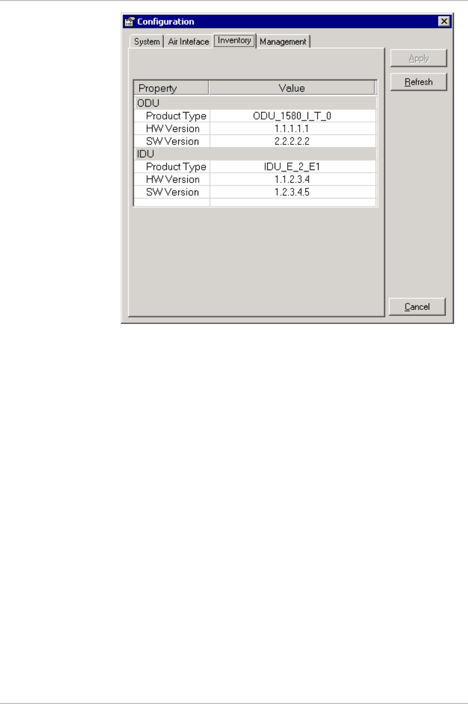
Displaying the AirMux-200 Inventory
The AirMux-200 inventory includes information on the hardware,
firmware and software versions of the local and remote units.
ä To display inventory:
• In the Configuration dialog box, click the Inventory tab.
The local and remote inventory information is displayed (see
Figure 4-4).
Chapter 4 Operation AirMux-200 Installation and Operation Manual
4-8 Managing AirMux-200
Figure 4-4. AirMux-200 Inventory

Error Detection 5-1
Chapter 5
Diagnostics and
Troubleshooting
This chapter describes the AirMux-200 diagnostic functions, which
include:
• Status indications, alarms, power-up self-test
• Statistics collection
• Diagnostic tests (local and remote loopbacks on E1 or T1 link).
5.1 Error Detection
Power-Up Self-Test
AirMux-200 performs a hardware test of the IDU upon turn-on. This
self-test checks the critical circuit functions of the unit. The RTCB LED
indicates results of the self-test (see Chapter 4 for LED descriptions).
Alarms
AirMux-200 detects fault conditions of the radio and user links and
initiates alarms to alert the user. The user can save the alarm log as a
TXT file.
Alarms are displayed in the Event Log (see Figure 5-1).
The event log includes the following fields:
• Alarm sequential number
• Date and time stamp
• Message
• Alarm source (local or remote ODU)
• IP address of the ODU that initiated alarm.

Chapter 5 Diagnostics and Troubleshooting AirMux-200 Installation and Operation Manual
5-2 Error Detection
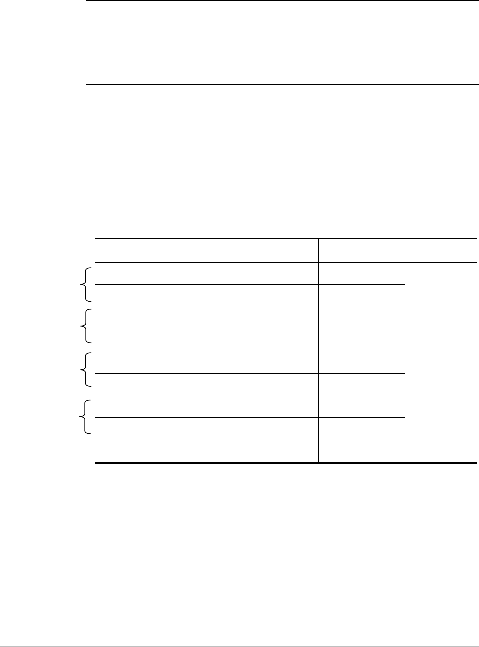
Table 5-1. AirMux-200 Alarms and Information Messages
Message Description
Radio Link – Sync Radio link is synchronized
Radio Link – Out Of Sync Radio link lost synchronization
Link Has Been Reset ODU was reset due to internal problem
TDM Interface – Normal TDM interface is operating properly
TDM Interface – LOS Loss of Synchronization is reported by TDM interface
Table 5-1. AirMux-200 Alarms and Information Messages (Cont.)
Message Description
TDM Interface – LOF Loss of Frame alignment is reported by TDM interface
TDM Interface – AIS Alarm Indication Signal is reported by TDM interface
TDM Interface – RAI Remote Alarm Indication is reported by TDM interface
TDM Interface – CRC CRC error was detected at TDM interface
TDM Interface – CRC_E_BIT CRC E-Bit error was detected at TDM interface
TDM Interface – Loopback A loopback is active on TDM interface
Failed to download data to the
remote ODU AirMux-200 failed to download configuration data to the
remote ODU
Failed to download data to the
local ODU AirMux-200 failed to download configuration data to the
local ODU
Link Resetting Wireless link reset from the management station. This
alarm is caused by automatic reset after link
configuration.
Local ODU Resetting The local ODU reset from the management station.
Error loading trap catcher AirMux Manager detected that the SNMP port 162 of the
management station has been previously captured by
another application and cannot receive traps.
Monitor was stopped since no
connection to the link No ODU-to-IDU traffic was detected during the last 20
minutes.
AirMux-200 Installation and Operation Manual Chapter 5 Diagnostics and Troubleshooting
Error Detection 5-3
Figure 5-1. AirMux-200 Alarms and Status Indications
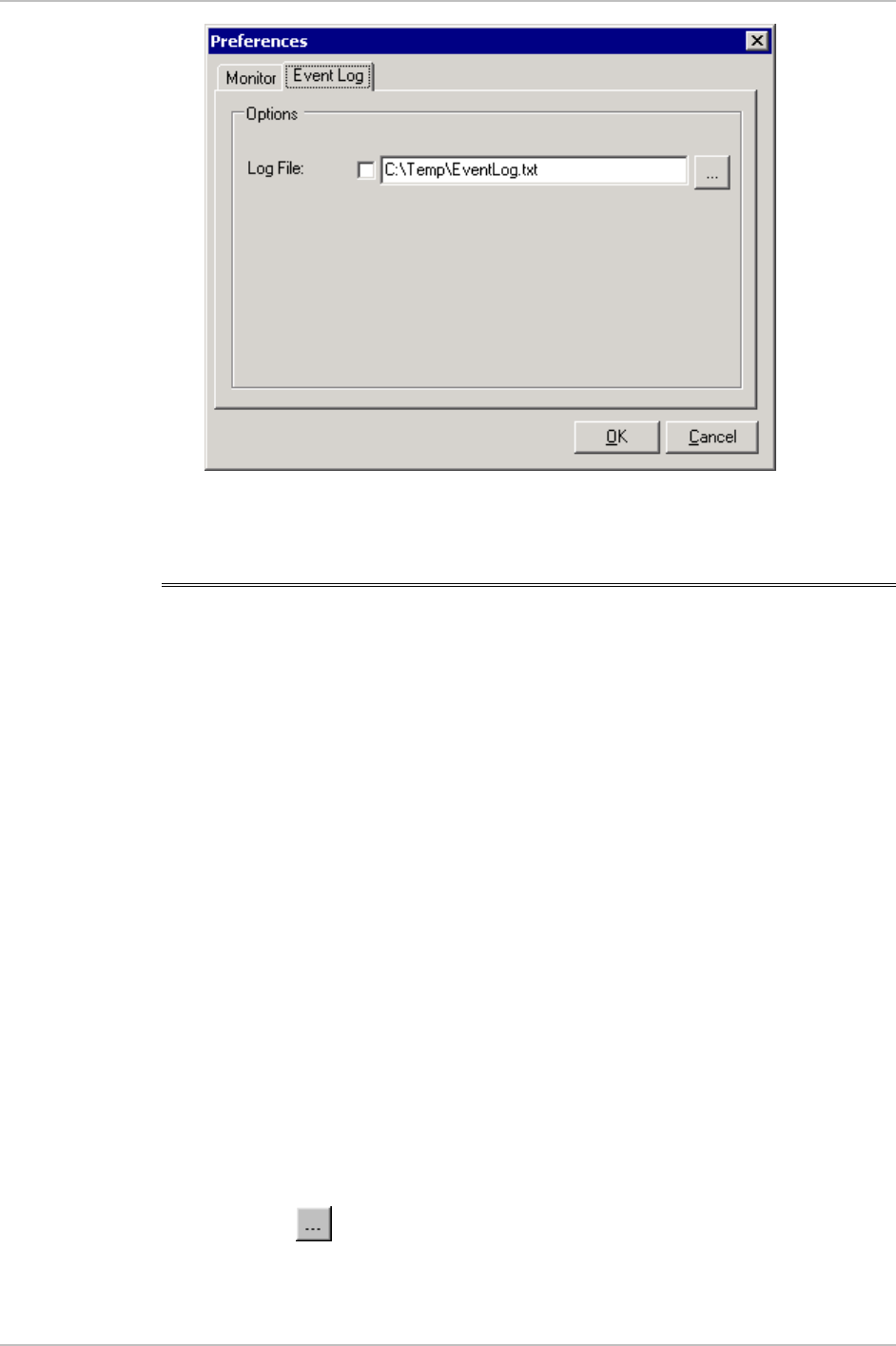
Saving Event Log
The event log can be saved as a TXT file. New alarms are automatically
added to the text file, as they enter the event log.
ä To save alarm log:
1. From the Tools menu, choose Preferences.
The Preferences dialog box appears.
2. From the Preferences dialog box, select Event Log tab (see Figure 5-
2).
3. Click the button and in the Select File dialog box indicate in
which folder and under what name the alarm log file is to be saved,
and click Save.
Chapter 5 Diagnostics and Troubleshooting AirMux-200 Installation and Operation Manual
5-4 Collecting Statistics
Figure 5-2. Preferences Dialog Box, Event Log Tab
5.2 Collecting Statistics
AirMux-200 constantly monitors traffic over the radio link and collects
the following statistics data:
• Local/remote received traffic rate (in kbps)
• Local/remote received frames rate (in fps)
• Radio signal strength (in dBm)
• Signal-to-noise ratio (in dB)
• Bit error rate.
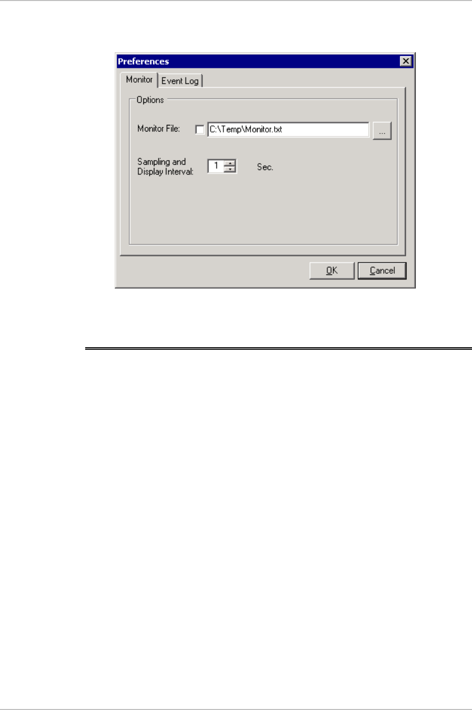
Statistics log can also be saved as a text file.
ä To save statistics log:
1. From the Tools menu, choose Preferences.
The Preferences dialog box appears.
2. From the Preferences dialog box, select Monitor tab (see Figure 5-
3).
3. Click the button and in the Select File dialog box indicate in
which folder and under what name the statistics log file is to be
saved, and click Save.
AirMux-200 Installation and Operation Manual Chapter 5 Diagnostics and Troubleshooting
Running Diagnostic Loopbacks 5-5
4. In the Interval box, type or select statistics refresh interval (in
seconds).
Figure 5-3. Preferences Dialog Box, Monitor Tab
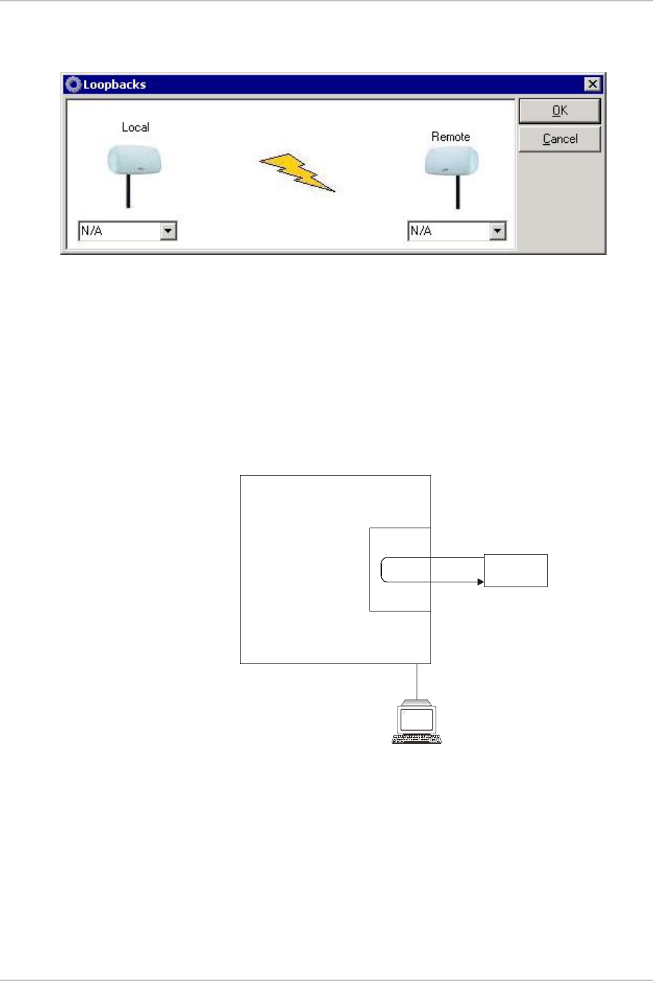
5.3 Running Diagnostic Loopbacks
AirMux-200 supports activation of the internal and external loopbacks
on the local and remote units.
ä To activate a loopback:
1. From the Maintenance menu, choose Set Loopbacks.
The Loopbacks dialog box appears (see Figure 5-4).
2. From the Local or Remote drop-down box, select a loopback that
you intend to run, and click OK.
A confirmation message appears.
3. Click Yes to activate a loopback.
AirMux-200 activates selected loopback. A loopback status
arrow in the Main menu turns green to indicate an active
loopback.
ä To deactivate a loopback:
• From the From the Local or Remote drop-down box of the
Loopbacks dialog box, select N/A and confirm your choice.
Chapter 5 Diagnostics and Troubleshooting AirMux-200 Installation and Operation Manual
5-6 Running Diagnostic Loopbacks
A loopback is deactivated and the corresponding status arrow in
the Main menu becomes dimmed.
Figure 5-4. Loopbacks Dialog Box
Local External Loopback
Local AirMux-200 can be set to an external loopback to test the local
E1/T1 port and its connection to the local side user equipment. In this
mode, data coming from the local user equipment is looped back to it
(see Figure 5-5). This loopback is initiated from a management station
connected to the local unit.
Testing
Equipment
Management
Station
E1/T1
Interface
Local RT
Figure 5-5. Local External Loopback
Remote Internal Loopback
Remote AirMux-200 can be set to an internal loopback to test
connection between the local and remote units, the local E1/T1 port
and its connection to the local side user equipment. In this mode, data
coming from the local AirMux-200 is looped back to it (see Figure 5-
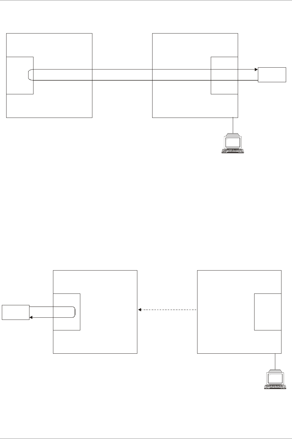
AirMux-200 Installation and Operation Manual Chapter 5 Diagnostics and Troubleshooting
Running Diagnostic Loopbacks 5-7
6). This loopback is initiated from a management station connected to
the local unit.
Management
Station
E1/T1
Interface E1/T1
Interface
Testing
Equipment
Remote RT
Local RT
Figure 5-6. Remote Internal Loopback
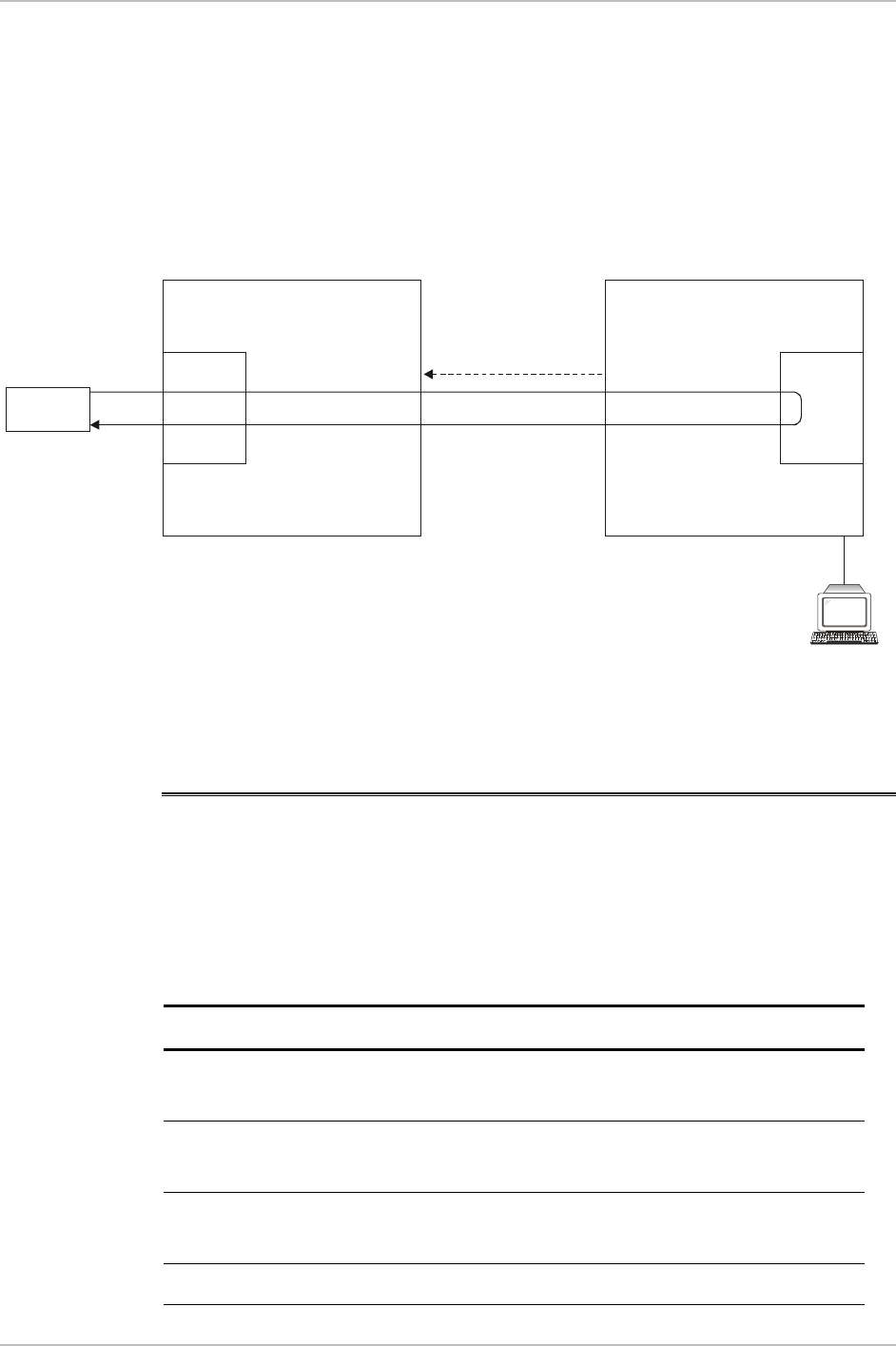
Remote External Loopback
Remote AirMux-200 can be set to an external loopback to test the
remote E1/T1 port and its connection to the remote side user
equipment. In this mode, data coming from the remote user equipment
is looped back to it (see Figure 5-7). This loopback is initiated by an
inband command sent from a management station connected to the
local unit.
Testing
Equipment
Management
Station
E1/T1
Interface E1/T1
Interface
Local RT
Inband Loopback
Activation Command
Remote RT
Figure 5-7. Remote External Loopback
Chapter 5 Diagnostics and Troubleshooting AirMux-200 Installation and Operation Manual
5-8 Troubleshooting
Local Internal Loopback
Local AirMux-200 can be set to close an internal loopback to test
connection between the local and remote units, remote E1/T1 port and
its connection to the remote side user equipment. In this mode, data
coming from the remote user equipment is looped back to it (see
Figure 5-8). This loopback is initiated by an inband command sent
from a management station connected to the local unit.
Testing
Equipment
Management
Station
E1/T1
Interface E1/T1
Interface
Local RT
Inband Loopback
Activation Command
Remote RT
Figure 5-8. Local Internal Loopback
5.4 Troubleshooting
The AirMux-200 LEDs show faults in the system or the link. Use Table
5-2 to diagnose the fault.
Table 5-2. Troubleshooting with AirMux-200 LEDs
LED status Action
PWR LED is off Check that AC adapter is connected to the IDU
and the AC power outlet
RTCB LED is yellow Check that the IDU/ODU cable is properly
wired and connected
RT LED is red Check that the IDU/ODU cable is properly
wired and connected
Air LED is yellow Complete the installation procedure from the

AirMux-200 Installation and Operation Manual Chapter 5 Diagnostics and Troubleshooting
Troubleshooting 5-9
management software
Air LED is RED Check the ODU Antenna alignment. Check that
the radio configuration of both local and
remote units are the same (channel and SSID)
Service LED is off Check the TDM service configuration in the
NMS
Service LED is yellow Check that the system is not in loopback
mode. Check the remote IDU ports and cables
and remote external equipment.
Service LED is red Check the local IDU ports, cables and external
equipment

Chapter 5 Diagnostics and Troubleshooting AirMux-200 Installation and Operation Manual
5-10 Troubleshooting
ODU-IDU Cable A-1
Appendix A
Wiring Specifications
A.1 ODU-IDU Cable
The ODU-IDU cable is standard CAT-5, 4 twisted-pair 24 AWG FTP.
The ODU-IDU cable is terminated in RJ-45 connectors on both ends. It
is covered by a cable gland on the ODU side for hermetic sealing.
Table A-1 shows the connector pinout.
Table A-1. ODU-IDU Cable Connector Pinout
IDU RJ45 Wire Color ODU RJ45 Function
1 White/Green 1 Twisted
2 Green 2
3 White/Orange 3 Twisted
6 Orange 6
Ethernet
4 Blue 4
Twisted 5 White\Blue 5
7 White/Brown 7
8 Brown 8
Twisted
Power

Appendix A Wiring Specifications AirMux-200 Installation and Operation Manual
A-2 User Port Connectors
A.2 User Port Connectors
The IDU includes ports for connecting E1/T1 and Fast Ethernet user
devices.
E1/T1 Port
E1/T1 interface terminates in an 8-pin RJ-45 balanced connector,
wired in accordance to Table A-2.
Table A-2. E1/T1 Connector Pinout
Pin Function
4,5 Receive (input)
1,2 Transmit
(output)
Fast Ethernet Port
Fast Ethernet interface terminates in an 8-pin RJ-45 connector, wired
in accordance to Table A-3.
Table A-3. Fast Ethernet Connector Pinout
Pin Signal Function
1 TD (+) Transmit Data
(positive)
2 TD (-) Transmit Data
(negative)
3 RD (+) Receive Data
(positive)
6 RD (-) Receive Data
(negative)

Mounting the ODU B-1
Appendix B
Mast and Wall Installation
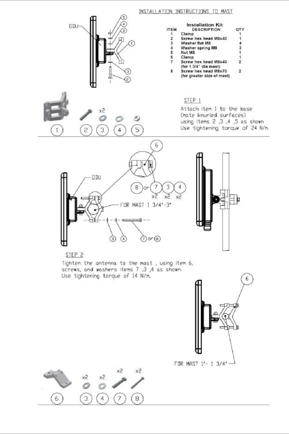
B.1 Mounting the ODU
The ODU can be mounted on masts and walls.
ODU Mounting Kit Contents
The ODU mounting kit includes the following items:
• One Large Clamp (see figure B-1)
• One Small Clamp (see figure B-2)
• One Arm (see figure B-3)
• Four Screw hex head M8x40
• Two Screw hex head M8x70
• Four Washer flat M8
• Three Washer spring M8
• Two M8 Nuts
Figure B-1. Large Clamp Figure B-2. Small Clamp

Appendix B Mast and Wall Installation AirMux-200 Installation and Operation Manual
B-2 Mounting the ODU
Figure B-3. Arm

AirMux-200 Installation and Operation Manual Appendix B Mast and Wall Installation
Mounting the ODU B-3
Mounting AirMux-200 on a Mast
Appendix B Mast and Wall Installation AirMux-200 Installation and Operation Manual
B-4 Mounting the ODU
AirMux-200 Installation and Operation Manual Appendix B Mast and Wall Installation
Mounting the ODU B-5
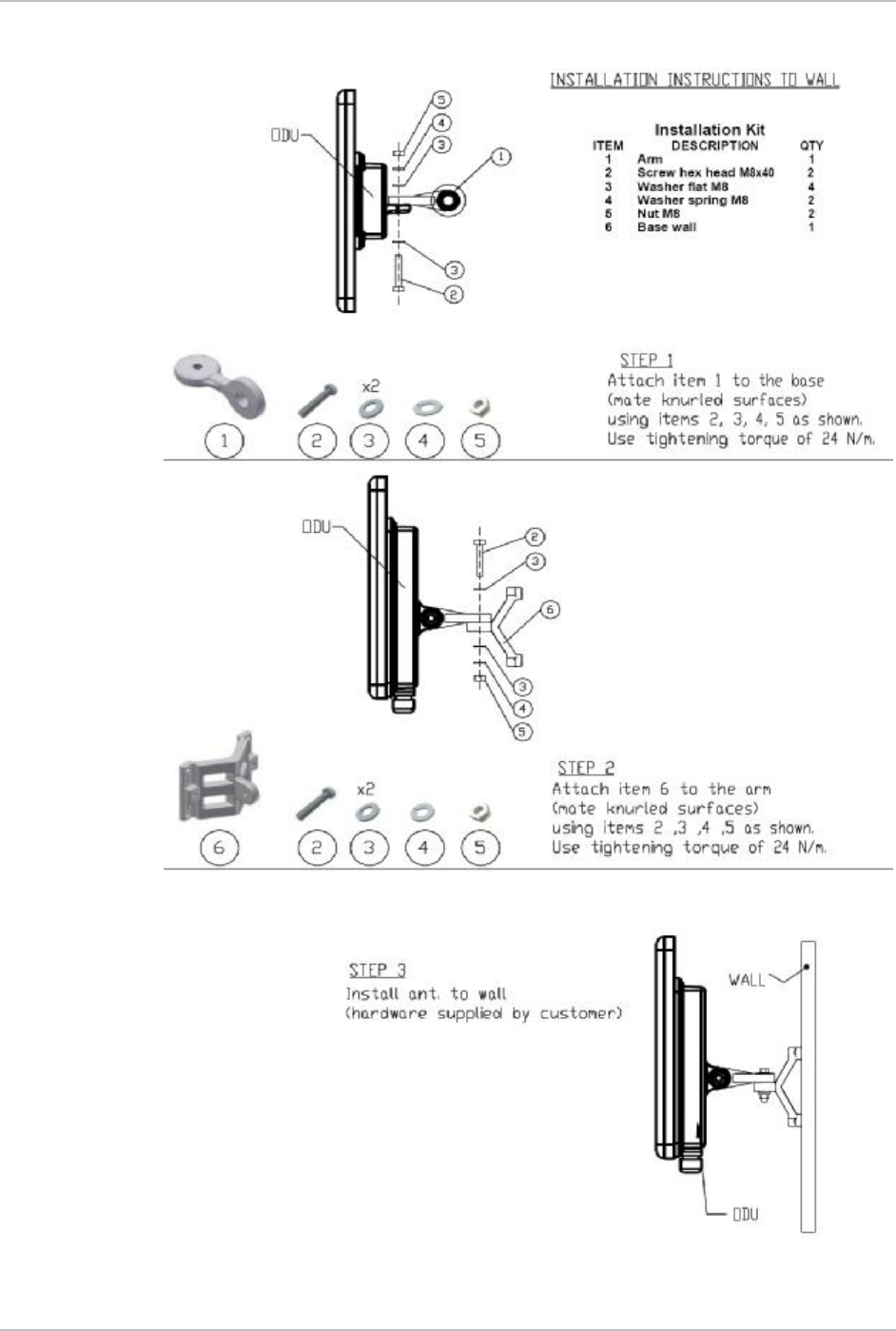
Mounting AirMux-200 on a Wall

Appendix B Mast and Wall Installation AirMux-200 Installation and Operation Manual
B-6 Mounting Optional External Antenna
B.2 Mounting Optional External Antenna
The optional external antenna can be mounted on masts.
External Antenna Mounting Kit Contents
The external antenna mounting kit includes the following items:
• Twelve flat washers
• Eight spring washers
• Eight hex nuts
• Four bolts
• One U-bracket
• One pivoting bracket
• Two metal strap clamps.
ä To install external antenna on the mast:
1. Attach the U-bracket to the back of the antenna using four flat
washers, four spring washers and four hex nuts.
2. Attach the pivoting bracket to the U-bracket using eight flat
washers, four spring washers, four hex nuts and four bolts.
3. Pass both strap clamps through the vertical slots in the pivoting
bracket.
4. Attach the antenna to the mast using the two strap clamps.
5. Adjust the required tilt using the angular scale and tighten all bolts
and nuts at the required position.

24 Raoul Wallenberg St., Tel Aviv 69719, Israel
Tel: +972-3-6458181, Fax: +972-3-6483331, +972-3-6498250
E-mail: , Web site:
Customer Response Form
RAD Data Communications would like your help in improving its product
documentation. Please complete and return this form by mail or by fax or send
us an e-mail with your comments.
Thank you for your assistance!
Manual Name: _____________________________________________________________
Publication Number: ________________________________________________________
Please grade the manual according to the following factors:
Excelle
nt Good Fair Poor Very
Poor
Installation instructions r r r r r
Operating instructions r r r r r
Manual organization r r r r r
Illustrations r r r r r
The manual as a whole r r r r r
What did you like about the manual?
___________________________________________________________________________
___________________________________________________________________________
erika_y@rad.co
www.rad.com
AirMux
-
200
xxx
-
200
-
05/04
___________________________________________________________________________
___________________________________________________________________________
___________________________________________________________________________
Error Report
Type of Error(s) r Incompatibility with product
or Problem(s): r Difficulty in understanding text
r Regulatory information (Safety, Compliance, Warnings, etc.)
r Difficulty in finding needed information
r Missing information
r Illogical flow of information
r Style (spelling, grammar, references, etc.)
r Appearance
r Other _________
Please list the exact page numbers with the error(s), detail the errors you found
(information missing, unclear or inadequately explained, etc.) and attach the page to
your fax, if necessary.
_________________________________________________________________________________________
_________________________________________________________________________________________
_________________________________________________________________________________________
_________________________________________________________________________________________
Please add any comments or suggestions you may have.
_________________________________________________________________________________________
_________________________________________________________________________________________
_________________________________________________________________________________________
You are: r Distributor
r End user
r VAR
r Other ________________________
Who is your distributor? _______________________________
Your name and company: _______________________________________________________
Job title: ________________________________________________________________________
Address: ________________________________________________________________________
Direct telephone number and extension: _________________________________________
Fax number: ____________________________________________________________________
E-mail: ___________________________________________________________________

900 Corporate Drive, Mahwah, N.J. 07430, Tel: (201) 529-1100
24 Raoul Wallenberg Street, Tel Aviv 69719, Israel, Tel: 972-3-6458181
U.S. HEADQUARTERS:
INTERNATIONAL HEADQUARTERS:
Publication No.
xxx
-
200
-
05/04
www.rad.com
Fax: 972-3-6498250, 972-3-6474436, Email: rad@rad.com
Toll Free: 1-800-444-7234, Fax: (201) 529-5777, Email: market@radusa.com