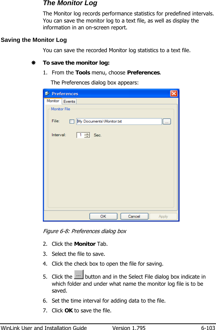
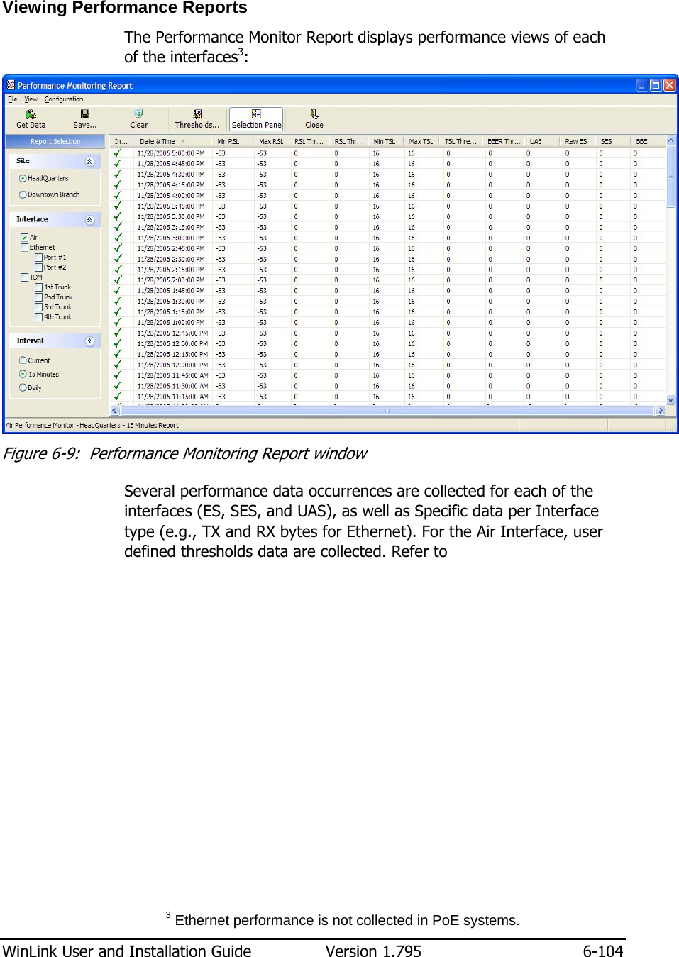
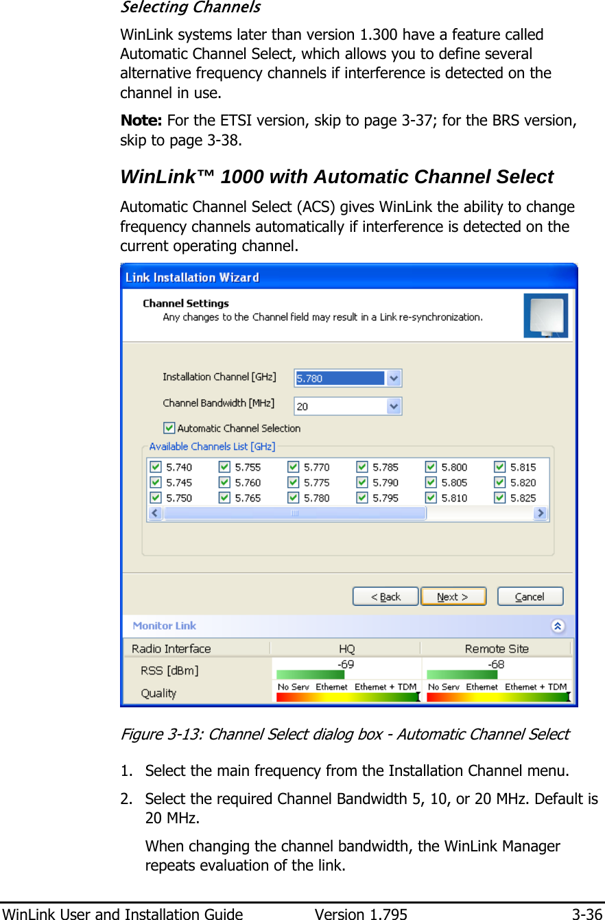
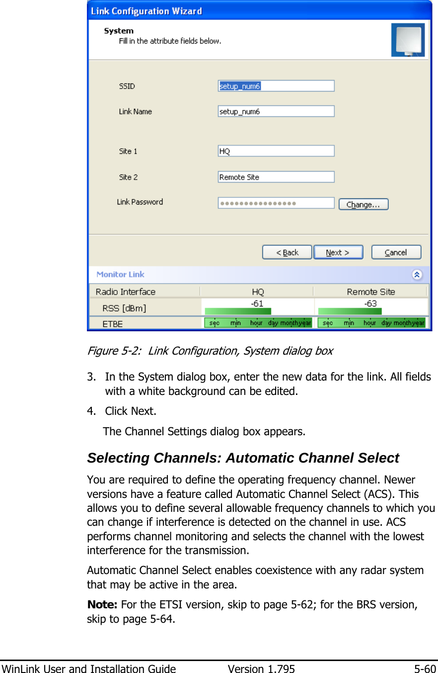
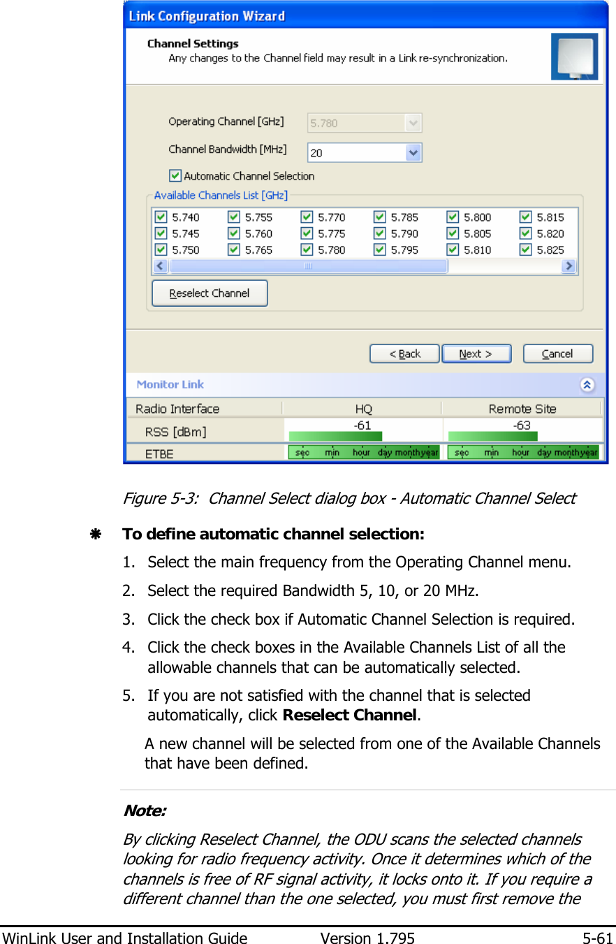
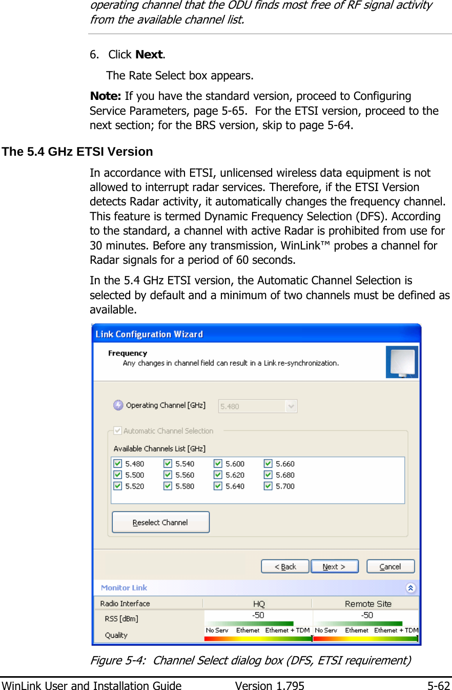
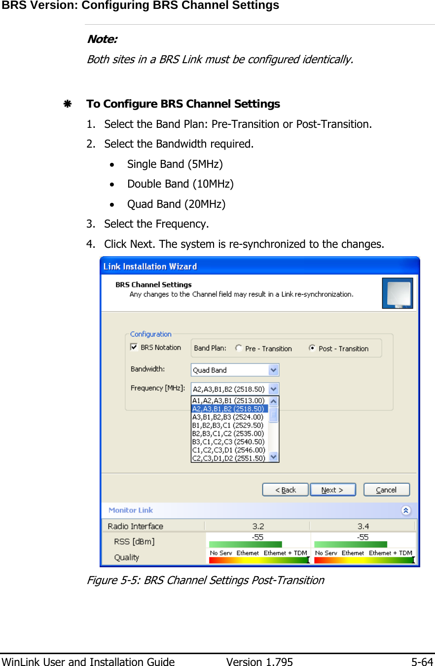
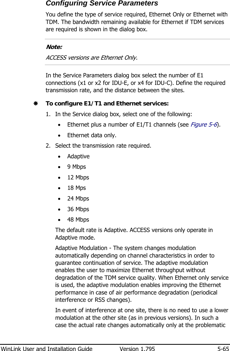
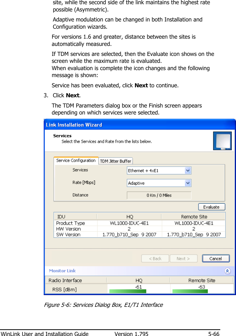
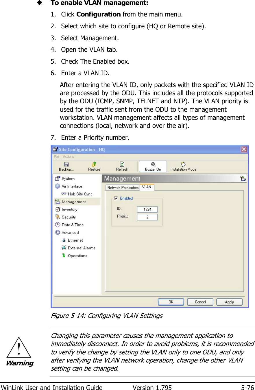
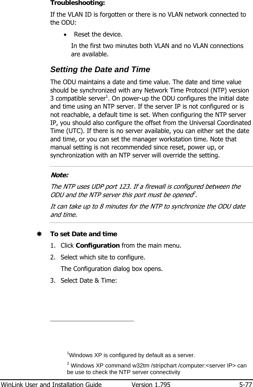
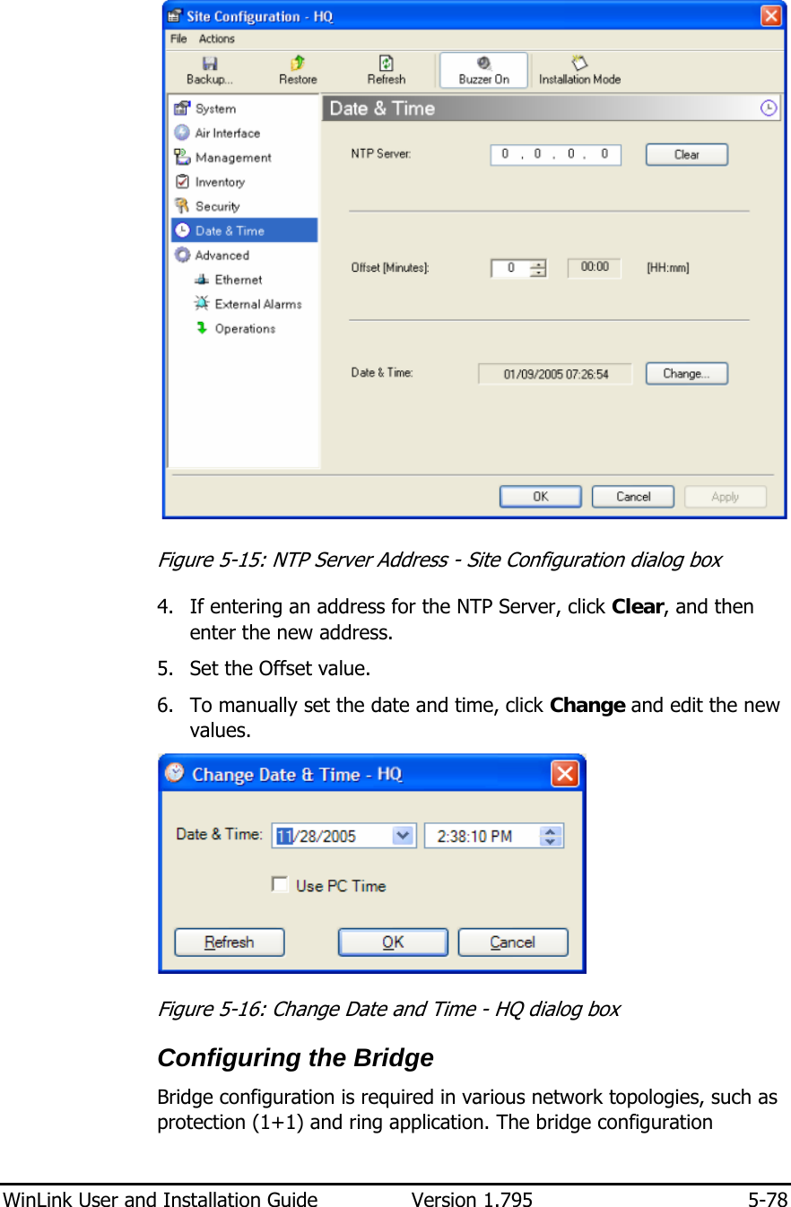
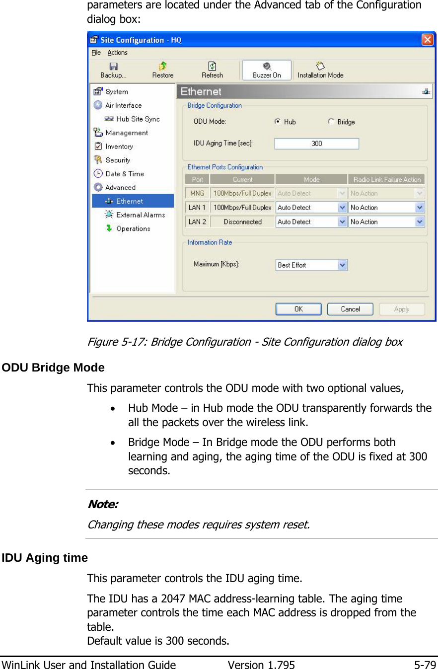
Radwin AMWL1540C Outdoor radio unit operating in 5.3 GHz and 5.4 GHz bands User Manual UM 1 795 1
Radwin Ltd. Outdoor radio unit operating in 5.3 GHz and 5.4 GHz bands UM 1 795 1
UserManual.wiki
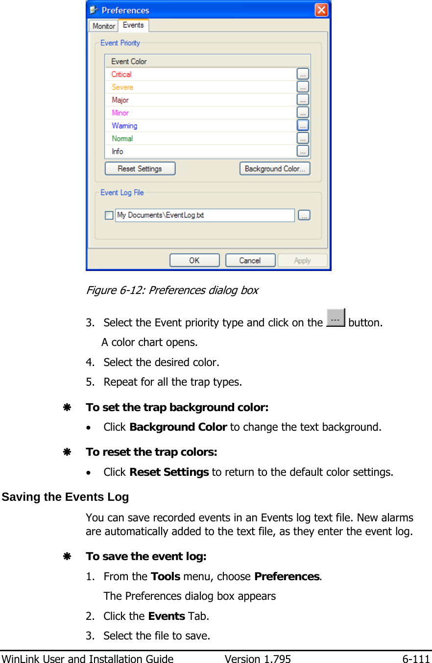
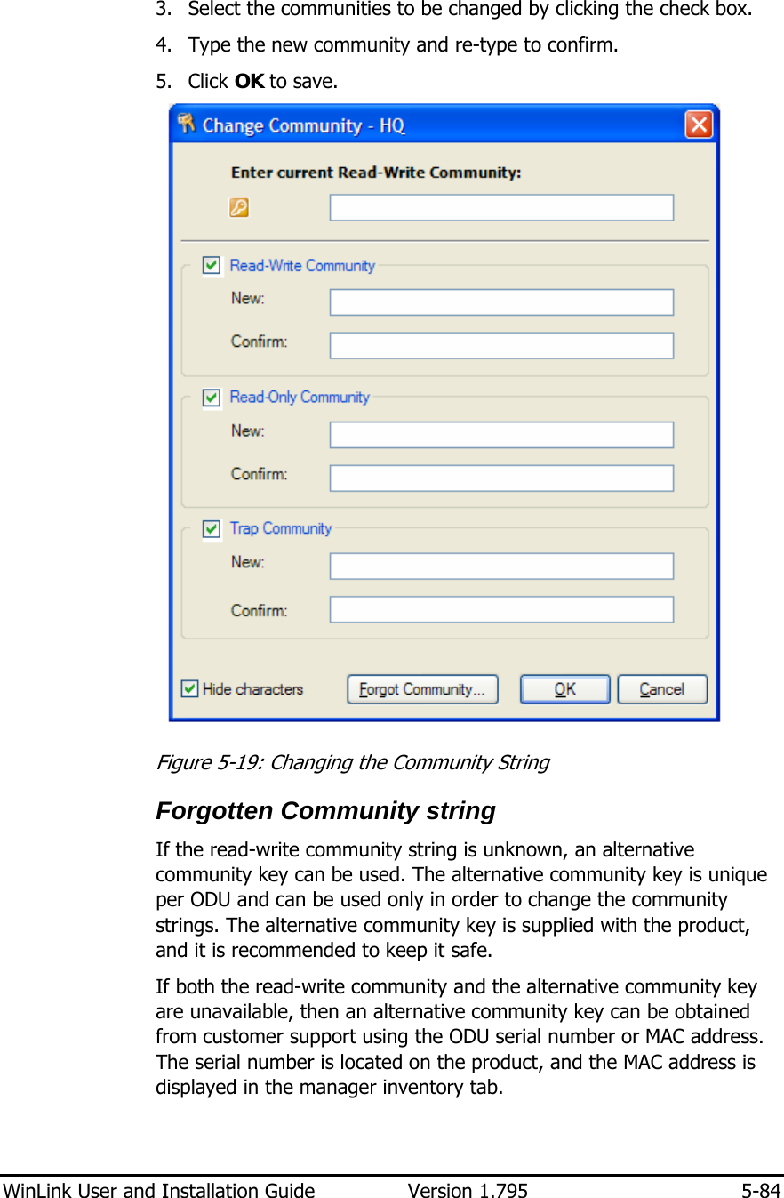
>
Radwin
>
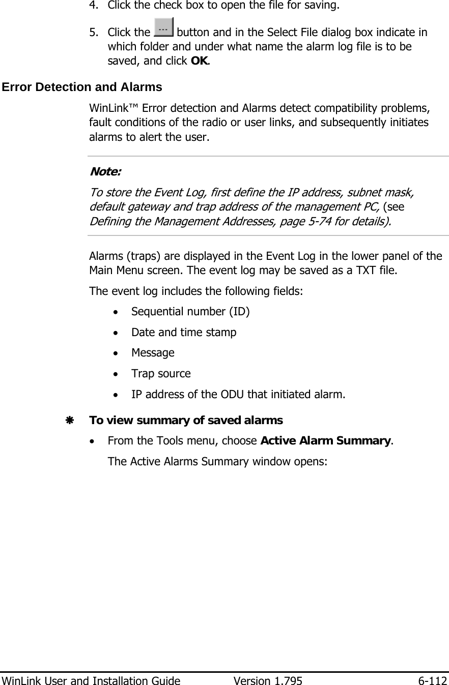
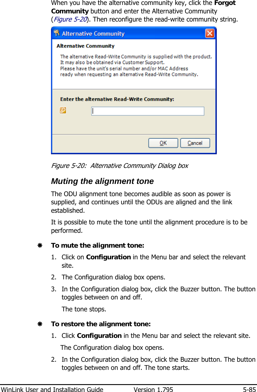
AMWL1540C User Manual
User manual
Navigation menu
Upload a User Manual
Namespaces
Wiki Guide
HTML
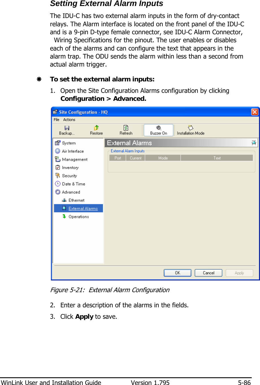
PDF
Info
Views
User Manual
Discussion / Help
Navigation
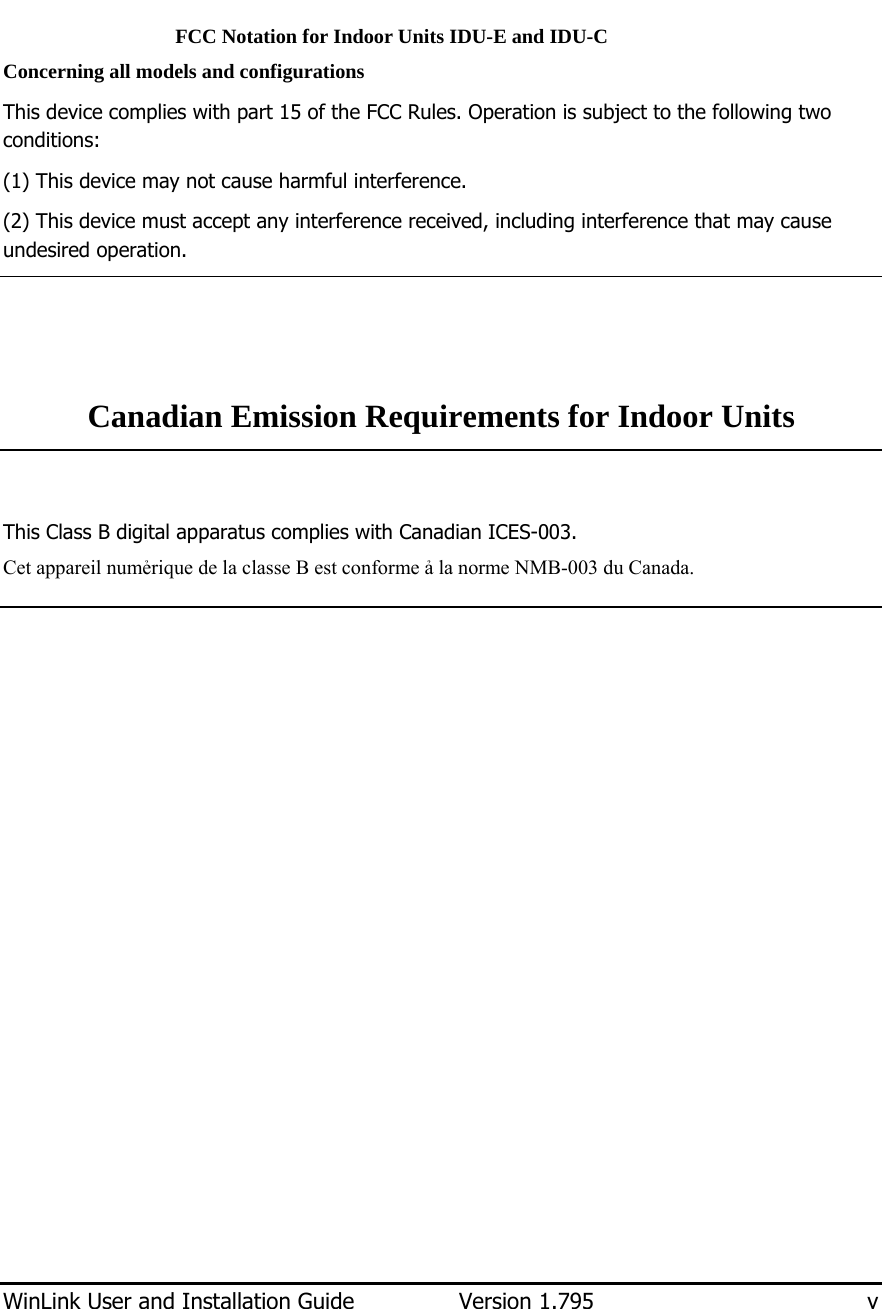
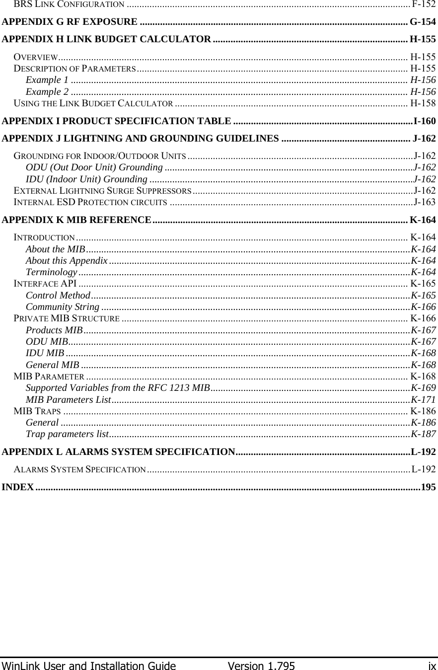
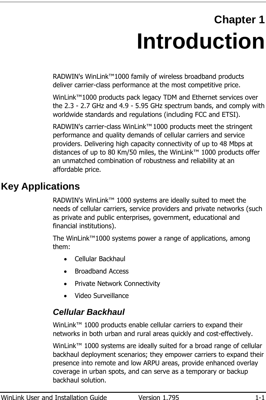
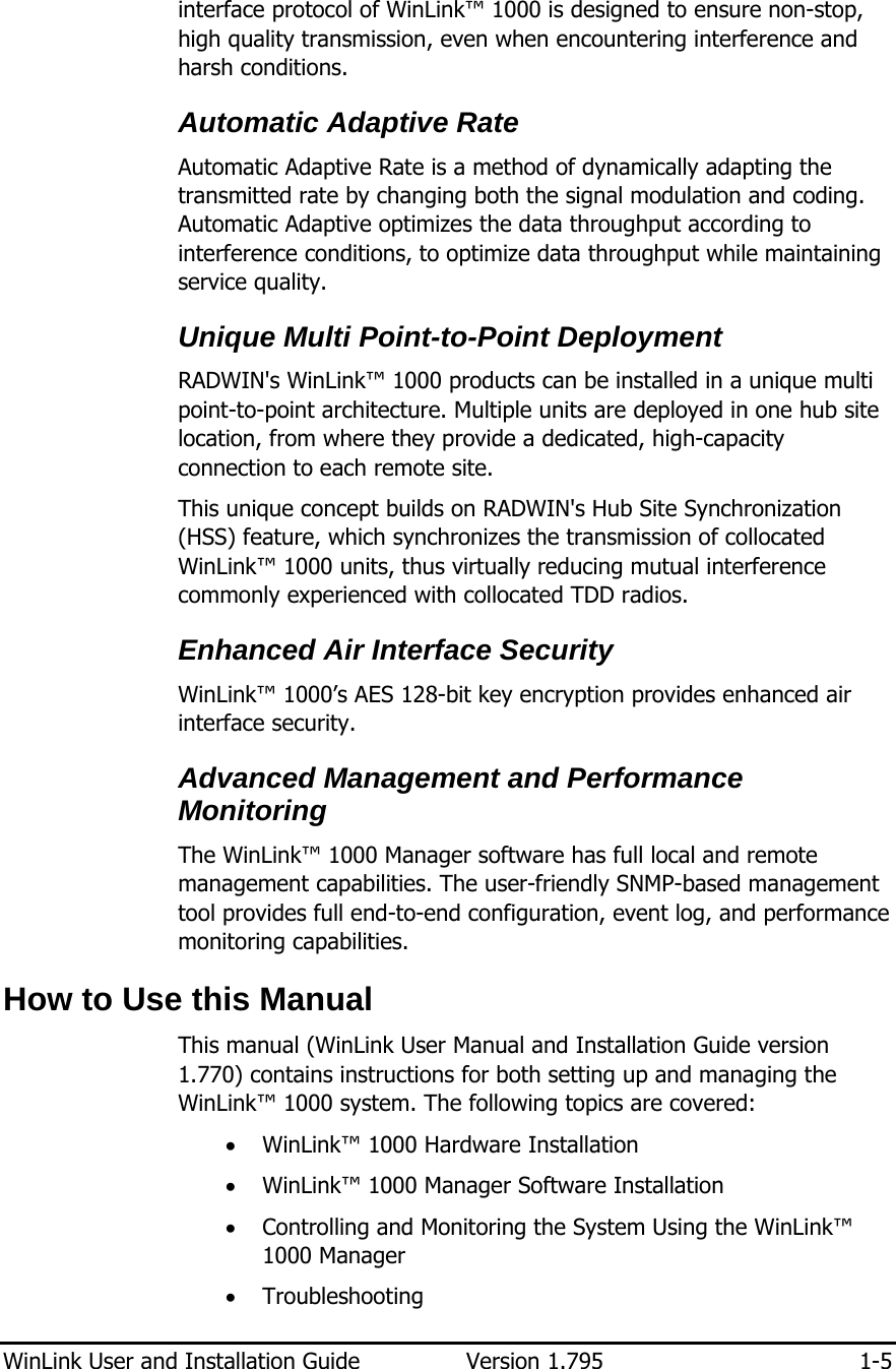
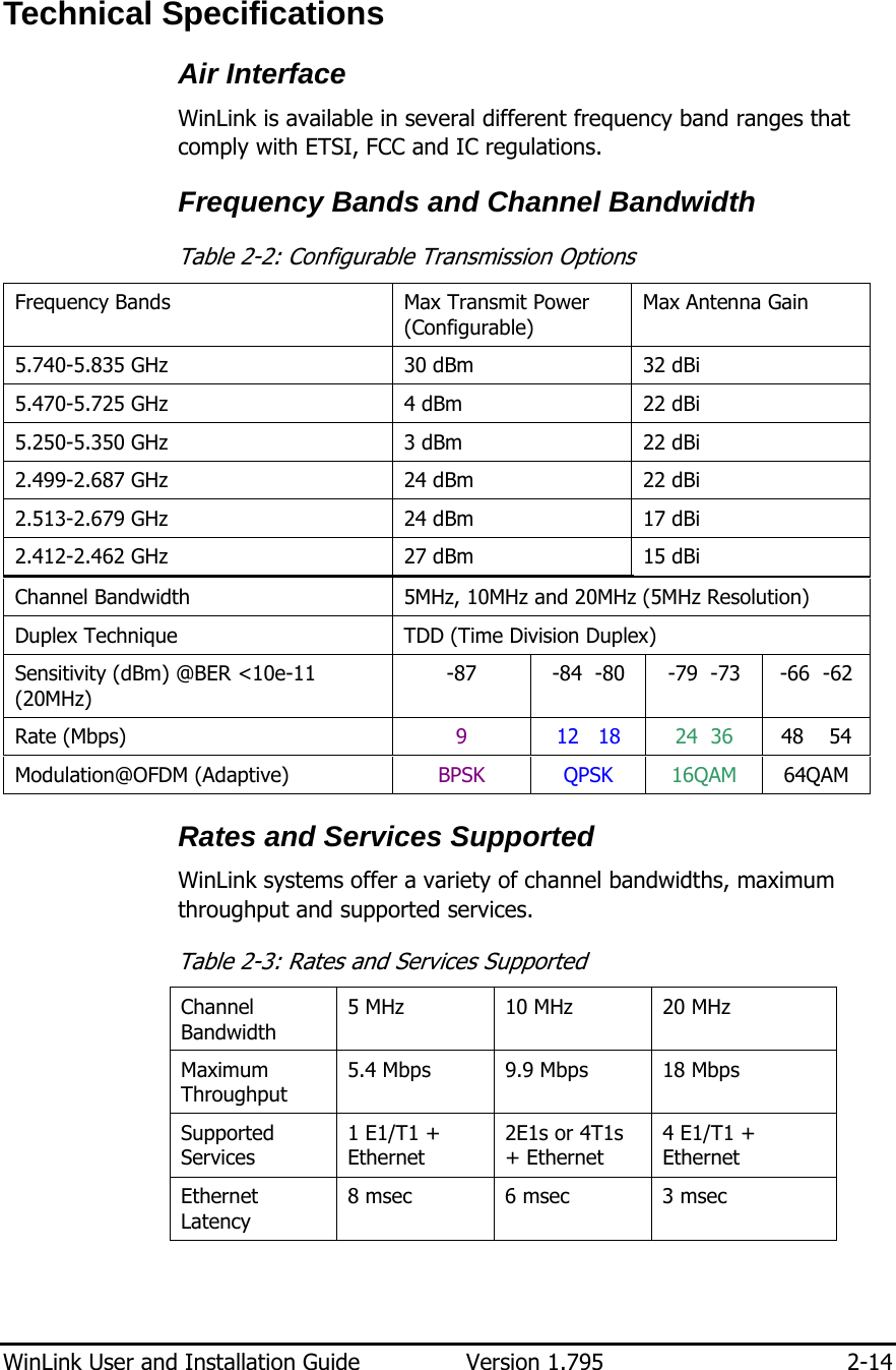
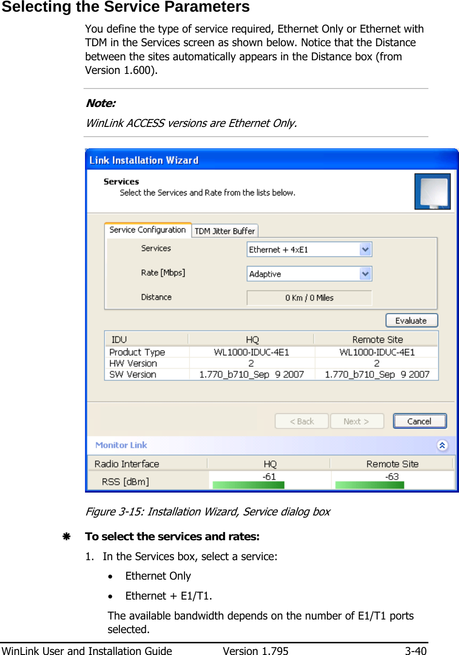
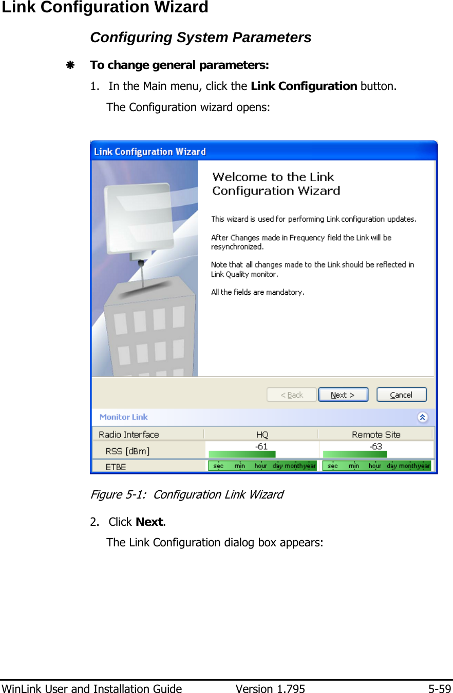
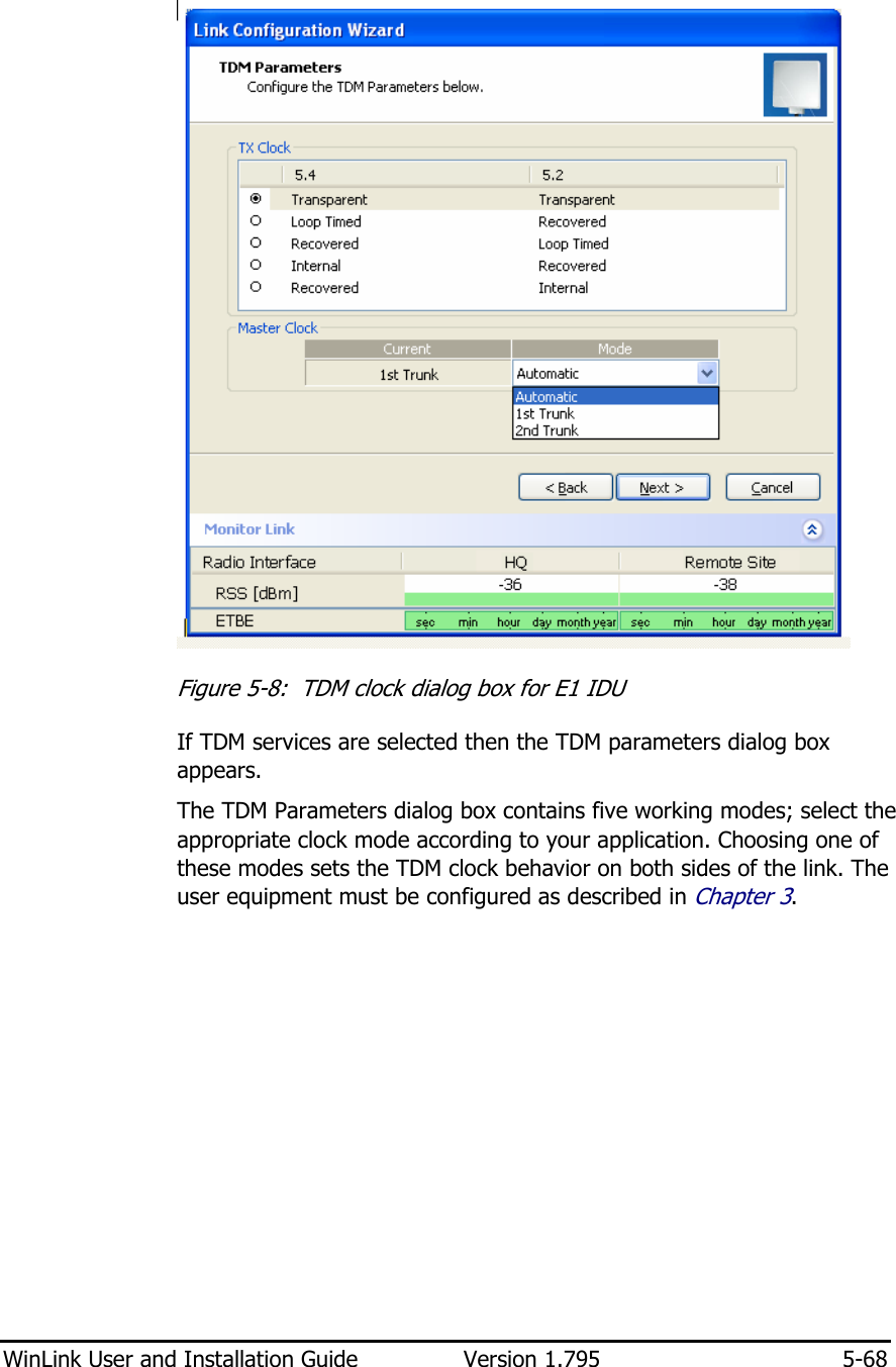
![WinLink User and Installation Guide Version 1.795 2-12 WinLink™ 1000 Manager The WinLink™ 1000 Manager is an SNMP based element and link management application which manages a complete link via a single IP address. It identifies the IP Address, Subnet Mask, and Trap Destination for each Site and also monitors the Radio Interface – RSS [dBm] and Ethernet Service – Rx Rate and Tx Rate. The Manager software facilitates the Link installation and Link configuration between the ODU units. The intuitive, easy-to-use Manager has a graphical MS-Windows interface, and can be utilized locally and remotely. WinLink™ 1000 Manager provides: • Planning tools such as a Link Budget calculator for calculating the expected performance of the WinLink wireless link and the possible configurations for a specific link range. • Installation Wizard • On-line monitoring of air interface quality allowing the administrator to monitor the service and status of each link. • On-line monitoring of equipment alarms and QoS • Local and remote loopback testing • Configuration settings • On-line user manual and help files • Over-the-air software upgrades The WinLink™ 1000 Manager can easily be integrated with any NMS system. Figure 2-13: WinLink™ 1000 Manager screen](https://usermanual.wiki/Radwin/AMWL1540C/User-Guide-1026089-Page-24.png)
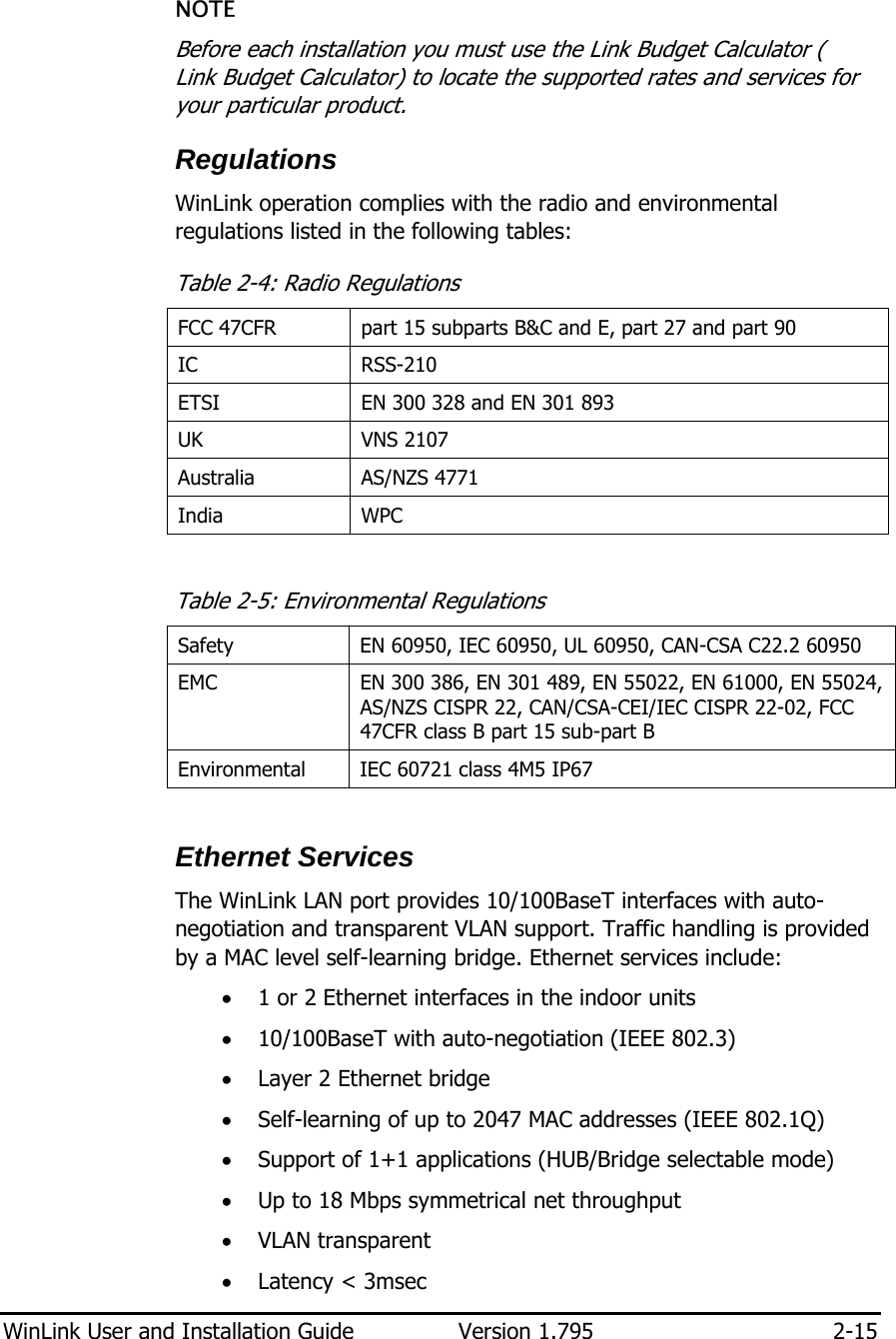
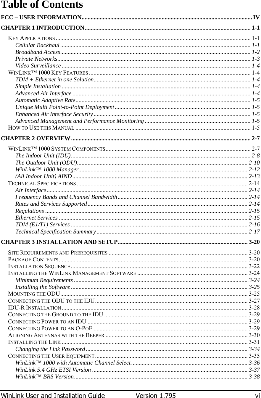
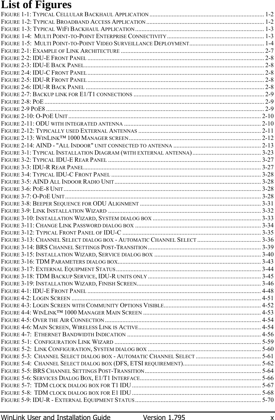
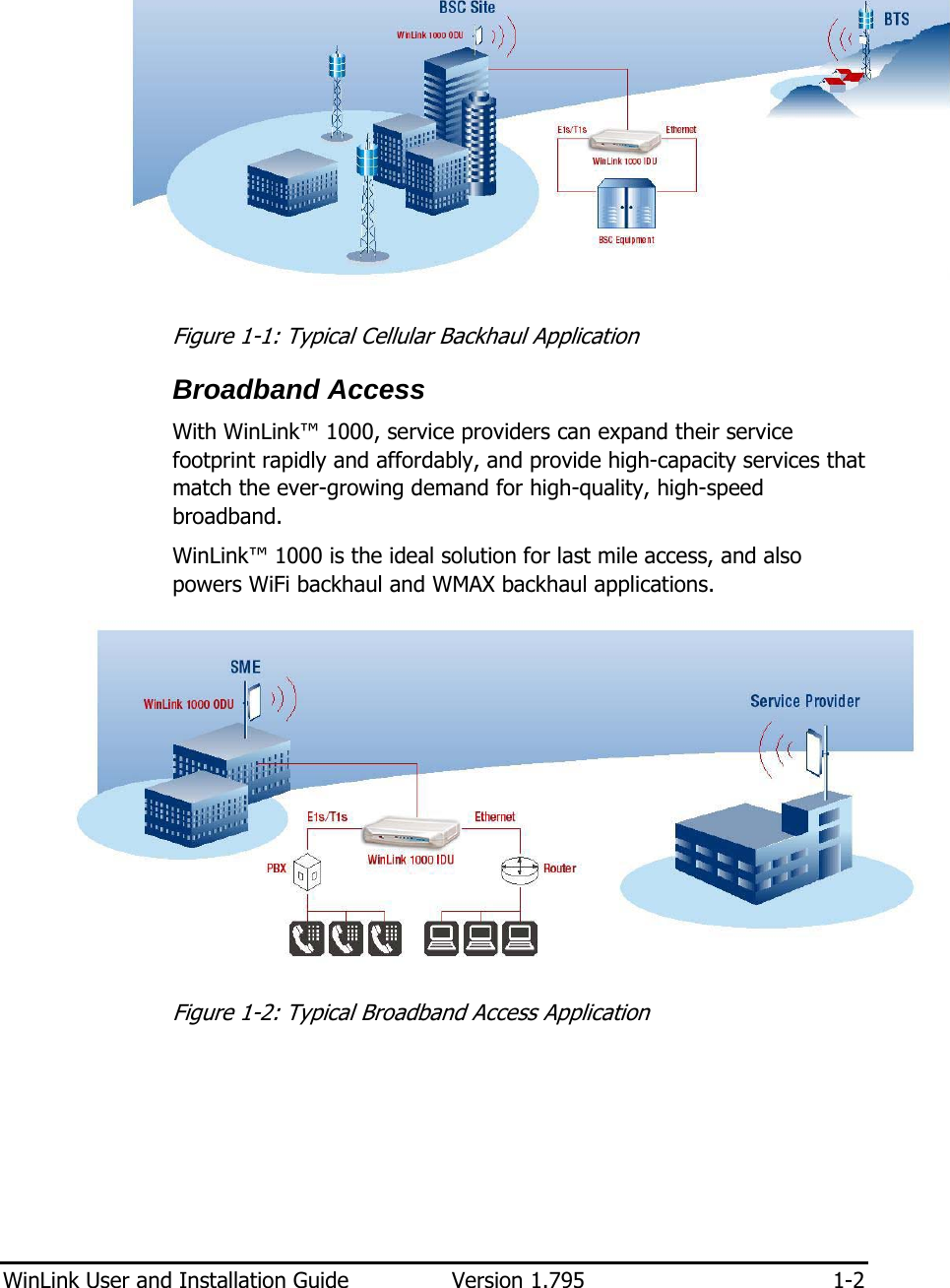
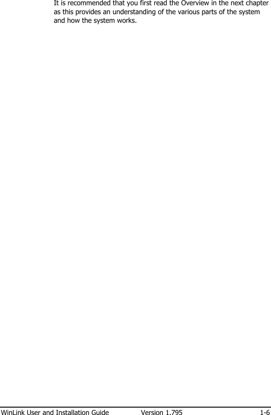
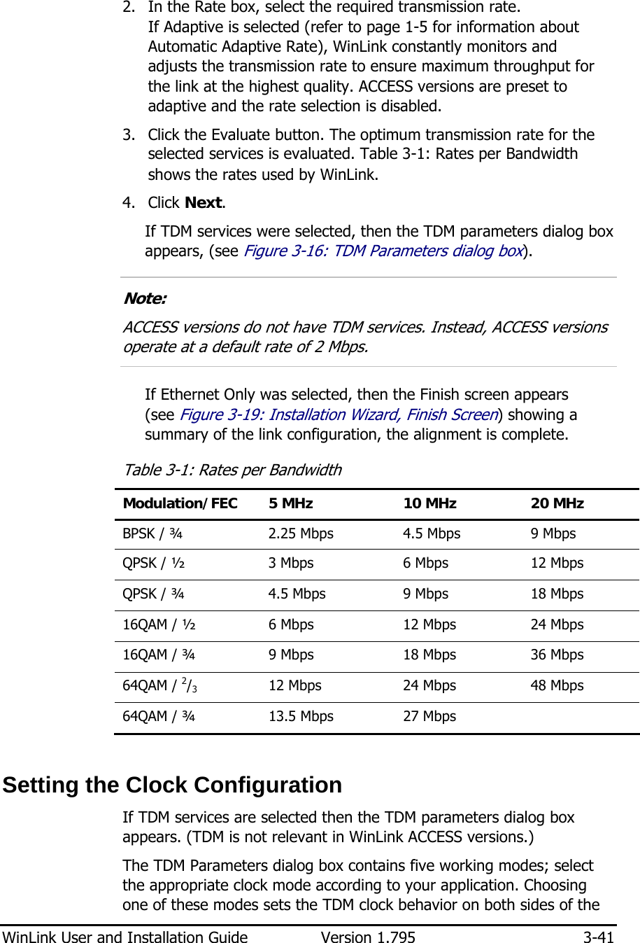
![WinLink User and Installation Guide Version 1.795 2-17 Technical Specification Summary Table 2-6: Technical Specification Summary Air Interface Technology OFDM Duplexing Method Time Division Duplex (TDD) Capacity Configurable up to 54 Mbps Modulation OFDM - BPSK, QPSK, 16QAM, 64QAM Channel Resolution 5/10/20 MHz (ETSI systems do not support 5/10) (BRS systems Single and Double only) Transmitter Power Specification is different per product, for further details refer to the Link Budget Calculator Range Up to 41 km (25.5 miles) Up to 80 km (50 miles) with an external antenna ACCESS versions up to 20 km. Frequency Bands [GHz] 2.3-2.7GHz, 4.9-6GHz. Antennas (See Antenna Characteristics in Antenna) LAN Interface PHY Up to 2 × 10/100BaseT, auto-sensing Framing/Coding IEEE 802.3/U Bridging Self-learning, up to 2048 MAC addresses Line Impedance 100Ω VLAN Support Transparent Frame Size 1536 bytes max for IDU 1800 bytes max for POE Connector RJ-45 E1 Interface Data Rate Unframed (transparent) 2.048 Mbps Line Code HDB3 Connector RJ-45 No. of Ports IDU-E: 1 or 2 IDU-C: 4 T1 Interface Data Rate Unframed (transparent) 1.544 Mbps Line Code AMI, B8ZS Connector RJ-45 No. Of Ports IDU-E: 1 or 2 IDU-C: 4](https://usermanual.wiki/Radwin/AMWL1540C/User-Guide-1026089-Page-29.png)
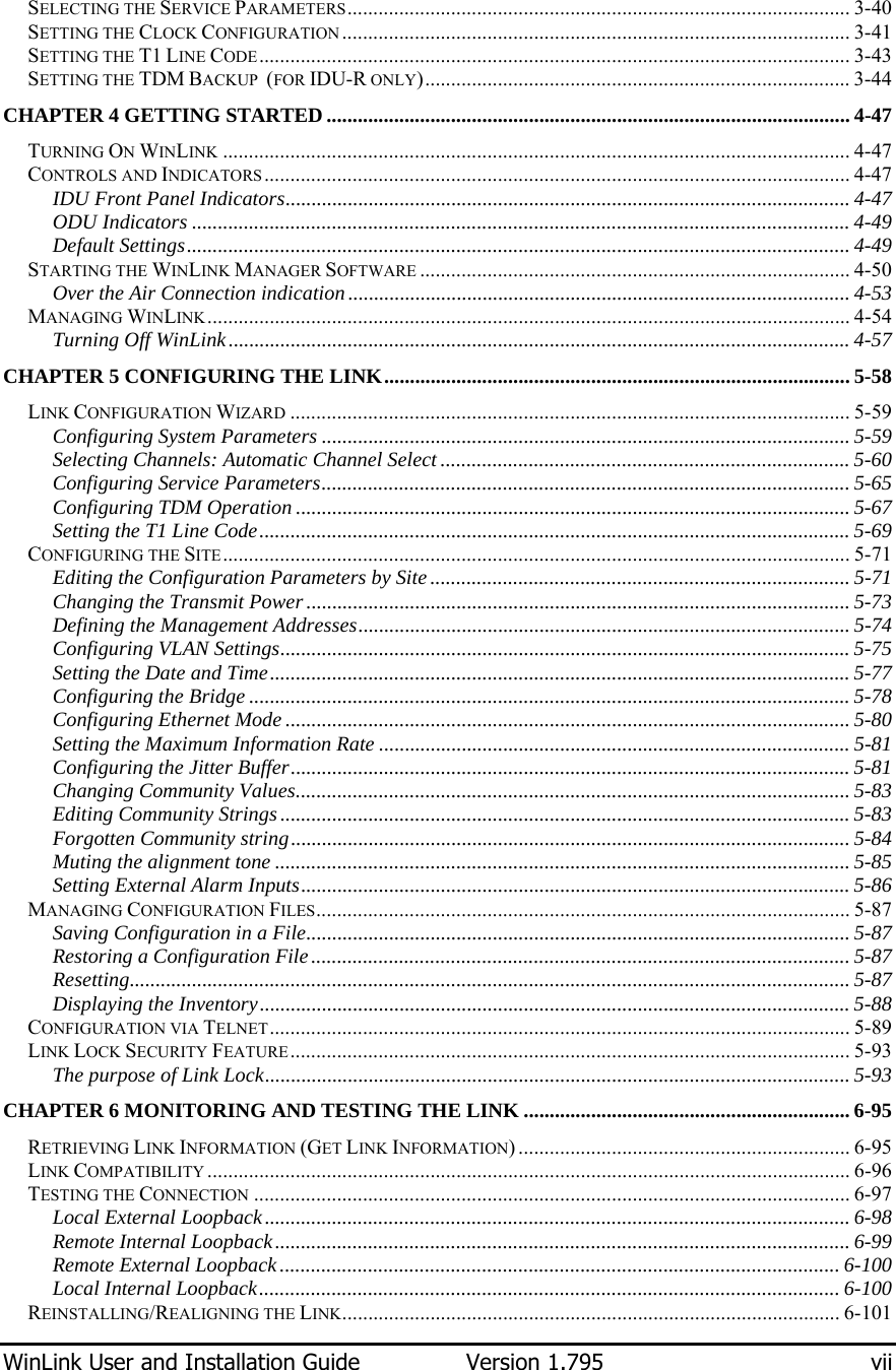
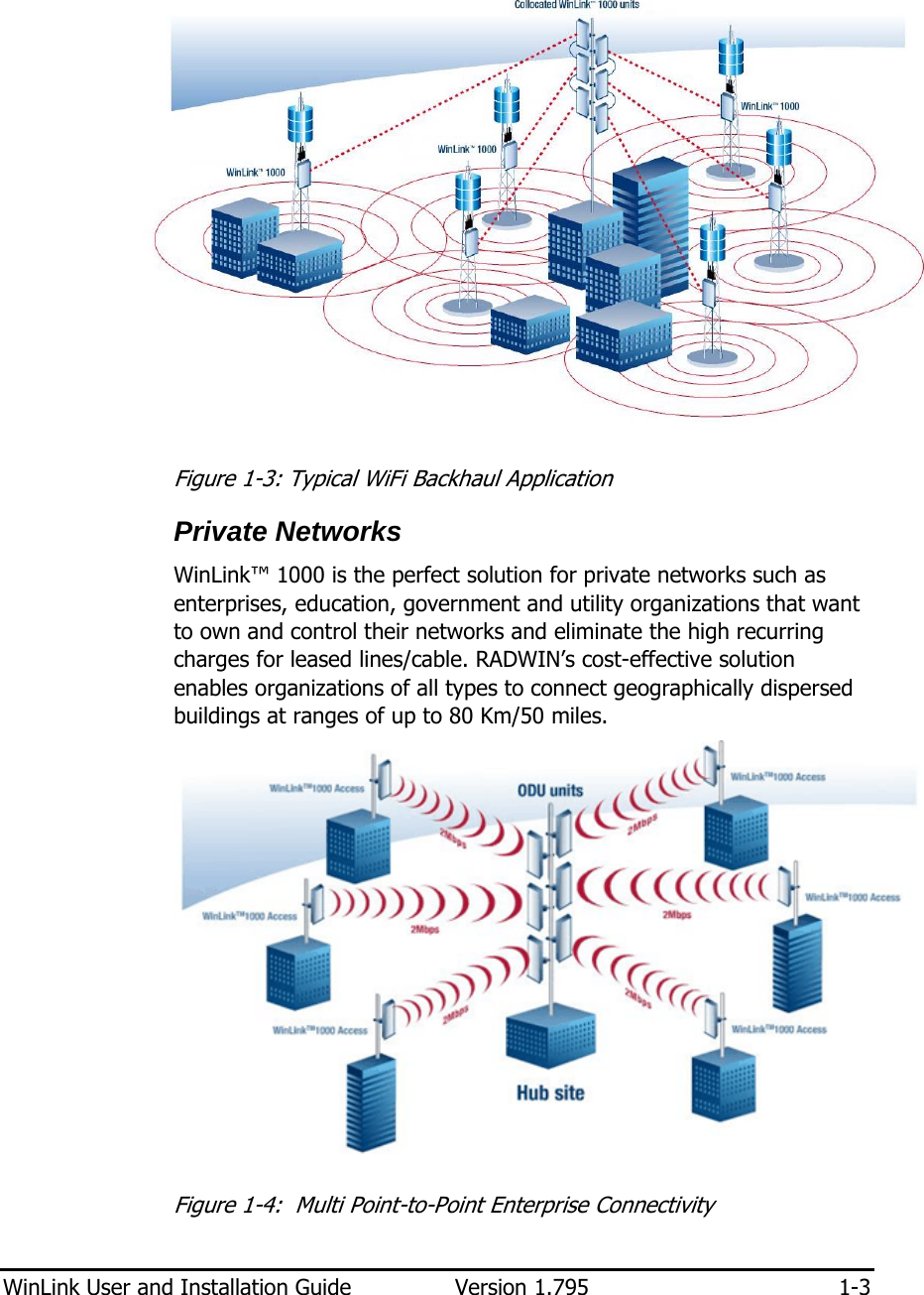
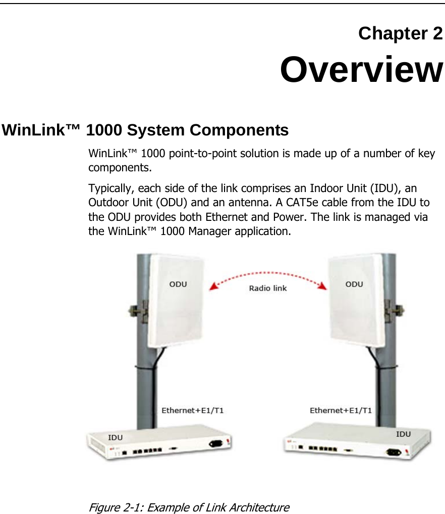
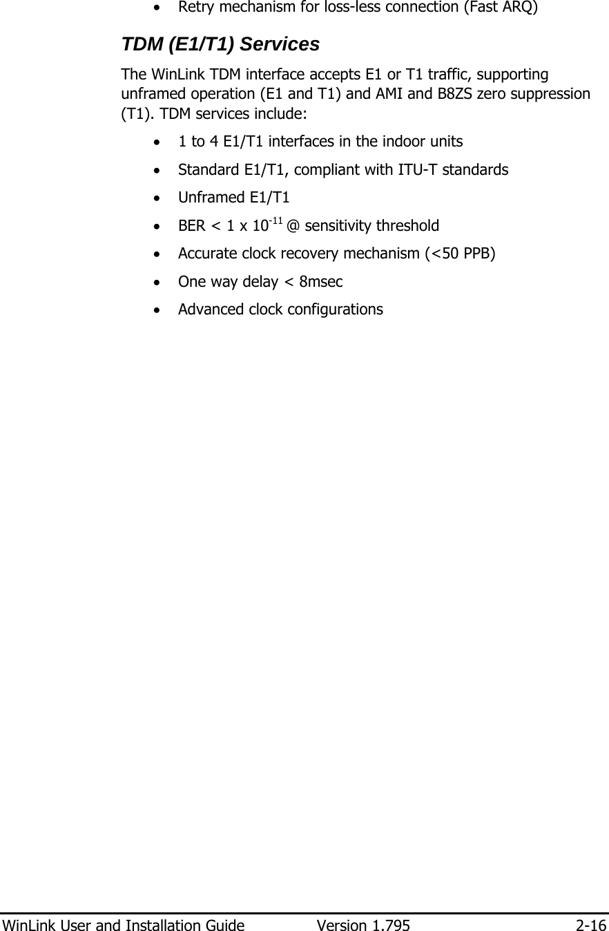
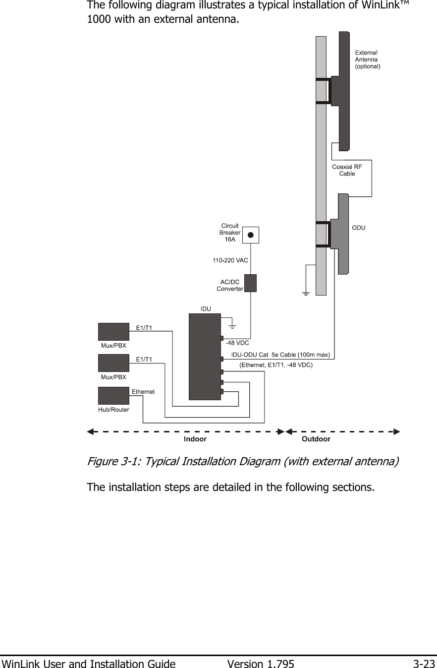
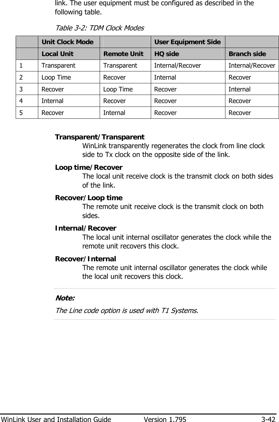
![Chapter 3 Installation and Setup This section describes the installation, alignment, and setup procedures for a WinLink system. Site Requirements and Prerequisites For the IDU units, allow at least 90 cm (36 in) of frontal clearance for operating and maintenance accessibility. Allow at least 10 cm (4 in) clearance at the rear of the unit for signal lines and interface cables. The ambient operating temperature should be –45 to 60°C/–49 to 140°F (ODU), or –5 to 45°C/23 to 113°F (IDU) at a relative humidity of up to 90%, non-condensing. Package Contents The WinLink packages include the following items: ODU package containing: • ODU • Mast/Wall mounting kit plus mounting instructions • CD-ROM [WinLink™ 1000 Manager, Installation and Operation Manual, and Link Budget Calculator] • Self adhesive label showing the MAC address and the alternative community string KEY. Keep this label safe. • Spare RJ-45 connector IDU-E or IDU-R package containing: • IDU-E or IDU-R • AC/DC Converter • IDU wall-mounting drilling template • Self adhesive label showing the IDU LED operation • Spare RJ-45 connector IDU-C Package containing: • IDU-C](https://usermanual.wiki/Radwin/AMWL1540C/User-Guide-1026089-Page-32.png)
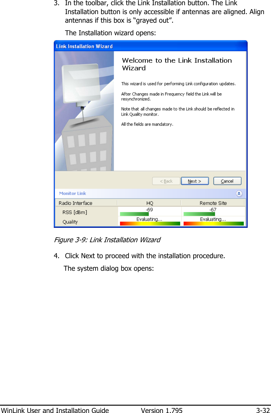
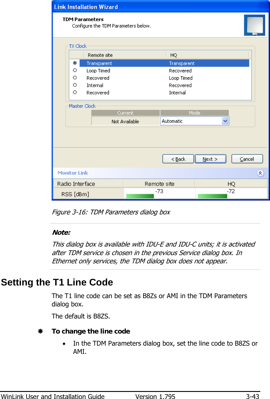
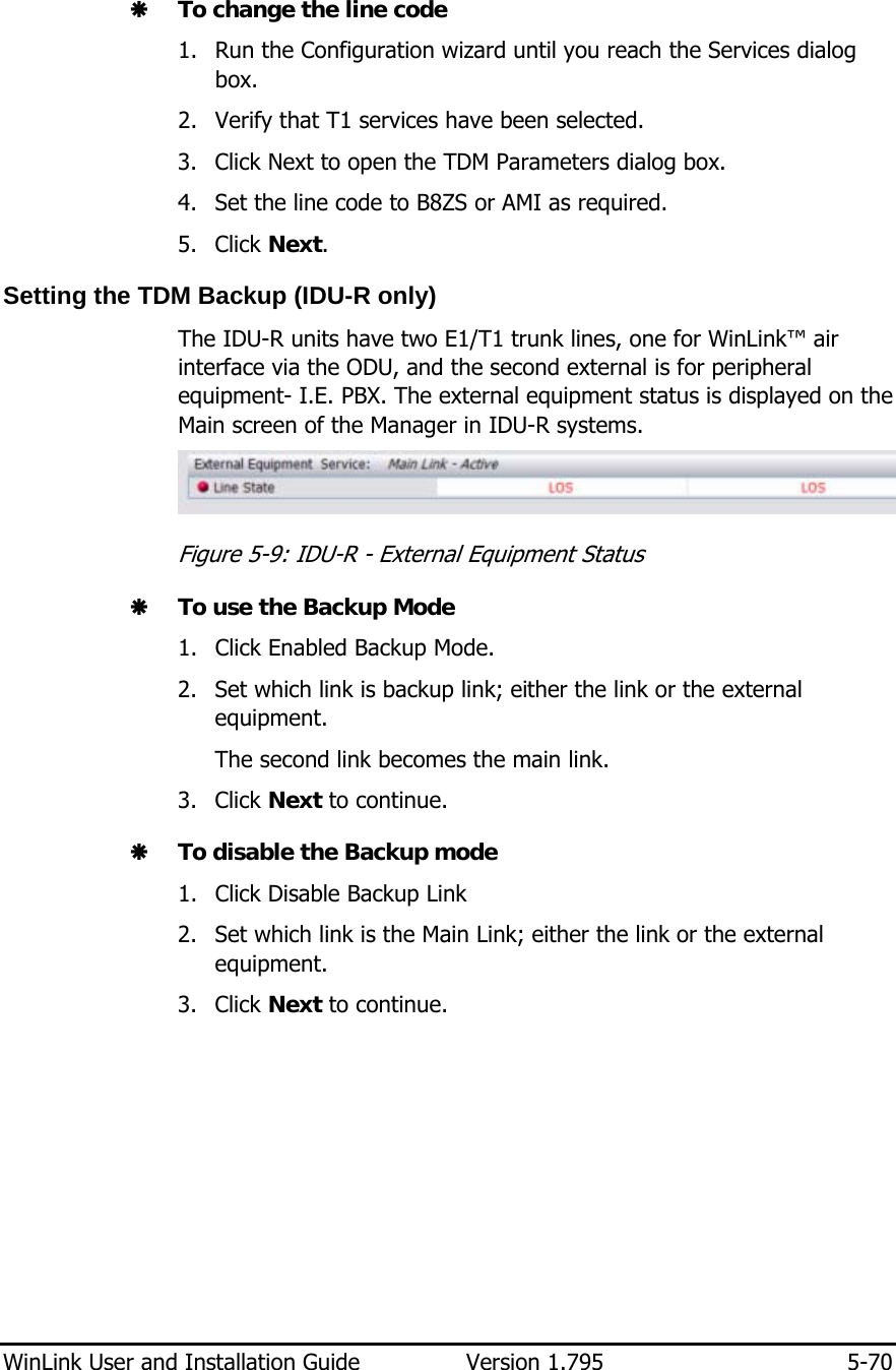
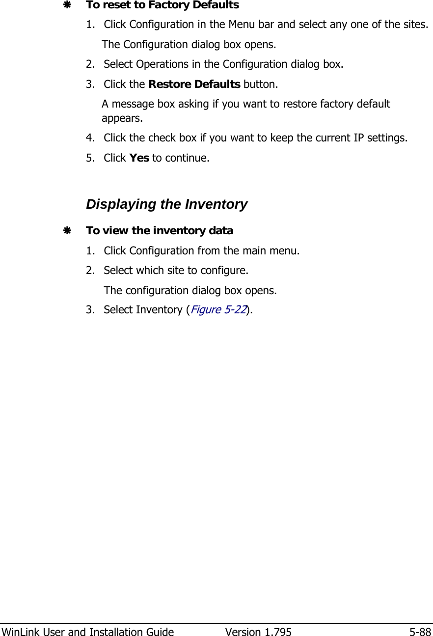
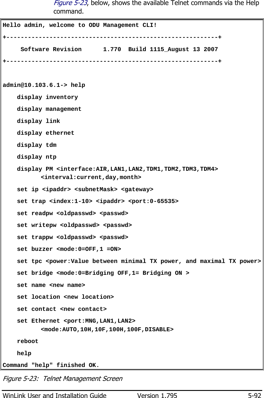
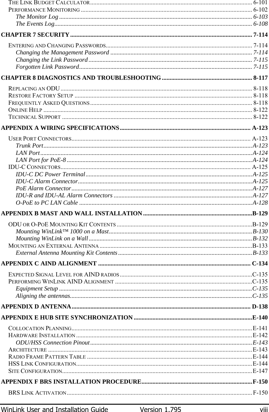
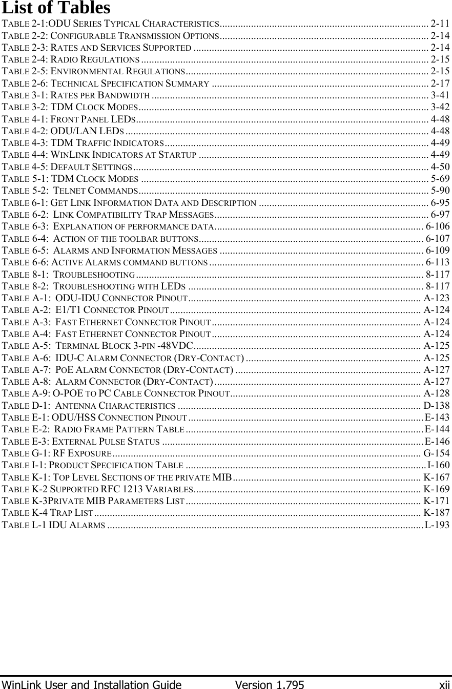
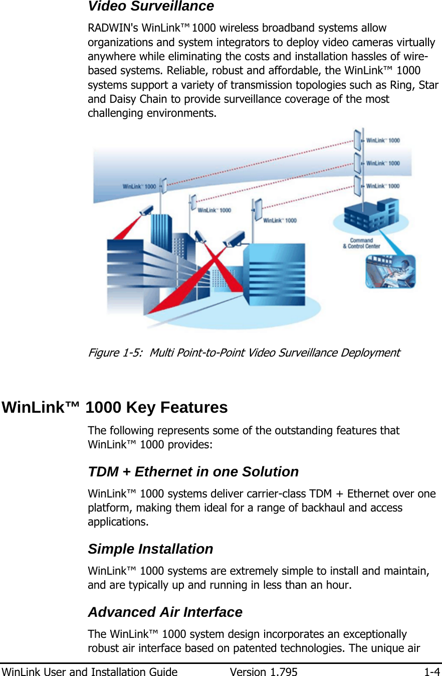
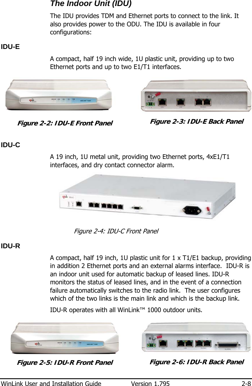
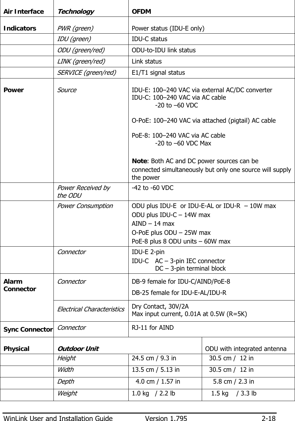
![WinLink User and Installation Guide Version 1.795 5-90 Table 5-2: Telnet Commands Command Explanation display inventory Displays ODU product name, Name, Location, hardware and software revisions, uptime, MAC address, IDU product name, IDU software and hardware revisions Display management Displays IP, Subnet, Gateway, Traps table display link Displays State, SSID, Channel BW, RSS, TSL, Frequency/ACS, DFS, Rate/ARA, Distance display Ethernet Displays Bridge Mode, Aging time, Port table (State, Status and action) display tdm Displays Clock Mode, Master Clock Mode, Current Clock, Quality[1], TDM table (Line status, Error Blocks) display ntp Displays Time, Server and Offset set ip <ipaddr> <subnetMask> <gateway> Set the ODU IP address, subnet mask and gateway The user must reset the ODU after the command completion display PM <interface:AIR,LAN1,LAN2,TDM1, TDM2,TDM3,TDM4> <interval:current,day,month> Shows the performance monitor tables for each interface according to user defined monitoring intervals set trap <index:1-10> <ipaddr> <port:0-65535> Set a specific trap from the traps table (set trap 3 10.0.0.133 162) set readpw <oldpasswd> <passwd> Set the read access password (read community) set writepw <oldpasswd> <passwd> Set the read-write access password (read-write community) set trappw <oldpasswd> <passwd> Set the trap community string set buzzer <mode:0=OFF,1 =ON> Toggle the buzzer mode (0 – off, 1 – on) set tpc<power:Value between minimal TX power, and maximal TX power> Set the ODU transmit power. If a wrong value is entered, both min and max values shall be displayed in the error reply set bridge <mode:0=Bridging OFF,1= Bridging ON > Set the ODU bridge mode (0 – off, 1 – on) set name <new name> Set the name of the link set location <new location> Set the name of the location Set contact <new contact> Set the name of the site manager set Ethernet <>port:MNG,LAN1,LAN2> <mode:AUTO,10H,10F,100H,100F,DISABLE> Set the mode and speed of each ethernet port](https://usermanual.wiki/Radwin/AMWL1540C/User-Guide-1026089-Page-102.png)