Radwin AMWL1540C Outdoor radio unit operating in 5.3 GHz and 5.4 GHz bands User Manual UM 1 795 1
Radwin Ltd. Outdoor radio unit operating in 5.3 GHz and 5.4 GHz bands UM 1 795 1
Radwin >
User manual
WinLink™ 1000
Broadband Wireless
Transmission System
User Manual and
Installation Guide
Version 1.795.1

WinLink User and Installation Guide Version 1.795 ii
WinLink™ 1000
User Manual and Installation Guide
Notice
This manual contains information that is proprietary to RADWIN Ltd. ("RADWIN"). No part of this
publication may be reproduced in any form whatsoever without prior written approval by RADWIN
Ltd.
Right, title and interest, all information, copyrights, patents, know-how, trade secrets and other
intellectual property or other proprietary rights relating to this manual and to the WinLink™ 1000
and any software components contained therein are proprietary products of RADWIN protected
under international copyright law and shall be and remain solely with RADWIN.
WinLink™ 1000 is a registered trademark of RADWIN. No right, license, or interest to such
trademark is granted hereunder, and you agree that no such right, license, or interest shall be
asserted by you with respect to such trademark.
You shall not copy, reverse compile or reverse assemble all or any portion of the Manual or the
WinLink™ 1000. You are prohibited from, and shall not, directly or indirectly, develop, market,
distribute, license, or sell any product that supports substantially similar functionality as the
WinLink™ 1000 based on or derived in any way from the WinLink™ 1000. Your undertaking in this
paragraph shall survive the termination of this Agreement.
This Agreement is effective upon your opening of the WinLink™ 1000 package and shall continue
until terminated. RADWIN may terminate this Agreement upon the breach by you of any term
hereof. Upon such termination by RADWIN, you agree to return to RADWIN the WinLink™ 1000 and
all copies and portions thereof.
For further information contact RADWIN at the address below or contact your local distributor.
RADWIN Corporate Headquarters 27 Habarzel Street, Tel Aviv, 69710, Israel Tel:
+972.3.766.2900 Fax: +972.3.766.2902

WinLink User and Installation Guide Version 1.795 iii
RADWIN Worldwide Offices
Corporate Headquarters
27 Habarzel Street
Tel Aviv, 69710
Israel
Tel: +972.3.766.2917
Support Headquarters
27 Habarzel Street
Tel Aviv, 69710
Israel
Tel: +972.3.766.2900
Mobile: +972.54.766.0044
North America Headquarters
900 Corporate Drive
Mahwah, NJ 07430
USA
Tel (1): 1.800.444.7234 / 341
Tel (2): +1.201.529.1100 / 341
Latin America Headquarters
Rua Grao Mogol 828
Belo Horizonte, MG 30310-010
Brazil
Tel (1): +55.31.919.76.402
Tel (2): +972.54.7586808
India Headquarters
Mohan Co-operative Industrial Estate
E-13, B-1 Extn
New Delhi, 110044
India
Tel: +91.11.40539180
APAC Headquarters
1 Jalan Kuala #13-01
The Morningside, 239639
Singapore
Tel: +65.9878.3004
Indonesia Sales Office
Jl. Jenderal Sudirman Kav. 86
Jakarta, 10220
Indonesia
Tel: +62.8138.570.0657
Philippines Sales Office
37A. A luna St. West Rembo
Makati City, 1200
Philippines
Tel: +63.2882.6886
Mobile: +63.9178923427
China Sales Office
Asian Games Village
Huiyuan Gongyu J1312
Beijing 100101
China
Tel: +86-010-84980629
For sales support contact: sales@Radwin.com
For technical support contact: support@Radwin.com
For technical support in India only, contact: support-india@Radwin.com

WinLink User and Installation Guide Version 1.795 iv
FCC – User Information
This equipment has been tested and found to comply with the limits for a Class B digital
device, pursuant to Part 15 of the FCC Rules. These limits are designed to provide reasonable
protection against harmful interference in a residential installation. This equipment generates,
uses and can radiate radio frequency energy and, if not installed and used in accordance with
the instructions, may cause harmful interference to radio communications. However, there is
no guarantee that interference will not occur in a particular installation. If this equipment does
cause harmful interference to radio or television reception, which can be determined by
turning the equipment off and on, the user is encouraged to try to correct the interference by
one or more of the following measures:
-- Reorient or relocate the receiving antenna.
-- Increase the separation between the equipment and receiver.
-- Connect the equipment into an outlet on a circuit different from that to which the receiver is
connected.
Consult the dealer or an experienced radio/TV technician for help.
Changes or modifications to this equipment not expressly approved by the party responsible
for compliance (WinLink™ 1000) could void the user’s authority to operate the equipment.
WARNING:
It is the responsibility of the installer to ensure that when using the outdoor antenna kits in
the United States (or where FCC rules apply), only those antennas certified with the product
are used. The use of any antenna other than those certified with the product is expressly
forbidden in accordance to FCC rules CFR47 part 15.204.
The installer should configure the output power level of antennas, according to country
regulations and per antenna type.
Note:
Outdoor units and antennas should be installed ONLY by experienced installation professionals
who are familiar with local building and safety codes and, wherever applicable, are licensed by
the appropriate government regulatory authorities. Failure to do so may void the WinLink™
1000 warranty and may expose the end user or the service provider to legal and financial
liabilities. RADWIN and its resellers or distributors are not liable for injury, damage or violation
of regulations associated with the installation of outdoor units or antennas.

WinLink User and Installation Guide Version 1.795 v
FCC Notation for Indoor Units IDU-E and IDU-C
Concerning all models and configurations
This device complies with part 15 of the FCC Rules. Operation is subject to the following two
conditions:
(1) This device may not cause harmful interference.
(2) This device must accept any interference received, including interference that may cause
undesired operation.
Canadian Emission Requirements for Indoor Units
This Class B digital apparatus complies with Canadian ICES-003.
Cet appareil numẻrique de la classe B est conforme ả la norme NMB-003 du Canada.

WinLink User and Installation Guide Version 1.795 vi
Table of Contents
FCC – USER INFORMATION.................................................................................................................IV
CHAPTER 1 INTRODUCTION.............................................................................................................. 1-1
KEY APPLICATIONS ................................................................................................................................. 1-1
Cellular Backhaul.............................................................................................................................. 1-1
Broadband Access.............................................................................................................................. 1-2
Private Networks................................................................................................................................ 1-3
Video Surveillance ............................................................................................................................. 1-4
WINLINK™ 1000 KEY FEATURES ........................................................................................................... 1-4
TDM + Ethernet in one Solution........................................................................................................ 1-4
Simple Installation............................................................................................................................. 1-4
Advanced Air Interface ...................................................................................................................... 1-4
Automatic Adaptive Rate.................................................................................................................... 1-5
Unique Multi Point-to-Point Deployment..........................................................................................1-5
Enhanced Air Interface Security........................................................................................................ 1-5
Advanced Management and Performance Monitoring ...................................................................... 1-5
HOW TO USE THIS MANUAL .................................................................................................................... 1-5
CHAPTER 2 OVERVIEW....................................................................................................................... 2-7
WINLINK™ 1000 SYSTEM COMPONENTS................................................................................................ 2-7
The Indoor Unit (IDU)....................................................................................................................... 2-8
The Outdoor Unit (ODU)................................................................................................................. 2-10
WinLink™ 1000 Manager................................................................................................................ 2-12
(All Indoor Unit) AIND.................................................................................................................... 2-13
TECHNICAL SPECIFICATIONS ................................................................................................................. 2-14
Air Interface..................................................................................................................................... 2-14
Frequency Bands and Channel Bandwidth...................................................................................... 2-14
Rates and Services Supported.......................................................................................................... 2-14
Regulations ...................................................................................................................................... 2-15
Ethernet Services ............................................................................................................................. 2-15
TDM (E1/T1) Services ..................................................................................................................... 2-16
Technical Specification Summary.................................................................................................... 2-17
CHAPTER 3 INSTALLATION AND SETUP...................................................................................... 3-20
SITE REQUIREMENTS AND PREREQUISITES ............................................................................................ 3-20
PACKAGE CONTENTS............................................................................................................................. 3-20
INSTALLATION SEQUENCE ..................................................................................................................... 3-22
INSTALLING THE WINLINK MANAGEMENT SOFTWARE ......................................................................... 3-24
Minimum Requirements ................................................................................................................... 3-24
Installing the Software ..................................................................................................................... 3-25
MOUNTING THE ODU............................................................................................................................ 3-25
CONNECTING THE ODU TO THE IDU..................................................................................................... 3-27
IDU-R INSTALLATION ........................................................................................................................... 3-28
CONNECTING THE GROUND TO THE IDU ............................................................................................... 3-29
CONNECTING POWER TO AN IDU .......................................................................................................... 3-29
CONNECTING POWER TO AN O-POE ...................................................................................................... 3-29
ALIGNING ANTENNAS WITH THE BEEPER .............................................................................................. 3-30
INSTALLING THE LINK ........................................................................................................................... 3-31
Changing the Link Password........................................................................................................... 3-34
CONNECTING THE USER EQUIPMENT..................................................................................................... 3-35
WinLink™ 1000 with Automatic Channel Select............................................................................. 3-36
WinLink 5.4 GHz ETSI Version ....................................................................................................... 3-37
WinLink™ BRS Version................................................................................................................... 3-38

WinLink User and Installation Guide Version 1.795 vii
SELECTING THE SERVICE PARAMETERS................................................................................................. 3-40
SETTING THE CLOCK CONFIGURATION .................................................................................................. 3-41
SETTING THE T1 LINE CODE.................................................................................................................. 3-43
SETTING THE TDM BACKUP (FOR IDU-R ONLY).................................................................................. 3-44
CHAPTER 4 GETTING STARTED..................................................................................................... 4-47
TURNING ON WINLINK ......................................................................................................................... 4-47
CONTROLS AND INDICATORS ................................................................................................................. 4-47
IDU Front Panel Indicators............................................................................................................. 4-47
ODU Indicators ............................................................................................................................... 4-49
Default Settings................................................................................................................................ 4-49
STARTING THE WINLINK MANAGER SOFTWARE ................................................................................... 4-50
Over the Air Connection indication................................................................................................. 4-53
MANAGING WINLINK............................................................................................................................ 4-54
Turning Off WinLink........................................................................................................................ 4-57
CHAPTER 5 CONFIGURING THE LINK.......................................................................................... 5-58
LINK CONFIGURATION WIZARD ............................................................................................................ 5-59
Configuring System Parameters ...................................................................................................... 5-59
Selecting Channels: Automatic Channel Select ............................................................................... 5-60
Configuring Service Parameters...................................................................................................... 5-65
Configuring TDM Operation ........................................................................................................... 5-67
Setting the T1 Line Code.................................................................................................................. 5-69
CONFIGURING THE SITE......................................................................................................................... 5-71
Editing the Configuration Parameters by Site................................................................................. 5-71
Changing the Transmit Power......................................................................................................... 5-73
Defining the Management Addresses...............................................................................................5-74
Configuring VLAN Settings.............................................................................................................. 5-75
Setting the Date and Time................................................................................................................ 5-77
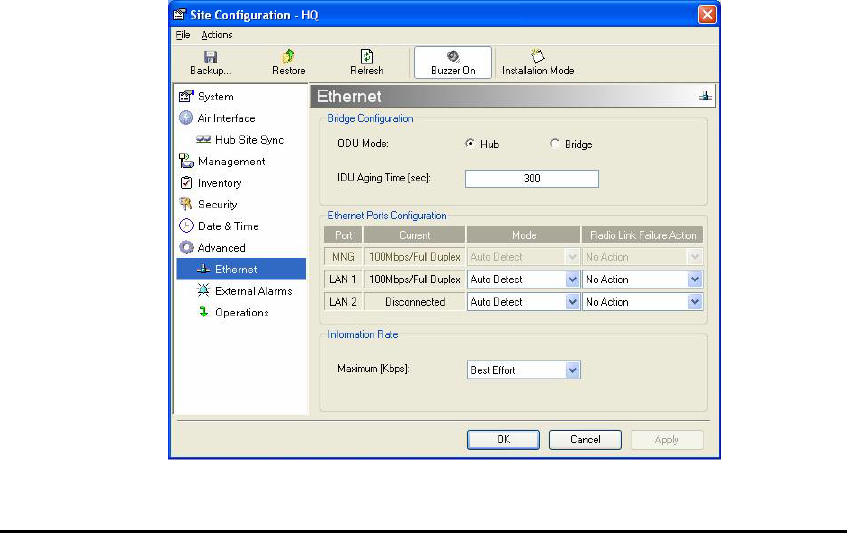
Configuring the Bridge .................................................................................................................... 5-78
Configuring Ethernet Mode ............................................................................................................. 5-80
Setting the Maximum Information Rate ........................................................................................... 5-81
Configuring the Jitter Buffer............................................................................................................ 5-81
Changing Community Values........................................................................................................... 5-83
Editing Community Strings.............................................................................................................. 5-83
Forgotten Community string............................................................................................................ 5-84
Muting the alignment tone ............................................................................................................... 5-85
Setting External Alarm Inputs.......................................................................................................... 5-86
MANAGING CONFIGURATION FILES....................................................................................................... 5-87
Saving Configuration in a File......................................................................................................... 5-87
Restoring a Configuration File........................................................................................................ 5-87
Resetting........................................................................................................................................... 5-87
Displaying the Inventory.................................................................................................................. 5-88
CONFIGURATION VIA TELNET................................................................................................................ 5-89
LINK LOCK SECURITY FEATURE ............................................................................................................ 5-93
The purpose of Link Lock................................................................................................................. 5-93
CHAPTER 6 MONITORING AND TESTING THE LINK ............................................................... 6-95
RETRIEVING LINK INFORMATION (GET LINK INFORMATION) ................................................................ 6-95
LINK COMPATIBILITY ............................................................................................................................ 6-96
TESTING THE CONNECTION ................................................................................................................... 6-97
Local External Loopback................................................................................................................. 6-98
Remote Internal Loopback............................................................................................................... 6-99
Remote External Loopback............................................................................................................ 6-100
Local Internal Loopback................................................................................................................ 6-100
REINSTALLING/REALIGNING THE LINK................................................................................................ 6-101

WinLink User and Installation Guide Version 1.795 viii
THE LINK BUDGET CALCULATOR........................................................................................................ 6-101
PERFORMANCE MONITORING .............................................................................................................. 6-102
The Monitor Log ............................................................................................................................ 6-103
The Events Log............................................................................................................................... 6-108
CHAPTER 7 SECURITY..................................................................................................................... 7-114
ENTERING AND CHANGING PASSWORDS.............................................................................................. 7-114
Changing the Management Password ........................................................................................... 7-114
Changing the Link Password......................................................................................................... 7-115
Forgotten Link Password............................................................................................................... 7-115
CHAPTER 8 DIAGNOSTICS AND TROUBLESHOOTING.......................................................... 8-117
REPLACING AN ODU ........................................................................................................................... 8-118
RESTORE FACTORY SETUP .................................................................................................................. 8-118
FREQUENTLY ASKED QUESTIONS ........................................................................................................ 8-118
ONLINE HELP ...................................................................................................................................... 8-122
TECHNICAL SUPPORT .......................................................................................................................... 8-122
APPENDIX A WIRING SPECIFICATIONS.................................................................................... A-123
USER PORT CONNECTORS................................................................................................................... A-123
Trunk Port......................................................................................................................................A-123
LAN Port........................................................................................................................................A-124
LAN Port for PoE-8.......................................................................................................................A-124
IDU-C CONNECTORS.......................................................................................................................... A-125
IDU-C DC Power Terminal...........................................................................................................A-125
IDU-C Alarm Connector................................................................................................................A-125
PoE Alarm Connector....................................................................................................................A-127
IDU-R and IDU-AL Alarm Connectors .........................................................................................A-127
O-PoE to PC LAN Cable ...............................................................................................................A-128
APPENDIX B MAST AND WALL INSTALLATION......................................................................B-129
ODU OR O-POE MOUNTING KIT CONTENTS .......................................................................................B-129
Mounting WinLink™ 1000 on a Mast............................................................................................B-130
Mounting WinLink on a Wall.........................................................................................................B-132
MOUNTING AN EXTERNAL ANTENNA ..................................................................................................B-133
External Antenna Mounting Kit Contents......................................................................................B-133
APPENDIX C AIND ALIGNMENT .................................................................................................. C-134
EXPECTED SIGNAL LEVEL FOR AIND RADIOS .....................................................................................C-135
PERFORMING WINLINK AIND ALIGNMENT ........................................................................................C-135
Equipment Setup ............................................................................................................................C-135
Aligning the antennas.....................................................................................................................C-135
APPENDIX D ANTENNA................................................................................................................... D-138
APPENDIX E HUB SITE SYNCHRONIZATION............................................................................E-140
COLLOCATION PLANNING....................................................................................................................E-141
HARDWARE INSTALLATION .................................................................................................................E-142
ODU/HSS Connection Pinout........................................................................................................E-143
ARCHITECTURE ...................................................................................................................................E-143
RADIO FRAME PATTERN TABLE ..........................................................................................................E-144
HSS LINK CONFIGURATION.................................................................................................................E-144
SITE CONFIGURATION..........................................................................................................................E-147
APPENDIX F BRS INSTALLATION PROCEDURE.......................................................................F-150
BRS LINK ACTIVATION....................................................................................................................... F-150

WinLink User and Installation Guide Version 1.795 ix
BRS LINK CONFIGURATION ................................................................................................................ F-152
APPENDIX G RF EXPOSURE ..........................................................................................................G-154
APPENDIX H LINK BUDGET CALCULATOR............................................................................. H-155
OVERVIEW.......................................................................................................................................... H-155
DESCRIPTION OF PARAMETERS........................................................................................................... H-155
Example 1 ..................................................................................................................................... H-156
Example 2 ..................................................................................................................................... H-156
USING THE LINK BUDGET CALCULATOR ............................................................................................ H-158
APPENDIX I PRODUCT SPECIFICATION TABLE .......................................................................I-160
APPENDIX J LIGHTNING AND GROUNDING GUIDELINES ................................................... J-162
GROUNDING FOR INDOOR/OUTDOOR UNITS .........................................................................................J-162
ODU (Out Door Unit) Grounding ..................................................................................................J-162
IDU (Indoor Unit) Grounding ........................................................................................................J-162
EXTERNAL LIGHTNING SURGE SUPPRESSORS .......................................................................................J-162
INTERNAL ESD PROTECTION CIRCUITS ................................................................................................J-163
APPENDIX K MIB REFERENCE..................................................................................................... K-164
INTRODUCTION ................................................................................................................................... K-164
About the MIB................................................................................................................................K-164
About this Appendix.......................................................................................................................K-164
Terminology...................................................................................................................................K-164
INTERFACE API .................................................................................................................................. K-165
Control Method..............................................................................................................................K-165
Community String ..........................................................................................................................K-166
PRIVATE MIB STRUCTURE ................................................................................................................. K-166
Products MIB.................................................................................................................................K-167
ODU MIB.......................................................................................................................................K-167
IDU MIB ........................................................................................................................................K-168
General MIB ..................................................................................................................................K-168
MIB PARAMETER ............................................................................................................................... K-168
Supported Variables from the RFC 1213 MIB...............................................................................K-169
MIB Parameters List......................................................................................................................K-171
MIB TRAPS ........................................................................................................................................ K-186
General ..........................................................................................................................................K-186
Trap parameters list.......................................................................................................................K-187
APPENDIX L ALARMS SYSTEM SPECIFICATION.....................................................................L-192
ALARMS SYSTEM SPECIFICATION........................................................................................................L-192
INDEX........................................................................................................................................................195

WinLink User and Installation Guide Version 1.795 x
List of Figures
FIGURE 1-1: TYPICAL CELLULAR BACKHAUL APPLICATION ........................................................................ 1-2
FIGURE 1-2: TYPICAL BROADBAND ACCESS APPLICATION .......................................................................... 1-2
FIGURE 1-3: TYPICAL WIFI BACKHAUL APPLICATION ................................................................................. 1-3
FIGURE 1-4: MULTI POINT-TO-POINT ENTERPRISE CONNECTIVITY............................................................. 1-3
FIGURE 1-5: MULTI POINT-TO-POINT VIDEO SURVEILLANCE DEPLOYMENT............................................... 1-4
FIGURE 2-1: EXAMPLE OF LINK ARCHITECTURE .......................................................................................... 2-7
FIGURE 2-2: IDU-E FRONT PANEL ............................................................................................................... 2-8
FIGURE 2-3: IDU-E BACK PANEL................................................................................................................. 2-8
FIGURE 2-4: IDU-C FRONT PANEL............................................................................................................... 2-8
FIGURE 2-5: IDU-R FRONT PANEL............................................................................................................... 2-8
FIGURE 2-6: IDU-R BACK PANEL ................................................................................................................ 2-8
FIGURE 2-7: BACKUP LINK FOR E1/T1 CONNECTIONS .................................................................................. 2-9
FIGURE 2-8: POE .......................................................................................................................................... 2-9
FIGURE 2-9 POE8 ......................................................................................................................................... 2-9
FIGURE 2-10: O-POE UNIT ......................................................................................................................... 2-10
FIGURE 2-11: ODU WITH INTEGRATED ANTENNA ...................................................................................... 2-10
FIGURE 2-12: TYPICALLY USED EXTERNAL ANTENNAS ............................................................................. 2-11
FIGURE 2-13: WINLINK™ 1000 MANAGER SCREEN................................................................................... 2-12
FIGURE 2-14: AIND - "ALL INDOOR" UNIT CONNECTED TO ANTENNA ....................................................... 2-13
FIGURE 3-1: TYPICAL INSTALLATION DIAGRAM (WITH EXTERNAL ANTENNA) ........................................... 3-23
FIGURE 3-2: TYPICAL IDU-E REAR PANEL ................................................................................................ 3-27
FIGURE 3-3: IDU-R REAR PANEL............................................................................................................... 3-27
FIGURE 3-4: TYPICAL IDU-C FRONT PANEL .............................................................................................. 3-28
FIGURE 3-5: AIND ALL INDOOR RADIO UNIT............................................................................................ 3-28
FIGURE 3-6: POE-8 UNIT............................................................................................................................ 3-28
FIGURE 3-7: O-POE UNIT ........................................................................................................................... 3-28
FIGURE 3-8: BEEPER SEQUENCE FOR ODU ALIGNMENT ............................................................................ 3-31
FIGURE 3-9: LINK INSTALLATION WIZARD ................................................................................................ 3-32
FIGURE 3-10: INSTALLATION WIZARD, SYSTEM DIALOG BOX .................................................................... 3-33
FIGURE 3-11: CHANGE LINK PASSWORD DIALOG BOX ............................................................................... 3-34
FIGURE 3-12: TYPICAL FRONT PANEL OF IDU-C ....................................................................................... 3-35
FIGURE 3-13: CHANNEL SELECT DIALOG BOX - AUTOMATIC CHANNEL SELECT ........................................ 3-36
FIGURE 3-14: BRS CHANNEL SETTINGS POST-TRANSITION ....................................................................... 3-39
FIGURE 3-15: INSTALLATION WIZARD, SERVICE DIALOG BOX ................................................................... 3-40
FIGURE 3-16: TDM PARAMETERS DIALOG BOX.......................................................................................... 3-43
FIGURE 3-17: EXTERNAL EQUIPMENT STATUS ........................................................................................... 3-44
FIGURE 3-18: TDM BACKUP SERVICE, IDU-R UNITS ONLY ....................................................................... 3-45
FIGURE 3-19: INSTALLATION WIZARD, FINISH SCREEN.............................................................................. 3-46
FIGURE 4-1: IDU-E FRONT PANEL ............................................................................................................. 4-48
FIGURE 4-2: LOGIN SCREEN ....................................................................................................................... 4-51
FIGURE 4-3: LOGIN SCREEN WITH COMMUNITY OPTIONS VISIBLE............................................................. 4-52
FIGURE 4-4: WINLINK™ 1000 MANAGER MAIN SCREEN .......................................................................... 4-53
FIGURE 4-5: OVER THE AIR CONNECTION .................................................................................................. 4-54
FIGURE 4-6: MAIN SCREEN, WIRELESS LINK IS ACTIVE............................................................................. 4-54
FIGURE 4-7: ETHERNET BANDWIDTH INDICATION .................................................................................... 4-56
FIGURE 5-1: CONFIGURATION LINK WIZARD ............................................................................................ 5-59
FIGURE 5-2: LINK CONFIGURATION, SYSTEM DIALOG BOX ....................................................................... 5-60
FIGURE 5-3: CHANNEL SELECT DIALOG BOX - AUTOMATIC CHANNEL SELECT ......................................... 5-61
FIGURE 5-4: CHANNEL SELECT DIALOG BOX (DFS, ETSI REQUIREMENT)................................................. 5-62
FIGURE 5-5: BRS CHANNEL SETTINGS POST-TRANSITION......................................................................... 5-64
FIGURE 5-6: SERVICES DIALOG BOX, E1/T1 INTERFACE............................................................................ 5-66
FIGURE 5-7: TDM CLOCK DIALOG BOX FOR T1 IDU ................................................................................. 5-67
FIGURE 5-8: TDM CLOCK DIALOG BOX FOR E1 IDU ................................................................................. 5-68
FIGURE 5-9: IDU-R - EXTERNAL EQUIPMENT STATUS ............................................................................... 5-70

WinLink User and Installation Guide Version 1.795 xi
FIGURE 5-10: CONFIGURATION LINK, FINISH SCREEN ............................................................................... 5-71
FIGURE 5-11: CONFIGURATION DIALOG BOX............................................................................................ 5-73
FIGURE 5-12: CHANGING THE TRANSMIT POWER...................................................................................... 5-74
FIGURE 5-13: MANAGEMENT ADDRESSES - SITE CONFIGURATION DIALOG BOX........................................ 5-75
FIGURE 5-14: CONFIGURING VLAN SETTINGS........................................................................................... 5-76
FIGURE 5-15: NTP SERVER ADDRESS - SITE CONFIGURATION DIALOG BOX .............................................. 5-78
FIGURE 5-16: CHANGE DATE AND TIME - HQ DIALOG BOX........................................................................ 5-78
FIGURE 5-17: BRIDGE CONFIGURATION - SITE CONFIGURATION DIALOG BOX ........................................... 5-79
FIGURE 5-18: JITTER BUFFER CONFIGURATION.......................................................................................... 5-82
FIGURE 5-19: CHANGING THE COMMUNITY STRING................................................................................... 5-84
FIGURE 5-20: ALTERNATIVE COMMUNITY DIALOG BOX ........................................................................... 5-85
FIGURE 5-21: EXTERNAL ALARM CONFIGURATION .................................................................................. 5-86
FIGURE 5-22: INVENTORY SCREEN............................................................................................................ 5-89
FIGURE 5-23: TELNET MANAGEMENT SCREEN.......................................................................................... 5-92
FIGURE 6-1: GET LINK INFORMATION DIALOG BOX................................................................................... 6-96
FIGURE 6-2: LOOPBACK DIALOG BOX ......................................................................................................... 6-98
FIGURE 6-3: LOCAL EXTERNAL LOOPBACK............................................................................................... 6-99
FIGURE 6-4: REMOTE INTERNAL LOOPBACK .............................................................................................. 6-99
FIGURE 6-5: REMOTE EXTERNAL LOOPBACK ........................................................................................... 6-100
FIGURE 6-6: LOCAL INTERNAL LOOPBACK.............................................................................................. 6-100
FIGURE 6-7: WINLINK™ 1000 - LINK BUDGET CALCULATOR ................................................................. 6-102
FIGURE 6-8: PREFERENCES DIALOG BOX .................................................................................................. 6-103
FIGURE 6-9: PERFORMANCE MONITORING REPORT WINDOW.................................................................. 6-104
FIGURE 6-10: THRESHOLD CONFIGURATION DIALOG BOX ........................................................................ 6-108
FIGURE 6-11: EVENTS LOG DISPLAY........................................................................................................ 6-110
FIGURE 6-12: PREFERENCES DIALOG BOX ................................................................................................ 6-111
FIGURE 6-13: ACTIVE ALARMS SUMMARY............................................................................................... 6-113
FIGURE 8-1: ONLINE HELP FOR WINLINK™ 1000.................................................................................... 8-122
FIGURE A-1: EXAMPLE FOR CONNECTING THE ALARM CONNECTOR ....................................................... A-126
FIGURE B-1: LARGE CLAMP ....................................................................................................................B-129
FIGURE B-2: SMALL CLAMP.....................................................................................................................B-129
FIGURE B-3: ARM ....................................................................................................................................B-129
FIGURE B-4: MOUNTING ON A MAST........................................................................................................B-130
FIGURE B-5: MOUNTI NG ON A WALL ......................................................................................................B-132
FIGURE C-1: WINLINK LINK SETUP .........................................................................................................C-134
FIGURE E-1: INTERFERENCE CAUSED BY COLLOCATED UNITS ..................................................................E-140
FIGURE E-2: COLLOCATED UNITS USING HUB SITE SYNCHRONIZATION...................................................E-141
FIGURE E-3: COLLOCATION SITE CALCULATOR.......................................................................................E-141
FIGURE E-4: HSS INTERCONNECTION UNIT ............................................................................................E-142
FIGURE E-5: HSS TYPICAL APPLICATION ................................................................................................E-144
FIGURE E-6: HUB SITE SYNCHRONIZATION SETTINGS DIALOG BOX ........................................................E-145
FIGURE E-7: HUB SITE CONFIGURATION DIALOG BOX .............................................................................E-147
FIGURE E-8: SITE CONFIGURATION – HUB SITE SYNC DIALOG BOX .........................................................E-148
FIGURE E-9: HSS NOT SUPPORTED..........................................................................................................E-149
FIGURE F-1: INACTIVE MANAGER SCREEN............................................................................................... F-150
FIGURE F-2: BRS AIR INTERFACE DIALOG BOX ....................................................................................... F-151
FIGURE F-3: BRS CHANNEL SETTINGS PRE-TRANSITION ........................................................................ F-152
FIGURE F-4: BRS CHANNEL SETTINGS POST-TRANSITION ...................................................................... F-153
FIGURE H-1: ACCESSING THE LINK BUDGET MANAGER CALCULATOR................................................... H-155
FIGURE H-2: LINK BUDGET SCREEN ....................................................................................................... H-157
FIGURE H-3: CLIMATE AND TERRAIN FACTOR ........................................................................................ H-157
FIGURE H-4: GEOGRAPHICAL CONDITIONS ............................................................................................. H-158
FIGURE H-5: FRESNEL ZONE ................................................................................................................... H-158

WinLink User and Installation Guide Version 1.795 xii
List of Tables
TABLE 2-1:ODU SERIES TYPICAL CHARACTERISTICS................................................................................ 2-11
TABLE 2-2: CONFIGURABLE TRANSMISSION OPTIONS................................................................................ 2-14
TABLE 2-3: RATES AND SERVICES SUPPORTED .......................................................................................... 2-14
TABLE 2-4: RADIO REGULATIONS .............................................................................................................. 2-15
TABLE 2-5: ENVIRONMENTAL REGULATIONS............................................................................................. 2-15
TABLE 2-6: TECHNICAL SPECIFICATION SUMMARY ................................................................................... 2-17
TABLE 3-1: RATES PER BANDWIDTH .......................................................................................................... 3-41
TABLE 3-2: TDM CLOCK MODES............................................................................................................... 3-42
TABLE 4-1: FRONT PANEL LEDS................................................................................................................ 4-48
TABLE 4-2: ODU/LAN LEDS.................................................................................................................... 4-48
TABLE 4-3: TDM TRAFFIC INDICATORS..................................................................................................... 4-49
TABLE 4-4: WINLINK INDICATORS AT STARTUP ........................................................................................ 4-49
TABLE 4-5: DEFAULT SETTINGS ................................................................................................................. 4-50
TABLE 5-1: TDM CLOCK MODES .............................................................................................................. 5-69
TABLE 5-2: TELNET COMMANDS............................................................................................................... 5-90
TABLE 6-1: GET LINK INFORMATION DATA AND DESCRIPTION ................................................................. 6-95
TABLE 6-2: LINK COMPATIBILITY TRAP MESSAGES.................................................................................. 6-97
TABLE 6-3: EXPLANATION OF PERFORMANCE DATA................................................................................ 6-106
TABLE 6-4: ACTION OF THE TOOLBAR BUTTONS...................................................................................... 6-107
TABLE 6-5: ALARMS AND INFORMATION MESSAGES .............................................................................. 6-109
TABLE 6-6: ACTIVE ALARMS COMMAND BUTTONS .................................................................................. 6-113
TABLE 8-1: TROUBLESHOOTING.............................................................................................................. 8-117
TABLE 8-2: TROUBLESHOOTING WITH LEDS.......................................................................................... 8-117
TABLE A-1: ODU-IDU CONNECTOR PINOUT......................................................................................... A-123
TABLE A-2: E1/T1 CONNECTOR PINOUT................................................................................................ A-124
TABLE A-3: FAST ETHERNET CONNECTOR PINOUT ................................................................................ A-124
TABLE A-4: FAST ETHERNET CONNECTOR PINOUT ................................................................................ A-124
TABLE A-5: TERMINAL BLOCK 3-PIN -48VDC....................................................................................... A-125
TABLE A-6: IDU-C ALARM CONNECTOR (DRY-CONTACT) ................................................................... A-125
TABLE A-7: POE ALARM CONNECTOR (DRY-CONTACT) ....................................................................... A-127
TABLE A-8: ALARM CONNECTOR (DRY-CONTACT) ............................................................................... A-127
TABLE A-9: O-POE TO PC CABLE CONNECTOR PINOUT......................................................................... A-128
TABLE D-1: ANTENNA CHARACTERISTICS ............................................................................................. D-138
TABLE E-1: ODU/HSS CONNECTION PINOUT ..........................................................................................E-143
TABLE E-2: RADIO FRAME PATTERN TABLE ...........................................................................................E-144
TABLE E-3: EXTERNAL PULSE STATUS ....................................................................................................E-146
TABLE G-1: RF EXPOSURE...................................................................................................................... G-154
TABLE I-1: PRODUCT SPECIFICATION TABLE ............................................................................................I-160
TABLE K-1: TOP LEVEL SECTIONS OF THE PRIVATE MIB........................................................................ K-167
TABLE K-2 SUPPORTED RFC 1213 VARIABLES....................................................................................... K-169
TABLE K-3PRIVATE MIB PARAMETERS LIST .......................................................................................... K-171
TABLE K-4 TRAP LIST............................................................................................................................. K-187
TABLE L-1 IDU ALARMS .........................................................................................................................L-193

WinLink User and Installation Guide Version 1.795 1-1
Chapter 1
Introduction
RADWIN's WinLink™1000 family of wireless broadband products
deliver carrier-class performance at the most competitive price.
WinLink™1000 products pack legacy TDM and Ethernet services over
the 2.3 - 2.7 GHz and 4.9 - 5.95 GHz spectrum bands, and comply with
worldwide standards and regulations (including FCC and ETSI).
RADWIN's carrier-class WinLink™ 1000 products meet the stringent
performance and quality demands of cellular carriers and service
providers. Delivering high capacity connectivity of up to 48 Mbps at
distances of up to 80 Km/50 miles, the WinLink™ 1000 products offer
an unmatched combination of robustness and reliability at an
affordable price.
Key Applications
RADWIN's WinLink™ 1000 systems are ideally suited to meet the
needs of cellular carriers, service providers and private networks (such
as private and public enterprises, government, educational and
financial institutions).
The WinLink™1000 systems power a range of applications, among
them:
• Cellular Backhaul
• Broadband Access
• Private Network Connectivity
• Video Surveillance
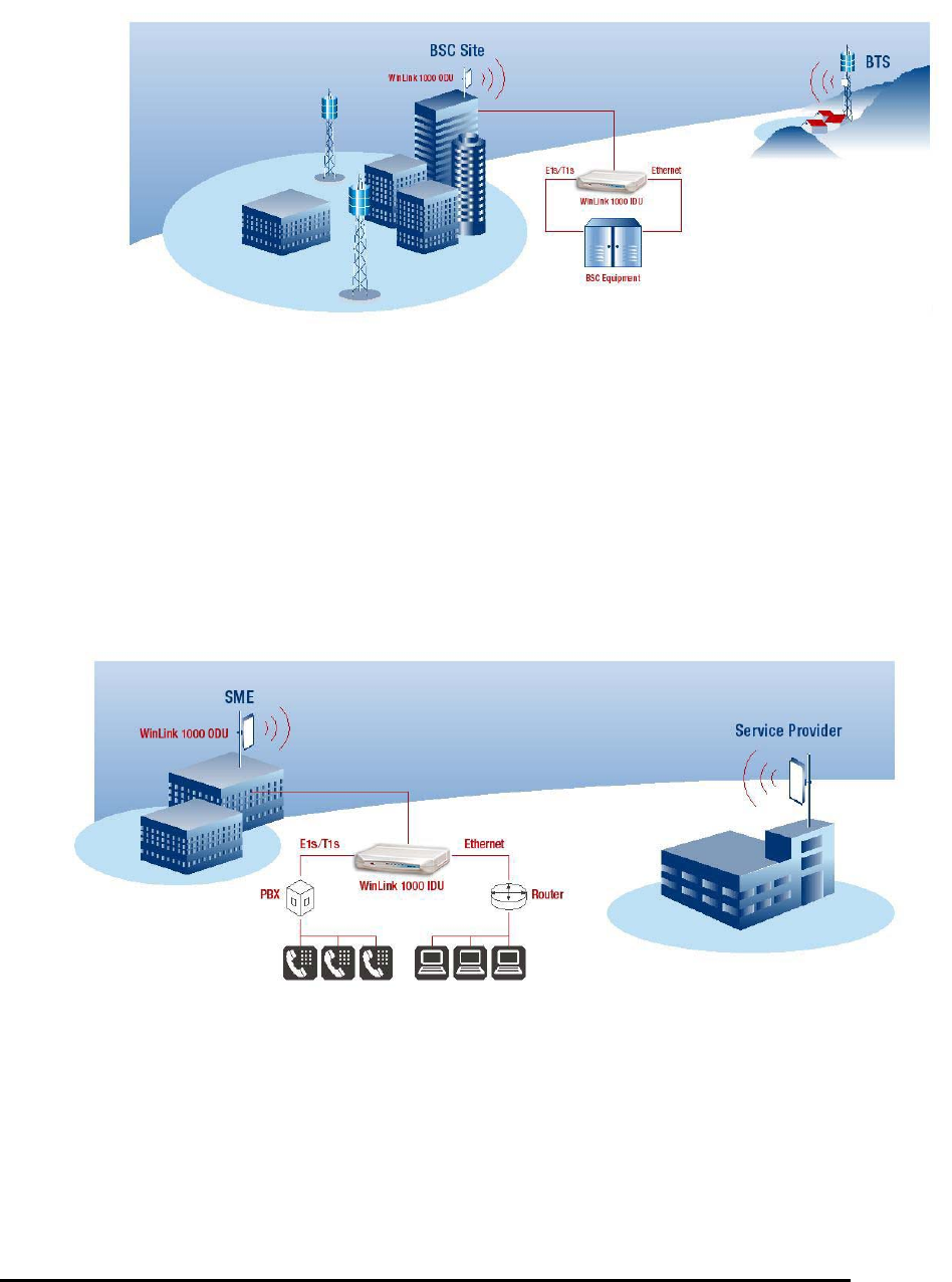
Cellular Backhaul
WinLink™ 1000 products enable cellular carriers to expand their
networks in both urban and rural areas quickly and cost-effectively.
WinLink™ 1000 systems are ideally suited for a broad range of cellular
backhaul deployment scenarios; they empower carriers to expand their
presence into remote and low ARPU areas, provide enhanced overlay
coverage in urban spots, and can serve as a temporary or backup
backhaul solution.
WinLink User and Installation Guide Version 1.795 1-2
Figure 1-1: Typical Cellular Backhaul Application
Broadband Access
With WinLink™ 1000, service providers can expand their service
footprint rapidly and affordably, and provide high-capacity services that
match the ever-growing demand for high-quality, high-speed
broadband.
WinLink™ 1000 is the ideal solution for last mile access, and also
powers WiFi backhaul and WMAX backhaul applications.
Figure 1-2: Typical Broadband Access Application
WinLink User and Installation Guide Version 1.795 1-3
Figure 1-3: Typical WiFi Backhaul Application
Private Networks
WinLink™ 1000 is the perfect solution for private networks such as
enterprises, education, government and utility organizations that want
to own and control their networks and eliminate the high recurring
charges for leased lines/cable. RADWIN’s cost-effective solution
enables organizations of all types to connect geographically dispersed
buildings at ranges of up to 80 Km/50 miles.
Figure 1-4: Multi Point-to-Point Enterprise Connectivity

WinLink User and Installation Guide Version 1.795 1-4
Video Surveillance
RADWIN's WinLink™ 1000 wireless broadband systems allow
organizations and system integrators to deploy video cameras virtually
anywhere while eliminating the costs and installation hassles of wire-
based systems. Reliable, robust and affordable, the WinLink™ 1000
systems support a variety of transmission topologies such as Ring, Star
and Daisy Chain to provide surveillance coverage of the most
challenging environments.
Figure 1-5: Multi Point-to-Point Video Surveillance Deployment
WinLink™ 1000 Key Features
The following represents some of the outstanding features that
WinLink™ 1000 provides:
TDM + Ethernet in one Solution
WinLink™ 1000 systems deliver carrier-class TDM + Ethernet over one
platform, making them ideal for a range of backhaul and access
applications.
Simple Installation
WinLink™ 1000 systems are extremely simple to install and maintain,
and are typically up and running in less than an hour.
Advanced Air Interface
The WinLink™ 1000 system design incorporates an exceptionally
robust air interface based on patented technologies. The unique air

WinLink User and Installation Guide Version 1.795 1-5
interface protocol of WinLink™ 1000 is designed to ensure non-stop,
high quality transmission, even when encountering interference and
harsh conditions.
Automatic Adaptive Rate
Automatic Adaptive Rate is a method of dynamically adapting the
transmitted rate by changing both the signal modulation and coding.
Automatic Adaptive optimizes the data throughput according to
interference conditions, to optimize data throughput while maintaining
service quality.
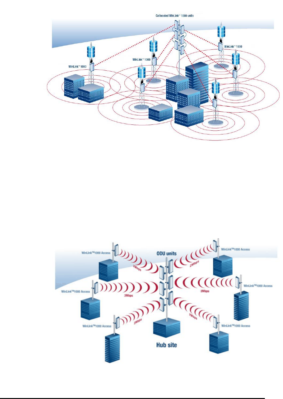
Unique Multi Point-to-Point Deployment
RADWIN's WinLink™ 1000 products can be installed in a unique multi
point-to-point architecture. Multiple units are deployed in one hub site
location, from where they provide a dedicated, high-capacity
connection to each remote site.
This unique concept builds on RADWIN's Hub Site Synchronization
(HSS) feature, which synchronizes the transmission of collocated
WinLink™ 1000 units, thus virtually reducing mutual interference
commonly experienced with collocated TDD radios.
Enhanced Air Interface Security
WinLink™ 1000’s AES 128-bit key encryption provides enhanced air
interface security.
Advanced Management and Performance
Monitoring
The WinLink™ 1000 Manager software has full local and remote
management capabilities. The user-friendly SNMP-based management
tool provides full end-to-end configuration, event log, and performance
monitoring capabilities.
How to Use this Manual
This manual (WinLink User Manual and Installation Guide version
1.770) contains instructions for both setting up and managing the
WinLink™ 1000 system. The following topics are covered:
• WinLink™ 1000 Hardware Installation
• WinLink™ 1000 Manager Software Installation
• Controlling and Monitoring the System Using the WinLink™
1000 Manager
• Troubleshooting

WinLink User and Installation Guide Version 1.795 1-6
It is recommended that you first read the Overview in the next chapter
as this provides an understanding of the various parts of the system
and how the system works.
Chapter 2
Overview
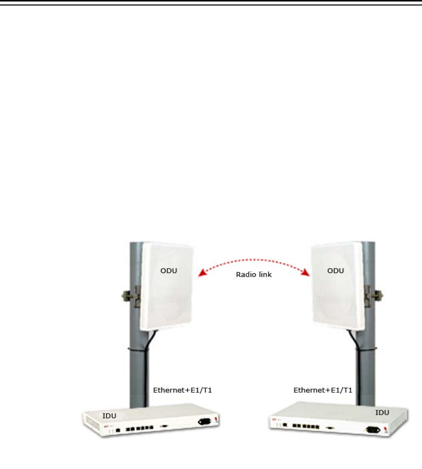
WinLink™ 1000 System Components
WinLink™ 1000 point-to-point solution is made up of a number of key
components.
Typically, each side of the link comprises an Indoor Unit (IDU), an
Outdoor Unit (ODU) and an antenna. A CAT5e cable from the IDU to
the ODU provides both Ethernet and Power. The link is managed via
the WinLink™ 1000 Manager application.
Figure 2-1: Example of Link Architecture
WinLink User and Installation Guide Version 1.795 2-8
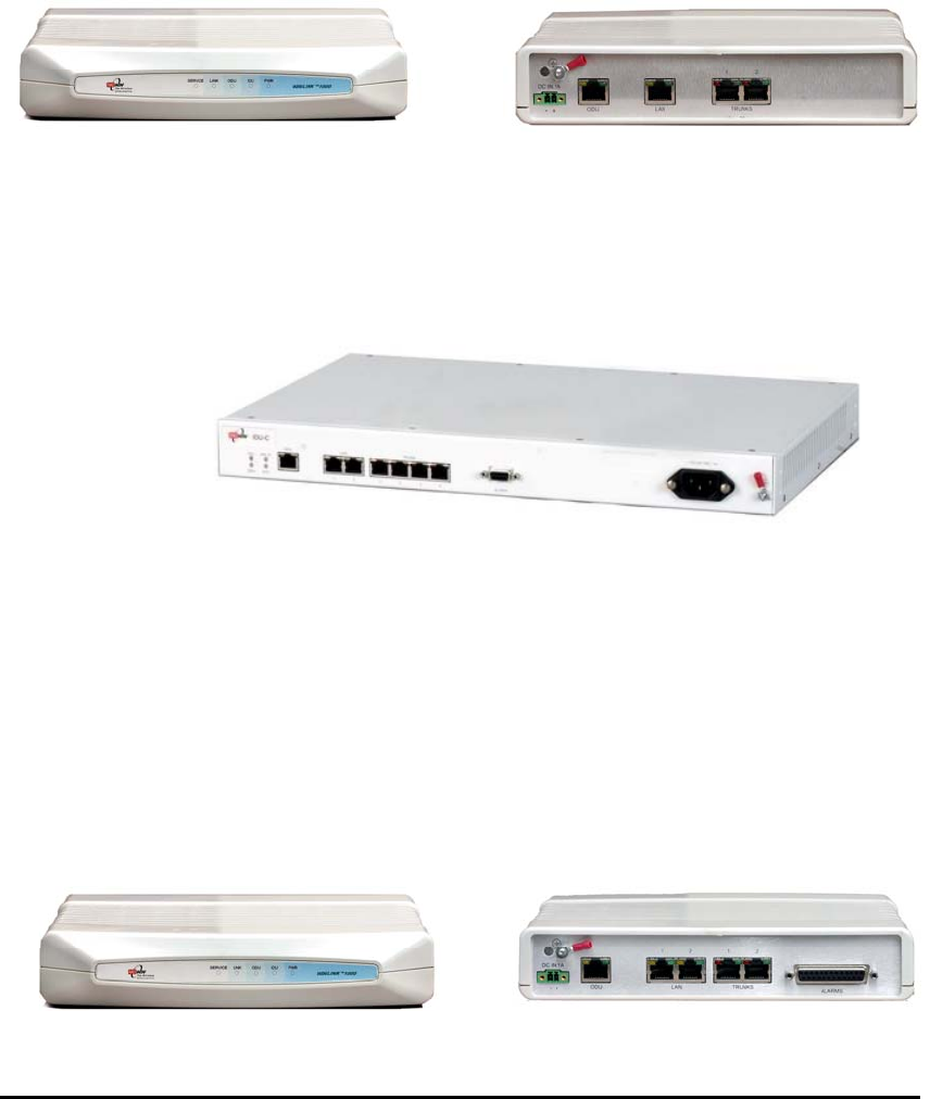
The Indoor Unit (IDU)
The IDU provides TDM and Ethernet ports to connect to the link. It
also provides power to the ODU. The IDU is available in four
configurations:
IDU-E
A compact, half 19 inch wide, 1U plastic unit, providing up to two
Ethernet ports and up to two E1/T1 interfaces.
Figure 2-2: IDU-E Front Panel
Figure 2-3: IDU-E Back Panel
IDU-C
A 19 inch, 1U metal unit, providing two Ethernet ports, 4xE1/T1
interfaces, and dry contact connector alarm.
Figure 2-4: IDU-C Front Panel
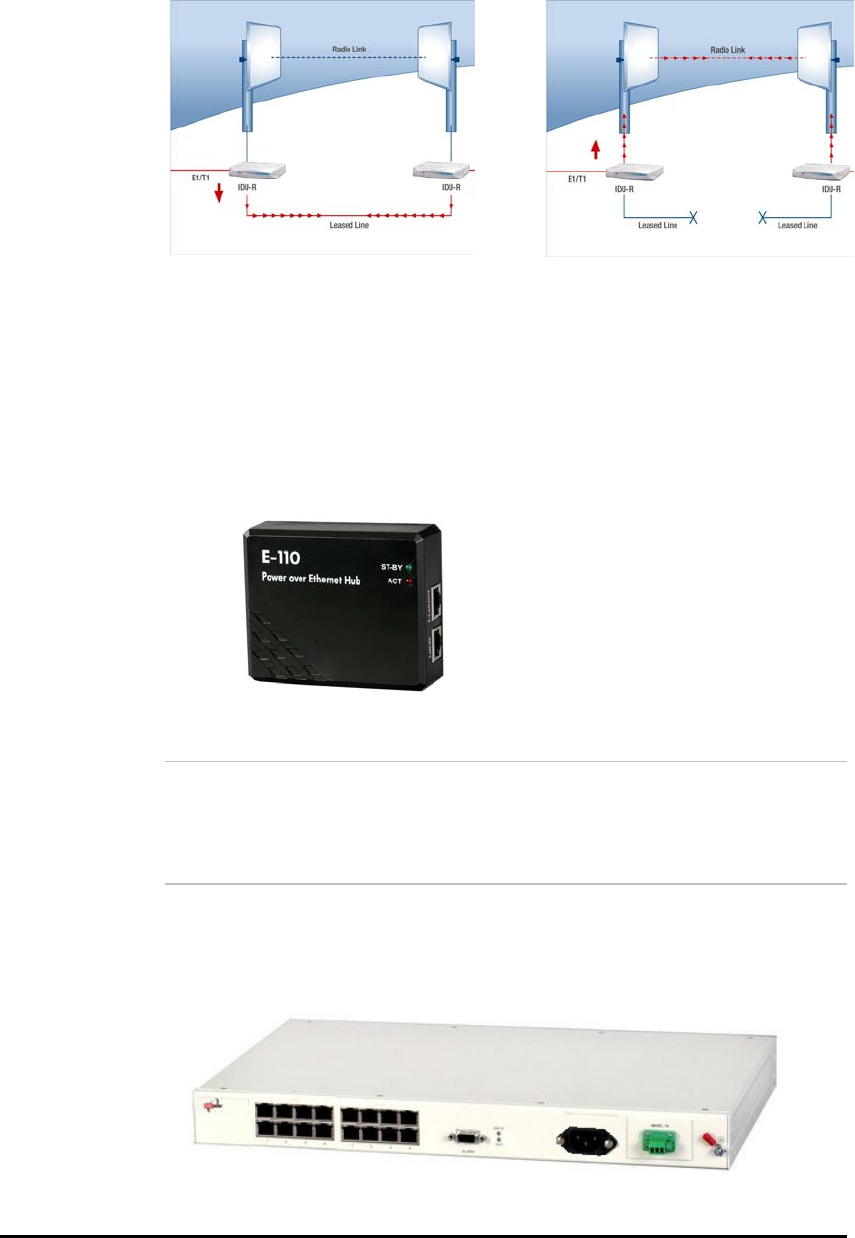
IDU-R
A compact, half 19 inch, 1U plastic unit for 1 x T1/E1 backup, providing
in addition 2 Ethernet ports and an external alarms interface. IDU-R is
an indoor unit used for automatic backup of leased lines. IDU-R
monitors the status of leased lines, and in the event of a connection
failure automatically switches to the radio link. The user configures
which of the two links is the main link and which is the backup link.
IDU-R operates with all WinLink™ 1000 outdoor units.
Figure 2-5: IDU-R Front Panel
Figure 2-6: IDU-R Back Panel
WinLink User and Installation Guide Version 1.795 2-9
Figure 2-7: Backup link for E1/T1 connections
Power Over Ethernet Units
Power over Ethernet units provide Ethernet services only.
Power over Ethernet (PoE)
An extremely compact device, the Power Over Ethernet (PoE)
provides Ethernet only services through one Ethernet port.
Figure 2-8: PoE
1.
Note:
The PoE can only be connected to ODU’s that are PoE enabled, or that
are High End or Access ODU’s.
PoE8
A 19 inch, 1U metal unit providing 8 Ethernet ports enabling
connection to collocated Ethernet applications.
Figure 2-9 PoE8

WinLink User and Installation Guide Version 1.795 2-10
O-PoE
Similar to the PoE, with weatherproof casing and sealed
connectors that enables outdoor connectivity (a special
mounting kit is supplied for attachment to a mast).
Figure 2-10: O-PoE Unit
The Outdoor Unit (ODU)
The ODU is the radio transceiver of the WinLink system and is the
main component of the system. The ODU connects to an antenna that
enables radio communication and can be mounted on a pole or wall.
The ODU connects to the IDU via a CAT5e cable.
ODUs are available in different frequencies and regulations in the
ranges: 2.3-2.7GHz, 4.9-5.95GHz.
The ODU comes in two different form factors depending on the type of
antenna:
• ODU with integrated 1ft flat panel antenna. This unit
contains both the ODU and antenna as a single unit housed in a
weatherproof casing.
• ODU with a connector for an external antenna. The unit
is fitted with an N-type connector. An external antenna can
extend the range of the link, and in some cases, may help to
reduce environmental interferences.
Various external antennas are available for the WinLink™ 1000
operating frequencies.
Figure 2-11: ODU with integrated antenna

WinLink User and Installation Guide Version 1.795 2-11
Figure 2-12: Typically used External Antennas
There are three series of ODU:
• WinLink™ 1000 Access
• WinLink™ 1000
• WinLink™ 1000 High End
The following table shows the differences between the systems:
Table 2-1:ODU Series Typical Characteristics
WinLink™ 1000 Access WinLink™ 1000 WinLink™ 1000 High End
Max Ethernet
Throughput
2Mbps 18Mbps 18Mbps
Max. Range 20Km 80Km 80Km
Supported
IDU devices
PoE PoE and IDU PoE and IDU
Services Ethernet Ethernet and TDM Ethernet and TDM
HSS + - +
Tx PW 18 dBm 18 dBm 23 dBm
WinLink User and Installation Guide Version 1.795 2-12
WinLink™ 1000 Manager
The WinLink™ 1000 Manager is an SNMP based element and link
management application which manages a complete link via a single IP
address. It identifies the IP Address, Subnet Mask, and Trap
Destination for each Site and also monitors the Radio Interface – RSS
[dBm] and Ethernet Service – Rx Rate and Tx Rate. The Manager
software facilitates the Link installation and Link configuration between
the ODU units. The intuitive, easy-to-use Manager has a graphical MS-
Windows interface, and can be utilized locally and remotely.
WinLink™ 1000 Manager provides:
• Planning tools such as a
Link Budget calculator
for calculating
the expected performance of the WinLink wireless link and the
possible configurations for a specific link range.
• Installation Wizard
• On-line monitoring of air interface quality allowing the
administrator to monitor the service and status of each link.
• On-line monitoring of equipment alarms and QoS
• Local and remote loopback testing
• Configuration settings
• On-line user manual and help files
• Over-the-air software upgrades
The WinLink™ 1000 Manager can easily be integrated with any NMS system.
Figure 2-13: WinLink™ 1000 Manager screen
WinLink User and Installation Guide Version 1.795 2-13
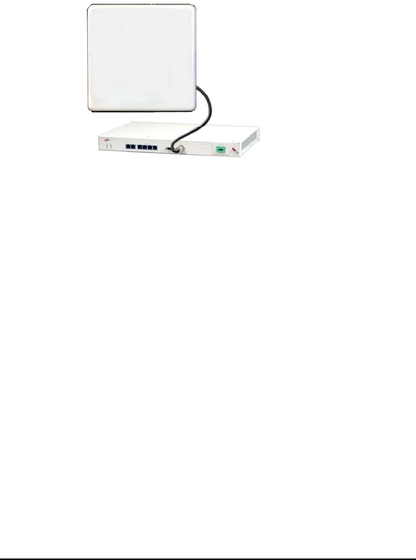
(All Indoor Unit) AIND
The AIND - All Indoor unit offers a single enclosure for Radio and
Multiplexer modules. It enables outdoor placement of only a passive
element.
Figure 2-14: AIND - "All Indoor" unit connected to antenna

WinLink User and Installation Guide Version 1.795 2-14
Technical Specifications
Air Interface
WinLink is available in several different frequency band ranges that
comply with ETSI, FCC and IC regulations.
Frequency Bands and Channel Bandwidth
Table
2-2: Configurable Transmission Options
Frequency Bands Max Transmit Power
(Configurable)
Max Antenna Gain
5.740-5.835 GHz 30 dBm 32 dBi
5.470-5.725 GHz 4 dBm 22 dBi
5.250-5.350 GHz 3 dBm 22 dBi
2.499-2.687 GHz 24 dBm 22 dBi
2.513-2.679 GHz 24 dBm 17 dBi
2.412-2.462 GHz 27 dBm 15 dBi
Channel Bandwidth 5MHz, 10MHz and 20MHz (5MHz Resolution)
Duplex Technique TDD (Time Division Duplex)
Sensitivity (dBm) @BER <10e-11
(20MHz)
-87 -84 -80 -79 -73 -66 -62
Rate (Mbps) 9 12 18 24 36 48 54
Modulation@OFDM (Adaptive) BPSK QPSK 16QAM 64QAM
Rates and Services Supported
WinLink systems offer a variety of channel bandwidths, maximum
throughput and supported services.
Table
2-3: Rates and Services Supported
Channel
Bandwidth
5 MHz 10 MHz 20 MHz
Maximum
Throughput
5.4 Mbps 9.9 Mbps 18 Mbps
Supported
Services
1 E1/T1 +
Ethernet
2E1s or 4T1s
+ Ethernet
4 E1/T1 +
Ethernet
Ethernet
Latency
8 msec 6 msec 3 msec

WinLink User and Installation Guide Version 1.795 2-15
NOTE
Before each installation you must use the Link Budget Calculator (
Link Budget Calculator) to locate the supported rates and services for
your particular product.
Regulations
WinLink operation complies with the radio and environmental
regulations listed in the following tables:
Table
2-4: Radio Regulations
FCC 47CFR part 15 subparts B&C and E, part 27 and part 90
IC RSS-210
ETSI EN 300 328 and EN 301 893
UK VNS 2107
Australia AS/NZS 4771
India WPC
Table
2-5: Environmental Regulations
Safety EN 60950, IEC 60950, UL 60950, CAN-CSA C22.2 60950
EMC EN 300 386, EN 301 489, EN 55022, EN 61000, EN 55024,
AS/NZS CISPR 22, CAN/CSA-CEI/IEC CISPR 22-02, FCC
47CFR class B part 15 sub-part B
Environmental IEC 60721 class 4M5 IP67
Ethernet Services
The WinLink LAN port provides 10/100BaseT interfaces with auto-
negotiation and transparent VLAN support. Traffic handling is provided
by a MAC level self-learning bridge. Ethernet services include:
• 1 or 2 Ethernet interfaces in the indoor units
• 10/100BaseT with auto-negotiation (IEEE 802.3)
• Layer 2 Ethernet bridge
• Self-learning of up to 2047 MAC addresses (IEEE 802.1Q)
• Support of 1+1 applications (HUB/Bridge selectable mode)
• Up to 18 Mbps symmetrical net throughput
• VLAN transparent
• Latency < 3msec

WinLink User and Installation Guide Version 1.795 2-16
• Retry mechanism for loss-less connection (Fast ARQ)
TDM (E1/T1) Services
The WinLink TDM interface accepts E1 or T1 traffic, supporting
unframed operation (E1 and T1) and AMI and B8ZS zero suppression
(T1). TDM services include:
• 1 to 4 E1/T1 interfaces in the indoor units
• Standard E1/T1, compliant with ITU-T standards
• Unframed E1/T1
• BER < 1 x 10-11 @ sensitivity threshold
• Accurate clock recovery mechanism (<50 PPB)
• One way delay < 8msec
• Advanced clock configurations

WinLink User and Installation Guide Version 1.795 2-17
Technical Specification Summary
Table
2-6: Technical Specification Summary
Air Interface
Technology
OFDM
Duplexing Method
Time Division Duplex (TDD)
Capacity
Configurable up to 54 Mbps
Modulation
OFDM - BPSK, QPSK, 16QAM, 64QAM
Channel Resolution
5/10/20 MHz (ETSI systems do not support 5/10)
(BRS systems Single and Double only)
Transmitter Power
Specification is different per product, for further
details refer to the
Link Budget Calculator
Range
Up to 41 km (25.5 miles)
Up to 80 km (50 miles) with an external antenna
ACCESS versions up to 20 km.
Frequency Bands [GHz]
2.3-2.7GHz, 4.9-6GHz.
Antennas (See Antenna Characteristics in
Antenna)
LAN Interface
PHY
Up to 2 × 10/100BaseT, auto-sensing
Framing/Coding
IEEE 802.3/U
Bridging
Self-learning, up to 2048 MAC addresses
Line Impedance
100Ω
VLAN Support
Transparent
Frame Size
1536 bytes max for IDU
1800 bytes max for POE
Connector
RJ-45
E1 Interface
Data Rate
Unframed (transparent) 2.048 Mbps
Line Code
HDB3
Connector
RJ-45
No. of Ports
IDU-E: 1 or 2
IDU-C: 4
T1 Interface
Data Rate
Unframed (transparent) 1.544 Mbps
Line Code
AMI, B8ZS
Connector
RJ-45
No. Of Ports
IDU-E: 1 or 2
IDU-C: 4

WinLink User and Installation Guide Version 1.795 2-18
Air Interface
Technology
OFDM
Indicators
PWR (green)
Power status (IDU-E only)
IDU (green)
IDU-C status
ODU (green/red)
ODU-to-IDU link status
LINK (green/red)
Link status
SERVICE (green/red)
E1/T1 signal status
Power
Source
IDU-E: 100–240 VAC via external AC/DC converter
IDU-C: 100–240 VAC via AC cable
-20 to –60 VDC
O-PoE: 100–240 VAC via attached (pigtail) AC cable
PoE-8: 100–240 VAC via AC cable
-20 to –60 VDC Max
Note: Both AC and DC power sources can be
connected simultaneously but only one source will supply
the power
Power Received by
the ODU
-42 to -60 VDC
Power Consumption
ODU plus IDU-E or IDU-E-AL or IDU-R – 10W max
ODU plus IDU-C – 14W max
AIND – 14 max
O-PoE plus ODU – 25W max
PoE-8 plus 8 ODU units – 60W max
Connector
IDU-E 2-pin
IDU-C AC – 3-pin IEC connector
DC – 3-pin terminal block
Connector
DB-9 female for IDU-C/AIND/PoE-8
DB-25 female for IDU-E-AL/IDU-R
Alarm
Connector
Electrical Characteristics
Dry Contact, 30V/2A
Max input current, 0.01A at 0.5W (R=5K)
Sync Connector
Connector
RJ-11 for AIND
Physical
Outdoor Unit
ODU with integrated antenna
Height
24.5 cm / 9.3 in 30.5 cm / 12 in
Width
13.5 cm / 5.13 in 30.5 cm / 12 in
Depth
4.0 cm / 1.57 in 5.8 cm / 2.3 in
Weight
1.0 kg / 2.2 lb 1.5 kg / 3.3 lb

WinLink User and Installation Guide Version 1.795 2-19
Air Interface
Technology
OFDM
Indoor Unit
IDU-E IDU-C/AIND/PoE-8
Height
4.5 cm (1.7 in) 1U 4.5 cm (1.7 in) 1U
Width
23.5 cm (9.3 in) 29 cm (11.5 in)
Depth
16.5 cm (6.7 in) 43 cm (17.7 in)
Weight
0.5 kg (1.1 lb) 1.5 kg (3.3 lb)
Environment Outdoor Unit
Enclosure
All-weather case
Temperature
-35 to 60°C/-31 to 140°F
Indoor Unit (IDU-E, IDU-E-AL, IDU-R, and IDU-C)
Temperature
-0 to 50°C/32 to 122°F
Relative Humidity
Up to 90%, non-condensing
Indoor Unit (PoE-8)
Temperature
-0 to 45°C/32 to 113°F
Relative Humidity
Up to 90%, non-condensing
All Indoor Unit (AIND)
Enclosure IDU-C indoor unit
Temperature -35 to 60°C/-31 to 140°F

Chapter 3
Installation and Setup
This section describes the installation, alignment, and setup procedures
for a WinLink system.
Site Requirements and Prerequisites
For the IDU units, allow at least 90 cm (36 in) of frontal clearance for
operating and maintenance accessibility. Allow at least 10 cm (4 in)
clearance at the rear of the unit for signal lines and interface cables.
The ambient operating temperature should be –45 to 60°C/–49 to
140°F (ODU), or –5 to 45°C/23 to 113°F (IDU) at a relative humidity of
up to 90%, non-condensing.
Package Contents
The WinLink packages include the following items:
ODU package containing:
• ODU
• Mast/Wall mounting kit plus mounting instructions
• CD-ROM [WinLink™ 1000 Manager, Installation and Operation
Manual, and Link Budget Calculator]
• Self adhesive label showing the MAC address and the
alternative community string KEY. Keep this label safe.
• Spare RJ-45 connector
IDU-E or IDU-R package containing:
• IDU-E or IDU-R
• AC/DC Converter
• IDU wall-mounting drilling template
• Self adhesive label showing the IDU LED operation
• Spare RJ-45 connector
IDU-C Package containing:
• IDU-C

WinLink User and Installation Guide Version 1.795 3-21
• For AC model, 110/240 VAC with IEC 60320 socket cable
• For DC model, 3-prong terminal block connector (green)
• 19” mounting kit
• Spare RJ-45 connector
PoE-8 Package Containing:
• PoE-8
• 110/240 VAC with IEC 60320 socket cable
• 3-prong terminal block connector (green)
• 19” mounting kit
• Spare RJ-45 connector
External antenna (if ordered)
• 1m RF cable
• Mounting kit
• ODU/IDU cable at length ordered (optional)
O-PoE package contains:
• O-PoE
• Mast/Wall mounting kit plus mounting instructions
• Spare RJ-45 connector
Additional Equipment Required
The following is a list of the equipment required for installing the
WinLink hardware.
• RJ-45 crimp tool (if pre-assembled ODU/IDU cable is not used)
• Drill (for wall mounting only)
• IDU and ODU 10AWG grounding cables
• O-PoE 10AWG grounding cable
• 13 mm (½″) spanner/wrench
• ODU to IDU cable if not ordered (outdoor class, CAT-5e, 4
twisted pairs 24AWG)
• ODU to O-PoE both cables (ETH and PoE) if not ordered
(outdoor class, CAT-5e, 4 twisted pairs 24AWG)
• Cable ties
• Laptop running Windows 2000 or Windows XP.

WinLink User and Installation Guide Version 1.795 3-22
Installation Sequence
The following steps are required to install the WinLink system:
1. Install the management program on the network management
station/laptop. See Installing the WinLink Management Software,
page 3-24.
2. Mount the ODU at each site (and antenna if external antenna is
used). See Mounting the ODU, page 3-25.
3. Connect the ODU to the IDU at both sites. See page 3-27.
4. Connecting the Ground to the IDU, IDU-C, PoE-8, page 3-28.
5. Connect the power. See Connecting Power to an IDU, page 3-29,
and Connecting Power to an O-PoE, page 3-29
6. Align the ODU/antennas. See page 3-30.
7. Run the Installation wizard from the management program. See 3-
31.
8. Connect user equipment to the local and remote IDUs. See page 3-
35.
WinLink User and Installation Guide Version 1.795 3-23
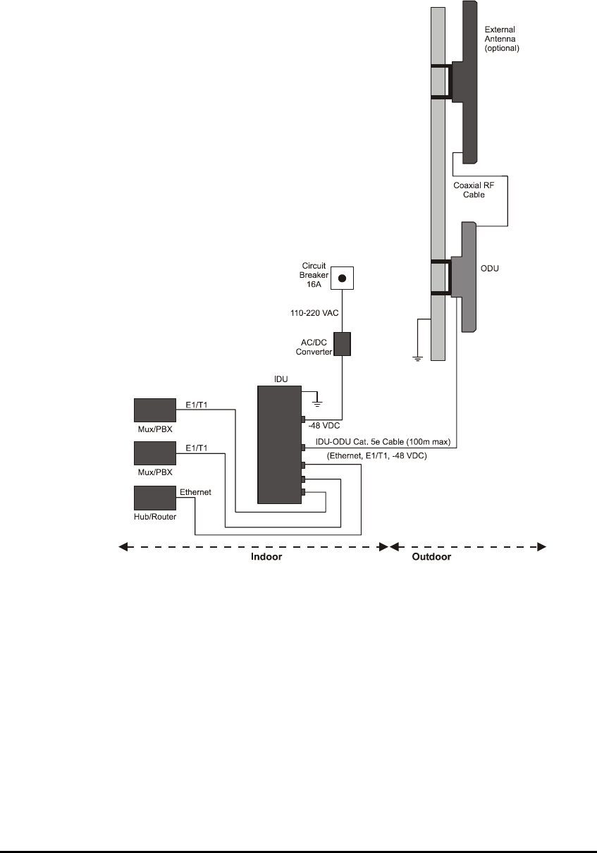
The following diagram illustrates a typical installation of WinLink™
1000 with an external antenna.
Figure 3-1: Typical Installation Diagram (with external antenna)
The installation steps are detailed in the following sections.

WinLink User and Installation Guide Version 1.795 3-24
Installing the WinLink Management Software
Minimum Requirements
The WinLink management application is distributed on CD-ROM as an
executable file. The application has the following PC requirements:
• Memory: 128 MB RAM
• Disk: 1 GB free hard disk space
• Processor: Pentium 3 or higher
• Network: 10/100BaseT NIC
• Graphics: Card and monitor that support 1024×768 screen
resolution with 16 bit color
• Operating system: Windows 2000/XP
• Microsoft Explorer 5.01 or later.
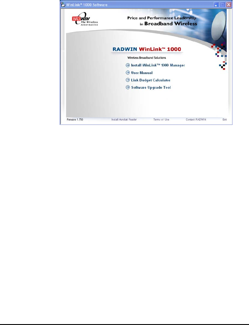
WinLink User and Installation Guide Version 1.795 3-25
Installing the Software
To install the WinLink management program:
1. Insert the CD-ROM into your CD-ROM drive.
The WinLink™ 1000 Installation screen appears:
2. Choose Install WinLink™ 1000 Manager and follow the on-screen
instructions of the installation wizard to complete setup of the
WinLink™ 1000 Management program in the desired location.
Any PC running the WinLink™ 1000 management application can be
used to configure WinLink™ 1000 units.
Mounting the ODU
The ODU is the transceiver element of the WinLink system. The ODU
can be mounted on a mast or a wall. In both installations, the supplied
mounting kit is used to secure the ODU.
Mast and Wall Installation describes the mast/wall installation
instructions.
A WinLink link operates in pairs of two ODUs with the same
configuration. Both ODUs must be installed, and the antennas aligned
for maximum throughput.

WinLink User and Installation Guide Version 1.795 3-26
Prior to connecting cables to the ODU, the protective earth terminal
(screw) of the ODU must be connected to an external protective
ground conductor or to a grounded mast. For grounding the O-PoE,
connect the grounding cable from the dedicated earth terminal (screw
at the side of the enclosure) to an external protective ground
conductor or to a grounded mast.
Only a qualified person using the proper safety equipment should climb
the antenna mast. Only trained professional installers should be used
when installing or dismantling ODUs and masts.
To mount the ODU:
1. Verify that the ODU mounting brackets are properly grounded.
2. Mount the ODU onto the mast or wall. Ensure that the unit is
oriented so that the cable connectors are at the bottom. (If they
are on top, water may penetrate into the unit causing
damage.) Refer to
Mast and Wall Installation for the ODU or O-PoE mounting
instructions.
3. Connect the ground cable to the chassis point on the ODU.
4. Attach the ODU-IDU cable to the ODU RJ-45 connector. If making
own ODU-IDU cable, refer to
Wiring Specifications for the connector pin-out.
5. Screw in the cable glands to ensure hermetic sealing of the ODU.
6. Secure the cable to the mast or brackets using UV-rated cable ties.
7. Repeat the procedure at the remote site.
2.
Note:
Do not tightly secure the ODU to its mounting brackets until the
alignment process of the antenna is complete.
When installing the ODU, check that there are no direct obstructions in
front of the ODU or interference from man-made obstacles.
For O-PoE UL Listed parts and components must be used for
installation. Use UL listed devices having an environmental rating equal
to or better than the enclosure rating to close all unfilled openings.
Warnin
g
Cautio
n
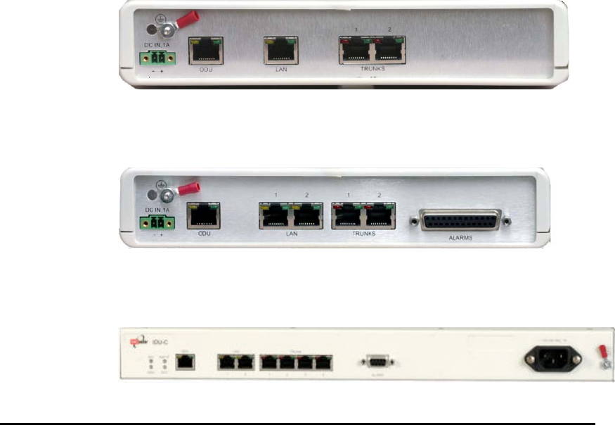
WinLink User and Installation Guide Version 1.795 3-27
Connecting the ODU to the IDU
The ODU-IDU cable conducts all the user traffic between the IDU and
the ODU. The ODU-IDU cable also provides -48 VDC supply and
Ethernet to the ODU. The maximum length for one leg of the ODU-IDU
cable is 100m (328 ft) in accordance with 10/100BaseT standards.
When using an O-PoE or PoE-8, the maximum length for two legs of
the O-PoE or PoE-8 cable is 100m (328 ft) in accordance with
10/100BaseT standards.
The ODU-IDU cable is supplied pre-assembled with RJ-45 connectors,
at the length specified when ordering. If the ODU-IDU cable was not
ordered, use Cat. 5e 24AWG shielded cable. Wiring specifications are
given in
Wiring Specifications.
To connect the ODU to the IDU
1. Route the cable from the ODU to the IDU.
2. Secure the cable along its path.
3. Connect the ODU-IDU cable to the RJ-45 connector on the IDU.
The figures below illustrate typical IDU panels. You may have
differences in your panels depending on the hardware ordered.
Figure 3-2: Typical IDU-E Rear Panel
Figure 3-3: IDU-R Rear Panel
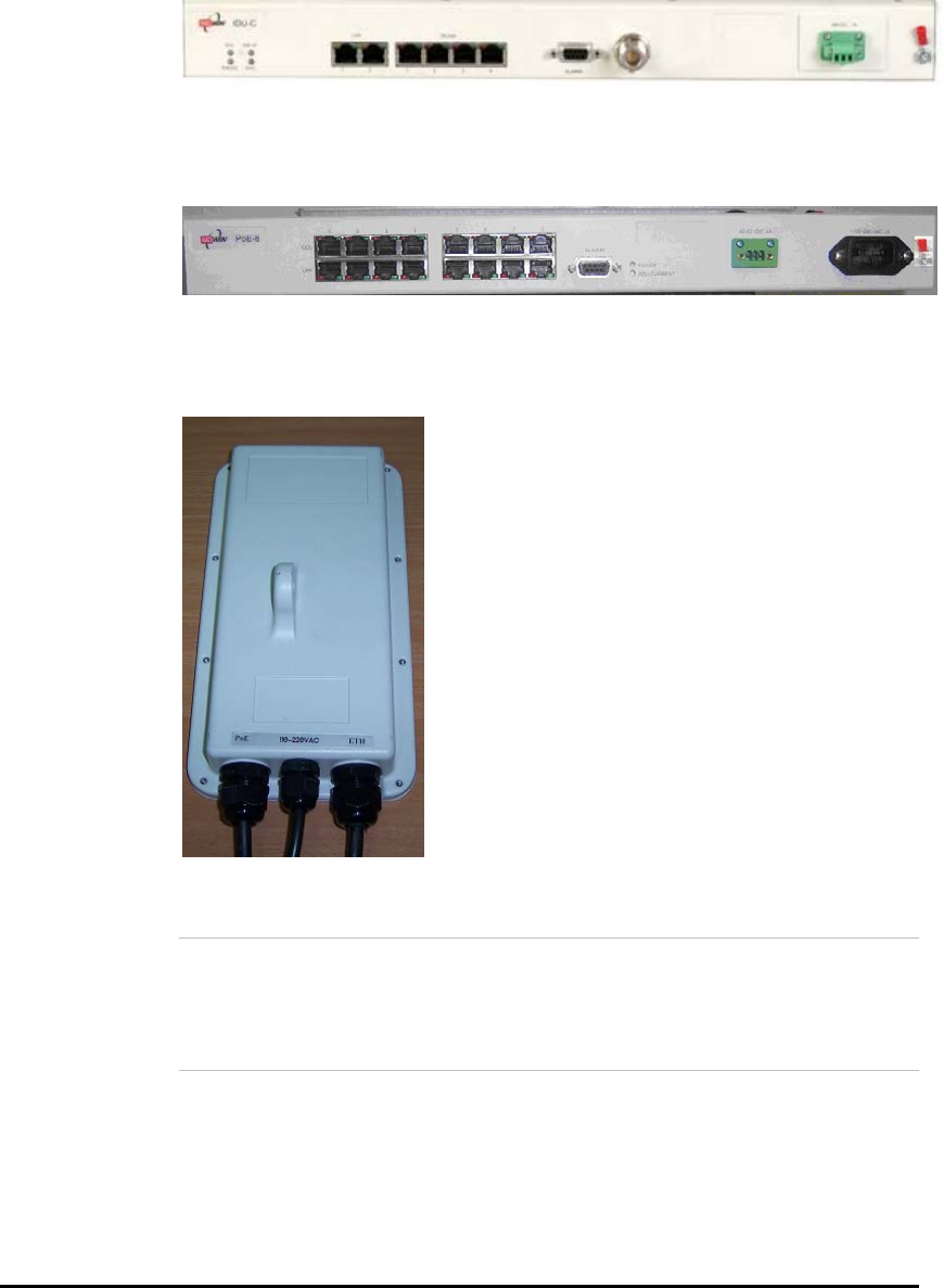
WinLink User and Installation Guide Version 1.795 3-28
Figure 3-4: Typical IDU-C Front Panel
Figure 3-5: AIND All Indoor Radio Unit
Figure 3-6: PoE-8 Unit
Figure 3-7: O-PoE Unit
3.
Note:
Panels may be fitted with different connector combinations than
shown, depending on the model ordered.
IDU-R Installation
Installation of an IDU-R unit differs from other IDU models in one
respect: At the rear of the IDU-R (see Figure 2-6 above) there are two
jacks labeled “Trunks”. For each IDU-R, the E1 cable from outside
should be plugged into one of the trunks, and the E1 cable to the other

WinLink User and Installation Guide Version 1.795 3-29
station should be plugged into the second trunk, as in the left hand
side of Figure 2-7 above.
Apart from the above difference, the link installation including the
remaining part of the IDU installation and connection to the ODU
proceeds as described as above.
Connecting the Ground to the IDU
Connect an 18AWG grounding cable to the grounding terminal of the
device. The device should be permanently connected to the ground.
Connecting Power to an IDU
AC power is supplied to the WinLink™ 1000 IDU through a standard
IEC 60320 connector.
AC power should be supplied via a 1.5m (5 ft) standard power cable
terminated by a IEC 60320 socket. A cable is provided with the unit.
To connect AC power to an IDU:
Connect the power cable socket to the power connector on the
WinLink front panel.
• Connect the power cable plug to the mains outlet.
The unit turns on automatically upon connection to the mains.
To connect DC power to an IDU
A special 3-prong socket for DC power connection is supplied with the
unit.
Connecting Power to an O-PoE
AC power is supplied to the O-PoE via a 3m (10 ft) 3 wire AC cable
attached to the unit (pigtail). The AC cable is provided with no
termination.
To connect AC power to an O-PoE:
Connect the power cable to a protected/shielded AC mains outlet.
The AC mains outlet should be provided with circuit breaker rated 5A
according to the local national electrical code.
The unit will be turned on automatically upon connection to the mains.
To maintain Overvoltage (Installation) Category II, install a suitable
surge suppressor device in the branch circuit to limit expected
transients to Overvoltage Category II values.
The limits are based on IEC60664 and are also located in Table 2H of
UL60950 (for mains ≤ 150V, the transient rating is 1500V;
Warning

WinLink User and Installation Guide Version 1.795 3-30
for 150V < mains ≤ 300V, the transient rating is 2500V;
for 300V < mains ≤ 600V, the transient rating is 4000V).
Aligning Antennas with the Beeper
Perform the antenna alignment using the ODU’s audible tone. The tone
is not suitable for aligning the All Indoor Units (AIND). To align an
AIND system, see
AIND Alignment.
To speed up the installation time, alignment of a WinLink™ 1000
system should be performed by two teams simultaneously, at site
A and at site B.
Æ To align the ODUs using the alignment tone:
1. Verify that power is connected to the IDUs at both sites.
Do not stand in front of a live ODU.
Provided that Site A detects the signal from Site B, the ODU starts
beeping 20 seconds after power up, and continues beeping until
the ODUs are aligned, and the installation is complete.
2. Verify normal operation of the IDU by the LED indications on the
front panel. See IDU Front Panel Indicators.
3. Direct the antenna of site B in the direction of the site A. This is
simplified if a previous site survey has been completed and
azimuths are known.
4. Make an azimuth sweep of 180 degrees with the site A ODU so that
the strongest signal from site B can be detected.
5. Slowly turning the site A ODU back towards the position of Site B,
listen to the tone until the best signal is reached. See the following
figure for audible signal variations.
Warning

WinLink User and Installation Guide Version 1.795 3-31
Figure 3-8: Beeper Sequence for ODU Alignment
Note:
Three beeps and a pause is the best signal
Two beeps and a pause, signal quality increased
One beep and pause is no signal change
Any other signal detects no signal between ODUs.
6. Secure the site A ODU to the mast/wall.
7. At site B, adjust the ODU slowly whilst listening to the beeper
sequence until the best signal is attained.
8. Secure the site B ODU to the mast/wall.
9. Monitor the link quality for about 15 minutes to verify stability.
Installing the Link
During the installation procedure, the definition of all parameters is
automatically applied to both sides of the link.
Note:
For HSS screens see
Hub Site Synchronization..
Æ To install the link:
1. Verify that there is IP connectivity between the management
station/laptop and the IDU, and that the WinLink™ 1000 Manager
application is running.
2. With BRS systems you need to activate the link at both sites, see
BRS Installation Procedure
for method. Once the link is activated,
continue installation from this point.
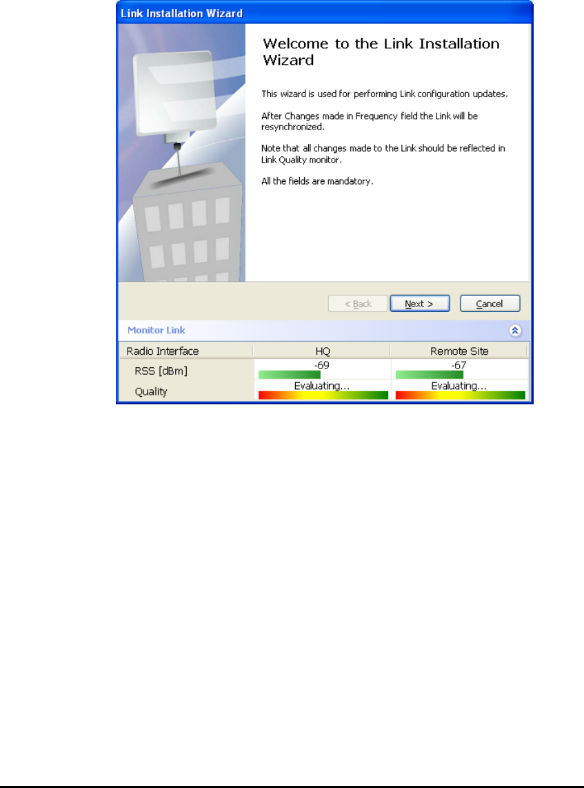
WinLink User and Installation Guide Version 1.795 3-32
3. In the toolbar, click the Link Installation button. The Link
Installation button is only accessible if antennas are aligned. Align
antennas if this box is “grayed out”.
The Installation wizard opens:
Figure 3-9: Link Installation Wizard
4. Click Next to proceed with the installation procedure.
The system dialog box opens:
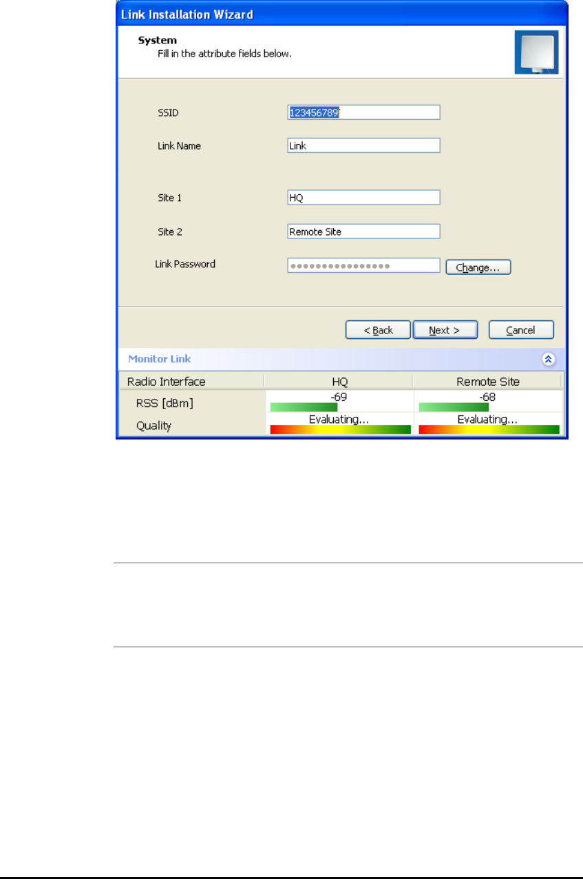
WinLink User and Installation Guide Version 1.795 3-33
Figure 3-10: Installation Wizard, System dialog box
5. Enter a SSID (System ID – must unique for each link in the area).
The SSID must include at least eight alphanumeric characters. Up
to 24 characters are allowed.
4.
Note:
Both sides of a link must have the same SSID number for data
transmission to take place.
6. Enter a Link Name for the link identification.
7. Enter a name for site 1 (the site to which your laptop is
connected).
8. Enter a name for site 2 (remote site).
9. Optionally enter a new Link Password (version 1.400 and after).
See Changing the Link Password, page 7-115 for details on the Link
Password.
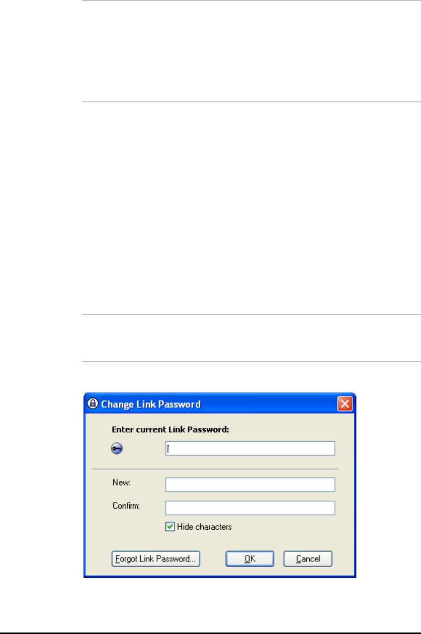
WinLink User and Installation Guide Version 1.795 3-34
5.
Note:
If the Link Password is incorrect a link is established but configuration
cannot be performed and no services are available. A new link
password may be obtained from Technical Support or use the
alternative password supplied with the product.
See
Changing the Link
Password
for more details.
10. Click Next.
The default link with a rate of 9 Mbps is evaluated.
The
Channel Setting
dialog box appears. This dialog box may be
different according to the version that you have purchased.
Changing the Link Password
The default password is Wireless-Bridge. Optionally, you can change
the link password as explained here.
Æ To change the Link password:
1. Click the Change button in the System dialog box.
The Change Link Password dialog box opens.
Note:
Use the Hide Characters check box for maximum security.
Figure 3-11: Change Link Password dialog box
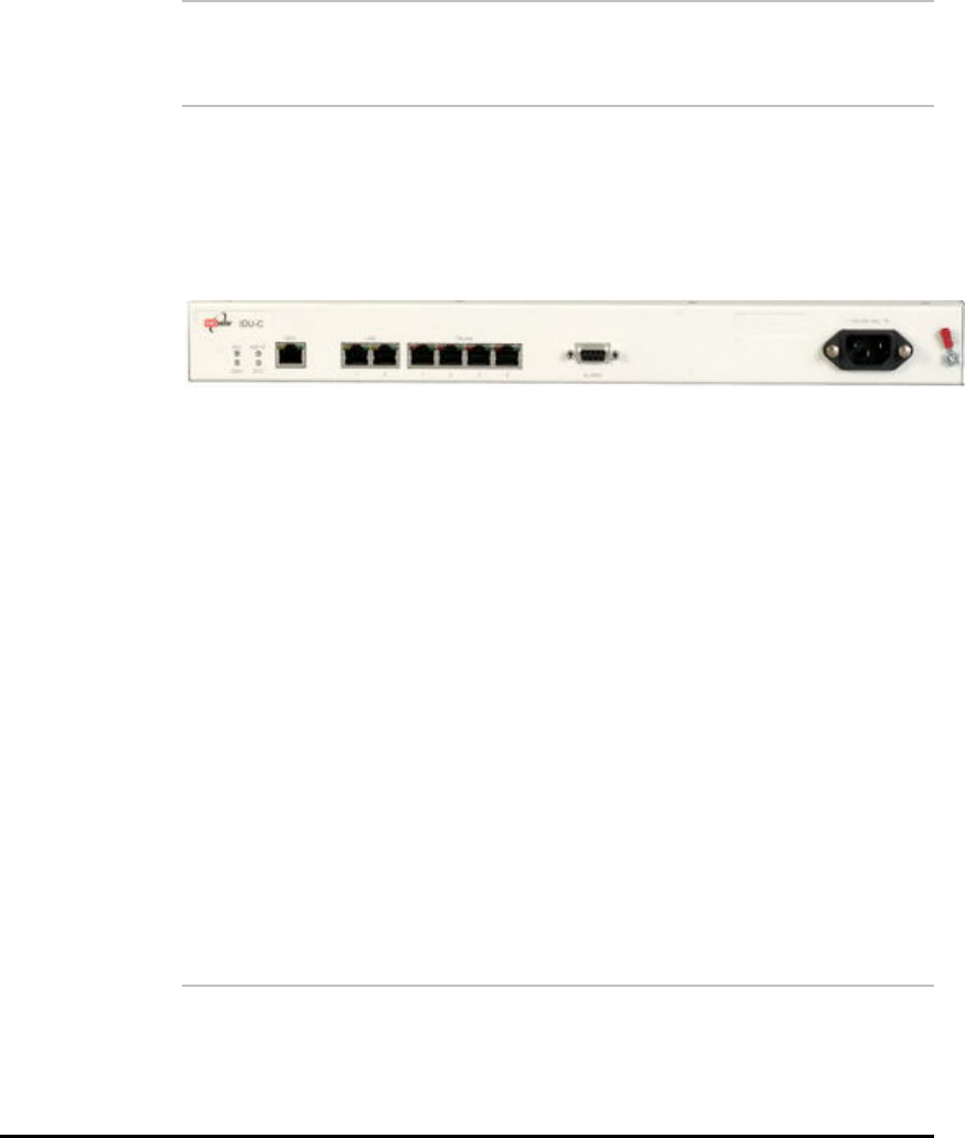
WinLink User and Installation Guide Version 1.795 3-35
2. Enter the default link password wireless-bridge.
3. Enter a new password.
4. Retype the new password in the confirm field.
5. Click OK.
6. Click Yes when asked if you want to change the link password.
7. Click OK at the successful message.
Note:
Restoring Factory Defaults returns the Link Password to wireless-bridge.
Re
Connecting the User Equipment
The IDU is a standalone desktop, wall-mounted, or rack-installed unit.
The following figure illustrates a typical front panel of the IDU:
Figure 3-12: Typical Front Panel of IDU-C
Æ To connect user equipment to the IDU:
1. Connect user E1/T1 traffic to the IDU panel RJ-45 port designated
TRUNK. There may be multiple Trunk ports available depending
on unit ordered.
Refer to
Wiring Specifications, for the connector pinout.
2. Connect user hub/router or any other compatible device to the IDU
panel RJ-45 port designated LAN. There may be multiple LAN ports
available for connecting to different LANs depending on the IDU
unit ordered.
Refer to
Wiring Specifications for the connector pinout.
Note:
Use a straight cable for router connection.
Do not connect two LAN ports to the same LAN, or flooding may occur.
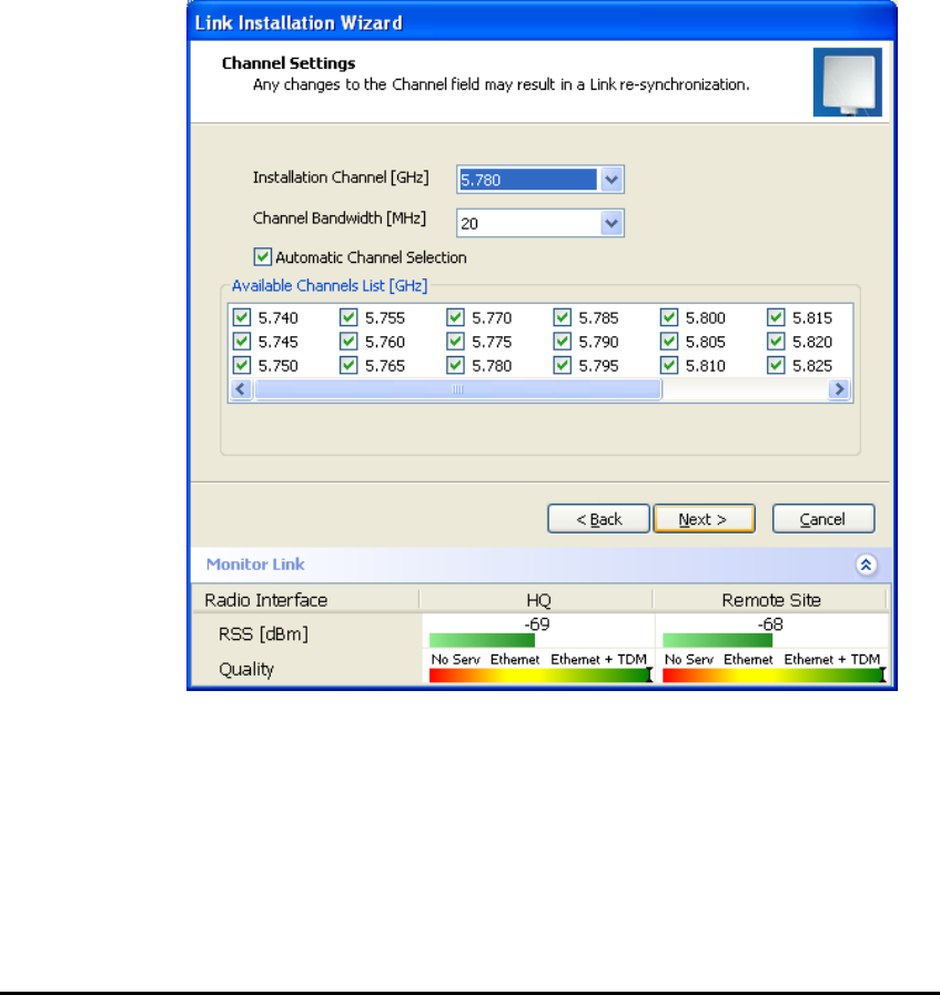
WinLink User and Installation Guide Version 1.795 3-36
Selecting Channels
WinLink systems later than version 1.300 have a feature called
Automatic Channel Select, which allows you to define several
alternative frequency channels if interference is detected on the
channel in use.
Note: For the ETSI version, skip to page 3-37; for the BRS version,
skip to page 3-38.
WinLink™ 1000 with Automatic Channel Select
Automatic Channel Select (ACS) gives WinLink the ability to change
frequency channels automatically if interference is detected on the
current operating channel.
Figure 3-13: Channel Select dialog box - Automatic Channel Select
1. Select the main frequency from the Installation Channel menu.
2. Select the required Channel Bandwidth 5, 10, or 20 MHz. Default is
20 MHz.
When changing the channel bandwidth, the WinLink Manager
repeats evaluation of the link.

WinLink User and Installation Guide Version 1.795 3-37
3. Click the check box if Automatic Channel Selection is required.
4. Click the check boxes in the Available Channels List of all the
allowable channels that can be automatically selected.
Selecting a new channel causes the system quality to change. The
quality bar shows the adjustment until the system finds the best
quality link.
Quality Service
0.1% – 0.4% 80-99% TDM + Ethernet
0.4% – 2.0% 77- 56% Ethernet
2.0% – 50.0% 44 - 2% Antenna Alignment or replace
Channel
5. If you are not satisfied with the channel that is selected
automatically, click Reselect Channel.
A new channel is selected from one of the Available Channels that
has been defined.
6. Click Next.
The Evaluating Rate box appears. When the optimum rate for the
link is selected the Service Parameters dialog box opens. Skip to
page 3-40 to set the Service parameters.
Note:
Any changes to the frequency settings cause the link to re-synchronize.
A short loss of service will occur during re-synchronization.
WinLink 5.4 GHz ETSI Version
In accordance with ETSI, if WinLink detects Radar interference it
changes the frequency channel automatically. This feature is termed
Dynamic Frequency Selection (DFS). In this version, the Automatic
Channel Selection is selected by default and a minimum of two
channels must be defined as available.
1. Select the main frequency from the Operating Channel menu.
2. Select the Bandwidth required.
6.
Note:
Automatic Channel Selection is selected by default.

WinLink User and Installation Guide Version 1.795 3-38
3. Click at least two check boxes in the Available Channels List of all
the allowable channels that can be automatically selected.
7.
Note:
Installation will not continue until at least two channels are defined.
Selecting a new channel causes the system quality to change. The
quality bar shows the adjustment until the system finds the best
quality link.
Any channel selected is evaluated for 60 seconds; therefore this
selection process may take a few minutes.
4. If you are not satisfied with the channel that is selected
automatically, click Reselect Channel.
A new channel will be selected from one of the Available Channels
that has been defined.
5. Click Next.
The Evaluating Rate box appears. The optimum rate for the link is
selected.
The Service Parameters dialog box opens. Proceed to page 3-40.
WinLink™ BRS Version
Note:
Both sites in a BRS Link must be configured identically.
Æ To Configure BRS Channel Settings
1. Set the Band Plan.
2. Select the Bandwidth required,
Single Band (5 MHz)
Double Band (10 MHz)
Quad Band (20MHz)
3. Select the Frequency from the pull-down menu.
4. Click Next. The system is re-synchronized to the changes.
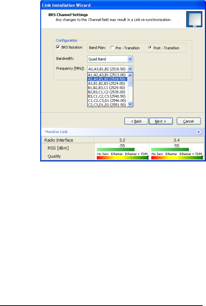
WinLink User and Installation Guide Version 1.795 3-39
Figure 3-14: BRS Channel Settings Post-Transition
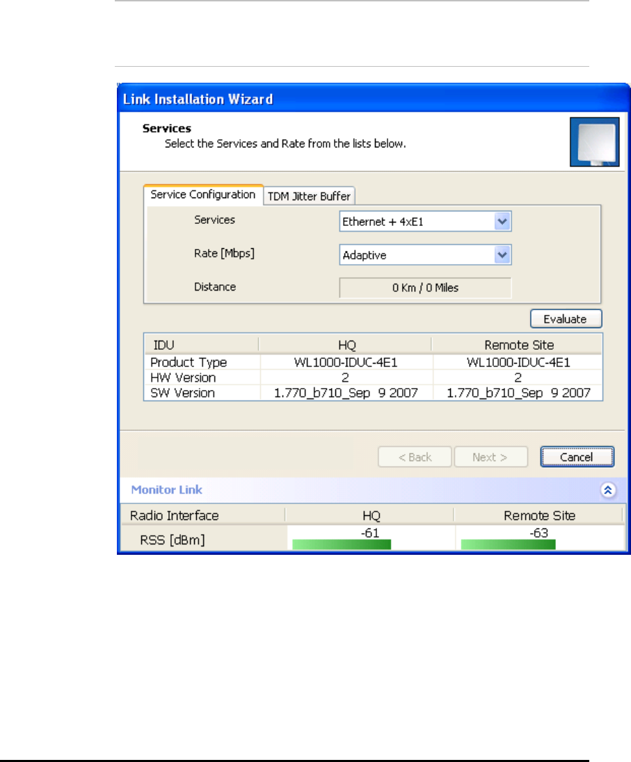
WinLink User and Installation Guide Version 1.795 3-40
Selecting the Service Parameters
You define the type of service required, Ethernet Only or Ethernet with
TDM in the Services screen as shown below. Notice that the Distance
between the sites automatically appears in the Distance box (from
Version 1.600).
Note:
WinLink ACCESS versions are Ethernet Only.
Figure 3-15: Installation Wizard, Service dialog box
Æ To select the services and rates:
1. In the Services box, select a service:
• Ethernet Only
• Ethernet + E1/T1.
The available bandwidth depends on the number of E1/T1 ports
selected.

WinLink User and Installation Guide Version 1.795 3-41
2. In the Rate box, select the required transmission rate.
If Adaptive is selected (refer to page 1-5 for information about
Automatic Adaptive Rate), WinLink constantly monitors and
adjusts the transmission rate to ensure maximum throughput for
the link at the highest quality. ACCESS versions are preset to
adaptive and the rate selection is disabled.
3. Click the Evaluate button. The optimum transmission rate for the
selected services is evaluated. Table 3-1: Rates per Bandwidth
shows the rates used by WinLink.
4. Click Next.
If TDM services were selected, then the TDM parameters dialog box
appears, (see
Figure
3-16: TDM Parameters dialog box
).
Note:
ACCESS versions do not have TDM services. Instead, ACCESS versions
operate at a default rate of 2 Mbps.
If Ethernet Only was selected, then the Finish screen appears
(see
Figure
3-19: Installation Wizard, Finish Screen
) showing a
summary of the link configuration, the alignment is complete.
Table
3-1: Rates per Bandwidth
Modulation/FEC 5 MHz 10 MHz 20 MHz
BPSK / ¾ 2.25 Mbps 4.5 Mbps 9 Mbps
QPSK / ½ 3 Mbps 6 Mbps 12 Mbps
QPSK / ¾ 4.5 Mbps 9 Mbps 18 Mbps
16QAM / ½ 6 Mbps 12 Mbps 24 Mbps
16QAM / ¾ 9 Mbps 18 Mbps 36 Mbps
64QAM / 2/3 12 Mbps 24 Mbps 48 Mbps
64QAM / ¾ 13.5 Mbps 27 Mbps
Setting the Clock Configuration
If TDM services are selected then the TDM parameters dialog box
appears. (TDM is not relevant in WinLink ACCESS versions.)
The TDM Parameters dialog box contains five working modes; select
the appropriate clock mode according to your application. Choosing
one of these modes sets the TDM clock behavior on both sides of the

WinLink User and Installation Guide Version 1.795 3-42
link. The user equipment must be configured as described in the
following table.
Table
3-2: TDM Clock Modes
Unit Clock Mode User Equipment Side
Local Unit Remote Unit HQ side Branch side
1 Transparent Transparent Internal/Recover Internal/Recover
2 Loop Time Recover Internal Recover
3 Recover Loop Time Recover Internal
4 Internal Recover Recover Recover
5 Recover Internal Recover Recover
Transparent/Transparent
WinLink transparently regenerates the clock from line clock
side to Tx clock on the opposite side of the link.
Loop time/Recover
The local unit receive clock is the transmit clock on both sides
of the link.
Recover/Loop time
The remote unit receive clock is the transmit clock on both
sides.
Internal/Recover
The local unit internal oscillator generates the clock while the
remote unit recovers this clock.
Recover/Internal
The remote unit internal oscillator generates the clock while
the local unit recovers this clock.
8.
Note:
The Line code option is used with T1 Systems.
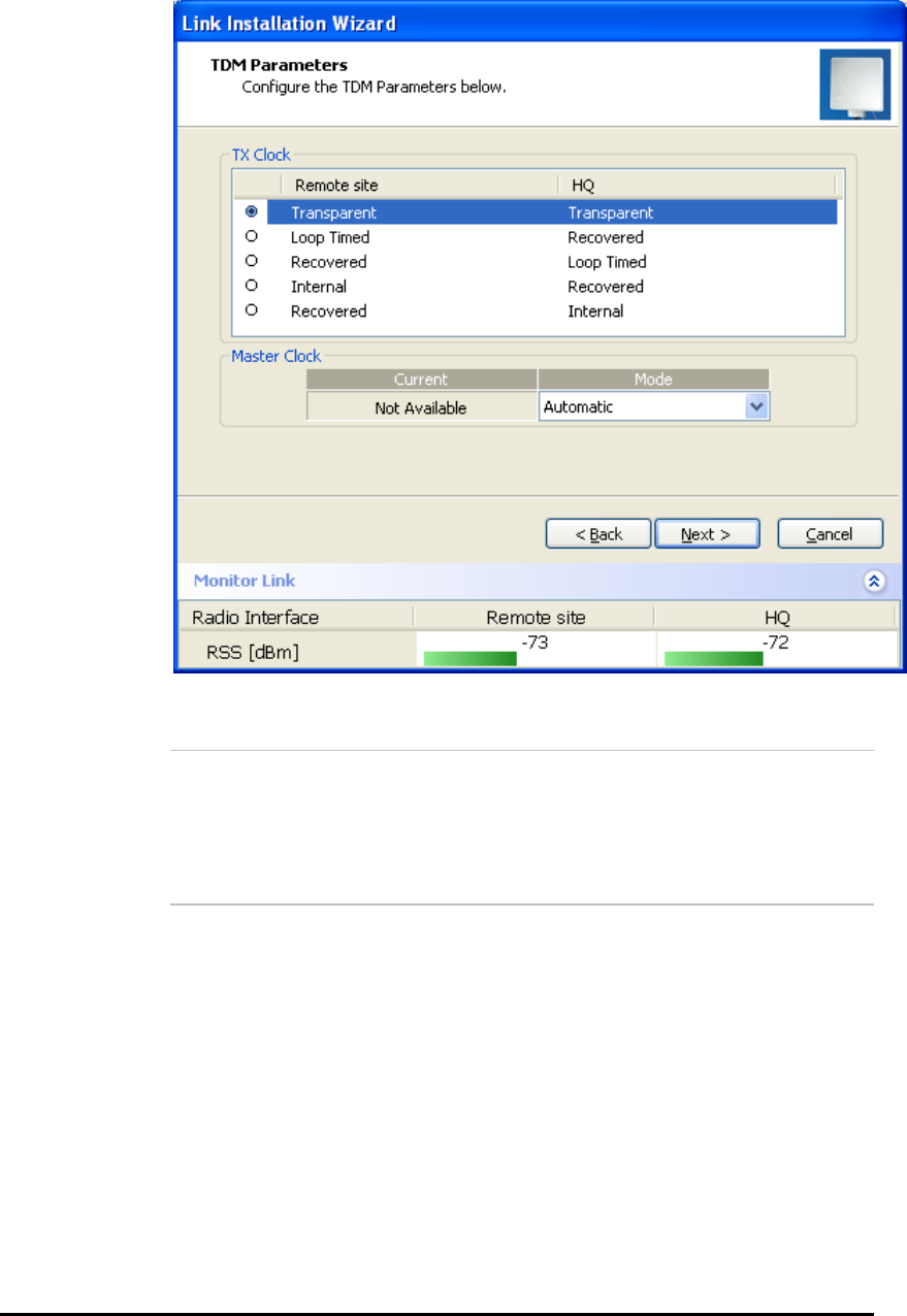
WinLink User and Installation Guide Version 1.795 3-43
Figure 3-16: TDM Parameters dialog box
9.
Note:
This dialog box is available with IDU-E and IDU-C units; it is activated
after TDM service is chosen in the previous Service dialog box. In
Ethernet only services, the TDM dialog box does not appear.
Setting the T1 Line Code
The T1 line code can be set as B8Zs or AMI in the TDM Parameters
dialog box.
The default is B8ZS.
Æ To change the line code
• In the TDM Parameters dialog box, set the line code to B8ZS or
AMI.

WinLink User and Installation Guide Version 1.795 3-44
Setting the TDM Backup (for IDU-R only)
IDU-R units have two E1 trunk lines, one for WinLink air interface via
the ODU, and the second external equipment such as a PBX. The TDM
backup screen is displayed in IDU-R systems only.
The external equipment status is displayed on the Main screen of the
Manager in IDU-R systems.
Figure 3-17: External Equipment Status
To use the Backup Mode
1. Click Enabled Backup Mode.
2. Set which link is backup link; either WinLink or the external
equipment.
The second link becomes the main link.
To disable the Backup mode
1. Click Disable Backup Link
2. Set which link is the Main Link; either WinLink or the external
equipment.
Figure
3-18
shows the TDM Backup Service screen.
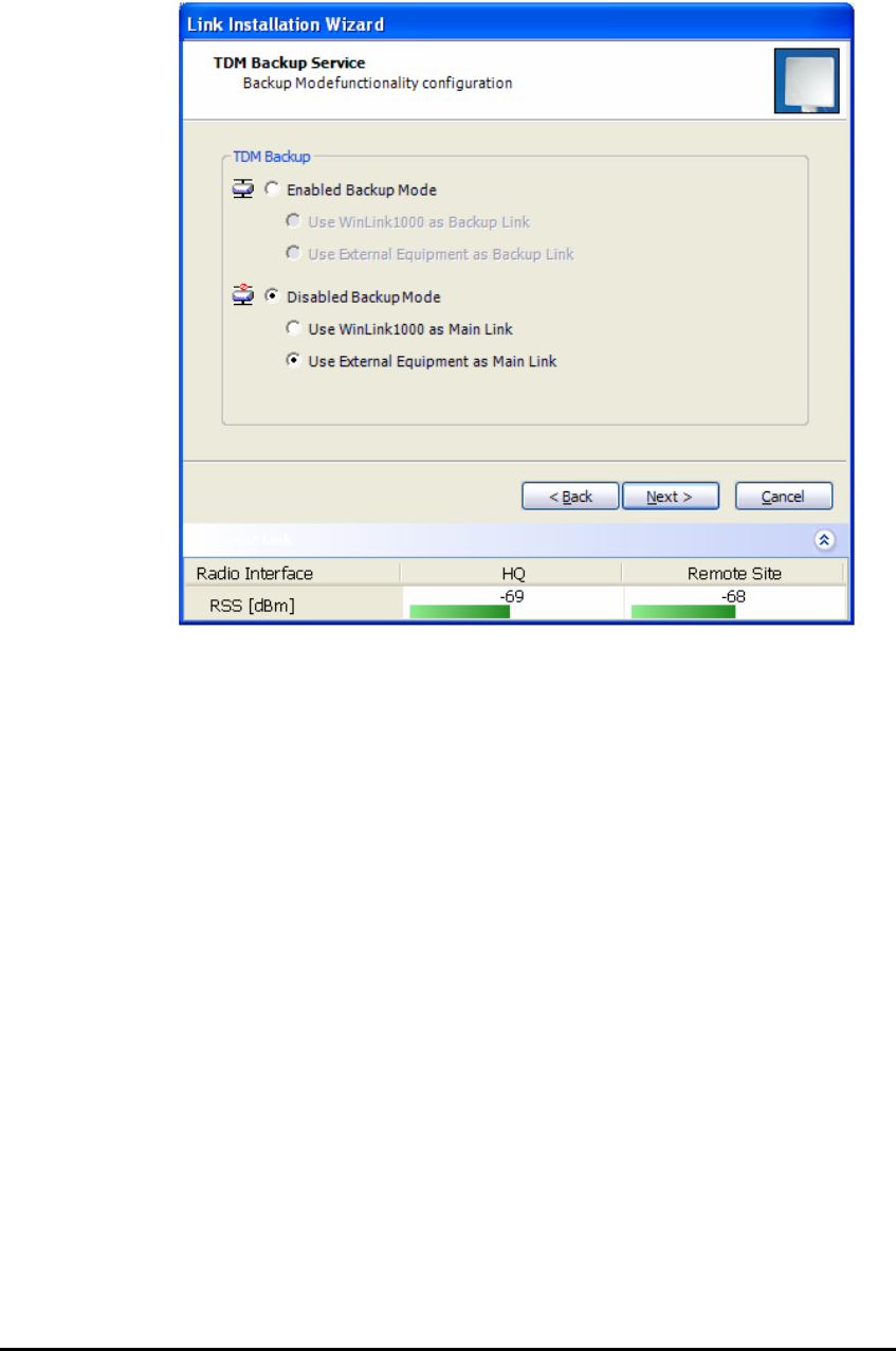
WinLink User and Installation Guide Version 1.795 3-45
Figure 3-18: TDM Backup Service, IDU-R units only
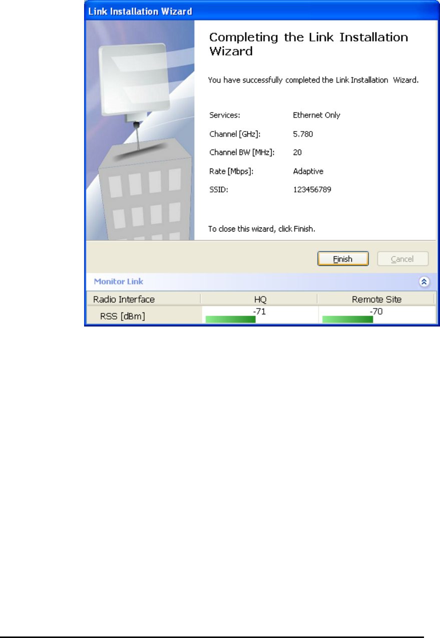
WinLink User and Installation Guide Version 1.795 3-46
Figure 3-19: Installation Wizard, Finish Screen
3. Click Finish to complete the installation wizard.
Verify that the Radio Signal Strength (RSS) is according to expected
results as determined by the Link Budget Calculator.
Verify that the Radio Signal Strength (RSS) numerical value is
relative to the expected results that were determined by the Link
Budget Calculator.

Chapter 4
Getting Started
This section provides the following information for WinLink:
• Turning the system on and off
• Starting the WinLink™ Manager software
• Controls and indicators
• Normal Indications
• Default settings
• Technical Specifications
Turning On WinLink
Æ To turn on WinLink:
• Connect the AC/DC converter to the IDU power connector and
to the mains. See Connecting Power to an IDU for full
instructions on connecting the power.
The PWR indicator lights up (IDU-E only) and remains lit as
long as the IDU is receiving power.
Controls and Indicators
WinLink requires no operator attention once installed, with the
exception of occasional monitoring of front panel indicators and
statistics data. Intervention is only required when WinLink must be
configured to its operational requirements, or diagnostic tests are
performed.
IDU Front Panel Indicators
The front panel of the IDU-C and IDU-E includes a series of LED
indicators that show the operating status of the unit.
The following figure shows the IDU-E front panel:

WinLink User and Installation Guide Version 1.795 4-48
Figure 4-1: IDU-E Front Panel
The following table describes the indicators:
Table
4-1: Front Panel LEDs
Name Color Function
PWR Green ON –Power supply is ON (IDU-E only)
IDU
With Ethernet only
With TDM
Green
Green
Orange
Red
ON – IDU operational
ON – During power-up only
ON - During power-up only
ON – Failure
ODU Green
Red
ON – ODU-to-IDU communication link is operating
ON – ODU-to-IDU communication link is disrupted
LINK Green
Orange
Red
ON – Wireless link is synchronized
ON – During installation mode only
ON – Wireless link lost synchronization
SERVICE Green
Orange
Red
ON – E1 or T1 line is synchronized
ON – Alarm detected at the remote interface
ON – Local or Remote loopback
ON – Alarm detected at the local interface
ODU/LAN Indicators
The ODU/LAN and TDM connectors (IDU-E rear panel, IDU-C front
panel) have LED indicators that show the operating status. The
following tables describe the indicators.
Table
4-2: ODU/LAN LEDs
Name Color Function Location
LINK Green On – Good Ethernet link integrity ODU/LAN
connectors
ACT Orange Blinks according to the Ethernet
traffic
ODU/LAN
connectors

WinLink User and Installation Guide Version 1.795 4-49
IDU Back Panel Indicators
Table
4-3: TDM Traffic Indicators
Function Green LED Red LED
OK On Off
AIS Off On
LOS On On
Loopback On Blinking
Upon turning on WinLink, the PWR LED in the IDU-E front panel lights
to indicate that WinLink is on.
Table
4-4
shows the correct status of
the indicators at power-up.
Table
4-4: WinLink Indicators at Startup
Indicator Color Status
PWR Green ON (IDU-E only)
IDU
With Ethernet only
With TDM only
Green
Orange
Green
ON for short duration during startup
ON for short duration during startup
For normal operation after successfully connecting
the ODU to the IDU.
ODU Green ON shows normal operation
LINK Orange
Green
ON for short duration during startup
ON shows normal operation
SERVICE Green ON shows normal operation
OFF when Service is configured for Ethernet only
If the above LED indications do not appear following initial power turn-
on, refer to
Chapter 5
for the diagnostic test instructions.
ODU Indicators
Color Function Location
Green Blinking – Good Ethernet link
integrity
IDU/LAN
connectors
Orange On - during power on self test IDU/LAN
connectors
Default Settings
Table
4-5
lists the default settings of the WinLink configuration
parameters
.

WinLink User and Installation Guide Version 1.795 4-50
Table
4-5: Default Settings
Parameter Default Value
ODU IP Address 10.0.0.120
Subnet Mask 255.0.0.0
Manager Login password Admin
SSID –
Link Password Wireless-bridge
Rate Adaptive
Services Ethernet
Ethernet Configuration Auto Detect
Radio Link Failure Actions No action
Bridge Non PoE systems: Hub Mode, Aging time = 300 sec
PoE systems: Bridge Mode
Community values Read-write – netman
Read-only – public
Starting the WinLink Manager Software
Æ To start the WinLink™ 1000 Manager:
1. Connect the management station to the LAN.
2. Double-click the WinLink™ 1000 Manager icon on the desktop, or
click Start > Programs > WinLink™ 1000 Manager.
The Login dialog box appears.

WinLink User and Installation Guide Version 1.795 4-51
Figure 4-2: Login Screen
3. For IP Address do one of the following:
• Type an IP address for the ODU (for Network mode), OR
• Click Local Connection (if you are connected directly to the IDU
LAN port).
The default IP address for the ODU is 10.0.0.120. The Subnet mask
is 255.0.0.0. For Versions 1.700 and greater, any valid subnet mask
may be used.
4. Enter the password
1.
Note:
The actual IP address is defined during link configuration (see Defining
the Management Addresses
)
.
Default password –
admin
(see the section on Changing the
Management Password)
5. If you are a user with Read-Write permission, click Options to enter
the community options.
WinLink™ 1000 is protected with Community passwords. A user
may be defined with read-only permission or with read-write
permission. See the section Changing Community Values for more
detail.
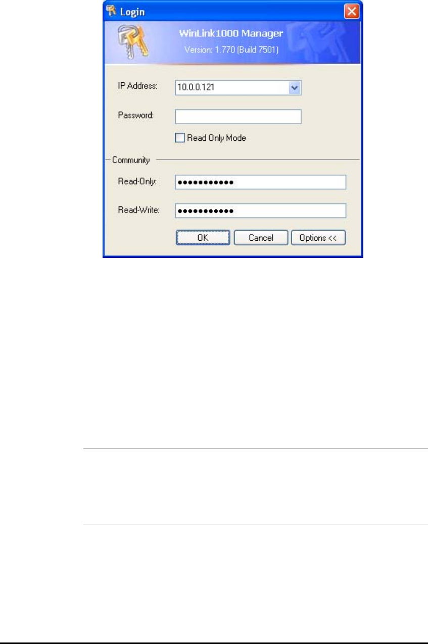
WinLink User and Installation Guide Version 1.795 4-52
Figure 4-3: Login Screen with Community Options Visible
• If using the system for the first time, leave the default
community passwords, netman for read-write, and public for
read-only.
• If community values were previously defined, enter them
under Community in the Read-Only or Read-Write boxes.
• If you are a user with read-only permission, click the Read
Only Mode check box.
The WinLink™ 1000 Manager main screen is displayed (see
Figure
4-4).
Note:
With BRS systems the link must be activated at both sites when
installing for the first time. A red Inactive Link box appears in the
center of the Manager screen. Activation is performed later.
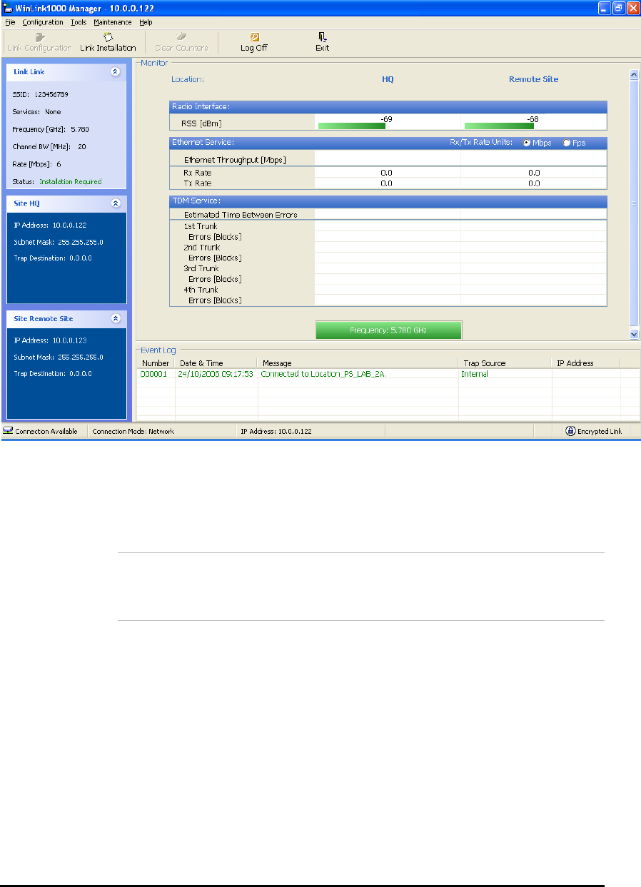
WinLink User and Installation Guide Version 1.795 4-53
Figure 4-4: WinLink™ 1000 Manager Main Screen
Over the Air Connection indication
During the login the Manager reports on over the air connection.
Note:
Over the Air connection to remote unit is not recommended
• Select the relevant option for your login requirements.
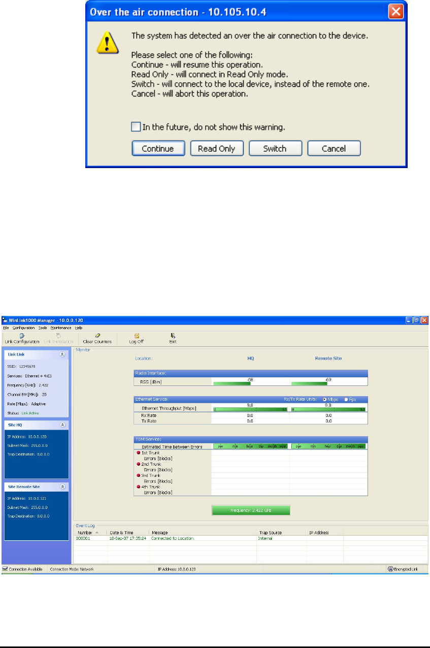
WinLink User and Installation Guide Version 1.795 4-54
Figure 4-5: Over the Air Connection
Managing WinLink
Before starting a management session, make sure that a
communication link between local and remote units exists. The Link
Status indication bar in the middle of the Main menu must be green
and the
Radio Link - Sync
message must appear in the event log (see
Figure
4-6
).
Figure 4-6: Main Screen, Wireless Link is Active
The WinLink™ 1000 Manager Main screen consists of the following
elements:

WinLink User and Installation Guide Version 1.795 4-55
Toolbar buttons
Link Configuration Changes configuration parameters of operating
wireless link; assigns text files for storing alarms,
statistics and configuration data
Link Installation Performs preliminary configuration of the system
This button is disabled once a link is defined.
Clear Counters Clears error counters (available with TDM only)
Log off Logs off WinLink™ 1000 Manager
Exit Exits WinLink™ 1000 Manager
Menu bar
File Log off, and exit
Configuration Use for link configuration, individual site configuration or
link installation
Tools Acesses Performance Monitoring Report, Active Alarms,
Change password, Event log handling, Set Preferences
Maintenance Provides the following functions: Clear counters,
Loopbacks, System Reset.
Help Provides WinLink™ Manager Help, Link Budget Calculator,
Get Link Information About WinLink
Link details pane
• Summarizes information on the radio frequency, IP address,
type of TDM service, number of assigned E1 or T1 timeslots,
and IP details of the local and remote WinLink units.
Monitor pane
• Displays the link quality between local and remote devices and
the following statistics:
• Radio signal strength (RSS) in dBm
• Current Ethernet bandwidth in Mbps. This is not the actual
traffic rate, but the maximum capacity (Net symmetrical
Throughput “Full-Duplex”) that can be supported currently,
(see
Figure
4-7
).
The scale on the bar varies depending on the link distance and
air interface quality.
• Local/remote receive and transmit traffic rate, in Mbps or Fps
(frames per second).
• TDM status
The Estimated Time Between Errors bar gives an indication of
the TDM quality. The ETBE constantly calculates the expected
TDM ratio according to the current air interface conditions.
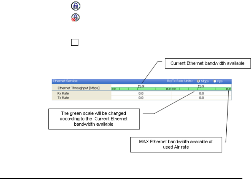
WinLink User and Installation Guide Version 1.795 4-56
• Link Status: Shows the channel frequency. The color of the
box indicates the status.
Green is an active link
Red is an inactive link
Magenta shows an authentication or compatibility problem
Brown shows severe compatibility problem.
• Event log – stores alarms generated by local and remote units.
Status Bar
Displays the following icons:
• Connectivity icon showing how the device is connected to the
Ethernet.
• Network connection to the local unit – using IP of the local
unit
Over the Air connection - using IP address of the remote for
over the air connection
Local mode using broadcast - direct connection to IDU LAN
port without IP address. This mode is only recommended
when the managed PC is connected directly to the IDU (no
network involved) the managed PC must have a static IP
configured. (No DHCP)
• Encryption icon showing if the link is encrypted
encrypted link
Link Password Validation failed. The link is encrypted with
default keys. Service and configuration is unavailable. Need to
change the link password in either site
No Encryption – an older release is used. No encryption is
available
Figure 4-7: Ethernet Bandwidth Indication

WinLink User and Installation Guide Version 1.795 4-57
Æ To change link configuration parameters:
1. In the Main menu, click Configure Link.
The Configure Link wizard appears. See Link Configuration Wizard
for configuration details.
2. Click Next.
3. Continue through the configuration wizard and define the Link
name and ID, Channel, Rate and Services.
4. Once you finish changing configuration parameters, click Finish.
The system takes a few seconds to activate the link with the new
configuration.
Turning Off WinLink
Æ To turn off WinLink:
1. Exit the management application.
2. Remove the AC/DC converter power cord from the mains.

Chapter 5
Configuring the Link
This chapter describes configuration procedures, which are performed
after the physical installation of the local and remote WinLink units and
after the Installation Link wizard has been run. A Link Configuration
wizard is used to redefine the configuration parameters if necessary.
Both the HQ and sites in the link are defined simultaneously (both
sides of the link are defined simultaneously).
The following parameters are configured via the Site Configuration
Wizard:
• System parameters
• Frequency channel
• Air interface rate
• Service parameters
• TDM
• Hub Site Synchronization Settings.
The following parameters are configured via the Configuration dialog box.
• Transmit power
• Management and trap addresses
• Bridge mode
• Ethernet mode
• Community values.
For HSS screens see
Hub Site Synchronization.
After installing the link, the system configuration can be modified.
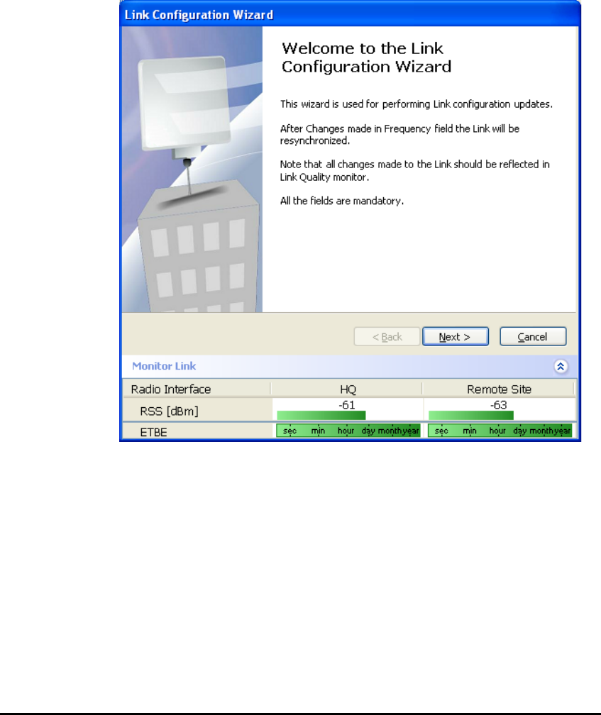
WinLink User and Installation Guide Version 1.795 5-59
Link Configuration Wizard
Configuring System Parameters
Æ To change general parameters:
1. In the Main menu, click the Link Configuration button.
The Configuration wizard opens:
Figure 5-1: Configuration Link Wizard
2. Click Next.
The Link Configuration dialog box appears:
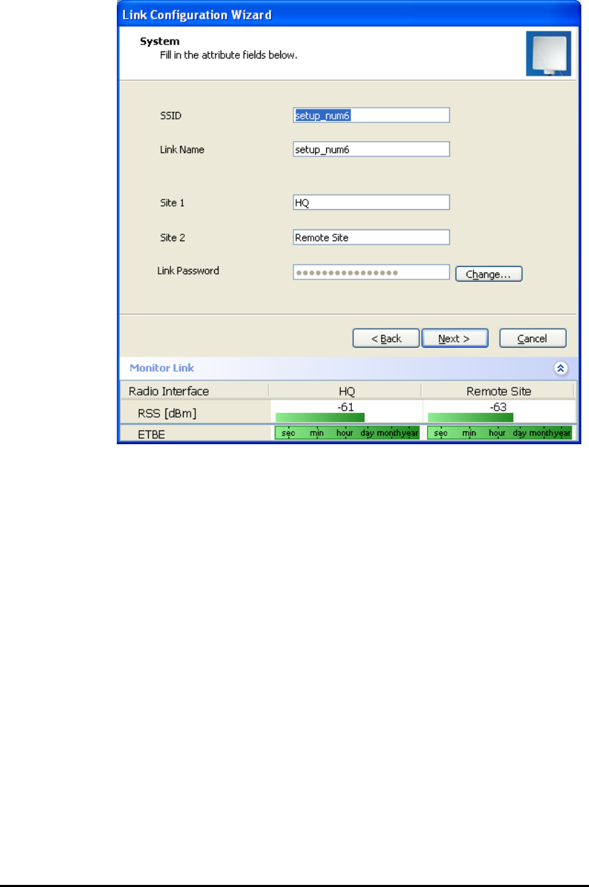
WinLink User and Installation Guide Version 1.795 5-60
Figure 5-2: Link Configuration, System dialog box
3. In the System dialog box, enter the new data for the link. All fields
with a white background can be edited.
4. Click Next.
The Channel Settings dialog box appears.
Selecting Channels: Automatic Channel Select
You are required to define the operating frequency channel. Newer
versions have a feature called Automatic Channel Select (ACS). This
allows you to define several allowable frequency channels to which you
can change if interference is detected on the channel in use. ACS
performs channel monitoring and selects the channel with the lowest
interference for the transmission.
Automatic Channel Select enables coexistence with any radar system
that may be active in the area.
Note: For the ETSI version, skip to page 5-62; for the BRS version,
skip to page 5-64.
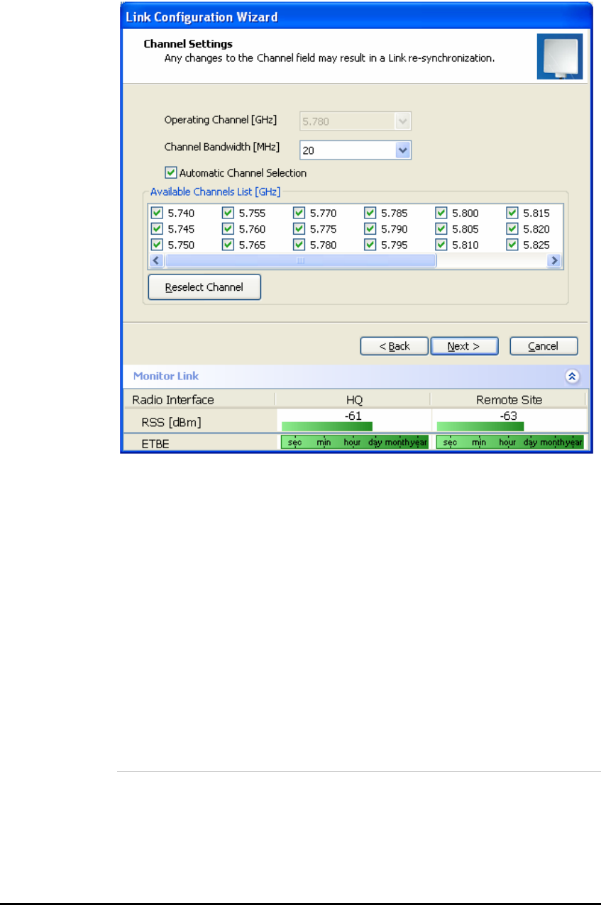
WinLink User and Installation Guide Version 1.795 5-61
Figure 5-3: Channel Select dialog box - Automatic Channel Select
Æ To define automatic channel selection:
1. Select the main frequency from the Operating Channel menu.
2. Select the required Bandwidth 5, 10, or 20 MHz.
3. Click the check box if Automatic Channel Selection is required.
4. Click the check boxes in the Available Channels List of all the
allowable channels that can be automatically selected.
5. If you are not satisfied with the channel that is selected
automatically, click Reselect Channel.
A new channel will be selected from one of the Available Channels
that have been defined.
Note:
By clicking Reselect Channel, the ODU scans the selected channels
looking for radio frequency activity. Once it determines which of the
channels is free of RF signal activity, it locks onto it. If you require a
different channel than the one selected, you must first remove the
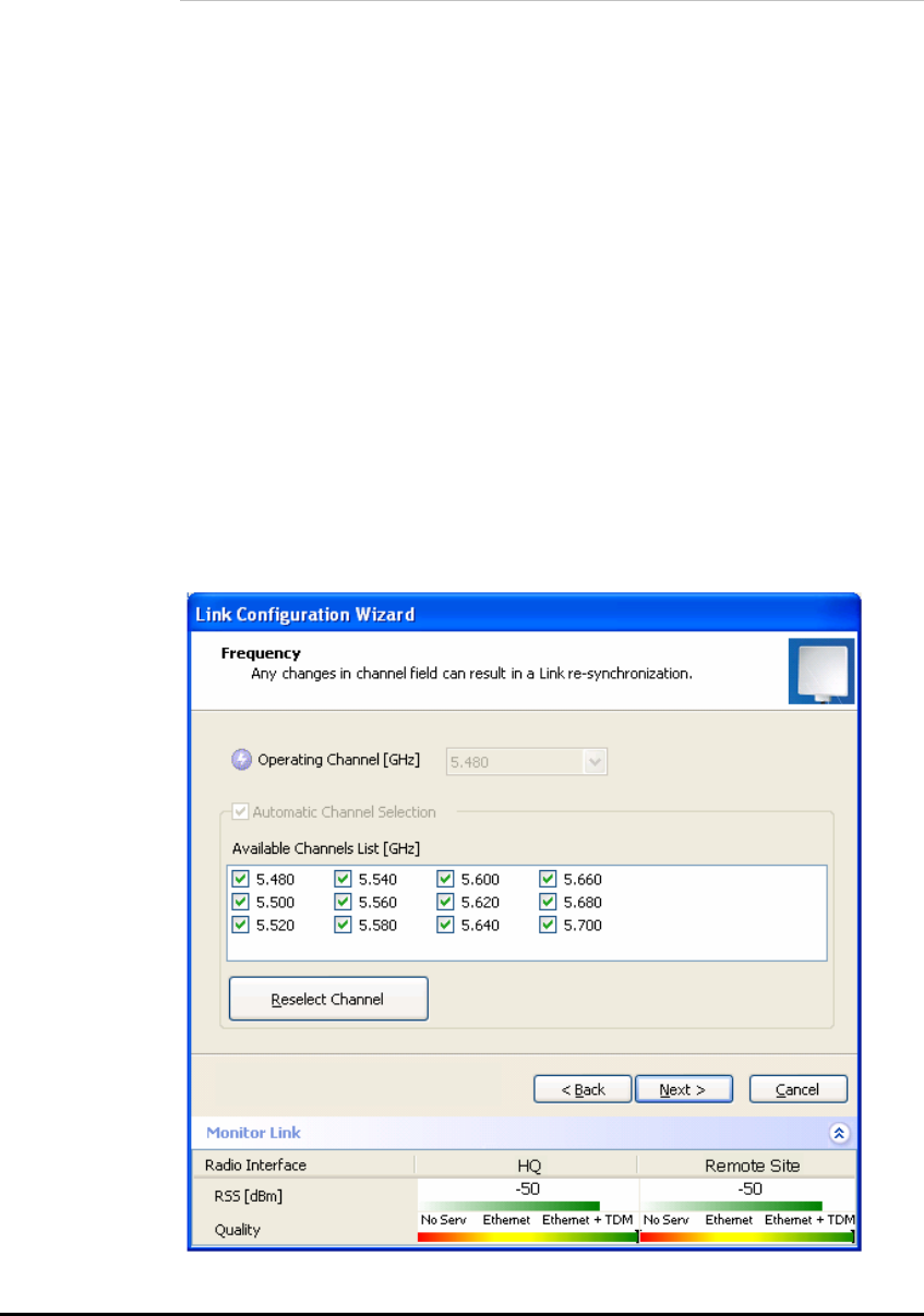
WinLink User and Installation Guide Version 1.795 5-62
operating channel that the ODU finds most free of RF signal activity
from the available channel list.
6. Click Next.
The Rate Select box appears.
Note: If you have the standard version, proceed to Configuring
Service Parameters, page 5-65. For the ETSI version, proceed to the
next section; for the BRS version, skip to page 5-64.
The 5.4 GHz ETSI Version
In accordance with ETSI, unlicensed wireless data equipment is not
allowed to interrupt radar services. Therefore, if the ETSI Version
detects Radar activity, it automatically changes the frequency channel.
This feature is termed Dynamic Frequency Selection (DFS). According
to the standard, a channel with active Radar is prohibited from use for
30 minutes. Before any transmission, WinLink™ probes a channel for
Radar signals for a period of 60 seconds.
In the 5.4 GHz ETSI version, the Automatic Channel Selection is
selected by default and a minimum of two channels must be defined as
available.
Figure 5-4: Channel Select dialog box (DFS, ETSI requirement)

WinLink User and Installation Guide Version 1.795 5-63
The sign on the configuration Wizard and Status bar indicates that
the radar detection is on.
Æ To define automatic channel selection in the 5.4 ETSI version
1. Select the main frequency from the Operating Channel menu.
Note:
Automatic Channel Selection is selected by default.
2. Click at least two check boxes in the Available Channels List of all
the allowable channels that can be automatically selected.
Note:
Installation will not continue until at least two channels are defined.
Selecting a new channel causes the system quality to change. The
quality bar shows the adjustment until the system finds the best
quality link.
Any channel selected is evaluated for 60 seconds; therefore this
selection process may take a few minutes.
3. If you are not satisfied with the channel that is selected
automatically, click Reselect Channel.
A new channel will be selected from one of the Available Channels
that have been defined.
Note:
The reselection process may take a few minutes.
4. Click Next.
The maximum rate is selected according to the link conditions
The quality bar may fluctuate until the system finds the best quality
link.
5. Click Next.
The Service Parameters dialog box appears. Proceed to page 5-65.
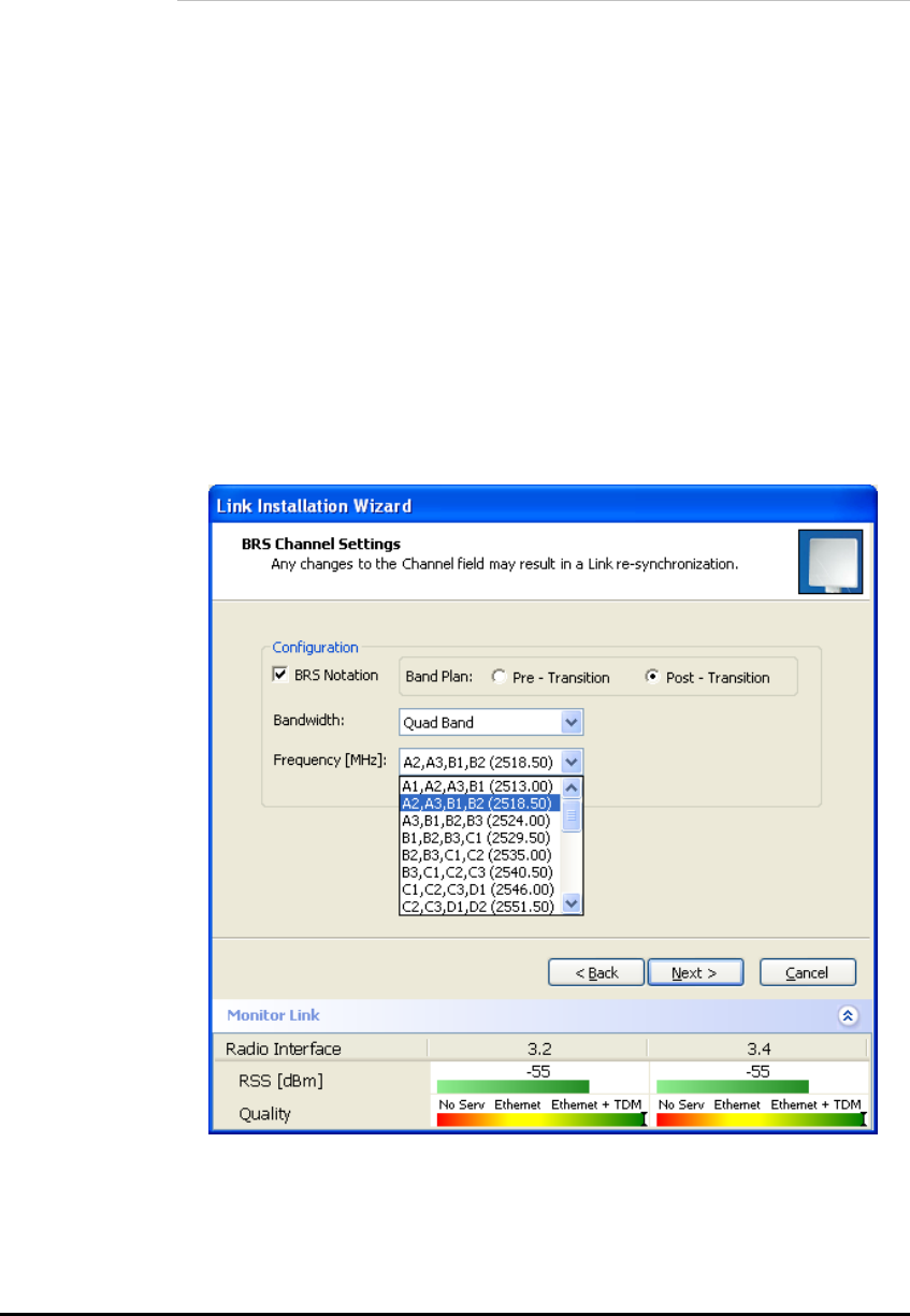
WinLink User and Installation Guide Version 1.795 5-64
BRS Version: Configuring BRS Channel Settings
Note:
Both sites in a BRS Link must be configured identically.
Æ To Configure BRS Channel Settings
1. Select the Band Plan: Pre-Transition or Post-Transition.
2. Select the Bandwidth required.
• Single Band (5MHz)
• Double Band (10MHz)
• Quad Band (20MHz)
3. Select the Frequency.
4. Click Next. The system is re-synchronized to the changes.
Figure 5-5: BRS Channel Settings Post-Transition

WinLink User and Installation Guide Version 1.795 5-65
Configuring Service Parameters
You define the type of service required, Ethernet Only or Ethernet with
TDM. The bandwidth remaining available for Ethernet if TDM services
are required is shown in the dialog box.
Note:
ACCESS versions are Ethernet Only.
In the Service Parameters dialog box select the number of E1
connections (x1 or x2 for IDU-E, or x4 for IDU-C). Define the required
transmission rate, and the distance between the sites.
Æ To configure E1/T1 and Ethernet services:
1. In the Service dialog box, select one of the following:
• Ethernet plus a number of E1/T1 channels (see
Figure
5-6
).
• Ethernet data only.
2. Select the transmission rate required.
• Adaptive
• 9 Mbps
• 12 Mbps
• 18 Mps
• 24 Mbps
• 36 Mbps
• 48 Mbps
The default rate is Adaptive. ACCESS versions only operate in
Adaptive mode.
Adaptive Modulation - The system changes modulation
automatically depending on channel characteristics in order to
guarantee continuation of service. The adaptive modulation
enables the user to maximize Ethernet throughput without
degradation of the TDM service quality. When Ethernet only service
is used, the adaptive modulation enables improving the Ethernet
performance in case of air performance degradation (periodical
interference or RSS changes).
In event of interference at one site, there is no need to use a lower
modulation at the other site (as in previous versions). In such a
case the actual rate changes automatically only at the problematic
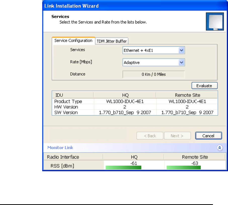
WinLink User and Installation Guide Version 1.795 5-66
site, while the second side of the link maintains the highest rate
possible (Asymmetric).
Adaptive modulation can be changed in both Installation and
Configuration wizards.
For versions 1.6 and greater, distance between the sites is
automatically measured.
If TDM services are selected, then the Evaluate icon shows on the
screen while the maximum rate is evaluated.
When evaluation is complete the icon changes and the following
message is shown:
Service has been evaluated, click Next to continue.
3. Click Next.
The TDM Parameters dialog box or the Finish screen appears
depending on which services were selected.
Figure 5-6: Services Dialog Box, E1/T1 Interface
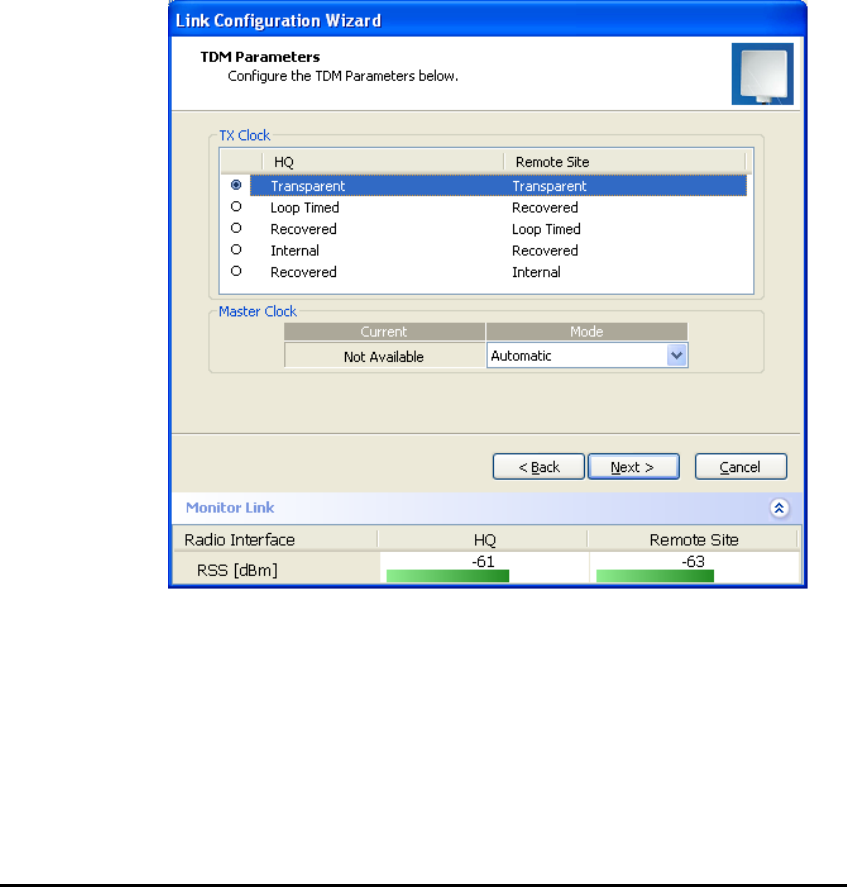
WinLink User and Installation Guide Version 1.795 5-67
Configuring TDM Operation
Setting the Clock Configuration
The TDM clock feature is enabled for carrier class IDU-C in addition to
the hardware version 2 and greater IDU-E with TDM. A TDM dialog box
will appear where IDU supports the clocking configuration feature (see
Figure
5-7
and
Figure
5-8
).
A new master clock configuration option is available in the Link
Configuration Wizard. The automatic mode selects the clock from the
first trunk that is working in normal mode (or is configured to loop-
back maintenance). If a specific trunk is selected, this trunk shall be
used as the system master regardless of the trunks state. The current
master clock trunk is also displayed.
Figure 5-7: TDM clock dialog box for T1 IDU
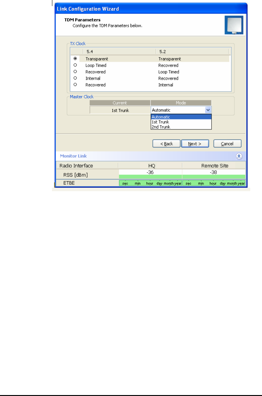
WinLink User and Installation Guide Version 1.795 5-68
Figure 5-8: TDM clock dialog box for E1 IDU
If TDM services are selected then the TDM parameters dialog box
appears.
The TDM Parameters dialog box contains five working modes; select the
appropriate clock mode according to your application. Choosing one of
these modes sets the TDM clock behavior on both sides of the link. The
user equipment must be configured as described in
Chapter 3
.

WinLink User and Installation Guide Version 1.795 5-69
Transparent/Transparent
WinLink™ regenerates the clock from line clock side to Tx
clock on the opposite side of the link.
Loop time/Recover
The local unit receive clock is the transmit clock on both sides
of the link.
Recover/Loop time
The remote unit receive clock is the transmit clock on both
sides.
Internal/Recover
The local unit internal oscillator generates the clock while the
remote unit recovers this clock.
Recover/Internal
The remote unit internal oscillator generates the clock while
the local unit recovers this clock.
Note:
The Line code option is used with T1 Systems.
Table
5-1: TDM Clock Modes
Unit Clock Mode User Equipment Side
Local Unit Remote Unit HQ side Branch side
1 Transparent Transparent Internal/Recover Internal/Recover
2 Loop Time Recover Internal Recover
3 Recover Loop Time Recover Internal
4 Internal Recover Recover Recover
5 Recover Internal Recover Recover
Setting the T1 Line Code
The T1 line code can be set as B8Zs or AMI in the TDM Parameters
dialog box.
The default is B8ZS.
Note:
This dialog box is available only when TDM service was selected in the
previous Services dialog box.

WinLink User and Installation Guide Version 1.795 5-70
Æ To change the line code
1. Run the Configuration wizard until you reach the Services dialog
box.
2. Verify that T1 services have been selected.
3. Click Next to open the TDM Parameters dialog box.
4. Set the line code to B8ZS or AMI as required.
5. Click Next.
Setting the TDM Backup (IDU-R only)
The IDU-R units have two E1/T1 trunk lines, one for WinLink™ air
interface via the ODU, and the second external is for peripheral
equipment- I.E. PBX. The external equipment status is displayed on the
Main screen of the Manager in IDU-R systems.
Figure 5-9: IDU-R - External Equipment Status
Æ To use the Backup Mode
1. Click Enabled Backup Mode.
2. Set which link is backup link; either the link or the external
equipment.
The second link becomes the main link.
3. Click Next to continue.
Æ To disable the Backup mode
1. Click Disable Backup Link
2. Set which link is the Main Link; either the link or the external
equipment.
3. Click Next to continue.
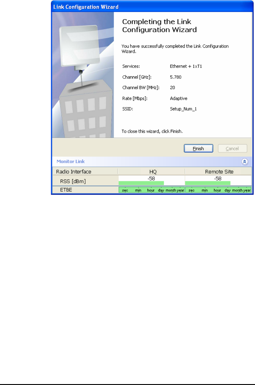
WinLink User and Installation Guide Version 1.795 5-71
Figure 5-10: Configuration Link, Finish screen
The Finish screen appears, showing a summary of the link
configuration (see
Figure
5-10
) above.
4. Click Finish to complete the configuration wizard.
The Main screen is displayed.
Configuring the Site
Editing the Configuration Parameters by Site
You can edit the configuration parameters for each site individually.
The following functions are available from either the left side of the
dialog box, or the buttons on the top of the dialog box (see
Figure
5-11
).
Functions on the left of the dialog box:
System Edit the contact person and location details.
View the system details
Air Interface Change the transmit power

WinLink User and Installation Guide Version 1.795 5-72
Inventory View the hardware and software inventory.
Management Configure the IP address, Subnet Mask,
Default Gateway, and the Trap Destination.
Security Change the Community Values and the Link
Password
Date and Time Set the date and time of the server and of
the System.
Advanced Configure the Bridge, define the LAN
connection and set the external alarm
inputs.
Functions at the top of the dialog box:
Backup Save a backup.ini file with the current
configuration.
Restore Load the backup.ini file created by the
backup.
Installation Mode Return to Installation Mode for the entire
link.
Selecting the Mute check box before clicking
the Install Mode button mutes the Beeper.
Mute Mutes the alignment tone at startup.
Reactivate the beeper during alignment.
Æ To edit the Configuration Parameters:
1. Click Configuration from the main menu.
2. Select which site to configure.
The Configuration dialog box opens. (See
Figure
5-11
)
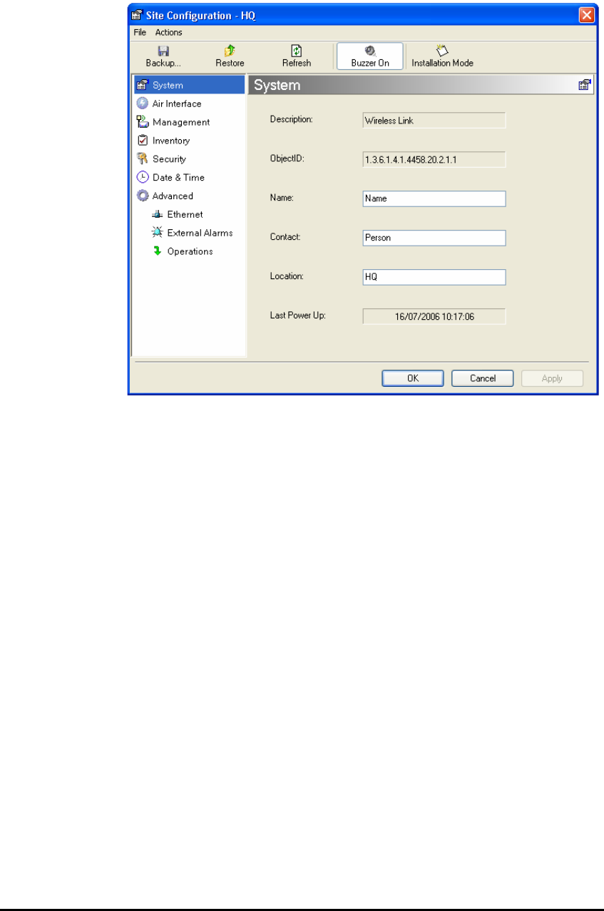
WinLink User and Installation Guide Version 1.795 5-73
Figure 5-11: Configuration Dialog Box
3. Select the appropriate item in the left hand list to open a dialog
box.
4. Click Apply to save changes.
Changing the Transmit Power
Each site can have a different transmit power level.
Æ To change the Transmit Power:
1. Click Configuration from the main menu.
2. Select which site to configure.
The Configuration dialog box opens.
3. Select Air Interface. (See
Figure
5-12
)
4. Select the required Transmit Power Level. For available power
limits for each system, see
Product Specification Table, page I-160.
5. Click Apply to save the changes.
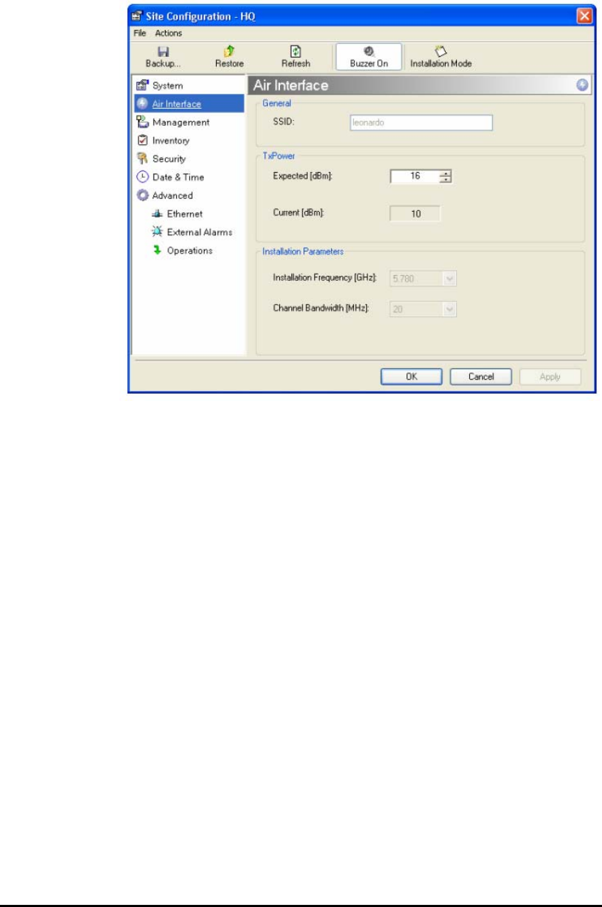
WinLink User and Installation Guide Version 1.795 5-74
Figure 5-12: Changing the Transmit Power
Defining the Management Addresses
Each site must be configured separately, first site A then site B.
Æ To define the Management Addresses:
1. Click Configuration from the main menu.
2. Select which site to configure.
The Configuration dialog box opens:
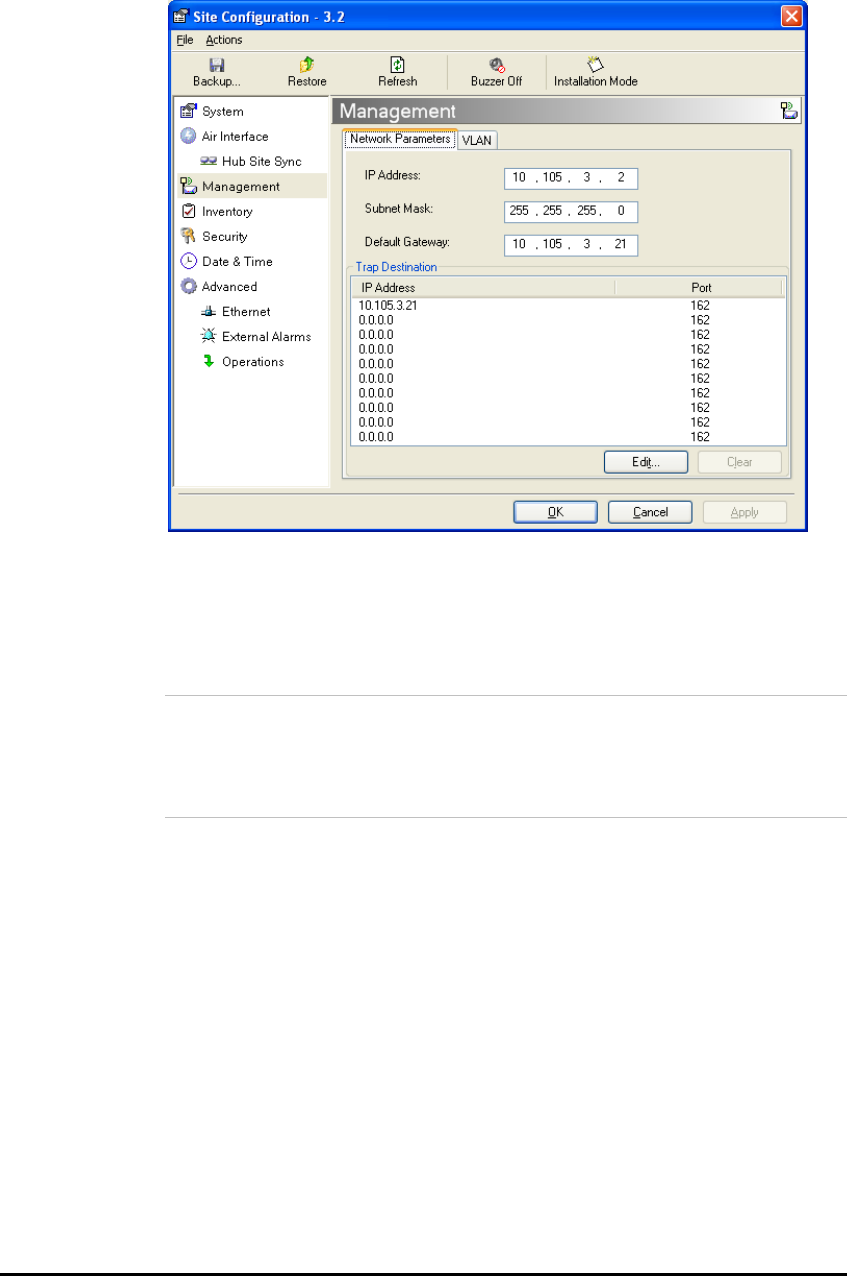
WinLink User and Installation Guide Version 1.795 5-75
Figure 5-13: Management Addresses - Site Configuration dialog box
3. Select Management.
4. Enter the IP address of the ODU in the IP address field.
Note:
If performing configuration from the WinLink™ 1000 Manager, the IP
address is entered in the login screen.
5. Enter the Subnet Mask.
6. Enter the Default Gateway.
7. Enter the Trap Destination. This is the IP address of the PC running
the management application. The event log will be stored at this
address.
8. Click Apply to save the changes.
Configuring VLAN Settings
VLAN Management enables separation of user traffic from NMS Traffic.
The user decides if such a separation is required. Both the HQ and
Remote site are configured with VLAN Management.
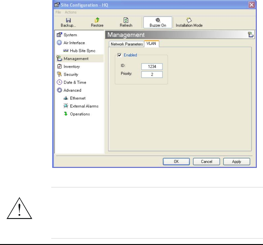
WinLink User and Installation Guide Version 1.795 5-76
Æ To enable VLAN management:
1. Click Configuration from the main menu.
2. Select which site to configure (HQ or Remote site).
3. Select Management.
4. Open the VLAN tab.
5. Check The Enabled box.
6. Enter a VLAN ID.
After entering the VLAN ID, only packets with the specified VLAN ID
are processed by the ODU. This includes all the protocols supported
by the ODU (ICMP, SNMP, TELNET and NTP). The VLAN priority is
used for the traffic sent from the ODU to the management
workstation. VLAN management affects all types of management
connections (local, network and over the air).
7. Enter a Priority number.
Figure 5-14: Configuring VLAN Settings
Changing this parameter causes the management application to
immediately disconnect. In order to avoid problems, it is recommended
to verify the change by setting the VLAN only to one ODU, and only
after verifying the VLAN network operation, change the other VLAN
setting can be changed.
Warning

WinLink User and Installation Guide Version 1.795 5-77
Troubleshooting:
If the VLAN ID is forgotten or there is no VLAN network connected to
the ODU:
• Reset the device.
In the first two minutes both VLAN and no VLAN connections
are available.
Setting the Date and Time
The ODU maintains a date and time value. The date and time value
should be synchronized with any Network Time Protocol (NTP) version
3 compatible server1. On power-up the ODU configures the initial date
and time using an NTP server. If the server IP is not configured or is
not reachable, a default time is set. When configuring the NTP server
IP, you should also configure the offset from the Universal Coordinated
Time (UTC). If there is no server available, you can either set the date
and time, or you can set the manager workstation time. Note that
manual setting is not recommended since reset, power up, or
synchronization with an NTP server will override the setting.
Note:
The NTP uses UDP port 123. If a firewall is configured between the
ODU and the NTP server this port must be opened
2
.
It can take up to 8 minutes for the NTP to synchronize the ODU date
and time.
Æ To set Date and time
1. Click Configuration from the main menu.
2. Select which site to configure.
The Configuration dialog box opens.
3. Select Date & Time:
1Windows XP is configured by default as a server.
2 Windows XP command w32tm /stripchart /computer:<server IP> can
be use to check the NTP server connectivity
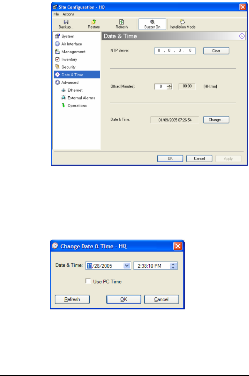
WinLink User and Installation Guide Version 1.795 5-78
Figure 5-15: NTP Server Address - Site Configuration dialog box
4. If entering an address for the NTP Server, click Clear, and then
enter the new address.
5. Set the Offset value.
6. To manually set the date and time, click Change and edit the new
values.
Figure 5-16: Change Date and Time - HQ dialog box
Configuring the Bridge
Bridge configuration is required in various network topologies, such as
protection (1+1) and ring application. The bridge configuration
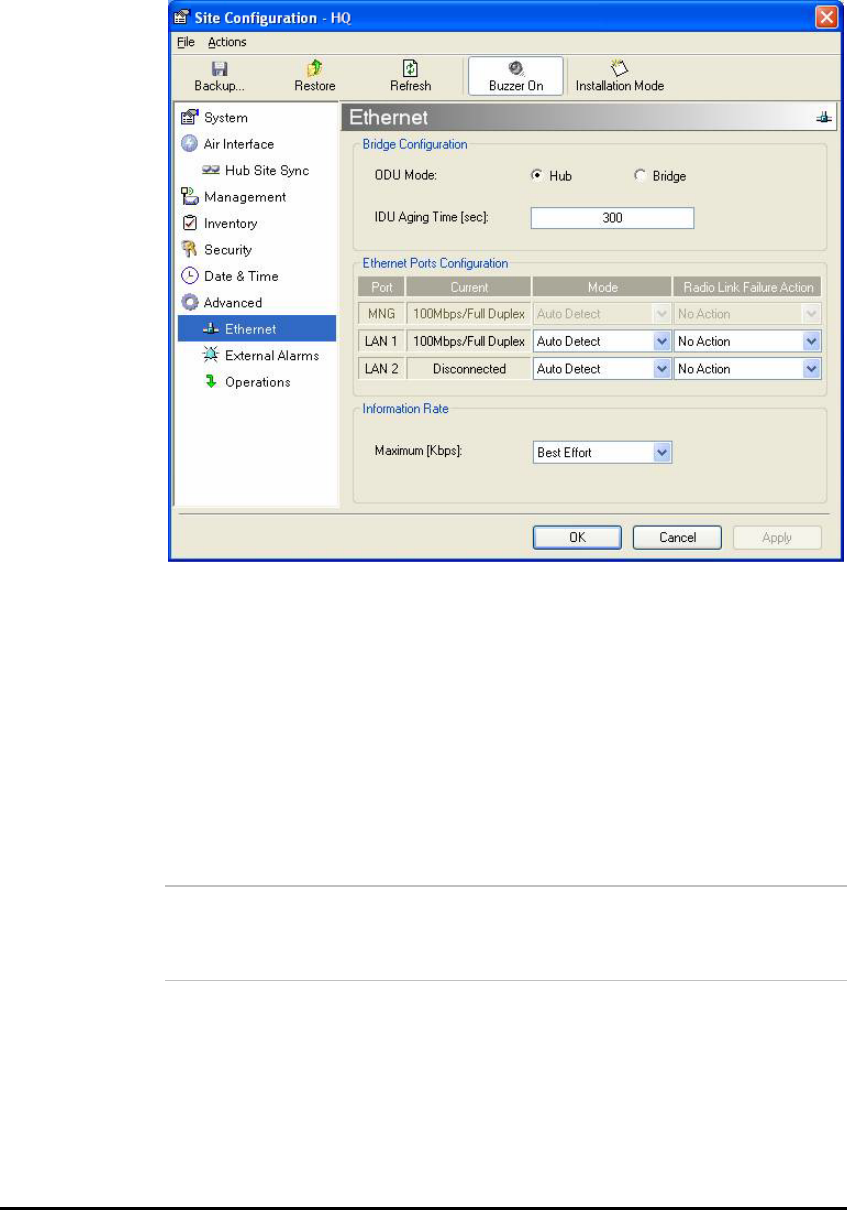
WinLink User and Installation Guide Version 1.795 5-79
parameters are located under the Advanced tab of the Configuration
dialog box:
Figure 5-17: Bridge Configuration - Site Configuration dialog box
ODU Bridge Mode
This parameter controls the ODU mode with two optional values,
• Hub Mode – in Hub mode the ODU transparently forwards the
all the packets over the wireless link.
• Bridge Mode – In Bridge mode the ODU performs both
learning and aging, the aging time of the ODU is fixed at 300
seconds.
Note:
Changing these modes requires system reset.
IDU Aging time
This parameter controls the IDU aging time.
The IDU has a 2047 MAC address-learning table. The aging time
parameter controls the time each MAC address is dropped from the
table.
Default value is 300 seconds.

WinLink User and Installation Guide Version 1.795 5-80
Note:
Any change to these parameters is effective immediately.
Each side of the link can be configured separately.
• The following list details common configurations; both sides
are must be configured with the same parameter.
• Standard (Default) Configuration for Ethernet Applications
• Set IDU aging to 300 seconds, ODU set to Bridge mode
• Fast aging mode – for rapid network topology changes
• Set IDU aging to one second, ODU set to Hub mode.
• Hub Mode
• The ODU is set to HUB mode. IDU aging is not applicable.
• Ethernet Bridge
The ODU is set to Bridge mode. The IDU aging is not applicable.
Configuring Ethernet Mode
The Ethernet mode is configurable for line speed (10/100BaseT) and
duplex mode (half or full duplex). This mode provides an Auto detect
feature where the line speed and duplex mode are detected
automatically using auto negotiation. Use the manual configuration
when external equipment does not support auto negotiation. The
default setting is Auto Detect.
The maximum Ethernet Information Rate can be limited via the pull
down menu. The default setting is Best Effort.
Note:
It is not recommended to configure the port that is used for the
management connection, since a wrong configuration can cause
management disconnection or Ethernet services interruption.
Æ To configure the Ethernet Mode:
1. From the Configuration menu, select the site to reconfigure.
The Site Configuration dialog box opens.
2. Click Advanced > Ethernet.
3. In the Ethernet Ports Configuration pane, use the drop-down menu
to select the LAN configuration.

WinLink User and Installation Guide Version 1.795 5-81
4. Click Apply to save the changes.
Note:
It is possible to close the Ethernet service by disconnecting the
Ethernet port. The user should be aware that it is possible to close the
port and not have any access to the device. If this should occur the
workaround is as follows:
• Connect the system from the remote site
• Connect via other Ethernet port (IDU-C)
• Power down the equipment and connect immediately after the
power up (the fastest way is to enter install mode).
Setting the Maximum Information Rate
The maximum Ethernet throughput of the link can be limited. The
default setting is Best Effort, where the highest information rate
available for the link conditions and settings is used.
Æ To set the Ethernet information rate:
1. From the Configuration menu, select the site to reconfigure.
2. Click Advanced > Ethernet
The Configuration dialog box opens.
3. In the Information Rate pane, use the drop-down menu to select
the maximum Information Rate.
4. Select Other to define the throughput with 8 Kbps resolution
5. Select Best Effort for the highest information rate possible for the
link conditions and settings
6. Click Apply to save the changes.
Note:
ACCESS systems have a maximum rate of 2048 kbps.
Configuring the Jitter Buffer
By configuring the Jitter Buffer, the receiver jitter buffer for each site
can be enlarged, thereby increasing system resistance to interference
(the larger the jitter buffer, the longer the interference period that the
system will overcome without TDM BER). You can also decrease the
jitter buffer to decrease the system delay.
The jitter buffer can be configured between 2.1 and 16.0 milliseconds.
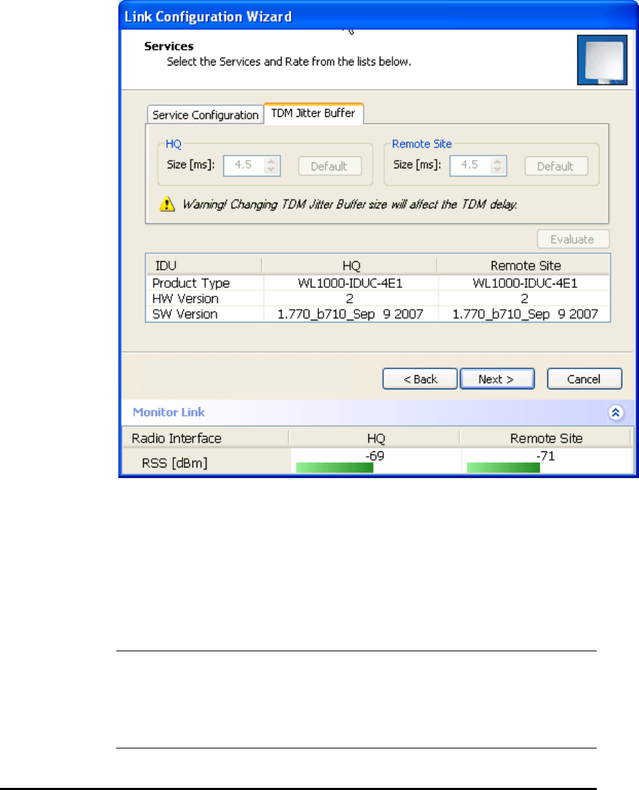
WinLink User and Installation Guide Version 1.795 5-82
Æ To configure the Jitter Buffer:
1. In the Main menu click the Link Configuration button.
2. Run the Configuration wizard (see
Figure
5-1
).
3. On the Services screen, select the TDM Jitter Buffer tab:
Figure 5-18: Jitter Buffer Configuration
4. Choose the desired values for HQ and Remote Site.
After setting the new value, the user must evaluate the expected
quality. During the evaluation the ETBE bar is displayed.
5. Click Next > to perform the change or < Back to cancel the
change.
Extra caution should be use when decreasing the value, since the
service quality might be affected in the case of interference. In cases
of asymmetric interference, the jitter buffer can be set to different
values per site. In such cases the latency will also be asymmetric.
Cautio
n

WinLink User and Installation Guide Version 1.795 5-83
Changing Community Values
The ODU communicates with the management application using
SNMPv1 protocol. The protocol defines three types of communities:
• Read-Only for retrieving information from the ODU
• Read-Write to configure and control the ODU
• Trap used by the ODU to issue traps.
The community string must be entered at login. The user must know
the password and the correct community string in order to gain access
to the system. A user may have read-only privileges.
It is not possible to manage the ODU if the read-write or the read
community values are forgotten. A new community value may be
obtained from technical support for the purpose of setting new
community; the serial number or the MAC address of the ODU must be
supplied.
Note:
The manager application and the ODU use the community strings
public-bru1 for the local unit and public-bru4097 for the remote
unit. These are the factory defaults, but can only be used one time on
the first installation.
A new community string must be set when entering the system for the
first time. The read-write community and read-only community have a
minimum of five alphanumeric characters. (Bru1 and bru4097 are not
permitted). Changing the trap community is optional by clicking the
check box.
Editing Community Strings
The community change dialog box is available from the
Configuration > Security tab. Both read-write and read-only
communities must be defined.
On entering for the first time, use the following as the current
community:
• For Read/Write community, use netman.
• For Read Only community, use public.
• For Trap community, use public-bru1.
Æ To change a community:
1. From the Configuration dialog box, select the Security tab
2. Type the current read-write community (default is netman).
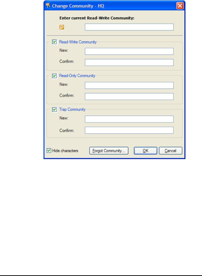
WinLink User and Installation Guide Version 1.795 5-84
3. Select the communities to be changed by clicking the check box.
4. Type the new community and re-type to confirm.
5. Click OK to save.
Figure 5-19: Changing the Community String
Forgotten Community string
If the read-write community string is unknown, an alternative
community key can be used. The alternative community key is unique
per ODU and can be used only in order to change the community
strings. The alternative community key is supplied with the product,
and it is recommended to keep it safe.
If both the read-write community and the alternative community key
are unavailable, then an alternative community key can be obtained
from customer support using the ODU serial number or MAC address.
The serial number is located on the product, and the MAC address is
displayed in the manager inventory tab.
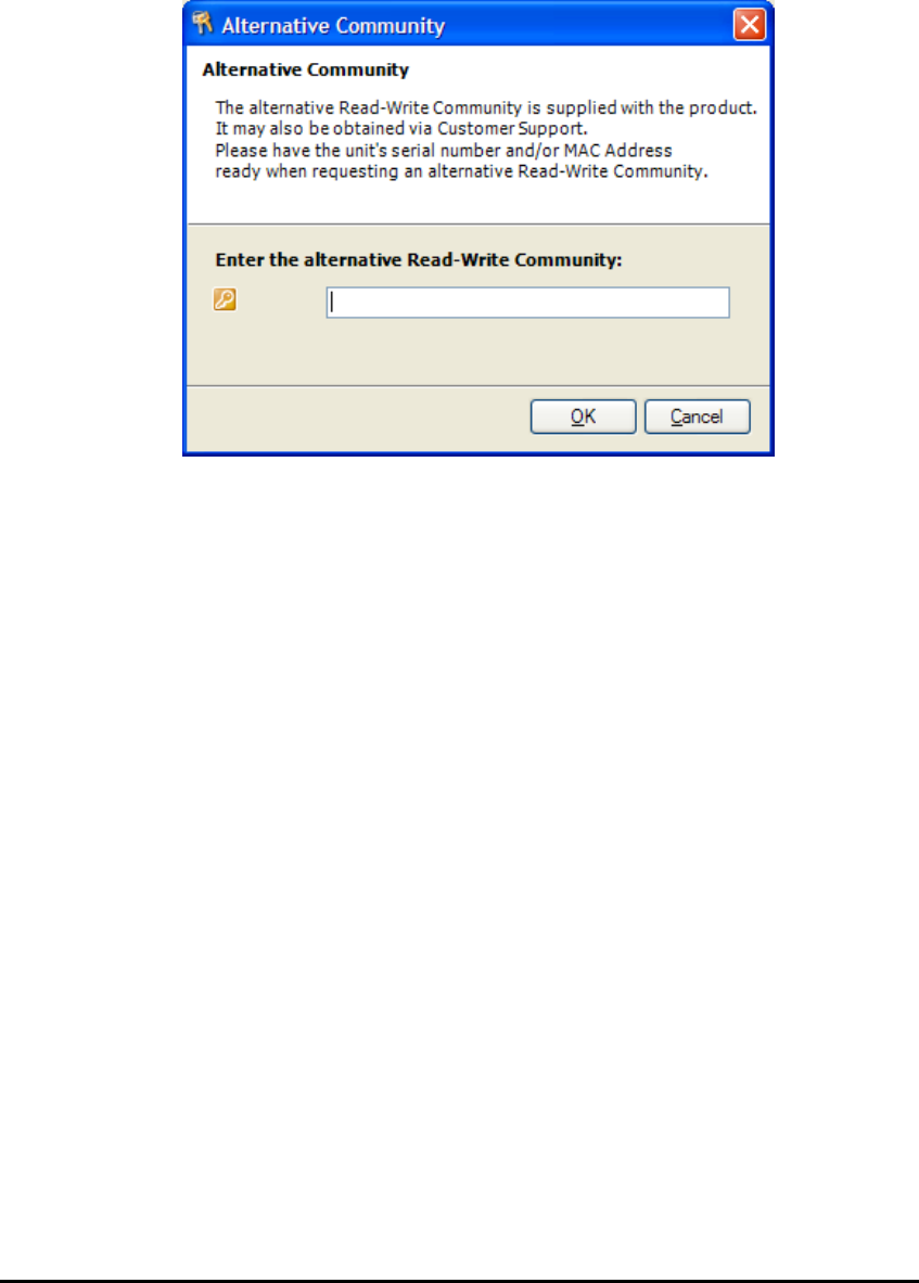
WinLink User and Installation Guide Version 1.795 5-85
When you have the alternative community key, click the Forgot
Community button and enter the Alternative Community
(
Figure
5-20
). Then reconfigure the read-write community string.
Figure 5-20: Alternative Community Dialog box
Muting the alignment tone
The ODU alignment tone becomes audible as soon as power is
supplied, and continues until the ODUs are aligned and the link
established.
It is possible to mute the tone until the alignment procedure is to be
performed.
Æ To mute the alignment tone:
1. Click on Configuration in the Menu bar and select the relevant
site.
2. The Configuration dialog box opens.
3. In the Configuration dialog box, click the Buzzer button. The button
toggles between on and off.
The tone stops.
Æ To restore the alignment tone:
1. Click Configuration in the Menu bar and select the relevant site.
The Configuration dialog box opens.
2. In the Configuration dialog box, click the Buzzer button. The button
toggles between on and off. The tone starts.
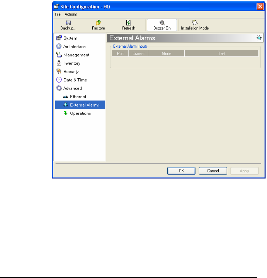
WinLink User and Installation Guide Version 1.795 5-86
Setting External Alarm Inputs
The IDU-C has two external alarm inputs in the form of dry-contact
relays. The Alarm interface is located on the front panel of the IDU-C
and is a 9-pin D-type female connector, see IDU-C Alarm Connector,
Wiring Specifications for the pinout. The user enables or disables
each of the alarms and can configure the text that appears in the
alarm trap. The ODU sends the alarm within less than a second from
actual alarm trigger.
Æ To set the external alarm inputs:
1. Open the Site Configuration Alarms configuration by clicking
Configuration > Advanced.
Figure 5-21: External Alarm Configuration
2. Enter a description of the alarms in the fields.
3. Click Apply to save.

WinLink User and Installation Guide Version 1.795 5-87
Managing Configuration Files
Saving Configuration in a File
The management software allows you to save configuration
parameters of the local and remote units on the management station
as an INI file. Each site is saved in a separate INI file.
Æ To save the configuration in a file:
1. Click Configuration from the main menu.
2. Select which site to backup.
The configuration dialog box opens.
3. Click Backup.
4. In the Save As dialog box, indicate in which folder and under what
name configuration file is to be saved, and click Save.
Restoring a Configuration File
Configuration files (*.ini) can be uploaded from the management
station. Verified configuration files can be distributed to other units
that use the same configuration.
Æ To restore a configuration file:
1. From the Configuration menu, select the site to reconfigure.
The Configuration dialog box opens.
2. Click Restore.
3. From the Open dialog box select *.ini file to upload and click OK.
Resetting
Note:
Resetting the link causes service disconnection.
In order to maintain the link configuration, reset the remote site first
.
Æ To reset the unit:
1. From Maintenance, reset the remote unit.
2. From Maintenance, reset the local unit.

WinLink User and Installation Guide Version 1.795 5-88
Æ To reset to Factory Defaults
1. Click Configuration in the Menu bar and select any one of the sites.
The Configuration dialog box opens.
2. Select Operations in the Configuration dialog box.
3. Click the Restore Defaults button.
A message box asking if you want to restore factory default
appears.
4. Click the check box if you want to keep the current IP settings.
5. Click Yes to continue.
Displaying the Inventory
Æ To view the inventory data
1. Click Configuration from the main menu.
2. Select which site to configure.
The configuration dialog box opens.
3. Select Inventory (
Figure
5-22
).
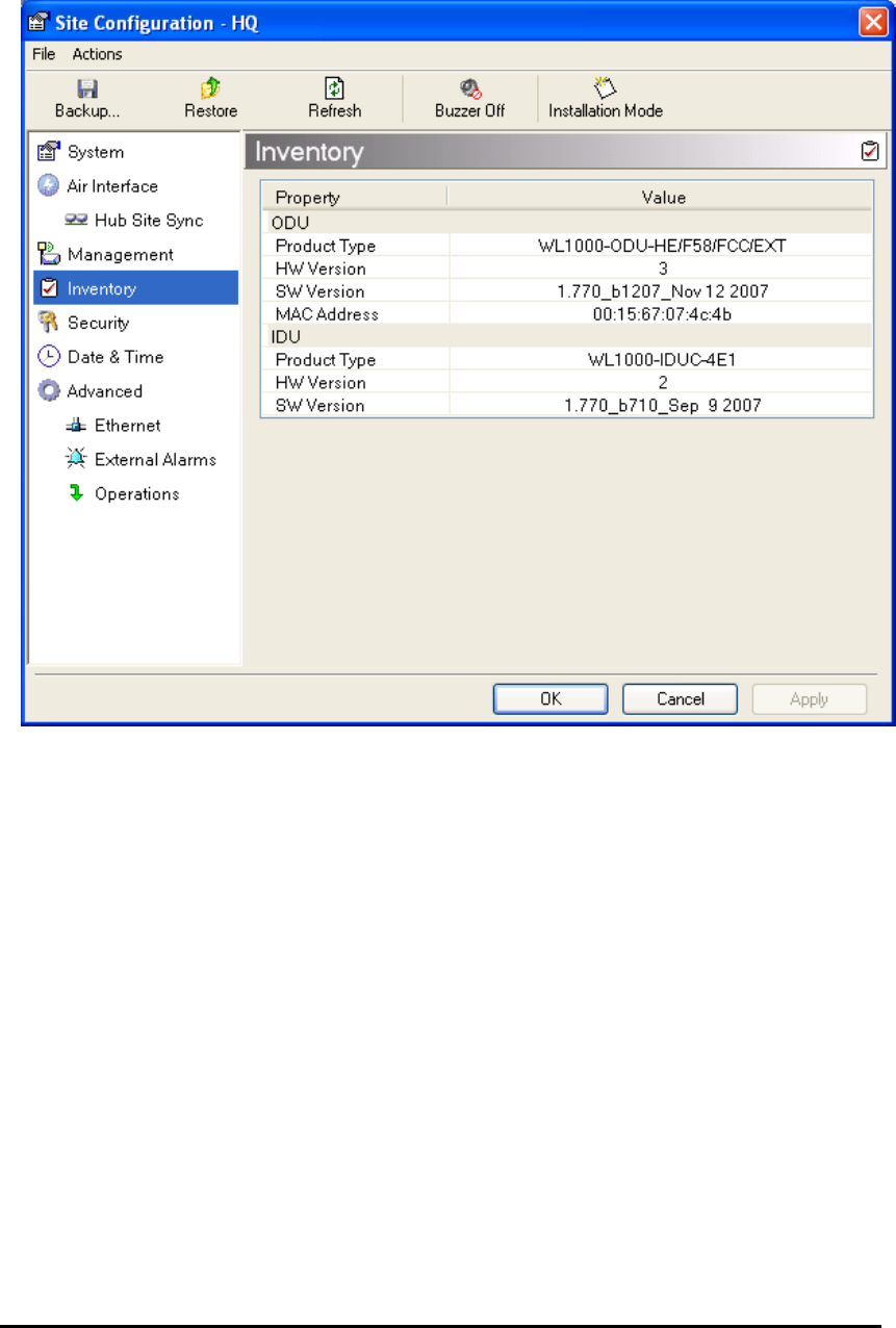
WinLink User and Installation Guide Version 1.795 5-89
Figure 5-22: Inventory Screen
Configuration via Telnet
A Telnet terminal can be used to configure and monitor the ODU.
The login username/password is identical to the communities' strings;
Read allows display only, Read/Write allows display and set
commands.
Table
5-2
depicts the Telnet commands that are supported:

WinLink User and Installation Guide Version 1.795 5-90
Table
5-2: Telnet Commands
Command Explanation
display inventory Displays ODU product name, Name, Location,
hardware and software revisions, uptime, MAC
address, IDU product name, IDU software and
hardware revisions
Display management Displays IP, Subnet, Gateway, Traps table
display link Displays State, SSID, Channel BW, RSS, TSL,
Frequency/ACS, DFS, Rate/ARA, Distance
display Ethernet Displays Bridge Mode, Aging time, Port table (State,
Status and action)
display tdm Displays Clock Mode, Master Clock Mode, Current
Clock, Quality[1], TDM table (Line status, Error
Blocks)
display ntp Displays Time, Server and Offset
set ip <ipaddr> <subnetMask>
<gateway>
Set the ODU IP address, subnet mask and gateway
The user must reset the ODU after the command
completion
display PM
<interface:AIR,LAN1,LAN2,TDM1,
TDM2,TDM3,TDM4>
<interval:current,day,month>
Shows the performance monitor tables for each
interface according to user defined monitoring
intervals
set trap <index:1-10> <ipaddr>
<port:0-65535>
Set a specific trap from the traps table (set trap 3
10.0.0.133 162)
set readpw <oldpasswd> <passwd> Set the read access password (read community)
set writepw <oldpasswd> <passwd> Set the read-write access password (read-write
community)
set trappw <oldpasswd> <passwd> Set the trap community string
set buzzer <mode:0=OFF,1 =ON> Toggle the buzzer mode (0 – off, 1 – on)
set tpc<power:Value between minimal
TX power, and maximal TX power>
Set the ODU transmit power. If a wrong value is
entered, both min and max values shall be displayed
in the error reply
set bridge <mode:0=Bridging OFF,1=
Bridging ON >
Set the ODU bridge mode (0 – off, 1 – on)
set name <new name> Set the name of the link
set location <new location> Set the name of the location
Set contact <new contact> Set the name of the site manager
set Ethernet <>port:MNG,LAN1,LAN2>
<mode:AUTO,10H,10F,100H,100F,DIS
ABLE>
Set the mode and speed of each ethernet port

WinLink User and Installation Guide Version 1.795 5-91
Command Explanation
Reboot Reset both the IDU and the ODU. The user shall be
prompt that the command will reset the card and
that he has to reconnect the telnet session after TBD
seconds.
Help Displays the available commands

WinLink User and Installation Guide Version 1.795 5-92
Figure
5-23
, below, shows the available Telnet commands via the Help
command.
Hello admin, welcome to ODU Management CLI!
+-----------------------------------------------------------+
Software Revision 1.770 Build 1115_August 13 2007
+-----------------------------------------------------------+
admin@10.103.6.1-> help
display inventory
display management
display link
display ethernet
display tdm
display ntp
display PM <interface:AIR,LAN1,LAN2,TDM1,TDM2,TDM3,TDM4>
<interval:current,day,month>
set ip <ipaddr> <subnetMask> <gateway>
set trap <index:1-10> <ipaddr> <port:0-65535>
set readpw <oldpasswd> <passwd>
set writepw <oldpasswd> <passwd>
set trappw <oldpasswd> <passwd>
set buzzer <mode:0=OFF,1 =ON>
set tpc <power:Value between minimal TX power, and maximal TX power>
set bridge <mode:0=Bridging OFF,1= Bridging ON >
set name <new name>
set location <new location>
set contact <new contact>
set Ethernet <port:MNG,LAN1,LAN2>
<mode:AUTO,10H,10F,100H,100F,DISABLE>
reboot
help
Command "help" finished OK.
Figure 5-23: Telnet Management Screen
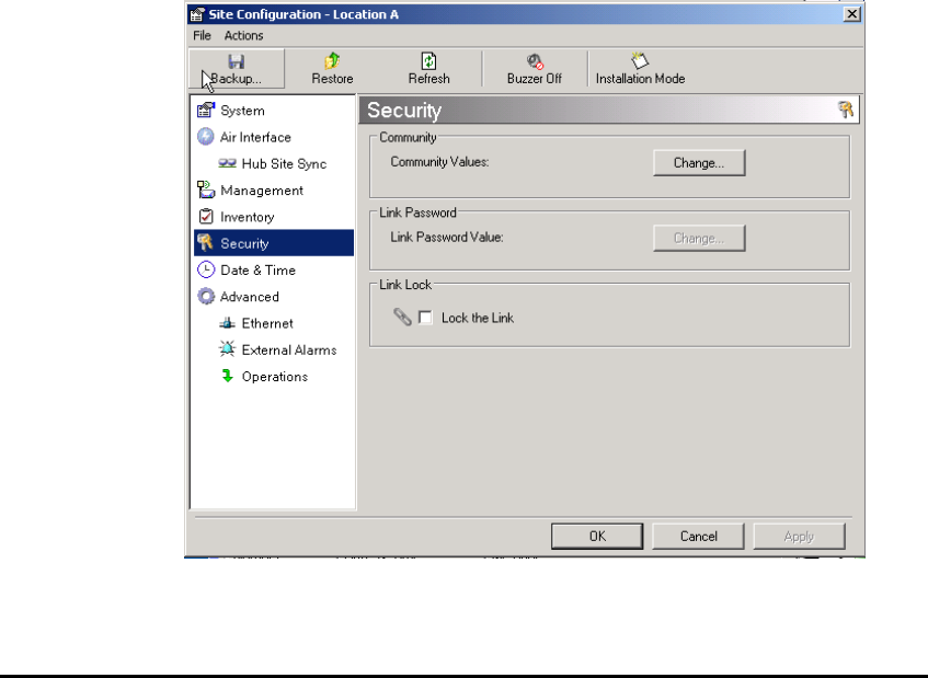
WinLink User and Installation Guide Version 1.795 5-93
Link Lock Security Feature
The purpose of Link Lock
Link Lock is a part of the WinLink security concept intended to meet a
form of abuse encountered in the field. It is designed to prevent the
situation where a remote ODU can be stolen and used as a “pirate” link
to steal services or information. The Link Lock feature actually locks
the local ODU to be synchronized ONLY to specific remote ODU. It is a
site oriented feature.
The lock can only be set from a live link. It is based on MAC
authentication and is site oriented and activated on a per ODU basis.
For example, if you lock the remote ODU to the local ODU, you must
still lock the local ODU to the remote ODU to ensure complete two way
locking.
It can only be removed when the link is unsynchronized. In such a
case, an alarm is raised by the WinLink™ 1000 Manager.
Æ To enable Link Lock:
1. From the Link Configuration menu, select “1 Configuration
Location A”.
2. Choose the Security tab. The following window is displayed:
3. Click the Link Lock checkbox and then OK. You are asked to
confirm the lock:
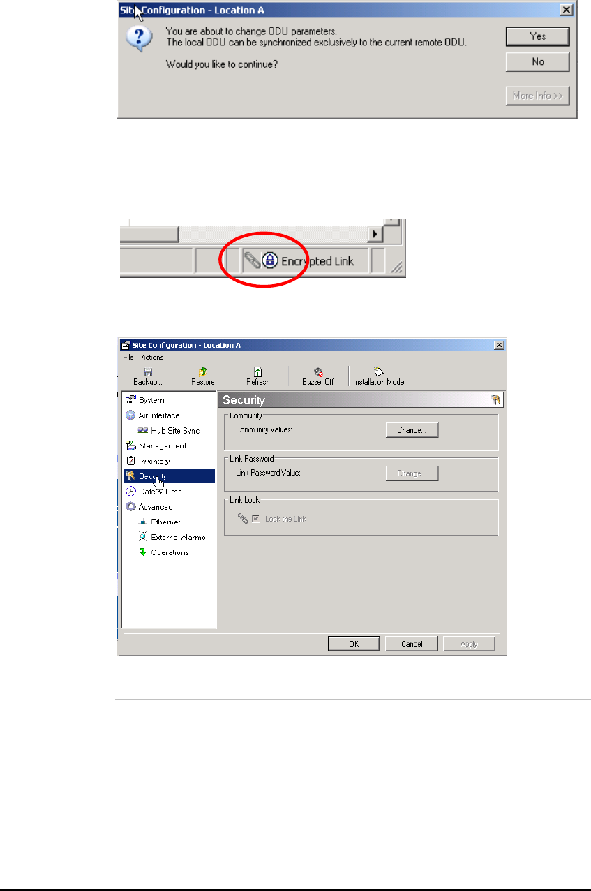
WinLink User and Installation Guide Version 1.795 5-94
4. Click the Yes button and you are returned to the main window of
the WinLink ™ 1000 Manager.
Observe that a link icon is now displayed in the status bar on the
bottom right of the WinLink™ 1000 Manager window.
The link to the remote unit is now locked. If you repeat steps 1 and 2
above, the Security screen will look like this:
The Link Lock checkbox is now unavailable.
Note:
The Link Lock status will only revert to unlocked as a result of a broken
link, for example due to an ODU being switched off at either end of the
link.
A simple ODU reset at either end will restore the link to its previous
locked or unlocked state.

Chapter 6
Monitoring and Testing
the Link
The WinLink™ 1000 Manager software enables you to monitor the link,
as well as perform Loopback tests. It also provides a handy Link
calculator utility for calculating the expected performance of the
wireless link and the possible RF and antenna configurations for a
specific link range.
Retrieving Link Information (Get Link Information)
The Get Link Information feature collects and writes all link and
Manager information (from both sides) into a comprehensive file. The
file can be used for diagnostics and should be sent to technical support
to speed up assistance.
The following table lists link and system information that can be
monitored.
Table
6-1: Get Link Information Data and Description
Æ To get link information
1. On the Help menu, choose Link Information.
Data Description
System Data General information about the system
Link Information Information about the link properties
Event Log List of recent system events
Site Configuration Data about the site parameters
Active Alarms List of active alarms
Performance Monitor Network performance data over defined time
p
eriods
Monitor Detailed event data record
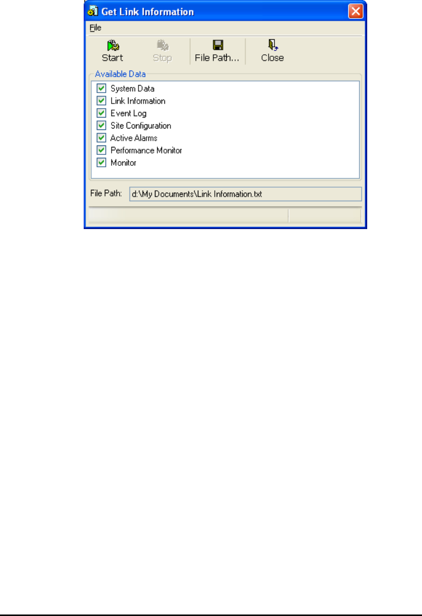
WinLink User and Installation Guide Version 1.795 6-96
The Get Link Information dialog box appears:
Figure 6-1: Get Link Information Dialog Box
2. Select or deselect the data options. If the file is to be sent to
Technical Support leave all options checked.
3. Click File Path to specify the folder in which you want to save the
file and then click Start to save the information.
The file is saved in the specified folder as Link Information.txt
Link Compatibility
Link Compatibility indicates the version compatibility via software traps.
As new hardware is added to existing networks compatibility issues
may arise. An incompatibility issue is indicated to the user via a change
of color of the Link Status box on the Main Menu screen. Trap
messages in the Event Log indicate the problems or limitations and
suggest upgrades when appropriate.
The following Link Status messages are given:
fullCompatibility - different software versions were detected that are
fully compatible. Message indicates that upgrade is available.
restrictedCompatibility - different software versions were detected that
operate correctly. However, new features are not supported
softwareUpgradeRequired - different software versions were detected
with limited operation. The link will operate as Ethernet only; a full
service will not be available. The message is software upgrade
required.

WinLink User and Installation Guide Version 1.795 6-97
versionsIncompatibility - different software versions were detected that
are not compatible. User needs to perform local upgrades.
Table
6-2: Link Compatibility Trap Messages
Link State Link Link
Status Site
Description Site Link Status
State text Color Desc.
Color Color
fullCompatibility Active Green SW
Upgrade Availa
ble
Yellow Green
restrictedCompatibility Active - SW
Version
mismatch
Magenta
(Same as
authentic
ation
error)
SW Upgrade
Recommended
Yellow Magenta
(Same as
authentication
error)
softwareUpgradeRequired Active – SW
Upgrade
Required
Brown
(Major)
SW Upgrade
Required
Yellow Brown (Major)
versionsIncompatibility Not Active -
SW
Upgrade
Required
Red Local SW
Upgrade
Required
Yellow Red
Testing the Connection
Testing the connection supports activation of the internal and external
loopbacks on the local and remote units.
Æ To activate a loopback:
1. From the Maintenance menu, choose Set Loopbacks.
The Loopbacks dialog box appears:

WinLink User and Installation Guide Version 1.795 6-98
Figure 6-2: Loopback dialog box
2. From the Local or Remote drop-down box, select a loopback that
you intend to run, and click OK.
A confirmation message appears.
3. Click OK to activate a loopback.
This activates selected loopback. A loopback status arrow in the
Main menu turns green to indicate an active loopback.
Æ To deactivate a loopback:
• From the From the Local or Remote drop-down box of the
Loopbacks dialog box, select None and click OK.
A loopback is deactivated and the corresponding status arrow
in the Main menu becomes dimmed.
Local External Loopback
Local external loopback can be set to an external loopback to test the
local E1/T1 port and its connection to the local side user equipment. In
this mode, data coming from the local user equipment is looped back
to it. This loopback is initiated from a management station connected
to the local unit.
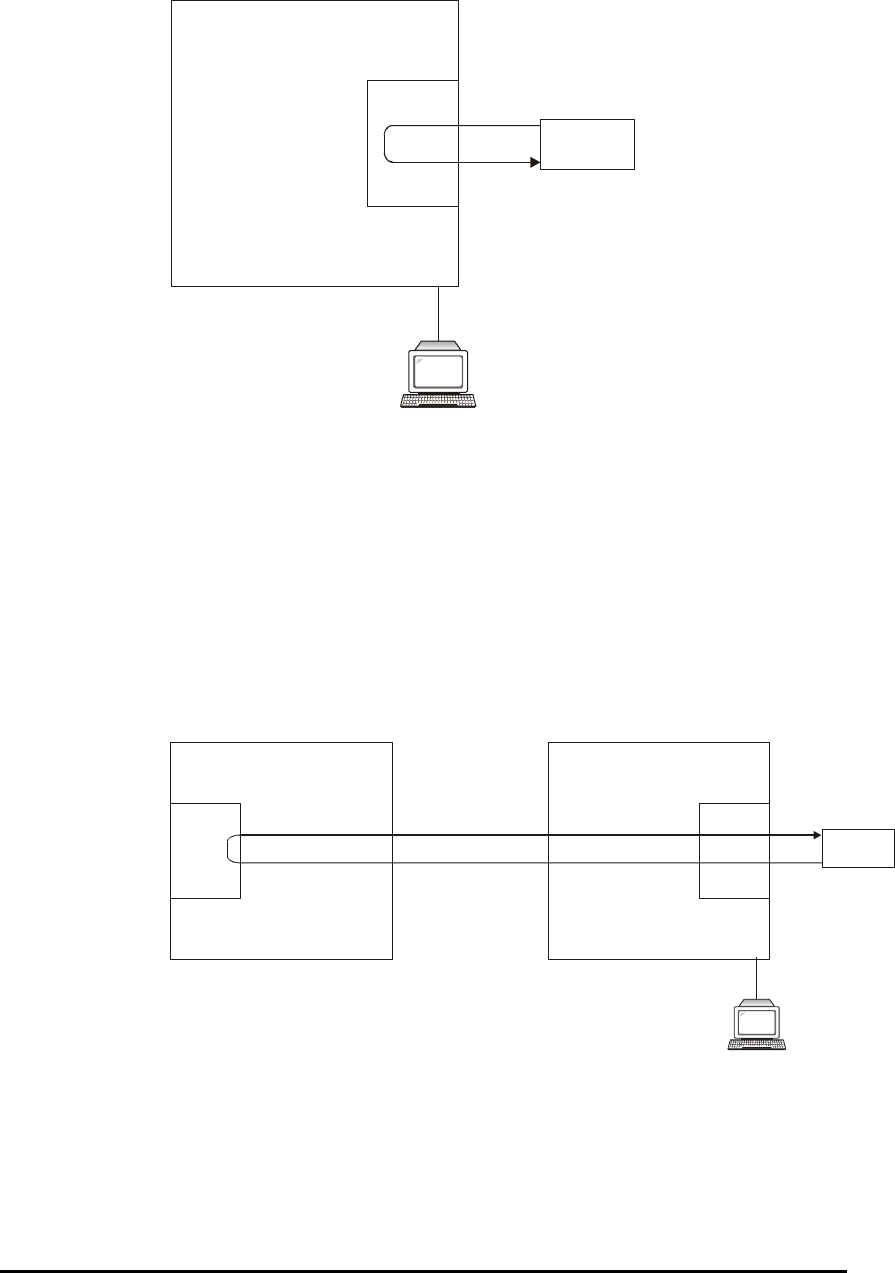
WinLink User and Installation Guide Version 1.795 6-99
Testi ng
Equipment
Management
Station
E1
Interface
/T1
Local ODU
Figure 6-3: Local External Loopback
Remote Internal Loopback
Remote internal loopback can be set to an internal loopback to test
connection between the local and remote units, the local E1/T1 port
and its connection to the local side user equipment. In this mode, data
coming from the local unit is looped back to it. This loopback is
initiated in band from a management station connected to the local
unit.
Management
Station
E1/T1
Interface E1
Interface
/T1
Testi ng
Equipment
Remote ODU Local ODU
Figure 6-4: Remote Internal Loopback
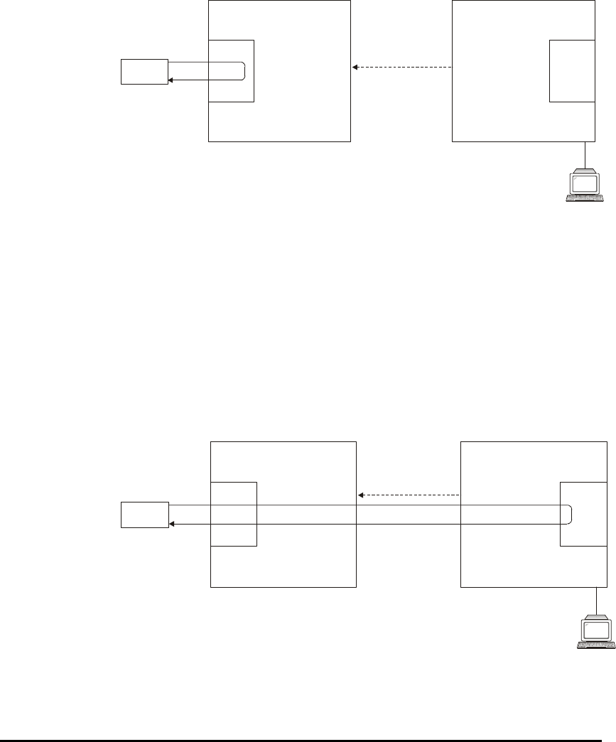
WinLink User and Installation Guide Version 1.795 6-100
Remote External Loopback
The remote unit can be set to an external loopback to test the remote
E1/T1 port and its connection to the remote side user equipment. In
this mode, data coming from the remote user equipment is looped
back to it. This loopback is initiated by an in band command sent from
a management station connected to the local unit.
Tes ti ng
Equipment
Management
Station
E1
Interface
/T1 E1
Interface
/T1
Local ODU
Inband Loopback
Activation Command
Remote ODU
Figure 6-5: Remote External Loopback
Local Internal Loopback
The local unit can be set to close an internal loopback to test
connection between the local and remote units, remote E1/T1 port and
its connection to the remote side user equipment. In this mode, data
coming from the remote user equipment is looped back to it. This
loopback is initiated by an in band command sent from a management
station connected to the local unit.
Tes ti ng
Equipment
Management
Station
Local ODU
Inband Loopback
Activation Command
Remote ODU
E1/T1
Interface E1
Interface
/T1
Figure 6-6: Local Internal Loopback

WinLink User and Installation Guide Version 1.795 6-101
Reinstalling/Realigning the Link
It may be necessary to reinstall the link if the ODUs need to be
realigned.
Note:
Activating Install Mode causes both sites to go into install mode,
causing disruption in service for approximately fifteen seconds.
Æ To reinstall the link:
1. From the Configuration menu, choose a site.
The Configuration dialog box opens.
2. In the Configuration dialog box, click the Install Mode button.
A message box asking if you want to enter install mode appears.
3. Click Yes to continue.
The system enters Install mode and the alignment tone becomes
audible.
4. Realign the ODUs and start the Installation wizard (see Chapter
3
).
The Link Budget Calculator
The Link Budget Calculator is part of the WinLink™ 1000 Manager
software and is found in the Help menu. This useful utility enables you
to calculate the expected performance of the wireless link and the
possible configurations for a specific link range including antenna size,
cable loss and climate conditions.
The Link Budget Calculator enables you to calculate the expected RSS
of the link, and determine the stability of services and their effective
throughput as a function of the link range and deployment conditions.
The Link Budget Calculator is found on the Installation CD and from
tech support so it can be used prior to installation to define and verify
link parameters such as expected RSS, maximum range, and number
of E1s/T1s that a link is capable of providing. It enables verification of
installation quality and provides calculations that consider “real world”
factors such as climate.
The Link Budget Calculator screen appears in the following figure.
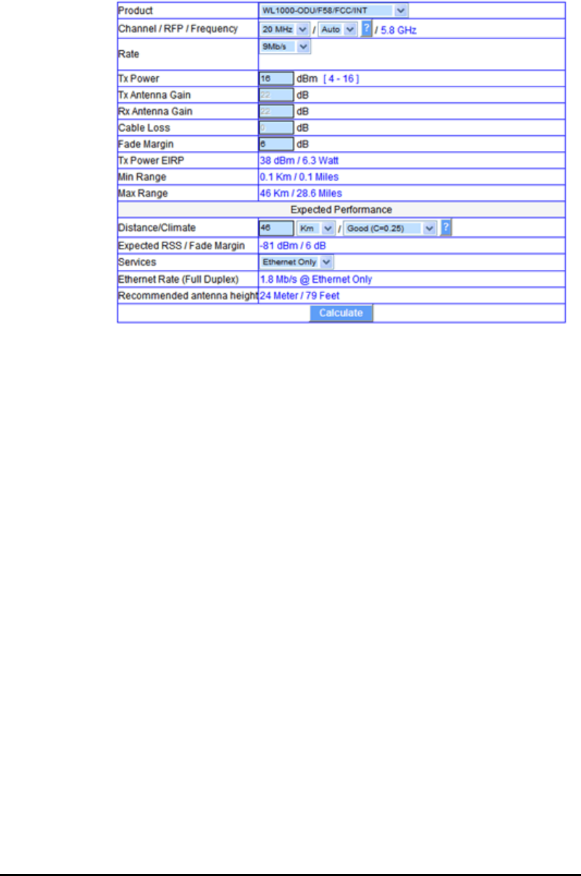
WinLink User and Installation Guide Version 1.795 6-102
Figure 6-7: WinLink™ 1000 - Link Budget Calculator
Performance Monitoring
Performance Monitoring constantly monitors traffic over the radio link
and collects the following statistics data:
• Site 1/Site 2 received traffic rate (in Mbps)
• Site 1/Site 2 received frames rate (in Mbps)
• Radio signal strength (in dBm)
• Error (Blocks).
WinLink™ 1000 monitors the Air interface, ETH ports, and TDM trunks.
It does so continuously, even when the WinLink™ 1000 Manager is not
connected.
Two types of logs are recorded:
y Monitor log that records statistics on traffic rate and radio
signal strength.
y Events log that records when the rates fall above or below a
predefined threshold.
Both the statistics (monitor) log and event log can be saved as TXT
files.
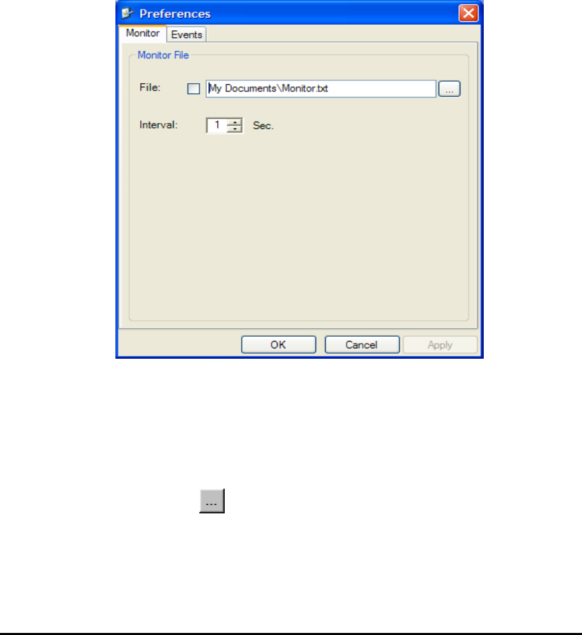
WinLink User and Installation Guide Version 1.795 6-103
The Monitor Log
The Monitor log records performance statistics for predefined intervals.
You can save the monitor log to a text file, as well as display the
information in an on-screen report.
Saving the Monitor Log
You can save the recorded Monitor log statistics to a text file.
Æ To save the monitor log:
1. From the Tools menu, choose Preferences.
The Preferences dialog box appears:
Figure 6-8: Preferences dialog box
2. Click the Monitor Tab.
3. Select the file to save.
4. Click the check box to open the file for saving.
5. Click the button and in the Select File dialog box indicate in
which folder and under what name the monitor log file is to be
saved.
6. Set the time interval for adding data to the file.
7. Click OK to save the file.
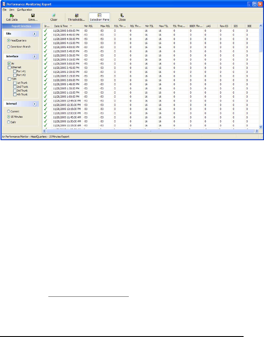
WinLink User and Installation Guide Version 1.795 6-104
Viewing Performance Reports
The Performance Monitor Report displays performance views of each
of the interfaces3:
Figure 6-9: Performance Monitoring Report window
Several performance data occurrences are collected for each of the
interfaces (ES, SES, and UAS), as well as Specific data per Interface
type (e.g., TX and RX bytes for Ethernet). For the Air Interface, user
defined thresholds data are collected. Refer to
3 Ethernet performance is not collected in PoE systems.

WinLink User and Installation Guide Version 1.795 6-105
Table
6-3
and
Table
6-4, Performance Monitoring Report Toolbar.
Data is collected and selectively displayed based on three time
intervals as selected by the Interval radio buttons:
• Current (t=0)
• 15 minutes Intervals
• Daily.
UAS – This parameter counts the time the air link was not providing
any service. There are several potential reasons for this situation; one
of the sites has a power failure, high interference, maintenance
operation, etc.
Radio BBER Threshold – This parameter counts the seconds in which
the radio performance is below a user specified threshold. The
threshold is measured in percent. The threshold can be set from 0.1%
up to 50%.
For links with E1/T1 service the recommended value is 1% (system
default). Excellent TDM service is expected below the 1% threshold,
meaning that for 1% threshold, the expected BBER value should be 0
if there are no problems during the 15 min interval. If the BBER
threshold increases a degraded service might be noticed.
For links with Ethernet only service, 8% threshold is recommended and
not 1% meaning that for 8% threshold, the recommended BBER value
should be 0 if there are no problems during the 15 min interval. Since
the system provides a loss less Ethernet service, there is throughput
degradation in case of interference. The degradation is proportional to
the BBER.
Radio RSS Threshold - Radio RSS Threshold can also be used to
indicate problems in the radio channel. You can verify the RSS
according to the link budget calculator during the installation. A value
of -5dB from the current RSS is recommended as a threshold.

WinLink User and Installation Guide Version 1.795 6-106
Table
6-3: Explanation of performance data
Data type Reported Value Explanation
UAS – Unavailable
Seconds
Seconds in which the interface was out
of service.
ES – Error Second The number of seconds in which there
was at least an error block. Note that
notation of an error block is different per
interface.
SES – Severe Error
Second
The number of seconds in which the
service quality is low (the actual BBER
ratio varies per interface).
BBE – Background
Block Error
The number of error block in an interval.
Generic PM Data
Integrity A flag indicating that the data is valid.
Note that the PM data is not valid if not
all the values were stored4.
Max RSL The maximum of the receive signal level
(measured in dBm).
Min RSL The minimum of the receive signal level
(measured in dBm).
Max TSL The maximum of the transmit signal
level (measured in dBm)5.
Min TSL The minimum of the transmit signal level
(measured in dBm).
RSL Threshold 1 This parameter counts the number of
seconds in which the RSL is below the
specified threshold.
RSL Threshold 2 This parameter counts the number of
seconds in which the RSL is below the
specified threshold.
Air Interface PM Data
TSL Threshold 1 This parameter counts the number of
seconds in which the RSL is above the
specified threshold.
4 Possible reasons are: Clock changes within the interval and Power up
reset
5 The transmit power is fixed. The value can be changed only by user
configuration

WinLink User and Installation Guide Version 1.795 6-107
Data type Reported Value Explanation
BBER Threshold The BBER Threshold value counts the
number of seconds in which the
Background Block Error Ratio (BBER)
exceeds the specified threshold. Note,
that the system is design for excellent
quality of service with BBER of less then
1%. (at 1% BBER expected TDM BER is
less than 1E-6.
Received Bytes The number of Mega bytes received in
the specified port within the interval
Ethernet Interface PM
Data
Transmitted Bytes The number of Mega bytes transmitted
in the specified port within the interval.
Performance Monitoring Report Toolbar
You can use the toolbar to perform the actions described in the
following table:
Table
6-4: Action of the toolbar buttons
Command Button Action
Save Saves the alarms in CSV or text format for further analysis.
Refresh Reads the alarms from the ODU, and displays the alarms.
Site Selects site for the active alarms.
Close Closes the active alarm window.
Setting Air Interface Thresholds
You use the Thresholds button on the Monitoring Performance Report
toolbar to set the Air Interface Thresholds:

WinLink User and Installation Guide Version 1.795 6-108
Figure 6-10: Threshold configuration dialog box
The Events Log
The Events log records system failures, loss of synchronization, loss of
signal, and other events as described in the following table:

WinLink User and Installation Guide Version 1.795 6-109
Table
6-5: Alarms and Information Messages
Message Description
Radio Link – Sync Radio link is synchronized
Radio Link – Out Of Sync Radio link lost synchronization
Link Has Been Reset ODU was reset due to internal problem
TDM Interface – Normal TDM interface is operating properly
TDM Interface – LOS Loss of Signal is reported by TDM interface
TDM Interface – AIS Alarm Indication Signal is reported by TDM interface
TDM Interface – Loopback A loopback is active on TDM interface
Link Resetting Wireless link reset from the management station. This
alarm is caused by automatic reset after link configuration.
Local ODU Resetting The local ODU reset from the management station.
Monitor was stopped since no
connection to the link
No ODU-to-IDU traffic was detected during the last 20
minutes.
TDM Service – Normal TDM service is operating properly
TDM Service – Alarm Error has been detected on a TDM line
Configuration problem detected The link needs to be reinstalled
Channel Scanning in progress The ODU is scanning the channels for the remote ODU
Transmitting on <frequency> GHz The ODU is transmitting on the frequency channel listed
Radar activity was detected in
<site>, on channel <frequency>
GHz
For DFS versions only. Radar is detected; the channel is
prohibited for 30 minutes.
Monitoring fo Radar activity on
channel <frequency> GHz
For DFS versions only. ODU is looking for Radar activity.
Bit Failed indication Indicates ODU hardware problem. Send error code to
Technical Support.
Link Status Indicates incorrect connection or incompatibility between
versions. Available in 1.620 versions and above.
Site Status Indicates incorrect connection or operation at the site.
Available in 1.620 versions and above.
The events are displayed in the Events log in the lower part of the
WinLink™ 1000 Manager Main menu:
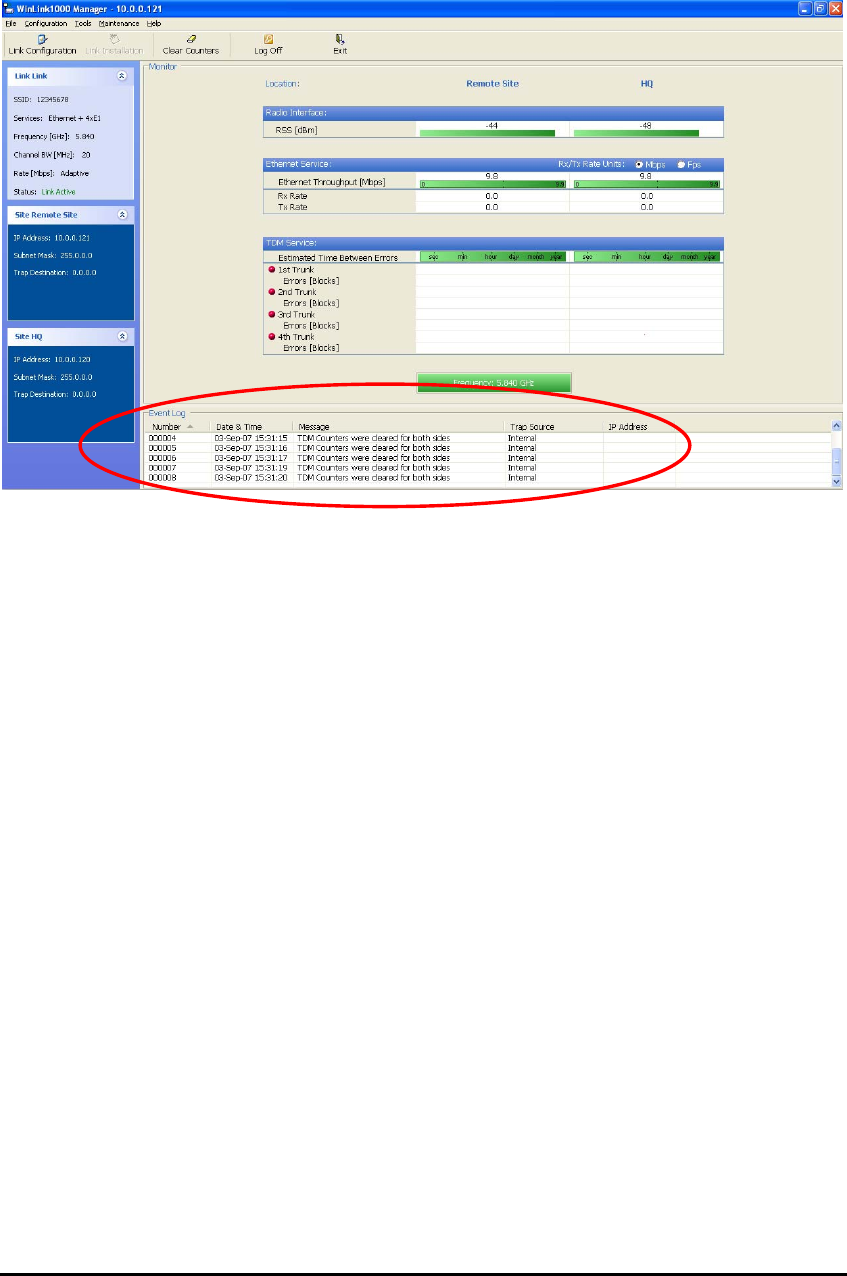
WinLink User and Installation Guide Version 1.795 6-110
Figure 6-11: Events Log Display
Setting the Events Preferences
You can define a color for the traps to be displayed in the Active
Alarms screen, according to the severity of the event. The severity is
predefined.
To set the trap color:
1. From the Tools menu, choose Preferences.
The Preferences dialog box appears.
2. Click the Events Tab:
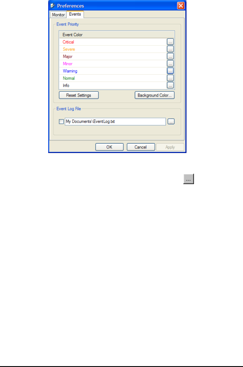
WinLink User and Installation Guide Version 1.795 6-111
Figure 6-12: Preferences dialog box
3. Select the Event priority type and click on the button.
A color chart opens.
4. Select the desired color.
5. Repeat for all the trap types.
Æ To set the trap background color:
• Click Background Color to change the text background.
Æ To reset the trap colors:
• Click Reset Settings to return to the default color settings.
Saving the Events Log
You can save recorded events in an Events log text file. New alarms
are automatically added to the text file, as they enter the event log.
Æ To save the event log:
1. From the Tools menu, choose Preferences.
The Preferences dialog box appears
2. Click the Events Tab.
3. Select the file to save.

WinLink User and Installation Guide Version 1.795 6-112
4. Click the check box to open the file for saving.
5. Click the button and in the Select File dialog box indicate in
which folder and under what name the alarm log file is to be
saved, and click OK.
Error Detection and Alarms
WinLink™ Error detection and Alarms detect compatibility problems,
fault conditions of the radio or user links, and subsequently initiates
alarms to alert the user.
Note:
To store the Event Log, first define the IP address, subnet mask,
default gateway and trap address of the management PC,
(see
Defining the Management Addresses, page 5-74 for details).
Alarms (traps) are displayed in the Event Log in the lower panel of the
Main Menu screen. The event log may be saved as a TXT file.
The event log includes the following fields:
• Sequential number (ID)
• Date and time stamp
• Message
• Trap source
• IP address of the ODU that initiated alarm.
Æ To view summary of saved alarms
• From the Tools menu, choose Active Alarm Summary.
The Active Alarms Summary window opens:
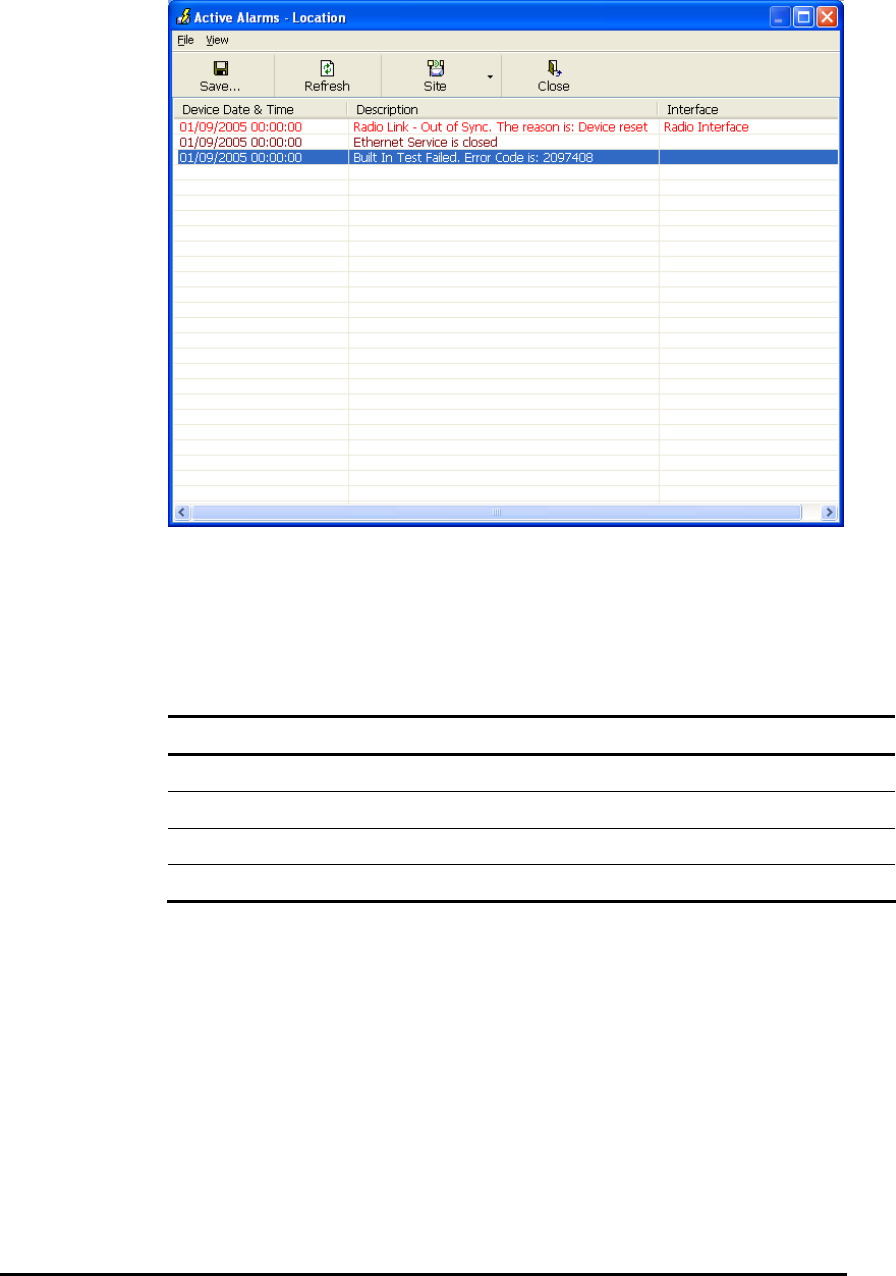
WinLink User and Installation Guide Version 1.795 6-113
Figure 6-13: Active Alarms Summary
The following table provides an explanation of the command
buttons.
Table
6-6: Active Alarms command buttons
Action
Save Saves the alarms in CSV or text format for further analysis.
Refresh Reads the alarms from the ODU, and displays the alarms.
Site Selects site for the active alarms.
Close Closes the active alarm window.
Remote Power Fail Indication
Remote power fail indication indicates to one side that the other side
has had a power failure. The failed site sends a final trap indication
about the power loss just before powering off.
A Dying-Gasp circuit identifies the power failure at a minimum interval
of 20 milliseconds before the IDU crash, during that interval a message
notifying the power failure is sent to the remote end.
Alarm output number 4 indicates link loss due to power failure at the
remote end.

Chapter 7
Security
WinLink™ 1000’s integrated advanced encryption support provides
enhanced air interface security for carriers and private networks by
ensuring user data protection with one of the most sophisticated
commercially available combined encryption and authentication
techniques, CCM/AES. This technique combines message
authentication (preventing anti-spoofing and replay protection) with
commercial encryption, and complies with the IEEE 802.11i (phase iii)
security recommendations.
CCM/AES uses a symmetric 128-bit encryption key (EK), and a nonce,
and provides both message encryption and authenticating signature.
The nonce mechanism enables the receiver to remember already
received genuine messages and reject all replayed messages.
Initial encryption and authentication is based on a user-defined master
key (Link Password). While standard Wireless LAN encrypts only the
Ethernet Payload, the AES encrypts both the source and destination
MAC addresses.
Entering and Changing Passwords
There are two passwords necessary to use the WinLink system:
• Management Password required for running the Management
software
• Link Password used for encryption purposes. This link
password is entered when installing or configuring the link.
Changing the Management Password
Æ To change the management password
1. From the Tools menu, select Change Password.
The Change Password dialog box appears.
2. Enter the current password, and the new password.
3. Click OK to confirm.