Radwin AMWL1580 Point to Point Broadband Radio System User Manual WinLink1000
Radwin Ltd. Point to Point Broadband Radio System WinLink1000
UserManual.wiki
>
Radwin
>
AMWL1580 User Manual
>
User Manual 1
Contents
1.
User Manual 1
2.
User Manual 2
User Manual 1
Navigation menu
Upload a User Manual
Namespaces
Wiki Guide
HTML
PDF
Info
Views
User Manual
Discussion / Help
Navigation
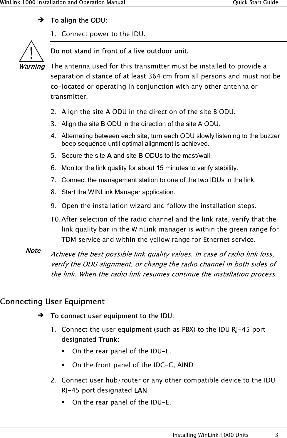
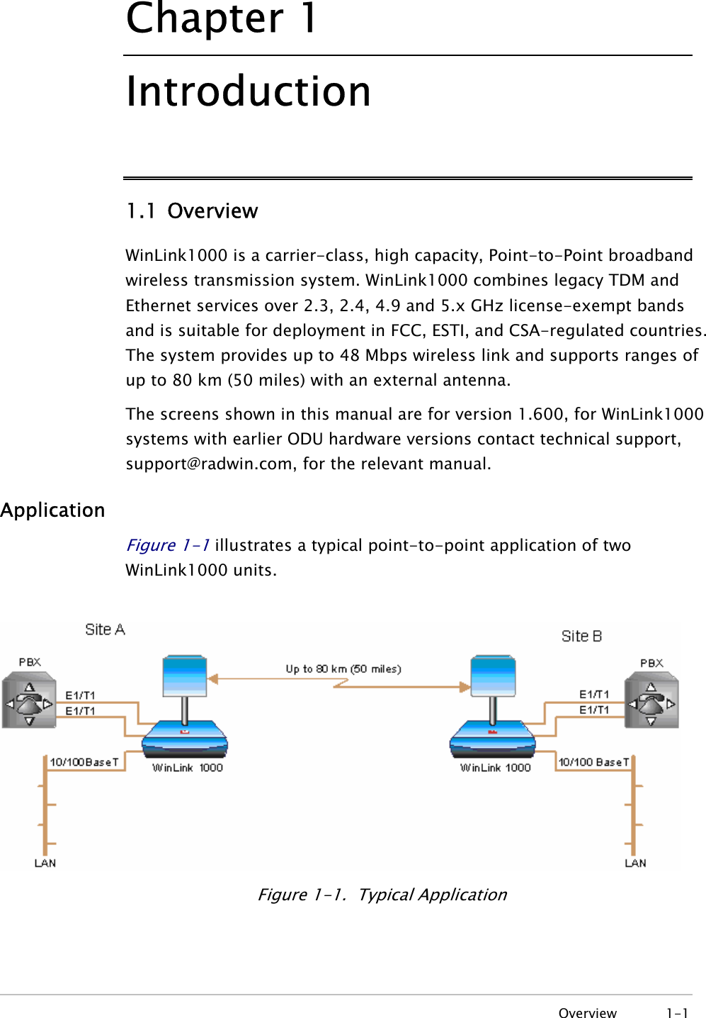
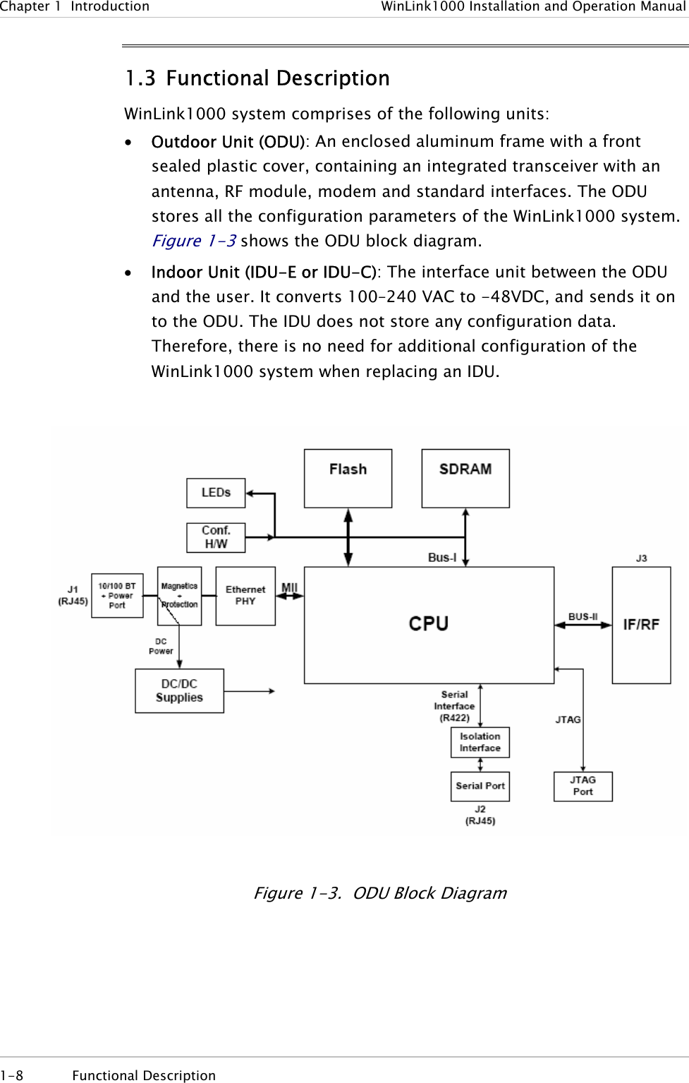
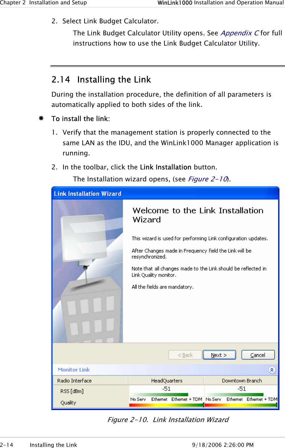
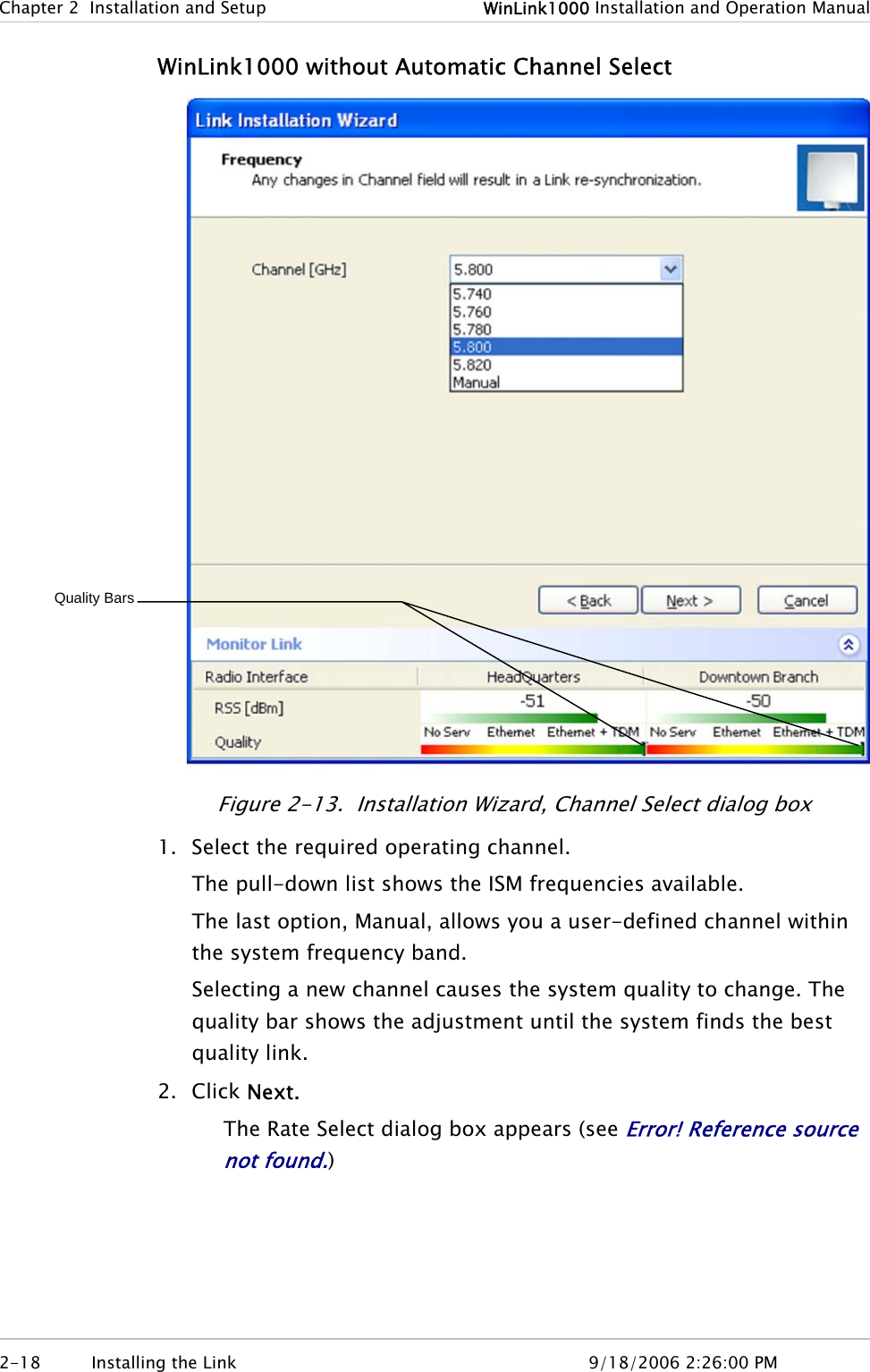
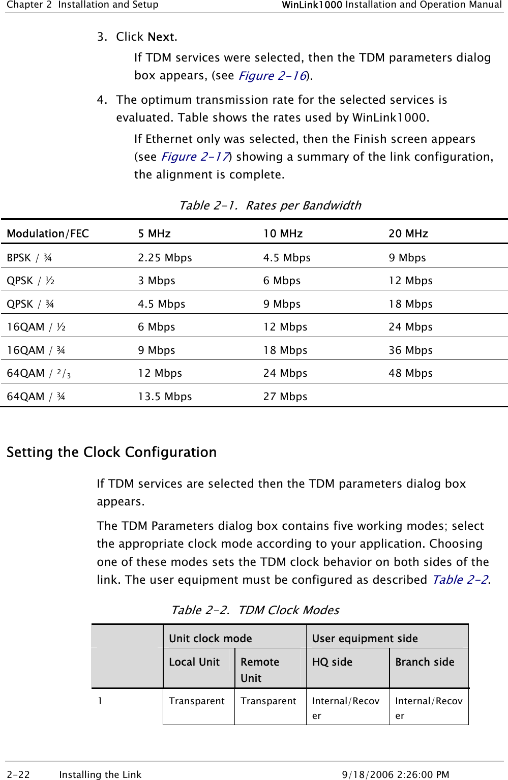
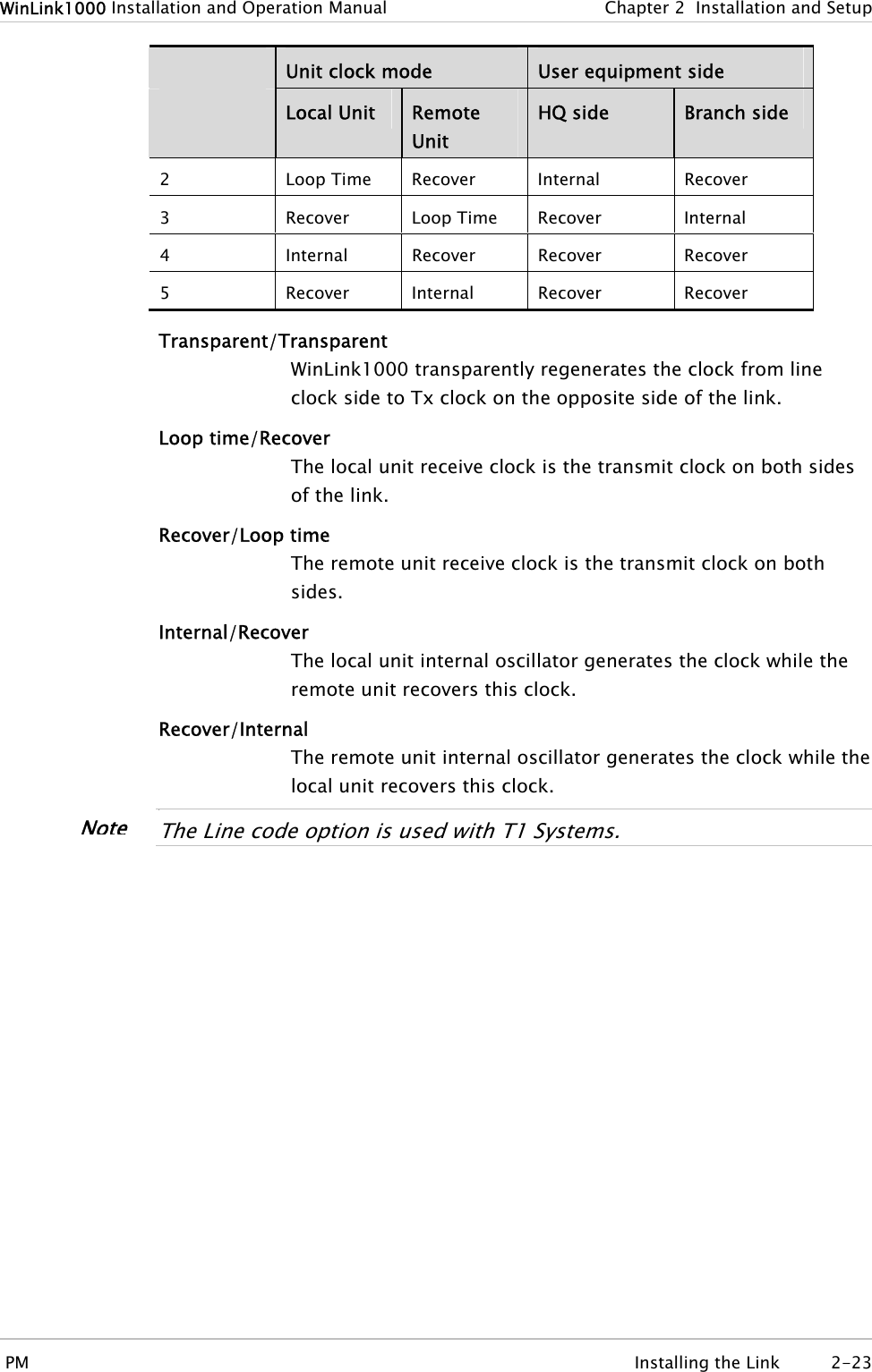
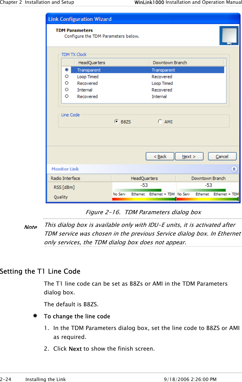
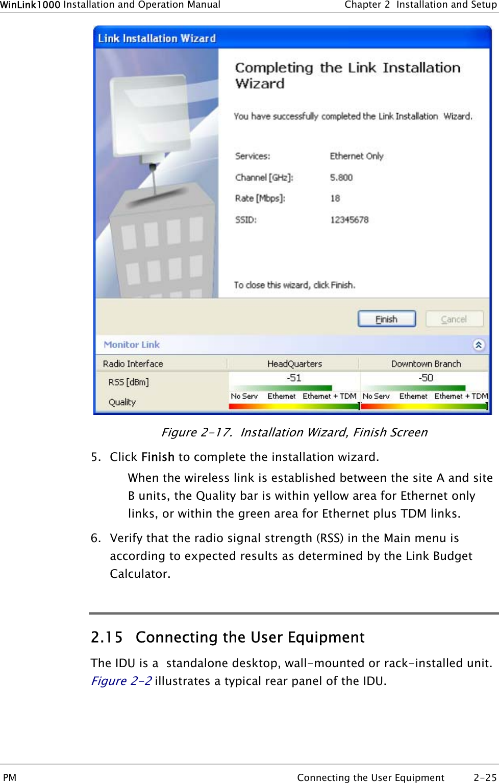
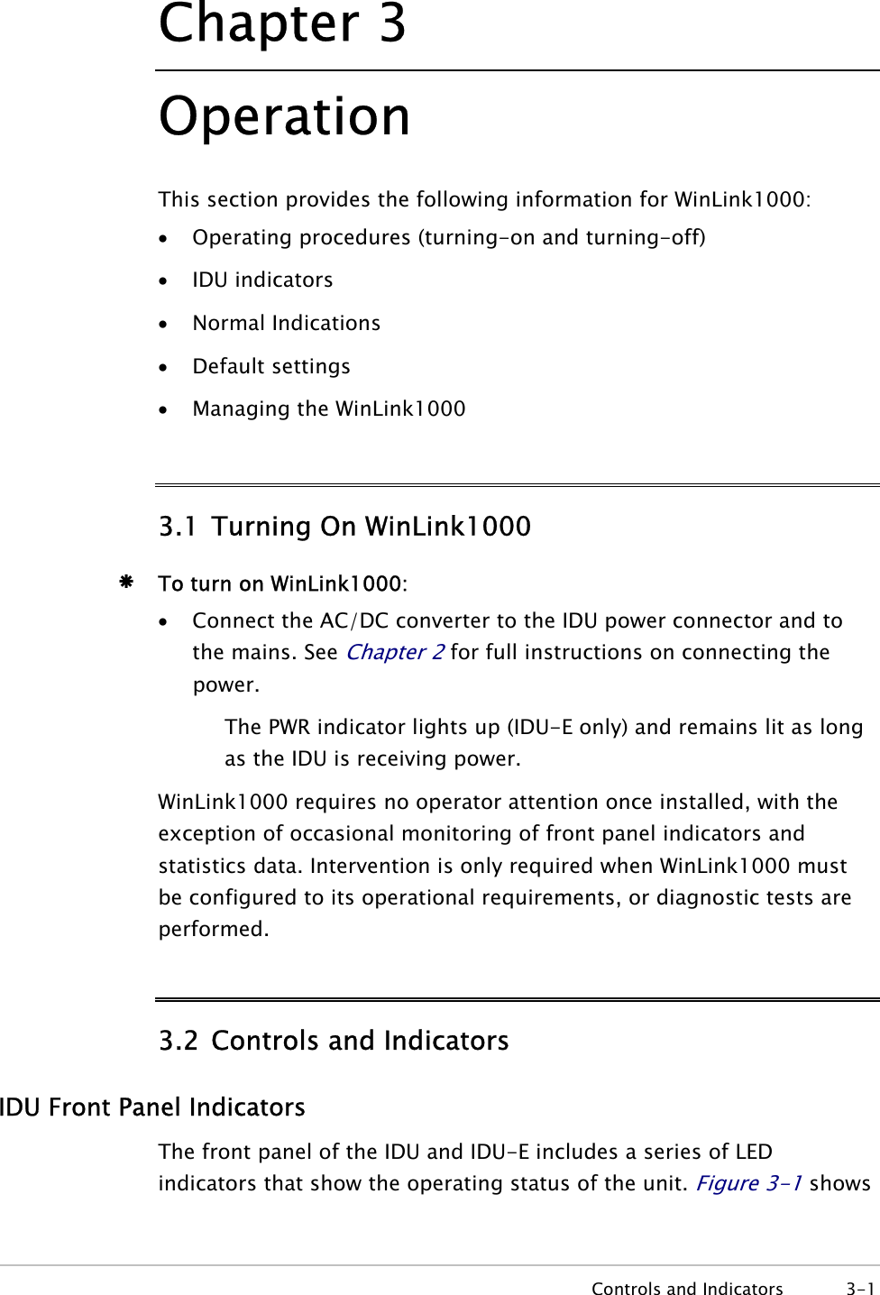
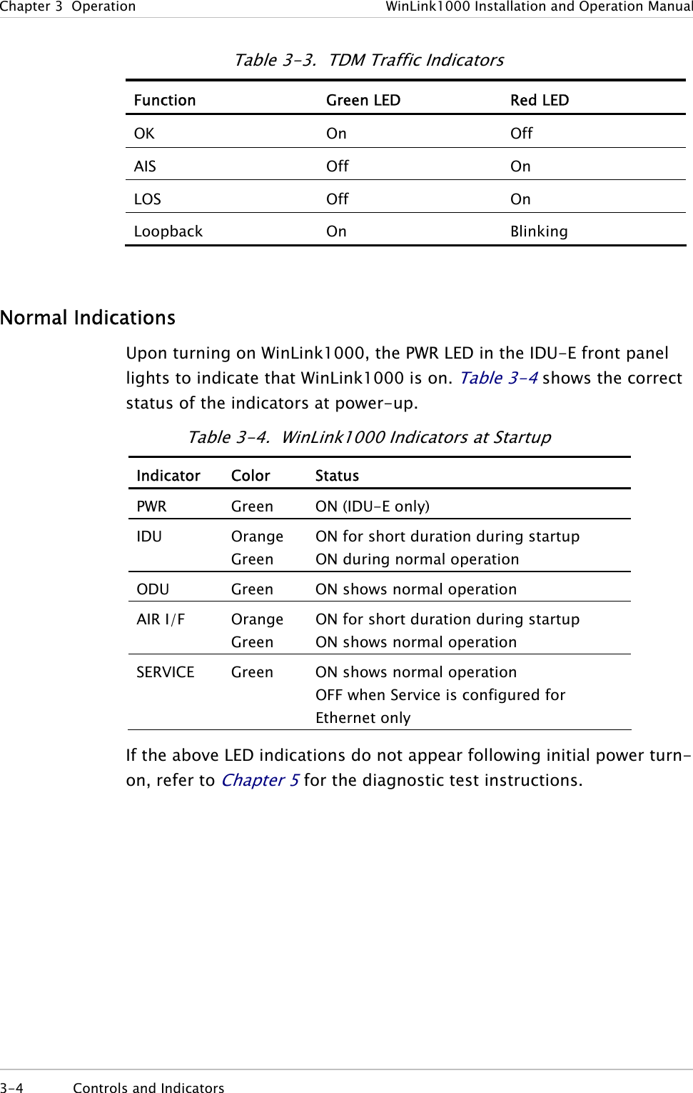
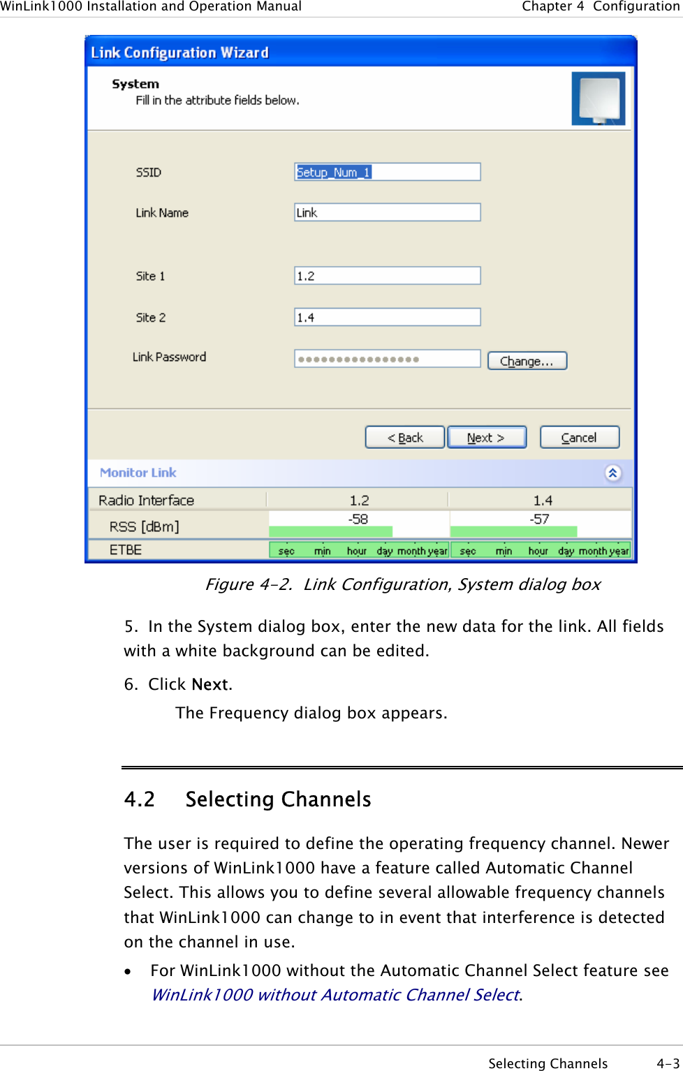
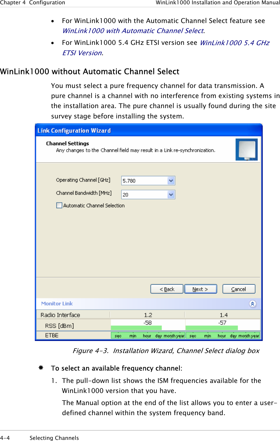
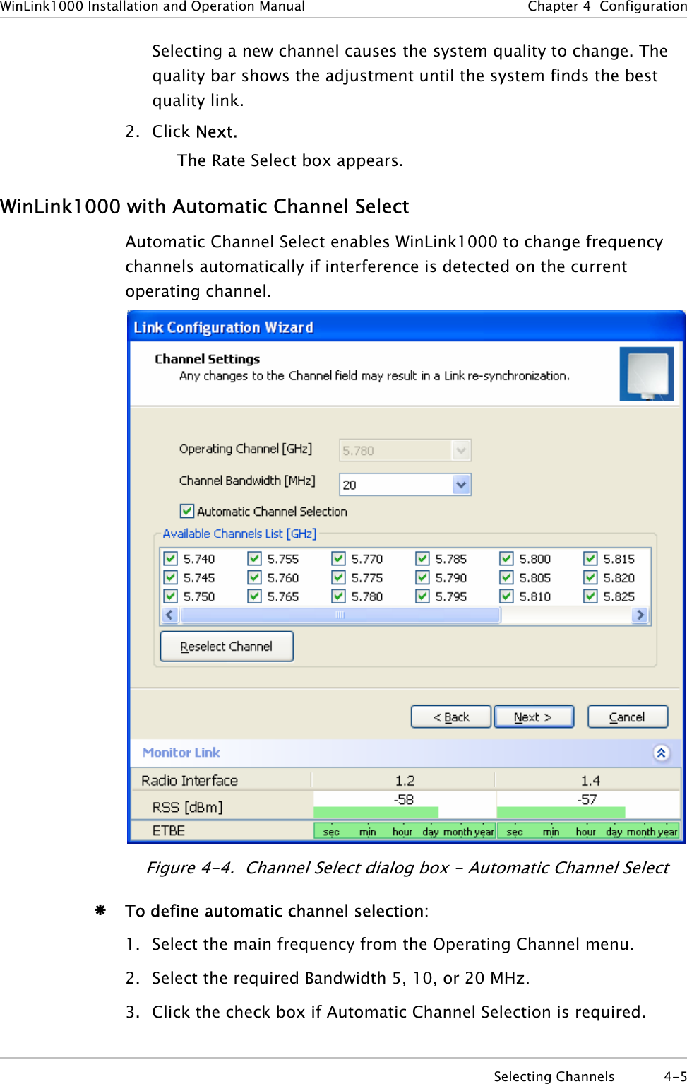
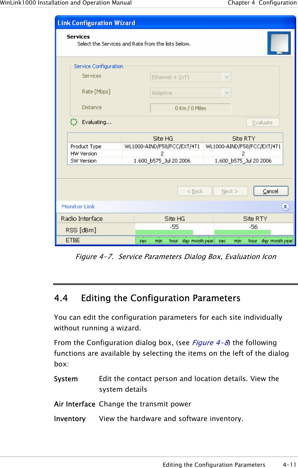
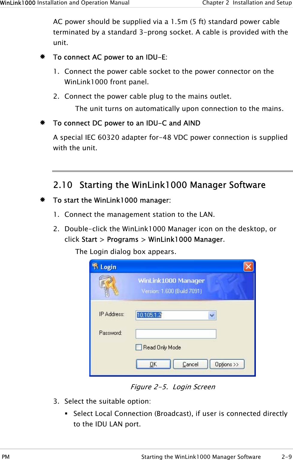
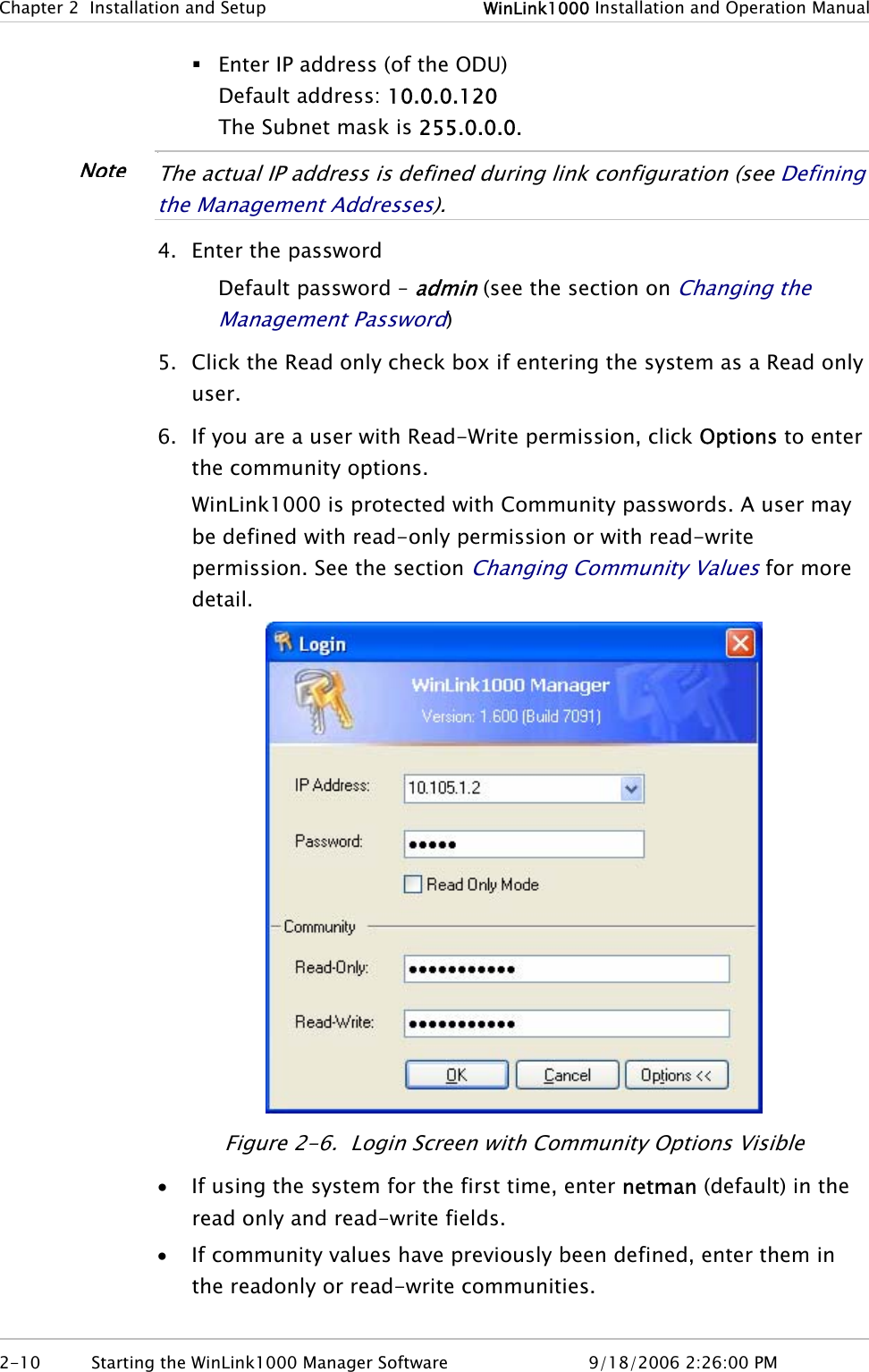
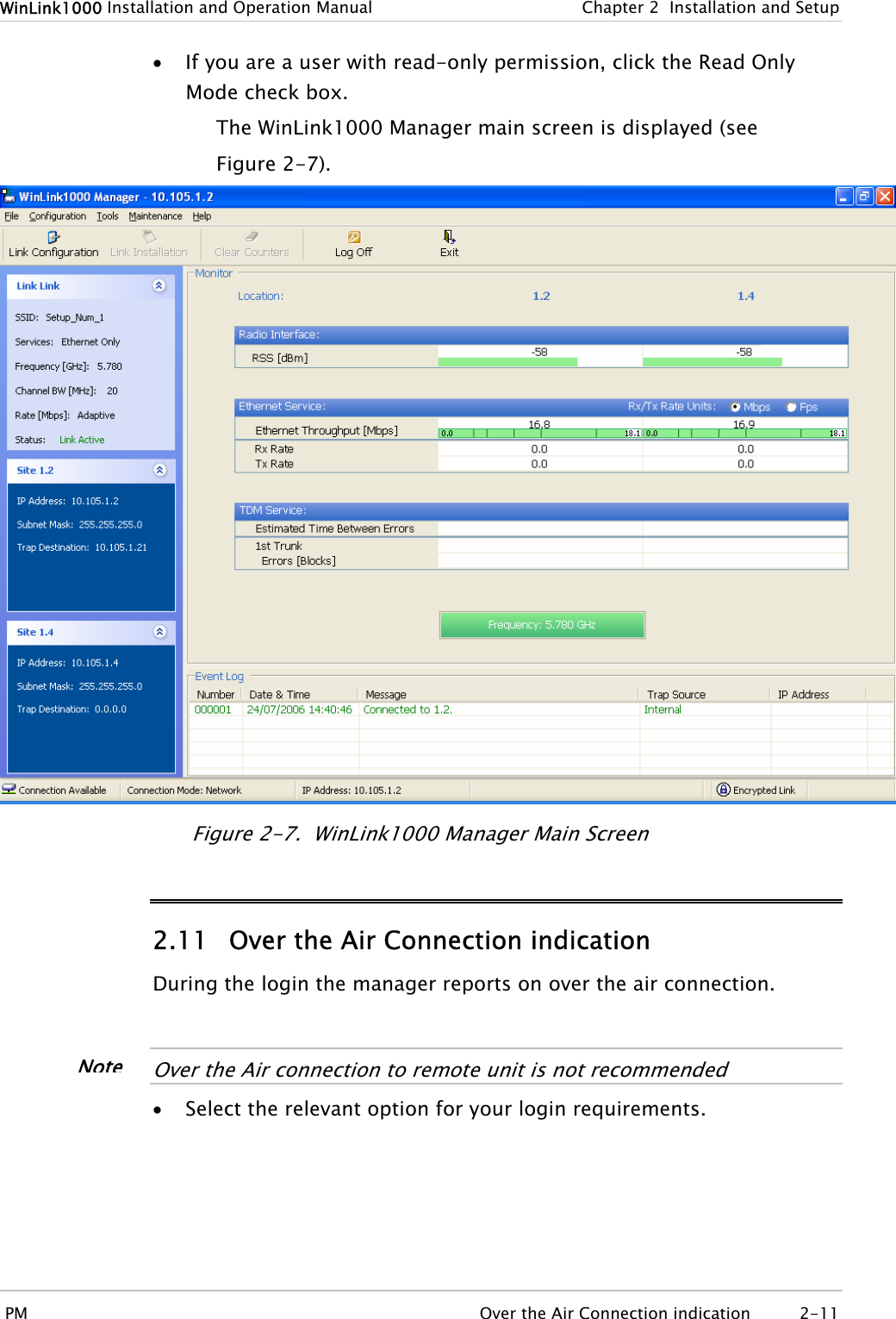
![WinLink1000 Installation and Operation Manual Chapter 1 Introduction 1.4 Technical Specifications Air Interface Technology OFDM Duplexing Method Time Division Duplex (TDD) Capacity Configurable up to 48 Mbps Modulation OFDM - BPSK, QPSK, 16QAM, 64QAM Channel Resolution 5 MHz Transmitter Power Specification is different per product, for further details refer to the Link Budget Calculator Range Up to 41 km (25.5 miles) Up to 80 km (50 miles) with an external antenna. Frequency Band [GHz] 2.300–2.483 4.940– 4.990 5.150–5.350 5.470– 5.725 5.725–5.850 Standard FCC ETSI FCC FCC ETSI FCC Antennas (See Antenna Characteristics in Appendix E) LAN Interface PHY Up to 2 × 10/100BaseT, auto-sensing Framing/Coding IEEE 802.3/U Bridging Self-learning, up to 2048 MAC addresses Line Impedance 100Ω VLAN Support Transparent Frame Size 1536 bytes max Connector RJ-45 E1 Interface Data Rate Unframed (transparent) 2.048 MHz (Specification may be different per ordering option) Line Interface HDB3 Connector RJ-45 Technical Specifications 1-9](https://usermanual.wiki/Radwin/AMWL1580.User-Manual-1/User-Guide-719234-Page-21.png)
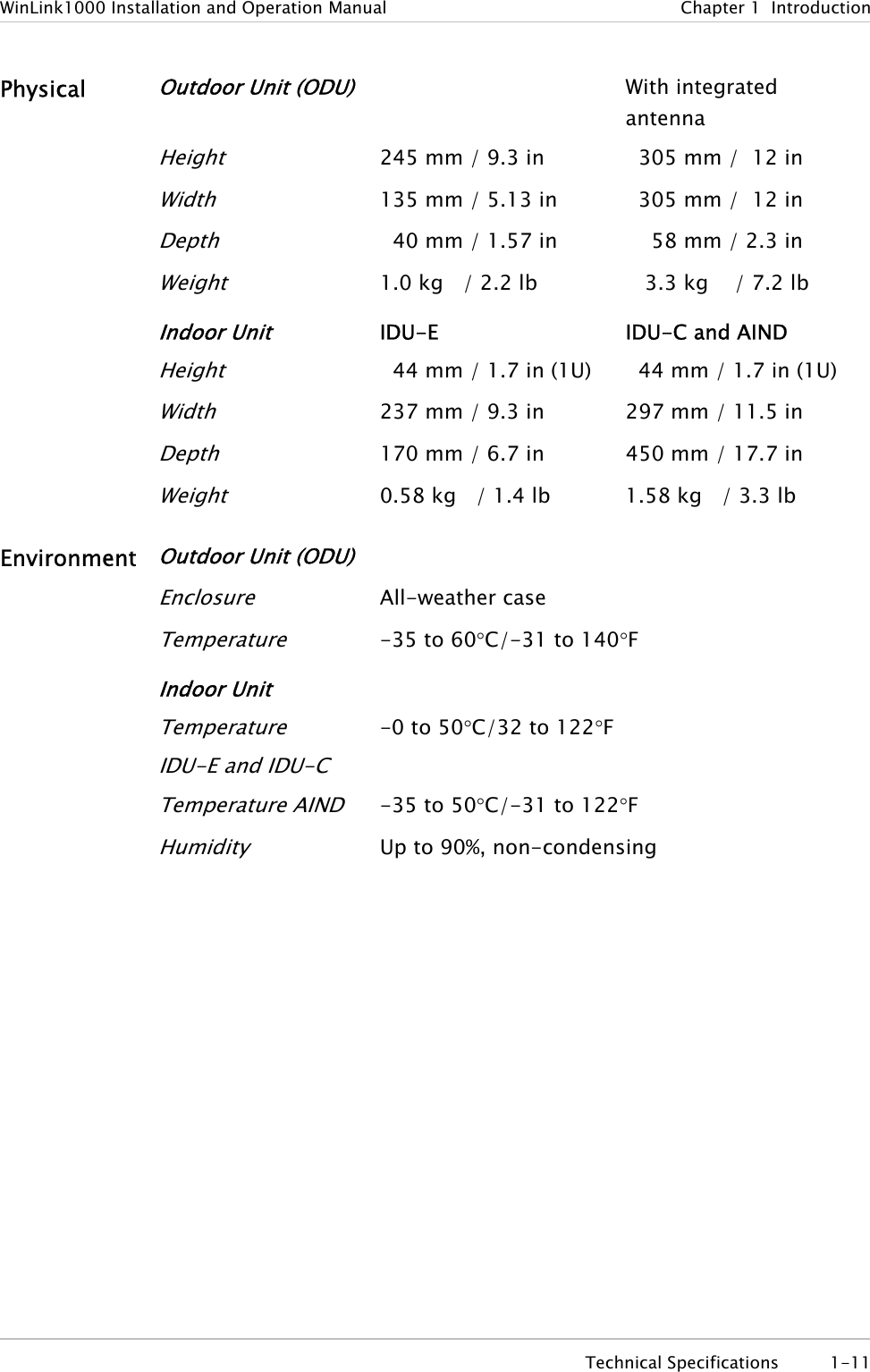
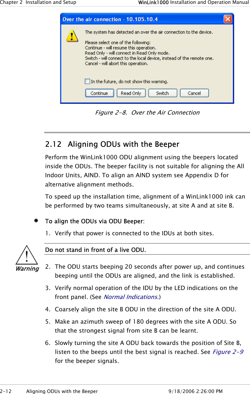
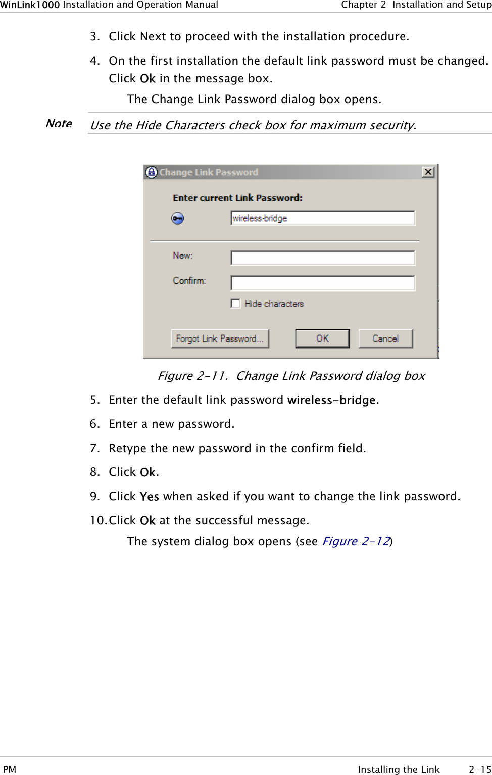
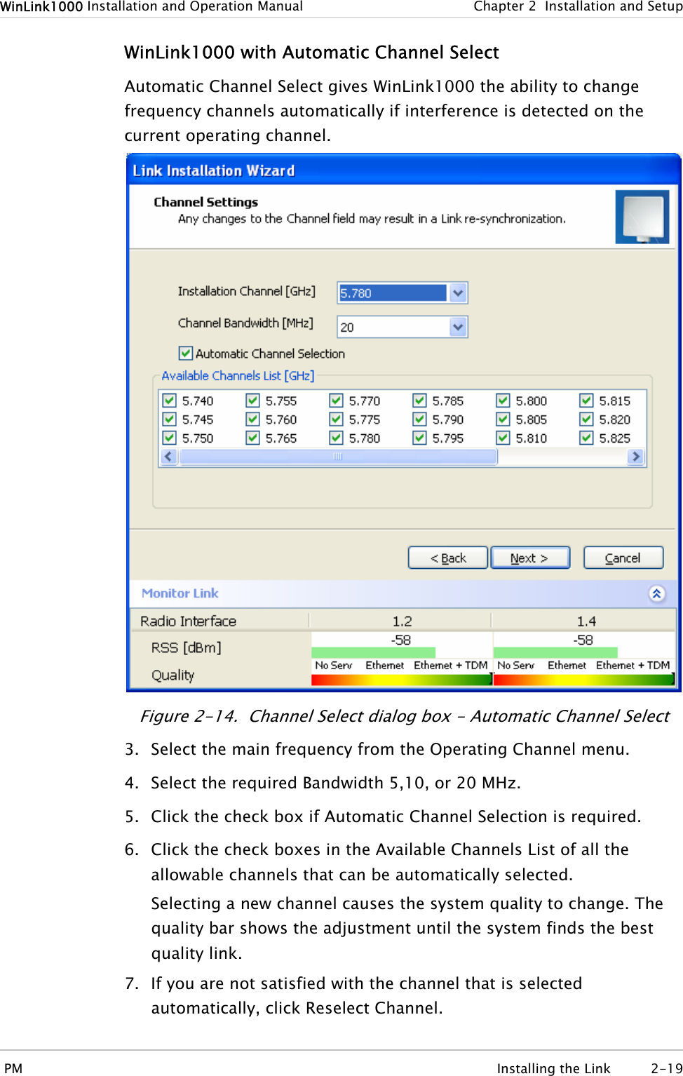
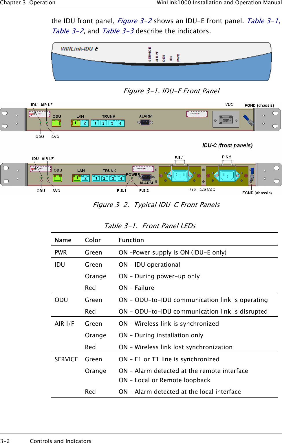
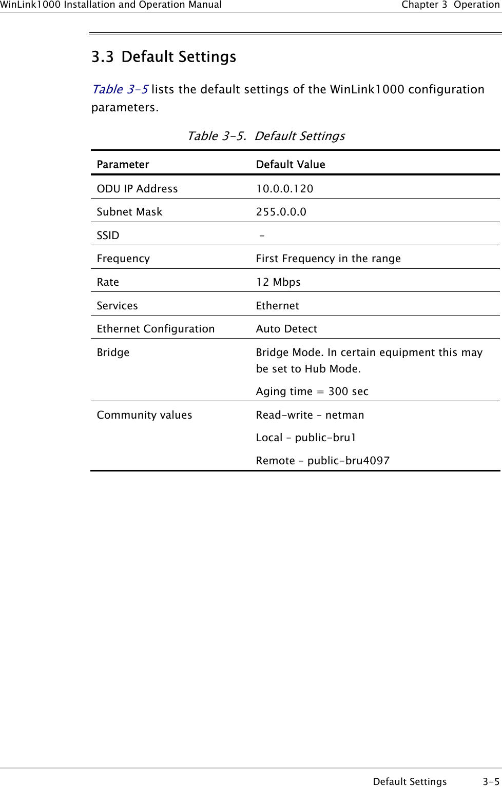
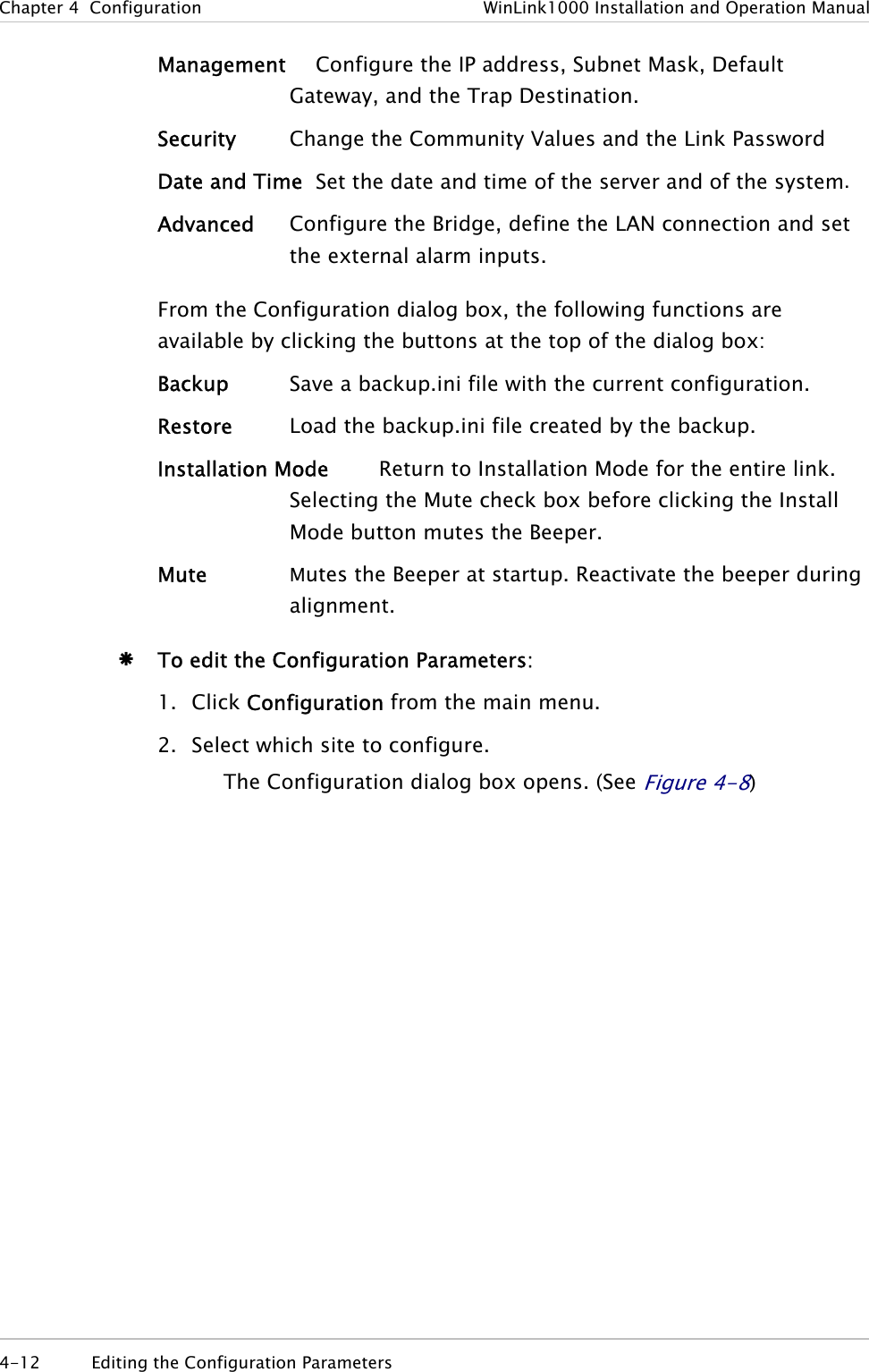
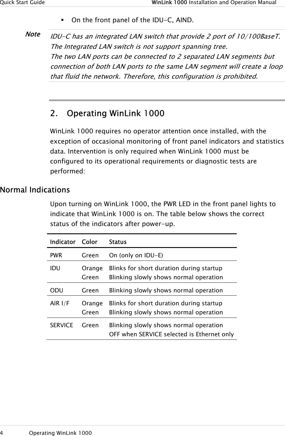
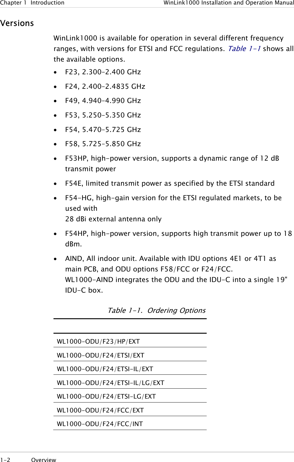
![WinLink1000 Installation and Operation Manual Chapter 2 Installation and Setup Beeper Sequence =beeper on =beeper off Description [approx. 1s] Best Signal so far Signal quality increased No change in signal Signal quality decreased [approx. 2s] No air link Figure 2-9. Beeper Sequence for ODU Alignment • Three beeps and a pause is the best signal NoteTwo beeps and a pause, signal quality increased One beep and pause is no signal change Any other signal detects no signal between ODUs. 7. Secure the site A ODU to the mast/wall. 8. At site B, adjust the ODU slowly whilst listening to the beeper sequence until the best signal is attained. 9. Secure the site B ODU to the mast/wall. 10. Monitor the link quality for about 15 minutes to verify stability. 2.13 Calculating the Air Interface Rate The Air Interface rate is the data transmission rate from one site to the other, over the wireless WinLink1000 interface. Use the Link Budget Calculator Utility in order to calculate the optimal air interface rate and the expected performance of the link operating at the user’s requirements. The ARA, Adaptive Rate Modulation feature performs this task automatically and ensures that the transmission rate is set to maximum whilst the link quality throughput is maintained. Æ To open the Link Budget Calculator Utility 1. Click Help on the Menu Bar. PM Calculating the Air Interface Rate 2-13](https://usermanual.wiki/Radwin/AMWL1580.User-Manual-1/User-Guide-719234-Page-36.png)