Radwin AMWL1580 Point to Point Broadband Radio System User Manual WinLink1000
Radwin Ltd. Point to Point Broadband Radio System WinLink1000
UserManual.wiki
>
Radwin
>
AMWL1580 User Manual
>
User Manual 2
Contents
1.
User Manual 1
2.
User Manual 2
User Manual 2
Navigation menu
Upload a User Manual
Namespaces
Wiki Guide
HTML
PDF
Info
Views
User Manual
Discussion / Help
Navigation

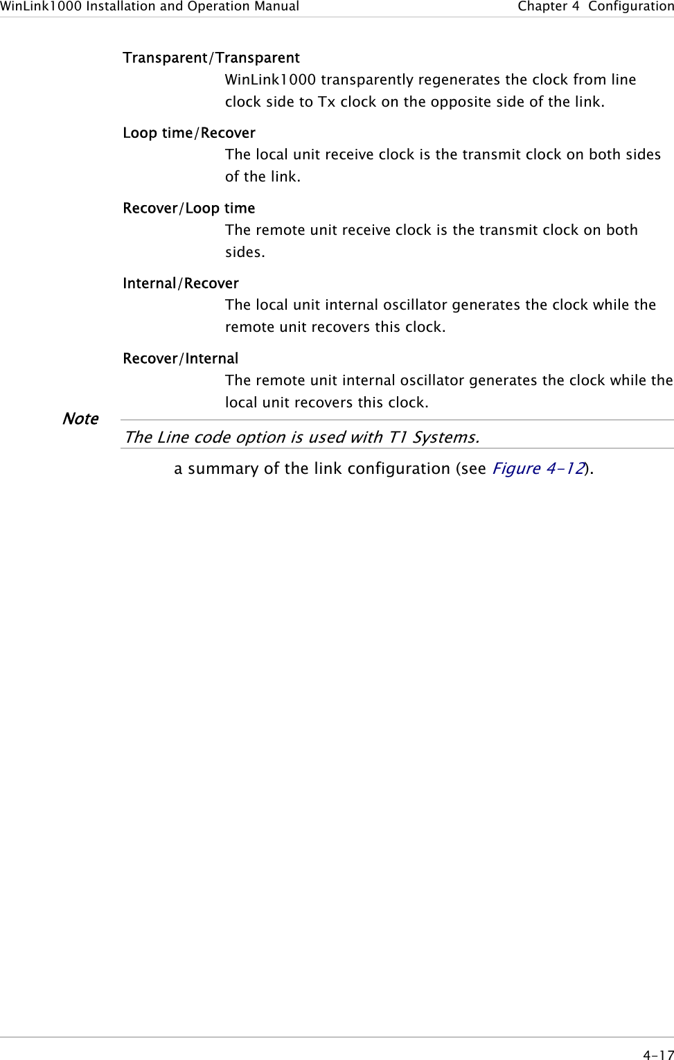
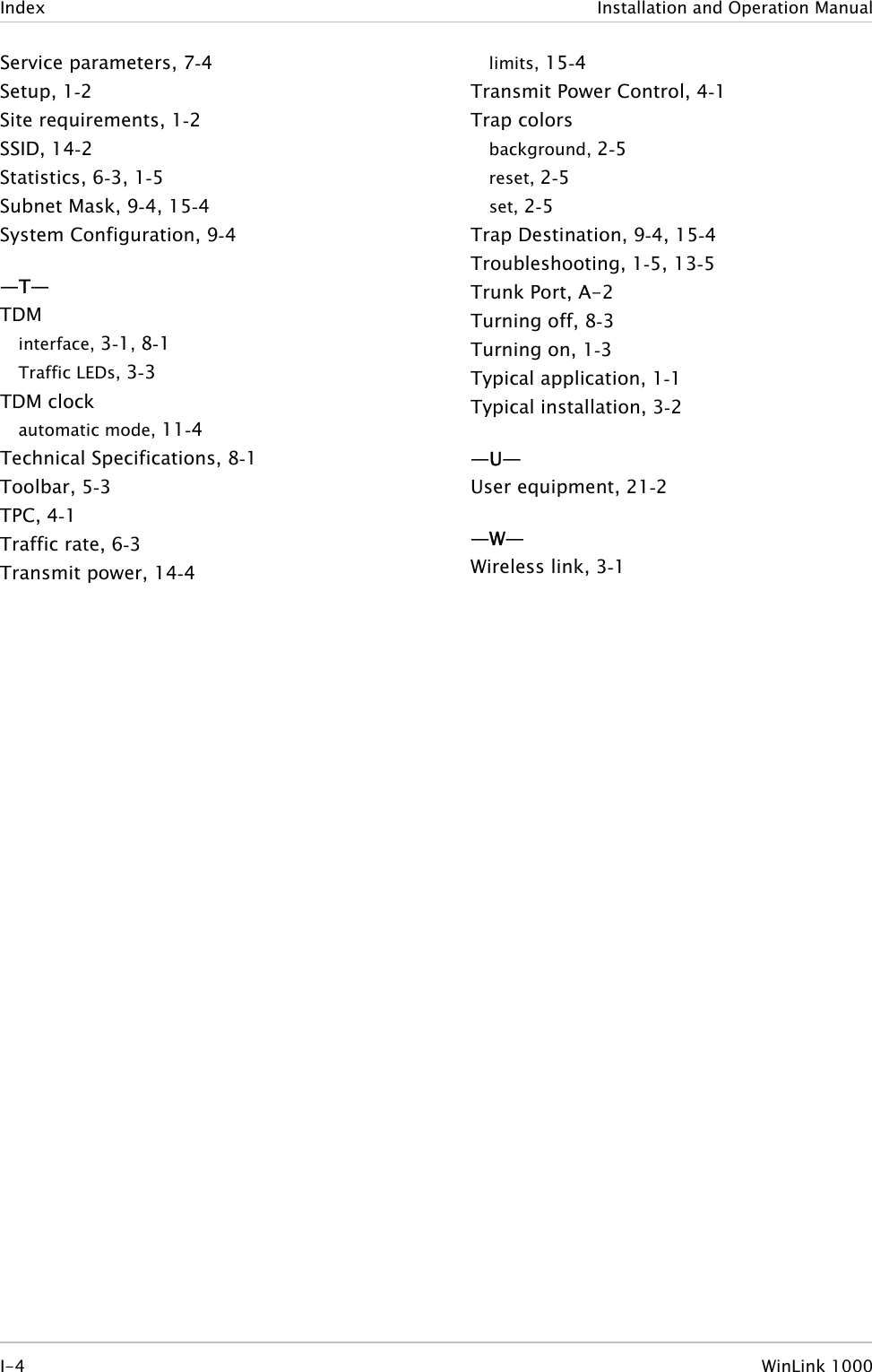
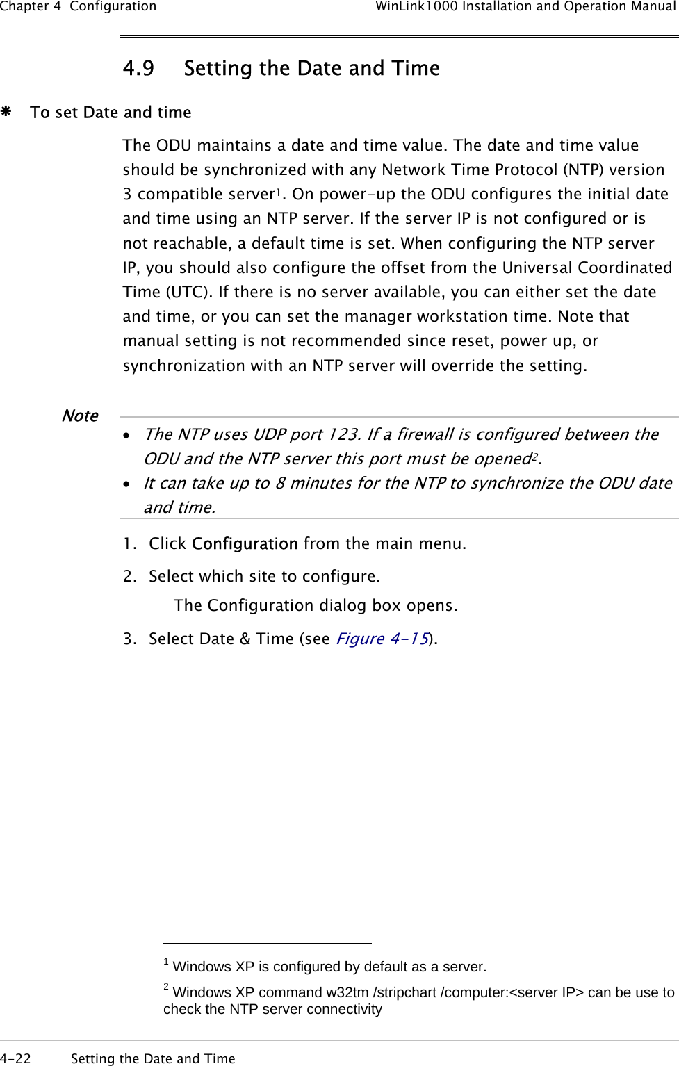
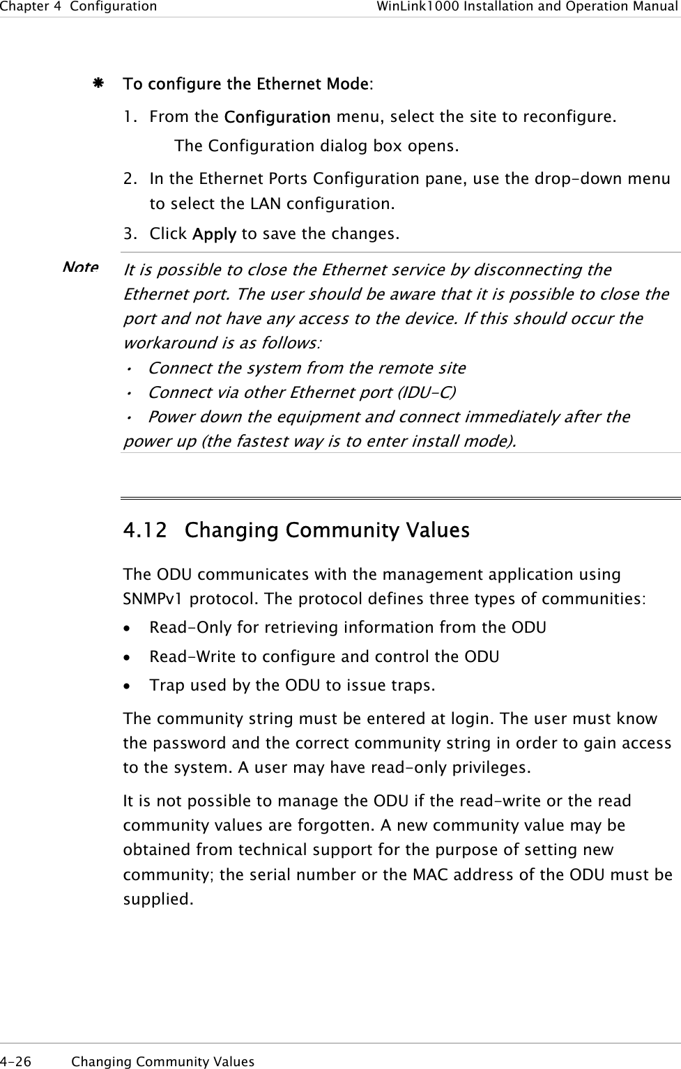
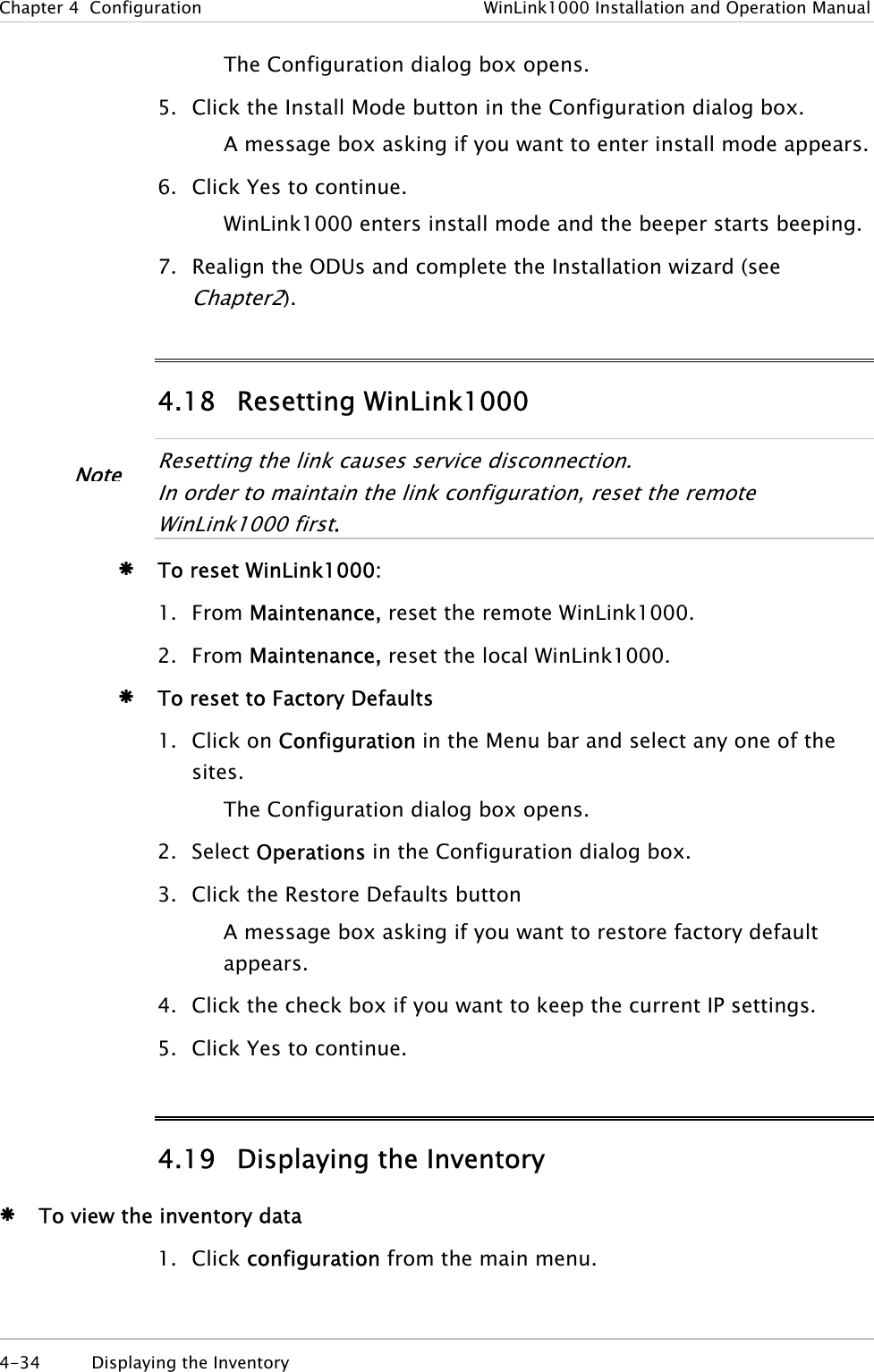
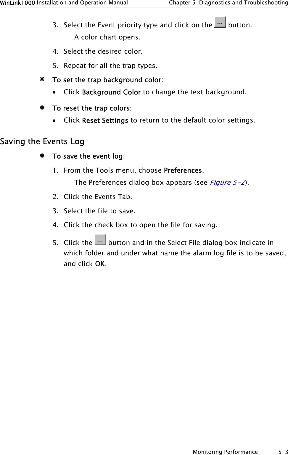
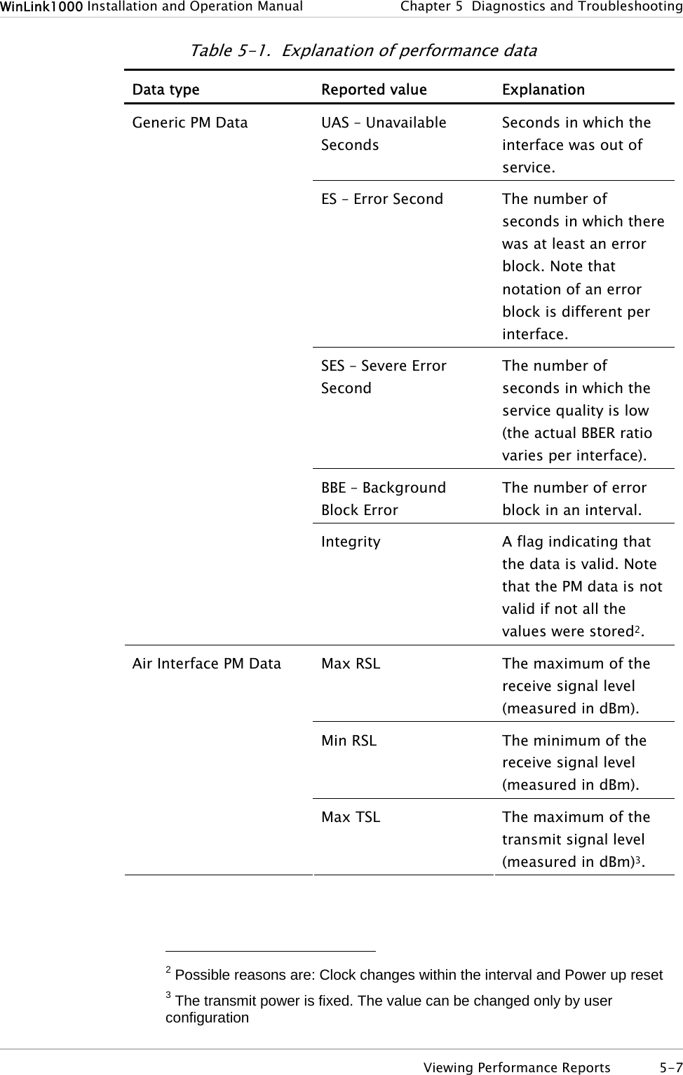
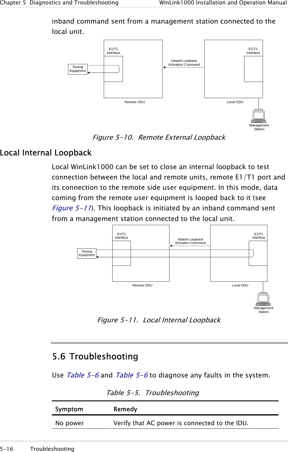
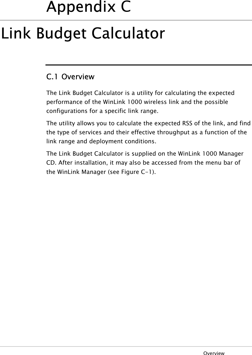
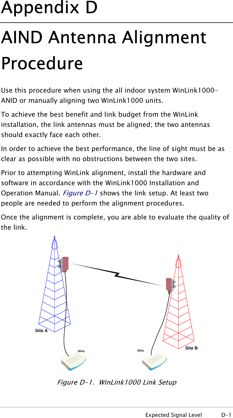
![Chapter 4 Configuration WinLink1000 Installation and Operation Manual Table 4-2. Typical Transmit Power Limits Regulation Version Min Tx [dB] Max Tx [dB] MaxTx at 36 Mbps [dB] MaxTx at 48 Mbps [dB] Power Control F58 4 16 14 10 Yes F58/EXT 4 16 14 10 Yes F49 14 15 15 14 No F53 -3 8 8 8 Yes F53/EXT 3 3 3 3 No F24 18 18 18 18 No FCC F53HP 10 16 14 10 Yes India F58CN -1 10 10 10 Yes China F24/EXT/ETSI -4 -4 -4 -4 No F54 2 8 8 8 Yes F54/ETSI 2 8 8 8 Yes ETSI F54-HG/EXT -3 3 3 3 Yes 4.8 Defining the Management Addresses Each site must be configured separately, first site A then site B. Æ To define the Management Addresses: 1. Click Configuration from the main menu. 2. Select which site to configure. The Configuration dialog box opens. 3. Select Management (see Figure 4-14). 4. Enter the IP address of the ODU in the IP address field. NoteIf performing configu ation from the WinLink manager, the IP address is entered in the login screen (rFigure 2-4) 4-20 Defining the Management Addresses](https://usermanual.wiki/Radwin/AMWL1580.User-Manual-2/User-Guide-719235-Page-8.png)
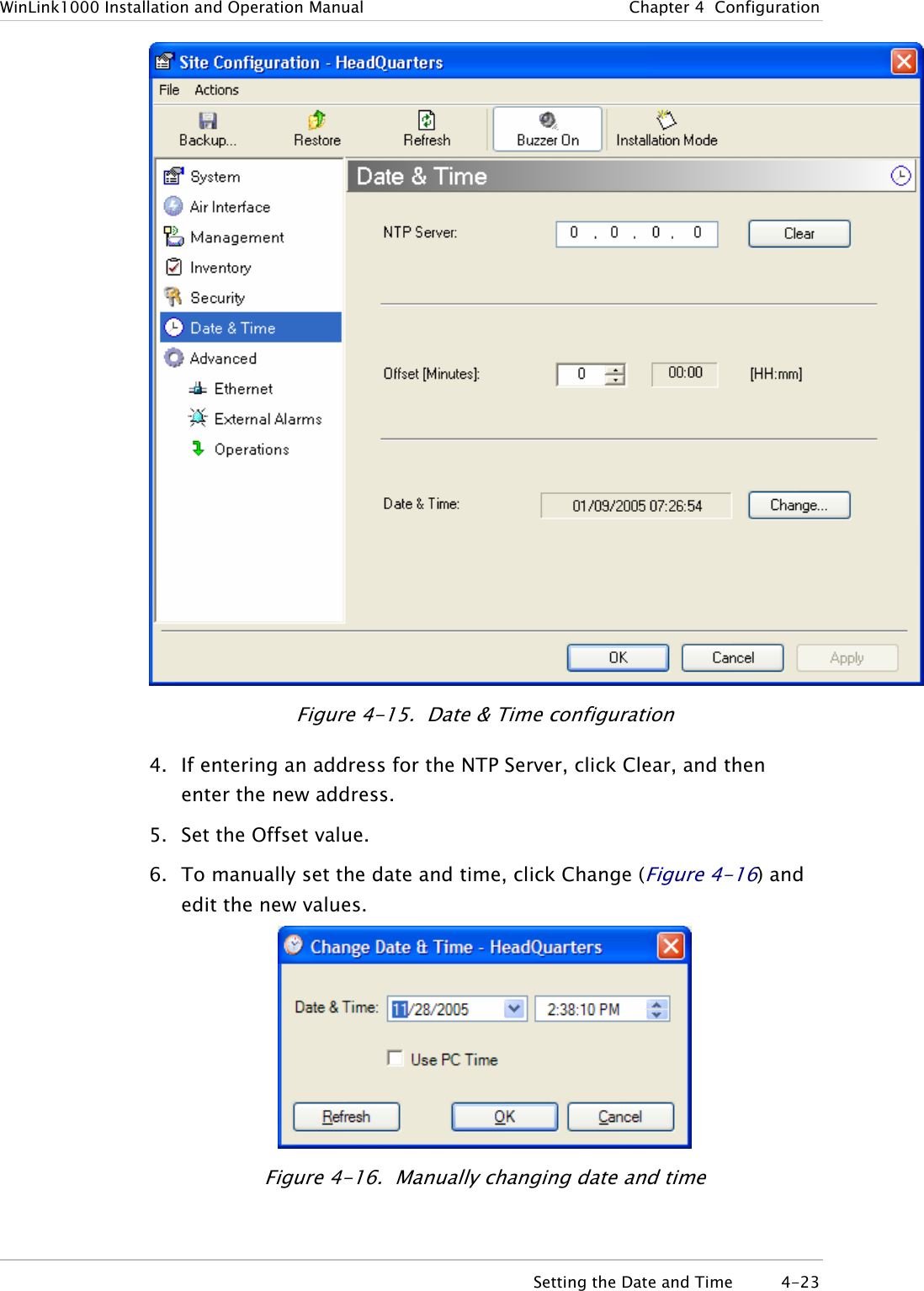
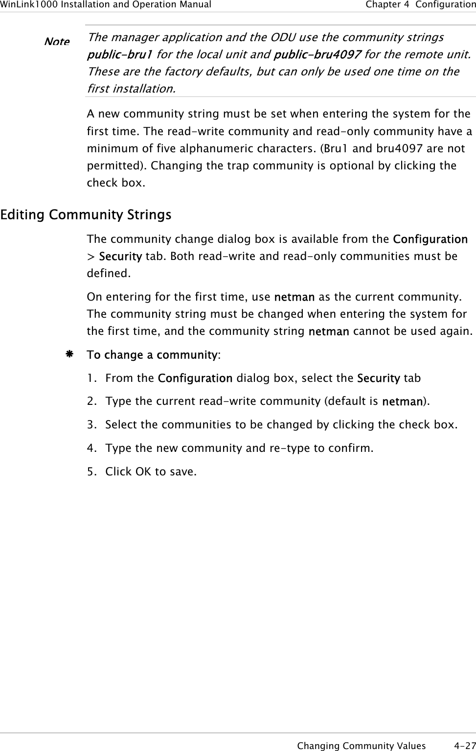
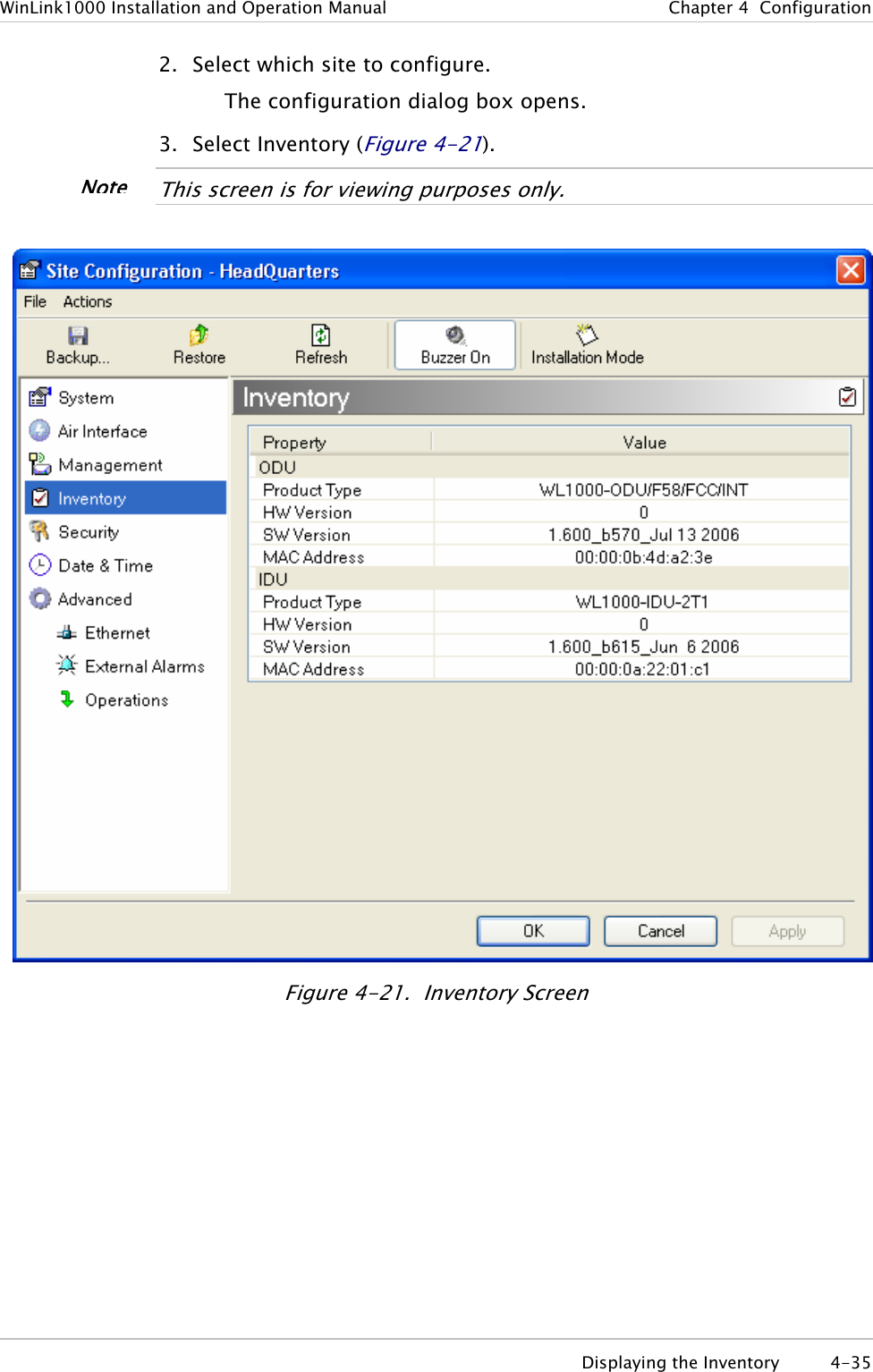
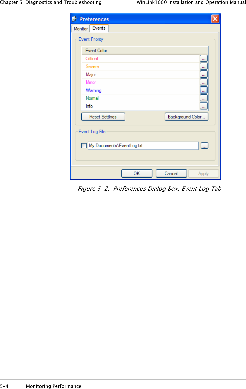
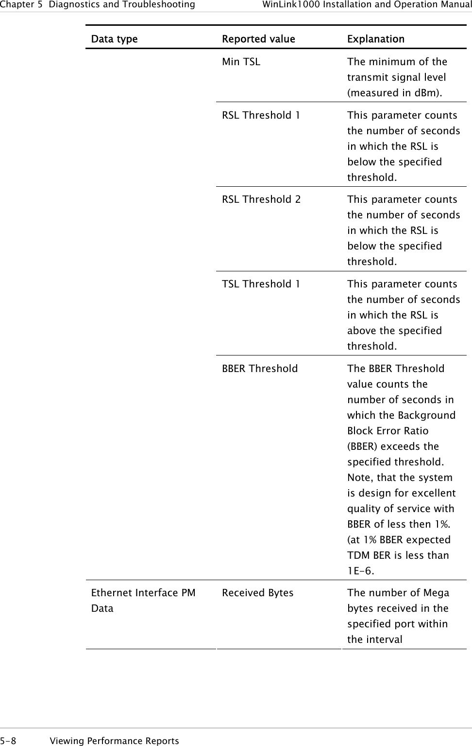

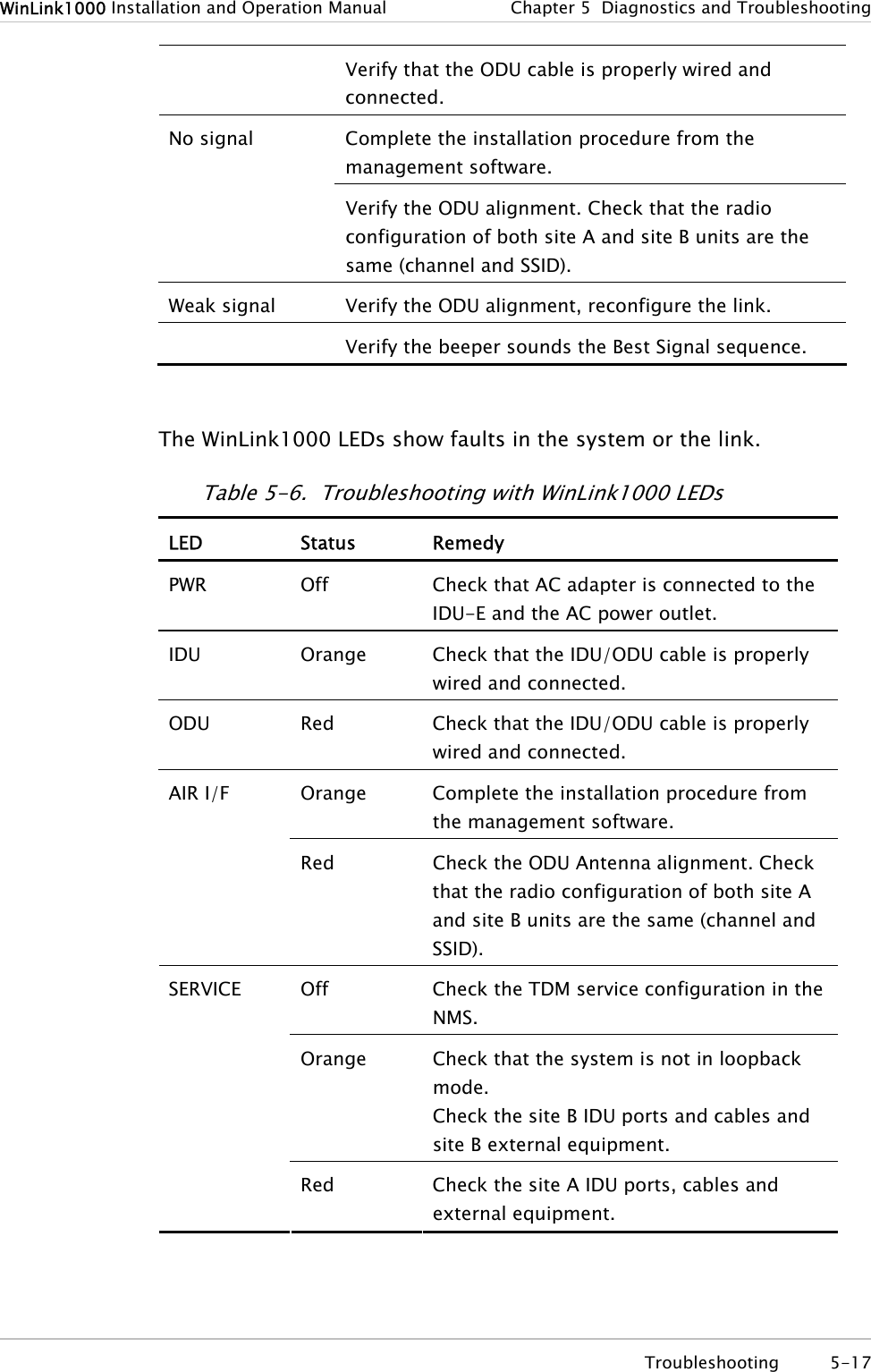
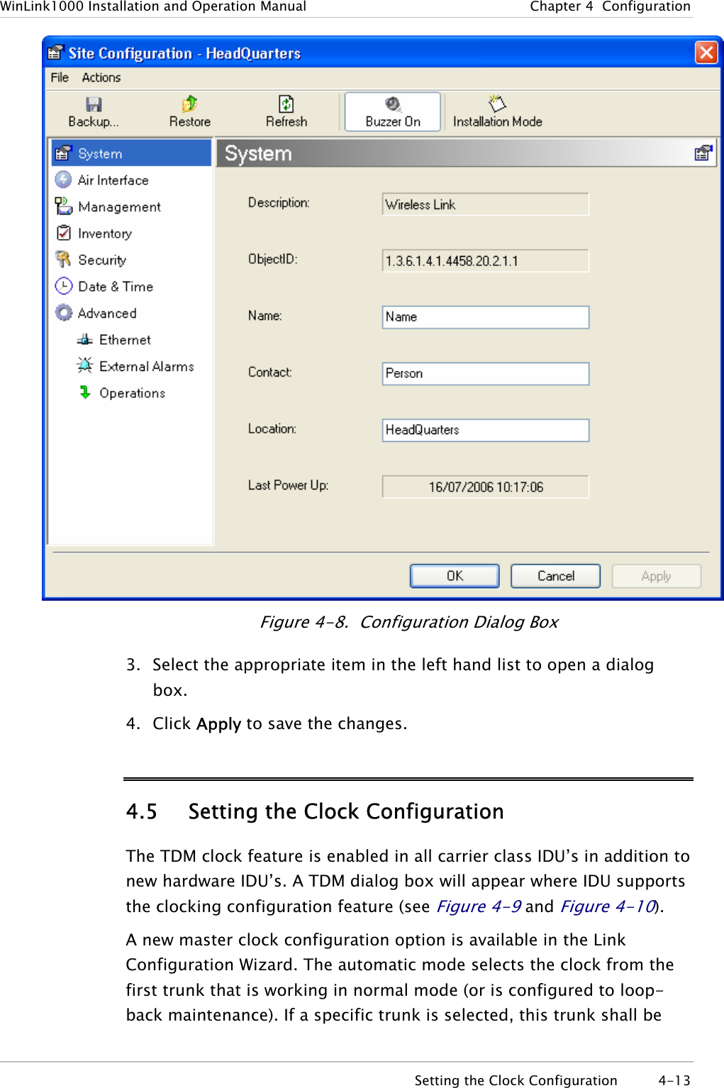
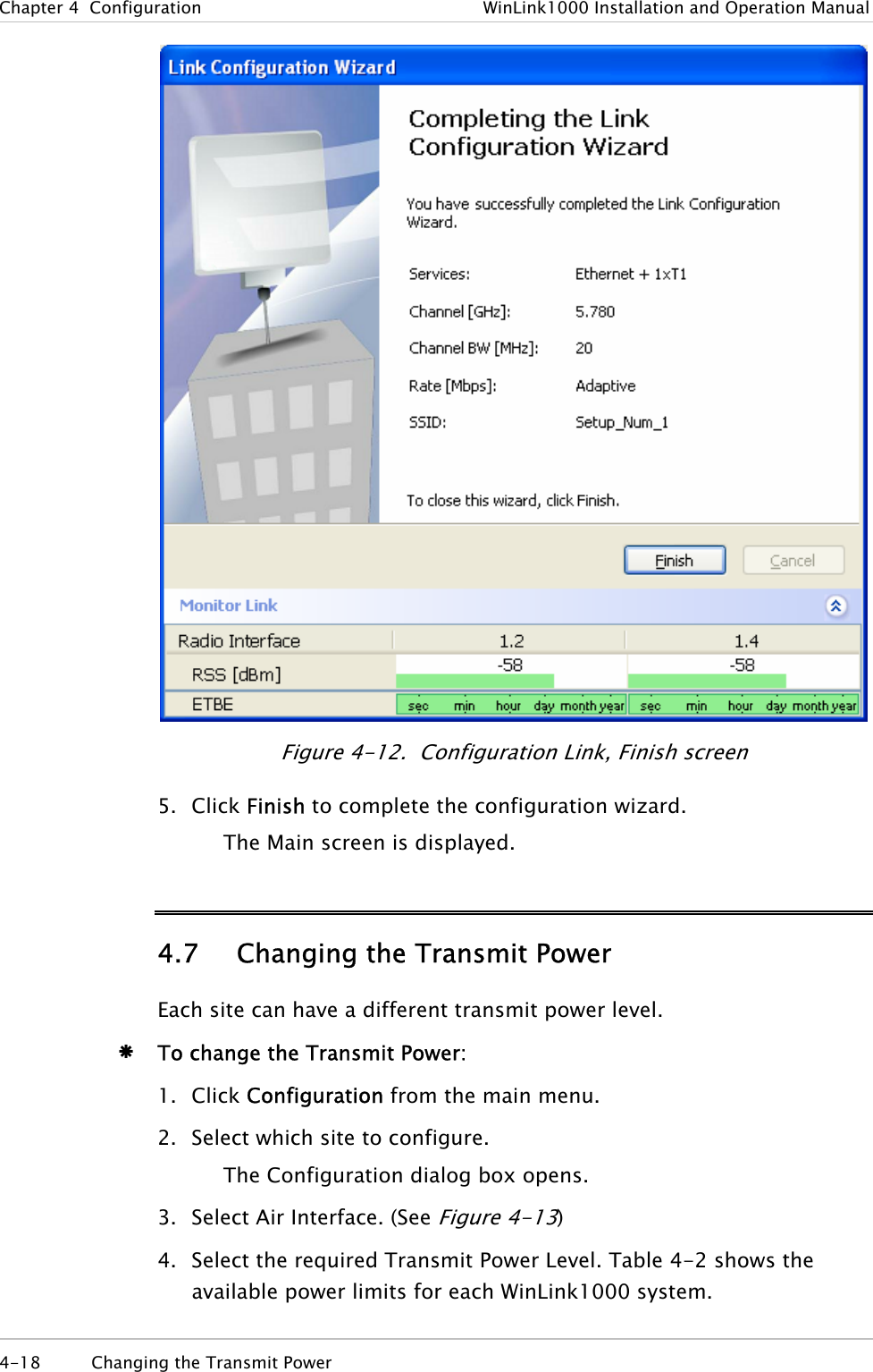
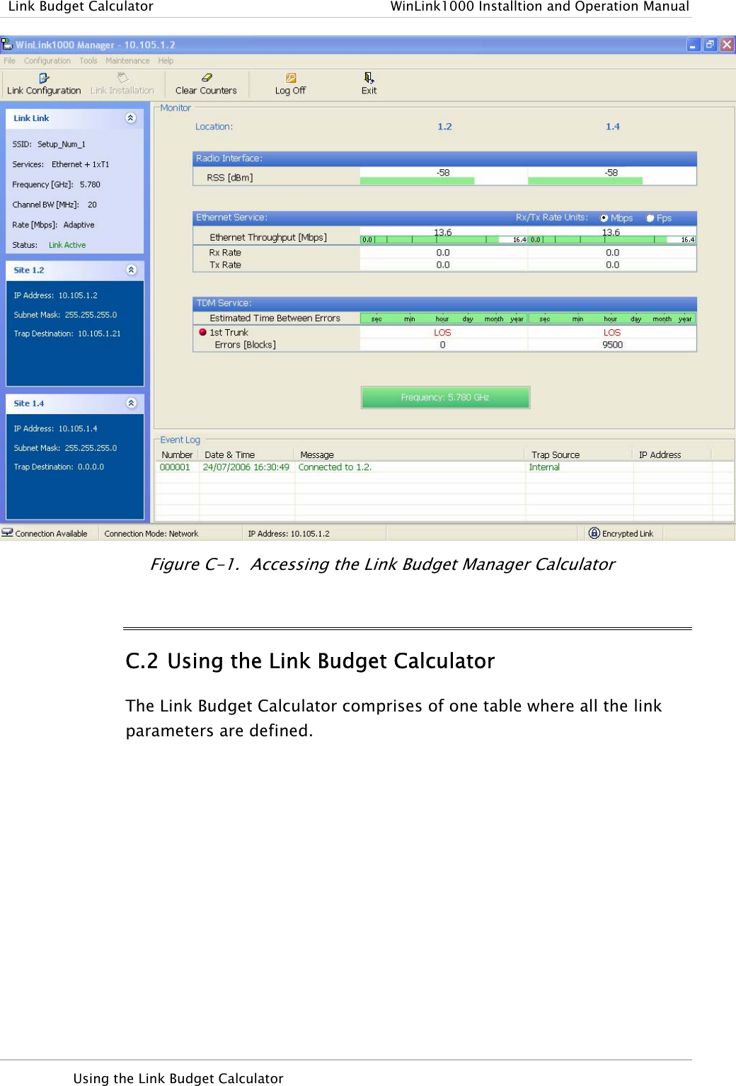
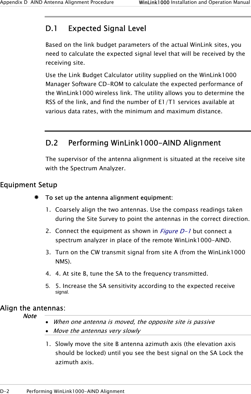
![WinLink1000 Installation and Operation Manual Chapter 5 Diagnostics and Troubleshooting A: Currently the system provides fixed channels, with one manual frequency setting. The manual setting provides flexibility of spectrum selection, including 5.735 MHz. Q: Can we mange WinLink1000 using SNMPc other than the supplied management software that comes with the units? A: Yes. The WinLink1000 is SNMP-based. WinLink1000 can be managed when using other SNMP software after implementing RADWIN MIB’s. Q: Can WinLink1000 be managed and configured via Telnet? A: No. Use only the WinLink1000 software manager. Q: Can I use WinLink1000 with any vendor’s external antenna? A: Yes. RADWIN supplies the WinLink1000 external ODU with an N-type typical connector. Any vendor’s external antenna that can be cascaded to our external unit can be used without problem. Please note that dB losses in the cascading cable between the external ODU and antenna should be taken into consideration. (In the supplied cascading cable of one meter we have 1 dB loss) Q: Do we need to add external arrestors on WinLink1000 cables? A: The WinLink1000 ODU includes arrestors and lightning protection. Therefore there is no need to add additional arrestors. Q: What is the actual Ethernet data rate and maximum throughput? A: The maximum net throughput of WinLink1000 is full duplex 18 Mbps. NoteWinLink1000 is a symmetrical system Q: What is the sensitivity for each rate of the WinLink1000? A: The rate sensitivities are: Rate [Mbps] Sensitivity [dB] 12 -84 18 -81 36 -74 Frequently Asked Questions 5-19](https://usermanual.wiki/Radwin/AMWL1580.User-Manual-2/User-Guide-719235-Page-42.png)
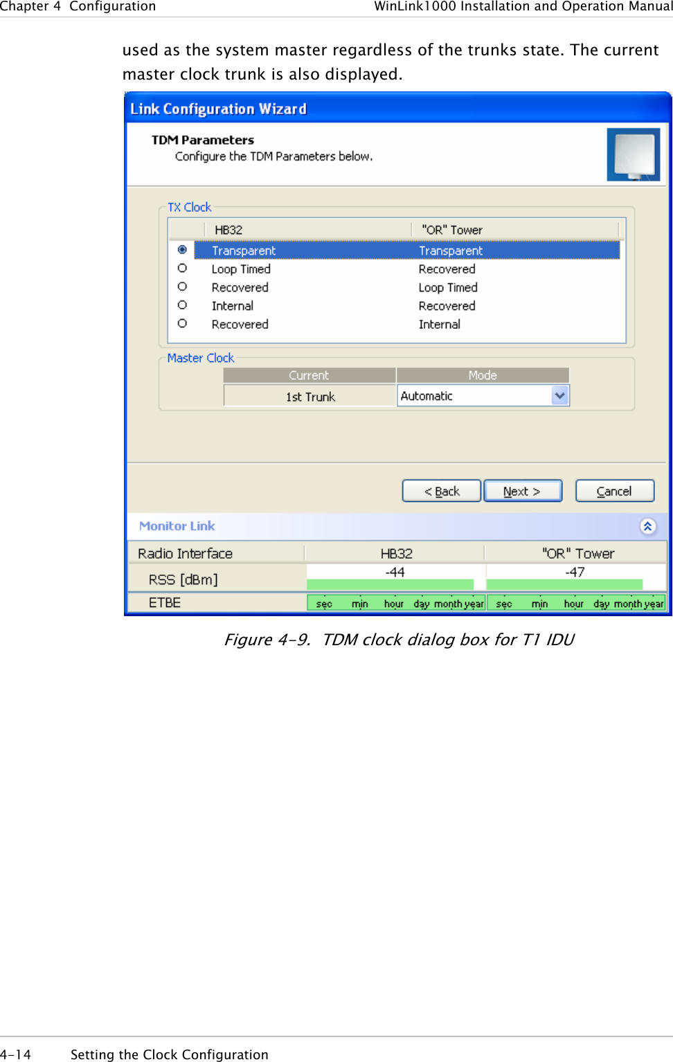
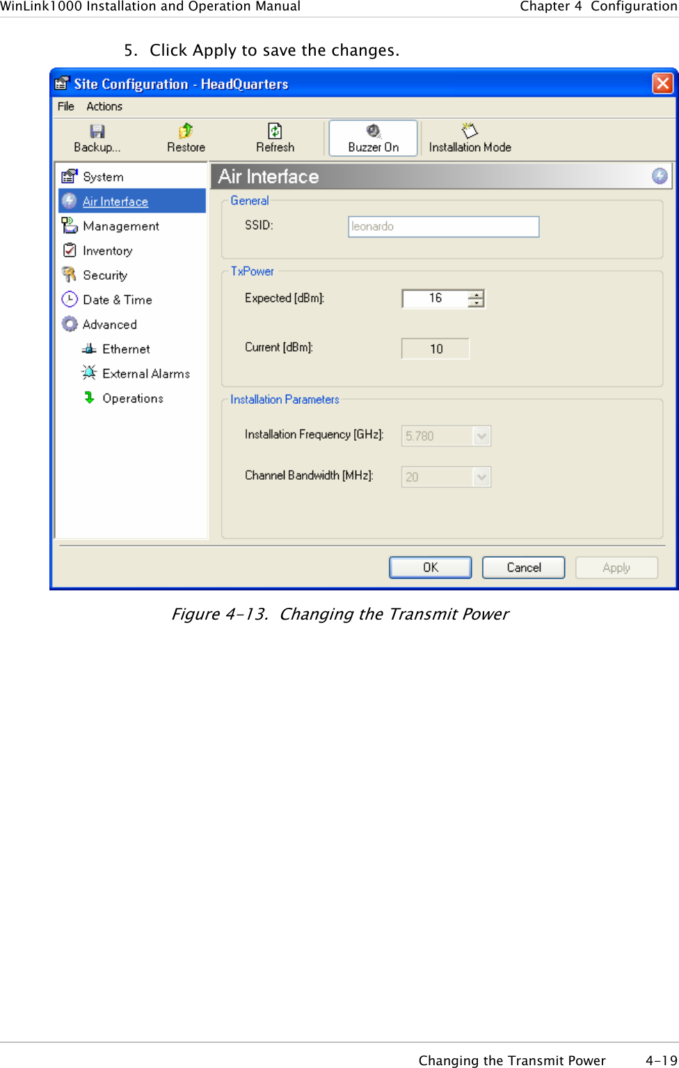
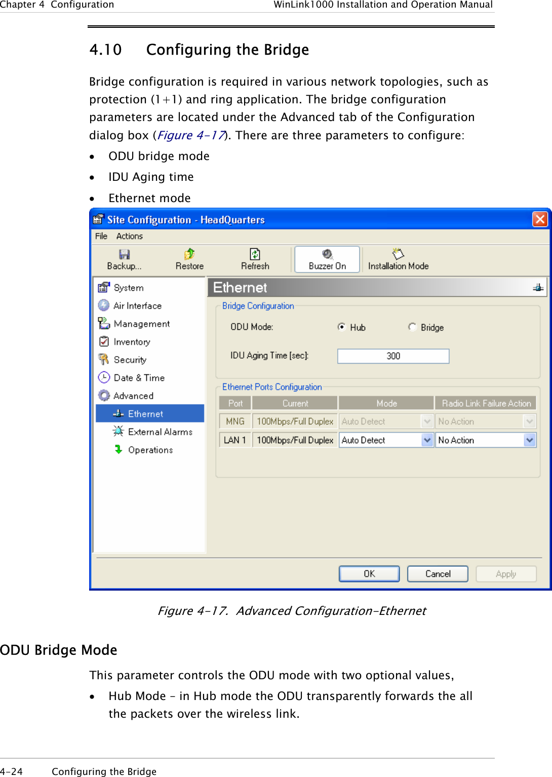
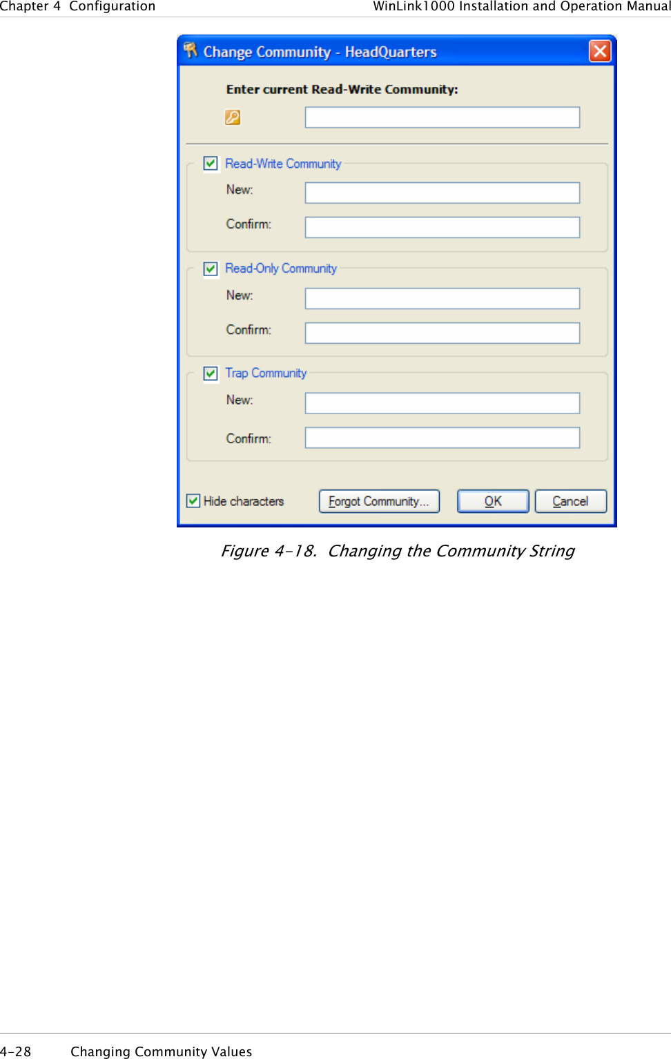
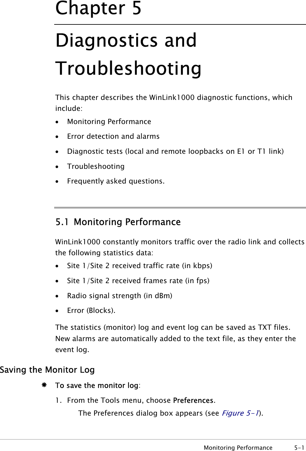
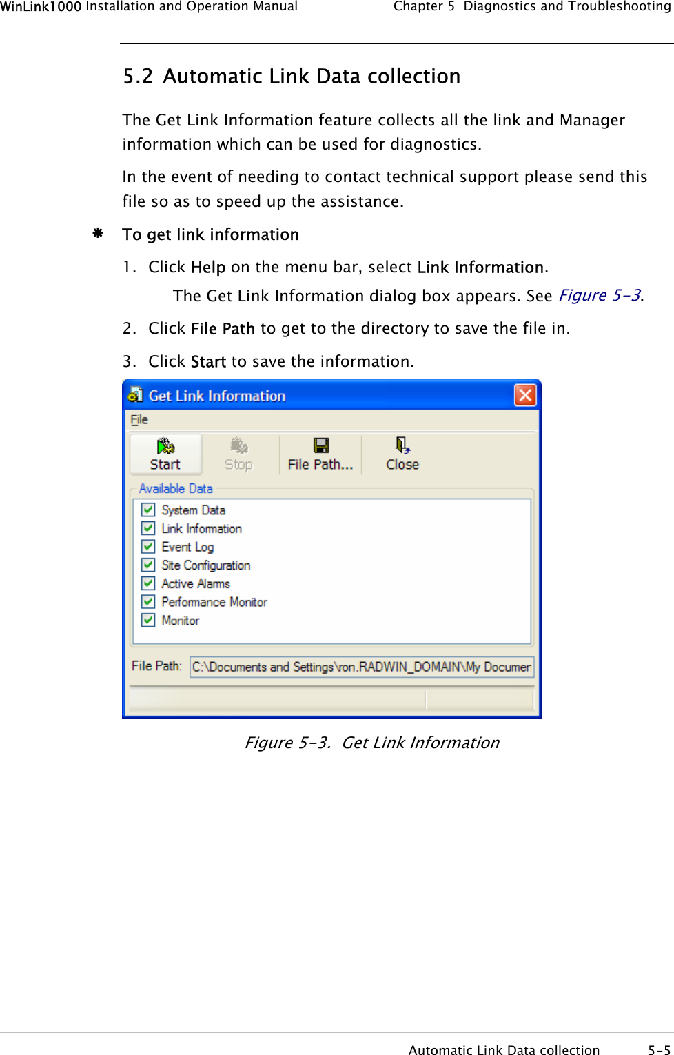
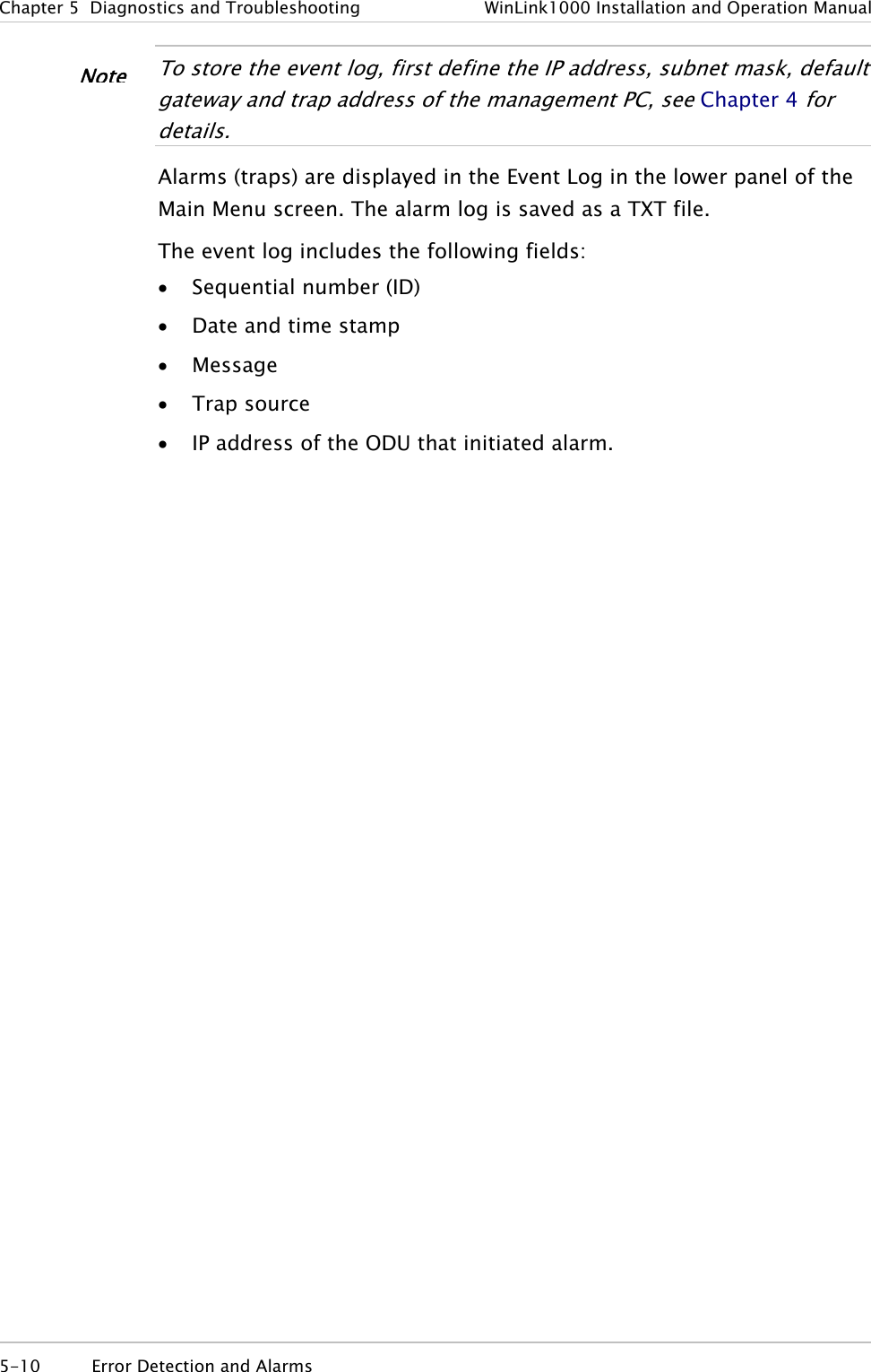
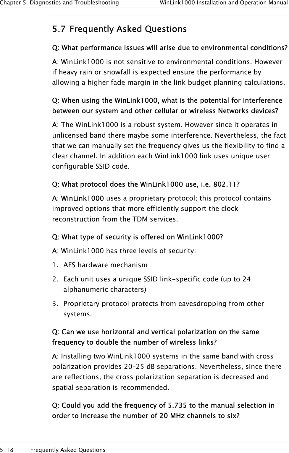
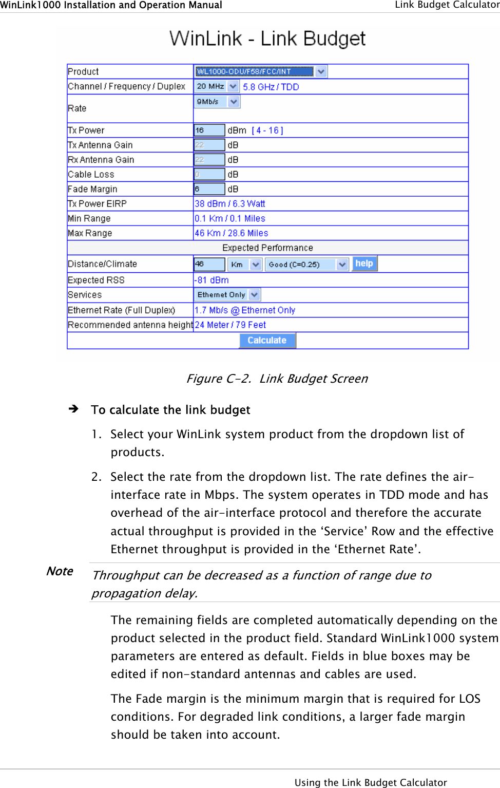
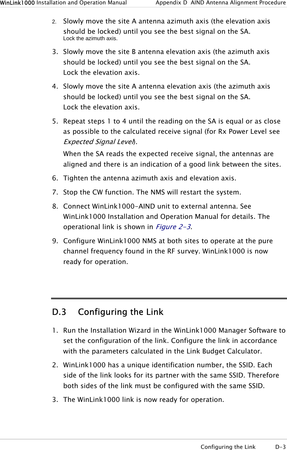
![Chapter 5 Diagnostics and Troubleshooting WinLink1000 Installation and Operation Manual Rate [Mbps] Sensitivity [dB] 48 -68 Q: Does WinLink1000 withhold any MAC Addresses? A: The WinLink1000 is a layer 2 Bridge (VLAN transparent). The built-in switch contains a MAC Address table up to 2047. Q: Can I use any category 5e cable in order to connect the IDU and ODU? A: The cable should be suitable for outdoor use, and shielded Category 5e. Q: What are the BER values expected in the WinLink1000 link? A: 10-11 (according to BER sensitivity threshold) Q: Does WinLink1000 use DSSS technique? A: No, WinLink1000 uses the advanced OFDM technique. Q: What are the main advantages of the WinLink1000 solution (e.g., wireline, wireless, etc.) over other possible alternatives? A: • Easy and intuitive installation using audio indication. • Easy configuration using the management software of overall link site-to-site, there is no need to travel between the two sites in order to change the configuration. • Easy migration between transition channels site-to-site. • Full backup option – backup and restore using ini files. • Very light ODU (1.5 kg). • No RF loses between IDU and ODU. • Robust Air Interface Layer 2 ARQ insures “error-free” Ethernet service even in harsh conditions. Retransmit mechanism for TDM esures low BER. • Integrated up to 4 E1/T1 and Ethernet radio over one single product. 5-20 Frequently Asked Questions](https://usermanual.wiki/Radwin/AMWL1580.User-Manual-2/User-Guide-719235-Page-43.png)
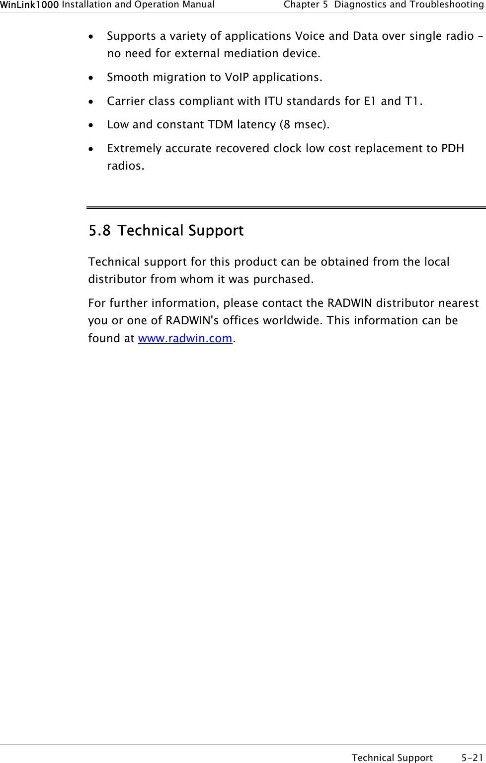
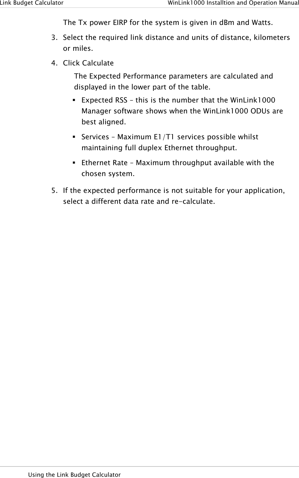
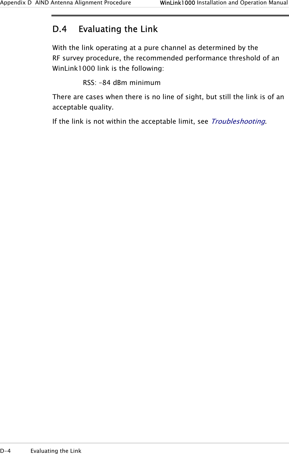
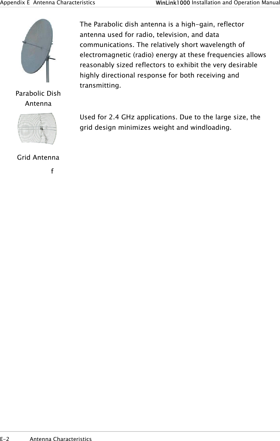
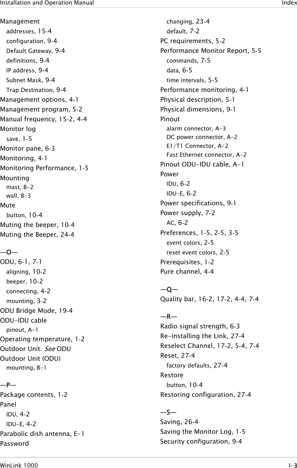
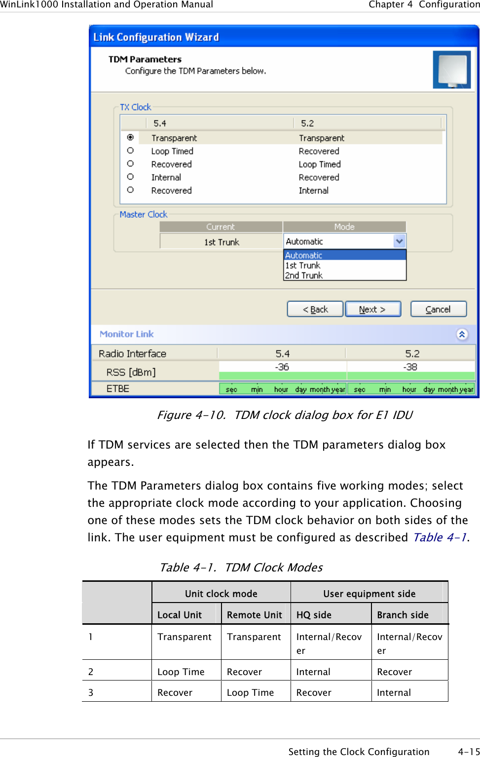
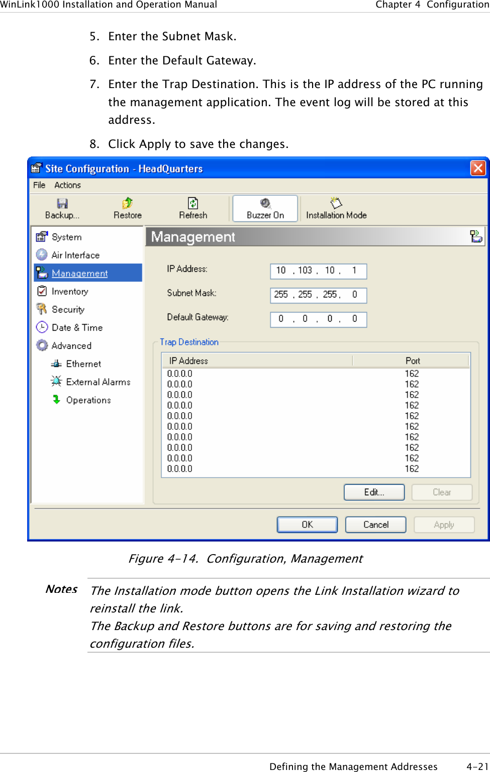
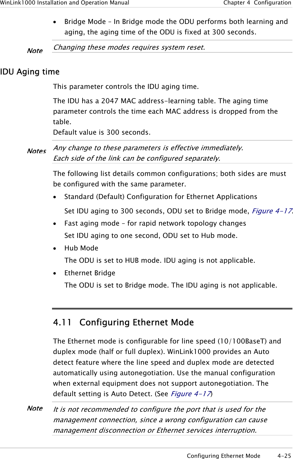
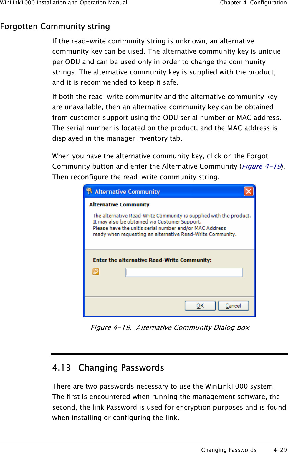
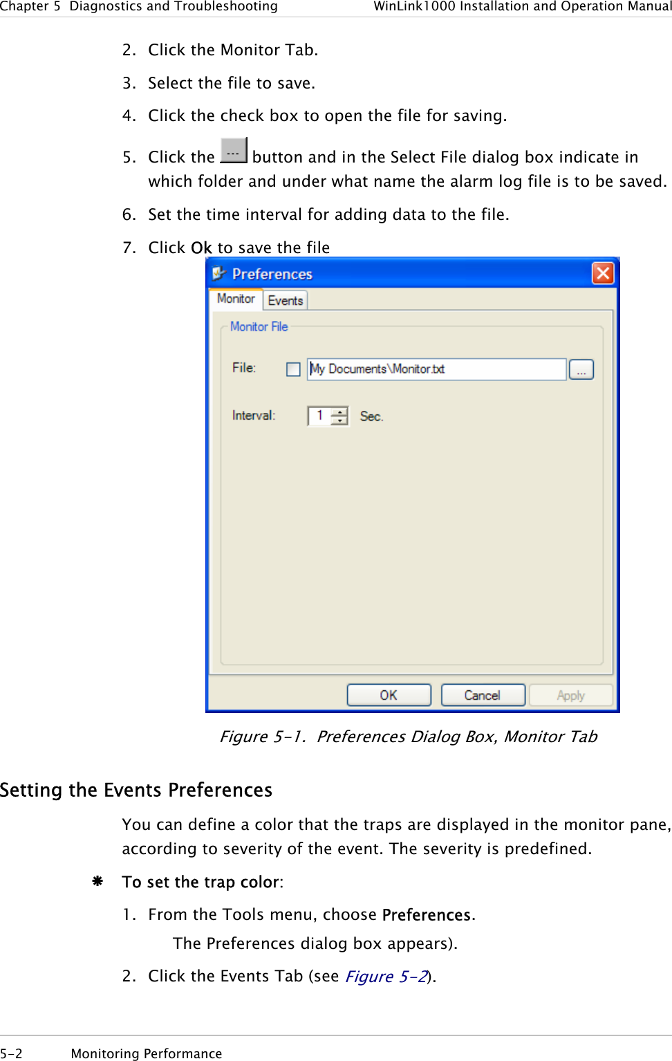
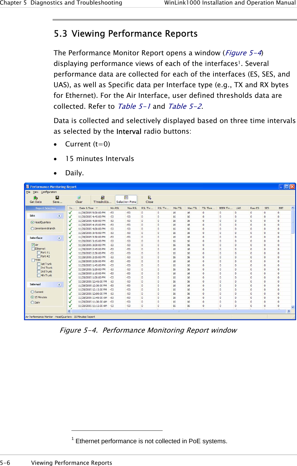
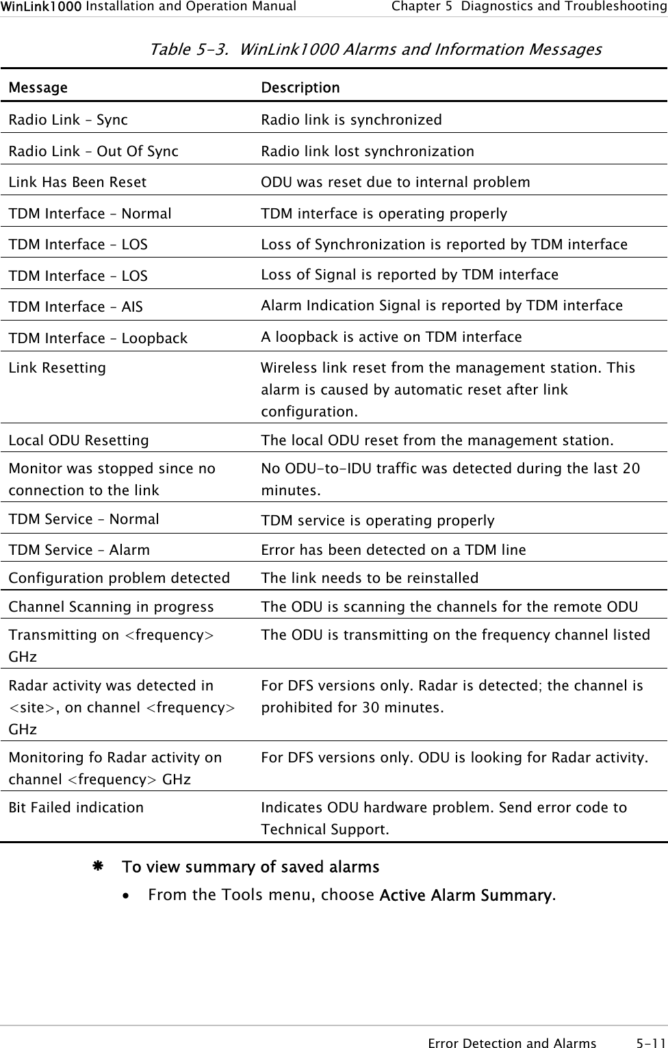
![Appendix E Antenna Characteristics An antenna is the radiating and receiving element from which the radio signal, in the form of RF power, is radiated to its surroundings and vice versa. The transmission range is a function of the antenna gain and transmitting power. These factors are limited by country regulations. WinLink1000 may be operated with an integrated antenna attached to the ODU unit, or with an external antenna wired to the ODU via an N-type connector. All cables and connections must be connected correctly to reduce losses. The required antenna impedance is 50Ω. Table E-1. Antenna Characteristics Type Gain[dBi] Max Range[km][miles]Beam [degrees] Dimensions [mm] [in] Weight [kg] [Ib] Connector Lightning Protection5.8, 5.4, 5.3 GHz Integrated Flat panel 22 40 25 9.0 305×305×58 12×12×2.3 0.5 1.1 NR Yes External Flat panel 28 80 50 4.5 600×600×51 23.6×23.6×25.0 11.0 N-type No 5.8 GHz only External Dish 32.5 80 50 4.5 Dia 900 Dia 35.4 10 22 N-type No 4.9 GHz External Flat panel 21 24 15 9.0 305×305×58 12×12×2.3 0.5 1.1 N-type Yes External Dish 27 80 50 5 Dia 600 Dia 23.6 5.0 11.0 N-type Yes 2.4 GHz Integrated Flat panel 17 40 25 20 305×305×58 12×12×2.3 0.5 1.1 NR Yes External Grid 24 80 50 7.5 600×997×380 23.5×39.2×15 2.0 4.6 N-type No Antenna Characteristics E-1](https://usermanual.wiki/Radwin/AMWL1580.User-Manual-2/User-Guide-719235-Page-62.png)