Radwin AMWL1580 Point to Point Broadband Radio System User Manual WinLink1000
Radwin Ltd. Point to Point Broadband Radio System WinLink1000
Radwin >
Contents
- 1. User Manual 1
- 2. User Manual 2
User Manual 2
WinLink1000 Installation and Operation Manual Chapter 4 Configuration
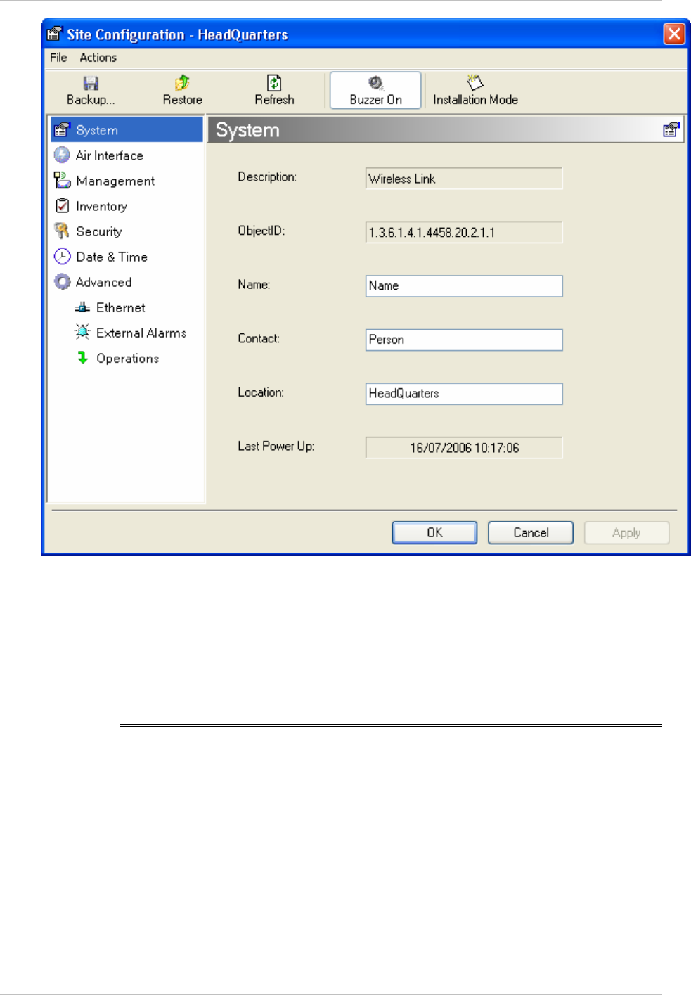
Figure
4-8. Configuration Dialog Box
3. Select the appropriate item in the left hand list to open a dialog
box.
4. Click Apply to save the changes.
4.5 Setting the Clock Configuration
The TDM clock feature is enabled in all carrier class IDU’s in addition to
new hardware IDU’s. A TDM dialog box will appear where IDU supports
the clocking configuration feature (see
Figure
4-9
and
Figure
4-10
).
A new master clock configuration option is available in the Link
Configuration Wizard. The automatic mode selects the clock from the
first trunk that is working in normal mode (or is configured to loop-
back maintenance). If a specific trunk is selected, this trunk shall be
Setting the Clock Configuration 4-13
Chapter 4 Configuration WinLink1000 Installation and Operation Manual
used as the system master regardless of the trunks state. The current
master clock trunk is also displayed.
Figure
4-9. TDM clock dialog box for T1 IDU
4-14 Setting the Clock Configuration
WinLink1000 Installation and Operation Manual Chapter 4 Configuration
Figure
4-10. TDM clock dialog box for E1 IDU
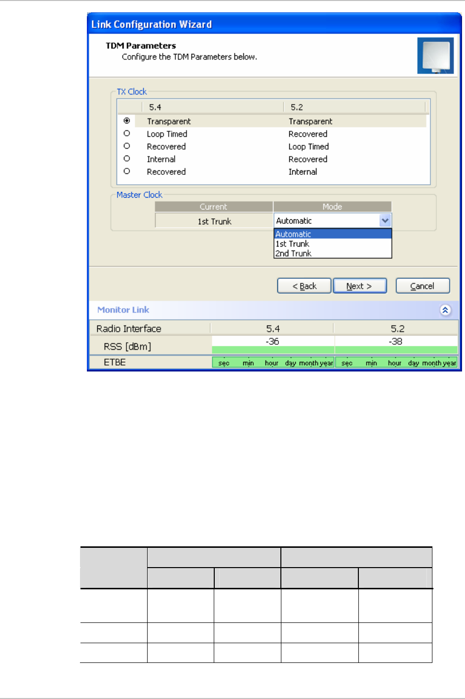
If TDM services are selected then the TDM parameters dialog box
appears.
The TDM Parameters dialog box contains five working modes; select
the appropriate clock mode according to your application. Choosing
one of these modes sets the TDM clock behavior on both sides of the
link. The user equipment must be configured as described
Table
4-1
.
Table
4-1. TDM Clock Modes
Unit clock mode User equipment side
Local Unit Remote Unit HQ side Branch side
1 Transparent Transparent Internal/Recov
er
Internal/Recov
er
2 Loop Time Recover Internal Recover
3 Recover Loop Time Recover Internal
Setting the Clock Configuration 4-15

Chapter 4 Configuration WinLink1000 Installation and Operation Manual
Unit clock mode User equipment side
Local Unit Remote Unit HQ side Branch side
4 Internal Recover Recover Recover
5 Recover Internal Recover Recover
4-16 Setting the Clock Configuration

WinLink1000 Installation and Operation Manual Chapter 4 Configuration
Transparent/Transparent
WinLink1000 transparently regenerates the clock from line
clock side to Tx clock on the opposite side of the link.
Loop time/Recover
The local unit receive clock is the transmit clock on both sides
of the link.
Recover/Loop time
The remote unit receive clock is the transmit clock on both
sides.
Internal/Recover
The local unit internal oscillator generates the clock while the
remote unit recovers this clock.
Recover/Internal
The remote unit internal oscillator generates the clock while the
local unit recovers this clock.
Not
e
The Line code option is used with T1 Systems.
a summary of the link configuration (see
Figure
4-12
).
4-17
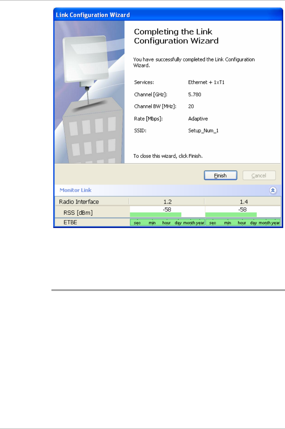
Chapter 4 Configuration WinLink1000 Installation and Operation Manual
Figure
4-12. Configuration Link, Finish screen
5. Click Finish to complete the configuration wizard.
The Main screen is displayed.
4.7 Changing the Transmit Power
Each site can have a different transmit power level.
Æ To change the Transmit Power:
1. Click Configuration from the main menu.
2. Select which site to configure.
The Configuration dialog box opens.
3. Select Air Interface. (See
Figure
4-13
)
4. Select the required Transmit Power Level. Table 4-2 shows the
available power limits for each WinLink1000 system.
4-18 Changing the Transmit Power
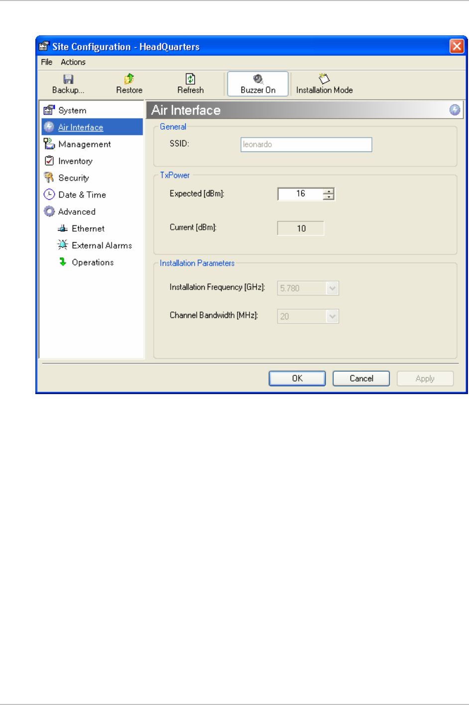
WinLink1000 Installation and Operation Manual Chapter 4 Configuration
5. Click Apply to save the changes.
Figure
4-13. Changing the Transmit Power
Changing the Transmit Power 4-19

Chapter 4 Configuration WinLink1000 Installation and Operation Manual
Table
4-2. Typical Transmit Power Limits
Regulation Version Min Tx
[dB]
Max Tx
[dB]
MaxTx at
36 Mbps
[dB]
MaxTx
at
48 Mbps
[dB]
Power
Control
F58 4 16 14 10 Yes
F58/EXT 4 16 14 10 Yes
F49 14 15 15 14 No
F53 -3 8 8 8 Yes
F53/EXT 3 3 3 3 No
F24 18 18 18 18 No
FCC
F53HP 10 16 14 10 Yes
India F58CN -1 10 10 10 Yes
China F24/EXT/ET
SI
-4 -4 -4 -4 No
F54 2 8 8 8 Yes
F54/ETSI 2 8 8 8 Yes
ETSI
F54-
HG/EXT
-3 3 3 3 Yes
4.8 Defining the Management Addresses
Each site must be configured separately, first site A then site B.
Æ To define the Management Addresses:
1. Click Configuration from the main menu.
2. Select which site to configure.
The Configuration dialog box opens.
3. Select Management (see
Figure
4-14
).
4. Enter the IP address of the ODU in the IP address field.
Note
If performing configu ation from the WinLink manager, the IP address
is entered in the login screen (
r
Figure 2-4)
4-20 Defining the Management Addresses
WinLink1000 Installation and Operation Manual Chapter 4 Configuration
5. Enter the Subnet Mask.
6. Enter the Default Gateway.
7. Enter the Trap Destination. This is the IP address of the PC running
the management application. The event log will be stored at this
address.
8. Click Apply to save the changes.
Figure
4-14. Configuration, Management
Notes
The Installation mode button opens the Link Installation wizard to
reinstall the link.
The Backup and Restore buttons are for saving and restoring the
configuration files.
Defining the Management Addresses 4-21

Chapter 4 Configuration WinLink1000 Installation and Operation Manual
4.9 Setting the Date and Time
Æ To set Date and time
The ODU maintains a date and time value. The date and time value
should be synchronized with any Network Time Protocol (NTP) version
3 compatible server1. On power-up the ODU configures the initial date
and time using an NTP server. If the server IP is not configured or is
not reachable, a default time is set. When configuring the NTP server
IP, you should also configure the offset from the Universal Coordinated
Time (UTC). If there is no server available, you can either set the date
and time, or you can set the manager workstation time. Note that
manual setting is not recommended since reset, power up, or
synchronization with an NTP server will override the setting.
•
The NTP uses UDP port 123. If a firewall is configured between the
ODU and the NTP ser er this port must be openedv
2
.
•
It can take up to 8 minutes for the NTP to synchronize the ODU date
and time.
1. Click Configuration from the main menu.
2. Select which site to configure.
The Configuration dialog box opens.
3. Select Date & Time (see
Figure
4-15
).
Not
e
1 Windows XP is configured by default as a server.
2 Windows XP command w32tm /stripchart /computer:<server IP> can be use to
check the NTP server connectivity
4-22 Setting the Date and Time
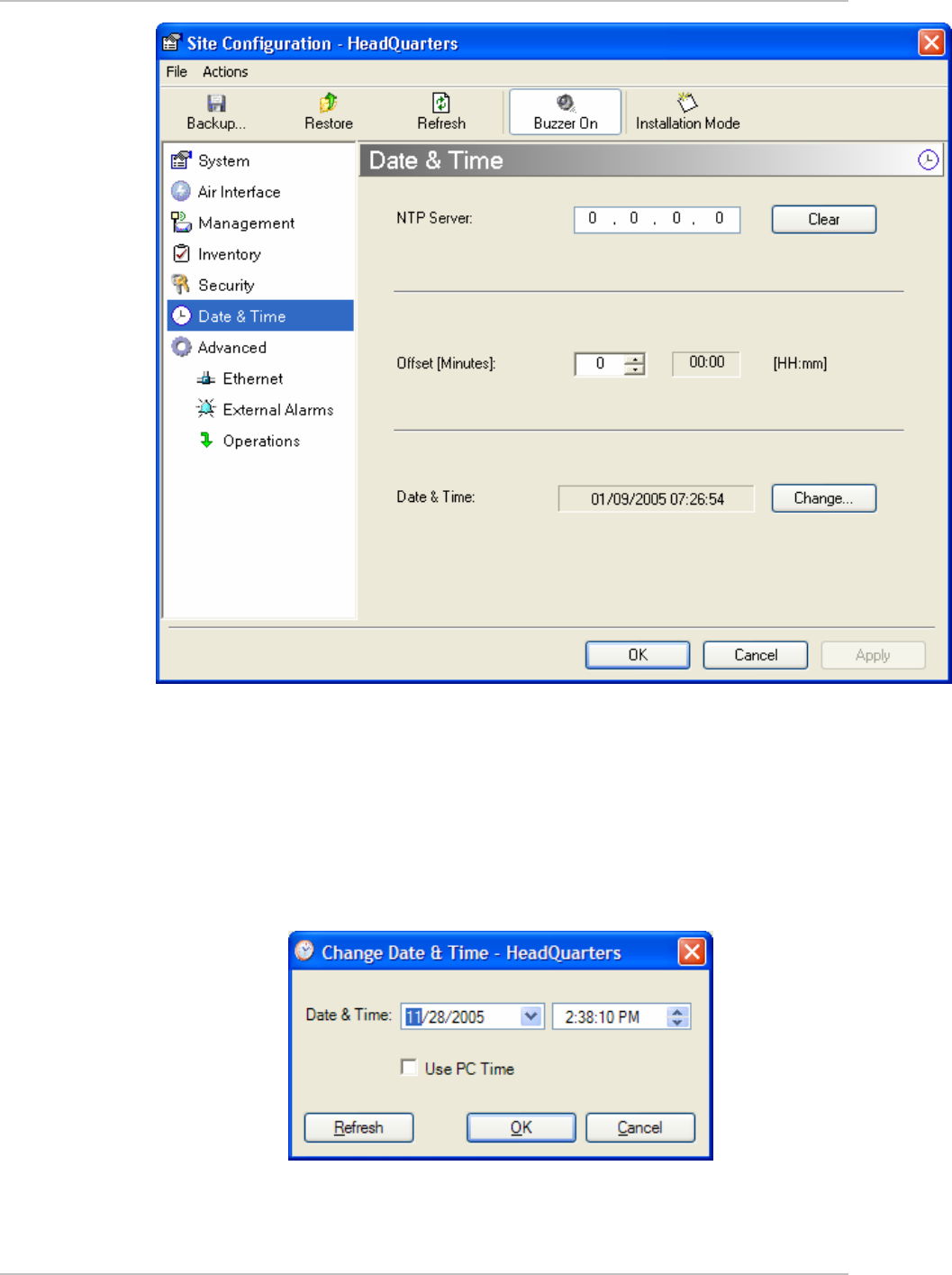
WinLink1000 Installation and Operation Manual Chapter 4 Configuration
Figure
4-15. Date & Time configuration
4. If entering an address for the NTP Server, click Clear, and then
enter the new address.
5. Set the Offset value.
6. To manually set the date and time, click Change (
Figure
4-16
) and
edit the new values.
Figure
4-16. Manually changing date and time
Setting the Date and Time 4-23
Chapter 4 Configuration WinLink1000 Installation and Operation Manual
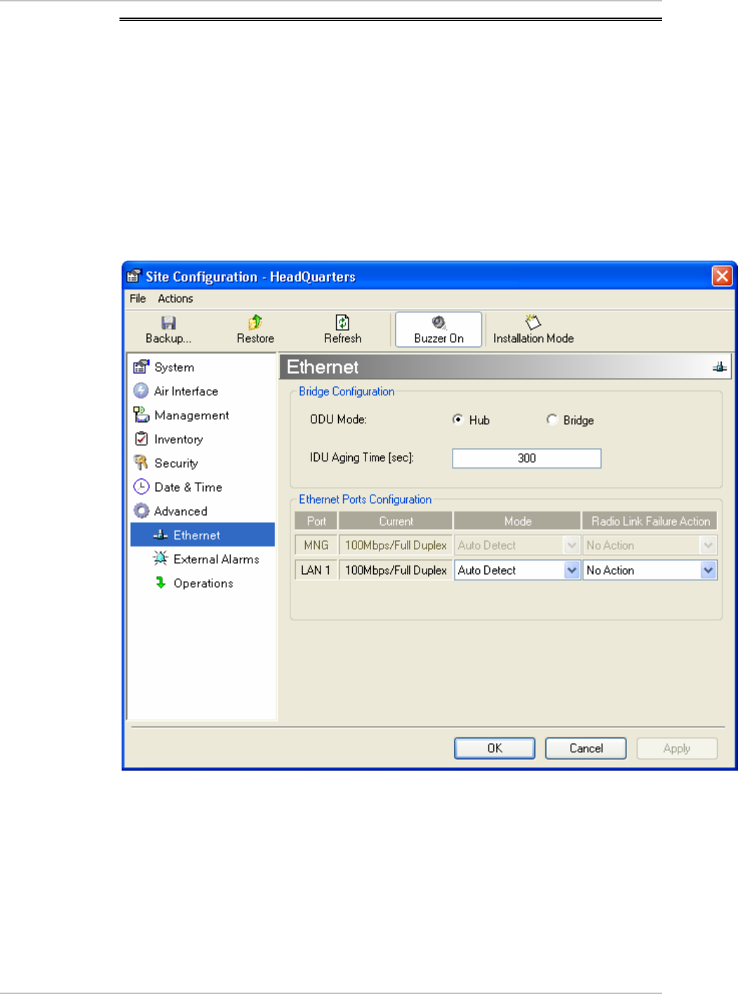
4.10 Configuring the Bridge
Bridge configuration is required in various network topologies, such as
protection (1+1) and ring application. The bridge configuration
parameters are located under the Advanced tab of the Configuration
dialog box (
Figure
4-17
). There are three parameters to configure:
• ODU bridge mode
• IDU Aging time
• Ethernet mode
Figure
4-17. Advanced Configu ation-Ethernet r
ODU Bridge Mode
This parameter controls the ODU mode with two optional values,
• Hub Mode – in Hub mode the ODU transparently forwards the all
the packets over the wireless link.
4-24 Configuring the Bridge

WinLink1000 Installation and Operation Manual Chapter 4 Configuration
• Bridge Mode – In Bridge mode the ODU performs both learning and
aging, the aging time of the ODU is fixed at 300 seconds.
Changing these modes requires system reset.
Note
IDU Aging time
This parameter controls the IDU aging time.
The IDU has a 2047 MAC address-learning table. The aging time
parameter controls the time each MAC address is dropped from the
table.
Default value is 300 seconds.
Any change to these parameters is effective immediately.
Each side of the link can be configured separately.
The following list details common configurations; both sides are must
be configured with the same parameter.
Notes
• Standard (Default) Configuration for Ethernet Applications
Set IDU aging to 300 seconds, ODU set to Bridge mode,
Figure
4-17
.
• Fast aging mode – for rapid network topology changes
Set IDU aging to one second, ODU set to Hub mode.
• Hub Mode
The ODU is set to HUB mode. IDU aging is not applicable.
• Ethernet Bridge
The ODU is set to Bridge mode. The IDU aging is not applicable.
4.11 Configuring Ethernet Mode
The Ethernet mode is configurable for line speed (10/100BaseT) and
duplex mode (half or full duplex). WinLink1000 provides an Auto
detect feature where the line speed and duplex mode are detected
automatically using autonegotiation. Use the manual configuration
when external equipment does not support autonegotiation. The
default setting is Auto Detect. (See
Figure
4-17
)
It is not recommended to configure the port that i used for the
management connection, since a wrong configuration can cause
management disconnection or Ethernet services interruption.
s
Note
Configuring Ethernet Mode 4-25

Chapter 4 Configuration WinLink1000 Installation and Operation Manual
Æ To configure the Ethernet Mode:
1. From the Configuration menu, select the site to reconfigure.
The Configuration dialog box opens.
2. In the Ethernet Ports Configuration pane, use the drop-down menu
to select the LAN configuration.
3. Click Apply to save the changes.
Note
It is possible to close the Ethernet service by disconnecting the
Ethernet port. The user should be aware that it i possible to close the
port and not have any access to the device. If this should occur the
workaround is as follows:
s
• Connect the system from the remote site
• Connect via other Ethernet port (IDU-C)
• Power down the equipment and connect immediately after the
power up (the fastest way is to enter install mode).
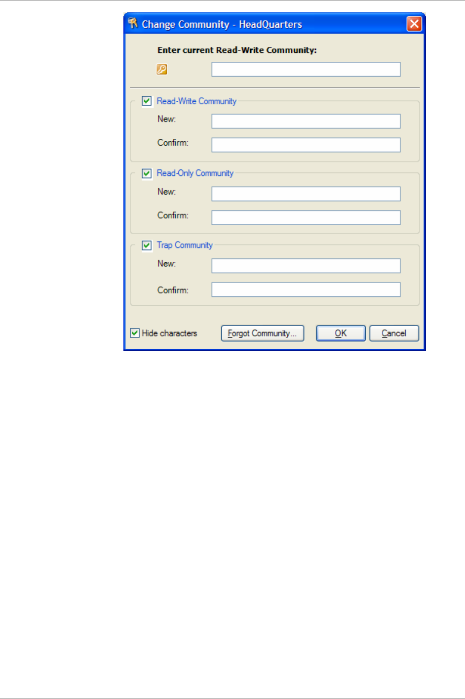
4.12 Changing Community Values
The ODU communicates with the management application using
SNMPv1 protocol. The protocol defines three types of communities:
• Read-Only for retrieving information from the ODU
• Read-Write to configure and control the ODU
• Trap used by the ODU to issue traps.
The community string must be entered at login. The user must know
the password and the correct community string in order to gain access
to the system. A user may have read-only privileges.
It is not possible to manage the ODU if the read-write or the read
community values are forgotten. A new community value may be
obtained from technical support for the purpose of setting new
community; the serial number or the MAC address of the ODU must be
supplied.
4-26 Changing Community Values

WinLink1000 Installation and Operation Manual Chapter 4 Configuration
The manager application and the ODU use the community strings
public-bru1 for the local unit and public-bru4097 for the remote unit.
These are the factory defaults, but can only be used one time on the
first installation.
A new community string must be set when entering the system for the
first time. The read-write community and read-only community have a
minimum of five alphanumeric characters. (Bru1 and bru4097 are not
permitted). Changing the trap community is optional by clicking the
check box.
Note
Editing Community Strings
The community change dialog box is available from the Configuration
> Security tab. Both read-write and read-only communities must be
defined.
On entering for the first time, use netman as the current community.
The community string must be changed when entering the system for
the first time, and the community string netman cannot be used again.
Æ To change a community:
1. From the Configuration dialog box, select the Security tab
2. Type the current read-write community (default is netman).
3. Select the communities to be changed by clicking the check box.
4. Type the new community and re-type to confirm.
5. Click OK to save.
Changing Community Values 4-27
Chapter 4 Configuration WinLink1000 Installation and Operation Manual
Figure
4-18. Changing the Community String
4-28 Changing Community Values
WinLink1000 Installation and Operation Manual Chapter 4 Configuration
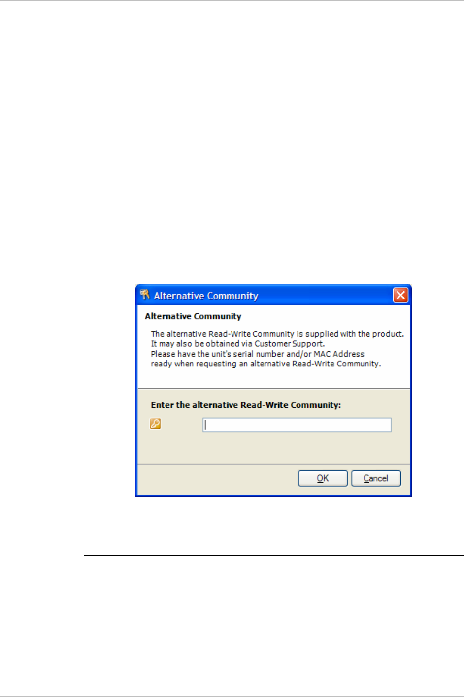
Forgotten Community string
If the read-write community string is unknown, an alternative
community key can be used. The alternative community key is unique
per ODU and can be used only in order to change the community
strings. The alternative community key is supplied with the product,
and it is recommended to keep it safe.
If both the read-write community and the alternative community key
are unavailable, then an alternative community key can be obtained
from customer support using the ODU serial number or MAC address.
The serial number is located on the product, and the MAC address is
displayed in the manager inventory tab.
When you have the alternative community key, click on the Forgot
Community button and enter the Alternative Community (
Figure
4-19
).
Then reconfigure the read-write community string.
Figure
4-19. Alternative Community Dialog box
4.13 Changing Passwords
There are two passwords necessary to use the WinLink1000 system.
The first is encountered when running the management software, the
second, the link Password is used for encryption purposes and is found
when installing or configuring the link.
Changing Passwords 4-29

Chapter 4 Configuration WinLink1000 Installation and Operation Manual
Changing the Management Password
Æ To change the management password
1. From the Tools menu, select Change Password
2. The Change Password dialog box appears.
3. Enter current password, and new password.
4. Click Ok to confirm.
Changing the Link Password
WinLink1000 Radio Link is encrypted using Advanced Encryption
System (AES) using a 128 bit dynamic key. During the installation
process a Link Password must be set. An Initial encryption key is
generated. Each time a link is established the Encryption key is
validated. If the validation failed the link is established but no service
or configuration is allowed. In this state the user can change the link
password of each of the sites.
Æ To change the Link Password:
1. From the Configuration dialog box, select the Security tab
2. Click Change next to the Link Password field box.
The Change Link Password dialog box appears.
3. Enter the current link password.
4. Enter the new password.
5. Enter the new password again in the Confirm box.
Forgotten the Link Password
In case of a forgotten link password, the user may enter the key
password supplied with the product. The key password may be
obtained from customer support after validation of the device serial
number or MAC address. The user may change the link password of
both sides of the link at any time using the Link Configuration Wizard.
4-30 Changing Passwords

WinLink1000 Installation and Operation Manual Chapter 4 Configuration
Æ To enter the key password:
1. From the Configuration dialog box, select the Security tab.
2. Click Change next to the Link Password field box.
The Change Link Password dialog box appears.
3. Click the Forgot Link Password button.
The Key Link Password dialog box appears.
4. Type the key link password.
5. A new link password may now be set.
4.14 Muting the Beeper
The ODU beeper starts beeping as soon as power is supplied, and
continues until the ODUs are aligned and the link established.
It is possible to mute the beeper until the alignment procedure is to be
performed.
Æ To mute the beeper:
1. Click on Configuration in the Menu bar and select the relevant site.
The Configuration dialog box opens.
2. In the Configuration dialog box, click the Buzzer button. The button
toggles between on and off.
3. The Beeper will stop.
Æ To restore the beeper:
1. Click on Configuration in the Menu bar and select the relevant site.
The Configuration dialog box opens.
2. In the Configuration dialog box, click the Buzzer button. The button
toggles between on and off.
3. The Beeper will start.
Muting the Beeper 4-31
Chapter 4 Configuration WinLink1000 Installation and Operation Manual
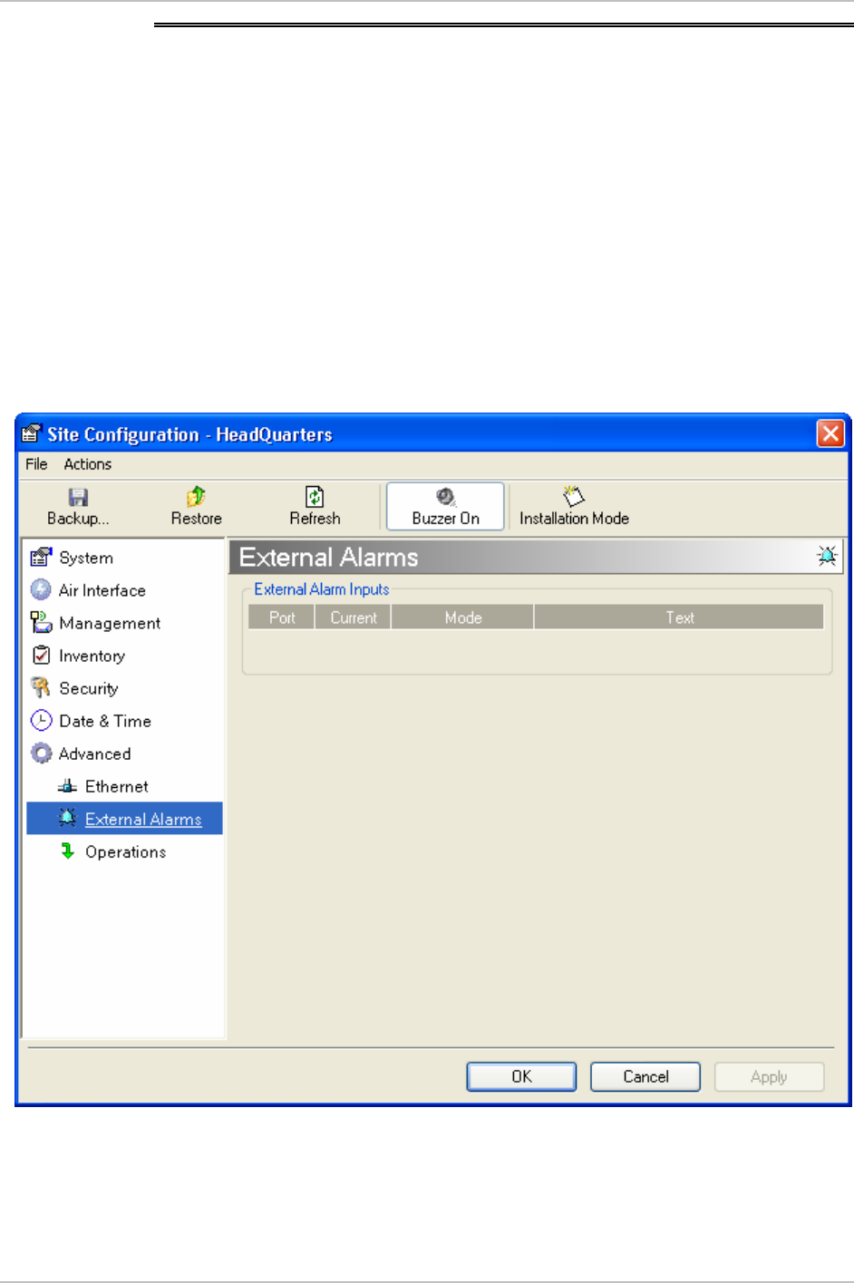
4.15 Setting External Alarm Inputs
The IDU-C has two external alarm inputs in the form of dry-contact
relays. The Alarm interface is located on the front panel of the IDU-C
and is a 9-pin D-type female connector, see
Appendix A
for the
pinout. The user enables or disables each of the alarms and can
configure the text that appears in the alarm trap. The ODU sends the
alarm within less than a second from actual alarm trigger.
Æ To set the external alarm inputs:
1. Open the Site Configuration Alarms configuration by clicking
Configuration > Advanced.
Figure
4-20. External Alarm Configuration
2. Enter a description of the alarms in the fields.
3. Click Apply to save.
4-32 Setting External Alarm Inputs

WinLink1000 Installation and Operation Manual Chapter 4 Configuration
4.16 Managing Configuration Files
Saving WinLink1000 Configuration in a File
WinLink1000 management software allows you to save configuration
parameters of the local and remote units on the management station
as an INI file. Each site is saved in a separate INI file.
Æ To save the configuration in a file:
1. Click Configuration from the main menu.
2. Select which site to backup.
The configuration dialog box opens.
3. Click Backup.
4. In the Save As dialog box, indicate in which folder and under what
name configuration file is to be saved, and click Save.
Restoring a Configuration File
Configuration files (*.ini) can be uploaded from the management
station. Verified configuration files can be distributed to other units
that use the same configuration.
Æ To restore a configuration file:
1. From the Configuration menu, select the site to reconfigure.
The Configuration dialog box opens.
2. Click Restore.
3. From the Open dialog box select *.ini file to upload and click Ok.
4.17 Reinstalling the Link
It may be necessary to reinstall the link if the ODUs should need to be
realigned.
Reinstalling the link causes both sites to go into install mode.
Not
e
Æ To reinstall the link:
4. Click on Configuration in the Menu bar and select any one of the
sites.
Reinstalling the Link 4-33

Chapter 4 Configuration WinLink1000 Installation and Operation Manual
The Configuration dialog box opens.
5. Click the Install Mode button in the Configuration dialog box.
A message box asking if you want to enter install mode appears.
6. Click Yes to continue.
WinLink1000 enters install mode and the beeper starts beeping.
7. Realign the ODUs and complete the Installation wizard (see
Chapter2
).
4.18 Resetting WinLink1000
Resetting the link causes service disconnection.
In order to maintain the link configuration, reset the remote
WinLink1000 first
.
Note
Æ To reset WinLink1000:
1. From Maintenance, reset the remote WinLink1000.
2. From Maintenance, reset the local WinLink1000.
Æ To reset to Factory Defaults
1. Click on Configuration in the Menu bar and select any one of the
sites.
The Configuration dialog box opens.
2. Select Operations in the Configuration dialog box.
3. Click the Restore Defaults button
A message box asking if you want to restore factory default
appears.
4. Click the check box if you want to keep the current IP settings.
5. Click Yes to continue.
4.19 Displaying the Inventory
Æ To view the inventory data
1. Click configuration from the main menu.
4-34 Displaying the Inventory


Chapter 5
Diagnostics and
Troubleshooting
This chapter describes the WinLink1000 diagnostic functions, which
include:
• Monitoring Performance
• Error detection and alarms
• Diagnostic tests (local and remote loopbacks on E1 or T1 link)
• Troubleshooting
• Frequently asked questions.
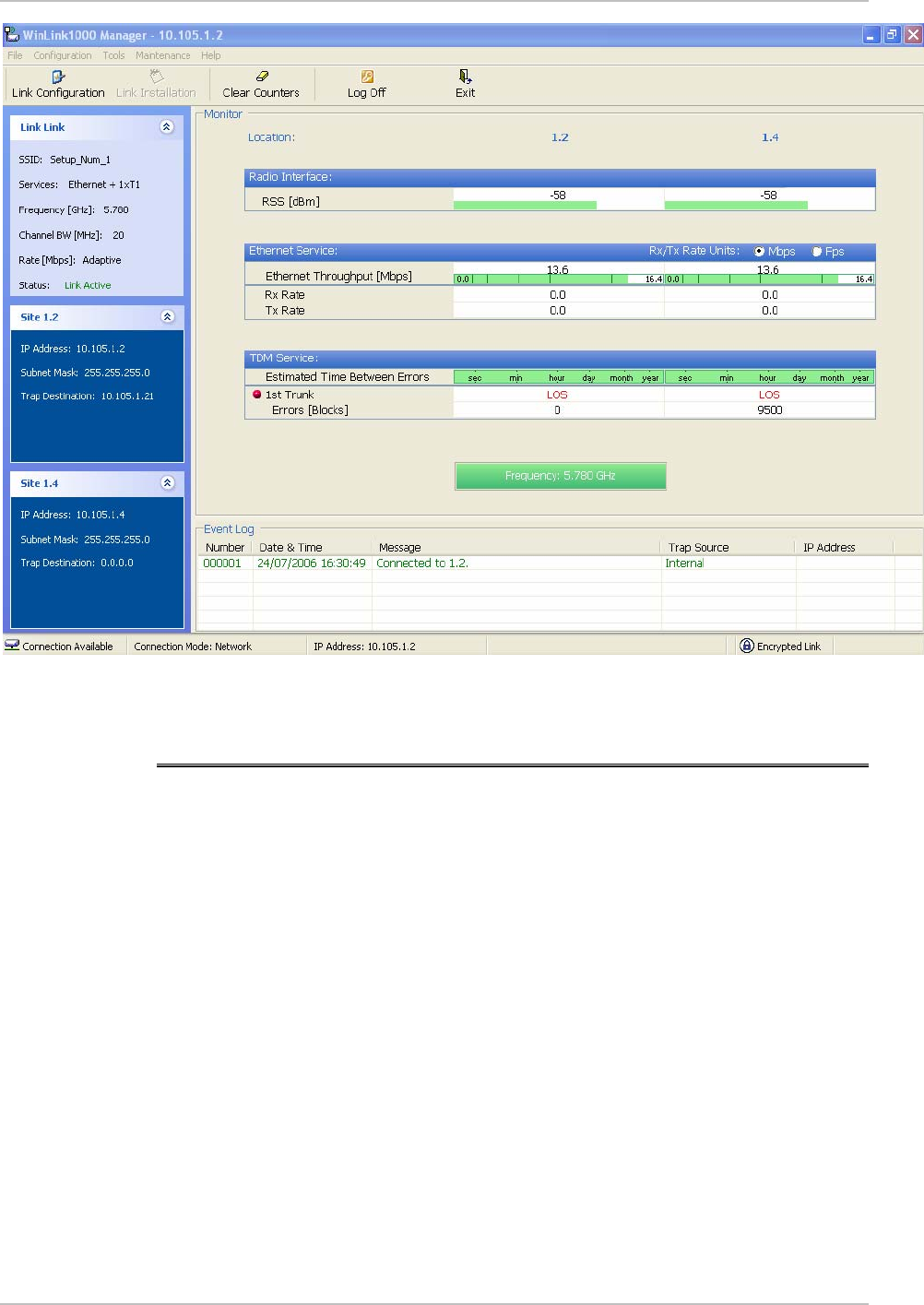
5.1 Monitoring Performance
WinLink1000 constantly monitors traffic over the radio link and collects
the following statistics data:
• Site 1/Site 2 received traffic rate (in kbps)
• Site 1/Site 2 received frames rate (in fps)
• Radio signal strength (in dBm)
• Error (Blocks).
The statistics (monitor) log and event log can be saved as TXT files.
New alarms are automatically added to the text file, as they enter the
event log.
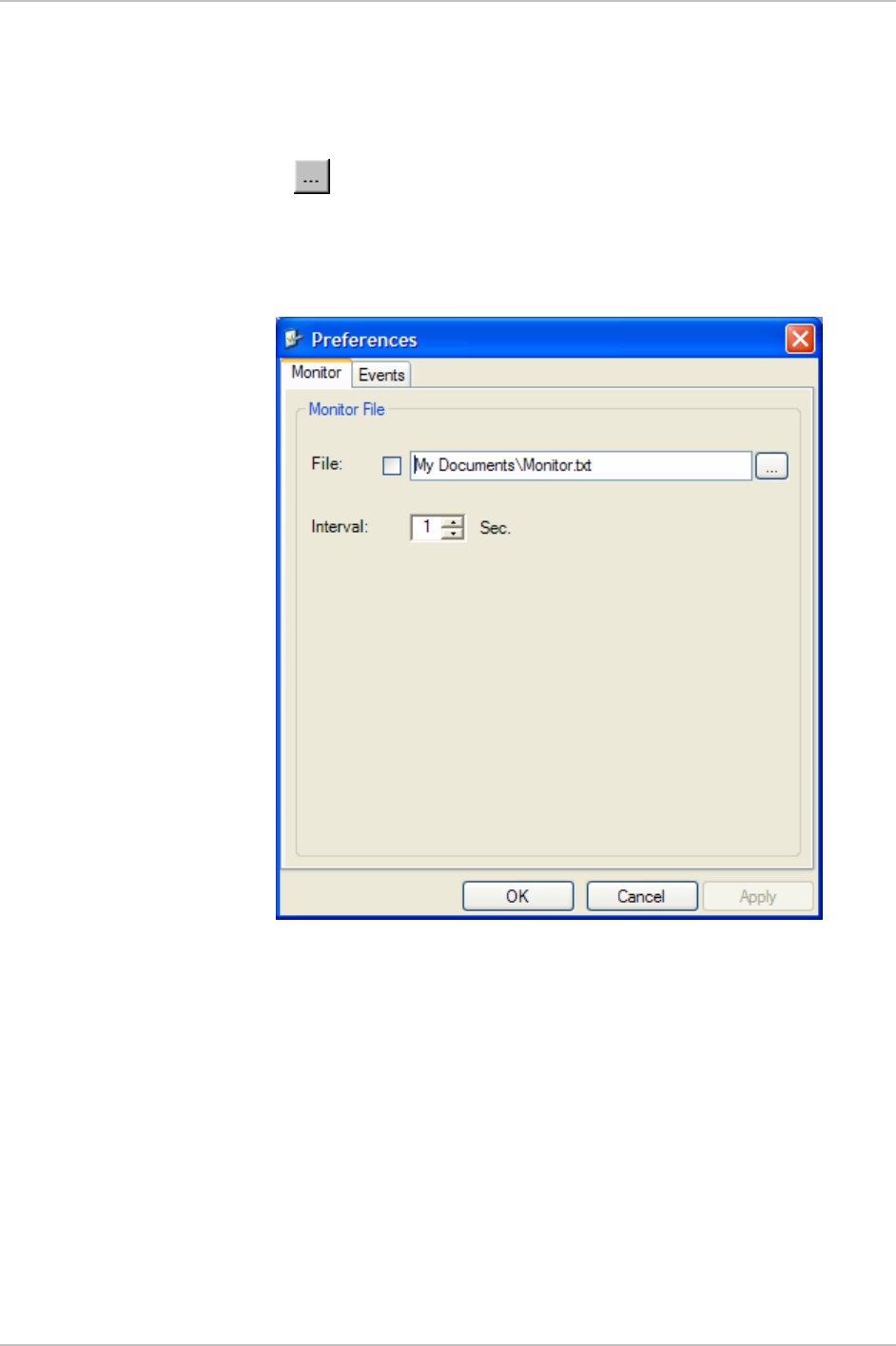
Saving the Monitor Log
Æ To save the monitor log:
1. From the Tools menu, choose Preferences.
The Preferences dialog box appears (see
Figure
5-1
).
Monitoring Performance 5-1
Chapter 5 Diagnostics and Troubleshooting WinLink1000 Installation and Operation Manual
2. Click the Monitor Tab.
3. Select the file to save.
4. Click the check box to open the file for saving.
5. Click the button and in the Select File dialog box indicate in
which folder and under what name the alarm log file is to be saved.
6. Set the time interval for adding data to the file.
7. Click Ok to save the file
Figure
5-1. Preferences Dialog Box, Monitor Tab
Setting the Events Preferences
You can define a color that the traps are displayed in the monitor pane,
according to severity of the event. The severity is predefined.
Æ To set the trap color:
1. From the Tools menu, choose Preferences.
The Preferences dialog box appears).
2. Click the Events Tab (see
Figure
5-2
).
5-2 Monitoring Performance

WinLink1000 Installation and Operation Manual Chapter 5 Diagnostics and Troubleshooting
3. Select the Event priority type and click on the button.
A color chart opens.
4. Select the desired color.
5. Repeat for all the trap types.
Æ To set the trap background color:
• Click Background Color to change the text background.
Æ To reset the trap colors:
• Click Reset Settings to return to the default color settings.
Saving the Events Log
Æ To save the event log:
1. From the Tools menu, choose Preferences.
The Preferences dialog box appears (see
Figure
5-2
).
2. Click the Events Tab.
3. Select the file to save.
4. Click the check box to open the file for saving.
5. Click the button and in the Select File dialog box indicate in
which folder and under what name the alarm log file is to be saved,
and click OK.
Monitoring Performance 5-3
Chapter 5 Diagnostics and Troubleshooting WinLink1000 Installation and Operation Manual
Figure
5-2. Preferences Dialog Box, Event Log Tab
5-4 Monitoring Performance
WinLink1000 Installation and Operation Manual Chapter 5 Diagnostics and Troubleshooting
5.2 Automatic Link Data collection
The Get Link Information feature collects all the link and Manager
information which can be used for diagnostics.
In the event of needing to contact technical support please send this
file so as to speed up the assistance.
Æ To get link information
1. Click Help on the menu bar, select Link Information.
The Get Link Information dialog box appears. See
Figure
5-3
.
2. Click File Path to get to the directory to save the file in.
3. Click Start to save the information.
Figure
5-3. Get Link Information
Automatic Link Data collection 5-5
Chapter 5 Diagnostics and Troubleshooting WinLink1000 Installation and Operation Manual
5.3 Viewing Performance Reports
The Performance Monitor Report opens a window (
Figure
5-4
)
displaying performance views of each of the interfaces1. Several
performance data are collected for each of the interfaces (ES, SES, and
UAS), as well as Specific data per Interface type (e.g., TX and RX bytes
for Ethernet). For the Air Interface, user defined thresholds data are
collected. Refer to
Table
5-1
and
Table
5-2
.
Data is collected and selectively displayed based on three time intervals
as selected by the Interval radio buttons:
• Current (t=0)
• 15 minutes Intervals
• Daily.
Figure
5-4. Performance Monitoring Report window
1 Ethernet performance is not collected in PoE systems.
5-6 Viewing Performance Reports

WinLink1000 Installation and Operation Manual Chapter 5 Diagnostics and Troubleshooting
Table
5-1. Explanation of performance data
Data type Reported value Explanation
UAS – Unavailable
Seconds
Seconds in which the
interface was out of
service.
ES – Error Second The number of
seconds in which there
was at least an error
block. Note that
notation of an error
block is different per
interface.
SES – Severe Error
Second
The number of
seconds in which the
service quality is low
(the actual BBER ratio
varies per interface).
BBE – Background
Block Error
The number of error
block in an interval.
Generic PM Data
Integrity A flag indicating that
the data is valid. Note
that the PM data is not
valid if not all the
values were stored2.
Max RSL The maximum of the
receive signal level
(measured in dBm).
Min RSL The minimum of the
receive signal level
(measured in dBm).
Air Interface PM Data
Max TSL The maximum of the
transmit signal level
(measured in dBm)3.
2 Possible reasons are: Clock changes within the interval and Power up reset
3 The transmit power is fixed. The value can be changed only by user
configuration
Viewing Performance Reports 5-7

Chapter 5 Diagnostics and Troubleshooting WinLink1000 Installation and Operation Manual
Data type Reported value Explanation
Min TSL The minimum of the
transmit signal level
(measured in dBm).
RSL Threshold 1 This parameter counts
the number of seconds
in which the RSL is
below the specified
threshold.
RSL Threshold 2 This parameter counts
the number of seconds
in which the RSL is
below the specified
threshold.
TSL Threshold 1 This parameter counts
the number of seconds
in which the RSL is
above the specified
threshold.
BBER Threshold The BBER Threshold
value counts the
number of seconds in
which the Background
Block Error Ratio
(BBER) exceeds the
specified threshold.
Note, that the system
is design for excellent
quality of service with
BBER of less then 1%.
(at 1% BBER expected
TDM BER is less than
1E-6.
Ethernet Interface PM
Data
Received Bytes The number of Mega
bytes received in the
specified port within
the interval
5-8 Viewing Performance Reports
WinLink1000 Installation and Operation Manual Chapter 5 Diagnostics and Troubleshooting
Data type Reported value Explanation
Transmitted Bytes The number of Mega
bytes received in the
specified port within
the interval.
Table
5-2. Action of the tool bar button commands
Button Action
Get Data Uploads the selected report from the ODU.
Save Saves the data in a CSV or Text format for additional analysis.
Clear Removes the current data from the window.
Selection
pane
Selects the site, interface, and interval to be displayed.
Threshold Opens the threshold configuration dialog box (Figure 5-5) to set the Air
Interface thresholds. Note that threshold change is effected
immediately, but it does not change any historical data.
Close Closes the Performance Monitor Report window.
Figure
5-5. Threshold configuration dialog box
5.4 Error Detection and Alarms
WinLink1000 detects fault conditions of the radio and user links and
initiates alarms to alert the user.
Error Detection and Alarms 5-9

Chapter 5 Diagnostics and Troubleshooting WinLink1000 Installation and Operation Manual
To store the event log, first define the IP address, subnet mask, default
gateway and trap address of the management PC, see
Chapter 4
for
details.
Note
Alarms (traps) are displayed in the Event Log in the lower panel of the
Main Menu screen. The alarm log is saved as a TXT file.
The event log includes the following fields:
• Sequential number (ID)
• Date and time stamp
• Message
• Trap source
• IP address of the ODU that initiated alarm.
5-10 Error Detection and Alarms

WinLink1000 Installation and Operation Manual Chapter 5 Diagnostics and Troubleshooting
Table
5-3. WinLink1000 Alarms and Information Messages
Message Description
Radio Link – Sync Radio link is synchronized
Radio Link – Out Of Sync Radio link lost synchronization
Link Has Been Reset ODU was reset due to internal problem
TDM Interface – Normal TDM interface is operating properly
TDM Interface – LOS Loss of Synchronization is reported by TDM interface
TDM Interface – LOS Loss of Signal is reported by TDM interface
TDM Interface – AIS Alarm Indication Signal is reported by TDM interface
TDM Interface – Loopback A loopback is active on TDM interface
Link Resetting Wireless link reset from the management station. This
alarm is caused by automatic reset after link
configuration.
Local ODU Resetting The local ODU reset from the management station.
Monitor was stopped since no
connection to the link
No ODU-to-IDU traffic was detected during the last 20
minutes.
TDM Service – Normal TDM service is operating properly
TDM Service – Alarm Error has been detected on a TDM line
Configuration problem detected The link needs to be reinstalled
Channel Scanning in progress The ODU is scanning the channels for the remote ODU
Transmitting on <frequency>
GHz
The ODU is transmitting on the frequency channel listed
Radar activity was detected in
<site>, on channel <frequency>
GHz
For DFS versions only. Radar is detected; the channel is
prohibited for 30 minutes.
Monitoring fo Radar activity on
channel <frequency> GHz
For DFS versions only. ODU is looking for Radar activity.
Bit Failed indication Indicates ODU hardware problem. Send error code to
Technical Support.
Æ To view summary of saved alarms
• From the Tools menu, choose Active Alarm Summary.
Error Detection and Alarms 5-11

WinLink1000 Installation and Operation Manual Chapter 5 Diagnostics and Troubleshooting
Figure
5-6. Active Alarms Summary
Table
5-4. Active Alarms command buttons
Command Action
Save Saves the alarms in CSV or text format for further
analysis.
Refresh Reads the alarms from the ODU, and displays the
alarms.
Site Selects site for the active alarms.
Close Closes the active alarm window.
Error Detection and Alarms 5-13
Chapter 5 Diagnostics and Troubleshooting WinLink1000 Installation and Operation Manual
5.5 Testing WinLink1000
WinLink1000 supports activation of the internal and external loopbacks
on the local and remote units.
Æ To activate a loopback:
1. From the Maintenance menu, choose Set Loopbacks.
The Loopbacks dialog box appears (see
Figure
5-7
).
2. From the Local or Remote drop-down box, select a loopback that
you intend to run, and click OK.
A confirmation message appears.
3. Click OK to activate a loopback.
WinLink1000 activates selected loopback. A loopback status
arrow in the Main menu turns green to indicate an active
loopback.
Æ To deactivate a loopback:
• From the From the Local or Remote drop-down box of the
Loopbacks dialog box, select None and click OK.
A loopback is deactivated and the corresponding status arrow in
the Main menu becomes dimmed.
Figure
5-7. Loopbacks Dialog Box
5-14 Testing WinLink1000
WinLink1000 Installation and Operation Manual Chapter 5 Diagnostics and Troubleshooting
Local External Loopback
Local WinLink1000 can be set to an external loopback to test the local
E1/T1 port and its connection to the local side user equipment. In this
mode, data coming from the local user equipment is looped back to it
(see
Figure
5-8
). This loopback is initiated from a management station
connected to the local unit.
Tes ti ng
Equipment
Management
Station
E1
Interface
/T1
Local ODU
Figure
5-8. Local External Loopback
Remote Internal Loopback
Remote WinLink1000 can be set to an internal loopback to test
connection between the local and remote units, the local E1/T1 port
and its connection to the local side user equipment. In this mode, data
coming from the local WinLink1000 is looped back to it (see
Figure
5-
9
). This loopback is initiated from a management station connected to
the local unit.
Management
Station
E1/T1
Interface E1
Interface
/T1
Tes ti ng
Equipment
Remote ODU Local ODU
Figure
5-9. Remote Internal Loopback
Remote External Loopback
Remote WinLink1000 can be set to an external loopback to test the
remote E1/T1 port and its connection to the remote side user
equipment. In this mode, data coming from the remote user equipment
is looped back to it (see
Figure
5-10
). This loopback is initiated by an
Testing WinLink1000 5-15
Chapter 5 Diagnostics and Troubleshooting WinLink1000 Installation and Operation Manual
inband command sent from a management station connected to the
local unit.
Testi ng
Equipment
Management
Station
E1
Interface
/T1 E1
Interface
/T1
Local ODU
Inband Loopback
Activation Command
Remote ODU
Figure
5-10. Remote External Loopback
Local Internal Loopback
Local WinLink1000 can be set to close an internal loopback to test
connection between the local and remote units, remote E1/T1 port and
its connection to the remote side user equipment. In this mode, data
coming from the remote user equipment is looped back to it (see
Figure
5-11
). This loopback is initiated by an inband command sent
from a management station connected to the local unit.
Tes ti ng
Equipment
Management
Station
Local ODU
Inband Loopback
Activation Command
Remote ODU
E1/T1
Interface E1
Interface
/T1
Figure
5-11. Local Internal Loopback
5.6 Troubleshooting
Use
Table
5-6
and
Table
5-6
to diagnose any faults in the system.
Table
5-5. Troubleshooting
Symptom Remedy
No power Verify that AC power is connected to the IDU.
5-16 Troubleshooting

WinLink1000 Installation and Operation Manual Chapter 5 Diagnostics and Troubleshooting
Verify that the ODU cable is properly wired and
connected.
Complete the installation procedure from the
management software.
No signal
Verify the ODU alignment. Check that the radio
configuration of both site A and site B units are the
same (channel and SSID).
Weak signal Verify the ODU alignment, reconfigure the link.
Verify the beeper sounds the Best Signal sequence.
The WinLink1000 LEDs show faults in the system or the link.
Table
5-6. Troubleshooting with WinLink1000 LEDs
LED Status Remedy
PWR Off Check that AC adapter is connected to the
IDU-E and the AC power outlet.
IDU Orange Check that the IDU/ODU cable is properly
wired and connected.
ODU Red Check that the IDU/ODU cable is properly
wired and connected.
Orange Complete the installation procedure from
the management software.
AIR I/F
Red Check the ODU Antenna alignment. Check
that the radio configuration of both site A
and site B units are the same (channel and
SSID).
Off Check the TDM service configuration in the
NMS.
Orange Check that the system is not in loopback
mode.
Check the site B IDU ports and cables and
site B external equipment.
SERVICE
Red Check the site A IDU ports, cables and
external equipment.
Troubleshooting 5-17

Chapter 5 Diagnostics and Troubleshooting WinLink1000 Installation and Operation Manual
5.7 Frequently Asked Questions
Q: What performance issues will arise due to environmental conditions?
A: WinLink1000 is not sensitive to environmental conditions. However
if heavy rain or snowfall is expected ensure the performance by
allowing a higher fade margin in the link budget planning calculations.
Q: When using the WinLink1000, what is the potential for interference
between our system and other cellular or wireless Networks devices?
A: The WinLink1000 is a robust system. However since it operates in
unlicensed band there maybe some interference. Nevertheless, the fact
that we can manually set the frequency gives us the flexibility to find a
clear channel. In addition each WinLink1000 link uses unique user
configurable SSID code.
Q: What protocol does the WinLink1000 use, i.e. 802.11?
A: WinLink1000 uses a proprietary protocol; this protocol contains
improved options that more efficiently support the clock
reconstruction from the TDM services.
Q: What type of security is offered on WinLink1000?
A: WinLink1000 has three levels of security:
1. AES hardware mechanism
2. Each unit uses a unique SSID link-specific code (up to 24
alphanumeric characters)
3. Proprietary protocol protects from eavesdropping from other
systems.
Q: Can we use horizontal and vertical polarization on the same
frequency to double the number of wireless links?
A: Installing two WinLink1000 systems in the same band with cross
polarization provides 20–25 dB separations. Nevertheless, since there
are reflections, the cross polarization separation is decreased and
spatial separation is recommended.
Q: Could you add the frequency of 5.735 to the manual selection in
order to increase the number of 20 MHz channels to six?
5-18 Frequently Asked Questions

WinLink1000 Installation and Operation Manual Chapter 5 Diagnostics and Troubleshooting
A: Currently the system provides fixed channels, with one manual
frequency setting. The manual setting provides flexibility of spectrum
selection, including 5.735 MHz.
Q: Can we mange WinLink1000 using SNMPc other than the supplied
management software that comes with the units?
A: Yes. The WinLink1000 is SNMP-based. WinLink1000 can be
managed when using other SNMP software after implementing RADWIN
MIB’s.
Q: Can WinLink1000 be managed and configured via Telnet?
A: No. Use only the WinLink1000 software manager.
Q: Can I use WinLink1000 with any vendor’s external antenna?
A: Yes. RADWIN supplies the WinLink1000 external ODU with an N-
type typical connector. Any vendor’s external antenna that can be
cascaded to our external unit can be used without problem. Please
note that dB losses in the cascading cable between the external ODU
and antenna should be taken into consideration. (In the supplied
cascading cable of one meter we have 1 dB loss)
Q: Do we need to add external arrestors on WinLink1000 cables?
A: The WinLink1000 ODU includes arrestors and lightning protection.
Therefore there is no need to add additional arrestors.
Q: What is the actual Ethernet data rate and maximum throughput?
A: The maximum net throughput of WinLink1000 is full duplex 18
Mbps.
Note
WinLink1000 is a symmetrical system
Q: What is the sensitivity for each rate of the WinLink1000?
A: The rate sensitivities are:
Rate
[Mbps]
Sensitivity
[dB]
12 -84
18 -81
36 -74
Frequently Asked Questions 5-19

Chapter 5 Diagnostics and Troubleshooting WinLink1000 Installation and Operation Manual
Rate
[Mbps]
Sensitivity
[dB]
48 -68
Q: Does WinLink1000 withhold any MAC Addresses?
A: The WinLink1000 is a layer 2 Bridge (VLAN transparent). The built-in
switch contains a MAC Address table up to 2047.
Q: Can I use any category 5e cable in order to connect the IDU and
ODU?
A: The cable should be suitable for outdoor use, and shielded Category
5e.
Q: What are the BER values expected in the WinLink1000 link?
A: 10-11 (according to BER sensitivity threshold)
Q: Does WinLink1000 use DSSS technique?
A: No, WinLink1000 uses the advanced OFDM technique.
Q: What are the main advantages of the WinLink1000 solution (e.g.,
wireline, wireless, etc.) over other possible alternatives?
A:
• Easy and intuitive installation using audio indication.
• Easy configuration using the management software of overall link
site-to-site, there is no need to travel between the two sites in
order to change the configuration.
• Easy migration between transition channels site-to-site.
• Full backup option – backup and restore using ini files.
• Very light ODU (1.5 kg).
• No RF loses between IDU and ODU.
• Robust Air Interface Layer 2 ARQ insures “error-free” Ethernet
service even in harsh conditions. Retransmit mechanism for TDM
esures low BER.
• Integrated up to 4 E1/T1 and Ethernet radio over one single
product.
5-20 Frequently Asked Questions

WinLink1000 Installation and Operation Manual Chapter 5 Diagnostics and Troubleshooting
• Supports a variety of applications Voice and Data over single radio –
no need for external mediation device.
• Smooth migration to VoIP applications.
• Carrier class compliant with ITU standards for E1 and T1.
• Low and constant TDM latency (8 msec).
• Extremely accurate recovered clock low cost replacement to PDH
radios.
5.8 Technical Support
Technical support for this product can be obtained from the local
distributor from whom it was purchased.
For further information, please contact the RADWIN distributor nearest
you or one of RADWIN's offices worldwide. This information can be
found at www.radwin.com.
Technical Support 5-21

Appendix A
Wiring Specifications
A.1 ODU-IDU Cable
The ODU-IDU cable is standard CAT-5, 4 twisted-pair 24 AWG FTP,
terminated with RJ-45 connectors on both ends. It is covered by a
cable gland on the ODU side for hermetic sealing.
Table
A-1
shows the connector pinout.
Table
A-1. ODU-IDU Cable Connector Pinout
IDU RJ-45 Wire Color Function ODU RJ-45
1
twisted
White/Green Ethernet (RxN) 1
2 pair Green Ethernet (RxT) 2
3
twisted
White/Orange Ethernet (TxT) 3
6 pair Orange Ethernet (TxN) 6
4
twisted
Blue Power (+) 4
5 pair White/Blue Power (+) 5
7
twisted
White/Brown Power (−) 7
8 pair Brown Power (−) 8
ODU-IDU Cable A-1
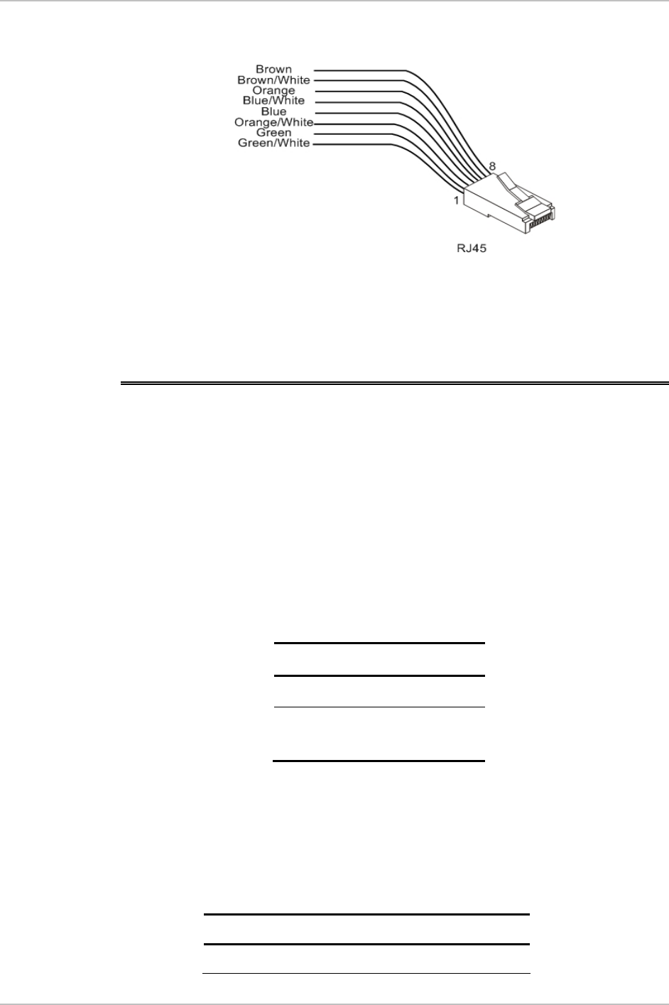
Appendix A Wiring Specifications WinLink1000 Installation and Operation Manual
Figure
A-1. RJ-45 wiring for IDU-ODU cable
A.2 User Port Connectors
The IDU includes ports for connecting E1/T1 and 10/100BaseT
Ethernet user devices.
Trunk Port
The Trunk (E1/T1) interface terminates in an 8-pin RJ-45 balanced
connector, wired in accordance to
Table
A-2
.
Table
A-2. E1/T1 Connector Pinout
Pin Function
4,5 Receive (input)
1,2 Transmit
(output)
LAN Port
The LAN 10/100BaseT interface terminates in an 8-pin RJ-45
connector, wired in accordance to
Table
A-3
.
Table
A-3. Fast Ethernet Connector Pinout
Pin Signal Function
1 TD (+) Transmit Data
A-2 User Port Connectors

WinLink1000 Installation and Operation Manual Appendix A Wiring Specifications
(positive)
2 TD (–) Transmit Data
(negative)
3 RD (+) Receive Data
(positive)
6 RD (–) Receive Data
(negative)
A.3 IDU-C Connectors
IDU-C DC Power Terminal
Table
A-4. Terminal Block 3-pin -48VDC
Pin Connection
Right +
Center Chassis
Left –
IDU-C Connectors A-3
Appendix A Wiring Specifications WinLink1000 Installation and Operation Manual
IDU-C Alarm Connector
Table Table A-5 lists the alarm connector pinout.
Table
A-5. Alarm Connector (Dry-Contact)
Pin Description
1 Input 1 Positive
6 Input 1 Negative
2 Input 2 Positive
7 Input 2 Negative
3 Output 1 Normally
Closed
8 Output 1 Common
4 Output 1 Normally Open
9 Output 2 Common
5 Output 2 Normally Open
9COM
8COM
7- ve
6-ve
4
3
1
2
+ve
Output 2
Output 1
Input 1
Input 2
Alarm Connector
7
+ve
10 to 50 VDC alarm voltage
-10 to -50 VDC alarm voltage
Ext. current limit resistor Alarm LED
Ext. DC Power
Alarm Buzzer
Ext. DC Power
Ext. current limit resistor
N/C
N/O
N/O
Figure
A-2. Example for connecting the alarm connector
A-4 IDU-C Connectors
Appendix B
Mast and Wall Installation
B.1 Mounting the ODU
The ODU can be mounted on a mast or a wall.
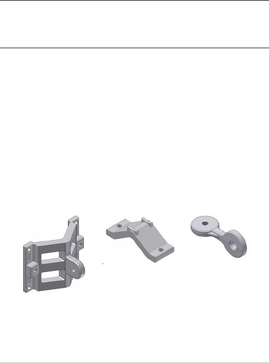
ODU Mounting Kit Contents
The ODU mounting kit includes the following items:
• One Large Clamp (see figure B-1)
• One Small Clamp (see figure B-2)
• One Arm (see figure B-3)
• Four Screw hex head M8x40
• Two Screw hex head M8x70
• Four Washer flat M8
• Three Washer spring M8
• Two M8 Nuts
Figure
B-1. Large
Clamp
Figure
B-2. Small
Clamp
Figure
B-3. Arm
Mounting the ODU B-1
Appendix B Mast and Wall Installation WinLink1000 Installation and Operation Manual
Mounting WinLink 1000 on a Mast
B-2 Mounting the ODU
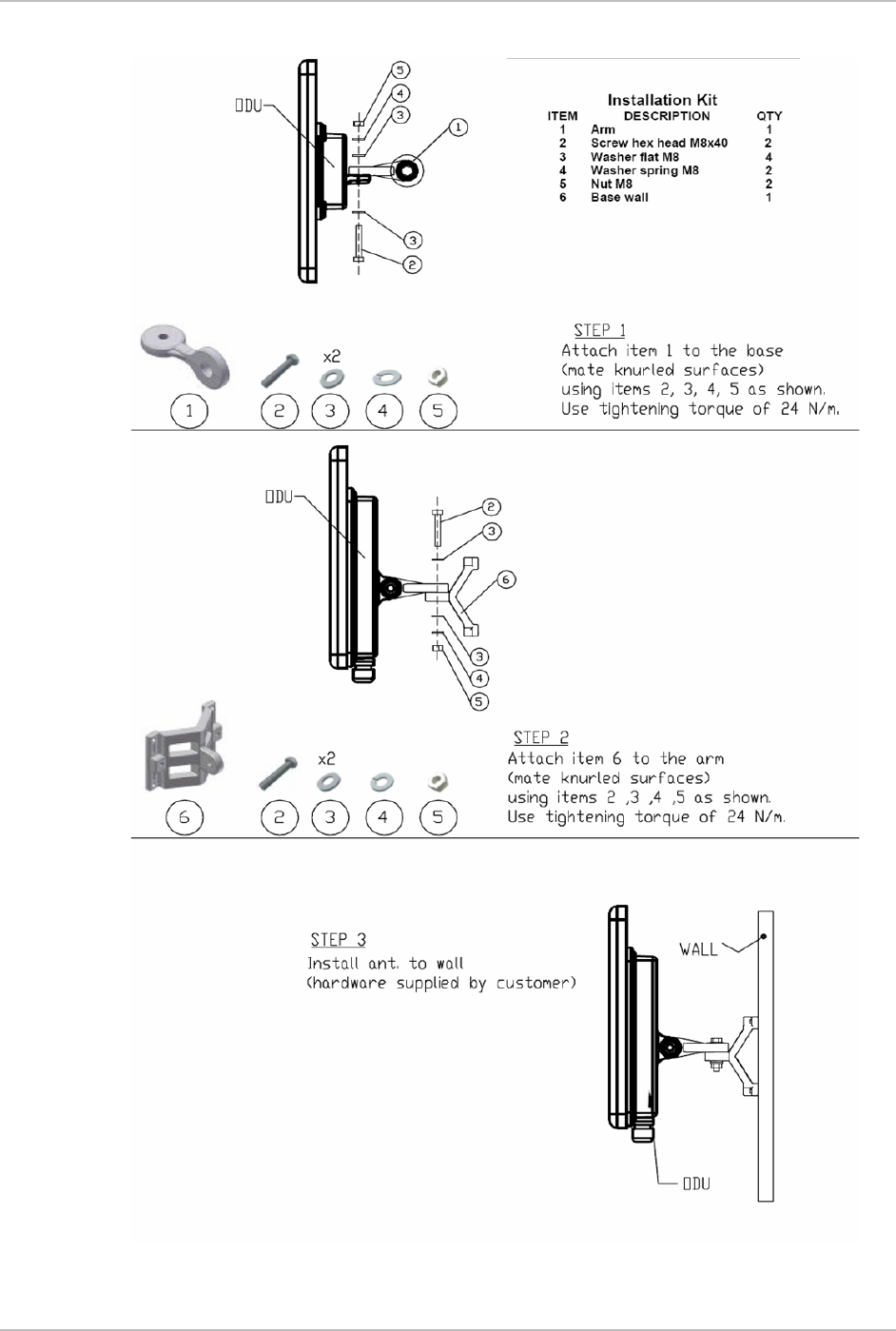
WinLink 1000 Installation and Operation Manual Appendix B Mast and Wall Installation
Mounting WinLink1000 on a Wall
Mounting the ODU B-3

Appendix B Mast and Wall Installation WinLink1000 Installation and Operation Manual
B.2 Mounting an External Antenna
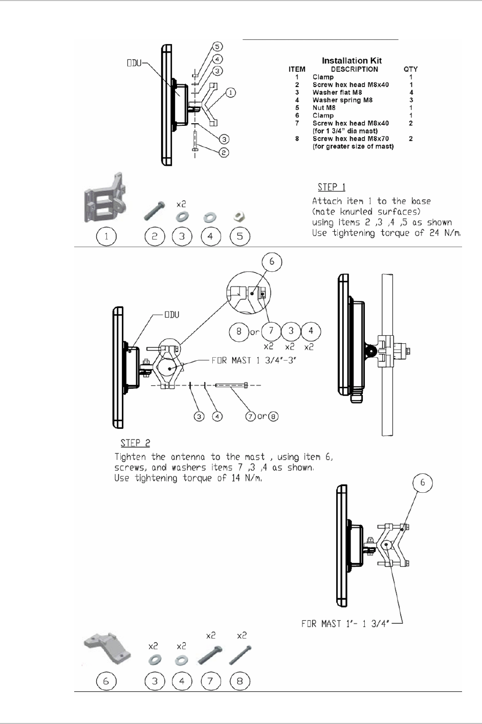
The optional external antenna can be mounted on a mast.
External Antenna Mounting Kit Contents
The external antenna mounting kit includes the following items:
• Twelve flat washers
• Eight spring washers
• Eight hex nuts
• Four bolts
• One U-bracket
• One pivoting bracket
• Two metal strap clamps.
Î To install external antenna on the mast:
1. Attach the U-bracket to the back of the antenna using four flat
washers, four spring washers and four hex nuts.
2. Attach the pivoting bracket to the U-bracket using eight flat
washers, four spring washers, four hex nuts and four bolts.
3. Pass both strap clamps through the vertical slots in the pivoting
bracket.
4. Attach the antenna to the mast using the two strap clamps.
5. Adjust the required tilt using the angular scale and tighten all bolts
and nuts at the required position.
B-4 Mounting an External Antenna

Appendix C
Link Budget Calculator
C.1 Overview
The Link Budget Calculator is a utility for calculating the expected
performance of the WinLink 1000 wireless link and the possible
configurations for a specific link range.
The utility allows you to calculate the expected RSS of the link, and find
the type of services and their effective throughput as a function of the
link range and deployment conditions.
The Link Budget Calculator is supplied on the WinLink 1000 Manager
CD. After installation, it may also be accessed from the menu bar of
the WinLink Manager (see Figure C-1).
Overview
Link Budget Calculator WinLink1000 Installtion and Operation Manual
Figure
C-1. Accessing the Link Budget Manager Calculator
C.2 Using the Link Budget Calculator
The Link Budget Calculator comprises of one table where all the link
parameters are defined.
Using the Link Budget Calculator
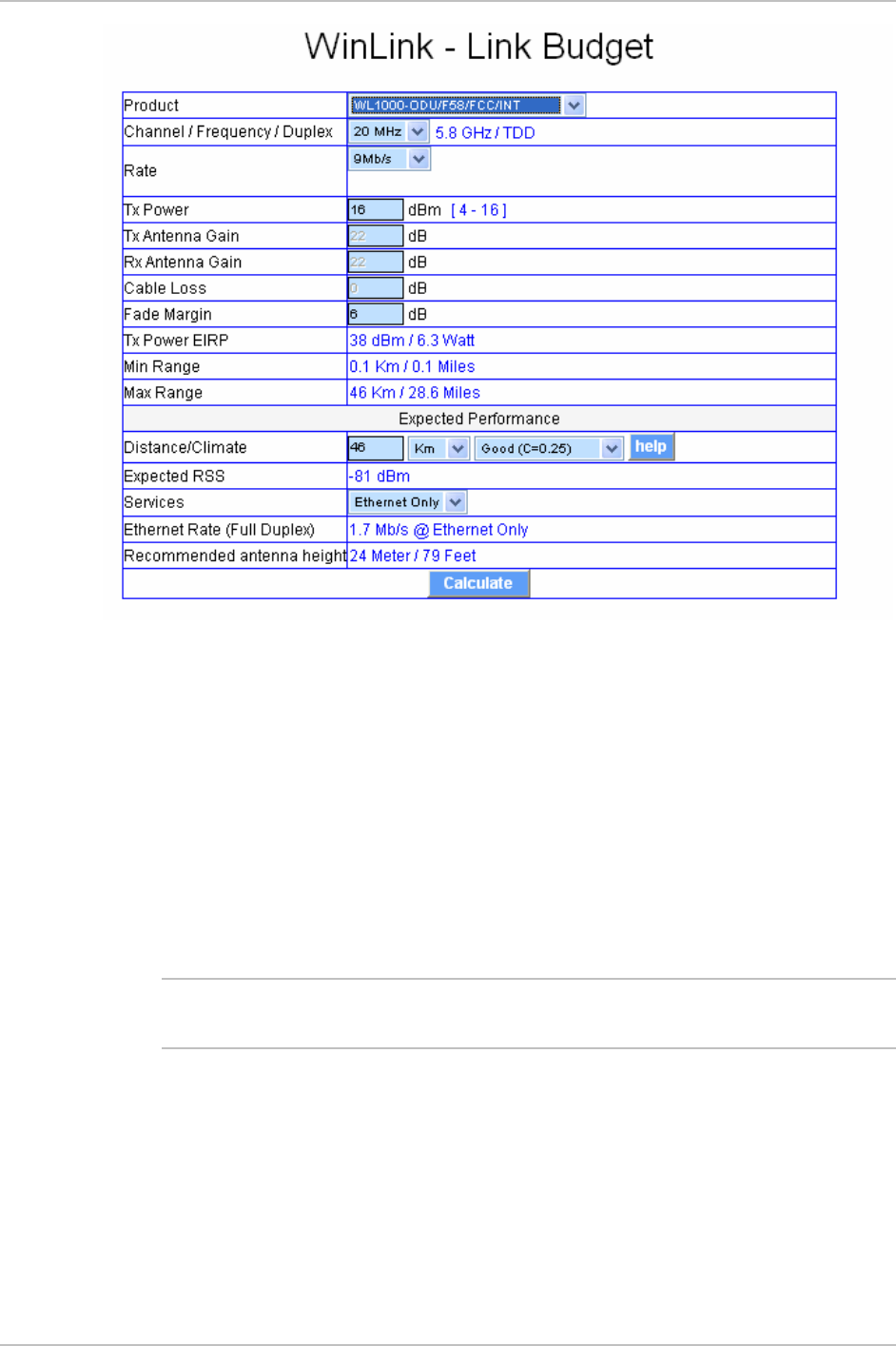
WinLink1000 Installation and Operation Manual Link Budget Calculator
Figure
C-2. Link Budget Screen
Î To calculate the link budget
1. Select your WinLink system product from the dropdown list of
products.
2. Select the rate from the dropdown list. The rate defines the air-
interface rate in Mbps. The system operates in TDD mode and has
overhead of the air-interface protocol and therefore the accurate
actual throughput is provided in the ‘Service’ Row and the effective
Ethernet throughput is provided in the ‘Ethernet Rate’.
Note Throughput can be decreased as a function of range due to
propagation delay.
The remaining fields are completed automatically depending on the
product selected in the product field. Standard WinLink1000 system
parameters are entered as default. Fields in blue boxes may be
edited if non-standard antennas and cables are used.
The Fade margin is the minimum margin that is required for LOS
conditions. For degraded link conditions, a larger fade margin
should be taken into account.
Using the Link Budget Calculator

Link Budget Calculator WinLink1000 Installtion and Operation Manual
The Tx power EIRP for the system is given in dBm and Watts.
3. Select the required link distance and units of distance, kilometers
or miles.
4. Click Calculate
The Expected Performance parameters are calculated and
displayed in the lower part of the table.
Expected RSS – this is the number that the WinLink1000
Manager software shows when the WinLink1000 ODUs are
best aligned.
Services – Maximum E1/T1 services possible whilst
maintaining full duplex Ethernet throughput.
Ethernet Rate – Maximum throughput available with the
chosen system.
5. If the expected performance is not suitable for your application,
select a different data rate and re-calculate.
Using the Link Budget Calculator
Appendix D
AIND Antenna Alignment
Procedure
Use this procedure when using the all indoor system WinLink1000-
ANID or manually aligning two WinLink1000 units.
To achieve the best benefit and link budget from the WinLink
installation, the link antennas must be aligned; the two antennas
should exactly face each other.
In order to achieve the best performance, the line of sight must be as
clear as possible with no obstructions between the two sites.
Prior to attempting WinLink alignment, install the hardware and
software in accordance with the WinLink1000 Installation and
Operation Manual.
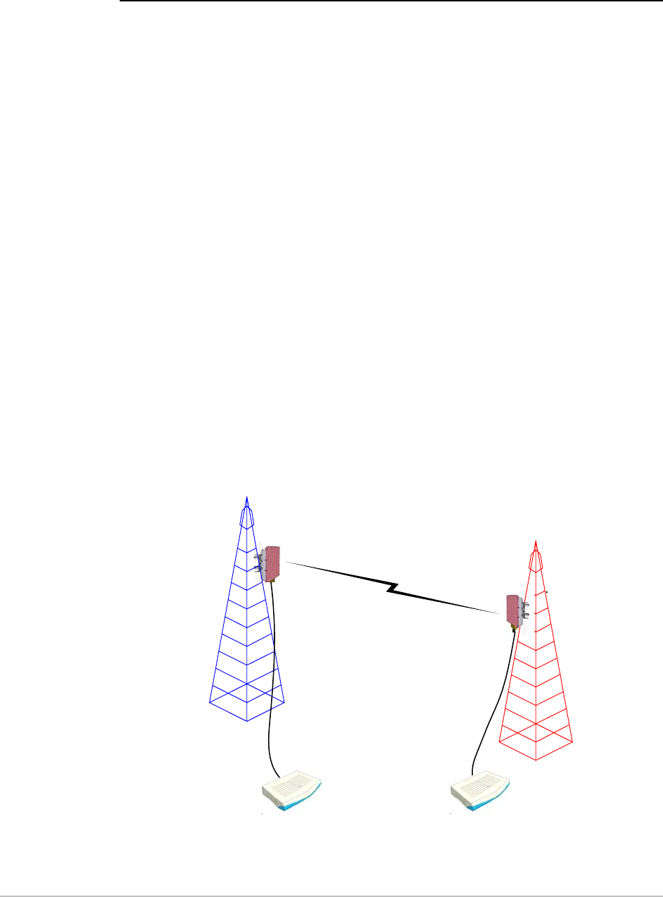
Figure
D-1
shows the link setup. At least two
people are needed to perform the alignment procedures.
Once the alignment is complete, you are able to evaluate the quality of
the link.
Site A
Site B
AirMux
IDUx IDUx
Figure
D-1. WinLink1000 Link Setup
Expected Signal Level D-1

Appendix D AIND Antenna Alignment Procedure WinLink1000 Installation and Operation Manual
D.1 Expected Signal Level
Based on the link budget parameters of the actual WinLink sites, you
need to calculate the expected signal level that will be received by the
receiving site.
Use the Link Budget Calculator utility supplied on the WinLink1000
Manager Software CD-ROM to calculate the expected performance of
the WinLink1000 wireless link. The utility allows you to determine the
RSS of the link, and find the number of E1/T1 services available at
various data rates, with the minimum and maximum distance.
D.2 Performing WinLink1000-AIND Alignment
The supervisor of the antenna alignment is situated at the receive site
with the Spectrum Analyzer.
Equipment Setup
Æ To set up the antenna alignment equipment:
1. Coarsely align the two antennas. Use the compass readings taken
during the Site Survey to point the antennas in the correct direction.
2. Connect the equipment as shown in
Figure
D-1
but connect a
spectrum analyzer in place of the remote WinLink1000-AIND.
3. Turn on the CW transmit signal from site A (from the WinLink1000
NMS).
4. 4. At site B, tune the SA to the frequency transmitted.
5. 5. Increase the SA sensitivity according to the expected receive
signal.
Align the antennas:
Note
•
When one antenna is moved, the opposite ite is passive s
•
Move the antennas very slowly
1. Slowly move the site B antenna azimuth axis (the elevation axis
should be locked) until you see the best signal on the SA Lock the
azimuth axis.
D-2 Performing WinLink1000-AIND Alignment

WinLink1000 Installation and Operation Manual Appendix D AIND Antenna Alignment Procedure
2. Slowly move the site A antenna azimuth axis (the elevation axis
should be locked) until you see the best signal on the SA.
Lock the azimuth axis.
3. Slowly move the site B antenna elevation axis (the azimuth axis
should be locked) until you see the best signal on the SA.
Lock the elevation axis.
4. Slowly move the site A antenna elevation axis (the azimuth axis
should be locked) until you see the best signal on the SA.
Lock the elevation axis.
5. Repeat steps 1 to 4 until the reading on the SA is equal or as close
as possible to the calculated receive signal (for Rx Power Level see
Expected Signal Level
).
When the SA reads the expected receive signal, the antennas are
aligned and there is an indication of a good link between the sites.
6. Tighten the antenna azimuth axis and elevation axis.
7. Stop the CW function. The NMS will restart the system.
8. Connect WinLink1000-AIND unit to external antenna. See
WinLink1000 Installation and Operation Manual for details. The
operational link is shown in
Figure 2-3
.
9. Configure WinLink1000 NMS at both sites to operate at the pure
channel frequency found in the RF survey. WinLink1000 is now
ready for operation.
D.3 Configuring the Link
1. Run the Installation Wizard in the WinLink1000 Manager Software to
set the configuration of the link. Configure the link in accordance
with the parameters calculated in the Link Budget Calculator.
2. WinLink1000 has a unique identification number, the SSID. Each
side of the link looks for its partner with the same SSID. Therefore
both sides of the link must be configured with the same SSID.
3. The WinLink1000 link is now ready for operation.
Configuring the Link D-3

Appendix D AIND Antenna Alignment Procedure WinLink1000 Installation and Operation Manual
D.4 Evaluating the Link
With the link operating at a pure channel as determined by the
RF survey procedure, the recommended performance threshold of an
WinLink1000 link is the following:
RSS: –84 dBm minimum
There are cases when there is no line of sight, but still the link is of an
acceptable quality.
If the link is not within the acceptable limit, see
Troubleshooting
.
D-4 Evaluating the Link

WinLink1000 Installation and Operation Manual Appendix D AIND Antenna Alignment Procedure
D.5 Troubleshooting
If the link is not within the acceptable limit as defined in
Evaluating the
Link
, check the following:
• Verify that both antennas have the same polarization
(horizontal/vertical).
• Check all the WinLink1000-AIND cable connectors for faulty
connections.
• Verify that there are no obstacles in the Fresnel zone of the antenna
path such as large buildings, trees, etc.
• Use a spectrum analyzer with suitable sensitivity to measure the
signal at the distance between the sites.
If nothing improves the receive power level, check the overall link.
• Reduce the distance of the link–move the equipment from one site
closer to the other site–where it is possible to actually see the
antennas with the naked eye.
• If you now get the expected receive signal level, you can assume
that the equipment is operational, and the problem arises from
interference between the sites.
Troubleshooting D-5

Appendix E
Antenna Characteristics
An antenna is the radiating and receiving element from which the radio
signal, in the form of RF power, is radiated to its surroundings and vice
versa. The transmission range is a function of the antenna gain and
transmitting power. These factors are limited by country regulations.
WinLink1000 may be operated with an integrated antenna attached to
the ODU unit, or with an external antenna wired to the ODU via an N-
type connector. All cables and connections must be connected
correctly to reduce losses. The required antenna impedance is 50Ω.
Table
E-1. Antenna Characteristics
Type Gain
[dBi]
Max Range
[km][miles]
Beam
[degrees
]
Dimensions
[mm] [in]
Weight
[kg]
[Ib]
Connector Lightning
Protection
5.8, 5.4, 5.3 GHz
Integrat
ed
Flat
panel
22 40 25 9.0 305×305×58 12×12×2.3 0.5 1.1 NR Yes
External Flat
panel
28 80 50 4.5 600×600×51 23.6×23.6×25.0 11.0 N-type No
5.8 GHz only
External Dish 32.5 80 50 4.5 Dia 900 Dia 35.4 10 22 N-type No
4.9 GHz
External Flat
panel
21 24 15 9.0 305×305×58 12×12×2.3 0.5 1.1 N-type Yes
External Dish 27 80 50 5 Dia 600 Dia 23.6 5.0 11.0 N-type Yes
2.4 GHz
Integrat
ed
Flat
panel
17 40 25 20 305×305×58 12×12×2.3 0.5 1.1 NR Yes
External Grid 24 80 50 7.5 600×997×38
0
23.5×39.2×1
5
2.0 4.6 N-type No
Antenna Characteristics E-1

Appendix E Antenna Characteristics WinLink1000 Installation and Operation Manual
Parabolic Dish
Antenna
The Parabolic dish antenna is a high-gain, reflector
antenna used for radio, television, and data
communications. The relatively short wavelength of
electromagnetic (radio) energy at these frequencies allows
reasonably sized reflectors to exhibit the very desirable
highly directional response for both receiving and
transmitting.
Grid Antenna
Used for 2.4 GHz applications. Due to the large size, the
grid design minimizes weight and windloading.
f
E-2 Antenna Characteristics

Index
—A—
AC power
connecting, 2-6
Active Alarm Summary, 5-9
Advanced configuration, 4-10
Advanced Encryption System, 1-3
Advanced Tab, 4-19
Air Interface, 1-8
configuration, 4-9
Air interface rate
calculate, 2-11
Alarm connector, A-3
Alarm Connector, 1-9
Alarms, 5-8
list of, 5-9
Antenna, 1-4
Antenna characteristics, E-1
Application, 1-1
—B—
Backup, 4-26
button, 4-10
Beeper
muting, 4-24
restore, 4-24
Beeper sequence, 2-11
Bridge configuration, 4-10 , 4-18
Buzzer.
See Beeper
—C—
Change password, 4-23
Channel select, 2-14
Clear Counters, 3-5
Community String, 4-21
change dialog box, 4-21
forgotten string, 4-23
Read-Only, 4-21
Read-Write, 4-21
Trap, 4-21
types, 4-21
Community values, 4-9
Configuration
advanced, 4-9
Air interface, 4-9
bridge, 4-9
community values, 4-9
contact details, 4-9
editing, 4-9
inventory, 4-9
LAN connection, 4-9
location details, 4-9
management, 4-9
restoring, 4-27
saving, 4-26
security, 4-9
system, 4-9
transmit power, 4-9, 4-14
wizard, 4-1
Configure
system parameters, 4-1
Connecting
AC power, 2-6
DC power, 2-7
user equipment, 2-21
Connectors
Alarm, A-3
IDU-E, A-2
Contact person, 4-9
Contents, of package, 2-1
I-1

Index Installation and Operation Manual
—D—
Date & Time synchronizing, 4-16
Date and Time, 4-9, 4-16
DC power
connecting, 2-7
Default Gateway, 4-9, 4-15
Default password
link password, 4-24
management, 2-8
Default settings, 3-4
Description, 1-5
DFS, 1-4, 2-17 , 4-6
Diagnostics, 1-4, 5-1
Dynamic frequency selection, 1-4
Dynamic Frequency Selection (DFS), 2-17 , 4-
6
—E—
E1/T1 Connector Pinout, A-2
Editing
configuration, 4-9
contact person, 4-9
location details, 4-9
Environment, 1-9
Equipment required, 2-2
Event colors, 5-2
Event log, 3-6, 5-8
save, 5-3
External antenna, 1-4
mounting, B-4
—F—
FAQ, 5-14
Fast Ethernet Pinout, A-2
Features, 1-3
—G—
Get Link Information, 5-4
Grid Antenna, E-1
—I—
IDU
rear panel, 2-4
IDU Aging time, 4-19
Ethernet Bridge, 4-20
Fast aging mode, 4-20
Hub Mode, 4-20
IDU-C, 1-5, 1-7
IDU-E, 1-5, 1-7
front panel, 2-4
Panel, 2-5
Indicators, 1-8
Indoor Unit.
See
IDU
Information messages, 5-9
Install mode, 4-10
button, 4-10
Installation, 2-1
management software, 2-6
sequence, 2-2
software, 2-5
wizard, 2-12
Inventory, 4-9
IP address, 4-9, 4-15
ISM frequencies, 2-15 , 4-4
—L—
LAN connection, 4-10
LAN interface, 1-3, 1-8
LAN Port, A-2
LEDs
front panel, 3-2
rear panel, 3-2
Line code, 2-20
Link Budget Calculator
overview, C-1
using, C-2
Link configuration, 4-1
Link details, 3-6
Link installation, 2-11
Link password, 4-9
Location details, 4-9
Loopback
activate, 5-10
deactivate, 5-11
external, 5-11
internal, 5-12
—M—
Main menu, 3-5
I-2 WinLink 1000

Installation and Operation Manual Index
Management
addresses, 4-15
configuration, 4-9
Default Gateway, 4-9
definitions, 4-9
IP address, 4-9
Subnet Mask, 4-9
Trap Destination, 4-9
Management options, 1-4
Management program, 2-5
Manual frequency, 2-15 , 4-4
Monitor log
save, 5-1
Monitor pane, 3-6
Monitoring, 1-4
Monitoring Performance, 5-1
Mounting
mast, B-2
wall, B-3
Mute
button, 4-10
Muting the beeper, 4-10
Muting the Beeper, 4-24
—O—
ODU, 1-6, 1-7
aligning, 2-10
beeper, 2-10
connecting, 2-4
mounting, 2-3
ODU Bridge Mode, 4-19
ODU-IDU cable
pinout, A-1
Operating temperature, 2-1
Outdoor Unit.
See
ODU
Outdoor Unit (ODU)
mounting, B-1
—P—
Package contents, 2-1
Panel
IDU, 2-4
IDU-E, 2-4
Parabolic dish antenna, E-1
Password
changing, 4-23
default, 2-7
PC requirements, 2-5
Performance Monitor Report, 5-5
commands, 5-7
data, 5-6
time intervals, 5-5
Performance monitoring, 1-4
Physical description, 1-5
Physical dimensions, 1-9
Pinout
alarm connector, A-3
DC power connector, A-2
E1/T1 Connector, A-2
Fast Ethernet connector, A-2
Pinout ODU-IDU cable, A-1
Power
IDU, 2-6
IDU-E, 2-6
Power specifications, 1-9
Power supply, 2-7
AC, 2-6
Preferences, 5-1, 5-2, 5-3
event colors, 5-2
reset event colors, 5-2
Prerequisites, 2-1
Pure channel, 4-4
—Q—
Quality bar, 2-16 , 2-17 , 4-4, 4-7
—R—
Radio signal strength, 3-6
Re-installing the Link, 4-27
Reselect Channel, 2-17 , 4-5, 4-7
Reset, 4-27
factory defaults, 4-27
Restore
button, 4-10
Restoring configuration, 4-27
—S—
Saving, 4-26
Saving the Monitor Log, 5-1
Security configuration, 4-9
WinLink 1000 I-3

Index Installation and Operation Manual
Service parameters, 4-7
Setup, 2-1
Site requirements, 2-1
SSID, 2-14
Statistics, 3-6, 5-1
Subnet Mask, 4-9, 4-15
System Configuration, 4-9
—T—
TDM
interface, 1-3, 1-8
Traffic LEDs, 3-3
TDM clock
automatic mode, 4-11
Technical Specifications, 1-8
Toolbar, 3-5
TPC, 1-4
Traffic rate, 3-6
Transmit power, 4-14
limits, 4-15
Transmit Power Control, 1-4
Trap colors
background, 5-2
reset, 5-2
set, 5-2
Trap Destination, 4-9, 4-15
Troubleshooting, 5-1, 5-13
Trunk Port, A-2
Turning off, 3-8
Turning on, 3-1
Typical application, 1-1
Typical installation, 2-3
—U—
User equipment, 2-21
—W—
Wireless link, 1-3
I-4 WinLink 1000

Installation and Operation Manual Index
WinLink 1000 I-5