Radwin RW2025 Outdoor radio unit operating in the 2.5-2.7 GHz (BRS) band User Manual STW
Radwin Ltd. Outdoor radio unit operating in the 2.5-2.7 GHz (BRS) band STW
Radwin >
Contents
- 1. User Manual Part 1
- 2. User Manual Part 2
User Manual Part 1


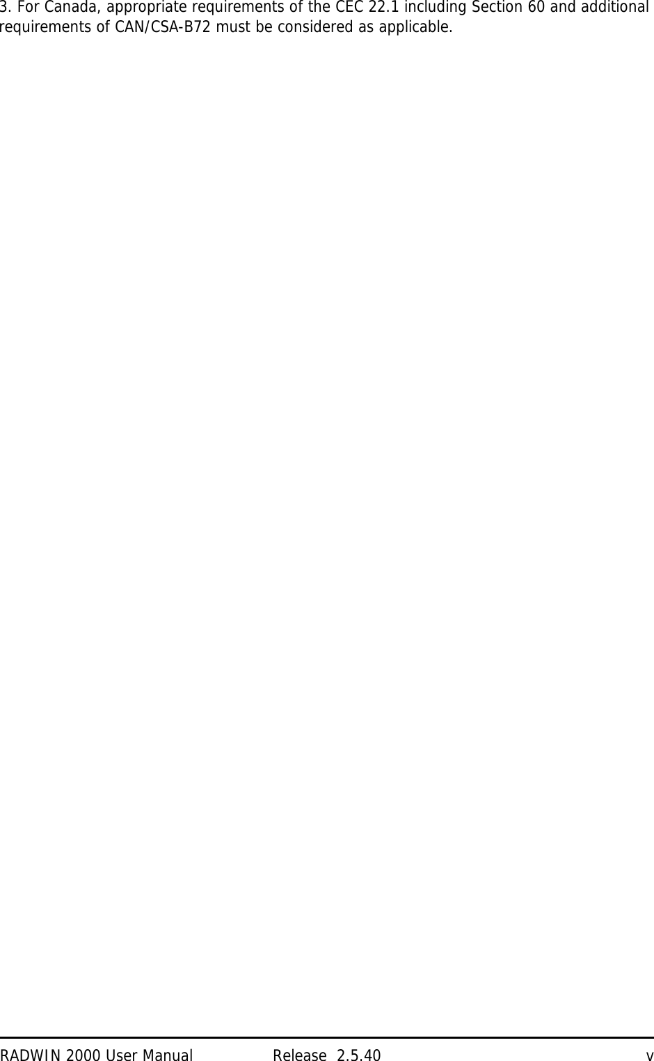
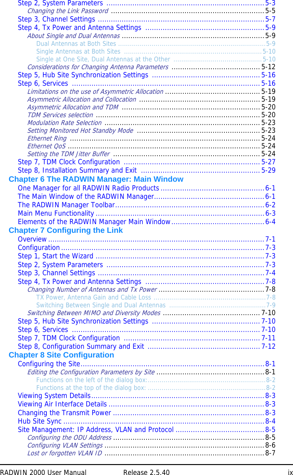
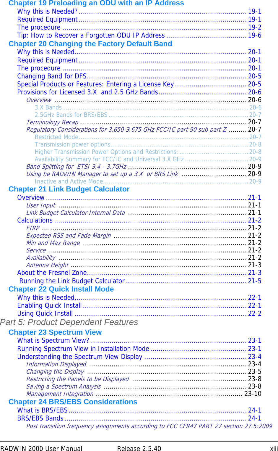
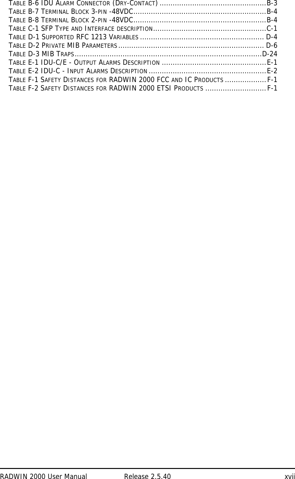
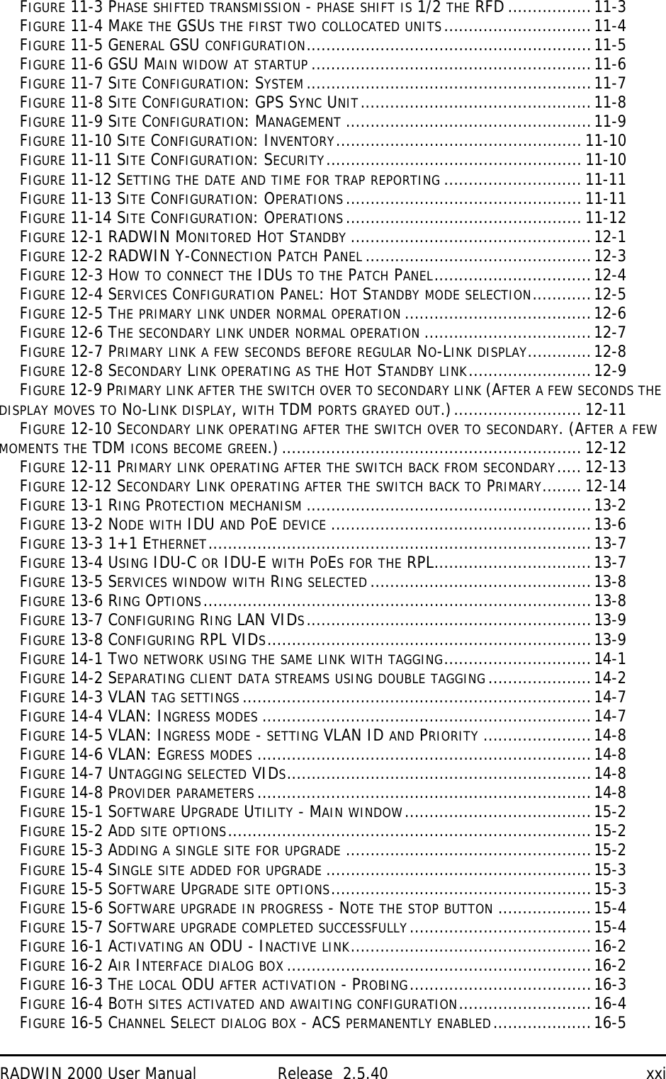

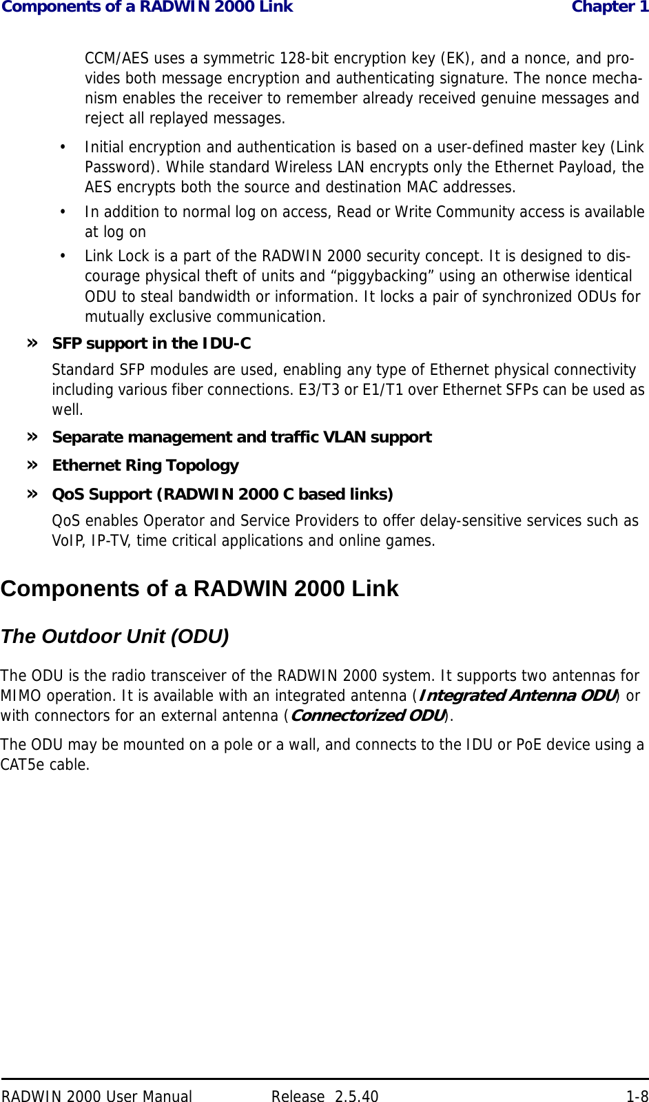
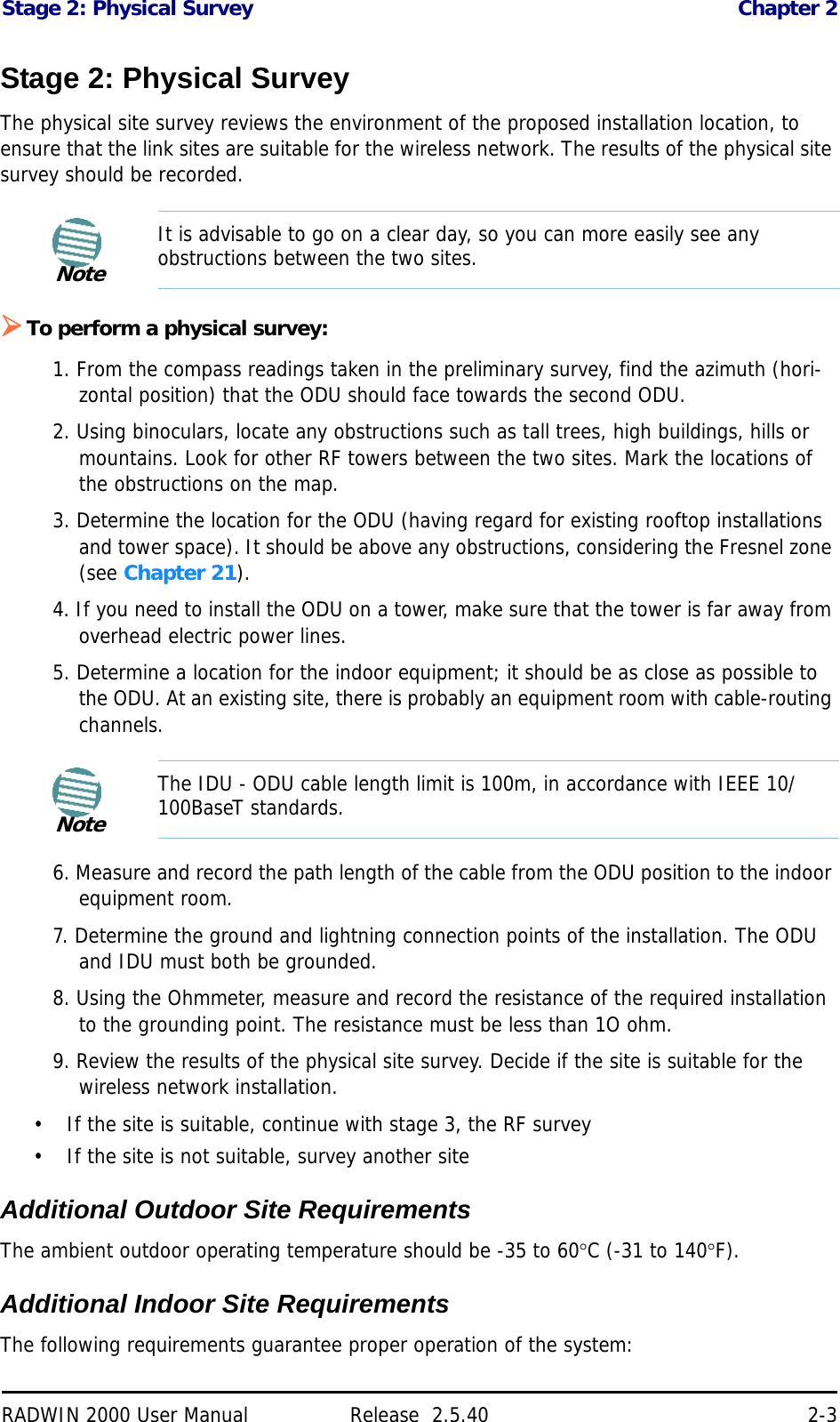
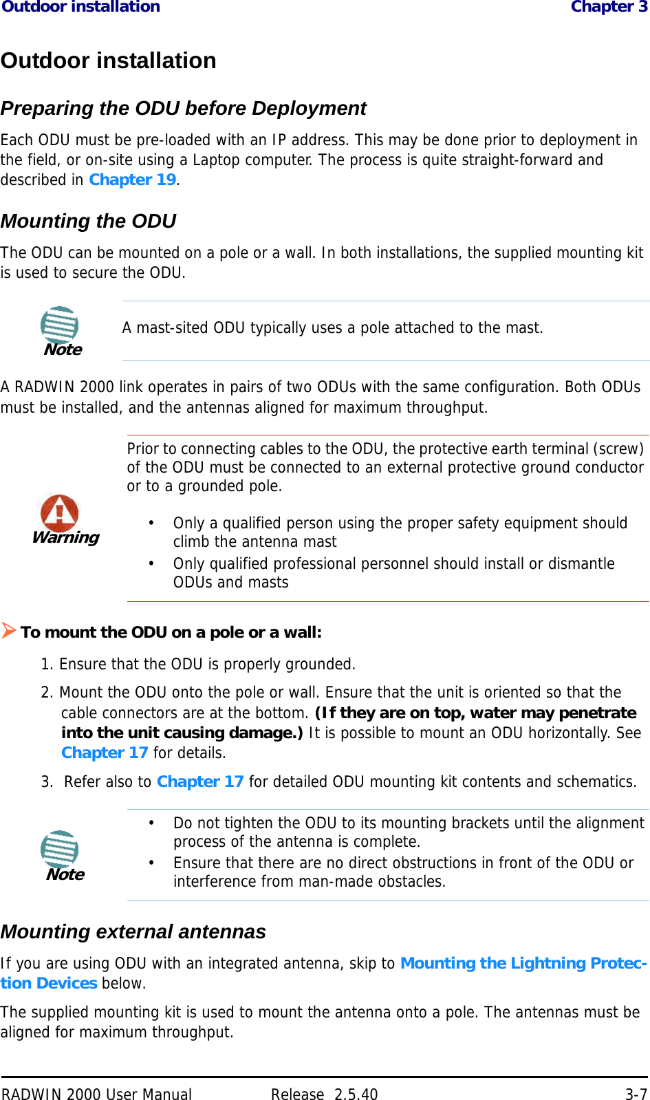
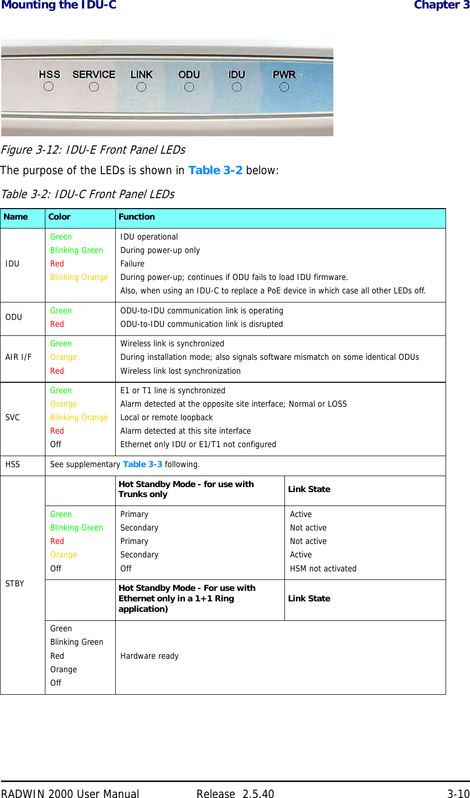
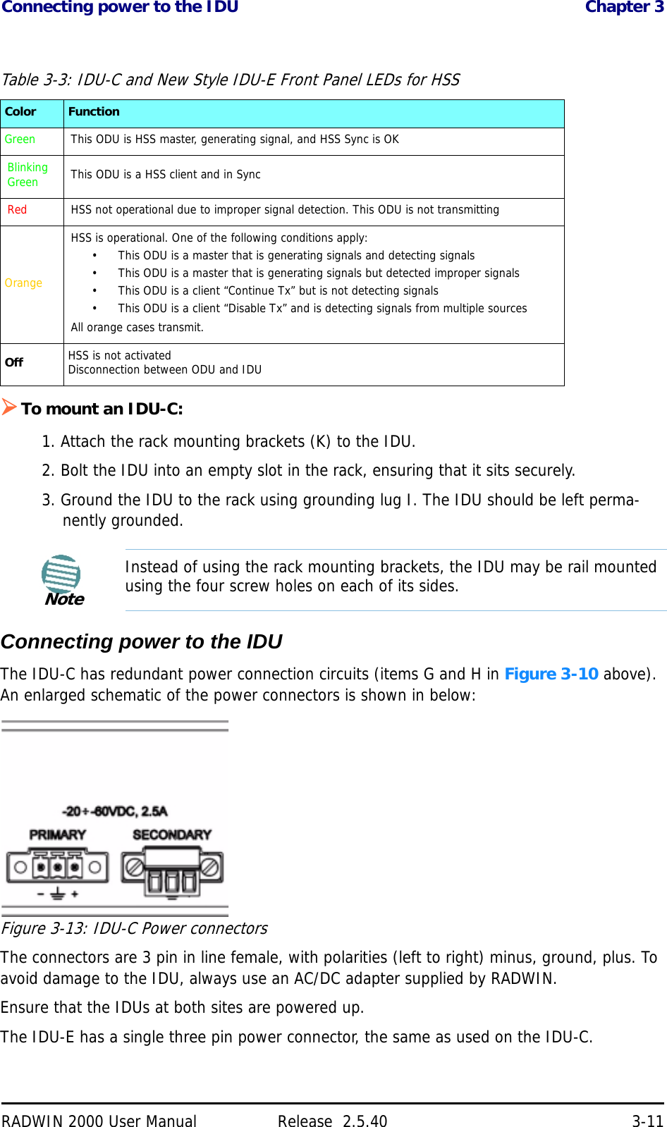
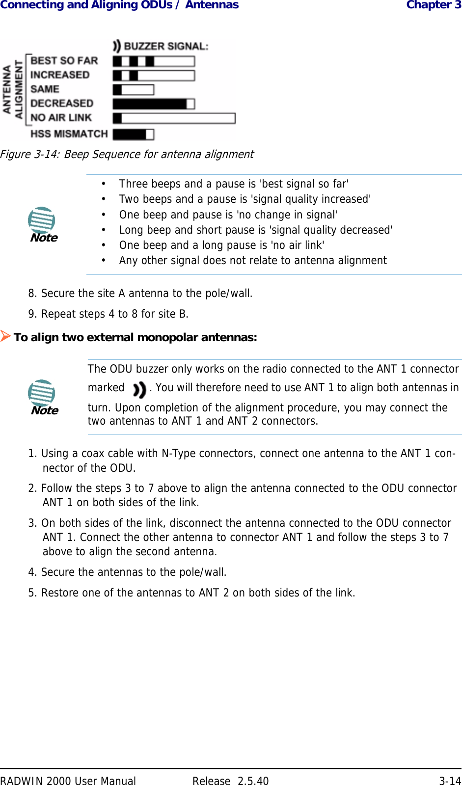
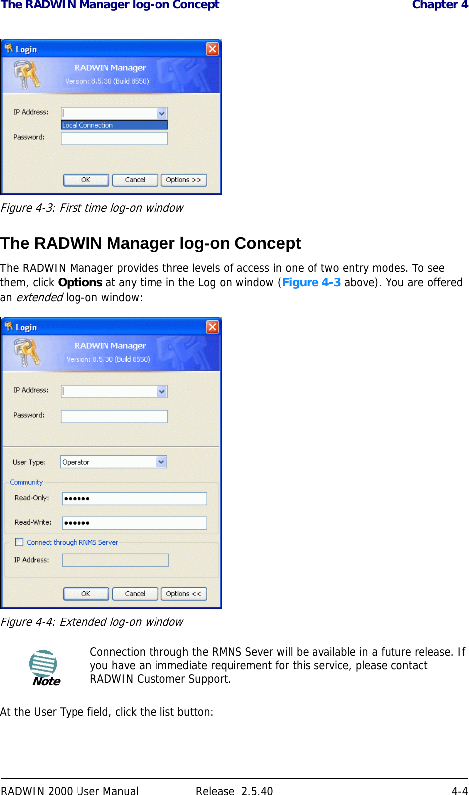
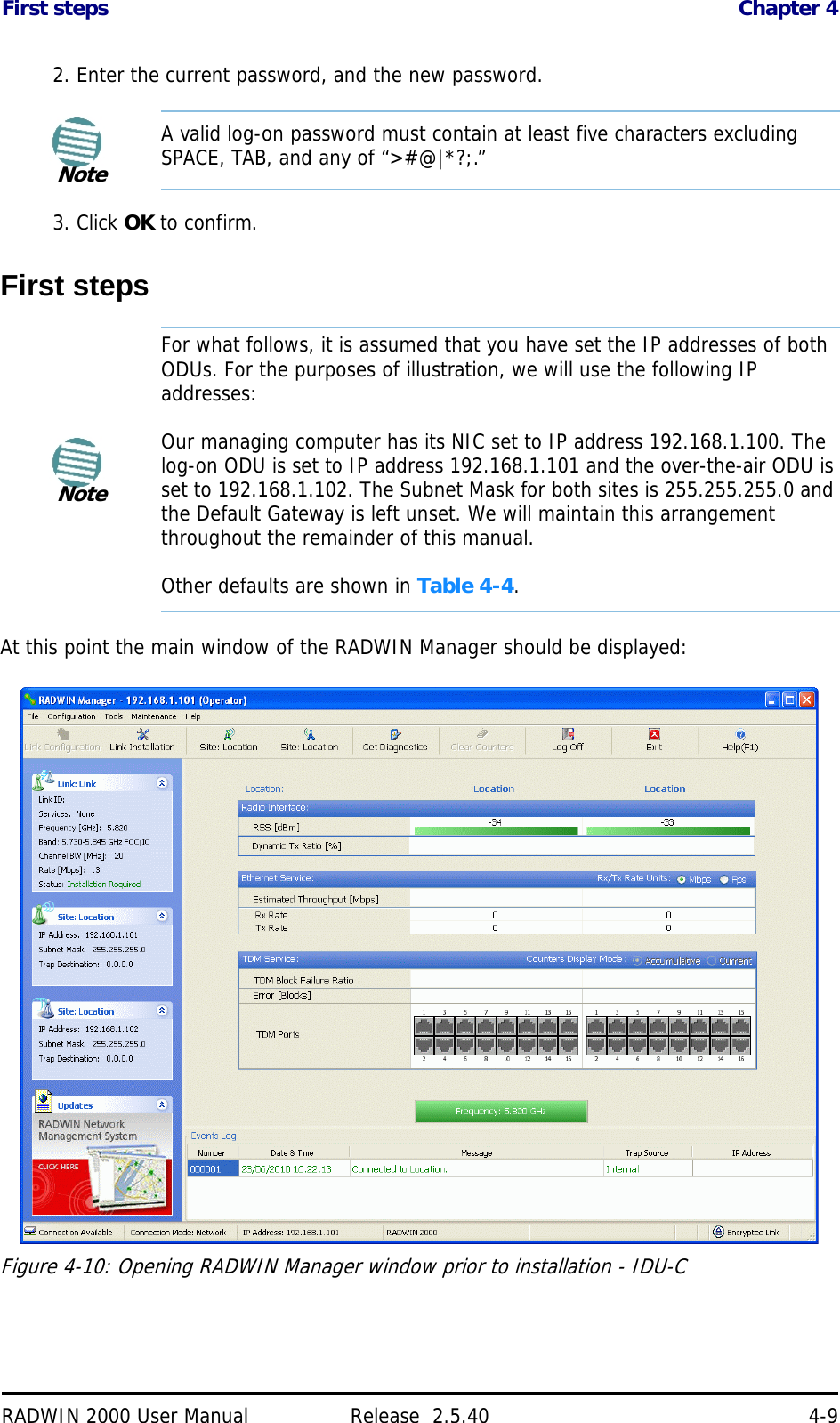
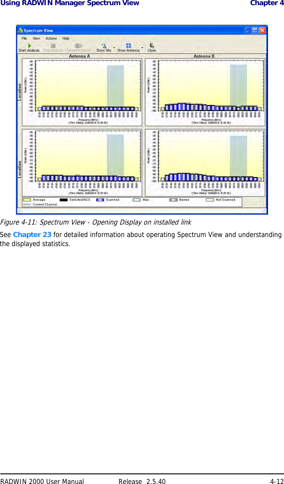
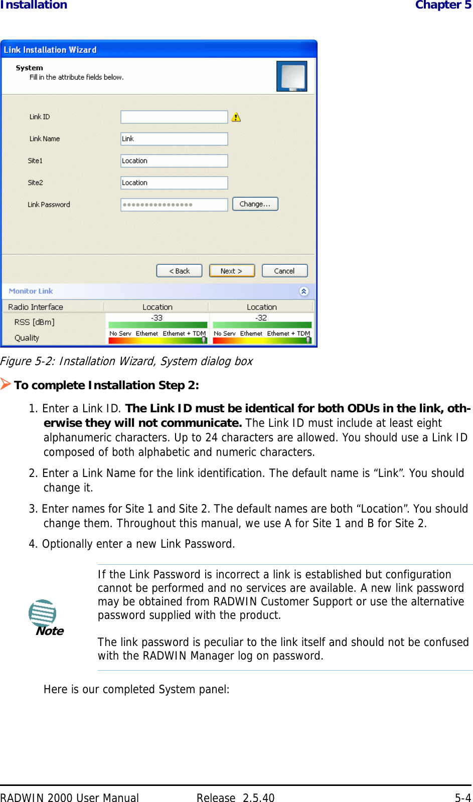
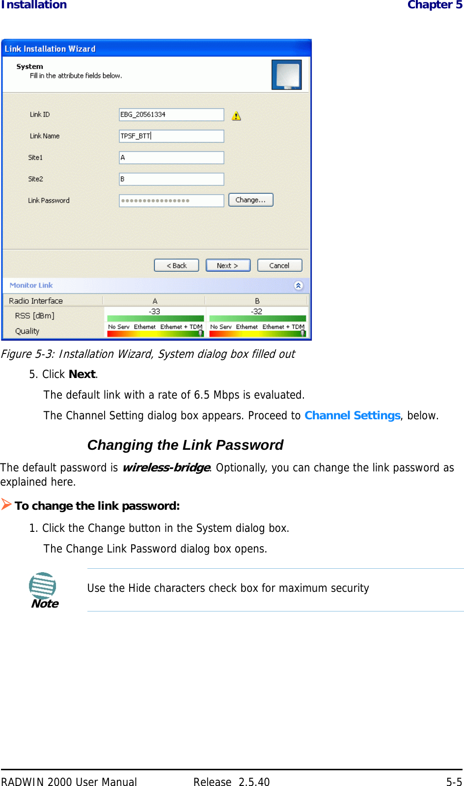
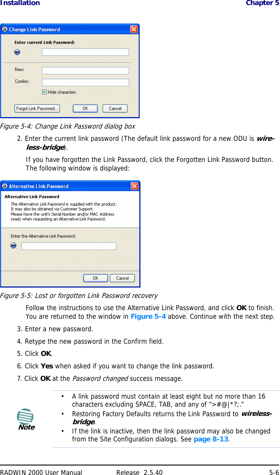
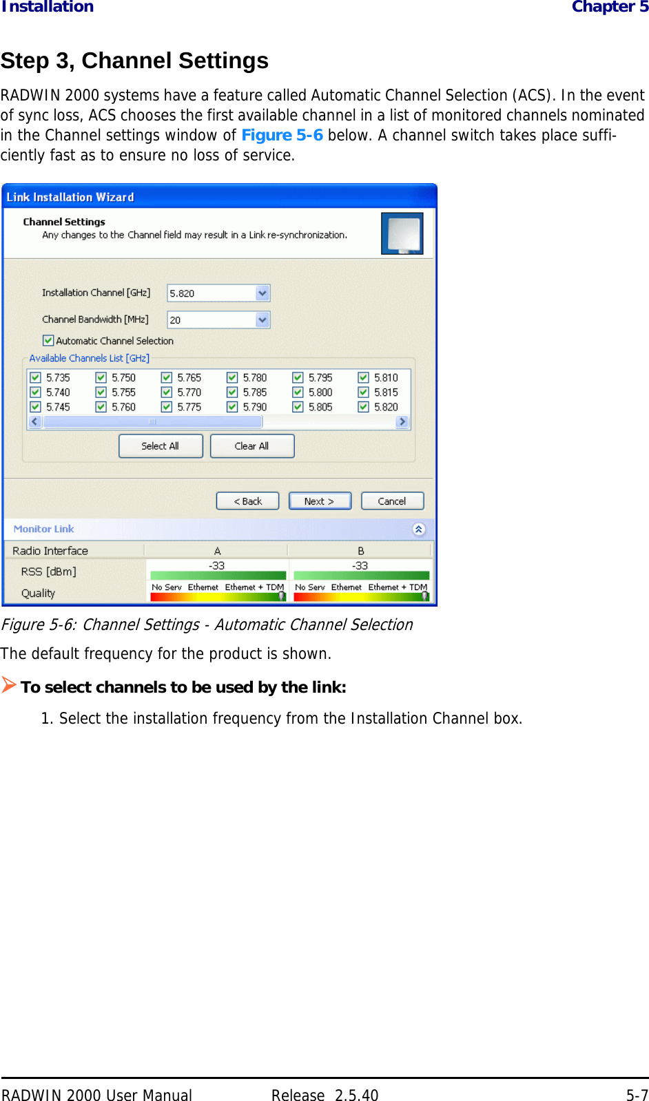
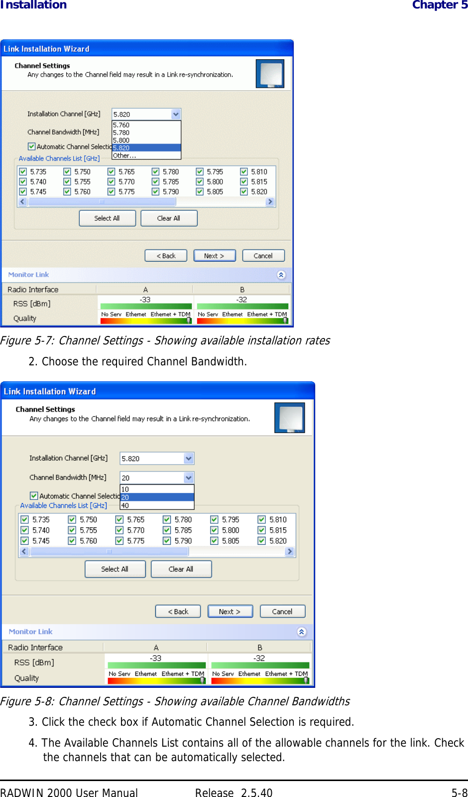
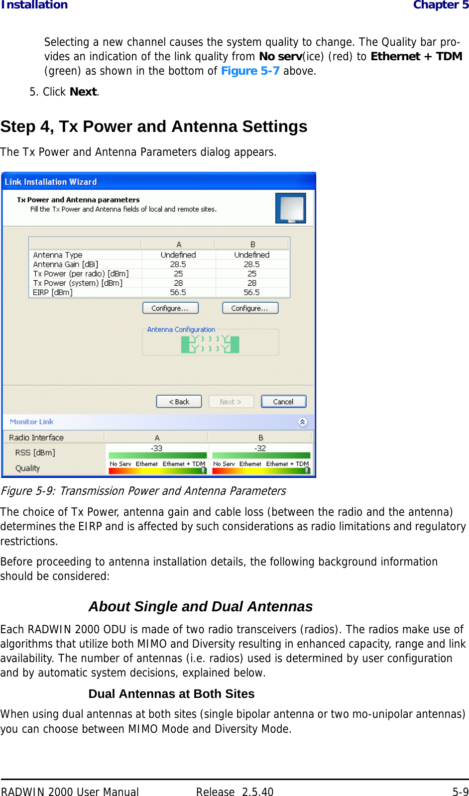
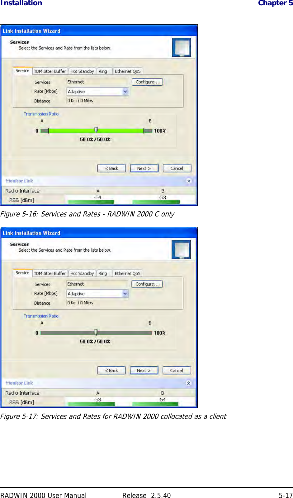
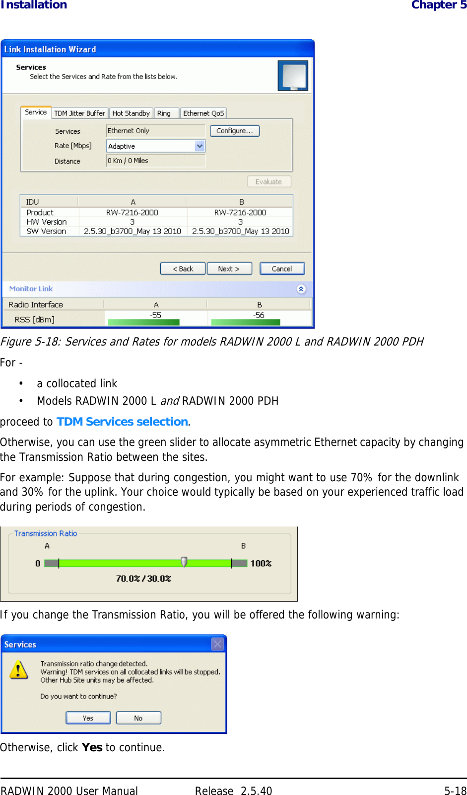
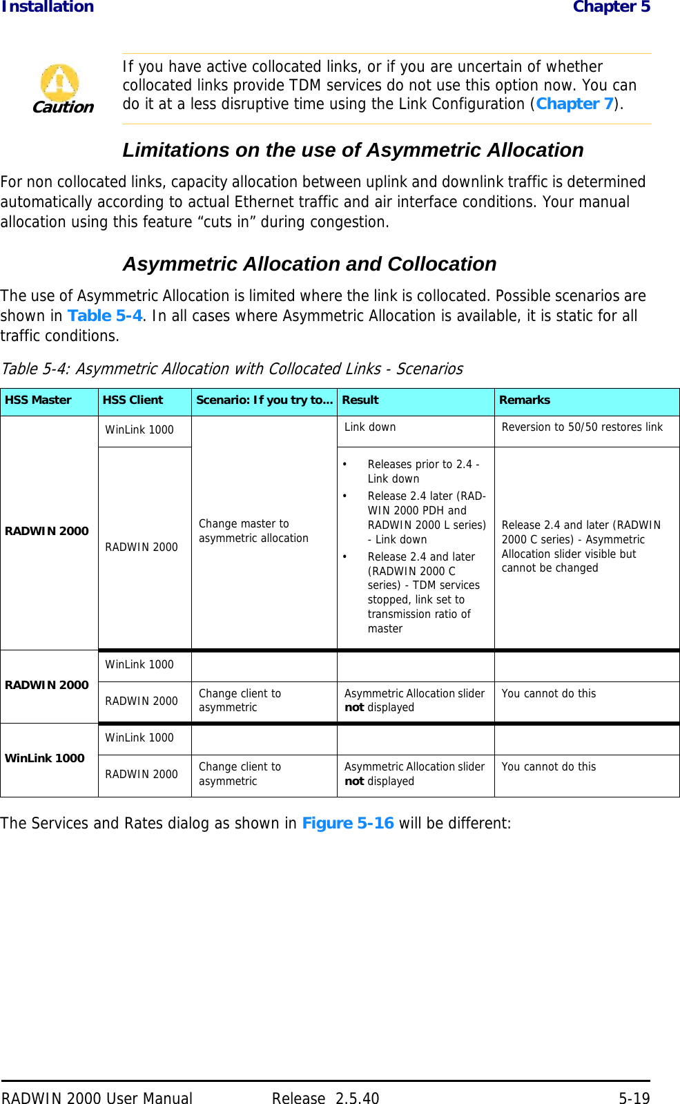
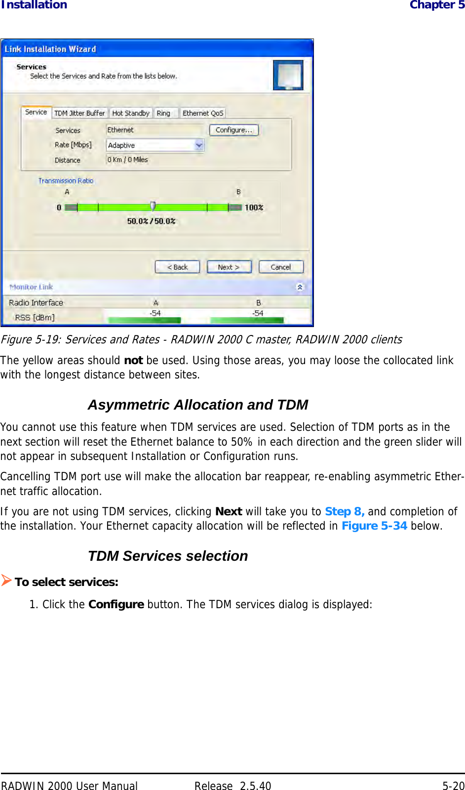
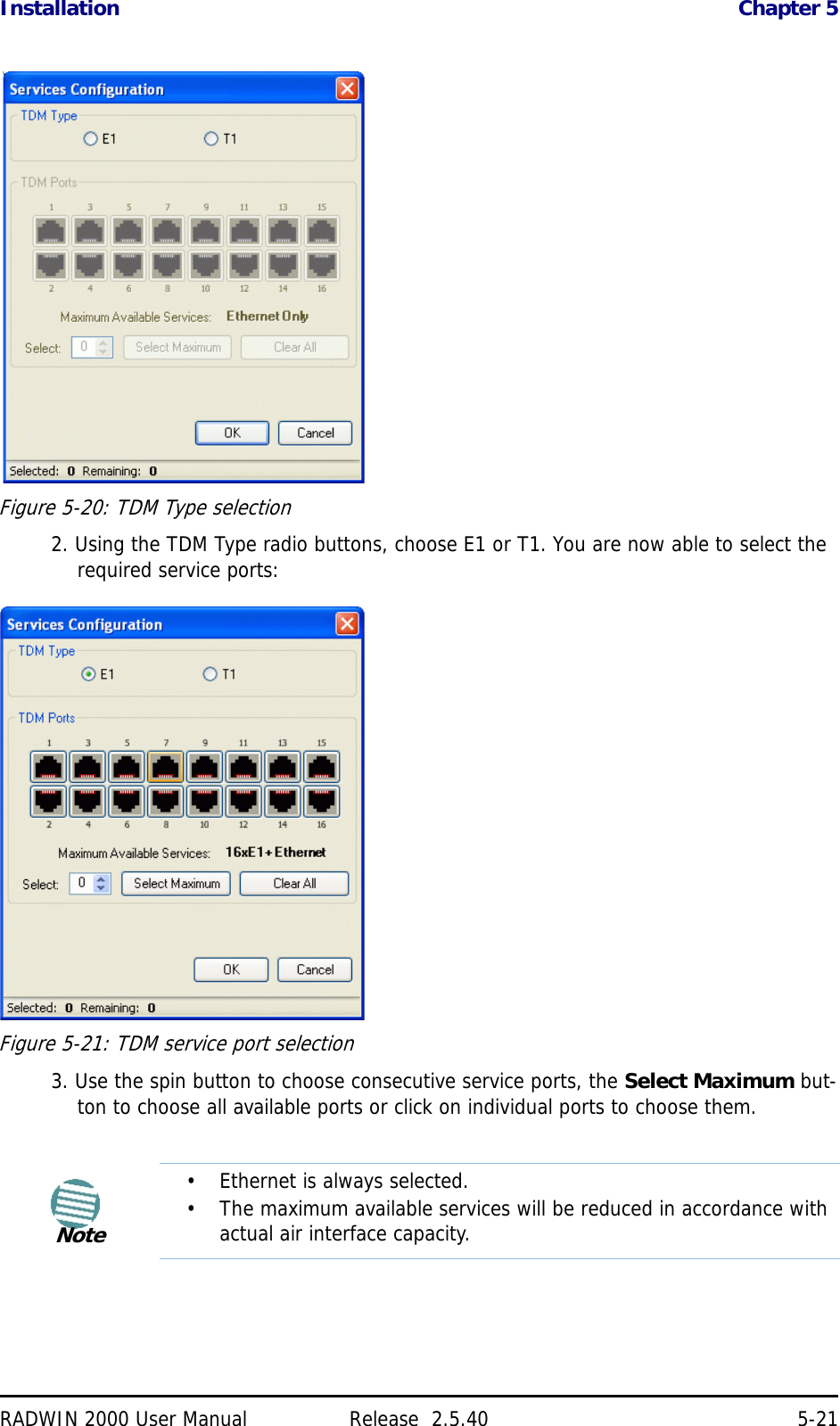
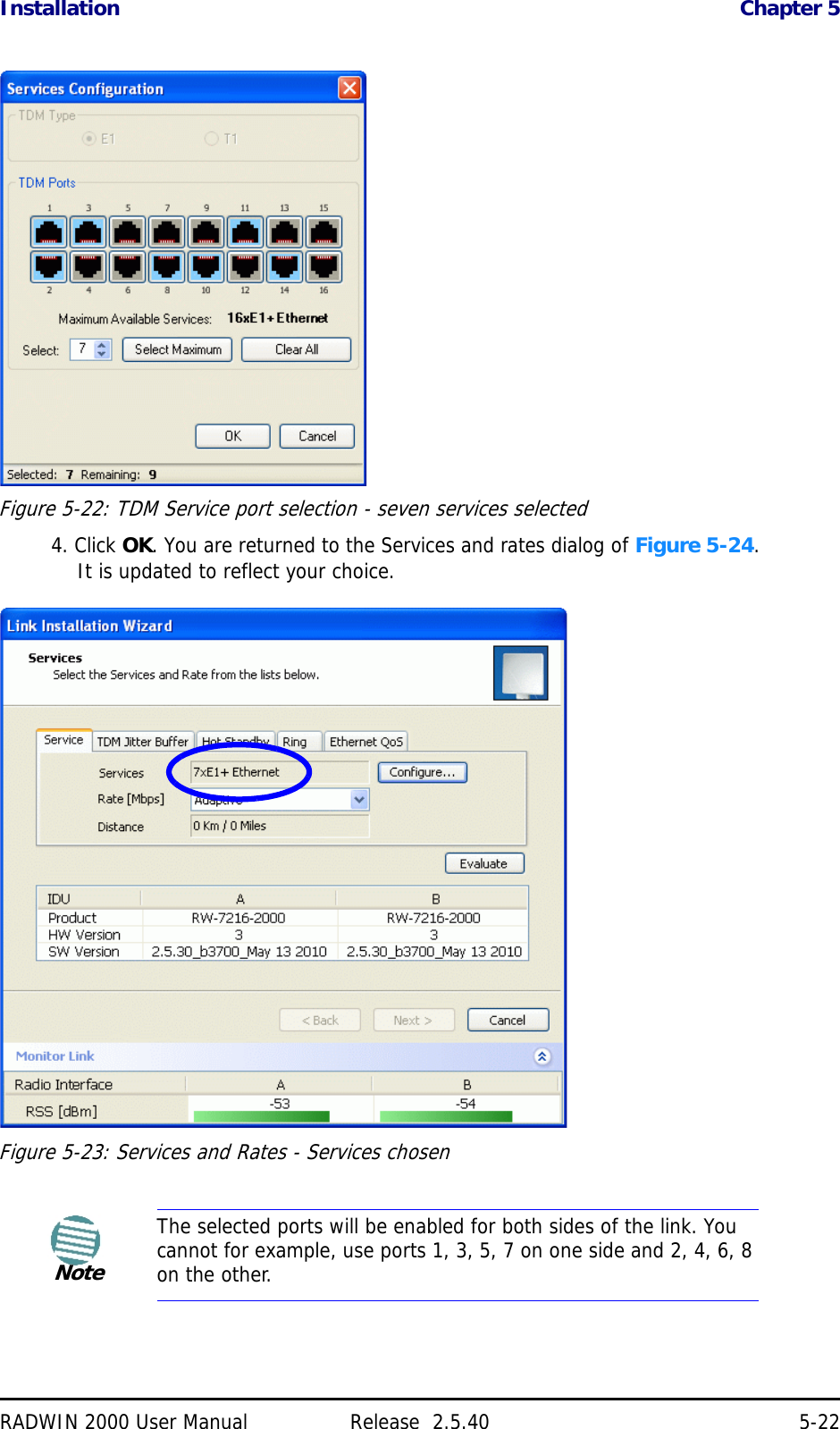
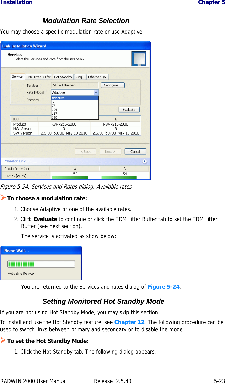
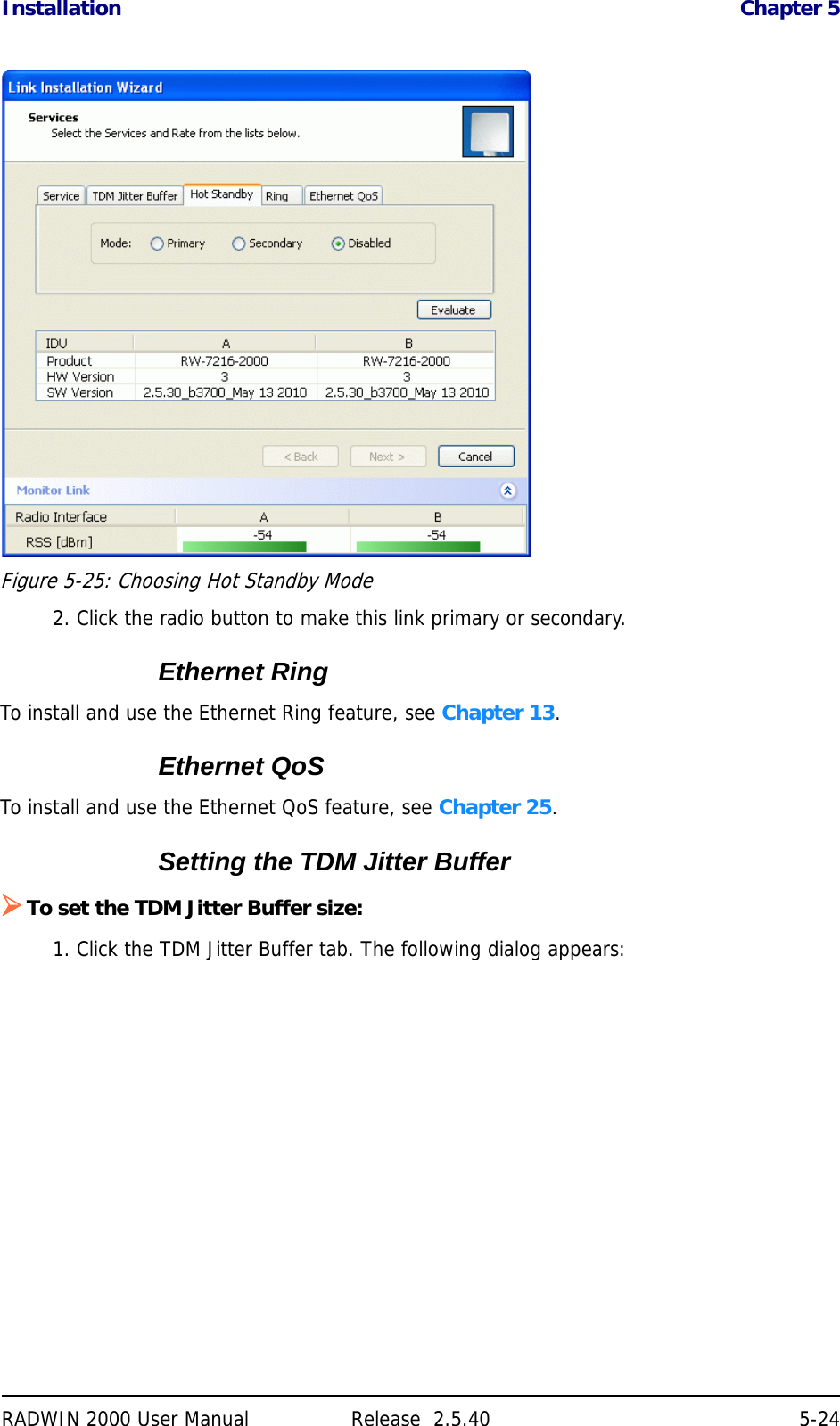
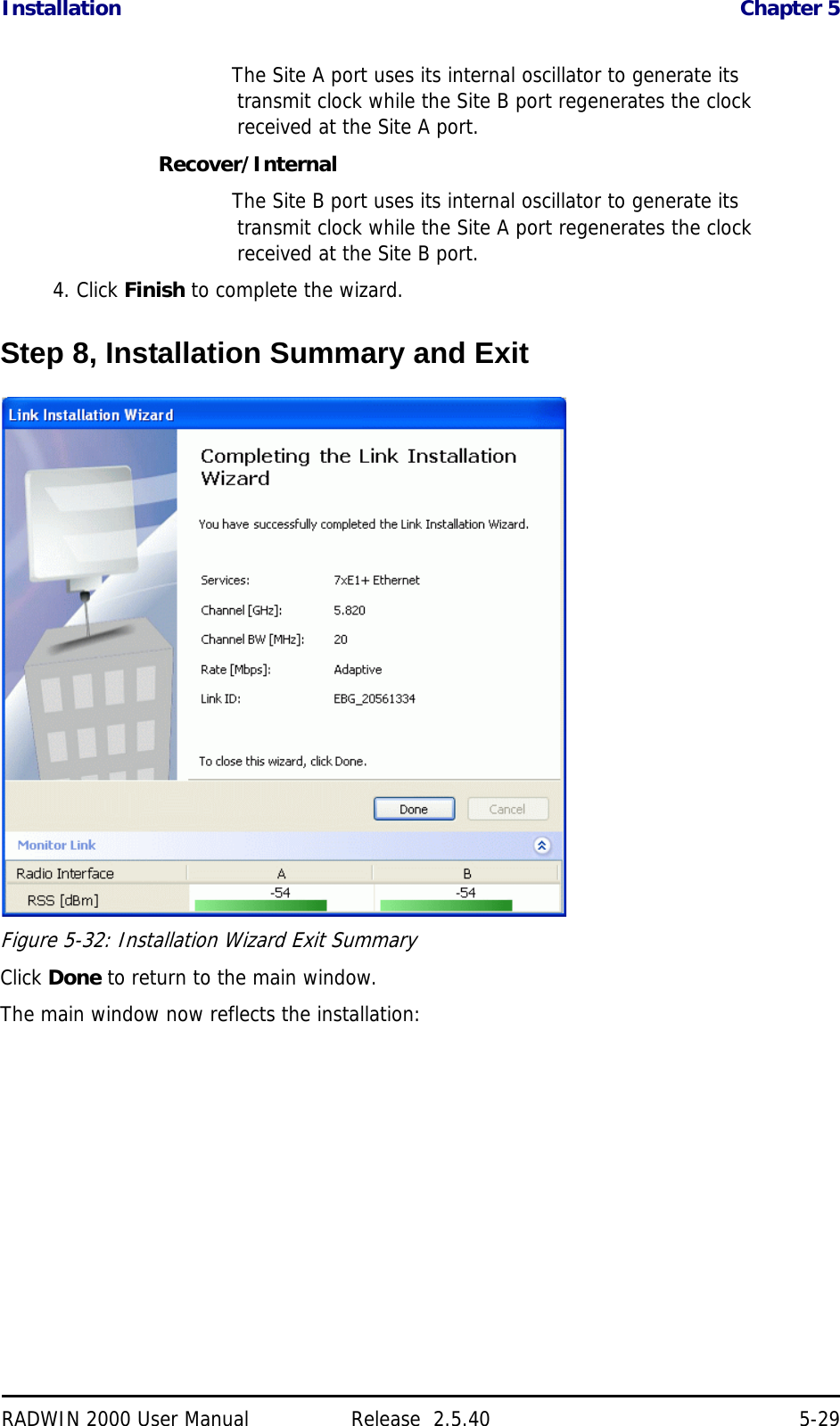
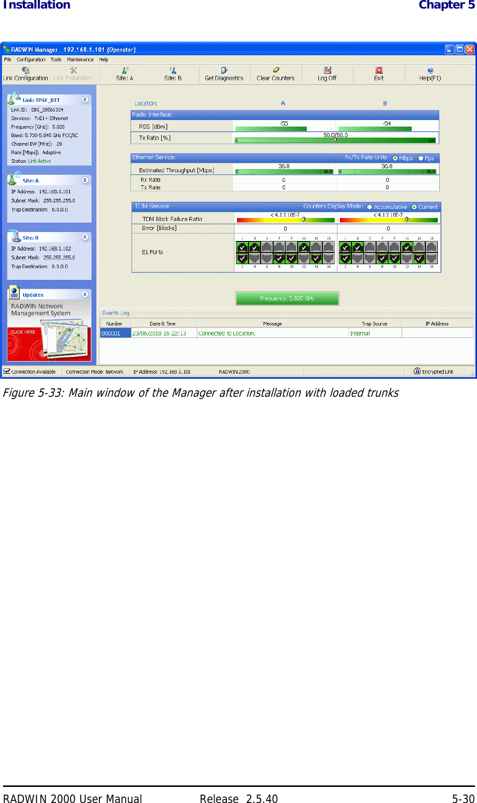
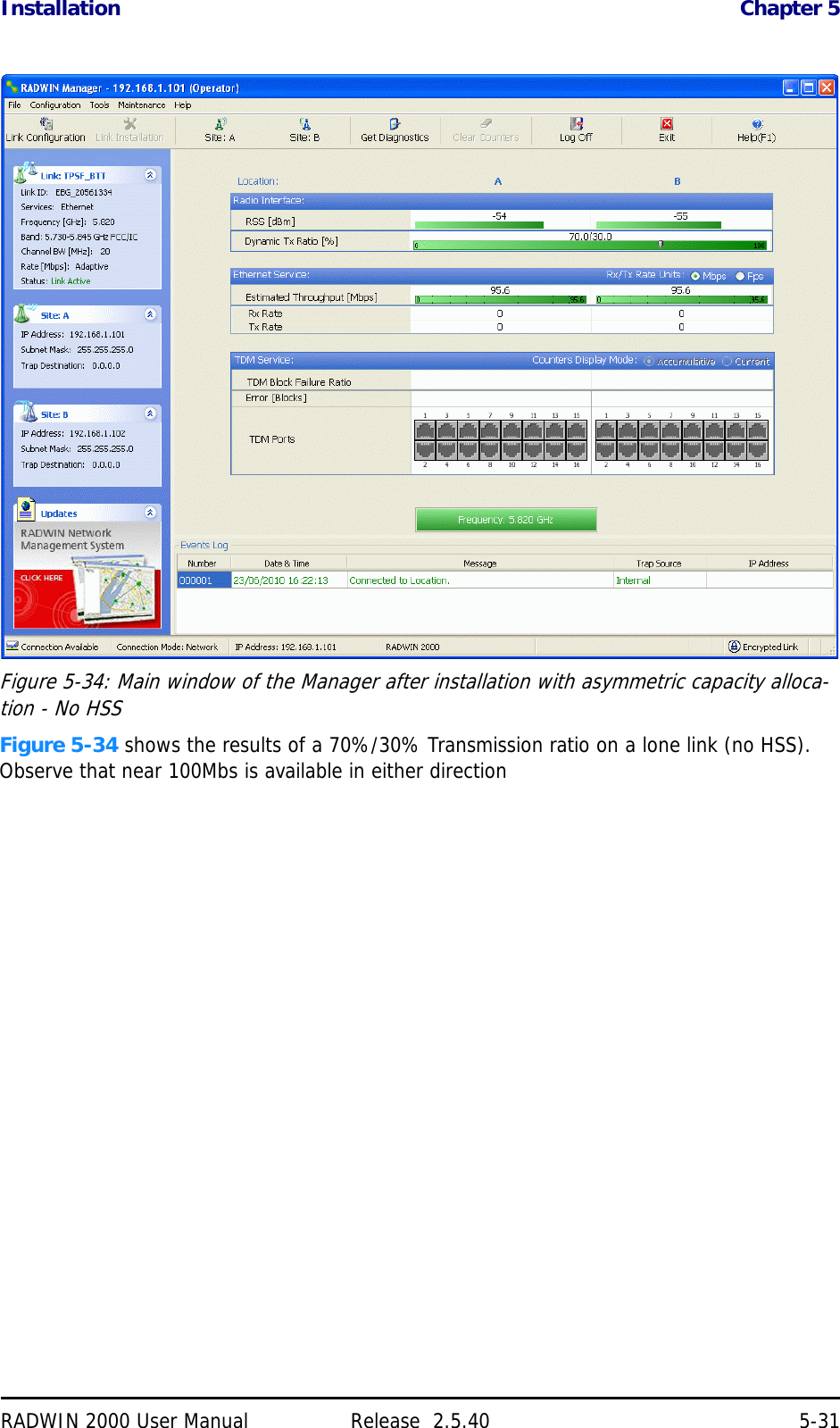
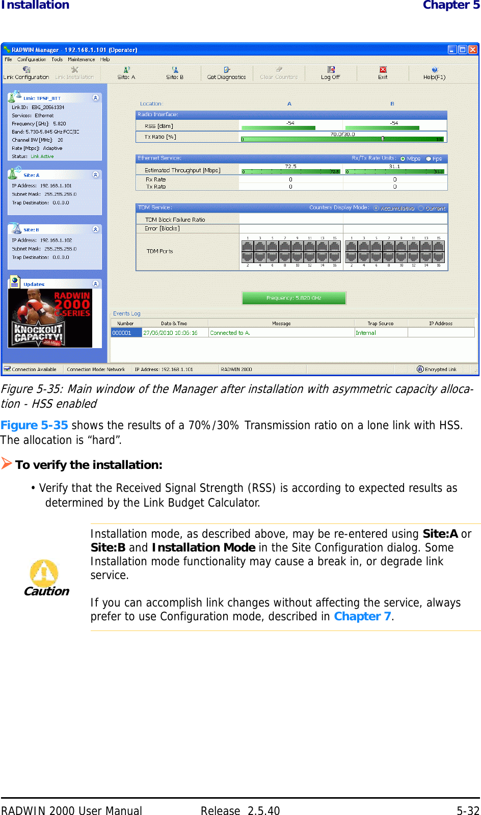
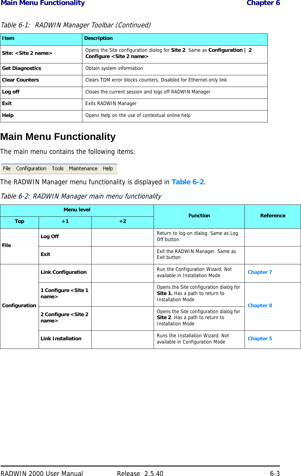
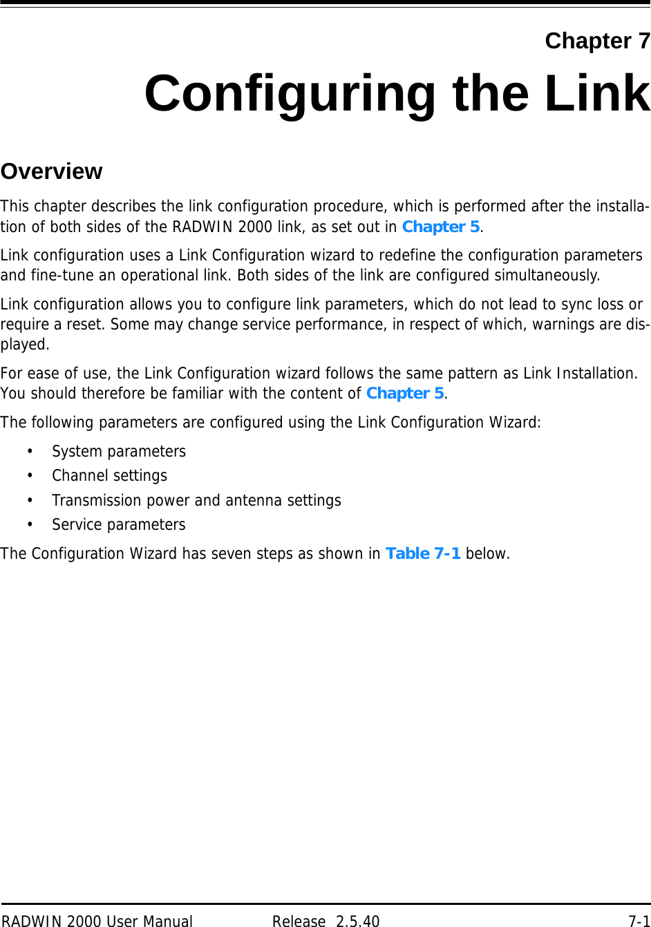
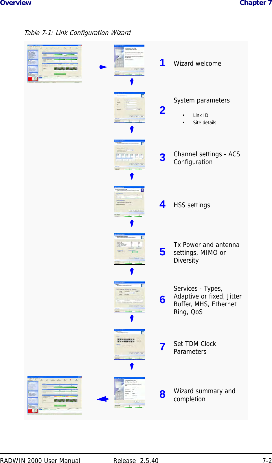
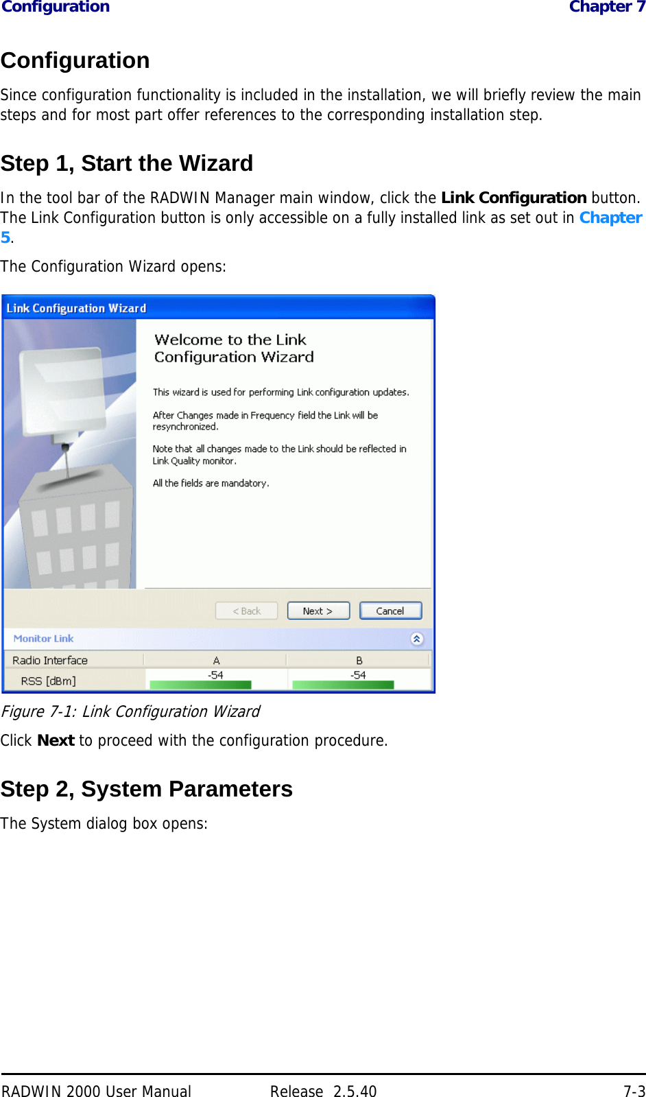
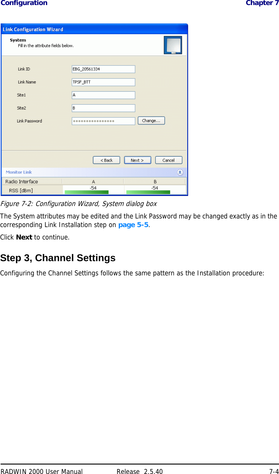
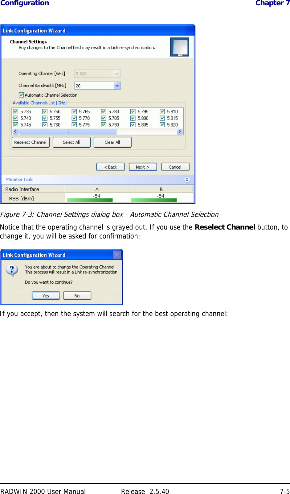
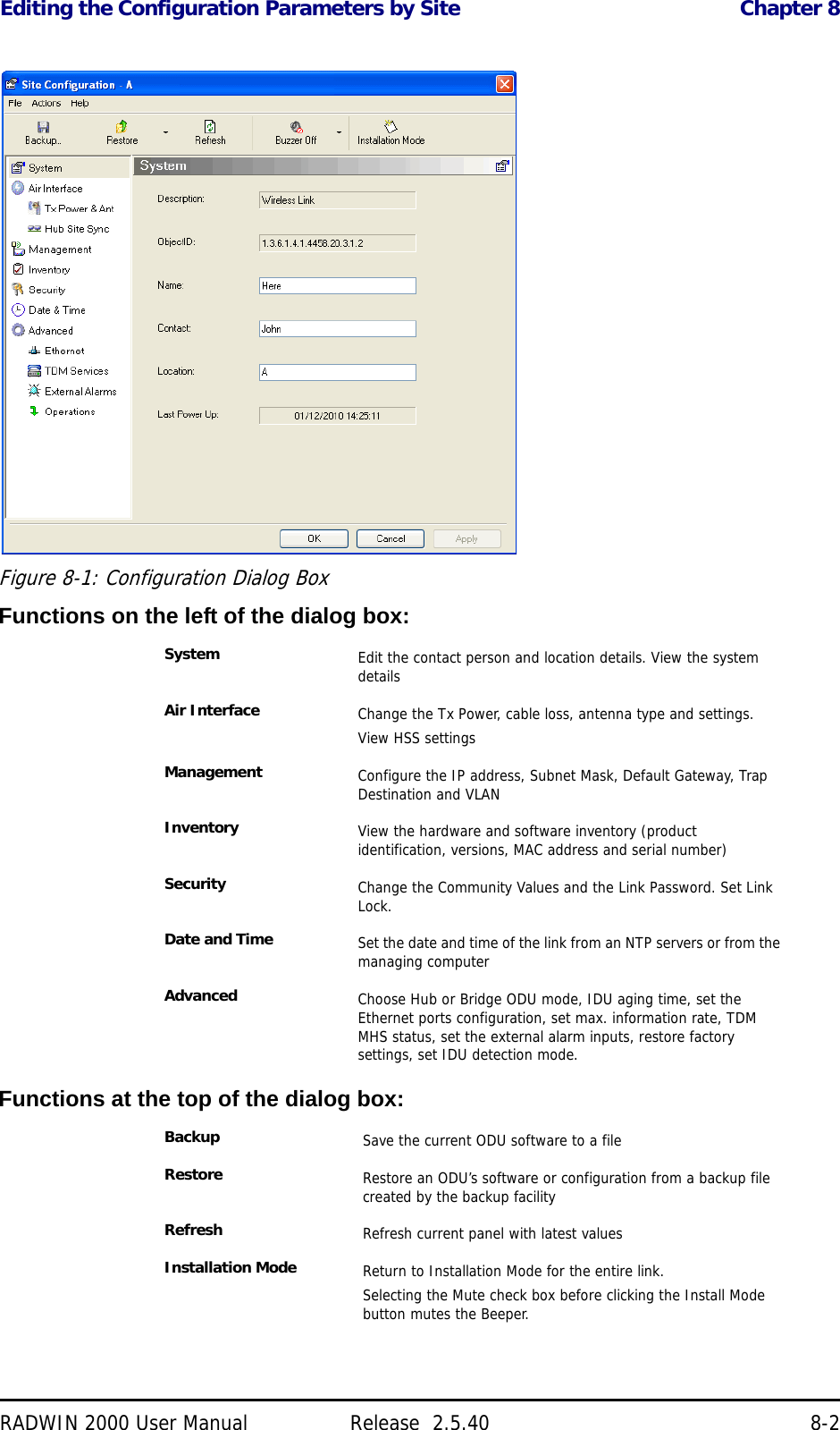
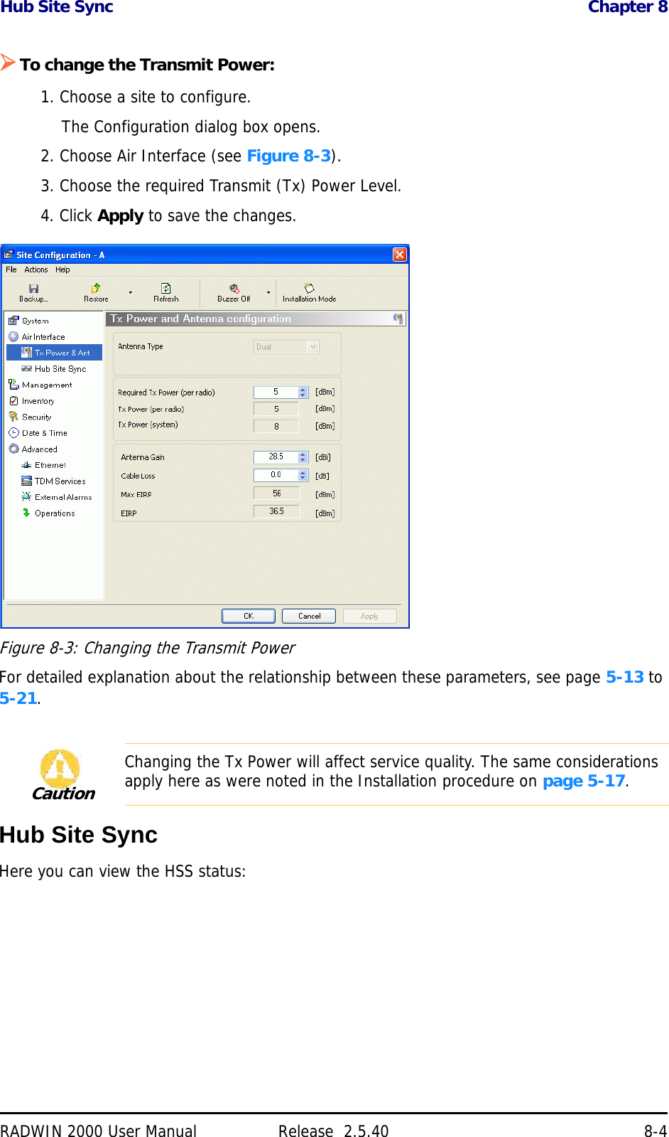
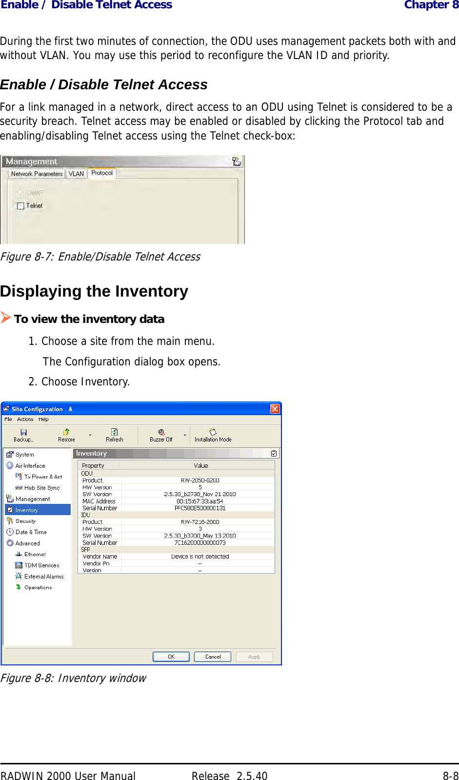
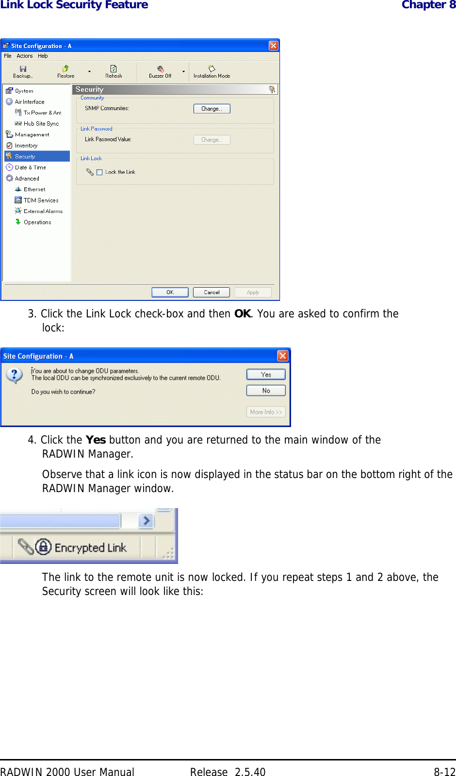
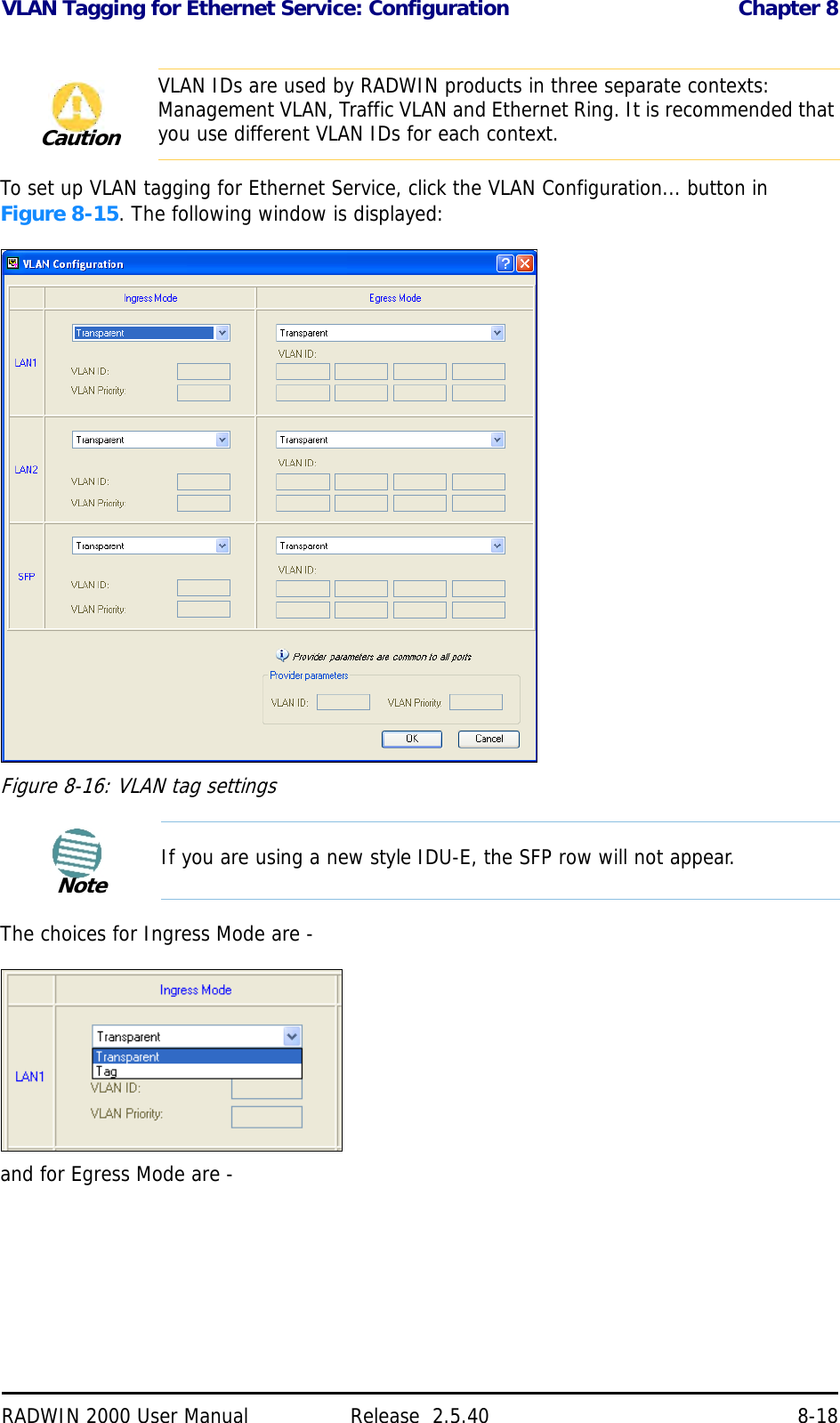
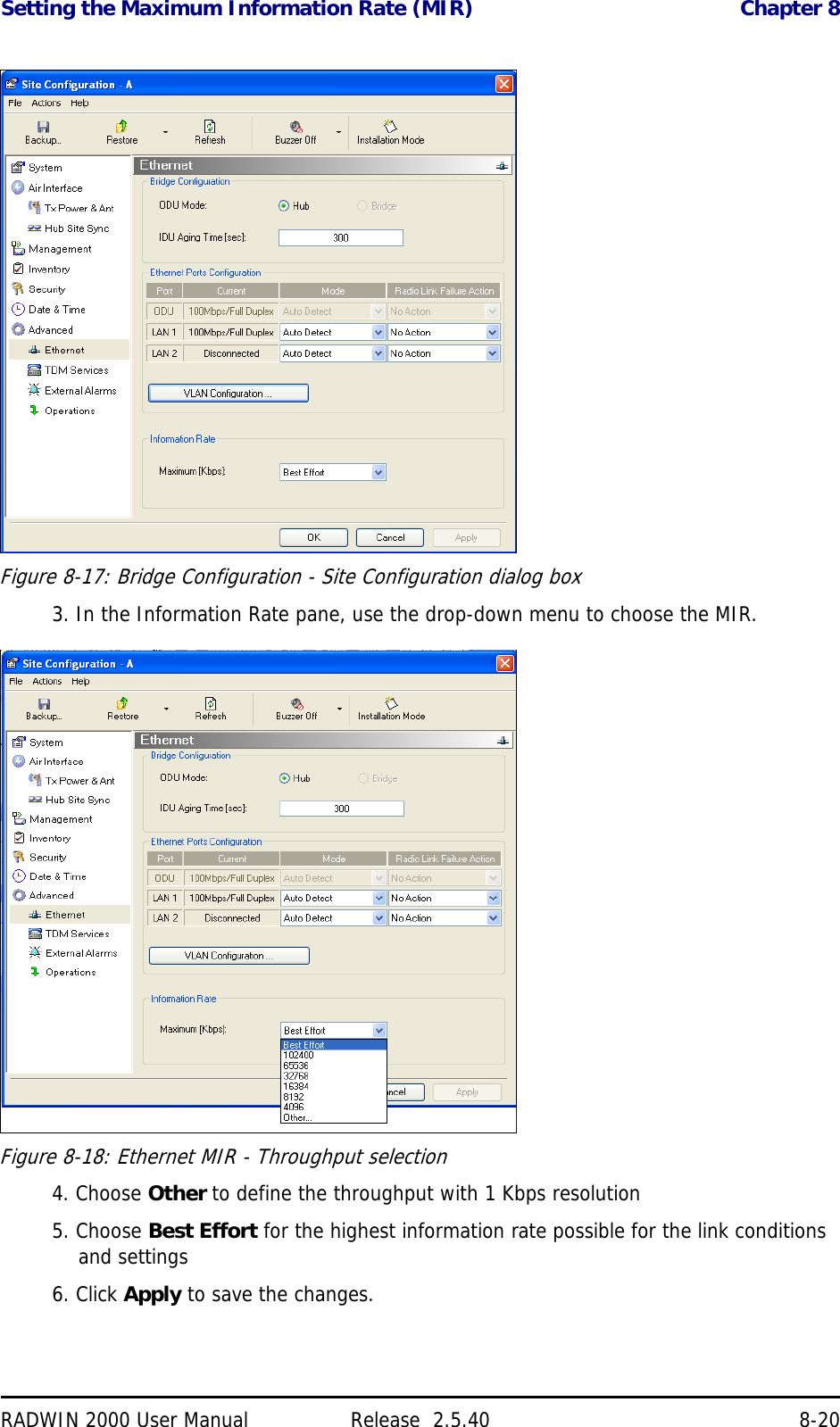
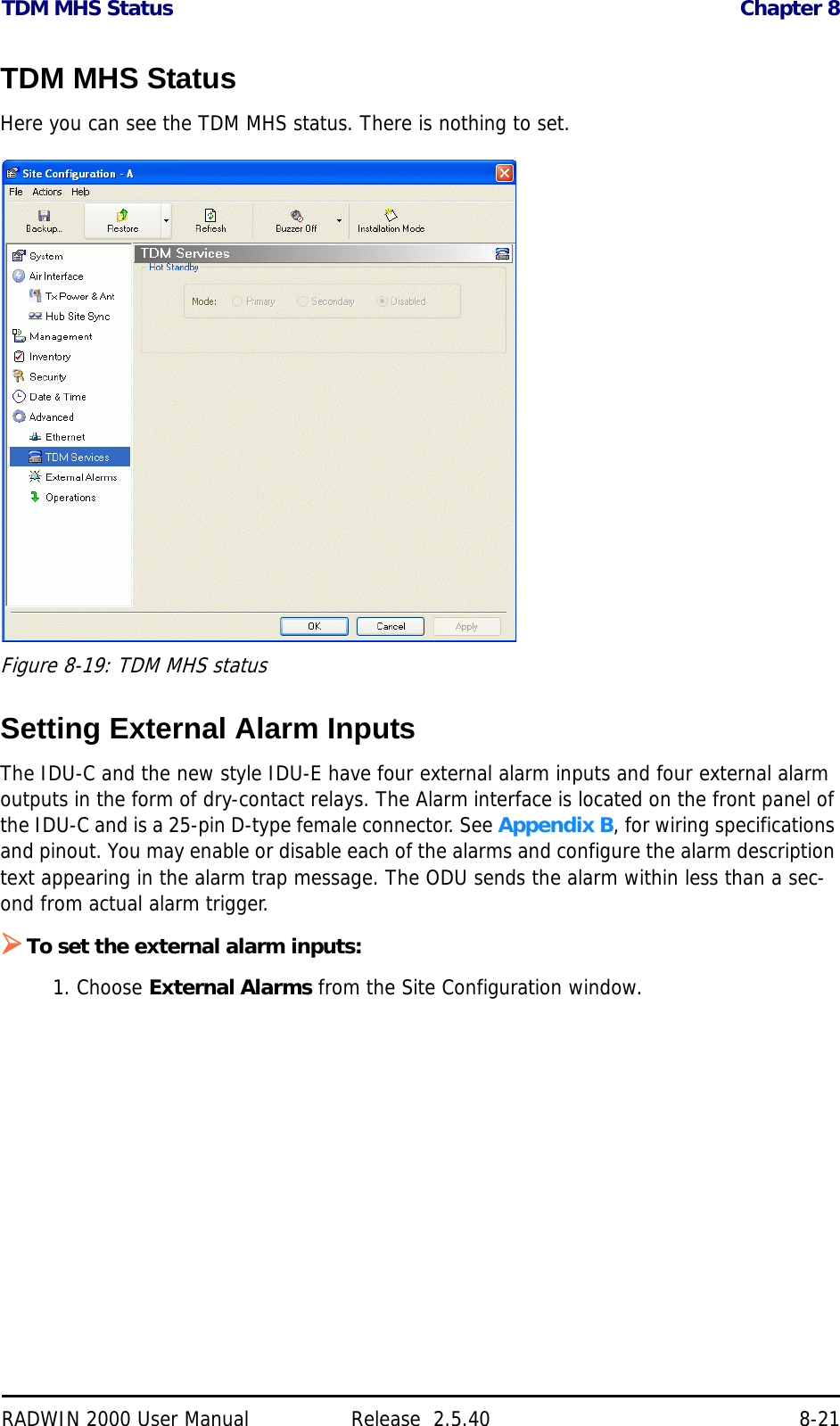
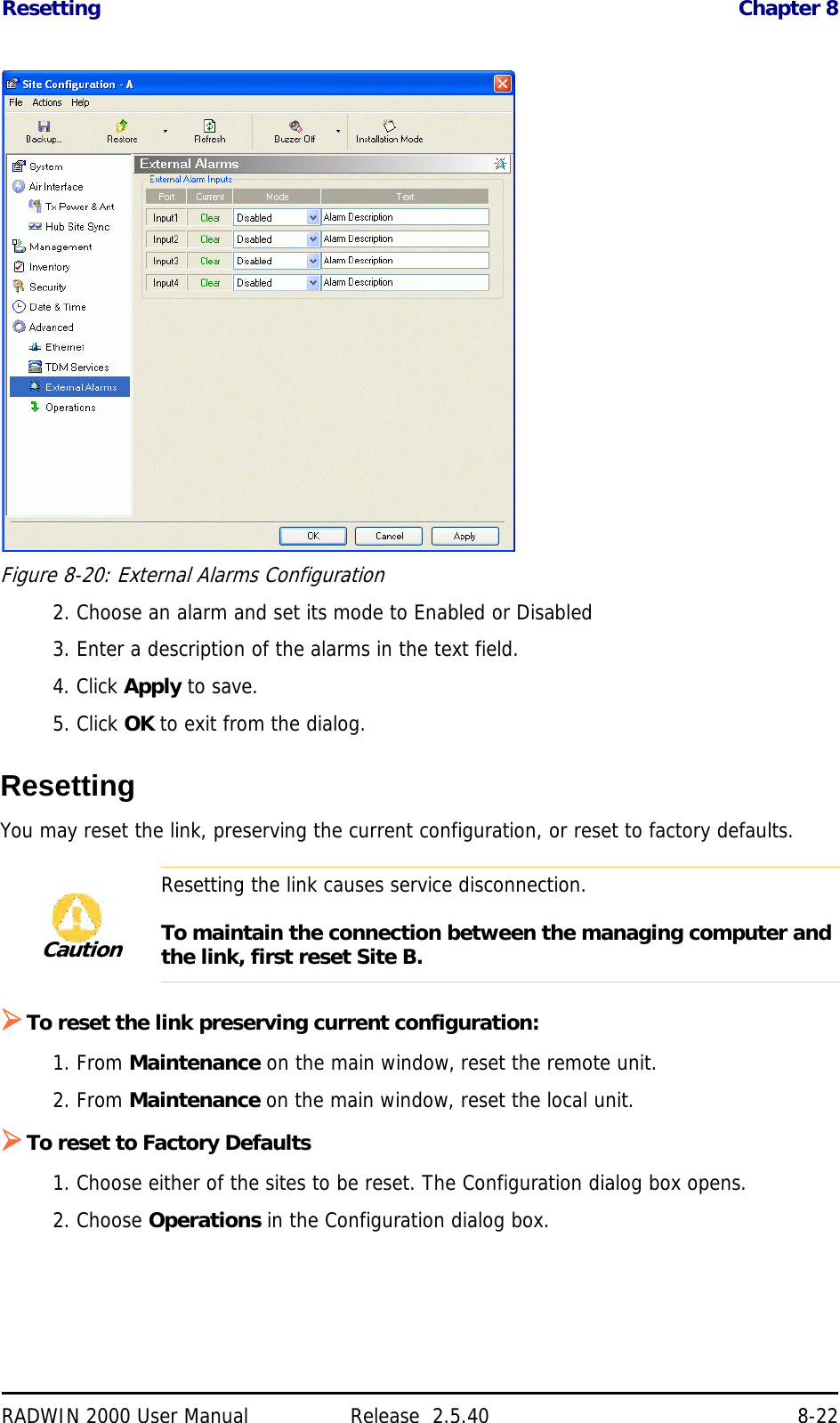
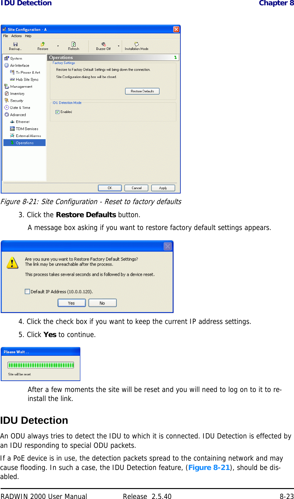
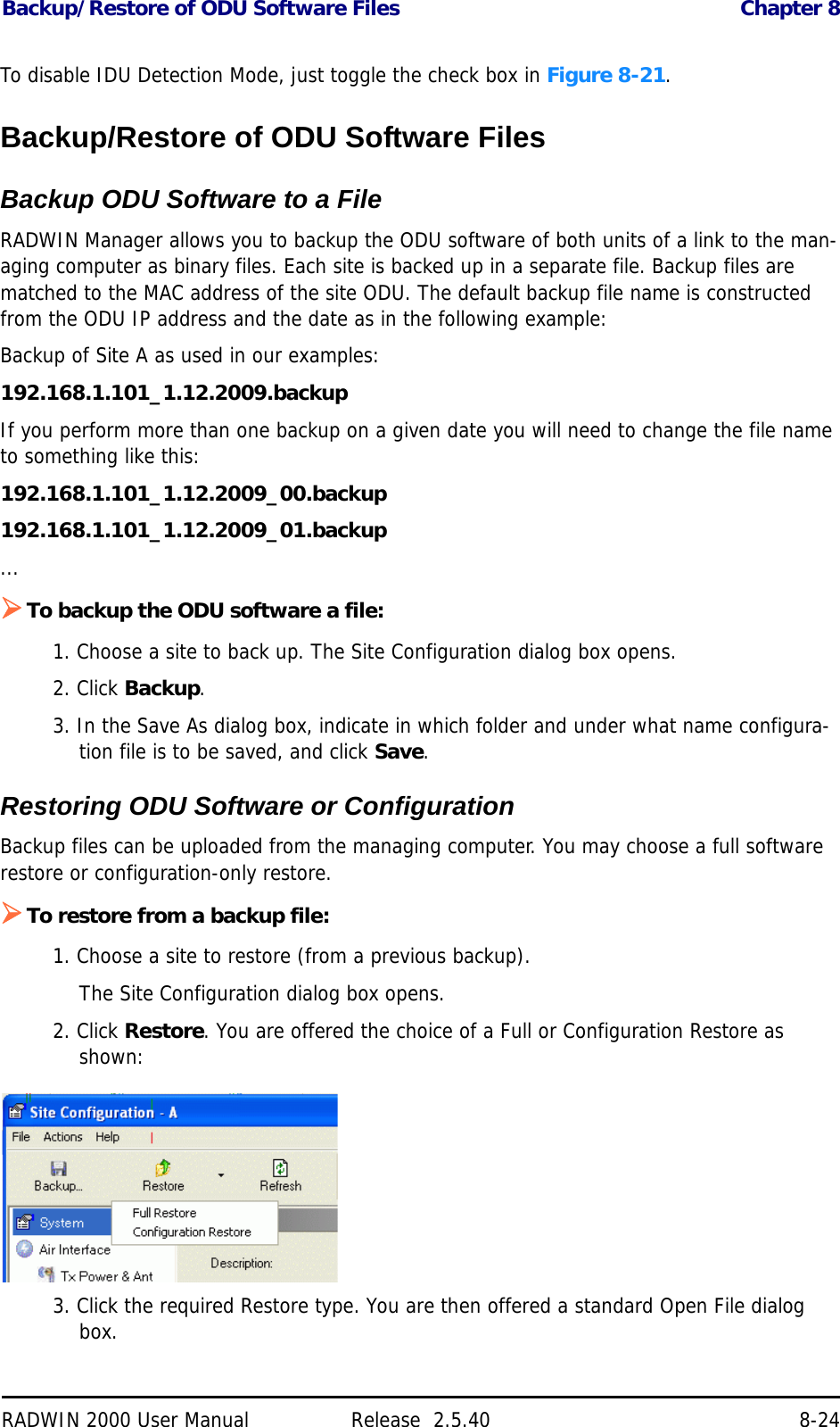
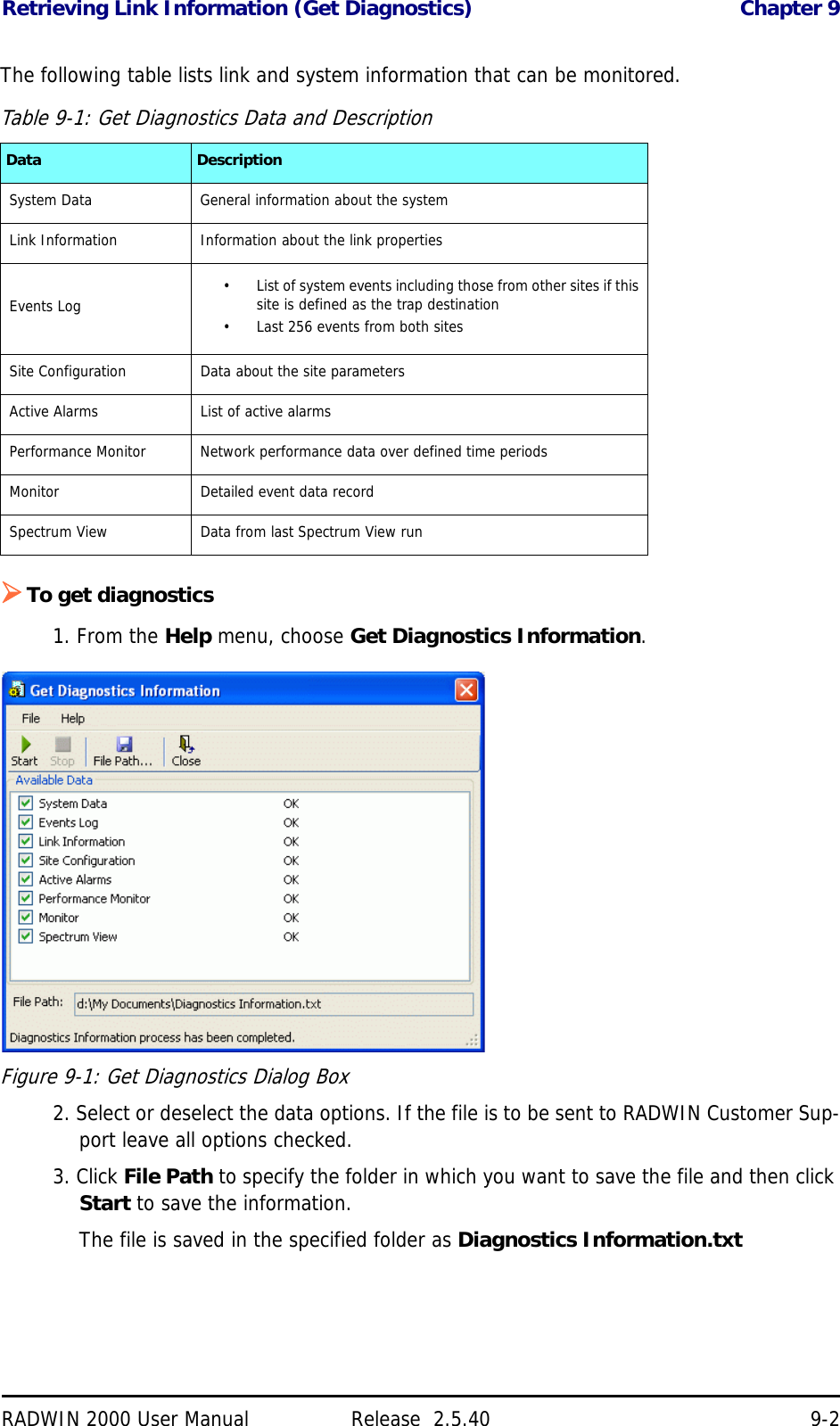
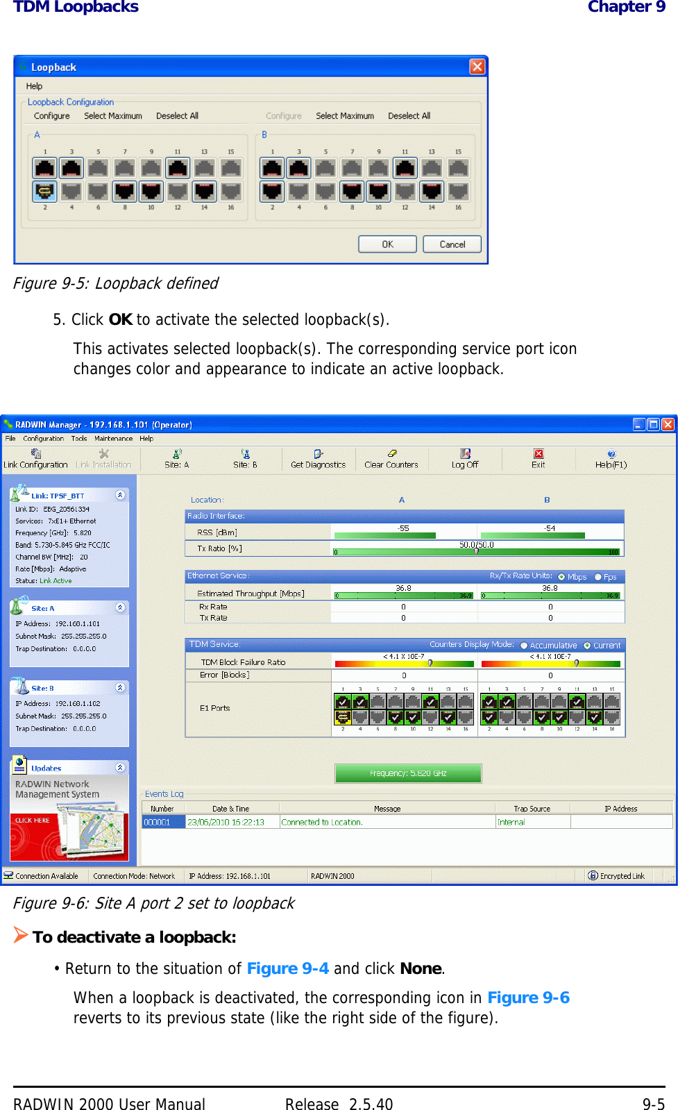
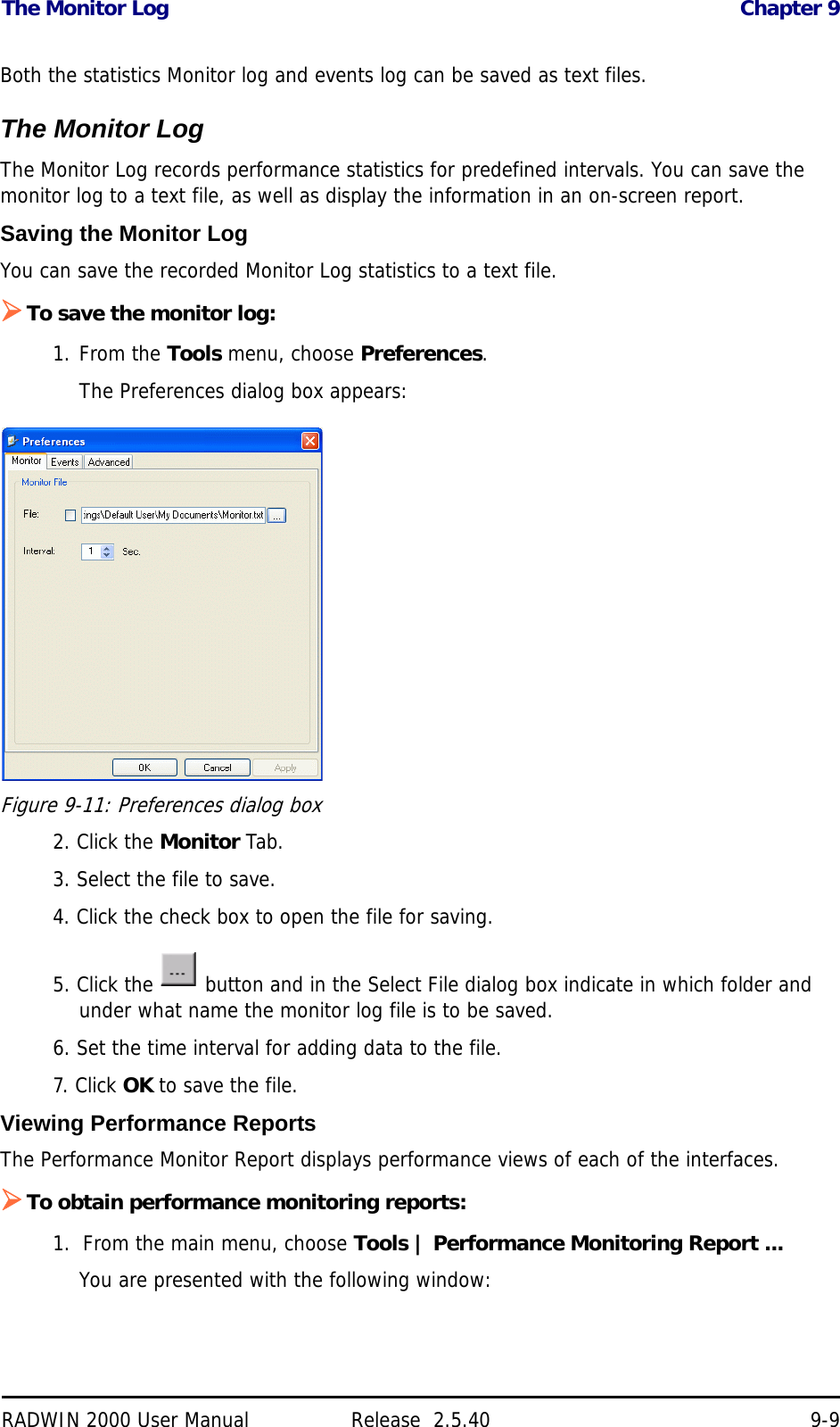
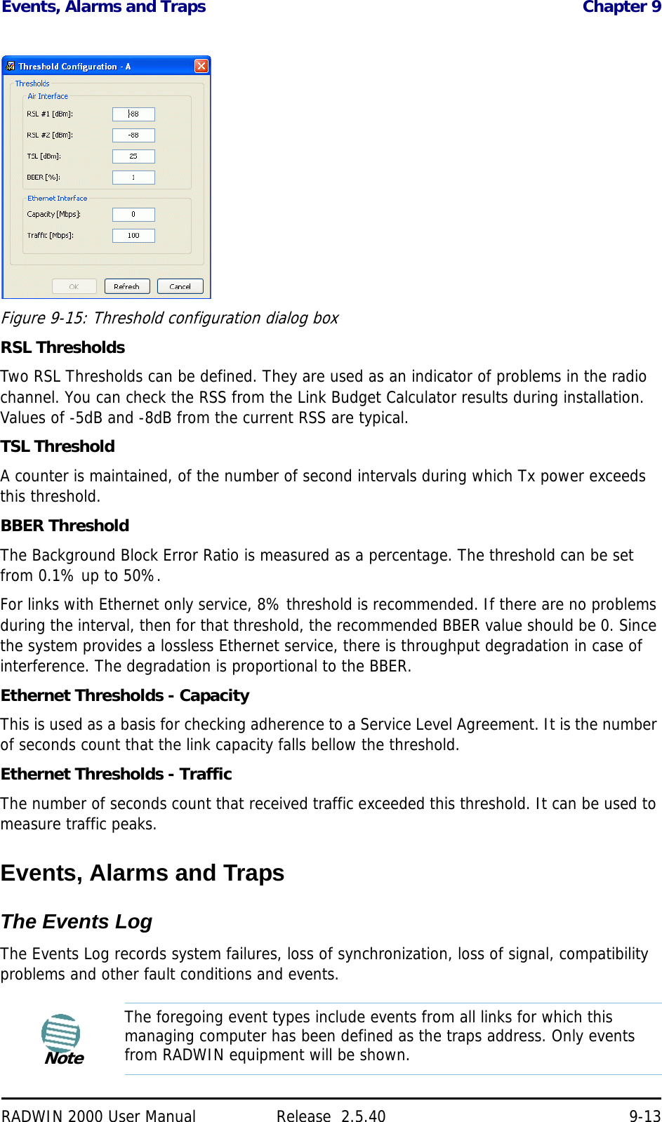
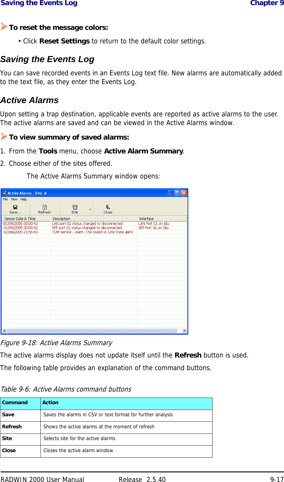
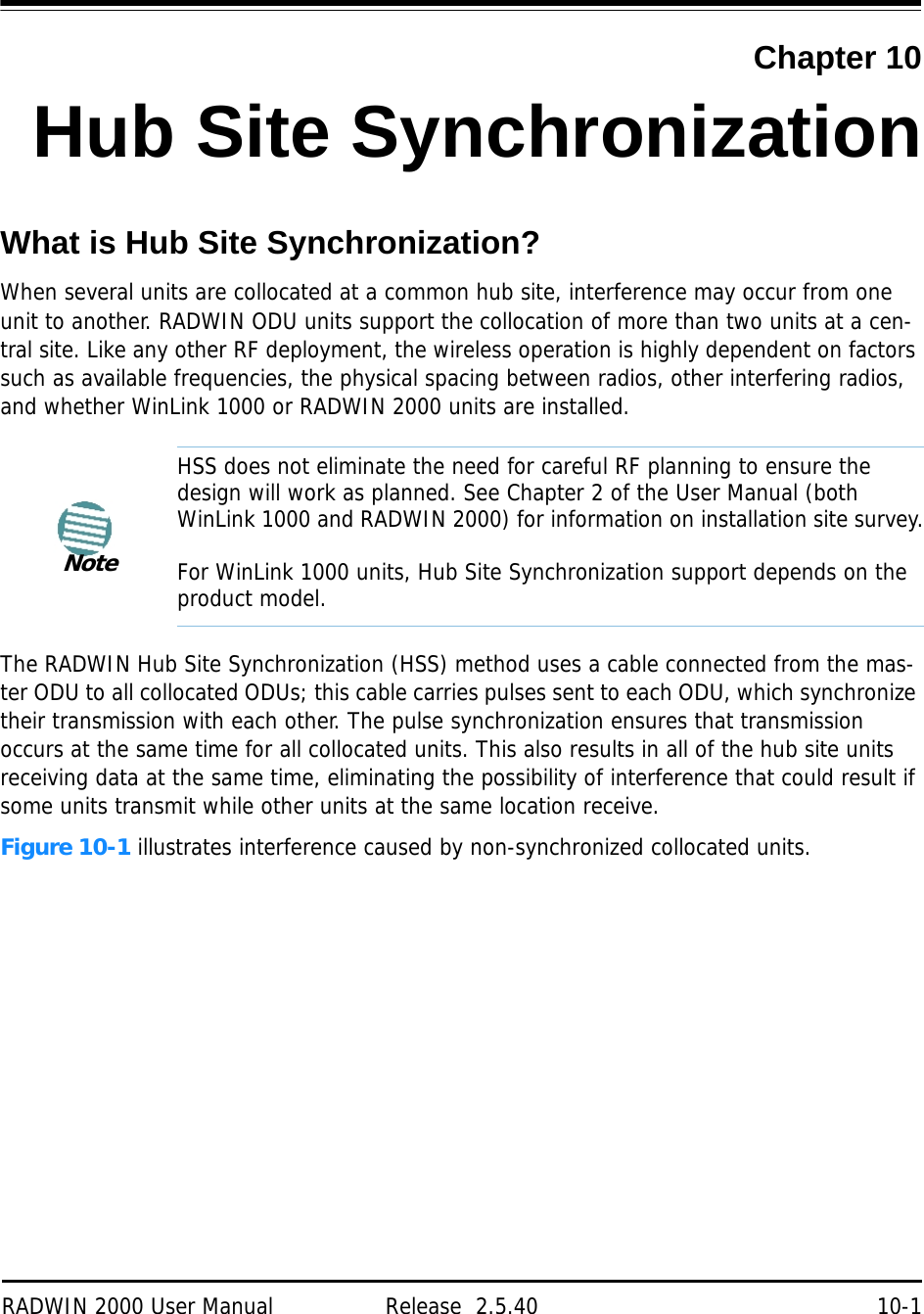
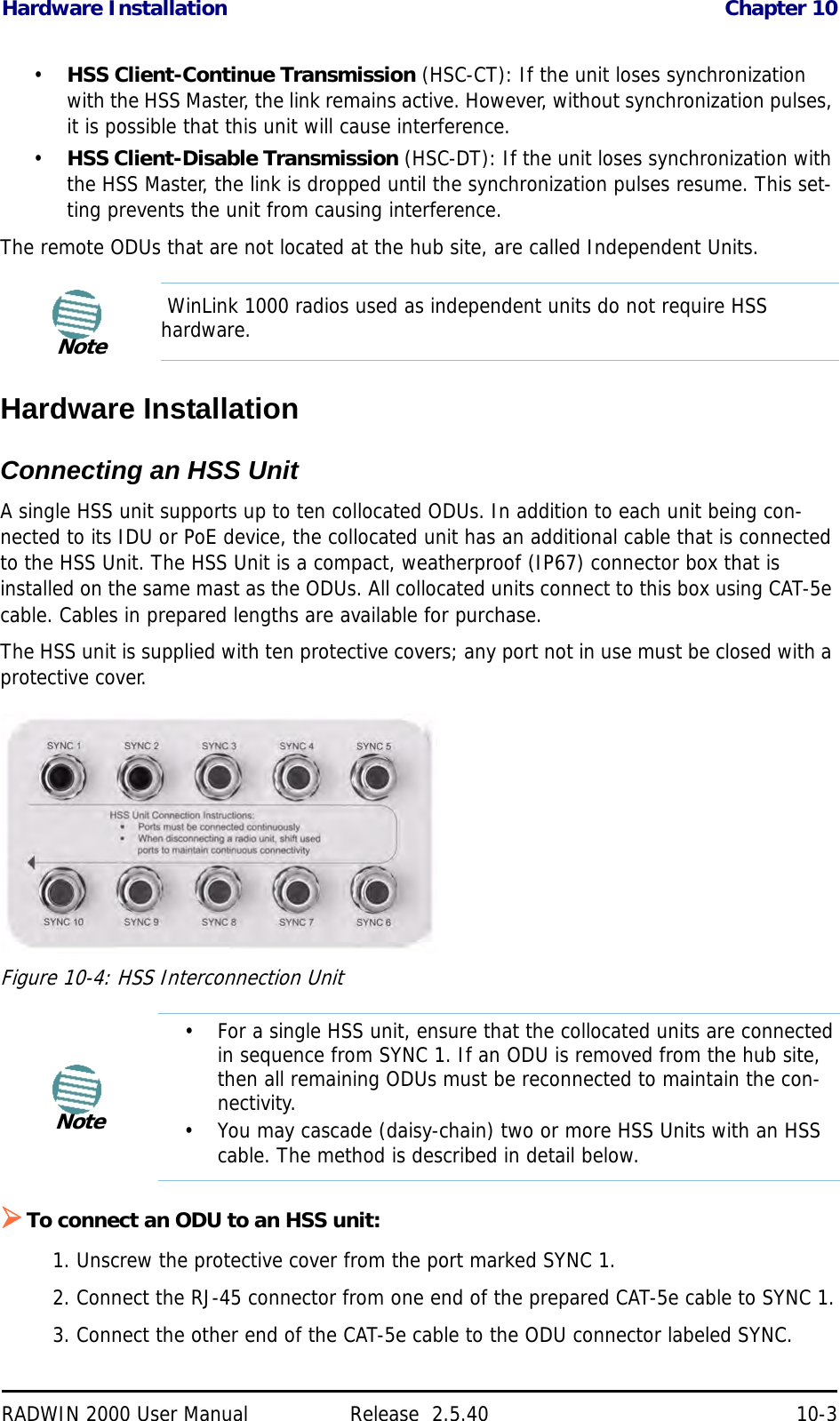
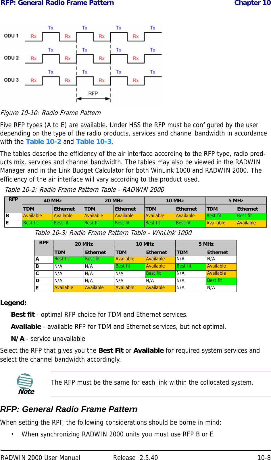
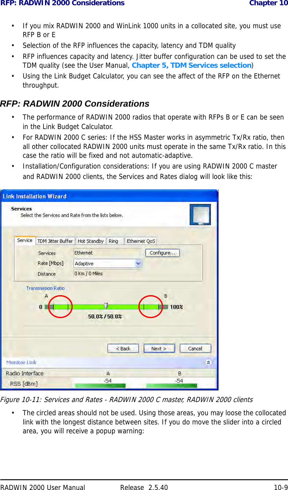
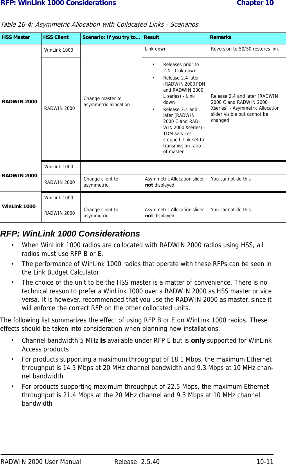
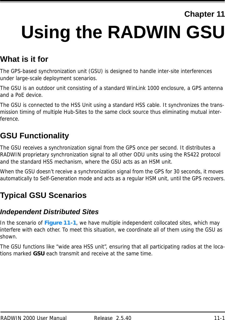
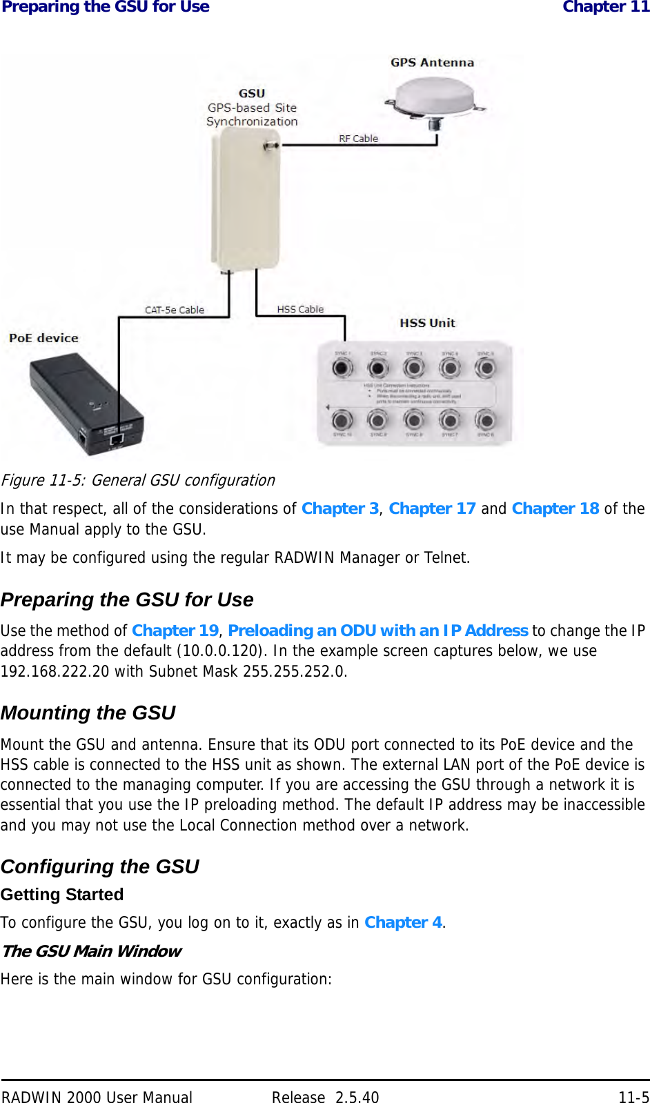
![Installation Chapter 5RADWIN 2000 User Manual Release 2.5.40 5-11The air rates used in this mode are same as when using single antennas in both sites.Table 5-2 summarizes the situation:The rates used by RADWIN 2000 are shown in Table 5-3 below:Table 5-2: MIMO - Diversity settingsNumber of Antennas Mode Graphic Indication Max Full Duplex CapacitySite A Site B2 2MIMO 50 MbpsDiversity 25 Mbps2 1 25 Mbps1 2 25 Mbps1 1 25 MbpsTable 5-3: RADWIN 2000 Air ratesAntenna Modulation FEC Air-Rate [Mbps]Single BPSK 1/2 6.5Single QPSK 1/2 13Single QPSK 3/4 19.5Single 16QAM 1/2 26Single 16QAM 3/4 39Single 64QAM 2/3 52Single 64QAM 3/4 58.5Single 64QAM 5/6 65Dual BPSK 1/2 13Dual QPSK 1/2 26Dual QPSK 3/4 39Dual 16QAM 1/2 52Dual 16QAM 3/4 78Dual 64QAM 2/3 104](https://usermanual.wiki/Radwin/RW2025.User-Manual-Part-1/User-Guide-1437358-Page-86.png)
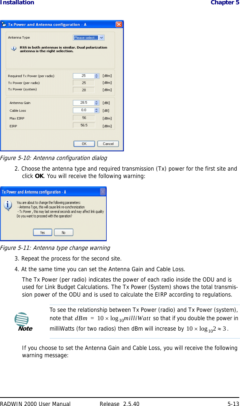
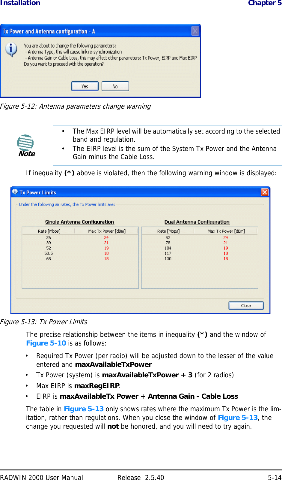
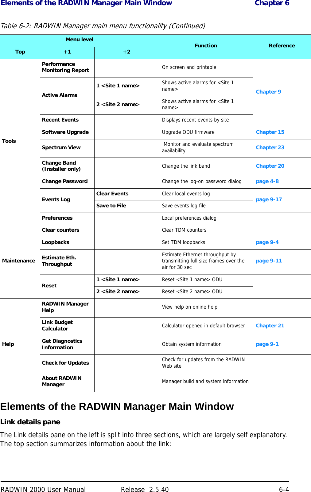
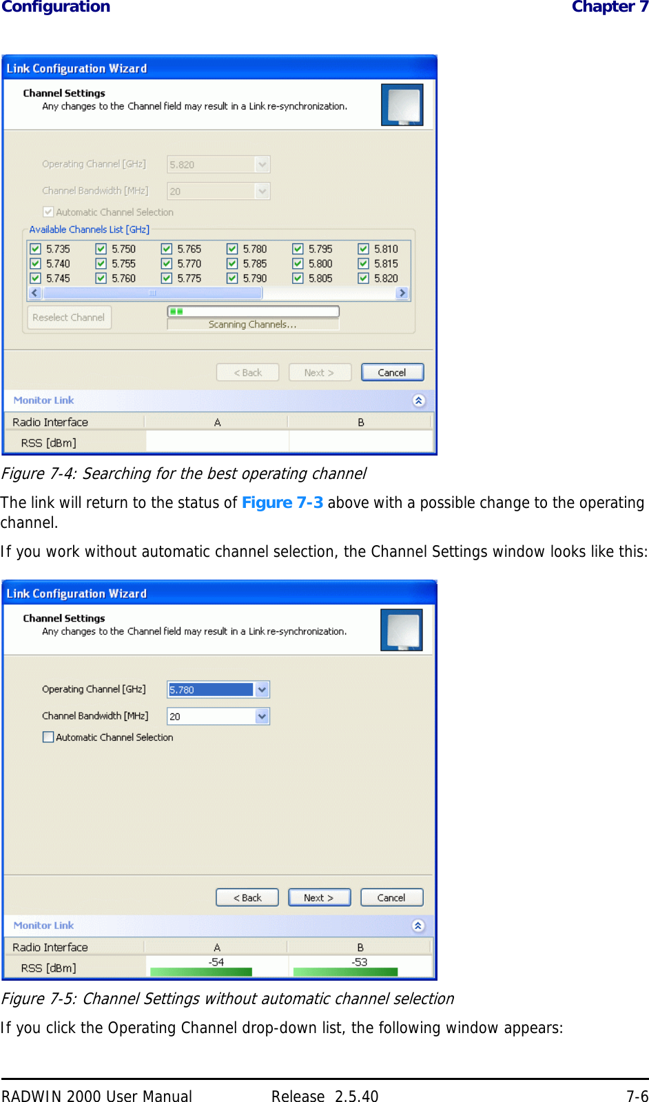
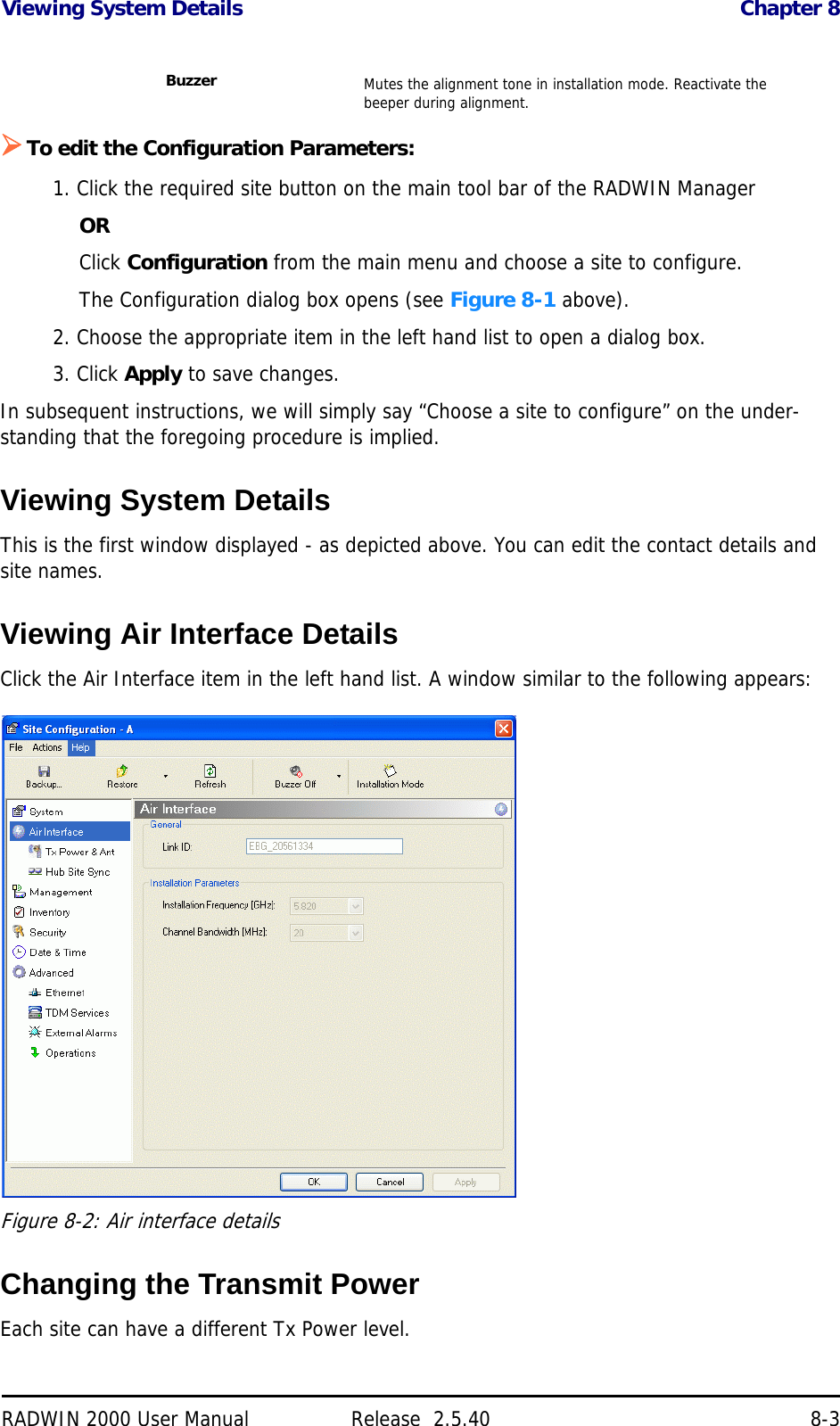
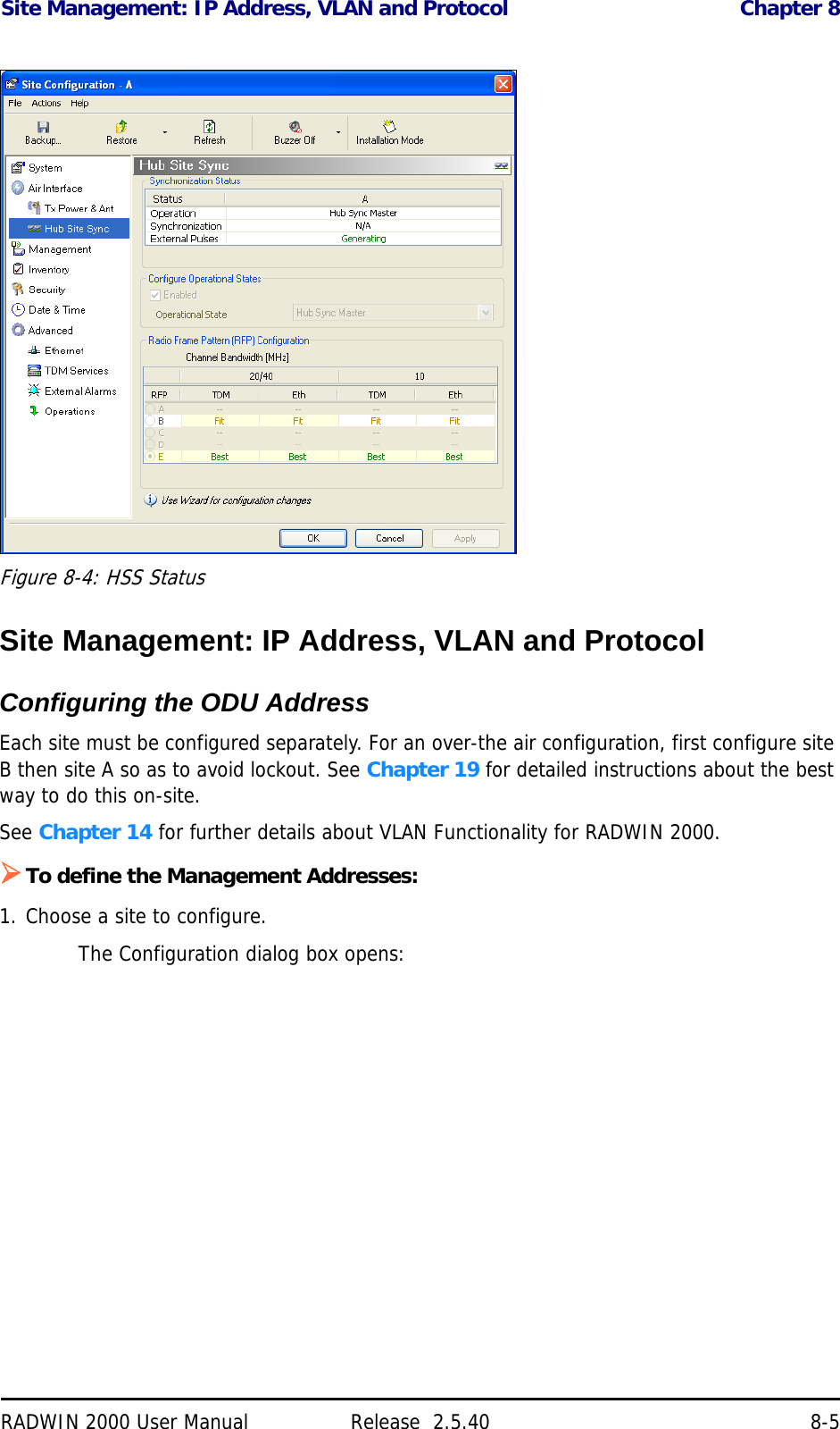
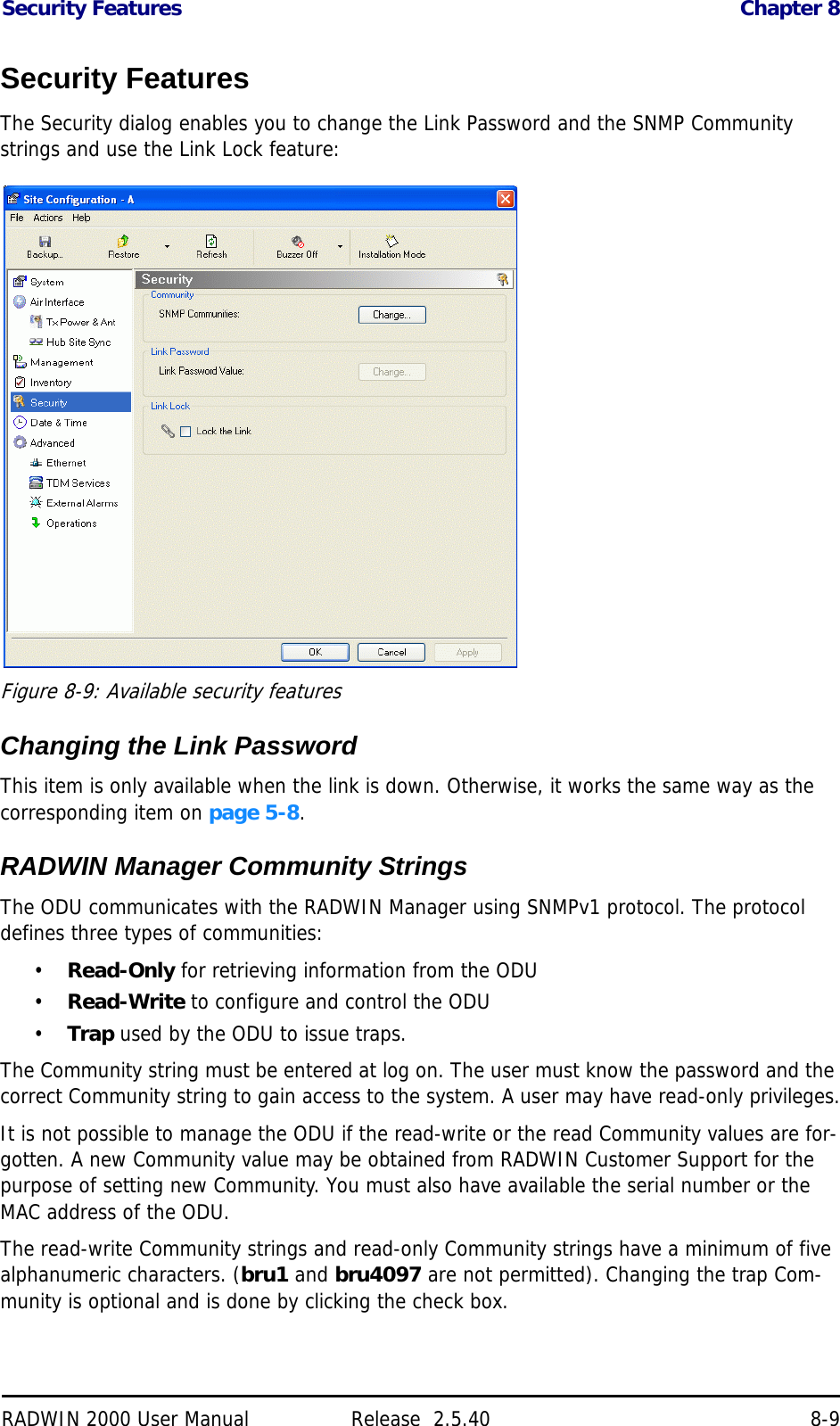
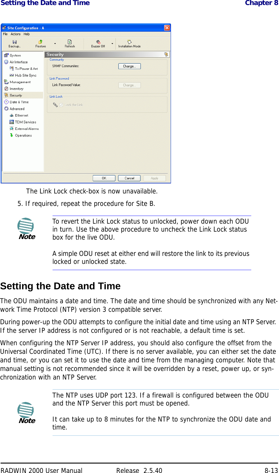
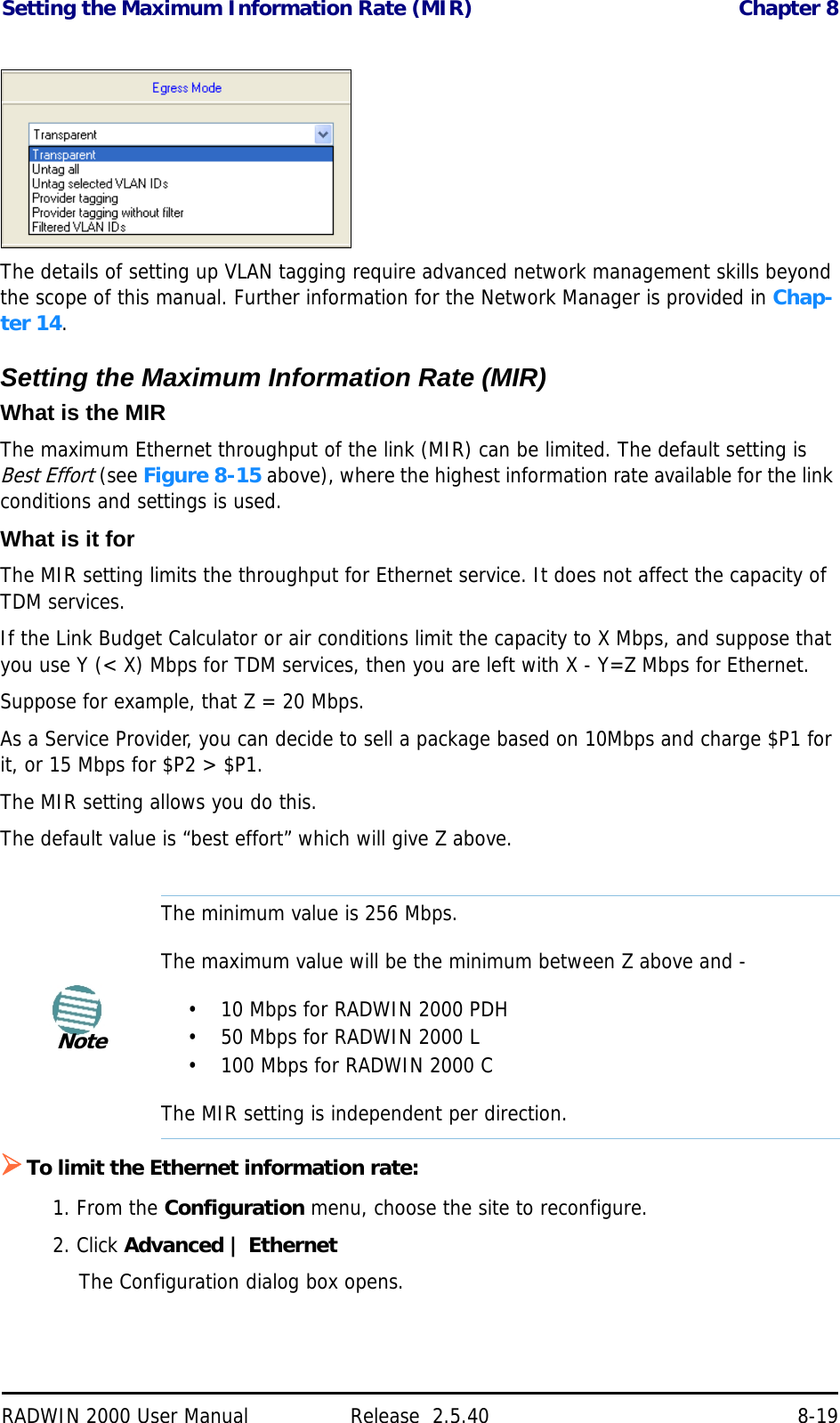
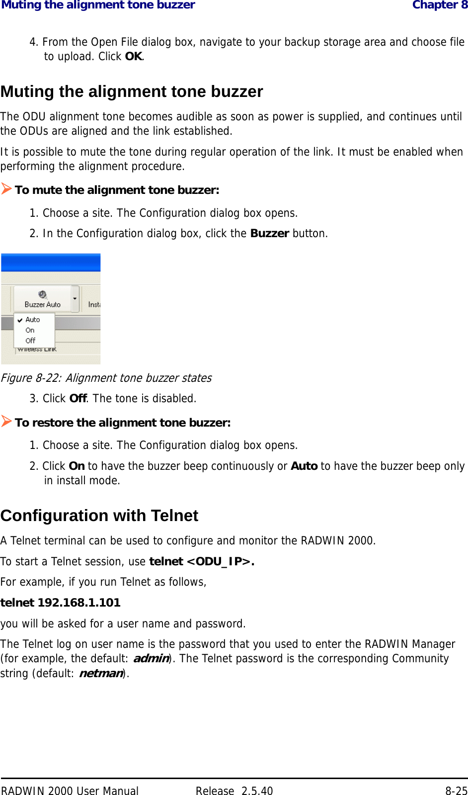
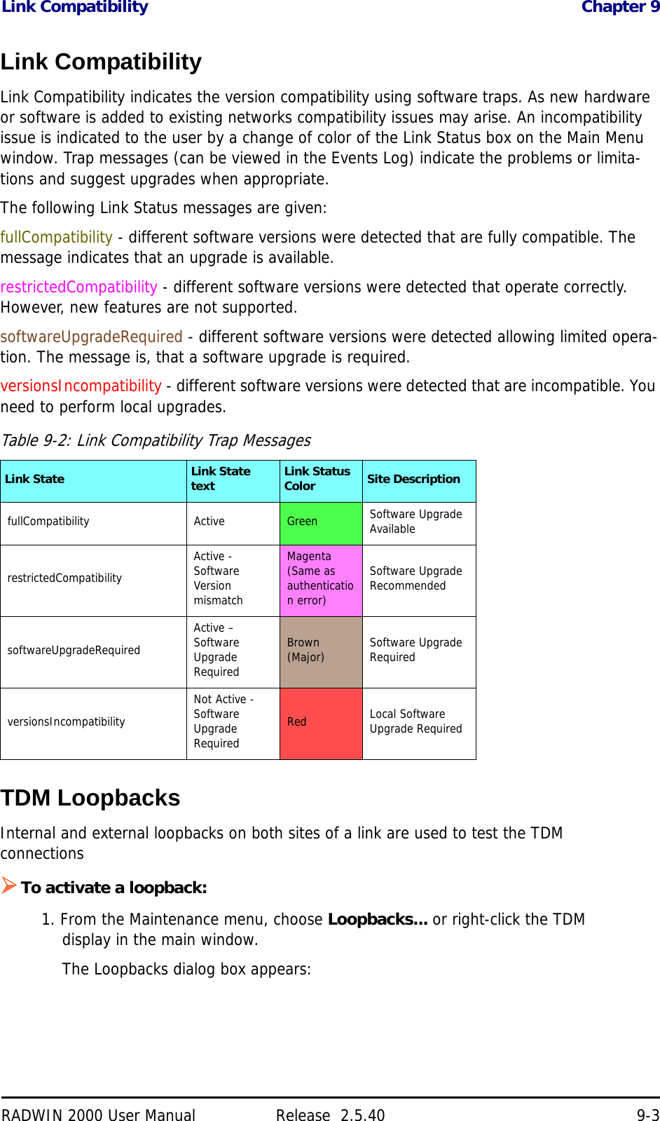
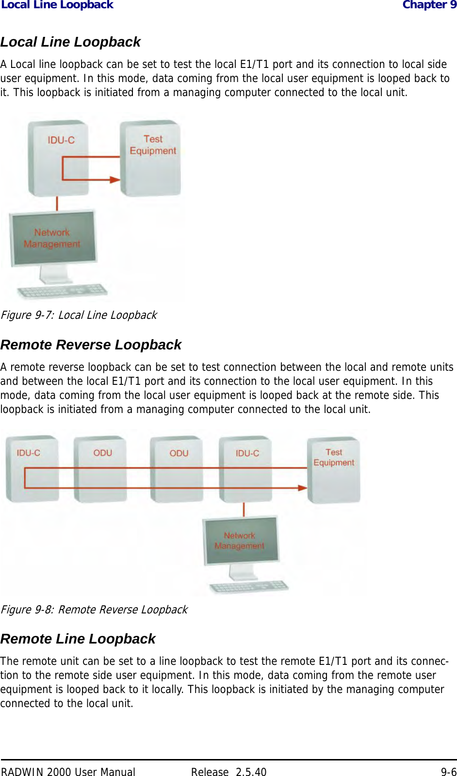
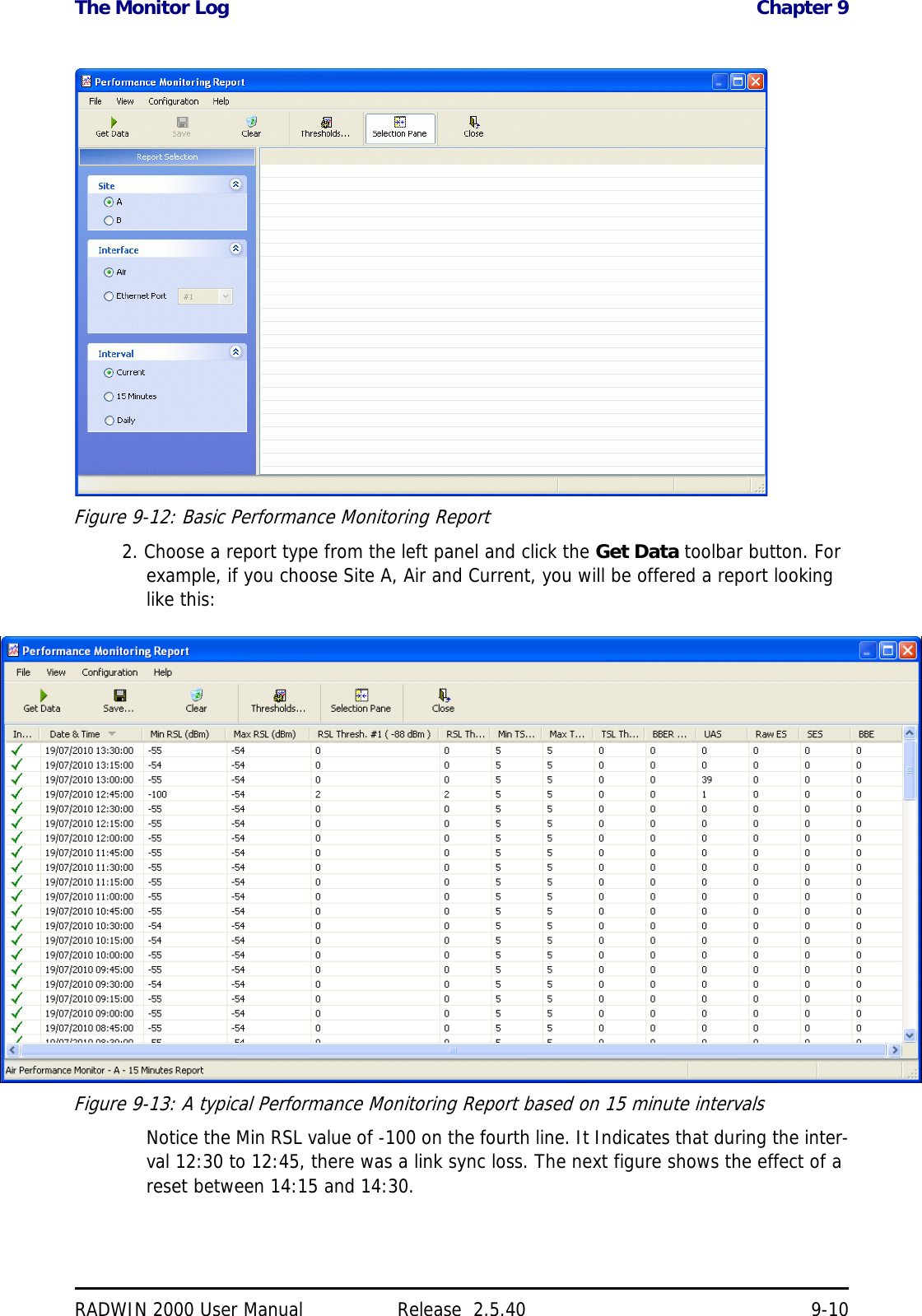
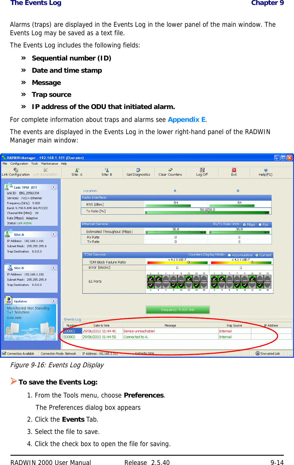
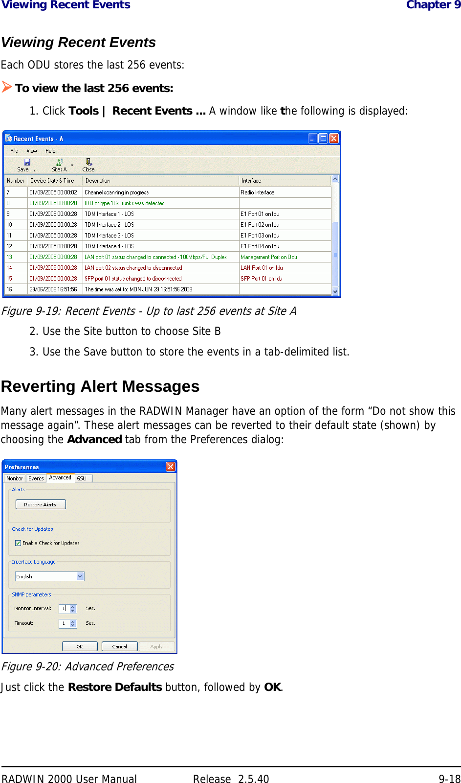
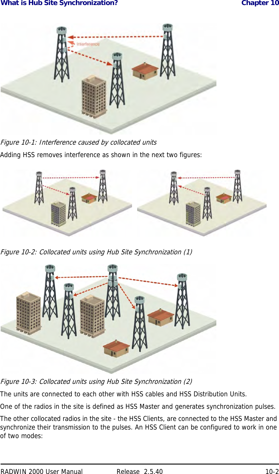
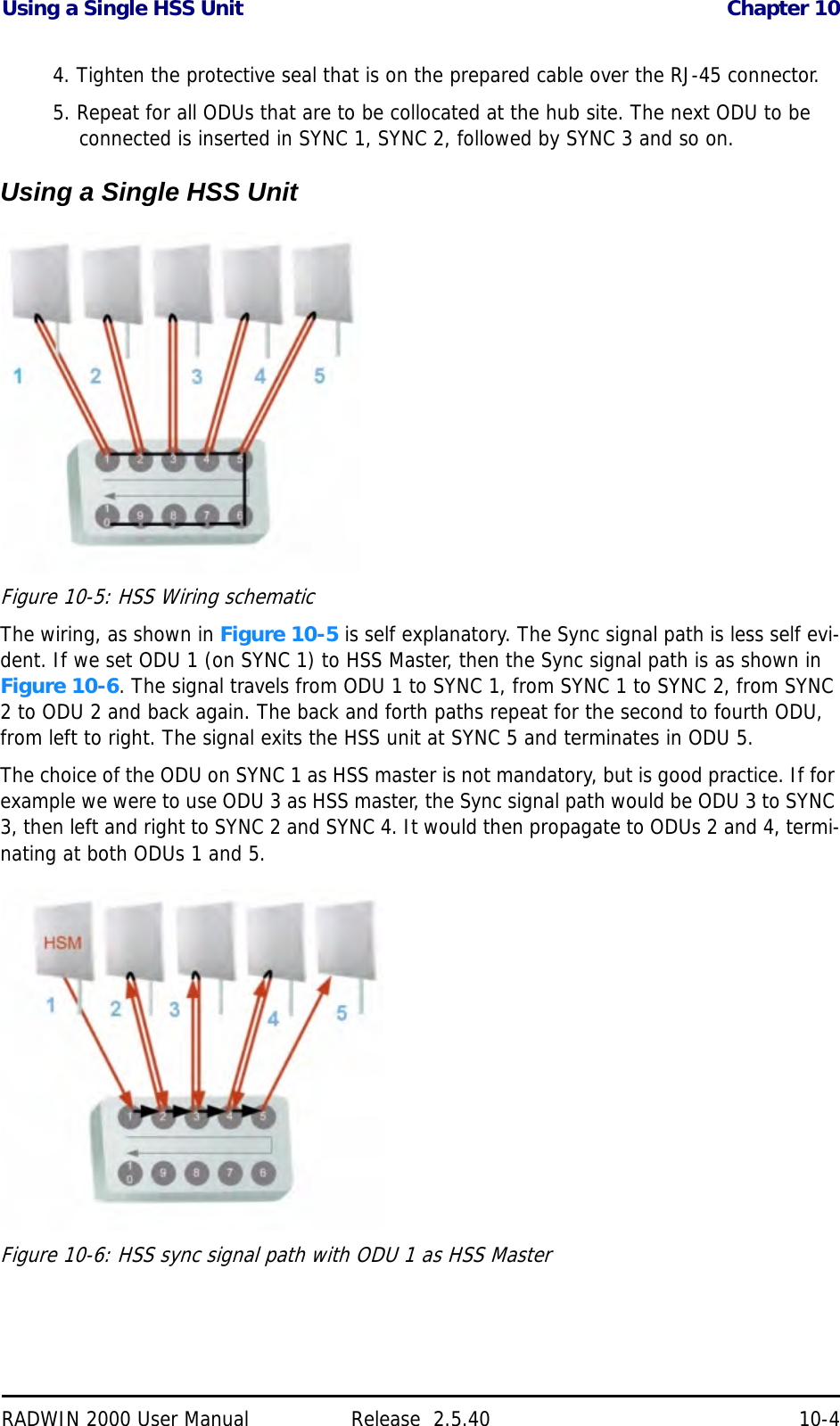
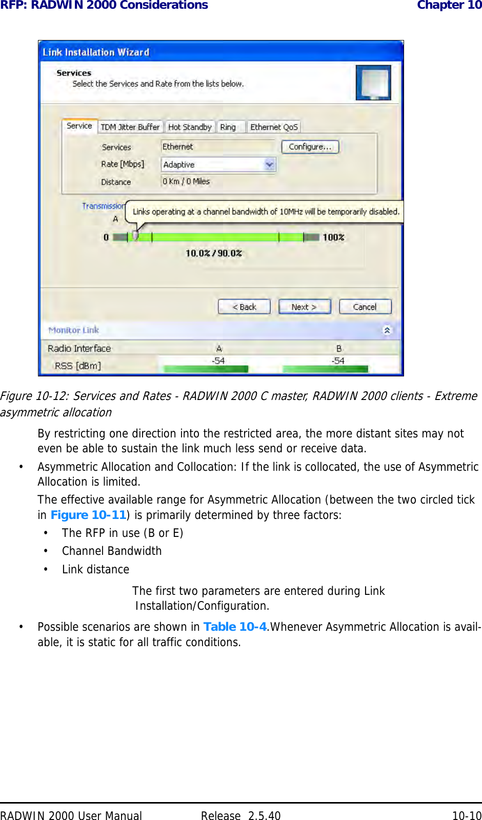
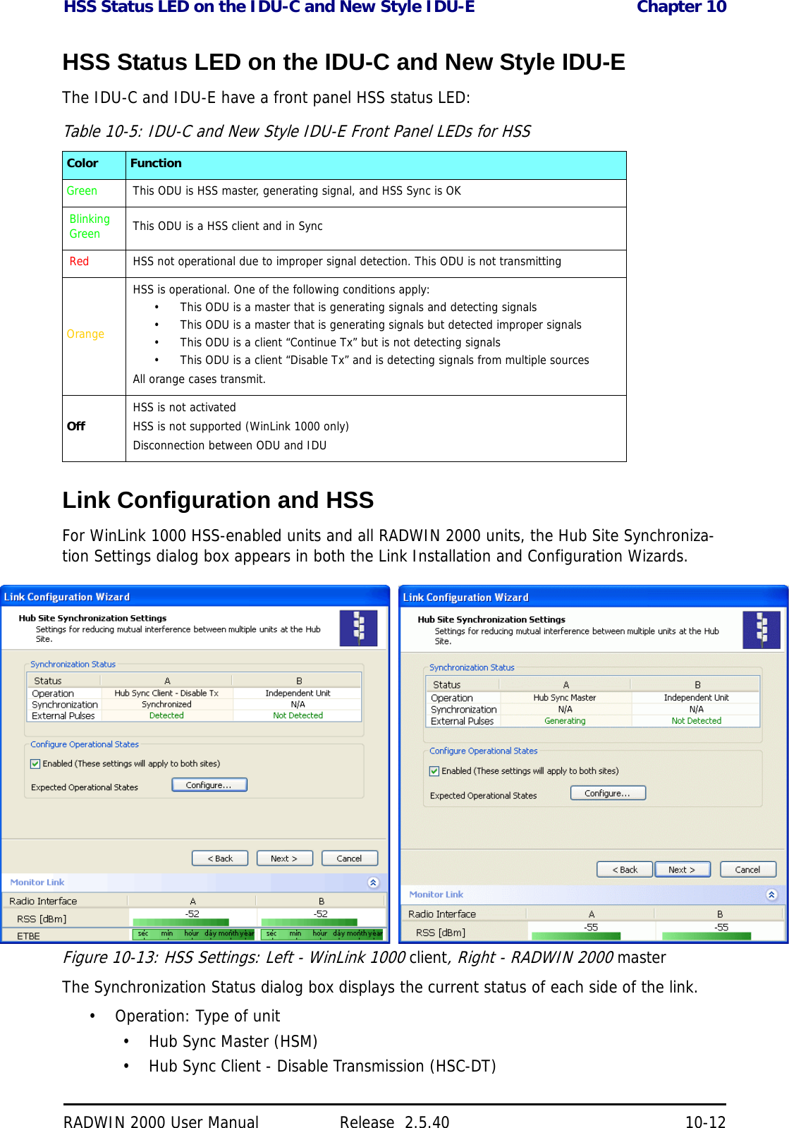
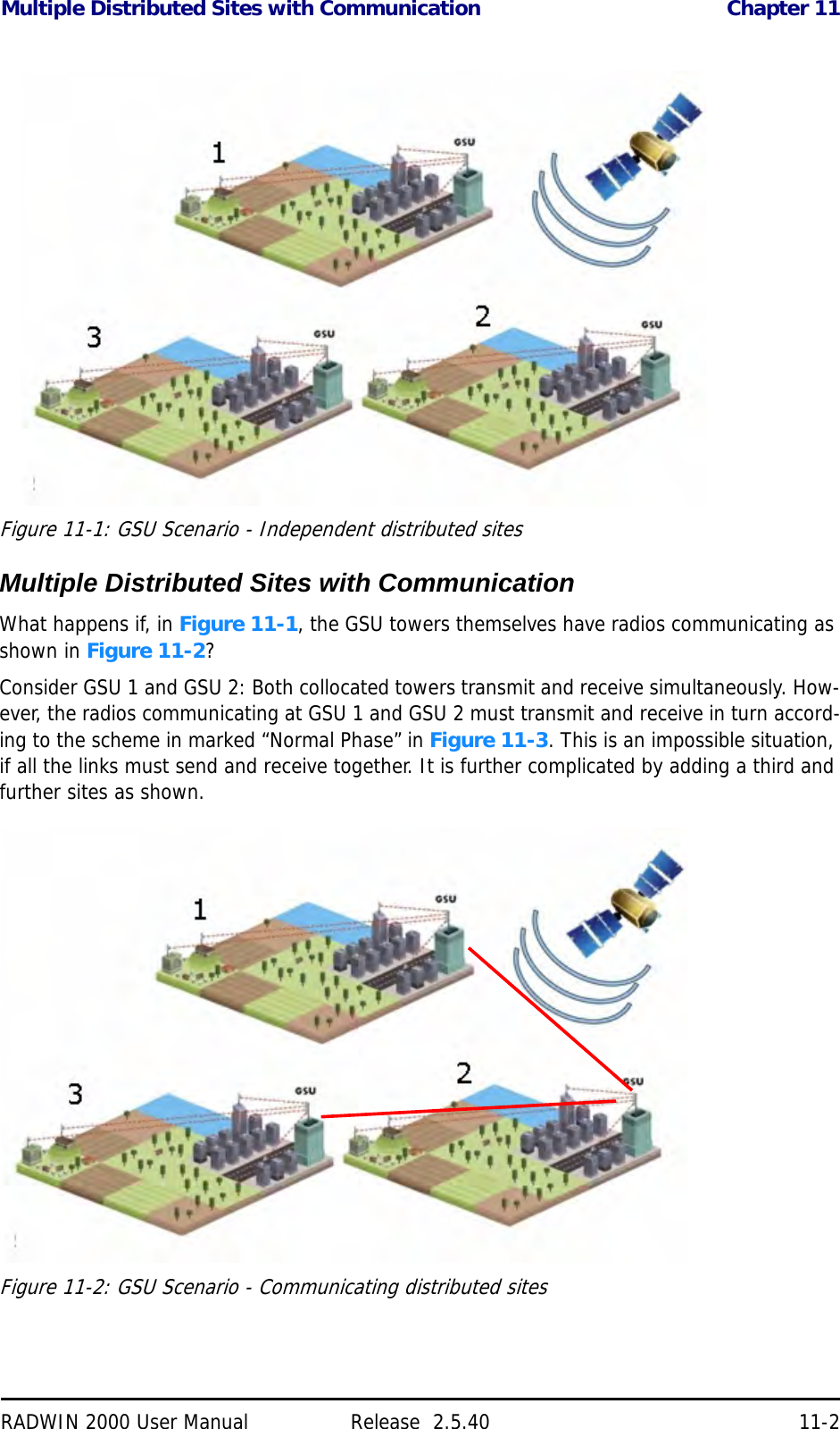
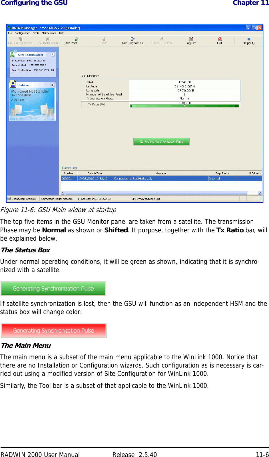
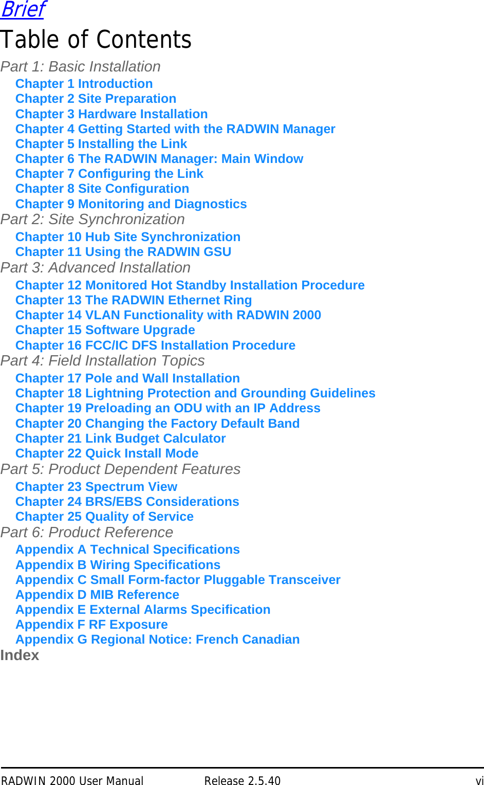
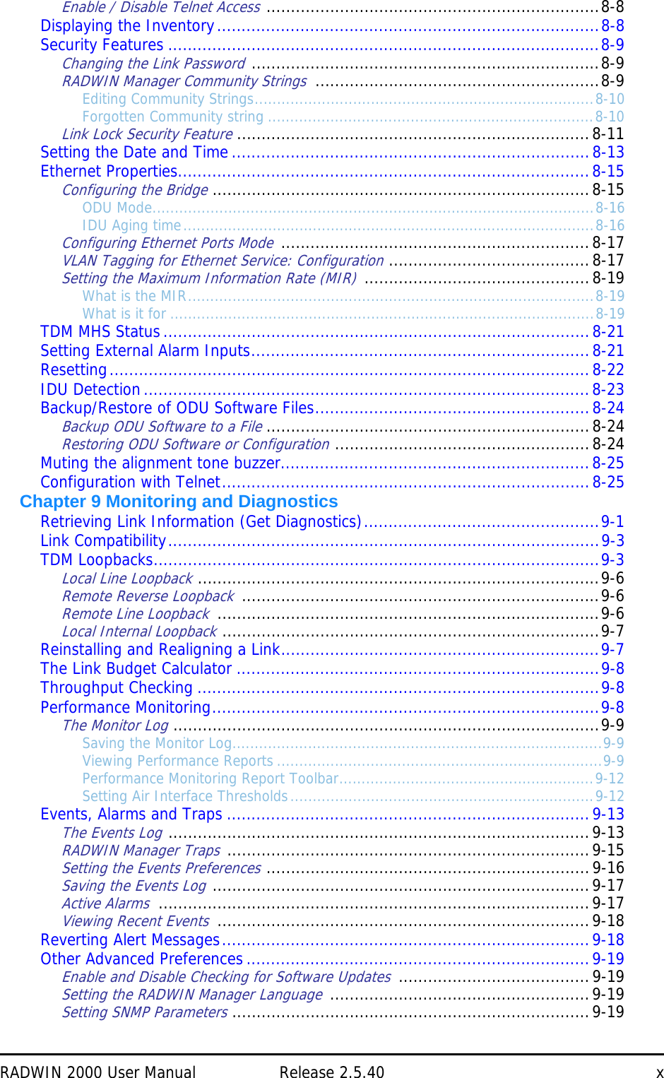
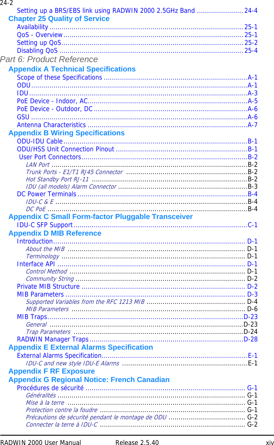
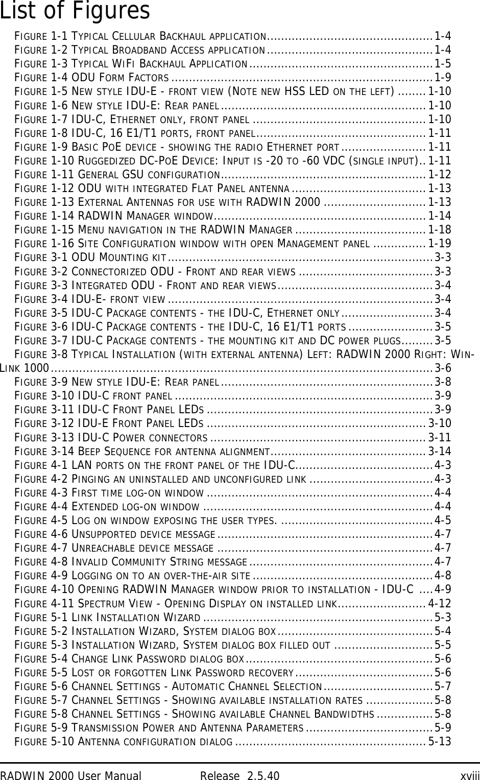
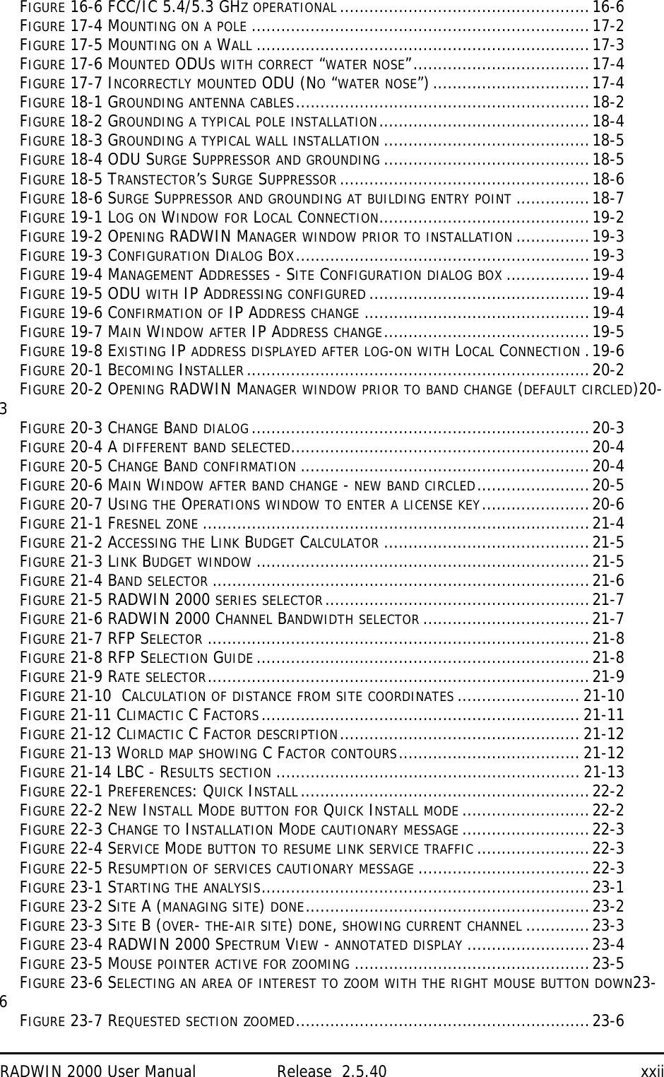
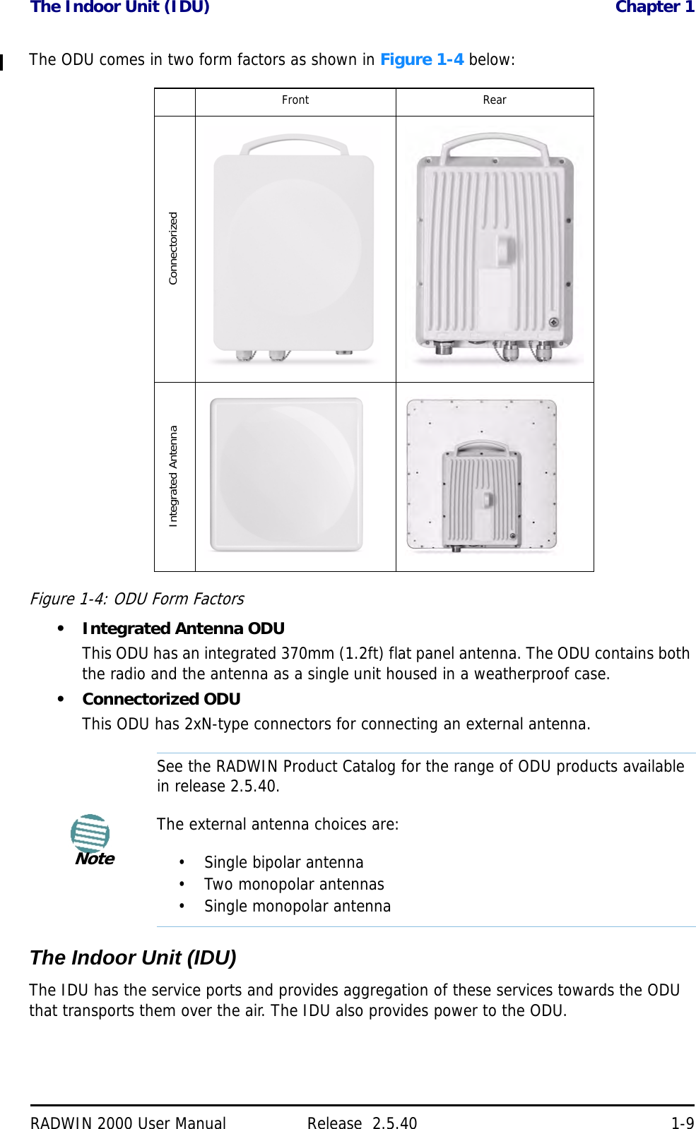
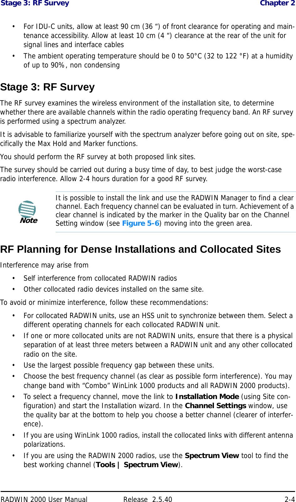
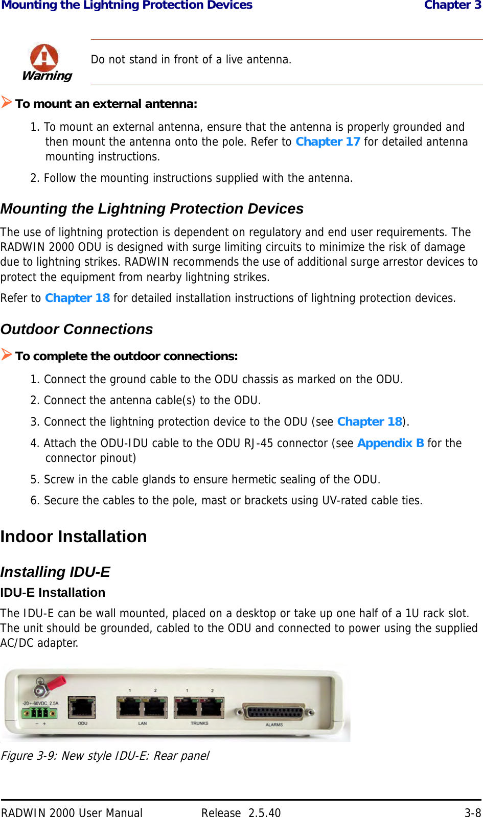
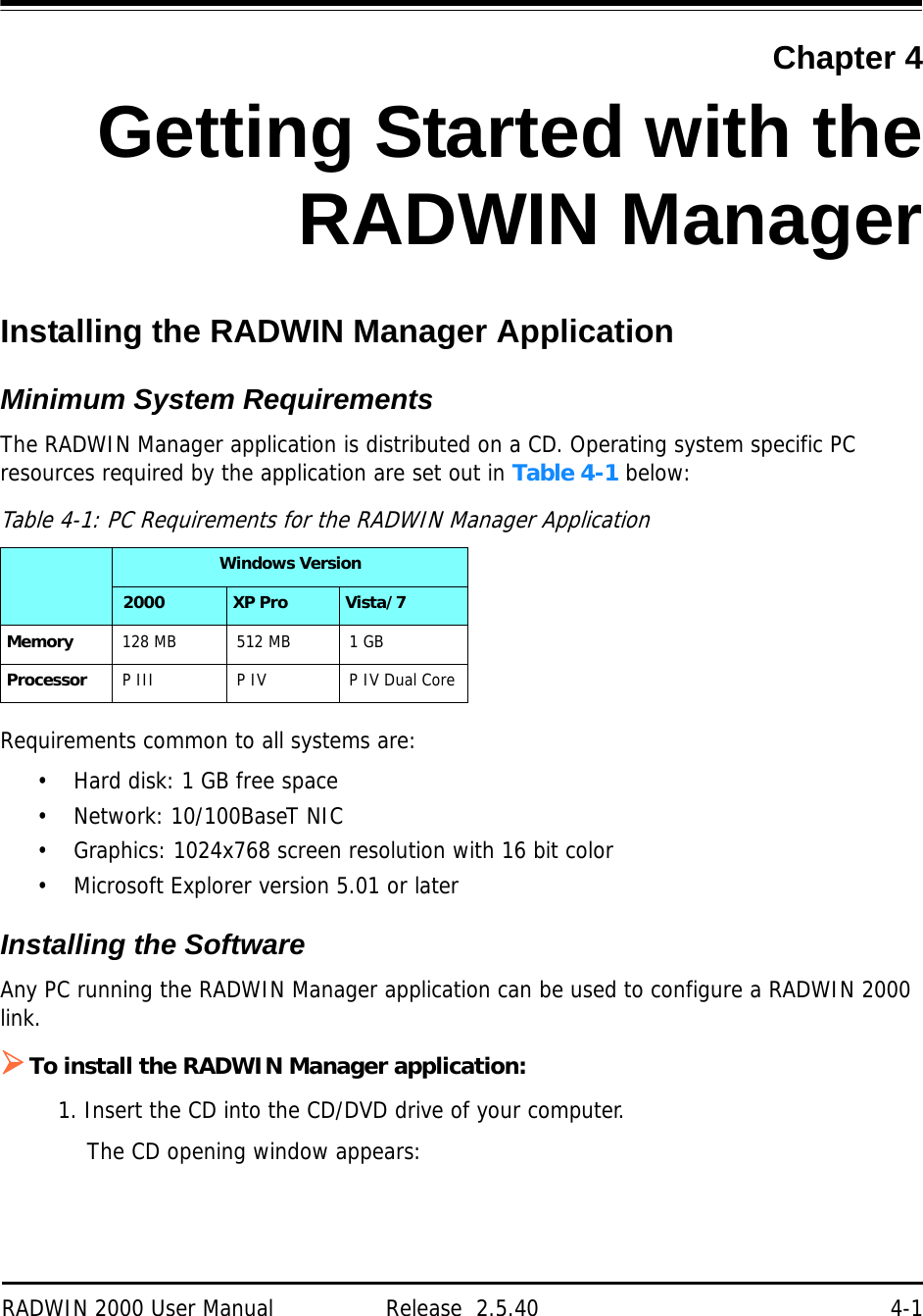
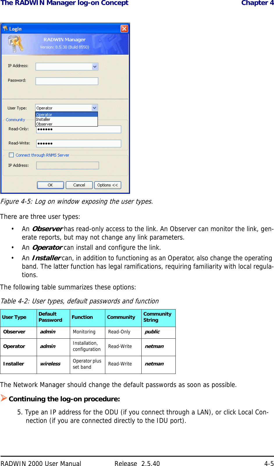
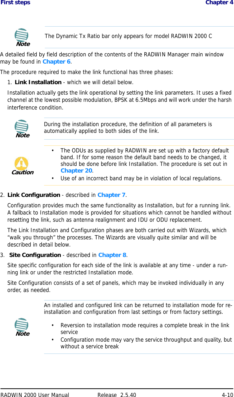
![Installation Chapter 5RADWIN 2000 User Manual Release 2.5.40 5-12Considerations for Changing Antenna ParametersLet:max Available Tx Power denote the maximum Tx Power practically available from an ODU. It appears as Tx Power per Radio in Figure 5-10 below.maxRegEIRP denote the maximum EIRP available by regulation. It will be determined by three factors:• per band/regulation• per channel bandwidth• antenna gainIt appears in Figure 5-10 as Max EIRP.maxRegTxPower denote the maximum regulatory Tx Power for the equipment, also having regard the above three points.Then, the following relationship must be satisfied: ... (*)These parameters are controlled as follows:To set Tx Power and configure antennas:1. Click the Configure buttons in turn to configure the antennas on both sides of the link. Each one offers a dialog like this:Dual 64QAM 3/4 117Dual 64QAM 5/6 130Table 5-3: RADWIN 2000 Air rates (Continued)Antenna Modulation FEC Air-Rate [Mbps]maxAvailableTxPower min maxRegEIRPAntennaGain CableLoss maxRegTxPower+– ()](https://usermanual.wiki/Radwin/RW2025.User-Manual-Part-1/User-Guide-1437358-Page-87.png)