Radwin RW2025 Outdoor radio unit operating in the 2.5-2.7 GHz (BRS) band User Manual STW
Radwin Ltd. Outdoor radio unit operating in the 2.5-2.7 GHz (BRS) band STW
Radwin >
Contents
- 1. User Manual Part 1
- 2. User Manual Part 2
User Manual Part 1

RADWIN 2000
Broadband Wireless Transmission System
USER MANUAL
RELEASES 2.5.40
UM 2000-2540/02.11

RADWIN 2000 User Manual Release 2.5.40 i
RADWIN 2000
User Manual
Notice
This manual contains information that is proprietary to RADWIN Ltd. (RADWIN hereafter). No
part of this publication may be reproduced in any form whatsoever without prior written
approval by RADWIN.
Right, title and interest, all information, copyrights, patents, know-how, trade secrets and
other intellectual property or other proprietary rights relating to this manual and to the
RADWIN products and any software components contained therein are proprietary products
of RADWIN protected under international copyright law and shall be and remain solely with
RADWIN.
The RADWIN name is a registered trademark of RADWIN Ltd. No right, license, or interest to
such trademark is granted hereunder, and you agree that no such right, license, or interest
shall be asserted by you with respect to such trademark.
You shall not copy, reverse compile or reverse assemble all or any portion of the User Manual
or any other RADWIN documentation or products. You are prohibited from, and shall not,
directly or indirectly, develop, market, distribute, license, or sell any product that supports
substantially similar functionality based or derived in any way from RADWIN products.Your
undertaking in this paragraph shall survive the termination of this Agreement.
This Agreement is effective upon your opening of a RADWIN product package and shall
continue until terminated. RADWIN may terminate this Agreement upon the breach by you of
any term thereof. Upon such termination by RADWIN, you agree to return to RADWIN any
RADWIN products and documentation and all copies and portions thereof.
For further information contact RADWIN at one of the addresses under Worldwide
Contacts below or contact your local distributor.
Disclaimer
The parameters quoted in this document must be specifically confirmed in writing before they
become applicable to any particular order or contract. RADWIN reserves the right to make
alterations or amendments to the detail specification at its discretion. The publication of
information in this document does not imply freedom from patent or other rights of RADWIN,
or others.
Trademarks
WinLink 1000 and RADWIN 2000 are trademarks of RADWIN Ltd.
Windows 2000, XP Pro, Vista, Windows 7 and Internet Explorer are trademarks
of Microsoft Inc.
Mozilla and Firefox are trademarks of the Mozilla Foundation.
Other product names are trademarks of their respective manufacturers.

RADWIN 2000 User Manual Release 2.5.40 ii
RADWIN Worldwide Offices
Corporate and EMEA Regional Headquarters
Corporate and EMEA Headquarters
27 Habarzel Street
Tel Aviv, 69710
Israel
Tel: +972.3.766.2900
Fax: +972.3.766.2902
Email: sales@radwin.com
North America Regional
Headquarters
900 Corporate Drive
Mahwah, NJ, 07430
USA
Tel: +1-877-RADWIN US
(+1-877 723-9468)
Tel: +1-201-252-4224
Fax: +1-201-621-8911
Email: salesna@radwin.com
Customer Support - North America:
Hours: 9 am - 6 pm EST (Mon - Fri)
Email: supportusa@radwin.com
APAC Regional Headquarters
53A, Grange Road #15-02
Spring Grove ,249566
Singapore
Tel: +65.6638.7864
Email: salessg@radwin.com
RADWIN Regional Offices
RADWIN Brazil
Av. Chucri Zaidan, 920 – 9º
São Paulo, 04583-904
Brazil
Tel: +55.11.3048-4110
Email: salesbr@radwin.com
RADWIN Mexico
Quinto #20 Col El Centinela
Mexico, DF, O4450
Mexico
Tel: +52 (55) 5689 8970
Email: salesmx@radwin.com
RADWIN Peru
Av. Antares 213
Lima, 33
Peru
Tel: +511.6285105
Fax: +511-990304095
Email: salespe@radwin.com
RADWIN India
E-13,B-1 Extn., Mohan Co-operative Industrial Estate
New Delhi, 110 044
India
Tel: +91-11-40539178
Email: salesin@radwin.com
RADWIN Philippines
5 Bur Bank St.
Laguna, Belair, Santa Rosa
Laguna Philippines
Tel: +63 928 7668230
Email: salesph@radwin.com
RADWIN South Africa
P.O. Box 3554, Rivonia
Johannesburg ,2128
South Africa
Tel: +27 (0)82 551 5600
Email: sales@radwin.com
RADWIN Italy and Spain
Piazza Arenella 7/H
Napoli ,80128
Italy
Tel:+390815564116
Fax: +39335433620
Email: salesit@radwin.com
RADWIN Central America
Calle La Cañada # 108-E
Jardines de la Hacienda
Ciudad Merliot El Salvador
Tel: +503 2278-5628
Email: sales@radwin.com
RADWIN South East Asia
All Season Mansion
87/38 Wireless Road Lumpinee
Bangkok ,10330
Thailand
Tel: +66811707503
Email: sales@radwin.com

RADWIN 2000 User Manual Release 2.5.40 iii
Regulatory Compliance
General Note
This system has achieved Type Approval in various countries around the world. This means
that the system has been tested against various local technical regulations and found to
comply. The frequency bands in which the system operates may be “unlicensed” and in these
bands, the system can be used provided it does not cause interference.
FCC - Compliance
This equipment has been tested and found to comply with the limits for a Class B digital
device, pursuant to Part 15 of the FCC Rules. These limits are designed to provide reasonable
protection against harmful interference in a residential installation. This equipment generates,
uses and can radiate radio frequency energy and, if not installed and used in accordance with
the instructions, may cause harmful interference to radio communications. However, there is
no guarantee that interference will not occur in a particular installation. If this equipment
does cause harmful interference to radio or television reception, which can be determined by
turning the equipment off and on, the user is encouraged to try to correct the interference by
one or more of the following measures:
• Reorient or relocate the receiving antenna.
• Increase the separation between the equipment and receiver.
• Connect the equipment into an outlet on a circuit different from that to which the
receiver is connected.
Consult the dealer or an experienced radio/TV technician for help.
Changes or modifications to this equipment not expressly approved by the party responsible
for compliance could void the user's authority to operate the equipment.
Warning
It is the responsibility of the installer to ensure that when using the outdoor
antenna kits in the United States (or where FCC rules apply), only those
antennas certified with the product are used. The use of any antenna other
than those certified with the product is expressly forbidden by FCC rules 47
CFR part 15.204.
Warning
It is the responsibility of the installer to ensure that when configuring the
radio in the United States (or where FCC rules apply), the Tx power is set
according to the values for which the product is certified. The use of Tx
power values other than those, for which the product is certified, is
expressly forbidden by FCC rules 47 CFR part 15.204.
Caution
Outdoor units and antennas should be installed ONLY by experienced
installation professionals who are familiar with local building and safety
codes and, wherever applicable, are licensed by the appropriate
government regulatory authorities. Failure to do so may void the product
warranty and may expose the end user or the service provider to legal and
financial liabilities. Resellers or distributors of this equipment are not liable
for injury, damage or violation of regulations associated with the installation
of outdoor units or antennas. The installer should configure the output
power level of antennas according to country regulations and antenna type.

RADWIN 2000 User Manual Release 2.5.40 iv
Indoor Units comply with part 15 of the FCC rules. Operation is subject to the following two
conditions:
(1) These devices may not cause harmful interference.
(2) These devices must accept any interference received, including interference that may
cause undesired operation.
Canadian Emission Requirements for Indoor Units
This Class B digital apparatus complies with Canadian ICES-003.
Cet appareil numẻrique de la classe B est conforme ả la norme NMB-003 du Canada.
China MII
Operation of the equipment is only allowed under China MII 5.8GHz band regulation
configuration with EIRP limited to 33 dBm (2 Watt).
India WPC
Operation of the equipment is only allowed under India WPC GSR-38 for 5.8GHz band
regulation configuration.
Unregulated
In countries where the radio is not regulated the equipment can be operated in any regulation
configuration, best results will be obtained using Universal regulation configuration.
Safety Practices
Applicable requirements of National Electrical Code (NEC), NFPA 70; and the National
Electrical Safety Code, ANSI/IEEE C2, must be considered during installation.
NOTES:
1. A Primary Protector is not required to protect the exposed wiring as long as the exposed
wiring length is limited to less than or equal to 140 feet, and instructions are provided to
avoid exposure of wiring to accidental contact with lightning and power conductors in
accordance with NEC Sections 725-54 (c) and 800-30.
In all other cases, an appropriate Listed Primary Protector must be provided. Refer to Articles
800 and 810 of the NEC for details.
2. For protection of ODU against direct lightning strikes, appropriate requirements of NFPA
780 should be considered in addition to NEC.
Warning
• Where Outdoor units are configurable by software to Tx power values
other than those for which the product is certified, it is the responsi-
bility of the Professional Installer to restrict the Tx power to the certi-
fied limits.
• The RADWIN 2000 2.5GHz BAND device (FCC ID: Q3KRW2025) com-
plies with FCC RF radiation exposure limits. This equipment should be
installed and operated with a minimum distance of 104.6cm between
the radiator and your body for 2.5 GHz operations
• This product was tested with special accessories - indoor unit (IDU or
PoE), FTP CAT-5e shielded cable with sealing gasket, 12 AWG
grounding cable - which must be used with the unit to insure compli-
ance.

RADWIN 2000 User Manual Release 2.5.40 v
3. For Canada, appropriate requirements of the CEC 22.1 including Section 60 and additional
requirements of CAN/CSA-B72 must be considered as applicable.

RADWIN 2000 User Manual Release 2.5.40 vi
Brief
Table of Contents
Part 1: Basic Installation
Chapter 1 Introduction
Chapter 2 Site Preparation
Chapter 3 Hardware Installation
Chapter 4 Getting Started with the RADWIN Manager
Chapter 5 Installing the Link
Chapter 6 The RADWIN Manager: Main Window
Chapter 7 Configuring the Link
Chapter 8 Site Configuration
Chapter 9 Monitoring and Diagnostics
Part 2: Site Synchronization
Chapter 10 Hub Site Synchronization
Chapter 11 Using the RADWIN GSU
Part 3: Advanced Installation
Chapter 12 Monitored Hot Standby Installation Procedure
Chapter 13 The RADWIN Ethernet Ring
Chapter 14 VLAN Functionality with RADWIN 2000
Chapter 15 Software Upgrade
Chapter 16 FCC/IC DFS Installation Procedure
Part 4: Field Installation Topics
Chapter 17 Pole and Wall Installation
Chapter 18 Lightning Protection and Grounding Guidelines
Chapter 19 Preloading an ODU with an IP Address
Chapter 20 Changing the Factory Default Band
Chapter 21 Link Budget Calculator
Chapter 22 Quick Install Mode
Part 5: Product Dependent Features
Chapter 23 Spectrum View
Chapter 24 BRS/EBS Considerations
Chapter 25 Quality of Service
Part 6: Product Reference
Appendix A Technical Specifications
Appendix B Wiring Specifications
Appendix C Small Form-factor Pluggable Transceiver
Appendix D MIB Reference
Appendix E External Alarms Specification
Appendix F RF Exposure
Appendix G Regional Notice: French Canadian
Index

RADWIN 2000 User Manual Release 2.5.40 vii
Full
Table of Contents
Notice.............................................................................................................................i
RADWIN Worldwide Offices............................................................................................. ii
Regulatory Compliance....................................................................................................iii
Part 1: Basic Installation
Chapter 1 Introduction
Welcome to RADWIN 2000!.........................................................................1-1
RADWIN 2000 highlights:............................................................................ 1-1
What’s new in Release 2.5.40 ......................................................................1-2
Terminology
............................................................................................ 1-2
More About New and Extended RADWIN 2000 Products
...................................1-2
RADWIN 2000 C-series 3.X Products...............................................................1-2
RADWIN 2000 C-series BRS Products..............................................................1-3
RADWIN 2000 X-series for 3.X Products.........................................................1-3
Summary......................................................................................................1-3
Key Applications..........................................................................................1-4
Cellular Backhaul
..................................................................................... 1-4
Broadband Access
................................................................................... 1-4
Mobility Applications
.................................................................................1-5
Border Control...............................................................................................1-5
Installation Security.......................................................................................1-5
Railway solutions...........................................................................................1-5
Key Features of RADWIN 2000
..................................................................1-5
Components of a RADWIN 2000 Link............................................................1-8
The Outdoor Unit (ODU)
............................................................................ 1-8
The Indoor Unit (IDU)
...............................................................................1-9
New style IDU-E for both WinLink 1000 and RADWIN 2000 ............................ 1-10
IDU-C......................................................................................................... 1-10
Power Over Ethernet (PoE) Devices
........................................................... 1-11
Basic PoE Device ......................................................................................... 1-11
GSU
.................................................................................................... 1-11
Antennas
.............................................................................................. 1-12
RADWIN Manager
.................................................................................. 1-13
RADWIN Network Management System (RNMS)
.......................................... 1-14
Accessories
........................................................................................... 1-14
.......................................................................................................... 1-15
Documentation supplied with RADWIN 2000
................................................ 1-15
How to Use this Manual............................................................................. 1-15
A Little Terminology................................................................................. 1-16
Conventions Used in this Manual................................................................ 1-17
Notifications
.......................................................................................... 1-17
Typographical conventions
....................................................................... 1-17
General....................................................................................................... 1-17
Software..................................................................................................... 1-17
Windows Terminology
............................................................................. 1-18
Viewing and Printing
............................................................................... 1-19
Chapter 2 Site Preparation
Planning the Link Site.................................................................................. 2-1
Overview
................................................................................................ 2-1
The Site Survey .......................................................................................... 2-1
Introduction
............................................................................................ 2-1
Recommended Equipment
......................................................................... 2-1
Stage 1: Preliminary Survey......................................................................... 2-2

RADWIN 2000 User Manual Release 2.5.40 viii
Stage 2: Physical Survey..............................................................................2-3
Additional Outdoor Site Requirements
...........................................................2-3
Additional Indoor Site Requirements
.............................................................2-3
Stage 3: RF Survey......................................................................................2-4
RF Planning for Dense Installations and Collocated Sites ................................2-4
Chapter 3 Hardware Installation
Safety Practices...........................................................................................3-1
Preventing overexposure to RF energy
..........................................................3-1
Grounding
...............................................................................................3-1
Protection against Lightning
.......................................................................3-2
General
..................................................................................................3-2
Package Contents........................................................................................3-2
ODU Package Contents
..............................................................................3-2
IDU-E package containing:
.........................................................................3-4
IDU-C Package Contents
............................................................................3-4
External Antenna Package Contents
.............................................................3-5
Additional Tools and Materials Required........................................................3-5
Tools and Materials
...................................................................................3-5
Cables and connectors
...............................................................................3-5
Hardware Installation Sequence ...................................................................3-6
Outdoor installation.....................................................................................3-7
Preparing the ODU before Deployment
.........................................................3-7
Mounting the ODU
....................................................................................3-7
Mounting external antennas
.......................................................................3-7
Mounting the Lightning Protection Devices
....................................................3-8
Outdoor Connections
.................................................................................3-8
Indoor Installation.......................................................................................3-8
Installing IDU-E
......................................................................................3-8
IDU-E Installation ..........................................................................................3-8
Mounting the IDU-C
..................................................................................3-9
Connecting power to the IDU
....................................................................3-11
Connecting the ODU to the IDU
.................................................................3-12
Installing a Link using PoE Devices
.............................................................3-12
Connecting User Equipment
......................................................................3-12
Connecting and Aligning ODUs / Antennas ..................................................3-13
Chapter 4 Getting Started with the RADWIN Manager
Installing the RADWIN Manager Application ..................................................4-1
Minimum System Requirements
...................................................................4-1
Installing the Software
..............................................................................4-1
Getting Started with the RADWIN Manager ...................................................4-2
The RADWIN Manager log-on Concept..........................................................4-4
Log-on Errors and Cautions..........................................................................4-6
Unsupported Device
..................................................................................4-6
Incorrect IP Address
.................................................................................4-7
Incorrect Password
...................................................................................4-7
Invalid Read/Write Community String
...........................................................4-7
Logging in to the Over-the-Air Site
...............................................................4-7
Continuing without an IP Address.................................................................4-8
Changing the Log-On Password
...................................................................4-8
First steps...................................................................................................4-9
Default RADWIN 2000 Settings
.................................................................4-11
Using RADWIN Manager Spectrum View .....................................................4-11
Chapter 5 Installing the Link
Overview....................................................................................................5-1
Installation .................................................................................................5-3
Step 1, Start the Wizard ..............................................................................5-3

RADWIN 2000 User Manual Release 2.5.40 ix
Step 2, System Parameters .........................................................................5-3
Changing the Link Password
.......................................................................5-5
Step 3, Channel Settings .............................................................................5-7
Step 4, Tx Power and Antenna Settings .......................................................5-9
About Single and Dual Antennas
..................................................................5-9
Dual Antennas at Both Sites ...........................................................................5-9
Single Antennas at Both Sites ......................................................................5-10
Single at One Site, Dual Antennas at the Other .............................................5-10
Considerations for Changing Antenna Parameters
.........................................5-12
Step 5, Hub Site Synchronization Settings ..................................................5-16
Step 6, Services .......................................................................................5-16
Limitations on the use of Asymmetric Allocation
............................................5-19
Asymmetric Allocation and Collocation
........................................................5-19
Asymmetric Allocation and TDM
................................................................5-20
TDM Services selection
............................................................................5-20
Modulation Rate Selection
........................................................................5-23
Setting Monitored Hot Standby Mode
.........................................................5-23
Ethernet Ring
........................................................................................5-24
Ethernet QoS
.........................................................................................5-24
Setting the TDM Jitter Buffer
....................................................................5-24
Step 7, TDM Clock Configuration ...............................................................5-27
Step 8, Installation Summary and Exit .......................................................5-29
Chapter 6 The RADWIN Manager: Main Window
One Manager for all RADWIN Radio Products ................................................6-1
The Main Window of the RADWIN Manager...................................................6-1
The RADWIN Manager Toolbar.....................................................................6-2
Main Menu Functionality ..............................................................................6-3
Elements of the RADWIN Manager Main Window...........................................6-4
Chapter 7 Configuring the Link
Overview....................................................................................................7-1
Configuration..............................................................................................7-3
Step 1, Start the Wizard ..............................................................................7-3
Step 2, System Parameters .........................................................................7-3
Step 3, Channel Settings .............................................................................7-4
Step 4, Tx Power and Antenna Settings .......................................................7-8
Changing Number of Antennas and Tx Power
.................................................7-8
TX Power, Antenna Gain and Cable Loss .........................................................7-8
Switching Between Single and Dual Antennas .................................................7-9
Switching Between MIMO and Diversity Modes
.............................................7-10
Step 5, Hub Site Synchronization Settings ..................................................7-10
Step 6, Services .......................................................................................7-10
Step 7, TDM Clock Configuration ...............................................................7-11
Step 8, Configuration Summary and Exit ....................................................7-12
Chapter 8 Site Configuration
Configuring the Site.....................................................................................8-1
Editing the Configuration Parameters by Site
..................................................8-1
Functions on the left of the dialog box:............................................................8-2
Functions at the top of the dialog box: ............................................................8-2
Viewing System Details................................................................................8-3
Viewing Air Interface Details ........................................................................8-3
Changing the Transmit Power ......................................................................8-3
Hub Site Sync .............................................................................................8-4
Site Management: IP Address, VLAN and Protocol .........................................8-5
Configuring the ODU Address
......................................................................8-5
Configuring VLAN Settings
..........................................................................8-6
Lost or forgotten VLAN ID
..........................................................................8-7

RADWIN 2000 User Manual Release 2.5.40 x
Enable / Disable Telnet Access
....................................................................8-8
Displaying the Inventory..............................................................................8-8
Security Features ........................................................................................8-9
Changing the Link Password
.......................................................................8-9
RADWIN Manager Community Strings
..........................................................8-9
Editing Community Strings............................................................................8-10
Forgotten Community string .........................................................................8-10
Link Lock Security Feature
........................................................................8-11
Setting the Date and Time .........................................................................8-13
Ethernet Properties....................................................................................8-15
Configuring the Bridge
.............................................................................8-15
ODU Mode...................................................................................................8-16
IDU Aging time............................................................................................8-16
Configuring Ethernet Ports Mode
...............................................................8-17
VLAN Tagging for Ethernet Service: Configuration
.........................................8-17
Setting the Maximum Information Rate (MIR)
..............................................8-19
What is the MIR...........................................................................................8-19
What is it for ...............................................................................................8-19
TDM MHS Status.......................................................................................8-21
Setting External Alarm Inputs.....................................................................8-21
Resetting..................................................................................................8-22
IDU Detection...........................................................................................8-23
Backup/Restore of ODU Software Files........................................................8-24
Backup ODU Software to a File
..................................................................8-24
Restoring ODU Software or Configuration
....................................................8-24
Muting the alignment tone buzzer...............................................................8-25
Configuration with Telnet...........................................................................8-25
Chapter 9 Monitoring and Diagnostics
Retrieving Link Information (Get Diagnostics)................................................9-1
Link Compatibility........................................................................................9-3
TDM Loopbacks...........................................................................................9-3
Local Line Loopback
..................................................................................9-6
Remote Reverse Loopback
.........................................................................9-6
Remote Line Loopback
..............................................................................9-6
Local Internal Loopback
.............................................................................9-7
Reinstalling and Realigning a Link.................................................................9-7
The Link Budget Calculator ..........................................................................9-8
Throughput Checking ..................................................................................9-8
Performance Monitoring...............................................................................9-8
The Monitor Log
.......................................................................................9-9
Saving the Monitor Log...................................................................................9-9
Viewing Performance Reports .........................................................................9-9
Performance Monitoring Report Toolbar.........................................................9-12
Setting Air Interface Thresholds....................................................................9-12
Events, Alarms and Traps ..........................................................................9-13
The Events Log
......................................................................................9-13
RADWIN Manager Traps
..........................................................................9-15
Setting the Events Preferences
..................................................................9-16
Saving the Events Log
.............................................................................9-17
Active Alarms
........................................................................................9-17
Viewing Recent Events
............................................................................9-18
Reverting Alert Messages...........................................................................9-18
Other Advanced Preferences ......................................................................9-19
Enable and Disable Checking for Software Updates
.......................................9-19
Setting the RADWIN Manager Language
.....................................................9-19
Setting SNMP Parameters
.........................................................................9-19

RADWIN 2000 User Manual Release 2.5.40 xi
Remote Power Fail Indication.....................................................................9-19
Troubleshooting........................................................................................9-19
Replacing an ODU.....................................................................................9-20
Restoring Factory Setup.............................................................................9-21
Online Help...............................................................................................9-21
Customer Support .....................................................................................9-21
Part 2: Site Synchronization
Chapter 10 Hub Site Synchronization
What is Hub Site Synchronization?..............................................................10-1
Hardware Installation ................................................................................10-3
Connecting an HSS Unit
...........................................................................10-3
Using a Single HSS Unit
...........................................................................10-4
Using More than One HSS Unit
..................................................................10-5
Condition 1: Cabling Sequence......................................................................10-5
Condition 2: Total HSS Cable Length.............................................................10-6
HSS Error Notification................................................................................10-6
ODU/HSS Unit Connection Pinout ...............................................................10-7
Radio Frame Pattern (RFP).........................................................................10-7
Without HSS
..........................................................................................10-7
RFP and HSS
.........................................................................................10-7
RFP: General Radio Frame Pattern
.............................................................10-8
RFP: RADWIN 2000 Considerations
............................................................10-9
RFP: WinLink 1000 Considerations
........................................................... 10-11
HSS Status LED on the IDU-C and New Style IDU-E................................... 10-12
Link Configuration and HSS...................................................................... 10-12
Site Configuration and HSS ...................................................................... 10-14
Chapter 11 Using the RADWIN GSU
What is it for.............................................................................................11-1
GSU Functionality......................................................................................11-1
Typical GSU Scenarios ...............................................................................11-1
Independent Distributed Sites
...................................................................11-1
Multiple Distributed Sites with Communication
..............................................11-2
Cascaded Sites using Shifted Phase Transmission
.........................................11-3
GSU Redundancy ......................................................................................11-3
GSU Kit Contents.......................................................................................11-4
GSU Installation ........................................................................................11-4
Overview
..............................................................................................11-4
Preparing the GSU for Use
........................................................................11-5
Mounting the GSU
..................................................................................11-5
Configuring the GSU
...............................................................................11-5
Getting Started............................................................................................11-5
Using Site Configuration for the GSU.............................................................11-7
GSU Preferences
.................................................................................. 11-12
GSU Monitoring and Diagnostics............................................................... 11-12
GSU Telnet Support................................................................................. 11-12
Software Update for GSUs........................................................................ 11-13
Part 3: Advanced Installation
Chapter 12 Monitored Hot Standby Installation Procedure
What is a RADWIN Monitored Hot Standby..................................................12-1
What RADWIN MHS provides .....................................................................12-2
Equipment Protection
..............................................................................12-2
Air-Interface Protection
............................................................................12-2
Purpose of this Chapter .............................................................................12-3
Who Should Read this ...............................................................................12-3
RADWIN MHS Kit Contents.........................................................................12-3

RADWIN 2000 User Manual Release 2.5.40 xii
Installing a RADWIN MHS..........................................................................12-3
Maintaining a RADWIN MHS Link................................................................12-9
IDU Replacement
...................................................................................12-9
ODU Replacement
................................................................................ 12-10
Switching Logic....................................................................................... 12-10
Switching from Primary Link to Secondary Link
........................................... 12-10
Switching back from the Secondary to the Primary Link
................................ 12-12
System Operation description
................................................................. 12-14
Chapter 13 The RADWIN Ethernet Ring
Scope.......................................................................................................13-1
What is an Ethernet Ring...........................................................................13-1
Some terminology:
.................................................................................13-1
RADWIN Ethernet Ring..............................................................................13-2
Ethernet Ring Topologies Supported by RADWIN.........................................13-4
Protection Switching..................................................................................13-6
Hardware Considerations ...........................................................................13-6
Special Case: 1 + 1 Ethernet Redundancy...................................................13-6
Using RADWIN Manager to Set up a Ring....................................................13-7
Chapter 14 VLAN Functionality with RADWIN 2000
VLAN Tagging - Overview ..........................................................................14-1
VLAN Terminology
..................................................................................14-1
VLAN Background Information on the WEB
..................................................14-1
VLAN Tagging
........................................................................................14-1
QinQ (Double Tagging) for Service Providers
...............................................14-2
VLAN Untagging
.....................................................................................14-2
Port Functionality
...................................................................................14-2
Ingress Direction..........................................................................................14-3
Egress Direction...........................................................................................14-3
VLAN Availability .......................................................................................14-5
VLAN Configuration Using the RADWIN Manager.........................................14-5
Management Traffic and Ethernet Service Separation
....................................14-6
VLAN Tagging for Ethernet Service: Configuration
.........................................14-6
Chapter 15 Software Upgrade
What is the Software Upgrade Utility?.........................................................15-1
Upgrading an Installed Link........................................................................15-1
Software Update for GSUs..........................................................................15-5
Chapter 16 FCC/IC DFS Installation Procedure
FCC/IC 5.4/5.3 GHz Links: Background .......................................................16-1
FCC/IC 5.4/5.3 GHz Link Activation.............................................................16-1
FCC/IC 5.4/5.3 GHz Link Configuration........................................................16-4
Part 4: Field Installation Topics
Chapter 17 Pole and Wall Installation
ODU Mounting Kit Contents........................................................................17-1
Mounting an ODU on a Pole.......................................................................17-2
Mounting an ODU on a Wall.......................................................................17-3
Mounting an External Antenna ...................................................................17-4
Mounting a Connectorized ODU Horizontally................................................17-4
Chapter 18 Lightning Protection and Grounding Guidelines
Grounding for Antenna Cable .....................................................................18-1
Grounding for Indoor/Outdoor Units ...........................................................18-2
ODU Grounding
......................................................................................18-2
IDU Grounding
.......................................................................................18-3
External Lightning Surge Suppressors and Grounding...................................18-3
Internal ESD Protection circuits ..................................................................18-8

RADWIN 2000 User Manual Release 2.5.40 xiii
Chapter 19 Preloading an ODU with an IP Address
Why this is Needed?..................................................................................19-1
Required Equipment..................................................................................19-1
The procedure ..........................................................................................19-2
Tip: How to Recover a Forgotten ODU IP Address .......................................19-6
Chapter 20 Changing the Factory Default Band
Why this is Needed....................................................................................20-1
Required Equipment..................................................................................20-1
The procedure ..........................................................................................20-1
Changing Band for DFS..............................................................................20-5
Special Products or Features: Entering a License Key...................................20-5
Provisions for Licensed 3.X and 2.5 GHz Bands...........................................20-6
Overview
..............................................................................................20-6
3.X Bands....................................................................................................20-6
2.5GHz Bands for BRS/EBS...........................................................................20-7
Terminology Recap
.................................................................................20-7
Regulatory Considerations for 3.650-3.675 GHz FCC/IC part 90 sub part Z
.........20-7
Restricted Mode...........................................................................................20-7
Transmission power options..........................................................................20-8
Higher Transmission Power Options and Restrictions:.....................................20-8
Availability Summary for FCC/IC and Universal 3.X GHz ..................................20-9
Band Splitting for ETSI 3.4 - 3.7GHz
..........................................................20-9
Using he RADWIN Manager to set up a 3.X or BRS Link
................................20-9
Inactive and Active Mode..............................................................................20-9
Chapter 21 Link Budget Calculator
Overview..................................................................................................21-1
User Input
............................................................................................21-1
Link Budget Calculator Internal Data
..........................................................21-1
Calculations ..............................................................................................21-2
EIRP
....................................................................................................21-2
Expected RSS and Fade Margin
.................................................................21-2
Min and Max Range
................................................................................21-2
Service
.................................................................................................21-2
Availability
............................................................................................21-2
Antenna Height
......................................................................................21-3
About the Fresnel Zone..............................................................................21-3
Running the Link Budget Calculator...........................................................21-5
Chapter 22 Quick Install Mode
Why this is Needed....................................................................................22-1
Enabling Quick Install................................................................................22-1
Using Quick Install ....................................................................................22-2
Part 5: Product Dependent Features
Chapter 23 Spectrum View
What is Spectrum View? ............................................................................23-1
Running Spectrum View in Installation Mode...............................................23-1
Understanding the Spectrum View Display ..................................................23-4
Information Displayed
.............................................................................23-4
Changing the Display
..............................................................................23-5
Restricting the Panels to be Displayed
........................................................23-8
Saving a Spectrum Analysis
......................................................................23-8
Management Integration
........................................................................ 23-10
Chapter 24 BRS/EBS Considerations
What is BRS/EBS.......................................................................................24-1
BRS/EBS Bands.........................................................................................24-1
Post transition frequency assignments according to FCC CFR47 PART 27 section 27.5:2009

RADWIN 2000 User Manual Release 2.5.40 xiv
24-2 Setting up a BRS/EBS link using RADWIN 2000 2.5GHz Band .......................24-4
Chapter 25 Quality of Service
Availability................................................................................................25-1
QoS - Overview.........................................................................................25-1
Setting up QoS..........................................................................................25-2
Disabling QoS ...........................................................................................25-4
Part 6: Product Reference
Appendix A Technical Specifications
Scope of these Specifications .......................................................................A-1
ODU...........................................................................................................A-1
IDU............................................................................................................A-3
PoE Device - Indoor, AC...............................................................................A-5
PoE Device - Outdoor, DC............................................................................A-6
GSU ...........................................................................................................A-6
Antenna Characteristics ...............................................................................A-7
Appendix B Wiring Specifications
ODU-IDU Cable...........................................................................................B-1
ODU/HSS Unit Connection Pinout .................................................................B-1
User Port Connectors..................................................................................B-2
LAN Port
.................................................................................................B-2
Trunk Ports - E1/T1 RJ45 Connector
............................................................B-2
Hot Standby Port RJ-11
.............................................................................B-2
IDU (all models) Alarm Connector
................................................................B-3
DC Power Terminals....................................................................................B-4
IDU-C & E
...............................................................................................B-4
DC PoE
...................................................................................................B-4
Appendix C Small Form-factor Pluggable Transceiver
IDU-C SFP Support......................................................................................C-1
Appendix D MIB Reference
Introduction............................................................................................... D-1
About the MIB
........................................................................................ D-1
Terminology
........................................................................................... D-1
Interface API ............................................................................................. D-1
Control Method
....................................................................................... D-1
Community String
.................................................................................... D-2
Private MIB Structure ................................................................................. D-2
MIB Parameters ......................................................................................... D-3
Supported Variables from the RFC 1213 MIB
................................................. D-4
MIB Parameters
...................................................................................... D-6
MIB Traps.................................................................................................D-23
General
................................................................................................D-23
Trap Parameters
....................................................................................D-24
RADWIN Manager Traps............................................................................D-28
Appendix E External Alarms Specification
External Alarms Specification........................................................................E-1
IDU-C and new style IDU-E Alarms
..............................................................E-1
Appendix F RF Exposure
Appendix G Regional Notice: French Canadian
Procédures de sécurité ............................................................................... G-1
Généralités
............................................................................................. G-1
Mise à la terre
........................................................................................ G-1
Protection contre la foudre
........................................................................ G-1
Précautions de sécurité pendant le montage de ODU
...................................... G-2
Connecter la terre à IDU-C
........................................................................ G-2

RADWIN 2000 User Manual Release 2.5.40 xv
Installation sur pylône et mur...................................................................... G-2
Contenu du kit de montage ODU
................................................................ G-3
Montage sur un pylône
............................................................................. G-3
Montage sur un mur
................................................................................ G-5
Montage d'une antenne externe
................................................................. G-6
Contenu du kit de montage d'une antenne externe
........................................ G-6
Index

RADWIN 2000 User Manual Release 2.5.40 xvi
List of Tables
TABLE 1-1 SUMMARY: FREQUENCIES FOR RADWIN 2000 C and RADWIN 2000 X SERIES1-3
TABLE 1-2 USER MANUAL - GENERAL LAYOUT .........................................................1-15
TABLE 1-3 USER MANUAL LAYOUT ........................................................................1-15
TABLE 3-1 COMPONENTS OF AN IDU-C FRONT PANEL..................................................3-9
TABLE 3-2 IDU-C FRONT PANEL LEDS.................................................................3-10
TABLE 3-3 IDU-C AND NEW STYLE IDU-E FRONT PANEL LEDS FOR HSS.....................3-11
TABLE 4-1 PC REQUIREMENTS FOR THE RADWIN MANAGER APPLICATION ......................4-1
TABLE 4-2 USER TYPES, DEFAULT PASSWORDS AND FUNCTION.......................................4-5
TABLE 4-3 RADWIN MANAGER: OFFLINE FUNCTIONALITY ...........................................4-8
TABLE 4-4 DEFAULT SETTINGS ............................................................................4-11
TABLE 5-1 LINK INSTALLATION WIZARD...................................................................5-2
TABLE 5-2 MIMO - DIVERSITY SETTINGS...............................................................5-11
TABLE 5-3 RADWIN 2000 AIR RATES..................................................................5-11
TABLE 5-4 ASYMMETRIC ALLOCATION WITH COLLOCATED LINKS - SCENARIOS.................5-19
TABLE 6-1 RADWIN MANAGER TOOLBAR ...............................................................6-2
TABLE 6-2 RADWIN MANAGER MAIN MENU FUNCTIONALITY.........................................6-3
TABLE 6-3 STATUS BAR INDICATORS .......................................................................6-7
TABLE 7-1 LINK CONFIGURATION WIZARD................................................................7-2
TABLE 8-1 ODU MODE CONFIGURATION FOR COMMON SCENARIOS................................8-17
TABLE 8-2 TELNET COMMANDS SUMMARY...............................................................8-26
TABLE 9-1 GET DIAGNOSTICS DATA AND DESCRIPTION ...............................................9-2
TABLE 9-2 LINK COMPATIBILITY TRAP MESSAGES.......................................................9-3
TABLE 9-3 EXPLANATION OF PERFORMANCE DATA .....................................................9-11
TABLE 9-4 ACTION OF THE TOOLBAR BUTTONS ........................................................9-12
TABLE 9-5 RADWIN MANAGER TRAP MESSAGES .....................................................9-15
TABLE 9-6 ACTIVE ALARMS COMMAND BUTTONS.......................................................9-17
TABLE 9-7 LED FAULT INDICATORS.......................................................................9-19
TABLE 9-8 SYSTEM TROUBLESHOOTING..................................................................9-20
TABLE 10-1 ODU/HSS UNIT CONNECTION PINOUT..................................................10-7
TABLE 10-2 RADIO FRAME PATTERN TABLE - RADWIN 2000....................................10-8
TABLE 10-3 RADIO FRAME PATTERN TABLE - WINLINK 1000.....................................10-8
TABLE 10-4 ASYMMETRIC ALLOCATION WITH COLLOCATED LINKS - SCENARIOS ............. 10-11
TABLE 10-5 IDU-C AND NEW STYLE IDU-E FRONT PANEL LEDS FOR HSS................. 10-12
TABLE 10-6 EXTERNAL PULSE STATUS................................................................. 10-13
TABLE 13-1 TOPOLOGIES SUPPORTED BY RADWIN ETHERNET RING ............................13-4
TABLE 14-1 PORT SETTINGS - INGRESS DIRECTION...................................................14-3
TABLE 14-2 PORT SETTINGS - EGRESS DIRECTION....................................................14-3
TABLE 17-1 BILL OF MATERIALS: ODU MOUNTING KIT..............................................17-1
TABLE 20-1 FCC/IC COMPLIANCE BY ANTENNA AND TRANSMISSION POWER ....................20-8
TABLE 20-2 HIGHER TRANSMISSION POWER LIMITS..................................................20-8
TABLE 20-3 AVAILABILITY FOR FCC/IC AND UNIVERSAL 3.X GHZ...............................20-9
TABLE 20-4 BAND SPLIT FOR ETSI 3.4-3.7GHZ.....................................................20-9
TABLE 24-1 BRS/EBS LOWER BAND SEGMENT (LBS) ..............................................24-3
TABLE 24-2 BRS/EBS MIDDLE BAND SEGMENT (MBS).............................................24-3
TABLE 24-3 BRS/EBS TO RADWIN 2000 CBW MAPPING AND MAX TX POWER.............24-3
TABLE 24-4 BRS/EBS UPPER BAND SEGMENT (UBS)...............................................24-3
TABLE 25-1 DEFAULT PRIORITIES AN D ALLOCATION BY VLAN ID AND DIFFSERV.............25-1
TABLE B-1 ODU-IDU RJ-45 CONNECTOR PINOUT.....................................................B-1
TABLE B-2 ODU/HSS UNIT CONNECTION PINOUT .....................................................B-1
TABLE B-3 FAST ETHERNET CONNECTOR PINOUT .......................................................B-2
TABLE B-4 TRUNK PORTS - E1/T1 RJ45PINOUT .......................................................B-2
TABLE B-5 HOT STANDBY RJ-11 PORT PINOUT.........................................................B-2

RADWIN 2000 User Manual Release 2.5.40 xvii
TABLE B-6 IDU ALARM CONNECTOR (DRY-CONTACT) .................................................B-3
TABLE B-7 TERMINAL BLOCK 3-PIN -48VDC.............................................................B-4
TABLE B-8 TERMINAL BLOCK 2-PIN -48VDC.............................................................B-4
TABLE C-1 SFP TYPE AND INTERFACE DESCRIPTION....................................................C-1
TABLE D-1 SUPPORTED RFC 1213 VARIABLES ......................................................... D-4
TABLE D-2 PRIVATE MIB PARAMETERS................................................................... D-6
TABLE D-3 MIB TRAPS......................................................................................D-24
TABLE E-1 IDU-C/E - OUTPUT ALARMS DESCRIPTION ................................................E-1
TABLE E-2 IDU-C - INPUT ALARMS DESCRIPTION ......................................................E-2
TABLE F-1 SAFETY DISTANCES FOR RADWIN 2000 FCC AND IC PRODUCTS ...................F-1
TABLE F-2 SAFETY DISTANCES FOR RADWIN 2000 ETSI PRODUCTS ............................F-1

RADWIN 2000 User Manual Release 2.5.40 xviii
List of Figures
FIGURE 1-1 TYPICAL CELLULAR BACKHAUL APPLICATION...............................................1-4
FIGURE 1-2 TYPICAL BROADBAND ACCESS APPLICATION...............................................1-4
FIGURE 1-3 TYPICAL WIFI BACKHAUL APPLICATION....................................................1-5
FIGURE 1-4 ODU FORM FACTORS ..........................................................................1-9
FIGURE 1-5 NEW STYLE IDU-E - FRONT VIEW (NOTE NEW HSS LED ON THE LEFT) ........1-10
FIGURE 1-6 NEW STYLE IDU-E: REAR PANEL..........................................................1-10
FIGURE 1-7 IDU-C, ETHERNET ONLY, FRONT PANEL .................................................1-10
FIGURE 1-8 IDU-C, 16 E1/T1 PORTS, FRONT PANEL................................................1-11
FIGURE 1-9 BASIC POE DEVICE - SHOWING THE RADIO ETHERNET PORT........................1-11
FIGURE 1-10 RUGGEDIZED DC-POE DEVICE: INPUT IS -20 TO -60 VDC (SINGLE INPUT)..1-11
FIGURE 1-11 GENERAL GSU CONFIGURATION..........................................................1-12
FIGURE 1-12 ODU WITH INTEGRATED FLAT PANEL ANTENNA ......................................1-13
FIGURE 1-13 EXTERNAL ANTENNAS FOR USE WITH RADWIN 2000 .............................1-13
FIGURE 1-14 RADWIN MANAGER WINDOW............................................................1-14
FIGURE 1-15 MENU NAVIGATION IN THE RADWIN MANAGER .....................................1-18
FIGURE 1-16 SITE CONFIGURATION WINDOW WITH OPEN MANAGEMENT PANEL ...............1-19
FIGURE 3-1 ODU MOUNTING KIT...........................................................................3-3
FIGURE 3-2 CONNECTORIZED ODU - FRONT AND REAR VIEWS ......................................3-3
FIGURE 3-3 INTEGRATED ODU - FRONT AND REAR VIEWS............................................3-4
FIGURE 3-4 IDU-E- FRONT VIEW ...........................................................................3-4
FIGURE 3-5 IDU-C PACKAGE CONTENTS - THE IDU-C, ETHERNET ONLY..........................3-4
FIGURE 3-6 IDU-C PACKAGE CONTENTS - THE IDU-C, 16 E1/T1 PORTS ........................3-5
FIGURE 3-7 IDU-C PACKAGE CONTENTS - THE MOUNTING KIT AND DC POWER PLUGS.........3-5
FIGURE 3-8 TYPICAL INSTALLATION (WITH EXTERNAL ANTENNA) LEFT: RADWIN 2000 RIGHT: WIN-
LINK 1000............................................................................................................3-6
FIGURE 3-9 NEW STYLE IDU-E: REAR PANEL............................................................3-8
FIGURE 3-10 IDU-C FRONT PANEL .........................................................................3-9
FIGURE 3-11 IDU-C FRONT PANEL LEDS................................................................3-9
FIGURE 3-12 IDU-E FRONT PANEL LEDS..............................................................3-10
FIGURE 3-13 IDU-C POWER CONNECTORS .............................................................3-11
FIGURE 3-14 BEEP SEQUENCE FOR ANTENNA ALIGNMENT............................................3-14
FIGURE 4-1 LAN PORTS ON THE FRONT PANEL OF THE IDU-C.......................................4-3
FIGURE 4-2 PINGING AN UNINSTALLED AND UNCONFIGURED LINK ...................................4-3
FIGURE 4-3 FIRST TIME LOG-ON WINDOW ................................................................4-4
FIGURE 4-4 EXTENDED LOG-ON WINDOW .................................................................4-4
FIGURE 4-5 LOG ON WINDOW EXPOSING THE USER TYPES. ...........................................4-5
FIGURE 4-6 UNSUPPORTED DEVICE MESSAGE.............................................................4-7
FIGURE 4-7 UNREACHABLE DEVICE MESSAGE .............................................................4-7
FIGURE 4-8 INVALID COMMUNITY STRING MESSAGE....................................................4-7
FIGURE 4-9 LOGGING ON TO AN OVER-THE-AIR SITE ...................................................4-8
FIGURE 4-10 OPENING RADWIN MANAGER WINDOW PRIOR TO INSTALLATION - IDU-C ....4-9
FIGURE 4-11 SPECTRUM VIEW - OPENING DISPLAY ON INSTALLED LINK.........................4-12
FIGURE 5-1 LINK INSTALLATION WIZARD .................................................................5-3
FIGURE 5-2 INSTALLATION WIZARD, SYSTEM DIALOG BOX............................................5-4
FIGURE 5-3 INSTALLATION WIZARD, SYSTEM DIALOG BOX FILLED OUT ............................5-5
FIGURE 5-4 CHANGE LINK PASSWORD DIALOG BOX.....................................................5-6
FIGURE 5-5 LOST OR FORGOTTEN LINK PASSWORD RECOVERY.......................................5-6
FIGURE 5-6 CHANNEL SETTINGS - AUTOMATIC CHANNEL SELECTION...............................5-7
FIGURE 5-7 CHANNEL SETTINGS - SHOWING AVAILABLE INSTALLATION RATES ...................5-8
FIGURE 5-8 CHANNEL SETTINGS - SHOWING AVAILABLE CHANNEL BANDWIDTHS ................5-8
FIGURE 5-9 TRANSMISSION POWER AND ANTENNA PARAMETERS ....................................5-9
FIGURE 5-10 ANTENNA CONFIGURATION DIALOG ......................................................5-13

RADWIN 2000 User Manual Release 2.5.40 xix
FIGURE 5-11 ANTENNA TYPE CHANGE WARNING.......................................................5-13
FIGURE 5-12 ANTENNA PARAMETERS CHANGE WARNING .............................................5-14
FIGURE 5-13 TX POWER LIMITS ..........................................................................5-14
FIGURE 5-14 ANTENNAS CONFIGURED FOR TWO DUAL AND TX POWER 5 DBM................5-15
FIGURE 5-15 HSS SETTINGS...............................................................................5-16
FIGURE 5-16 SERVICES AND RATES - RADWIN 2000 C ONLY....................................5-17
FIGURE 5-17 SERVICES AND RATES FOR RADWIN 2000 COLLOCATED AS A CLIENT .........5-17
FIGURE 5-18 SERVICES AND RATES FOR MODELS RADWIN 2000 L AND RADWIN 2000 PDH5-18
FIGURE 5-19 SERVICES AND RATES - RADWIN 2000 C MASTER, RADWIN 2000 CLIENTS5-20
FIGURE 5-20 TDM TYPE SELECTION .....................................................................5-21
FIGURE 5-21 TDM SERVICE PORT SELECTION..........................................................5-21
FIGURE 5-22 TDM SERVICE PORT SELECTION - SEVEN SERVICES SELECTED.....................5-22
FIGURE 5-23 SERVICES AND RATES - SERVICES CHOSEN ............................................5-22
FIGURE 5-24 SERVICES AND RATES DIALOG: AVAILABLE RATES....................................5-23
FIGURE 5-25 CHOOSING HOT STANDBY MODE ........................................................5-24
FIGURE 5-26 TDM JITTER BUFFER CONFIGURATION .................................................5-25
FIGURE 5-27 TDM JITTER BUFFER CONFIGURATION - TBFR EVALUATION BAR................5-26
FIGURE 5-28 SERVICES AND TDM DELAY SET - LINK READY FOR EVALUATION .................5-26
FIGURE 5-29 TDM PARAMETERS CONFIGURATION (1)...............................................5-27
FIGURE 5-30 TDM PARAMETERS CONFIGURATION (2)...............................................5-28
FIGURE 5-31 TDM PARAMETERS..........................................................................5-28
FIGURE 5-32 INSTALLATION WIZARD EXIT SUMMARY ................................................5-29
FIGURE 5-33 MAIN WINDOW OF THE MANAGER AFTER INSTALLATION WITH LOADED TRUNKS5-30
FIGURE 5-34 MAIN WINDOW OF THE MANAGER AFTER INSTALLATION WITH ASYMMETRIC CAPACITY AL-
LOCATION - NO HSS .............................................................................................5-31
FIGURE 5-35 MAIN WINDOW OF THE MANAGER AFTER INSTALLATION WITH ASYMMETRIC CAPACITY AL-
LOCATION - HSS ENABLED ......................................................................................5-32
FIGURE 6-1 MAIN WINDOW, WIRELESS LINK IS ACTIVE..............................................6-2
FIGURE 7-1 LINK CONFIGURATION WIZARD ..............................................................7-3
FIGURE 7-2 CONFIGURATION WIZARD, SYSTEM DIALOG BOX .........................................7-4
FIGURE 7-3 CHANNEL SETTINGS DIALOG BOX - AUTOMATIC CHANNEL SELECTION...............7-5
FIGURE 7-4 SEARCHING FOR THE BEST OPERATING CHANNEL.........................................7-6
FIGURE 7-5 CHANNEL SETTINGS WITHOUT AUTOMATIC CHANNEL SELECTION .....................7-6
FIGURE 7-6 CHANNEL FREQUENCY OPTIONS...............................................................7-7
FIGURE 7-7 CHOOSING AN “OTHER” OPERATING CHANNEL FREQUENCY............................7-7
FIGURE 7-8 TRANSMISSION POWER AND ANTENNA PARAMETERS ....................................7-8
FIGURE 7-9 ANTENNA CONFIGURATION DIALOG WITH OPENED TYPE SELECTION.................7-9
FIGURE 7-10 HSS SETTINGS...............................................................................7-10
FIGURE 7-11 SERVICES AND RATES DIALOG ............................................................7-11
FIGURE 7-12 TDM PARAMETERS CONFIGURATION....................................................7-12
FIGURE 7-13 CONFIGURATION WIZARD EXIT SUMMARY .............................................7-12
FIGURE 7-14 MAIN WINDOW OF THE MANAGER AFTER CONFIGURATION..........................7-13
FIGURE 8-1 CONFIGURATION DIALOG BOX................................................................8-2
FIGURE 8-2 AIR INTERFACE DETAILS .......................................................................8-3
FIGURE 8-3 CHANGING THE TRANSMIT POWER ..........................................................8-4
FIGURE 8-4 HSS STATUS.....................................................................................8-5
FIGURE 8-5 MANAGEMENT ADDRESSES - SITE CONFIGURATION DIALOG BOX .....................8-6
FIGURE 8-6 CONFIGURING MANAGEMENT TRAFFIC VLAN SETTINGS.................................8-7
FIGURE 8-7 ENABLE/DISABLE TELNET ACCESS ...........................................................8-8
FIGURE 8-8 INVENTORY WINDOW ...........................................................................8-8
FIGURE 8-9 AVAILABLE SECURITY FEATURES..............................................................8-9
FIGURE 8-10 CHANGING THE COMMUNITY STRING....................................................8-10
FIGURE 8-11 ALTERNATIVE COMMUNITY DIALOG BOX................................................8-11
FIGURE 8-12 DATE AND TIME CONFIGURATION .......................................................8-14

RADWIN 2000 User Manual Release 2.5.40 xx
FIGURE 8-13 CHANGE DATE AND TIME..................................................................8-14
FIGURE 8-14 DATE AND TIME CONFIGURED FROM AN NTP SERVER ..............................8-15
FIGURE 8-15 BRIDGE, VLAN AND MIR CONFIGURATION............................................8-16
FIGURE 8-16 VLAN TAG SETTINGS .......................................................................8-18
FIGURE 8-17 BRIDGE CONFIGURATION - SITE CONFIGURATION DIALOG BOX ...................8-20
FIGURE 8-18 ETHERNET MIR - THROUGHPUT SELECTION...........................................8-20
FIGURE 8-19 TDM MHS STATUS .........................................................................8-21
FIGURE 8-20 EXTERNAL ALARMS CONFIGURATION ....................................................8-22
FIGURE 8-21 SITE CONFIGURATION - RESET TO FACTORY DEFAULTS.............................8-23
FIGURE 8-22 ALIGNMENT TONE BUZZER STATES .......................................................8-25
FIGURE 8-23 TELNET SESSION LOG ON ..................................................................8-26
FIGURE 8-24 TELNET MANAGEMENT WINDOW..........................................................8-27
FIGURE 9-1 GET DIAGNOSTICS DIALOG BOX.............................................................9-2
FIGURE 9-2 LOOPBACK CONFIGURATION BOX .............................................................9-4
FIGURE 9-3 LOOPBACK CONFIGURATION BOX WITH ONE SITE A PORT SELECTED.................9-4
FIGURE 9-4 LOOPBACK OPTIONS.............................................................................9-4
FIGURE 9-5 LOOPBACK DEFINED.............................................................................9-5
FIGURE 9-6 SITE A PORT 2 SET TO LOOPBACK...........................................................9-5
FIGURE 9-7 LOCAL LINE LOOPBACK.........................................................................9-6
FIGURE 9-8 REMOTE REVERSE LOOPBACK.................................................................9-6
FIGURE 9-9 REMOTE LINE LOOPBACK ......................................................................9-7
FIGURE 9-10 LOCAL REVERSE LOOPBACK .................................................................9-7
FIGURE 9-11 PREFERENCES DIALOG BOX ..................................................................9-9
FIGURE 9-12 BASIC PERFORMANCE MONITORING REPORT ..........................................9-10
FIGURE 9-13 A TYPICAL PERFORMANCE MONITORING REPORT BASED ON 15 MINUTE INTERVALS9-10
FIGURE 9-14 PERFORMANCE MONITORING REPORT SHOWING THE EFFECT OF A RESET......9-11
FIGURE 9-15 THRESHOLD CONFIGURATION DIALOG BOX.............................................9-13
FIGURE 9-16 EVENTS LOG DISPLAY ......................................................................9-14
FIGURE 9-17 PREFERENCES DIALOG BOX - EVENT TAB ...............................................9-16
FIGURE 9-18 ACTIVE ALARMS SUMMARY ................................................................9-17
FIGURE 9-19 RECENT EVENTS - UP TO LAST 256 EVENTS AT SITE A............................9-18
FIGURE 9-20 ADVANCED PREFERENCES ..................................................................9-18
FIGURE 10-1 INTERFERENCE CAUSED BY COLLOCATED UNITS .......................................10-2
FIGURE 10-2 COLLOCATED UNITS USING HUB SITE SYNCHRONIZATION (1) ....................10-2
FIGURE 10-3 COLLOCATED UNITS USING HUB SITE SYNCHRONIZATION (2) ....................10-2
FIGURE 10-4 HSS INTERCONNECTION UNIT............................................................10-3
FIGURE 10-5 HSS WIRING SCHEMATIC..................................................................10-4
FIGURE 10-6 HSS SYNC SIGNAL PATH WITH ODU 1 AS HSS MASTER...........................10-4
FIGURE 10-7 CASCADING TWO HSS UNITS.............................................................10-5
FIGURE 10-8 CASCADING THREE HSS UNITS...........................................................10-6
FIGURE 10-9 ODU BEEP FOR HSS ERROR..............................................................10-7
FIGURE 10-10 RADIO FRAME PATTERN..................................................................10-8
FIGURE 10-11 SERVICES AND RATES - RADWIN 2000 C MASTER, RADWIN 2000 CLIENTS10-9
FIGURE 10-12 SERVICES AND RATES - RADWIN 2000 C MASTER, RADWIN 2000 CLIENTS - EXTREME
ASYMMETRIC ALLOCATION...................................................................................... 10-10
FIGURE 10-13 HSS SETTINGS: LEFT - WINLINK 1000 CLIENT, RIGHT - RADWIN 2000 MASTER10-
12FIGURE 10-14 HUB SITE CONFIGURATION DIALOG - LEFT WINLINK 1000, RIGHT RADWIN 200010-
14FIGURE 10-15 SITE CONFIGURATION: HSS - LEFT - WINLINK 1000 CLIENT, RIGHT - RADWIN 2000
MASTER ............................................................................................................ 10-14
FIGURE 10-16 HSS NOT SUPPORTED.................................................................. 10-15
FIGURE 11-1 GSU SCENARIO - INDEPENDENT DISTRIBUTED SITES................................11-2
FIGURE 11-2 GSU SCENARIO - COMMUNICATING DISTRIBUTED SITES ...........................11-2

RADWIN 2000 User Manual Release 2.5.40 xxi
FIGURE 11-3 PHASE SHIFTED TRANSMISSION - PHASE SHIFT IS 1/2 THE RFD .................11-3
FIGURE 11-4 MAKE THE GSUS THE FIRST TWO COLLOCATED UNITS..............................11-4
FIGURE 11-5 GENERAL GSU CONFIGURATION..........................................................11-5
FIGURE 11-6 GSU MAIN WIDOW AT STARTUP .........................................................11-6
FIGURE 11-7 SITE CONFIGURATION: SYSTEM ..........................................................11-7
FIGURE 11-8 SITE CONFIGURATION: GPS SYNC UNIT...............................................11-8
FIGURE 11-9 SITE CONFIGURATION: MANAGEMENT ..................................................11-9
FIGURE 11-10 SITE CONFIGURATION: INVENTORY.................................................. 11-10
FIGURE 11-11 SITE CONFIGURATION: SECURITY.................................................... 11-10
FIGURE 11-12 SETTING THE DATE AND TIME FOR TRAP REPORTING ............................ 11-11
FIGURE 11-13 SITE CONFIGURATION: OPERATIONS................................................ 11-11
FIGURE 11-14 SITE CONFIGURATION: OPERATIONS................................................ 11-12
FIGURE 12-1 RADWIN MONITORED HOT STANDBY .................................................12-1
FIGURE 12-2 RADWIN Y-CONNECTION PATCH PANEL ..............................................12-3
FIGURE 12-3 HOW TO CONNECT THE IDUS TO THE PATCH PANEL................................12-4
FIGURE 12-4 SERVICES CONFIGURATION PANEL: HOT STANDBY MODE SELECTION............12-5
FIGURE 12-5 THE PRIMARY LINK UNDER NORMAL OPERATION ......................................12-6
FIGURE 12-6 THE SECONDARY LINK UNDER NORMAL OPERATION ..................................12-7
FIGURE 12-7 PRIMARY LINK A FEW SECONDS BEFORE REGULAR NO-LINK DISPLAY.............12-8
FIGURE 12-8 SECONDARY LINK OPERATING AS THE HOT STANDBY LINK.........................12-9
FIGURE 12-9 PRIMARY LINK AFTER THE SWITCH OVER TO SECONDARY LINK (AFTER A FEW SECONDS THE
DISPLAY MOVES TO NO-LINK DISPLAY, WITH TDM PORTS GRAYED OUT.).......................... 12-11
FIGURE 12-10 SECONDARY LINK OPERATING AFTER THE SWITCH OVER TO SECONDARY. (AFTER A FEW
MOMENTS THE TDM ICONS BECOME GREEN.)............................................................. 12-12
FIGURE 12-11 PRIMARY LINK OPERATING AFTER THE SWITCH BACK FROM SECONDARY..... 12-13
FIGURE 12-12 SECONDARY LINK OPERATING AFTER THE SWITCH BACK TO PRIMARY........ 12-14
FIGURE 13-1 RING PROTECTION MECHANISM ..........................................................13-2
FIGURE 13-2 NODE WITH IDU AND POE DEVICE .....................................................13-6
FIGURE 13-3 1+1 ETHERNET..............................................................................13-7
FIGURE 13-4 USING IDU-C OR IDU-E WITH POES FOR THE RPL................................13-7
FIGURE 13-5 SERVICES WINDOW WITH RING SELECTED .............................................13-8
FIGURE 13-6 RING OPTIONS...............................................................................13-8
FIGURE 13-7 CONFIGURING RING LAN VIDS..........................................................13-9
FIGURE 13-8 CONFIGURING RPL VIDS..................................................................13-9
FIGURE 14-1 TWO NETWORK USING THE SAME LINK WITH TAGGING..............................14-1
FIGURE 14-2 SEPARATING CLIENT DATA STREAMS USING DOUBLE TAGGING.....................14-2
FIGURE 14-3 VLAN TAG SETTINGS .......................................................................14-7
FIGURE 14-4 VLAN: INGRESS MODES ...................................................................14-7
FIGURE 14-5 VLAN: INGRESS MODE - SETTING VLAN ID AND PRIORITY ......................14-8
FIGURE 14-6 VLAN: EGRESS MODES ....................................................................14-8
FIGURE 14-7 UNTAGGING SELECTED VIDS..............................................................14-8
FIGURE 14-8 PROVIDER PARAMETERS ....................................................................14-8
FIGURE 15-1 SOFTWARE UPGRADE UTILITY - MAIN WINDOW......................................15-2
FIGURE 15-2 ADD SITE OPTIONS..........................................................................15-2
FIGURE 15-3 ADDING A SINGLE SITE FOR UPGRADE ..................................................15-2
FIGURE 15-4 SINGLE SITE ADDED FOR UPGRADE ......................................................15-3
FIGURE 15-5 SOFTWARE UPGRADE SITE OPTIONS.....................................................15-3
FIGURE 15-6 SOFTWARE UPGRADE IN PROGRESS - NOTE THE STOP BUTTON ...................15-4
FIGURE 15-7 SOFTWARE UPGRADE COMPLETED SUCCESSFULLY.....................................15-4
FIGURE 16-1 ACTIVATING AN ODU - INACTIVE LINK.................................................16-2
FIGURE 16-2 AIR INTERFACE DIALOG BOX ..............................................................16-2
FIGURE 16-3 THE LOCAL ODU AFTER ACTIVATION - PROBING.....................................16-3
FIGURE 16-4 BOTH SITES ACTIVATED AND AWAITING CONFIGURATION...........................16-4
FIGURE 16-5 CHANNEL SELECT DIALOG BOX - ACS PERMANENTLY ENABLED....................16-5

RADWIN 2000 User Manual Release 2.5.40 xxii
FIGURE 16-6 FCC/IC 5.4/5.3 GHZ OPERATIONAL ...................................................16-6
FIGURE 17-4 MOUNTING ON A POLE .....................................................................17-2
FIGURE 17-5 MOUNTING ON A WALL ....................................................................17-3
FIGURE 17-6 MOUNTED ODUS WITH CORRECT “WATER NOSE”....................................17-4
FIGURE 17-7 INCORRECTLY MOUNTED ODU (NO “WATER NOSE”)................................17-4
FIGURE 18-1 GROUNDING ANTENNA CABLES............................................................18-2
FIGURE 18-2 GROUNDING A TYPICAL POLE INSTALLATION...........................................18-4
FIGURE 18-3 GROUNDING A TYPICAL WALL INSTALLATION ..........................................18-5
FIGURE 18-4 ODU SURGE SUPPRESSOR AND GROUNDING ..........................................18-5
FIGURE 18-5 TRANSTECTOR’S SURGE SUPPRESSOR ...................................................18-6
FIGURE 18-6 SURGE SUPPRESSOR AND GROUNDING AT BUILDING ENTRY POINT ...............18-7
FIGURE 19-1 LOG ON WINDOW FOR LOCAL CONNECTION...........................................19-2
FIGURE 19-2 OPENING RADWIN MANAGER WINDOW PRIOR TO INSTALLATION ...............19-3
FIGURE 19-3 CONFIGURATION DIALOG BOX............................................................19-3
FIGURE 19-4 MANAGEMENT ADDRESSES - SITE CONFIGURATION DIALOG BOX .................19-4
FIGURE 19-5 ODU WITH IP ADDRESSING CONFIGURED .............................................19-4
FIGURE 19-6 CONFIRMATION OF IP ADDRESS CHANGE ..............................................19-4
FIGURE 19-7 MAIN WINDOW AFTER IP ADDRESS CHANGE..........................................19-5
FIGURE 19-8 EXISTING IP ADDRESS DISPLAYED AFTER LOG-ON WITH LOCAL CONNECTION .19-6
FIGURE 20-1 BECOMING INSTALLER ......................................................................20-2
FIGURE 20-2 OPENING RADWIN MANAGER WINDOW PRIOR TO BAND CHANGE (DEFAULT CIRCLED)20-
3FIGURE 20-3 CHANGE BAND DIALOG .....................................................................20-3
FIGURE 20-4 A DIFFERENT BAND SELECTED.............................................................20-4
FIGURE 20-5 CHANGE BAND CONFIRMATION ...........................................................20-4
FIGURE 20-6 MAIN WINDOW AFTER BAND CHANGE - NEW BAND CIRCLED.......................20-5
FIGURE 20-7 USING THE OPERATIONS WINDOW TO ENTER A LICENSE KEY......................20-6
FIGURE 21-1 FRESNEL ZONE ...............................................................................21-4
FIGURE 21-2 ACCESSING THE LINK BUDGET CALCULATOR ..........................................21-5
FIGURE 21-3 LINK BUDGET WINDOW ....................................................................21-5
FIGURE 21-4 BAND SELECTOR .............................................................................21-6
FIGURE 21-5 RADWIN 2000 SERIES SELECTOR......................................................21-7
FIGURE 21-6 RADWIN 2000 CHANNEL BANDWIDTH SELECTOR ..................................21-7
FIGURE 21-7 RFP SELECTOR ..............................................................................21-8
FIGURE 21-8 RFP SELECTION GUIDE ....................................................................21-8
FIGURE 21-9 RATE SELECTOR..............................................................................21-9
FIGURE 21-10 CALCULATION OF DISTANCE FROM SITE COORDINATES ......................... 21-10
FIGURE 21-11 CLIMACTIC C FACTORS................................................................. 21-11
FIGURE 21-12 CLIMACTIC C FACTOR DESCRIPTION................................................. 21-12
FIGURE 21-13 WORLD MAP SHOWING C FACTOR CONTOURS..................................... 21-12
FIGURE 21-14 LBC - RESULTS SECTION .............................................................. 21-13
FIGURE 22-1 PREFERENCES: QUICK INSTALL...........................................................22-2
FIGURE 22-2 NEW INSTALL MODE BUTTON FOR QUICK INSTALL MODE ..........................22-2
FIGURE 22-3 CHANGE TO INSTALLATION MODE CAUTIONARY MESSAGE ..........................22-3
FIGURE 22-4 SERVICE MODE BUTTON TO RESUME LINK SERVICE TRAFFIC .......................22-3
FIGURE 22-5 RESUMPTION OF SERVICES CAUTIONARY MESSAGE ...................................22-3
FIGURE 23-1 STARTING THE ANALYSIS...................................................................23-1
FIGURE 23-2 SITE A (MANAGING SITE) DONE..........................................................23-2
FIGURE 23-3 SITE B (OVER- THE-AIR SITE) DONE, SHOWING CURRENT CHANNEL .............23-3
FIGURE 23-4 RADWIN 2000 SPECTRUM VIEW - ANNOTATED DISPLAY .........................23-4
FIGURE 23-5 MOUSE POINTER ACTIVE FOR ZOOMING ................................................23-5
FIGURE 23-6 SELECTING AN AREA OF INTEREST TO ZOOM WITH THE RIGHT MOUSE BUTTON DOWN23-
6FIGURE 23-7 REQUESTED SECTION ZOOMED............................................................23-6

RADWIN 2000 User Manual Release 2.5.40 xxiii
FIGURE 23-8 SPECTRUM VIEW SYSTEM MENU..........................................................23-7
FIGURE 23-9 EFFECT OF SETTING SHOW MAX .........................................................23-7
FIGURE 23-10 EFFECT OF SETTING SHOW AVERAGE..................................................23-7
FIGURE 23-11 FURTHER VIEWING OPTIONS.............................................................23-8
FIGURE 23-12 ANTENNA A SELECTED....................................................................23-8
FIGURE 23-13 SPECTRUM VIEW CSV FILE IMPORTED INTO MS EXCEL......................... 23-10
FIGURE 24-1 BRS/EBS BANDS SCHEMATIC ............................................................24-2
FIGURE 25-1 SERVICES WINDOW WITH QOS SELECTED..............................................25-2
FIGURE 25-2 ETHERNET QOS CONFIGURATION - MODE SELECTION ..............................25-2
FIGURE 25-3 TOP: VLAN ALLOCATION. BOTTOM: DIFFSERV ALLOCATION.......................25-3
FIGURE 25-4 MIR CHOICE - PER QUEUE.................................................................25-4
FIGURE B-1 EXAMPLE FOR CONNECTING THE ALARM CONNECTOR....................................B-4
FIGURE D-1 TOP LEVEL SECTIONS OF THE PRIVATE MIB............................................. D-3
FIGURE D-2 PRODUCT MIB: LEFT WINLINK 1000, RIGHT RADWIN 2000.................... D-3
FIGURE G-4 MONTAGE SUR UN PYLÔNE................................................................... G-4
FIGURE G-5 MONTAGE SUR UN MUR....................................................................... G-5

RADWIN 2000
Broadband Wireless Transmission System
USER MANUAL
RELEASE 2.5.40
Part 1: Basic Installation
UM 2000-2540/02.11

RADWIN 2000 User Manual Release 2.5.40 1-1
Chapter 1
Introduction
Welcome to RADWIN 2000!
RADWIN 2000 is a portfolio of carrier-class wireless broadband radios in the sub-6 GHz range.
These radios offer unmatched performance and robustness.
The RADWIN 2000 portfolio consists of three product series:
• RADWIN 2000 C - Series supporting 100 Mbps symmetric (full duplex and asymmet-
ric) throughput and up to 16 E1s/T1s
• RADWIN 2000 L - Series supporting 50 Mbps symmetric (full duplex) throughput and
up to 16 E1s/T1s
• RADWIN 2000 PDH - Series supporting 16 E1s/T1s and 10 Mbps Ethernet (Note that
this model may only be used with an IDU-C or IDU-E. It cannot be used with a PoE
device.)
• RADWIN 2000 X - Series supporting 3 E1s or 4 T1s and 10Mbps capacity (net
throughput, full duplex)
RADWIN 2000 highlights:
• High capacity (up to 100Mbps full duplex net throughput)
• Native TDM transport up to 16 E1/T1 ports
• Multi-band products for maximum flexibility
• Advanced air-interface based on MIMO, antenna Diversity and OFDM technologies
• Superior range performance
• Simple installation and management
• High Tx power of 25dBm
• Support for 10MHz, 20MHz and 40MHz channel bandwidths
• Monitored Hot Standby (1+1) for TDM services
• Ring Topology (including 1+1) for Ethernet service
• QoS support
• Separate management and Ethernet traffic VLAN support
• GSU support for distributed hub sites
• Hub Site Synchronization

What’s new in Release 2.5.40 Chapter 1
RADWIN 2000 User Manual Release 2.5.40 1-2
The RADWIN 2000 radio series supports the 4.8 - 6 GHz, 2.4 GHz and 3.4 - 3.7 GHz spectrum
bands, and complies with international standards and regulations (FCC, IC Canada, ETSI and
WPC India). DFS is supported where required by regulation.
What’s new in Release 2.5.40
The main changes in release 2.5.40 from release 2.5.30 are:
»The new RADWIN 2000 X series addressing corporate Access needs
»Further support for frequencies in the 3.x bands forRADWIN 2000 C and RADWIN
2000 X
»RADWIN 2000 C support for the 2.5 GHz band according the BRS (FCC/IC) regulation.
Details are set out in Table 1-1 below.
Terminology
•3.X Universal bands refer to RADWIN Universal bands as described above.
•3.X or 3.X GHz refers to the frequency range 3.3 – 3.8GHz
•BRS refers to the 2.5 GHZ band subject to the FCC BRS regulations
•A 3.X ODU is an ODU pre configured to operate in the 3.X GHz licensed bands
•A 3.X Link in a RADWIN 2000 link using a pair of 3.X ODUs
•High Resolution Bands - Channel minimum step is 250 KHz. Applies to 3.475 -
3.650 GHz IC RSS-192, 3.4 -3.7 GHz ETSI and the 3.3 - 3.8 GHz Universal band.
•Low Resolution Bands - Channel minimum step is 1 MHz. Applies to FCC regula-
tions in the 3.650-3.675 GHz band.
More About New and Extended RADWIN 2000 Products
RADWIN 2000 C-series 3.X Products
The new RADWIN 2000 C-series 3.X products are intended for IP and TDM backhaul applica-
tions. Integrated and connectorized products are available. The products are multiple band
with default bands as shown in Table 1-1 below.
These products are broadly compatible with all features set of RADWIN 2000 with the follow-
ing differences:
• The 3.X products support 5, 10 and 20 MHz channel bandwidths.
• Channel minimum step under the band 3.650-3.675 GHz is 1 MHz. ACS and Spectrum
View are supported (Low Resolution Bands).
• Channel minimum step under 3.4-3.7 GHz Universal ,3.475-3.650 IC RSS-192 and 3.4
-3.7 GHz ETSI is 250KHz. ACS and Spectrum View are not supported (High Resolution
Bands).
• All products in this series support both Ethernet and TDM services
Note
• The 5 Mhz channel bandwidth is supported under Licensed bands
only
• 40MHz channel bandwidth is not supported under 3.X GHz products.

More About New and Extended RADWIN 2000 Products Chapter 1
RADWIN 2000 User Manual Release 2.5.40 1-3
Otherwise, all other features of release 2.5.00 related to RADWIN 2000 C Products are sup-
ported.
RADWIN 2000 C-series BRS Products
In principle, there is no difference between working under BRS and any other FCC regulated-
band. You do need to know how to choose the correct channel. Further information about
BRS may be found in Chapter 24.
RADWIN 2000 X-series for 3.X Products
The new RADWIN 2000 X-series for 3.X products are intended for Access applications. The
series diffesr from the RADWIN 2000 C-series 3.X products in that it is limited to 10 Mbps full
duplex net throughput and only supports 5 MHz channel bandwidth.
Summary.
Table 1-1: Summary: Frequencies for RADWIN 2000 C and RADWIN 2000 X Series
RADWIN
2000
Series Frequency bands Channel
Bandwidth
(MHz) Capacity (Mbps) TDMs Notes
C-Series
FCC part 90 subpart Z and IC RSS-197
supporting 3.650-3.675 GHz
5/10/20 100, aggregate net
throughput 16
No change
FCC part 27 named as BRS, supporting 2.5-
2.7 GHz band New product
IC RSS-192 supporting 3.475 – 3.650 GHz No change
ETSI 3.4 -3.7 GHz (*) 5/10/20 100, aggregate net
throughput 16 No change
Universal 3.3-3.8 GHz 5/10/20 100, aggregate net
throughput 16 Extends existing
product
X-Series
FCC part 90 subpart Z and IC RSS-197
supporting 3.650-3.675 GHz 510, full duplex net
throughput 4 T1s/
3 E1s New product
IC RSS-192 supporting 3.475– 3.650 GHz
Universal 3.3-3.8 GHz 510, full duplex net
throughput 4 T1s/
3 E1s New product
ETSI 3.4 -3.7 GHz(*) 510, full duplex ne
throughput 4 T1s/
3 E1s New product
Note
•Table 1-1 applies both to integrated and connectorized ODUs.
• (*) ETSI uses a split band as follows.
1. 3.403-3.490 GHz up to 16 dBm
2. 3.470-3.610 GHz up to 23 dBm
3. 3.590-3.710 GHz up to 25 dBm
See also page 20-9.
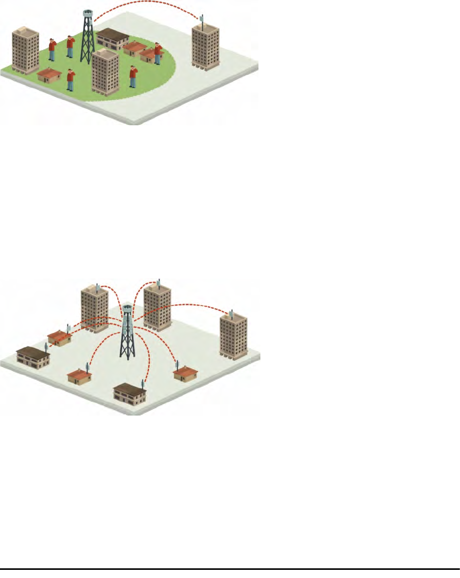
Key Applications Chapter 1
RADWIN 2000 User Manual Release 2.5.40 1-4
Key Applications
Cellular Backhaul
RADWIN 2000 products enable cellular carriers to expand their networks in both urban and
rural areas quickly and cost-effectively.
RADWIN 2000 and specifically RADWIN 2000 PDH systems are ideally suited for a broad
range of cellular backhaul deployment scenarios; they empower carriers to expand their pres-
ence into remote and low ARPU areas, provide enhanced overlay coverage in urban spots,
and can serve as a temporary or backup backhaul solution.
Figure 1-1: Typical Cellular Backhaul application
Broadband Access
With RADWIN 2000 solutions, service providers can expand their service footprint rapidly and
affordably, providing high-capacity services that match the ever-growing demand for high-
quality, high-speed broadband.
RADWIN 2000 is the ideal solution for last mile access, for large corporations requiring high
capacity either or both IP or TDM traffic.
Figure 1-2: Typical Broadband Access application

Mobility Applications Chapter 1
RADWIN 2000 User Manual Release 2.5.40 1-5
Figure 1-3: Typical WiFi Backhaul Application
Mobility Applications
RADWIN 2000 radios have been successfully deployed in a variety of Mobility Applications:
Border Control
RADWIN 2000 may be used in both towers and patrol vehicles to provide live video surveil-
lance. Handoff from tower to tower as the patrol vehicles moves along the patrol road is
seamless. The towers may be sited several kilometers apart (depending on topography) and
are themselves synchronized using RADWIN GSU.
Installation Security
Securing an installation like a factory or an airport is broadly similar to Border Control, how-
ever the distance are smaller and the towers may be connected to a control room using
cables.
Railway solutions
This is a relatively new application and includes for example,
»On-board surveillance
»On-board monitoring and control
»Passenger services including Internet access
For further information about Mobility Applications, contact RADWIN Customer Support.
Key Features of RADWIN 2000
Some of the outstanding features of the RADWIN 2000 radio series are as follows:
»E1/T1 + Ethernet in one Solution
RADWIN 2000 systems deliver carrier-class native E1/T1 + Ethernet in a single plat-
form, making them ideal for a range of backhaul and access applications. Up to 16 E1/
T1 services are supported for C, L and PDH models.
»High Capacity
The RADWIN 2000 system provides a high-capacity link of 100 Mbps net throughput
full duplex
»Superior Spectral Efficiency

Key Features of RADWIN 2000 Chapter 1
RADWIN 2000 User Manual Release 2.5.40 1-6
Built on advanced MIMO and OFDM technologies, the RADWIN 2000 system provides
a high-capacity link at channel bandwidths of 5, 10 and 20MHz. These channel
bandwidths supports high robustness of the air interface under interference and harsh
conditions.
»Multi-band Products
Every RADWIN 2000 Multi-band radio supports multiple frequency bands. For example
the RW-2050-0250 connectorized radio supports the bands: 5.9 GHz, 5.8 GHz, 5.4
GHz, 5.3 GHz, 4.9 GHz, 2.4 GHz and 3.4-3.7 GHz. The RADWIN 2000 Multi-band prod-
ucts support the regulations of FCC, IC Canada, ETSI and WPC India. DFS is sup-
ported where required by regulation.
»Advanced Air Interface
The RADWIN 2000 system provides an advanced air-interface based on MIMO,
antenna diversity and OFDM technologies, resulting in an exceptionally robust air
interface and high frequency band granularity.
Using the following technologies, the RADWIN 2000 air interface is designed to ensure
nonstop, high quality transmission, even under interference and harsh conditions:
• Automatic Adaptive Rate (AAR) is a mechanism that dynamically adapts the air
interface rate by changing both the signal modulation and coding.
• Automatic Channel Selection (ACS) chooses the best channel by monitoring the
available radio channels and dynamically selecting a channel which is best suited
for transmission at any given time.
• Automatic Repeat Request (ARQ) is a mechanism for error control during data
transmission. When the receiver detects an error in the received information, it
automatically requests the transmitter to resend the information. This process is
repeated until the transmission is error free or the error continues beyond a pre-
determined number of maximum transmissions. RADWIN 2000's ARQ mechanism
is optimized for time-critical traffic.
• Forward Error Correction (FEC) with very low overhead and algorithms specifi-
cally designed for the varying conditions of license-exempt frequency bands,
ensuring fast, robust and error-free communications.
»High transmission (Tx) power
The RADWIN 2000 system supports high Tx power, compliant with radio regulations.
High Tx power increases the system's availability and range, and enables the high
performance with smaller antennas, thus reducing the total cost of the solution (lower
CAPEX), installation and tower rent costs (lower OPEX).
The 5 GHz bands support a maximum Tx power of 25dBm whereas the 2.4 GHz band
supports a maximum Tx power of 26dBm.
»Superior range performance
The RADWIN 2000 system supports high capacity at superior ranges. The Link Budget
Calculator (Chapter 21) is used to determine the capacity and range according to the
choice of product, antenna, type of service and environmental conditions.
»HSS Interoperability between RADWIN 2000 and WinLink 1000
Site Synchronization is supported with any mix of RADWIN 2000 and WinLink 1000
links. RADWIN 2000 can be used to backhaul WinLink 1000 collocated links without
mutual interference

Key Features of RADWIN 2000 Chapter 1
RADWIN 2000 User Manual Release 2.5.40 1-7
»Monitored Hot Standby (1+1):
The RADWIN Monitored Hot Standby (MHS) protects up to sixteen E1/T1 services with
RADWIN 2000 and up to four E1/T1 services with WinLink 1000. It is designed to
provide high reliability high-capacity Point-to-Point Links. The RADWIN MHS
is
-
• Designed to provide redundancy and high reliability for carrier class operators
• Optimized for high capacity links operating in license-free bands
• A comprehensive solution providing protection against both equipment failure
and loss of air interface, by simple connectivity between a primary link and a sec-
ondary link
• Able to use a different band for maximum protection to the air interface
The main
features
of the RADWIN MHS are –
• Cut-over from the primary to the secondary link completely automatic
• Cut-over time no more than 50 ms
• Automatic restore to primary link as soon as it becomes available
• WinLink 1000 can backup a RADWIN 2000 link
A major
benefit
of RADWIN MHS is that is can underpin an affordable Service Level
Agreement structure by protecting part of the RADWIN 2000 trunks with WinLink
1000.
MHS supports TDM services; Ethernet services are carried by both links independently.
»Spectrum View
Spectrum View displays a visual representation of spectrum availability during the
link installation. It is an RF survey tool supporting the link installation prior to service
activation.
Use Spectrum View to assist you to choose the operating channel.
»Diversity
RADWIN 2000 links using dual bipolar antennas may be configured to transmit the
same data through both radios. This feature provides added data transmission integ-
rity under harsh conditions.
»Simple installation and management
RADWIN 2000 systems are extremely simple to install and maintain. They are typically
up and running in less than an hour.
The RADWIN Manager application has full local and remote management capabilities.
The user-friendly SNMP based management tool provides full end-to-end
configuration, event logging, and performance monitoring capabilities.
»Enhanced Security
The security features of RADWIN 2000 include:
• RADWIN 2000's AES 128-bit integrated advanced encryption support provides
enhanced air interface security for carriers and private networks. It ensures user
data protection with one of the most sophisticated commercially available com-
bined encryption and authentication techniques, CCM/AES. This technique com-
bines message authentication (preventing anti-spoofing and replay protection)
with commercial encryption, and complies with the IEEE 802.11i (phase iii) secu-
rity recommendations.

Components of a RADWIN 2000 Link Chapter 1
RADWIN 2000 User Manual Release 2.5.40 1-8
CCM/AES uses a symmetric 128-bit encryption key (EK), and a nonce, and pro-
vides both message encryption and authenticating signature. The nonce mecha-
nism enables the receiver to remember already received genuine messages and
reject all replayed messages.
• Initial encryption and authentication is based on a user-defined master key (Link
Password). While standard Wireless LAN encrypts only the Ethernet Payload, the
AES encrypts both the source and destination MAC addresses.
• In addition to normal log on access, Read or Write Community access is available
at log on
• Link Lock is a part of the RADWIN 2000 security concept. It is designed to dis-
courage physical theft of units and “piggybacking” using an otherwise identical
ODU to steal bandwidth or information. It locks a pair of synchronized ODUs for
mutually exclusive communication.
»SFP support in the IDU-C
Standard SFP modules are used, enabling any type of Ethernet physical connectivity
including various fiber connections. E3/T3 or E1/T1 over Ethernet SFPs can be used as
well.
»Separate management and traffic VLAN support
»Ethernet Ring Topology
»QoS Support (RADWIN 2000 C based links)
QoS enables Operator and Service Providers to offer delay-sensitive services such as
VoIP, IP-TV, time critical applications and online games.
Components of a RADWIN 2000 Link
The Outdoor Unit (ODU)
The Radio Outdoor Unit (ODU)
The ODU is the radio transceiver of the RADWIN 2000 system. It supports two antennas for
MIMO operation. It is available with an integrated antenna (
Integrated Antenna ODU
) or
with connectors for an external antenna (
Connectorized ODU
).
The ODU may be mounted on a pole or a wall, and connects to the IDU or PoE device using a
CAT5e cable.
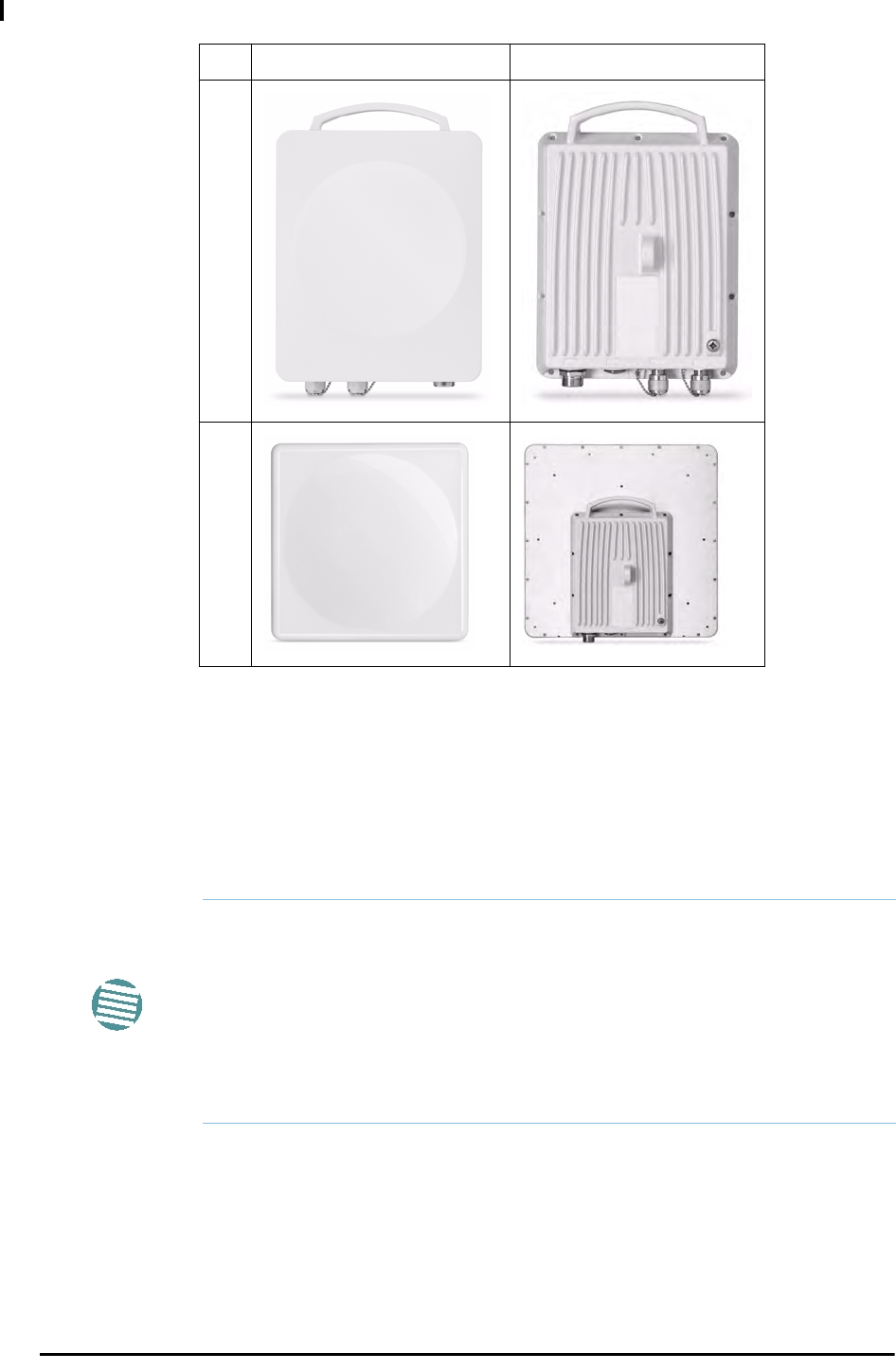
The Indoor Unit (IDU) Chapter 1
RADWIN 2000 User Manual Release 2.5.40 1-9
The ODU comes in two form factors as shown in Figure 1-4 below:
Figure 1-4: ODU Form Factors
• Integrated Antenna ODU
This ODU has an integrated 370mm (1.2ft) flat panel antenna. The ODU contains both
the radio and the antenna as a single unit housed in a weatherproof case.
• Connectorized ODU
This ODU has 2xN-type connectors for connecting an external antenna.
The Indoor Unit (IDU)
The IDU has the service ports and provides aggregation of these services towards the ODU
that transports them over the air. The IDU also provides power to the ODU.
Front Rear
ConnectorizedIntegrated Antenna
Note
See the RADWIN Product Catalog for the range of ODU products available
in release 2.5.40.
The external antenna choices are:
• Single bipolar antenna
• Two monopolar antennas
• Single monopolar antenna
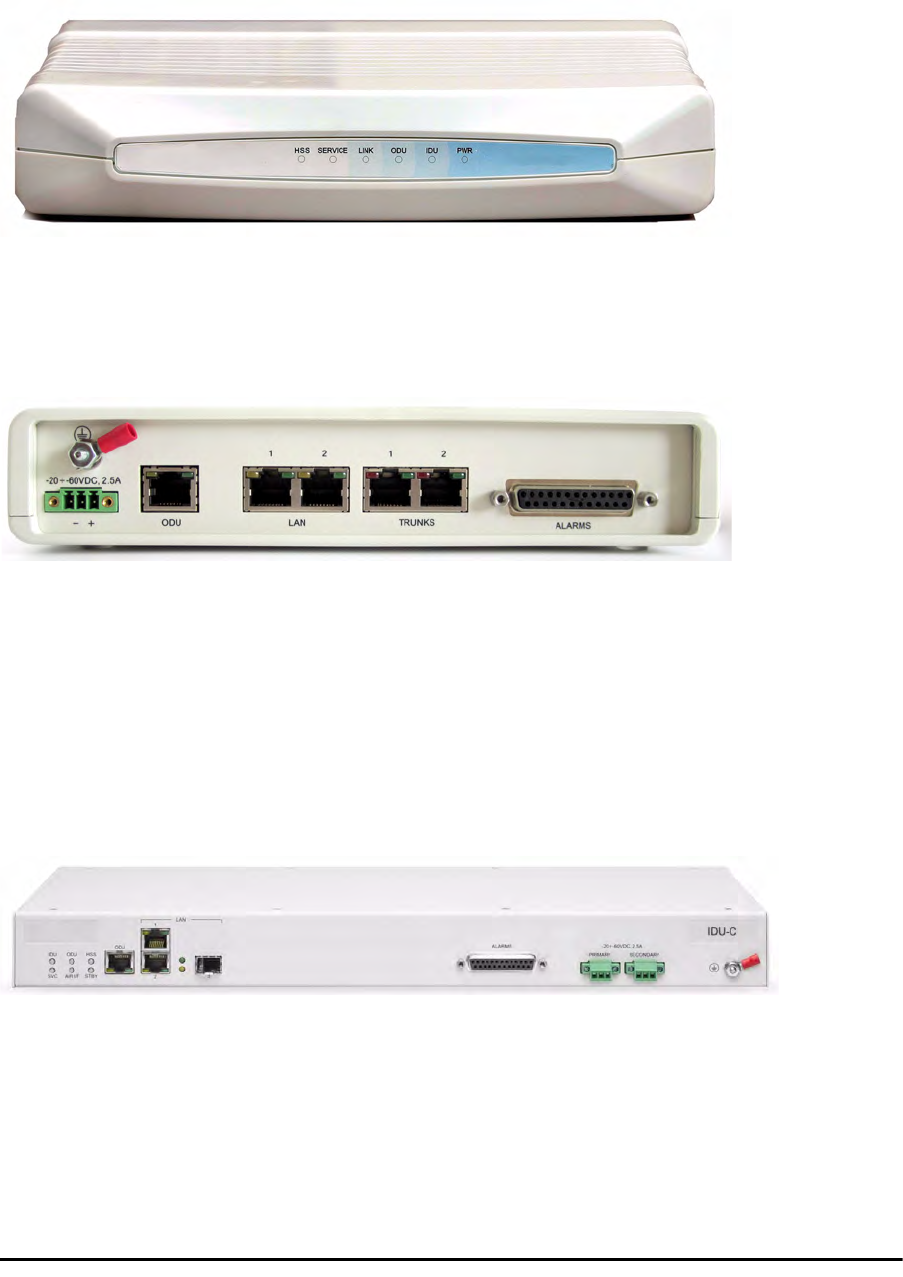
The Indoor Unit (IDU) Chapter 1
RADWIN 2000 User Manual Release 2.5.40 1-10
New style IDU-E for both WinLink 1000 and RADWIN 2000
The new style IDU-E is a carrier grade, compact, half 19 inch wide, 1U plastic unit, providing
up to two Ethernet ports and up to two E1/T1 interfaces. It offers Layer 2 support for Ether-
net service and HSS support for collocated links. It is a low cost unit intended for both Access
applications and Enterprise use.
Figure 1-5: New style IDU-E - front view (Note new HSS LED on the left)
The IDU-E rear panel (right to left) has a 25 pin Dry Contact Alarms port. the two (or no)
trunk ports, two LAN ports, an ODU port and finally a 3 pin DC power plug identical to that
used on the IDU-C.
.
Figure 1-6: New style IDU-E: Rear panel
IDU-C
The IDU-C is a carrier-class 19 inch, 1U unit, providing E1/T1 ports, Ethernet ports,
an SFP port, a STANDBY port for MHS control, dry contact alarms and indication
LEDs. It has two DC power feed connectors. An AC to DC converter is available for
powering the IDU-C from an AC source. The IDU-C is designed to be rack mounted.
Four IDU-C products are available in release 2.5.40 with 16, 8 and 4 E1/T1 ports and with
Ethernet only ports.
Figure 1-7: IDU-C, Ethernet only, front panel

Power Over Ethernet (PoE) Devices Chapter 1
RADWIN 2000 User Manual Release 2.5.40 1-11
Figure 1-8: IDU-C, 16 E1/T1 ports, front panel
Power Over Ethernet (PoE) Devices
Basic PoE Device
The basic PoE device provides Ethernet service only,
with power for the ODU. The PoE device is extremely
compact, having one Ethernet port, one ODU port and
a standard 3 pin male AC power socket.
It may be used with both WinLink 1000 and RADWIN
2000 radios.
Figure 1-9: Basic PoE device - showing the radio
Ethernet port
Outdoor (Ruggedized) DC PoE Device
This unit may be used with both WinLink 1000 and RADWIN
2000 radios.
Figure 1-10: Ruggedized DC-PoE Device: Input is -20 to -60 VDC (single input)
GSU
The GPS-based synchronization unit (GSU) is designed to handle inter-site interferences
under large-scale deployment scenarios.
The GSU is an outdoor unit consisting of a standard WinLink 1000 enclosure, a GPS antenna
and a PoE device.
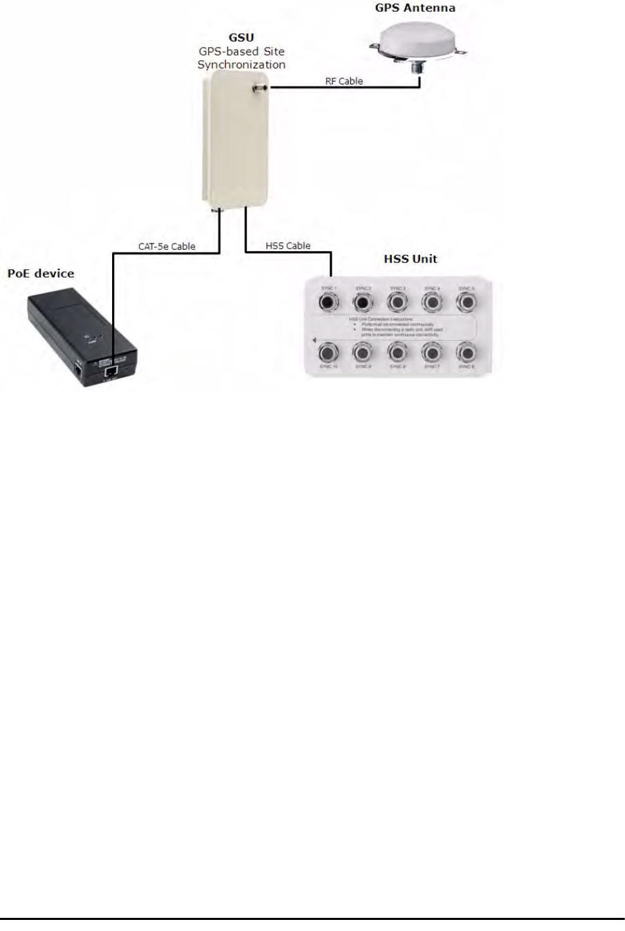
Antennas Chapter 1
RADWIN 2000 User Manual Release 2.5.40 1-12
The GSU is connected to the HSS Unit using a standard HSS cable. It synchronizes the trans-
mission timing of multiple Hub-Sites to the same clock source thus eliminating mutual inter-
ference (see Chapter 11).
Figure 1-11: General GSU configuration
Antennas
An antenna is the radiating and receiving element from which the radio signal, in the form of
RF power, is radiated to its surroundings and vice versa. The antenna gain and transmitting
power may be limited by country regulations.
The RADWIN 2000 may be operated with an integrated antenna that is part of the ODU unit,
or with external antennas connected to the ODU via N-type connectors. All cables and con-
nections must be connected correctly to reduce RF losses. The required antenna impedance
is 50Ω.
The 5.x GHz Integrated Antenna ODU is provided with 370 mm (1.2ft) flat panel antenna,
with a gain of 23dBi (5.x GHz) / 19dBi (4.9 GHz) and 8° beam width. The 2.x GHz Integrated
Antenna ODU is provided with 370 mm (1.2ft) flat panel antenna, with a gain of 16dBi and
16° beam width. The radio and the antenna are housed in a weatherproof case as a single
unit.

RADWIN Manager Chapter 1
RADWIN 2000 User Manual Release 2.5.40 1-13
Figure 1-12: ODU with integrated Flat Panel antenna
External antennas are available for the RADWIN 2000 radios, varying in operating frequen-
cies, form factor, size and gain, dual or single polarization.
The Flat Panel antenna shown below can be used either as an integrated or external antenna.
Figure 1-13: External Antennas for use with RADWIN 2000
See the RADWIN products catalog for RADWIN offering of external antennas. External anten-
nas are also available from third party antenna vendors.
RADWIN Manager
The RADWIN Manager is an SNMP-based management application which manages a com-
plete link over a single IP address. It can also manage each side of the link separately.
The RADWIN Manager application facilitates installation and configuration of the link between
the ODU units. The intuitive, easy-to-use RADWIN Manager has a graphical Microsoft Win-
dows interface, and can be run locally and remotely.
The RADWIN Manager provides:
• Installation Wizard
• Frequency band selection
• On-line monitoring of air interface quality allowing the administrator to monitor the
service and status of each link
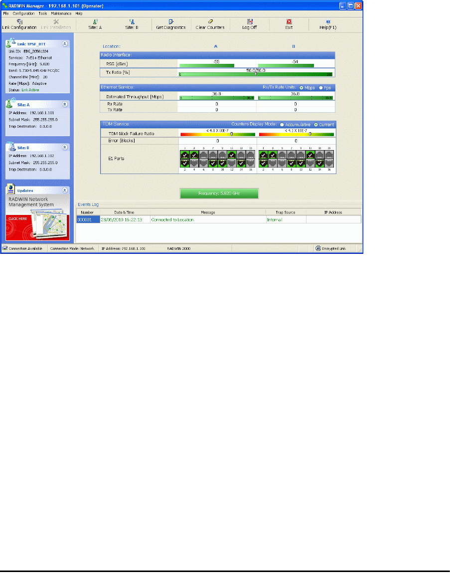
RADWIN Network Management System (RNMS) Chapter 1
RADWIN 2000 User Manual Release 2.5.40 1-14
• On-line monitoring of equipment alarms and QoS
• Local and remote loopback testing
• Configuration Wizard and site settings
• Integrated software upgrade utility
• On-line user manual and help files
• Link Budget Calculator for calculating the expected performance of the RADWIN 2000
wireless link and the possible service configurations for a specific link range.
The RADWIN Manager can easily be integrated with any SNMP based NMS system.
Figure 1-14: RADWIN Manager window
RADWIN Network Management System (RNMS)
The RADWIN Network Management System enables Service Providers to manage all RADWIN
links in their network from a Network Operations Center (NOC).
Using RNMS, Service Providers can configure and monitor up to 10,000 RADWIN links. The
intuitive easy-to-use RNMS provides a full range of network surveillance, monitoring, configu-
ration and fault management capabilities. It offers users complete visibility and control over
their RADWIN-based networks.
Accessories
RADWIN provides a variety of accessories to support the RADWIN 2000 system:
•PoE devices
• AC Power Adaptors
• External Lightning Protection Units
• Cables to connect the various system elements
• Grounding cables

Chapter 1
RADWIN 2000 User Manual Release 2.5.40 1-15
Documentation supplied with RADWIN 2000
The technical documentation supplied with a RADWIN 2000, is located on the product CD. It
includes the following items:
• A Quick Installation Guide for experienced installers (also hardcopy)
• A full User Manual - the document which you are reading
• A Help file accessible from the RADWIN Manager
• Link Budget Calculator
How to Use this Manual
This User Manual is divided into three functionally distinct sections reflecting the activities
required to set up a RADWIN 2000. The division is shown in the following table:
The Basic Installation section is divided into functionally distinct chapters reflecting the activi-
ties required to set up a RADWIN 2000. The division is shown in the following table:
Table 1-2: User Manual - General layout
Section General Content Purpose
1 Basic Installation Core information to install and operate a link
2 Advanced Installation Specialized installation techniques
3 Technical Information Background for advanced use
Table 1-3: User Manual layout
Chapter/
Appendix Subject Audience
2 Site Preparation Site survey team
3 Hardware Installation Field technician
4Getting Started with the
RADWIN Manager Installation technician
5 Installing the Link Installation technician
6The RADWIN Manager:
Main Window Installation technician, System manager
7 Configuring the Link Installation technician, System manager
8 Site Configuration Installation technician, System manager
9Monitoring and Diagnos-
tics Installation technician, System manager

A Little Terminology Chapter 1
RADWIN 2000 User Manual Release 2.5.40 1-16
A Little Terminology
In the field, a link typically has a local or headquarters site as for example in Figure 1-1
above. Here the service provider is the local or headquarters site. The service recipient is the
remote site.
Where the link is completely internal to a corporation, the choice of the local and remote is
just a matter of convenience.
A
link
then, consists of two
sites
.
In Broadband Wireless terminology, the local and remote sites are sometimes referred to as
“near” and “far”, “HQ” and “remote” and so on.
The site which is closer to the network core (often the local site) will be referred to as
site A
,
and the opposite side of the link, usually closer to the end user, as
site B
.
This choice is application-neutral and will be used throughout the manual both to describe the
sites and their names as in the examples.
The link is configured and managed using a PC, the
managing computer
connected to site
A. (The precise requirements for the managing computer are set out on page 4-1).
We will occasionally need to distinguish between the site to which the managing computer is
connected, and the second site, when they are not necessarily A or B. The former will be
called the
managing site
and the latter, the
over-the-air site
. Which is which, is always
determined by the location of the managing computer.
RADWIN 2000 supports three connection methods for the managing computer:
•
Local
- a direct peer to peer connection between the Ethernet ports on the managing
computer and the IDU or PoE device. Local connection is always read-write.
•
Network
- the managing computer and the site A IDU or PoE device belong to a LAN
and communicate through a router or switch
•
Over-the-air
- the managing computer connects to site B via the air interface
• The managing computer may be connected to the link through an IDU or a PoE
device. In what follows, where ever we refer to an IDU it includes PoE devices unless
stated otherwise. Typically, if we need to refer to an IDU as such, we will use a model
name such as IDU-C.
The terms uplink and downlink, originate from the field of Satellite communications. In a
backhaul or ISP context, uplink is from the user to the network and downlink is from the
network to the user.

Conventions Used in this Manual Chapter 1
RADWIN 2000 User Manual Release 2.5.40 1-17
Conventions Used in this Manual
Notifications
Notifications consist of Notes, Cautions and Warnings.
Typographical conventions
General
Where a term is defined or introduced for the first time, it is shown in Boldface. You will have
noticed this usage in the Terminology section above.
Software
The RADWIN Manager is a Microsoft Windows application following the user interface con-
ventions of familiar Microsoft Windows programs.
We would describe the chain of menu commands indicated in the navigation example of
Figure 1-15 like this,
Tools|Active Alarms|1 A
using Boldface for the menu labels and vertical bars to separate them.
Note
The purpose of a Note is to
• Draw your attention to something that may not be obvious or coun-
ter-intuitive
• Emphasize a special feature or peculiarity of the RADWIN 2000
• Offer an external reference for additional information
• Add a caveat that would not qualify as a full Caution or Warning (see
below)
• Provide additional background to what follows
• Offer a recommendation
• Highlight an indication of something to watch out for
• Advise you if an action has “side effects” i.e. it may disturb something
else that would be best left undisturbed
• Remind you of something that should be kept in mind
Caution
A Caution is a notification of risk of damage to equipment or of service
degradation
Warning
A Warning is a notification of risk of danger to persons operating near the
equipment

Windows Terminology Chapter 1
RADWIN 2000 User Manual Release 2.5.40 1-18
Figure 1-15: Menu navigation in the RADWIN Manager
Similarly, mouse click items will be referred to like this:
“Click Next to continue.”
(A mouse click always uses the left mouse button unless stated otherwise.)
Windows Terminology
Look at Figure 1-1 above. The main application display which you see consists of a frame-
window with a menu bar, system icons and content. It will be referred to as a window, the
main window or the Manager window depending on context.
The top line of icons is the tool bar, and provides part of the menu bar functionality with a
mouse click.
At the bottom of the window is the status bar, a line of icons and text boxes.
The central part of the main window consists of several panes: On the right, there are Radio
Interference, Ethernet Service and the Frequency panes. The left hand pane (with the blue
background) is split into three sub-panes.
If you click Site A or Site B in the tool bar, you will be offered another window, which in turn
displays on of several panels depending on which function you choose.

Viewing and Printing Chapter 1
RADWIN 2000 User Manual Release 2.5.40 1-19
Figure 1-16: Site Configuration window with open Management panel
Viewing and Printing
This manual is optimized for viewing online as a PDF file. To this end it uses an 11 point
Tahoma typeface for main text. Tables for most part, use 7 or 8 point fonts. Here are a few
pointers for hard-copy printing:
• The text and table typefaces used are large enough to print the manual at two pages
per sheet
• For good legibility, use a commercial grade laser printer. A color printer is of course
best, however a monochrome printer set to use gray-scale gives acceptable results
• Better quality inkjet printers also give good output

RADWIN 2000 User Manual Release 2.5.40 2-1
Chapter 2
Site Preparation
Planning the Link Site
Overview
Link site planning consists of a set of surveys, which must be carried out before any equip-
ment is brought to the site. If for some reason, the outcome of any of these surveys is nega-
tive, site re-location will need to be considered.
A Site Survey consists of three stages:
1. Preliminary survey - The proposed link is analyzed in the office using a topographic map.
2. Physical survey - The locations of the indoor and outdoor equipment are determined on-
site.
3. Radio Frequency (RF) survey - It is recommended that the installation area be scanned
with a spectrum analyzer, to identify RF interference so as to determine a clear channel for
radio installation (on-site).
The Site Survey
Introduction
RADWIN wireless links must be planned before installation. The designated installation site
must be appraised to determine that the wireless system is able to operate efficiently and
provide connectivity without signal degradation.
RADWIN 2000 offers a wide operating frequency range. A free frequency channel must be
determined within the operating range, for optimum performance.
Recommended Equipment
Stage 1: Preliminary Survey
• Topological map of the area
• Urban map of the area
•Compass
Stage 2: Physical Survey
• 100 meter tape measure

Stage 1: Preliminary Survey Chapter 2
RADWIN 2000 User Manual Release 2.5.40 2-2
• Ohmmeter, to check ground connection
•Binoculars
•Map
• Digital camera
• Paper, pencil, and a clipboard
• GPS device (optional)
• Compass (optional)
Stage 3: RF Survey
• Spectrum Analyzer with Max Hold function and screen capture facility that can store
multiple images, for documentation purposes
• RF accessories (connectors and cables)
• Communication devices (for example, cellular phones, or a set of walkie-talkies)
Stage 1: Preliminary Survey
A preliminary survey is necessary before visiting potential installation sites. As much detail as
possible should be obtained about the two designated ODU installation sites and the area
between them.
To perform a preliminary survey:
1. Mark the two designated installation sites on a topographic map of the area.
2. Measure the distance between the sites; check that it is within the specified range of
the equipment.
3. On the urban map, check for developed areas situated between the two installation
sites. Pay attention to these areas when performing the physical site survey; there
may be tall buildings, RF towers, or transmitters, which could cause interference to
the link.
4. Check the area between the two sites for obstructions such as:
• High ground - hills or mountains
• Lakes or large bodies of water. Water has a reflection effect on RF signals like a build-
ing. This type of reflection causes the received amplitude to be reduced. As a rule of
thumb, the presence of a large body of water between the link sites may double the
required antenna height.
5. Determine and record the compass bearings between both ODUs, relative to north.
6. If there are obstructions between the two sites, calculate the Fresnel Zone (see
Chapter 21 for details).
7. If the site chosen does not meet requirements, consider alternative sites.
8. Use the Link Budget Calculator (on the CD supplied with the equipment or using the
RADWIN Manager) to determine the expected performance.

Stage 2: Physical Survey Chapter 2
RADWIN 2000 User Manual Release 2.5.40 2-3
Stage 2: Physical Survey
The physical site survey reviews the environment of the proposed installation location, to
ensure that the link sites are suitable for the wireless network. The results of the physical site
survey should be recorded.
To perform a physical survey:
1. From the compass readings taken in the preliminary survey, find the azimuth (hori-
zontal position) that the ODU should face towards the second ODU.
2. Using binoculars, locate any obstructions such as tall trees, high buildings, hills or
mountains. Look for other RF towers between the two sites. Mark the locations of
the obstructions on the map.
3. Determine the location for the ODU (having regard for existing rooftop installations
and tower space). It should be above any obstructions, considering the Fresnel zone
(see Chapter 21).
4. If you need to install the ODU on a tower, make sure that the tower is far away from
overhead electric power lines.
5. Determine a location for the indoor equipment; it should be as close as possible to
the ODU. At an existing site, there is probably an equipment room with cable-routing
channels.
6. Measure and record the path length of the cable from the ODU position to the indoor
equipment room.
7. Determine the ground and lightning connection points of the installation. The ODU
and IDU must both be grounded.
8. Using the Ohmmeter, measure and record the resistance of the required installation
to the grounding point. The resistance must be less than 1O ohm.
9. Review the results of the physical site survey. Decide if the site is suitable for the
wireless network installation.
• If the site is suitable, continue with stage 3, the RF survey
• If the site is not suitable, survey another site
Additional Outdoor Site Requirements
The ambient outdoor operating temperature should be -35 to 60C (-31 to 140F).
Additional Indoor Site Requirements
The following requirements guarantee proper operation of the system:
Note
It is advisable to go on a clear day, so you can more easily see any
obstructions between the two sites.
Note
The IDU - ODU cable length limit is 100m, in accordance with IEEE 10/
100BaseT standards.

Stage 3: RF Survey Chapter 2
RADWIN 2000 User Manual Release 2.5.40 2-4
• For IDU-C units, allow at least 90 cm (36 “) of front clearance for operating and main-
tenance accessibility. Allow at least 10 cm (4 “) clearance at the rear of the unit for
signal lines and interface cables
• The ambient operating temperature should be 0 to 50°C (32 to 122 °F) at a humidity
of up to 90%, non condensing
Stage 3: RF Survey
The RF survey examines the wireless environment of the installation site, to determine
whether there are available channels within the radio operating frequency band. An RF survey
is performed using a spectrum analyzer.
It is advisable to familiarize yourself with the spectrum analyzer before going out on site, spe-
cifically the Max Hold and Marker functions.
You should perform the RF survey at both proposed link sites.
The survey should be carried out during a busy time of day, to best judge the worst-case
radio interference. Allow 2-4 hours duration for a good RF survey.
RF Planning for Dense Installations and Collocated Sites
Interference may arise from
• Self interference from collocated RADWIN radios
• Other collocated radio devices installed on the same site.
To avoid or minimize interference, follow these recommendations:
• For collocated RADWIN units, use an HSS unit to synchronize between them. Select a
different operating channels for each collocated RADWIN unit.
• If one or more collocated units are not RADWIN units, ensure that there is a physical
separation of at least three meters between a RADWIN unit and any other collocated
radio on the site.
• Use the largest possible frequency gap between these units.
• Choose the best frequency channel (as clear as possible form interference). You may
change band with “Combo” WinLink 1000 products and all RADWIN 2000 products).
• To select a frequency channel, move the link to Installation Mode (using Site con-
figuration) and start the Installation wizard. In the Channel Settings window, use
the quality bar at the bottom to help you choose a better channel (clearer of interfer-
ence).
• If you are using WinLink 1000 radios, install the collocated links with different antenna
polarizations.
• If you are using the RADWIN 2000 radios, use the Spectrum View tool to find the
best working channel (Tools | Spectrum View).
Note
It is possible to install the link and use the RADWIN Manager to find a clear
channel. Each frequency channel can be evaluated in turn. Achievement of a
clear channel is indicated by the marker in the Quality bar on the Channel
Setting window (see Figure 5-6) moving into the green area.

RF Planning for Dense Installations and Collocated Sites Chapter 2
RADWIN 2000 User Manual Release 2.5.40 2-5
• Decreasing the Tx Power of a link will reduce collocation interference (Site Configu-
ration | Air Interface).
Note
Use the Link Budget Calculator to determine the minimum Tx Power
required to maintain link stability.
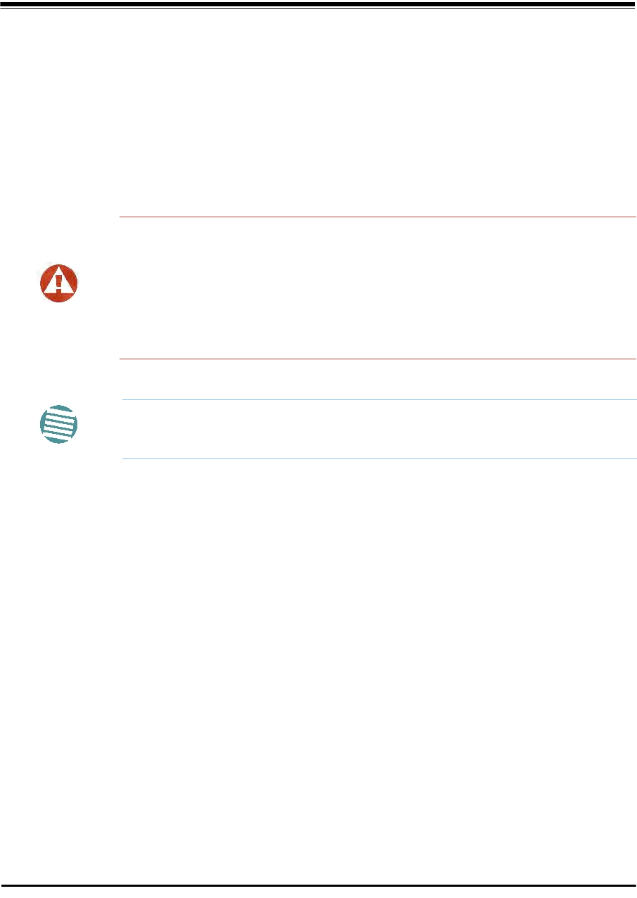
RADWIN 2000 User Manual Release 2.5.40 3-1
Chapter 3
Hardware Installation
This chapter sets out the requirements and procedures for the hardware installation and
alignment of a RADWIN 2000 link in accordance with the prior planning as set out in Chapter
2. It is intended to guide qualified field technicians.
Safety Practices
Preventing overexposure to RF energy
To protect against overexposure to RF energy, install the ODUs so as to provide and maintain
minimal separation distances from all persons.
When the system is operational, avoid standing directly in front of the antenna. Strong RF
fields are present when the transmitter is on. The ODU must not be deployed in a location
where it is possible for people to stand or walk inadvertently in front of the antenna.
Grounding
All RADWIN products should be grounded during operation. In addition:
•The ODU should be earthed by a wire with diameter of at least 12AWG.
The RADWIN 2000 ODU must be properly grounded to protect against lightning. It is
the user's responsibility to install the equipment in accordance with Section 810 of the
National Electric Code, ANSI/NFPA No.70-1984 or Section 54 of the Canadian
Electrical Code. These codes describe correct installation procedures for grounding the
Warning
Outdoor units and antennas should be installed ONLY by experienced
installation professionals who are familiar with local building and safety
codes and, wherever applicable, are licensed by the appropriate
government regulatory authorities. Failure to do so may expose the end
user or the service provider to legal and financial liabilities. RADWIN and its
resellers or distributors are not liable for injury, damage or violation of
regulations associated with the installation of outdoor units or antennas.
Note
The material in this chapter is generic to all RADWIN radio link products
unless stated otherwise.

Protection against Lightning Chapter 3
RADWIN 2000 User Manual Release 2.5.40 3-2
outdoor unit, mast, lead-in wire and discharge unit. It also lays down the size of
grounding conductors and connection requirements for grounding electrodes.
The RADWIN 2000 ODU must be grounded to a Protective Earth as described in
Chapter 18 and in accordance with the Local Electrical Regulations.
• The earth lug on the IDU-C should be connected to the protective earth at all times,
by a wire with a diameter of 18 AWG or wider. Rack-mounted equipment should be
mounted only in earthed racks and cabinets.
Further, you should -
• Always make the ground connection first and disconnect it last
• Never connect telecommunication cables to ungrounded equipment
• Ensure that all other cables are disconnected before disconnecting the ground
More detailed guidelines are supplied in Chapter 18.
Protection against Lightning
The use of lightning protection is dependent on regulatory and end user requirements. All of
RADWIN outdoor units are designed with surge limiting circuits to minimize the risk of dam-
age due to lightning strikes. RADWIN recommends the use of additional surge arrestor
devices to protect the equipment from nearby lightning strikes.
See Chapter 18 for detailed installation instructions of lightning protection devices.
General
• It is recommended that installation of the outdoor unit be contracted to a professional
installer.
• Before working on equipment connected to power lines or telecommunication lines,
you should remove jewelry or any other metallic object that may come into contact
with energized parts.
• Use extreme care when installing antennas near power lines.
• Use extreme care when working at heights.
• When using an AC power source for RADWIN 2000 always use the AC power adapter
supplied by RADWIN.
• Use the right tools. In addition to standard tools required for any kind of ODU or
antenna installation, RADWIN 2000 requires additional specific tools detailed on
page 3-5 below.
Package Contents
The RADWIN 2000 packages include the following items:
ODU Package Contents
The ODU package contains:
• One ODU - see Figure 3-2 and Figure 3-3 below for front and rear view
• An ODU mounting kit - see Figure 3-1 below
• A CD containing -
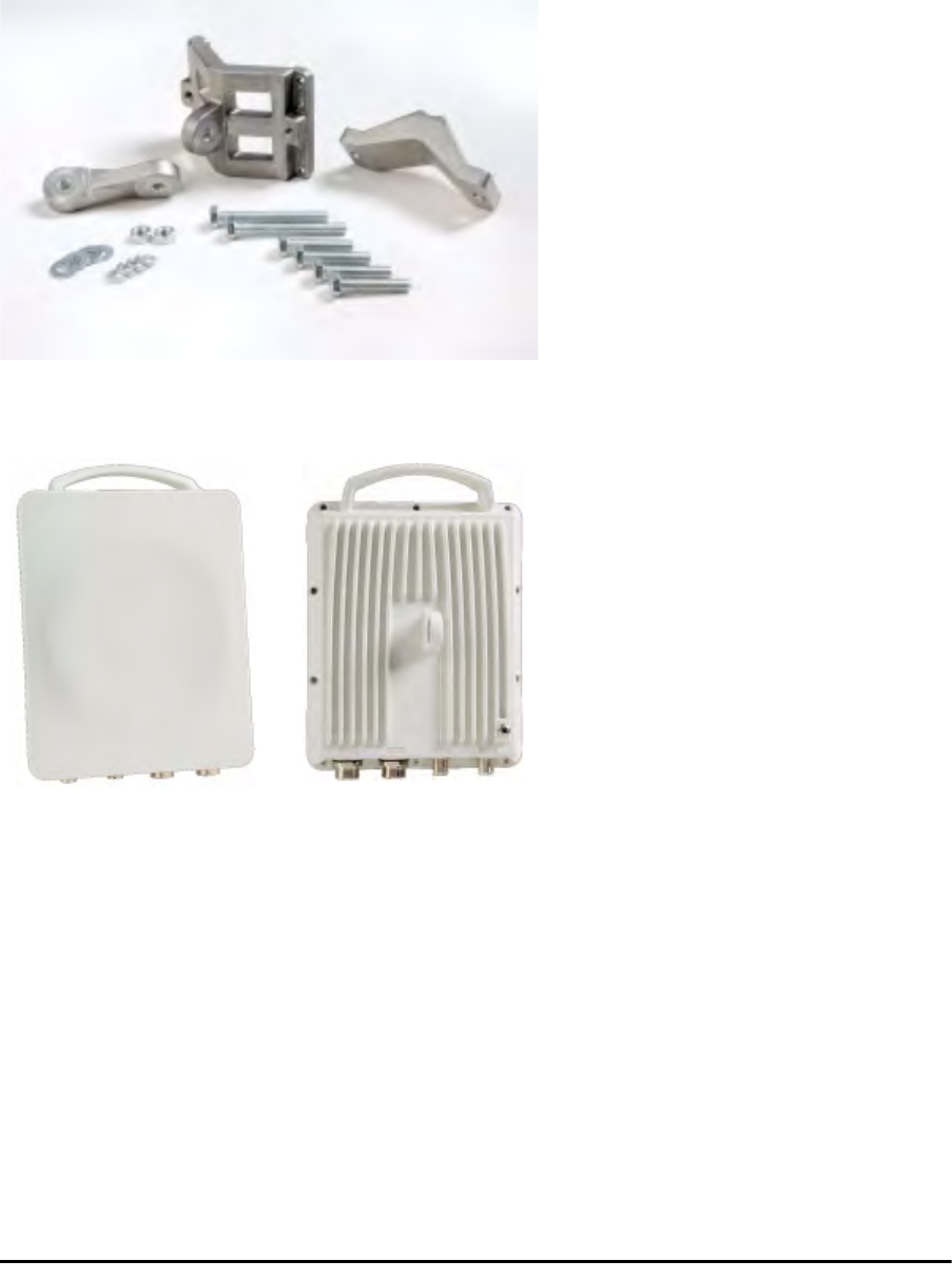
ODU Package Contents Chapter 3
RADWIN 2000 User Manual Release 2.5.40 3-3
• the RADWIN Manager
•Quick Start Guide
• User Manual - the document you are reading
• Link Budget Calculator
• Label showing the MAC address and the alternative Community string. The label is
self-adhesive. You should keep this label safe
• Cable glands (to be used with the ODU-IDU cable)
Figure 3-1: ODU Mounting kit
Figure 3-2: Connectorized ODU - Front and rear views
ODU - Front View ODU - Rear View
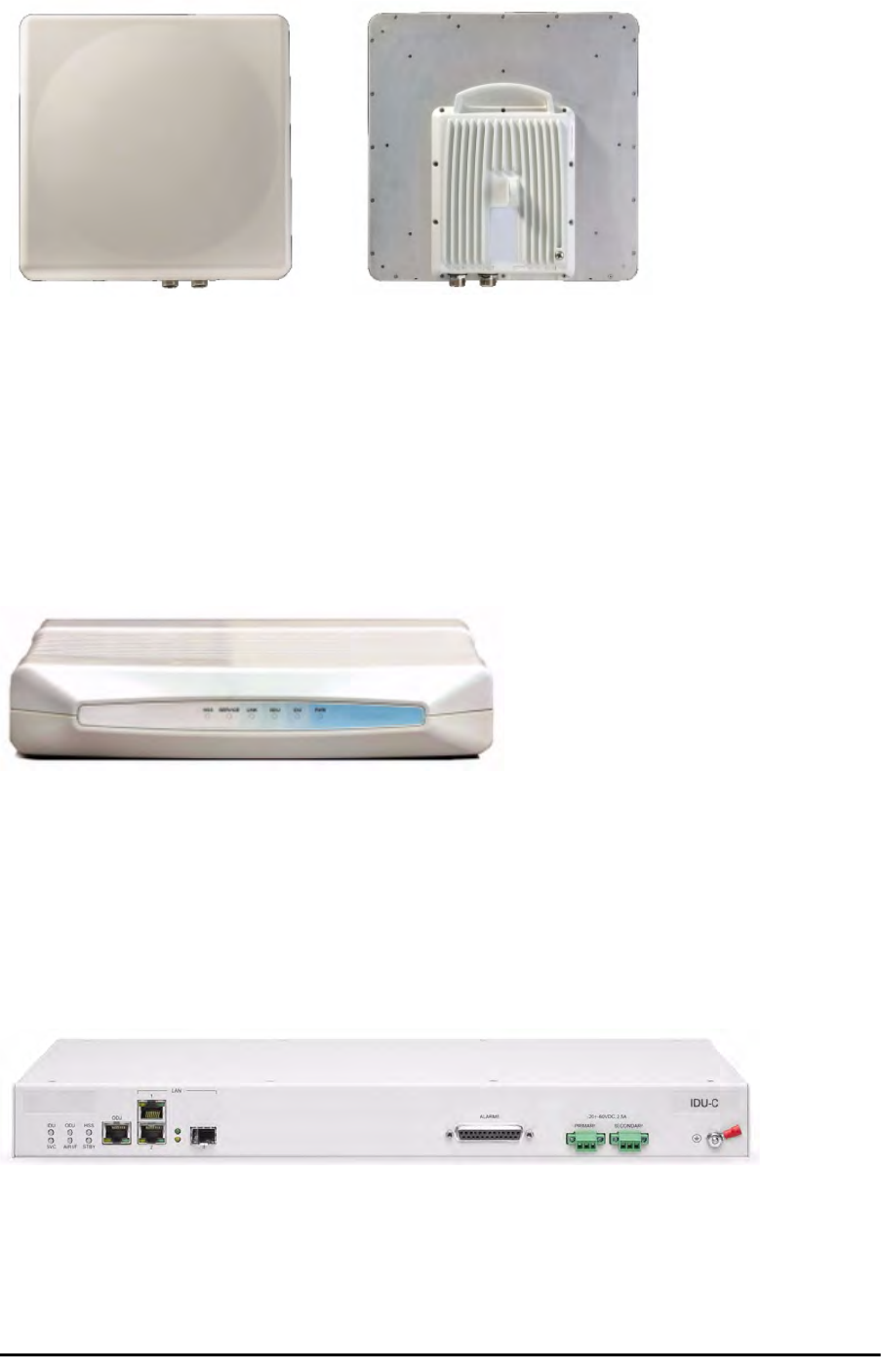
IDU-E package containing: Chapter 3
RADWIN 2000 User Manual Release 2.5.40 3-4
Figure 3-3: Integrated ODU - Front and rear views
IDU-E package containing:
•IDU-E
• AC/DC Converter
• IDU-E wall-mounting drilling template
• Self adhesive label showing the IDU LED operation
Figure 3-4: IDU-E- front view
IDU-C Package Contents
The IDU-C package contains:
• IDU-C - see Figure 3-5 below.
• 19” rack mounting kit - see Figure 3-7 below
• Two DC power plugs for power cables - see Figure 3-7 below
Figure 3-5: IDU-C Package contents - the IDU-C, Ethernet only
ODU - Front View ODU - Rear View

External Antenna Package Contents Chapter 3
RADWIN 2000 User Manual Release 2.5.40 3-5
Figure 3-6: IDU-C Package contents - the IDU-C, 16 E1/T1 ports
Figure 3-7: IDU-C Package contents - the mounting kit and DC power plugs
External Antenna Package Contents
• Antenna
• RF cable 1m (3’) long; two cables supplied with bipolar antennas, single cable sup-
plied with monopolar antennas
• Mounting kit
Additional Tools and Materials Required
The following is a list of the equipment and materials required to install RADWIN 2000 hard-
ware.
Tools and Materials
• Crimping tool for RJ-45 (if the ODU-IDU cable is without connectors)
• Spanner/wrench 13 mm (½”)
• Drill (for wall mounting only)
•Cable ties
• Sealing material
Cables and connectors
• ODU grounding cable 12AWG
• IDU grounding cable 18AWG
• ODU-IDU cable (outdoor class, CAT-5e, 4 twisted pairs, 24AWG)
• For PoE based links: A crossed Ethernet LAN cable
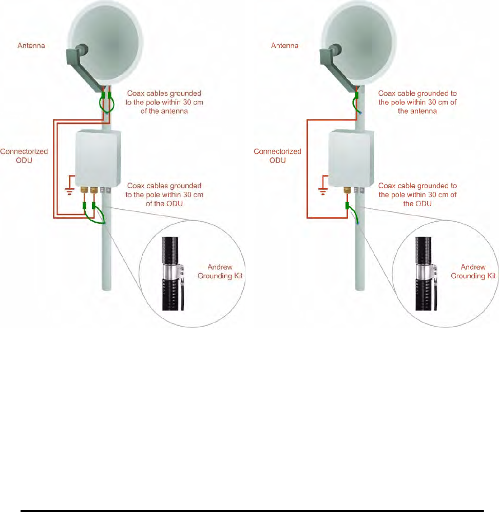
Hardware Installation Sequence Chapter 3
RADWIN 2000 User Manual Release 2.5.40 3-6
Hardware Installation Sequence
The following steps are required to install the RADWIN 2000 system:
1. Mounting the ODUs, page page 3-7.
2. Mounting the external antennas (if used), page page 3-7.
3. Mounting the Lightning Protection devices (if used), page page 3-8.
4. Outdoor connections, page page 3-8.
5. Mounting the IDUs, page page 3-9.
6. Indoor connections, page page 3-12.
7. Aligning the ODUs/antennas, page page 3-13.
See Figure 3-8 below, which illustrates a typical installation of a RADWIN 2000 or a WinLink
1000 with external antenna(s).
Figure 3-8: Typical Installation (with external antenna) Left: RADWIN 2000 Right: WinLink
1000
The installation steps are detailed in the following sections.

Outdoor installation Chapter 3
RADWIN 2000 User Manual Release 2.5.40 3-7
Outdoor installation
Preparing the ODU before Deployment
Each ODU must be pre-loaded with an IP address. This may be done prior to deployment in
the field, or on-site using a Laptop computer. The process is quite straight-forward and
described in Chapter 19.
Mounting the ODU
The ODU can be mounted on a pole or a wall. In both installations, the supplied mounting kit
is used to secure the ODU.
A RADWIN 2000 link operates in pairs of two ODUs with the same configuration. Both ODUs
must be installed, and the antennas aligned for maximum throughput.
To mount the ODU on a pole or a wall:
1. Ensure that the ODU is properly grounded.
2. Mount the ODU onto the pole or wall. Ensure that the unit is oriented so that the
cable connectors are at the bottom. (If they are on top, water may penetrate
into the unit causing damage.) It is possible to mount an ODU horizontally. See
Chapter 17 for details.
3. Refer also to Chapter 17 for detailed ODU mounting kit contents and schematics.
Mounting external antennas
If you are using ODU with an integrated antenna, skip to Mounting the Lightning Protec-
tion Devices below.
The supplied mounting kit is used to mount the antenna onto a pole. The antennas must be
aligned for maximum throughput.
Note
A mast-sited ODU typically uses a pole attached to the mast.
Warning
Prior to connecting cables to the ODU, the protective earth terminal (screw)
of the ODU must be connected to an external protective ground conductor
or to a grounded pole.
• Only a qualified person using the proper safety equipment should
climb the antenna mast
• Only qualified professional personnel should install or dismantle
ODUs and masts
Note
• Do not tighten the ODU to its mounting brackets until the alignment
process of the antenna is complete.
• Ensure that there are no direct obstructions in front of the ODU or
interference from man-made obstacles.

Mounting the Lightning Protection Devices Chapter 3
RADWIN 2000 User Manual Release 2.5.40 3-8
To mount an external antenna:
1. To mount an external antenna, ensure that the antenna is properly grounded and
then mount the antenna onto the pole. Refer to Chapter 17 for detailed antenna
mounting instructions.
2. Follow the mounting instructions supplied with the antenna.
Mounting the Lightning Protection Devices
The use of lightning protection is dependent on regulatory and end user requirements. The
RADWIN 2000 ODU is designed with surge limiting circuits to minimize the risk of damage
due to lightning strikes. RADWIN recommends the use of additional surge arrestor devices to
protect the equipment from nearby lightning strikes.
Refer to Chapter 18 for detailed installation instructions of lightning protection devices.
Outdoor Connections
To complete the outdoor connections:
1. Connect the ground cable to the ODU chassis as marked on the ODU.
2. Connect the antenna cable(s) to the ODU.
3. Connect the lightning protection device to the ODU (see Chapter 18).
4. Attach the ODU-IDU cable to the ODU RJ-45 connector (see Appendix B for the
connector pinout)
5. Screw in the cable glands to ensure hermetic sealing of the ODU.
6. Secure the cables to the pole, mast or brackets using UV-rated cable ties.
Indoor Installation
Installing IDU-E
IDU-E Installation
The IDU-E can be wall mounted, placed on a desktop or take up one half of a 1U rack slot.
The unit should be grounded, cabled to the ODU and connected to power using the supplied
AC/DC adapter.
.
Figure 3-9: New style IDU-E: Rear panel
Warning
Do not stand in front of a live antenna.
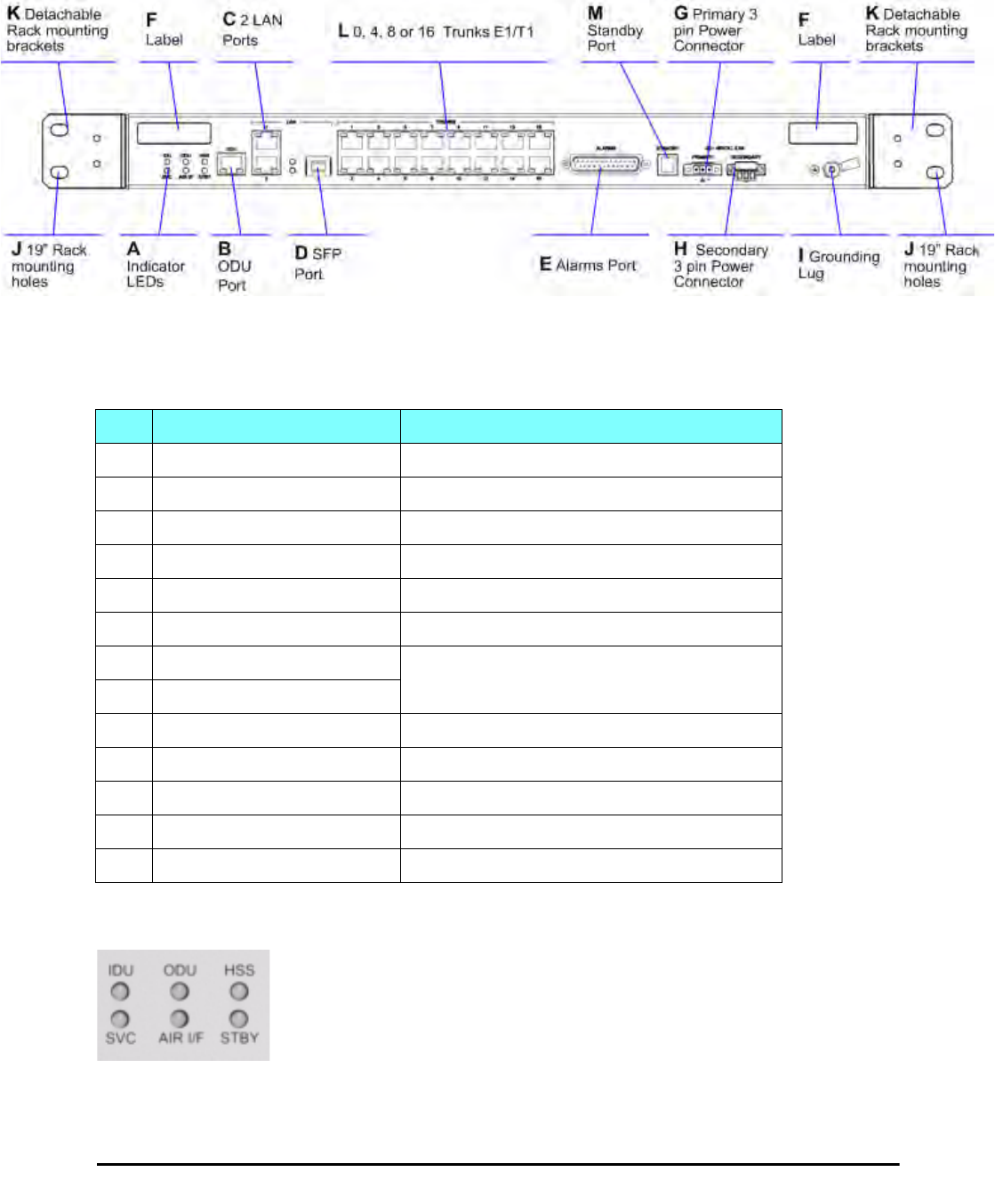
Mounting the IDU-C Chapter 3
RADWIN 2000 User Manual Release 2.5.40 3-9
Mounting the IDU-C
IDU-Cs are all rack mountable, as shown in Figure 3-10. A front panel keyed schematic of a
rack mounted IDU-C is shown in the figure below.
Figure 3-10: IDU-C front panel
Further description of the keyed items in Figure 3-10 is shown in Table 3-1 below:
The Indicator LEDs (Item A in Table 3-1 above) are shown in more detail below:
Figure 3-11: IDU-C Front Panel LEDs
The IDU-E Front Panel LEDS look like this and are functionally the same as the IDU-C LEDs.
Table 3-1: Components of an IDU-C front panel
Key Label Remarks
AIndicator LEDs See Figure 3-11.
BODU Port RJ-45 connector, see Table B-1.
CLAN RJ45Ports Ethernet, RJ-45 connector, see Table B-3.
DLAN SFP Port See Appendix C.
EAlarm Ports Standard DB25 female connector, see Table B-7.
FLabel indent Place for adhesive identification labels.
GPrimary 3 pin Power Connector Standard 3 pins in line power connector, see Table B-8.
HSecondary 3 pin Power Connector
IGrounding Lug Use the lug supplied.
JRack mounting holes
KDetachable Rack mounting brackets
L0, 4, 8 or 16 E1/T1 Ports See Table B-5.
MStandby Port Hot Standby ready: HSB cable socket, see Table B-6.

Mounting the IDU-C Chapter 3
RADWIN 2000 User Manual Release 2.5.40 3-10
Figure 3-12: IDU-E Front Panel LEDs
The purpose of the LEDs is shown in Table 3-2 below:
Table 3-2: IDU-C Front Panel LEDs
Name Color Function
IDU
Green
Blinking Green
Red
Blinking Orange
IDU operational
During power-up only
Failure
During power-up; continues if ODU fails to load IDU firmware.
Also, when using an IDU-C to replace a PoE device in which case all other LEDs off.
ODU Green
Red ODU-to-IDU communication link is operating
ODU-to-IDU communication link is disrupted
AIR I/F Green
Orange
Red
Wireless link is synchronized
During installation mode; also signals software mismatch on some identical ODUs
Wireless link lost synchronization
SVC
Green
Orange
Blinking Orange
Red
Off
E1 or T1 line is synchronized
Alarm detected at the opposite site interface; Normal or LOSS
Local or remote loopback
Alarm detected at this site interface
Ethernet only IDU or E1/T1 not configured
HSS See supplementary Table 3-3 following.
STBY
Hot Standby Mode - for use with
Trunks only Link State
Green
Blinking Green
Red
Orange
Off
Primary
Secondary
Primary
Secondary
Off
Active
Not active
Not active
Active
HSM not activated
Hot Standby Mode - For use with
Ethernet only in a 1+1 Ring
application) Link State
Green
Blinking Green
Red
Orange
Off
Hardware ready
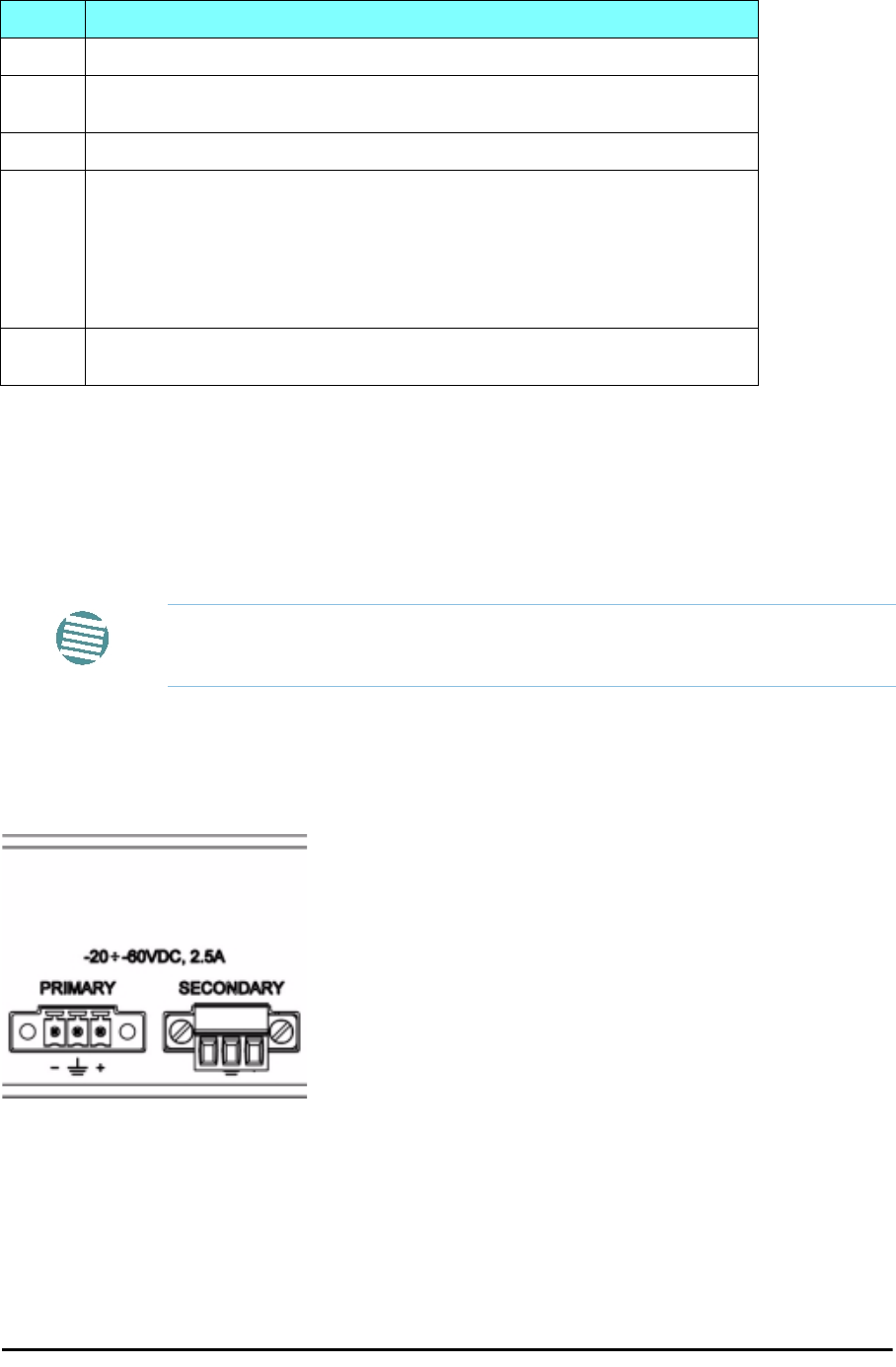
Connecting power to the IDU Chapter 3
RADWIN 2000 User Manual Release 2.5.40 3-11
To mount an IDU-C:
1. Attach the rack mounting brackets (K) to the IDU.
2. Bolt the IDU into an empty slot in the rack, ensuring that it sits securely.
3. Ground the IDU to the rack using grounding lug I. The IDU should be left perma-
nently grounded.
Connecting power to the IDU
The IDU-C has redundant power connection circuits (items G and H in Figure 3-10 above).
An enlarged schematic of the power connectors is shown in below:
Figure 3-13: IDU-C Power connectors
The connectors are 3 pin in line female, with polarities (left to right) minus, ground, plus. To
avoid damage to the IDU, always use an AC/DC adapter supplied by RADWIN.
Ensure that the IDUs at both sites are powered up.
The IDU-E has a single three pin power connector, the same as used on the IDU-C.
Table 3-3: IDU-C and New Style IDU-E Front Panel LEDs for HSS
Color Function
Green This ODU is HSS master, generating signal, and HSS Sync is OK
Blinking
Green This ODU is a HSS client and in Sync
Red HSS not operational due to improper signal detection. This ODU is not transmitting
Orange
HSS is operational. One of the following conditions apply:
• This ODU is a master that is generating signals and detecting signals
• This ODU is a master that is generating signals but detected improper signals
• This ODU is a client “Continue Tx” but is not detecting signals
• This ODU is a client “Disable Tx” and is detecting signals from multiple sources
All orange cases transmit.
Off HSS is not activated
Disconnection between ODU and IDU
Note
Instead of using the rack mounting brackets, the IDU may be rail mounted
using the four screw holes on each of its sides.

Connecting the ODU to the IDU Chapter 3
RADWIN 2000 User Manual Release 2.5.40 3-12
Connecting the ODU to the IDU
The ODU-IDU cable conducts all the user traffic between the IDU and the ODU, and also pro-
vides power to the ODU. The maximum length of the ODU-IDU cable is 100m (328ft) in
accordance with 10/100BaseT standards.
The ODU-IDU cable is supplied pre-assembled with RJ-45 connectors, at the length specified
when ordering, or as a cable drum with spare connectors. If the ODU-IDU cable was not
ordered, use an outdoor class, CAT-5e 24AWG shielded cable. See Appendix B for Wiring
Specifications.
To connect the ODU to the IDU, route the cable from the ODU to the IDU, secure the cable
along its path and connect the cable to the ODU RJ-45 connector on the IDU (see item B in
Figure 3-10 above).
Installing a Link using PoE Devices
The PoE device is a very simple unit having a power input connector and two Ethernet ports.
It is AC powered, and has a power LED.
To prepare a link using PoE devices:
1. To connect the ODU to the PoE device, route the cable from the ODU to the PoE
device, secure the cable along its path and connect the cable to the LAN-OUT RJ-45
connector on the PoE device.
2. Connect it to AC power.
3. Repeat steps 1 to 2 for the second link.
Connecting User Equipment
To connect user equipment to an IDU:
1. Connect user switch/router or any other compatible device to the IDU panel RJ-45
ports designated LAN. (For an IDU-C, see item C in Figure 3-10 above.)
2. Connect user E1/T1 traffic to the IDU panel RJ-45 ports designated TRUNKS. (For an
IDU-C, see labeled item L in Figure 3-10 above.)
3. IDU-C only: To use the SFP Port (labeled item D in Figure 3-10 above), insert an
SFP plug-in module into the port and connect the user switch/router or any other
compatible device to the SFP plug-in module.
Refer to Appendix B for connector pinouts.
To connect user equipment to a PoE device:
• Connect a user switch, router or any other compatible device to the PoE device RJ-45
port designated LAN-IN. Refer to Appendix B for connector pinouts.
Note
Do not connect two LAN ports to the same network, or flooding may occur.

Connecting and Aligning ODUs / Antennas Chapter 3
RADWIN 2000 User Manual Release 2.5.40 3-13
Connecting and Aligning ODUs / Antennas
You perform antenna alignment using the ODU's audible tone.
To speed up the installation time, alignment of a RADWIN 2000 system should be performed
by two teams simultaneously, at site A and at site B.
To align ODUs with integrated antennas or external bipolar antennas:
1. For external bipolar antennas: Using a coax cable with N-Type connectors, connect
the vertical polarization connector of the antenna to the ANT 1 connector of the
ODU.
2. For external bipolar antennas: Using a coax cable with N-Type connectors, connect
the horizontal polarization connector of the antenna to the ANT 2 connector of the
ODU.
3. Ensure that power is connected to the IDUs at both sites.
4. Ensure normal operation of the IDUs by the LED indications on the front panel.
Provided that site A detects the signal from site B, the ODU starts beeping 20 sec-
onds after power up, and continues beeping until the ODUs are aligned, and the
installation is complete.
In the following steps, “antenna” refers both to an external antenna and an inte-
grated antenna.
5. Direct the antenna of site B in the direction of site A. This is simplified if a previous
site survey has been completed and azimuths are known.
6. Make a horizontal sweep of 180 degrees with the site A antenna so that the strongest
signal from site B can be detected.
7. Slowly turn the site A antenna back towards the position of site B, listening to the
tone until the best signal is reached. See the following figure for audible signal varia-
tions.
Warning
When aligning the antennas, do not stand in front of a live antenna.

Connecting and Aligning ODUs / Antennas Chapter 3
RADWIN 2000 User Manual Release 2.5.40 3-14
Figure 3-14: Beep Sequence for antenna alignment
8. Secure the site A antenna to the pole/wall.
9. Repeat steps 4 to 8 for site B.
To align two external monopolar antennas:
1. Using a coax cable with N-Type connectors, connect one antenna to the ANT 1 con-
nector of the ODU.
2. Follow the steps 3 to 7 above to align the antenna connected to the ODU connector
ANT 1 on both sides of the link.
3. On both sides of the link, disconnect the antenna connected to the ODU connector
ANT 1. Connect the other antenna to connector ANT 1 and follow the steps 3 to 7
above to align the second antenna.
4. Secure the antennas to the pole/wall.
5. Restore one of the antennas to ANT 2 on both sides of the link.
Note
• Three beeps and a pause is 'best signal so far'
• Two beeps and a pause is 'signal quality increased'
• One beep and pause is 'no change in signal'
• Long beep and short pause is 'signal quality decreased'
• One beep and a long pause is 'no air link'
• Any other signal does not relate to antenna alignment
Note
The ODU buzzer only works on the radio connected to the ANT 1 connector
marked . You will therefore need to use ANT 1 to align both antennas in
turn. Upon completion of the alignment procedure, you may connect the
two antennas to ANT 1 and ANT 2 connectors.

RADWIN 2000 User Manual Release 2.5.40 4-1
Chapter 4
Getting Started with the
RADWIN Manager
Installing the RADWIN Manager Application
Minimum System Requirements
The RADWIN Manager application is distributed on a CD. Operating system specific PC
resources required by the application are set out in Table 4-1 below:
Requirements common to all systems are:
• Hard disk: 1 GB free space
• Network: 10/100BaseT NIC
• Graphics: 1024x768 screen resolution with 16 bit color
• Microsoft Explorer version 5.01 or later
Installing the Software
Any PC running the RADWIN Manager application can be used to configure a RADWIN 2000
link.
To install the RADWIN Manager application:
1. Insert the CD into the CD/DVD drive of your computer.
The CD opening window appears:
Table 4-1: PC Requirements for the RADWIN Manager Application
Windows Version
2000 XP Pro Vista/7
Memory 128 MB 512 MB 1 GB
Processor P III P IV P IV Dual Core

Getting Started with the RADWIN Manager Chapter 4
RADWIN 2000 User Manual Release 2.5.40 4-2
2. Choose Install RADWIN Manager and follow the on-screen instructions of the instal-
lation wizard to complete the setup of the RADWIN Manager application.
If the installation program fails to start, browse to your CD/DVD drive, chose the
setup.exe program and run it.
Getting Started with the RADWIN Manager
If your links are within easy reach, you can configure them using the procedure described
below. If however, your links are to be geographically scattered, it may be convenient to pre-
load each ODU with its network address prior to physical installation. The procedure is quite
straight forward, and set out in Chapter 19.
To start the RADWIN Manager:
1. Connect the managing computer to one of the two LAN ports as shown in Figure 4-
1 below:
Note
Each ODU requires a static IP address, since part of the link definition is the
IP address pair of both ODUs. Network Managers should ensure that these
addresses are outside of the automatic allocation ranges used by their
network DHCP server.
?
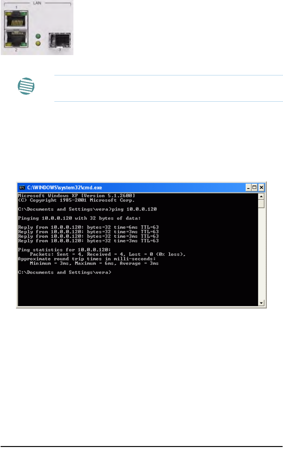
Getting Started with the RADWIN Manager Chapter 4
RADWIN 2000 User Manual Release 2.5.40 4-3
Figure 4-1: LAN ports on the front panel of the IDU-C
If you are not using a direct connection as above, ensure that you have IDU to man-
aging computer connectivity (e.g. through a LAN).
2. Check that you have connectivity to the ODU. You can do this by opening up a com-
mand line session (Start|Run and then type, cmd). At the command prompt, type
ping 10.0.0.120
You should see something like this:
Figure 4-2: Pinging an uninstalled and unconfigured link
Any other response from ping means that the ODU is not responding. Check your
Ethernet connection and that both the IDU and ODU are switched on and then try
again. If you do not succeed, seek assistance from RADWIN Customer Support.
3. Dismiss the command line session.
4. Double-click the RADWIN Manager icon on the desktop, or click Start|Pro-
grams|RADWIN Manager|RADWIN Manager.
The Log-on dialog box appears.
Note
For IDU-E users: The LAN ports are located on the rear panel on the unit.
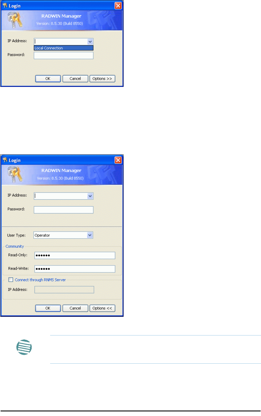
The RADWIN Manager log-on Concept Chapter 4
RADWIN 2000 User Manual Release 2.5.40 4-4
Figure 4-3: First time log-on window
The RADWIN Manager log-on Concept
The RADWIN Manager provides three levels of access in one of two entry modes. To see
them, click Options at any time in the Log on window (Figure 4-3 above). You are offered
an
extended
log-on window:
Figure 4-4: Extended log-on window
At the User Type field, click the list button:
Note
Connection through the RMNS Sever will be available in a future release. If
you have an immediate requirement for this service, please contact
RADWIN Customer Support.
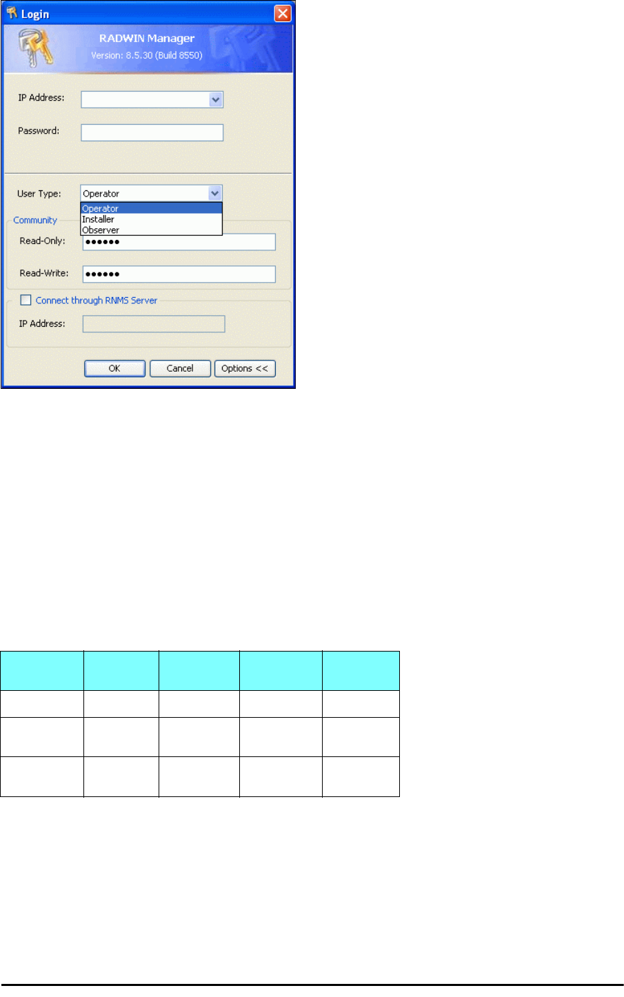
The RADWIN Manager log-on Concept Chapter 4
RADWIN 2000 User Manual Release 2.5.40 4-5
Figure 4-5: Log on window exposing the user types.
There are three user types:
•An
Observer
has read-only access to the link. An Observer can monitor the link, gen-
erate reports, but may not change any link parameters.
•An
Operator
can install and configure the link.
•An
Installer
can, in addition to functioning as an Operator, also change the operating
band. The latter function has legal ramifications, requiring familiarity with local regula-
tions.
The following table summarizes these options:
The Network Manager should change the default passwords as soon as possible.
Continuing the log-on procedure:
5. Type an IP address for the ODU (if you connect through a LAN), or click Local Con-
nection (if you are connected directly to the IDU port).
Table 4-2: User types, default passwords and function
User Type Default
Password Function Community Community
String
Observer
admin
Monitoring Read-Only
public
Operator
admin
Installation,
configuration Read-Write
netman
Installer
wireless
Operator plus
set band Read-Write
netman

Log-on Errors and Cautions Chapter 4
RADWIN 2000 User Manual Release 2.5.40 4-6
6. If your User Type is not Operator, then choose it now.
7. Enter the password.
8. If you are a user with Read-Write permission, click Options to enter the Community
options if required
9. For initial log on:
• Leave the default Community passwords,
netman
for read-write, and
public
for
read-only.
• If Community values were previously defined, enter them under Community in the
Read-Only or Read-Write boxes.
• If you are a user with read-only permission, then you may only log on as Observer.
The RADWIN Manager main window is displayed (see Figure 4-10).
Log-on Errors and Cautions
Unsupported Device
Attempting to connect to an unsupported device on an otherwise valid IP address (for exam-
ple, a LAN printer) will result in the following error message:
Warning
• If you log on using Local Connection, but your physical connection
is not local (i.e. anything other than a direct connection between the
managing computer and the IDU), then any configuration you carry
out may affect other links in the network. Do not do this!
• Network log on (IP address to the ODU) is recommended.
• If you log on via an over-the-air IP address, you will receive a warn-
ing. If you reset the site to which you are connected to factory set-
tings, you can lock yourself out of the link.
Note
• If you log on using Local Connection through a PoE device, you will
need to connect it to the managing computer using a crossed Ether-
net cable.
• The default IP address for the ODU is 10.0.0.120. The subnet mask is
255.0.0.0.
• The actual IP address is defined during link configuration (see Site
Management: IP Address, VLAN and Protocol on page 8-7. See
also, Chapter 19).
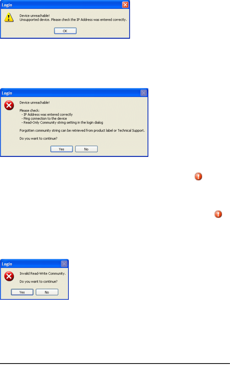
Incorrect IP Address Chapter 4
RADWIN 2000 User Manual Release 2.5.40 4-7
Figure 4-6: Unsupported device message
Incorrect IP Address
If the IP address chosen is invalid or the link is unreachable, the following error message will
be displayed:
Figure 4-7: Unreachable device message
In both of the above situations, if you click No, you will see a warning graphic alongside
the IP Address field.
Incorrect Password
If you type an incorrect password in the Login window, you will see a warning graphic
alongside the password field.
Invalid Read/Write Community String
This will result in the following message:
Figure 4-8: Invalid Community String message
Logging in to the Over-the-Air Site
You can log on to the over-the-air site of an established link (Site B in our example). However,
you will be first offered the following caution:
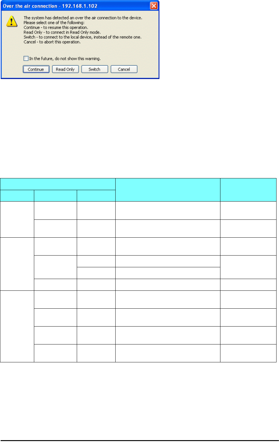
Continuing without an IP Address Chapter 4
RADWIN 2000 User Manual Release 2.5.40 4-8
Figure 4-9: Logging on to an over-the-air site
Continuing without an IP Address
The RADWIN Manager provides limited “offline” functionality when there is no accessible
IDU/ODU. It is primarily for setting managing computer related parameters, running the Link
Budget Calculator or viewing online Help. The offline functionality is shown in Table 4-3
below. The table does not show menu items grayed out.
Changing the Log-On Password
To change the log on password:
1. From the Tools menu, select Change Password.
The Change Password dialog box appears.
Table 4-3: RADWIN Manager: Offline Functionality
Menu level Function Reference
Top +1 +2
File
Log Off Return to log-on dialog. Same as Log Off
button
Exit Exit the RADWIN Manager. Same as Exit
button
Tools
Change
Password Change the log-on password page 4-8
Events Log Clear Events Clear local events log page 9-17
Save to File Save events log data to a file
Preferences Set managing computer preferences
Help
RADWIN
Manager Help View online help version of the User Manual
Link Budget
Calculator Calculator opened in default browser Chapter 21
Get Diagnostics
Information Obtain system information page 9-1
About RADWIN
Manager RADWIN Manager build information
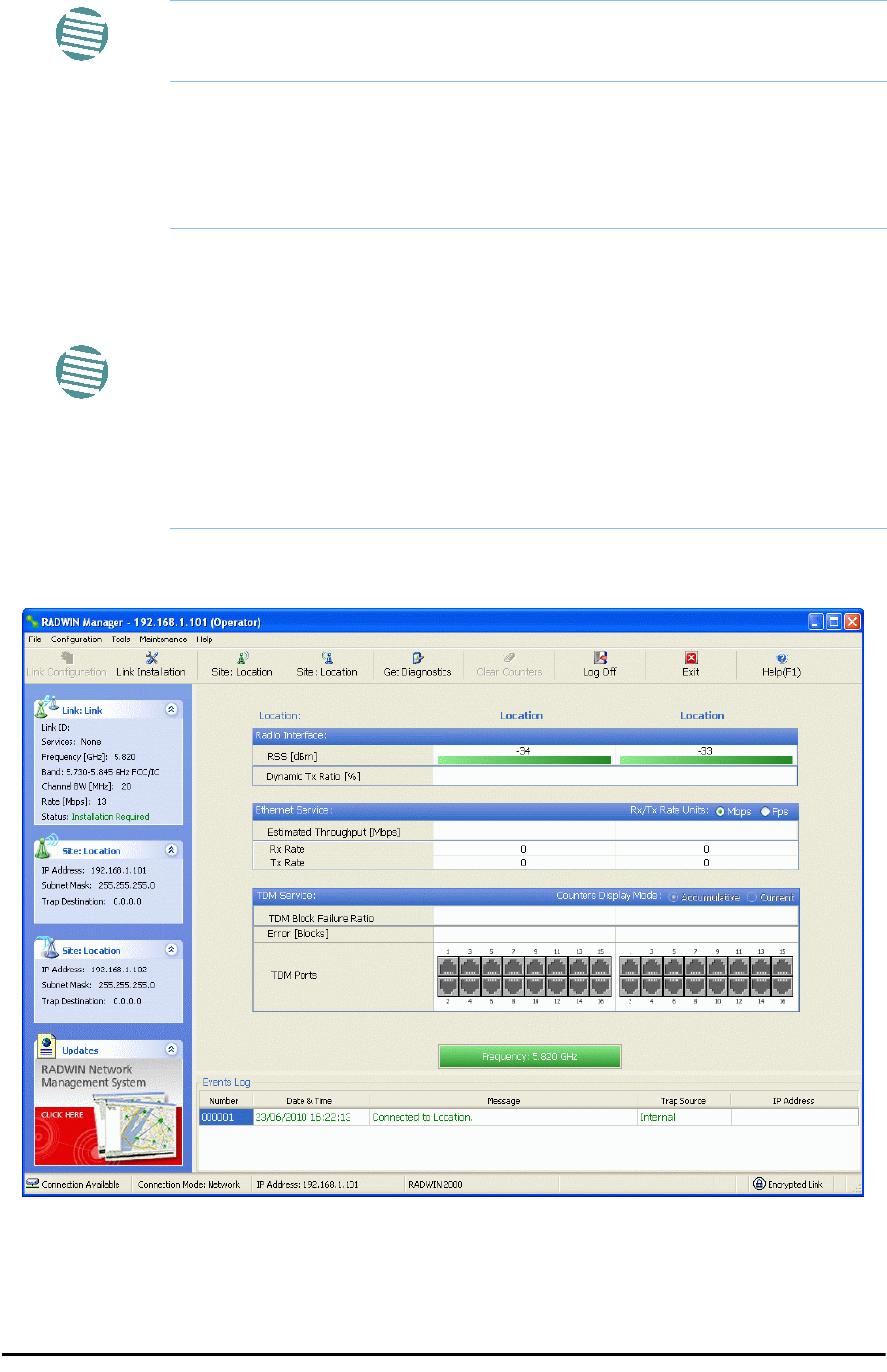
First steps Chapter 4
RADWIN 2000 User Manual Release 2.5.40 4-9
2. Enter the current password, and the new password.
3. Click OK to confirm.
First steps
At this point the main window of the RADWIN Manager should be displayed:
Figure 4-10: Opening RADWIN Manager window prior to installation - IDU-C
Note
A valid log-on password must contain at least five characters excluding
SPACE, TAB, and any of “>#@|*?;.”
Note
For what follows, it is assumed that you have set the IP addresses of both
ODUs. For the purposes of illustration, we will use the following IP
addresses:
Our managing computer has its NIC set to IP address 192.168.1.100. The
log-on ODU is set to IP address 192.168.1.101 and the over-the-air ODU is
set to 192.168.1.102. The Subnet Mask for both sites is 255.255.255.0 and
the Default Gateway is left unset. We will maintain this arrangement
throughout the remainder of this manual.
Other defaults are shown in Table 4-4.

First steps Chapter 4
RADWIN 2000 User Manual Release 2.5.40 4-10
A detailed field by field description of the contents of the RADWIN Manager main window
may be found in Chapter 6.
The procedure required to make the link functional has three phases:
1. Link Installation - which we will detail below.
Installation actually gets the link operational by setting the link parameters. It uses a fixed
channel at the lowest possible modulation, BPSK at 6.5Mbps and will work under the harsh
interference condition.
2. Link Configuration - described in Chapter 7.
Configuration provides much the same functionality as Installation, but for a running link.
A fallback to Installation mode is provided for situations which cannot be handled without
resetting the link, such as antenna realignment and IDU or ODU replacement.
The Link Installation and Configuration phases are both carried out with Wizards, which
“walk you through” the processes. The Wizards are visually quite similar and will be
described in detail below.
3. Site Configuration - described in Chapter 8.
Site specific configuration for each side of the link is available at any time - under a run-
ning link or under the restricted Installation mode.
Site Configuration consists of a set of panels, which may be invoked individually in any
order, as needed.
Note
The Dynamic Tx Ratio bar only appears for model RADWIN 2000 C
Note
During the installation procedure, the definition of all parameters is
automatically applied to both sides of the link.
Caution
• The ODUs as supplied by RADWIN are set up with a factory default
band. If for some reason the default band needs to be changed, it
should be done before link Installation. The procedure is set out in
Chapter 20.
• Use of an incorrect band may be in violation of local regulations.
Note
An installed and configured link can be returned to installation mode for re-
installation and configuration from last settings or from factory settings.
• Reversion to installation mode requires a complete break in the link
service
• Configuration mode may vary the service throughput and quality, but
without a service break

Default RADWIN 2000 Settings Chapter 4
RADWIN 2000 User Manual Release 2.5.40 4-11
Default RADWIN 2000 Settings
The default settings of the RADWIN 2000 configuration parameters are listed in the second
column of Table 4-4 below. The third column shows the values we use in this manual for
illustrative purposes.
Using RADWIN Manager Spectrum View
Prior to running the Installation Wizard (Chapter 5), you may use the RADWIN Manager
Spectrum View utility.
The RADWIN Manager Spectrum View utility is an RF survey tool designed to support the link
installation prior to full link service activation. The tool provides comprehensive and clear
information enabling easier, faster and better quality installations.
To launch Spectrum View, go to the main window menu (Figure 4-11) and click Tools |
Spectrum View. A display similar to the following appears:
Table 4-4: Default Settings
Parameter Default Value Illustrative Value
Factory default band Product dependent 5.820GHz
ODU IP Address 10.0.0.120 192.168.1.101 and 102
Subnet Mask 255.0.0.0 255.255.255.0
Trap destination 0.0.0.0 0.0.0.0
RADWIN Manager log-on
passwords
Observer admin
Operator admin
Installer wireless
Link ID Link EBG_20561334
Link Name Name TPSF_BTT
Site 1 Site A
Site 2 Site B
Location (per site) Location A B
Name (per site) Name Here There
Contact (per site) Person John Mary
Link Password wireless-bridge
Rate Adaptive
Ethernet Configuration Auto Detect
Radio Link Failure Actions No action
Bridge or Hub mode Hub Mode, Aging time = 300 sec
Community values Read-write – netman
Read-only – public
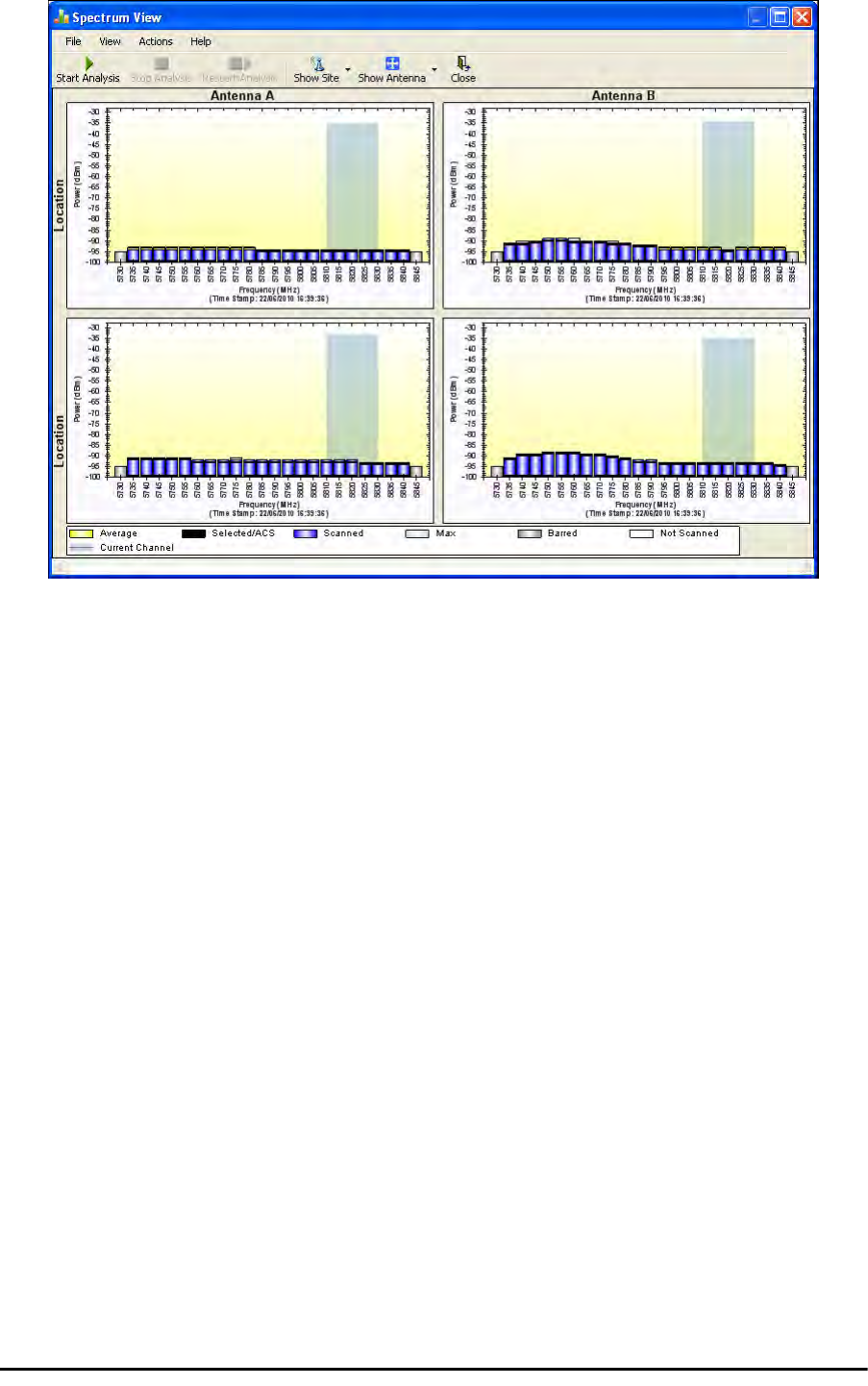
Using RADWIN Manager Spectrum View Chapter 4
RADWIN 2000 User Manual Release 2.5.40 4-12
Figure 4-11: Spectrum View - Opening Display on installed link
See Chapter 23 for detailed information about operating Spectrum View and understanding
the displayed statistics.

RADWIN 2000 User Manual Release 2.5.40 5-1
Chapter 5
Installing the Link
Overview
The installation is carried out using the Installation wizard. Its operation is detailed in the fol-
lowing pages in a tutorial style.
For the purpose of explanation, we will set up a laboratory link with the following characteris-
tics:
•Channel selection: Automatic
•Antennas: Dual at both sites
•Services: Ethernet + 7xE1 on ports 1, 2, 3, 8, 10, 11, 14. It is unlikely that you would
use a non-contiguous set of ports - but this shows that if required, it can be done.
The Installation wizard has steps as shown in Table 5-1 below.
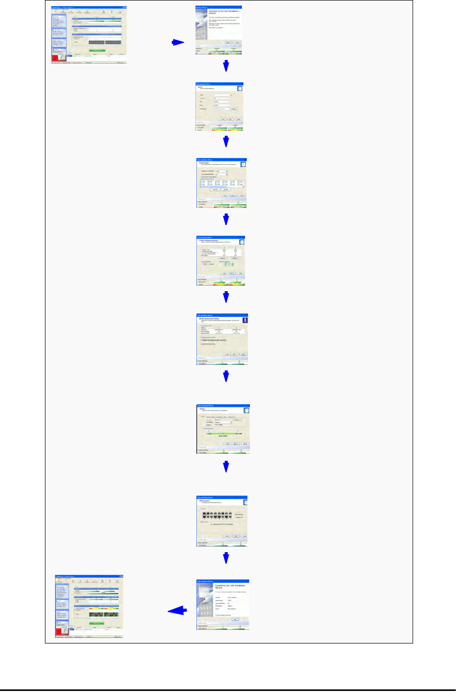
Overview Chapter 5
RADWIN 2000 User Manual Release 2.5.40 5-2
Table 5-1: Link Installation Wizard
1Wizard welcome
2System parameters
•Link ID
•Site details
3Channel settings - ACS
Configuration
4Tx Power and antenna
settings, MIMO or
Diversity
5HSS Settings
6
Services - Types
• Ethernet
•TDM
Adaptive or fixed, Jitter
Buffer, MHS, Ethernet
Ring, QoS
7Set TDM Clock
Parameters
8Wizard summary and
completion
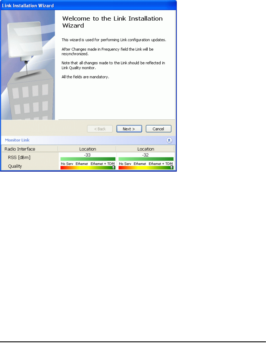
Installation Chapter 5
RADWIN 2000 User Manual Release 2.5.40 5-3
Installation
Step 1, Start the Wizard
In the tool bar of the RADWIN Manager main window, click the Link Installation button.
The Link Installation button is only accessible if the antennas are properly aligned. If this box
is “grayed out”, you should align the antennas as set out in Chapter 3 on page 3-16.
The Installation Wizard opens:
Figure 5-1: Link Installation Wizard
The bottom data area reproduces the corresponding data from the main window - which the
above panel obscures. See Chapter 6 for a field by field description of this data area.
Click Next to proceed with the installation procedure.
Step 2, System Parameters
The system dialog box opens:
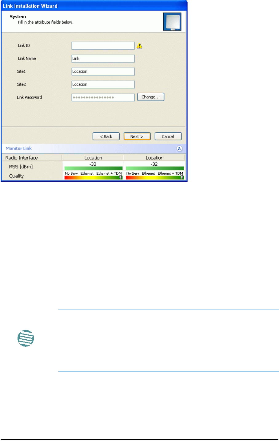
Installation Chapter 5
RADWIN 2000 User Manual Release 2.5.40 5-4
Figure 5-2: Installation Wizard, System dialog box
To complete Installation Step 2:
1. Enter a Link ID. The Link ID must be identical for both ODUs in the link, oth-
erwise they will not communicate. The Link ID must include at least eight
alphanumeric characters. Up to 24 characters are allowed. You should use a Link ID
composed of both alphabetic and numeric characters.
2. Enter a Link Name for the link identification. The default name is “Link”. You should
change it.
3. Enter names for Site 1 and Site 2. The default names are both “Location”. You should
change them. Throughout this manual, we use A for Site 1 and B for Site 2.
4. Optionally enter a new Link Password.
Here is our completed System panel:
Note
If the Link Password is incorrect a link is established but configuration
cannot be performed and no services are available. A new link password
may be obtained from RADWIN Customer Support or use the alternative
password supplied with the product.
The link password is peculiar to the link itself and should not be confused
with the RADWIN Manager log on password.
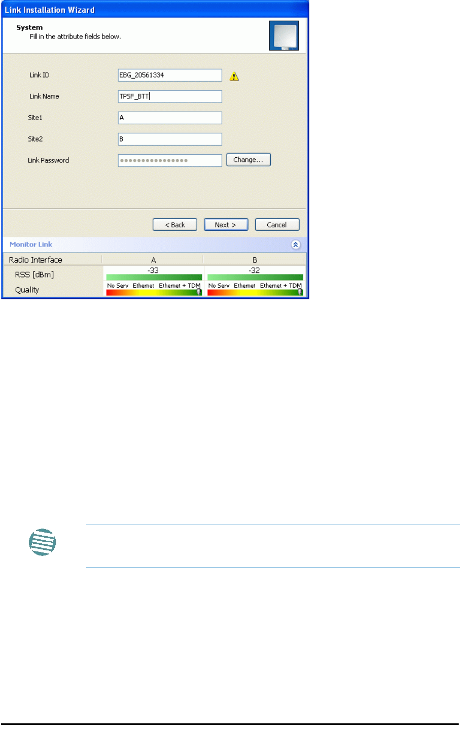
Installation Chapter 5
RADWIN 2000 User Manual Release 2.5.40 5-5
Figure 5-3: Installation Wizard, System dialog box filled out
5. Click Next.
The default link with a rate of 6.5 Mbps is evaluated.
The Channel Setting dialog box appears. Proceed to Channel Settings, below.
Changing the Link Password
The default password is
wireless-bridge
. Optionally, you can change the link password as
explained here.
To change the link password:
1. Click the Change button in the System dialog box.
The Change Link Password dialog box opens.
Note
Use the Hide characters check box for maximum security
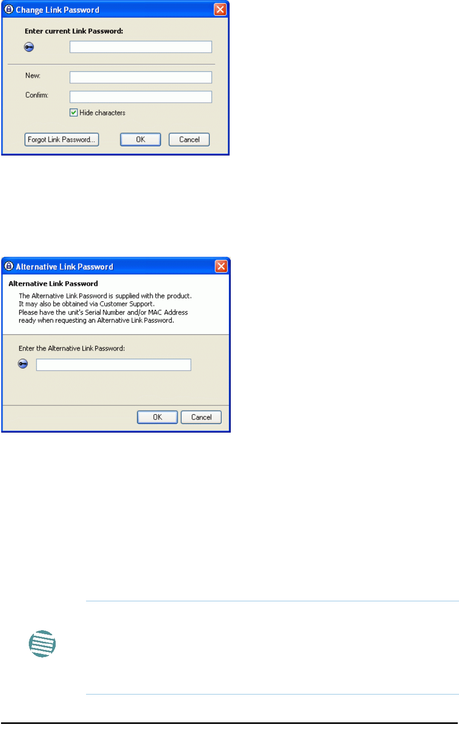
Installation Chapter 5
RADWIN 2000 User Manual Release 2.5.40 5-6
Figure 5-4: Change Link Password dialog box
2. Enter the current link password (The default link password for a new ODU is
wire-
less-bridge
).
If you have forgotten the Link Password, click the Forgotten Link Password button.
The following window is displayed:
Figure 5-5: Lost or forgotten Link Password recovery
Follow the instructions to use the Alternative Link Password, and click OK to finish.
You are returned to the window in Figure 5-4 above. Continue with the next step.
3. Enter a new password.
4. Retype the new password in the Confirm field.
5. Click OK.
6. Click Yes when asked if you want to change the link password.
7. Click OK at the
Password changed
success message.
Note
• A link password must contain at least eight but no more than 16
characters excluding SPACE, TAB, and any of “>#@|*?;.”
• Restoring Factory Defaults returns the Link Password to
wireless-
bridge
.
• If the link is inactive, then the link password may also be changed
from the Site Configuration dialogs. See page 8-13.
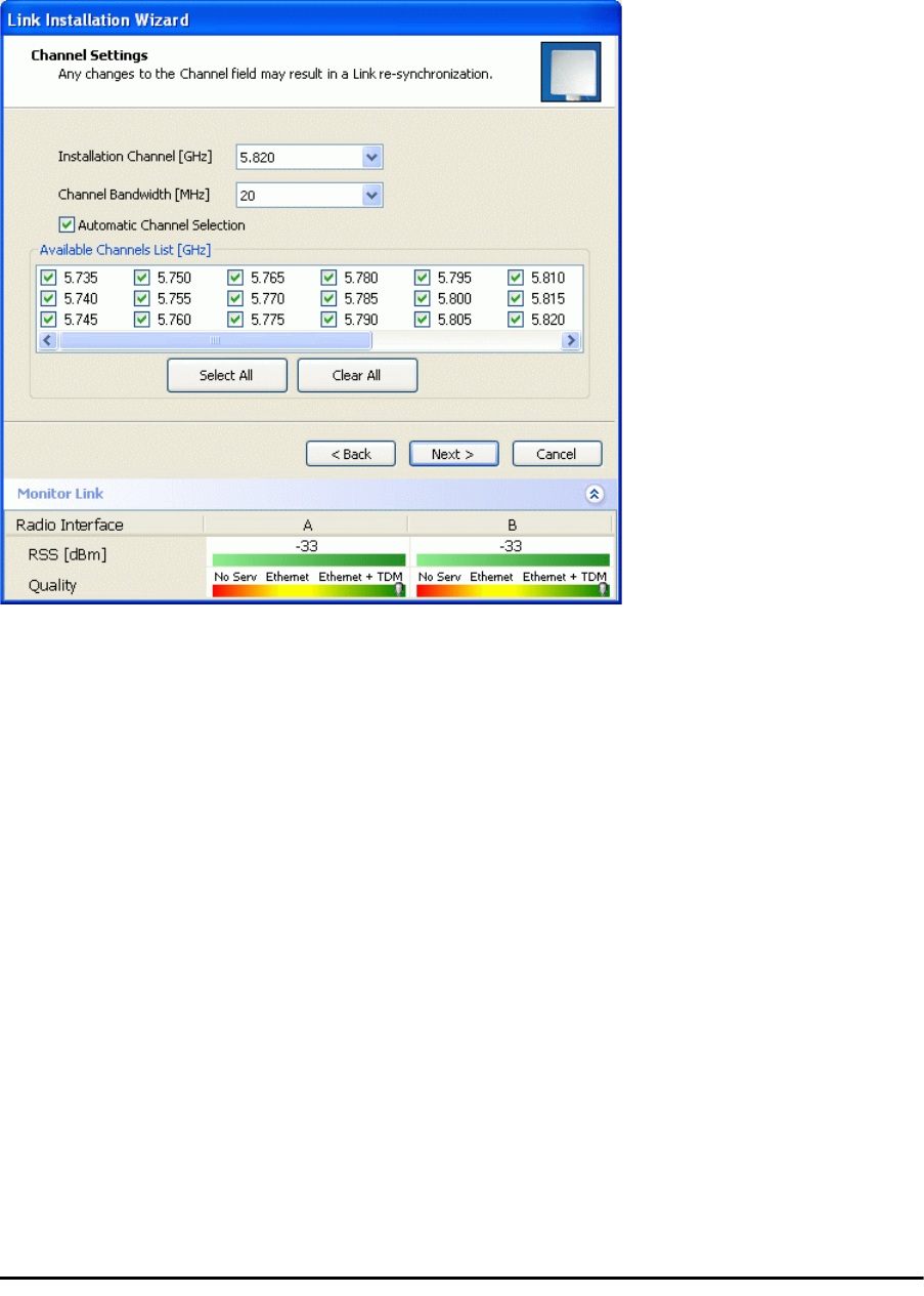
Installation Chapter 5
RADWIN 2000 User Manual Release 2.5.40 5-7
Step 3, Channel Settings
RADWIN 2000 systems have a feature called Automatic Channel Selection (ACS). In the event
of sync loss, ACS chooses the first available channel in a list of monitored channels nominated
in the Channel settings window of Figure 5-6 below. A channel switch takes place suffi-
ciently fast as to ensure no loss of service.
Figure 5-6: Channel Settings - Automatic Channel Selection
The default frequency for the product is shown.
To select channels to be used by the link:
1. Select the installation frequency from the Installation Channel box.
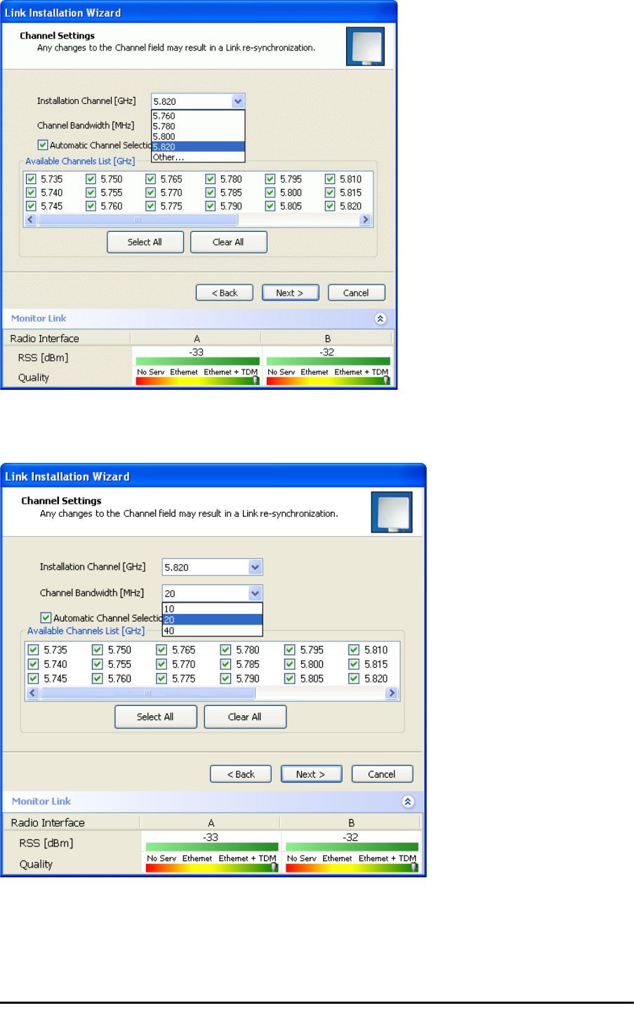
Installation Chapter 5
RADWIN 2000 User Manual Release 2.5.40 5-8
Figure 5-7: Channel Settings - Showing available installation rates
2. Choose the required Channel Bandwidth.
Figure 5-8: Channel Settings - Showing available Channel Bandwidths
3. Click the check box if Automatic Channel Selection is required.
4. The Available Channels List contains all of the allowable channels for the link. Check
the channels that can be automatically selected.
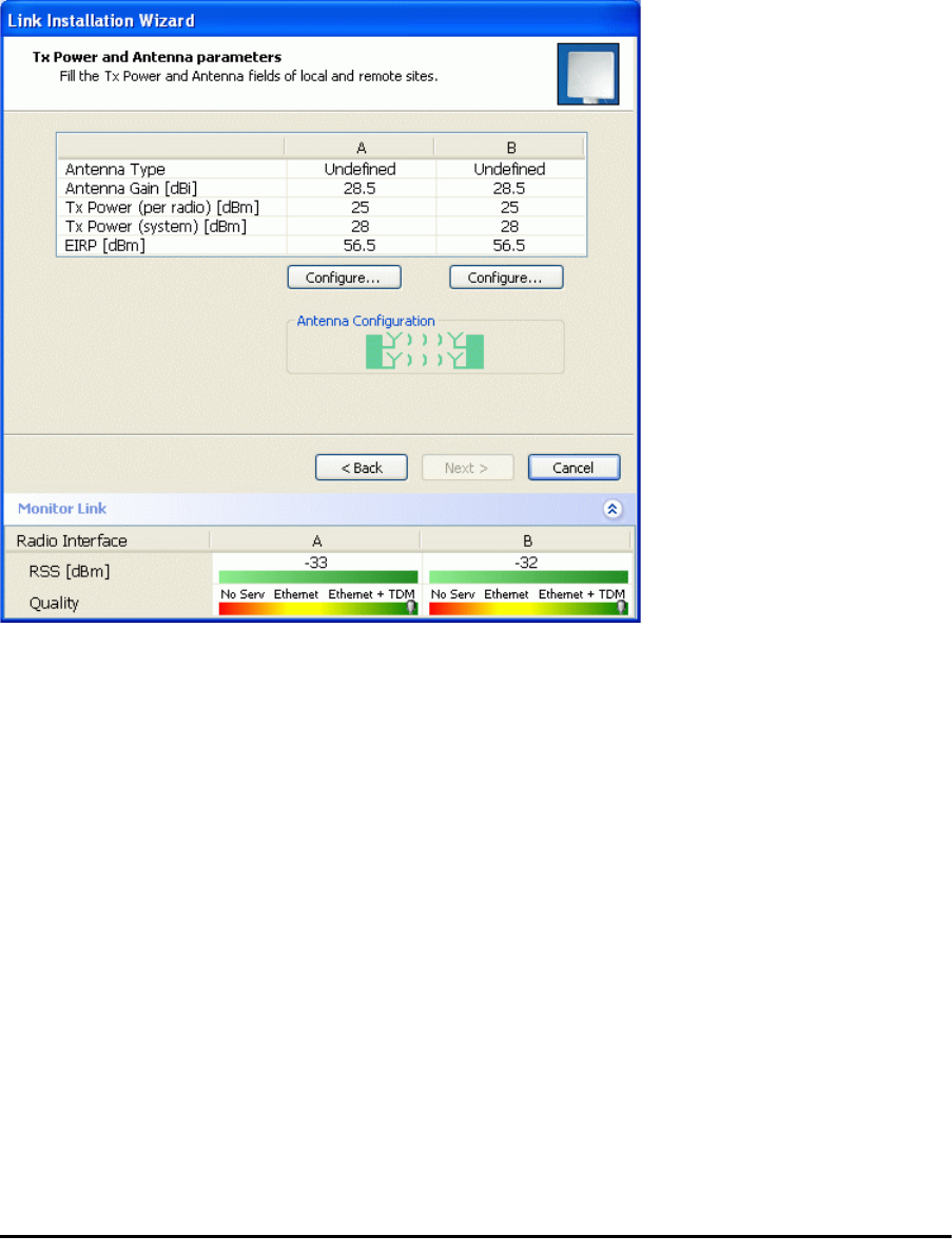
Installation Chapter 5
RADWIN 2000 User Manual Release 2.5.40 5-9
Selecting a new channel causes the system quality to change. The Quality bar pro-
vides an indication of the link quality from No serv(ice) (red) to Ethernet + TDM
(green) as shown in the bottom of Figure 5-7 above.
5. Click Next.
Step 4, Tx Power and Antenna Settings
The Tx Power and Antenna Parameters dialog appears.
.
Figure 5-9: Transmission Power and Antenna Parameters
The choice of Tx Power, antenna gain and cable loss (between the radio and the antenna)
determines the EIRP and is affected by such considerations as radio limitations and regulatory
restrictions.
Before proceeding to antenna installation details, the following background information
should be considered:
About Single and Dual Antennas
Each RADWIN 2000 ODU is made of two radio transceivers (radios). The radios make use of
algorithms that utilize both MIMO and Diversity resulting in enhanced capacity, range and link
availability. The number of antennas (i.e. radios) used is determined by user configuration
and by automatic system decisions, explained below.
Dual Antennas at Both Sites
When using dual antennas at both sites (single bipolar antenna or two mo-unipolar antennas)
you can choose between MIMO Mode and Diversity Mode.

Installation Chapter 5
RADWIN 2000 User Manual Release 2.5.40 5-10
MIMO Mode
With MIMO the system doubles the link capacity. At the same time, it keeps the same rate
and modulation per radio as was used with single antenna, thus increasing capacity, range
and availability.
For example with a dual antenna RADWIN 2000 can transmit at modulation of 64QAM and
FEC of 5/6 and get an air rate of 130 Mbps, compared to 65 Mbps with single antenna.
To work in this mode, each antenna port must be connected to an antenna, the RSS level in
both receivers should be balanced and a minimal separation between the antennas must be
maintained. (For example, by using dual polarization antennas a cross polarization separation
is attained).
Upon selecting Antenna Type as Dual, RADWIN 2000 automatically selects MIMO mode and
doubles the air rates.
RADWIN Manager indicates a case of unbalanced RSS between the two antennas.
Diversity Mode
Diversity Mode uses two antennas to improve the quality and reliability of the link. Often,
there is not a clear line-of-sight (LOS) between transmitter and receiver. Instead the signal is
reflected along multiple paths before if-ally being received.
Each such “bounce” can introduce phase shifts, time delays, attenuations, and even distor-
tions that can destructively interfere with one another at the aperture of the receiving
antenna. Antenna diversity is especially effective at mitigating these multi-path situations.
This is because multiple antennas afford a receiver several recordings of the same signal.
Each antenna will be exposed to a different interference envy-remnant. Thus, if one antenna
is undergoing a deep fade, it is likely that another has a sufficient signal. Collectively such a
system can provide a or-bust link.
Antenna diversity requires antenna separation which is possible by using a dual-polarization
antenna or by two spatially separated antennas.
Use Diversity instead of MIMO in the following situations:
• When the system cannot operate in MIMO Mode
• When one of the receivers has high interference compared to the second receiver (i.e.
the system is “unbalanced”)
• When you achieve higher capacity in Diversity Mode than in MIMO Mode
• When high robustness is of importance and the capacity of Diversity Mode is sufficient
(up to 25 Mbps full duplex)
Single Antennas at Both Sites
By selecting a single antenna at both sites the ODUs operate with a single radio that is con-
nected to the ANT 1 connector. The second radio is automatically shut down.
Single at One Site, Dual Antennas at the Other
In this mode one of the sites uses the ODU with a single antenna while the other site uses the
ODU with a dual antenna.
The advantages in this mode in comparison to using a single antenna in both sites are dou-
bled total Tx Power and additional polarization and/or space diversity (depending on the
polarization of installed antennas).

Installation Chapter 5
RADWIN 2000 User Manual Release 2.5.40 5-11
The air rates used in this mode are same as when using single antennas in both sites.
Table 5-2 summarizes the situation:
The rates used by RADWIN 2000 are shown in Table 5-3 below:
Table 5-2: MIMO - Diversity settings
Number of
Antennas Mode Graphic Indication Max Full
Duplex
Capacity
Site A Site B
2 2
MIMO 50 Mbps
Diversity 25 Mbps
2 1 25 Mbps
1 2 25 Mbps
1 1 25 Mbps
Table 5-3: RADWIN 2000 Air rates
Antenna Modulation FEC Air-Rate
[Mbps]
Single BPSK 1/2 6.5
Single QPSK 1/2 13
Single QPSK 3/4 19.5
Single 16QAM 1/2 26
Single 16QAM 3/4 39
Single 64QAM 2/3 52
Single 64QAM 3/4 58.5
Single 64QAM 5/6 65
Dual BPSK 1/2 13
Dual QPSK 1/2 26
Dual QPSK 3/4 39
Dual 16QAM 1/2 52
Dual 16QAM 3/4 78
Dual 64QAM 2/3 104

Installation Chapter 5
RADWIN 2000 User Manual Release 2.5.40 5-12
Considerations for Changing Antenna Parameters
Let:
max Available Tx Power denote the maximum Tx Power practically available from an
ODU. It appears as Tx Power per Radio in Figure 5-10
below.
maxRegEIRP denote the maximum EIRP available by regulation. It will be determined by
three factors:
• per band/regulation
• per channel bandwidth
• antenna gain
It appears in Figure 5-10 as Max EIRP.
maxRegTxPower denote the maximum regulatory Tx Power for the equipment, also
having regard the above three points.
Then, the following relationship must be satisfied: ... (*)
These parameters are controlled as follows:
To set Tx Power and configure antennas:
1. Click the Configure buttons in turn to configure the antennas on both sides of the
link. Each one offers a dialog like this:
Dual 64QAM 3/4 117
Dual 64QAM 5/6 130
Table 5-3: RADWIN 2000 Air rates (Continued)
Antenna Modulation FEC Air-Rate
[Mbps]
maxAvailableTxPower min maxRegEIRP
AntennaGain CableLoss maxRegTxPower+– ()
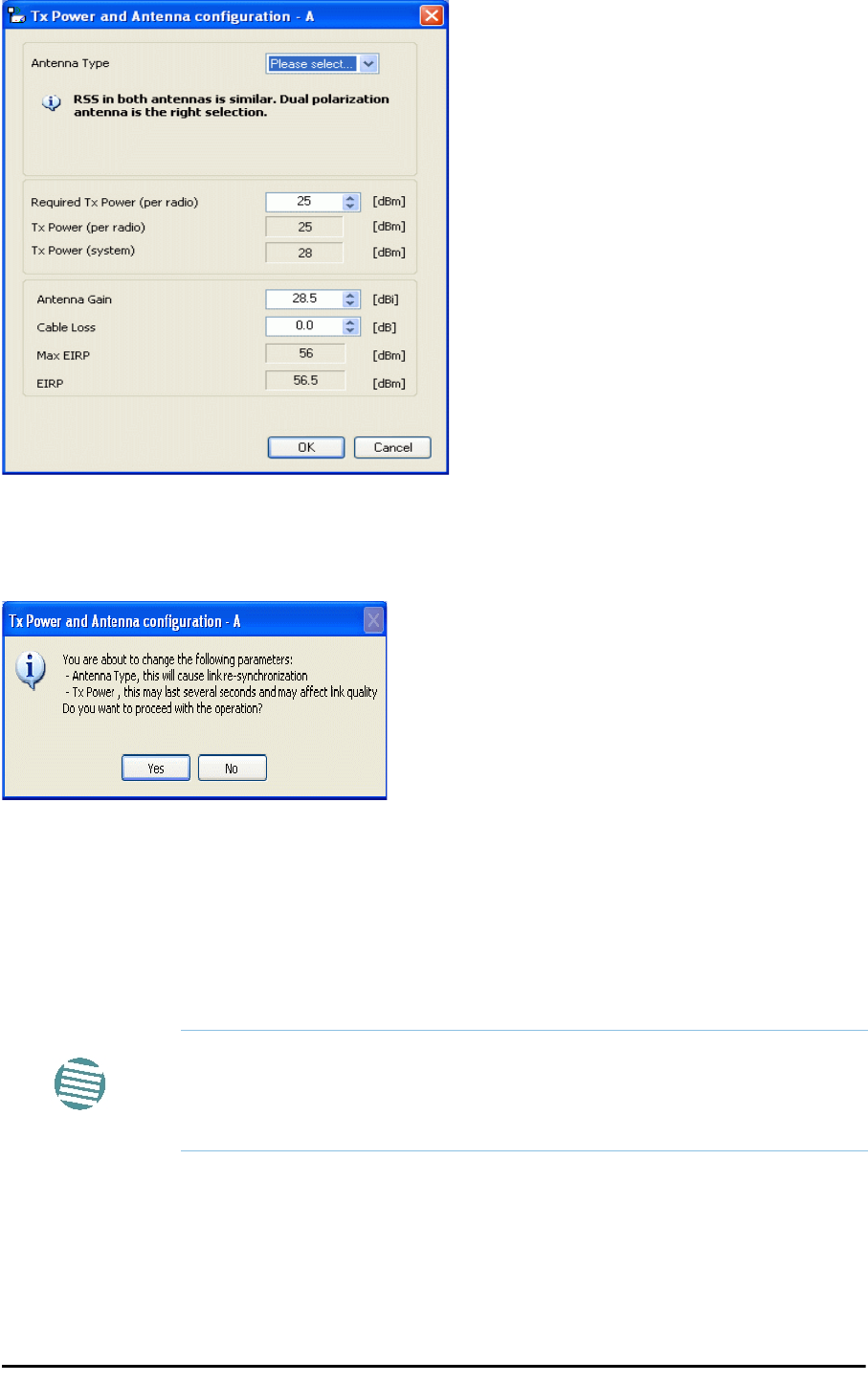
Installation Chapter 5
RADWIN 2000 User Manual Release 2.5.40 5-13
Figure 5-10: Antenna configuration dialog
2. Choose the antenna type and required transmission (Tx) power for the first site and
click OK. You will receive the following warning:
Figure 5-11: Antenna type change warning
3. Repeat the process for the second site.
4. At the same time you can set the Antenna Gain and Cable Loss.
The Tx Power (per radio) indicates the power of each radio inside the ODU and is
used for Link Budget Calculations. The Tx Power (System) shows the total transmis-
sion power of the ODU and is used to calculate the EIRP according to regulations.
If you choose to set the Antenna Gain and Cable Loss, you will receive the following
warning message:
Note
To see the relationship between Tx Power (radio) and Tx Power (system),
note that so that if you double the power in
milliWatts (for two radios) then dBm will increase by .
dBm 10 milliWatt
10
log=
10 2 3
10
log
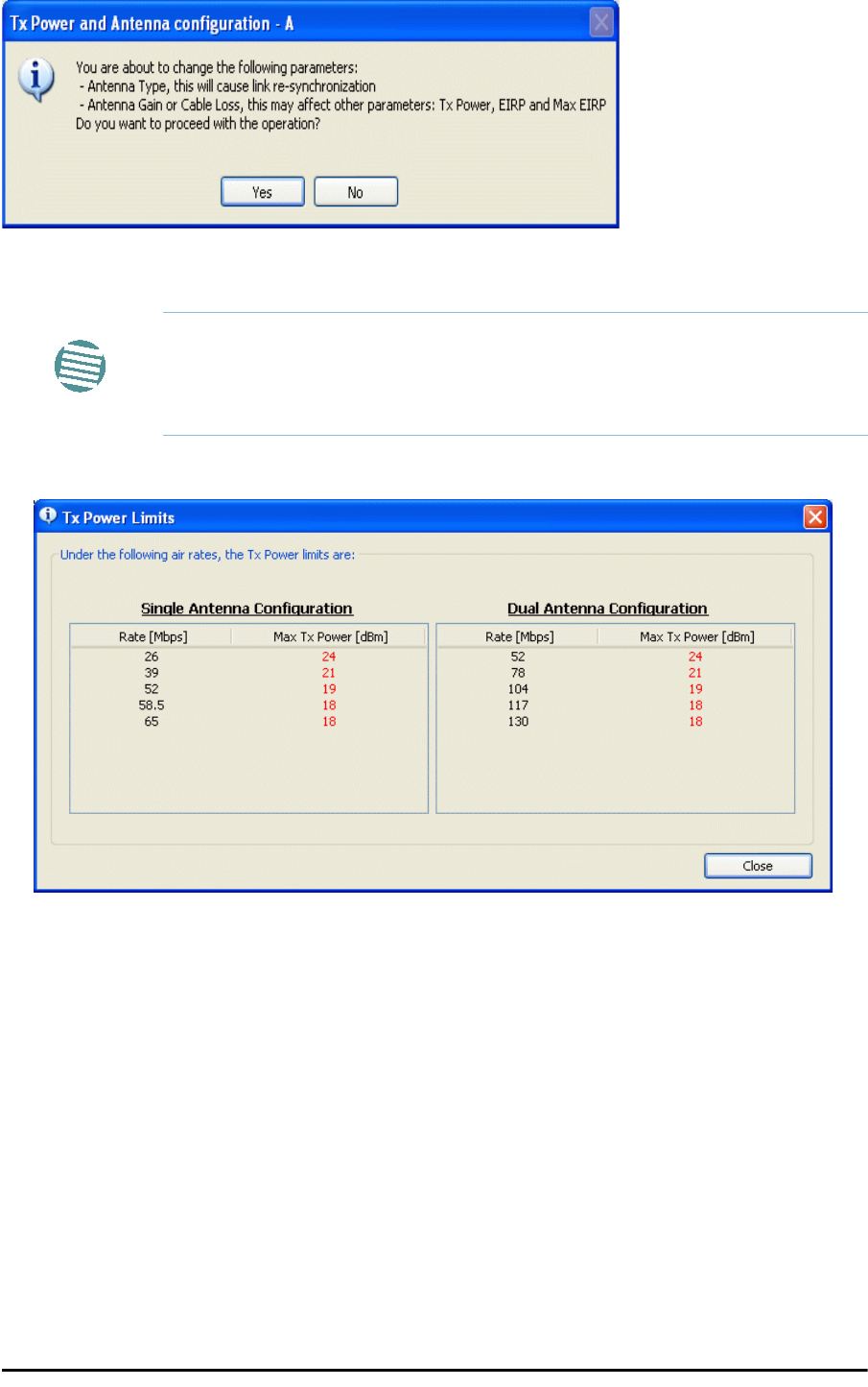
Installation Chapter 5
RADWIN 2000 User Manual Release 2.5.40 5-14
Figure 5-12: Antenna parameters change warning
If inequality (*) above is violated, then the following warning window is displayed:
Figure 5-13: Tx Power Limits
The precise relationship between the items in inequality (*) and the window of
Figure 5-10 is as follows:
• Required Tx Power (per radio) will be adjusted down to the lesser of the value
entered and maxAvailableTxPower
• Tx Power (system) is maxAvailableTxPower + 3 (for 2 radios)
•Max EIRP is maxRegEIRP.
•EIRP is maxAvailableTx Power + Antenna Gain - Cable Loss
The table in Figure 5-13 only shows rates where the maximum Tx Power is the lim-
itation, rather than regulations. When you close the window of Figure 5-13, the
change you requested will not be honored, and you will need to try again.
Note
• The Max EIRP level will be automatically set according to the selected
band and regulation.
• The EIRP level is the sum of the System Tx Power and the Antenna
Gain minus the Cable Loss.
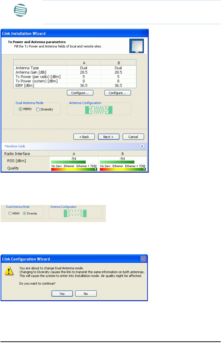
Installation Chapter 5
RADWIN 2000 User Manual Release 2.5.40 5-15
Figure 5-14: Antennas configured for two dual and Tx power 5 dBm
5. Choose Dual Antenna mode if appropriate. The green Antenna Configuration diagram
indicates the active state. For dual antennas in Diversity mode it looks like this:
There are intermediate modes available for dual antennas opposite a single antenna
as set out on page 5-9 above.
If you make a change you will see a warning similar to this:
A similarly worded warning applies to a s switch from MIMO to Diversity mode
6. When you are finished with Tx Power configuration, Click Next.
Note
Since our demonstration link is entirely indoors, we have reduced Tx Power
to 5 dBm to obtain a realistic RSS. Although this is much too low for field
use, the method is general.
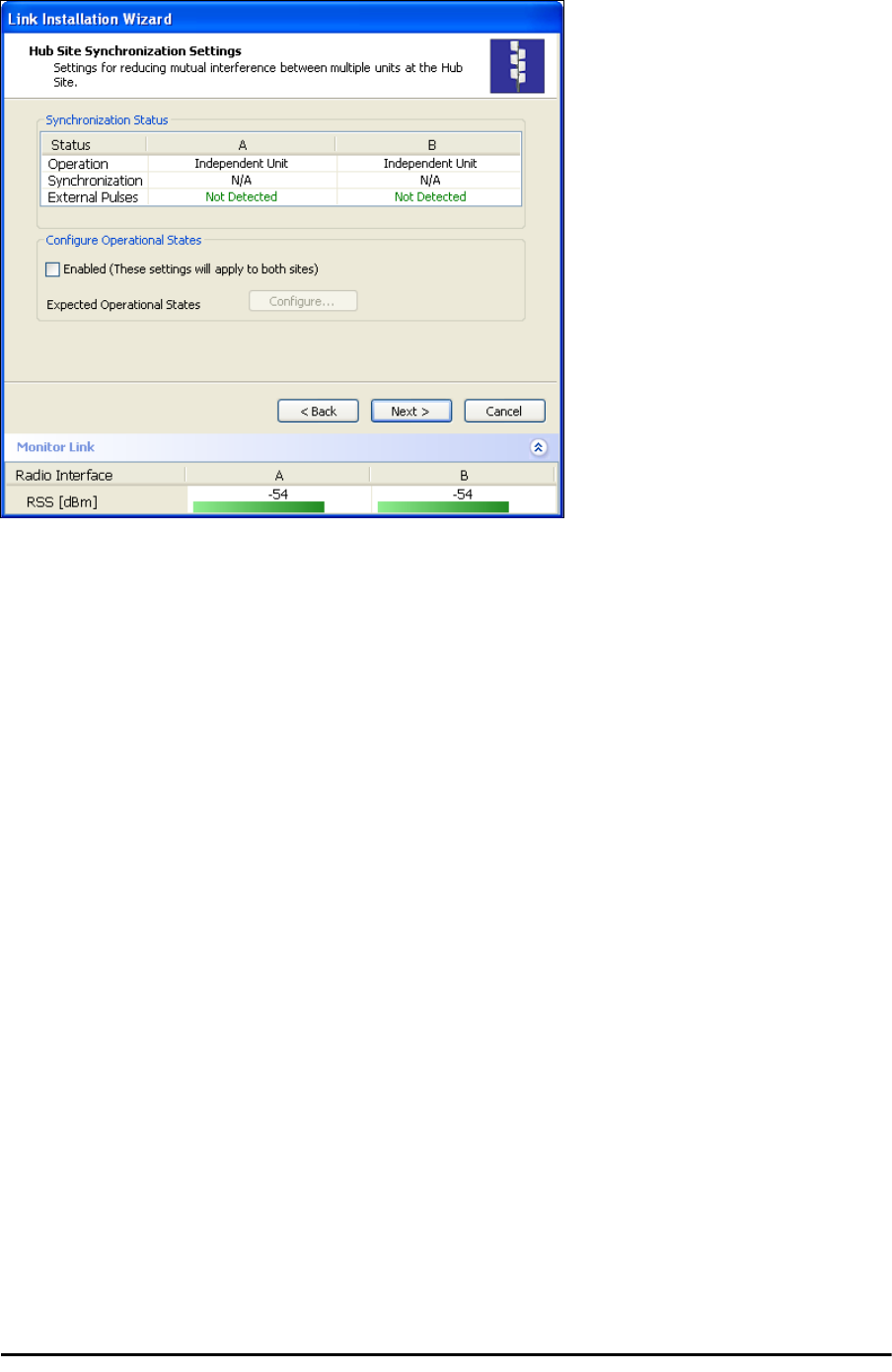
Installation Chapter 5
RADWIN 2000 User Manual Release 2.5.40 5-16
Step 5, Hub Site Synchronization Settings
Figure 5-15: HSS Settings
The Synchronization Status dialog box displays the current status of each side of the link. See
Chapter 10 for instructions about installing and configuring collocated links. If you do not
require HSS, click Next.
Step 6, Services
The Services dialog appears:
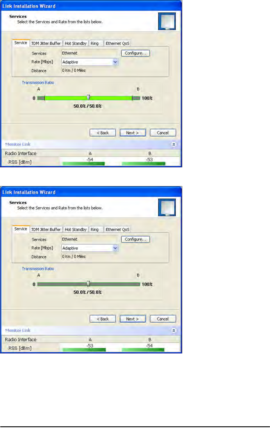
Installation Chapter 5
RADWIN 2000 User Manual Release 2.5.40 5-17
Figure 5-16: Services and Rates - RADWIN 2000 C only
Figure 5-17: Services and Rates for RADWIN 2000 collocated as a client
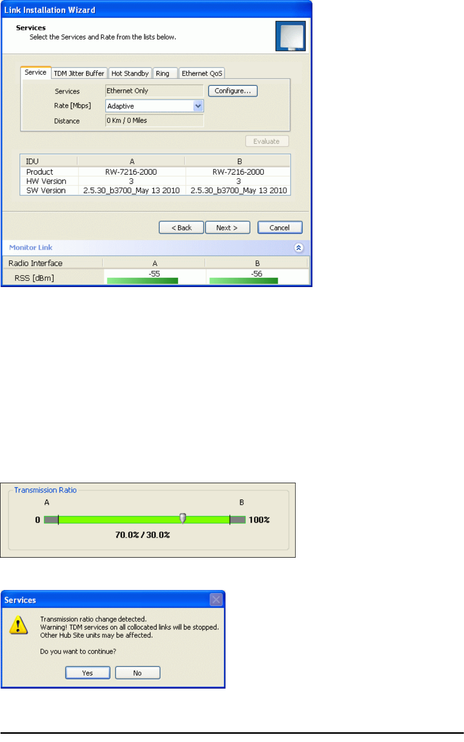
Installation Chapter 5
RADWIN 2000 User Manual Release 2.5.40 5-18
Figure 5-18: Services and Rates for models RADWIN 2000 L and RADWIN 2000 PDH
For -
• a collocated link
• Models RADWIN 2000 L
and
RADWIN 2000 PDH
proceed to TDM Services selection.
Otherwise, you can use the green slider to allocate asymmetric Ethernet capacity by changing
the Transmission Ratio between the sites.
For example: Suppose that during congestion, you might want to use 70% for the downlink
and 30% for the uplink. Your choice would typically be based on your experienced traffic load
during periods of congestion.
If you change the Transmission Ratio, you will be offered the following warning:
Otherwise, click Yes to continue.

Installation Chapter 5
RADWIN 2000 User Manual Release 2.5.40 5-19
Limitations on the use of Asymmetric Allocation
For non collocated links, capacity allocation between uplink and downlink traffic is determined
automatically according to actual Ethernet traffic and air interface conditions. Your manual
allocation using this feature “cuts in” during congestion.
Asymmetric Allocation and Collocation
The use of Asymmetric Allocation is limited where the link is collocated. Possible scenarios are
shown in Table 5-4. In all cases where Asymmetric Allocation is available, it is static for all
traffic conditions.
The Services and Rates dialog as shown in Figure 5-16 will be different:
Caution
If you have active collocated links, or if you are uncertain of whether
collocated links provide TDM services do not use this option now. You can
do it at a less disruptive time using the Link Configuration (Chapter 7).
Table 5-4: Asymmetric Allocation with Collocated Links - Scenarios
HSS Master HSS Client Scenario: If you try to... Result Remarks
RADWIN 2000
WinLink 1000
Change master to
asymmetric allocation
Link down Reversion to 50/50 restores link
RADWIN 2000
• Releases prior to 2.4 -
Link down
• Release 2.4 later (RAD-
WIN 2000 PDH and
RADWIN 2000 L series)
- Link down
• Release 2.4 and later
(RADWIN 2000 C
series) - TDM services
stopped, link set to
transmission ratio of
master
Release 2.4 and later (RADWIN
2000 C series) - Asymmetric
Allocation slider visible but
cannot be changed
RADWIN 2000
WinLink 1000
RADWIN 2000 Change client to
asymmetric Asymmetric Allocation slider
not displayed You cannot do this
WinLink 1000
WinLink 1000
RADWIN 2000 Change client to
asymmetric Asymmetric Allocation slider
not displayed You cannot do this
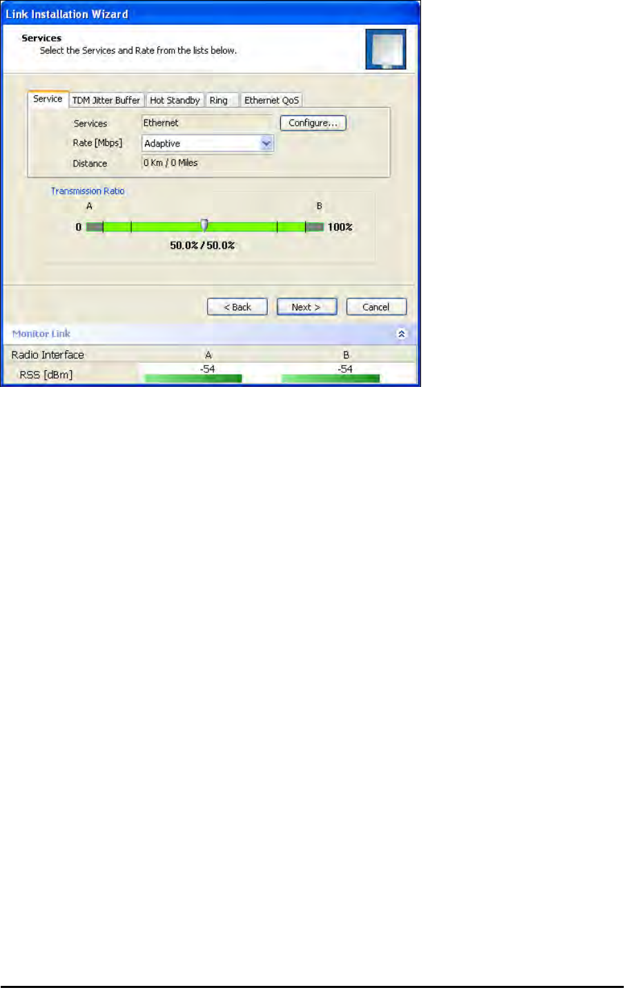
Installation Chapter 5
RADWIN 2000 User Manual Release 2.5.40 5-20
Figure 5-19: Services and Rates - RADWIN 2000 C master, RADWIN 2000 clients
The yellow areas should not be used. Using those areas, you may loose the collocated link
with the longest distance between sites.
Asymmetric Allocation and TDM
You cannot use this feature when TDM services are used. Selection of TDM ports as in the
next section will reset the Ethernet balance to 50% in each direction and the green slider will
not appear in subsequent Installation or Configuration runs.
Cancelling TDM port use will make the allocation bar reappear, re-enabling asymmetric Ether-
net traffic allocation.
If you are not using TDM services, clicking Next will take you to Step 8, and completion of
the installation. Your Ethernet capacity allocation will be reflected in Figure 5-34 below.
TDM Services selection
To select services:
1. Click the Configure button. The TDM services dialog is displayed:
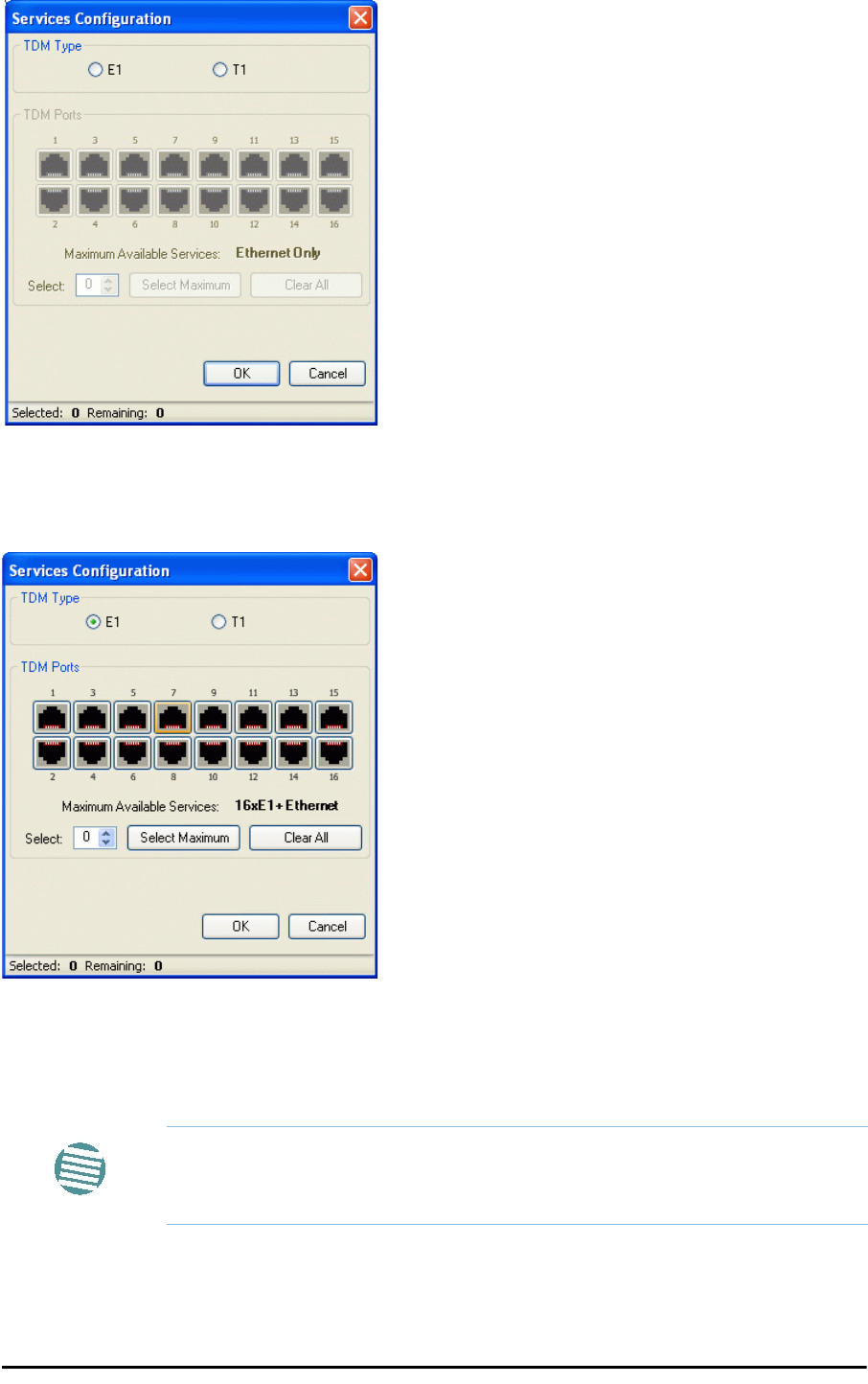
Installation Chapter 5
RADWIN 2000 User Manual Release 2.5.40 5-21
Figure 5-20: TDM Type selection
2. Using the TDM Type radio buttons, choose E1 or T1. You are now able to select the
required service ports:
Figure 5-21: TDM service port selection
3. Use the spin button to choose consecutive service ports, the Select Maximum but-
ton to choose all available ports or click on individual ports to choose them.
Note
• Ethernet is always selected.
• The maximum available services will be reduced in accordance with
actual air interface capacity.
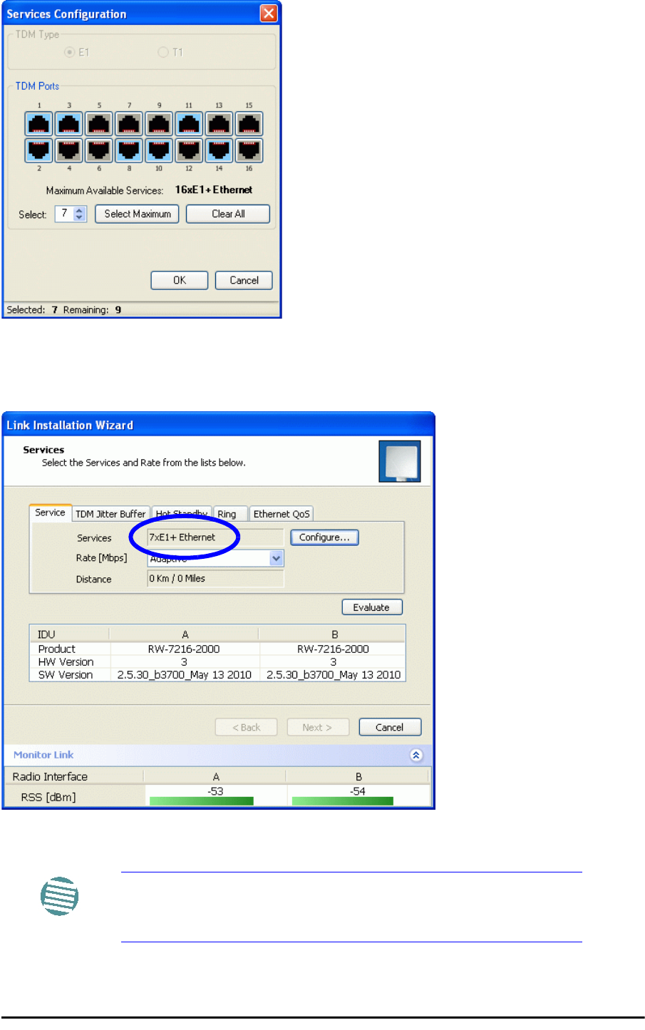
Installation Chapter 5
RADWIN 2000 User Manual Release 2.5.40 5-22
Figure 5-22: TDM Service port selection - seven services selected
4. Click OK. You are returned to the Services and rates dialog of Figure 5-24.
It is updated to reflect your choice.
Figure 5-23: Services and Rates - Services chosen
Note
The selected ports will be enabled for both sides of the link. You
cannot for example, use ports 1, 3, 5, 7 on one side and 2, 4, 6, 8
on the other.
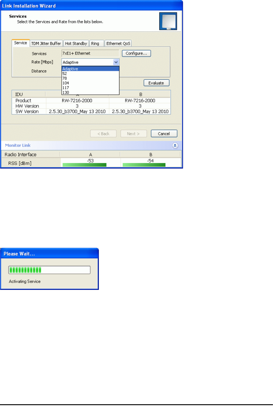
Installation Chapter 5
RADWIN 2000 User Manual Release 2.5.40 5-23
Modulation Rate Selection
You may choose a specific modulation rate or use Adaptive.
Figure 5-24: Services and Rates dialog: Available rates
To choose a modulation rate:
1. Choose Adaptive or one of the available rates.
2. Click Evaluate to continue or click the TDM Jitter Buffer tab to set the TDM Jitter
Buffer (see next section).
The service is activated as show below:
You are returned to the Services and rates dialog of Figure 5-24.
Setting Monitored Hot Standby Mode
If you are not using Hot Standby Mode, you may skip this section.
To install and use the Hot Standby feature, see Chapter 12. The following procedure can be
used to switch links between primary and secondary or to disable the mode.
To set the Hot Standby Mode:
1. Click the Hot Standby tab. The following dialog appears:

Installation Chapter 5
RADWIN 2000 User Manual Release 2.5.40 5-24
Figure 5-25: Choosing Hot Standby Mode
2. Click the radio button to make this link primary or secondary.
Ethernet Ring
To install and use the Ethernet Ring feature, see Chapter 13.
Ethernet QoS
To install and use the Ethernet QoS feature, see Chapter 25.
Setting the TDM Jitter Buffer
To set the TDM Jitter Buffer size:
1. Click the TDM Jitter Buffer tab. The following dialog appears:
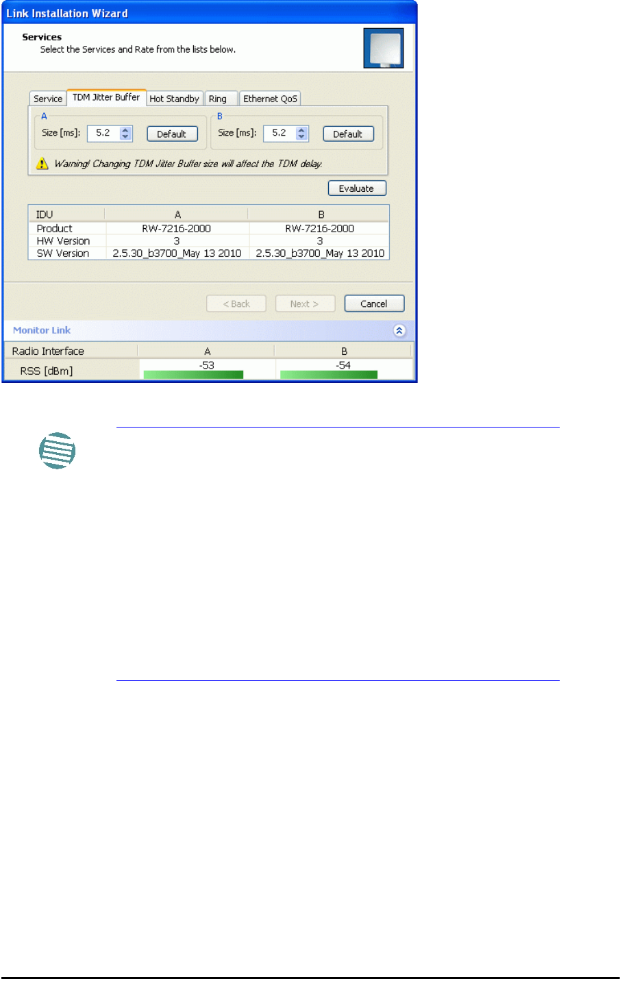
Installation Chapter 5
RADWIN 2000 User Manual Release 2.5.40 5-25
Figure 5-26: TDM Jitter Buffer Configuration
Note
• The receiver jitter buffer for each site can be enlarged,
thereby increasing system resistance to interference (the
larger the jitter buffer, the longer the interference period
that the system will overcome without TDM errors).
• You can also decrease the jitter buffer to decrease the sys-
tem delay.
• The jitter buffer can be configured between 2.0 and 16.0
ms.
• After setting the new value you must evaluate the expected
quality. During the evaluation the TBFR (TDM Block Failure
Ratio)bar is displayed. You select either Next, which per-
forms the change or Back to cancel the change. Notice that
the Jitter Buffer is configured per site.
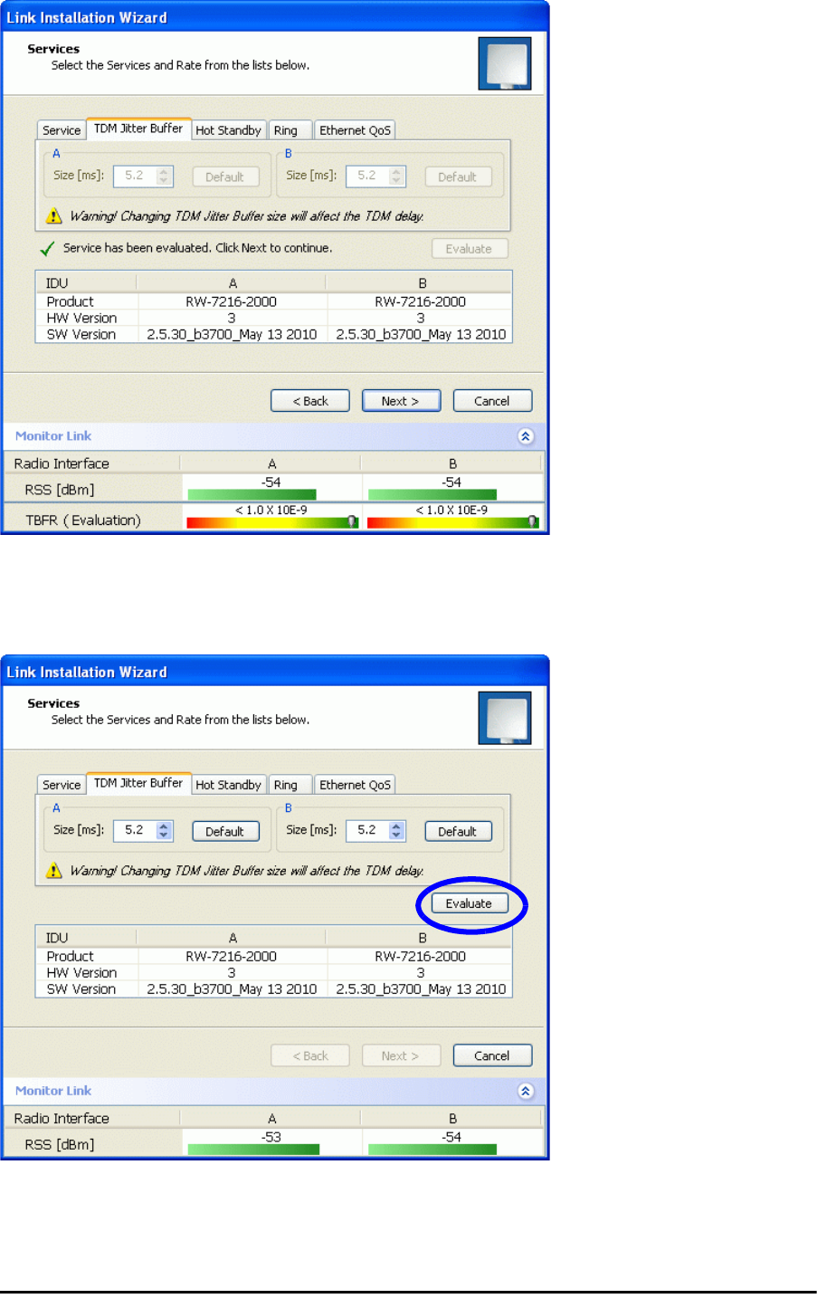
Installation Chapter 5
RADWIN 2000 User Manual Release 2.5.40 5-26
Figure 5-27: TDM Jitter Buffer Configuration - TBFR evaluation bar
2. After setting the jitter buffer size, if grayed out, the Evaluate button is enabled while
both Back and Next are disabled as shown in the next figure:
Figure 5-28: Services and TDM delay set - link ready for evaluation
3. You may make any further changes to the Service Configuration or the Jitter
buffer. When you are satisfied, click the Evaluate.
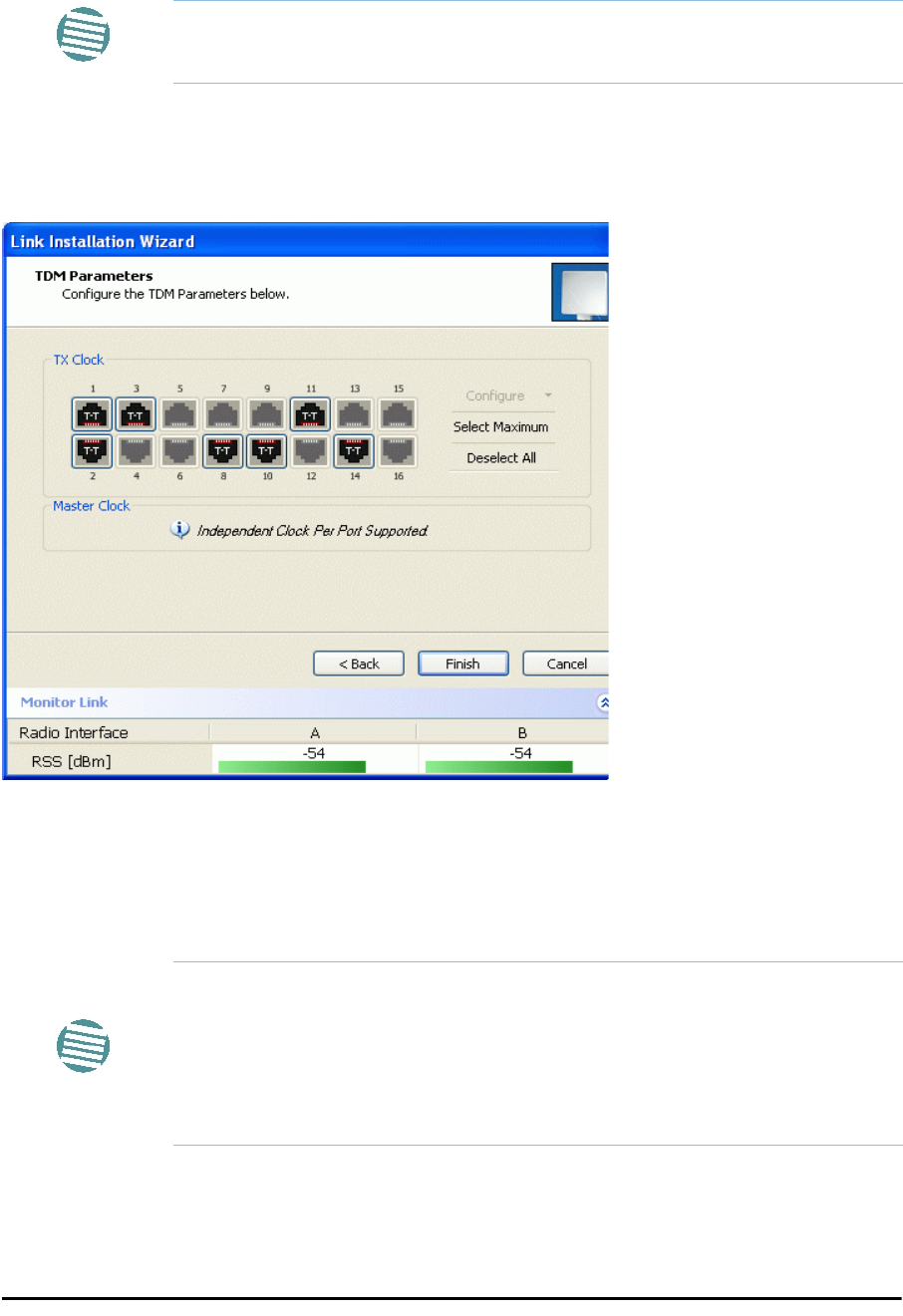
Installation Chapter 5
RADWIN 2000 User Manual Release 2.5.40 5-27
The optimum transmission rate for the selected services is evaluated.
Following a short delay for processing, Back and Next are enabled.
4. Click Next to continue.
Step 7, TDM Clock Configuration
The following dialog is displayed:
Figure 5-29: TDM Parameters Configuration (1)
To configure TDM clock parameters:
1. For any individual port, click it. For the same parameters for all ports, click
the Select Maximum tag.
2. Click Configure. The following drop down list is displayed:
Note
The transmission rates used by RADWIN 2000 are shown in Table 5-3
above.
Note
•Select Maximum will select the maximum number of services that
were configured for the air interface for configuration
•Deselect All unconditionally deselects all of the services for configu-
ration
• Without selecting anything, right-clicking any port will cause the
appearance of the drop down list of Figure 5-30 below
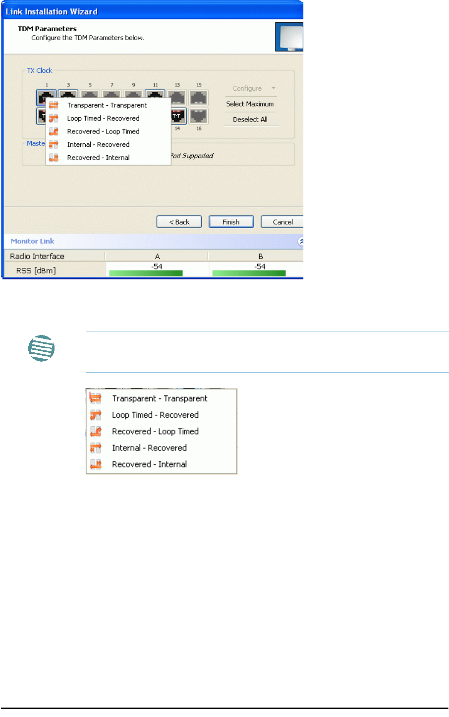
Installation Chapter 5
RADWIN 2000 User Manual Release 2.5.40 5-28
Figure 5-30: TDM Parameters Configuration (2)
3. Click the required parameter. Their meanings are as follows:
Figure 5-31: TDM Parameters
Transparent/Transparent
The clock at Site A regenerates the clock from Site B and
vice versa.
Loop time/Recover
The Site A port receive-clock is used as the transmit-clock
for that port on both sides of the link.
Recover/Loop time
The Site B port receive-clock is used as the transmit-clock
for that port on both sides of the link.
Internal/Recover
Note
Please keep in mind that what follows is
per port
.
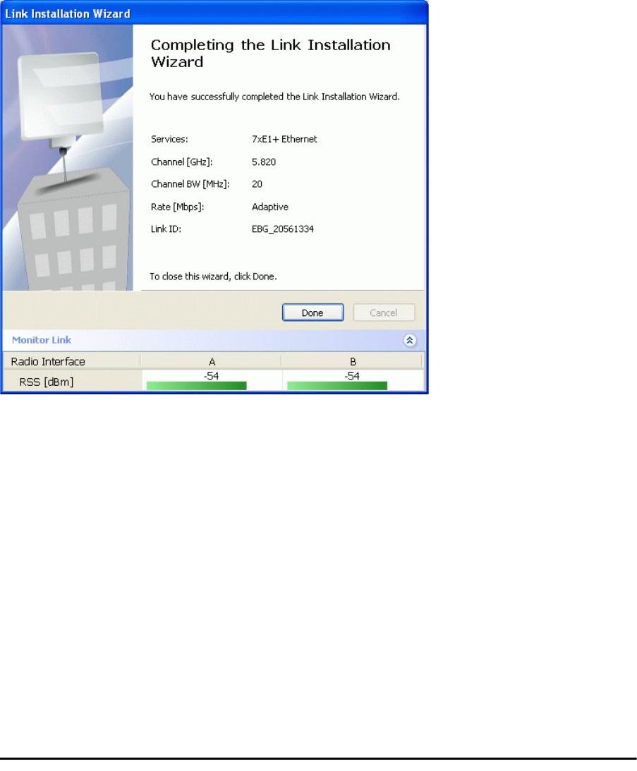
Installation Chapter 5
RADWIN 2000 User Manual Release 2.5.40 5-29
The Site A port uses its internal oscillator to generate its
transmit clock while the Site B port regenerates the clock
received at the Site A port.
Recover/Internal
The Site B port uses its internal oscillator to generate its
transmit clock while the Site A port regenerates the clock
received at the Site B port.
4. Click Finish to complete the wizard.
Step 8, Installation Summary and Exit
Figure 5-32: Installation Wizard Exit Summary
Click Done to return to the main window.
The main window now reflects the installation:
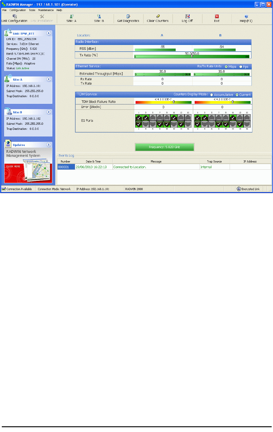
Installation Chapter 5
RADWIN 2000 User Manual Release 2.5.40 5-30
Figure 5-33: Main window of the Manager after installation with loaded trunks
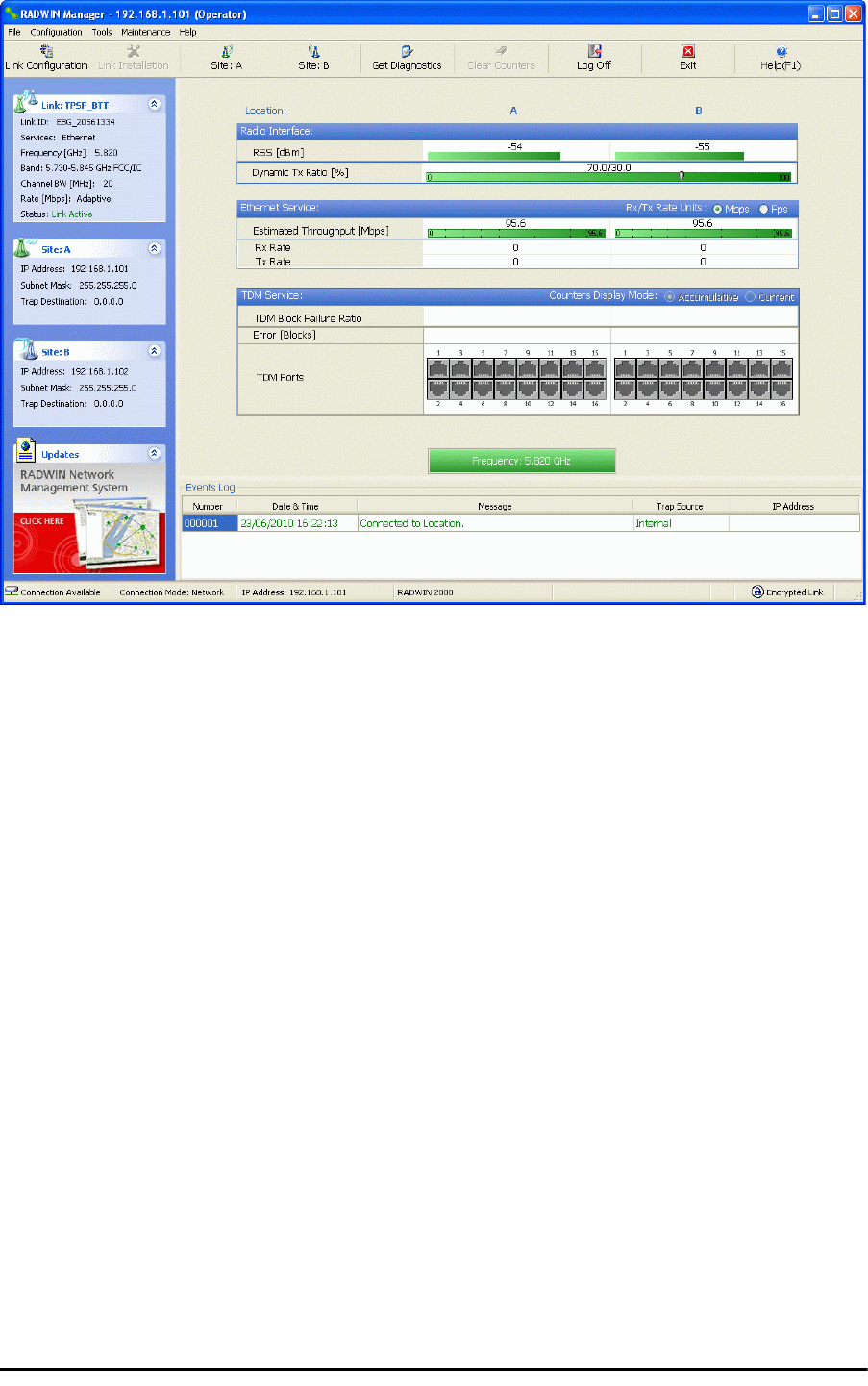
Installation Chapter 5
RADWIN 2000 User Manual Release 2.5.40 5-31
Figure 5-34: Main window of the Manager after installation with asymmetric capacity alloca-
tion - No HSS
Figure 5-34 shows the results of a 70%/30% Transmission ratio on a lone link (no HSS).
Observe that near 100Mbs is available in either direction
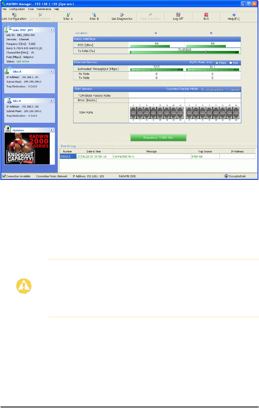
Installation Chapter 5
RADWIN 2000 User Manual Release 2.5.40 5-32
Figure 5-35: Main window of the Manager after installation with asymmetric capacity alloca-
tion - HSS enabled
Figure 5-35 shows the results of a 70%/30% Transmission ratio on a lone link with HSS.
The allocation is “hard”.
To verify the installation:
• Verify that the Received Signal Strength (RSS) is according to expected results as
determined by the Link Budget Calculator.
Caution
Installation mode, as described above, may be re-entered using Site:A or
Site:B and Installation Mode in the Site Configuration dialog. Some
Installation mode functionality may cause a break in, or degrade link
service.
If you can accomplish link changes without affecting the service, always
prefer to use Configuration mode, described in Chapter 7.

RADWIN 2000 User Manual Release 2.5.40 6-1
Chapter 6
The RADWIN Manager:
Main Window
One Manager for all RADWIN Radio Products
The RADWIN Manager application is largely generic to all RADWIN Radio Products.
Functionality differences are minimal according to radio series (WinLink 1000 and RADWIN
2000) capabilities.
The Main Window of the RADWIN Manager
Ensure that the RADWIN Manager is running.
The main window should look similar to that in Figure 6-1:
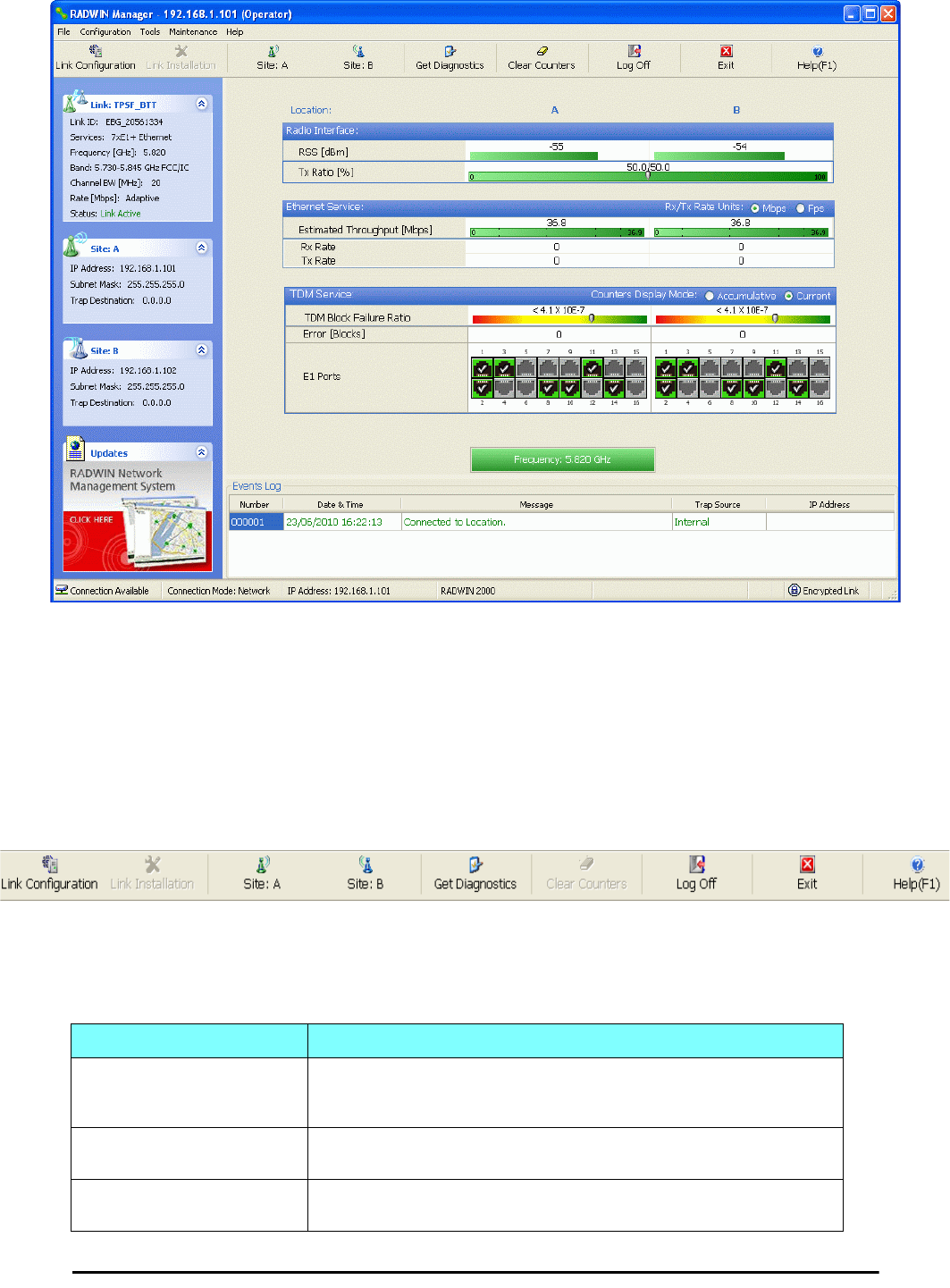
The RADWIN Manager Toolbar Chapter 6
RADWIN 2000 User Manual Release 2.5.40 6-2
Figure 6-1: Main window, Wireless Link is Active
The main window of the RADWIN Manager contains a large amount of information about the
link. Before proceeding to details of link configuration we set out the meaning of each item in
the main window.
The RADWIN Manager Toolbar
In configuration mode, the RADWIN Manager toolbar contains the following buttons:
In Installation mode, Link Configuration is grayed out and Link Installation is open.
The button functions are set out in Table 6-1:
Table 6-1: RADWIN Manager Toolbar
Item Description
Link Configuration Changes configuration parameters of an operating wireless link; assigns text files
for storing alarms, statistics and configuration data. This button is disabled
until a link installation has been completed
Link Installation Performs preliminary configuration of the system. This button is disabled after
the link is installed
Site: <Site 1 name> Opens the Site configuration dialog for Site 1. Same as Configuration | 1
Configure <Site 1 name>

Main Menu Functionality Chapter 6
RADWIN 2000 User Manual Release 2.5.40 6-3
Main Menu Functionality
The main menu contains the following items:
The RADWIN Manager menu functionality is displayed in Table 6-2.
Site: <Site 2 name> Opens the Site configuration dialog for Site 2. Same as Configuration | 2
Configure <Site 2 name>
Get Diagnostics Obtain system information
Clear Counters Clears TDM error blocks counters. Disabled for Ethernet-only link
Log off Closes the current session and logs off RADWIN Manager
Exit Exits RADWIN Manager
Help Opens Help on the use of contextual online help
Table 6-2: RADWIN Manager main menu functionality
Menu level Function Reference
Top +1 +2
File
Log Off Return to log-on dialog. Same as Log
Off button
Exit Exit the RADWIN Manager. Same as
Exit button
Configuration
Link Configuration Run the Configuration Wizard. Not
available in Installation Mode Chapter 7
1 Configure <Site 1
name>
Opens the Site configuration dialog for
Site 1. Has a path to return to
Installation Mode Chapter 8
2 Configure <Site 2
name>
Opens the Site configuration dialog for
Site 2. Has a path to return to
Installation Mode
Link Installation Runs the Installation Wizard. Not
available in Configuration Mode Chapter 5
Table 6-1: RADWIN Manager Toolbar (Continued)
Item Description

Elements of the RADWIN Manager Main Window Chapter 6
RADWIN 2000 User Manual Release 2.5.40 6-4
Elements of the RADWIN Manager Main Window
Link details pane
The Link details pane on the left is split into three sections, which are largely self explanatory.
The top section summarizes information about the link:
Tools
Performance
Monitoring Report On screen and printable
Chapter 9
Active Alarms
1 <Site 1 name> Shows active alarms for <Site 1
name>
2 <Site 2 name> Shows active alarms for <Site 1
name>
Recent Events Displays recent events by site
Software Upgrade Upgrade ODU firmware Chapter 15
Spectrum View Monitor and evaluate spectrum
availability Chapter 23
Change Band
(Installer only) Change the link band Chapter 20
Change Password Change the log-on password dialog page 4-8
Events Log Clear Events Clear local events log page 9-17
Save to File Save events log file
Preferences Local preferences dialog
Maintenance
Clear counters Clear TDM counters
Loopbacks Set TDM loopbacks page 9-4
Estimate Eth.
Throughput
Estimate Ethernet throughput by
transmitting full size frames over the
air for 30 sec page 9-11
Reset 1 <Site 1 name> Reset <Site 1 name> ODU
2 <Site 2 name> Reset <Site 2 name> ODU
Help
RADWIN Manager
Help View help on online help
Link Budget
Calculator Calculator opened in default browser Chapter 21
Get Diagnostics
Information Obtain system information page 9-1
Check for Updates Check for updates from the RADWIN
Web site
About RADWIN
Manager Manager build and system information
Table 6-2: RADWIN Manager main menu functionality (Continued)
Menu level Function Reference
Top +1 +2
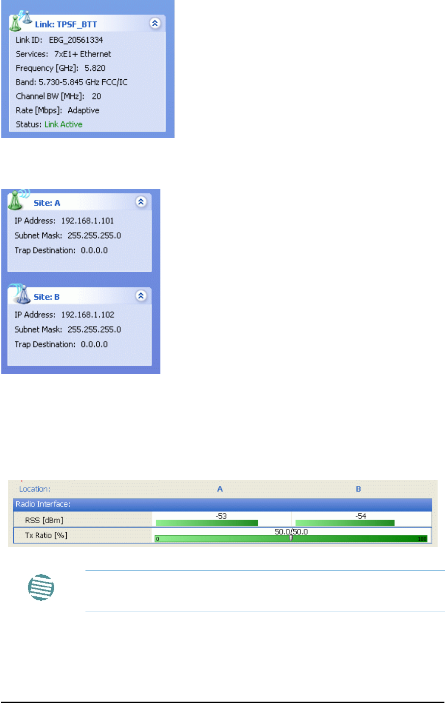
Elements of the RADWIN Manager Main Window Chapter 6
RADWIN 2000 User Manual Release 2.5.40 6-5
For Link status possibilities and color codes, see Table 9-2.
The two lower left panels show basic link site details:
The three fields for each site are user definable. See page 8-7.
The Monitor pane
The monitor pane, is the main source of real time information about link performance at both
link sites. It includes the following panes (top to bottom):
• Radio Interface, Received Signal Strength (RSS) in dBm and Transmission Ratio:
• Ethernet Service:
Note
The Dynamic Tx Ratio bar only appears for model RADWIN 2000 C
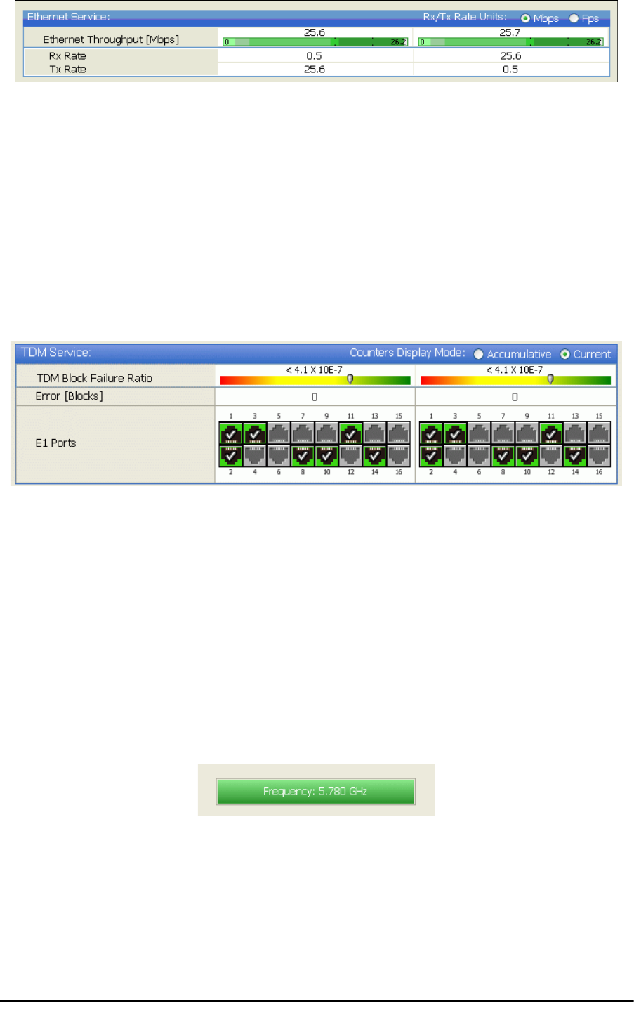
Elements of the RADWIN Manager Main Window Chapter 6
RADWIN 2000 User Manual Release 2.5.40 6-6
•
Estimated Ethernet Throughput:
The numbers are the current calculated
throughputs at each site. The colored bars (with numbers) indicate the maximum
possible throughput having regard for air conditions.
•
Rx and Tx Rates:
The Rx and Tx rates are the receive and transmit rates on the
LAN side of each ODU, not the air side. For a balanced link, the Rx and Tx rates
at the LAN side of Site A will match the Tx and Rx rates at the LAN side of Site B
respectively. In all cases, The LAN side Rx rate shown will be the same as the air
side Tx rate for each individual ODU.
Actual Ethernet traffic received and transmitted rates per site, is in Mbps of Fps,
selectable in the panel title bar.
• TDM Services: IDU-C and new style IDU-E:
• The title bar enables you to switch between Accumulative and Current view.
• Immediately below the title bar is displayed the TDM Block Failure Ratio. It is
zeroed by the Clear Counters button in the tool bar.
• Error block count is shown immediately above the active TDM channels display.
• The color of the TDM ports reflects their current status:
•Green - Operational
• Red - Error: LOS for loss of signal and AIS for Alarm Indi-
cation Signal
• Yellow - Loopback
•Gray - Inactive
• Frequency box: It shows the link frequency. The color of the box indicates the status
•Green is an active link
•Red is an inactive link
•Magenta indicates an authentication or compatibility problem
•Brown indicates severe compatibility problem
Events Log
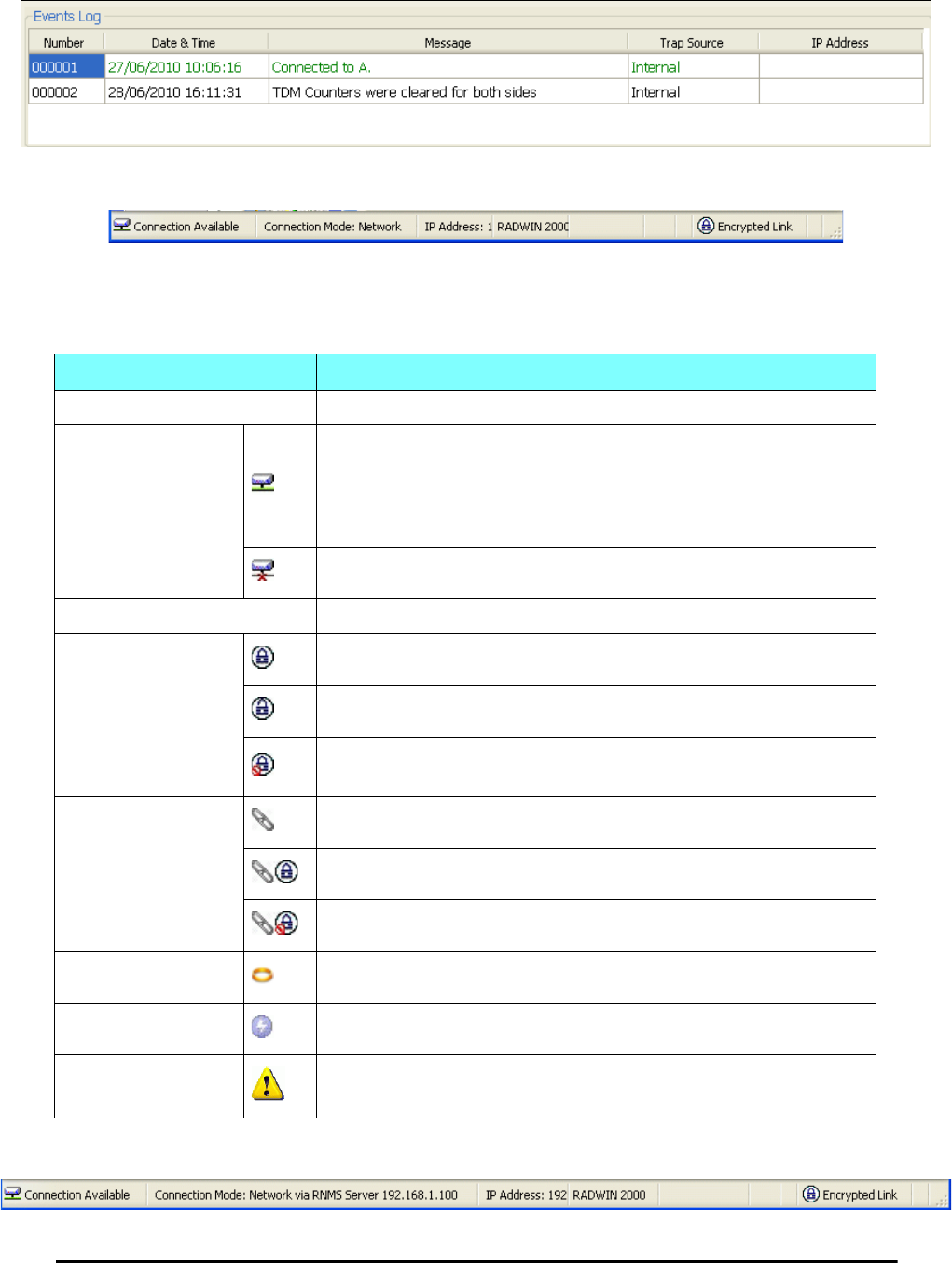
Elements of the RADWIN Manager Main Window Chapter 6
RADWIN 2000 User Manual Release 2.5.40 6-7
The Events Log, stores alarms generated from both sides of the link and is detailed in Chap-
ter 9.
Status Bar
The Status bar, displays the following icons:
RADWIN RNMS users will see an additional field showing the IP address of the RNMS server:
Table 6-3: Status bar indicators
Icon or Label Purpose
Connectivity Shows if RADWIN Manager is communicating with the ODU.
Connection available
Connection mode to the ODU
• Over-the-Air connection - using the IP address of the remote unit.
• Local connection - direct connection to the IDU without using an IP
address.
• Network connection - through a LAN
ODU unreachable
IP Address Log on IP address
Encryption indicator
Normally encrypted link
Unencrypted link - lock open
Link password validation failed. The link is encrypted with default keys.
Service and configuration are unavailable. Change the link password.
Link Lock
Link Lock enabled
Link Lock encrypted
Link Lock mismatch
Ethernet Ring Member
DFS in use
Rescue Alarm In the event of an active alarm, opens alarms dialog

Elements of the RADWIN Manager Main Window Chapter 6
RADWIN 2000 User Manual Release 2.5.40 6-8

RADWIN 2000 User Manual Release 2.5.40 7-1
Chapter 7
Configuring the Link
Overview
This chapter describes the link configuration procedure, which is performed after the installa-
tion of both sides of the RADWIN 2000 link, as set out in Chapter 5.
Link configuration uses a Link Configuration wizard to redefine the configuration parameters
and fine-tune an operational link. Both sides of the link are configured simultaneously.
Link configuration allows you to configure link parameters, which do not lead to sync loss or
require a reset. Some may change service performance, in respect of which, warnings are dis-
played.
For ease of use, the Link Configuration wizard follows the same pattern as Link Installation.
You should therefore be familiar with the content of Chapter 5.
The following parameters are configured using the Link Configuration Wizard:
• System parameters
• Channel settings
• Transmission power and antenna settings
• Service parameters
The Configuration Wizard has seven steps as shown in Table 7-1 below.
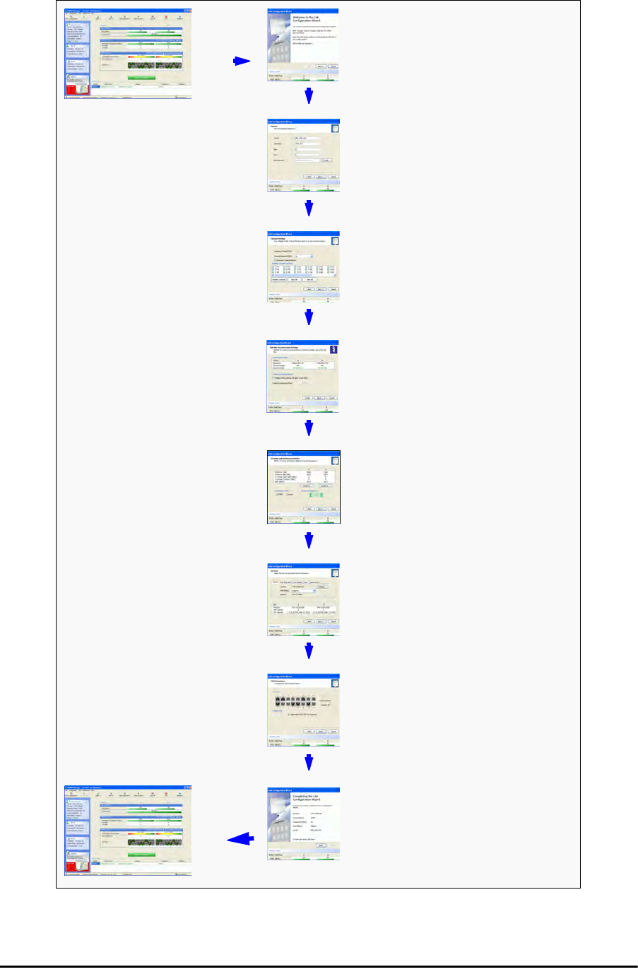
Overview Chapter 7
RADWIN 2000 User Manual Release 2.5.40 7-2
Table 7-1: Link Configuration Wizard
1Wizard welcome
2System parameters
•Link ID
•Site details
3Channel settings - ACS
Configuration
4HSS settings
5Tx Power and antenna
settings, MIMO or
Diversity
6Services - Types,
Adaptive or fixed, Jitter
Buffer, MHS, Ethernet
Ring, QoS
7Set TDM Clock
Parameters
8Wizard summary and
completion
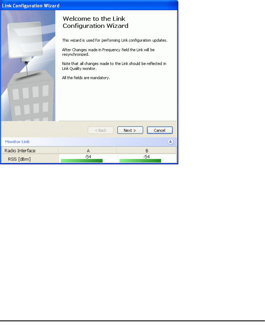
Configuration Chapter 7
RADWIN 2000 User Manual Release 2.5.40 7-3
Configuration
Since configuration functionality is included in the installation, we will briefly review the main
steps and for most part offer references to the corresponding installation step.
Step 1, Start the Wizard
In the tool bar of the RADWIN Manager main window, click the Link Configuration button.
The Link Configuration button is only accessible on a fully installed link as set out in Chapter
5.
The Configuration Wizard opens:
Figure 7-1: Link Configuration Wizard
Click Next to proceed with the configuration procedure.
Step 2, System Parameters
The System dialog box opens:
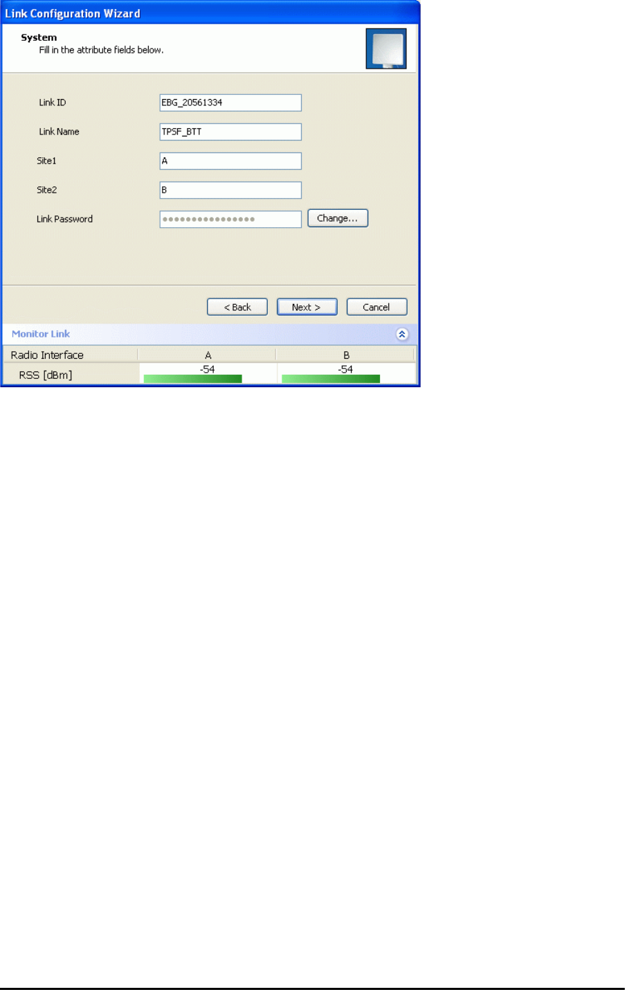
Configuration Chapter 7
RADWIN 2000 User Manual Release 2.5.40 7-4
Figure 7-2: Configuration Wizard, System dialog box
The System attributes may be edited and the Link Password may be changed exactly as in the
corresponding Link Installation step on page 5-5.
Click Next to continue.
Step 3, Channel Settings
Configuring the Channel Settings follows the same pattern as the Installation procedure:
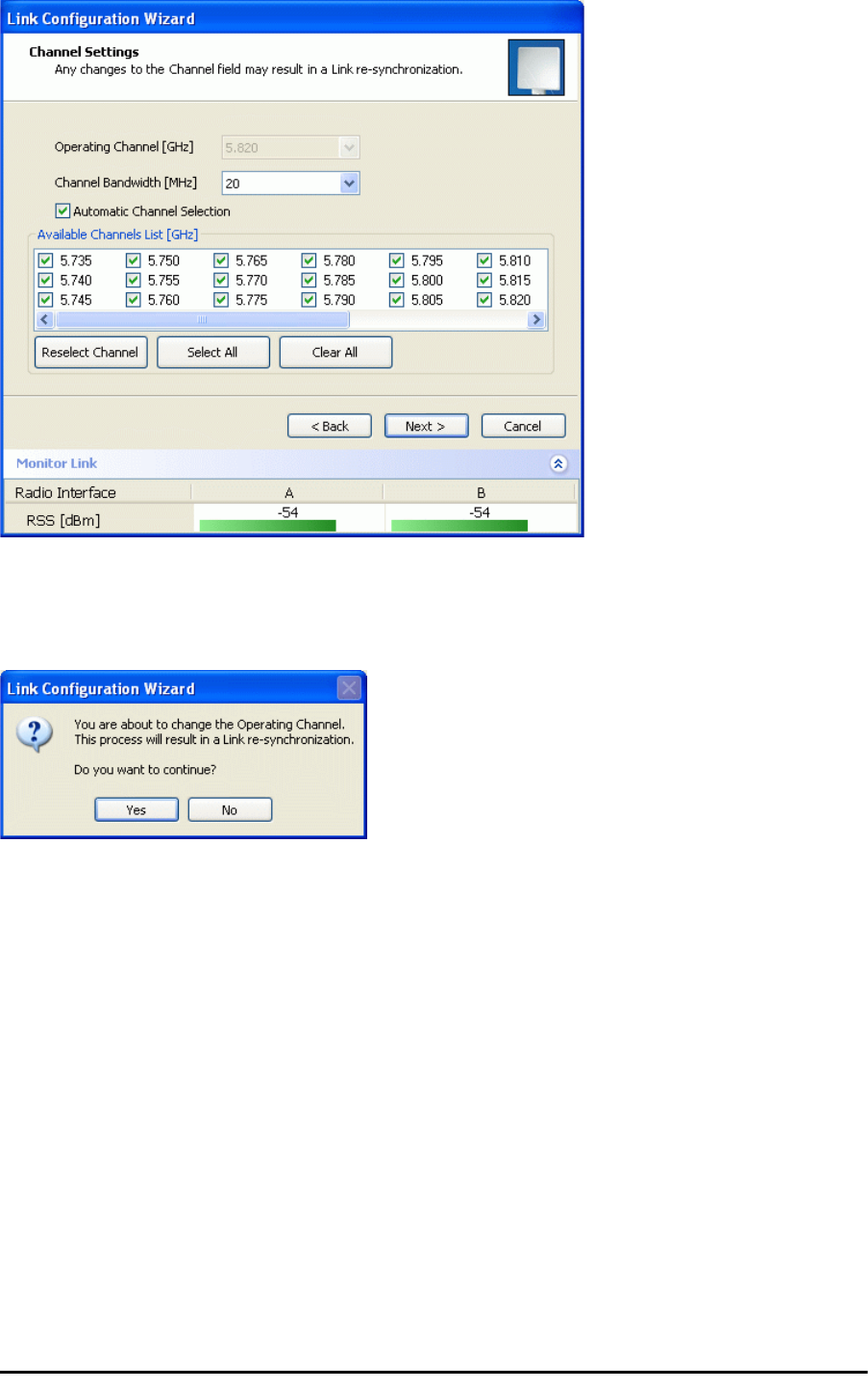
Configuration Chapter 7
RADWIN 2000 User Manual Release 2.5.40 7-5
Figure 7-3: Channel Settings dialog box - Automatic Channel Selection
Notice that the operating channel is grayed out. If you use the Reselect Channel button, to
change it, you will be asked for confirmation:
If you accept, then the system will search for the best operating channel:
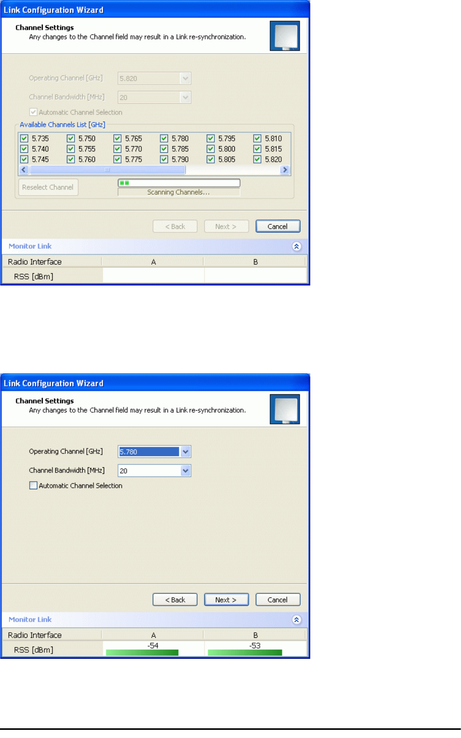
Configuration Chapter 7
RADWIN 2000 User Manual Release 2.5.40 7-6
Figure 7-4: Searching for the best operating channel
The link will return to the status of Figure 7-3 above with a possible change to the operating
channel.
If you work without automatic channel selection, the Channel Settings window looks like this:
Figure 7-5: Channel Settings without automatic channel selection
If you click the Operating Channel drop-down list, the following window appears:
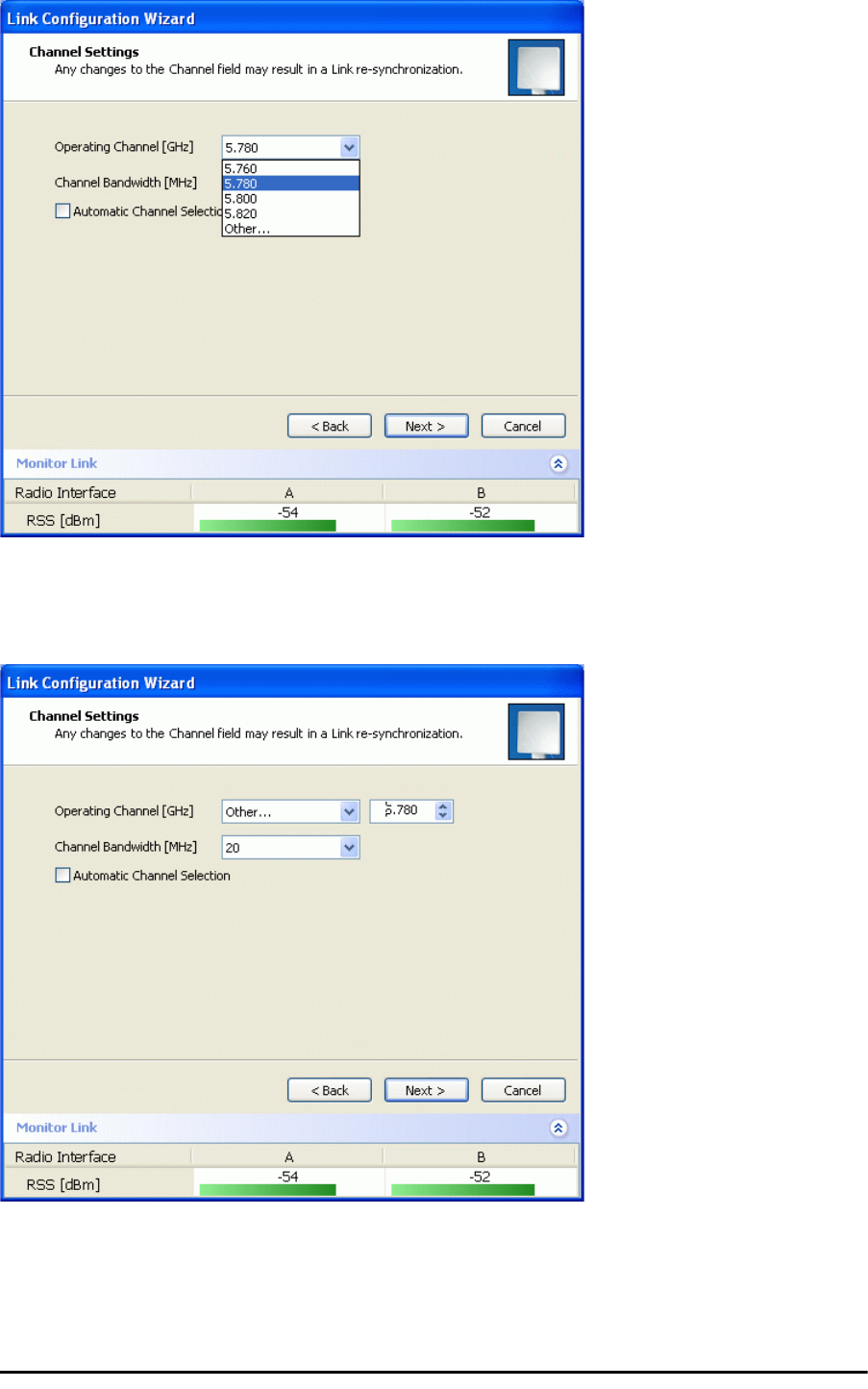
Configuration Chapter 7
RADWIN 2000 User Manual Release 2.5.40 7-7
Figure 7-6: Channel frequency options
Selecting one of the frequencies presented returns you to the status of Figure 7-5 with the
appropriate change. If you choose Other..., the following window opens:
Figure 7-7: Choosing an “Other” Operating Channel frequency
The right hand drop-down list (showing the current Operating Channel) allows you to fine-
tune the frequency in increments of ±5MHz within a range of the operating band, which in
this example is 5.740 - 5.835 GHz.
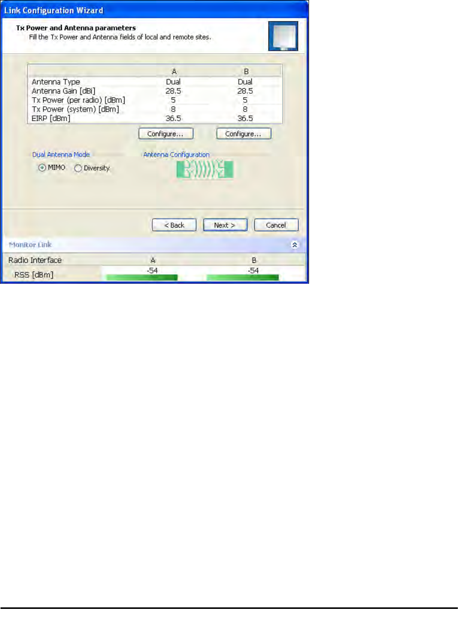
Configuration Chapter 7
RADWIN 2000 User Manual Release 2.5.40 7-8
The Channel Bandwidth may also be changed. The available choices are 10, 20 and 40MHz
depending on regulation (see Appendix A).
When you have completed making your choice, click Next to continue.
Step 4, Tx Power and Antenna Settings
The Tx Power and Antenna Settings window is similar to that for Installation:
Figure 7-8: Transmission Power and Antenna Parameters
As in Installation mode, you need to consider three items:
• Number of antennas at each Link site (1 or 2)
• Tx Power setting for each one
• MIMO or Diversity mode
Changing Number of Antennas and Tx Power
TX Power, Antenna Gain and Cable Loss
If you chose to configure either antenna, you are presented with the following window:
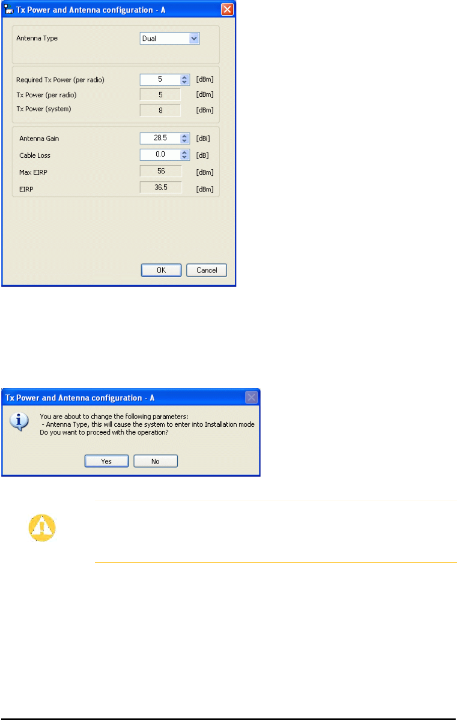
Configuration Chapter 7
RADWIN 2000 User Manual Release 2.5.40 7-9
Figure 7-9: Antenna configuration dialog with opened type selection
(Recall that we are using an unrealistically low Tx power here because our link in a labora-
tory.)
So far, the procedure duplicates the corresponding Installation process. If you choose a differ-
ent antenna type and click OK, you will receive the following cautionary message:
You may also change the Required Tx Power, Antenna Gain and Cable Loss. The procedure is
the same as that set out in the Installation procedure on page 5-13.
Switching Between Single and Dual Antennas
Single/Dual Antenna mode selection works precisely the same way as shown on page 5-20.
If you use this option you will receive a warning similar to this:
Caution
In this context, entering Installation mode causes a service break until it is
restored by running the Installation wizard.
If you are uncertain, do not do this without expert technical assistance.
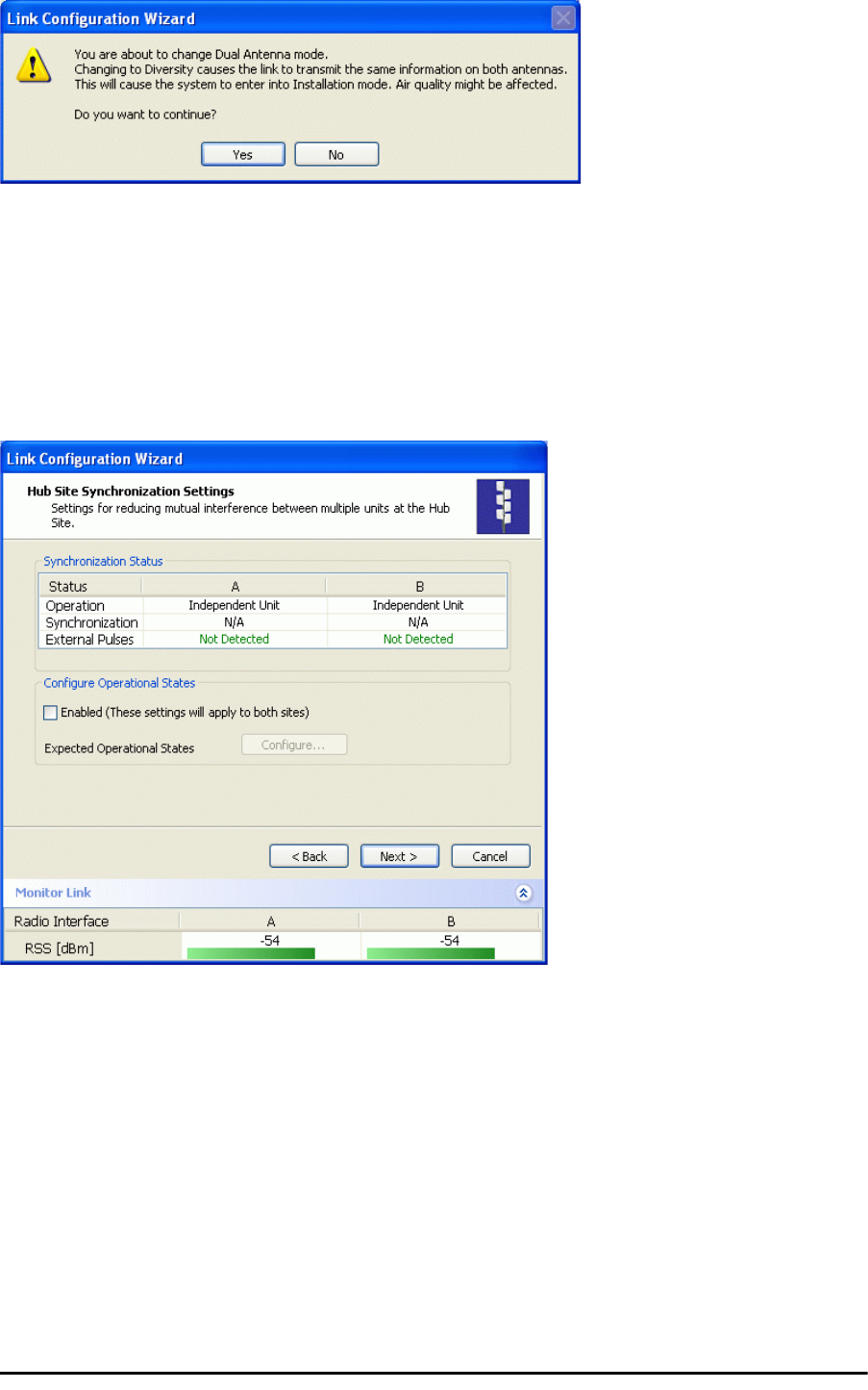
Configuration Chapter 7
RADWIN 2000 User Manual Release 2.5.40 7-10
Switching Between MIMO and Diversity Modes
A similarly worded warning applies to a s switch from Diversity to MIMO mode. The consider-
ations are otherwise no different from those set out in the corresponding Installation step.
When you have completed making your choice, proceed to the Services window.
Step 5, Hub Site Synchronization Settings
Figure 7-10: HSS Settings
The Synchronization Status dialog box displays the current status of each side of the link. See
Chapter 10 for instructions about installing and configuring collocated links. If you do not
require HSS, click Next.
Step 6, Services
Here is the services dialog:
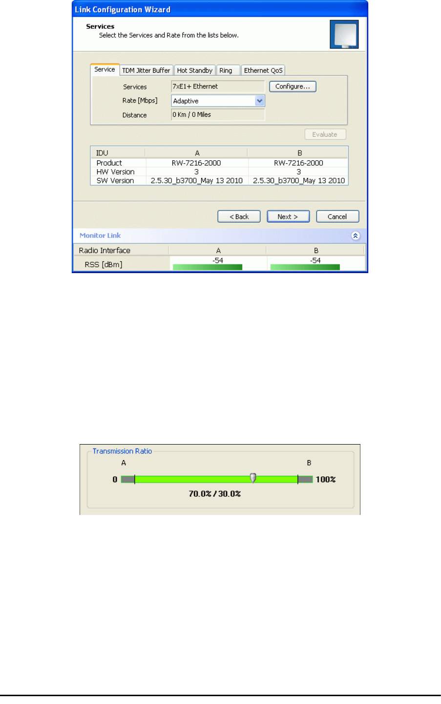
Configuration Chapter 7
RADWIN 2000 User Manual Release 2.5.40 7-11
Figure 7-11: Services and Rates dialog
To choose Services, see the corresponding Installation procedure in Chapter 5.
If you are using a link that -
• is non-collocated
• is Ethernet-only
• uses model RADWIN 2000 C ODUs
then you may use Asymmetric Allocation. You may change the capacity allocation here the
same way as during installation. In place of the IDU box in Figure 7-11, you will see the
Asymmetric Allocation slider:
The procedures for setting the Jitter Buffer and Hot Standby parameters are also the same as
the corresponding procedures in Chapter 5.
Click Next to continue.
Step 7, TDM Clock Configuration
The following dialog is displayed:
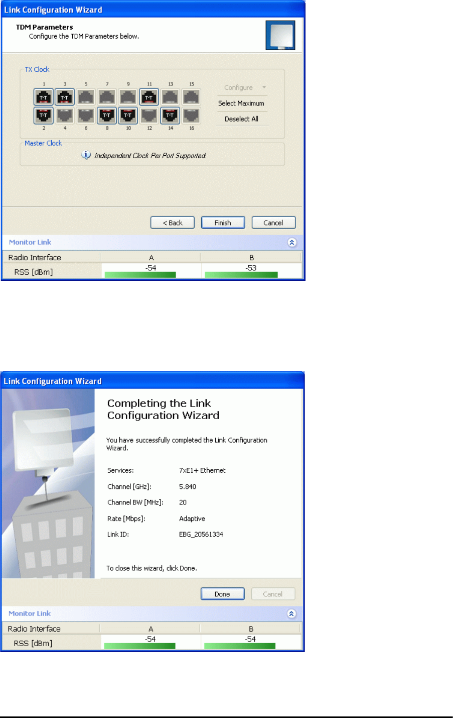
Configuration Chapter 7
RADWIN 2000 User Manual Release 2.5.40 7-12
.
Figure 7-12: TDM Parameters Configuration
To configure the TDM Parameters, see the corresponding procedure in Chapter 5.
Step 8, Configuration Summary and Exit
Figure 7-13: Configuration Wizard Exit Summary
Click Done to return to the main window.
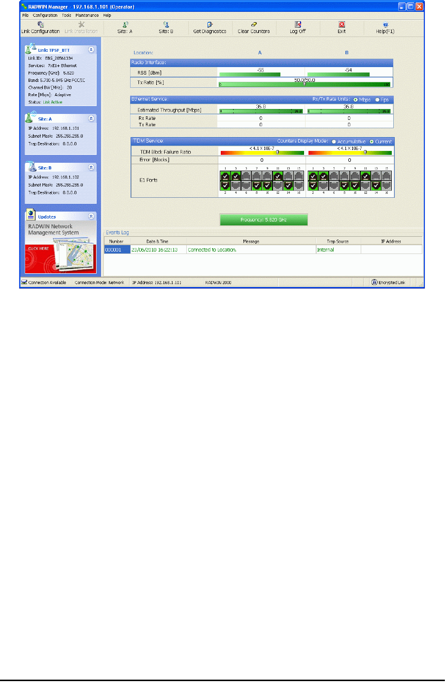
Configuration Chapter 7
RADWIN 2000 User Manual Release 2.5.40 7-13
The main window now reflects the configuration:
Figure 7-14: Main window of the manager after configuration

RADWIN 2000 User Manual Release 2.5.40 8-1
Chapter 8
Site Configuration
The Site Configuration dialog panels are used to configure parameters, which may differ
between both sides of the link.
The parameters configured using the Site Configuration dialog panels include (among oth-
ers):
• System settings
• Air interface - Transmit (Tx) power and antenna
• Hub Site Synchronization status
• Network management including VLAN
• Inventory - link hardware and software model details
• Security settings
• Date and time
• Ethernet service settings
• TDM Hot Standby status
• External alarms settings
• Operations - Revert to factory settings
The Operations dialog offers a “doorway” to jump into installation mode.
The Site Configuration dialog has its own main menu with the following extra functionality:
• Backup ODU software
• Restore ODU software or configuration from a backup file
• Refresh the current panel
• Enable/disable the site ODU buzzer
• Jump back into installation mode keeping current configuration settings
Configuring the Site
Editing the Configuration Parameters by Site
You can edit the configuration parameters for each site individually. The following functions
are available from the left side of the dialog box.

Editing the Configuration Parameters by Site Chapter 8
RADWIN 2000 User Manual Release 2.5.40 8-2
Figure 8-1: Configuration Dialog Box
Functions on the left of the dialog box:
Functions at the top of the dialog box:
System Edit the contact person and location details. View the system
details
Air Interface Change the Tx Power, cable loss, antenna type and settings.
View HSS settings
Management Configure the IP address, Subnet Mask, Default Gateway, Trap
Destination and VLAN
Inventory View the hardware and software inventory (product
identification, versions, MAC address and serial number)
Security Change the Community Values and the Link Password. Set Link
Lock.
Date and Time Set the date and time of the link from an NTP servers or from the
managing computer
Advanced Choose Hub or Bridge ODU mode, IDU aging time, set the
Ethernet ports configuration, set max. information rate, TDM
MHS status, set the external alarm inputs, restore factory
settings, set IDU detection mode.
Backup Save the current ODU software to a file
Restore Restore an ODU’s software or configuration from a backup file
created by the backup facility
Refresh Refresh current panel with latest values
Installation Mode Return to Installation Mode for the entire link.
Selecting the Mute check box before clicking the Install Mode
button mutes the Beeper.
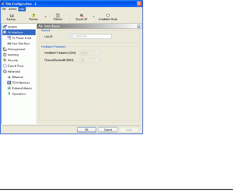
Viewing System Details Chapter 8
RADWIN 2000 User Manual Release 2.5.40 8-3
To edit the Configuration Parameters:
1. Click the required site button on the main tool bar of the RADWIN Manager
OR
Click Configuration from the main menu and choose a site to configure.
The Configuration dialog box opens (see Figure 8-1 above).
2. Choose the appropriate item in the left hand list to open a dialog box.
3. Click Apply to save changes.
In subsequent instructions, we will simply say “Choose a site to configure” on the under-
standing that the foregoing procedure is implied.
Viewing System Details
This is the first window displayed - as depicted above. You can edit the contact details and
site names.
Viewing Air Interface Details
Click the Air Interface item in the left hand list. A window similar to the following appears:
Figure 8-2: Air interface details
Changing the Transmit Power
Each site can have a different Tx Power level.
Buzzer Mutes the alignment tone in installation mode. Reactivate the
beeper during alignment.
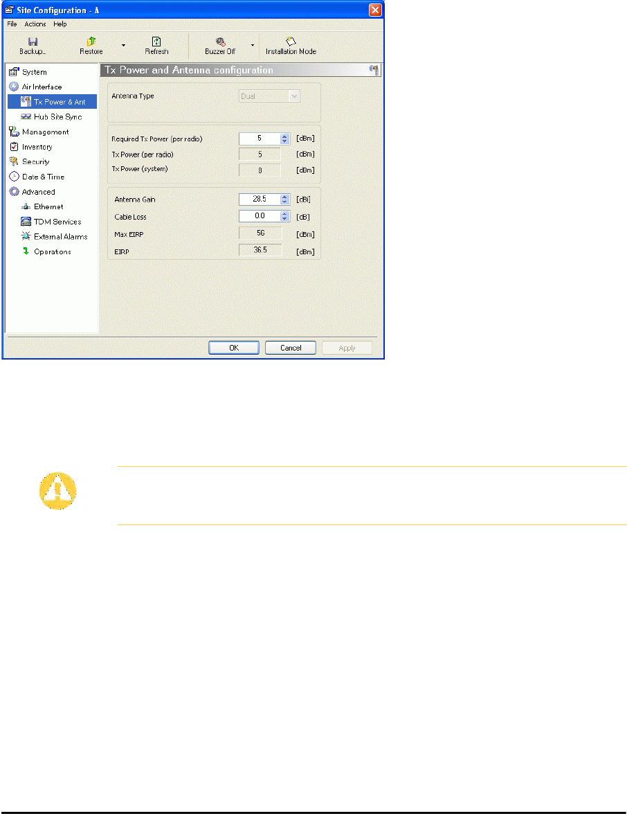
Hub Site Sync Chapter 8
RADWIN 2000 User Manual Release 2.5.40 8-4
To change the Transmit Power:
1. Choose a site to configure.
The Configuration dialog box opens.
2. Choose Air Interface (see Figure 8-3).
3. Choose the required Transmit (Tx) Power Level.
4. Click Apply to save the changes.
Figure 8-3: Changing the Transmit Power
For detailed explanation about the relationship between these parameters, see page 5-13 to
5-21.
Hub Site Sync
Here you can view the HSS status:
Caution
Changing the Tx Power will affect service quality. The same considerations
apply here as were noted in the Installation procedure on page 5-17.
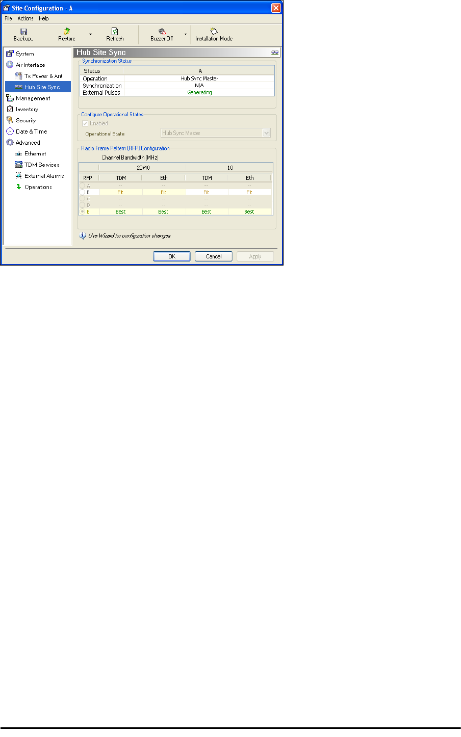
Site Management: IP Address, VLAN and Protocol Chapter 8
RADWIN 2000 User Manual Release 2.5.40 8-5
Figure 8-4: HSS Status
Site Management: IP Address, VLAN and Protocol
Configuring the ODU Address
Each site must be configured separately. For an over-the air configuration, first configure site
B then site A so as to avoid lockout. See Chapter 19 for detailed instructions about the best
way to do this on-site.
See Chapter 14 for further details about VLAN Functionality for RADWIN 2000.
To define the Management Addresses:
1. Choose a site to configure.
The Configuration dialog box opens:
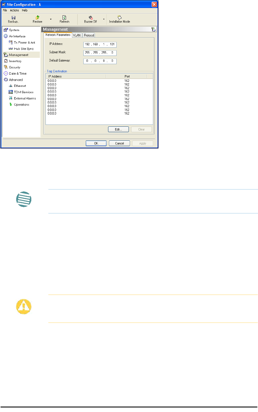
Configuring VLAN Settings Chapter 8
RADWIN 2000 User Manual Release 2.5.40 8-6
Figure 8-5: Management Addresses - Site Configuration dialog box
5. Choose Management.
6. Enter the IP address of the ODU in the IP Address field.
7. Enter the Subnet Mask.
8. Enter the Default Gateway.
9. Enter the Trap Destination. This could be the IP address of the managing computer.
The events log will be stored at this address.
10. Click Apply to save the changes.
Configuring VLAN Settings
VLAN Management enables separation of user traffic from management traffic whenever such
separation is required. It is recommended that both sides of the link be configured with differ-
ent VLAN IDs for management traffic. (This reduces your chances of accidentally locking
yourself out of the link.)
To enable VLAN management:
1. Click Configuration from the main menu.
Note
If performing configuration from the RADWIN Manager, the IP address is
that entered from the Login window.
Caution
VLAN IDs are used by RADWIN products in three separate contexts:
Management VLAN, Traffic VLAN and Ethernet Ring. It is recommended that
you use different VLAN IDs for each context.
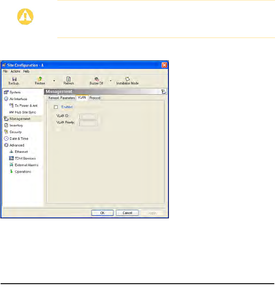
Lost or forgotten VLAN ID Chapter 8
RADWIN 2000 User Manual Release 2.5.40 8-7
2. Choose a site to configure. If you are configuring both sites, choose site B first to
avoid locking yourself out.
3. Choose Management.
4. Open the VLAN tab.
5. Check the Enabled box.
6. Enter a VLAN ID. Its value should be between 1 and 4094.
After entering the VLAN ID, only packets with the specified VLAN ID are processed
for management purposes by the ODU. This includes all the protocols supported by
the ODU (ICMP, SNMP, TELNET and NTP). The VLAN priority is used for the traffic
sent from the ODU to the managing computer. Using VLAN for management traffic
affects all types of management connections (local, network and over the air).
7. Enter a Priority number between 0 and 7.
8. Change the VLAN ID and Priority of the managing computer NIC to be the same as
those of steps 6 and 7 respectively.
9. Click Apply or OK.
Figure 8-6: Configuring management traffic VLAN Settings
Lost or forgotten VLAN ID
If the VLAN ID is forgotten or there is no VLAN traffic connected to the ODU, then reset the
relevant ODU.
Caution
Changing this parameter causes the RADWIN Manager to immediately
disconnect. To avoid inconvenience, you should verify the change by
setting the VLAN only to one ODU, and only after verifying proper
management operation, change the other ODU VLAN setting.
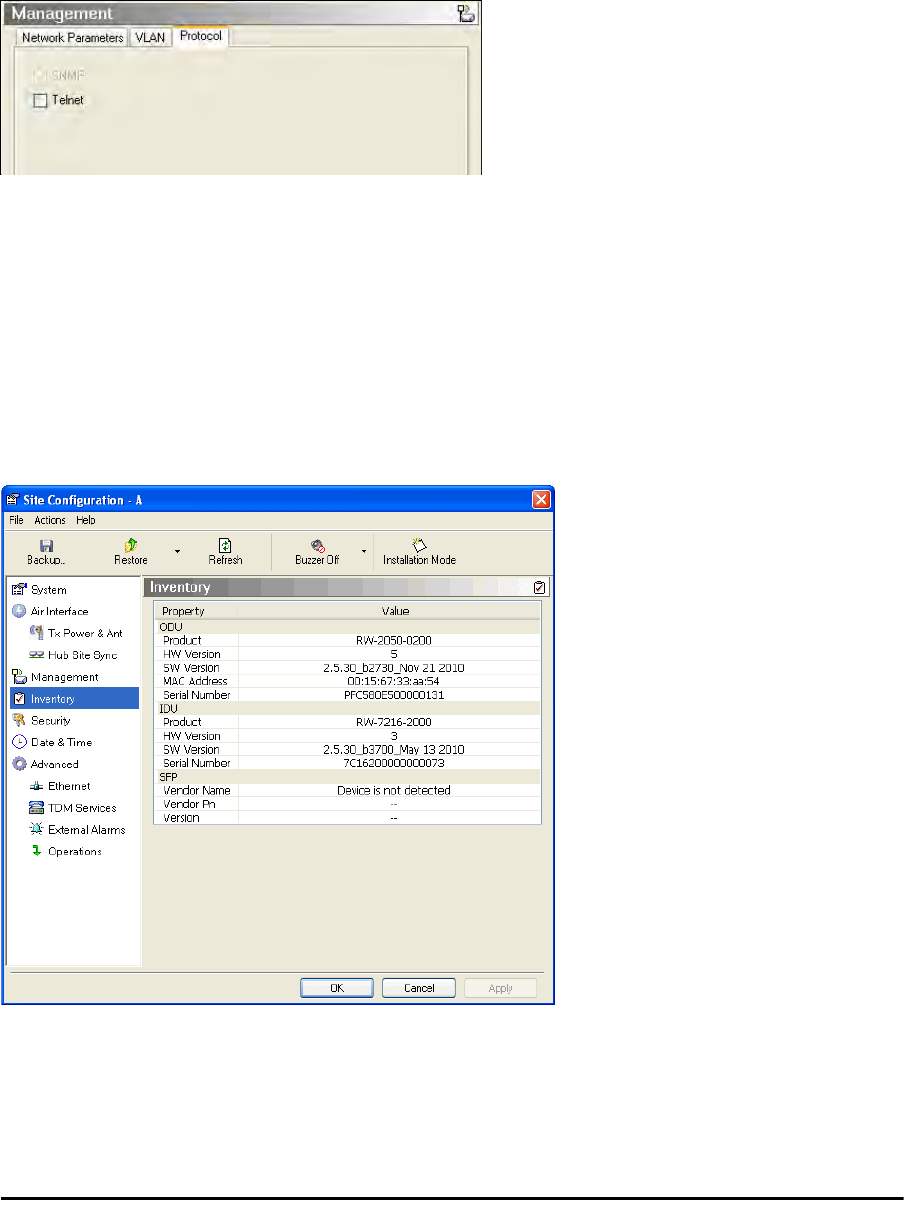
Enable / Disable Telnet Access Chapter 8
RADWIN 2000 User Manual Release 2.5.40 8-8
During the first two minutes of connection, the ODU uses management packets both with and
without VLAN. You may use this period to reconfigure the VLAN ID and priority.
Enable / Disable Telnet Access
For a link managed in a network, direct access to an ODU using Telnet is considered to be a
security breach. Telnet access may be enabled or disabled by clicking the Protocol tab and
enabling/disabling Telnet access using the Telnet check-box:
Figure 8-7: Enable/Disable Telnet Access
Displaying the Inventory
To view the inventory data
1. Choose a site from the main menu.
The Configuration dialog box opens.
2. Choose Inventory.
Figure 8-8: Inventory window
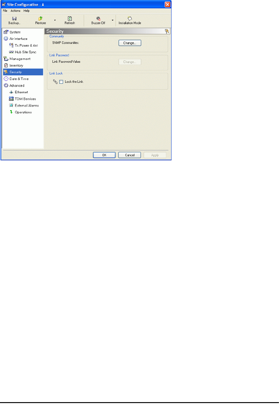
Security Features Chapter 8
RADWIN 2000 User Manual Release 2.5.40 8-9
Security Features
The Security dialog enables you to change the Link Password and the SNMP Community
strings and use the Link Lock feature:
Figure 8-9: Available security features
Changing the Link Password
This item is only available when the link is down. Otherwise, it works the same way as the
corresponding item on page 5-8.
RADWIN Manager Community Strings
The ODU communicates with the RADWIN Manager using SNMPv1 protocol. The protocol
defines three types of communities:
•Read-Only for retrieving information from the ODU
•Read-Write to configure and control the ODU
•Trap used by the ODU to issue traps.
The Community string must be entered at log on. The user must know the password and the
correct Community string to gain access to the system. A user may have read-only privileges.
It is not possible to manage the ODU if the read-write or the read Community values are for-
gotten. A new Community value may be obtained from RADWIN Customer Support for the
purpose of setting new Community. You must also have available the serial number or the
MAC address of the ODU.
The read-write Community strings and read-only Community strings have a minimum of five
alphanumeric characters. (bru1 and bru4097 are not permitted). Changing the trap Com-
munity is optional and is done by clicking the check box.
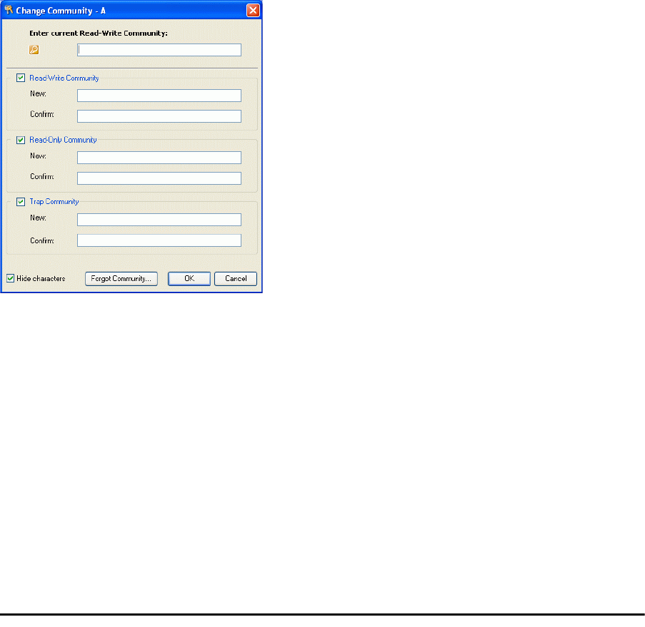
RADWIN Manager Community Strings Chapter 8
RADWIN 2000 User Manual Release 2.5.40 8-10
Editing Community Strings
The Community change dialog box is available from the Configuration | Security tab. Both
read-write and read-only communities must be defined.
On logging on for the first time, use the following as the current Community:
• For Read-Write Community, use
netman
.
• For Read-Only Community, use
public
.
• For Trap Community, use
public
To change a Community string:
1. From the Configuration dialog box, choose the Security tab.
2. Type the current read-write Community (default is
netman
).
3. Choose the communities to be changed by clicking the check box.
4. Type the new Community string and re-type to confirm. A community string must
contain at least five and no more than 32 characters excluding SPACE, TAB, and any
of “>#@|*?;."
5. Click OK to save.
Figure 8-10: Changing the Community String
Forgotten Community string
If the read-write Community string is unknown, an alternative Community key can be used.
The alternative Community key is unique per ODU and can be used only to change the Com-
munity strings. The alternative Community key is supplied with the product, and should be
kept in a safe place.
If both the read-write Community and the alternative Community key are unavailable, then
an alternative Community key can be obtained from RADWIN Customer Support using the
ODU serial number or MAC address. The serial number is located on the product label. The
serial number and the MAC address are displayed in the Site Configuration inventory tab.
When you have the alternative Community key, click the Forgot Community button and
enter the Alternative Community key (Figure 8-11). Then change the read-write Community
string.

Link Lock Security Feature Chapter 8
RADWIN 2000 User Manual Release 2.5.40 8-11
Figure 8-11: Alternative Community Dialog box
Link Lock Security Feature
Link Lock is a part of RADWIN’s security concept intended to meet a form of abuse
encountered in the field. It is designed to prevent the situation where a remote ODU
can be stolen and used as a “pirate” link to steal services or information. The Link
Lock feature actually locks the local ODU to be synchronized ONLY to specific remote
ODU. It is a
site oriented
feature.
The lock can only be set from a live link. It is based on MAC authentication and is site
oriented and activated on a per ODU basis. For example, if you lock the Site B ODU to
the Site A ODU, you must still lock the Site A ODU to the Site B ODU to ensure
complete two way locking.
Link Lock can only be removed when the link is unsynchronized. In such a case, an
alarm is raised by the RADWIN Manager.
To enable Link Lock:
1. Click Site A on the main tool bar.
2. Choose the Security tab. The following window is displayed:
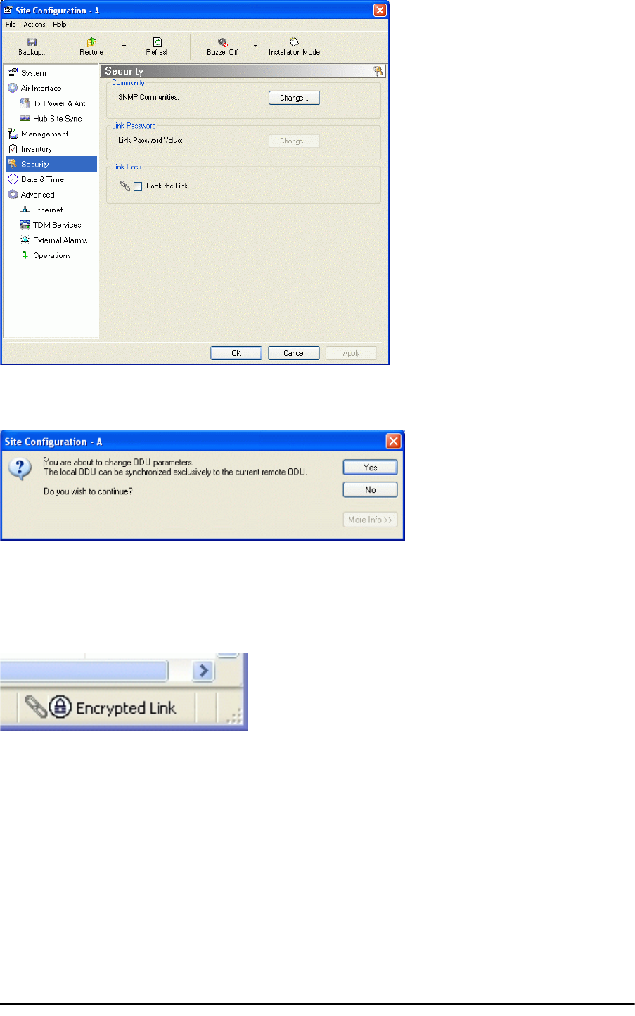
Link Lock Security Feature Chapter 8
RADWIN 2000 User Manual Release 2.5.40 8-12
3. Click the Link Lock check-box and then OK. You are asked to confirm the
lock:
4. Click the Yes button and you are returned to the main window of the
RADWIN Manager.
Observe that a link icon is now displayed in the status bar on the bottom right of the
RADWIN Manager window.
The link to the remote unit is now locked. If you repeat steps 1 and 2 above, the
Security screen will look like this:

Setting the Date and Time Chapter 8
RADWIN 2000 User Manual Release 2.5.40 8-13
The Link Lock check-box is now unavailable.
5. If required, repeat the procedure for Site B.
Setting the Date and Time
The ODU maintains a date and time. The date and time should be synchronized with any Net-
work Time Protocol (NTP) version 3 compatible server.
During power-up the ODU attempts to configure the initial date and time using an NTP Server.
If the server IP address is not configured or is not reachable, a default time is set.
When configuring the NTP Server IP address, you should also configure the offset from the
Universal Coordinated Time (UTC). If there is no server available, you can either set the date
and time, or you can set it to use the date and time from the managing computer. Note that
manual setting is not recommended since it will be overridden by a reset, power up, or syn-
chronization with an NTP Server.
Note
To revert the Link Lock status to unlocked, power down each ODU
in turn. Use the above procedure to uncheck the Link Lock status
box for the live ODU.
A simple ODU reset at either end will restore the link to its previous
locked or unlocked state.
Note
The NTP uses UDP port 123. If a firewall is configured between the ODU
and the NTP Server this port must be opened.
It can take up to 8 minutes for the NTP to synchronize the ODU date and
time.
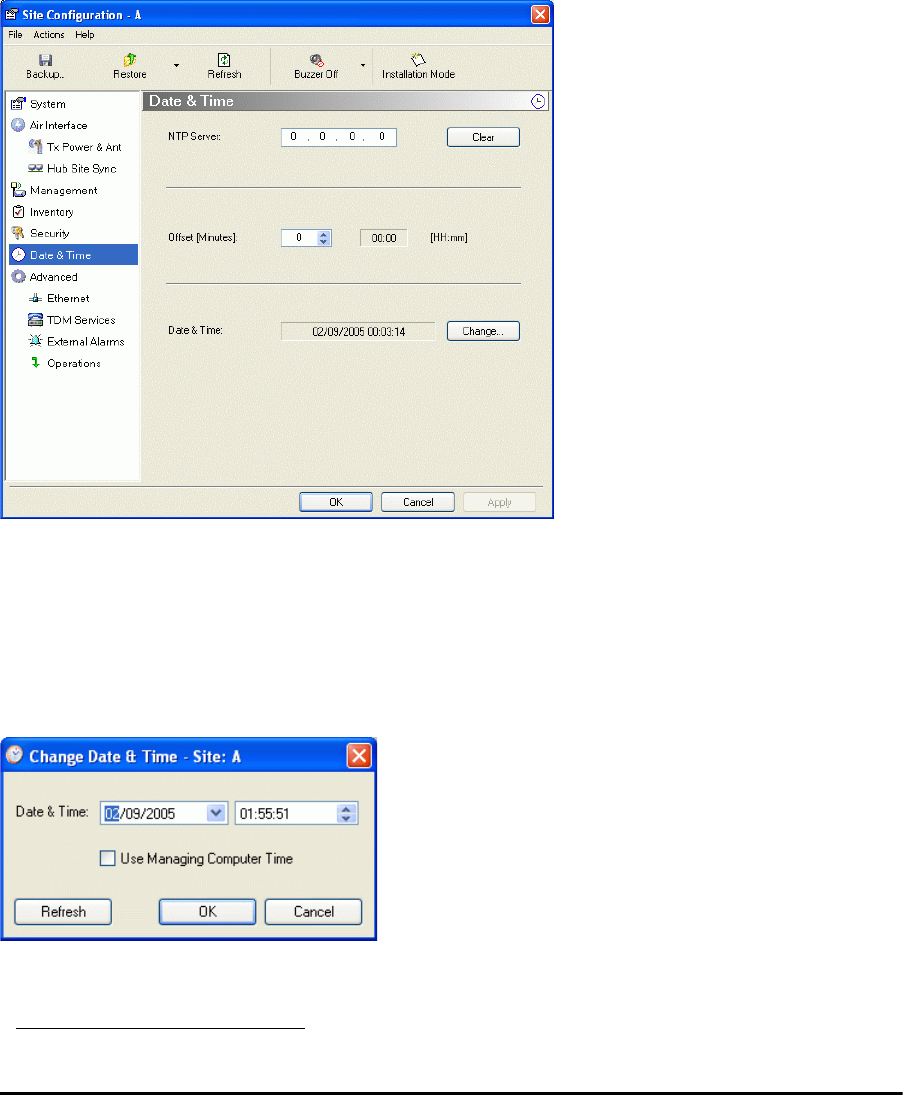
Setting the Date and Time Chapter 8
RADWIN 2000 User Manual Release 2.5.40 8-14
To set the date and time:
1. Determine the IP address of the NTP server to be used.
2. Test it for connectivity using the command (Windows XP), for example:
w32tm /stripchart /computer:216.218.192.202
You should get a continuous response of times, each a few seconds apart.
3. Choose a site to configure.
The Configuration dialog box opens.
4. Choose Date & Time:
Figure 8-12: Date and Time Configuration
5. If entering an IP address for the NTP Server, click Clear, and then enter the new
address.
6. Set your site Offset value in minutes ahead or behind GMT1.
7. To manually set the date and time, click Change and edit the new values.
Figure 8-13: Change Date and Time
If you used an NTP Server, you will see a window like this:
1. Greenwich Mean Time

Ethernet Properties Chapter 8
RADWIN 2000 User Manual Release 2.5.40 8-15
Figure 8-14: Date and Time configured from an NTP Server
8. Click OK to return to the Configuration dialog.
Ethernet Properties
Configuring the Bridge
Bridge configuration is required in various network topologies, such as protection (Ethernet
1+1) and ring applications. The bridge configuration parameters are located under the
Advanced tab of the Site Configuration dialog box:
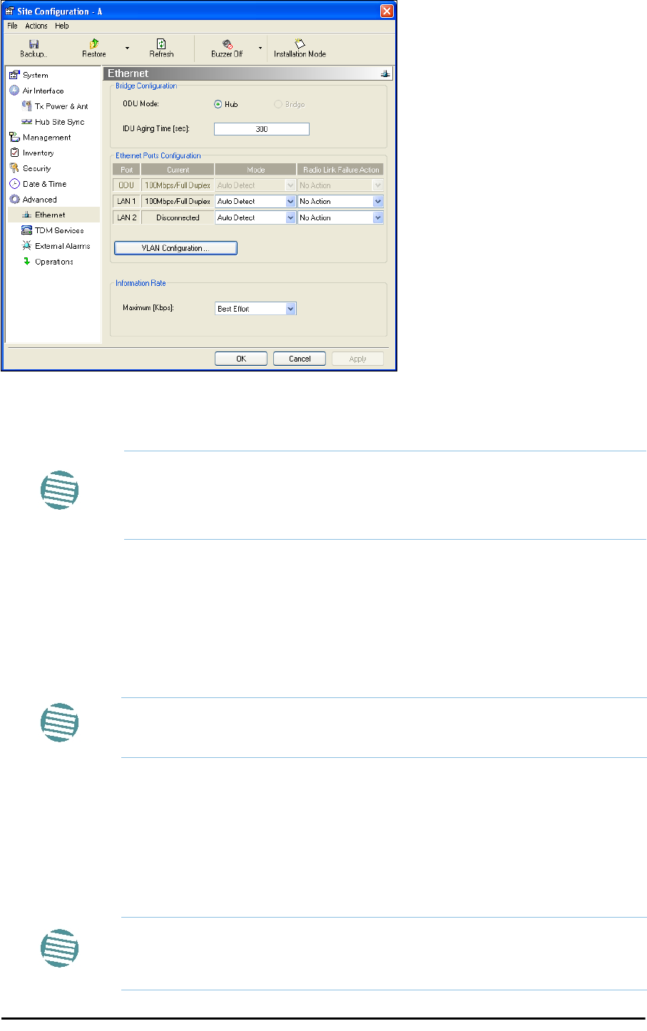
Configuring the Bridge Chapter 8
RADWIN 2000 User Manual Release 2.5.40 8-16
Figure 8-15: Bridge, VLAN and MIR Configuration
ODU Mode
This parameter controls the ODU mode with two optional values:
• Hub Mode - in Hub mode the ODU transparently forwards all packets over the wireless
link.
• Bridge Mode - In Bridge mode the ODU performs both learning and aging, forwarding
only relevant packets over the wireless link. The aging time of the ODU is fixed at 300
seconds.
IDU Aging time
This parameter controls the IDU aging time.
The aging time parameter controls the time after which each MAC address is dropped from
the MAC address learning table.
The default value is 300 seconds.
Note
RADWIN 2000 C-Series ODU products work in Hub mode only. The bridge
capability is built in to the IDU-C (it is not configurable). If an IDU-C is
connected to an RADWIN 2000 C ODU, then the IDU-C performs the
bridging.
Note
Changing these modes requires system reset.
Note
• Any change to these parameters is effective immediately.
• Each side of the link can be configured separately, with different
aging times.

Configuring Ethernet Ports Mode Chapter 8
RADWIN 2000 User Manual Release 2.5.40 8-17
The following table shows the appropriate configuration for several common scenarios. Both
link sites must be configured with the same parameter:
Configuring Ethernet Ports Mode
The ODU Ethernet port is configured to auto-detect by default and may not be changed.
The ODU Ethernet port mode is configurable for line speed (10/100BaseT) and duplex mode
(half or full duplex).
An Auto Detect feature is provided, whereby the line speed and duplex mode are detected
automatically using auto-negotiation. Use manual configuration when attached external
equipment does not support auto-negotiation. The default setting is Auto Detect.
To configure the Ethernet Mode:
1. From the Configuration menu, choose the site to configure.
The Site Configuration dialog box opens.
2. Click Advanced | Ethernet.
3. In the Ethernet Ports Configuration pane, use the drop-down menu to choose the
configuration.
4. Click Apply to save the changes.
VLAN Tagging for Ethernet Service: Configuration
If you are using a PoE device, this feature is unavailable. You may skip this section.
Table 8-1: ODU mode configuration for common scenarios
Scenario ODU
Mode IDU Aging
Time
Standard (default) Configuration for Ethernet
Applications Bridge 300 sec
Rapid network topology changes where fast
aging is required Hub 1 sec
Caution
You should not reconfigure the port that is used for the managing computer
connection, since a wrong configuration can cause a management
disconnection or Ethernet services interruption.
Note
It is possible to close the Ethernet service by disconnecting the Ethernet
port.
If you close the port, you may subsequently be unable to access the
device. If this should occur, a workaround is as follows:
• Connect the system from the remote site
• Connect via other Ethernet port (of the IDU)
• Power down the equipment and connect immediately after power
up (the fastest way is to enter install mode)
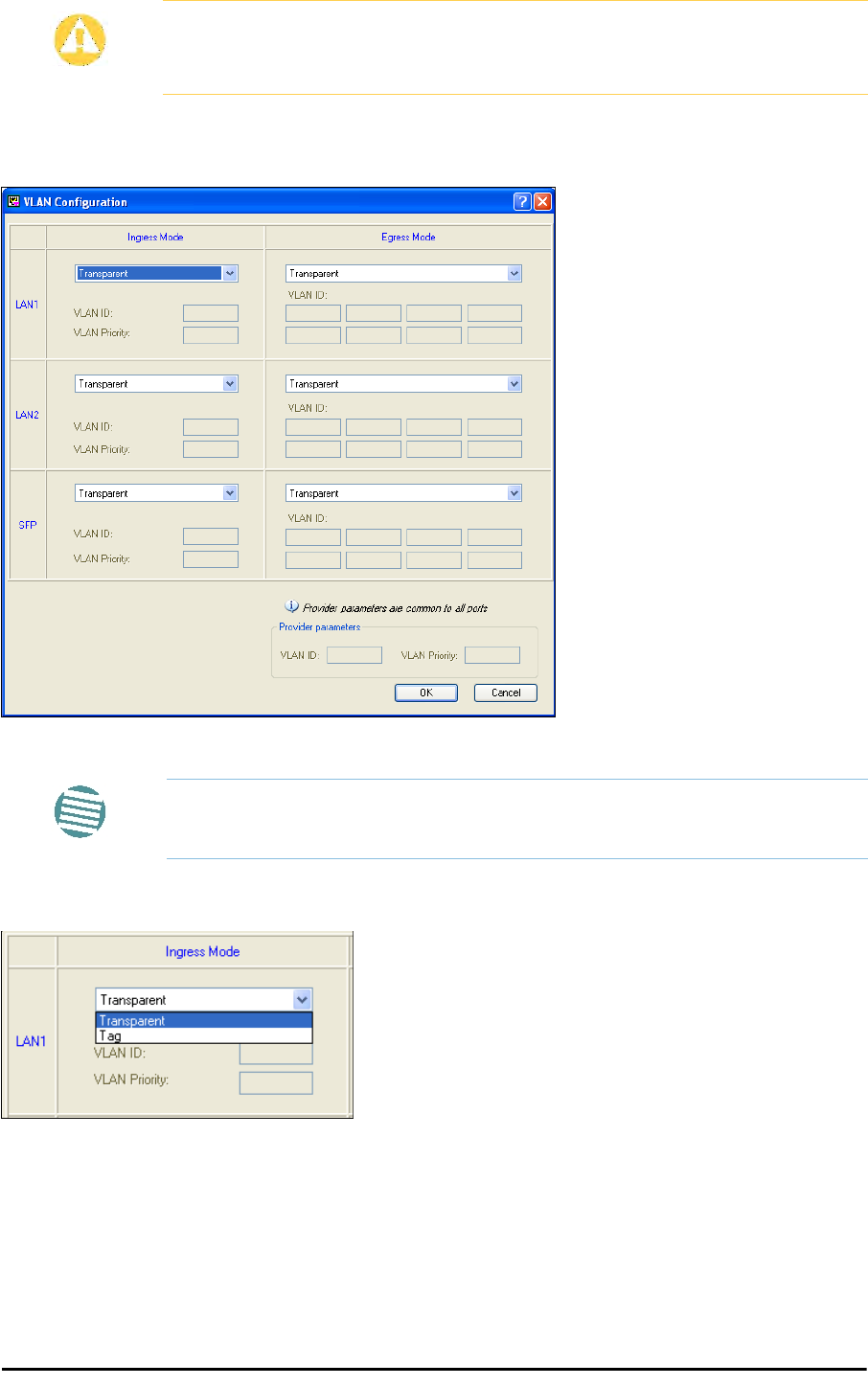
VLAN Tagging for Ethernet Service: Configuration Chapter 8
RADWIN 2000 User Manual Release 2.5.40 8-18
To set up VLAN tagging for Ethernet Service, click the VLAN Configuration... button in
Figure 8-15. The following window is displayed:
Figure 8-16: VLAN tag settings
The choices for Ingress Mode are -
and for Egress Mode are -
Caution
VLAN IDs are used by RADWIN products in three separate contexts:
Management VLAN, Traffic VLAN and Ethernet Ring. It is recommended that
you use different VLAN IDs for each context.
Note
If you are using a new style IDU-E, the SFP row will not appear.
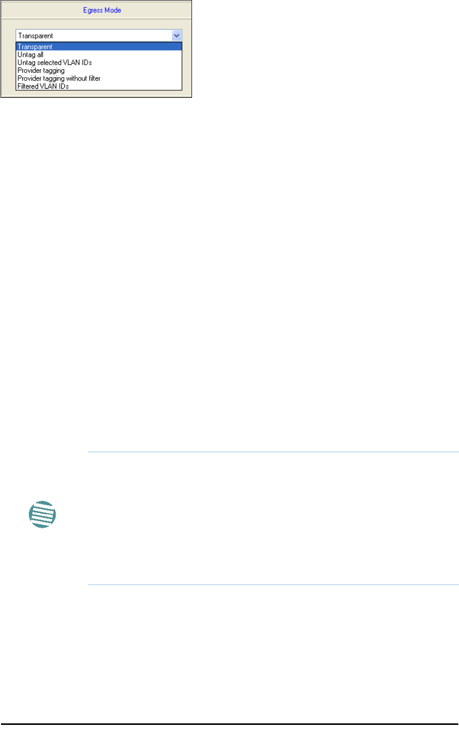
Setting the Maximum Information Rate (MIR) Chapter 8
RADWIN 2000 User Manual Release 2.5.40 8-19
The details of setting up VLAN tagging require advanced network management skills beyond
the scope of this manual. Further information for the Network Manager is provided in Chap-
ter 14.
Setting the Maximum Information Rate (MIR)
What is the MIR
The maximum Ethernet throughput of the link (MIR) can be limited. The default setting is
Best Effort
(see Figure 8-15 above), where the highest information rate available for the link
conditions and settings is used.
What is it for
The MIR setting limits the throughput for Ethernet service. It does not affect the capacity of
TDM services.
If the Link Budget Calculator or air conditions limit the capacity to X Mbps, and suppose that
you use Y (< X) Mbps for TDM services, then you are left with X - Y=Z Mbps for Ethernet.
Suppose for example, that Z = 20 Mbps.
As a Service Provider, you can decide to sell a package based on 10Mbps and charge $P1 for
it, or 15 Mbps for $P2 > $P1.
The MIR setting allows you do this.
The default value is “best effort” which will give Z above.
To limit the Ethernet information rate:
1. From the Configuration menu, choose the site to reconfigure.
2. Click Advanced | Ethernet
The Configuration dialog box opens.
Note
The minimum value is 256 Mbps.
The maximum value will be the minimum between Z above and -
• 10 Mbps for RADWIN 2000 PDH
• 50 Mbps for RADWIN 2000 L
• 100 Mbps for RADWIN 2000 C
The MIR setting is independent per direction.
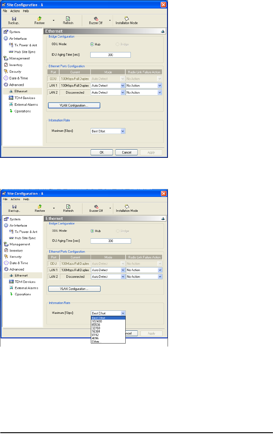
Setting the Maximum Information Rate (MIR) Chapter 8
RADWIN 2000 User Manual Release 2.5.40 8-20
Figure 8-17: Bridge Configuration - Site Configuration dialog box
3. In the Information Rate pane, use the drop-down menu to choose the MIR.
Figure 8-18: Ethernet MIR - Throughput selection
4. Choose Other to define the throughput with 1 Kbps resolution
5. Choose Best Effort for the highest information rate possible for the link conditions
and settings
6. Click Apply to save the changes.
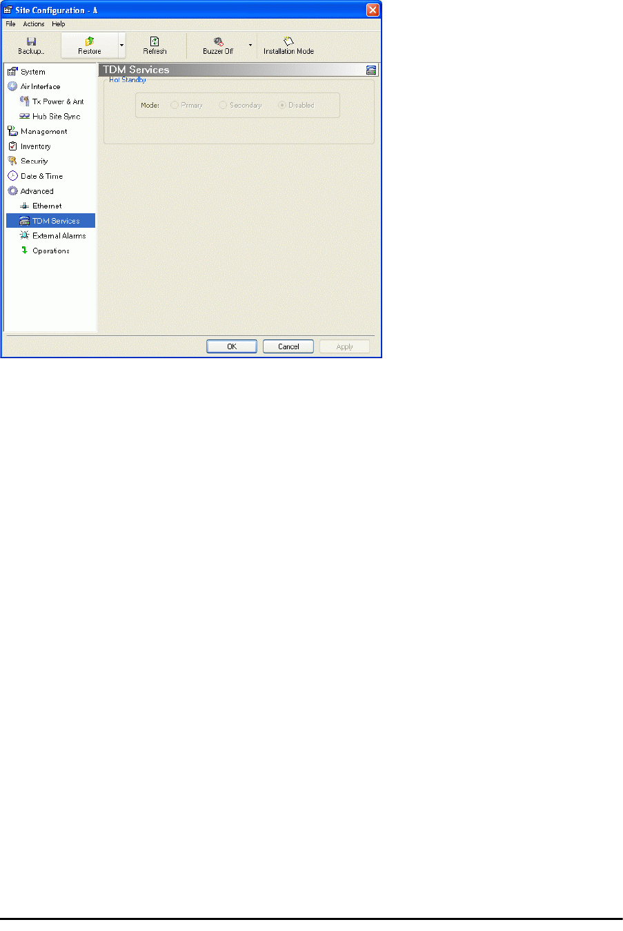
TDM MHS Status Chapter 8
RADWIN 2000 User Manual Release 2.5.40 8-21
TDM MHS Status
Here you can see the TDM MHS status. There is nothing to set.
Figure 8-19: TDM MHS status
Setting External Alarm Inputs
The IDU-C and the new style IDU-E have four external alarm inputs and four external alarm
outputs in the form of dry-contact relays. The Alarm interface is located on the front panel of
the IDU-C and is a 25-pin D-type female connector. See Appendix B, for wiring specifications
and pinout. You may enable or disable each of the alarms and configure the alarm description
text appearing in the alarm trap message. The ODU sends the alarm within less than a sec-
ond from actual alarm trigger.
To set the external alarm inputs:
1. Choose External Alarms from the Site Configuration window.
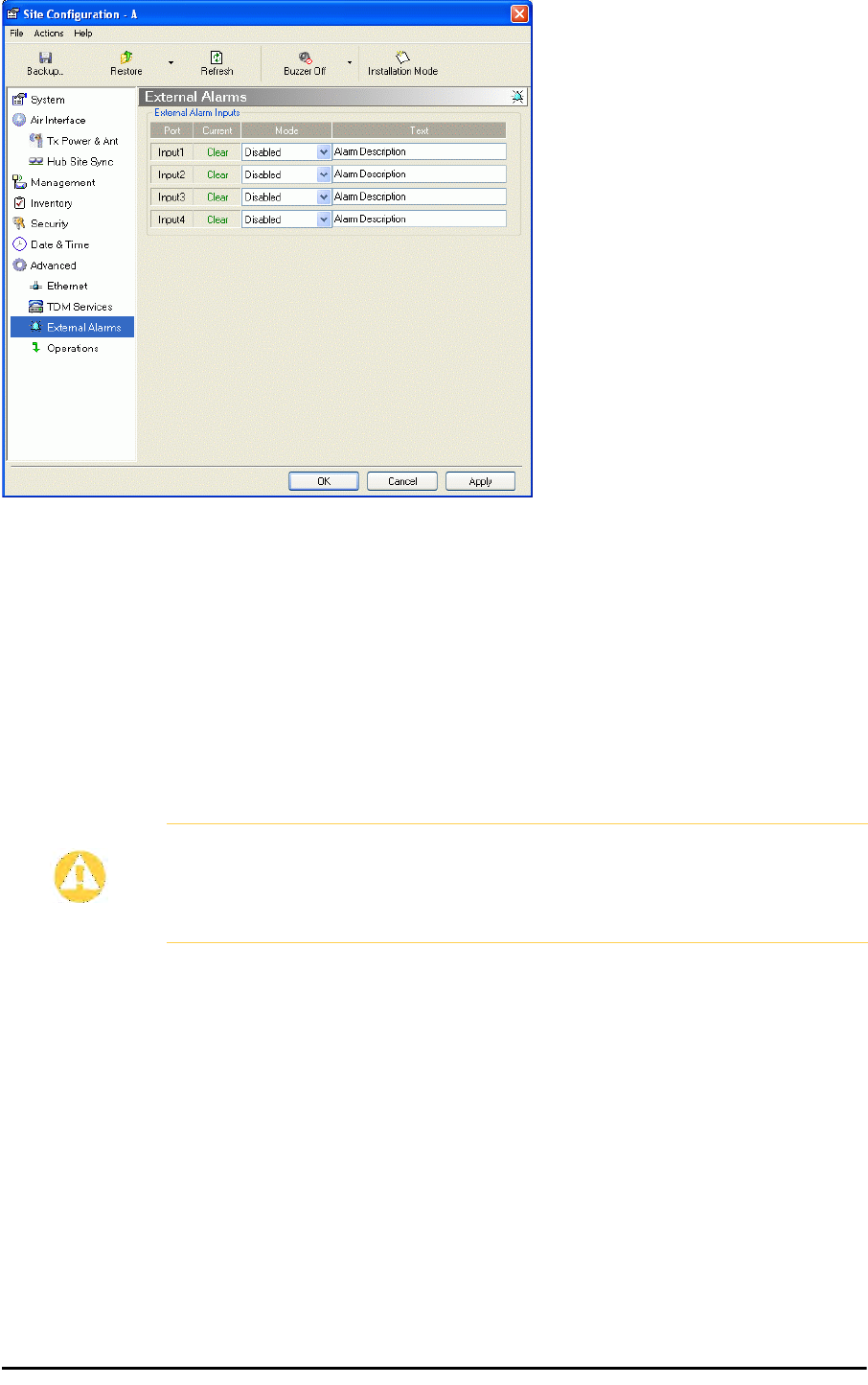
Resetting Chapter 8
RADWIN 2000 User Manual Release 2.5.40 8-22
Figure 8-20: External Alarms Configuration
2. Choose an alarm and set its mode to Enabled or Disabled
3. Enter a description of the alarms in the text field.
4. Click Apply to save.
5. Click OK to exit from the dialog.
Resetting
You may reset the link, preserving the current configuration, or reset to factory defaults.
To reset the link preserving current configuration:
1. From Maintenance on the main window, reset the remote unit.
2. From Maintenance on the main window, reset the local unit.
To reset to Factory Defaults
1. Choose either of the sites to be reset. The Configuration dialog box opens.
2. Choose Operations in the Configuration dialog box.
Caution
Resetting the link causes service disconnection.
To maintain the connection between the managing computer and
the link, first reset Site B.
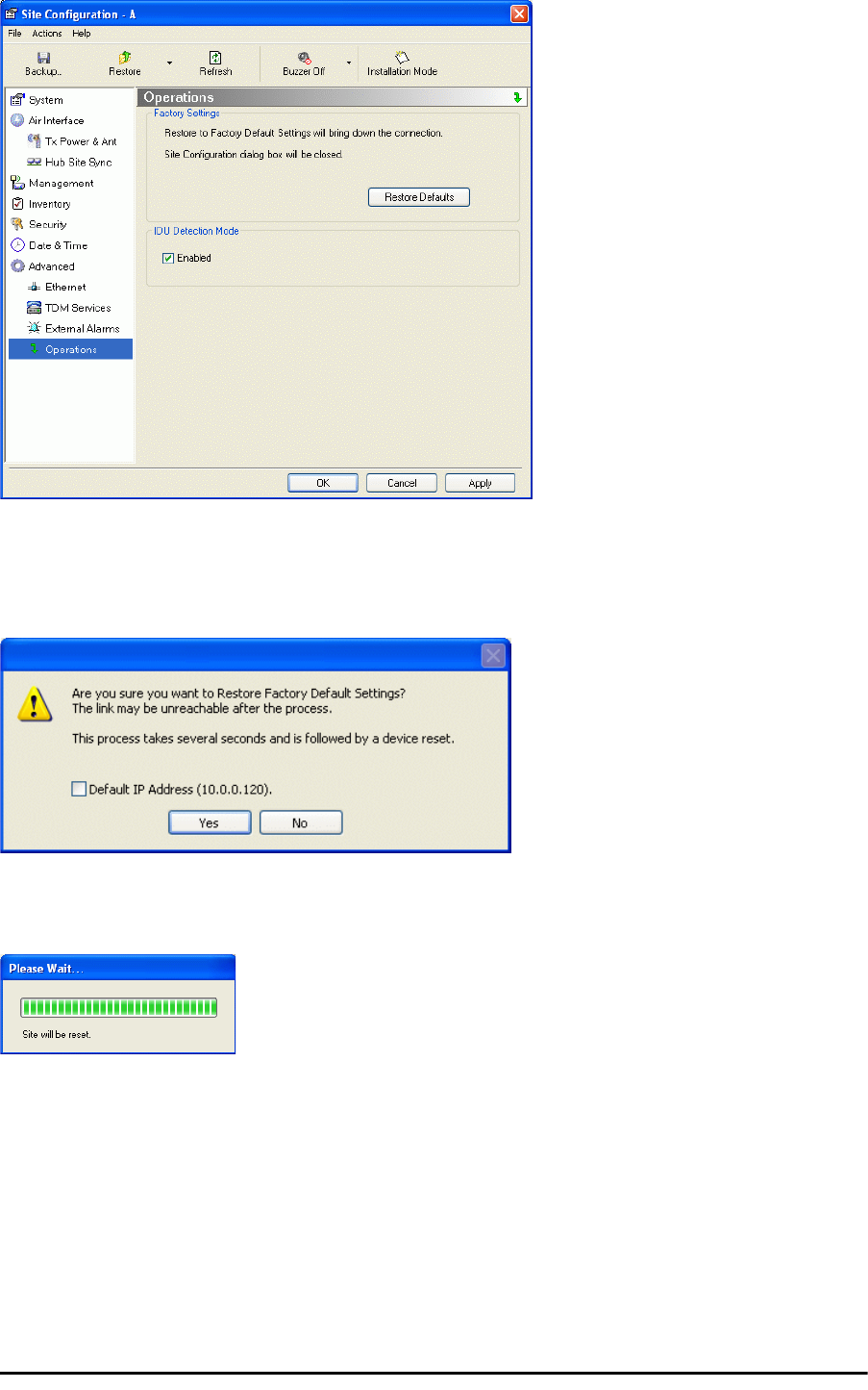
IDU Detection Chapter 8
RADWIN 2000 User Manual Release 2.5.40 8-23
Figure 8-21: Site Configuration - Reset to factory defaults
3. Click the Restore Defaults button.
A message box asking if you want to restore factory default settings appears.
4. Click the check box if you want to keep the current IP address settings.
5. Click Yes to continue.
After a few moments the site will be reset and you will need to log on to it to re-
install the link.
IDU Detection
An ODU always tries to detect the IDU to which it is connected. IDU Detection is effected by
an IDU responding to special ODU packets.
If a PoE device is in use, the detection packets spread to the containing network and may
cause flooding. In such a case, the IDU Detection feature, (Figure 8-21), should be dis-
abled.

Backup/Restore of ODU Software Files Chapter 8
RADWIN 2000 User Manual Release 2.5.40 8-24
To disable IDU Detection Mode, just toggle the check box in Figure 8-21.
Backup/Restore of ODU Software Files
Backup ODU Software to a File
RADWIN Manager allows you to backup the ODU software of both units of a link to the man-
aging computer as binary files. Each site is backed up in a separate file. Backup files are
matched to the MAC address of the site ODU. The default backup file name is constructed
from the ODU IP address and the date as in the following example:
Backup of Site A as used in our examples:
192.168.1.101_1.12.2009.backup
If you perform more than one backup on a given date you will need to change the file name
to something like this:
192.168.1.101_1.12.2009_00.backup
192.168.1.101_1.12.2009_01.backup
...
To backup the ODU software a file:
1. Choose a site to back up. The Site Configuration dialog box opens.
2. Click Backup.
3. In the Save As dialog box, indicate in which folder and under what name configura-
tion file is to be saved, and click Save.
Restoring ODU Software or Configuration
Backup files can be uploaded from the managing computer. You may choose a full software
restore or configuration-only restore.
To restore from a backup file:
1. Choose a site to restore (from a previous backup).
The Site Configuration dialog box opens.
2. Click Restore. You are offered the choice of a Full or Configuration Restore as
shown:
3. Click the required Restore type. You are then offered a standard Open File dialog
box.

Muting the alignment tone buzzer Chapter 8
RADWIN 2000 User Manual Release 2.5.40 8-25
4. From the Open File dialog box, navigate to your backup storage area and choose file
to upload. Click OK.
Muting the alignment tone buzzer
The ODU alignment tone becomes audible as soon as power is supplied, and continues until
the ODUs are aligned and the link established.
It is possible to mute the tone during regular operation of the link. It must be enabled when
performing the alignment procedure.
To mute the alignment tone buzzer:
1. Choose a site. The Configuration dialog box opens.
2. In the Configuration dialog box, click the Buzzer button.
Figure 8-22: Alignment tone buzzer states
3. Click Off. The tone is disabled.
To restore the alignment tone buzzer:
1. Choose a site. The Configuration dialog box opens.
2. Click On to have the buzzer beep continuously or Auto to have the buzzer beep only
in install mode.
Configuration with Telnet
A Telnet terminal can be used to configure and monitor the RADWIN 2000.
To start a Telnet session, use telnet <ODU_IP>.
For example, if you run Telnet as follows,
telnet 192.168.1.101
you will be asked for a user name and password.
The Telnet log on user name is the password that you used to enter the RADWIN Manager
(for example, the default:
admin
). The Telnet password is the corresponding Community
string (default:
netman
).

Configuration with Telnet Chapter 8
RADWIN 2000 User Manual Release 2.5.40 8-26
Figure 8-23: Telnet session log on
A Read-Only Community string allows display only whereas a Read-Write Community string
allows display and set commands.
Supported Telnet commands are shown in Table 8-2. Note that some of the commands are
model-specific. For example, TDM commands will not apply to Ethernet only and PoE based
links.
Table 8-2: Telnet Commands Summary
Command Explanation
display inventory Displays ODU product name, Name, Location, hardware and software
revisions, uptime, MAC address, IDU product name, IDU software and
hardware revisions
display management Displays IP, Subnet, Gateway, Traps table
display link Displays State, Link ID, Channel BW, RSS, TSL, Frequency/ACS, DFS,
Rate/ARA, Distance
display ethernet Displays Bridge Mode, Aging time, Port table (State, Status and action)
display tdm Displays Clock Mode, Master Clock Mode, Current Clock, Quality, TDM
table (Line status, Error Blocks)
display ntp Displays Time, Server and Offset
display PM <interface:AIR,LAN1,LAN2,TDM1,
TDM2,...,TDM16> <interval:current,day,month> Shows the performance monitor tables for each interface according to
user defined monitoring intervals
set ip <ipaddr> <subnetMask> <gateway> Set the ODU IP address, subnet mask and gateway. The user must reset
the ODU after the command completion
set trap <index:1-10> <ipaddr> <port:0-
65535> Set a specific trap from the traps table (e.g. set trap 3 192.168.1.101
162)
set readpw <oldpasswd> <passwd> Set the read access password (Read Community)
set writepw <oldpasswd> <passwd> Set the read-write access password (Read-Write Community)
set trappw <oldpasswd> <passwd> Set the trap Community string
set buzzer <mode:0=OFF,1 =ON> Toggle the buzzer mode (0 – off, 1 – on)
set tpc<power:Value between minimal Tx power,
and maximal Tx power> Set the ODU Tx Power. If a wrong value is entered, both min and max
values shall be displayed in the error reply
set bridge <mode:0=Bridging OFF,1= Bridging
ON > Set the ODU bridge mode (0 – off, 1 – on)
set name <new name> Set the name of the link
set location <new location> Set the name of the location

Configuration with Telnet Chapter 8
RADWIN 2000 User Manual Release 2.5.40 8-27
Figure 8-24, below, shows the available Telnet commands using the help command.
Figure 8-24: Telnet Management window
set contact <new contact> Set the name of the site manager
set <ssid> Set Link ID
set ethernet <port:MNG,LAN1,LAN2>
<mode:AUTO,10H,10F,100H,100F,DISABLE> Set the mode and speed of each Ethernet port
reboot Resets both the IDU and the ODU. The user is warned that the command
will reset the ODU. A new Telnet session to the ODU may be opened
after the reset is complete. (Watch the IDU LEDs.)
help Displays the available commands
admin@192.168.1.101-> Type "help" for help.
admin@192.168.1.101-> help
Display commands
display inventory
display management
display link
display ethernet
display tdm
display ntp
display PM <interface:AIR,MNG,LAN1,LAN2,TDM1,TDM2,TDM3,...,TDM15,TDM16>
<interval:current,day,month>
display bands
Set - immediate commands
set ip <ipaddr> <subnetMask> <gateway>
set trap <index:1-10> <ipaddr> <port:1-65535>
set readpw <writePasswd> <newPasswd>
set writepw <writePasswd> <newPasswd>
set trappw <writePasswd> <newPasswd>
set buzzer <mode:0=OFF,1=AUTO,2=ON>
set tpc <power:Value between minimal TX power, and maximal TX power>
set name <new name>
set location <new location>
set contact <new contact>
set ethernet <port:MNG,LAN1,LAN2> <mode:AUTO,10H,10F,100H,100F,DISABLE>
reboot
help
Set - reset required commands
set ssid <ssid>
set rate <index:1-15,adaptive>
set bridge <mode:0=Bridging OFF,1=Bridging ON>
Command "help" finished OK.
Table 8-2: Telnet Commands Summary (Continued)
Command Explanation

RADWIN 2000 User Manual Release 2.5.40 9-1
Chapter 9
Monitoring and
Diagnostics
The RADWIN Manager application enables you to monitor the link, as well as perform diag-
nostic operations such as loopback tests.
This chapter covers:
• Retrieving link information
• Link compatibility issues
• TDM port loopbacks
• Reinstalling and realigning a link
• Link Budget Calculator
• Performance monitoring
• Throughput checking
• Events, alarms and Traps
• Reverting alert messages
• Remote power fail indication
• Troubleshooting
•Replacing an ODU
• Restoring to factory setup
• Online help
• Obtaining support
Retrieving Link Information (Get Diagnostics)
The Get Diagnostics feature collects and writes all link and Manager information (from both
sites) into a text file. The file information can be used for diagnostics and should be sent to
RADWIN Customer Support to speed up assistance.
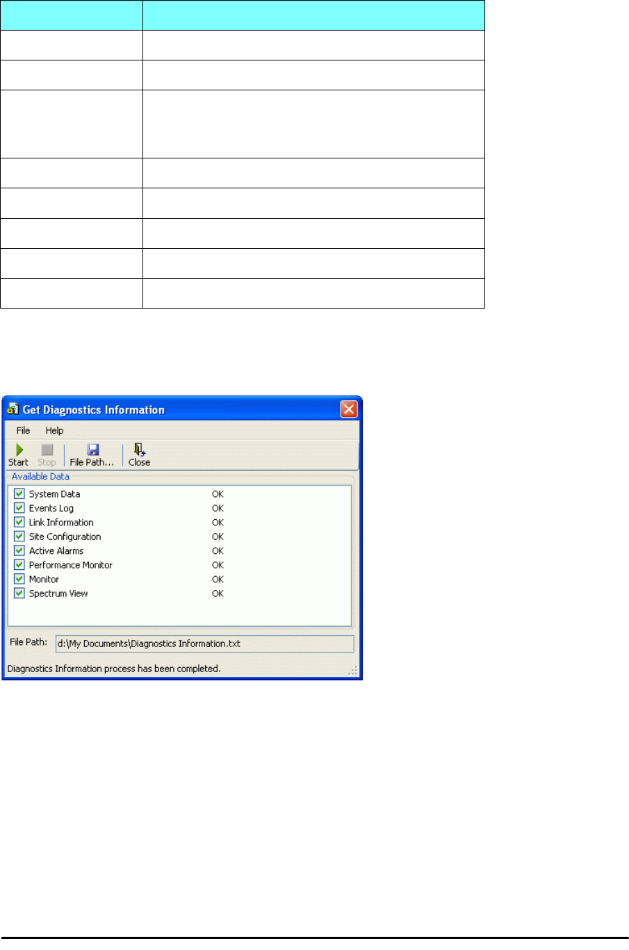
Retrieving Link Information (Get Diagnostics) Chapter 9
RADWIN 2000 User Manual Release 2.5.40 9-2
The following table lists link and system information that can be monitored.
To get diagnostics
1. From the Help menu, choose Get Diagnostics Information.
Figure 9-1: Get Diagnostics Dialog Box
2. Select or deselect the data options. If the file is to be sent to RADWIN Customer Sup-
port leave all options checked.
3. Click File Path to specify the folder in which you want to save the file and then click
Start to save the information.
The file is saved in the specified folder as Diagnostics Information.txt
Table 9-1: Get Diagnostics Data and Description
Data Description
System Data General information about the system
Link Information Information about the link properties
Events Log • List of system events including those from other sites if this
site is defined as the trap destination
• Last 256 events from both sites
Site Configuration Data about the site parameters
Active Alarms List of active alarms
Performance Monitor Network performance data over defined time periods
Monitor Detailed event data record
Spectrum View Data from last Spectrum View run

Link Compatibility Chapter 9
RADWIN 2000 User Manual Release 2.5.40 9-3
Link Compatibility
Link Compatibility indicates the version compatibility using software traps. As new hardware
or software is added to existing networks compatibility issues may arise. An incompatibility
issue is indicated to the user by a change of color of the Link Status box on the Main Menu
window. Trap messages (can be viewed in the Events Log) indicate the problems or limita-
tions and suggest upgrades when appropriate.
The following Link Status messages are given:
fullCompatibility - different software versions were detected that are fully compatible. The
message indicates that an upgrade is available.
restrictedCompatibility - different software versions were detected that operate correctly.
However, new features are not supported.
softwareUpgradeRequired - different software versions were detected allowing limited opera-
tion. The message is, that a software upgrade is required.
versionsIncompatibility - different software versions were detected that are incompatible. You
need to perform local upgrades.
TDM Loopbacks
Internal and external loopbacks on both sites of a link are used to test the TDM
connections
To activate a loopback:
1. From the Maintenance menu, choose Loopbacks... or right-click the TDM
display in the main window.
The Loopbacks dialog box appears:
Table 9-2: Link Compatibility Trap Messages
Link State Link State
text Link Status
Color Site Description
fullCompatibility Active Green Software Upgrade
Available
restrictedCompatibility
Active -
Software
Version
mismatch
Magenta
(Same as
authenticatio
n error)
Software Upgrade
Recommended
softwareUpgradeRequired
Active –
Software
Upgrade
Required
Brown
(Major) Software Upgrade
Required
versionsIncompatibility
Not Active -
Software
Upgrade
Required
Red Local Software
Upgrade Required
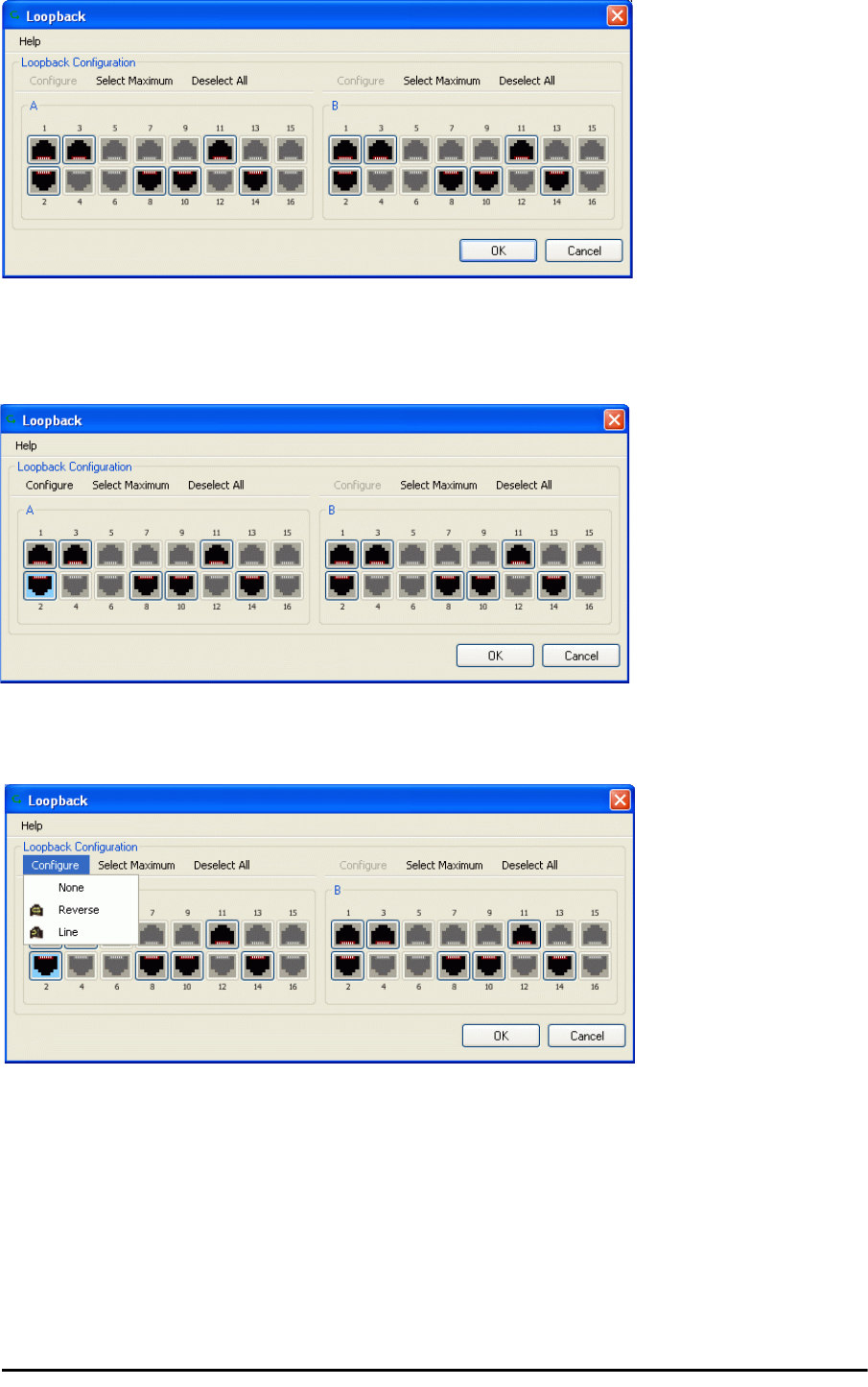
TDM Loopbacks Chapter 9
RADWIN 2000 User Manual Release 2.5.40 9-4
Figure 9-2: Loopback configuration box
2. From the active ports, click those required for loopback activation. The selected port
icons change color to light blue as in the following example:
Figure 9-3: Loopback configuration box with one Site A port selected
3. Click configure to choose a loopback mode:
Figure 9-4: Loopback options
4. Click the required loopback mode.
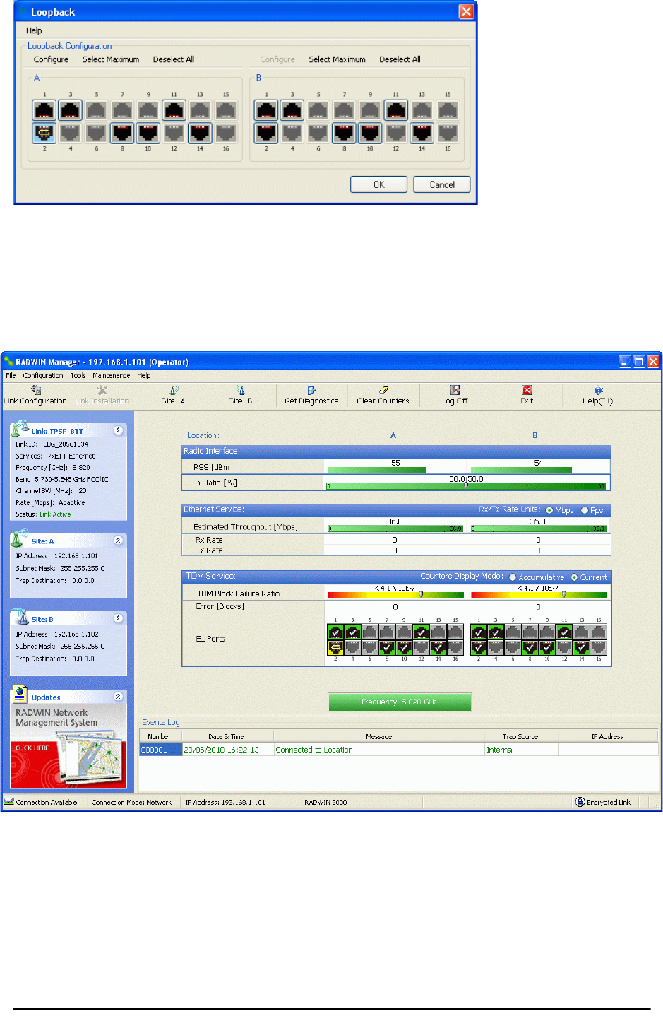
TDM Loopbacks Chapter 9
RADWIN 2000 User Manual Release 2.5.40 9-5
Figure 9-5: Loopback defined
5. Click OK to activate the selected loopback(s).
This activates selected loopback(s). The corresponding service port icon
changes color and appearance to indicate an active loopback.
Figure 9-6: Site A port 2 set to loopback
To deactivate a loopback:
• Return to the situation of Figure 9-4 and click None.
When a loopback is deactivated, the corresponding icon in Figure 9-6
reverts to its previous state (like the right side of the figure).
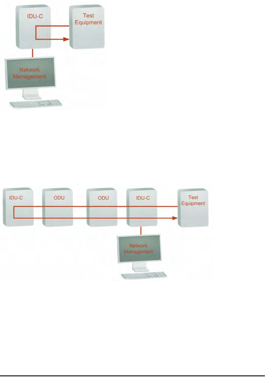
Local Line Loopback Chapter 9
RADWIN 2000 User Manual Release 2.5.40 9-6
Local Line Loopback
A Local line loopback can be set to test the local E1/T1 port and its connection to local side
user equipment. In this mode, data coming from the local user equipment is looped back to
it. This loopback is initiated from a managing computer connected to the local unit.
Figure 9-7: Local Line Loopback
Remote Reverse Loopback
A remote reverse loopback can be set to test connection between the local and remote units
and between the local E1/T1 port and its connection to the local user equipment. In this
mode, data coming from the local user equipment is looped back at the remote side. This
loopback is initiated from a managing computer connected to the local unit.
Figure 9-8: Remote Reverse Loopback
Remote Line Loopback
The remote unit can be set to a line loopback to test the remote E1/T1 port and its connec-
tion to the remote side user equipment. In this mode, data coming from the remote user
equipment is looped back to it locally. This loopback is initiated by the managing computer
connected to the local unit.
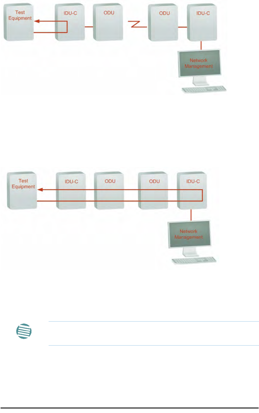
Local Internal Loopback Chapter 9
RADWIN 2000 User Manual Release 2.5.40 9-7
Figure 9-9: Remote Line Loopback
Local Internal Loopback
The local unit can be set to close a remote loopback to test connection between the local and
remote units and between the remote E1/T1 port and its connection to the remote user
equipment. In this mode, data coming from the remote user equipment is looped back to it
locally. This loopback is initiated by the managing computer connected to the local unit.
Figure 9-10: Local Reverse Loopback
Reinstalling and Realigning a Link
It may be necessary to reinstall the link if the ODUs need to be realigned.
To reinstall the link:
1. Choose a site.
The Configuration dialog box opens.
2. In the Configuration dialog box, click the Install Mode button.
Note
Activating Install Mode causes both sites to go into install mode, causing
disruption in service for approximately fifteen seconds.
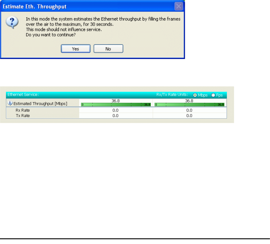
The Link Budget Calculator Chapter 9
RADWIN 2000 User Manual Release 2.5.40 9-8
A message box asking if you want to enter install mode appears.
3. Click Yes to continue.
The system enters Install mode and the alignment tone becomes audible.
4. Realign the ODUs and start the Installation wizard (see Chapter 5).
The Link Budget Calculator
The Link Budget Calculator is part of the RADWIN Manager software and is found in the Help
menu. This useful utility enables you to calculate the expected performance of the wireless
link and the possible configurations for a specific link range including antenna size, cable loss
and climate conditions. For full details, see Chapter 21.
Throughput Checking
In this mode, RADWIN 2000 estimates Ethernet throughput by filling frames over the air to
maximum for 30 seconds. This mode should not influence service.
To use Throughput Checking:
1. At the main menu, click Maintenance | Estimated Eth. Throughput. A confirma-
tion message appears:
2. Click Yes to continue. The Ethernet services area changes appearance and the esti-
mated throughput is displayed:
At the end of 30 seconds, the display reverts to normal.
Performance Monitoring
RADWIN 2000 Performance Monitoring constantly monitors traffic over the radio link and col-
lects statistics data for the air interface, TDM and Ethernet ports. It does so continuously,
even when the RADWIN Manager is not connected.
Two types of logs are recorded:
•Monitor Log that records statistics on traffic rate and radio signal strength.
•Events Log that records when the rates fall above or below a predefined threshold.
See page 9-13 below.
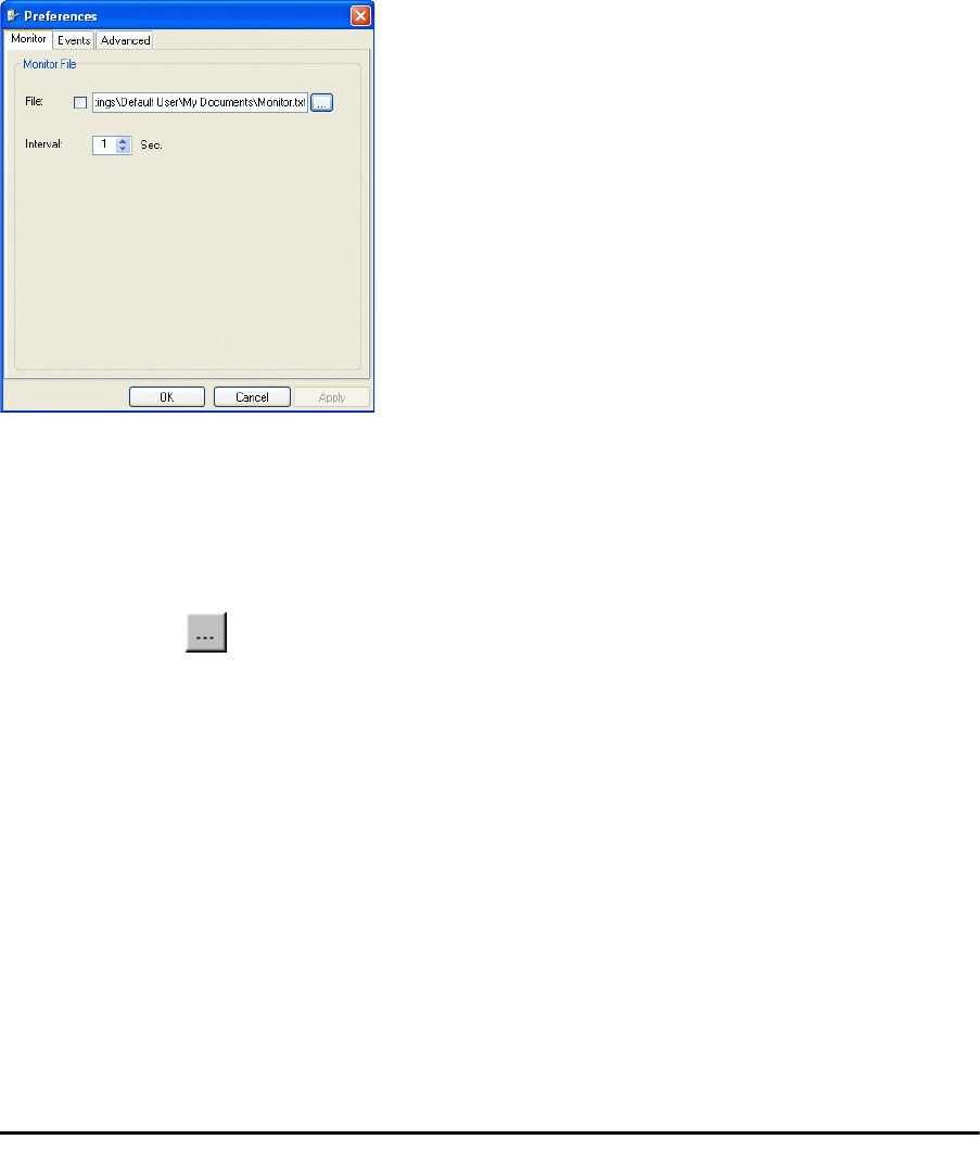
The Monitor Log Chapter 9
RADWIN 2000 User Manual Release 2.5.40 9-9
Both the statistics Monitor log and events log can be saved as text files.
The Monitor Log
The Monitor Log records performance statistics for predefined intervals. You can save the
monitor log to a text file, as well as display the information in an on-screen report.
Saving the Monitor Log
You can save the recorded Monitor Log statistics to a text file.
To save the monitor log:
1. From the Tools menu, choose Preferences.
The Preferences dialog box appears:
Figure 9-11: Preferences dialog box
2. Click the Monitor Tab.
3. Select the file to save.
4. Click the check box to open the file for saving.
5. Click the button and in the Select File dialog box indicate in which folder and
under what name the monitor log file is to be saved.
6. Set the time interval for adding data to the file.
7. Click OK to save the file.
Viewing Performance Reports
The Performance Monitor Report displays performance views of each of the interfaces.
To obtain performance monitoring reports:
1. From the main menu, choose Tools | Performance Monitoring Report ...
You are presented with the following window:
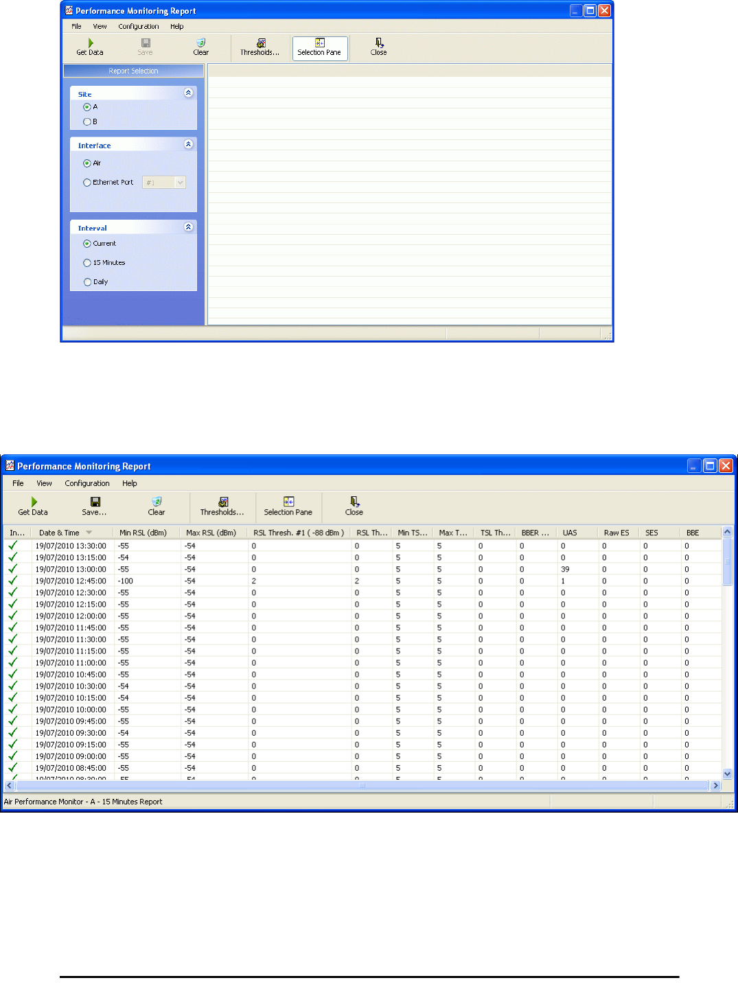
The Monitor Log Chapter 9
RADWIN 2000 User Manual Release 2.5.40 9-10
Figure 9-12: Basic Performance Monitoring Report
2. Choose a report type from the left panel and click the Get Data toolbar button. For
example, if you choose Site A, Air and Current, you will be offered a report looking
like this:
Figure 9-13: A typical Performance Monitoring Report based on 15 minute intervals
Notice the Min RSL value of -100 on the fourth line. It Indicates that during the inter-
val 12:30 to 12:45, there was a link sync loss. The next figure shows the effect of a
reset between 14:15 and 14:30.
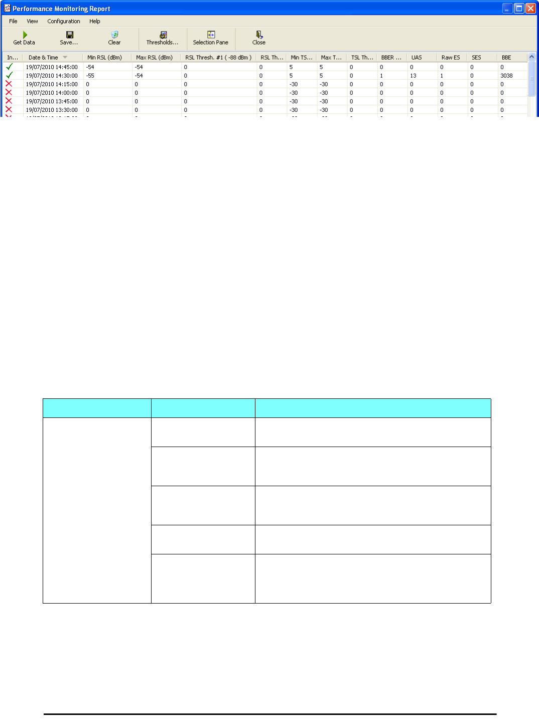
The Monitor Log Chapter 9
RADWIN 2000 User Manual Release 2.5.40 9-11
Figure 9-14: Performance Monitoring Report showing the effect of a Reset
The prior data is invalidated as shown by the red crosses in the left hand column.
Further, Min and Max RSL for the invalidated period is set to zero.
3. Click the Selection Pane icon to toggle the side panel on or off.
The other reports look similar. Here is a detailed description of the reports and their fields:
Several performance data occurrences are collected for each of the interfaces (ES, SES, and
UAS), as well as specific data per Interface type (e.g., Tx and Rx bytes for Ethernet). For the
Air Interface, user defined thresholds data are collected. Refer to Table 9-3 and Table 9-4
below.
Data is collected and selectively displayed based on three time intervals as selected by the
Interval radio buttons:
• Current (t=0)
• 15 minutes Intervals
• Daily
Table 9-3: Explanation of performance data
Data type Reported Value Explanation
Generic PM Data
UAS – Unavailable
Seconds Seconds in which the interface was out of service.
Raw ES – Raw Errored
Seconds
The number of seconds in which there was at least one error
block. Note that the notion of an error block is different per
interface.
SES – Severe Errored
Seconds
The number of seconds in which the service quality was low
(the quality is different per type of interface and determined by
the BBER threshold per interface).
BBE – Background Block
Error The number of errored blocks in an interval.
Integrity
A flag indicating that the data was valid. Note that the
Performance Monitoring data is not valid if not all the values
were stored (e.g., due to clock changes within the interval or
power up reset).

The Monitor Log Chapter 9
RADWIN 2000 User Manual Release 2.5.40 9-12
Performance Monitoring Report Toolbar
You can use the toolbar to perform the actions described in the following table:
Setting Air Interface Thresholds
Use the Thresholds button on the Monitoring Performance Report toolbar to set the Air
Interface Thresholds:
Additional Air Interface
PM Data
Max RSL The maximum of the receive signal level (measured in dBm).
Min RSL The minimum of the receive signal level (measured in dBm).
Max TSL The maximum of the transmit signal level (measured in dBm).
Min TSL The minimum of the transmit signal level (measured in dBm).
RSL Threshold 1 The number of seconds in which the Receive Signal Level (RSL)
was below the specified threshold.
RSL Threshold 2 The number of seconds in which the RSL was below the
specified threshold.
TSL Threshold The number of seconds in which the Transmit Signal Level
(TSL) was above the specified threshold.
BBER Threshold The number of seconds in which the Background Block Error
Ratio (BBER) exceeded the specified threshold.
Additional Ethernet
Interface PM Data
Received Bytes The number of Megabytes received at the specified port within
the interval
Transmitted Bytes The number of Megabytes transmitted at the specified port
within the interval.
Throughput threshold Seconds count when throughput fell below the threshold
Traffic threshold Seconds count when actual traffic exceeded the threshold
TDM interface Active seconds The number of seconds that the configured TDM services are
active
Table 9-4: Action of the toolbar buttons
Command Button Action
Get Data Gather current performance monitoring data.
Save Save current performance monitoring data to a file
Clear Clear current performance monitoring data
Thresholds Set Thresholds
Selection Pane Toggle on/off left panel
Close Closes the Performance Monitoring window
Table 9-3: Explanation of performance data
Data type Reported Value Explanation

Events, Alarms and Traps Chapter 9
RADWIN 2000 User Manual Release 2.5.40 9-13
Figure 9-15: Threshold configuration dialog box
RSL Thresholds
Two RSL Thresholds can be defined. They are used as an indicator of problems in the radio
channel. You can check the RSS from the Link Budget Calculator results during installation.
Values of -5dB and -8dB from the current RSS are typical.
TSL Threshold
A counter is maintained, of the number of second intervals during which Tx power exceeds
this threshold.
BBER Threshold
The Background Block Error Ratio is measured as a percentage. The threshold can be set
from 0.1% up to 50%.
For links with Ethernet only service, 8% threshold is recommended. If there are no problems
during the interval, then for that threshold, the recommended BBER value should be 0. Since
the system provides a lossless Ethernet service, there is throughput degradation in case of
interference. The degradation is proportional to the BBER.
Ethernet Thresholds - Capacity
This is used as a basis for checking adherence to a Service Level Agreement. It is the number
of seconds count that the link capacity falls bellow the threshold.
Ethernet Thresholds - Traffic
The number of seconds count that received traffic exceeded this threshold. It can be used to
measure traffic peaks.
Events, Alarms and Traps
The Events Log
The Events Log records system failures, loss of synchronization, loss of signal, compatibility
problems and other fault conditions and events.
Note
The foregoing event types include events from all links for which this
managing computer has been defined as the traps address. Only events
from RADWIN equipment will be shown.
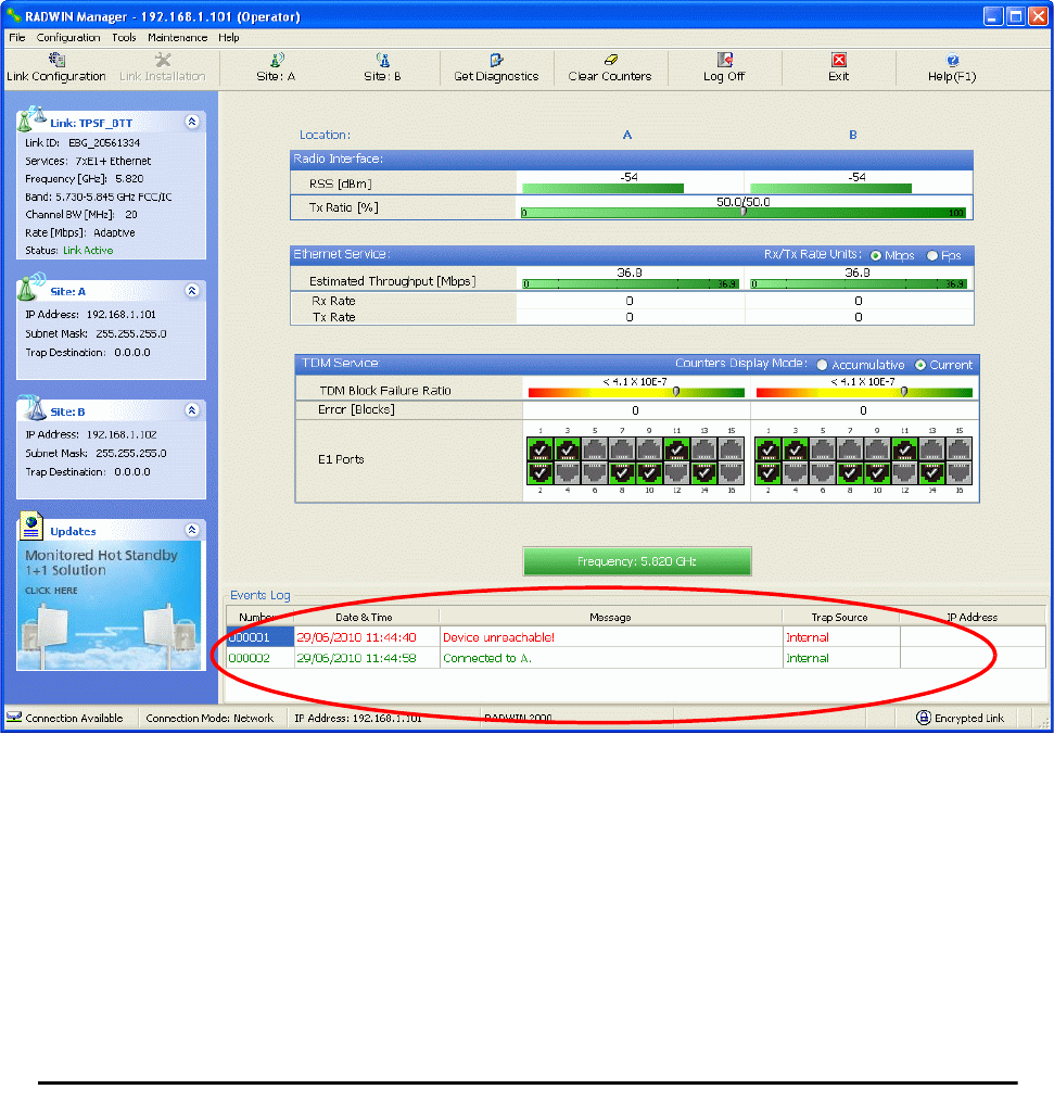
The Events Log Chapter 9
RADWIN 2000 User Manual Release 2.5.40 9-14
Alarms (traps) are displayed in the Events Log in the lower panel of the main window. The
Events Log may be saved as a text file.
The Events Log includes the following fields:
»Sequential number (ID)
»Date and time stamp
»Message
»Trap source
»IP address of the ODU that initiated alarm.
For complete information about traps and alarms see Appendix E.
The events are displayed in the Events Log in the lower right-hand panel of the RADWIN
Manager main window:
Figure 9-16: Events Log Display
To save the Events Log:
1. From the Tools menu, choose Preferences.
The Preferences dialog box appears
2. Click the Events Tab.
3. Select the file to save.
4. Click the check box to open the file for saving.

RADWIN Manager Traps Chapter 9
RADWIN 2000 User Manual Release 2.5.40 9-15
Click the button and in the Select File dialog box indicate in which folder and under what
name the Events Log file is to be saved, and click OK.
RADWIN Manager Traps
The RADWIN Manager application issues traps to indicate various events, displayed in the
Events Log.
Note
To store the Events Log, first define the IP address, subnet mask, default
gateway and trap destination address of the managing computer (see
page 8-7 for details).
Table 9-5: RADWIN Manager Trap Messages
Trap Message Severity Remarks
Cannot bind to trap service port. Port 162 already in use by
ProcessName (pid: ProcessId) Warning RADWIN Manager will not catch any traps from the
ODU, some other application has grabbed this
port. For further detail see this web site.
Device unreachable! Error Check connectivity to ODU
Connected to <site_name> Information
<site_name> Site will be reset. Information
Restore Factory Default Settings in process on Site <site_name> Information
Factory Settings: The process was not finished due to connection
issues. Warning Factory setting failed due to connectivity problem
to ODU
Reset: The process was not finished due to connection issues. Warning Factory setting failed due to connectivity problem
to target - ODU will not be reset
Cannot Write to Monitor file. There is not enough space on the disk. Warning Free some space on disk on the managing
computer and retry
Windows Error: <error_ID>. Cannot Write to Monitor file. Warning Operating System error on the managing computer
TDM Counters were cleared for both sides Information
Identical IP addresses at <local_site_name> and
<remote_site_name> Warning Set up a different IP to each site
The Product is not identified at the <local_site_name> site. Warning RADWIN Manager is incompatible with the ODU
software version
The Product is not identified at the <remote_site_name> site. Warning
The Product is not identified at both sites. Warning
Product Not Identified! Warning
The Manager identified a newer ODU release at the
<remote_site_name> site. Warning ODU release is newer than RADWIN Manager
release.
Wizards are not available. RADWIN Manager will
be used just for monitoring. Upgrade the RADWIN
Manager. (You will get this message as a pop up)
The Manager identified a newer ODU release at both sites. Warning
The Manager identified a newer ODU release at the
<local_site_name> site. Warning
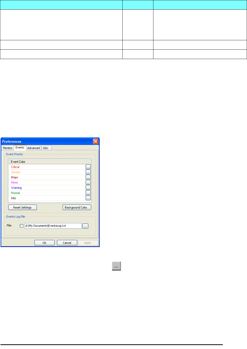
Setting the Events Preferences Chapter 9
RADWIN 2000 User Manual Release 2.5.40 9-16
Setting the Events Preferences
You can define a color for the messages to be displayed in the Event Log window, according
to the severity of the event. The severity is predefined.
To set the Message color:
1. From the Tools menu, choose Preferences.
The Preferences dialog box appears.
2. Click the Events Tab:
Figure 9-17: Preferences dialog box - Event tab
3. Select the event type and click on the button.
A color chart opens.
4. Select the required color.
5. Repeat for each of the event types.
To set the message background color:
• Click Background Color to change the text background.
Newer Version identified at the <local_site_name> site. Warning ODU release is newer than RADWIN Manager
release.
Wizards are not available. RADWIN Manager will
be used just for monitoring. Upgrade the RADWIN
Manager.
Newer Version identified at the <remote_site_name> site. Warning
Newer Version Identified! Warning
Table 9-5: RADWIN Manager Trap Messages (Continued)
Trap Message Severity Remarks
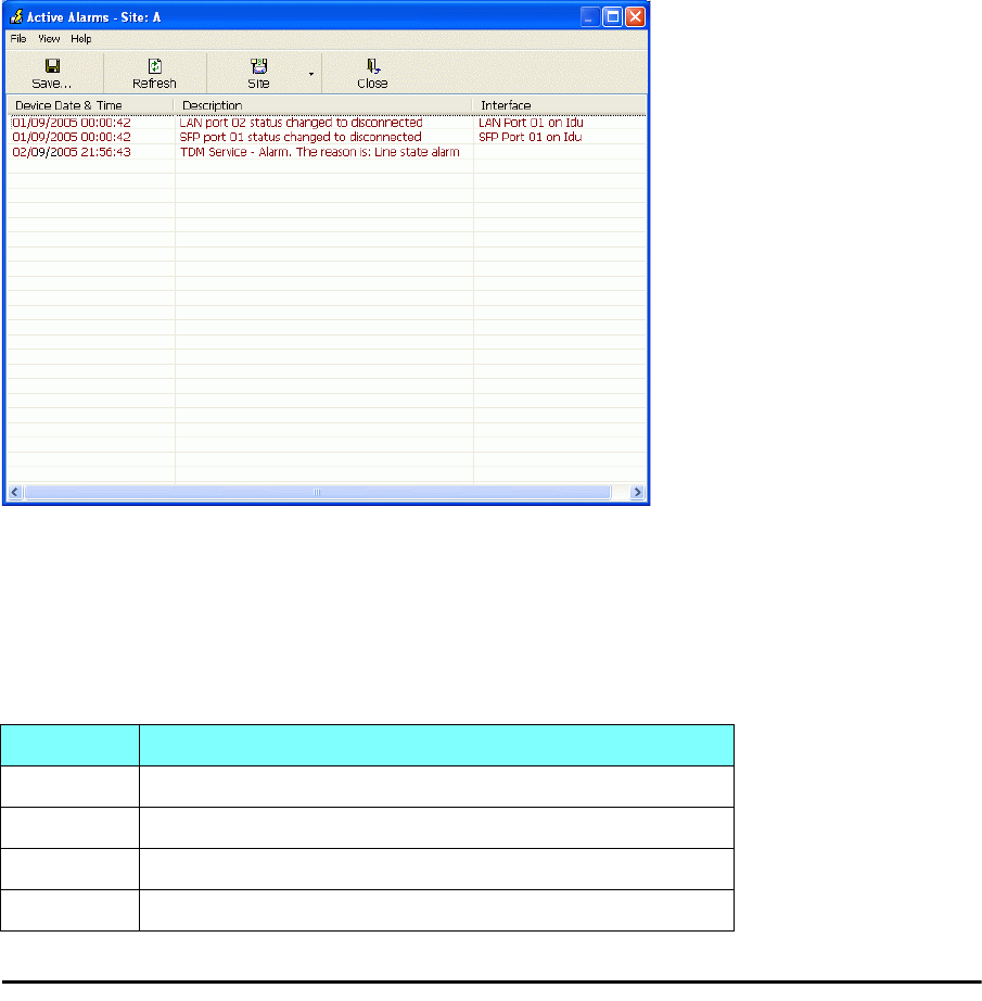
Saving the Events Log Chapter 9
RADWIN 2000 User Manual Release 2.5.40 9-17
To reset the message colors:
• Click Reset Settings to return to the default color settings.
Saving the Events Log
You can save recorded events in an Events Log text file. New alarms are automatically added
to the text file, as they enter the Events Log.
Active Alarms
Upon setting a trap destination, applicable events are reported as active alarms to the user.
The active alarms are saved and can be viewed in the Active Alarms window.
To view summary of saved alarms:
1. From the Tools menu, choose Active Alarm Summary.
2. Choose either of the sites offered.
The Active Alarms Summary window opens:
Figure 9-18: Active Alarms Summary
The active alarms display does not update itself until the Refresh button is used.
The following table provides an explanation of the command buttons.
Table 9-6: Active Alarms command buttons
Command Action
Save Saves the alarms in CSV or text format for further analysis
Refresh Shows the active alarms at the moment of refresh
Site Selects site for the active alarms
Close Closes the active alarm window
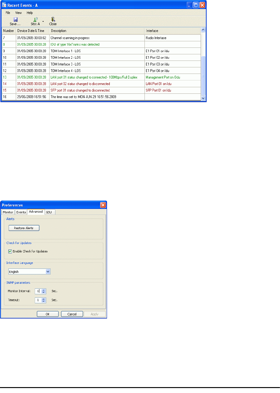
Viewing Recent Events Chapter 9
RADWIN 2000 User Manual Release 2.5.40 9-18
Viewing Recent Events
Each ODU stores the last 256 events:
To view the last 256 events:
1. Click Tools | Recent Events ... A window like the following is displayed:
Figure 9-19: Recent Events - Up to last 256 events at Site A
2. Use the Site button to choose Site B
3. Use the Save button to store the events in a tab-delimited list.
Reverting Alert Messages
Many alert messages in the RADWIN Manager have an option of the form “Do not show this
message again”. These alert messages can be reverted to their default state (shown) by
choosing the Advanced tab from the Preferences dialog:
Figure 9-20: Advanced Preferences
Just click the Restore Defaults button, followed by OK.

Other Advanced Preferences Chapter 9
RADWIN 2000 User Manual Release 2.5.40 9-19
Other Advanced Preferences
Enable and Disable Checking for Software Updates
If you are not on a network with Internet access, disable this.
Setting the RADWIN Manager Language
In the dialog of Figure 9-20, you can set the RADWIN Manager interface language, where
other localizations are available.
Setting SNMP Parameters
Use these choices to set the SNMP monitoring interval and time-out. These are only signifi-
cant if you are using an SNMP based network management system such as RADWIN NMS.
Remote Power Fail Indication
Remote power fail indication indicates to one side that the other side has suffered a power
failure. The failed site sends a final trap indication about the power loss just before powering
off.
A “Dying-Gasp” circuit identifies the power failure at a minimum interval of 20 milliseconds
before the ODU or IDU powers off. During that interval a message notifying the power failure
is sent to opposite site. External alarm output number 4 indicates power failure at the oppo-
site site.
Troubleshooting
Use the following table to troubleshoot LED fault indications:
Table 9-7: LED fault indicators
LED Status Remedy
PWR Off Check that power is connected to the IDU
IDU Red Check that the IDU/ODU cable is properly wired and connected.
ODU Red Check that the IDU/ODU cable is properly wired and connected.
AIR I/F
Orange Complete the installation procedure from the RADWIN Manager
Red Check the antenna alignment. Check that the radio configuration of both site A and
site B units are the same (Channel and Link ID).
SVC Orange
Red
Off
Alarm detected at the Site B interface or Local or Remote loopback
Alarm detected at the Site A interface
Ethernet only IDU or E1/T1 not configured

Replacing an ODU Chapter 9
RADWIN 2000 User Manual Release 2.5.40 9-20
Use the following table to troubleshoot faults in the system:.
Replacing an ODU
Prior to any action ensure that both ODUs have the same software version. You can see this
on the inventory panels for each site.
For Site A, click Site A | Inventory and note the ODU software version. Repeat this for Site
B using Site B | Inventory.
If either ODU has an old software version, perform a software upgrade. It is important to con-
figure the new ODU identically to the old ODU to avoid configuration mismatches, which will
disrupt the link.
An ODU may be reconfigured in several ways.
• Use the backup configuration
If a backup of the configuration is available, restore that configuration using Site A|
Restore. Recall that backup files are linked to a MAC address. This won’t work for
an identical replacement ODU.
• Manual configuration
The new ODU can be configured manually according to the link configuration.
Remember to use the same settings for Link ID, channels, link password, IP
addresses, and names.
HSS
Red
Orange HSS not operational due to improper signal detection. This ODU is not transmitting
HSS is operational. One of the following conditions apply:
• This ODU is a master that is generating signals and detecting signals
• This ODU is a master that is generating signals but detected improper sig-
nals
• This ODU is a client “Continue Tx” but is not detecting signals
• This ODU is a client “Disable Tx” and is detecting signals from multiple
sources
All orange cases transmit.
STBY Red
Orange MHS mode Primary, Link state not active
MHS mode Secondary, Link state active
Table 9-8: System Troubleshooting
Symptom Remedy
No power Ensure that power is connected to the IDU
Ensure that the ODU cable is properly wired and connected
No signal
Complete the installation procedure from the RADWIN Manager
Check the antenna alignment. Check that the radio configuration of both site A and site B
units is the same (channel settings and Link ID)
Weak signal
received
Check the antenna alignment, reconfigure the link
Check the alignment tone sounds the Best Signal sequence
Table 9-7: LED fault indicators (Continued)
LED Status Remedy

Restoring Factory Setup Chapter 9
RADWIN 2000 User Manual Release 2.5.40 9-21
Restoring Factory Setup
To restore factory setup:
• Use Site Configuration A or B, and then Operations | Restore Defaults. Always
restore the over-the-air site (B) first.
Online Help
Online help can be accessed from the Help menu on the main window of the RADWIN Man-
ager.
Customer Support
Customer support for this product can be obtained from the local VAR, Integrator or distribu-
tor from whom it was purchased.
For further information, please contact the RADWIN distributor nearest to you or one of RAD-
WIN's offices worldwide (see RADWIN Worldwide Offices at the beginning of this man-
ual).

RADWIN 2000
Broadband Wireless Transmission System
USER MANUAL
RELEASE 2.5.40
Part 2: Site Synchronization
UM 2000-2540/02.11

RADWIN 2000 User Manual Release 2.5.40 10-1
Chapter 10
Hub Site Synchronization
What is Hub Site Synchronization?
When several units are collocated at a common hub site, interference may occur from one
unit to another. RADWIN ODU units support the collocation of more than two units at a cen-
tral site. Like any other RF deployment, the wireless operation is highly dependent on factors
such as available frequencies, the physical spacing between radios, other interfering radios,
and whether WinLink 1000 or RADWIN 2000 units are installed.
The RADWIN Hub Site Synchronization (HSS) method uses a cable connected from the mas-
ter ODU to all collocated ODUs; this cable carries pulses sent to each ODU, which synchronize
their transmission with each other. The pulse synchronization ensures that transmission
occurs at the same time for all collocated units. This also results in all of the hub site units
receiving data at the same time, eliminating the possibility of interference that could result if
some units transmit while other units at the same location receive.
Figure 10-1 illustrates interference caused by non-synchronized collocated units.
Note
HSS does not eliminate the need for careful RF planning to ensure the
design will work as planned. See Chapter 2 of the User Manual (both
WinLink 1000 and RADWIN 2000) for information on installation site survey.
For WinLink 1000 units, Hub Site Synchronization support depends on the
product model.
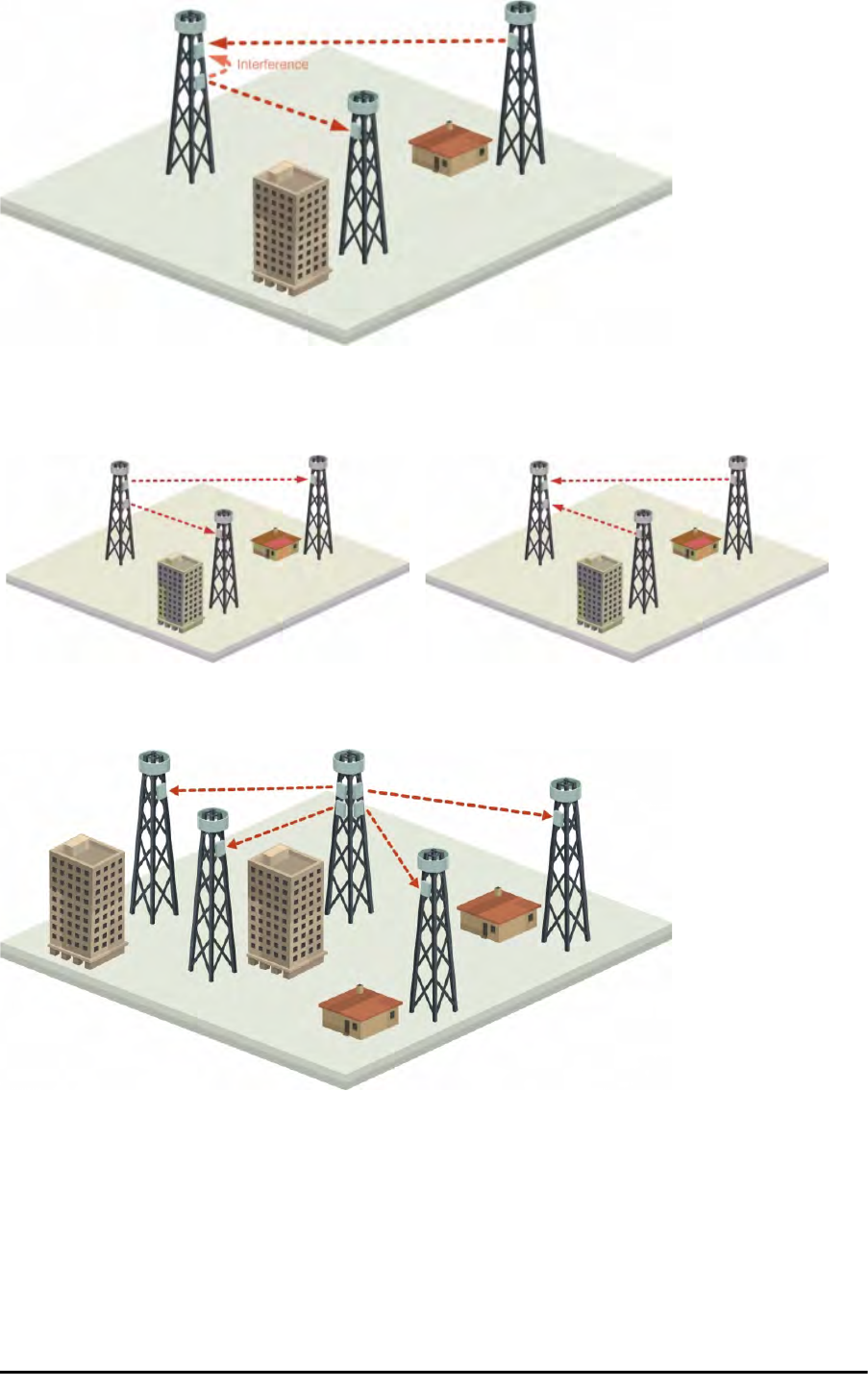
What is Hub Site Synchronization? Chapter 10
RADWIN 2000 User Manual Release 2.5.40 10-2
Figure 10-1: Interference caused by collocated units
Adding HSS removes interference as shown in the next two figures:
Figure 10-2: Collocated units using Hub Site Synchronization (1)
Figure 10-3: Collocated units using Hub Site Synchronization (2)
The units are connected to each other with HSS cables and HSS Distribution Units.
One of the radios in the site is defined as HSS Master and generates synchronization pulses.
The other collocated radios in the site - the HSS Clients, are connected to the HSS Master and
synchronize their transmission to the pulses. An HSS Client can be configured to work in one
of two modes:
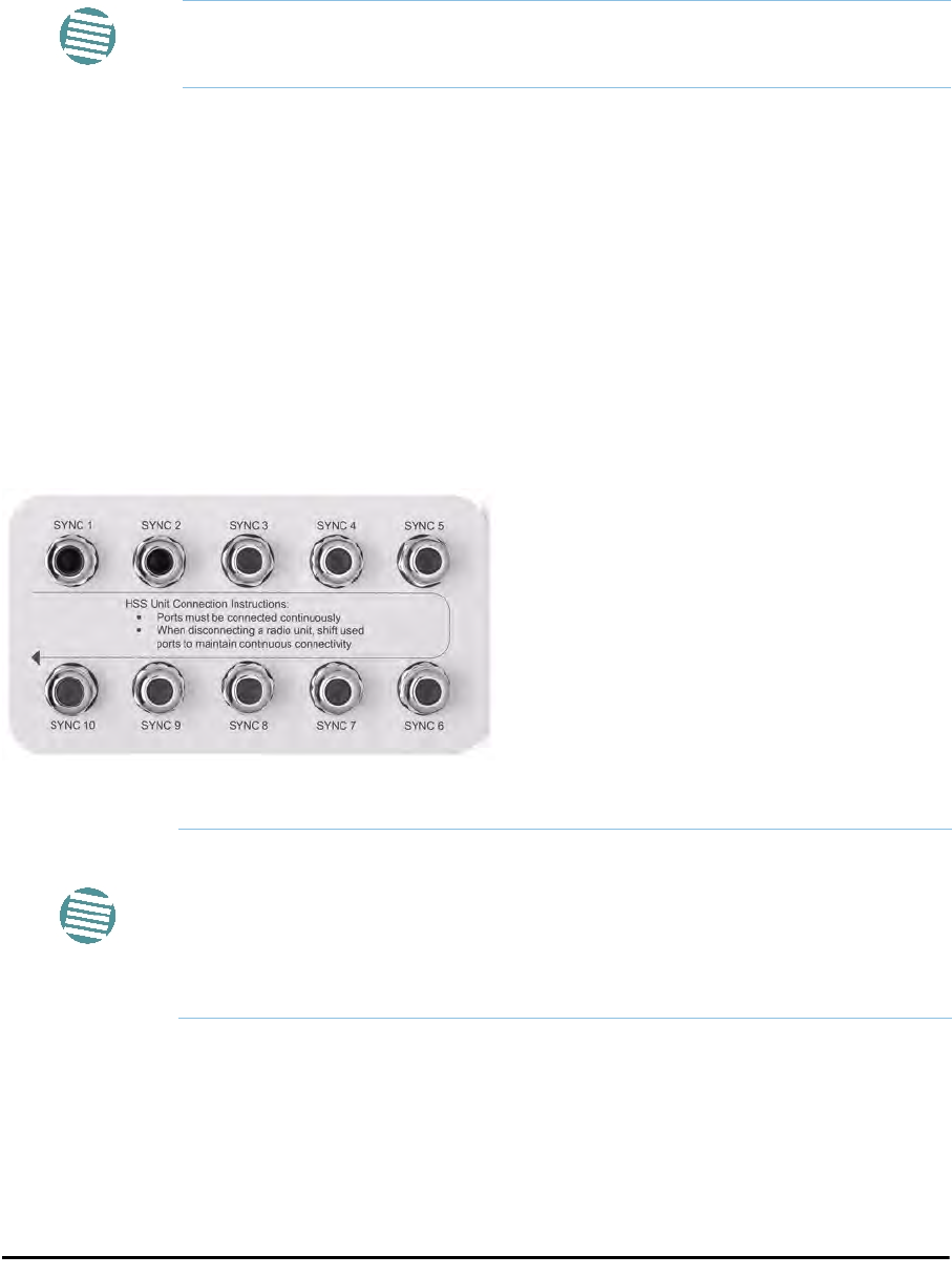
Hardware Installation Chapter 10
RADWIN 2000 User Manual Release 2.5.40 10-3
•HSS Client-Continue Transmission (HSC-CT): If the unit loses synchronization
with the HSS Master, the link remains active. However, without synchronization pulses,
it is possible that this unit will cause interference.
•HSS Client-Disable Transmission (HSC-DT): If the unit loses synchronization with
the HSS Master, the link is dropped until the synchronization pulses resume. This set-
ting prevents the unit from causing interference.
The remote ODUs that are not located at the hub site, are called Independent Units.
Hardware Installation
Connecting an HSS Unit
A single HSS unit supports up to ten collocated ODUs. In addition to each unit being con-
nected to its IDU or PoE device, the collocated unit has an additional cable that is connected
to the HSS Unit. The HSS Unit is a compact, weatherproof (IP67) connector box that is
installed on the same mast as the ODUs. All collocated units connect to this box using CAT-5e
cable. Cables in prepared lengths are available for purchase.
The HSS unit is supplied with ten protective covers; any port not in use must be closed with a
protective cover.
Figure 10-4: HSS Interconnection Unit
To connect an ODU to an HSS unit:
1. Unscrew the protective cover from the port marked SYNC 1.
2. Connect the RJ-45 connector from one end of the prepared CAT-5e cable to SYNC 1.
3. Connect the other end of the CAT-5e cable to the ODU connector labeled SYNC.
Note
WinLink 1000 radios used as independent units do not require HSS
hardware.
Note
• For a single HSS unit, ensure that the collocated units are connected
in sequence from SYNC 1. If an ODU is removed from the hub site,
then all remaining ODUs must be reconnected to maintain the con-
nectivity.
• You may cascade (daisy-chain) two or more HSS Units with an HSS
cable. The method is described in detail below.
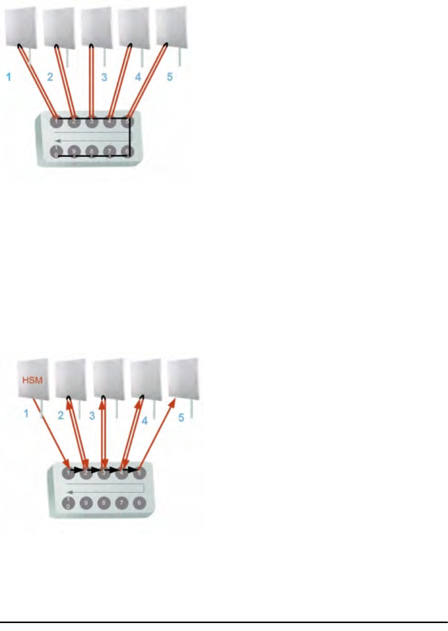
Using a Single HSS Unit Chapter 10
RADWIN 2000 User Manual Release 2.5.40 10-4
4. Tighten the protective seal that is on the prepared cable over the RJ-45 connector.
5. Repeat for all ODUs that are to be collocated at the hub site. The next ODU to be
connected is inserted in SYNC 1, SYNC 2, followed by SYNC 3 and so on.
Using a Single HSS Unit
Figure 10-5: HSS Wiring schematic
The wiring, as shown in Figure 10-5 is self explanatory. The Sync signal path is less self evi-
dent. If we set ODU 1 (on SYNC 1) to HSS Master, then the Sync signal path is as shown in
Figure 10-6. The signal travels from ODU 1 to SYNC 1, from SYNC 1 to SYNC 2, from SYNC
2 to ODU 2 and back again. The back and forth paths repeat for the second to fourth ODU,
from left to right. The signal exits the HSS unit at SYNC 5 and terminates in ODU 5.
The choice of the ODU on SYNC 1 as HSS master is not mandatory, but is good practice. If for
example we were to use ODU 3 as HSS master, the Sync signal path would be ODU 3 to SYNC
3, then left and right to SYNC 2 and SYNC 4. It would then propagate to ODUs 2 and 4, termi-
nating at both ODUs 1 and 5.
Figure 10-6: HSS sync signal path with ODU 1 as HSS Master
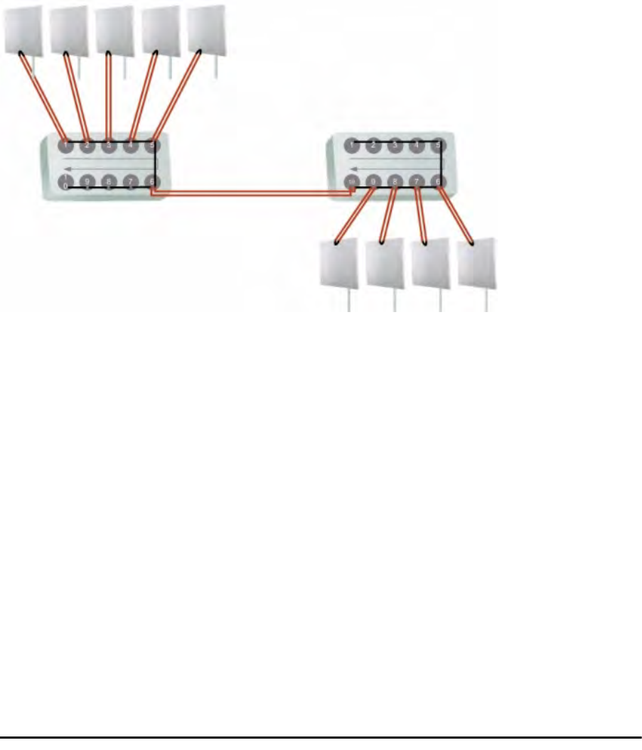
Using More than One HSS Unit Chapter 10
RADWIN 2000 User Manual Release 2.5.40 10-5
Using More than One HSS Unit
In a large collocation site, several HSS units may be cascaded (daisy-chained) subject to the
following conditions:
Condition 1: Cabling Sequence
1. Up to nine ODUs may be connected to the first HSS unit using HSS ports SYNC 1, SYNC 2,
SYNC 3,... up to SYNC 9 in order without leaving empty ports.
2. The next available SYNC port of the first HSS unit should be connected to SYNC 10
of the second HSS unit as shown in Figure 10-7. In the illustration, the next
available port on the first HSS unit is SYNC 6.
3. The second HSS unit may be filled out with up to nine more ODUs in reverse
order. That is, connect SYNC 9, SYNC 8, SYNC 7... as shown in Figure 10-7.
Figure 10-7: Cascading two HSS units
4. To add a a further HSS unit: Connect the next available SYNC port from the second
HSS unit in descending order (SYNC 5 in Figure 10-7) to SYNC 1 of the third
HSS unit.
5. ODUs are connected to the third HSS unit from SYNC 2 as shown in Figure 10-8,
in ascending order:

HSS Error Notification Chapter 10
RADWIN 2000 User Manual Release 2.5.40 10-6
Figure 10-8: Cascading three HSS units
6. If further ODUs are required, observe the convention that additional even
numbered units are populated in descending order from SYNC 9 and odd
numbered HSS units are populated in ascending order from SYNC 2.
Condition 2: Total HSS Cable Length
The total path of the HSS sync pulse must not exceed 300m. This applies no matter how
many HSS units are used. To illustrate the method for calculating the sync pulse path length
we show three examples. For our purpose, let:
Lmn denote the length of the ODU-HSS unit cable at SYNC n on HSS unit m
Hm be the length of the cable joining HSS unit m to HSS unit m+1
One HSS unit with five collocated ODUs
Two cascaded HSS units as shown in
Figure 10-7
Three cascaded HSS units as shown in
Figure 10-8
HSS Error Notification
In the event of an HSS installation fault, the ODU will sound a beep pattern according to the
following chart, also printed on the ODU product label:
Note
If an ODU is disconnected from an HSS unit, then all remaining ODUs must
be moved up or down to maintain the connectivity.
PathLength L11 2L12 2L13
+2L14 L15
+++=
PathLength L11 2L12 2L13 2L14
+
2+
L15
+
H12L29 2+L28 2+ L27
L26
+
+
++
=
PathLength L11 2L12 2L13 2L14
+
2+
L15
+
H12L29 2+L28 2+ L27
2L26
+
H22L32 2L33 2L34 L35
+++
+
++ +
+
=

ODU/HSS Unit Connection Pinout Chapter 10
RADWIN 2000 User Manual Release 2.5.40 10-7
Figure 10-9: ODU beep for HSS Error
ODU/HSS Unit Connection Pinout
Radio Frame Pattern (RFP)
A Radio Frame Pattern (RFP) is the cycle duration of transmit and receive of the air-frame.
Without HSS
When selecting TDM or Ethernet services, the system automatically and transparently
chooses the optimal RFP. When TDM and Ethernet services are configured, the RFP is opti-
mized for TDM.
RFP and HSS
When HSS is used, the RFP for the collocated radios must be selected manually.
Both WinLink 1000 and RADWIN 2000 use the Time Division Duplex (TDD) mechanism.
Under HSS, TDD enables synchronization of transmission for the collocated units as shown in
Figure 10-10:
Table 10-1: ODU/HSS Unit Connection Pinout
Color ODU
RJ-45 HSS UNIT
RJ-45
White/Green 1 1
Green Not connected
White/Orange
Orange 6 6
Blue 4 4
White/Blue 5 5
White/Brown 7 7
Brown 8 8
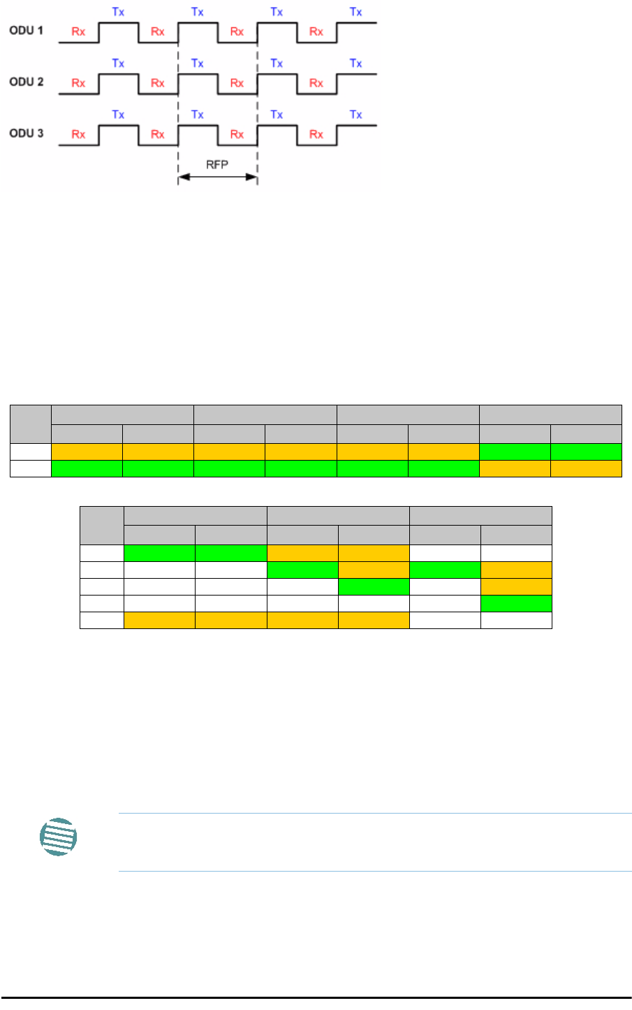
RFP: General Radio Frame Pattern Chapter 10
RADWIN 2000 User Manual Release 2.5.40 10-8
Figure 10-10: Radio Frame Pattern
Five RFP types (A to E) are available. Under HSS the RFP must be configured by the user
depending on the type of the radio products, services and channel bandwidth in accordance
with the Table 10-2 and Table 10-3.
The tables describe the efficiency of the air interface according to the RFP type, radio prod-
ucts mix, services and channel bandwidth. The tables may also be viewed in the RADWIN
Manager and in the Link Budget Calculator for both WinLink 1000 and RADWIN 2000. The
efficiency of the air interface will vary according to the product used.
Legend:
Best fit - optimal RFP choice for TDM and Ethernet services.
Available - available RFP for TDM and Ethernet services, but not optimal.
N/A - service unavailable
Select the RFP that gives you the Best Fit or Available for required system services and
select the channel bandwidth accordingly.
RFP: General Radio Frame Pattern
When setting the RPF, the following considerations should be borne in mind:
• When synchronizing RADWIN 2000 units you must use RFP B or E
Table 10-2: Radio Frame Pattern Table - RADWIN 2000
RFP 40 MHz 20 MHz 10 MHz 5 MHz
TDM Ethernet TDM Ethernet TDM Ethernet TDM Ethernet
BAvailable Available Available Available Available Available Best fit Best fit
EBest fit Best fit Best fit Best fit Best fit Best fit Available Available
Table 10-3: Radio Frame Pattern Table - WinLink 1000
RPF 20 MHz 10 MHz 5 MHz
TDM Ethernet TDM Ethernet TDM Ethernet
ABest fit Best fit Available Available N/A N/A
BN/A N/A Best fit Available Best fit Available
CN/A N/A N/A Best fit N/A Available
DN/A N/A N/A N/A N/A Best fit
EAvailable Available Available Available N/A N/A
Note
The RFP must be the same for each link within the collocated system.
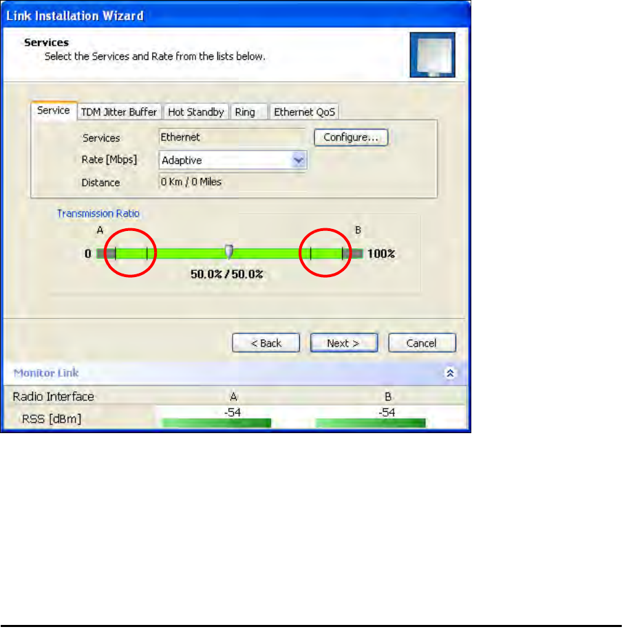
RFP: RADWIN 2000 Considerations Chapter 10
RADWIN 2000 User Manual Release 2.5.40 10-9
• If you mix RADWIN 2000 and WinLink 1000 units in a collocated site, you must use
RFP B or E
• Selection of the RFP influences the capacity, latency and TDM quality
• RFP influences capacity and latency. Jitter buffer configuration can be used to set the
TDM quality (see the User Manual, Chapter 5, TDM Services selection)
• Using the Link Budget Calculator, you can see the affect of the RFP on the Ethernet
throughput.
RFP: RADWIN 2000 Considerations
• The performance of RADWIN 2000 radios that operate with RFPs B or E can be seen
in the Link Budget Calculator.
• For RADWIN 2000 C series: If the HSS Master works in asymmetric Tx/Rx ratio, then
all other collocated RADWIN 2000 units must operate in the same Tx/Rx ratio. In this
case the ratio will be fixed and not automatic-adaptive.
• Installation/Configuration considerations: If you are using RADWIN 2000 C master
and RADWIN 2000 clients, the Services and Rates dialog will look like this:
Figure 10-11: Services and Rates - RADWIN 2000 C master, RADWIN 2000 clients
• The circled areas should not be used. Using those areas, you may loose the collocated
link with the longest distance between sites. If you do move the slider into a circled
area, you will receive a popup warning:
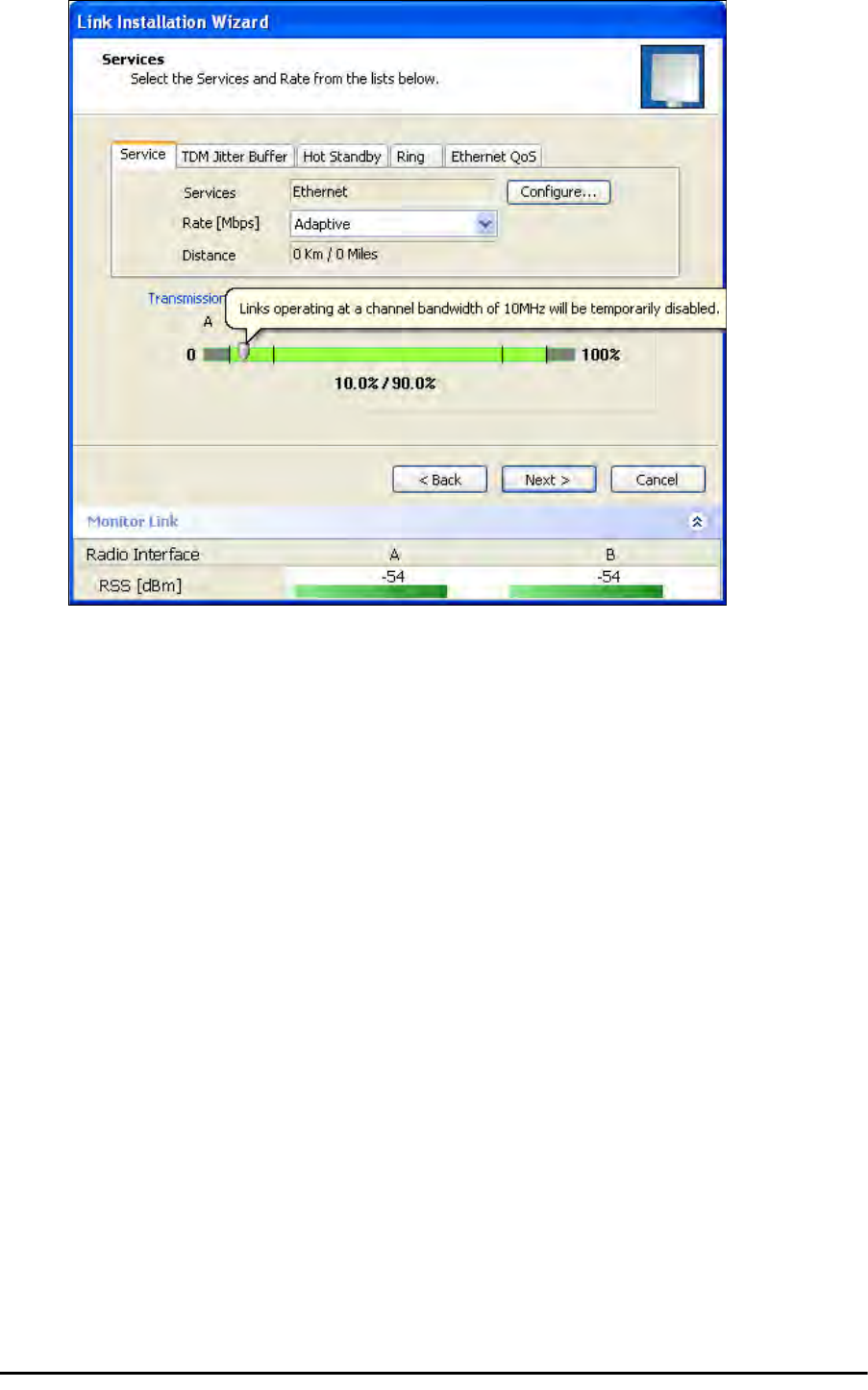
RFP: RADWIN 2000 Considerations Chapter 10
RADWIN 2000 User Manual Release 2.5.40 10-10
Figure 10-12: Services and Rates - RADWIN 2000 C master, RADWIN 2000 clients - Extreme
asymmetric allocation
By restricting one direction into the restricted area, the more distant sites may not
even be able to sustain the link much less send or receive data.
• Asymmetric Allocation and Collocation: If the link is collocated, the use of Asymmetric
Allocation is limited.
The effective available range for Asymmetric Allocation (between the two circled tick
in Figure 10-11) is primarily determined by three factors:
• The RFP in use (B or E)
• Channel Bandwidth
•Link distance
The first two parameters are entered during Link
Installation/Configuration.
• Possible scenarios are shown in Table 10-4.Whenever Asymmetric Allocation is avail-
able, it is static for all traffic conditions.

RFP: WinLink 1000 Considerations Chapter 10
RADWIN 2000 User Manual Release 2.5.40 10-11
RFP: WinLink 1000 Considerations
• When WinLink 1000 radios are collocated with RADWIN 2000 radios using HSS, all
radios must use RFP B or E.
• The performance of WinLink 1000 radios that operate with these RFPs can be seen in
the Link Budget Calculator.
• The choice of the unit to be the HSS master is a matter of convenience. There is no
technical reason to prefer a WinLink 1000 over a RADWIN 2000 as HSS master or vice
versa. It is however, recommended that you use the RADWIN 2000 as master, since it
will enforce the correct RFP on the other collocated units.
The following list summarizes the effect of using RFP B or E on WinLink 1000 radios. These
effects should be taken into consideration when planning new installations:
• Channel bandwidth 5 MHz is available under RFP E but is only supported for WinLink
Access products
• For products supporting a maximum throughput of 18.1 Mbps, the maximum Ethernet
throughput is 14.5 Mbps at 20 MHz channel bandwidth and 9.3 Mbps at 10 MHz chan-
nel bandwidth
• For products supporting maximum throughput of 22.5 Mbps, the maximum Ethernet
throughput is 21.4 Mbps at the 20 MHz channel and 9.3 Mbps at 10 MHz channel
bandwidth
Table 10-4: Asymmetric Allocation with Collocated Links - Scenarios
HSS Master HSS Client Scenario: If you try to... Result Remarks
RADWIN 2000
WinLink 1000
Change master to
asymmetric allocation
Link down Reversion to 50/50 restores link
RADWIN 2000
• Releases prior to
2.4 - Link down
• Release 2.4 later
(RADWIN 2000 PDH
and RADWIN 2000
L series) - Link
down
• Release 2.4 and
later (RADWIN
2000 C and RAD-
WIN 2000 Xseries) -
TDM services
stopped, link set to
transmission ratio
of master
Release 2.4 and later (RADWIN
2000 C and RADWIN 2000
Xseries) - Asymmetric Allocation
slider visible but cannot be
changed
RADWIN 2000
WinLink 1000
RADWIN 2000 Change client to
asymmetric Asymmetric Allocation slider
not displayed You cannot do this
WinLink 1000
WinLink 1000
RADWIN 2000 Change client to
asymmetric Asymmetric Allocation slider
not displayed You cannot do this
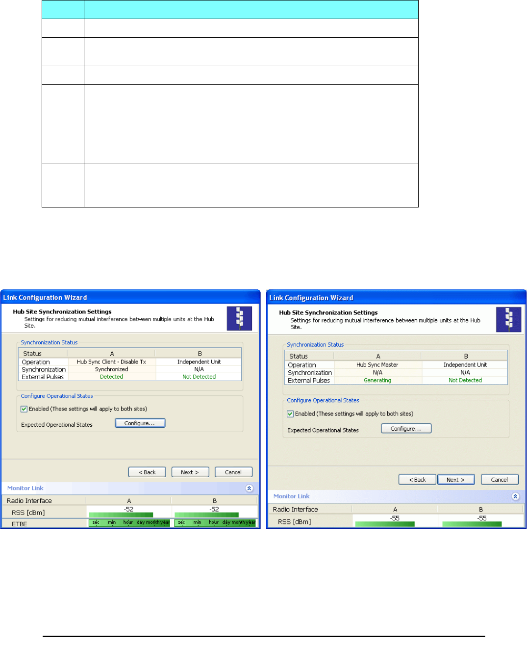
HSS Status LED on the IDU-C and New Style IDU-E Chapter 10
RADWIN 2000 User Manual Release 2.5.40 10-12
HSS Status LED on the IDU-C and New Style IDU-E
The IDU-C and IDU-E have a front panel HSS status LED:
Link Configuration and HSS
For WinLink 1000 HSS-enabled units and all RADWIN 2000 units, the Hub Site Synchroniza-
tion Settings dialog box appears in both the Link Installation and Configuration Wizards.
Figure 10-13: HSS Settings: Left - WinLink 1000
client
, Right - RADWIN 2000
master
The Synchronization Status dialog box displays the current status of each side of the link.
•Operation: Type of unit
• Hub Sync Master (HSM)
• Hub Sync Client - Disable Transmission (HSC-DT)
Table 10-5: IDU-C and New Style IDU-E Front Panel LEDs for HSS
Color Function
Green This ODU is HSS master, generating signal, and HSS Sync is OK
Blinking
Green This ODU is a HSS client and in Sync
Red HSS not operational due to improper signal detection. This ODU is not transmitting
Orange
HSS is operational. One of the following conditions apply:
• This ODU is a master that is generating signals and detecting signals
• This ODU is a master that is generating signals but detected improper signals
• This ODU is a client “Continue Tx” but is not detecting signals
• This ODU is a client “Disable Tx” and is detecting signals from multiple sources
All orange cases transmit.
Off HSS is not activated
HSS is not supported (WinLink 1000 only)
Disconnection between ODU and IDU

Link Configuration and HSS Chapter 10
RADWIN 2000 User Manual Release 2.5.40 10-13
• Hub Sync Client - Continue Transmission (HSC-CT)
• Independent Unit
•Synchronization:
• N/A- for Master or Independent Units
• Synchronized - for Hub Site Clients
• Not Synchronized - for Hub Site Clients
• External Pulses:
To configure the Operational States of the Hub Site unit
1. Click the Enabled check box
2. Click the Configure button
The Hub Site Configuration dialog box with the current status of the ODUs is dis-
played.
3. Select the type of unit configuration from the drop-down list.
4. Select the appropriate RFP radio button. Some RFP options may be disabled depend-
ing on the bandwidth previously selected.
Note
Continue Transmission is intended to work if there is no HSM pulse. If a
wrong HSM pulse is detected, a WinLink 1000 will resync, adapting to the
HSM RFP and continue whereas RADWIN 2000 may stop.
Table 10-6: External Pulse Status
HSS Sync Status Meaning Color code
Generating ODU is HSM and generates the
sync pulse
Green
Detected ODU is HSC and detects the
sync pulse
Not detected ODU is independent
Generating and detected HSM, but other HSM present
Orange
Generating and
Improperly Detected
RADWIN 2000 ODU is HSM,
but but detects a WinLink 1000
HSM signal that is not RFP E
Not detected HSC but no HSM present
Improperly detected
HSC but HSM pulse doesn’t fit
the HSC as configured. Occurs
only for RADWIN 2000, which
stops transmitting.
Red
Note
Take care to avoid incorrect configuration of bandwidth, RFP or to set
multiple Hub Sync Masters, as system interference can occur. RADWIN
Manager provides error messages and tool tips if the system is configured
with mismatches.
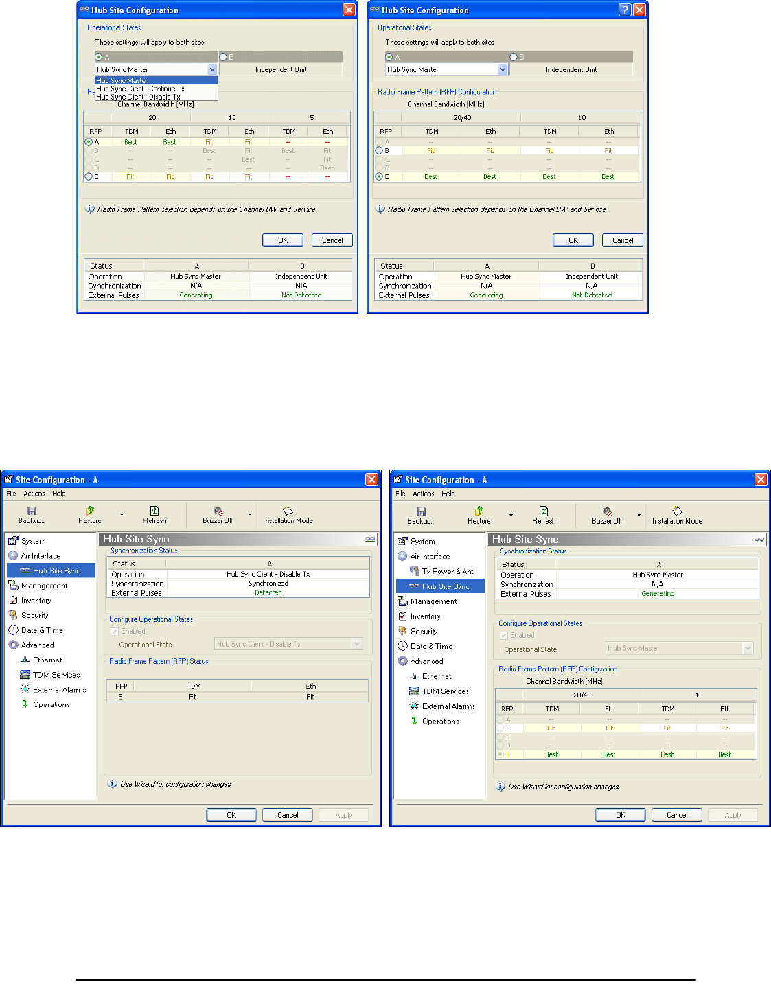
Site Configuration and HSS Chapter 10
RADWIN 2000 User Manual Release 2.5.40 10-14
Figure 10-14: Hub Site Configuration dialog - Left WinLink 1000, right RADWIN 2000
Site Configuration and HSS
For units that support HSS, the Hub Site Sync option appears in the Air Interface section and
displays the current HSS of the unit. Configure the unit from the Link Configuration Wizard
according to the procedure described above.
Figure 10-15: Site Configuration: HSS - Left - WinLink 1000 client, Right - RADWIN 2000
mas-
ter
For WinLink 1000 units without HSS support, Figure 10-16 is displayed instead of
Figure 10-15:

Site Configuration and HSS Chapter 10
RADWIN 2000 User Manual Release 2.5.40 10-15
Figure 10-16: HSS Not Supported

RADWIN 2000 User Manual Release 2.5.40 11-1
Chapter 11
Using the RADWIN GSU
What is it for
The GPS-based synchronization unit (GSU) is designed to handle inter-site interferences
under large-scale deployment scenarios.
The GSU is an outdoor unit consisting of a standard WinLink 1000 enclosure, a GPS antenna
and a PoE device.
The GSU is connected to the HSS Unit using a standard HSS cable. It synchronizes the trans-
mission timing of multiple Hub-Sites to the same clock source thus eliminating mutual inter-
ference.
GSU Functionality
The GSU receives a synchronization signal from the GPS once per second. It distributes a
RADWIN proprietary synchronization signal to all other ODU units using the RS422 protocol
and the standard HSS mechanism, where the GSU acts as an HSM unit.
When the GSU doesn’t receive a synchronization signal from the GPS for 30 seconds, it moves
automatically to Self-Generation mode and acts as a regular HSM unit, until the GPS recovers.
Typical GSU Scenarios
Independent Distributed Sites
In the scenario of Figure 11-1, we have multiple independent collocated sites, which may
interfere with each other. To meet this situation, we coordinate all of them using the GSU as
shown.
The GSU functions like “wide area HSS unit”, ensuring that all participating radios at the loca-
tions marked GSU each transmit and receive at the same time.
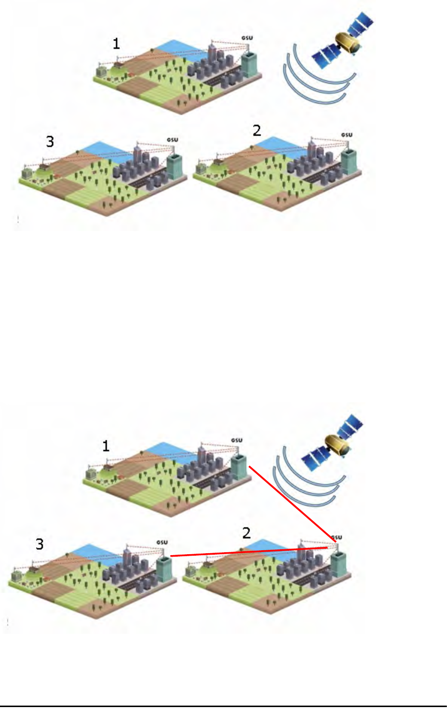
Multiple Distributed Sites with Communication Chapter 11
RADWIN 2000 User Manual Release 2.5.40 11-2
pendent dis tributed sites
Figure 11-1: GSU Scenario - Independent distributed sites
Multiple Distributed Sites with Communication
What happens if, in Figure 11-1, the GSU towers themselves have radios communicating as
shown in Figure 11-2?
Consider GSU 1 and GSU 2: Both collocated towers transmit and receive simultaneously. How-
ever, the radios communicating at GSU 1 and GSU 2 must transmit and receive in turn accord-
ing to the scheme in marked “Normal Phase” in Figure 11-3. This is an impossible situation,
if all the links must send and receive together. It is further complicated by adding a third and
further sites as shown.
Figure 11-2: GSU Scenario - Communicating distributed sites
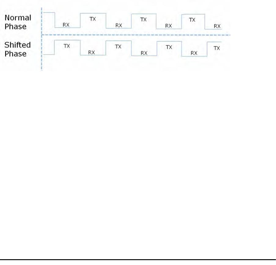
Cascaded Sites using Shifted Phase Transmission Chapter 11
RADWIN 2000 User Manual Release 2.5.40 11-3
Cascaded Sites using Shifted Phase Transmission
The solution offered here is not a “universal cure”. The following conditions are necessary, but
in any specific case may not be sufficient:
• The GSU sites (marked 1, and 3 above) are sufficiently far apart as to ensure that
there is no mutual interference between communicating sites (1-2 and 2-3 above)
• There should be no interference between non-communicating sites (1 and 3 above).
To see how it works, we use Figure 11-2. The GSU towers are numbered and marked for
cascading, 1-2 and 2-3. There should
not
be a link between 1 and 3.
The GSU can synchronize the TDD timing of several sites enabling the cascading of consecu-
tive links without mutual interference.
To use cascading, the TDD timing of the even-ordered links (GSU 2 above) must be “shifted”
(Shifted Phase) and odd-ordered links (GSU 1 and GSU 3 above) must be “unshifted” (Normal
Phase). The phase shift is half of the Radio Frame Duration (RFD) from the chosen RFP. The
scheme is shown in Figure 11-3.
Since the GSU is always HSS master (HSM), at each GSU location, the GSU can “force” the
synchronization of its collocated radios. By half RFD shifting, alternate collocated sites can
talk to each other.
Figure 11-3: Phase shifted transmission - phase shift is 1/2 the RFD
Choice of normal or shifted phase is configurable per GSU using the RADWIN Manager.
GSU Redundancy
The GSU is designed to support redundancy, improving the robustness of a GSU based topol-
ogy.
In redundancy mode, two GSUs are installed at the same HSS site. One of them self-config-
ures to generate HSS sync signals. We will call it the Primary unit. The other one, the Second-
ary unit remains dormant merely polling the first GSU. If the Primary GSU fails, then the
Secondary GSU becomes active immediately. If the Primary unit becomes active again, it
remains dormant, reversing the original roles. The choice of the Primary GSU is random and
of no significance.
If the Primary GSU fails, and then the Secondary GSU also fails to receive sync signals from
its GPS, then it moves to self-generation HSM mode like an ordinary HSM ODU until its GPS
recovers.

GSU Kit Contents Chapter 11
RADWIN 2000 User Manual Release 2.5.40 11-4
Figure 11-4: Make the GSUs the first two collocated units
Redundancy switching is completely transparent to the GSU-managed links.
GSU Kit Contents
The GSU package includes:
•1 x GSU
• 1 x Mounting Kit
•1 x GPS Antenna
• 1 x GPS Antenna Mounting Kit
• 1 x RF Cable, 1.5m
•CD
GSU Installation
Overview
The GSU uses the same container and cabling as a WinLink 1000 unit.

Preparing the GSU for Use Chapter 11
RADWIN 2000 User Manual Release 2.5.40 11-5
Figure 11-5: General GSU configuration
In that respect, all of the considerations of Chapter 3, Chapter 17 and Chapter 18 of the
use Manual apply to the GSU.
It may be configured using the regular RADWIN Manager or Telnet.
Preparing the GSU for Use
Use the method of Chapter 19, Preloading an ODU with an IP Address to change the IP
address from the default (10.0.0.120). In the example screen captures below, we use
192.168.222.20 with Subnet Mask 255.255.252.0.
Mounting the GSU
Mount the GSU and antenna. Ensure that its ODU port connected to its PoE device and the
HSS cable is connected to the HSS unit as shown. The external LAN port of the PoE device is
connected to the managing computer. If you are accessing the GSU through a network it is
essential that you use the IP preloading method. The default IP address may be inaccessible
and you may not use the Local Connection method over a network.
Configuring the GSU
Getting Started
To configure the GSU, you log on to it, exactly as in Chapter 4.
The GSU Main Window
Here is the main window for GSU configuration:
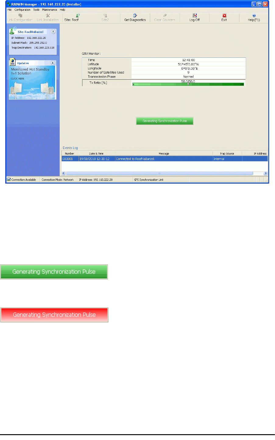
Configuring the GSU Chapter 11
RADWIN 2000 User Manual Release 2.5.40 11-6
Figure 11-6: GSU Main widow at startup
The top five items in the GSU Monitor panel are taken from a satellite. The transmission
Phase may be Normal as shown or Shifted. It purpose, together with the Tx Ratio bar, will
be explained below.
The Status Box
Under normal operating conditions, it will be green as shown, indicating that it is synchro-
nized with a satellite.
If satellite synchronization is lost, then the GSU will function as an independent HSM and the
status box will change color:
The Main Menu
The main menu is a subset of the main menu applicable to the WinLink 1000. Notice that
there are no Installation or Configuration wizards. Such configuration as is necessary is car-
ried out using a modified version of Site Configuration for WinLink 1000.
Similarly, the Tool bar is a subset of that applicable to the WinLink 1000.
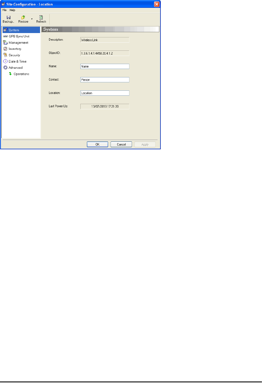
Configuring the GSU Chapter 11
RADWIN 2000 User Manual Release 2.5.40 11-7
Using Site Configuration for the GSU
Site Configuration: System
Here is the opening window for Site Configuration:
Figure 11-7: Site Configuration: System
It is similar to that of the WinLink 1000.
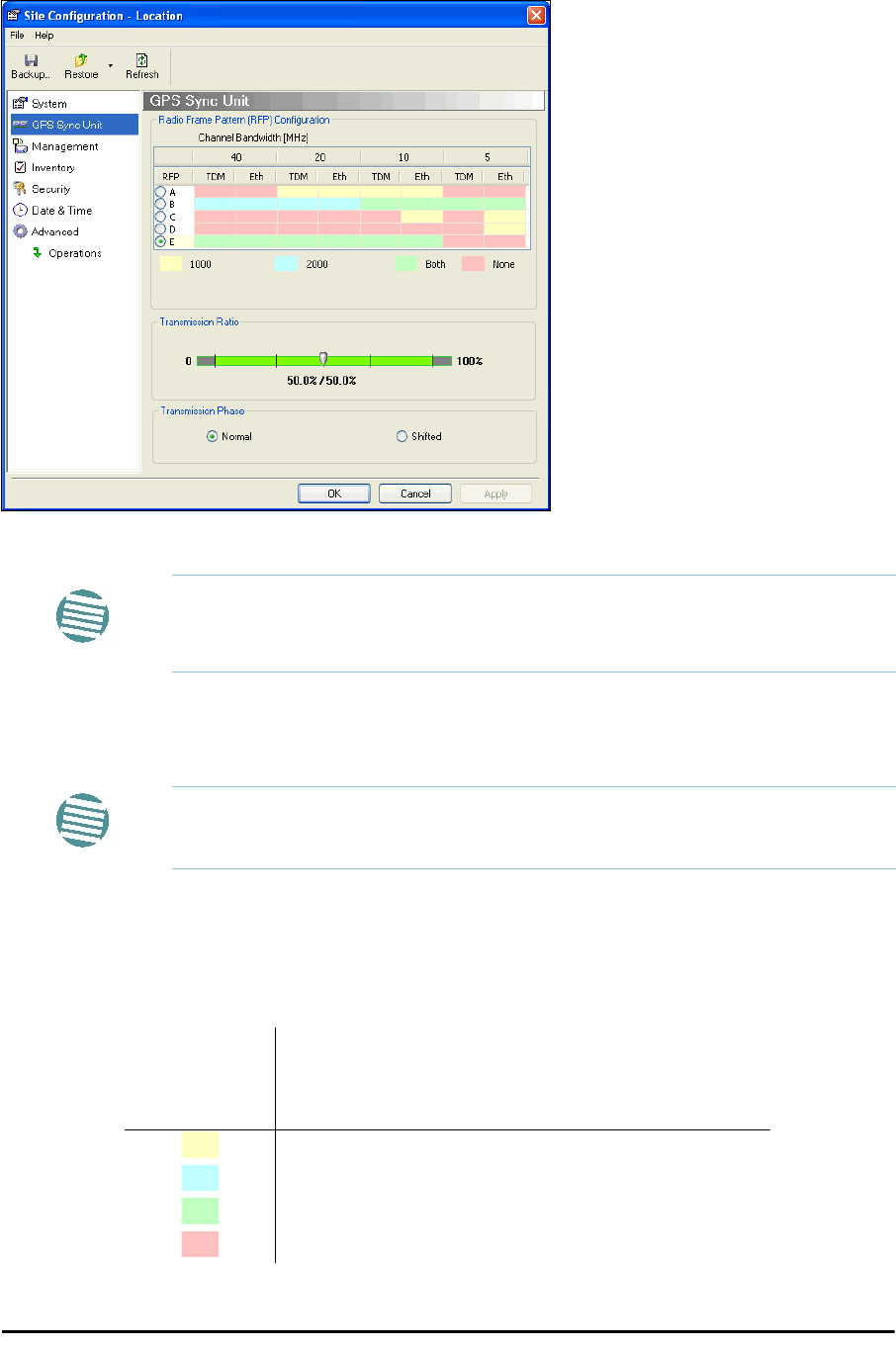
Configuring the GSU Chapter 11
RADWIN 2000 User Manual Release 2.5.40 11-8
Site Configuration: GPS Sync Unit
This window is the main GSU configuration tool:
Figure 11-8: Site Configuration: GPS Sync Unit
1. Setting the RFP for HSS
The GSU is automatically configured as HSS Master (HSM).
If the hub site consists only of WinLink 1000 units, then any suitable RFP may be chosen.
If there are one or more RADWIN 2000 units, you must use RFP B or E.
The permitted RFPs are also dependent on channel bandwidth and are color coded as fol-
lows:
Note
The 1000 and 2000 labels refer to WinLink 1000 and RADWIN 2000 radios,
respectively. The actual annotation seen may vary, but the intention should
be clear.
Note
Ensure that no other collocated ODU is configured as HSM.
You May use RFP/
Channel
Bandwidth
combinations with
this color
For these collocated radios
WinLink 1000 only
RADWIN 2000 only
WinLink 1000 and RADWIN 2000 together
None - unavailable