Radwin RW2025 Outdoor radio unit operating in the 2.5-2.7 GHz (BRS) band User Manual STW
Radwin Ltd. Outdoor radio unit operating in the 2.5-2.7 GHz (BRS) band STW
Radwin >
Contents
- 1. User Manual Part 1
- 2. User Manual Part 2
User Manual Part 2
Configuring the GSU Chapter 11
RADWIN 2000 User Manual Release 2.5.40 11-8
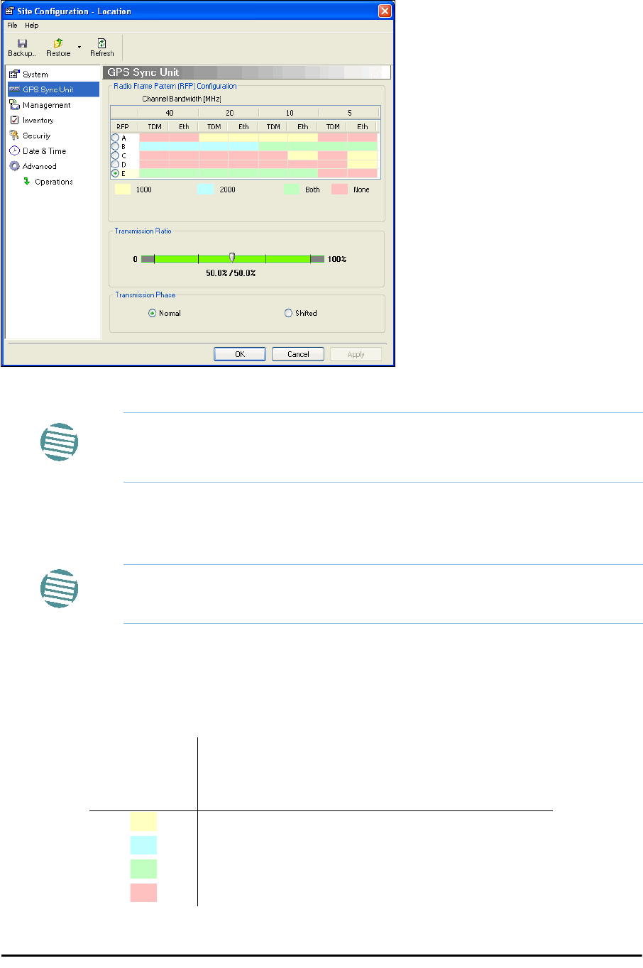
Site Configuration: GPS Sync Unit
This window is the main GSU configuration tool:
Figure 11-8: Site Configuration: GPS Sync Unit
1. Setting the RFP for HSS
The GSU is automatically configured as HSS Master (HSM).
If the hub site consists only of WinLink 1000 units, then any suitable RFP may be chosen.
If there are one or more RADWIN 2000 units, you must use RFP B or E.
The permitted RFPs are also dependent on channel bandwidth and are color coded as fol-
lows:
Note
The 1000 and 2000 labels refer to WinLink 1000 and RADWIN 2000 radios,
respectively. The actual annotation seen may vary, but the intention should
be clear.
Note
Ensure that no other collocated ODU is configured as HSM.
You May use RFP/
Channel
Bandwidth
combinations with
this color
For these collocated radios
WinLink 1000 only
RADWIN 2000 only
WinLink 1000 and RADWIN 2000 together
None - unavailable
Configuring the GSU Chapter 11
RADWIN 2000 User Manual Release 2.5.40 11-9
There is a further restriction: If there are two distributed sites transmitting to each other,
they must both use the same RFP. This requirement, together with use of shifted transmis-
sion phase (item 3 below), ensures that communicating distributed sites to not interfere
with each other by transmitting simultaneously.
Two GSU managed sites transmitting with shifted transmission phase and using the same
RFP, transmit one half a RFD apart (see Figure 11-3 above).
2. Setting the Tx Transmission Ratio
Since the GSU is always HSM, it must be able to cater for hub site RADWIN 2000 C based
links. (See the RADWIN 2000 User Manual, Chapter 5). If you use asymmetric allocation,
shifted transmission phase becomes unavailable and you cannot “cascade” links as
described in step 1.
3. Choosing the Transmission Phase
Chose the Transmission Phase in accordance with considerations in step 1 above. If you
choose Shifted Phase then the Asymmetric Ratio selector is disabled.
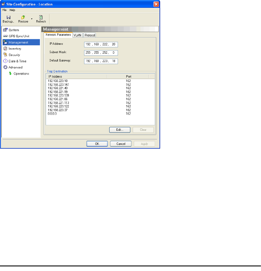
Site Configuration: Management
Figure 11-9: Site Configuration: Management
Here you set the GSU IP address, subnet mask and gateway. You also set trap addresses
here. It is identical to the corresponding panel for WinLink 1000.
Configuring the GSU Chapter 11
RADWIN 2000 User Manual Release 2.5.40 11-10
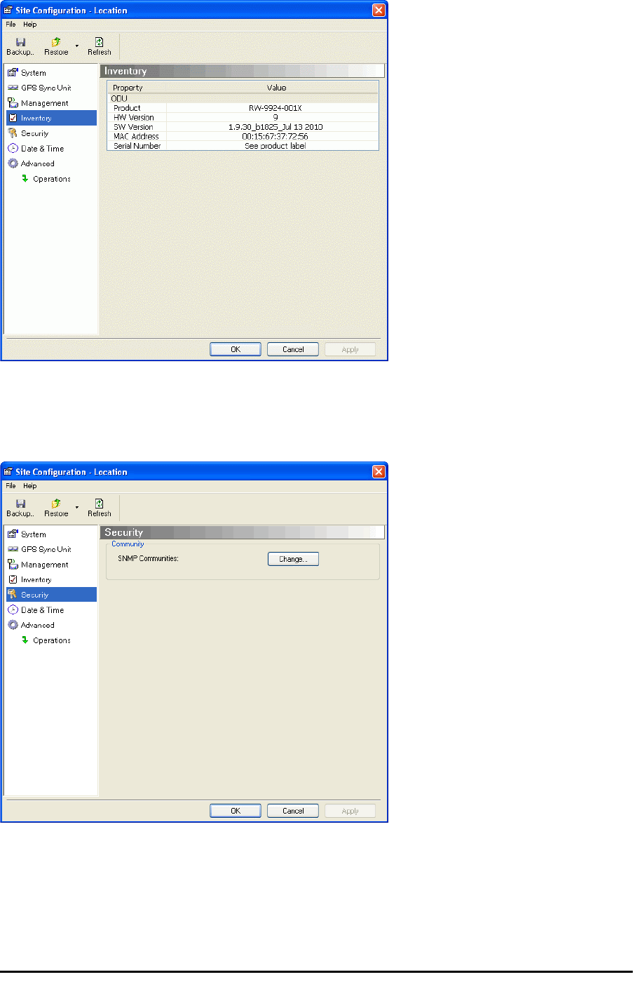
Site Configuration: Inventory
Figure 11-10: Site Configuration: Inventory
Site Configuration: Security
You can only change the SNMP Community stings:
Figure 11-11: Site Configuration: Security
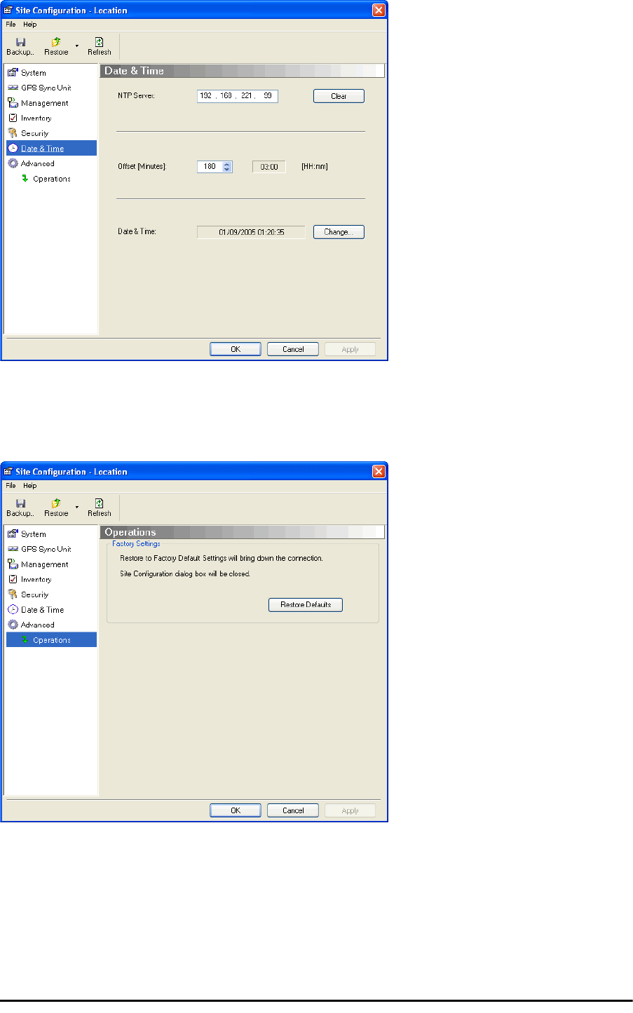
Site Configuration: Date and Time
ODU Recent events, alarms and traps are time-stamped from the time method chosen here
(NTP, managing computer, ODU default).
Configuring the GSU Chapter 11
RADWIN 2000 User Manual Release 2.5.40 11-11
Figure 11-12: Setting the date and time for trap reporting
Site Configuration: Operations
The only available action here is Restore System Defaults:
Figure 11-13: Site Configuration: Operations

GSU Preferences Chapter 11
RADWIN 2000 User Manual Release 2.5.40 11-12
GSU Preferences
The Preferences window adds a new tab for the GSU:
Figure 11-14: Site Configuration: Operations
You may chose the units for latitude/longitude coordinates.
GSU Monitoring and Diagnostics
The monitoring and diagnostic reports are similar to those of WinLink 1000.
GSU Telnet Support
To configure the GSU with Telnet, start a Telnet session, using
telnet <GSU_ipaddr>.
For example, if you run Telnet as follows,
telnet 192.168.222.20
you will be asked for a user name and password. You must log on with administrator privilege
under user name,
admin
and password
netman
.
The available commands are the same as for WinLink 1000 with the addition of four addi-
tional display commands and three additional set commands.
The additional display commands are
display rfp
display ratio
display tx_phase
display gpsinfo
The last one display gpsinfo, is the most interesting:
admin@192.168.222.20-> display gpsinfo
Current GPS time 102941.000

Software Update for GSUs Chapter 11
RADWIN 2000 User Manual Release 2.5.40 11-13
Current GPS latitude 51.500000
Current GPS N\S Indicator N
Current GPS longitude 0.000000
Current GPS E\W Indicator E
Current GPS number of satellites 09
Current GPS altitude 84.0
Command "display gpsinfo" finished OK.
The three additional set commands are
set rfp <index> (2-6)
set ratio <ratio>
set tx_phase <mode:1=normal,2=shifted>
Software Update for GSUs
All GSUs in a distributed site can be updated simultaneously. Use an IP list as described in
Chapter 15.

RADWIN 2000
Broadband Wireless Transmission System
USER MANUAL
RELEASE 2.5.40
Part 3: Advanced Installation
UM 2000-2540/02.11
RADWIN 2000 User Manual Release 2.5.40 12-1
Chapter 12
Monitored Hot Standby
Installation Procedure
What is a RADWIN Monitored Hot Standby
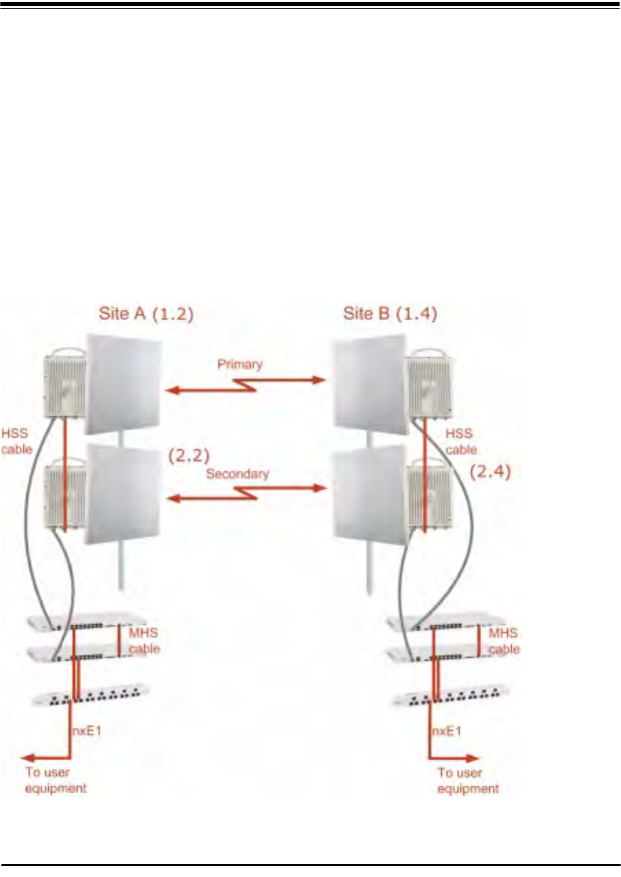
The RADWIN Monitored Hot Standby (MHS a.k.a 1+1) is a duplicated link set up as a primary
link and a secondary link in hot standby mode as shown in Figure 12-1 below.
Figure 12-1: RADWIN Monitored Hot Standby

What RADWIN MHS provides Chapter 12
RADWIN 2000 User Manual Release 2.5.40 12-2
RADWIN MHS provides redundancy and backup to TDM services. It is designed to provide
high reliability high-capacity Point-to-Point links. The RADWIN MHS is -
• Designed to provide redundancy and high reliability for carrier class operators
• Optimized for high capacity links operating in license-free bands
• A comprehensive solution providing protection against both equipment failure and loss
of air interface, by simple connectivity between a primary link and a secondary link
The main service redundancy features of the RADWIN MHS are –
• TDM service cut-over from the primary to the secondary link is completely automatic
• TDM service cut-over time no more than 50 ms
• Automatic restore to primary link as soon as it becomes available
• Support for up to sixteen TDM channels for RADWIN 2000 and four TDM channels for
WinLink 1000.
MHS is supported between -
• two WinLink 1000 links
• two RADWIN 2000 links
• a WinLink 1000 link and a RADWIN 2000 link.
What RADWIN MHS provides
Equipment Protection
Equipment protection is provided for the electrically-active network elements, ODU and IDU.
The primary IDU and the secondary IDU are connected by a cable to monitor failure and to
control protection switching. Switching time is less than 50ms.
When connecting two WinLink 1000 links as 1+1, one dual-polarization antenna can be
shared by the primary link and the secondary link.
Air-Interface Protection
Air-Interface protection is unique to RADWIN and is optimized for wireless links operating in
license-free bands.
The primary link and the secondary link use different frequency channels. If the air-interface
of the primary link is disturbed and cannot carry the required TDM service, then the system
automatically switches to the secondary link.
In addition, improved robustness and frequency planning flexibility is achieved, as the pri-
mary and secondary air interfaces can operate in the same frequency band or in different fre-
quency bands.
Automatic Channel Selection (ACS) can be configured for each link to add additional robust-
ness.
The primary and secondary links are synchronized using Hub Site Synchronization (HSS).
It is recommended that both sites be installed with HSS cables. If HSS fails at one site, it can
be operated from the other site by remote configuration.
Purpose of this Chapter Chapter 12
RADWIN 2000 User Manual Release 2.5.40 12-3
Purpose of this Chapter
This chapter is an installation and maintenance guide for RADWIN MHS. It applies to all RAD-
WIN radio products able to support the Monitored Hot Standby operational mode.
Who Should Read this
This chapter is intended for persons responsible for the installation and maintenance of RAD-
WIN MHS. To use it you need to know how to -
• Install a WinLink 1000 radio link
• Install a RADWIN 2000 radio link
• Use the RADWIN Manager software
RADWIN MHS Kit Contents
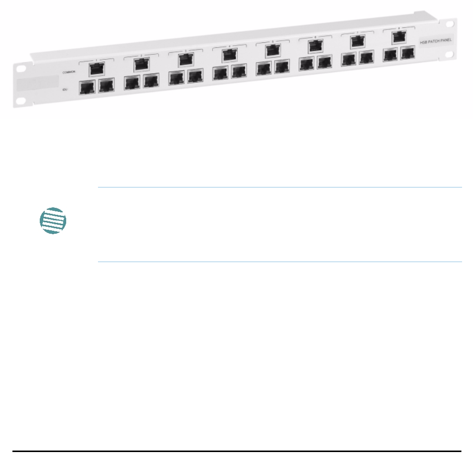
• One Y-Connection Patch Panel
• One MHS cable
Figure 12-2: RADWIN Y-Connection Patch Panel
Installing a RADWIN MHS
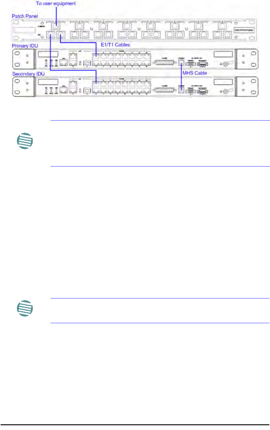
Figure 12-1 above is a schematic of a RADWIN MHS. Figure 12-3 shows how to connect
the IDUs to the Patch Panel.
Note
The following procedure is substantially generic to all RADWIN radio
products. Differences between WinLink 1000 and RADWIN 2000 class
products will be stated explicitly. What you see on your running RADWIN
Manager may differ in some details from the screen captures used to
illustrate this chapter.
Installing a RADWIN MHS Chapter 12
RADWIN 2000 User Manual Release 2.5.40 12-4
Figure 12-3: How to connect the IDUs to the Patch Panel
In what follows, it will be assumed that –
1. We will depart from our usual Site A / Site B conventions. Sites A and B on the primary link
will be Sites 1.2 and 1.4 respectively. The corresponding sites on the secondary link will be
Sites 2.2 and 2.4. The site names reflect their IP addresses. This is a useful convention and
is reflected in the screen captures below.
2. The link will be managed from Site 1.2; Site 1.4 may be a remote site.
3. The links intended as the primary and secondary will be referred to their respective names,
Primary Link and Secondary Link as shown in Figure 12-1 above, despite their having yet
to be installed.
To install a Hot Standby Link:
1. Set up Primary Link in the usual way. Ensure that it is fully operational in accordance
with the relevant instructions in Part 1 of the User Manual.
2. Connect user equipment to Site 1.4.
3. At Site 1.2, disconnect the TDM cables from the external equipment or disconnect
external equipment from the Hot Standby Patch Panel.
4. The HSS cable (connecting the ODUs) should be connected at Site 1.2. The ODU
belonging to the primary link should be configured as HSM, whereas the ODU
belonging to the secondary link should be configured as HSC-CT.
5. Establish Secondary Link in the usual way, with HSS enabled. The two link fre-
quencies should be at least 5MHz apart.
Note
•With RADWIN 2000 links you can protect up to 16 TDM ports. To pro-
tect more than eight TDM ports use two Patch Panels at each site.
• Ethernet services are carried independently by primary and second-
ary links. Each link carries different Ethernet traffic. MHS does not
protect Ethernet traffic.
Note
Do not proceed unless this condition is fully met!

Installing a RADWIN MHS Chapter 12
RADWIN 2000 User Manual Release 2.5.40 12-5
6. Connect the MHS cables at Sites A and B as shown in Figure 12-1 and Figure 12-
3 above.
7. Run the Configuration Wizard for Primary Link. Activate TDM services in the usual
way. Navigate to the Hot Standby tab, in the Services Configuration panel:
Figure 12-4: Services Configuration Panel: Hot Standby mode selection
Check the Primary button to configure Primary Link as the primary link.
8. Complete the Wizard, and then move to Secondary Link.
9. Repeat step 7 for Secondary Link. For the Services Hot Standby tab, this time, check
the Secondary button.
10. Complete the Wizard.
11. At Site 1.2, reconnect the Hot Standby Patch panel to the external equipment.
From this point on, we will simply refer to primary and secondary link (no capitalized names).
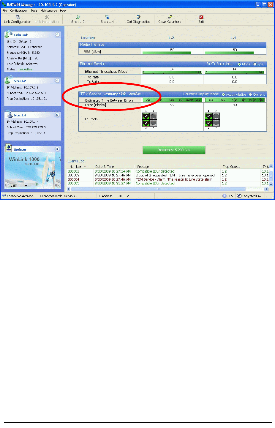
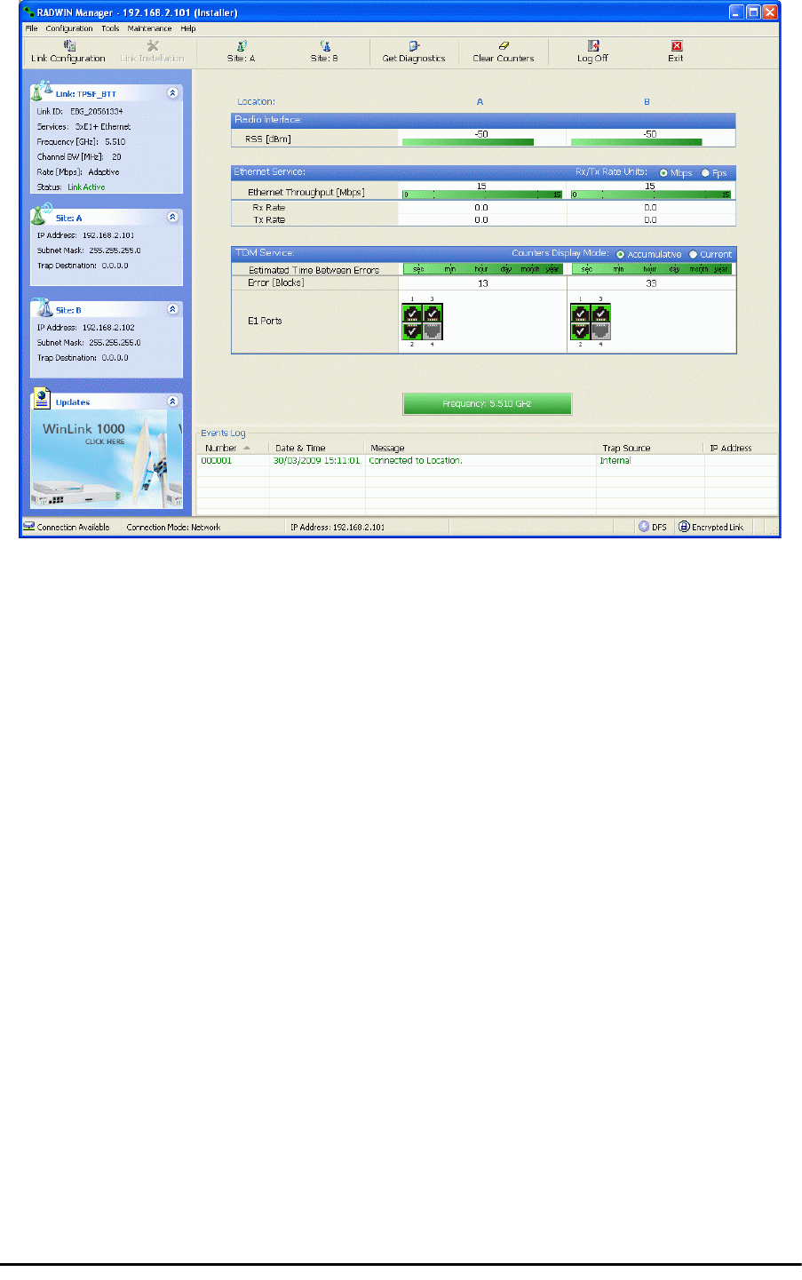
At the end of the process, the RADWIN Manager main windows should look like this:
Installing a RADWIN MHS Chapter 12
RADWIN 2000 User Manual Release 2.5.40 12-6
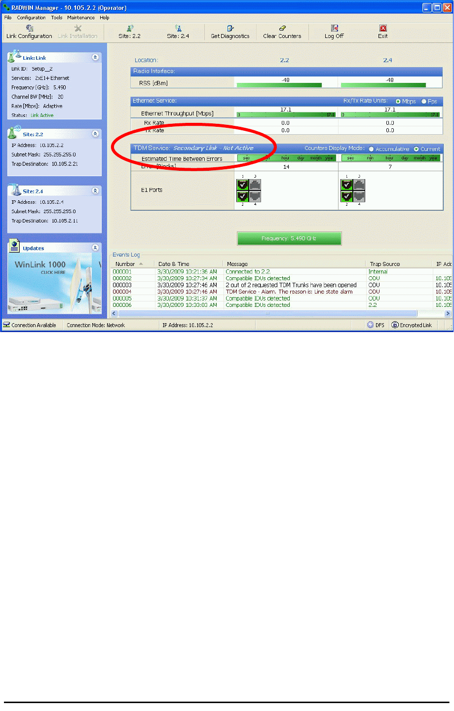
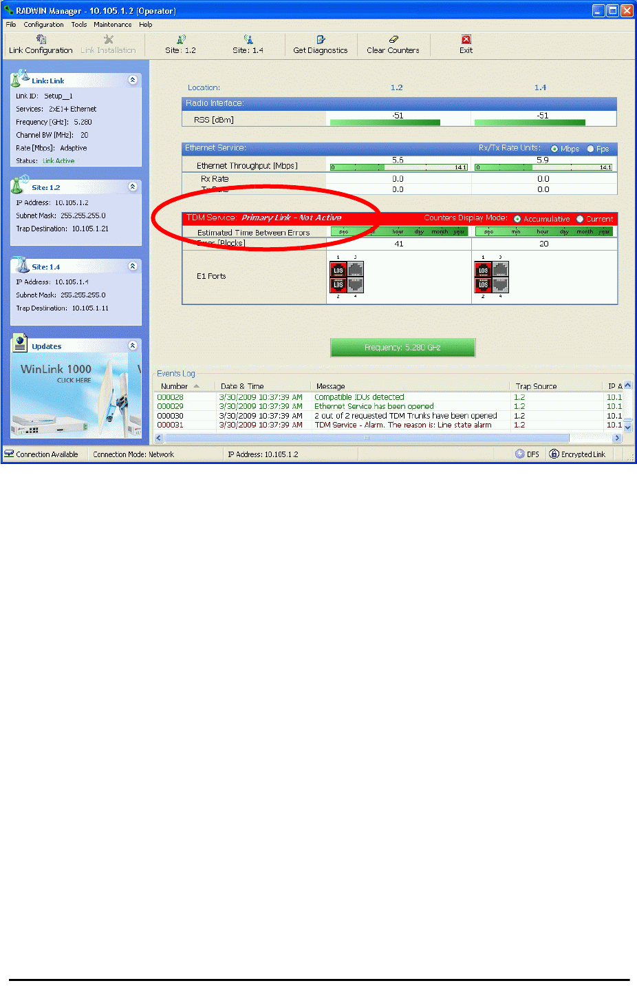
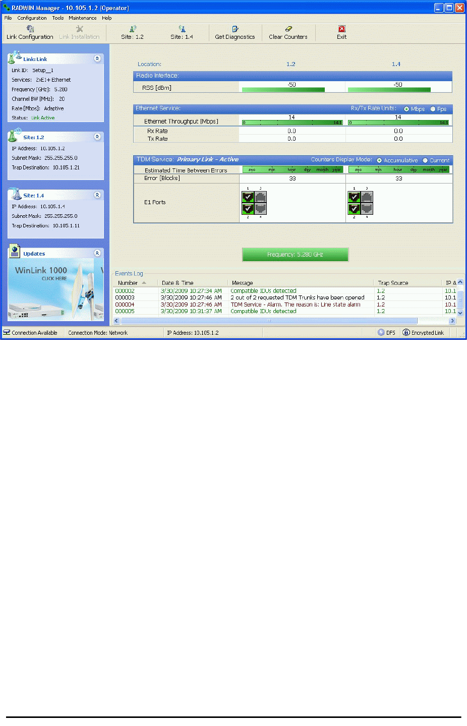
Figure 12-5: The primary link under normal operation
Installing a RADWIN MHS Chapter 12
RADWIN 2000 User Manual Release 2.5.40 12-7
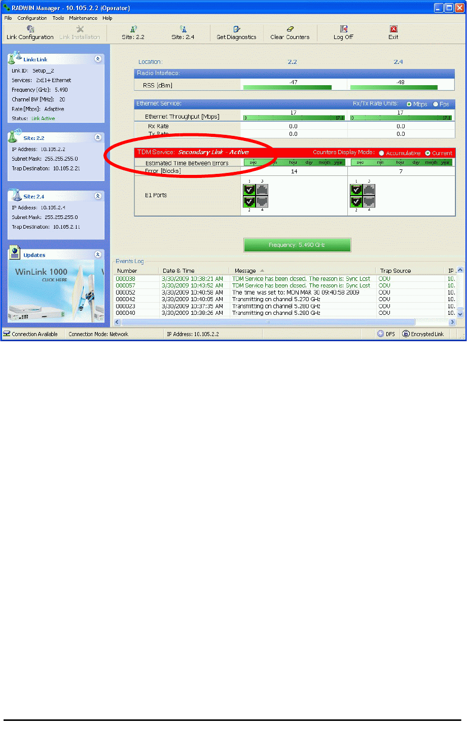
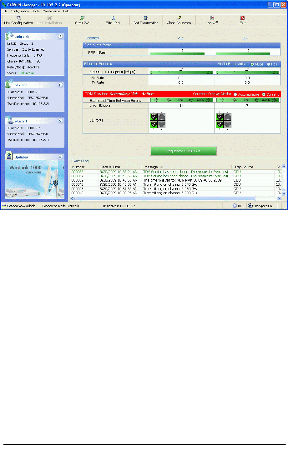
Figure 12-6: The secondary link under normal operation
To see what happens following a cut-over from the primary link to the secondary link, you
need to have running two copies of the RADWIN Manager – one logged into the primary link,
and one logged into the secondary link.
Here then, is the situation after a cut-over to the secondary link:
For the primary link, the following window will appear for a few seconds:
Installing a RADWIN MHS Chapter 12
RADWIN 2000 User Manual Release 2.5.40 12-8
Figure 12-7: Primary link a few seconds before regular No-Link display
It will then revert to the standard No-Link-available window.
On the secondary link Manager window, you will see a window like this:
Maintaining a RADWIN MHS Link Chapter 12
RADWIN 2000 User Manual Release 2.5.40 12-9
Figure 12-8: Secondary Link operating as the Hot Standby link
Notice that the active link notice is highlighted in red, so that there is no mistaking which link
is operational.
Maintaining a RADWIN MHS Link
IDU Replacement
There are two situations, which must be treated differently.
Situation 1:
To replace either of the IDUs at Site 1.4 or the IDU at Site 2.2, nothing special is required.
Simply disconnect the IDU to be replaced – and replace it with a new one. Replacing a sec-
ondary link IDU obviously has no effect on the TDM service. Disconnecting the Site 1.4 pri-
mary IDU activates Hot Standby. After the Site 1.4 primary IDU is replaced, the Link will
detect the change and switch back to the primary link.
If you replaced the Site 2.2 IDU, remember to reconnect the MHS cable.
Situation 2:
Replacing the Site 1.2 IDU is different, and requires several steps.
To replace the Site 1.2 primary link IDU:
1. Power off the Site 1.2 IDU. This activates the secondary link using Hot Standby.

ODU Replacement Chapter 12
RADWIN 2000 User Manual Release 2.5.40 12-10
2. Run the Configuration manager on the secondary link, and in the Hot Standby panel
of Figure 12-4 above, check the Disabled button.
3. Replace the Site 1.2 IDU without connecting it to the ODU (to prevent transmission
by the primary link with the undefined IDU).
4. Reconnect the MHS cable between the IDUs at Site 1.2.
5. Again, run the Configuration Wizard on the secondary link, and in the panel of
Figure 12-4 above, check the Secondary button to re-enable the link as secondary.
6. Connect the new Site 1.2 IDU to its ODU.
The Hot Standby will automatically revert to the primary link within 50ms.
ODU Replacement
Both the primary and secondary replacement ODUs require pre-configuration prior to inser-
tion into the link. The items to be pre-configured are
•HSS mode
•Link ID
•Frequency
• Hot Standby mode – using the new Services panel in Figure 12-4 above
• IP address (optional)
To pre-configure an ODU:
1. Attach the new ODU to an IDU or a PoE device.
2. Run the RADWIN Manager and use Hot Standby tab of Figure 12-4 above to config-
ure the new ODU to Primary or Secondary mode as required.
3. Ensure that it is set to the proper HSS mode in accordance with Figure 12-4 above.
Enter the required Link ID and frequency.
To replace an ODU for primary or secondary link, at either site:
• Install the pre-configured ODU. (Since the other link is working normally, nothing
need be done with it. If the secondary ODU was replaced, TDM service remains as is
on the primary link. If the primary ODU was replaced, then the TDM service will shift
back to the primary link.)
Switching Logic
Switching from Primary Link to Secondary Link
Switching from primary link to secondary link will occur following:
• Loss of the primary air interface due to sync loss
Note
Pre-configuration must be carried out before the new ODU is
connected to its IDU. If you try to do it “live” against its IDU, it will
cause spurious transmissions and a service break.
Switching from Primary Link to Secondary Link Chapter 12
RADWIN 2000 User Manual Release 2.5.40 12-11
• Loss of the primary air interface due to failure of the receiver to acquire expected E1/
T1 data during a period of 24ms
• The Primary equipment (either ODU or IDU, local or remote) is powered off
Following the switch from the primary to the secondary link, the primary and secondary link
Manager main windows should look like this:
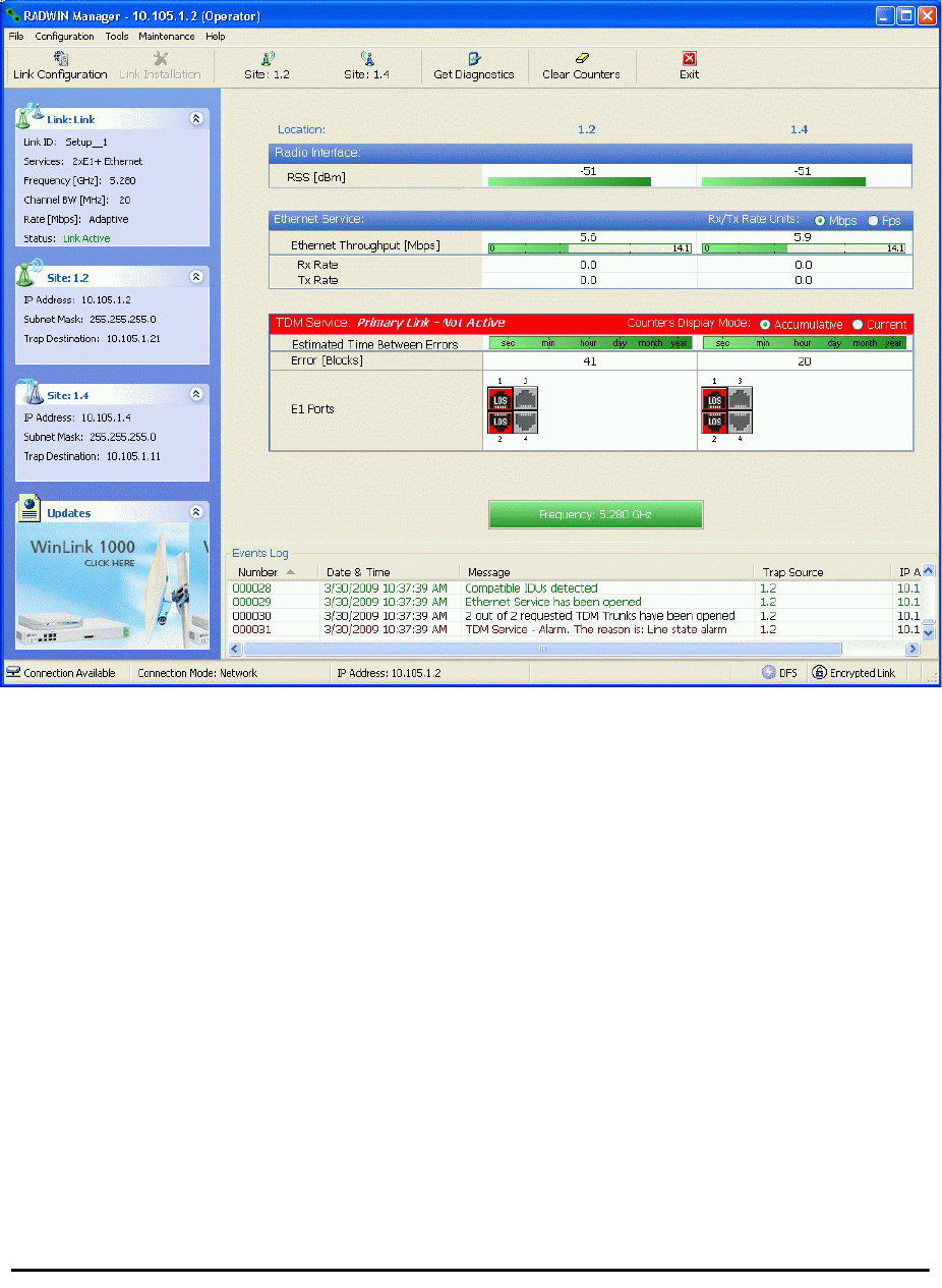
Figure 12-9: Primary link after the switch over to secondary link (After a few seconds the dis-
play moves to No-Link display, with TDM ports grayed out.)
Switching back from the Secondary to the Primary Link Chapter 12
RADWIN 2000 User Manual Release 2.5.40 12-12
Figure 12-10: Secondary link operating after the switch over to secondary. (After a few
moments the TDM icons become green.)
Switching back from the Secondary to the Primary Link
Switching back from the secondary link to the primary link will occur after the primary link has
become and remains fully functional for a continuous period of at least one second. Following
reversion from the secondary link to the primary link, the Manager main windows should look
like this:
Switching back from the Secondary to the Primary Link Chapter 12
RADWIN 2000 User Manual Release 2.5.40 12-13
Figure 12-11: Primary link operating after the switch back from secondary

System Operation description Chapter 12
RADWIN 2000 User Manual Release 2.5.40 12-14
Figure 12-12: Secondary Link operating after the switch back to Primary
System Operation description
Normal operation • TDM services are carried by the primary link
• The secondary link (equipment and air interface) is operating but not carrying user traffic
•TDM ports on the secondary IDUs are tri-state
Switching to backup
• Switching to secondary will occur in the following cases:
• Loss of the primary air interface due to sync loss
• Loss of the primary air interface due to failure of the receiver to acquire expected
TDM data during a period of 24ms
• Primary equipment power off (either ODU or IDU, local or remote)
• The switching result would be:
• TDM ports on the primary IDUs turn to tri-state
• TDM ports on the secondary IDUs become active
Backup operation • TDM services are carried by the secondary link
Switching back to
primary • Switching back to primary will occur as soon as the Primary link is fully functional for 1
second

RADWIN 2000 User Manual Release 2.5.40 13-1
Chapter 13
The RADWIN Ethernet
Ring
Scope
The description of RADWIN Ethernet Ring in this Chapter is completely generic: Both WinLink
1000 and RADWIN 2000 links may participate in an Ethernet ring.
What is an Ethernet Ring
An Ethernet ring consists of several nodes connected by hops (links). Loops are not allowed
with Ethernet; therefore one hop is a Ring Protection Link (RPL) which “blocks” Ethernet
traffic. In the event of failure in the ring, the Ring Protection Link unblocks and Ethernet traf-
fic in the ring is restored.
Some terminology:
•Normal State – all member links are functional except the RPL which is blocked.
•Blocked - the air-link is up but Ethernet traffic is not transmitted across the link. The
Ethernet service panel for the RPL in the RADWIN Manager is labeled Idle
•Unblocked - Ethernet traffic is transmitted across the RPL. The Ethernet service
panel for the RPL in the RADWIN Manager is labeled Active
•Protection State – a member link is broken and the RPL passes Ethernet traffic
•Ring Protection Link - as described above
•Ring Link - any member link controlled by the RPL
•Independent Link - not subject to ring protection
Caution
VLAN IDs are used by RADWIN products in three separate contexts:
Management VLAN, Traffic VLAN and Ethernet Ring. It is recommended that
you use different VLAN IDs for each context.
RADWIN Ethernet Ring Chapter 13
RADWIN 2000 User Manual Release 2.5.40 13-2
•Ring Protection Message (RPM) - control message used to monitor and control the
ring.
RADWIN Ethernet Ring
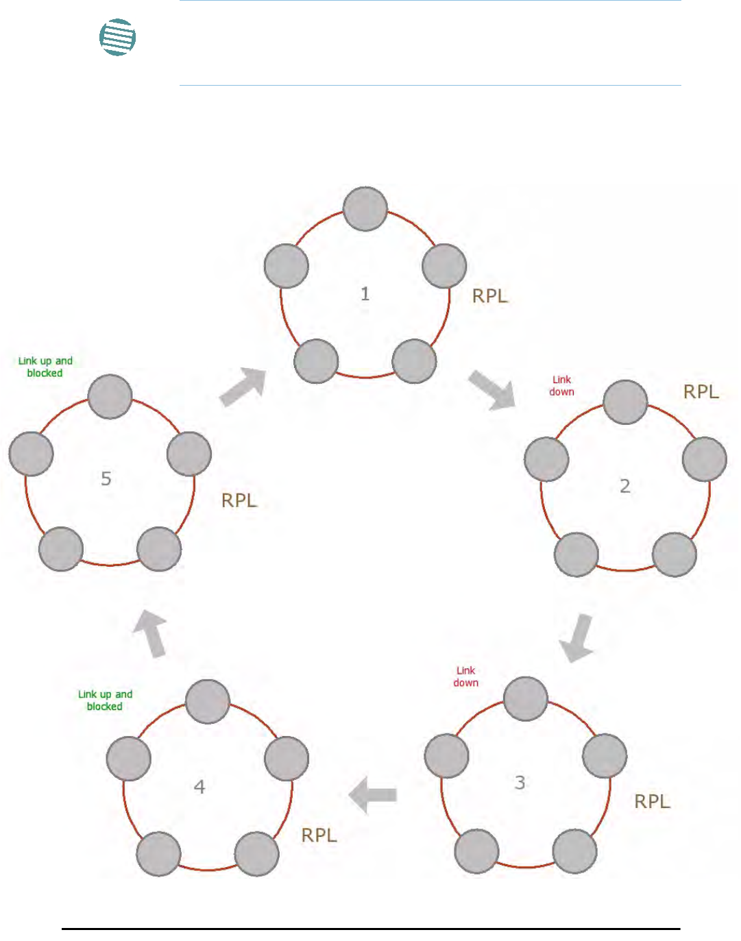
The following figure describes the RPL behavior during a ring failure and recovery cycle.
Figure 13-1: Ring Protection mechanism
Note
RPM messages are broadcast, so it is essential (to prevent flooding) to
associate the RPL and member Ring LInks with a VLAN ID. This requires in
turn, that equipment used in the ring either supports VLAN or can
transparently pass through VLAN tagged packets.

RADWIN Ethernet Ring Chapter 13
RADWIN 2000 User Manual Release 2.5.40 13-3
The steps below follow the numbering in Figure 13-1:
1. Normal operation
Ethernet traffic runs in the ring, but does not pass through the RPL, which is blocked. The
RPL does however, broadcast RPM packets through the ring.
2. Ring Link down, RPL notified
The RPL detects a link-down condition by the non-arrival of an RPM packet. It remains
blocked for the Minimum time for failure detection which is configurable using the
RADWIN Manager (see page 13-9).
3. Ring Link down, RPL unblocked for traffic
The RPL unblocks for Ethernet traffic after the Minimum time for failure detection
expires and no RPM message has been received.
4. Ring Link restored but still blocked for traffic
The Ring Link is restored, but remains blocked for the Minimum time for recovery, set
using the RADWIN Manager, to avoid rapid fluctuations leading to potential short term
loops (see page 13-9).
5. Ring Link restored, RPL blocked for traffic
The RPL blocks to Ethernet traffic after the Minimum time for recovery expires and
restores Ethernet traffic to the Ring Link (with a special RPM packet).
Return to 1.) Ring Link restored, RPL blocked for traffic
The ring is back to normal operation.
With RADWIN links, RADWIN’s Ring Protection solution prevents Ethernet loops in the ring at
all times. The ring is always broken somewhere.
• Under a ring configuration a RADWIN Ring Link that was down and commences recov-
ery, keeps blocking Ethernet traffic. The RPL identifies this situation, blocks itself and
then unblocks the other Ring Link. This is the transition from step 4 to 5 in
Figure 13-1.
• If the failed hop is not a RADWIN link then there are two possibilities:
• If the hop Ring Link can signal that it is down by issuing a Loss of Signal (LOS) at
the Ethernet port, then the RPL will control the RADWIN link connected to that
port in the same manner as described above, to prevent an Ethernet loop.
• Otherwise, there may be a short loop period when the RPL is still open for traffic
and the Ring Link is also unblocked during the Minimum time for recovery.
Ethernet Ring Topologies Supported by RADWIN Chapter 13
RADWIN 2000 User Manual Release 2.5.40 13-4
Ethernet Ring Topologies Supported by RADWIN
The following ring topologies are supported:
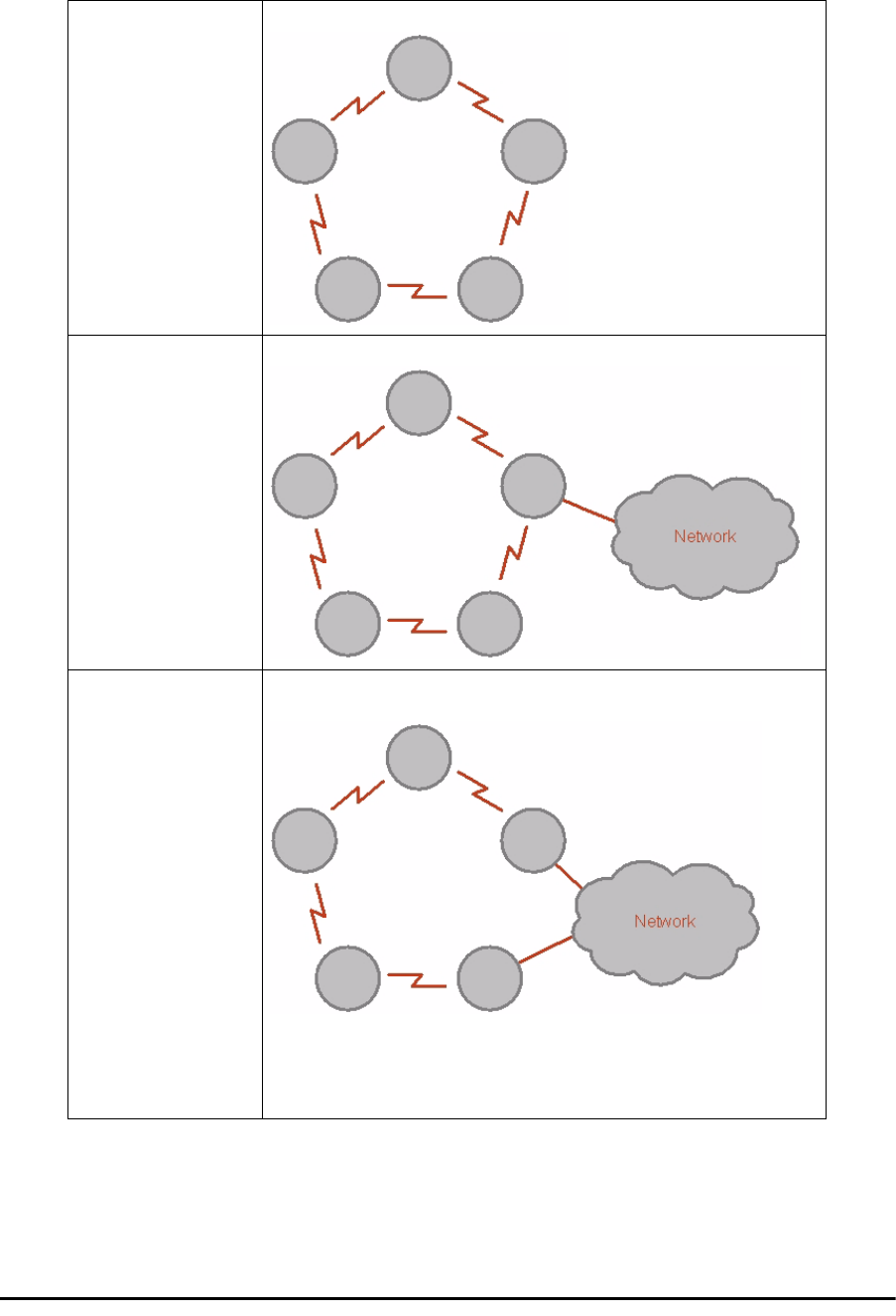
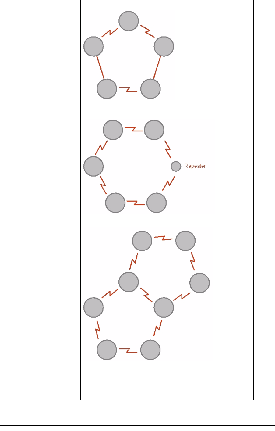
Table 13-1: Topologies supported by RADWIN Ethernet Ring
Stand-alone ring
The ring is not connected to other rings
Single-homed ring
One of the nodes is connected to another network / ring:
Dual-homed ring
Two adjacent nodes are connected through a non-RADWIN link (e.g. micro
wave or fiber):
Note:
• The network has to be layer 2 and support VLANs
• The ring control broadcasts RPM packets. Hence it is recommended to
prevent these packets from propagating into the network
Ethernet Ring Topologies Supported by RADWIN Chapter 13
RADWIN 2000 User Manual Release 2.5.40 13-5
Mixed ring
Some of the hops are connected through non-RADWIN links:
Repeater sites
Some of the hops are connected through RADWIN links with PoE devices, not
supporting ring functionality:
Shared ring
RADWIN rings with shared hops.
Note:
• A RADWIN link hop can be a part of up to 4 rings
• The RPL cannot be a shared link
• The two RPLs should use different Minimum Time for Activation values
to prevent duplicate action causing a loop
Table 13-1: Topologies supported by RADWIN Ethernet Ring (Continued)
Protection Switching Chapter 13
RADWIN 2000 User Manual Release 2.5.40 13-6
Protection Switching
Protection switching occurs upon failure in the ring.
The Ethernet service restoration time depends on the number of hops in the ring. With four
hops the Ethernet service is restored in less than 50 ms.
In single and dual homed topologies the service restoration may take longer due to the aging
time of the external switches. Switches that are immediately aware of routing changes reduce
the restoration time.
Hardware Considerations
Ethernet Ring Protection is supported by the IDU-C, IDU-E and PoE.
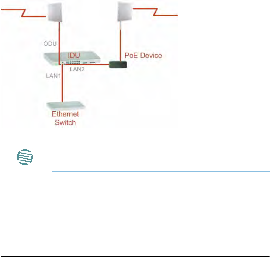
A typical Ring Protection Link consists of an IDU-C or new style IDU-E, a PoE and two ODUs
as shown in Figure 13-2. Hence one end of the RPL and of ring controlled links, as shown in
Figure 13-2 has to be an IDU. It is recommended to have an IDU at each node to have the
flexibility to change the RPL.
A ring node is built from two ODUs from adjacent links. The ODUs can be connected to either
an IDU or to a PoE device as in Figure 13-2. Port names in the IDU are shown.
Figure 13-2: Node with IDU and PoE device
The switching function is carried out by the IDU-Cs and IDU-Es, both of which provide Layer
2 support (see Chapter 14).
Special Case: 1 + 1 Ethernet Redundancy
The same device may be used to provide economic 1 +1 redundancy for a single link.
A 1+1 Ethernet is a ring with two nodes. One of the links is RPL.
Note
Connect the switch at the site only to one IDU.
Using RADWIN Manager to Set up a Ring Chapter 13
RADWIN 2000 User Manual Release 2.5.40 13-7
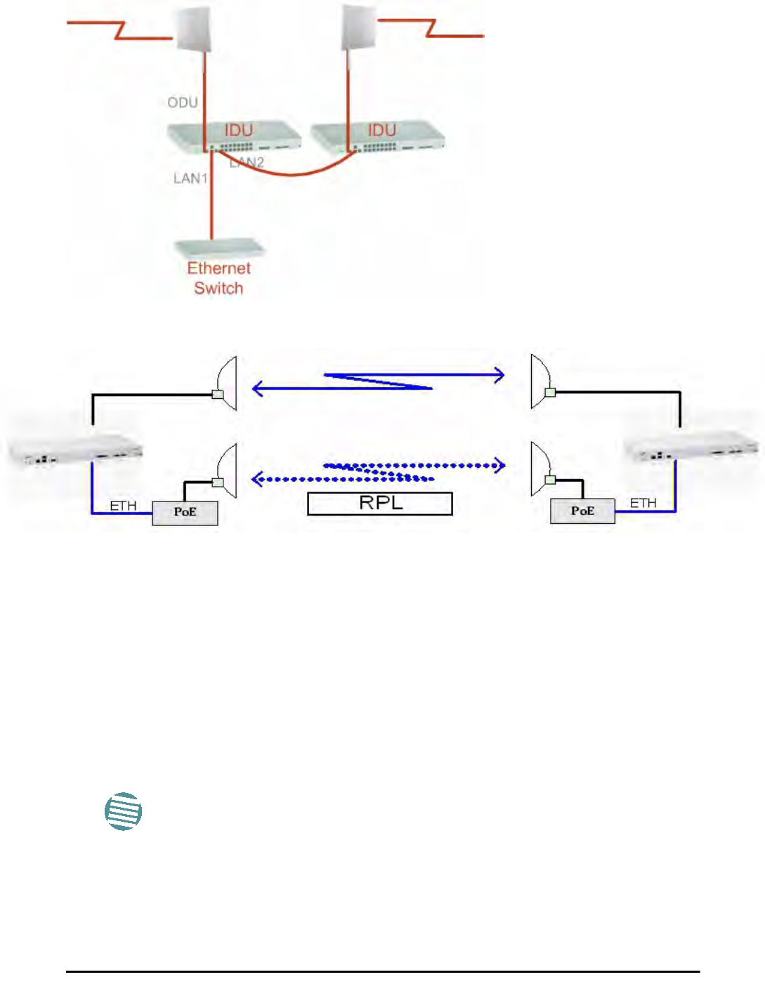
The equipment in a 1+1 Ethernet installation is as follows:
Figure 13-3: 1+1 Ethernet
Figure 13-4: Using IDU-C or IDU-E with PoEs for the RPL
Notice that link content drops from four PoEs plus two switches to two PoEs and two IDU-Cs
or IDU-Es.
Using RADWIN Manager to Set up a Ring
Creating a Ring using RADWIN Manager requires two stages:
6. Set up each participating link separately, in the usual way
7. For each link, run the Configuration wizard to define it as RPL or a Ring Link
Here then, is step 2 in more detail:
Note
• The Ring uses a VLAN ID for the RPL. It is used to manage the Ring
and nothing else; it is completely separate from the management
and traffic VLANs referred to elsewhere
• A regular Ring Link may be a member of up to four rings and each of
their RPL VLAN IDs must be configured
Using RADWIN Manager to Set up a Ring Chapter 13
RADWIN 2000 User Manual Release 2.5.40 13-8
To integrate a link into an Ethernet Ring:
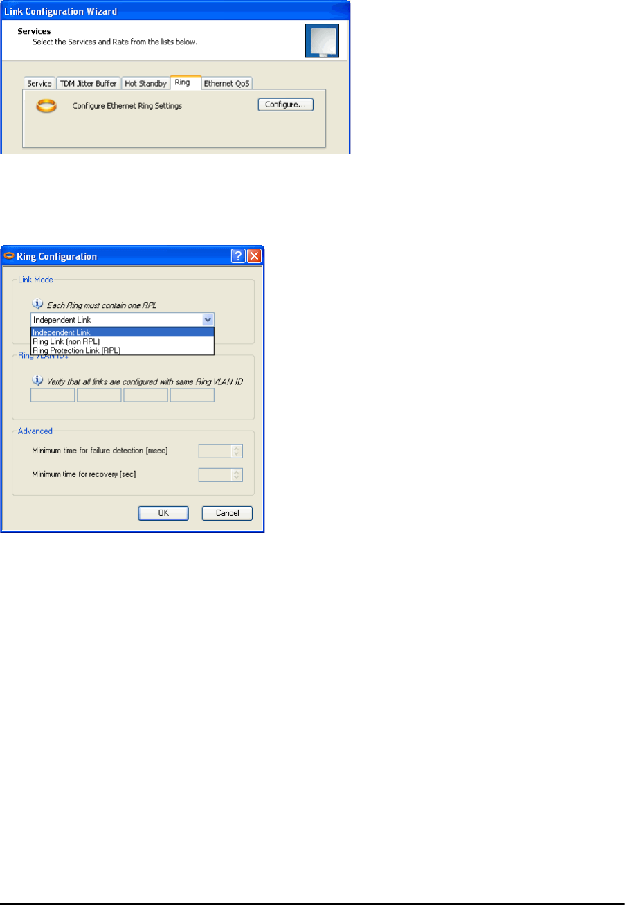
1. Using either the Installation or Configuration wizards, navigate to the Services win-
dow and chose the Ring tab.
Figure 13-5: Services window with Ring selected
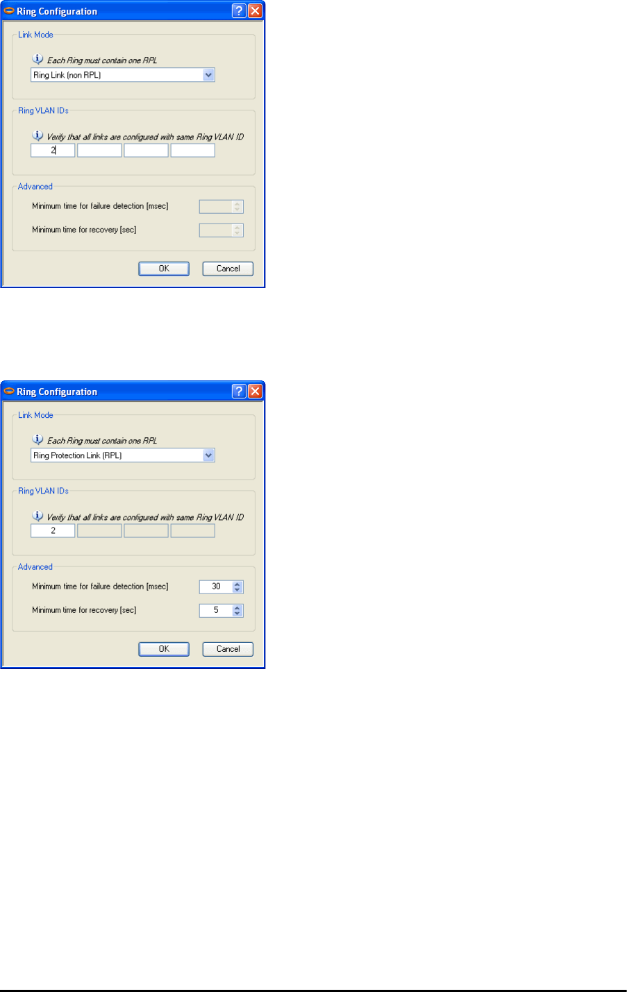
2. Click Configure. The Ring definition window is displayed. The default is Indepen-
dent Link and is used when the link is not part of any Ring.
Figure 13-6: Ring Options
3. To configure the link as a regular Rink link, click Rink Link (Non- RPL) and enter
the ring LAN VIDs (at least one) to which it belongs and click OK:
Using RADWIN Manager to Set up a Ring Chapter 13
RADWIN 2000 User Manual Release 2.5.40 13-9
Figure 13-7: Configuring Ring LAN VIDs
4. To configure the link as RPL, click Ring Protection Link (RPL) and enter its Ring
VID.
Figure 13-8: Configuring RPL VIDs
5. Enter the minimum times for failure detection and recovery.
For dual-homed configurations, where part of the ring goes through the core, if a
core segment fails, the core should be allowed to recover before the RPL enters Pro-
tection State. Otherwise, it could happen that both the core and the RADWIN ring
will switch in parallel. You should therefore, configure a Minimum time for failure
detection high enough to take this possibility into account.
The Minimum time for recovery is a delay switch to prevent rapid “on-off” fluctu-
ations. It functions like a delay switch use to protect electrical devices from rapid
“on-off” power fluctuations, which in this context, may lead to potential short term
loops.
6. Click OK to accept your settings.
Using RADWIN Manager to Set up a Ring Chapter 13
RADWIN 2000 User Manual Release 2.5.40 13-10
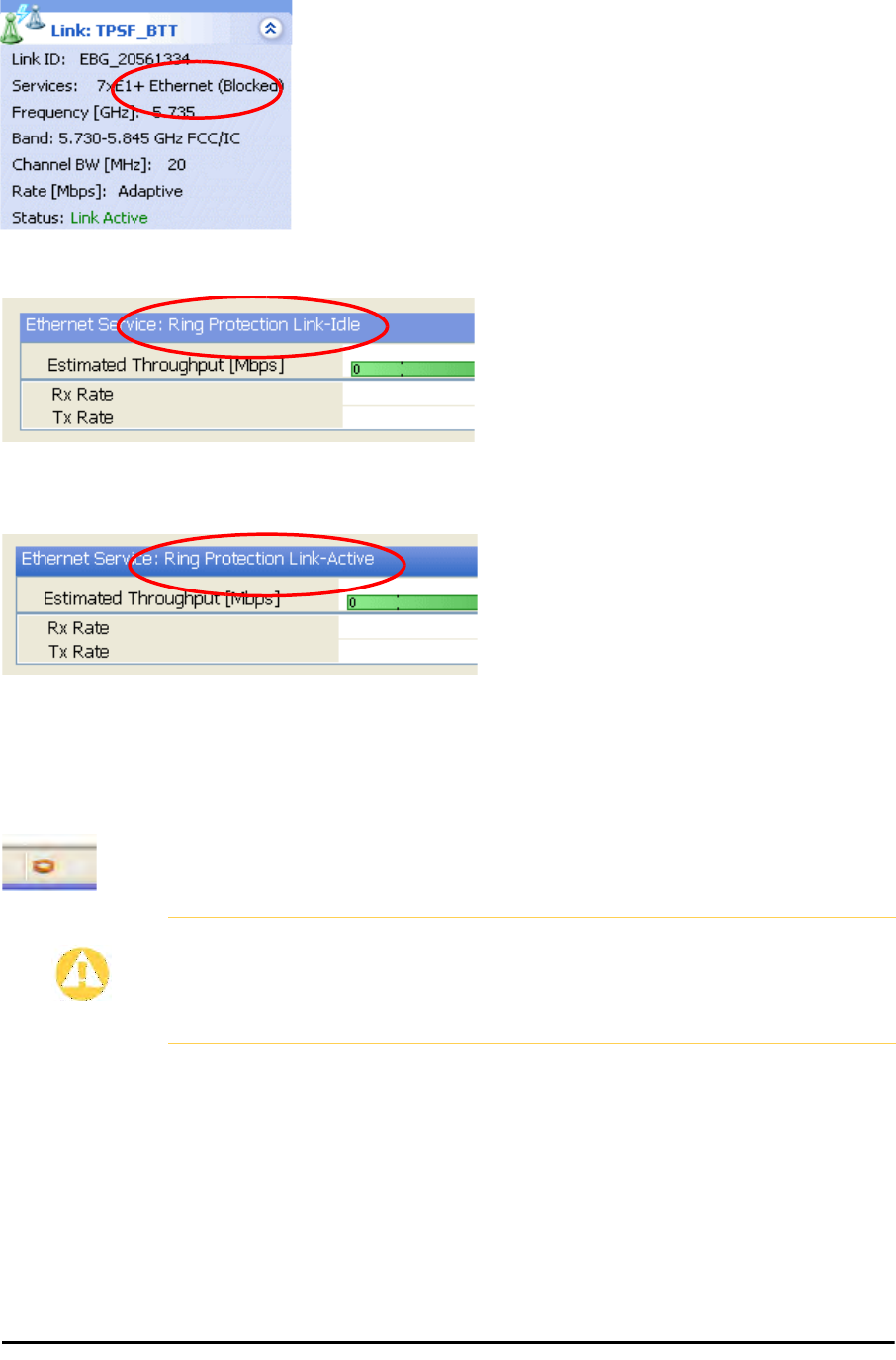
The RPL will be clearly indicated in the RADWIN Manager. In the Link status area on
the top left, you will see an Ethernet (Blocked) notice:
A Link-Idle message is displayed on the Ethernet Services Bar:
When the RPL cuts in as a result of a failure, the “Ethernet (Blocked)” notice disap-
pears. The Ethernet Services Bar indicated that the RPL is active:
Upon restoration of the broken link, the RPL returns to idle status with the appropri-
ate indications on the RADWIN Manager main window.
On the status bar for all ring member links, you will see the ring membership indica-
tor icon:
Caution
• Do not configure more than one RPL. If you do, you will break the
Ring
• If you forget to configure one RPL in a Ring, you will introduce a loop
into your network
RADWIN 2000 User Manual Release 2.5.40 14-1
Chapter 14
VLAN Functionality with
RADWIN 2000
VLAN Tagging - Overview
VLAN Terminology
Both the technical literature and the RADWIN Manager use the terms VLAN ID and VID inter-
changeably to denote a VLAN identification number.
VLAN Background Information on the WEB
The standards defining VLAN Tagging are IEEE_802.1Q and extensions.
For general background about VLAN see http://en.wikipedia.org/wiki/Virtual_LAN.
Background information about Double Tagging also known as QinQ may be found here:
http://en.wikipedia.org/wiki/802.1QinQ.
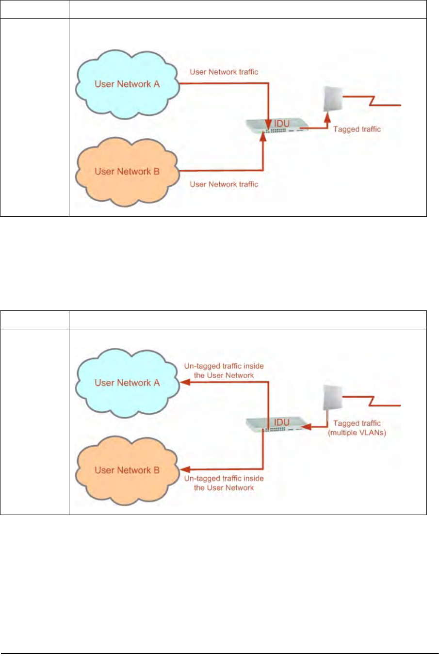
VLAN Tagging
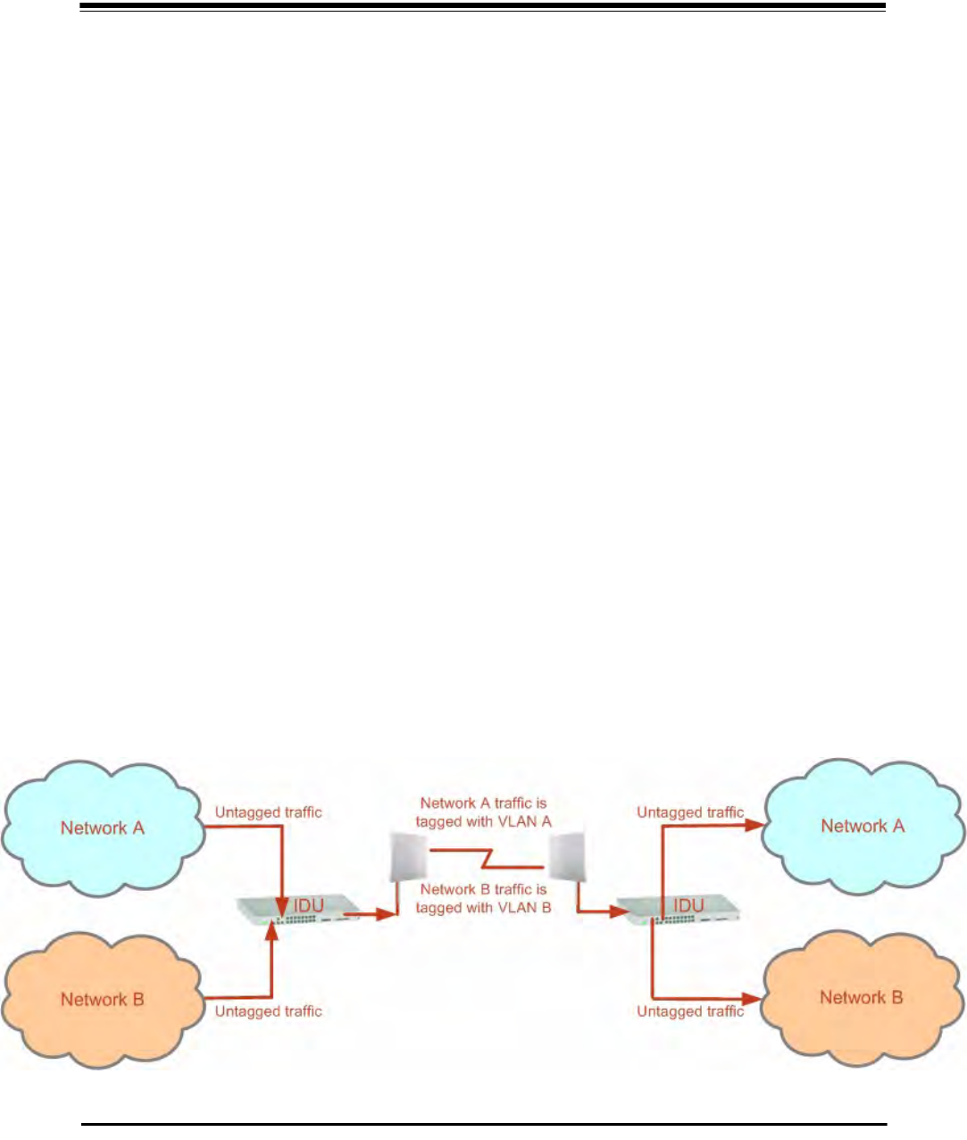
VLAN tagging enables multiple bridged networks to transparently share the same physical
network link without leakage of information between networks:
Figure 14-1: Two network using the same link with tagging
QinQ (Double Tagging) for Service Providers Chapter 14
RADWIN 2000 User Manual Release 2.5.40 14-2
IEEE 802.1Q is used as the encapsulation protocol to implement this mechanism over Ether-
net networks.
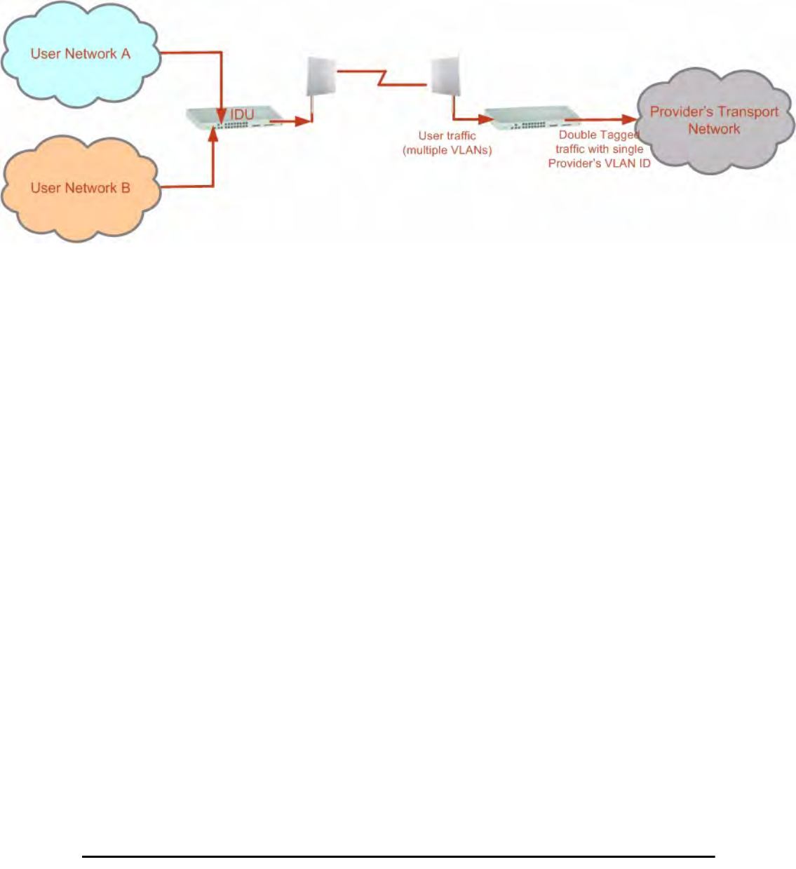
QinQ (Double Tagging) for Service Providers
QinQ is useful for Service Providers, allowing them to use VLANs internally in their “transport
network” while mixing Ethernet traffic from clients that are already VLAN-tagged.
Figure 14-2: Separating client data streams using double tagging
The outer tag (representing the Provider VLAN) comes first, followed by the inner tag. In
QinQ the EtherType = 0x9100. VLAN tags may be stacked three or more deep.
When using this type of “Provider Tagging” you should keep the following in mind:
• Under Provider Tagging, the system double-tags egress frames towards the Provider’s
network. The system adds a tag with a VLAN ID and EtherType = 0x9100 to all
frames, as configured by the service provider (Provider VLAN ID).
• The system always adds to each frame, tags with VLAN ID and EtherType = 0x9100.
Therefore,
• For a frame without a tag – the system will add a tag with VLAN ID and
EtherType = 0x9100 so the frame will have one tag
• For a frame with a VLAN tag – the system will add a tag with VLAN ID and
EtherType = 0x9100 so the frame will be double-tagged
• For a frame with a VLAN tag and a provider tag – the system will add a tag with
VLAN ID and EtherType = 0x9100 so the frame will be triple-tagged and so on
VLAN Untagging
VLAN Untagging means the removal of a VLAN or a Provider tag.
Port Functionality
The VLAN functionality is supported by all LAN and SFP ports in the IDU.
Each port can be configured how to handle Ethernet frames at the ingress direction (where
frames enter the IDU) and at the egress direction (where frame exit the IDU).
The configuration is independent at each port.
Port Functionality Chapter 14
RADWIN 2000 User Manual Release 2.5.40 14-3
Ingress Direction
Egress Direction
Table 14-1: Port settings - Ingress direction
Transparent The port ‘does nothing’ with regard to VLANs - inbound frames are left untouched.
Tag
Frames entering the port without VLAN or QinQ tagging are tagged with VLAN ID and Prioritya, which
are pre-configured by the user. Frames which are already tagged at ingress are not modified.
a. Priority Code Point (PCP) which refers to the IEEE 802.1p priority. It indicates the frame priority
level from 0 (lowest) to 7 (highest), which can be used to prioritize different classes of traffic
(voice, video, data, etc).
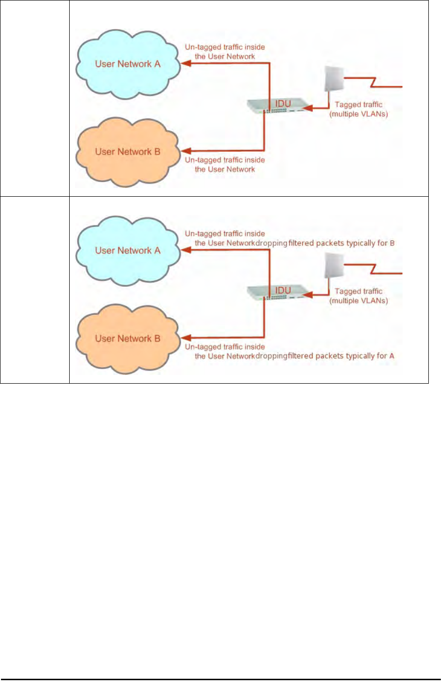
Table 14-2: Port settings - Egress direction
Transparent The port ‘does nothing’ with regard to VLANs - outbound frames are left untouched.
Untag all
All frames are untagged.
Port Functionality Chapter 14
RADWIN 2000 User Manual Release 2.5.40 14-4
Untag selected
VIDs
Untags only frames tagged with one of the user defined VIDs. You can define up to eight VIDs per
port. Other frames are not modified.
Filtered VLAN
IDs at egress
This setting allows for mutual filtering of multiple ingress tags not relevant at the egress end:
Table 14-2: Port settings - Egress direction (Continued)
VLAN Availability Chapter 14
RADWIN 2000 User Manual Release 2.5.40 14-5
VLAN Availability
VLAN is available for links using either WinLink 1000 or RADWIN 2000 radios. VLAN support
requires the use of IDU-Cs or new style IDU-Es.
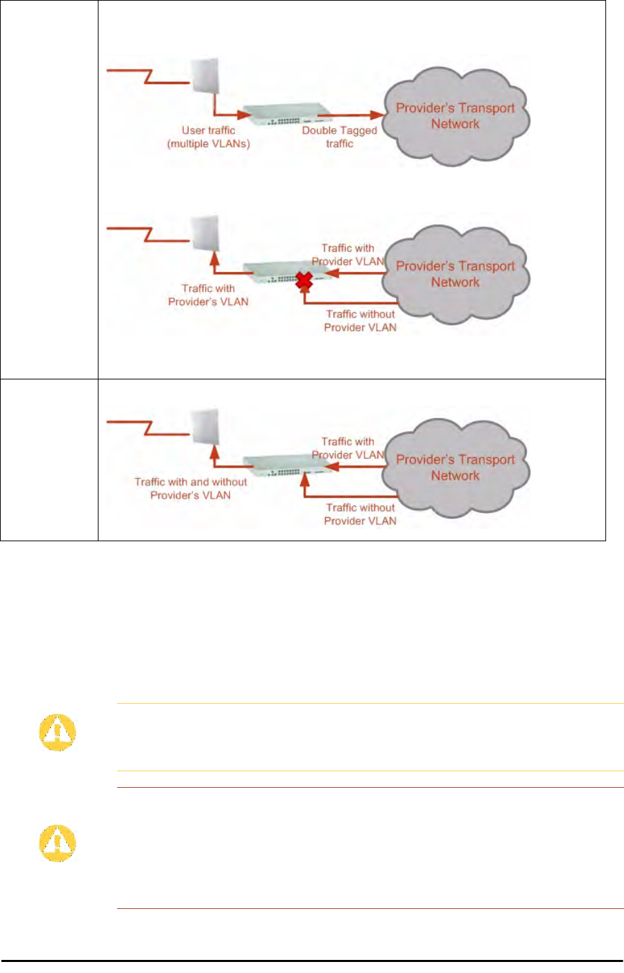
VLAN Configuration Using the RADWIN Manager
Provider
tagging
With Provider tagging, the system double-tags egress frames towards the provider’s network. All
frames are tagged QinQ with a VLAN ID, which is configured by the service provider (Provider VLAN
ID).
With this setting, ingress frames which are not tagged with the configured Provider VLAN ID are
blocked (filtered).
Note: Each port can be configured independently to a tagging mode. However, only a single Provider
VLAN ID can be defined per IDU.
Provider
tagging without
filter
This setting functions like Provider tagging. However, all ingress frames are passed through.
Caution
VLAN IDs are used by RADWIN products in three separate contexts:
Management VLAN, Traffic VLAN and Ethernet Ring. It is recommended that
you use different VLAN IDs for each context.
Disclaimer
If you are not a VLAN expert, please be aware that incorrect VLAN
configuration may cause havoc on your network. The facilities described
below are offered as a service to enable you to get best value from your
RADWIN 2000 links and are provided “as is”. Under no circumstances does
RADWIN accept responsibility for network system or financial damages
arising from incorrect use of these VLAN facilities.
Table 14-2: Port settings - Egress direction (Continued)

Management Traffic and Ethernet Service Separation Chapter 14
RADWIN 2000 User Manual Release 2.5.40 14-6
Management Traffic and Ethernet Service Separation
You can define a VLAN ID for management traffic separation. You should configure the sys-
tem to prevent conflicts as detailed below.
When configured for the default operational mode, a “Provider port” will handle ingress traffic
as follows:
• Filters frames that are not tagged with the Provider VLAN ID
• Removes the Provider double tag
Therefore, if a port is configured for management traffic separation by VLAN and as ‘Provider
port’, then the received management frames must be double tagged as follows:
• The outer tag has to be the Provider’s tag (so the frame is not filtered)
• The internal tag has to be management VLAN ID
To avoid mix-ups, best practice is to:
• Separate the management and data ports
• Define only a data port with Provider function
All IDU-C and new style IDU-E models have two LAN ports so you can easily separate man-
agement and Ethernet service.
VLAN Tagging for Ethernet Service: Configuration
VLAN Configuration is carried out per site. It is up to you to ensure consistency between the
link sites. The discussion below is based on Site A however, it also applies to Site B.
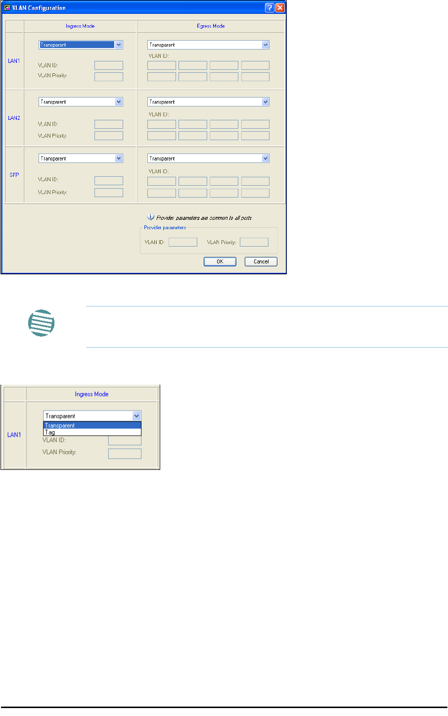
To set up VLAN tagging for Ethernet service, enter Site Configuration for Site A, choose the
Ethernet tab and click the VLAN Configuration... button (Figure 8-15). The following win-
dow is displayed:
VLAN Tagging for Ethernet Service: Configuration Chapter 14
RADWIN 2000 User Manual Release 2.5.40 14-7
Figure 14-3: VLAN tag settings
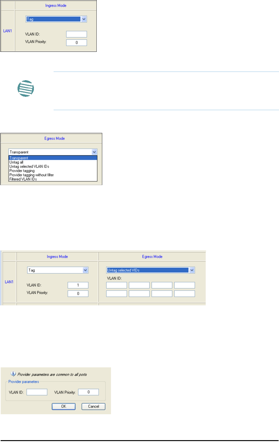
The choices for Ingress Mode are -
Figure 14-4: VLAN: Ingress modes
The two choices correspond respectively to the two rows of Table 14-1. Choosing Tag
causes the VLAN ID and VLAN Priority fields to become available:
Note
If you are using a new style IDU-E, the SFP row will not appear.
VLAN Tagging for Ethernet Service: Configuration Chapter 14
RADWIN 2000 User Manual Release 2.5.40 14-8
Figure 14-5: VLAN: Ingress mode - setting VLAN ID and Priority
The choices for Egress Mode are -
Figure 14-6: VLAN: Egress modes
The five non-transparent choices correspond respectively to the five rows of Table 14-2 in
the order, row 1, 2, 4, 5, 3.
The first two choices, Transparent and Untag all require no further action.
Untag selected VIDs causes the eight VLAN ID fields to become available:
Figure 14-7: Untagging selected VIDs
You may nominate up to eight VIDs for untagging; beyond simple range checking, there is no
other validation.
Both Provider tagging and Provider tagging without filter enable the Provider
parameters fields:
Figure 14-8: Provider parameters
Note
Throughout this chapter, all VLAN IDs must be between 1 and 4094,
inclusive. All VLAN priorities must be between 0 and 6, inclusive. The values
entered are range-checked. If for example, you enter a VLAN ID of 4095,
then 4094 will be reflected back.

VLAN Tagging for Ethernet Service: Configuration Chapter 14
RADWIN 2000 User Manual Release 2.5.40 14-9
There is of course only one Provider VLAN ID. It is most likely yours, as the Provider!
Filtered VLAN IDs enables you to filter and block only frames tagged with one of the user
defined VIDs. You can define up to eight VIDs per port. Other frames are not modified and
are forwarded transparently.
When you are finished, remember to click OK (Figure 14-3) to save your entries.

RADWIN 2000 User Manual Release 2.5.40 15-1
Chapter 15
Software Upgrade
What is the Software Upgrade Utility?
The RADWIN Manager provides a Software Upgrade Utility (SWU) to upgrade the software
(firmware) of installed ODUs in a network. The update files may be located anywhere acces-
sible by the operator.
The SWU provides for:
• Prior backup of the current files prior to upgrade
• Upgrade from a list
• Delayed upgrade
• Various ODU reset options
The default location of the software files is in the installation area, and can be used to restore
factory defaults.
Upgrading an Installed Link
To upgrade software for a link:
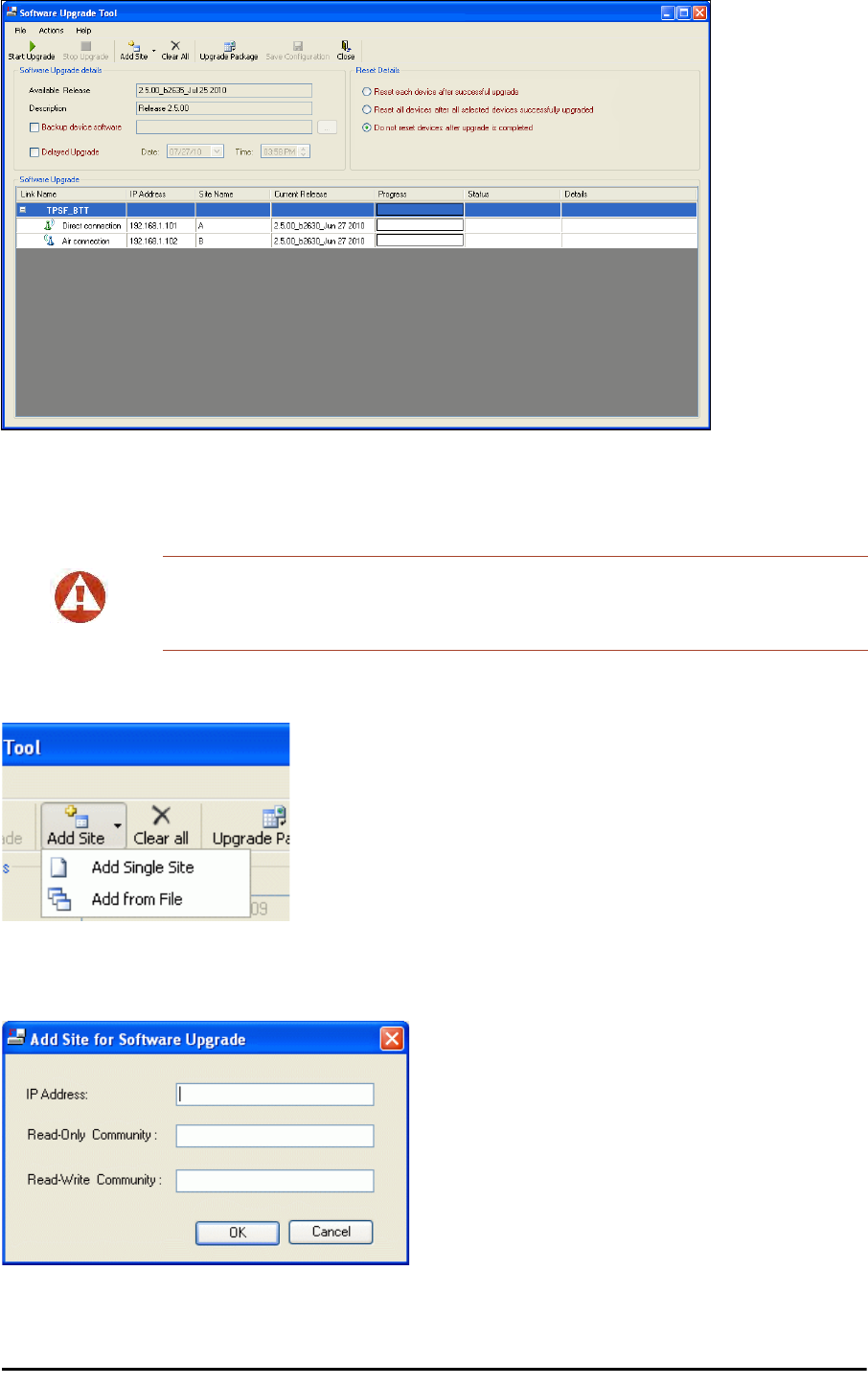
1. In the RADWIN Manager main menu, click Tools | Software Upgrade ... The fol-
lowing detached window appears
Note
The following procedure is generic to all RADWIN radio and GSU products.
Upgrading an Installed Link Chapter 15
RADWIN 2000 User Manual Release 2.5.40 15-2
Figure 15-1: Software Upgrade Utility - Main window
The default sites shown in the Software Upgrade list panel belong to the currently
link. The list may be empty if you are running the RADWIN Manager “offline”.
2. Click Add Site to add additional sites for upgrade.
Figure 15-2: Add site options
Click Add Single Site for one site only:
Figure 15-3: Adding a single site for upgrade
Warning
What follows about adding sites manually or from a list file, assumes that all
sites to be upgraded are of the same type - either WinLink 1000 or RADWIN
2000. but not both. This will not work with a mixed list.
Upgrading an Installed Link Chapter 15
RADWIN 2000 User Manual Release 2.5.40 15-3
Enter the IP address of the site, the Community strings (Default:
public
and
net-
man
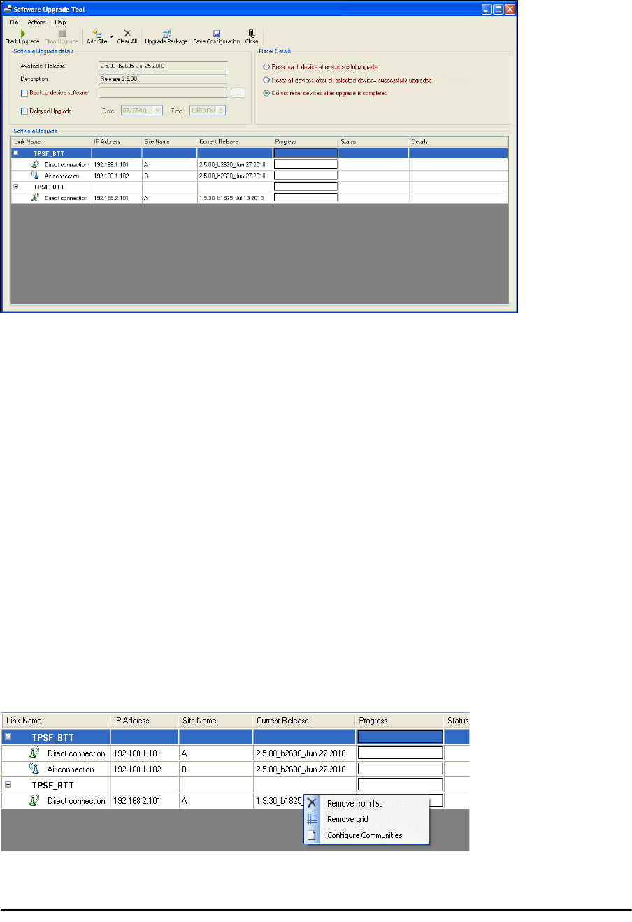
, respectively) and then click OK. The site will appear in the Software Upgrade
list box. For example if we add the site at IP address 192.168.2.101, the SWU main
window of Figure 15-1 looks like this:
Figure 15-4: Single site added for upgrade
The list can be cleared using the Clear All button.
As an alternative to adding sites one at a time, you can add sites from a prepared list
using the Add from File option in Figure 15-2. The list has the following format:
<IP address>,<Read-Only community>,<Read-Write community>
Here is an example:
192.168.1.101,public,netman
192.168.1.102,public,netman
192.168.2.101,public,netman
192.168.2.102,public,netman
3. Having created an update list, click Upgrade Package to chose the relevant files.
The default files are located in the SWU subdirectory in the RADWIN Manager instal-
lation area. They are currently named SWU_1k.swu and SWU_2k.swu. You may
have to find them elsewhere, depending on your system.
4. You make limited changes to the list by right-clicking any line:
Figure 15-5: Software Upgrade site options
Upgrading an Installed Link Chapter 15
RADWIN 2000 User Manual Release 2.5.40 15-4
5. To back up your existing system, check Backup device software check-box. Then
click the button for a standard file dialog. The default location is the My Docu-
ments directory on the managing computer or the last backup directory you used.
6. In addition to the previous step, you may opt to perform a delayed upgrade. Check
the Delayed Upgrade box, and enter the date and time for the delayed upgrade.
7. The radio buttons on the right determines how your sites should be reset. Bear in
mind that on the one hand, a reset involves a service interruption, but on the other
hand, the software upgrade will not become effective until after the reset is carried
out.
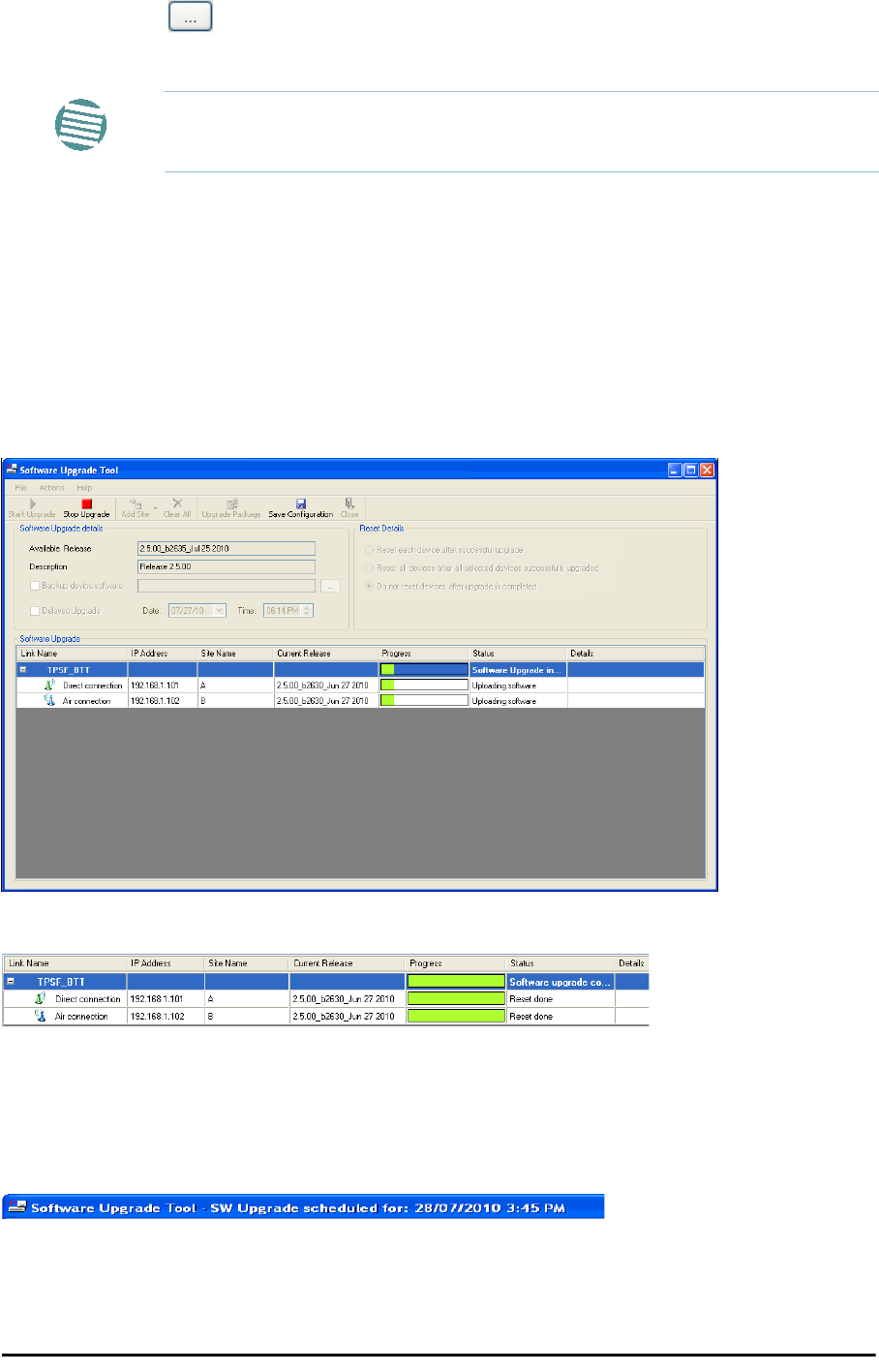
8. Click Start Upgrade to commence the process. For an immediate upgrade you will
be able to observe the upgrade progress from the green progress bars:
Figure 15-6: Software upgrade in progress - Note the stop button
Figure 15-7: Software upgrade completed successfully
9. Click Close to exit.
10. If you requested a delayed upgrade, a notice like this will appear in the SWU title
bar:
Note
The backup here is the same as that in page 8-32, and serves the same
purpose. It provides a fallback if the upgrade proves problematic.

Software Update for GSUs Chapter 15
RADWIN 2000 User Manual Release 2.5.40 15-5
Software Update for GSUs
All GSUs in a distributed site can be updated simultaneously. Use an IP list as described
above.
Caution
If one or both sites fail to update, a warning notice will be displayed.
If one site of a link updates but the other fails, you should correct the
problem and update the second site as soon as possible. If you do not,
following the next reset of the updated site, you could experience a link
software mismatch which may affect service. See page 9-3 for details.

RADWIN 2000 User Manual Release 2.5.40 16-1
Chapter 16
FCC/IC DFS Installation
Procedure
FCC/IC 5.4/5.3 GHz Links: Background
The FCC/IC regulation for 5.4/5.3 GHz allows unlicensed wireless data equipment, provided
that it does not interrupt radar services. If radar activity is detected, the equipment must
automatically change frequency channel. This feature is termed Dynamic Frequency Selection
(DFS). According to the standard, a channel with active radar is prohibited from use for 30
minutes. Before using a channel for transmission, the radio equipment must probe it for radar
signals for a period of 60 seconds.
RADWIN radio products support DFS as well as ACS.
An immediate consequence of the FCC/IC regulation for 5.4/5.3 GHz is that the standard
method of link installation using a single default fixed installation channel, cannot be used.
Instead of the installation procedure of Chapter 5, a link activation method is used.
The ODUs are either supplied from the factory ready for use at 5.4 GHz or 5.3 GHz FCC/IC or
alternatively, they can be set up for these bands using the RADWIN Manager.
FCC/IC 5.4/5.3 GHz Link Activation
To Activate a FCC/IC 5.4/5.3 GHz Link:
1. Install RADWIN Manager software as usual.
2. Connect the PC to the IDU-ODU pair to be used as the local site.
3. Run the RADWIN Manager and log in as Installer. You will see the following window:
Note
The following procedure is generic to all relevant RADWIN radio products.
What you see on your running RADWIN Manager may differ in some details
from the screen captures used to illustrate this chapter.
FCC/IC 5.4/5.3 GHz Link Activation Chapter 16
RADWIN 2000 User Manual Release 2.5.40 16-2
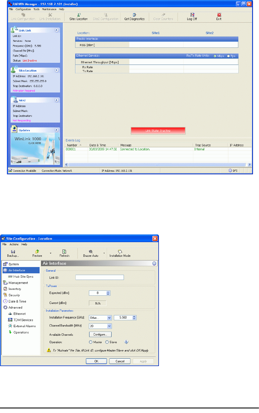
Figure 16-1: Activating an ODU - Inactive link
When the Manager Main Screen is displayed it appears with the Link Status label red
and showing Inactive.
4. Click Site:Location | Air Interface for the logged in site.
5. The Air Interface dialog box opens:
Figure 16-2: Air Interface dialog box
6. Enter the Link ID and note it for use with the second site of the link.
7. Check the Master radio button.
FCC/IC 5.4/5.3 GHz Link Activation Chapter 16
RADWIN 2000 User Manual Release 2.5.40 16-3
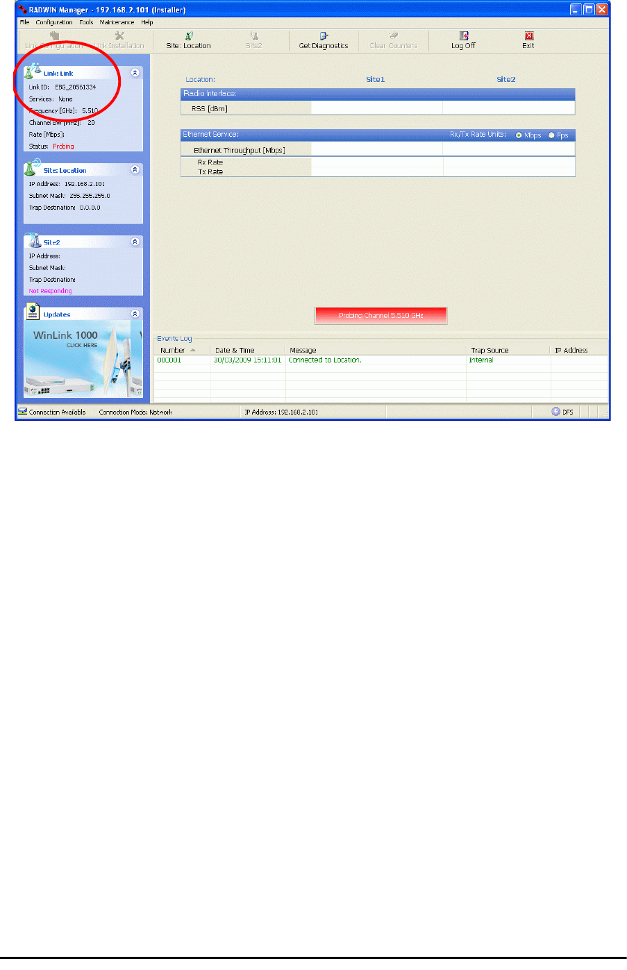
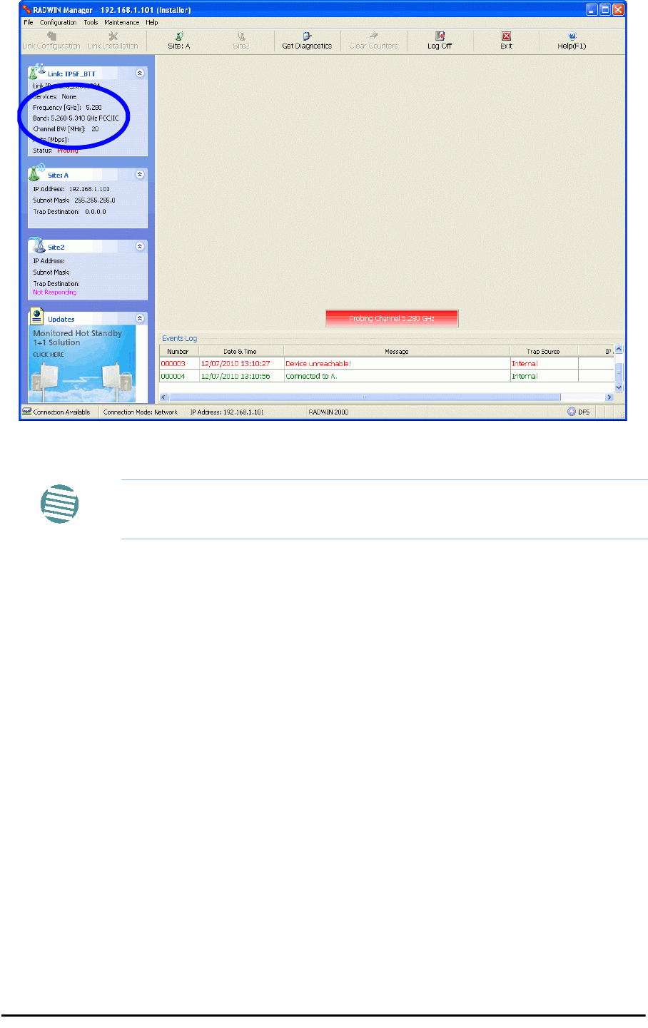
8. Click OK. The following window appears:
Figure 16-3: The local ODU after activation - Probing
Notice that the Link ID is shown in the Link details pane (circled).
9. Repeat the above procedure for the remote ODU, ensuring that in the Air Interface
window, that you enter exactly the same Link ID, but this time that you check the
Slave radio button.
If both ODUs are powered up, after a minute or so a link will be established. If you
are still connected to the remote site (from the previous steps), the window of
Figure 16-3 will look like this:
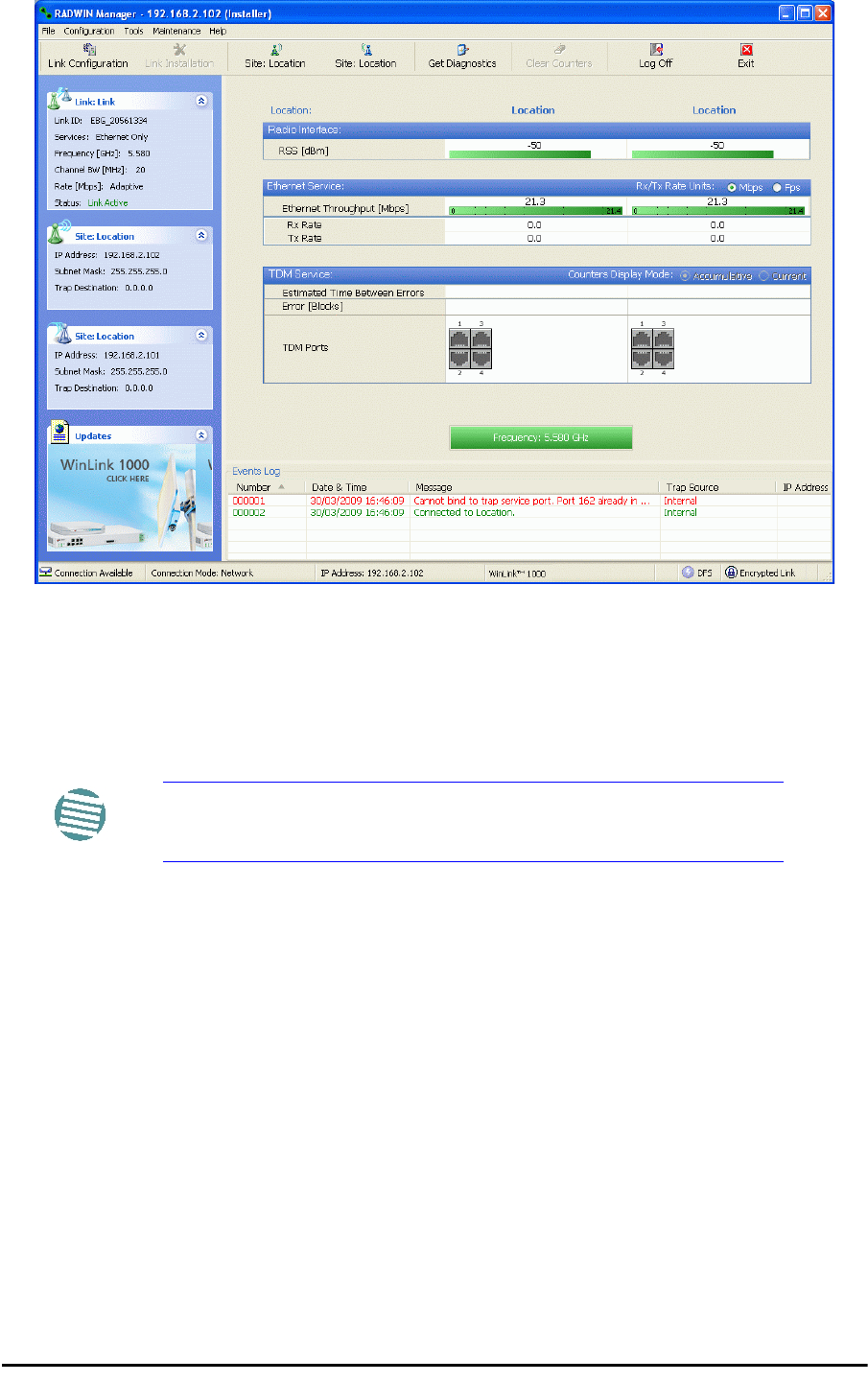
FCC/IC 5.4/5.3 GHz Link Configuration Chapter 16
RADWIN 2000 User Manual Release 2.5.40 16-4
Figure 16-4: Both sites activated and awaiting configuration
FCC/IC 5.4/5.3 GHz Link Configuration
The Configuration procedure may be carried out from either site using the Configuration wiz-
ard as shown in Chapter 7.
The only difference is in the Channel Settings window:
Note
Both sites in a FCC/IC 5.4/5.3 GHz Link must be configured
identically.
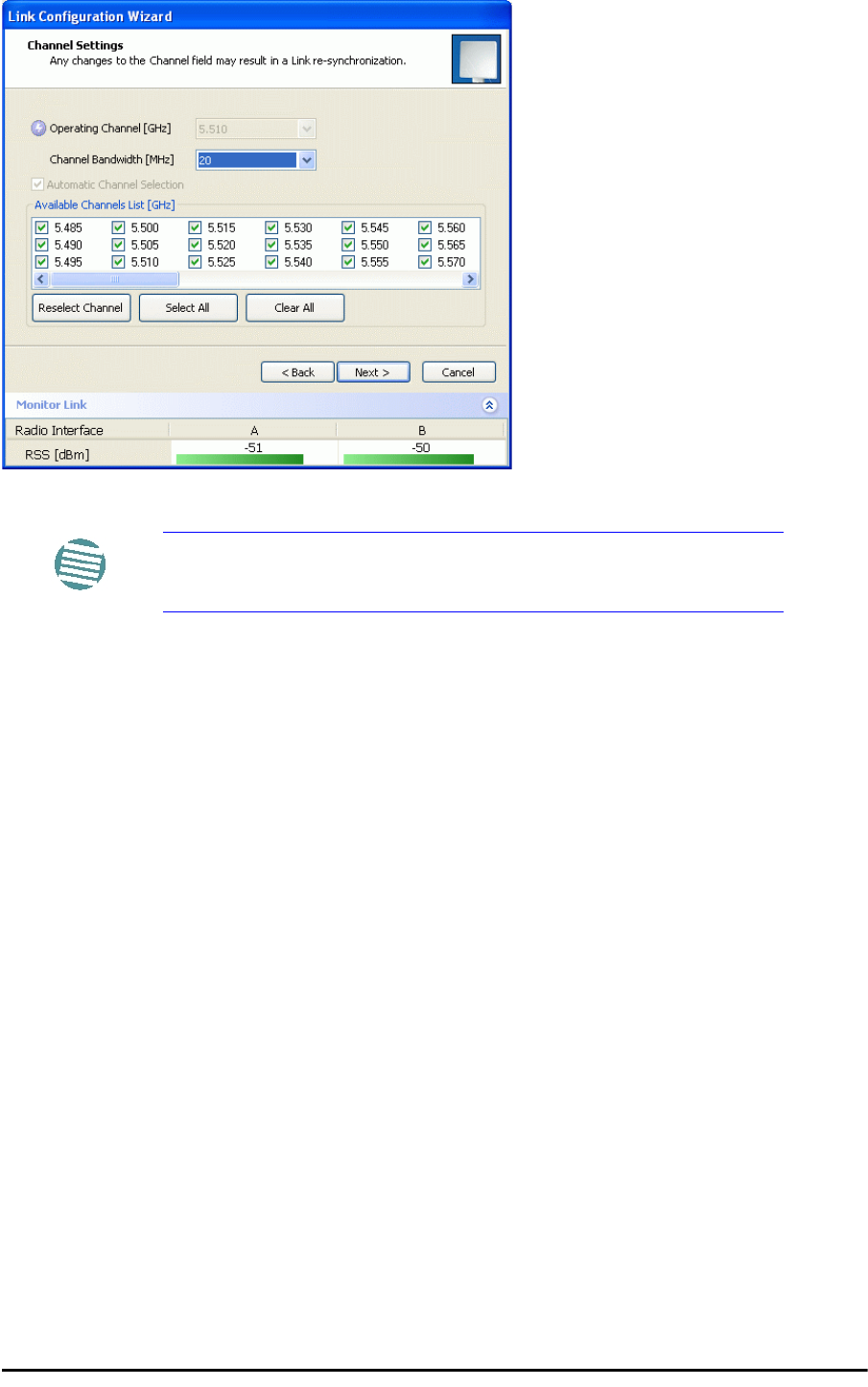
FCC/IC 5.4/5.3 GHz Link Configuration Chapter 16
RADWIN 2000 User Manual Release 2.5.40 16-5
Figure 16-5: Channel Select dialog box - ACS permanently enabled
Upon completion of the wizard, the Site configuration dialogs can be used in the usual way.
Once operational, the RADWIN Manager window is the same as for other radio equipment
models.
Here is the RADWIN Manager main window upon completion of the wizard:
Note
ACS cannot be disabled.
FCC/IC 5.4/5.3 GHz Link Configuration Chapter 16
RADWIN 2000 User Manual Release 2.5.40 16-6
Figure 16-6: FCC/IC 5.4/5.3 GHz operational

RADWIN 2000
Broadband Wireless Transmission System
USER MANUAL
RELEASE 2.5.40
Part 4: Field Installation
Topics
UM 2000-2540/02.11

RADWIN 2000 User Manual Release 2.5.40 17-1
Chapter 17
Pole and Wall Installation
ODU Mounting Kit Contents
Table 17-1: Bill of Materials: ODU mounting kit
Item Qty
Large Clamp (see Figure 17-1)1
Small Clamp (see Figure 17-2)1
Arm (see Figure 17-3)1
Screw hex head M8x40 4
Screw hex head M8x70 2
Washer flat M8 4
Washer spring M8 3
M8 Nuts 2
Figure 17-1: Large Clamp Figure 17-2: Small Clamp Figure 17-3: Arm
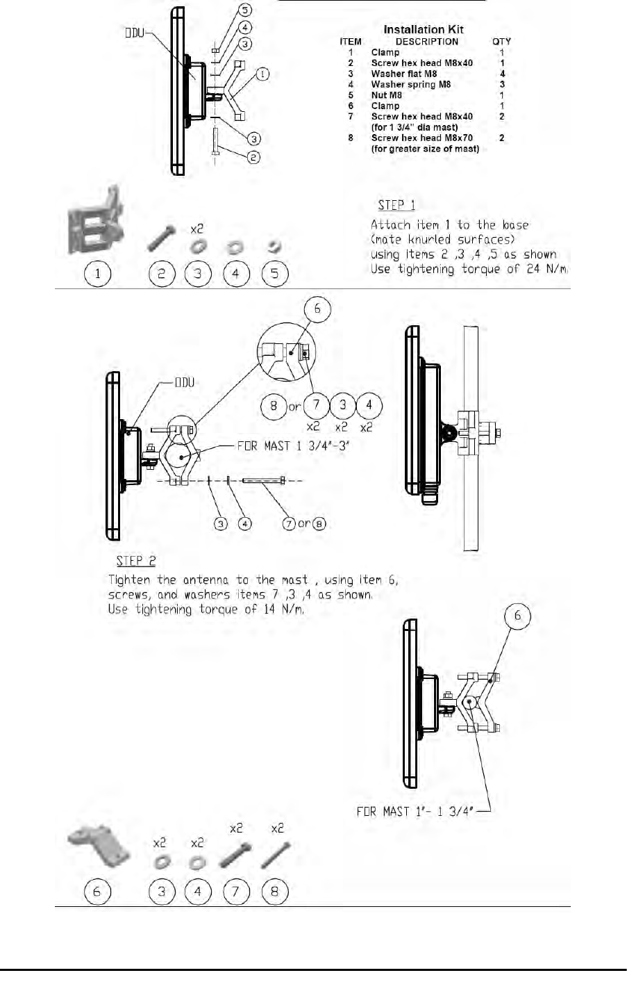
Mounting an ODU on a Pole Chapter 17
RADWIN 2000 User Manual Release 2.5.40 17-2
Mounting an ODU on a Pole
Figure 17-4: Mounting on a pole
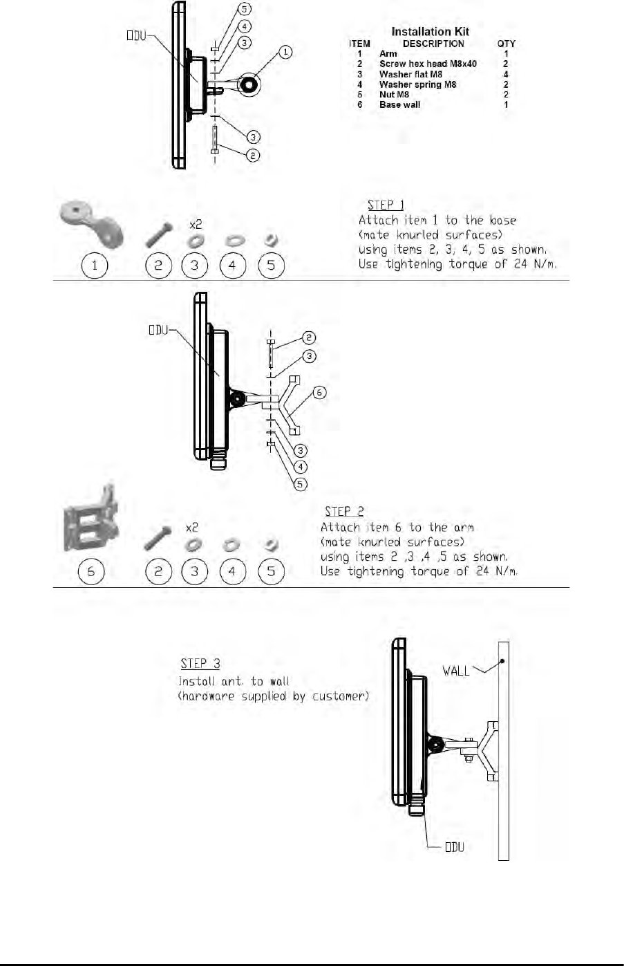
Mounting an ODU on a Wall Chapter 17
RADWIN 2000 User Manual Release 2.5.40 17-3
Mounting an ODU on a Wall
Figure 17-5: Mounting on a Wall
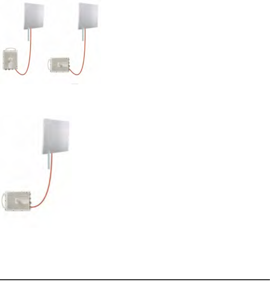
Mounting an External Antenna Chapter 17
RADWIN 2000 User Manual Release 2.5.40 17-4
Mounting an External Antenna
Optional external antennas can be mounted on a pole. The external mounting kit varies
according to the specific antenna model.
Mounting a Connectorized ODU Horizontally
What follows applies to both WinLink 1000 and RADWIN 2000 with obvious differences.
An ODU may be mounted horizontally as shown in Figure 17-6.
To mount an ODU horizontally, observe the following cautions:
1. To ensure your warranty rights for horizontally installed ODUs, make sure that the
four ports ANT1, ANT2, HSS and ODU are firmly secured or moisture sealed with the
supplied caps.
2. Further, ensure that cables are connected using a “water nose” as shown in
Figure 17-6.
Figure 17-6: Mounted ODUs with correct “water nose”
Do not do this:
Figure 17-7: Incorrectly mounted ODU (No “water nose”)
3. If you attach an external PoE device near the ODU, the same considerations apply.
RADWIN 2000 User Manual Release 2.5.40 18-1
Chapter 18
Lightning Protection and
Grounding Guidelines
Meticulous implementation of the guidelines in this chapter will provide best protection
against electric shock and lightning.
The RADWIN Lightning Protection System consists of the following components:
• Grounding for the antenna coax cable
• Grounding for each IDU and ODU
• External Primary Surge Suppressor units and grounding for the outdoor cable
• Internal ESD protection circuits over the Power/Telecom lines
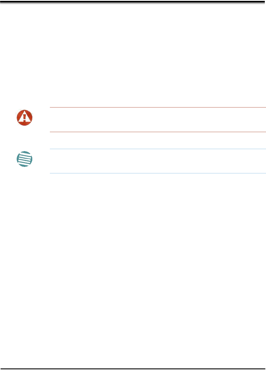
Grounding for Antenna Cable
A Grounding Kit must be connected to the coax antenna cable and reliably grounded. The
grounding kit is an Andrew Type 223158-2 (www.andrew.com). See Figure 18-1 below.
Warning
100% protection is neither implied nor possible.
Note
This chapter is at best a guide. The actual degree of lightning protection
required depends on local conditions and regulations.
Grounding for Indoor/Outdoor Units Chapter 18
RADWIN 2000 User Manual Release 2.5.40 18-2
Figure 18-1: Grounding antenna cables
Grounding for Indoor/Outdoor Units
ODU Grounding
RADWIN Lightning Protection System uses a Shielded CAT-5e cable to interconnect the Out-
door (ODU) and Indoor (IDU) units.
However, this shielding does not provide a good lightning discharge path, since it can not tol-
erate the high Lightning Current surges.
To provide an alternate Lightning Discharge path, the ODU and antenna grounding posts
should be connected to ground point by a 10 AWG short copper wire.
The device should be permanently connected to ground.

IDU Grounding Chapter 18
RADWIN 2000 User Manual Release 2.5.40 18-3
IDU Grounding
The IDU’s grounding post should be connected to the internal ground point, using a ground-
ing wire of at least 10 AWG. The grounding wire should be connected to a grounding rod or
the building grounding system.
The device should be permanently connected to ground.
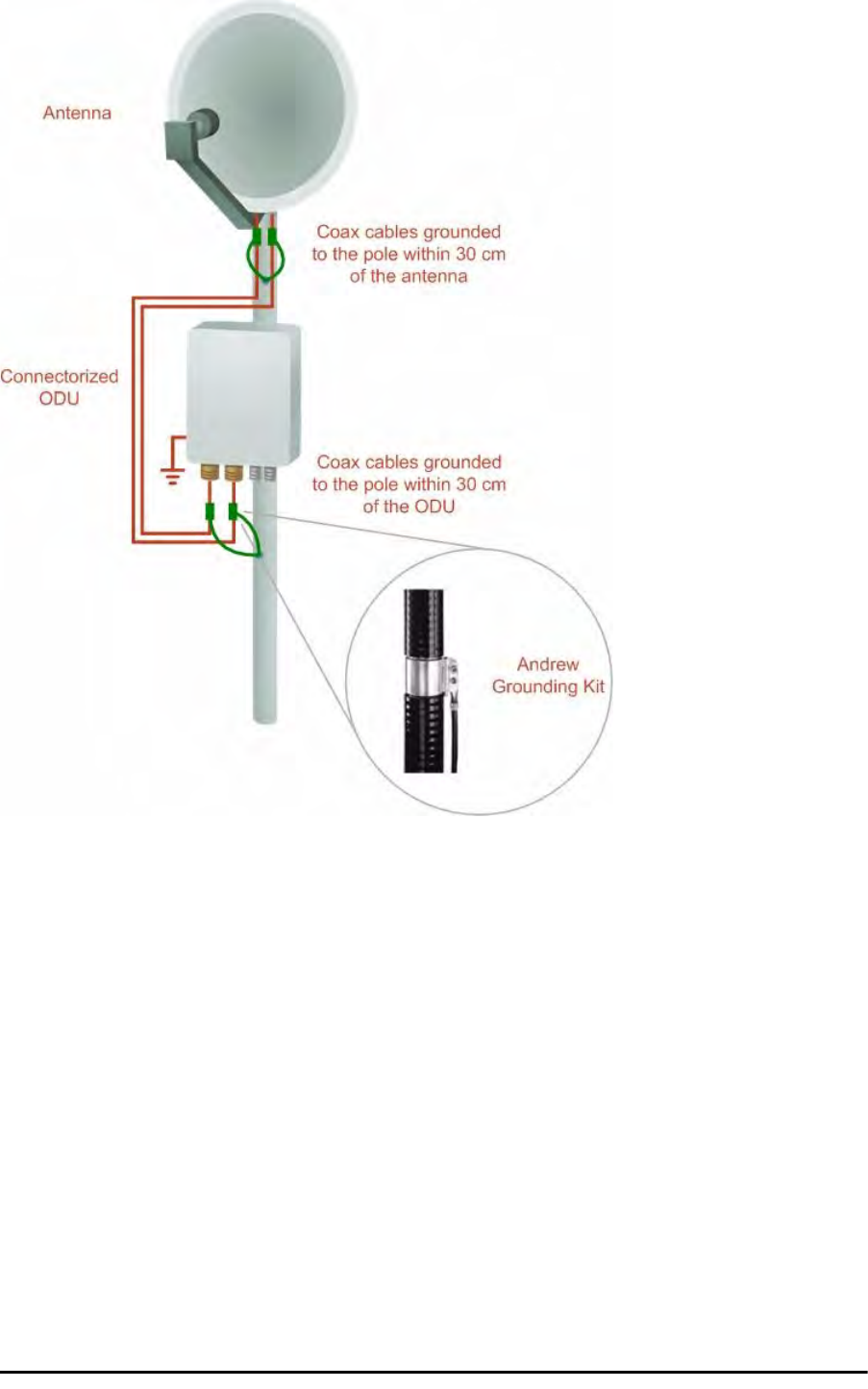
External Lightning Surge Suppressors and Grounding
A Grounding Kit and Surge Arrestor Unit must be located near the ODU and properly
grounded as illustrated in Figures 18-2 and 18-3 below:
External Lightning Surge Suppressors and Grounding Chapter 18
RADWIN 2000 User Manual Release 2.5.40 18-4
Figure 18-2: Grounding a typical pole installation
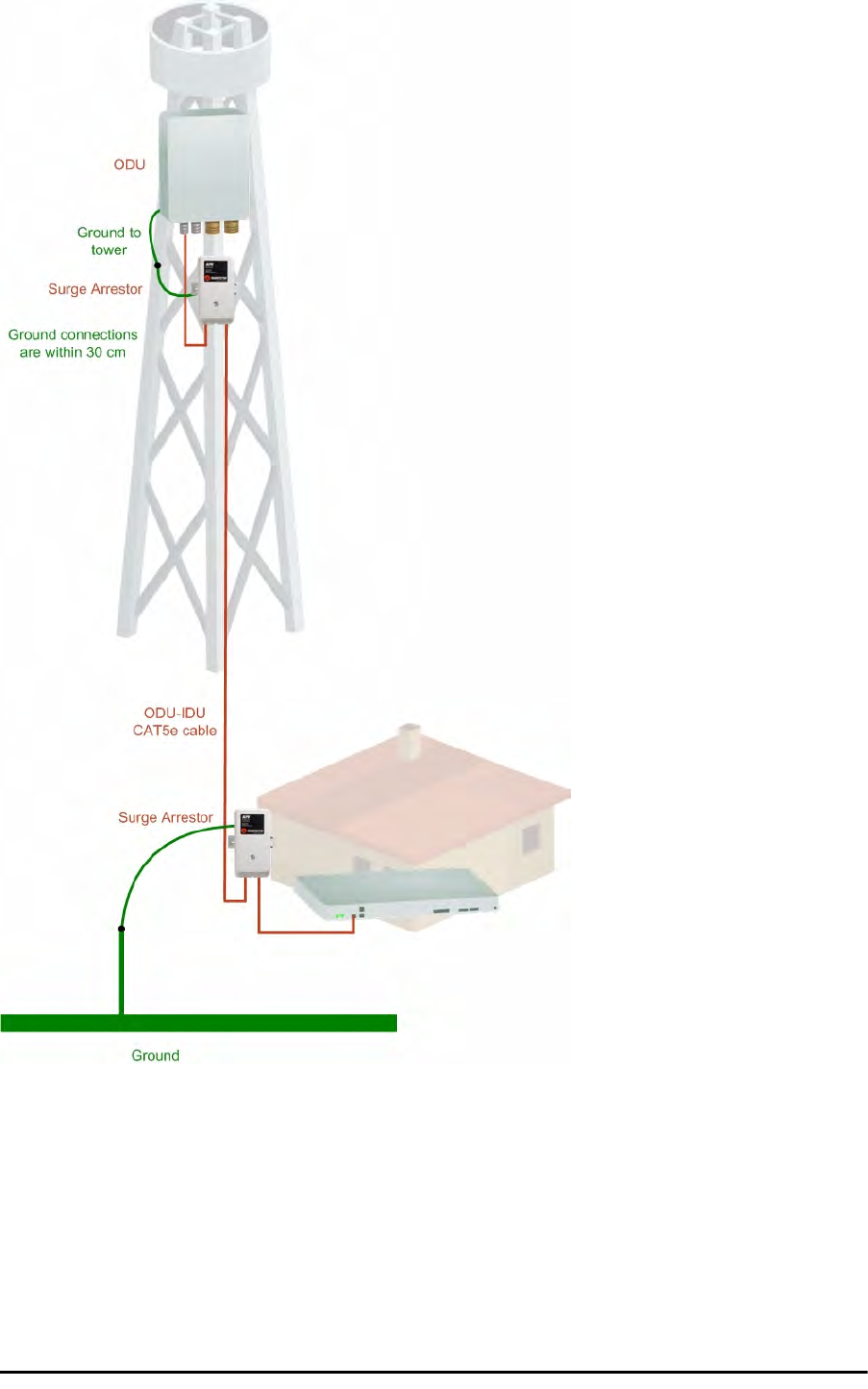
External Lightning Surge Suppressors and Grounding Chapter 18
RADWIN 2000 User Manual Release 2.5.40 18-5
Figure 18-3: Grounding a typical wall installation
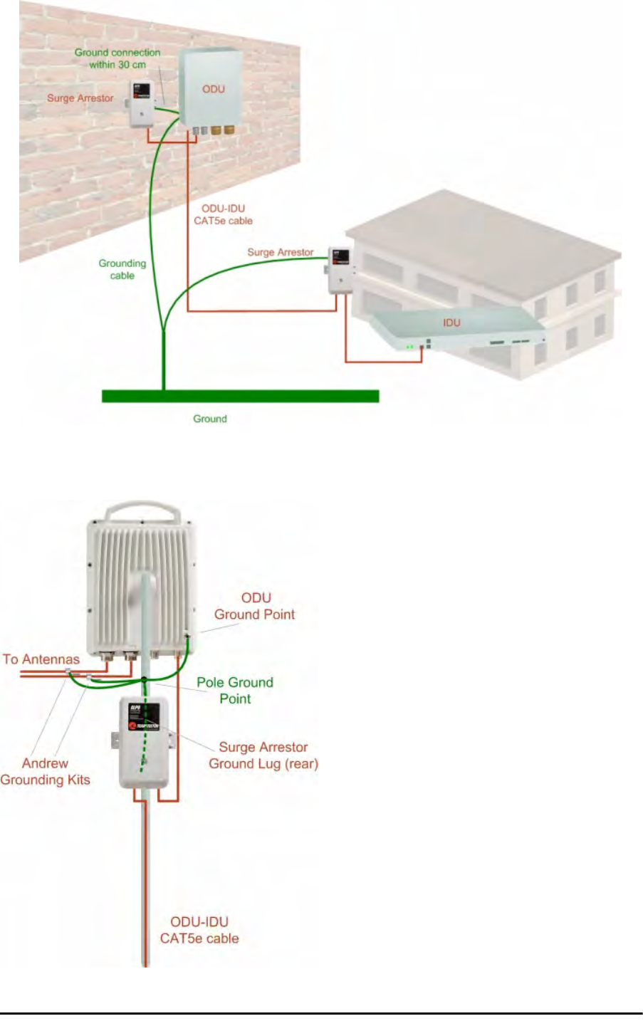
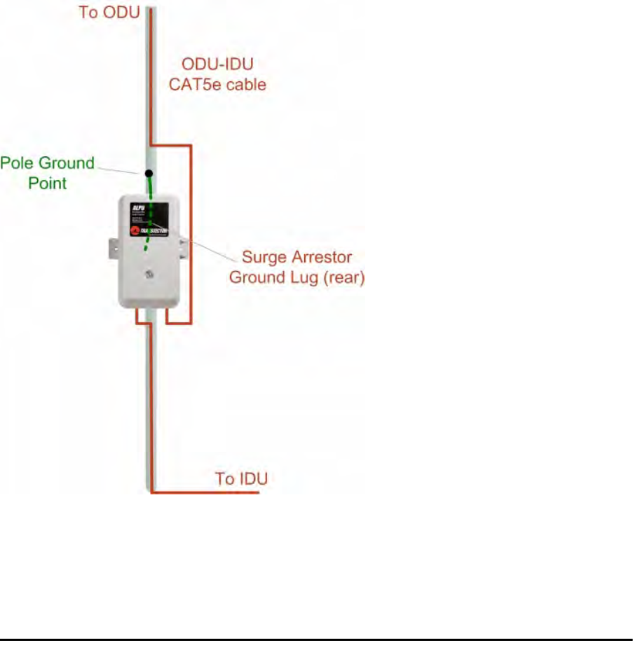
The next figure shows a close-up of the rear of grounded ODU:
Figure 18-4: ODU Surge Suppressor and grounding

External Lightning Surge Suppressors and Grounding Chapter 18
RADWIN 2000 User Manual Release 2.5.40 18-6
The Transtector protection circuits shown in Figure 18-5 below, utilize silicon avalanche
diode technology. The unit consists of an outdoor rated NEMA 3R type enclosure with easy
mounting flanges, ground stud attachment and easy wiring.
The ALPU-POE features RJ-45 protection circuits for the ODU-IDU data pairs (pins 1,2 & 3,6)
and DC power (pins 4,5 & 6,7 with the pairs bonded).
The unit is designed to be wall mounted. An optional set of bracket is available from the man-
ufacturer to allow a wide range of pole mount applications. A dedicated ground stud is pro-
vided inside the unit that must be bonded to the nearest grounding system (or Master Ground
bar) for proper surge protection.
The system wiring is installed with RJ-45 type connectors that can feed directly into the chas-
sis without having to cut, splice or route through awkward strain relief holes.
Figure 18-5: Transtector’s Surge Suppressor
To mount the lightning protection devices:
1. Mount the device as close to the ODU as possible. Mount the unit so that the cable
connectors are at the bottom (to prevent water from penetrating), with the strain
reliefs facing the ground.
2. Remove the cover by unscrewing the front of the unit.
3. Mount the unit to an outside surface using the two mounting holes.
4. Connect the ODU-IDU cable using the RJ-45 jack.
5. Connect one cable between the ODU and the suppressor using an RJ-45 jack.
6. Connect the suppressor’s ground stud to a grounding point. Use the appropriate wire
gauge and type, keeping the wire as short as possible, less than 1m (3’), between
the stud and the site grounding point.
7. Replace the cover.
Note
There may also be regulatory requirements to cross bond the ODU-IDU CAT-
5e cable at regular intervals up the mast. This may be as frequent as every
10 meters (33 feet).
External Lightning Surge Suppressors and Grounding Chapter 18
RADWIN 2000 User Manual Release 2.5.40 18-7
A second Surge Arrestor Unit should be mounted at the building entry point and must be
grounded, as shown in Figure 18-3 above.
To mount the lightning protection at the building entry point:
1. Mount the device outside the building, located as near as possible to the entrance of
the CAT-5e ODU-IDU cable. Mount the unit so that the cable connectors are at the
bottom (to prevent water from penetrating), with the strain reliefs facing the ground.
2. Remove the cover by unscrewing the front of the unit.
3. Mount the unit to an outside surface using the two mounting holes.
4. Connect the ODU-IDU cable using the RJ-45 jack.
5. Connect one cable between the IDU and the suppressor using an RJ-45 jack.
6. Connect the suppressor’s ground stud to a grounding point. Use the appropriate wire
gauge and type, keeping the wire as short as possible, less than 1m (3’), between
the stud and the site grounding point.
7. Replace the cover
Figure 18-6: Surge Suppressor and grounding at building entry point

Internal ESD Protection circuits Chapter 18
RADWIN 2000 User Manual Release 2.5.40 18-8
Internal ESD Protection circuits
RADWIN equipment is designed to meet the ETSI/FCC/Aus/NZ/CSA EMC and Safety require-
ments. To fulfill these requirements, the system's Telecom lines at the ODU/IDU are Trans-
former-isolated and include internal ESD (Electro-Static-Discharge) Protection circuits.

RADWIN 2000 User Manual Release 2.5.40 19-1
Chapter 19
Preloading an ODU with
an IP Address
Why this is Needed?
All ODUs supplied by RADWIN come pre-configured with an IP address of 10.0.0.120. For use
in a network, the ODUs must be configured with suitable static IP addresses. The method for
doing this under office conditions is set out in Chapter 5.
There are two situations under which ODUs may need to be pre-loaded with an IP address
prior to installation to a link:
• Changing an individual ODU in the field
• Preparing a large number of ODUs in a warehouse prior to deployment in the field,
according to a network installation plan.
This chapter explains how do this.
Required Equipment
The minimal equipment required to pre-load an ODU with an IP address is:
• Laptop computer (managing computer) satisfying the requirements of Table 4-1
• An installed copy of the RADWIN Manager
• A PoE device
• A crossed Ethernet LAN cable
• An IDU-ODU cable
• If you have connectorized ODUs, two N-type RF terminators
Caution
Do not carry out this procedure using a multi homed managing computer
also connected to a network. It will flood the network with broadcast
packets. Further, it will throw any other links on the network into Installation
mode.
The procedure Chapter 19
RADWIN 2000 User Manual Release 2.5.40 19-2
The procedure
To Preolad an ODU with an IP address:
1. Using the IDU-ODU cable, connect the PoE device to the ODU, ensuring that the
cable is plugged into the PoE port marked P-LAN-OUT.
2. For connectorized ODUs, screw the RF terminators into the two antenna ports.
3. Connect the Poe device to AC power.
4. Using a crossed LAN cable, connect the LAN-IN port of the PoE device to the Ethernet
port of the managing computer. The ODU will commence beeping at about once per
second, indicating correct operation.
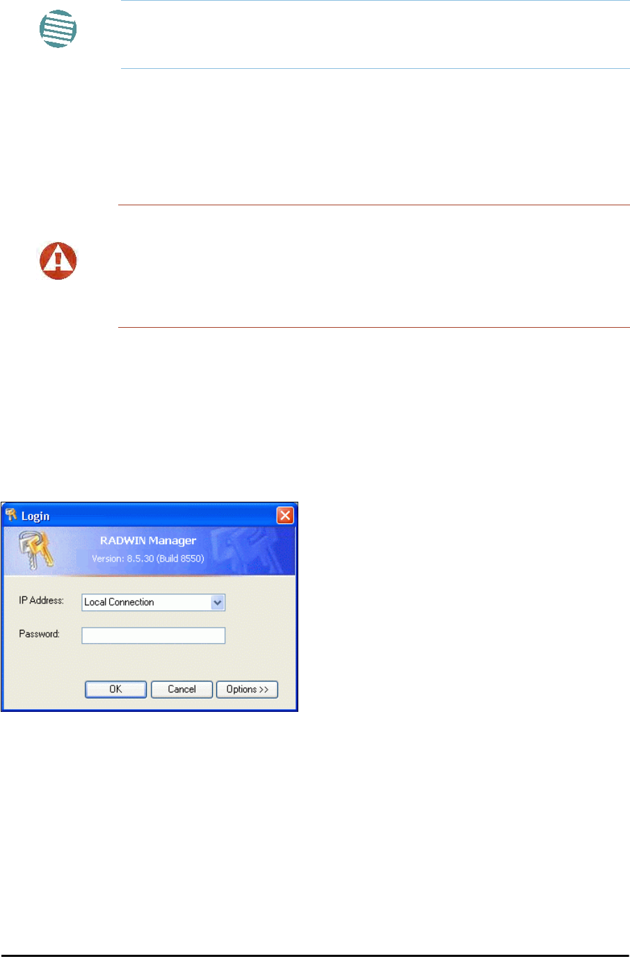
5. Launch the RADWIN Manager.
6. At the log on window, choose Local Connection.
Figure 19-1: Log on Window for Local Connection
7. Enter the default password,
admin
. After a few moments, the RADWIN Manager
main window appears:
Note
The following procedure is generic to all RADWIN radio products. What you
see on your running RADWIN Manager may differ in some details from the
screen captures used to illustrate this chapter.
Warning
A powered up ODU emits RF radiation from the antenna port (or connected
antenna). When working with a powered up connectorized ODU, always use
RF terminators.
For an ODU with an integrated antenna, ensure that the antenna is always
directed away from other people.
The procedure Chapter 19
RADWIN 2000 User Manual Release 2.5.40 19-3
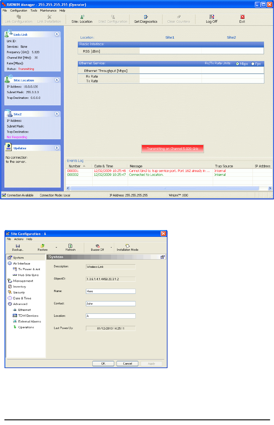
Figure 19-2: Opening RADWIN Manager window prior to installation
8. Click the un-grayed Site:Location button. The following dialog window appears:
Figure 19-3: Configuration Dialog Box
9. Click the Management item in the left hand panel. The following window is pre-
sented:
The procedure Chapter 19
RADWIN 2000 User Manual Release 2.5.40 19-4
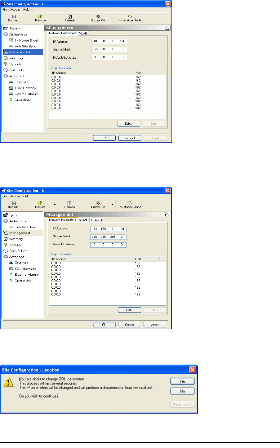
Figure 19-4: Management Addresses - Site Configuration dialog box
10. Enter the IP Address, Subnet Mask and Default Gateway as requested. For example,
the ODU used here is to be configured as follows:
Figure 19-5: ODU with IP Addressing configured
11. Click OK. You are asked to confirm the change:
Figure 19-6: Confirmation of IP Address change
The procedure Chapter 19
RADWIN 2000 User Manual Release 2.5.40 19-5
12. Click Yes to accept the change. After about half a minute the changes will be reg-
istered in the ODU. On the left hand panel of the main window, you will see the new
IP configuration for the ODU.
Figure 19-7: Main Window after IP Address change
13. Click Cancel to leave the open Management dialog. You may now exit the RADWIN
Manager, or connect to another ODU. If you choose to connect to another ODU,
after about a minute, the main window of the RADWIN Manager will revert to that
shown in Figure 19-2 above. In any event, power down the changed ODU; your
changes will take effect when you power it up again.
Note
Some additional things you may want to do now:
•Go to Site Installation | Air Interface. You can enter a Link ID
and change the Installation Frequency and Channel Bandwidth.
• If you log on as Installer, you can change the default band (Chapter
20).
Note
Don’t forget to remove the RF terminators from a connectorized ODU after
powering it down.

Tip: How to Recover a Forgotten ODU IP Address Chapter 19
RADWIN 2000 User Manual Release 2.5.40 19-6
Tip: How to Recover a Forgotten ODU IP Address
If you have an ODU with lost or forgotten IP address, use the above procedure to log on to it
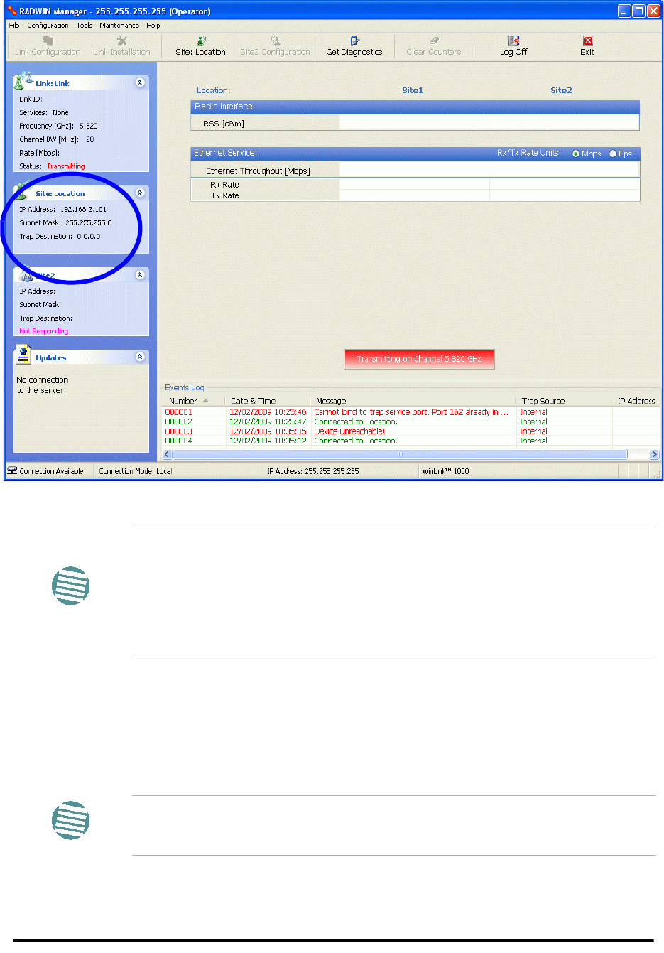
using Local Connection. The IP address will appear in the left hand status area:
Figure 19-8: Existing IP address displayed after log-on with Local Connection

RADWIN 2000 User Manual Release 2.5.40 20-1
Chapter 20
Changing the Factory
Default Band
Why this is Needed
All ODUs supplied by RADWIN come with pre-configured with a factory default product-
dependent band according to the ODU part number.
For ODUs supporting Multi-band, it may be changed using the procedure in this chapter. The
procedure is generic, applying to all ODUs with the Multi-band feature.
Required Equipment
The minimal equipment required to change an ODU default band is:
• Laptop computer (managing computer) satisfying the requirements of Table 4-1.
• An installed copy of the RADWIN Manager
• A PoE device
• A crossed Ethernet LAN cable
• An IDU-ODU cable
The procedure
To change the factory default band:
1. Using the IDU-ODU cable, connect the PoE device to the ODU, ensuring that the
cable is plugged into the PoE port marked P-LAN-OUT.
Caution
• If for some reason the default band needs to be changed, it should
be done before link installation.
• Use of an incorrect band may be in violation of local regulations.
Note
The following procedure is generic to all relevant RADWIN radio products.
What you see on your running RADWIN Manager may differ in some details
from the screen captures used to illustrate this chapter.
The procedure Chapter 20
RADWIN 2000 User Manual Release 2.5.40 20-2
2. Connect the Poe device to AC power.
3. Using a crossed LAN cable, connect the LAN-IN port of the PoE device to the Ethernet
port of the managing computer. The ODU will commence beeping at about once per
second, indicating correct operation.
4. Launch the RADWIN Manager.
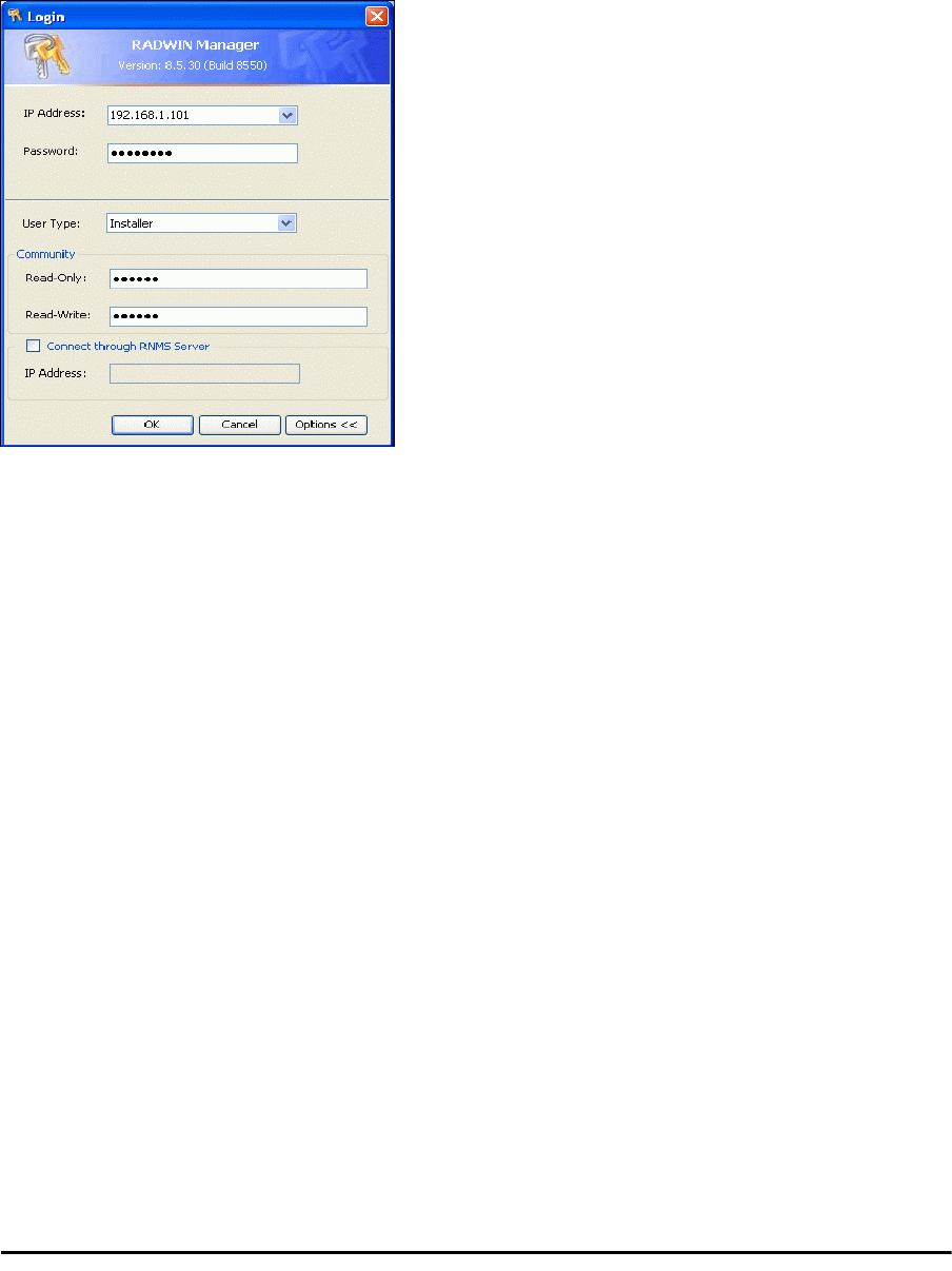
5. Log on as Installer.
Figure 20-1: Becoming Installer
6. Enter the default password,
wireless
. After a few moments, the RADWIN Manager
main window appears:
The procedure Chapter 20
RADWIN 2000 User Manual Release 2.5.40 20-3
Figure 20-2: Opening RADWIN Manager window prior to band change (default circled)
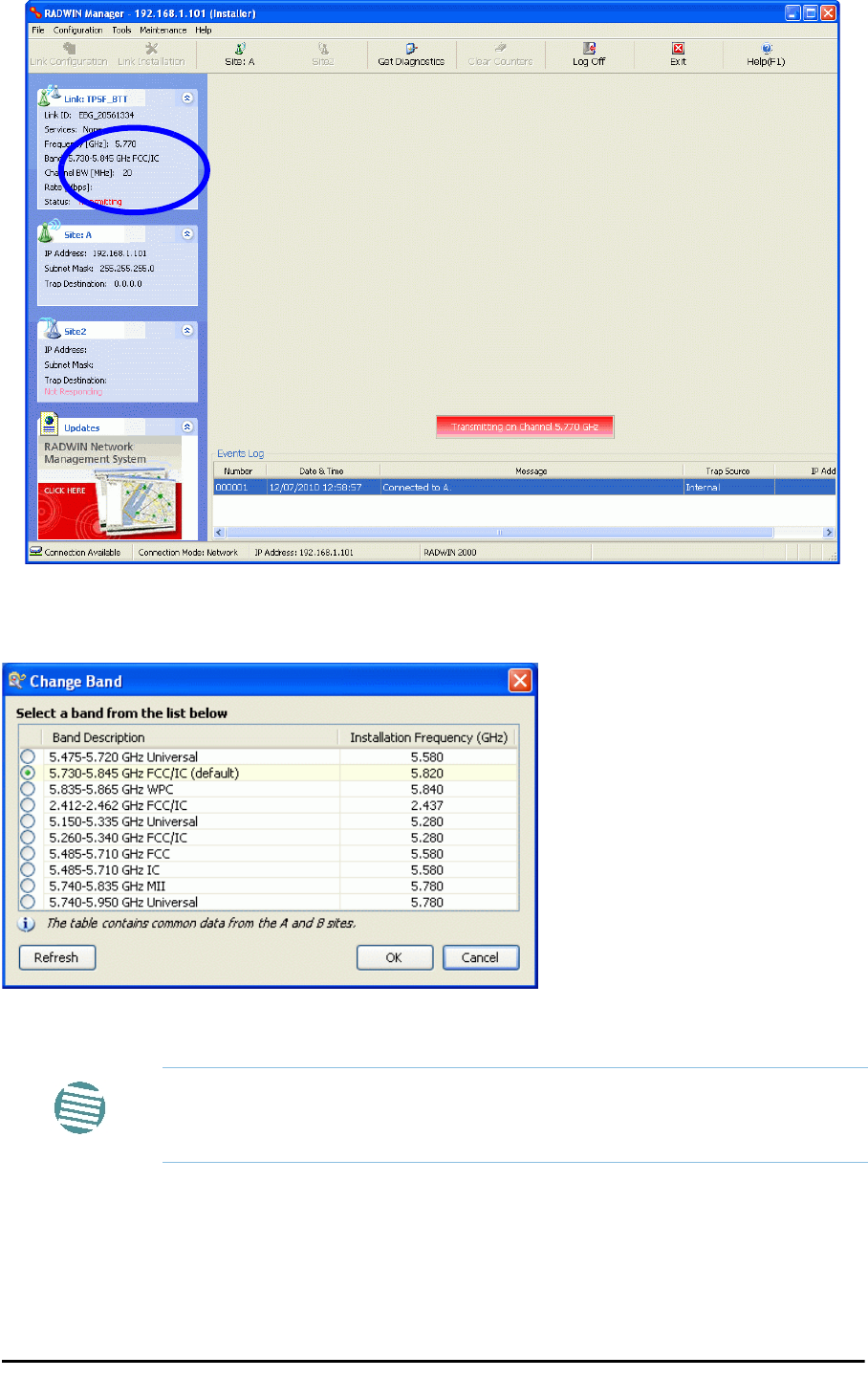
7. Click Tools | Change Band. The following window appears:
Figure 20-3: Change Band dialog
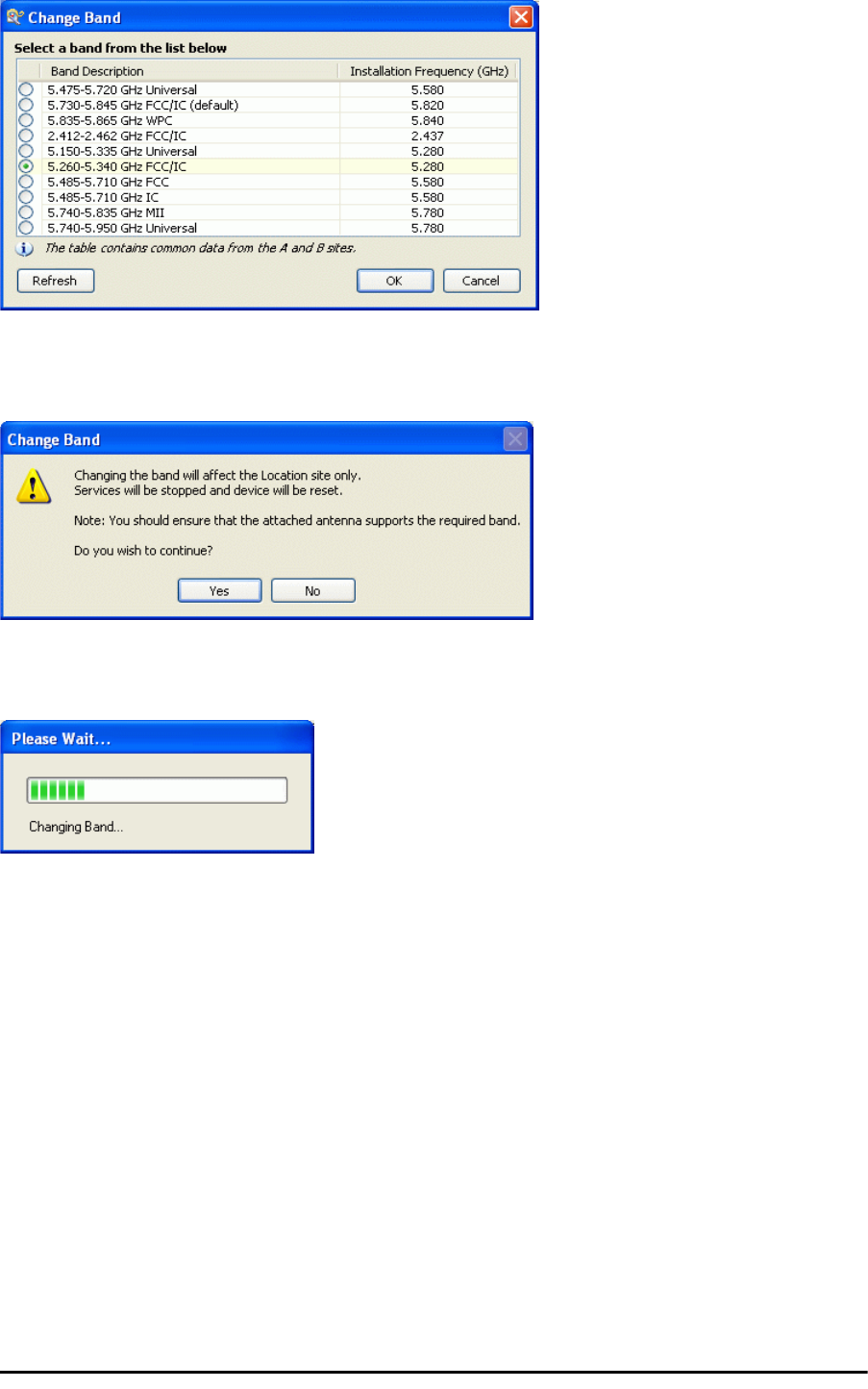
8. Click the band required:
Note
The bands appearing in Figure 20-3 are product dependent. To see which
bands are available for your product, check your product Inventory (see
Figure 8-8) and then consult RADWIN Customer Support.
The procedure Chapter 20
RADWIN 2000 User Manual Release 2.5.40 20-4
Figure 20-4: A different band selected
9. The Change Band warning is displayed. Click Yes to continue.
Figure 20-5: Change Band confirmation
The change, which may take some time, is carried out:
The result is reflected in the RADWIN Manager main window:
Changing Band for DFS Chapter 20
RADWIN 2000 User Manual Release 2.5.40 20-5
Figure 20-6: Main Window after band change - new band circled
Changing Band for DFS
Changing to a DFS band is similar to the foregoing procedure.
As soon as you establish a link using a DFS band, you are offered Configuration only in the
main menu. Installation mode is disabled.
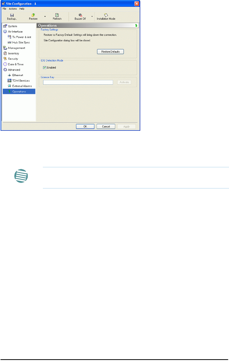
Special Products or Features: Entering a License Key
If you go to the Operations window as Installer (Figure 20-7), you will see a provision for
entering a license key. Should you ever require such a key, the procedure is as follows:
To enter a License key:
1. Log on as Installer (as for the previous procedure).
2. Click the Site:Location tool bar button from the main tool bar.
Note
If you carry out this operation on a link, the band is effective on both sites
and you are placed in installation mode.
Provisions for Licensed 3.X and 2.5 GHz Bands Chapter 20
RADWIN 2000 User Manual Release 2.5.40 20-6
Figure 20-7: Using the Operations window to enter a license key
3. Enter your license key and click Activate.
4. When it is accepted, click Cancel.
Provisions for Licensed 3.X and 2.5 GHz Bands
Overview
3.X Bands
The new RADWIN 2000 C and RADWIN 2000 X series add additional bands in the 3.X GHz
range to those in Release 2.5.00. The new supported bands fall into two categories: The first
category consists of those falling under the ubiquitous FCC, IC or ETSI regulation. The second
category is referred to as RADWIN Universal bands. These bands are known to be regulated
but the numerous combinations of regulation and location preclude specific support.
Release 2.5.40 introduces support for the band 3.3-3.8 GHz as follows:
• FCC part 90 subpart Z and IC RSS-197 supporting 3.650-3.700 GHz
• 3.650 -3.675 GHz in Restricted mode
• Hardware ready for the Unrestricted Mode band operating in all 50 MHz of the
3.650-3.700 GHz band
• IC RSS-192 supporting 3.475 – 3.650 GHz
• ETSI 3.4 -3.7 GHz split into three sub-bands, 3.650-3.675 GHz, 3.475-3.650 GHz and
3.590-3.710 GHz
Note
License keys, where appropriate, are obtainable from RADWIN Customer
Support.

Terminology Recap Chapter 20
RADWIN 2000 User Manual Release 2.5.40 20-7
• RADWIN Universal 3.300-3.800 GHz.
Integrated and connectorized products are available. All of them are multiple band with the
default band being 3.650-3.675 GHz other than the ETSI 3.4 - 3.7 GHz models.
The new products may be operated under 5, 10 and 20 MHz channel bandwidths and are
broadly compatible with the full feature set of RADWIN 2000.
To meet regulatory requirements, a somewhat different procedure is required to set up links
using these bands.
2.5GHz Bands for BRS/EBS
The rationale for these bands and relevant details are described in Chapter 24. The installa-
tion method ids the same as for other licenced FCC bands as described below.
Terminology Recap
•3.X Universal bands refer to RADWIN Universal bands as described above
•3.X or 3.X GHz refers to the frequency range 3.300 – 3.800GHz
•A 3.X ODU is an ODU pre configured to operate in the 3.X GHz licensed bands
•A 3.X Link in a RADWIN 2000 link using a pair of 3.X ODUs
•High Resolution Bands - Channel minimum step is 250 KHz. Applies to 3.475 -
3.650 GHz IC RSS-192, 3.4 -3.7 GHz ETSI and the 3.3 - 3.8 GHz Universal band.
•Low Resolution Bands - Channel minimum step is 1 MHz. Applies to FCC regula-
tions in the 3.650-3.675 GHz band.
•Inactive Mode - An ODU is powered up, in communication with a managing com-
puter but not transmitting. It is required where regulation does not permit the use of
RADWIN’s default Installation Mode frequency and channel bandwidth. The ODU may
transmit using the licensed or registered band, channel bandwidth and permitted Tx
power.
•Regular Mode - The usual default Installation Mode
Regulatory Considerations for 3.650-3.675 GHz FCC/IC part 90 sub
part Z
Restricted Mode
The band is supported in accordance with 3.650-3.675 FCC/IC part 90 subpart Z:
RADWIN Ltd. conforms to FCC DA 07-4605 (November 14, 2007) FCC-certified with FCC-ID:
Q3KRW2030 and supporting the following equipment requirements:
“Restricted contention protocols can prevent interference only with other devices incorporat-
ing the same or similar protocols. Equipment using a restricted protocol can operate only on
the lower 25 megahertz (3650-3675 MHz)."

Regulatory Considerations for 3.650-3.675 GHz FCC/IC part 90 sub part Z Chap-
RADWIN 2000 User Manual Release 2.5.40 20-8
Transmission power options
Table 20-1shows the extent of compliance by RADWIN 2000 C products to FCC/IC power
limits, having regards to antenna type and transmission power options.
Higher Transmission Power Options and Restrictions:
Table 20-2 defines the maximum transmission power and EIRP limits for the specified fre-
quency and channel bandwidths.
It specifies the power limits to be used by the operator when assigning center frequencies.
Table 20-1: FCC/IC compliance by antenna and transmission power
Measured
Frequency Power
Antenna Nominal
CBW
Low Center
Frequency
Channel
[MHz]
High Center
Frequency
Channel
[MHz]
Max
Conducted Tx
Power per
Pole [dBm]
Total
Conducted
Max Tx Power
[dBm]
Max EIRP
[dBm]
21dBi INT
5 MHz 3653 3672 11.14 14.14 35.14
10 MHz 3655 3670 14.46 17.46 38.46
20 MHz 3660 3665 17.36 20.36 41.36
21dBi EXT (22dBi-
1dB feeder)
5 MHz 3653 3672 11.14 14.14 35.14
10 MHz 3655 3670 14.46 17.46 38.46
20 MHz 3660 3665 17.36 20.36 41.36
24dBi EXT (25 -
1dB feeder loss)
5 MHz 3653 3672 8.65 11.65 35.65
10 MHz 3655 3670 11.36 14.36 38.36
20 MHz 3660 3665 13.73 16.73 40.73
Table 20-2: Higher Transmission Power Limits
Nominal
CBW
Low Center
Frequency
Channel [MHz]
High Center
Frequency
Channel [MHz]
Max Conducted
Tx Power per
Pole [dBm]
Total Conducted
Max Tx Power
[dBm]
Max EIRP
[dBm]
5 MHz 3653 3672 15.60 18.60 35.60
10 MHz 3655 3670 18.69 21.69 38.69
3656 3669 22.00 25.00 38.50
20 MHz 3660 3665 21.18 24.18 41.18
3661 3664 22.60 25.60 39.10

Band Splitting for ETSI 3.4 - 3.7GHz Chapter 20
RADWIN 2000 User Manual Release 2.5.40 20-9
Availability Summary for FCC/IC and Universal 3.X GHz
Band Splitting for ETSI 3.4 - 3.7GHz
The ETSI 3.4 - 3.7GHz band is split into three sub-bands reflecting the different Max Tx Power
allowed in each one. The details are shown in below:
Using he RADWIN Manager to set up a 3.X or BRS Link
Inactive and Active Mode
Low Resolution Band 3.X ODUs may be installed and configured in the usual way.
What follows applies to High Resolution Band ODUs.
To ensure compliance with the relevant license, 3.X ODUs for IC, ETSI and Universal must be
configured from an inactive mode where the ODU is powered up, in communication with a
managing computer but not transmitting.
Table 20-3: Availability for FCC/IC and Universal 3.X GHz
Products series Occupied
Band
GHz Regulation Mode Channel
Bandwidth
MHz
Max Tx
Power
dBm
Frequency
Step
KHz
RADWIN 2000 C
3.650-3.675 FCC/IC Regular
5, 10, 20 25 1000
3.475-3.650 IC Inactive 250
3.300-3.800 Universal Unlimited
RADWIN 2000 X
3.650-3.675 FCC/IC Regular
525 1000
3.475-3.650 IC Inactive 250
3.300-3.800 Universal Unlimited
Table 20-4: Band split for ETSI 3.4-3.7GHz
Products series Occupied
Sub-Band
GHz
Center
Frequency
GHz Mode Channel
Bandwidth
MHz
Max Tx
Power
dBm
Frequency
Step KHz
RADWIN 2000 C
3.403-3.490 3.413-
3.480
Inactive 5, 10, 20
16
2503.470-3.610
3.480
-
3.600
23(†)
3.590-3.710
3.600
-3.700 25(‡)
RADWIN 2000 X
3.403-3.490 3.413-
3.480
Inactive 5
16
2503.470-3.610
3.480
-
3.600
23(†)
3.590-3.710
3.600
-3.700 25(‡)
Note
(†) The 3.480 GHz frequency is overlaped, occuring in two different bands
as shown. If you wish to use the 3.480 GHz frequency, you should set Max
TX Powerto 16 dBm.
(‡) The 3.600 GHz frequency is overlaped, occuring in two different bands
as shown. If you wish to use the 3.600 GHz frequency, you should set Max
TX Powerto 23 dBm.
Using he RADWIN Manager to set up a 3.X or BRS Link Chapter 20
RADWIN 2000 User Manual Release 2.5.40 20-10
Setting up a link is a two stage procedure:
1. Activate the ODUs by individually by configuring the band, frequency and channel band-
width for the license
2. Complete link configuration in the usual way
To set up a 3.X or BRS ODU:
1. Log on to it as Installer (Operator sufficient for ETSI) and set the IP address as
shown in Chapter 19.
2. Navigate to Site:Location|Air Interface and enter the Link ID for the ODU.
3. Click OK to dismiss the Site Configuration window. Answer Yes to the following popup
message:
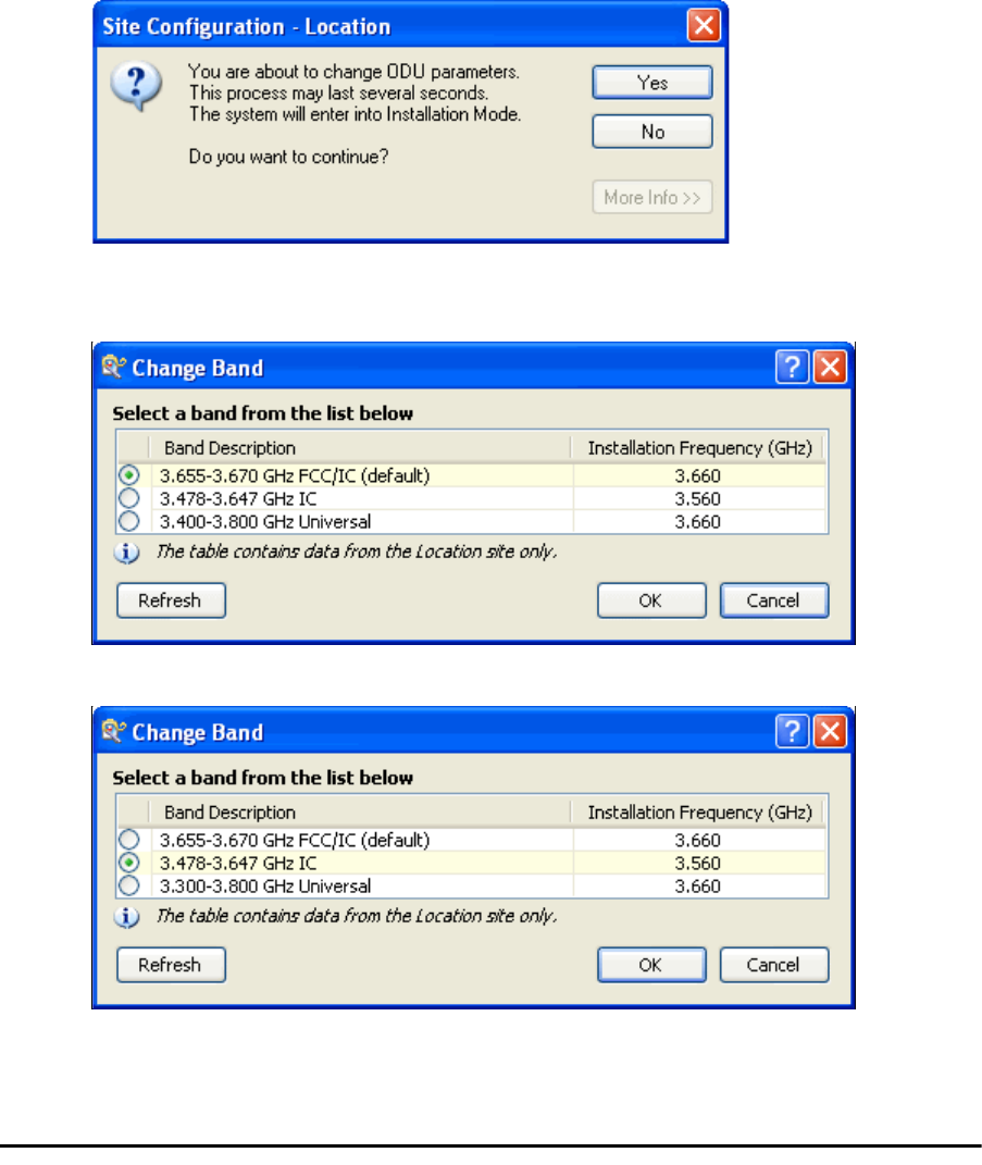
4. For ETSI models, skip to step 7 below. For all others, navigate to Tools|Change Band.
The following window is displayed:
5. Choose the required band. For illustration, we will choose the IC band.
6. Click OK to continue and accept the notification message which appears:
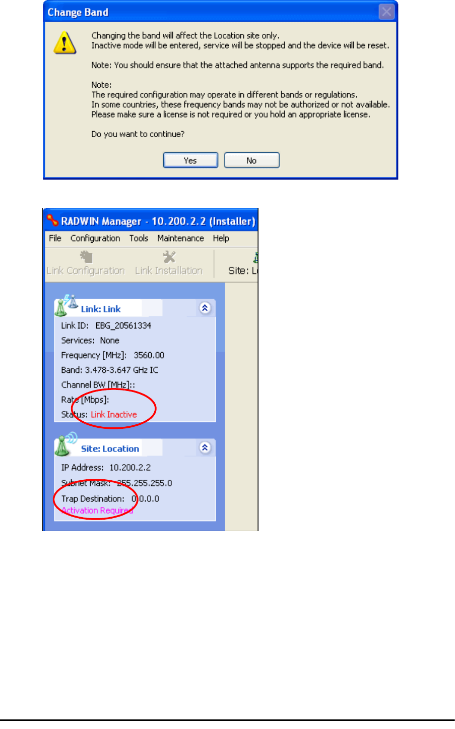
Using he RADWIN Manager to set up a 3.X or BRS Link Chapter 20
RADWIN 2000 User Manual Release 2.5.40 20-11
After a few seconds, the ODU goes into inactive mode:
7. Activate the ODU by navigating to Site:Location|Air Interface:
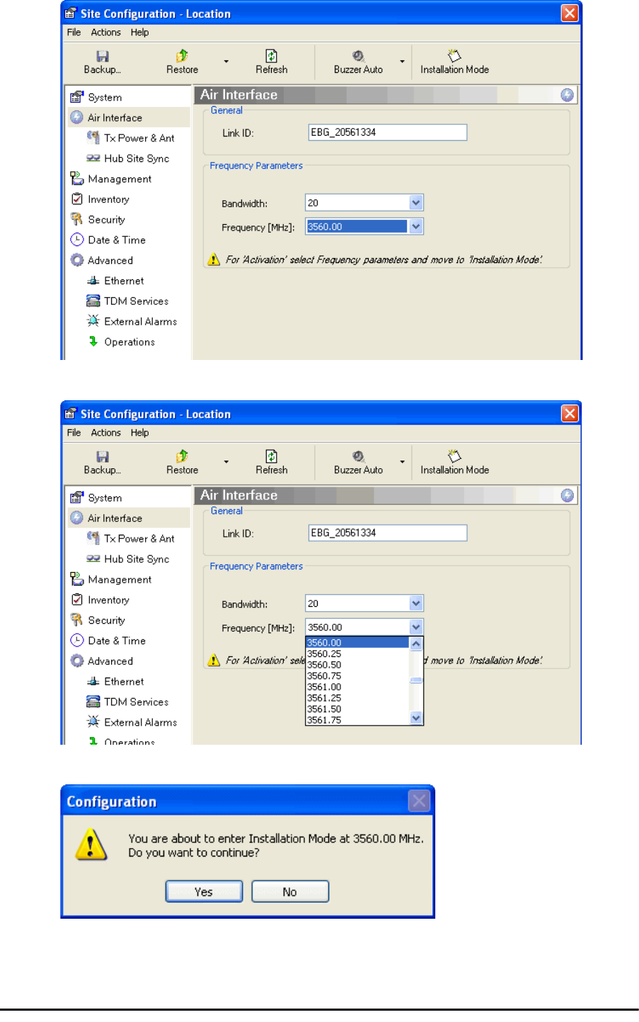
Using he RADWIN Manager to set up a 3.X or BRS Link Chapter 20
RADWIN 2000 User Manual Release 2.5.40 20-12
8. Choose a frequency from the drop down list:
9. Enter Installation Mode and confirm your choice:
10. After a few moments of processing, you may click OK to dismiss the Site Configura-
tion window. The ODU is now in normal Installation Mode:
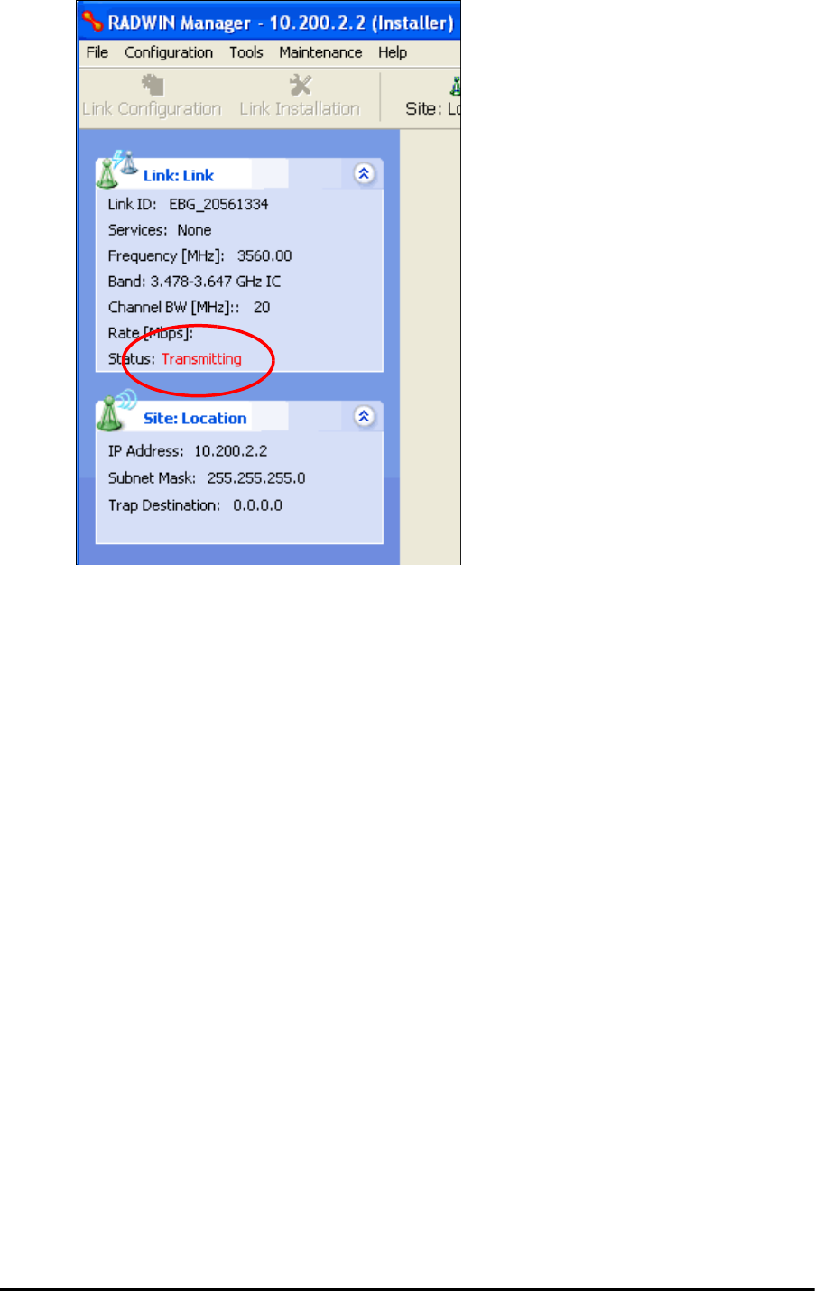
Using he RADWIN Manager to set up a 3.X or BRS Link Chapter 20
RADWIN 2000 User Manual Release 2.5.40 20-13
11. Repeat the above procedure for the second ODU in the link, ensuring that the Link
ID is entered correctly and the same band is chosen.
12. From this point, you may install both ODUs in the field according to the procedures
in this User Manual.

RADWIN 2000 User Manual Release 2.5.40 21-1
Chapter 21
Link Budget Calculator
Overview
The Link Budget Calculator is a utility for calculating the expected performance of the RAD-
WIN 2000 wireless link and the possible configurations for a specific link range.
The utility allows you to calculate the expected RSS of the link, and find the type of services
and their effective throughput as a function of the link range and deployment conditions.
User Input
You are required to enter or choose the following parameters. Depending on the product,
some of the parameters have a default value that cannot be changed.
• Band, which determines frequency and regulation
• Channel Bandwidth
• Tx Power (maximum Tx power per modulation is validated)
• Antenna Type (cannot be changed for ODU with integrated antenna)
• Antenna Gain per site (cannot be changed for integrated antenna)
• Cable Loss per site (cannot be changed for integrated antenna)
• Required Fade Margin
• Rate (and Adaptive check box)
• Service Type
• Required Range
Link Budget Calculator Internal Data
For each product (or Regulation and Band) the calculator stores the following data required
for link budget calculations:
• Maximum Transmit power (per modulation)
• Receiver Sensitivity (per modulation) for Ethernet service and for TDM services at var-
ious BER
• Maximum linear input power (used to calculate minimum distance)
• Antenna gain and cable loss for ODU with integrated antenna
• Available Channel Bandwidths

Calculations Chapter 21
RADWIN 2000 User Manual Release 2.5.40 21-2
Calculations
EIRP
Expected RSS and Fade Margin
where:
Site A is the transmitting site
Site B is the receiving site
PathLoss is calculated according to the free space model,
where Sensitivity is dependent on air-rate.
Min and Max Range
MinRange is the shortest range for which per air-rate.
MaxRange (with Adaptive checked) is the largest range for which
, at the highest air-rate for which this relationship is true. In a
link with adaptive rate this will be the actual behavior.
MaxRange (for a given air-rate) is the largest range for which
.
Service
The Ethernet and configured TDM trunks throughput is calculated according to internal prod-
uct algorithms.
Availability
The Service Availability calculation is based on the Vigants Barnett method which predicts the
downtime probability based on a climate factor (C factor).
EIRP TxPower AntennaGainSiteA CableLossSiteA
–+=
ExpectedRSS EIRP PathLoss AntennaGainSiteB CableLossSiteB
–+–=
PathLoss 32.45 20 frequencyMHz
20 RequiredRangeKm
10
log+
10
log+=
ExpectedFadeM inarg ExpectedRSS Sensitivity–=
ExpectedRSS MaxInputPower
ExpectedRSS Sensitivity
ExpectedRSS Sensitivity RequiredFadeM inarg+
Availability
16–10
7–
CfactorfrequencyGHz
RequiredRangeKM
3
10
ExpectedFadeM inarg–
10
------------------------------------------------------------
=

Antenna Height Chapter 21
RADWIN 2000 User Manual Release 2.5.40 21-3
Antenna Height
The recommended antenna height required for line of sight is calculated as the sum the
Fresnel zone height and the boresight height. See About the Fresnel Zone below. Using
the notation of Figure 21-1 below, splitting
ExpectedRange
into
d
1
+ d
2
, the
Fresnel zone
height
at distance
d
1
from the left hand antenna, is given by
For the most conservative setting, we take the mid-point between the antennas, setting
which gives
simplifying to .
The
boresight clearance height
is calculated as:
where .
About the Fresnel Zone
The Fresnel zone (pronounced "frA-nel", with a silent “s”) is an elliptically shaped conical zone
of electromagnetic energy that propagates from the transmitting antenna to the receiving
antenna. It is always widest in the middle of the path between the two antennas.
0.6
300
frequencyGHz
----------------------------------- d1d2
d1d2
+
-----------------------------------------------------------
d1d2ExpectedRange
2
-----------------------------------------
==
0.6
300
frequencyGHz
----------------------------------- ExpectedRange
2
----------------------------------------- 2
ExpectedRange
2
----------------------------------------- ExpectedRange
2
-----------------------------------------
+
--------------------------------------------------------------------------------------------
0.52 ExpectedRange
frequencyGHz
-----------------------------------------
R2Mean ExpectedRange
2
----------------------------------------- 2
+RMean
–
RMean 6367.4425Km=
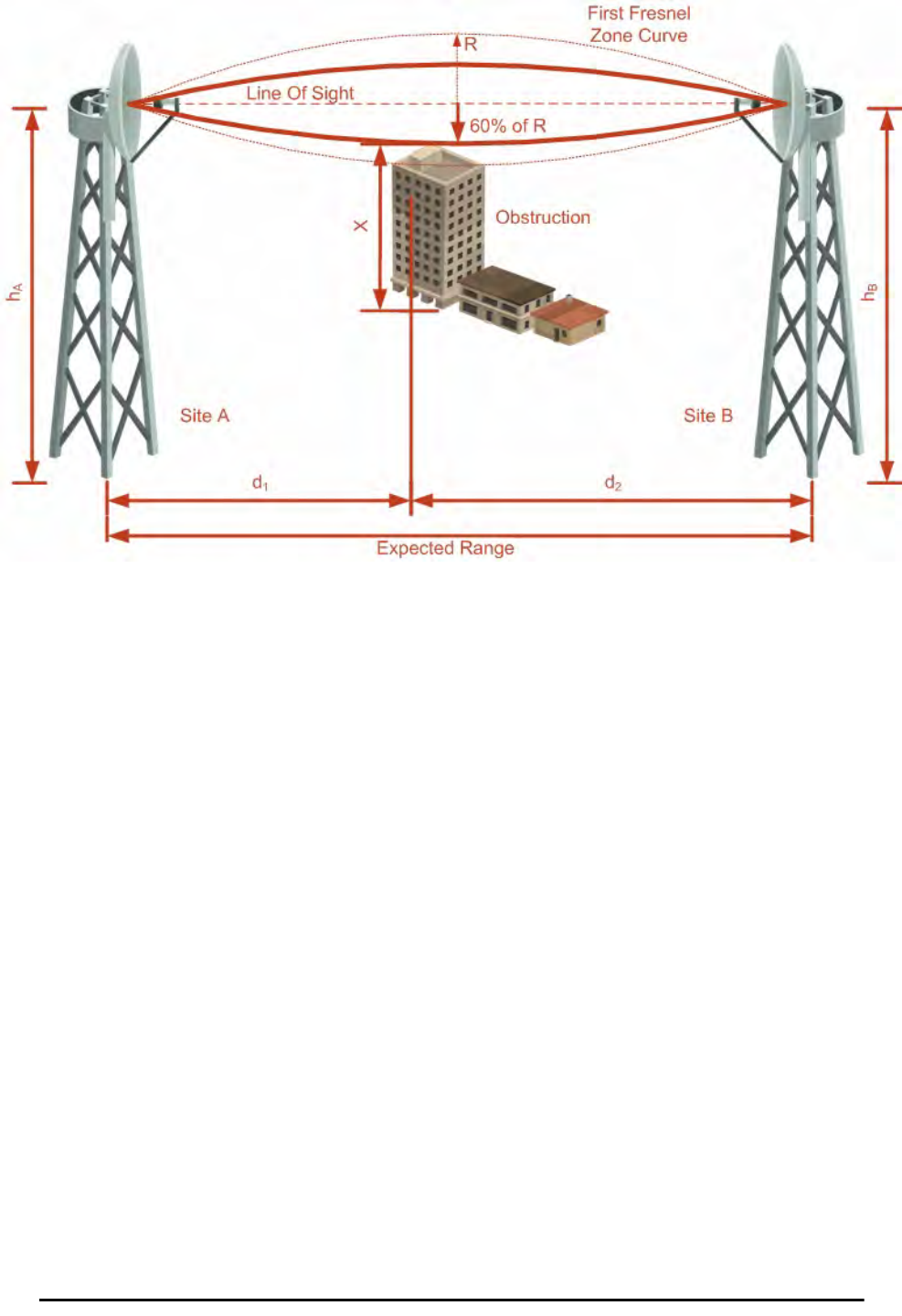
About the Fresnel Zone Chapter 21
RADWIN 2000 User Manual Release 2.5.40 21-4
Figure 21-1: Fresnel zone
Fresnel loss is the path loss occurring from multi-path reflections from reflective surfaces such
as water, and intervening obstacles such as buildings or mountain peaks within the Fresnel
zone.
Radio links should be designed to accommodate obstructions and atmospheric conditions,
weather conditions, large bodies of water, and other reflectors and absorbers of electromag-
netic energy.
The Fresnel zone provides us with a way to calculate the amount of clearance that a wireless
wave needs from an obstacle to ensure that the obstacle does not attenuate the signal.
There are infinitely many Fresnel zones located coaxially around the center of the direct
wave. The outer boundary of the first Fresnel zone is defined as the combined path length of
all paths, which are half wavelength (1/2 ) of the frequency transmitted longer than the
direct path. If the total path distance is one wavelength (1 ) longer than the direct path,
then the outer boundary is said to be two Fresnel zones. Odd number Fresnel zones reinforce
the direct wave path signal; even number Fresnel zones cancel the direct wave path signal.
The amount of the Fresnel zone clearance is determined by the wavelength of the signal, the
path length, and the distance to the obstacle. For reliability, point-to-point links are designed
to have at least 60% of the first Fresnel zone clear to avoid significant attenuation.
The concept of the Fresnel zone is shown in Figure 21-1 above. The top of the obstruction
does not extend far into the Fresnel zone, leaving 60% of the Fresnel zone clear; therefore,
the signal is not significantly attenuated.
For more about Fresnel zone, see http://en.wikipedia.org/wiki/Fresnel_zone.
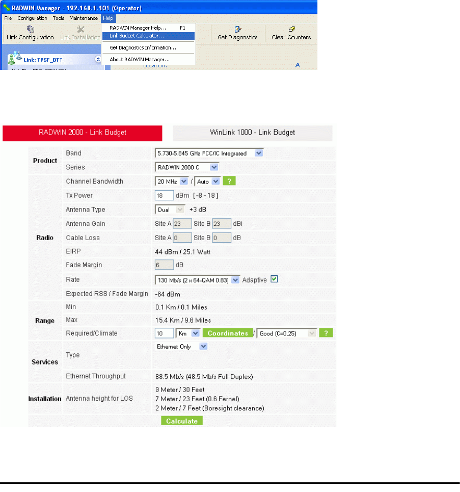
Running the Link Budget Calculator Chapter 21
RADWIN 2000 User Manual Release 2.5.40 21-5
Running the Link Budget Calculator
The Link Budget Calculator is supplied on the RADWIN Manager CD. It may be run stand-
alone from the CD or from the RADWIN Manager application.
To run the Link Budget Calculator from the CD:
1. Insert the RADWIN Manager CD into the drive on the managing computer. In the
window which opens, click the Link Budget Calculator option.
2. If the CD autorun application does not start by itself, then point your browser to
Z:\RADWIN\Setup\DATA\Link Budget Calculator.htm
where Z should be replaced with your own CD drive name.
To run the Link Budget Calculator from the RADWIN Manager:
• Choose Help | Link Budget Calculator from the main menu of the RADWIN Man-
ager as in the following figure:
Figure 21-2: Accessing the Link Budget Calculator
However invoked, your browser displays the following page:
Figure 21-3: Link Budget window
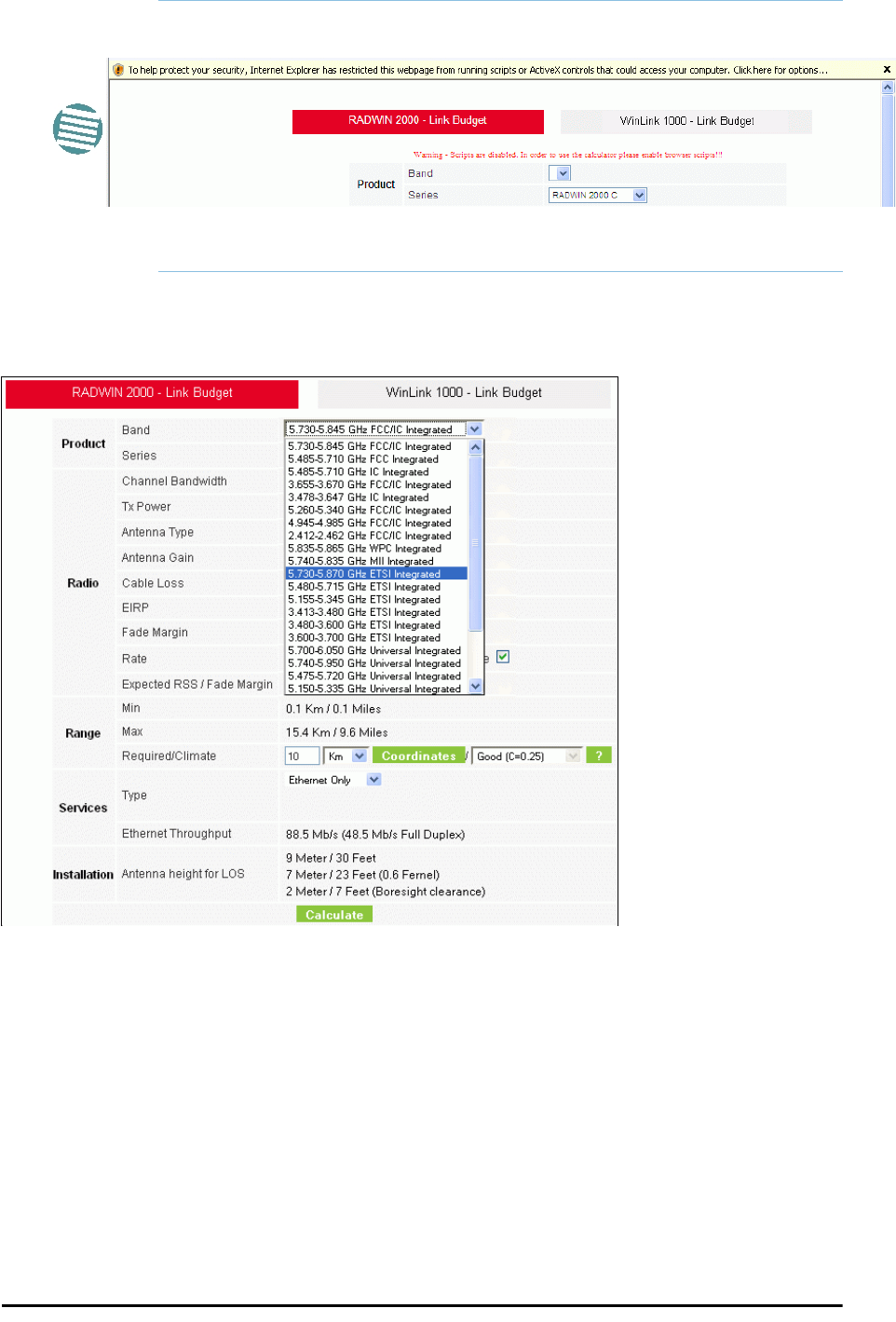
Running the Link Budget Calculator Chapter 21
RADWIN 2000 User Manual Release 2.5.40 21-6
To use the Link Budget Calculator for RADWIN 2000:
1. Choose a band from the drop-down list.
Figure 21-4: Band selector
2. Chose the relevant RADWIN 2000 series.
Note
• Microsoft Internet Explorer users may see a warning message like
this:
• Click the yellow bar and follow the instructions to allow blocked con-
tent.
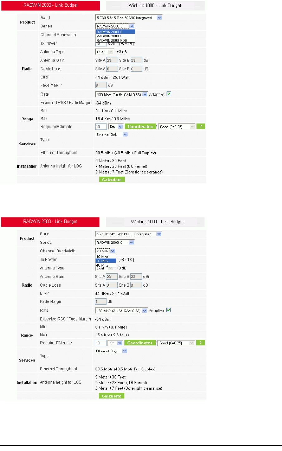
Running the Link Budget Calculator Chapter 21
RADWIN 2000 User Manual Release 2.5.40 21-7
Figure 21-5: RADWIN 2000 series selector
3. Choose the Channel Bandwidth.
Figure 21-6: RADWIN 2000 Channel Bandwidth selector
4. For a collocated link choose the RFP. Use the Help button to the right of the RFP
selection box for help:
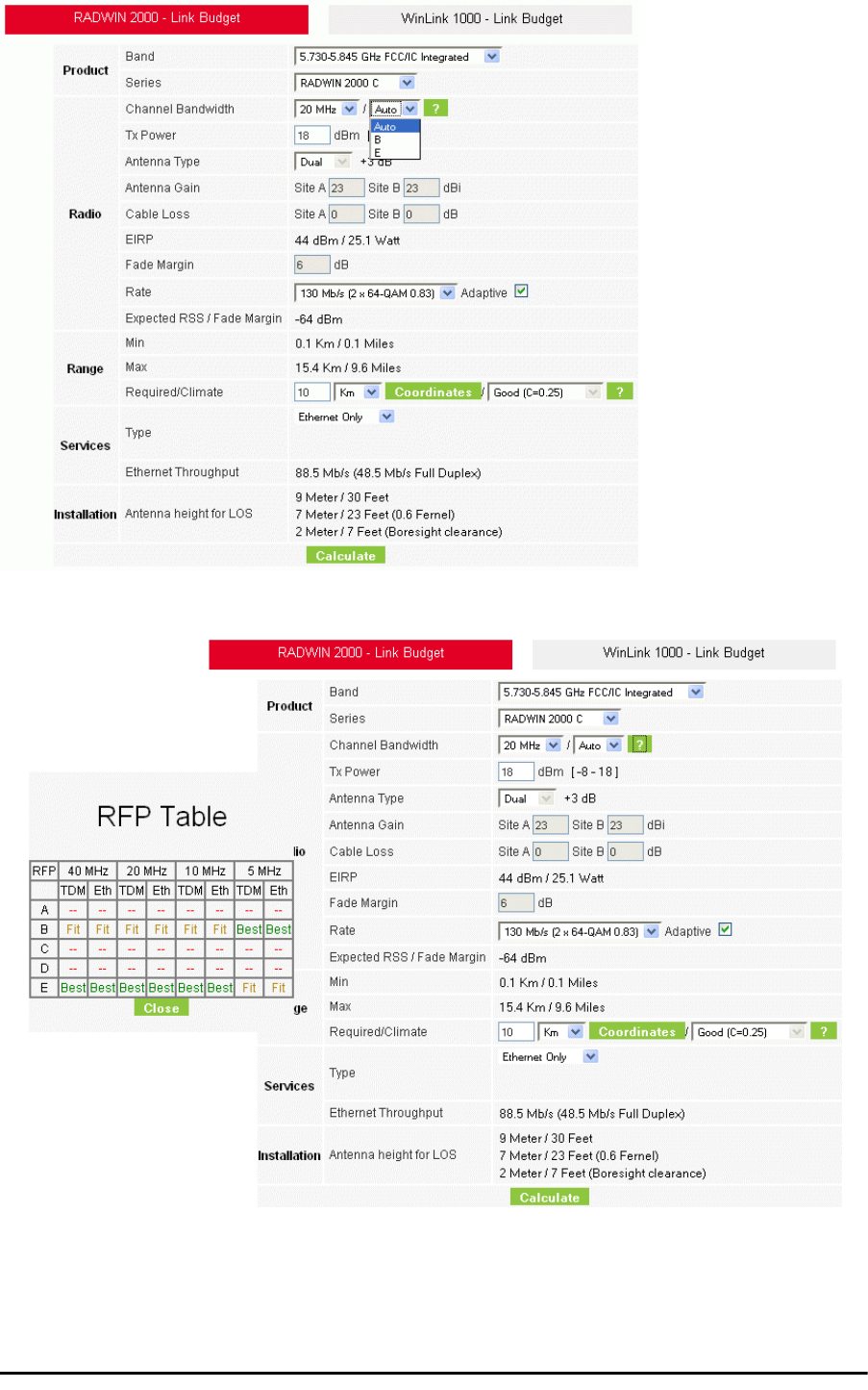
Running the Link Budget Calculator Chapter 21
RADWIN 2000 User Manual Release 2.5.40 21-8
Figure 21-7: RFP Selector
Figure 21-8: RFP Selection Guide
For collocated RADWIN 2000 products, you may only use RFP B or E.
5. Enter the radio details. Note that Rate is chosen from a drop-down list:
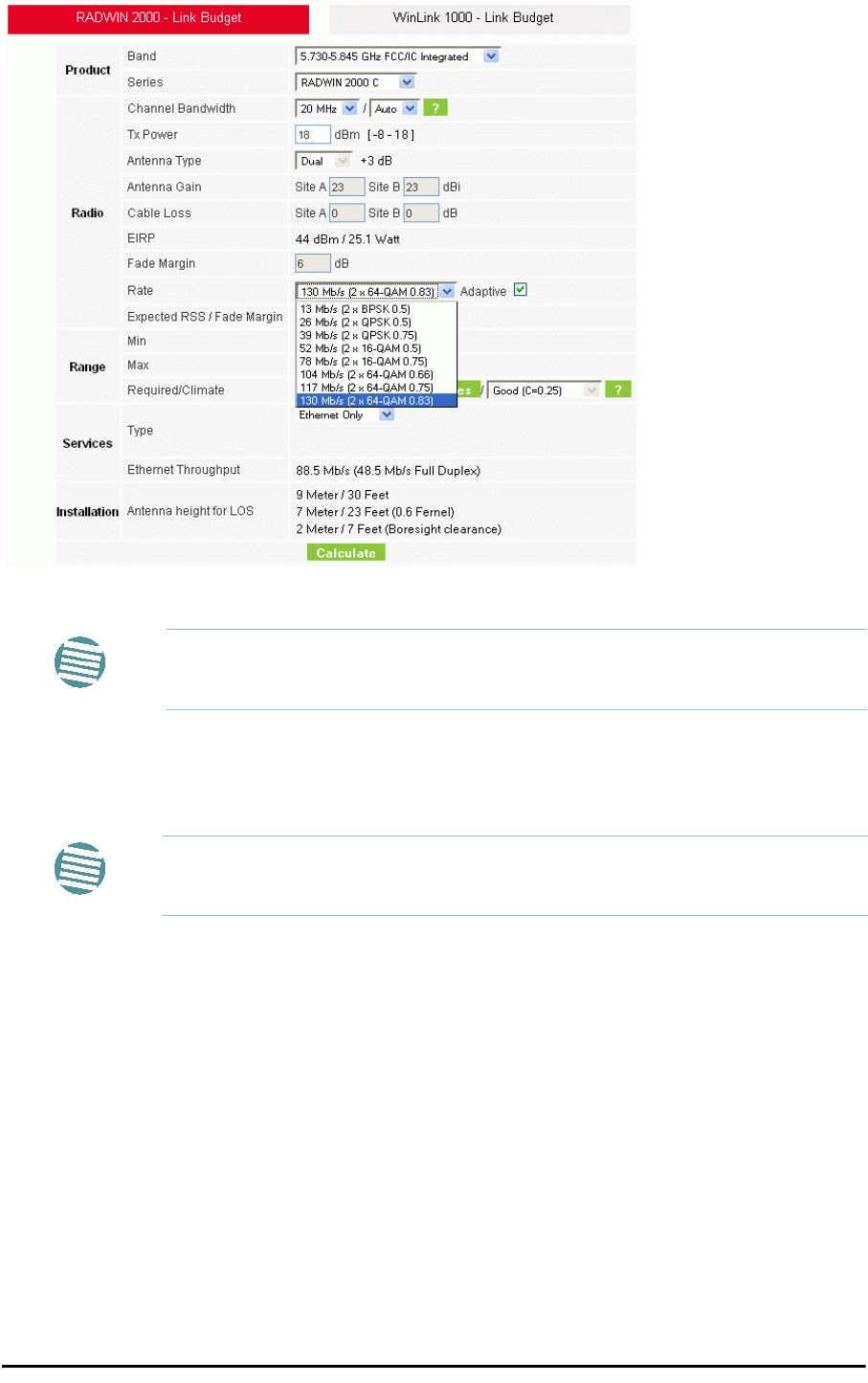
Running the Link Budget Calculator Chapter 21
RADWIN 2000 User Manual Release 2.5.40 21-9
Figure 21-9: Rate selector
The Rate shown, defines the air-interface rate in Mbps. The system operates in TDD
mode and has the overhead of the air-interface protoco.l Thus, the Ethernet actual
throughput is provided by the Ethernet Rate.
The Fade margin is the minimum required for line-o- sight (LOS) conditions. For
degraded link conditions, a larger Fade margin should be used.
The EIRP is given in dBm and Watts.
6. If the required range between the two link sites is known, you may enter it directly.
Alternatively, you may enter the latitude and longitude of each site in the link, in
which case the distance between them will be calculated and displayed.
Note
If you choose Adaptive Rate, then the Rate list is unavailable as is the
Climate factor list. Both of these quantities are calculated.
Note
For a given air-rate, Ethernet throughput will decrease with increasing range
due to propagation delay.
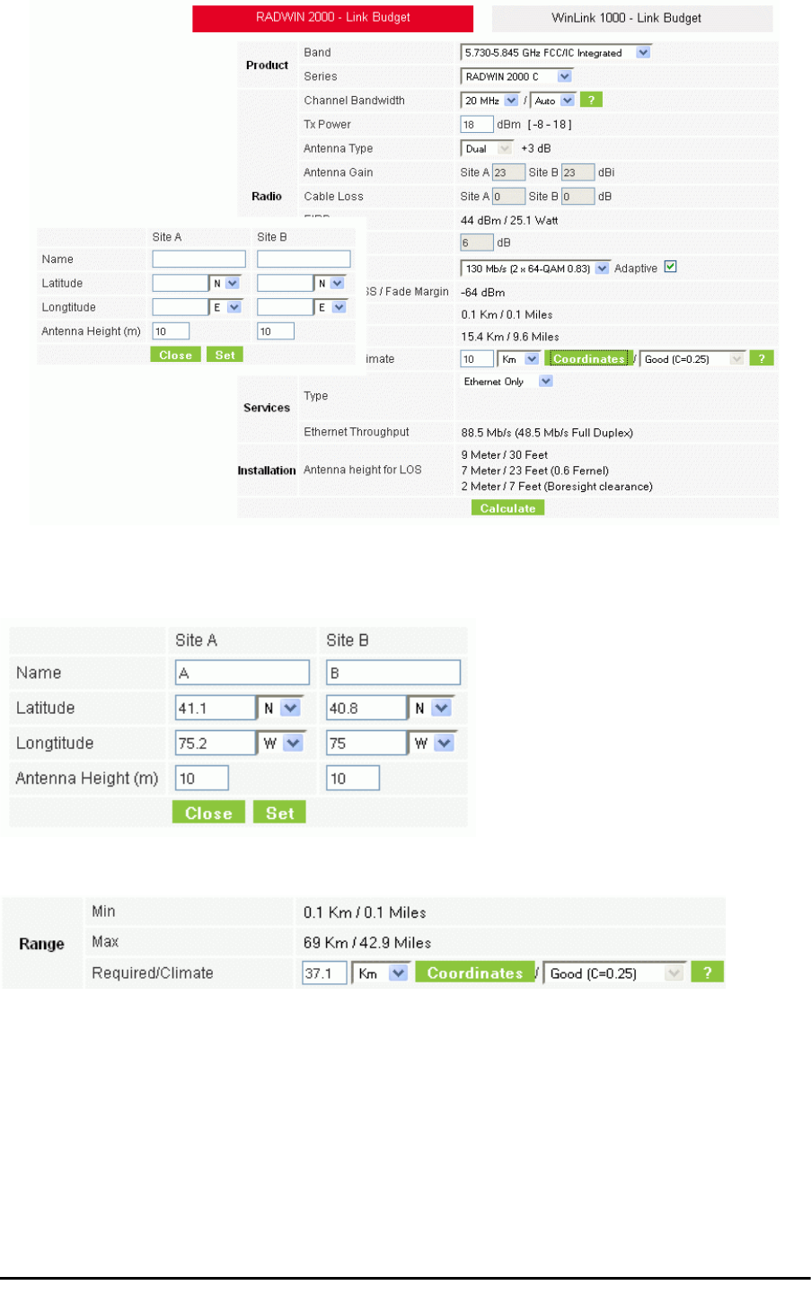
Running the Link Budget Calculator Chapter 21
RADWIN 2000 User Manual Release 2.5.40 21-10
Figure 21-10: Calculation of distance from site coordinates
For example, if you enter the following coordinates and press Set,
the range will be calculated and displayed:
If for example, we enter:
Site A: 41.1°N lat 74.2°W Long
Site B: 40.8°N lat 74.0°W Long
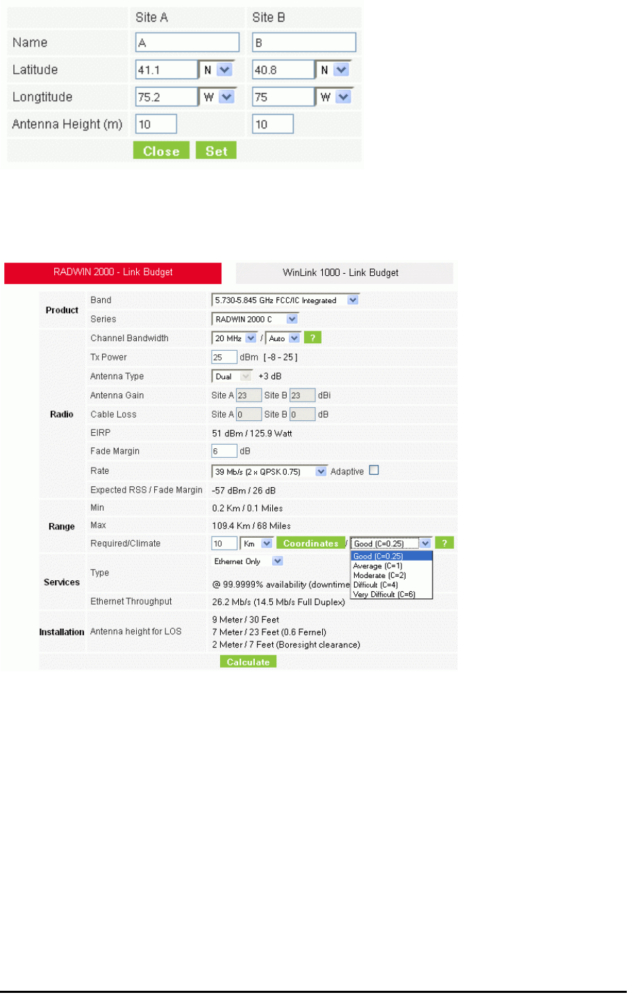
Running the Link Budget Calculator Chapter 21
RADWIN 2000 User Manual Release 2.5.40 21-11
7. Click Set. The distance and link budget is calculated.
8. Located to the right of the green Coordinates button is a drop-down list of Climactic
C Factor values. It is only available if you choose a non-adaptive rate.
Figure 21-11: Climactic C Factors
For help about what these mean, click the ? button to the right of the list in
Figure 21-11.

Running the Link Budget Calculator Chapter 21
RADWIN 2000 User Manual Release 2.5.40 21-12
Figure 21-12: Climactic C Factor description
In Figure 21-13 we display a map of the world showing C Factor contours:
Figure 21-13: World map showing C Factor contours

Running the Link Budget Calculator Chapter 21
RADWIN 2000 User Manual Release 2.5.40 21-13
9. Click Calculate to obtain the required performance estimate.
Figure 21-14: LBC - Results section
The Expected Performance parameters are calculated and displayed:
•Expected RSS - the expected RSS that the RADWIN Manager shows when the RAD-
WIN 2000 ODUs are optimally aligned
•Services Type - max number of T1 or E1 trunks if “Max Trunks” is selected
•Ethernet Rate - maximum throughput available for the chosen parameter combina-
tion
•Antenna height for LOS – the minimum antenna height required for line-of-sight
operation. It is the sum of the height required for boresight clearance due to the
earth’s curvature plus the height required to clear the Fresnel zone
If the expected performance is not suitable for your application, try different parameters and
repeat the calculation.
Note
Placing the cursor in any other calculated field will also update the
calculated results.

RADWIN 2000 User Manual Release 2.5.40 22-1
Chapter 22
Quick Install Mode
Why this is Needed
It may be required to temporarily suspend service traffic over a link without losing the link
connection. The simplest way to do this is to place the link in Installation mode but without
changing any configured parameters. Quick Install Mode is a “one click” method for doing
this. The method is completely generic, working identically for both WinLink 1000 and RAD-
WIN 2000 products.
Enabling Quick Install
By default, this feature is disabled.
To enable Quick Install mode:
1. Log on to the RADWIN Manager, navigate to Tools | Preferences and click the
Advanced tab:
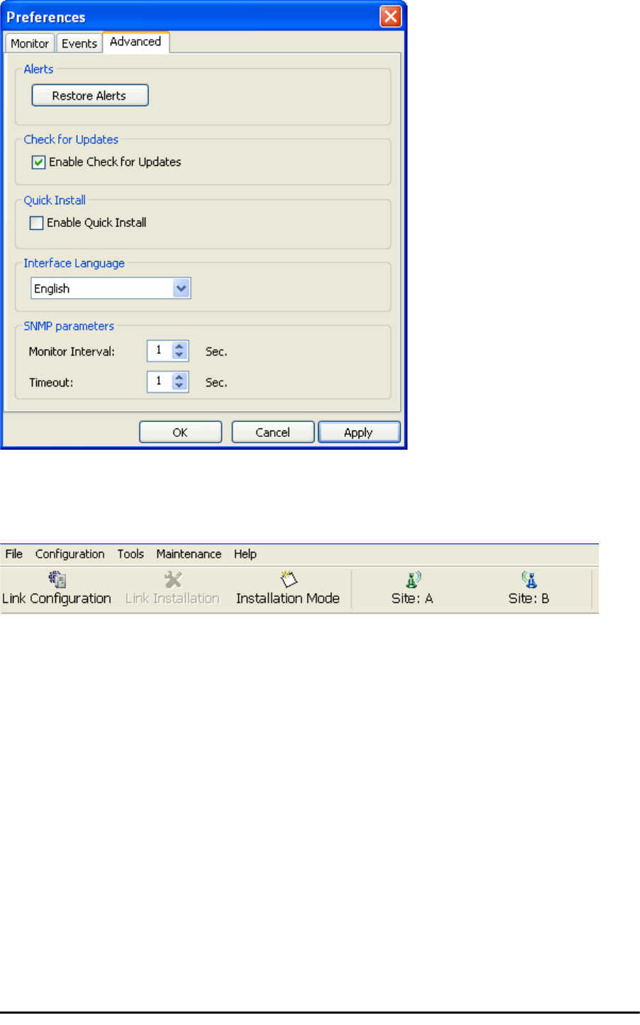
Using Quick Install Chapter 22
RADWIN 2000 User Manual Release 2.5.40 22-2
Figure 22-1: Preferences: Quick Install
2. Check the Enable Quick Install box and then OK. A new button is added to the
main window toolbar:
Figure 22-2: New Install Mode button for Quick Install mode
Quick Install mode may be disabled by unchecking the Enable Quick Install box.
Using Quick Install
To suspend service traffic and enter Installation mode:
1. Click the Install mode button. You are offered a confirmatory message:
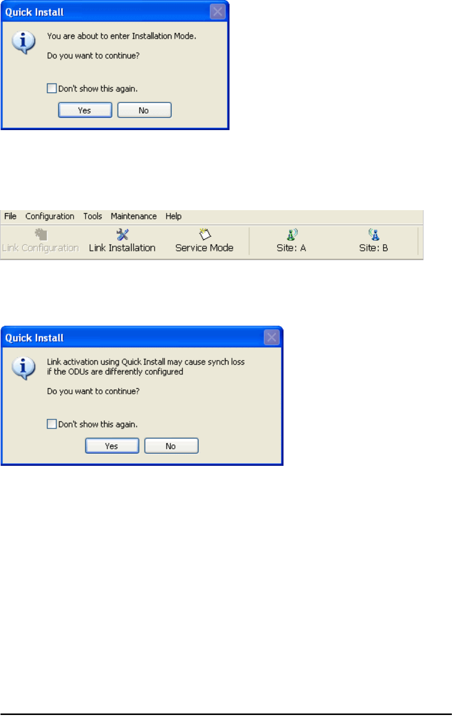
Using Quick Install Chapter 22
RADWIN 2000 User Manual Release 2.5.40 22-3
Figure 22-3: Change to Installation Mode cautionary message
2. Click Yes to continue. The link goes into Installation mode. The main window looks
the same as if you had entered Installation mode in the usual way through one of
the Site windows with the exception of the toolbar:
Figure 22-4: Service Mode button to resume link service traffic
3. When you are ready to resume normal service traffic, click the Service Mode but-
ton. The following cautionary message is displayed:
Figure 22-5: Resumption of services cautionary message
Using Quick Install Chapter 22
RADWIN 2000 User Manual Release 2.5.40 22-4
4. Click Yes to continue. The link will resume normal services with your last set config-
uration parameters provides that you did not change link parameters in a a way
leading to sync loss.
Note
It is also possible to change parameters in a way leading to service
degradation. For example mis-configuring the number of antennas or
transmission parameters at one side of the link may allow service to
resume, but in a degraded fashion.
You may only enter Quick Install mode from a configured link. If you set
both sites back to factory settings and chose Quick Install, you will not be
able to continue:

RADWIN 2000
Broadband Wireless Transmission System
USER MANUAL
RELEASE 2.5.40
Part 5: Product Dependent
Features
UM 2000-2540/02.11
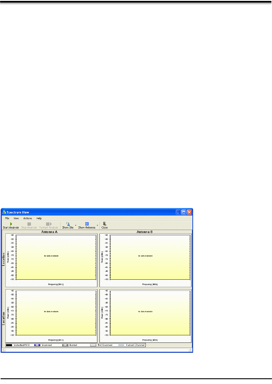
RADWIN 2000 User Manual Release 2.5.30 23-1
Chapter 23
Spectrum View
What is Spectrum View?
The RADWIN Manager Spectrum View utility is an RF survey tool designed to support the link
installation prior to full link service activation. The tool provides comprehensive and clear
spectral measurement information enabling easier, faster and better quality installations.
You can view real-time spectrum information, save the spectral information and view
retrieved spectral information from historic spectrum scans.
RADWIN’s spectrum measurement and estimation algorithms are designed to show accurate
information while accommodating with variations in frequency, temperature and interference
power while overcoming anomalies that tend to occur in high interference environments.
Running Spectrum View in Installation Mode
To launch Spectrum View, go to the RADWIN Manager main window menu and click Tools |
Spectrum View.
Figure 23-1: Starting the analysis
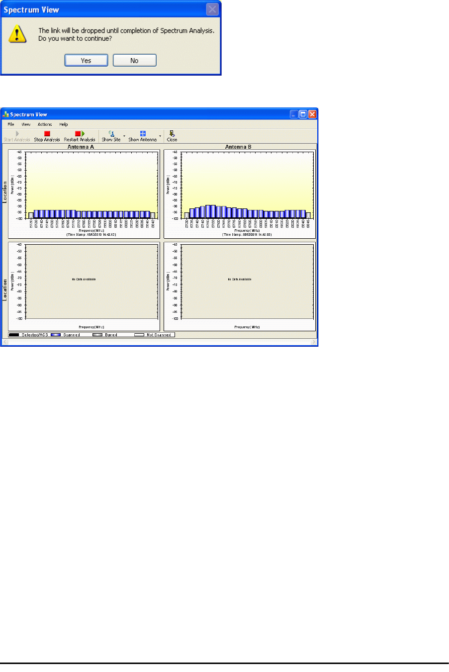
Running Spectrum View in Installation Mode Chapter 23
RADWIN 2000 User Manual Release 2.5.30 23-2
To obtain a spectrum analysis:
1. Click Start Analysis. You are asked for confirmation:
2. Click Yes. After a few moments, the first results for the managing site appear:
Figure 23-2: Site A (managing site) done
The over-the-air site takes a little longer:

Running Spectrum View in Installation Mode Chapter 23
RADWIN 2000 User Manual Release 2.5.30 23-3
Figure 23-3: Site B (over- the-air site) done, showing current channel
The analysis complete when the Start Analysis button reverts to green. It never runs
for longer than ten minutes and you may stop it any time by clicking the red Stop
Analysis button.
The results for the over-the-air site are displayed after the link is re-established
regardless whether the analysis completes by itself or is stopped.
Current channel
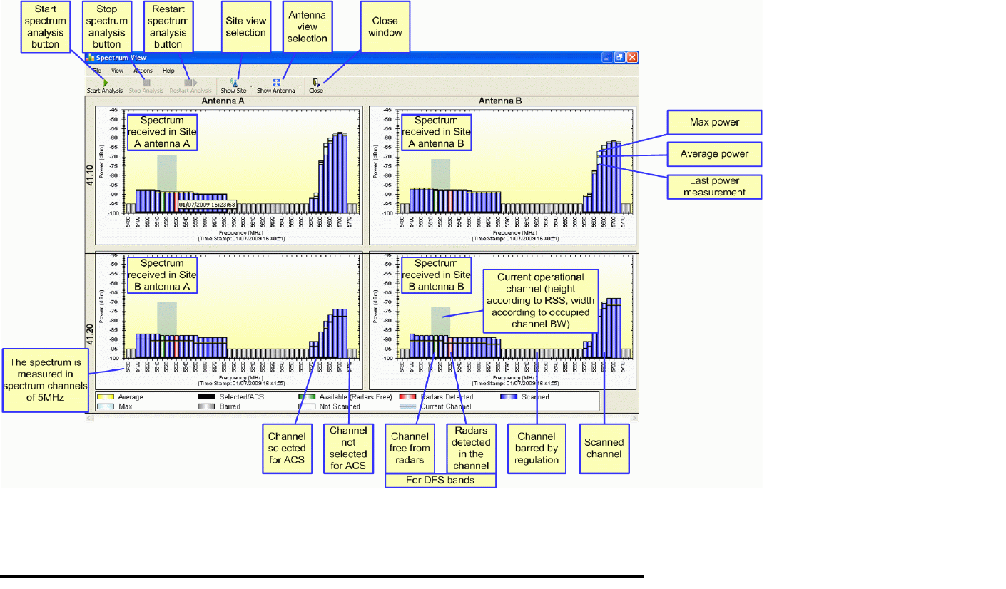
Understanding the Spectrum View Display Chapter 23
RADWIN 2000 User Manual Release 2.5.30 23-4
Understanding the Spectrum View Display
Information Displayed
Figure 23-4 shows an annotated display taken from a live link.
Figure 23-4: RADWIN 2000 Spectrum View - annotated display
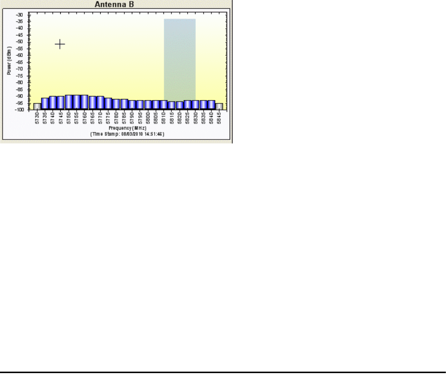
Changing the Display Chapter 23
RADWIN 2000 User Manual Release 2.5.30 23-5
From Figure 23-4 above, you can see that the Spectrum View provides clear information
including:
• Spectral measurement for each of the 4 receivers that make a RADWIN 2000 link (two
sites x two antennas per site)
• Spectral power measurements in 5MHz channel granularity
• Current, average and maximum power per channel
• Indication of
• channels free from radars
• channels with radars detected
• barred channels (for DFS bands)
• Indication of scanned and un-scanned channels
• Indication of channels selected for ACS
• Notation of the current operational channel of the RADWIN 2000 link
• Time stamp of the last spectrum scan
• Further, it supports zoom capability, selective view of antennas and sites constituting
the link and selectable detail level
Changing the Display
Moving the mouse anywhere over one the display areas changes it to a cross hair. The mouse
may then be used to select an area for zooming, or to enable a right-click System menu.
Figure 23-5: Mouse pointer active for zooming
Selecting a rectangle and clicking will zoom the channels below it to full panel width:
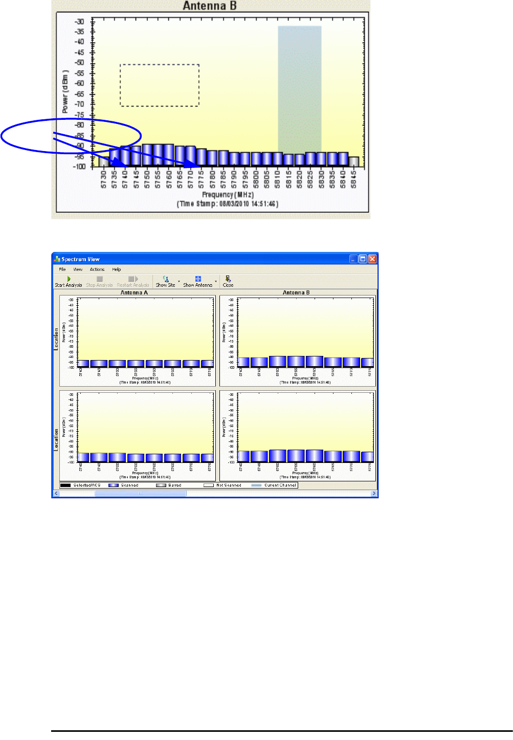
Changing the Display Chapter 23
RADWIN 2000 User Manual Release 2.5.30 23-6
Figure 23-6: Selecting an area of interest to zoom with the right mouse button down
Figure 23-7: Requested section zoomed
The zoom can be reversed using the System menu obtained by right-clicking any of the Spec-
trum View display panels. It also offers display variations such as maximum, average and cur-
rent power per channel.
Zoomed frequencies
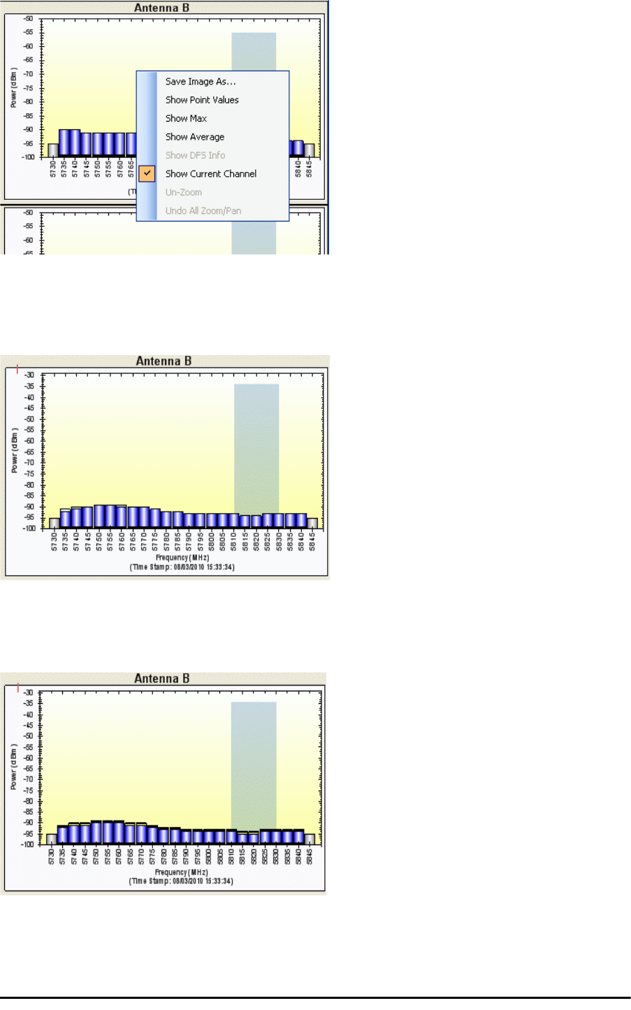
Changing the Display Chapter 23
RADWIN 2000 User Manual Release 2.5.30 23-7
Figure 23-8: Spectrum View System menu
Here are two examples:
If you click Show Max, each panel will show the peak values recorded during the analysis:
Figure 23-9: Effect of setting Show Max
If you click Show Average, each panel will show the average values recorded during the
analysis:
Figure 23-10: Effect of setting Show Average
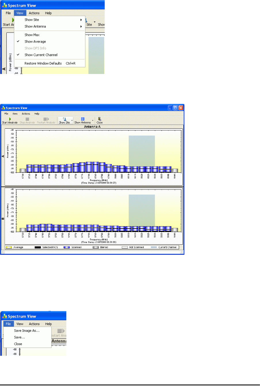
Restricting the Panels to be Displayed Chapter 23
RADWIN 2000 User Manual Release 2.5.30 23-8
Restricting the Panels to be Displayed
Click View for further viewing options:
Figure 23-11: Further viewing options
If for example you want Antenna A only, the resulting display will look like this:
Figure 23-12: Antenna A selected
Saving a Spectrum Analysis
Your analysis can be saved in a CSV (comma separated values) text file. Use the Files menu
item in the usual way:

Saving a Spectrum Analysis Chapter 23
RADWIN 2000 User Manual Release 2.5.30 23-9
The Spectrum View information is logged as part of the Diagnostics Information to improve link and system diagnostics and remote support. It
can be retrieved from the RADWIN Manager menu using Help |Get Diagnostic Information.
Here is extract of a saved Spectrum View:
Spectrum View - Site: A
Frequencies Scanned,Last Scan Timestamp,Last NF-AntennaA,Last NF-AntennaB,Average NF-AntennaA,Average NF-Anten-
naB,Max NF-AntennaA,Max NF-AntennaB
5735,True,30/11/2009 08:20:52,-89,-90,-90,-91,-89,-90,
5740,True,30/11/2009 08:20:52,-89,-90,-90,-91,-89,-90,
5745,True,30/11/2009 08:20:52,-89,-90,-90,-91,-89,-90,
...
5830,True,30/11/2009 08:20:52,-92,-94,-93,-94,-92,-93,
5835,True,30/11/2009 08:20:52,-92,-94,-93,-95,-92,-94,
5840,True,30/11/2009 08:20:52,-92,-94,-93,-95,-92,-94,
Rx Power - AntennaA: -55
Rx Power - AntennaB: -55
Spectrum View - Site: B
Frequency,Is Scanned,Last Scan Timestamp,Last NF-AntennaA,Last NF-AntennaB,Average NF-AntennaA,Average NF-Anten-
naB,Max NF-AntennaA,Max NF-AntennaB
5735,True,30/11/2009 08:20:53,-91,-90,-92,-91,-91,-90,
5740,True,30/11/2009 08:20:53,-90,-89,-91,-90,-90,-89,
5745,True,30/11/2009 08:20:53,-90,-89,-91,-90,-90,-89,
...
5830,True,30/11/2009 08:20:53,-93,-94,-94,-94,-93,-93,
5835,True,30/11/2009 08:20:53,-93,-94,-94,-95,-93,-94,
5840,True,30/11/2009 08:20:53,-93,-94,-94,-95,-93,-94,
Rx Power - AntennaA: -57
Rx Power - AntennaB: -55
The column headings are wrapped around. The table values in dBm, are noise-floor (NF) relative.
The CSV file imports easily into most spreadsheet programs. Here is a MS Excel import:
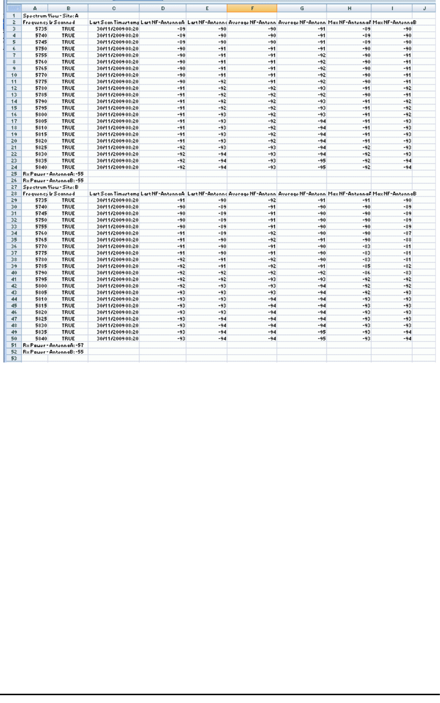
Management Integration Chapter 23
RADWIN 2000 User Manual Release 2.5.30 23-10
Figure 23-13: Spectrum View CSV file imported into MS Excel
Management Integration
Spectrum view information is supported in RADWIN’s MIB and can be used by external Net-
work Management applications.

RADWIN 2000 User Manual Release 2.5.30 24-1
Chapter 24
BRS/EBS Considerations
What is BRS/EBS
The Broadband Radio Service (BRS), formerly known as the Multipoint Distribution Service
(MDS)/Multichannel Multipoint Distribution Service (MMDS), is a US FCC regulated commer-
cial service. The relevant FCC rule is 47CFR part 27.
In the past, it was generally used for the transmission of data and video programming to sub-
scribers using high-powered wireless cable systems. However, over the years, it has evolved
to include digital two-way systems capable of providing high-speed, high-capacity broadband
service, including two-way Internet service via cellularized communication systems. Such ser-
vices provide consumers integrated access to voice, high-speed data, video-on-demand, and
interactive delivery services from a wireless device.
For further details see:
http://wireless.fcc.gov/services/index.htm?job=service_home&id=ebs_brs
This link (part of the FCC site) contains the Technical Rules covering matters such as:
• Operational scope
• Geographic service area
• Antenna registration
BRS/EBS Bands
The BRS/EBS band (post-transition) is illustrated in Figure 24-1 below and in more detail in
the three tables following.
Observe that the BRS/EBS spectrum is divided into small channels, mainly of 5.5 and 6 MHz.
There are two small ranges of 0.333 MHz channels as well.
BRS/EBS user may lease blocks of up to four contiguous channels to achieve their required
channel bandwidth. These are often referred to as single, double, triple or quad bands.
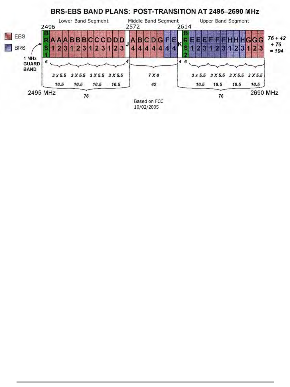
Post transition frequency assignments according to FCC CFR47 PART 27 section
RADWIN 2000 User Manual Release 2.5.30 24-2
Post transition frequency assignments according to FCC CFR47
PART 27 section 27.5:2009
Figure 24-1: BRS/EBS Bands Schematic
The tables below provide a detailed view of the spectrum from 2.495 GHz to 2.690 GHz
The sections marked J and K are not detailed. since they are not supported by RADWIN prod-
ucts.

Post transition frequency assignments according to FCC CFR47 PART 27 section 27.5:2009 Chapter 24
RADWIN 2000 User Manual Release 2.5.30 24-3
(‡) Using a triple channel would be wasteful
over a single link.
Table 24-1: BRS/EBS Lower Band Segment
(LBS)
Channel type Channel
Tag CBW
MHz
Band
MHz
From To
BRS Guard 1 6 2496.0 2502.0
EBS
A1
5.5
2502.0 2507.5
A2 2507.5 2513.0
A3 2513.0 2518.5
B1 2518.5 2524.0
B2 2524.0 2529.5
B3 2529.5 2535.0
C1 2535.0 2540.5
C2 2540.5 2546.0
C3 2546.0 2551.5
D1 2551.5 2557.0
D2 2557.0 2562.5
D3 2562.5 2568.0
EBS
(not supported
by RADWIN)
JA1
0.33333 2568.0 2572.0
JA2
JA3
JB1
JB2
JB3
JC1
JC2
JC3
JD1
JD2
JD3
Table 24-2: BRS/EBS Middle Band Segment
(MBS)
Channel type Channel
Tag CBW
MHz
Band
MHz
From To
EBS
A4
6
2572 2578
B4 2578 2584
C4 2584 2590
D4 2590 2596
G4 2596 2602
BRS/EBS F4 2602 2608
E4 2608 2614
Table 24-3: BRS/EBS to RADWIN 2000 CBW
mapping and Max Tx Power
BRS/
EBS
Band
Channel
Type
Total
CBW
MHz
RADWIN 2000
CBW
MHz
Max Tx
Power
dBm
LBS & HBS
5.5 MHz/slice
Single 5.5 5 22
Double 11.0 10 23
Triple 16.5 Don’t use (‡)
Quad 22.0 20 24
MBS
6 MHz / slice
Single 6 5 22
Double 12 10 23
Triple 18 Don’t use (‡)
Quad 24 20 24
Table 24-4: BRS/EBS Upper Band Segment
(UBS)
Channel type Channel
Tag CBW
MHz
Band
MHz
From To
EBS/EBS, mixed
(not supported
by RADWIN)
KH1
0.33333 2614.0 2618.0
KH2
KH3
KG1
KG2
KG3
KF1
KF2
KF3
KE1
KE2
KE3
BRS Guard 2 6 2618 2624
BRS/EBS
E1
5.5
2624.0 2629.5
E2 2629.5 2635.0
E3 2635.0 2640.5
F1 2640.5 2646.0
F2 2646.0 2651.5
F3 2651.5 2657.0
BRS
H1 2657.0 2662.5
H2 2662.5 2668.0
H3 2668.0 2673.5
EBS
G1 2673.5 2679.0
G2 2679.0 2684.5
G3 2684.5 2690.0

Setting up a BRS/EBS link using RADWIN 2000 2.5GHz Band Chapter 24
RADWIN 2000 User Manual Release 2.5.30 24-4
Setting up a BRS/EBS link using RADWIN 2000 2.5GHz
Band
The key issue in setting up a RADWIN 2000 2.5GHz Band BRS link is the choice of an appro-
priate channel bandwidth (CBW), which in turn depends on whether you are leasing a single,
double, triple or quad band set.
RADWIN BRS radios operate with channel bandwidths selectable from 5, 10 and 20 MHz.
Choose your channel bandwidth in accordance with Table 24-3.
Note
RADWIN does not support the bands labeled J and K in Figure 24-1.

RADWIN 2000 User Manual Release 2.5.40 25-1
Chapter 25
Quality of Service
Availability
The Quality of Service (QoS) feature is available for links using RADWIN 2000 C radios. If you
already have this model, you can access the feature by carrying out a Software Upgrade to
the 2.5.40 release.
To use the facility you must be familiar with the use of VLAN (802.1p) or Diffserv.
QoS - Overview
QoS is a technique for prioritization of network traffic packets during congestion.
RADWIN 2000 C links support two classification criteria, VLAN based or Diffserv based. You
may chose which of them to use.
Based upon the classification criterion chosen, received packets will be mapped into one of
four quality groups: Real time, Near real time, Controlled load and Best effort.
You may partition the total link capacity across the four Quality queues. The default weights
as percentages are shown in Table 25-1.
Table 25-1: Default priorities an d allocation by VLAN ID and Diffserv
Quality queue Priority REDAT %
Diffserv VLAN
Real time 48-63 6-7 15
Near real time (responsive
applications) 32-47 4-5 20
Controlled load 16-31 2-3 25
Best effort 0-15 0-1 40
Note
For REDAT (Remaining Ethernet Data - Ethernet throughput) measurement
- see Throughput Checking. REDAT measures remaining Ethernet
throughput after reduction of bandwidth used by TDM channels. Use the
Link Budget Calculator to see how much remaining bandwidth is available
for Ethernet.
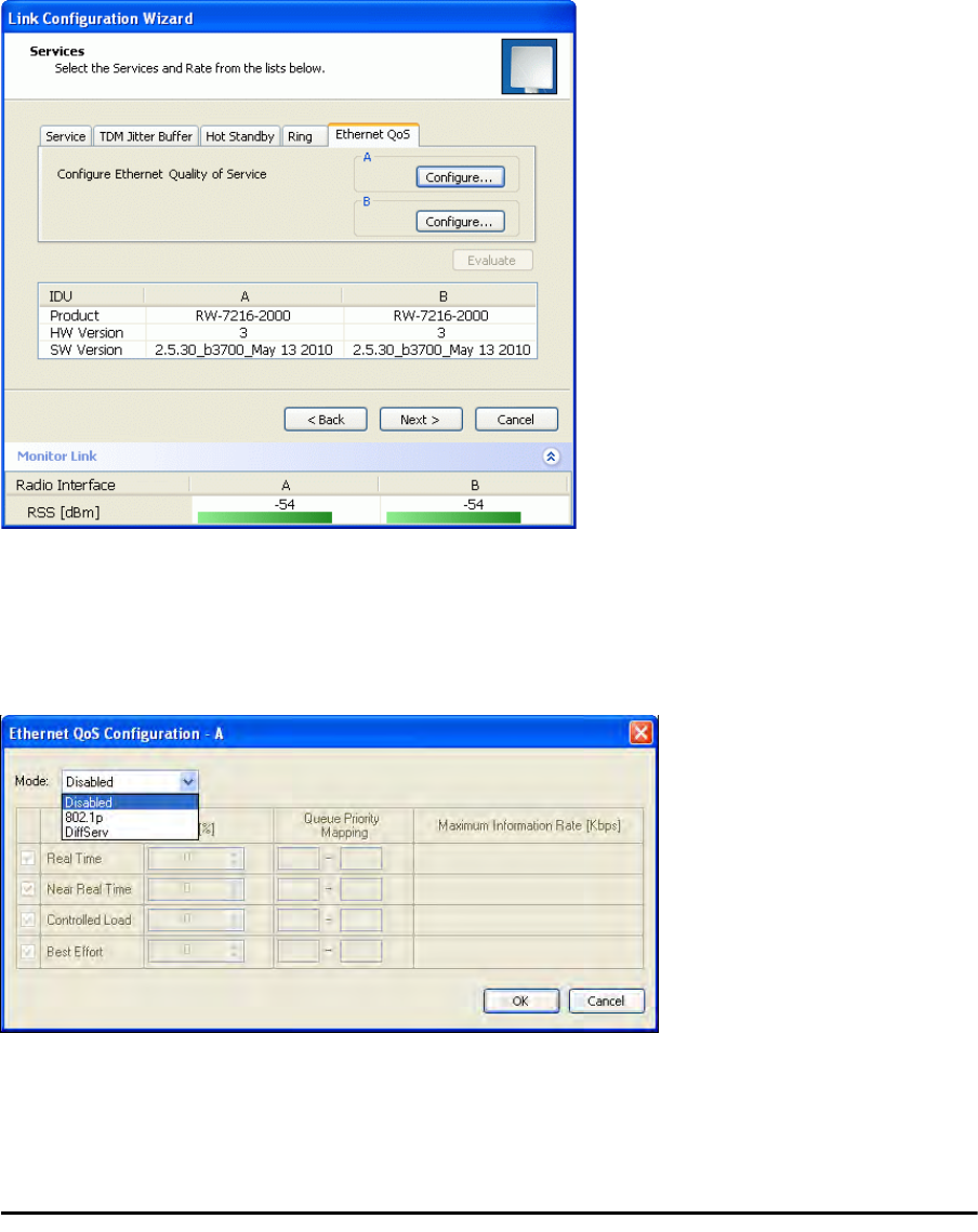
Setting up QoS Chapter 25
RADWIN 2000 User Manual Release 2.5.40 25-2
Further, you may also limit the maximum information rate (MIR) for each queue per site.
Setting up QoS
You may set up QoS from either the Installation or Configuration wizards. Before doing so, set
up for VLAN (Chapter 14) or Diffserv, depending on which you intend to use.
To define QoS settings for a link:
1. Using either the Installation or Configuration wizards, navigate to the Services win-
dow and chose the QoS tab.
Figure 25-1: Services window with QoS selected
Although QoS is a link-oriented feature, each site may have its own separate param-
eters.
2. Click the Configure button for a site.
Figure 25-2: Ethernet QoS Configuration - Mode selection
3. Choose the required mode - 802.1p (VLAN) or Diffserv.
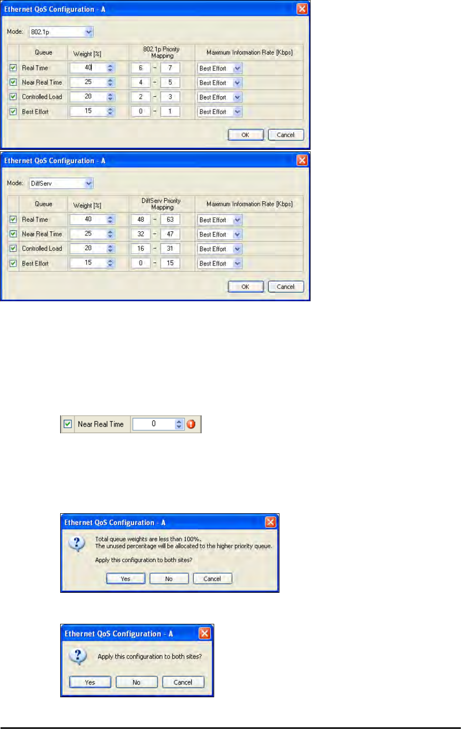
Setting up QoS Chapter 25
RADWIN 2000 User Manual Release 2.5.40 25-3
Figure 25-3: Top: VLAN allocation. Bottom: Diffserv allocation
4. The entry fields in both cases are self evident. Upon clicking OK,
• If you over-book the Weight column, the last entered field will be reduced so
that the total is 100%.
• No weight field may be left zero. If you do, you will not be able to proceed until it
is set to something:
.
This reflects the implementation policy under which no checked queue may be
completely starved. If you really do not want to use a queue under congestion,
uncheck it.
• If you are under-booked, you will receive this notice:
• In any event, you may automatically apply the same settings to both link sites:

Disabling QoS Chapter 25
RADWIN 2000 User Manual Release 2.5.40 25-4
5. Priorities: You are completely responsible for the completeness and consistency of
your VLAN or Diffserv priorities.
6. Choose a Maximum Information Rate for each queue:
Figure 25-4: MIR choice - per queue
If you previously used Site | Ethernet | Maximum Information Rate (Chapter
8) to globally limit the site, then your choice in Figure 25-4 will also be limited.l
7. Click OK on the exit dialog to accept the settings. If you did not use these settings for
the opposite site, you should configure it now.
8. Complete the wizard in the usual way.
Disabling QoS
In the dialog of Figure 25-2, choose the Disabled mode. The two sites may be enabled or
disabled independently.

RADWIN 2000
Broadband Wireless Transmission System
USER MANUAL
RELEASE 2.5.40
Part 6: Product Reference
UM 2000-2540/02.11

RADWIN 2000 User Manual Release 2.5.40 A-1
Appendix A
Technical Specifications
Scope of these Specifications
This appendix contains technical specifications for the major link components appearing in
this User Manual. They are correct at the date of publication, but are intended for general
background only. The latest authoritative and most up to date technical specifications are
available as Data Sheets obtainable from RADWIN Customer Service.
In any event, RADWIN reserves the right to change these specifications without notice.
ODU
Capacity
• RADWIN 2000 C: Up to 16 E1/T1 services and up to 100 Mbps capacity
(net throughput, full duplex)
• RADWIN 2000 X: Up to 3 E1 or 4 T1 services up to 10Mbps capacity (net
throughput , full duplex)
• RADWIN 2000 L: Up to 50 Mbps capacity (net throughput, full duplex)
• RADWIN 2000 PDH: Up to 16 E1/T1 services and up to 10 Mbps capacity
(net throughput, full duplex. Requires an IDU-C or E, no PoE support
Range Up to 120 km / 75 miles
Radio Modulation 2x2 MIMO-OFDM (BPSK/QPSK/16QAM/64QAM)
Adaptive Modulation & Coding Supported
Automatic Channel Selection Supported
Diversity Supported
Spectrum View Supported
Duplex Technology TDD
Error Correction FEC k = 1/2, 2/3, 3/4, 5/6
Rate – Dual Antenna [Mbps] 13 26 39 52 78 104 117 130
Rate – Single Antenna [Mbps] 6.5 13 19.5 26 39 52 58.5 65
Modulation BPSK QPSK 16QAM 64QAM
FEC [k=] 1/2 1/2 3/4 1/2 3/4 2/3 3/4 5/6
Max Tx Power [dBm] for 4.8 – 6 GHz 25 24 21 19 18
Max Tx Power [dBm] for 2.4 GHz 26 25 24 24 21 20
Max Tx Power [dBm] for 2.5 GHz (BRS) See Table 24-3

ODU Appendix A
RADWIN 2000 User Manual Release 2.5.40 A-2
(‡)Not available for X series ODUs.
(†)Split into three sub-bands. See page 20-9.
(*) Split into many sub-bands. There are also Tx Power limitations. See Chapter 24, and in
particular, tables 24-1 to 24-4.
Sensitivity (dBm) @BER <10e-11
(20MHz) -88 -86 -83 -81 -77 -72 -70 -67
Encryption AES 128
Band Occupied
Frequency range
[GHz] Compliance Channel Bandwidth
5 MHz 10 MHz 20 MHz 40 MHz
FCC/IC 5.8 5.725 - 5.850 FCC 47CFR, Part 15, Subpart C and IC RSS-210 No Yes Yes Yes
FCC 5.4 5.480 - 5.715 FCC 47CFR, Part 15, Subpart E No Yes Yes Yes
IC 5.4 5.480 – 5.590
5.660 – 5.715 IC RSS-210 No Yes Yes Yes
FCC/IC 5.3 5.260 - 5.340 FCC 47CFR, Part 15, Subpart E and IC RSS-210 No Yes Yes Yes
FCC/IC 4.9 4.940 - 4.990 FCC 47CFR, Part 90, Subpart Y and IC RSS-111 No Yes Yes No
FCC/IC 2.4 2.402 - 2.472 FCC 47CFR, Part 15, Subpart C and IC RSS-210 No Yes Yes No
FCC/IC 3.6(Lic) 3.650 - 3.675 FCC Part 90 Subpart Z and IC RSS-197 (Restricted) Yes Yes(‡) Yes(‡) No
FCC 2.5(*) 2.495 2.690 FCC CFR47 PART 27 section 27.5:2009 (BRS/EBS) Yes Yes Yes No
IC 3.4 (Lic) 3.475 – 3.650 IC RSS-192 Yes Yes(‡) Yes(‡) No
WPC India 5.8 5.825 – 5.875 GSR-38 No Yes Yes Yes
MII China 5.8 5.730 – 5.845 MII China No Yes Yes Yes
ETSI 5.8 5.735 – 5.865 ETSI EN 302 502 No Yes Yes No
ETSI 5.4 5.480 – 5.715 ETSI EN 301 893 No Yes Yes Yes
ETSI 5.3 5.160 – 5.340 ETSI EN 301 893 No Yes Yes No
ETSI 3.4 (Lic)(†) 3.400 - 3.700 ETSI EN 302 326-2 Yes Yes(‡) Yes(‡) No
Universal 6.0 5.690– 6.060
N/A
No Yes Yes Yes
Universal 5.9 5.730 – 5.960 No Yes Yes Yes
Universal 5.4 5.490 – 5.710 No Yes Yes Yes
Universal 5.3 5.140 – 5.345 No Yes Yes Yes
Universal 4.9 4.890 - 5.010 No Yes Yes Yes
Universal 4.8 4.800 - 4.900 No Yes Yes Yes
Universal 2.3 2.302 - 2.379 No Yes Yes No
Universal 3.4 3.300 - 3.800 Yes Yes(‡) Yes(‡) No
ODU with Integrated Antenna 37.1/14.84(W) x 37.1/14.84(H) x 9.00/3.6(D) cm/in; 3.5 kg / 7 lbs
ODU Connectorized 18.0/7.2(W) x 27.0/10.8(H) x 5.5/2.2(D) cm/in; 1.5 kg / 3.0 lbs
Power Feeding Dual feeding, -20 to -60 VDC (AC/DC converter is available)
Power Consumption - alone 25W
Power Consumption with IDU See IDU specifications, this Appendix

IDU Appendix A
RADWIN 2000 User Manual Release 2.5.40 A-3
IDU
The following specifications are for most part, common to both IDU-C and new style IDU-E
products. Differences are pointed out in the tables.
Architecture ODU: Outdoor Unit with Integrated Antenna or Connectorized for External
Antenna
IDU: Indoor Unit for service interfaces or PoE device for Ethernet only
ODU to IDU/PoE Interface Outdoor CAT-5e cable; Maximum cable length: 100 m
Management Application (per link) RADWIN Manager
Protocol SNMP and Telnet
NMS RADWIN NMS
Operating Temperatures ODU: -35°C to +60°C / -31°F to +140°F
Humidity ODU: Up to 100% non-condensing, IP67
FCC/IC (cTUVus) UL 60950-1, UL 60950-22, CAN/CSA C22.2 60950-1, CAN/CSA C22.2 60950-22
ETSI/IEC EN/IEC 60950-1, EN/IEC 60950-22
FCC 47 CFR Class B, Part15, Subpart B
ETSI EN 300 386, EN 301 489-1, EN 301 489-4
CAN/CSA CISPR 22-04 Class B
AS/NZS CISPR 22:2004 Class B
IDU-C IDU-E
Number of ports 16, 8, 4 ports or no TDM ports. 2 or no TDM port
Max ports usable by WinLink 1000 42
Max ports usable by RADWIN 2000 16 2
Type E1/T1 configurable by RADWIN Manager
Framing Unframed (transparent)
Timing Independent timing per port, Tx and Rx
Connector RJ-45
Standards Compliance ITU-T G.703, G.826
Line Code E1: HDB3 @ 2.048 Mbps, T1: B8ZS/AMI @ 1.544 Mbps
Latency Configurable 5-20 msec
Impedance E1: 120Ω, balanced, T1: 100Ω, balanced
Jitter & Wander According to ITU-T G.823, G.824

IDU Appendix A
RADWIN 2000 User Manual Release 2.5.40 A-4
Jitter Buffer Jitter Buffer configuration enabling a latency from 5msec to 16msec for
interference immunity confront
Clock Recovery Resolution 0.05ppb
Clock stability 20ppm as clock master (crucial for wander requirements of cellular operators)
Ethernet ports
Ports: 2
10/100BaseT with Auto-Negotiation (IEEE 802.3u)
Framing/Coding IEEE 802.3
Connector RJ-45
Line Impedance 100 Ω
SFP port (IDU-C only) 1 port, Type: Fast Ethernet
VLAN Support Transparent
Maximum Frame Size 2047 Bytes
Bridge Layer 2, self-learning of up to 2047 MAC addresses (IEEE 802.1Q), hub/Bridge
selectable mode
Latency 3 msec
Dry Contact Alarms 4 Inputs + 4 Outputs; Configurable by the RADWIN Manager
Monitored Hot Standby (IDU-C only) Supported
IDU-C IDU-E
Style 1U 19” Rack mounted Half 19” wall mounted or desktop
Dimensions 43.6cm(W) x 21cm(D) x 4.4cm(H) 22cm(W) x 17cm(D) x 4.4cm(H)
Weight 1.5 kg/3.3 lbs 0.5 kg/1.1 lbs
IDU-C IDU-E
Power Consumption
With WinLink 1000 ODU < 15W < 15W
With RADWIN 2000 ODU < 35W < 35W
Alone 7W 3W
Power Feeding Options Dual feeding, -20 to -60VDC Single feeding, -20 to -60VDC
Operating Temperatures 0°C - 50°C / 32°F - 122°F
Humidity 90% non-condensing
FCC/IC (cTUVus) UL 60950-1, CAN/CSA C22.2 60950-1
ETSI/IEC EN/IEC 60950-1
IDU-C IDU-E

PoE Device - Indoor, AC Appendix A
RADWIN 2000 User Manual Release 2.5.40 A-5
PoE Device - Indoor, AC
FCC CFR47 Class B, Part15, Subpart B
ETSI EN 300 386, EN 301 489-4, EN 301 489-1
CAN/CSA-CEI/IEC CISPR 22 Class B
AS/NZS CISPR 22:2006 Class B
AC Input Voltage 100-240VAC nominal, 85-265VAC max range
Input Frequency 47-63Hz
Input Current 1.5A max at 90VAC, 0.75A max at 265VAC
Output Voltage and Current 55VDC, 0-1A Range 50-58VDC
Protection
Short circuit protection
Auto recovery
Over voltage protection
Indication Green led for normal operation
Ethernet LAN interface type RJ 45, 10/100BaseT Interface (Line Impedance -100)
AC Standard socket IEC320 C14 type
ODU (PoE Port) RJ-45 connector
Case Plastic
Dimensions 16cm(W) x 6.3cm(D) x 3.33cm(H)
Weight 250g
Operating Temperatures 0°C - 40°C
Humidity 90% non-condensing
UL 60950
C-UL 60950
TUV/GS IEC/EN 60950
ESD 61000-4-2
RS 61000-4-3
EFT 61000-4-4
Surge 61000-4-5
CS 61000-4-6

PoE Device - Outdoor, DC Appendix A
RADWIN 2000 User Manual Release 2.5.40 A-6
PoE Device - Outdoor, DC
GSU
DIPS 61000-4-11
EMI FCC part 15 class B, CISPR Pub 22 class B
Input voltage range -20 to -60 VDC (single input)
Output voltage 48VDC / 0.6A
Power Consumption 0.5W (not including radio)
Protections Differential - 15KW
Common – 3KW
Ethernet LAN interface type RJ 45, 10/100BaseT Interface (Line Impedance -100)
DC input 2 pins connector
ODU (PoE Port) RJ45
Dimensions 24.5cm(H) x 13.5cm(W) x 4.0cm(D)
Weight 1.0kg/2.2lbs
Enclosure All weather cases
Operating Temperatures -35C - 60C / -31F - 140F
Humidity Up to 100% non-condensing
Standards IEC 60721-3-4 Class 4M5
IP67
FCC/IEC/ CAN/CSA 60950-1, 60950-22
ETSI EN 300 386 V1.3.2; EN 301 489-1 V1.4.1
FCC CFR47 Class B, Part15, Subpart B
CAN/CSA ICES-003:2004 Class B
AS/NZS CISPR 22:2006 class B
Architecture Outdoor Unit Connectorized for External GPS Antenna
GSU to PoE Interface Outdoor CAT-5e cable; Maximum cable length: 100 m
Dimensions 24.5cm(H) x 13.5cm(W) x 4.0cm(D)
Weight 1.0kg/2.2lbs

Antenna Characteristics Appendix A
RADWIN 2000 User Manual Release 2.5.40 A-7
Antenna Characteristics
An antenna is the radiating and receiving element from which the radio signal, in the form of
RF power, is radiated to its surroundings and vice versa. The transmission range is a function
of the antenna gain and transmitting power. These factors are limited by country regulations.
The RADWIN 2000 may be operated with an integrated antenna attached to the ODU unit, or
with an external antenna wired to the ODU via a N-type connectors. All cables and connec-
tions must be connected correctly to reduce losses. The required antenna impedance is 50Ω.
Power Feeding Power provided by PoE device
Max Power Dissipation 10Watt
Operating Temperature Range -35°C to + 60°C / -13°F to 140°F
Humidity Up to 100% non-condensing
EN/IEC Designed to meet EN/IEC 60950-1, 60950-22
FCC Designed to meet 47 CFR Class B, Part15, Subpart B
ETSI Designed to meet EN 300 386 V1.3.3; EN 301 489-4 V1.3.1; EN 301 489-1
CAN/CSA-CEI/IEC Designed to meet CISPR 22-02
AS/NZS Designed to meet CISPR22: 2006 Class B

RADWIN 2000 User Manual Release 2.5.40 B-1
Appendix B
Wiring Specifications
ODU-IDU Cable
The ODU-IDU cable is shielded/outdoor class CAT-5e, 4 twisted-pair 24 AWG terminated with
RJ-45 connectors on both ends. A cable gland on the ODU side provides hermetic sealing.
The following table shows the connector pinout:
ODU/HSS Unit Connection Pinout
Table B-1: ODU-IDU RJ-45 Connector Pinout
Function Color IDU ODU
Ethernet (RxN) White/Green 1 1
Ethernet (RxT) Green 2 2
Ethernet (TxT) White/Orange 3 3
Ethernet (TxN) Orange 6 6
Power (+) Blue 4 4
Power (+) White/Blue 5 5
Power ()White/Brown 7 7
Power ()Brown 8 8
Table B-2: ODU/HSS Unit Connection Pinout
Color ODU
RJ-45 HSS UNIT
RJ-45
White/Green 1 1
Green Not connected
White/Orange
Orange 6 6
Blue 4 4
White/Blue 5 5

User Port Connectors Appendix B
RADWIN 2000 User Manual Release 2.5.40 B-2
User Port Connectors
LAN Port
The LAN 10/100BaseT interface terminates in an 8-pin RJ-45 connector, wired in accordance
to Table B-3.
Trunk Ports - E1/T1 RJ45 Connector
The E1/T1 interfaces terminate in 8-pin RJ-45 connectors, as shown in Table B-4 below:
Hot Standby Port RJ-11
White/Brown 7 7
Brown 8 8
Table B-3: Fast Ethernet Connector Pinout
Function Signal Pin
Transmit Data (positive) TD (+) 1
Transmit Data (negative) TD (–) 2
Receive Data (positive) RD (+) 3
Receive Data (negative) RD (–) 6
Table B-4: Trunk Ports - E1/T1 RJ45Pinout
Function Signal Pin
Transmit Data Tip TxTip 1
Transmit Data Ring TxRing 2
Receive Data Tip RxTip 4
Receive Data Ring RxRing 5
Table B-5: Hot Standby RJ-11 Port Pinout
Signal Pin
Side A Pin
Side B
HSB out 12
HSB in 21
Ground 33
Ground 44
Table B-2: ODU/HSS Unit Connection Pinout (Continued)
Color ODU
RJ-45 HSS UNIT
RJ-45

IDU (all models) Alarm Connector Appendix B
RADWIN 2000 User Manual Release 2.5.40 B-3
IDU (all models) Alarm Connector
The IDU Alarm interface is a 25 pin D type female connector. Its pinout is listed in Table B-6.
The figure below, shows how to connect external input and output alarms.
Table B-6: IDU Alarm Connector (Dry-Contact)
I/O Description Pin
Input 1 Positive 14
Input 1 Negative 15
Input 2 Positive 16
Input 2 Negative 17
Input 3 Positive 18
Input 3 Negative 19
Input 4 Positive 20
Input 4 Negative 21
Output 1 Normally Open 1
Output 1 Common 2
Output 1 Normally Closed 3
Output 2 Normally Open 4
Output 2 Common 5
Output 2 Normally Closed 6
Output 3 Normally Open 7
Output 3 Common 8
Output 3 Normally Closed 9
Output 4 Normally Open 10
Output 4 Common 11
Output 4 Normally Closed 12
Note
• Use an external current limit resistor to limit the current at the output
relays to 1 Amp. Such resistor is not required if the equipment con-
nected to the IDU supports current limiting to 1 Amp.
• The voltage of the input alarm must be within the range of -10 to -50
VDC.
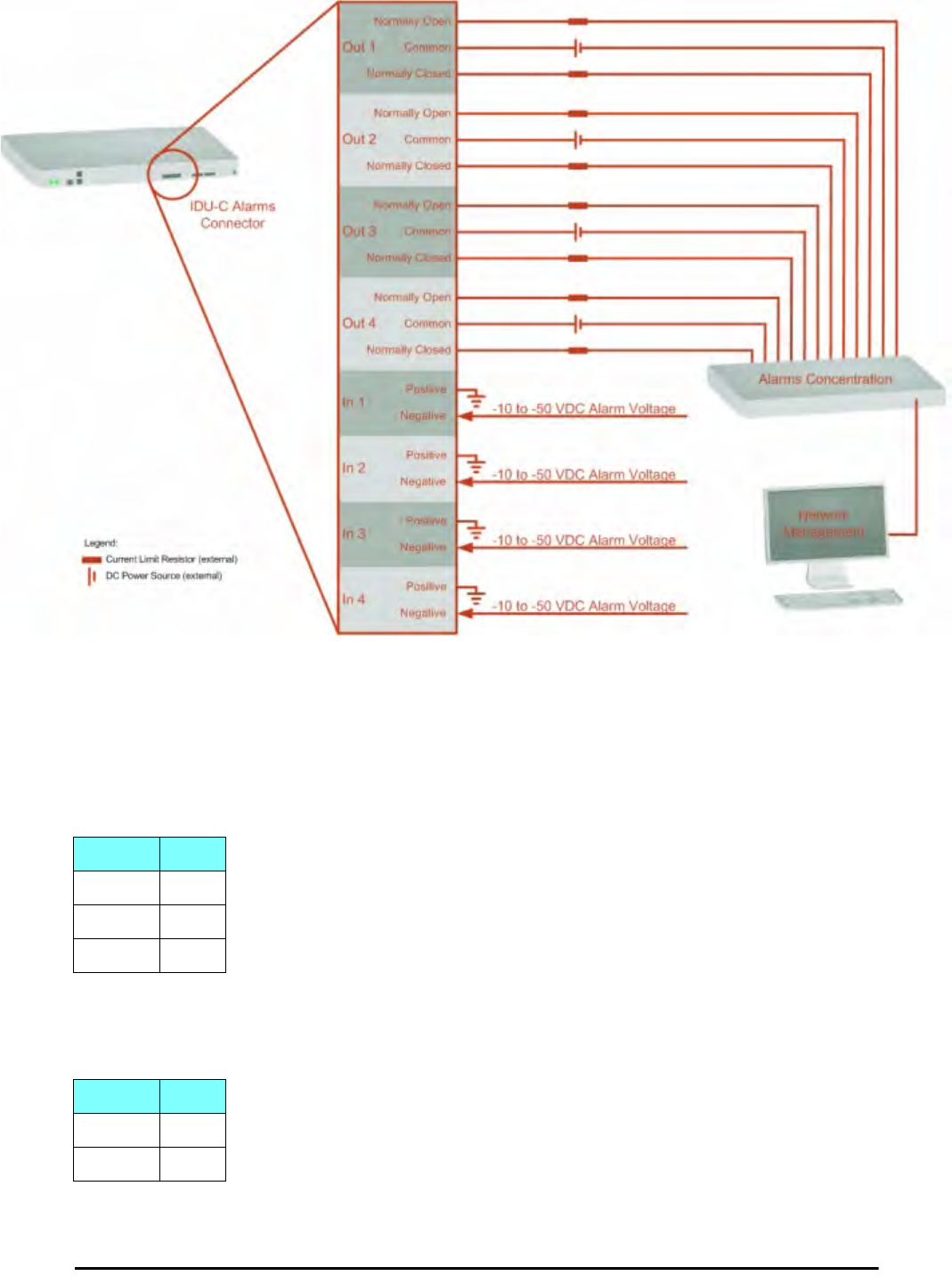
DC Power Terminals Appendix B
RADWIN 2000 User Manual Release 2.5.40 B-4
Figure B-1: Example for connecting the alarm connector
DC Power Terminals
IDU-C & E
DC PoE
Table B-7: Terminal Block 3-pin -48VDC
Function Pin
+Right
Chassis Center
–Left
Table B-8: Terminal Block 2-pin -48VDC
Function Pin
+Right
–Left

DC PoE Appendix B
RADWIN 2000 User Manual Release 2.5.40 B-5

RADWIN 2000 User Manual Release 2.5.40 C-1
Appendix C
Small Form-factor
Pluggable Transceiver
IDU-C SFP Support
The Small Form-factor Pluggable (SFP) transceiver, is a compact, hot-pluggable transceiver
used in communications applications.
The SFP transceiver technology allows almost any protocol converter implementation with
seamless integration to a standard Ethernet switch.
The IDU-C supports SFP transceivers to provide and support several network applications.
Any standard Fast Ethernet (FE) SFP transceiver can be plugged into the IDU-C. These SFPs
support various Ethernet interfaces. For example a fibre optic interface can be used to sup-
port long fibre distances.
In addition, System on SFP transceivers can be used, supporting a
protocol converter
con-
cept. The main application for such SFP transceivers is
TDM over Ethernet
providing E1/T1
or E3/T3 over full duplex Ethernet Remote Bridge
The following table provides a few SFP types that can be used with the IDU-C:
Table C-1: SFP Type and Interface description
SFP Type Interface Description
100baseT 100BaseT, IEEE 802.3, UTP CAT5
100baseFX Multimode fiber-optic (MMF) link spans up to 2km long
100baseLX Single-mode fiber optic (SMF) links pans up to 10km
100baseBX SMF single-strand link spans up to 10 km or 40 km
E3T3/FE E3/T3

RADWIN 2000 User Manual Release 2.5.40 D-1
Appendix D
MIB Reference
Introduction
About the MIB
The RADWIN MIB is a set of APIs that enables external applications to control RADWIN
equipment.
The MIB is divided into public and a private API groups:
•Public: RFC-1213 (MIB II) variables, RFC-1214 (MIB II) System and Interfaces sec-
tions
•Private: Controlled by RADWIN and supplements the public group.
This appendix describes the public and private MIB used by RADWIN.
Terminology
The following terms are used in this appendix.
In addition, the MIB uses internally, the older notions of Local site and Remote site where
this manual would use site A and site B.
To avoid burdening the reader, this appendix will follow the MIB usage.
Interface API
Control Method
The RADWIN Manager application provides all the means to configure and monitor a RADWIN
2000 link, communicating with the SNMP agent in each ODU. Each SNMP agent contains data
Term Meaning
MIB Management Information Base
API Application Programming Interface
SNMP Simple Network Management Protocol

Community String Appendix D
RADWIN 2000 User Manual Release 2.5.40 D-2
on each of the IDUs and ODUs in the link. Both agents communicate with each other over the
air using a proprietary protocol.
To control and configure the device using the MIB, you should adhere to the following rules:
• The connection for control and configuration is to the local site, over any SNMP/UDP/
IP network.
• All Parameters should be consistent between both of the ODUs. Note that inconsis-
tency of air parameters can break the air connection. To correct air parameters incon-
sistency you must reconfigure each of the ODUs.
• Common practice is to configure the remote site first and then to configure the local
site.
• For some of the configuration parameters additional action must be taken before the
new value is loaded. Please refer to the operation in the parameters description.
• Some of the MIB parameters values are product dependent. It is strongly recommend
using the RADWIN Manager Application for changing these values. Setting wrong val-
ues may cause indeterminate results.
Community String
To control a link, all SNMP requests should go to the local site IP address.
See Table 4-4 for default Community strings.
Private MIB Structure
The sections in the private RADWIN MIB and its location in the MIB tree are shown in
Figure D-1 below:
Note
Each ODU has a single MAC address and a single IP address.
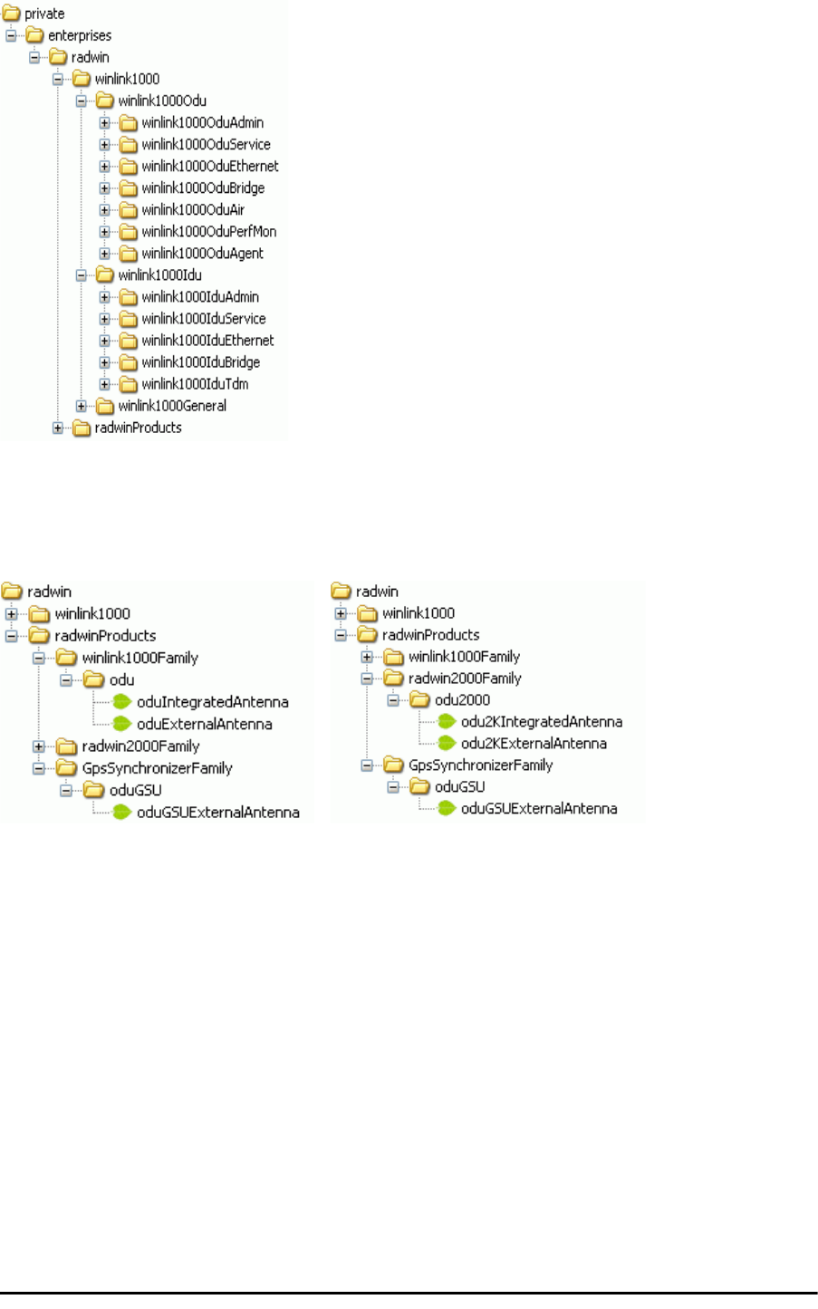
MIB Parameters Appendix D
RADWIN 2000 User Manual Release 2.5.40 D-3
Figure D-1: Top Level Sections of the private MIB
The products MIB section contains the definition of the Object IDs for the two form factors of
the ODU, Integrated Antenna and Connectorized (referred in the MIB as external antenna)
and GSU (where applicable):
Figure D-2: Product MIB: Left WinLink 1000, Right RADWIN 2000
The ODU MIB contains the sections: Admin, Service, Ethernet, Bridge, Air, PerfMon and
Agent.
The IDU MIB contains the sections: Admin, Service, Ethernet, Bridge and TDM.
The GpsSynchronizerFamily MIB defines the GSU.
The general MIB include a single generic parameter that is used by all traps as a trap descrip-
tion parameter.
MIB Parameters
The following section describes all of the MIB parameters. The MIB parameters follow the fol-
lowing naming convention:
<winlink1000><Section 1>...<Section n><Parameter Name>

Supported Variables from the RFC 1213 MIB Appendix D
RADWIN 2000 User Manual Release 2.5.40 D-4
For each of the configuration and control parameters (parameters with read-write access),
the “Description” column describes when the new value is effective. It is recommended that
you perform the appropriate action to make the values affective immediately after any
change. Where a change is required on both sides of the link, it is recommended that you
change both sides of the link first and then perform the action.
Supported Variables from the RFC 1213 MIB
Table D-1: Supported RFC 1213 Variables (Sheet 1 of 2)
Name OID Type
Access
Description
ifIndex .1.3.6.1.2.1.2.2.1.1.xaInteger RO A unique value for each interface.Its value ranges
between 1 and the value of ifNumber.The value for
each interface must remain constant at least from
one re-initialization of the entity's network
management system to the next re-initialization.
ifDescr .1.3.6.1.2.1.2.2.1.2 DisplayString RO A textual string containing information about the
interface.This string should include the name of
the manufacturer, the product name and the
version of the hardware interface.
ifType .1.3.6.1.2.1.2.2.1.3 Integer RO The type of interface, distinguished according to
the physical/link protocol(s) immediately `below'
the network layer in the protocol stack.
ifSpeed .1.3.6.1.2.1.2.2.1.5 Gauge RO An estimate of the interface's current bandwidth in
bits per second.For interfaces which do not vary in
bandwidth or for those where no accurate
estimation can be made, this object should ontain
the nominal bandwidth.
ifPhysAddress .1.3.6.1.2.1.2.2.1.6 Phys-Address RO The interface's address at the protocol layer
immediately `below' the network layer in the
protocol stack. For interfaces which do not have
such an address (e.g., a serial line), this object
should contain an octet string of zero length.
ifAdminStatus .1.3.6.1.2.1.2.2.1.7 Integer RW The desired state of the interface. The testing(3)
state indicates that no operational packets can be
passed.
ifOperStatus .1.3.6.1.2.1.2.2.1.8 Integer RO The current operational state of the interface. The
testing(3) state indicates that no operational
packets can be passed.
ifInOctets .1.3.6.1.2.1.2.2.1.10.x Counter RO The total number of octets received on the
interface, including framing characters.
ifInUcastPkts .1.3.6.1.2.1.2.2.1.11.x Counter RO The number of subnetwork-unicast packets
delivered to a higher-layer protocol.
ifInNUcastPkts .1.3.6.1.2.1.2.2.1.12.x Counter RO The number of non-unicast (i.e., subnetwork-
broadcast or subnetwork-multicast) packets
delivered to a higher-layer protocol.
ifInErrors .1.3.6.1.2.1.2.2.1.14.x Counter RO The number of inbound packets that contained
errors preventing them from being deliverable to a
higher-layer protocol.
ifOutOctets .1.3.6.1.2.1.2.2.1.16.x Counter RO The total number of octets transmitted out of the
interface, including framing characters.
ifOutUcastPkts .1.3.6.1.2.1.2.2.1.17.x Counter RO The total number of packets that higher-level
protocols requested be transmitted to a
subnetwork-unicast address, including those that
were discarded or not sent.

Supported Variables from the RFC 1213 MIB Appendix D
RADWIN 2000 User Manual Release 2.5.40 D-5
ifOutNUcastPkts .1.3.6.1.2.1.2.2.1.18.x Counter RO The total number of packets that higher-level
protocols requested be transmitted to a non-
unicast (i.e., a subnetwork-broadcast or
subnetwork-multicast) address, including those
that were discarded or not sent.
a. x is the interface ID
Table D-1: Supported RFC 1213 Variables (Sheet 2 of 2)
Name OID Type
Access
Description

MIB Parameters Appendix D
RADWIN 2000 User Manual Release 2.5.40 D-6
MIB Parameters
Table D-2: Private MIB Parameters (Sheet 1 of 18)
Name OID Type
Access
Description
winlink1000OduAdmProductType 1.3.6.1.4.1.4458.1000.1.1.1 DisplayString RO ODU configuration description.
winlink1000OduAdmHwRev 1.3.6.1.4.1.4458.1000.1.1.2 DisplayString RO ODU Hardware Version.
winlink1000OduAdmSwRev 1.3.6.1.4.1.4458.1000.1.1.3 DisplayString RO ODU Software Version.
winlink1000OduAdmLinkName 1.3.6.1.4.1.4458.1000.1.1.4 DisplayString RW Link Name. A change is effective immediately.
winlink1000OduAdmResetCmd 1.3.6.1.4.1.4458.1000.1.1.5 Integer RW Reset Command. A set command with a value of 3
will cause a device reset. The read value is
always 0.
winlink1000OduAdmAddres 1.3.6.1.4.1.4458.1000.1.1.6 IpAddress RW ODU IP address. A change is effective after reset.
The parameter is kept for backward compatibility.
Using the alternative parameter:
winlink1000OduAdmIpParamsCnfg is
recommended.
winlink1000OduAdmMask 1.3.6.1.4.1.4458.1000.1.1.7 IpAddress RW ODU Subnet Mask. A change is effective after
reset. The parameter is kept for backward
compatibility. Using the alternative parameter:
winlink1000OduAdmIpParamsCnfg is
recommended.
winlink1000OduAdmGateway 1.3.6.1.4.1.4458.1000.1.1.8 IpAddress RW ODU default gateway. A change is effective after
reset. The parameter is kept for backward
compatibility. Using the alternative parameter:
winlink1000OduAdmIpParamsCnfg is
recommended.
winlink1000OduAdmBroadcast 1.3.6.1.4.1.4458.1000.1.1.10 Integer RW This parameter is reserved for the Manager
application provided with the product.
winlink1000OduAdmHostsTable N/A Trap destinations table. Each trap destination is
defined by an IP address and a UDP port. Up to
10 addresses can be configured.
winlink1000OduAdmHostsEntry N/A Trap destinations table entry. INDEX {
winlink1000OduAdmHostsIndex }
winlink1000OduAdmHostsIndex RO Trap destinations table index.
winlink1000OduAdmHostsIp 1.3.6.1.4.1.4458.1000.1.1.12.1.2 IpAddress RW Trap destination IP address. A change is effective
immediately.
winlink1000OduAdmHostsPort 1.3.6.1.4.1.4458.1000.1.1.12.1.3 Integer RW UDP port of the trap destination. A change is
effective immediately.
winlink1000OduBuzzerAdminState 1.3.6.1.4.1.4458.1000.1.1.13 Integer RW This parameter controls the activation of the
buzzer while the unit is in install mode. A change
is effective immediately. The valid values are:
disabled (0) enabledAuto (1)
enabledConstantly(2).
winlink1000OduProductId 1.3.6.1.4.1.4458.1000.1.1.14 DisplayString RO This parameter is reserved for the Manager
application provided with the product.
winlink1000OduReadCommunity 1.3.6.1.4.1.4458.1000.1.1.15 DisplayString RW Read Community String. This parameter always
returns ***** when retrieving its value. It is used
by the Manager application to change the Read
Community String. The SNMP agent accepts only
encrypted values.
winlink1000OduReadWriteCommunity 1.3.6.1.4.1.4458.1000.1.1.16 DisplayString RW Read/Write Community String. This parameter
always returns ***** when retrieving its value. It is
used by the Manager application to change the
Read/Write Community String. The SNMP agent
accepts only encrypted values.
winlink1000OduTrapCommunity 1.3.6.1.4.1.4458.1000.1.1.17 DisplayString RW Trap Community String. This parameter is used by
the Manager application to change the Trap
Community String. The SNMP agent accepts only
encrypted values.

MIB Parameters Appendix D
RADWIN 2000 User Manual Release 2.5.40 D-7
winlink1000OduAdmSnmpAgentVersion 1.3.6.1.4.1.4458.1000.1.1.18 Integer RO Major version of the SNMP agent.
winlink1000OduAdmRemoteSiteName 1.3.6.1.4.1.4458.1000.1.1.19 DisplayString RO Remote site name. Returns the same value as
sysLocation parameter of the remote site.
winlink1000OduAdmSnmpAgentMinorVersion 1.3.6.1.4.1.4458.1000.1.1.20 Integer RO Minor version of the SNMP agent.
winlink1000OduAdmLinkPassword 1.3.6.1.4.1.4458.1000.1.1.21 DisplayString RW Link Password. This parameter always returns
***** when retrieving its value. It is used by the
Manager application to change the Link Password.
The SNMP agent accepts only encrypted values.
winlink1000OduAdmSiteLinkPassword 1.3.6.1.4.1.4458.1000.1.1.22 DisplayString RW Site Link Password. This parameter always returns
***** when retrieving its value. It is used by the
Manager application to change the Link Password
of the site. The SNMP agent accepts only
encrypted values.
winlink1000OduAdmDefaultPassword 1.3.6.1.4.1.4458.1000.1.1.23 Integer RO This parameter indicates if the current Link
Password is the default password.
winlink1000OduAdmConnectionType 1.3.6.1.4.1.4458.1000.1.1.24 Integer RO This parameter indicates if the Manager
application is connected to the local ODU or to
the remote ODU over the air. A value of 'unknown'
indicates community string mismatch.
winlink1000OduAdmBackToFactorySettingsC
md
1.3.6.1.4.1.4458.1000.1.1.25 Integer RW Back to factory settings Command. A change is
effective after reset. The read value is always 0.
winlink1000OduAdmIpParamsCnfg 1.3.6.1.4.1.4458.1000.1.1.26 DisplayString RW ODU IP address Configuration. The format is:
<IP_Address>|<Subnet_Mask>|<Default_Gatewa
y>|
winlink1000OduAdmVlanID 1.3.6.1.4.1.4458.1000.1.1.27 Integer RW VLAN ID. Valid values are 1 to 4094. Initial value
is 0 meaning VLAN unaware.
winlink1000OduAdmVlanPriority 1.3.6.1.4.1.4458.1000.1.1.28 Integer RW VLAN Priority. 0 is lowest priority 7 is highest
priority.
winlink1000OduAdmSN 1.3.6.1.4.1.4458.1000.1.1.29 DisplayString RO ODU Serial Number
winlink1000OduAdmProductName 1.3.6.1.4.1.4458.1000.1.1.30 DisplayString RO This is the product name as it exists at EC
winlink1000OduAdmActivationKey 1.3.6.1.4.1.4458.1000.1.1.31 DisplayString RW Activates a general key.
winlink1000OduAdmRmtPermittedOduType 1.3.6.1.4.1.4458.1000.1.1.32 DisplayString RW Mobile Application: permitted partner OduType.
winlink1000OduAdmCpuID 1.3.6.1.4.1.4458.1000.1.1.33 Integer RO CPU ID
winlink1000OduSrvMode 1.3.6.1.4.1.4458.1000.1.2.1 Integer RW System mode. The only values that can be set are
installMode and slaveMode; normalMode
reserved to the Manager application provided with
the product. A change is effective after link re-
synchronization.
winlink1000OduSrvBridging 1.3.6.1.4.1.4458.1000.1.2.3 Integer RO Bridging Mode. Valid values are: disabled (0)
enabled (1).
winlink1000OduSrvRingLinkMode 1.3.6.1.4.1.4458.1000.1.2.4.1 Integer RW Mode of the link regarding ring topology.
winlink1000OduSrvRingTopologySupported 1.3.6.1.4.1.4458.1000.1.2.4.2 Integer RO Ring Topology options are: supported not
supported
winlink1000OduSrvRingVlanIdTable N/A Ring VLAN IDs table.
winlink1000OduSrvRingVlanIdEntry N/A VLAN ID of the internal ring messages. Valid
values are 1 to 4094. Initial value is 0 meaning
VLAN unaware. INDEX {
winlink1000OduSrvRingVlanIdIndex }
winlink1000OduSrvRingVlanIdIndex 1.3.6.1.4.1.4458.1000.1.2.4.3.1.1 Integer RO Index of VLAN ID of the internal ring messages.
winlink1000OduSrvRingVlanId 1.3.6.1.4.1.4458.1000.1.2.4.3.1.2 Integer RW VLAN ID of the internal ring messages. Valid
values are 1 to 4094. Initial value is 0 meaning
VLAN unaware.
winlink1000OduSrvRingEthStatus 1.3.6.1.4.1.4458.1000.1.2.4.4 Integer RO Represents the Ethernet service blocking state of
a Rings link
Table D-2: Private MIB Parameters (Sheet 2 of 18)
Name OID Type
Access
Description

MIB Parameters Appendix D
RADWIN 2000 User Manual Release 2.5.40 D-8
winlink1000OduSrvRingMaxAllowedTimeFrom
LastRpm
1.3.6.1.4.1.4458.1000.1.2.4.5 Integer RW Defines the minimal time (in ms) required for
determination of ring failure.
winlink1000OduSrvRingWTR 1.3.6.1.4.1.4458.1000.1.2.4.6 Integer RW Defines the minimal time (in ms) required for ring
recovery.
winlink1000OduSrvQoSMode 1.3.6.1.4.1.4458.1000.1.2.5.1 Integer RW Mode of QoS feature.
winlink1000OduSrvQoSConfTable N/A QoS configuration table.
winlink1000OduSrvQoSConfEntry N/A QoS configuration table. INDEX {
winlink1000OduSrvQoSConfIndex }
winlink1000OduSrvQoSConfIndex 1.3.6.1.4.1.4458.1000.1.2.5.2.1.1 Integer RO Index of QoS Configuration.
winlink1000OduSrvConfVlanQGroups 1.3.6.1.4.1.4458.1000.1.2.5.2.1.2 Integer RO Frames classification according to VLAN Priority
IDs.
winlink1000OduSrvConfDiffservQGroups 1.3.6.1.4.1.4458.1000.1.2.5.2.1.3 Integer RO Frames classification according to Diffserv.
winlink1000OduSrvConfQueMir 1.3.6.1.4.1.4458.1000.1.2.5.2.1.4 Integer RW Desired Private MIR.
winlink1000OduSrvConfQueWeight 1.3.6.1.4.1.4458.1000.1.2.5.2.1.5 Integer RW QoS queueu's weights in percent.
winlink1000OduSrvQoSVlanQGroupsSetStr 1.3.6.1.4.1.4458.1000.1.2.5.3 DisplayString RW Frames classification according to VLAN IDs string
for set.
winlink1000OduSrvQoSDiffservQGroupsSetStr 1.3.6.1.4.1.4458.1000.1.2.5.4 DisplayString RW Frames classification according to Diffserv IDs
string for set.
winlink1000OduSrvQoSMaxRTQuePercent 1.3.6.1.4.1.4458.1000.1.2.5.5 Integer RO Maximal percent for RT & NRT queues.
winlink1000OduEthernetRemainingRate 1.3.6.1.4.1.4458.1000.1.3.1 Integer RO Current Ethernet bandwidth in bps.
winlink1000OduEthernetIfTable N/A ODU Ethernet Interface table.
winlink1000OduEthernetIfEntry N/A ODU Ethernet Interface table entry. INDEX {
winlink1000OduEthernetIfIndex }
winlink1000OduEthernetIfIndex 1.3.6.1.4.1.4458.1000.1.3.2.1.1 Integer RO ODU Ethernet Interface Index.
winlink1000OduEthernetIfAddress 1.3.6.1.4.1.4458.1000.1.3.2.1.5 DisplayString RO ODU MAC address.
winlink1000OduEthernetIfAdminStatus 1.3.6.1.4.1.4458.1000.1.3.2.1.6 Integer RW Required state of the interface.
winlink1000OduEthernetIfOperStatus 1.3.6.1.4.1.4458.1000.1.3.2.1.7 Integer RO Current operational state of the interface.
winlink1000OduEthernetIfFailAction 1.3.6.1.4.1.4458.1000.1.3.2.1.8 Integer RW Failure action of the interface.
winlink1000OduEthernetNumOfPorts 1.3.6.1.4.1.4458.1000.1.3.3 Integer RO Number of ODU network interfaces.
winlink1000OduBridgeBasePortTable N/A ODU Bridge Ports table.
winlink1000OduBridgeBasePortEntry N/A ODU Bridge Ports table entry. INDEX {
winlink1000OduBridgeBasePortIndex }
winlink1000OduBridgeBasePortIndex RO ODU Bridge Port Number.
winlink1000OduBridgeBaseIfIndex RO IfIndex corresponding to ODU Bridge port.
winlink1000OduBridgeTpMode 1.3.6.1.4.1.4458.1000.1.4.4.101 Integer RW ODU bridge mode. A change is effective after
reset. Valid values: hubMode (0) bridgeMode (1).
winlink1000OduBridgeTpPortTable N/A ODU Transparent Bridge Ports table.
winlink1000OduBridgeTpPortEntry N/A ODU Transparent Bridge Ports table entry.
INDEX { winlink1000OduBridgeTpPortIndex }
winlink1000OduBridgeTpPortIndex RO ODU Transparent Bridge Port Number.
winlink1000OduBridgeTpPortInFrames 1.3.6.1.4.1.4458.1000.1.4.4.3.1.3 Counter RO Number of frames received by this port.
winlink1000OduBridgeTpPortOutFrames 1.3.6.1.4.1.4458.1000.1.4.4.3.1.4 Counter RO Number of frames transmitted by this port.
winlink1000OduBridgeTpPortInBytes 1.3.6.1.4.1.4458.1000.1.4.4.3.1.10
1
Counter RO Number of bytes received by this port.
winlink1000OduBridgeTpPortOutBytes 1.3.6.1.4.1.4458.1000.1.4.4.3.1.10
2
Counter RO Number of bytes transmitted by this port.
winlink1000OduBridgeConfigMode 1.3.6.1.4.1.4458.1000.1.4.4.102 Integer RO ODU bridge configuration mode
winlink1000OduAirFreq 1.3.6.1.4.1.4458.1000.1.5.1 Integer RW Installation Center Frequency. Valid values are
product dependent. A change is effective after link
re-synchronization.
Table D-2: Private MIB Parameters (Sheet 3 of 18)
Name OID Type
Access
Description

MIB Parameters Appendix D
RADWIN 2000 User Manual Release 2.5.40 D-9
winlink1000OduAirDesiredRate 1.3.6.1.4.1.4458.1000.1.5.2 Integer RW Deprecated parameter actual behavior is read-
only. Required Air Rate. For Channel Bandwidth
of 20 10 5 MHz divide the value by 1 2 4
respectively.
winlink1000OduAirSSID 1.3.6.1.4.1.4458.1000.1.5.3 DisplayString RW Reserved for the Manager application provided
with the product.
winlink1000OduAirTxPower 1.3.6.1.4.1.4458.1000.1.5.4 Integer RW Required Transmit power in dBm . This is a
nominal value while the actual transmit power
includes additional attenuation. The min and max
values are product specific. A change is effective
immediately.
winlink1000OduAirSesState 1.3.6.1.4.1.4458.1000.1.5.5 Integer RO Current Link State. The value is active (3) during
normal operation.
winlink1000OduAirMstrSlv 1.3.6.1.4.1.4458.1000.1.5.6 Integer RO This parameter indicates if the device was
automatically selected into the radio link master or
slave. The value is undefined if there is no link.
winlink1000OduAirResync 1.3.6.1.4.1.4458.1000.1.5.8 Integer RW Setting this parameter to 1 will cause the link to
restart the synchronization process.
winlink1000OduAirRxPower 1.3.6.1.4.1.4458.1000.1.5.9.1 Integer RO Received Signal Strength in dBm.
winlink1000OduAirTotalFrames 1.3.6.1.4.1.4458.1000.1.5.9.2 Counter RO Total Number of received radio frames.
winlink1000OduAirBadFrames 1.3.6.1.4.1.4458.1000.1.5.9.3 Counter RO Total number of received radio frames with CRC
error.
winlink1000OduAirCurrentRate 1.3.6.1.4.1.4458.1000.1.5.9.4 Integer RO Deprecated parameter. Actual rate of the air
interface in Mbps. For Channel Bandwidth of 20
10 5 MHz divide the value by 1 2 4 respectively.
winlink1000OduAirCurrentRateIdx 1.3.6.1.4.1.4458.1000.1.5.9.5 Integer RO Index of current air rate.
winlink1000OduAirTxPower36 1.3.6.1.4.1.4458.1000.1.5.10 Integer RW Deprecated parameter. Actual behavior is read-
only.
winlink1000OduAirTxPower48 1.3.6.1.4.1.4458.1000.1.5.11 Integer RW Deprecated parameter. Actual behavior is read-
only.
winlink1000OduAirCurrentTxPower 1.3.6.1.4.1.4458.1000.1.5.12 Integer RO Current Transmit Power in dBm. This is a nominal
value while the actual transmit power includes
additional attenuation.
winlink1000OduAirMinFrequency 1.3.6.1.4.1.4458.1000.1.5.13 Integer RO Minimum center frequency in MHz.
winlink1000OduAirMaxFrequency 1.3.6.1.4.1.4458.1000.1.5.14 Integer RO Maximum center frequency in MHz.
winlink1000OduAirFreqResolution 1.3.6.1.4.1.4458.1000.1.5.15 Integer RO Center Frequency resolution. Measured in MHz
if value < 100 otherwise in KHz.
winlink1000OduAirCurrentFreq 1.3.6.1.4.1.4458.1000.1.5.16 Integer RO Current Center Frequency. Measured in MHz if
center frequency resolution value < 100 otherwise
in KHz.
winlink1000OduAirNumberOfChannels 1.3.6.1.4.1.4458.1000.1.5.17 Integer RO Number of channels that can be used.
winlink1000OduAirChannelsTable N/A Table of channels used by automatic channels
selection (ACS).
winlink1000OduAirChannelsEntry N/A ACS channels table entry. INDEX {
winlink1000OduAirChannelsIndex }
winlink1000OduAirChannelsIndex 1.3.6.1.4.1.4458.1000.1.5.18.1.1 Integer RO Channel Index.
winlink1000OduAirChannelsFrequency 1.3.6.1.4.1.4458.1000.1.5.18.1.2 Integer RO Channel frequency in MHz.
winlink1000OduAirChannelsOperState 1.3.6.1.4.1.4458.1000.1.5.18.1.3 Integer RW Channel state. Can be set by the user.
Automatic Channel Selection uses channels that
are AirChannelsOperState enabled and
AirChannelsAvail enabled. A change is effective
after link re-synchronization. Valid values: disabled
(0) enabled (1).
Table D-2: Private MIB Parameters (Sheet 4 of 18)
Name OID Type
Access
Description

MIB Parameters Appendix D
RADWIN 2000 User Manual Release 2.5.40 D-10
winlink1000OduAirChannelsAvail 1.3.6.1.4.1.4458.1000.1.5.18.1.4 Integer RO Channel state. Product specific and cannot be
changed by the user. Automatic Channel
Selection uses channels that are
AirChannelsOperState enabled and
AirChannelsAvail enabled. Valid values: disabled
(0) enabled (1).
winlink1000OduAirChannelsDefaultFreq 1.3.6.1.4.1.4458.1000.1.5.18.1.5 Integer RO Default channel's availability for all CBWs. The
valid values are: forbidden (0) available (1).
winlink1000OduAirDfsState 1.3.6.1.4.1.4458.1000.1.5.19 Integer RO Radar detection state. Valid values: disabled (0)
enabled (1).
winlink1000OduAirAutoChannelSelectionState 1.3.6.1.4.1.4458.1000.1.5.20 Integer RO Deprecated parameter. Indicating Automatic
Channel Selection availability at current channel
bandwidth. Valid values: disabled (0) enabled
(1).
winlink1000OduAirEnableTxPower 1.3.6.1.4.1.4458.1000.1.5.21 Integer RO Indicating Transmit power configuration enabled or
disabled.
winlink1000OduAirMinTxPower 1.3.6.1.4.1.4458.1000.1.5.22 Integer RO Minimum Transmit power in dBm.
winlink1000OduAirMaxTxPowerTable N/A Table of Maximum transmit power per air rate in
dBm.
winlink1000OduAirMaxTxPowerEntry N/A Maximum Transmit power table entry. INDEX {
winlink1000OduAirMaxTxPowerIndex }
winlink1000OduAirMaxTxPowerIndex 1.3.6.1.4.1.4458.1000.1.5.23.1.1 Integer RO Air interface rate index.
winlink1000OduAirMaxTxPower 1.3.6.1.4.1.4458.1000.1.5.23.1.2 Integer RO Maximum Transmit power in dBm.
winlink1000OduAirChannelBandwidth 1.3.6.1.4.1.4458.1000.1.5.24 Integer RW Channel bandwidth in KHz. A change is effective
after reset.
winlink1000OduAirChannelBWTable N/A Channel Bandwidths table.
winlink1000OduAirChannelBWEntry N/A Channel Bandwidth table entry. INDEX {
winlink1000OduAirChannelBWIndex }
winlink1000OduAirChannelBWIndex 1.3.6.1.4.1.4458.1000.1.5.25.1.1 Integer RO Channel Bandwidth index.
winlink1000OduAirChannelBWAvail 1.3.6.1.4.1.4458.1000.1.5.25.1.2 Integer RO Channel Bandwidth availability product specific.
Options are: Not supported supported with
manual channel selection supported with
Automatic Channel Selection.
winlink1000OduAirChannelsAdminState 1.3.6.1.4.1.4458.1000.1.5.25.1.3 DisplayString RO Channels' availability per CBW.
winlink1000OduAirChannelBWHSSATDDConfl
ictPerCBW
1.3.6.1.4.1.4458.1000.1.5.25.1.4 Integer RO Indication for possible Link drop per CBW due to
conflict between HSS and ATDD.
winlink1000OduAirChannelBWMinRatioForSu
pporting
1.3.6.1.4.1.4458.1000.1.5.25.1.5 Integer RO Minimal TX ratio that may be used by the HSM and
still enable proper operation of the aforementioned
CBW.
winlink1000OduAirChannelBWMaxRatioForSu
pporting
1.3.6.1.4.1.4458.1000.1.5.25.1.6 Integer RO Maximal TX ratio that may be used by the HSM
and still enable proper operation of the
aforementioned CBW.
winlink1000OduAirRFD 1.3.6.1.4.1.4458.1000.1.5.26 Integer RO Current radio frame duration in microseconds.
winlink1000OduAirRatesTable N/A Air Rate indexes table for current channel
bandwidth.
winlink1000OduAirRatesEntry N/A Air Rate indexes table entry. INDEX {
winlink1000OduAirRatesIndex }
winlink1000OduAirRatesIndex 1.3.6.1.4.1.4458.1000.1.5.27.1.1 Integer RO Air Rate index.
winlink1000OduAirRatesAvail 1.3.6.1.4.1.4458.1000.1.5.27.1.2 Integer RO Air Rate availability depending on air interface
conditions.
winlink1000OduAirDesiredRateIdx 1.3.6.1.4.1.4458.1000.1.5.28 Integer RW Required Air Rate index. 0 reserved for Adaptive
Rate. A change is effective immediately after Set
operation to the master side while the link is up.
Table D-2: Private MIB Parameters (Sheet 5 of 18)
Name OID Type
Access
Description

MIB Parameters Appendix D
RADWIN 2000 User Manual Release 2.5.40 D-11
winlink1000OduAirLinkDistance 1.3.6.1.4.1.4458.1000.1.5.29 Integer RO Link distance in meters. A value of -1 indicates
an illegal value and is also used when a link is not
established.
winlink1000OduAirLinkWorkingMode 1.3.6.1.4.1.4458.1000.1.5.30 Integer RO Link working mode as a result of comparing
versions of both sides of the link. Possible
modes are: Unknown - no link Normal - versions
on both sides are identical with full compatibility
with restricted compatibility or versions on both
sides are different with software upgrade or
versions incompatibility.
winlink1000OduAirMajorLinkIfVersion 1.3.6.1.4.1.4458.1000.1.5.31 Integer RO Major link interface version
winlink1000OduAirMinorLinkIfVersion 1.3.6.1.4.1.4458.1000.1.5.32 Integer RO Minor link interface version
winlink1000OduAirHssDesiredOpState 1.3.6.1.4.1.4458.1000.1.5.40.1 Integer RW Required Hub Site Synchronization operating
state.
winlink1000OduAirHssCurrentOpState 1.3.6.1.4.1.4458.1000.1.5.40.2 Integer RO Current Hub Site Synchronization operating state.
winlink1000OduAirHssSyncStatus 1.3.6.1.4.1.4458.1000.1.5.40.3 Integer RO Hub Site Synchronization sync status.
winlink1000OduAirHssExtPulseStatus 1.3.6.1.4.1.4458.1000.1.5.40.4 Integer RO Hub Site Synchronization external pulse detection
status. In GSS mode: if generating then 1PSP
is auto generated by the GSS Unit. if
generatingAndDetecting then 1PSP is generated
by GPS satellites signal.
winlink1000OduAirHssExtPulseType 1.3.6.1.4.1.4458.1000.1.5.40.5 Integer RO Hub Site Synchronization external pulse type.
winlink1000OduAirHssDesiredExtPulseType 1.3.6.1.4.1.4458.1000.1.5.40.6 Integer RW Hub Site Synchronization required external pulse
type. Valid values for read write: {typeA(2)
typeB(3) typeC(4) typeD(5) typeE(6) typeF(7)}.
Valid value for read only: {notApplicable(1)}.
winlink1000OduAirHssRfpTable N/A ODU Radio Frame Patterns (RFP) Table.
winlink1000OduAirHssRfpEntry N/A ODU RFP Table entry. INDEX {
winlink1000OduAirHssRfpIndex }
winlink1000OduAirHssRfpIndex 1.3.6.1.4.1.4458.1000.1.5.40.7.1.1 Integer RO ODU RFP Table index. The index represent the
Radio Frame Pattern: typeA(2) typeB(3)
typeC(4) typeD(5) typeE(6).
winlink1000OduAirHssRfpEthChannelBW5MH
z
1.3.6.1.4.1.4458.1000.1.5.40.7.1.2 Integer RO Represents the compatibility of Ethernet service
under Channel BW of 5MHz in the specific
Radio Frame Pattern.
winlink1000OduAirHssRfpTdmChannelBW5M
Hz
1.3.6.1.4.1.4458.1000.1.5.40.7.1.3 Integer RO Represents the compatibility of TDM service under
Channel BW of 5MHz in the specific Radio
Frame Pattern.
winlink1000OduAirHssRfpEthChannelBW10M
Hz
1.3.6.1.4.1.4458.1000.1.5.40.7.1.4 Integer RO Represents the compatibility of Ethernet service
under Channel BW of 10MHz in the specific
Radio Frame Pattern.
winlink1000OduAirHssRfpTdmChannelBW10
MHz
1.3.6.1.4.1.4458.1000.1.5.40.7.1.5 Integer RO Represents the compatibility of TDM service under
Channel BW of 10MHz in the specific Radio
Frame Pattern.
winlink1000OduAirHssRfpEthChannelBW20M
Hz
1.3.6.1.4.1.4458.1000.1.5.40.7.1.6 Integer RO Represents the compatibility of Ethernet service
under Channel BW of 20MHz in the specific
Radio Frame Pattern.
winlink1000OduAirHssRfpTdmChannelBW20
MHz
1.3.6.1.4.1.4458.1000.1.5.40.7.1.7 Integer RO Represents the compatibility of TDM service under
Channel BW of 20MHz in the specific Radio
Frame Pattern.
winlink1000OduAirHssRfpEthChannelBW40M
Hz
RO Represents the compatibility of Ethernet service
under Channel BW of 40MHz in the specific
Radio Frame Pattern.
winlink1000OduAirHssRfpTdmChannelBW40
MHz
RO Represents the compatibility of TDM service under
Channel BW of 40MHz in the specific Radio
Frame Pattern.
winlink1000OduAirHssRfpStr 1.3.6.1.4.1.4458.1000.1.5.40.8 DisplayString RO Hub Site Synchronization supported patterns
Table D-2: Private MIB Parameters (Sheet 6 of 18)
Name OID Type
Access
Description

MIB Parameters Appendix D
RADWIN 2000 User Manual Release 2.5.40 D-12
winlink1000OduAirHSSHsmID 1.3.6.1.4.1.4458.1000.1.5.40.9 Integer RO A unique ID which is common to the HSM and all
its collocated ODUs
winlink1000OduAirHssTime 1.3.6.1.4.1.4458.1000.1.5.40.10.0 DisplayString RO Hub Site Synchronization GPS time
winlink1000OduAirHssLatitude 1.3.6.1.4.1.4458.1000.1.5.40.11.0 DisplayString RO Hub Site Synchronization GPS Latitude
winlink1000OduAirHssNSIndicator 1.3.6.1.4.1.4458.1000.1.5.40.12.0 DisplayString RO Hub Site Synchronization GPS N/S Indicator
winlink1000OduAirHssLongitude 1.3.6.1.4.1.4458.1000.1.5.40.13.0 DisplayString RO Hub Site Synchronization GPS Longitude
winlink1000OduAirHssEWIndicator 1.3.6.1.4.1.4458.1000.1.5.40.14.0 DisplayString RO Hub Site Synchronization GPS E/W Indicator
winlink1000OduAirHssNumSatellites 1.3.6.1.4.1.4458.1000.1.5.40.15.0 DisplayString RO Hub Site Synchronization GPS Number of
satellites
winlink1000OduAirHssAltitude 1.3.6.1.4.1.4458.1000.1.5.40.16.0 DisplayString RO Hub Site Synchronization GPS Altitude
winlink1000OduAirHssRfpPhase 1.3.6.1.4.1.4458.1000.1.5.40.17.0 Integer RW Hub Site Synchronization GPS RFP phase
winlink1000OduAirLockRemote 1.3.6.1.4.1.4458.1000.1.5.41 Integer RW This parameter enables locking the link with a
specific ODU. The following values can be set:
Unlock (default) - The ODU is not locked on a
specific remote ODU. Unlock can only be
performed when the link is not connected. Lock -
The ODU is locked on a specific remote ODU.
Lock can only be performed when the link is
active.
winlink1000OduAirAntennaGain 1.3.6.1.4.1.4458.1000.1.5.42 Integer RW Current Antenna Gain in 0.1 dBi resolution. User
defined value for external antenna. Legal range:
MinAntennaGain<AntennaGain<MaxAntennaGain
.
winlink1000OduAirFeederLoss 1.3.6.1.4.1.4458.1000.1.5.43 Integer RW Current Feeder Loss in 0.1 dBm resolution. User
defined value for external antenna.
winlink1000OduAirMaxAntennaGain 1.3.6.1.4.1.4458.1000.1.5.44 Integer RO Maximum allowed Antenna Gain in 0.1 dBi
resolution.
winlink1000OduAirMinAntennaGain 1.3.6.1.4.1.4458.1000.1.5.45 Integer RO Minimum allowed Antenna Gain in 0.1 dBi
resolution.
winlink1000OduAirMaxEIRP 1.3.6.1.4.1.4458.1000.1.5.46 Integer RO Maximum EIRP value as defined by regulation in
0.1 dBm resolution.
winlink1000OduAirAntennaGainConfigSupport 1.3.6.1.4.1.4458.1000.1.5.47 Integer RO Antenna Gain Configurability options are product
specific: supported not supported.
winlink1000OduAirAntennaType 1.3.6.1.4.1.4458.1000.1.5.48 Integer RW External Antenna Type: Monopolar or Bipolar.
winlink1000OduAirRssBalance 1.3.6.1.4.1.4458.1000.1.5.49 Integer RO RSS balance. Relation between RSS in radio 1
and RSS in radio 2.
winlink1000OduAirTotalTxPower 1.3.6.1.4.1.4458.1000.1.5.50 Integer RO Total Transmit Power in dBm. This is a nominal
value While the actual transmit power includes
additional attenuation.
winlink1000OduAirInstallFreqAndCBW 1.3.6.1.4.1.4458.1000.1.5.51 DisplayString RW Installation frequency Channel BW.
winlink1000OduAirDFStype 1.3.6.1.4.1.4458.1000.1.5.52 Integer RO DFS regulation type.
winlink1000OduAirComboSubBandTable N/A ODU Multi-band Sub Bands Table.
winlink1000OduAirComboSubBandEntry N/A ODU Multi-band Sub Bands Table entry. INDEX {
winlink1000OduAirComboSubBandIndex }
winlink1000OduAirComboSubBandIndex 1.3.6.1.4.1.4458.1000.1.5.53.1.1.1 Integer RO ODU Multi-band sub bands table index.
winlink1000OduAirComboSubBandId 1.3.6.1.4.1.4458.1000.1.5.53.1.1.2 DisplayString RO Represents the Multi-band sub band ID.
winlink1000OduAirComboSubBandDescription 1.3.6.1.4.1.4458.1000.1.5.53.1.1.3 DisplayString RO Multi-band sub band description.
winlink1000OduAirComboSubBandInstallFreq 1.3.6.1.4.1.4458.1000.1.5.53.1.1.4 Integer RO Represents the Multi-band sub band installation
frequency in KHz.
winlink1000OduAirComboSubBandAdminState 1.3.6.1.4.1.4458.1000.1.5.53.1.1.5 Integer RO Represents the Multi-band sub band
administrative state.
winlink1000OduAirComboSubBandInstallation
Allowed
1.3.6.1.4.1.4458.1000.1.5.53.1.1.6 Integer RO Reflects if the Multi-band sub band allowes
installtion.
winlink1000OduAirComboFrequencyBandId 1.3.6.1.4.1.4458.1000.1.5.53.1.1.7 Integer RO Reflects the frequency band Id.
Table D-2: Private MIB Parameters (Sheet 7 of 18)
Name OID Type
Access
Description

MIB Parameters Appendix D
RADWIN 2000 User Manual Release 2.5.40 D-13
winlink1000OduAirComboNumberOfSubBands 1.3.6.1.4.1.4458.1000.1.5.53.2 Integer RO Represents the number of Multi-band sub bands.
winlink1000OduAirComboSwitchSubBand 1.3.6.1.4.1.4458.1000.1.5.53.3 DisplayString RW Switch sub band operation with a given sub band
ID. The get operation retrieves the current sub
band ID.
winlink1000OduAirInternalMaxRate 1.3.6.1.4.1.4458.1000.1.5.54 Integer RO Max Ethernet throughput of the site (in Kpbs).
winlink1000OduAirCapacityDirection 1.3.6.1.4.1.4458.1000.1.5.55 Integer RW Capacity direction of the site.
winlink1000OduAirSpectrumAnalysisOperStat
e
1.3.6.1.4.1.4458.1000.1.5.56.1 Integer RW Spectrum Analysis operation state. The
configurable values are Spectrum Analysis Stop
Start and Restart. Not Supported value indicates
that the feature is not supported on the device.
Not Supported is not a configurable state.
winlink1000OduAirRxPowerAntennaA 1.3.6.1.4.1.4458.1000.1.5.56.2 Integer RO Received Signal Strength in dBm of Antenna A.
winlink1000OduAirRxPowerAntennaB 1.3.6.1.4.1.4458.1000.1.5.56.3 Integer RO Received Signal Strength in dBm of Antenna B.
winlink1000OduAirNumberOfSpectrumChanne
ls
1.3.6.1.4.1.4458.1000.1.5.56.4 Integer RO Represents the number of Spectrum Channels.
winlink1000OduAirSpectrumChannelTable N/A ODU Spectrum Analysis Channel Table.
winlink1000OduAirSpectrumChannelTableEntr
y
N/A ODU Spectrum Analysis Channel Table entry.
INDEX {
winlink1000OduAirSpectrumChannelIndex }
winlink1000OduAirSpectrumChannelIndex 1.3.6.1.4.1.4458.1000.1.5.56.5.1.1 Integer RO ODU Spectrum Channel index.
winlink1000OduAirSpectrumChannelFrequenc
y
1.3.6.1.4.1.4458.1000.1.5.56.5.1.2 Integer RO ODU Spectrum Channel frequency in MHz.
winlink1000OduAirSpectrumChannelScanned 1.3.6.1.4.1.4458.1000.1.5.56.5.1.3 Integer read-only
winlink1000OduAirSpectrumChannelScanning
Timestamp
1.3.6.1.4.1.4458.1000.1.5.56.5.1.4 TimeTicks RO Channel last scan timestamp in hundredths of a
second since device up time. If the channel was
not scanned than the return value will be 0.
winlink1000OduAirSpectrumChannelLastNFAn
tennaA
1.3.6.1.4.1.4458.1000.1.5.56.5.1.5 Integer RO Normalized Noise Floor value in dBm - of Antenna
A - (including 2 neighbor frequencies).
winlink1000OduAirSpectrumChannelLastNFAn
tennaB
1.3.6.1.4.1.4458.1000.1.5.56.5.1.6 Integer RO Normalized Noise Floor value in dBm - of Antenna
B - (including 2 neighbor frequencies).
winlink1000OduAirSpectrumChannelAverageN
FAntennaA
1.3.6.1.4.1.4458.1000.1.5.56.5.1.7 Integer RO Average normalized Noise Floor value in dBm - of
Antenna A - over all dwells.
winlink1000OduAirSpectrumChannelAverageN
FAntennaB
1.3.6.1.4.1.4458.1000.1.5.56.5.1.8 Integer RO Average normalized Noise Floor value in dBm - of
Antenna B - over all dwells.
winlink1000OduAirSpectrumChannelMaxNFAn
tennaA
1.3.6.1.4.1.4458.1000.1.5.56.5.1.9 Integer RO Max normalized Noise Floor value in dBm - of
Antenna A - over all dwells.
winlink1000OduAirSpectrumChannelMaxNFAn
tennaB
1.3.6.1.4.1.4458.1000.1.5.56.5.1.1
0
Integer RO Max normalized Noise Floor value in dBm - of
Antenna B - over all dwells.
winlink1000OduAirSpectrumChannelCACPerfo
rmed
1.3.6.1.4.1.4458.1000.1.5.56.5.1.1
1
Integer RO read-only
winlink1000OduAirSpectrumChannelLastCAC
Timestamp
1.3.6.1.4.1.4458.1000.1.5.56.5.1.1
2
TimeTicks RO Last CAC performed timestamp in hundredths of a
second since device up time. If no CAC has
performed on the channel the return value will be
0.
winlink1000OduAirSpectrumChannelRadarDet
ected
1.3.6.1.4.1.4458.1000.1.5.56.5.1.1
3
Integer RO read-only
winlink1000OduAirSpectrumChannelRadarDet
ectionTimestamp
1.3.6.1.4.1.4458.1000.1.5.56.5.1.1
4
TimeTicks RO Last Radar Detection timestamp in hundredths of
a second since device up time. If no Radar has
detected on the channel the return value will be 0.
winlink1000OduAirSpectrumChannelAvailable 1.3.6.1.4.1.4458.1000.1.5.56.5.1.1
5
Integer RO read-only
winlink1000OduAirAntConfAndRatesStatus 1.3.6.1.4.1.4458.1000.1.5.57 Integer RO Description: Antenna configuration and Rates
status (1 = Single antenna with single data stream
2 = Dual antenna with single data stream 3 = Dual
antenna with dual data stream).
Table D-2: Private MIB Parameters (Sheet 8 of 18)
Name OID Type
Access
Description

MIB Parameters Appendix D
RADWIN 2000 User Manual Release 2.5.40 D-14
winlink1000OduAirDualAntTxMode 1.3.6.1.4.1.4458.1000.1.5.58 Integer RW Description: Transmission type when using Dual
radios (MIMO or AdvancedDiversity using one
stream of data).
winlink1000OduAirTxOperationMode 1.3.6.1.4.1.4458.1000.1.5.59 Integer RW This parameter controls the Operation mode of
frames sent over the air. The Operation mode is
either normal (1) for regular transmission where
frame size is determined by the traffic or
throughput test (2) when the user requests an
actual over the air throughput estimation using full
frames. The latter lasts no more than a
predetermined interval (default 30 sec).
winlink1000OduAirDesiredNetMasterTxRatio 1.3.6.1.4.1.4458.1000.1.5.60.1 Integer RW This parameter is reserved to the element
manager provided with the product.
winlink1000OduAirCurrentNetMasterTxRatio 1.3.6.1.4.1.4458.1000.1.5.60.2 Integer RO Represents the actual Net Master Tx RAtio.
winlink1000OduAirMinUsableMasterTxRatio 1.3.6.1.4.1.4458.1000.1.5.60.3 Integer RO Represents the minimal value the user can
configure for Desired net mAster Tx Ratio.
winlink1000OduAirMaxUsableMasterTxRatio 1.3.6.1.4.1.4458.1000.1.5.60.4 Integer RO Represents the maximal value the user can
configure for Desired net mAster Tx Ratio.
winlink1000OduAirAccumulatedUAS 1.3.6.1.4.1.4458.1000.1.5.61 Integer RO Accumulates the Unavailable seconds of the Air
Interface.
winlink1000OduAirAccumulatedUAS 1.3.6.1.4.1.4458.1000.1.5.62 Integer RO Possibilities of the link according to RFP and CBW
winlink1000OduPerfMonCurrTable N/A This table defines/keeps the counters of the
current 15 min interval.
winlink1000OduPerfMonCurrEntry N/A This is an entry in the Current Interval Table.
INDEX {ifIndex }
winlink1000OduPerfMonCurrUAS 1.3.6.1.4.1.4458.1000.1.6.1.1.1 Gauge RO The current number of Unavailable Seconds
starting from the present 15 minutes period.
winlink1000OduPerfMonCurrES 1.3.6.1.4.1.4458.1000.1.6.1.1.2 Gauge RO Current number of Errored Seconds starting from
the present 15 minutes period.
winlink1000OduPerfMonCurrSES 1.3.6.1.4.1.4458.1000.1.6.1.1.3 Gauge RO Current number of Severely Errored Seconds
starting from the present 15 minutes period.
winlink1000OduPerfMonCurrBBE 1.3.6.1.4.1.4458.1000.1.6.1.1.4 Gauge RO Current number of Background Block Errors
starting from the present 15 minutes period.
winlink1000OduPerfMonCurrIntegrity 1.3.6.1.4.1.4458.1000.1.6.1.1.5 Integer RO Indicates the integrity of the entry.
winlink1000OduPerfMonIntervalTable N/A This table defines/keeps the counters of the last
day (in resolution of 15 min intervals).
winlink1000OduPerfMonIntervalEntry N/A This is an entry in the Interval Table. INDEX
{ifIndex winlink1000OduPerfMonIntervalIdx }
winlink1000OduPerfMonIntervalIdx RO This table is indexed per interval number. Each
interval is of 15 minutes and the oldest is 96.
winlink1000OduPerfMonIntervalUAS RO The current number of Unavailable Seconds per
interval.
winlink1000OduPerfMonIntervalES RO Current number of Errored Seconds per interval.
winlink1000OduPerfMonIntervalSES RO Current number of Severely Errored Seconds per
interval.
winlink1000OduPerfMonIntervalBBE RO Current number of Background Block Errors per
interval.
winlink1000OduPerfMonIntervalIntegrity RO Indicates the integrity of the entry per interval.
winlink1000OduPerfMonDayTable N/A This table defines/keeps the counters of the last
month (in resolution of days).
winlink1000OduPerfMonDayEntry N/A This is an entry in the Days Table. INDEX {ifIndex
winlink1000OduPerfMonDayIdx }
winlink1000OduPerfMonDayIdx RO This table is indexed per interval number. Each
interval is of 24 hours and the oldest is 30.
Table D-2: Private MIB Parameters (Sheet 9 of 18)
Name OID Type
Access
Description

MIB Parameters Appendix D
RADWIN 2000 User Manual Release 2.5.40 D-15
winlink1000OduPerfMonDayUAS RO The current number of Unavailable Seconds per
interval of 24 hours.
winlink1000OduPerfMonDayES RO Current number of Errored Seconds per interval of
24 hours.
winlink1000OduPerfMonDaySES RO Current number of Severely Errored Seconds per
interval of 24 hours.
winlink1000OduPerfMonDayBBE RO Current number of Background Block Errors per
interval of 24 hours.
winlink1000OduPerfMonDayIntegrity RO Indicates the integrity of the entry per interval of 24
hours.
winlink1000OduPerfMonAirCurrTable N/A This table defines/keeps the air counters of the
current 15 min interval.
winlink1000OduPerfMonAirCurrEntry N/A This is an entry in the Current Interval Table.
INDEX {ifIndex }
winlink1000OduPerfMonAirCurrMinRSL 1.3.6.1.4.1.4458.1000.1.6.4.1.1 Integer RO Current Min Received Level Reference starting
from the present 15 minutes period.
winlink1000OduPerfMonAirCurrMaxRSL 1.3.6.1.4.1.4458.1000.1.6.4.1.2 Integer RO Current Max Received Level Reference starting
from the present 15 minutes period.
winlink1000OduPerfMonAirCurrRSLThresh1Ex
ceed
1.3.6.1.4.1.4458.1000.1.6.4.1.3 Gauge RO Number of seconds Receive Signal Level
exceeded the RSL1 threshold in the last 15
minutes.
winlink1000OduPerfMonAirCurrRSLThresh2Ex
ceed
1.3.6.1.4.1.4458.1000.1.6.4.1.4 Gauge RO Number of seconds Receive Signal Level
exceeded the RSL2 threshold in the last 15
minutes.
winlink1000OduPerfMonAirCurrMinTSL 1.3.6.1.4.1.4458.1000.1.6.4.1.5 Integer RO Current Min Transmit Signal Level starting from
the present 15 minutes period.
winlink1000OduPerfMonAirCurrMaxTSL 1.3.6.1.4.1.4458.1000.1.6.4.1.6 Integer RO Current Max Transmit Signal Level starting from
the present 15 minutes period.
winlink1000OduPerfMonAirCurrTSLThresh1Ex
ceed
1.3.6.1.4.1.4458.1000.1.6.4.1.7 Gauge RO Number of seconds Transmit Signal Level
exceeded the TSL1 threshold in the last 15
minutes.
winlink1000OduPerfMonAirCurrBBERThresh1
Exceed
1.3.6.1.4.1.4458.1000.1.6.4.1.8 Gauge RO Number of seconds Background Block Error Ratio
exceeded the BBER1 threshold in the last 15
minutes.
winlink1000OduPerfMonAirIntervalTable N/A This table defines/keeps the air counters of the last
day (in resolution of 15 min intervals).
winlink1000OduPerfMonAirIntervalEntry N/A This is an entry in the Interval Table. INDEX
{ifIndex winlink1000OduPerfMonAirIntervalIdx }
winlink1000OduPerfMonAirIntervalIdx RO This table is indexed per interval number. Each
interval is of 15 minutes and the oldest is 96.
winlink1000OduPerfMonAirIntervalMinRSL RO Current Min Received Level Reference per
interval.
winlink1000OduPerfMonAirIntervalMaxRSL RO Current Max Received Level Reference per
interval.
winlink1000OduPerfMonAirIntervalRSLThresh
1Exceed
RO Number of seconds Receive Signal Level
exceeded the RSL1 threshold per interval.
winlink1000OduPerfMonAirIntervalRSLThresh
2Exceed
RO Number of seconds Receive Signal Level
exceeded the RSL2 threshold ACCESS read-
only per interval.
winlink1000OduPerfMonAirIntervalMinTSL RO Current Min Transmit Signal Level per interval.
winlink1000OduPerfMonAirIntervalMaxTSL RO Current Max Transmit Signal Level per interval.
winlink1000OduPerfMonAirIntervalTSLThresh
1Exceed
RO Number of seconds Transmit Signal Level
exceeded the TSL1 threshold per interval.
winlink1000OduPerfMonAirIntervalBBERThres
h1Exceed
RO Number of seconds Background Block Error Ratio
exceeded the BBER1 threshold per interval.
Table D-2: Private MIB Parameters (Sheet 10 of 18)
Name OID Type
Access
Description

MIB Parameters Appendix D
RADWIN 2000 User Manual Release 2.5.40 D-16
winlink1000OduPerfMonAirDayTable N/A This table defines/keeps the air counters of the last
month (in resolution of days).
winlink1000OduPerfMonAirDayEntry N/A This is an entry in the Days Table. INDEX {ifIndex
winlink1000OduPerfMonAirDayIdx }
winlink1000OduPerfMonAirDayIdx RO This table is indexed per Day number. Each Day
is of 15 minutes and the oldest is 96.
winlink1000OduPerfMonAirDayMinRSL RO Current Min Received Level Reference per Day.
winlink1000OduPerfMonAirDayMaxRSL RO Current Max Received Level Reference per Day.
winlink1000OduPerfMonAirDayRSLThresh1Ex
ceed
RO Number of seconds Receive Signal Level
exceeded the RSL1 threshold per Day.
winlink1000OduPerfMonAirDayRSLThresh2Ex
ceed
RO Number of seconds Receive Signal Level
exceeded the RSL2 threshold per Day.
winlink1000OduPerfMonAirDayMinTSL RO Current Min Transmit Signal Level per Day.
winlink1000OduPerfMonAirDayMaxTSL RO Current Max Transmit Signal Level per Day.
winlink1000OduPerfMonAirDayTSLThresh1Ex
ceed
RO Number of seconds Transmit Signal Level
exceeded the TSL1 threshold per Day.
winlink1000OduPerfMonAirDayBBERThresh1
Exceed
RO Number of seconds Background Block Error Ratio
exceeded the BBER1 threshold per Day.
winlink1000OduPerfMonEthCurrTable N/A This table defines/keeps the ethernet counters of
the current 15 min interval.
winlink1000OduPerfMonEthCurrEntry N/A This is an entry in the Current Interval Table.
INDEX {ifIndex }
winlink1000OduPerfMonEthCurrRxMBytes 1.3.6.1.4.1.4458.1000.1.6.7.1.1 Gauge RO Current RX Mega Bytes starting from the present
15 minutes period.
winlink1000OduPerfMonEthCurrTxMBytes 1.3.6.1.4.1.4458.1000.1.6.7.1.2 Gauge RO Current Transmit Mega Bytes starting from the
present 15 minutes period.
winlink1000OduPerfMonEthCurrEthCapacityT
hreshUnder
1.3.6.1.4.1.4458.1000.1.6.7.1.3 Gauge RO The number of times throughput was below
threshold in the present 15 minutes period.
winlink1000OduPerfMonEthCurrHighTrafficThr
eshExceed
1.3.6.1.4.1.4458.1000.1.6.7.1.4 Gauge RO The number of times actual traffic was above
threshold in the present 15 minutes period.
winlink1000OduPerfMonEthCurrActiveSecond
s
1.3.6.1.4.1.4458.1000.1.6.7.1.5 Gauge RO The number of seconds in which RPL Ethernet
swervice was not blocked in the present 15
minutes period.
winlink1000OduPerfMonEthIntervalTable N/A This table defines/keeps the ethernet counters of
the last day (in resolution of 15 min intervals).
winlink1000OduPerfMonEthIntervalEntry N/A This is an entry in the Interval Table. INDEX
{ifIndex winlink1000OduPerfMonEthIntervalIdx }
winlink1000OduPerfMonEthIntervalIdx RO This table is indexed per interval number. Each
interval is of 15 minutes and the oldest is 96.
winlink1000OduPerfMonEthIntervalRxMBytes RO Current RX Mega Bytes per interval.
winlink1000OduPerfMonEthIntervalTxMBytes RO Current Transmit Mega Bytes per interval.
winlink1000OduPerfMonEthIntervalEthCapacit
yThreshUnder
RO The number of times throughput was below
threshold in the each interval.
winlink1000OduPerfMonEthIntervalHighTraffic
ThreshExceed
RO The number of times actual traffic was above
threshold in the each interval.
winlink1000OduPerfMonEthIntervalActiveSeco
nds
RO The number of seconds in which RPL Ethernet
service was not blocked in the each interval.
winlink1000OduPerfMonEthDayTable N/A This table defines/keeps the ethernet counters of
the last month (in resolution of days).
winlink1000OduPerfMonEthDayEntry N/A This is an entry in the Days Table. INDEX {ifIndex
winlink1000OduPerfMonEthDayIdx }
winlink1000OduPerfMonEthDayIdx RO This table is indexed per Day number. Each
interval is of 15 minutes and the oldest is 96.
winlink1000OduPerfMonEthDayRxMBytes RO Current RX Mega Bytes per day.
Table D-2: Private MIB Parameters (Sheet 11 of 18)
Name OID Type
Access
Description

MIB Parameters Appendix D
RADWIN 2000 User Manual Release 2.5.40 D-17
winlink1000OduPerfMonEthDayTxMBytes RO Current Transmit Mega Bytes per day.
winlink1000OduPerfMonEthDayEthCapacityTh
reshUnder
RO The number of times throughput was below
threshold each day.
winlink1000OduPerfMonEthDayHighTrafficThr
eshExceed
RO The number of times actual traffic was above
threshold each day.
winlink1000OduPerfMonEthDayActiveSeconds RO The number of seconds in which RPL Ethernet
service was not blocked each day.
winlink1000OduPerfMonTdmCurrTable N/A This table defines/keeps the TDM counters of the
current 15 min interval.
winlink1000OduPerfMonTdmCurrEntry N/A This is an entry in the Current Interval Table.
INDEX {ifIndex }
winlink1000OduPerfMonTdmCurrActiveSecon
ds
1.3.6.1.4.1.4458.1000.1.6.10.1.1 Gauge RO Parameter indicating whether the TDM service
was active. Under TDM backup link the
parameter indicates whether the backup link
was active.
winlink1000OduPerfMonTdmIntervalTable N/A This table defines/keeps the TDM counters of the
last day (in resolution of 15 min intervals).
winlink1000OduPerfMonTdmIntervalEntry N/A This is an entry in the Interval Table. INDEX
{ifIndex winlink1000OduPerfMonTdmIntervalIdx }
winlink1000OduPerfMonTdmIntervalIdx RO This table is indexed per interval number. Each
interval is of 15 minutes and the oldest is 96.
winlink1000OduPerfMonTdmIntervalActiveSec
onds
RO Parameter indicating whether the TDM service
was active. Under TDM backup link the
parameter indicates whether the backup link was
active.
winlink1000OduPerfMonTdmDayTable N/A This table defines/keeps the TDM counters of the
last month (in resolution of days).
winlink1000OduPerfMonTdmDayEntry N/A This is an entry in the Days Table. INDEX {ifIndex
winlink1000OduPerfMonTdmDayIdx }
winlink1000OduPerfMonTdmDayIdx RO This table is indexed per Day number. Each
interval is of 15 minutes and the oldest is 96.
winlink1000OduPerfMonTdmDayActiveSecond
s
RO Parameter indicating whether the TDM service
was active. Under TDM backup link the
parameter indicates whether the backup link was
active.
winlink1000OduPerfMonTxThresh1 1.3.6.1.4.1.4458.1000.1.6.20 Integer RW When the Transmit power exceeds this threshold
a performance monitoring TSL1 counter is
incremented.
winlink1000OduPerfMonRxThresh1 1.3.6.1.4.1.4458.1000.1.6.21 Integer RW When the RX power exceeds this threshold a
performance monitoring RSL1 counter is
incremented.
winlink1000OduPerfMonRxThresh2 1.3.6.1.4.1.4458.1000.1.6.22 Integer RW When the RX power exceeds this threshold a
performance monitoring RSL2 counter is
incremented.
winlink1000OduPerfMonBBERThresh1 1.3.6.1.4.1.4458.1000.1.6.23 Integer RW When the BBER exceeds this threshold a
performance monitoring BBER counter is
incremented. The units are 1/10 of a percent.
winlink1000OduPerfMonEthCapacityThreshKb
ps
1.3.6.1.4.1.4458.1000.1.6.24 Integer RW When the current throughput is below this
threshold the corresponding counter is
incremented
winlink1000OduPerfMonHighTrafficThreshKbp
s
1.3.6.1.4.1.4458.1000.1.6.25 Integer RW When the current traffic is above this threshold
then corresponding counter is incremented.
winlink1000OduAgnGenAddTrapExt 1.3.6.1.4.1.4458.1000.1.7.1.1 Integer RW If 'yes' is chosen the ifIndex Unit Severity
Time_T and Alarm Id from the
winlink1000OduAgnCurrAlarmTable will be bind
to the end of each private trap.
Table D-2: Private MIB Parameters (Sheet 12 of 18)
Name OID Type
Access
Description

MIB Parameters Appendix D
RADWIN 2000 User Manual Release 2.5.40 D-18
winlink1000OduAgnGenSetMode 1.3.6.1.4.1.4458.1000.1.7.1.2 Integer RW This parameter is reserved to the element
manager provided with the product.
winlink1000OduAgnNTPCfgTimeServerIP 1.3.6.1.4.1.4458.1000.1.7.2.1 IpAddress RW IP address of the server from which the current
time is loaded.
winlink1000OduAgnNTPCfgTimeOffsetFromU
TC
1.3.6.1.4.1.4458.1000.1.7.2.2 Integer RW Offset from Coordinated Universal Time (minutes).
Possible values: -1440..1440.
winlink1000OduAgnRealTimeAndDate 1.3.6.1.4.1.4458.1000.1.7.2.3 OctetString RW This parameter specifies the real time and date
Format 'YYYY-MM-DD HH:MM:SS'
(Hexadecimal). A date-time specification:
field octets contents range ----- --
---- -------- ----- 1 1-2 year
0..65536 2 3 month 1..12
3 4 day 1..31 4 5 hour
0..23 5 6 minutes 0..59 6
7 seconds 0..60 (use 60
for leap-second) 7 8 deci-seconds
0..9 For example Tuesday May 26 1992
at 1:30:15 PM EDT would be displayed as: 07
c8 05 1a 0d 1e 0f 00 ( 1992 -5 -26 13:30:15 )
winlink1000OduAgnCurrAlarmLastChange 1.3.6.1.4.1.4458.1000.1.7.3.1 Integer RO This counter is initialized to 0 after a device reset
and is incremented upon each change in the
winlink1000OduAgnCurrAlarmTable (either an
addition or removal of an entry).
winlink1000OduAgnCurrAlarmTable N/A This table includes the currently active alarms.
When a RAISED trap is sent an alarm entry
is added to the table. When a CLEAR trap is sent
the entry is removed.
winlink1000OduAgnCurrAlarmEntry N/A Entry containing the details of a currently RAISED
trap. INDEX {
winlink1000OduAgnCurrAlarmCounter }
winlink1000OduAgnCurrAlarmCounter 1.3.6.1.4.1.4458.1000.1.7.3.2.1.1 Integer RO A running counter of active alarms. The counter is
incremented for every new RAISED trap. It is
cleared after a device reset.
winlink1000OduAgnCurrAlarmSeverity 1.3.6.1.4.1.4458.1000.1.7.3.2.1.2 Integer RO Current Alarm severity.
winlink1000OduAgnCurrAlarmId 1.3.6.1.4.1.4458.1000.1.7.3.2.1.3 Integer RO Unique Alarm Identifier (combines alarm type and
interface). The same AlarmId is used for RAISED
and CLEARED alarms.
winlink1000OduAgnCurrAlarmIfIndex 1.3.6.1.4.1.4458.1000.1.7.3.2.1.4 Integer RO Interface Index where the alarm occurred. Alarms
that are not associated with a specific interface
will have the following value: 65535.
winlink1000OduAgnCurrAlarmUnit 1.3.6.1.4.1.4458.1000.1.7.3.2.1.5 Integer RO Unit associated with the alarm.
winlink1000OduAgnCurrAlarmTrapID 1.3.6.1.4.1.4458.1000.1.7.3.2.1.6 Integer RO ID of the raised trap that was sent when this alarm
was raised.
winlink1000OduAgnCurrAlarmTimeT 1.3.6.1.4.1.4458.1000.1.7.3.2.1.7 Integer RO Timestamp of this alarm. This number is in
seconds from Midnight January 1st 1970.
winlink1000OduAgnCurrAlarmText 1.3.6.1.4.1.4458.1000.1.7.3.2.1.8 DisplayString RO Alarm display text (same as the text in the sent
trap).
winlink1000OduAgnLastEventsNumber 1.3.6.1.4.1.4458.1000.1.7.4.1 Integer RO This counter indicates the size of the
winlink1000OduAgnLastEventsTable
winlink1000OduAgnLastEventsTable N/A This table includes the last events. When a trap is
sent an event entry is added to the table.
winlink1000OduAgnLastEventsEntry N/A Entry containing the details of last traps. INDEX {
winlink1000OduAgnLastEventsIndex }
winlink1000OduAgnLastEventsIndex 1.3.6.1.4.1.4458.1000.1.7.4.2.1.1 Integer RO The index of the table
winlink1000OduAgnLastEventsSeverity 1.3.6.1.4.1.4458.1000.1.7.4.2.1.2 Integer RO Current Trap severity.
Table D-2: Private MIB Parameters (Sheet 13 of 18)
Name OID Type
Access
Description

MIB Parameters Appendix D
RADWIN 2000 User Manual Release 2.5.40 D-19
winlink1000OduAgnLastEventsIfIndex 1.3.6.1.4.1.4458.1000.1.7.4.2.1.3 Integer RO Interface Index where the event occurred. Traps
that are not associated with a specific interface
will have the following value: 65535.
winlink1000OduAgnLastEventsTimeT 1.3.6.1.4.1.4458.1000.1.7.4.2.1.4 Integer RO Timestamp of this trap. This number is in seconds
from Midnight January 1st 1970.
winlink1000OduAgnLastEventsText 1.3.6.1.4.1.4458.1000.1.7.4.2.1.5 DisplayString RO Trap display text (same as the text in the sent
trap).
winlink1000IduAdmProductType 1.3.6.1.4.1.4458.1000.2.1.1 DisplayString RO IDU configuration description.
winlink1000IduAdmHwRev 1.3.6.1.4.1.4458.1000.2.1.2 DisplayString RO IDU Hardware Revision.
winlink1000IduAdmSwRev 1.3.6.1.4.1.4458.1000.2.1.3 DisplayString RO IDU Software Revision.
winlink1000OduAdmNumOfExternalAlarmIn 1.3.6.1.4.1.4458.1000.2.1.4 Integer RO Indicates the number of currently available
External Alarm Inputs.
winlink1000OduAdmExternAlarmInTable N/A This is the External Alarm Inputs table.
winlink1000OduAdmExternAlarmInEntry N/A Entry containing the elements of a single External
Alarm Input. INDEX {
winlink1000OduAdmExternAlarmInIndex}
winlink1000OduAdmExternAlarmInIndex 1.3.6.1.4.1.4458.1000.2.1.5.1.1 Integer RO This value indicates the index of the External
Alarm Input entry.
winlink1000OduAdmExternAlarmInText 1.3.6.1.4.1.4458.1000.2.1.5.1.2 DisplayString RW This field describes the External Alarm Input. It is
an optional string of no more than 64 characters
which will be used in the event being sent as a
result of a change in the status of the External
Alarm Input. DEFVAL {Alarm Description}
winlink1000OduAdmExternAlarmInAdminState 1.3.6.1.4.1.4458.1000.2.1.5.1.3 Integer RW This value indicates if this External Alarm Input is
enabled or disabled.
winlink1000OduAdmExternAlarmInStatus 1.3.6.1.4.1.4458.1000.2.1.5.1.4 Integer RO This value indicates the current status of the
External Alarm Input.
winlink1000IduAdmSN 1.3.6.1.4.1.4458.1000.2.1.6 DisplayString RO IDU Serial Number
winlink1000IduAdmIduDetectionMode 1.3.6.1.4.1.4458.1000.2.1.7 Integer RW The parameter defines whether to send Ethernet
frames to detect an IDU. The valid writable
values are: userDisabled (3) userEnabled (4). A
change requires a reset and is effective after reset.
winlink1000IduAdmMountedTrunks 1.3.6.1.4.1.4458.1000.2.1.8 Integer RO Number of mounted trunks in the IDU
winlink1000IduAdmLicensedTrunks 1.3.6.1.4.1.4458.1000.2.1.9 Integer RO Number of Licensed Trunks in the IDU
winlink1000IduAdmVlanSupported 1.3.6.1.4.1.4458.1000.2.1.10 Integer RO Identifies if the local IDU supports VLAN tag/untag
winlink1000IduAdmVlanEgressMode 1.3.6.1.4.1.4458.1000.2.1.11 DisplayString RW VLAN tag/untag egress values
winlink1000IduAdmVlanIngressMode 1.3.6.1.4.1.4458.1000.2.1.12 DisplayString RW VLAN tag/untag ingress values
winlink1000IduAdmVlanDefaultPortVIDs 1.3.6.1.4.1.4458.1000.2.1.13 DisplayString RW VLAN tag/untag default VLAN ids for each port -
Right most digit is Vlan priority (0-6) other digits
compose Vlan Id (1-4094)
winlink1000IduAdmVlanLan1UntaggedVIDs 1.3.6.1.4.1.4458.1000.2.1.14 DisplayString RW VLAN untagged VIDs for LAN1 port
winlink1000IduAdmVlanLan2UntaggedVIDs 1.3.6.1.4.1.4458.1000.2.1.15 DisplayString RW VLAN untagged VIDs for LAN2 port
winlink1000IduAdmVlanSfpUntaggedVIDs 1.3.6.1.4.1.4458.1000.2.1.16 DisplayString RW VLAN untagged VIDs for Sfp port
winlink1000IduAdmVlanLan1FilteredVIDs 1.3.6.1.4.1.4458.1000.2.1.17 DisplayString RW VLAN filtered VIDs for LAN1 port
winlink1000IduAdmVlanLan2FilteredVIDs 1.3.6.1.4.1.4458.1000.2.1.18 DisplayString RW VLAN filtered VIDs for LAN2 port
winlink1000IduAdmVlanSfpFilteredVIDs 1.3.6.1.4.1.4458.1000.2.1.19 DisplayString RW VLAN filtered VIDs for Sfp port
winlink1000IduSrvDesiredTrunks 1.3.6.1.4.1.4458.1000.2.2.2 Integer RW Required trunks bitmap. Note that the number of
possible trunks that can be configured may vary
based on the IDU hardware configuration the
selected air interface rate and the range of the
installation. The provided Manager application
enables the user to select only available
configurations. A change is effective immediately
if applied to a master unit and the link is in service
mode.
Table D-2: Private MIB Parameters (Sheet 14 of 18)
Name OID Type
Access
Description

MIB Parameters Appendix D
RADWIN 2000 User Manual Release 2.5.40 D-20
winlink1000IduSrvServices 1.3.6.1.4.1.4458.1000.2.2.4 ObjectID RO This parameter is reserved to the Manager
application provided with the product.
winlink1000IduSrvActiveTrunks 1.3.6.1.4.1.4458.1000.2.2.6 Integer RO A bitmap describing the currently open TDM
trunks.
winlink1000IduSrvAvailableTrunks 1.3.6.1.4.1.4458.1000.2.2.8 Integer RO A bitmap describing the number of TDM trunks
that can be opened in the current configuration.
The values take into account the IDU hardware
configuration the air rate and the installation
range.
winlink1000IduSrvPossibleServicesTable N/A IDU Possible Services table.
winlink1000IduSrvPossibleServicesEntry N/A IDU Services table entry. INDEX {
winlink1000IduSrvPossibleServicesIndex }
winlink1000IduSrvPossibleServicesIndex 1.3.6.1.4.1.4458.1000.2.2.10.1.1 Integer RO Table index Rate index of the air interface.
winlink1000IduSrvPossibleTdmServices 1.3.6.1.4.1.4458.1000.2.2.10.1.2 Integer RO Deprecated parameter. A bitmap describing the
TDM trunks that can be opened in the
corresponding Air Rate.
winlink1000IduSrvPossibleEthServices 1.3.6.1.4.1.4458.1000.2.2.10.1.3 Integer RO Deprecated parameter. This parameter describes
if the Ethernet Service can be opened in the
corresponding Air Rate. The valid values are:
disabled (0) enabled (1).
winlink1000IduSrvRemainingRate 1.3.6.1.4.1.4458.1000.2.2.10.1.4 Integer RO Current Ethernet bandwidth in bps per air rate.
winlink1000IduSrvTrunkCost 1.3.6.1.4.1.4458.1000.2.2.10.1.5 Integer RO Cost of the TDM Service in bps.
winlink1000IduSrvAvailServicesTable N/A ODU Possible TDM Services table.
winlink1000IduSrvAvailServicesEntry N/A ODU TDM Services table entry. INDEX {
winlink1000IduSrvAvailServicesIndex }
winlink1000IduSrvAvailServicesIndex 1.3.6.1.4.1.4458.1000.2.2.11.1.1 Integer RO Table index. The index is the bit mask of the TDM
service.
winlink1000IduSrvAvailServicesState 1.3.6.1.4.1.4458.1000.2.2.11.1.2 Integer RO Represents the TDM service availability.
winlink1000IduSrvAvailServicesMinRateIdx 1.3.6.1.4.1.4458.1000.2.2.11.1.3 Integer RO Minimum rate index of the air interface which make
the service possible.
winlink1000IduSrvAvailServicesMaxRateIdx 1.3.6.1.4.1.4458.1000.2.2.11.1.4 Integer RO Maximum rate index of the air interface which
make the service possible.
winlink1000IduSrvAvailServicesReason 1.3.6.1.4.1.4458.1000.2.2.11.1.5 Integer RO Information about the TDM Service availability. -
Not Applicable if the service is available. The
reasons for TDM Service unavailability: - The
available throughput isn't sufficient for Service
demands; - The IDU HW doesn't support the
service; - A Link Password mismatch was
detected; - The external pulse type detected is
improper for TDM services; - A Software
versions mismatch was detected. - A-Symetric
TDD Mode Is Obligated.
winlink1000IduSrvEthActive 1.3.6.1.4.1.4458.1000.2.2.12 Integer RO Represents the Ethernet service activation state.
winlink1000IduSrvEthAvailable 1.3.6.1.4.1.4458.1000.2.2.13 Integer RO Represents the Ethernet service availability state.
winlink1000IduSrvEthThroughput 1.3.6.1.4.1.4458.1000.2.2.14 Gauge RO Current available Ethernet service throughput in
bps.
winlink1000IduSrvEthMaxInfoRate 1.3.6.1.4.1.4458.1000.2.2.15 Integer RW Holds the maximum bandwidth (kbps) to be
allocated for Ethernet service. Value of zero
means that Ethernet service works as best effort.
The maximum value is product specific. Refer to
the user manual.
winlink1000IduSrvAvailableTrunksT1 1.3.6.1.4.1.4458.1000.2.2.16 Integer RO A bitmap describing the TDM trunks that can be
opened under T1 configuration. The values take
into account the IDU hardware configuration the
air rate and the installation range.
winlink1000IduEthernetIfTable N/A IDU Ethernet Interface table.
Table D-2: Private MIB Parameters (Sheet 15 of 18)
Name OID Type
Access
Description

MIB Parameters Appendix D
RADWIN 2000 User Manual Release 2.5.40 D-21
winlink1000IduEthernetIfEntry N/A IDU Ethernet Interface table entry. INDEX {
winlink1000IduEthernetIfIndex }
winlink1000IduEthernetIfIndex RO If Index corresponding to this Interface.
winlink1000IduEthernetIfAddress 1.3.6.1.4.1.4458.1000.2.3.1.1.5 DisplayString RO IDU MAC address.
winlink1000IduEthernetNumOfLanPorts 1.3.6.1.4.1.4458.1000.2.3.3 Integer RO Number of LAN interfaces in the IDU.
winlink1000IduEthernetNumOfSfpPorts 1.3.6.1.4.1.4458.1000.2.3.4 Integer RO The number of SFP interfaces in the IDU.
winlink1000IduEthernetSfpProperties 1.3.6.1.4.1.4458.1000.2.3.5 DisplayString RO SFP venfor properties : Vendor Name PN and
Revision.
winlink1000IduBridgeTpAging 1.3.6.1.4.1.4458.1000.2.4.4.2 Integer RW Timeout in seconds for aging. Note that for this
parameter to be effective the ODU must be
configured to HUB mode. A change is effective
immediately.
winlink1000IduTdmTxClockAvailStates 1.3.6.1.4.1.4458.1000.2.6.1.1 Integer RO Available states of the TDM Transmit Clock
Control each input status is represented by a bit.
When the state is available the bit value is 1.
When the state is unavailable the bit value is 0.
The available states are: bit 2 = Transparent bit
3 = Local Loop Timed bit 4 = Remote Loop Timed
bit 5 = Local Internal bit 6 = Remote Internal
winlink1000IduTdmTxClockDesiredState 1.3.6.1.4.1.4458.1000.2.6.1.2 Integer RW Required state of the TDM Transmit Clock Control.
A change is effective after re-activation of the TDM
service.
winlink1000IduTdmTxClockActualState 1.3.6.1.4.1.4458.1000.2.6.1.3 Integer RO Actual state of the TDM Transmit Clock Control.
winlink1000IduTdmMasterClockAvailOptions 1.3.6.1.4.1.4458.1000.2.6.2.1 Integer RO Available options of the TDM Master Clock Control
each input status is represented by a bit. When
the option is available the bit value is 1. When the
option is unavailable the bit value is 0. The
available options are: bit 2 = Automatic bit 3 =
Trunk #1 bit 4 = Trunk #2 bit 5 = Trunk #3 bit 6
= Trunk #4 When no options are available the
returned value is: 1
winlink1000IduTdmMasterClockDesired 1.3.6.1.4.1.4458.1000.2.6.2.2 Integer RW Required TDM Master Clock. A change is effective
after re-activation of the TDM service.
winlink1000IduTdmMasterClockActual 1.3.6.1.4.1.4458.1000.2.6.2.3 Integer RO Actual Trunk used for TDM Master Clock.
winlink1000IduTdmConfigTable N/A IDU TDM Links Configuration table.
winlink1000IduTdmConfigEntry N/A IDU TDM Links Configuration table entry. INDEX
{ winlink1000IduTdmConfigIndex }
winlink1000IduTdmConfigIndex RO Table index.
winlink1000IduTdmIfIndex RO Link index in the interface table.
winlink1000IduTdmLineCoding 1.3.6.1.4.1.4458.1000.2.6.6.1.6 Integer RW This parameter applies to T1 trunks only. The
parameter controls the line coding. Setting the
value to each of the indices applies to all. A
change is effective after the next open of the TDM
service.
winlink1000IduTdmLoopbackConfig 1.3.6.1.4.1.4458.1000.2.6.6.1.9 Integer RW Loop back configuration table. Each of the trunks
can be set Normal Line loop back or Reverse line
loop back. A change is effective immediately.
winlink1000IduTdmLineStatus 1.3.6.1.4.1.4458.1000.2.6.6.1.10 Integer RO Line status.
winlink1000IduTdmCurrentTable N/A IDU TDM Links Statistics table.
winlink1000IduTdmCurrentEntry N/A IDU TDM Links Statistics table entry. INDEX {
winlink1000IduTdmCurrentIndex }
winlink1000IduTdmCurrentIndex RO Table index (Same as
winlink1000IduTdmLineIndex).
winlink1000IduTdmCurrentBlocks 1.3.6.1.4.1.4458.1000.2.6.7.1.101 Counter RO Number of correct blocks transmitted to the line.
winlink1000IduTdmCurrentDrops 1.3.6.1.4.1.4458.1000.2.6.7.1.102 Counter RO Number of error blocks transmitted to the line.
Table D-2: Private MIB Parameters (Sheet 16 of 18)
Name OID Type
Access
Description

MIB Parameters Appendix D
RADWIN 2000 User Manual Release 2.5.40 D-22
winlink1000IduTdmCurrentTxClock 1.3.6.1.4.1.4458.1000.2.6.7.1.103 Integer RW TDM Transmit Clock. A change is effective after
re-activation of the TDM service.
winlink1000IduTdmCurrentBlocksHigh 1.3.6.1.4.1.4458.1000.2.6.7.1.104 Counter RO High part of the 64 bits counter Current Blocks
winlink1000IduTdmRemoteQual 1.3.6.1.4.1.4458.1000.2.6.8 Integer RO Estimated average interval between error second
events. The valid values are 1-2^31 where a
value of -1 is used to indicate an undefined state.
winlink1000IduTdmRemoteQualEval 1.3.6.1.4.1.4458.1000.2.6.9 Integer RO Estimated average interval between error second
events during evaluation process. The valid
values are 1-2^31 where a value of -1 is used to
indicate an undefined state.
winlink1000IduTdmSrvEval 1.3.6.1.4.1.4458.1000.2.6.10 Integer RW Evaluated TDM service bit mask. Setting this
parameter to value that is bigger than the activated
TDM service bit mask will execute the evaluation
process for 30 seconds. Setting this parameter to
0 will stop the evaluation process immediately.
winlink1000IduTdmBackupAvailableLinks 1.3.6.1.4.1.4458.1000.2.6.11 Integer RO Number of TDM backup trunks.
winlink1000IduTdmBackupTable N/A IDU TDM Links Statistics table.
winlink1000IduTdmBackupEntry N/A IDU TDM Links Statistics table entry. INDEX {
winlink1000IduTdmBackupIndex }
winlink1000IduTdmBackupIndex 1.3.6.1.4.1.4458.1000.2.6.12.1.1 Integer RO Table index.
winlink1000IduTdmBackupMode 1.3.6.1.4.1.4458.1000.2.6.12.1.2 Integer RW TDM backup mode: Enable or Disable where the
main link is the air link or the external link.
Changes will be effective immediatly.
winlink1000IduTdmBackupCurrentActiveLink 1.3.6.1.4.1.4458.1000.2.6.12.1.3 Integer RO TDM backup current active link: N/A air link is
active or external link is active.
winlink1000IduTdmJitterBufferSize 1.3.6.1.4.1.4458.1000.2.6.13 Integer RW TDM Jitter Buffer Size. The value must be
between the minimum and the maximum TDM
Jitter Buffer Size. The units are 0.1 x
millisecond.
winlink1000IduTdmJitterBufferDefaultSize 1.3.6.1.4.1.4458.1000.2.6.14 Integer RO TDM Jitter Buffer Default Size. The units are 0.1 x
millisecond.
winlink1000IduTdmJitterBufferMinSize 1.3.6.1.4.1.4458.1000.2.6.15 Integer RO TDM Jitter Buffer Minimum Size. The units are 0.1
x millisecond.
winlink1000IduTdmJitterBufferMaxSize 1.3.6.1.4.1.4458.1000.2.6.16 Integer RO TDM Jitter Buffer Maximum Size. The units are 0.1
x millisecond.
winlink1000IduTdmJitterBufferSizeEval 1.3.6.1.4.1.4458.1000.2.6.17 Integer RW TDM Jitter Buffer Size for evaluation. The value
must be between the minimum and the maximum
TDM Jitter Buffer Size. The units are 0.1 x
millisecond.
winlink1000IduTdmType 1.3.6.1.4.1.4458.1000.2.6.18 Integer RW TDM Type (The value undefined is read-only).
winlink1000IduTdmTypeEval 1.3.6.1.4.1.4458.1000.2.6.19 Integer RW TDM Type for evaluation.
winlink1000IduTdmLineStatusStr 1.3.6.1.4.1.4458.1000.2.6.20 DisplayString RO Line status.
winlink1000IduTdmHotStandbySupport 1.3.6.1.4.1.4458.1000.2.6.21 Integer RO Indicates if Hot Standby is supported.
winlink1000IduTdmDesiredHotStandbyMode 1.3.6.1.4.1.4458.1000.2.6.22 Integer RW Desired Hot Standby Mode.
winlink1000IduTdmHotStandbyOperationStatu
s
1.3.6.1.4.1.4458.1000.2.6.23 Integer RO The Link Actual Status.
winlink1000IduTdmBackupLinkConfiguration 1.3.6.1.4.1.4458.1000.2.6.24 Integer RW The current configuration of the backup link.
winlink1000GeneralTrapDescription 1.3.6.1.4.1.4458.1000.100.1 DisplayString RO Trap's Description. Used for Trap parameters.
winlink1000GeneralTrapSeverity 1.3.6.1.4.1.4458.1000.100.2 Integer RO Trap's Severity. Used for Trap parameters.
winlink1000GeneralCookie 1.3.6.1.4.1.4458.1000.100.3 DisplayString RW Reserved for the Manager application provided
with the product used for saving user preferences
affecting ODU operation.
winlink1000GeneralEcChangesCounter 1.3.6.1.4.1.4458.1000.100.4 Integer RO This counter is initialized to 0 after a device reset
and is incremented upon each element constant
write operation via SNMP or Telnet.
Table D-2: Private MIB Parameters (Sheet 17 of 18)
Name OID Type
Access
Description

MIB Traps Appendix D
RADWIN 2000 User Manual Release 2.5.40 D-23
MIB Traps
General
Each ODU can be configured with up to 10 different trap destinations. When the link is oper-
ational, each ODU sends traps originating from both Site A and Site B.
The source IP address of the trap is the sending ODU. The trap originator can be identified by
the trap Community string or by the trap description text.
Each trap contains a trap description and additional relevant information such as alarm sever-
ity, interface index, time stamp and additional parameters.
winlink1000GeneralTelnetSupport 1.3.6.1.4.1.4458.1000.100.5 Integer RW Enable/Disable Telnet protocol.
Table D-2: Private MIB Parameters (Sheet 18 of 18)
Name OID Type
Access
Description

Trap Parameters Appendix D
RADWIN 2000 User Manual Release 2.5.40 D-24
Trap Parameters
Table D-3: MIB Traps (Sheet 1 of 5)
Name ID Severity Description
trunkStateChanged 1 normal Indicates a change in the state of one of the TDM trunks. Raised by both
sides of the link. Contains 3 parameters: 1 - Description: TDM Interface
%n - %x 2 - %n: Is the trunk number 3 - %x: Is the alarm type and can
be one of the following: Normal AIS LOS Loopback
linkUp 2 normal Indicates that the radio link is up. Contains a single parameter which is
its description: 1 - Description: Radio Link - Sync on channel %n GHz.
%n Is the channel frequency in GHz.
linkDown 3 critical Indicates that the radio link is down. Contains a single parameter which
is its description: 1 - Description: Radio Link - Out of Sync. The reason
is: %s. %s Is the reason.
detectIDU 4 normal Indicates that the IDU was detected. Raised by both sides of the link.
Contains a single parameter which is its description: 1 - Description:
IDU of Type %s was Detected. %s Is the type of the IDU.
disconnectIDU 5 major Indicates that the IDU was disconnected. Raised by both sides of the
link. Contains a single parameter which is its description: 1 -
Description: IDU Disconnected.
mismatchIDU 6 major Indicates a mismatch between the IDUs. Raised by the master only.
Contains a single parameter which is its description: 1 - Description:
IDUs Mismatch: One Side is %s and the Other is %s. %s Is the type of
the IDU.
openedServices 7 normal Indicates that services were opened. Raised by the master only.
Contains 3 parameters: 1 - Description: %n2 out of %n1 Requested
TDM Trunks have been Opened 2 - %n1: Is the requested number of
TDM truncks 3 - %n2: Is the actual number of TDM trunks that were
opened
closedServices 8 normal Indicates that services were closed. Raised by the master only.
Contains a single parameter which is its description: 1 - Description:
TDM Service has been closed. The reason is: %s. %s Is the reason.
incompatibleODUs 9 critical Indicates that the ODUs are incompatible. Contains a single parameter
which is its description: 1 - Description: Incompatible ODUs.
incompatibleIDUs 10 major Indicates that the IDUs are incompatible. Contains a single parameter
which is its description: 1 - Description: Incompatible IDUs.
incompatibleOduIdu 11 major Indicates that the ODU and IDU are incompatible. Contains a single
parameter which is its description: 1 - Description: The IDU could not be
loaded. The reason is: %s. %s Is the incompatibility type.
probingChannel 12 normal Indicates that the ODU is monitoring radar activity. Contains a single
parameter which is its description: 1 - Description: Monitoring for radar
activity on channel %n GHz. %n is the channel frequency in GHz.
radarDetected 13 normal Indicates that radar activity was detected. Contains a single parameter
which is its description: 1 - Description: Radar activity was detected in
%s on channel %n GHz. %s Is the site name. %n Is the channel
frequency in GHz.
transmittingOnChannel 14 normal Indicates that the ODU is transmitting on channel. Contains a single
parameter which is its description: 1 - Description: Transmitting on
channel %n GHz. %n Is the channel frequency in GHz.
scanningChannels 15 normal Indicates that the ODU is scanning channels. Contains a single
parameter which is its description: 1 - Description: Channel scanning in
progress.
incompatiblePartner 16 critical Indicates that configuration problem was detected and that link
installation is required in order to fix it. Contains a single parameter
which is its description: 1 - Description: Configuration problem detected.
Link installation required.
timeClockSet 17 normal Indicates that the ODU time clock was set. Contains a single parameter
which is its description: 1 - Description: The time was set to: %p. %p Is
the date and time.
configurationChanged 18 normal Indicates that the ODU recovered from an error but there are
configuration changes. Contains two parameters: 1 - Description:
Configuration changed. Error code is: %n. 2 - %n number.

Trap Parameters Appendix D
RADWIN 2000 User Manual Release 2.5.40 D-25
hssOpStateChangedToINU 19 normal Indicates that the HSS operating state was changed to INU type.
Contains a single parameter which is its description: 1 - Description:
HSS operating state was changed to: INU.
hssOpStateChangedToHSM 20 normal Indicates that the HSS operating state was changed to HSM type.
Contains a single parameter which is its description: 1 - Description:
HSS operating state was changed to: HSM.
hssOpStateChangedToHSC 21 normal Indicates that the HSS operating state was changed to HSC type.
Contains a single parameter which is its description: 1 - Description:
HSS operating state was changed to: HSC_DT/HSC_CT.
vlanModeActive 22 normal Indicates to non-VLAN PC that after 2 minutes the system will support
only VLAN tag on management interface. Contains a single parameter
which is its description: 1 - Description: VLAN Mode is active. Non-VLAN
traffic will be blocked in 2 minutes.
spectrumAnalysis 23 normal Indicates that the ODU is in Spectrum Analysis mode. Contains a single
parameter which is its description: 1 - Description: Spectrum analysis in
progress.
tdmServiceAlarm 100 major Indicates that TDM Service is in alarm state. Contains a single
parameter which is its description: 1 - Description: TDM Service - Alarm.
ethServiceClosed 101 major Indicates that Ethernet Service is closed. Contains a single parameter
which is its description: 1 - Description: Ethernet Service is closed.
ethServiceNotPermitted 102 major Indicates that Ethernet Service is not permitted. Contains a single
parameter which is its description: 1 - Description: A valid IDU could not
be detected at %s. Please check your configuration. %s - Is the Local
Site name or Remote Site name or both sides of the Link.
encryptionAlarm 103 major Indicates an encryption key mismatch. Contains a single parameter
which is its description: 1 - Description: Encryption Status - Failed. No
Services are available.
changeLinkPasswordAlarm 104 major Indicates that a failure has occurred while attempting to change the Link
Password. Contains a single parameter which is its description: 1 -
Description: Failed to change the Link Password at/on: %s. %s - Is the
Local Site name or Remote Site name or both sides of the Link.
externalAlarmInPort1Alarm 105 major The trap is sent every time an alarm occurs in the External Alarm Input of
port #1. Contains a single parameter which is its description: 1 -
Description: External Alarm 1 - <User Text> - Alarm.
externalAlarmInPort2Alarm 106 major The trap is sent every time an alarm occurs in the External Alarm Input of
port #2. Contains a single parameter which is its description: 1 -
Description: External Alarm 2 - <User Text> - Alarm.
bitFailedAlarm 107 major The trap is sent if there is no way to recover from the situation.Contains
two parameters: 1 - Description: ODU power up built in test failed. Error
code is: %n 2 - %n number
wrongConfigurationLoadedAlarm 108 major The trap is sent if there is a way to recover from the situation.Contains
two parameters: 1 - Description: Wrong configuration loaded. Error code
is: %n 2 - %n number
lanPort1DisconnectedAlarm 109 major Indicates the LAN port 1 status changed to disconnected.Contains a
single parameter which is its description: 1 - Description: LAN port 1
status changed to disconnected.
lanPort2DisconnectedAlarm 110 major Indicates the LAN port 2 status changed to disconnected.Contains a
single parameter which is its description: 1 - Description: LAN port 2
status changed to disconnected.
mngPortDisconnectedAlarm 111 major Indicates the management port status changed to disconnected.Contains
a single parameter which is its description: 1 - Description: Management
port status changed to disconnected.
externalAlarmInPort3Alarm 112 major The trap is sent every time an alarm occurs in the External Alarm Input of
port #3. Contains a single parameter which is its description: 1 -
Description: External Alarm 3 - <User Text> - Alarm.
externalAlarmInPort4Alarm 113 major The trap is sent every time an alarm occurs in the External Alarm Input of
port #4. Contains a single parameter which is its description: 1 -
Description: External Alarm 4 - <User Text> - Alarm.
Table D-3: MIB Traps (Sheet 2 of 5)
Name ID Severity Description

Trap Parameters Appendix D
RADWIN 2000 User Manual Release 2.5.40 D-26
swVersionsMismatchFullCompatibilityAlarm 114 warning The trap is sent if SW versions mismatch with full link functionality.
Contains a single parameter which is its description: 1 - Description:
Software versions mismatch - full link functionality
swVersionsMismatchRestrictedCompatibilityAlarm 115 minor The trap is sent if SW versions mismatch with restricted link functionality.
Contains a single parameter which is its description: 1 - Description:
Software versions mismatch - restricted link functionality
swVersionsMismatchSoftwareUpgradeRequired 116 major The trap is sent if SW versions mismatch and SW upgrade is required.
Contains a single parameter which is its description: 1 - Description:
Software versions mismatch - Software upgrade required
swVersionsIncompatible 117 critical The trap is sent if SW versions are incompatible. Contains a single
parameter which is its description: 1 - Description: SW Versions
incompatible
hssMultipleSourcesDetectedAlarm 118 major Indicates that multiple sync pulse sources were detected. Contains a
single parameter which is its description: 1 - Description: HSS multiple
sync sources were detected.
hssSyncToProperSourceStoppedAlarm 119 major Indicates that synchronization to a proper sync pulse source was
stopped. Contains a single parameter which is its description: 1 -
Description: HSS sync pulse - Down. The reason is: %s. %s - Is the
reason for the sync down.
hssSyncPulseDetectedAlarm 120 major Indicates that HSS additional sync pulse was detected. Contains a
single parameter which is its description: 1 - Description: HSS additional
sync pulse was detected.
tdmBackupAlarm 121 major Indicates that the TDM backup link was activated. Contains a single
parameter which is its description: 1 - Description: TDM backup alarm -
backup link was activated.
linkLockUnauthorizedRemoteODU 122 major Indicates that the remote ODU is unauthorized. Contains a single
parameter which is its description: 1 - Description: Unauthorized remote
ODU connection rejected.
linkLockUnauthorizedODU 123 major Indicates that the ODU is unauthorized. Contains a single parameter
which is its description: 1 - Description: Unauthorized ODU connection
rejected.
hotStandbyAlarm 124 major Indicates that the hot standby secondary link was activated. Contains a
single parameter which is its description: 1 - Description: Secondary
Link Is Active.
sfpInsertion 126 normal Indicates that a device was inserted to SFP Port
sfpPort1DisconnectedAlarm 127 major Indicates the SFP port 1 status changed to disconnected.Contains a
single parameter which is its description: 1 - Description: SFP port 1
status changed to disconnected.
desiredRatioCanNotBeAppliedAlarm 129 normal Indicates Desired UL/DL RAtio Can Not Be Applied.
cbwMismatch 130 major Indicates that a Channel Bandwidth mismatch was detected.Contains two
parameters: 1 - Description: Channel Bandwidth Mismatch: one side is
%n0 MHz and the other is %n1 MHz. %n0 is the local Channel
Bandwidth value in MHz. %n1 is the remoet Channel Bandwidth value in
MHz.
gpsNotSynchronized 131 major Indicates that the GPS is not synchronized with satellites. Pulses are
self generated.
pdTooHighDueCbwLimitations 132 major Indicates that link cannot be established because link range is too large
for channel bandwidth.
tdmServiceClear 200 major Indicates that TDM Service fault is cleared. Contains a single parameter
which is its description: 1 - Description: TDM Service - Normal.
ethServiceOpened 201 normal Indicates that Ethernet Service has been opened. Contains a single
parameter which is its description: 1 - Description: Ethernet Service has
been opened.
encryptionClear 203 normal Indicates that encryption is OK. Contains a single parameter which is its
description: 1 - Description: Encryption Status - Normal.
changeLinkPasswordClear 204 normal Indicates that the Link Password was changed successfully. Contains a
single parameter which is its description: 1 - Description: Link Password
has been changed at/on: %s. %s - Is the Local Site name or Remote
Site name or both sides of the Link.
Table D-3: MIB Traps (Sheet 3 of 5)
Name ID Severity Description

Trap Parameters Appendix D
RADWIN 2000 User Manual Release 2.5.40 D-27
externalAlarmInPort1Clear 205 normal This Trap is sent every time an External Alarm Input fault of port # 1 is
cleared. Contains a single parameter which is its description: 1 -
Description: External Alarm 1 - <User Text> - Alarm Cleared.
externalAlarmInPort2Clear 206 normal This Trap is sent every time an External Alarm Input fault of port # 2 is
cleared. Contains a single parameter which is its description: 1 -
Description: External Alarm 2 - <User Text> - Alarm Cleared.
lanPort1Clear 209 normal Indicates the LAN port 1 status changed to connected. Contains two
parameters: 1 - Description: LAN port 1 status changed to connected -
%s 2 - %s Is the Eth. mode (speed & duplex)
lanPort2Clear 210 normal Indicates the LAN port 2 status changed to connected. Contains two
parameters: 1 - Description: LAN port 2 status changed to connected -
%s. 2 - %s Is the Eth. mode (speed & duplex).
mngPortClear 211 normal Indicates the management port status changed to connected. Contains
two parameters: 1 - Description: Management port status changed to
connected - %s 2 - %s Is the Eth. mode (speed & duplex)
externalAlarmInPort3Clear 212 normal This Trap is sent every time an External Alarm Input fault of port # 3 is
cleared. Contains a single parameter which is its description: 1 -
Description: External Alarm 3 - <User Text> - Alarm Cleared.
externalAlarmInPort4Clear 213 normal This Trap is sent every time an External Alarm Input fault of port # 4 is
cleared. Contains a single parameter which is its description: 1 -
Description: External Alarm 4 - <User Text> - Alarm Cleared.
swVersionsMatchFullCompatibilityClear 214 normal The trap is sent if SW versions match. Contains a single parameter
which is its description: 1 - Description: Software Versions compatible
swVersionsMatchRestrictedCompatibilityClear 215 normal The trap is sent if SW versions match and link functionality is not
restricted. Contains a single parameter which is its description: 1 -
Description: Software Versions compatible
swVersionsMatchSoftwareUpgradeRequiredClear 216 normal The trap is sent if SW versions match and SW upgrade is successful.
Contains a single parameter which is its description: 1 - Description:
Software Versions compatible
swVersionsCompatibleClear 217 normal The trap is sent if SW versions compatible Contains a single parameter
which is its description: 1 - Description: Software Versions compatible
hssMultipleSourcesDisappearedClear 218 normal Indicates that multiple sync pulse sources disappeared. Contains a
single parameter which is its description: 1 - Description: HSS multiple
sync pulse sources disappeared.
hssSyncToProperSourceAchievedClear 219 normal Indicates that synchronization to a proper Sync source was achieved.
Contains a single parameter which is its description: 1 - Description:
HSS sync pulse - Up.
hssSyncPulseDisappearedClear 220 normal Indicates that HSS additional sync pulse disappeared. Contains a single
parameter which is its description: 1 - Description: HSS additional sync
pulse was disappeared.
tdmBackupClear 221 normal Indicates that the TDM main link was activated. Contains a single
parameter which is its description: 1 - Description: TDM main link was
activated.
linkLockAuthorizedRemoteODU 222 normal Indicates that the remote ODU is authorized. Contains a single
parameter which is its description: 1 - Description: Authorized remote
ODU connection accepted.
linkLockAuthorizedODU 223 normal Indicates that the ODU is authorized. Contains a single parameter
which is its description: 1 - Description: Authorized ODU connection
permitted.
linkAuthenticationDisabled 224 normal Indicates that the Link Lock is disabled. Contains a single parameter
which is its description: 1 - Description: Link Authentication has been
disabled.
hotStandbyClear 225 normal Indicates that the Primary Link Was Activated. Contains a single
parameter which is its description: 1 - Description: Primary Link Is
Active.
sfpExtraction 226 normal Indicates that a device was extracted from SFP Port
sfpPort1Clear 227 normal Indicates the SFP port 1 status changed to connected. Contains two
parameters: 1 - Description: SFP port 1 status changed to connected -
%s 2 - %s Is the Eth. mode (speed & duplex)
Table D-3: MIB Traps (Sheet 4 of 5)
Name ID Severity Description

RADWIN Manager Traps Appendix D
RADWIN 2000 User Manual Release 2.5.40 D-28
RADWIN Manager Traps
The RADWIN Manager application issues traps to indicate various events. These traps are
shown in the RADWIN Managerr Events Log.
A list of Trap Messages as displayed by the RADWIN Manager is shown in Table 9-5.
compatibleIdus 228 normal Indicates that the ODU has identified compatible Idus on both sides of the
link.
desiredRatioCanNotBeAppliedClear 229 normal Indicates Current UL/DL Ratio Is Equal To Desired Ratio.
cbwMatch 230 normal Indicates that a Channel Bandwidth match was detected. Contains a
single parameter which is its description: 1 - Channel Bandwidth value
in MHz.
switchCbwAndChannel 231 normal Indicates that the system is switching Channel Bandwidth and channel
frequency. Contains two parameters: 1 - Switching to Channel
Bandwith %n0 MHz and to channel %n1 GHz.
ringRplStateIdle 232 normal RPL state changed to Idle.
ringEthServiceStatus 233 normal Indicates Ethernet service's state - blocked \ unblocked. Contains a
single parameter: 1 - Description: Ethernet's state (blocked \ unblocked)
ringFirstRpmReceived 234 normal Ring application: in non-RPL link indicates first from a specific RPL was
received. Contains a single parameter: 1 - Description: RPM's VLAN ID
ringEthernetSrviceUnblockedTO 235 normal Ring application: in non-RPL link Ethernet service is unblocked due to
RPM timeout.
gpsSynchronized 236 normal Indicates that the GPS is synchronized with satellites.
Table D-3: MIB Traps (Sheet 5 of 5)
Name ID Severity Description

RADWIN 2000 User Manual Release 2.5.40 E-1
Appendix E
External Alarms
Specification
External Alarms Specification
The IDU-C and new style IDU-E support external input and output alarms through a standard
DB25 pin female connector (see page B-3 for pinout details).
Input alarms
The input alarms are raised by events from external equipment, such as
a fire warning, door open or air conditioner failure. They are user
defined.
Output alarms
Output alarms are generated through dry contact relays to indicate vari-
ous system events such as sync loss or disconnection. An alarm is raised
if at least one of the conditions in one of the tables below, is met.
IDU-C and new style IDU-E Alarms
Table E-1: IDU-C/E - Output Alarms Description
Alarm Description Alarm On Conditions Alarm Off Condition
Output 1 Air interface Alarm • Link is down
• Link in installation mode
• Link authentication problem Link is up or equipment alarm is ON
Output 2 Equipment Alarm • Built in Test (BIT) error
• No connection to the ODU Both ODU and IDU are in operational
state
Output 3 Service Alarm at Site BN/A Permanently off
Output 4 Power Failure at Site B Link Loss due to Power Failure at Site B Link is up or down without power failure
indication within the last two seconds

IDU-C and new style IDU-E Alarms Appendix E
RADWIN 2000 User Manual Release 2.5.40 E-2
Table E-2: IDU-C - Input Alarms Description
Alarm Description Alarm On
Conditions Alarm Off
Condition
Input 1
User Defined
External Alarm Voltage in range
-10 to -50VDC Voltage > 0VDC
Input 2
Input 3
Input 4

RADWIN 2000 User Manual Release 2.5.40 F-1
Appendix F
RF Exposure
The antennas used for the following transmitters must be installed so as to provide a mini-
mum separation distance from by-standers as specified in the following tables:
Table F-1: Safety Distances for RADWIN 2000 FCC and IC Products
Frequency
Band [GHz] FCC ID IC ID Antenna
gain [dBi] Min. Safety
Distance [cm]
5.8 Q3KRW2058 5100A-RW2054 28 223
5.8 Q3KRW2058 5100A-RW2054 24 141
5.3/5.4 Q3KRW2054 5100A-RW2054 23.5 / 28 20
4.9 Q3KRW2049 5100A-RW2054 28 225
4.9 Q3KRW2049 5100A-RW2054 21 113
2.4 Q3KRW2024 5100A-RW2054 19 39
2.4 Q3KRW2024I 5100A-RW2024I 17.5 40
2.5 Q3KRW2025 N/a 24 104.6
3.5 N/A 5100A-RW2030 25 92
3.6/3.7 Q3KRW2030 5100A-RW2030 25 86
Table F-2: Safety Distances for RADWIN 2000
ETSI Products
Frequency
Band [GHz] Antenna
gain [dBi] Min. Safety
Distance [cm]
5.8 24 / 28 20
5.4 23.5 / 28 20
5.3 23.5 / 28 20
2.4 19 / 17.5 20
3.5 25 200

RADWIN 2000 User Manual Release 2.5.40 G-1
Appendix G
Regional Notice: French
Canadian
Procédures de sécurité
Généralités
Avant de manipuler du matériel connecté à des lignes électriques ou de télécommunications,
il est conseillé de se défaire de bijoux ou de tout autre objet métallique qui pourrait entrer en
contact avec les éléments sous tension.
Mise à la terre
Tous les produits RADWIN doivent être mis à la terre pendant l'usage courant. La mise à la
terre est assurée en reliant la fiche d'alimentation à une prise de courant avec une protection
de terre. En outre:
• La cosse de masse sur l'IDU-C doit être constamment connectée à la protection de
terre, par un câble de diamètre de 18 AWG ou plus. Le matériel monté sur rack doit
être installé seulement sur des racks ou armoires reliés à la terre
• Une ODU doit mise à la terre par un câble de diamètre de 12 AWG ou plus
• Il ne doit pas y avoir de fusibles ou d'interrupteurs sur la connection à la terre
De plus:
• Il faut toujours connecter la terre en premier et la déconnecter en dernier
• Il ne faut jamais connecter les câbles de télécommunication à du matériel non à la
terre
• Il faut s'assurer que tous les autres câbles sont déconnectés avant de déconnecter la
terre
Protection contre la foudre
L'utilisation de dispositifs de protection contre la foudre dépend des exigences réglementaires
et de l'utilisateur final. Toutes les unités extérieures RADWIN sont conçues avec des circuits
de limitation de surtension afin de minimiser les risques de dommages dus à la foudre. RAD-

Précautions de sécurité pendant le montage de ODU Appendix G
RADWIN 2000 User Manual Release 2.5.40 G-2
WIN conseille l'utilisation d'un dispositif de parafoudre supplémentaire afin de protéger le
matériel de coups de foudre proches.
Matériel supplémentaire requis
L'équipement requis pour l'installation du matériel est le suivant:
• Pince à sertir RJ-45 (si un câble pré-assemblé ODU/IDU n'est pas utilisé)
• Perceuse (pour le montage sur mur seulement)
•Câbles de terre IDU et ODU
• Clef 13 mm (½)
• Câble ODU - IDU si non commandé (type extérieur, CAT-5e, 4 paires torsadées, 24
AWG)
• Colliers de serrage
• Ordinateur portable avec Windows 2000 ou Windows XP.
Précautions de sécurité pendant le montage de ODU
Avant de connecter un câble à l'ODU, la borne protectrice de masse (visse) de l'ODU doit être
connectée à un conducteur externe protecteur ou à un pylône relié à la terre. Il ne doit pas y
avoir de fusibles ou d'interrupteurs sur la connection à la terre.
Seulement un personnel qualifié utilisant l'équipement de sécurité approprié doit pouvoir
monter sur le pylône d'antenne. De même, l'installation ou le démontage de ODU ou de
pylônes doit être effectuée seulement par des professionnels ayant suivi une formation.
Pour monter l'ODU:
1. Vérifier que les supports de fixation de l'ODU sont correctement mis à la terre.
2. Monter l'unité ODU sur le pylône ou sur le mur; se référer à la Installation sur
pylône et mur au dessous.
3. Connecter la câble de terre au point de châssis sur l'ODU.
4. Relier le câble ODU-IDU au connecteur ODU RJ-45.
5. Visser les presses-étoupe de câbles pour assurer le scellement hermétique des unités
ODU.
6. Attacher le
câble au pylône ou aux supports en utilisant des colliers class
és UV.
7. Répéter la procédure sur le site distant.
Connecter la terre à IDU-C
Connecter un câble de terre de 18 AWG à la borne de masse de l'appareil. L'appareil doit être
constamment connecté à la terre.
Installation sur pylône et mur
L' ODU ou l'O-PoE peuvent être montés sur un pylône ou un mur.
Prudence
Ne pas se placer en face d'une ODU sous tension.

Contenu du kit de montage ODU Appendix G
RADWIN 2000 User Manual Release 2.5.40 G-3
Contenu du kit de montage ODU
Le kit de montage ODU comprend les pièces suivantes:
• une grande clame (voir Figure G-1)
•une
petite clame
(voir Figure G-2)
• un bras (voir Figure G-3)
• quatre visses hex tête M8x40
• deux visses hex tête M8x70
• quatre rondelles plates M8
• trois rondelles élastiques M8
• deux écrous M8.
Montage sur un pylône
Prudence
• Les appareils sont prévus pour être installés par un personnel de service.
• Les appareils doivent être connectés à une prise de courant avec une protection de terre.
• Le courant CC du IDU-C doit être fourni par l'intermédiaire d'un disjoncteur bipolaire et le
diamètre du câble doit être de 14 mm avec un conduit de 16 mm.
Figure G-1:
grande clame
Figure G-2:
petite clame
Figure G-3:
bras
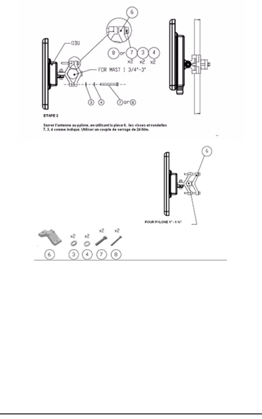
Montage sur un pylône Appendix G
RADWIN 2000 User Manual Release 2.5.40 G-4
Figure G-4: Montage sur un pylône
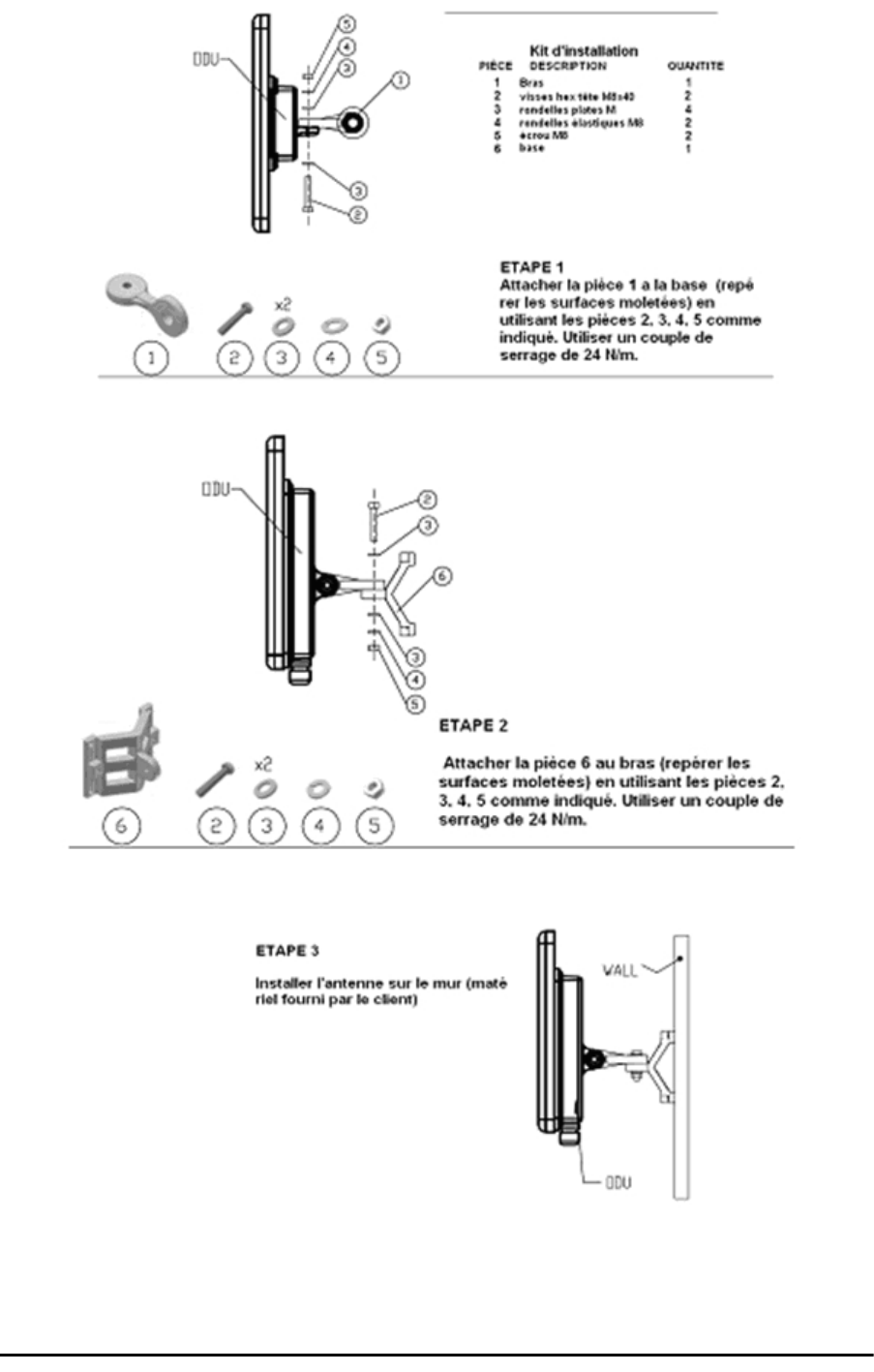
Montage sur un mur Appendix G
RADWIN 2000 User Manual Release 2.5.40 G-5
Montage sur un mur
Figure G-5: Montage sur un mur

Montage d'une antenne externe Appendix G
RADWIN 2000 User Manual Release 2.5.40 G-6
Montage d'une antenne externe
L'antenne externe optionnelle peut être montée sur un pylône.
Contenu du kit de montage d'une antenne externe
Le kit de montage d'une antenne externe comprend les pièces suivantes
•Douze rondelles plates
• Huit rondelles élastiques
• Huit écrous hex
• Quatre boulons
• Un support en U
• Un support à pivotement
• Deux courroies de fixation en métal
Pour installer une antenne externe sur un pylône:
1. Attacher le support en U à l'arrière de l'antenne en utilisant quatre rondelles plates,
quatre rondelles élastiques et quatre écrous hex.
2. Attacher le support à pivotement au support en U en utilisant huit rondelles plates,
quatre rondelles élastiques, quatre écrous hex et quatre boulons.
3. Passer les deux courroies de fixation par les fentes verticales dans le support à pivot-
ement.
4. Attacher l'antenne au pylône en utilisant les deux courroies de fixation .
Ajuster l'inclinaison nécessaire en utilisant l'échelle angulaire et serrer tous les boulons et
écrous à la position requise.

RADWIN 2000 User Manual Release 2.5.40 Index 1
A
AAR 1-6
ACS 5-7, 8-26
aging time, ODU Bridge Mode 8-16
Air Interface 1-13, 1-13
Technical Specifications, general A-1
Alarms
Active
summary 9-17
Connector B-3
External , specification E-1
Antennas
Air rates 5-11
Align with beeper 3-13
Aligning 3-13
bipolar 3-13
Buzzer signals 3-14
monopolar 3-14
Cable, grounding 18-1
Connecting 3-13
Described 1-12
Diversity Mode 5-10
External 1-13
Mounting 3-7
Package Contents 3-5
External, Mounting 17-4
MIMO - Diversity settings 5-11
MIMO Mode 5-10
Single and dual 5-9
types 1-9
Applications
Broadband Access 1-4, 1-4
Cellular Backhaul 1-4
Private Networks 1-5
WiMAX 1-4
Asymmetric Ethernet
and Collocation 5-19
and TDM services 5-20
Installation 5-18
Restrictions 5-19
Transmission ratio 5-18, 6-5
Automatic Adaptive Rate, see AAR 1-6
Automatic Channel Selection, see ACS
Automatic Repeat Request 1-6
B
Backup 8-24
backup
ODU replacement 9-20
Backup and restore software, ODU 8-24
Band
and DFS 20-5
available 1-9
Changing 20-1
defaults 1-9, 20-3
license key 1-9
Beeper
mute 8-25
muting and restoring 8-2
restore 8-25
Bridge mode,Telnet commands 8-26
BRS 1-2, 1-3
C
Changing link password 5-5
Channel, selecting 5-7
Clock configuration, TDM 5-27
Community Strings
Changing 8-10
Editing 8-10
Forgotten passwords 8-10
MIB D-2
Read-Only 8-9
Read-Write 8-9
Trap 8-9
Configuration Parameters 8-3
Configuring
Advanced 8-2, 8-15, 8-17, 8-19
Air Interface 8-2
Air interface 7-1
contact person 8-2
Date and Time 8-2
Date and time 8-1
Ethernet settings 8-1
External alarms 8-1
Frequency channel 7-1
Index

RADWIN 2000 User Manual Release2.5.40 Index 2
HSS 8-1
Security 8-2
Security settings 8-1
Service parameters 7-1
System 8-2
System parameters 7-1
System settings 8-1
TDM MHS status 8-1
Tx Power and antenna 8-1
View Inventory 8-2
Connecting user equipment 5-7
Customer Support 9-21
D
Date and time, setting 8-2, 8-13
DC Power
terminal pinout B-4
DFS 16-1
changing band for 20-5
Configuration 16-4
Link Activation 16-1
E
Ethernet Ring 13-1
1 + 1 13-6
operation 13-2
Protection Switching 13-6
purpose 13-1
setting up, ff 13-7
supported topologies 13-4
terminology 13-1
Events
color codes 9-16
log 9-2, 9-9
priority 9-16
F
Factory settings
revert to 8-1, 8-22, 9-21
FCC/IC DFS Installation Procedure 16-1
FEC 5-10, 5-11, A-1, A-1
Forward Error Correction, see FEC
G
Gateway 8-2
Telnet display 8-26
GSU A-6
Cascaded Sites 11-3
Configuring 11-5
Installation 11-4
Kit 11-4
Preferences 11-12
Redundancy 11-3
Software Update 11-13
Telnet Support 11-12
Transmission Phase 11-3, 11-9
Tx Transmission Ratio 11-9
use functionality
scenarios 11-1
GUSand RFP 11-8
H
HSS 10-1
and asymmetric allocation 10-11
and asymmetric allocation<$endtrange 5-19
Hardware Installation 10-3
IDU-C front panel LEDs 3-11, 10-12
ODU/HSS Connection Pinout 10-7, B-1
Radio Frame Pattern Table 10-7
HSS Client 10-2
Continue Transmission 10-3
Disable Transmission 10-3
HSS Master 10-2
Hub Site Synchronization, see HSS
I
IDUAging time 8-16
aging time, ODU Bridge Mode 8-16
Connecting to ODU 3-11
described 1-9
IDU-C
Alarm Connector B-3
Front panel 1-10, 1-11
Described 3-9
LEDs 3-9, 3-10, 4-3
Front panel LEDs for HSS
LEDs 3-11, 10-12
Mounting 3-9
Power connections 3-11, 3-11
Installing IDU-E and R units 3-8
Package Contents 3-4
IDU-C
Package Contents 3-4
IDU-E or IDU-R package contents 3-4
Indoor Unit, see IDU
Installation
Menu and Toolbar Functionality 6-3
Post Configuration main window 7-13
Post Installation main window 5-30
see Link, Installation
Installation Mode 8-2, 8-2, 8-17
Interference
caused by collocated units 10-2
Inventory 8-1, 8-10
Displaying 8-8
IP address 8-2
Telnet display 8-26

RADWIN 2000 User Manual Release2.5.40 Index 3
J
Jitter Buffer 5-23
K
Key Features of Radio Link
Advanced Air Interface 1-6
Air Interface 1-6
Capacity 1-5
Combo Frequency Products 1-6
E1/T1 + Ethernet in one Solution 1-5
Installation and management 1-7
Multi-band Products 1-6
Range performance 1-6
Security 1-7
SFP support 1-8
Spectral Efficiency 1-5
Transmission (Tx) power 1-6
L
LBC 9-8
Browser warnings 21-6
Calculations 21-2
Climactic C Factors 21-11
described 21-1
Fresnel Zone, described 21-3
Internal data 21-1
Running 21-5
User input 21-1
License key
band 1-9
License Key, entering 20-5
Lightning and Grounding Guidelines 18-1
LinkBudget Calculator, see LBC
Configuration
Step 1 - Start the Wizard 7-3
Step 2 - System Parameters 7-3
Step 3 - Channel Settings 7-4
Step 4 - Tx Power and Antenna Settings
7-8
Step 5 - Hub Site Synchronization Settings
7-10
Step 6 - Services 7-10
Step 7 - TDM Clock Configuration 7-11
Step 8 - Configuration Summary and Exit
7-12
default frequency 5-7
default Settings 4-11
Information 9-1
Air Interface Thresholds
BBER Threshold 9-13
Ethernet Thresholds - Capacity 9-13
Ethernet Thresholds - Traffic 9-13
RSL Threshold 9-13
TSL THreshold 9-13
Air Interface Thresholds, setting 9-12
Alarms
Active summary 9-17
Error detection and 9-17
output 9-19
saved 9-17
Compatibility 9-3
Trap messages 9-3
Events Log 9-8
Events log 9-13
Events references
trapbackground color 9-16
default colors 9-17
Preferences 9-16
saving 9-17
Monitor log 9-8, 9-9
saving 9-9
Performance data, explained 9-11
Performance monitoring 9-8
Performance Reports 9-9
Remote Power Fail Indication 9-19
“Dying-Gasp” circuit 9-19
Throughput Checking 9-8
Troubleshooting 9-19
Installation 4-9
ODU
Mast and Wall 17-1
Step 1 - Start Wizard 5-3
Step 2 - System Parameters 5-3
Step 3 - Channel Settings 5-7
Step 4 - Tx Power and Antenna Settings
Background 5-9
Step 4 - Tx Power and Antennas
Settings 5-9
Step 5 - Hub Site Synchronization Settings
5-16
Step 6 - Services 5-16
Step 7 - TDM Clock Configuration 5-27
Link ID 4-11, 5-4, 8-26, 9-19, 9-20, 9-20
Login 4-3
Login Errors
Incorrect IP Address 4-7
Incorrect password 4-7
Unsupported Device 4-6
Login showing Community Options 4-4
Login showing user types 4-5
Manager Software 4-2
Name 5-4
Password 1-8, 9-20
changing 5-5
Post Configuration main window 7-13
Post Installation main window 5-30
Site names 5-4
Link Budget Calculator, see LBC 9-8
Link ID 4-11, 5-4, 8-26, 9-19, 9-20, 9-20
Link Lock
described 8-11

RADWIN 2000 User Manual Release2.5.40 Index 4
Enable 8-11
Link Site
Planning 2-1
Survey 2-1
Stage 1 - Preliminary Survey 2-2
Stage 2 - Physical Survey 2-3
Additional Indoor Site Requirements
2-3
Additional Outdoor Site Requirements
2-3
Stage 3 - RF Survey 2-4
Login Errors
Incorrect IP Address 4-7
Incorrect password 4-7
Unsupported Device 4-6
loopback
activating 9-3
deactivate 9-5
Local Internal 9-7
Remote External 9-6
Remote Internal 9-6
M
Management
Addresses 8-5
and trap addresses 8-1
Configuring the Site 8-2
Screen, Telnet 8-27
Manager Software
Change log on password 4-8
Events Log 6-6
Installing 4-1
Main window 6-1
Details pane 6-4
Toolbar 6-2
main window 4-6
Monitor pane 6-5
Ethernet Service
6-5
Radio Interface, 6-5
Radio signal strength 6-5
Off-line functionality 4-8
Status Bar 6-7
Manual
Chapters by Audience 1-15
Terminology 1-16
MHS
described 12-1
Installation Procedure 12-1, 12-1
Installing 12-3
Kit Contents 12-3
Maintaining 12-9
IDU Replacement 12-9
ODU Replacement 12-10
Port pinout B-2
Primary and secondary links 12-2
provides 12-2
Switching Logic 12-10
System Operation 12-14
MIBAbout D-1
Community String D-2
Interface API D-1
Parameters D-3
Private D-2
Private Parameters D-6
Reference D-1
Supported Variables from the RFC 1213 D-4
TDM D-3
Terminology D-1
Traps D-23
Monitored Hot Standby, see MHS
O
ODU 1-9
Available products 1-9
Backup and restore software 8-24
Bridge Mode
aging time 8-16
Connectorized 1-9
Connectorized Antenna 1-8
described 1-8, 1-8
form factors 1-9
Installation, Mast and Wall 17-1
Integrated Antenna 1-8, 1-9
Mounting Kit 17-1
Package Contents 3-2
Preloading IP address 19-1
Products 1-9
Replacing 9-20
With integrated antenna 1-13
P
Package, contents of 3-2
Password
Link 1-8, 9-20
PC, Minimum Requirements 4-1
Performance
Monitor 9-2
Performance Monitoring, set time interval 9-9
PoEBasic PoE Device 1-11
Described 1-11
Installing a link using 3-12
PoE device, see PoE
Power over Ethernet, see PoE
Protection
External Lightning Surge Suppressors 18-3
Grounding
Antenna cable 18-1
IDUs 18-2
ODUs 18-2
Internal ESD Protection circuits 18-8

RADWIN 2000 User Manual Release2.5.40 Index 5
Q
QoS 25-1
disabling 25-4
Overview 25-1
setting up, ff 25-2
R
Radio Frame Pattern (RFP)
General Considerations 10-8
General considerations 10-8
With HSS 10-7
Without HSS 10-7
Radio Link
Additional Tools and Materials Required 3-5
Air rates 5-11
Connecting user equipment 3-12
Hardware Installation
External Antennas 3-7
Indoor 3-8
Lightning protection 3-8
Mounting U 3-9
ODU 3-7
Outdoor 3-7
Outdoor connections 3-8
Sequence 3-6
Package Contents 3-2
IDU 3-4
ODU 3-2
Package contents
External Antennas 3-5
Radio Outdoor Unit, see ODU
Regional Notice
French Canadian G-1
Replacing an ODU 9-20
S
Safety Practices iii-iv, 3-1
Grounding 3-1
Preventing overexposure to RF energy 3-1
Security
Link Lock 8-11
Selecting channel 5-7
SFPdevice C-1
support, described C-1
SiteConfiguration
Backup Files
backup to 8-24
Backup files
restore from 8-24
Configuration with Telnet 8-25
Dialog
Change Tx Power 8-3
Ethernet Properties 8-15
Configuring
Bridge 8-15
Maximum information rate 8-19
Ports Mode 8-17
Ethernet PropertiesIDU Aging time 8-
16
Functions 8-2
Inventory 8-8
Menu bar 8-2
Setting the date and time 8-13
View Air Iinterface details 8-3
VLAN Settings 8-6
Lost or forgotten VLAN ID 8-7
Priority number 8-7
VLAN ID 8-7
External Alarm Inputs 8-21
Reset site 8-22
Reset site to factory defaults 8-22
Reset site, preserve current configuration
8-22
Security Features 8-9
Community Strings 8-9
Editing 8-10
Forgotten paswwords 8-10
Initial log on defaults 8-10
Default Gateway 8-6
IP address 8-6, 8-6
Trap Destination 8-6
Software Upgarde
Multiple sites 15-3
Single Site 15-2
Software Upgrade 15-1
Spectrum View
described 4-11
using 23-1
T
TDM Services
Clock configuration 5-27
Evaluation 5-26
in Link Budget calculation 21-1
Jitter Buffer 5-23
Loopbacks 9-3
modulation rate 5-23
over internet with SFP C-1
selection 5-20
TDD in MIB D-3
Telnet commands 8-26
Throughput display 6-6
Trap message 9-15
Technical Specifications
Air Interface, general A-1
Configuration A-1
EMC A-3, A-5, A-5, A-6, A-7
Environmental A-3, A-4
Mechanical A-2
Power A-2, A-3, A-4, A-4, A-4, A-4, A-4, A-4
Radio A-1

RADWIN 2000 User Manual Release2.5.40 Index 6
Safety A-3, A-4
Telnet configuration 8-25
TDM 8-26
Time Division Duplex 10-7
Trap messages 9-3
Trunk Ports
pinout B-2
typical installation 3-6
U
User equipment, connecting 5-7
V
VLAN
configuration 14-5
Port Functionality 14-2
QinQ 14-2
tagging 14-1
terminology 14-1
VLAN for Ethernet services 8-17
VLAN for Ethernet services, ff 13-1, 14-1, 25-1
W
Wiring Specifications B-1
Alarm
Connector
IDU-C B-3
Connectors
User Port B-2
LANPorts B-2
ODU-IDU Cable B-1
Ports
LAN B-2
User Port Connectors B-2