Radwin RW2030 Outdoor radio unit operating in 3.65 GHz band User Manual STW
Radwin Ltd. Outdoor radio unit operating in 3.65 GHz band STW
UserManual.wiki
>
Radwin
>
RW2030 User Manual
>
Manual part 1
Contents
1.
Manual part 1
2.
Manual part 2
3.
Users manual part 1
4.
Users manual part 2
5.
Revised User manual part 2
6.
Revised User manual part 1
Manual part 1
Navigation menu
Upload a User Manual
Namespaces
Wiki Guide
HTML
PDF
Info
Views
User Manual
Discussion / Help
Navigation


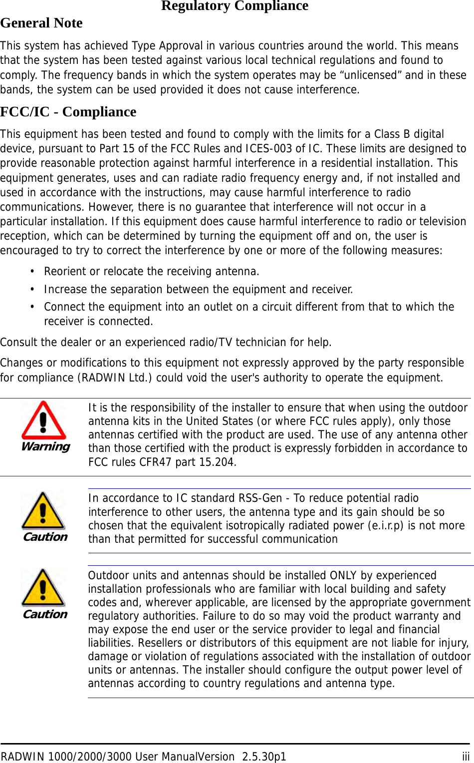
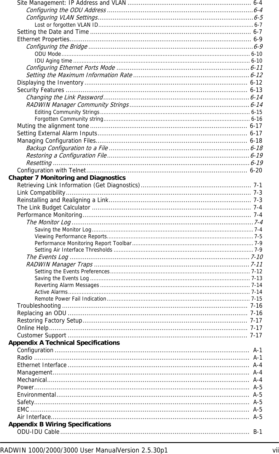
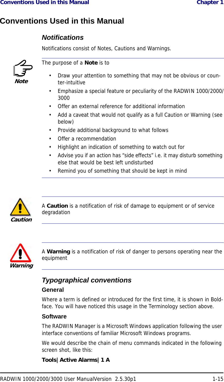
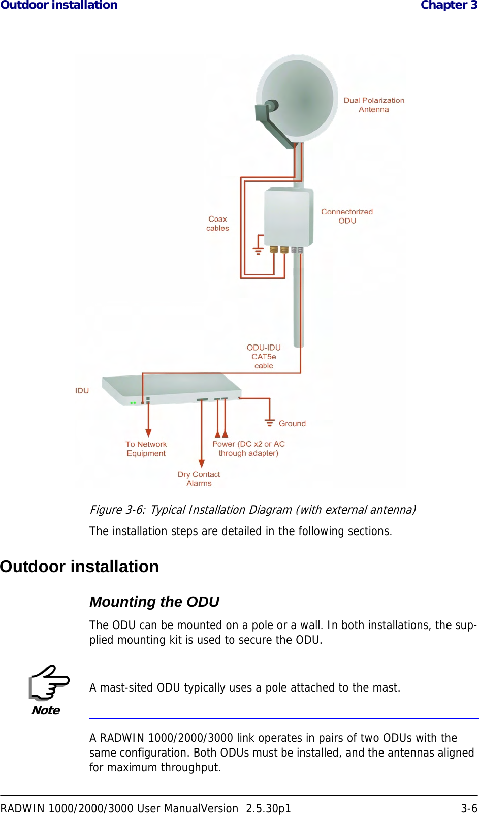
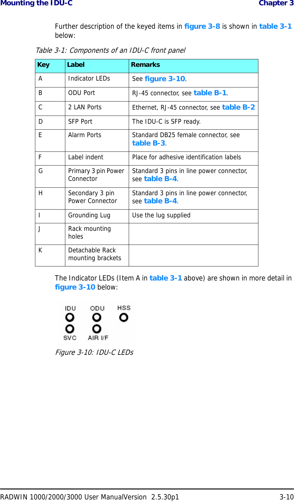
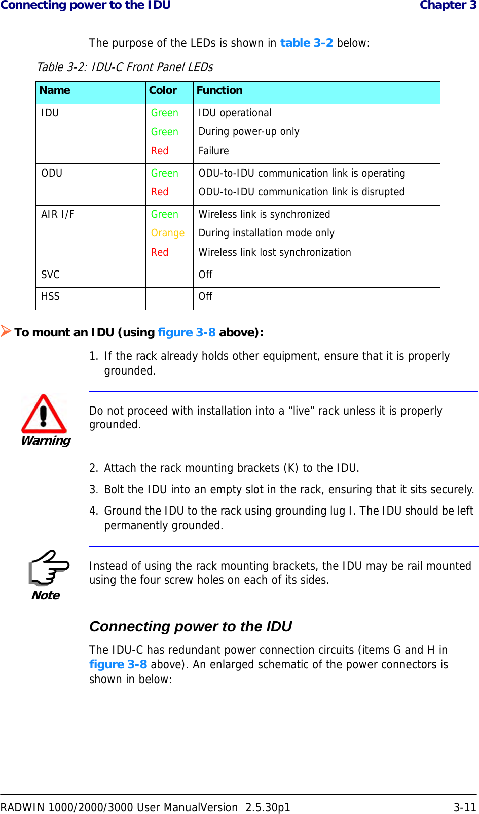
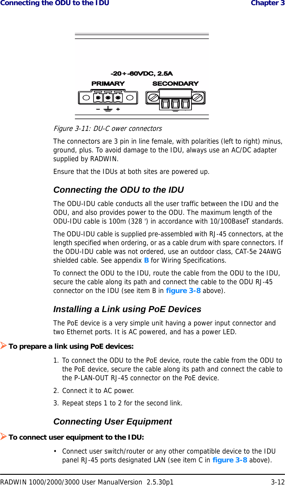
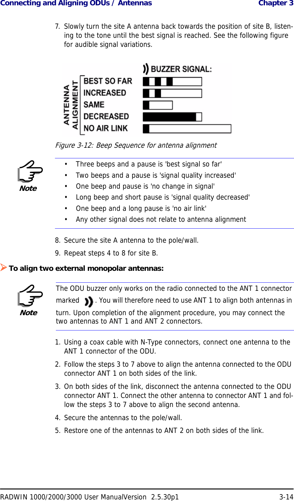
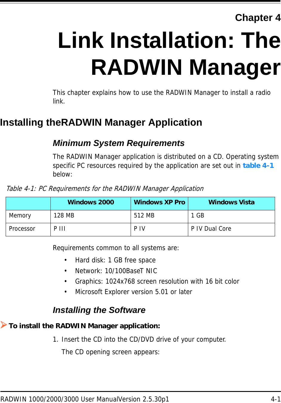
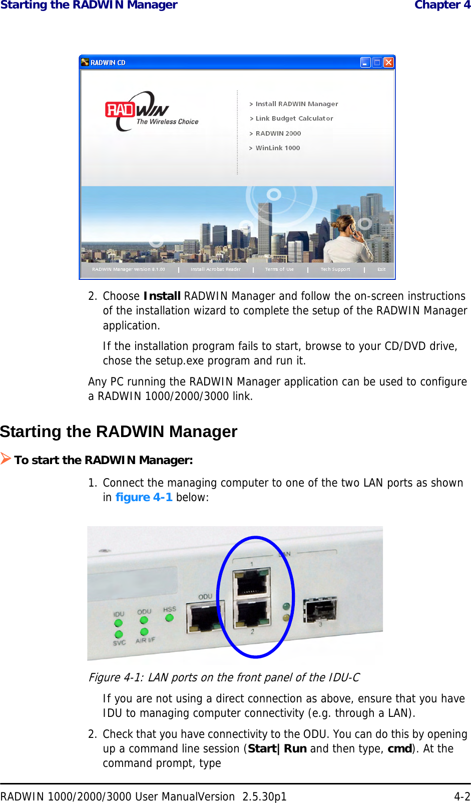
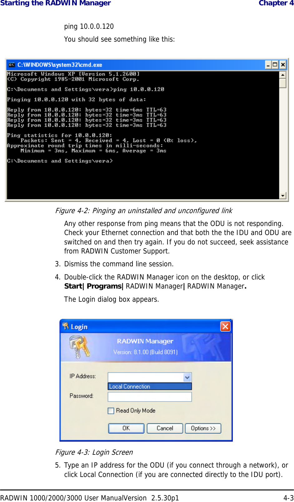
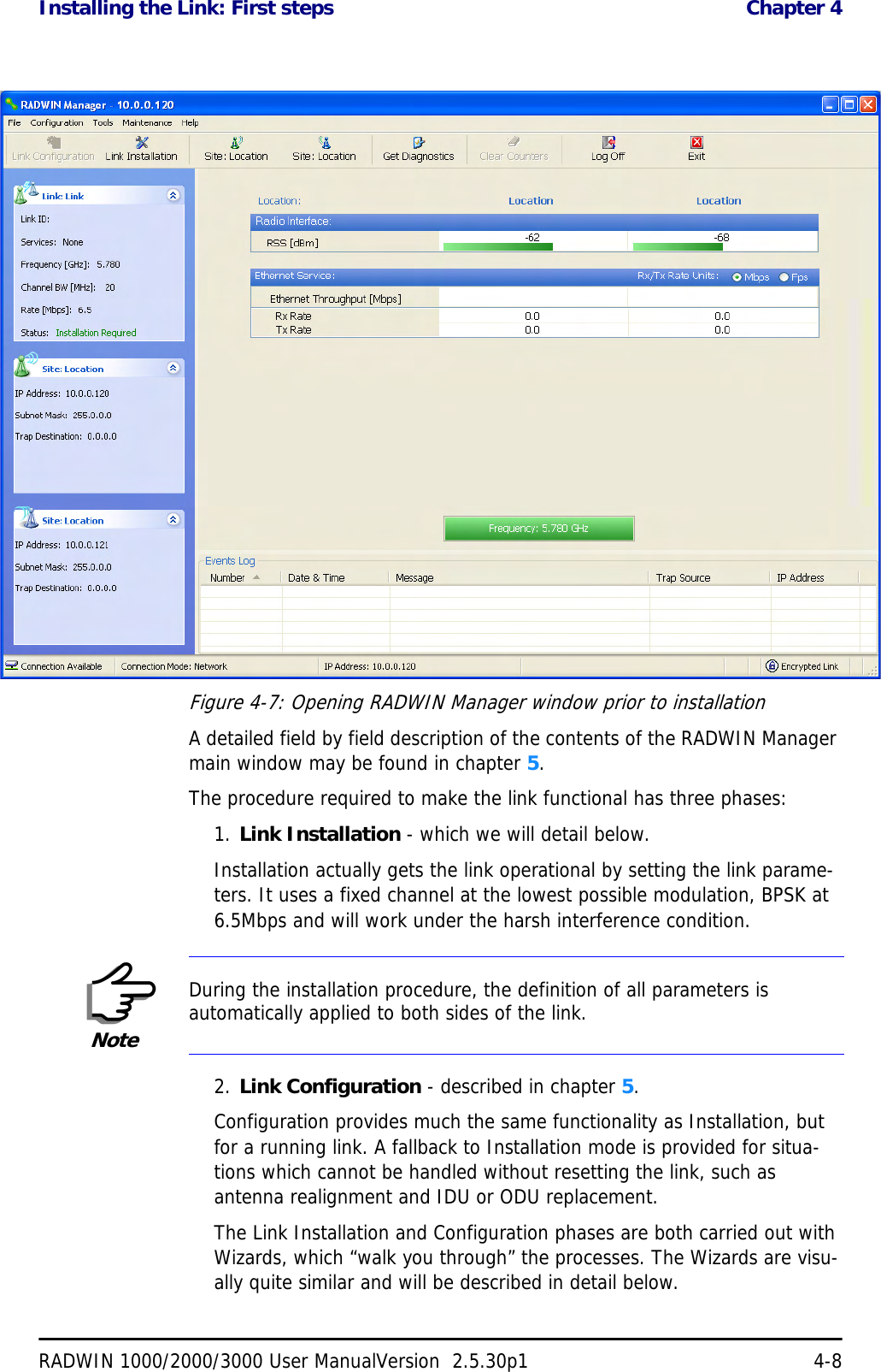
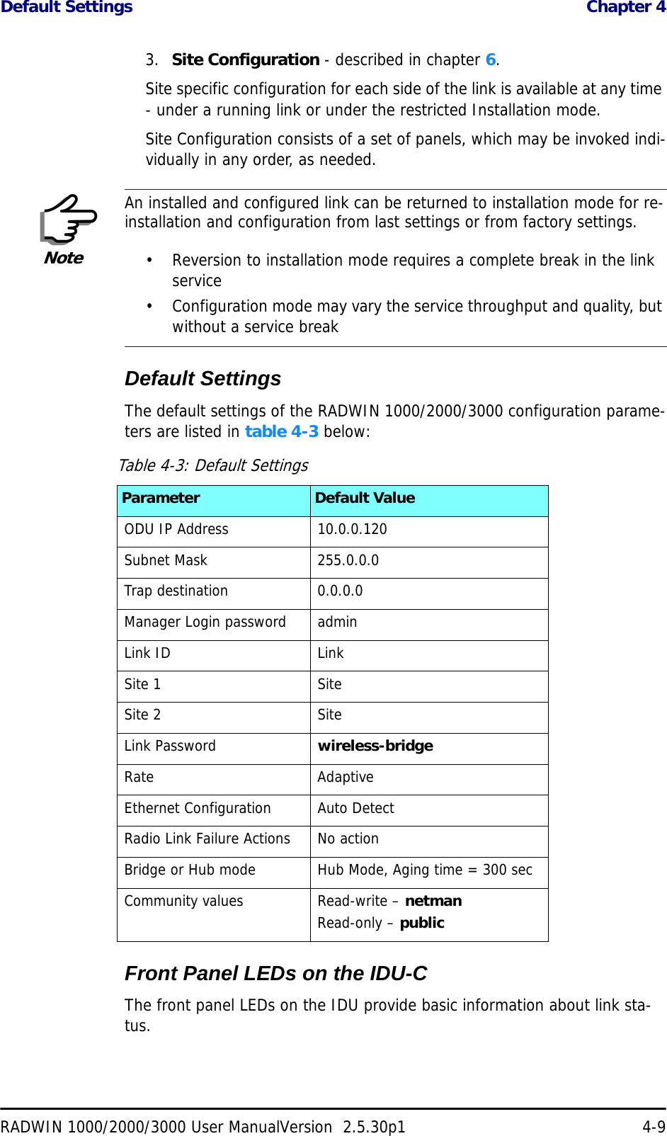
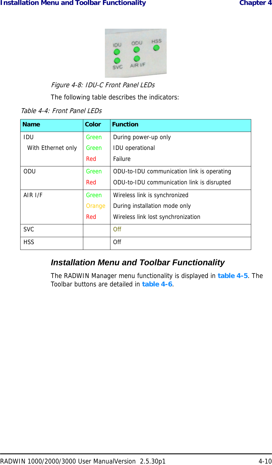
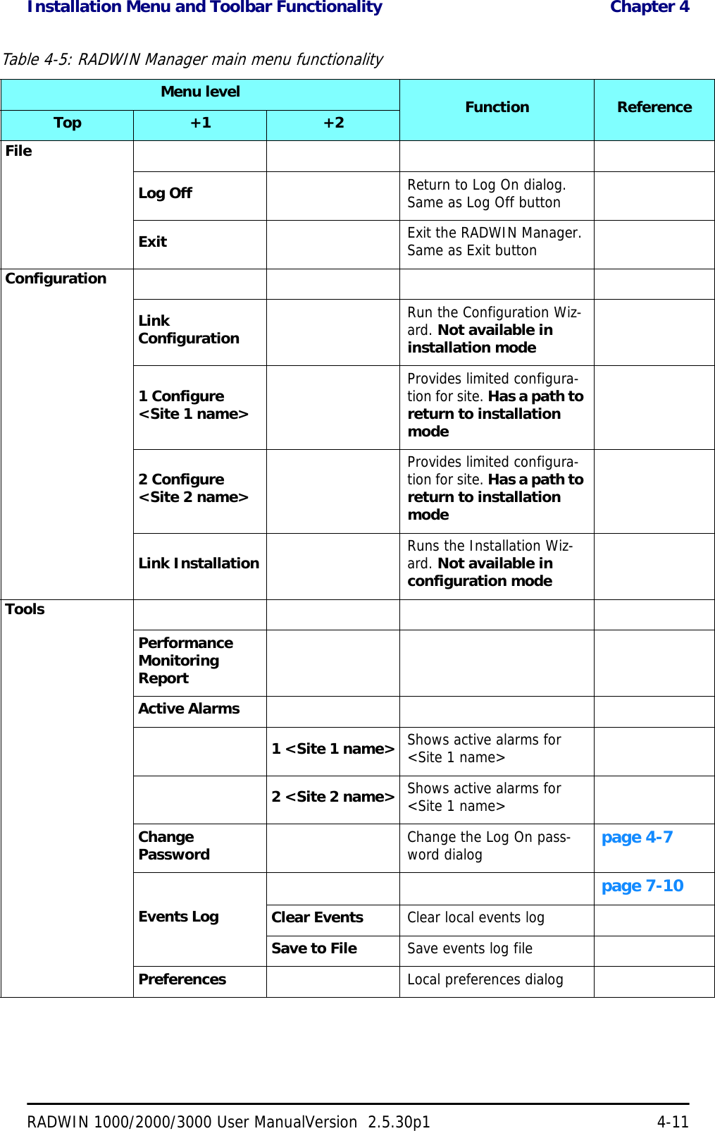
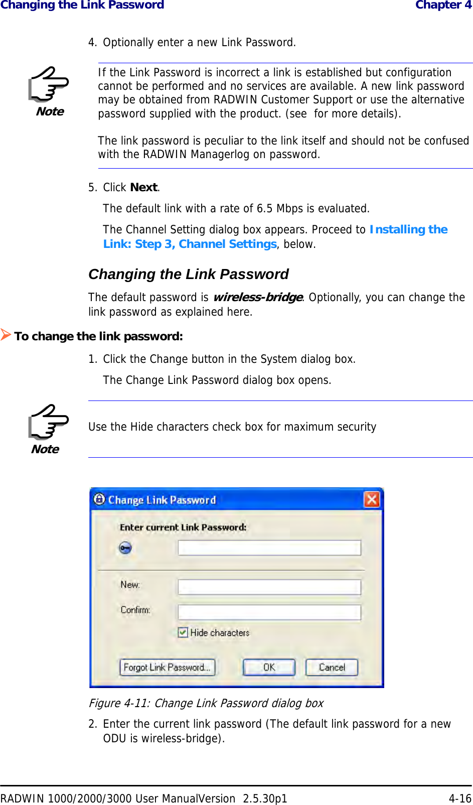
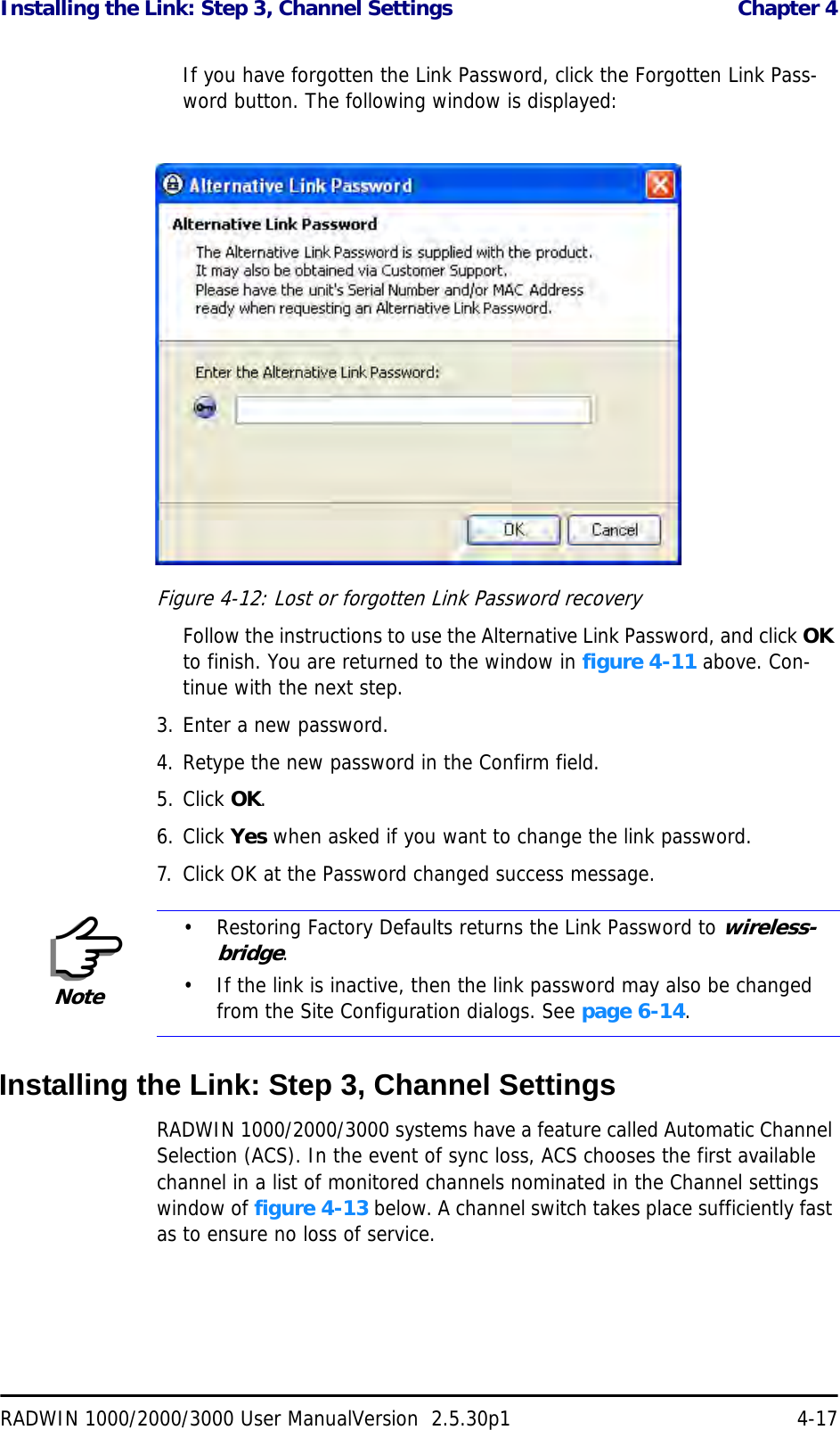
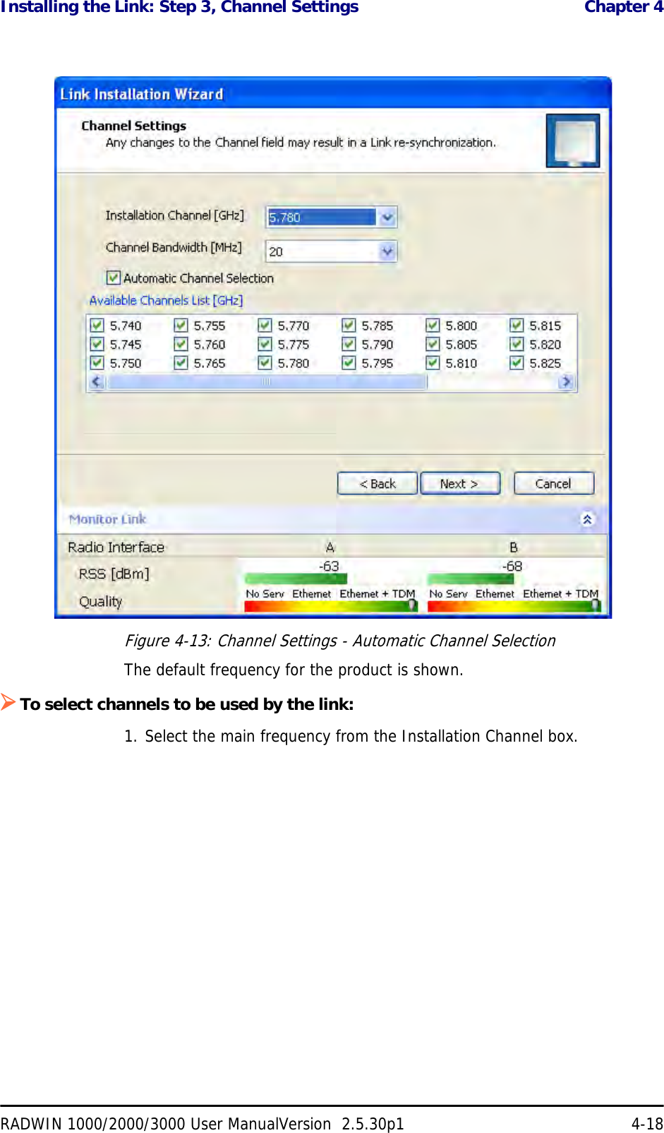
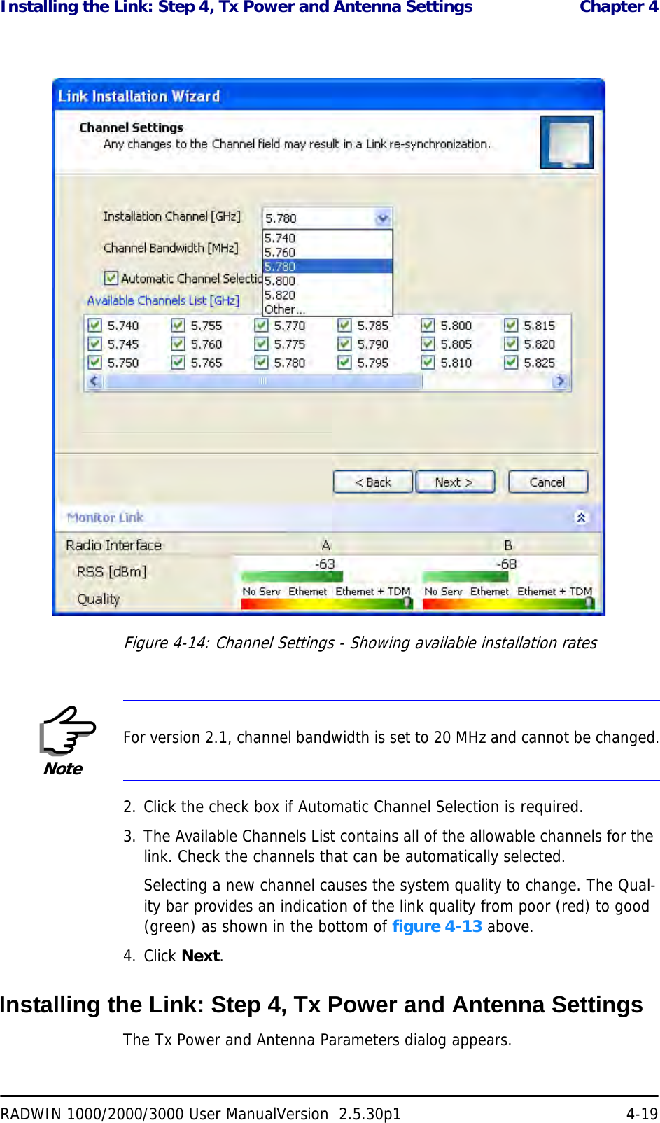
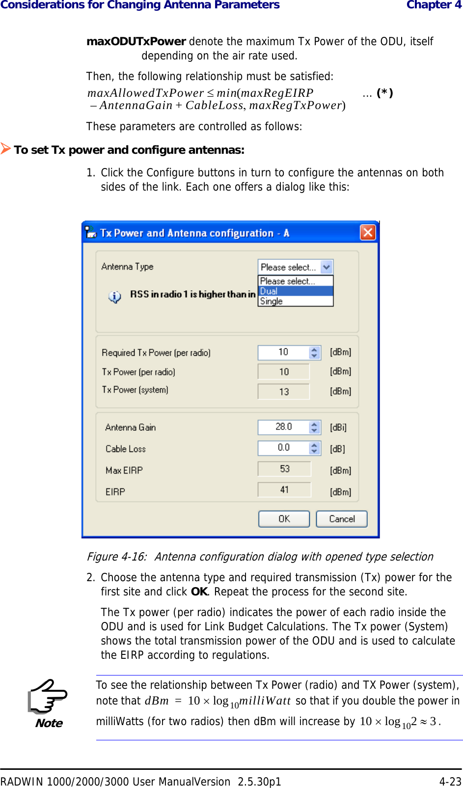
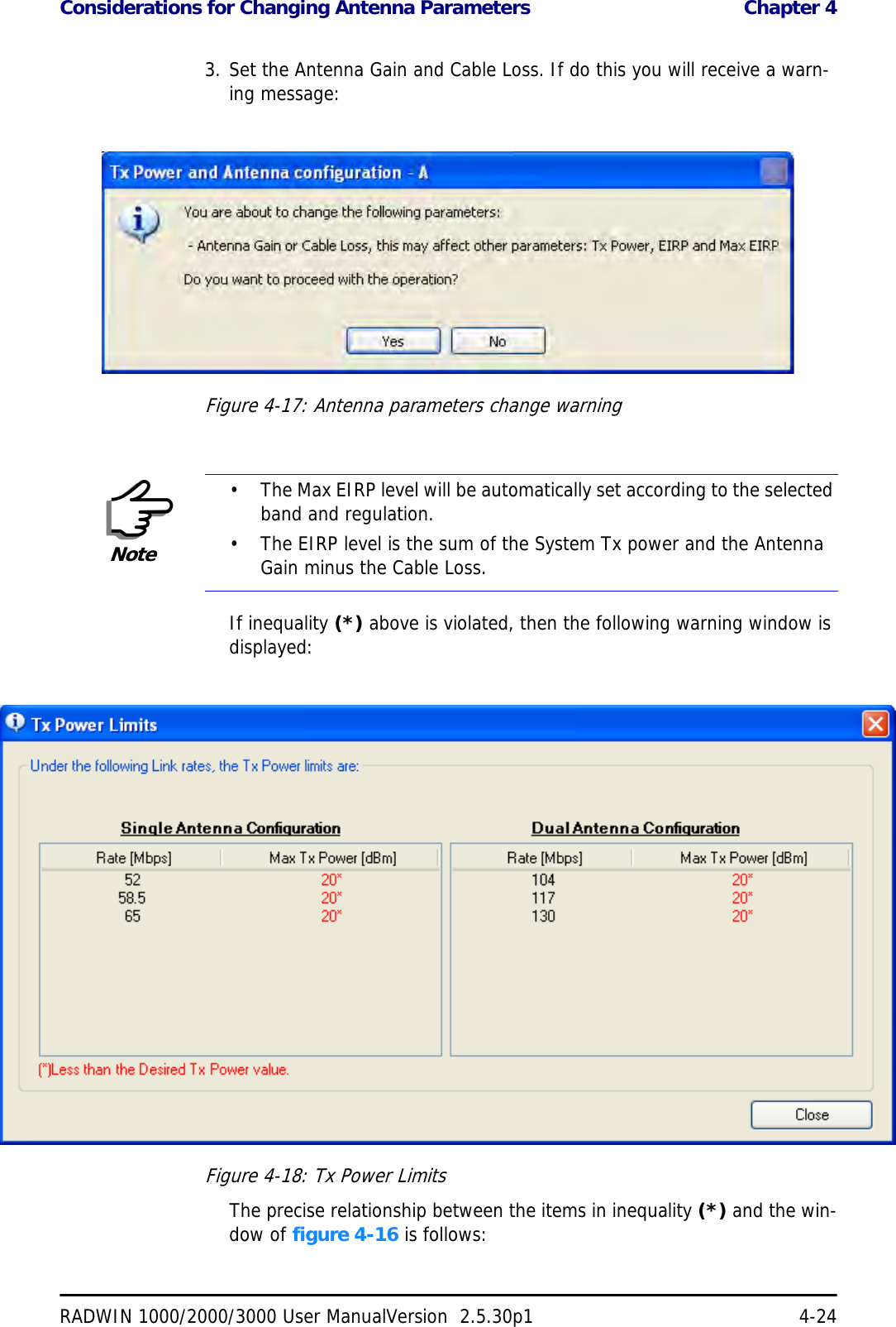
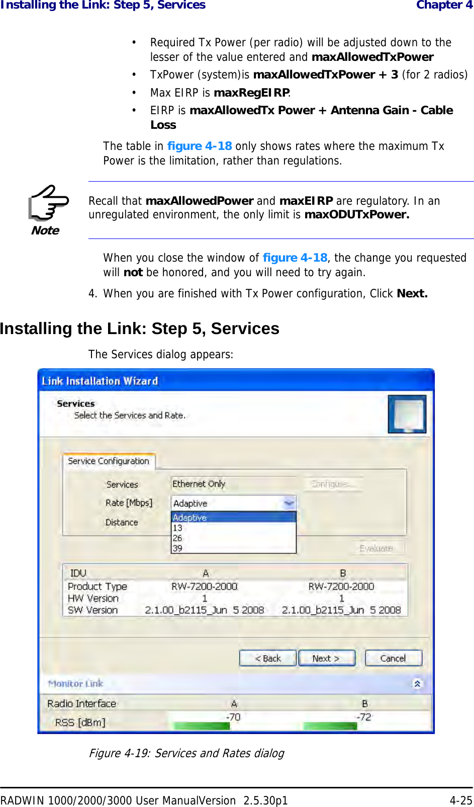
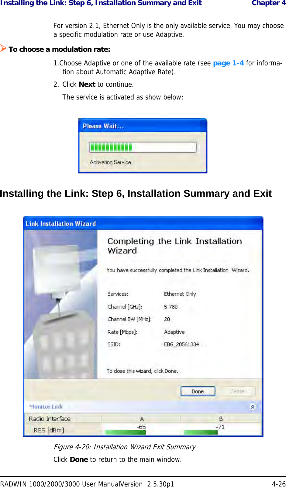
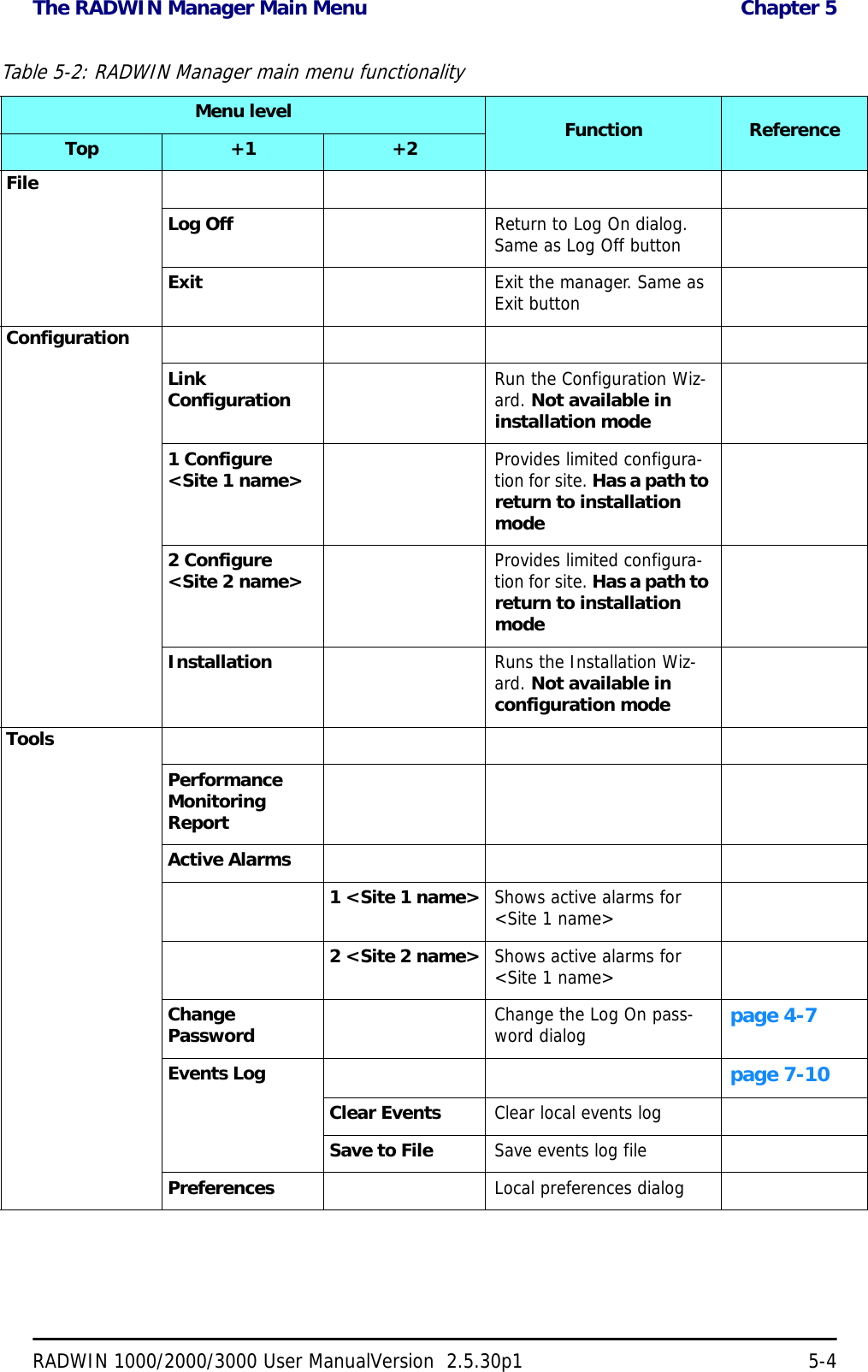
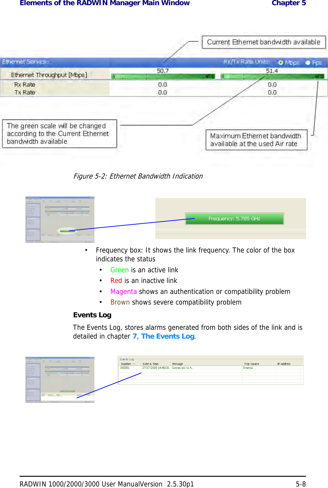
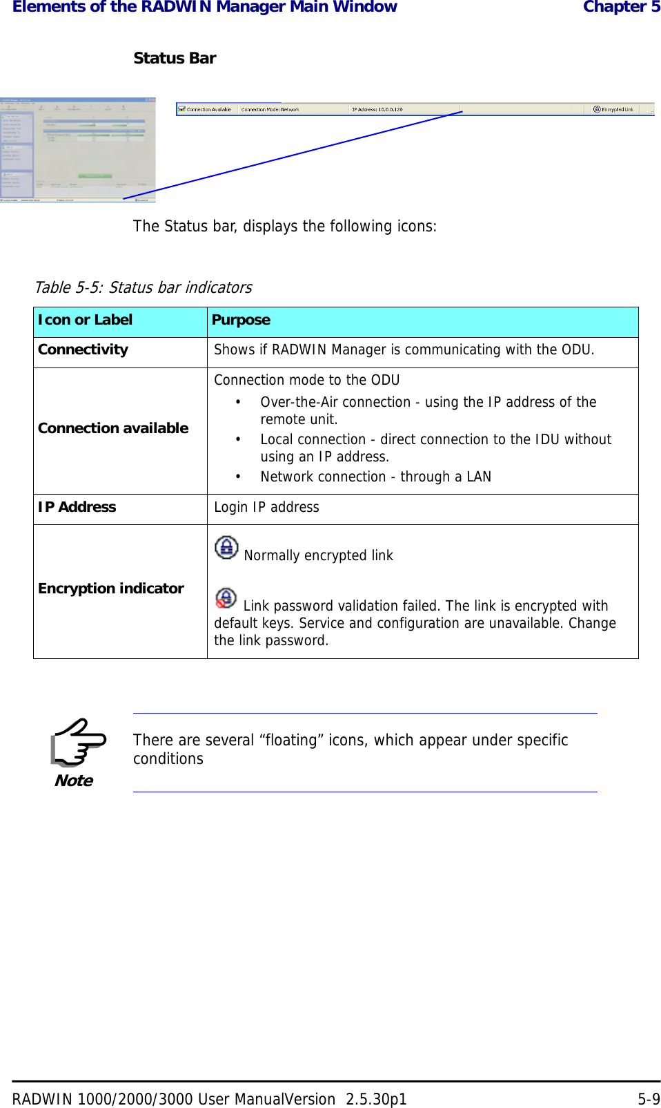
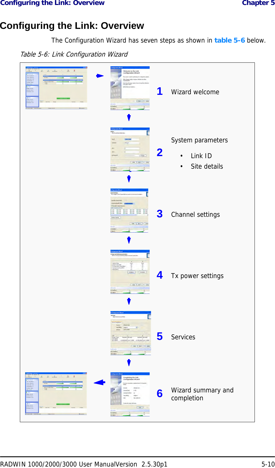
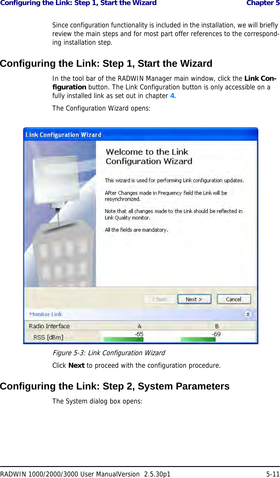
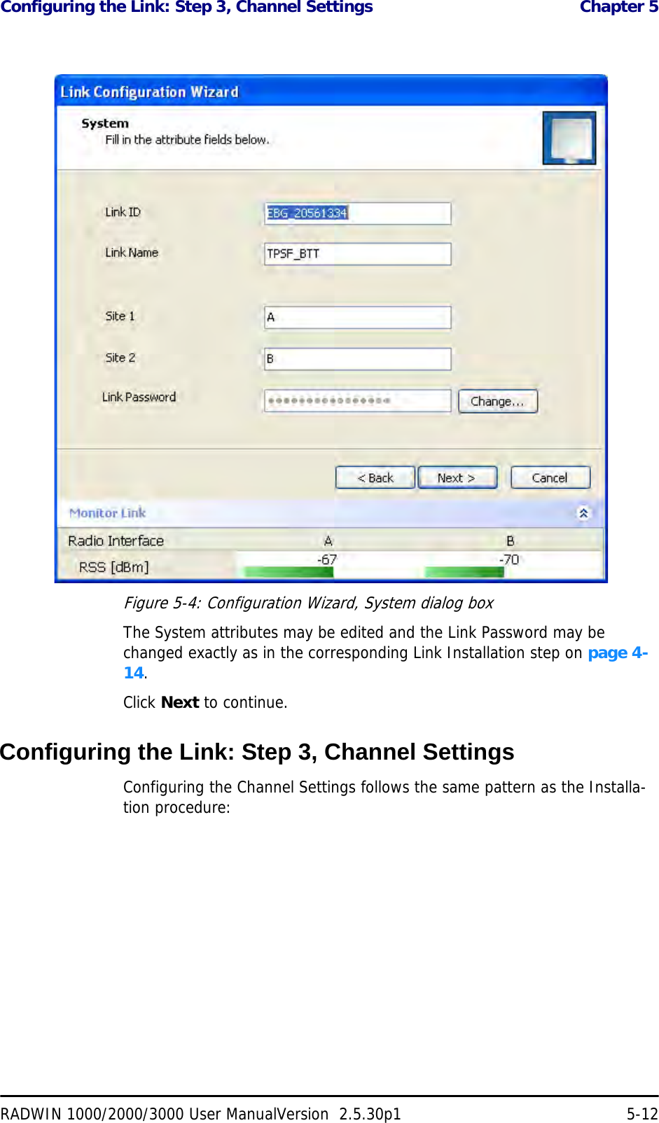
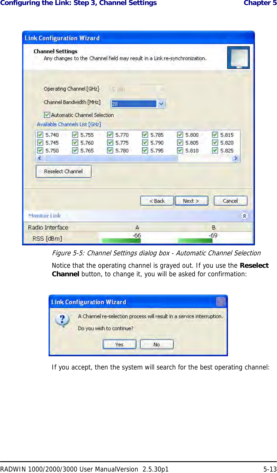
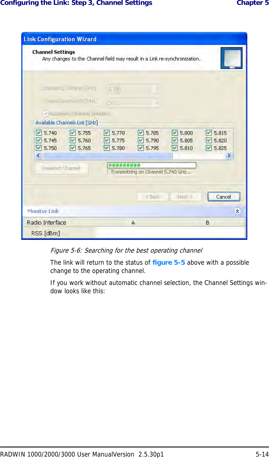
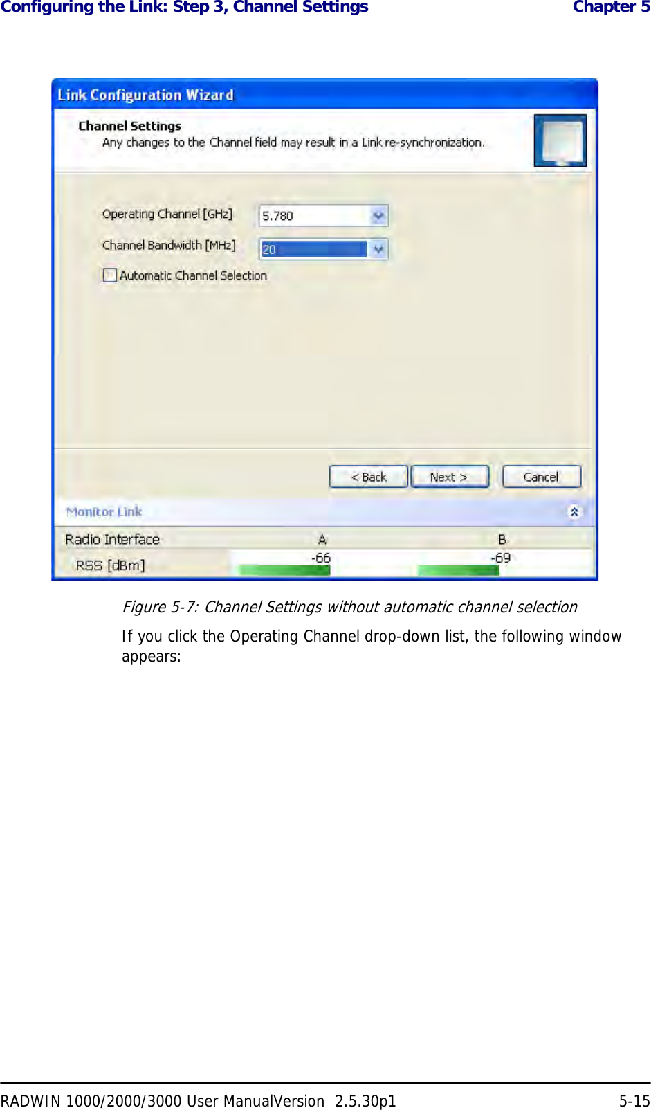
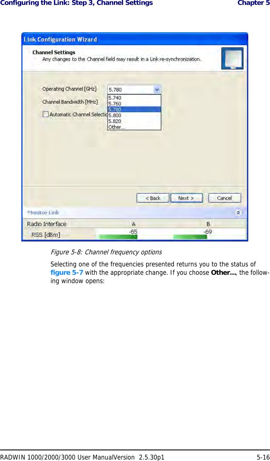
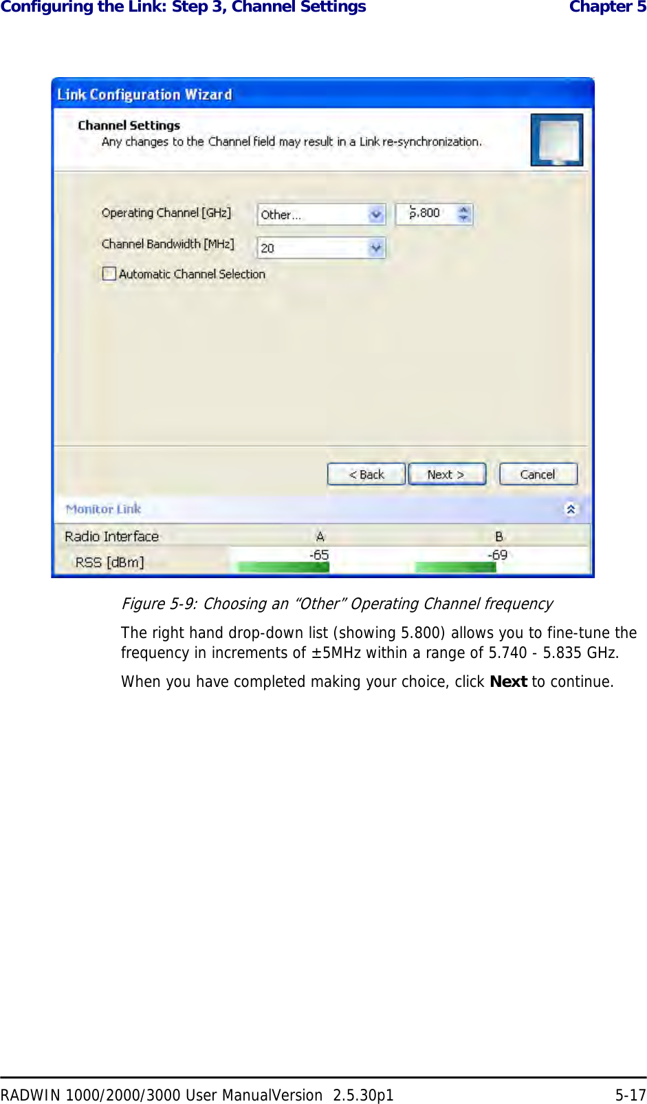
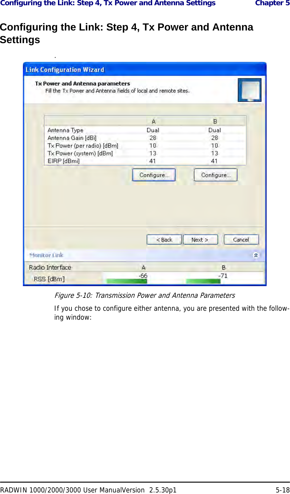
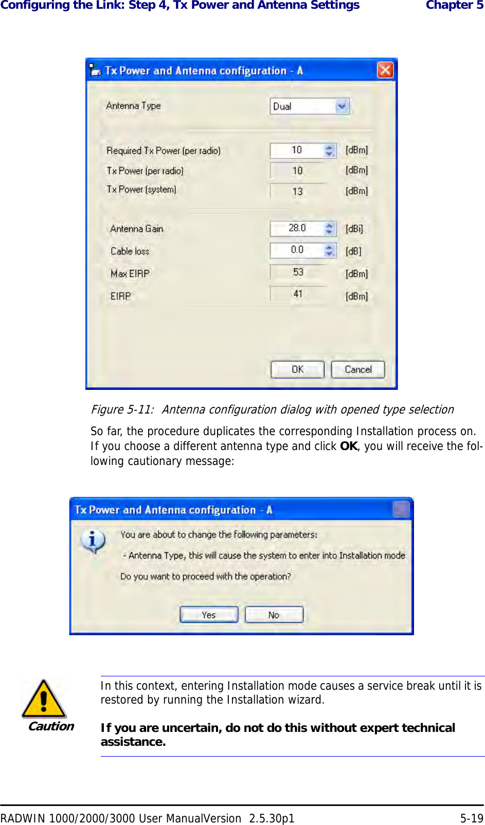
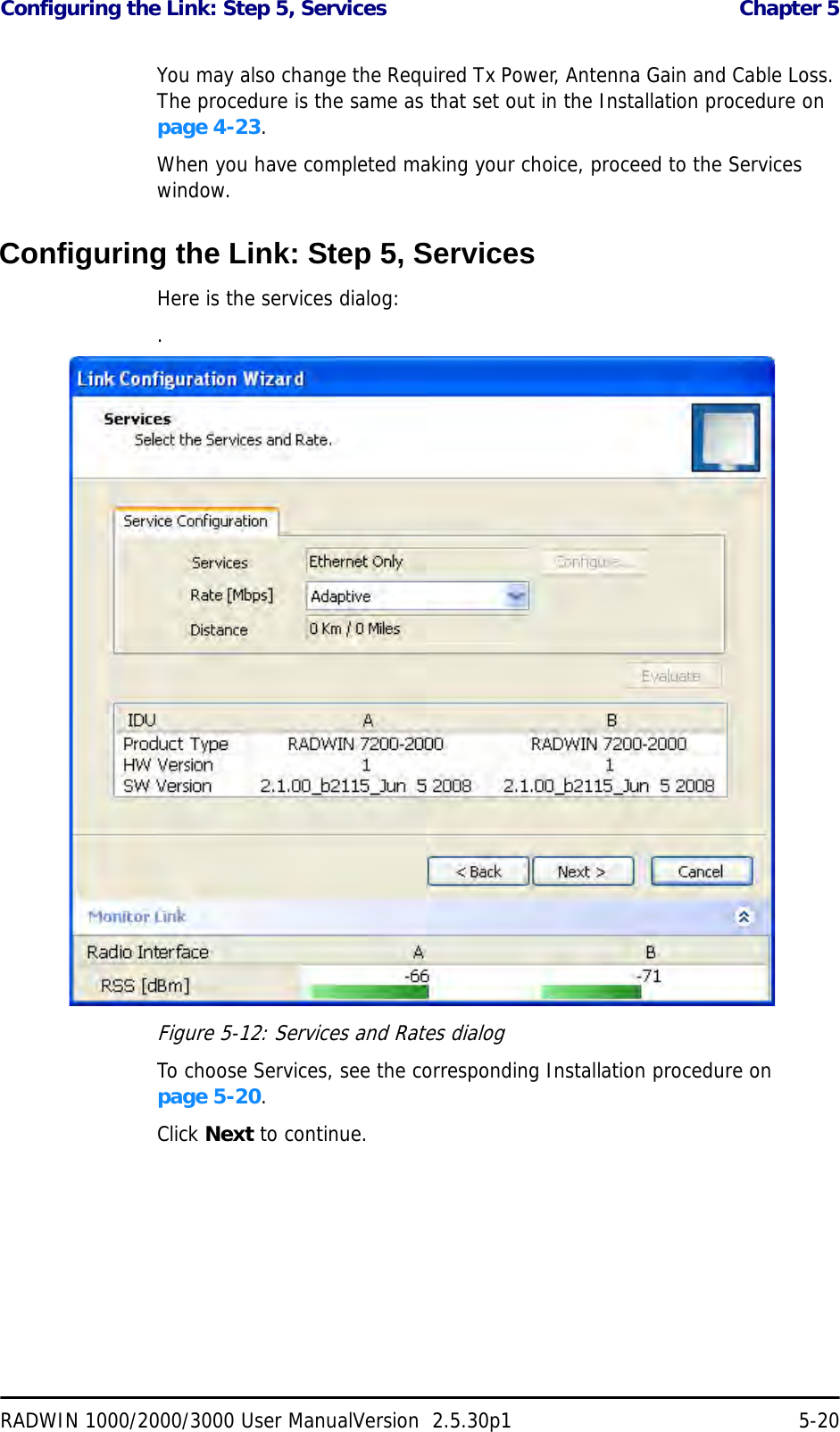
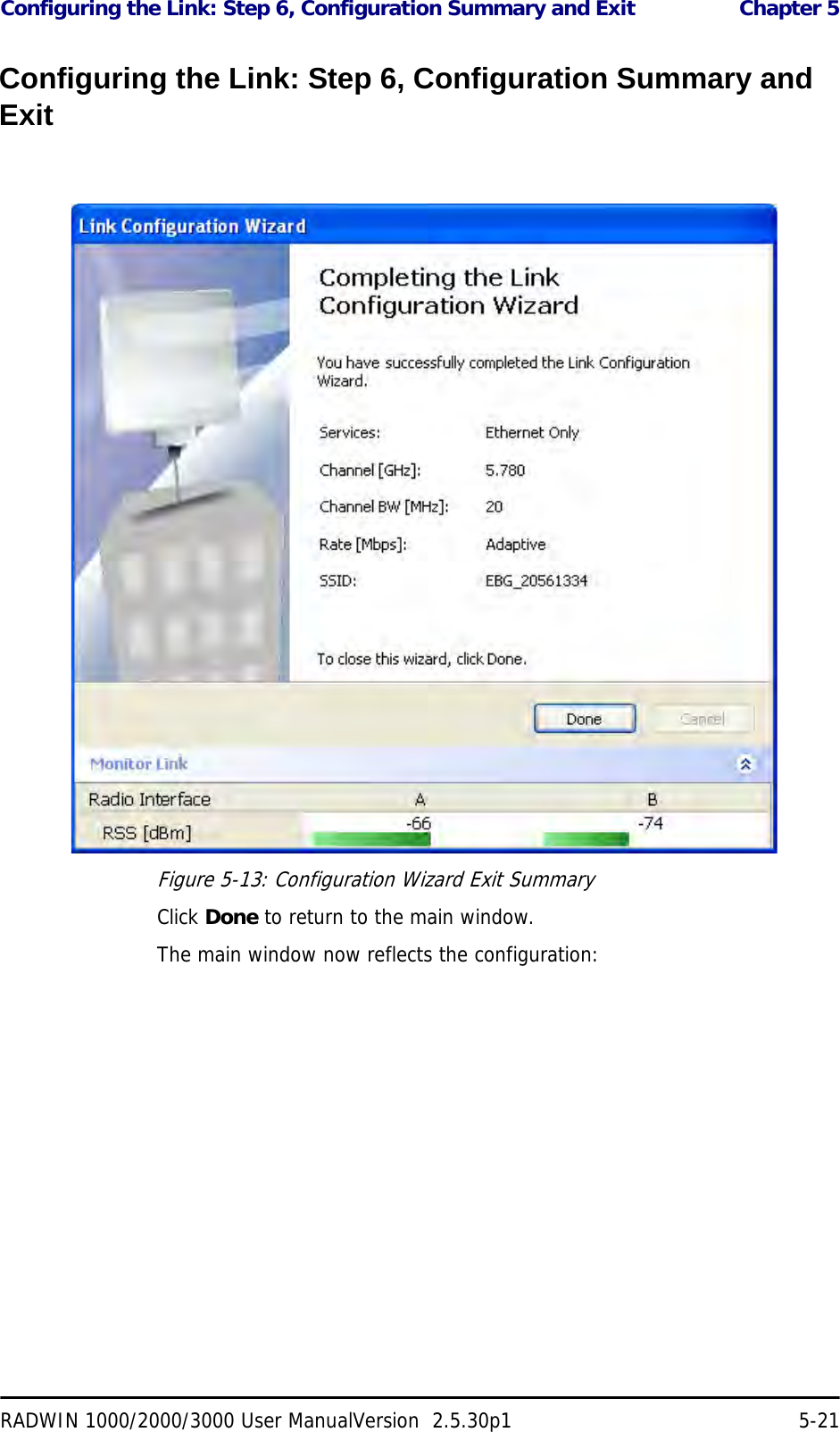
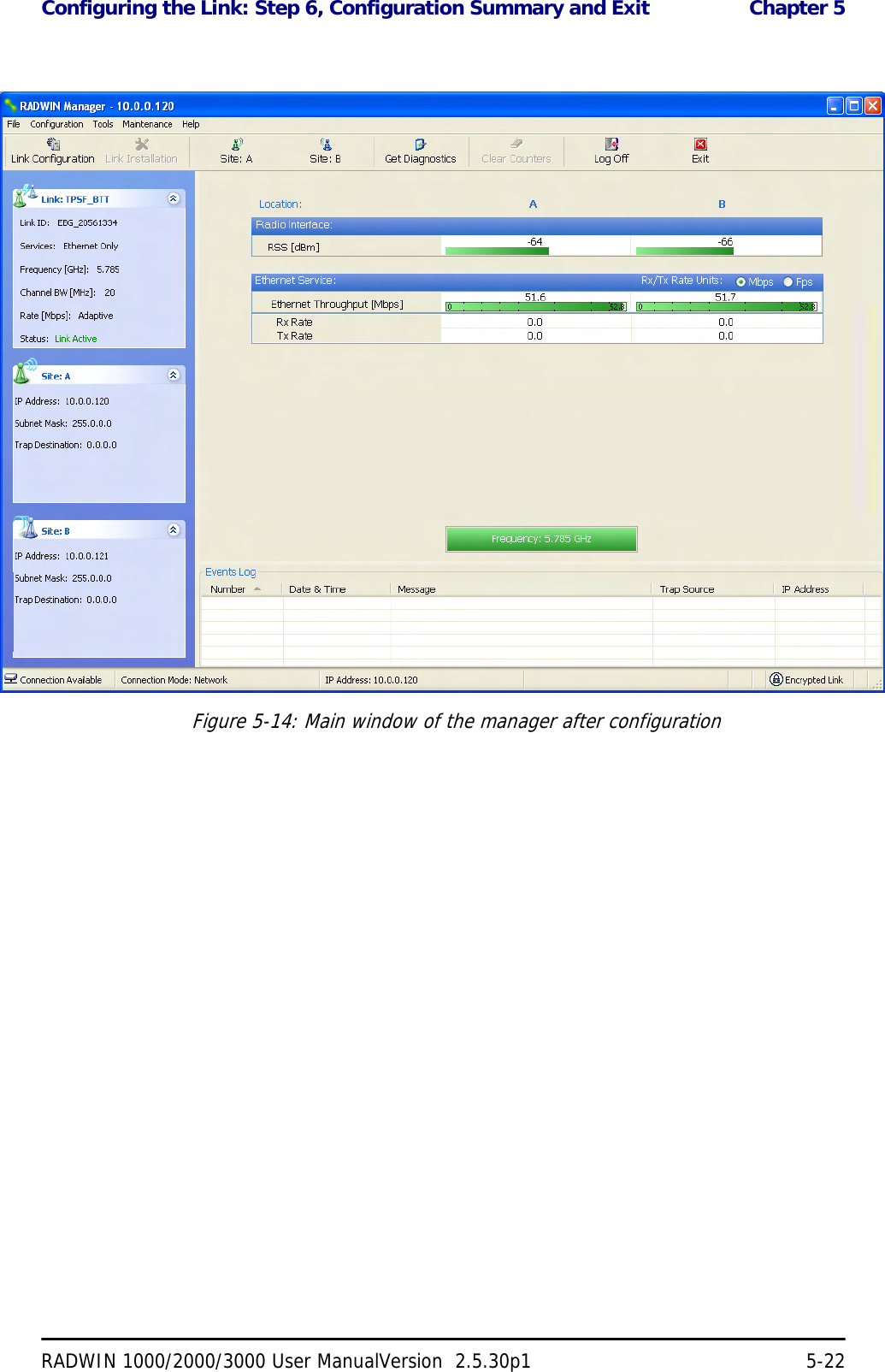
![Considerations for Changing Antenna Parameters Chapter 4RADWIN 1000/2000/3000 User ManualVersion 2.5.30p1 4-22The rates used by RADWIN 1000/2000/3000 are shown in Table 4-5 below:Considerations for Changing Antenna ParametersLet:maxAllowedTx Power denote the maximum Tx Power practically avail-able from an ODU. It appears as Tx Power per Radio in figure 4-16 below.maxRegEIRP denote the maximum EIRP available by regulation. It will be determined by three factors:• per band/regulation• per channel bandwidth•antenna gainIt appears in figure 4-16 as Max EIRP.maxRegTxPower denote the maximum regulatory Tx Power for the equipment, also having regard the above three pointsTable 4-8: RADWIN 1000/2000/3000 Transmission ratesRadio Modulation FEC Air-Rate [Mbps]Single BPSK 1/2 6.5Single QPSK 1/2 13Single QPSK 3/4 19.5Single 16QAM 1/2 26Single 16QAM 3/4 39Single 64QAM 2/3 52Single 64QAM 3/4 58.5Single 64QAM 5/6 65Dual BPSK 1/2 13Dual QPSK 1/2 26Dual QPSK 3/4 39Dual 16QAM 1/2 52Dual 16QAM 3/4 78Dual 64QAM 2/3 104Dual 64QAM 3/4 117Dual 64QAM 5/6 130](https://usermanual.wiki/Radwin/RW2030.Manual-part-1/User-Guide-1378193-Page-70.png)