Radwin RW2030 Outdoor radio unit operating in 3.65 GHz band User Manual STW
Radwin Ltd. Outdoor radio unit operating in 3.65 GHz band STW
Radwin >
Contents
Manual part 1
UM 3000-2530/11.10
RADWIN 1000/2000/3000
Broadband Wireless
Transmission System
User Manual
Version 2.5.30p1

RADWIN 1000/2000/3000 User ManualVersion 2.5.30p1 i
RADWIN 1000/2000/3000
User Manual
Notice
This manual contains information that is proprietary to RADWIN Ltd. (RADWIN hereafter). No
part of this publication may be reproduced in any form whatsoever without prior written
approval by RADWIN.
Right, title and interest, all information, copyrights, patents, know-how, trade secrets and
other intellectual property or other proprietary rights relating to this manual and to the
RADWIN products and any software components contained therein are proprietary products
of RADWIN protected under international copyright law and shall be and remain solely with
RADWIN.
The RADWIN name is a registered trademark of RADWIN Ltd. No right, license, or interest to
such trademark is granted hereunder, and you agree that no such right, license, or interest
shall be asserted by you with respect to such trademark.
You shall not copy, reverse compile or reverse assemble all or any portion of the User Manual
or any other RADWIN documentation or products. You are prohibited from, and shall not,
directly or indirectly, develop, market, distribute, license, or sell any product that supports
substantially similar functionality based or derived in any way from RADWIN products.Your
undertaking in this paragraph shall survive the termination of this Agreement.
This Agreement is effective upon your opening of a RADWIN product package and shall
continue until terminated. RADWIN may terminate this Agreement upon the breach by you of
any term thereof. Upon such termination by RADWIN, you agree to return to RADWIN any
RADWIN products and documentation and all copies and portions thereof.
For further information contact RADWIN at the address below or contact your local
distributor.
Disclaimer
The parameters quoted in this document must be specifically confirmed in writing before they
become applicable to any particular order or contract. RADWIN reserves the right to make
alterations or amendments to the detail specification at its discretion. The publication of
information in this document does not imply freedom from patent or other rights of RADWIN,
or others.

RADWIN 1000/2000/3000 User ManualVersion 2.5.30p1 ii
RADWIN Worldwide Offices
For technical support contact: support@radwin.com
For technical support in India only, contact: support-india@radwnin.com
For sales support contact: sales@radwin.com
Website: www.radwin.com
Corporate Headquarters
27 Habarzel Street
Tel Aviv, 69710
Israel
Tel: +972 3 766 2917
Support Headquarter
27 Habarzel Street
Tel Aviv, 69710
Israel
Tel: +972 3 766 2900
Mobile: +972 54 766 0044
RADWIN North America
900 Corporate Drive
Mahwah, NJ 07430
USA
Tel (1): 1 800 444 7234 / 341
Tel (2): +1 201 529 1100 / 341
Latin America Headquarters
Rua Grao Mogol 828
Belo Horizonte, MG 30310-010
Brazil
Tel (1): +55 31 919 76 402
Tel (2): +972 54 758 6808
India Headquarters
Mohan Co-operative Industrial Estate
E-13, B-1 Extn
New Delhi, 110044
India
Tel: +91 11 4053 9180
APAC Headquarters
1 Jalan Kuala #13-01
The Morningside, 239639
Singapore
Tel: +65 9878 3004
Indonesia Sales Office
Jl. Jenderal Sudirman Kav. 86
Jakarta, 10220
Indonesia
Tel: +62 8138 570 0657
Philippines Sales Office
37A. A luna St. West Rembo
Makati City, 1200
Philippines
Tel: +63 2882 6886
Mobile: +63 91 789 23427
China Sales Office
Asian Games Village
Huiyuan Gongyu J1312
Beijing 100101
China
Tel: +86 010 8498 0629

RADWIN 1000/2000/3000 User ManualVersion 2.5.30p1 iii
Regulatory Compliance
General Note
This system has achieved Type Approval in various countries around the world. This means
that the system has been tested against various local technical regulations and found to
comply. The frequency bands in which the system operates may be “unlicensed” and in these
bands, the system can be used provided it does not cause interference.
FCC/IC - Compliance
This equipment has been tested and found to comply with the limits for a Class B digital
device, pursuant to Part 15 of the FCC Rules and ICES-003 of IC. These limits are designed to
provide reasonable protection against harmful interference in a residential installation. This
equipment generates, uses and can radiate radio frequency energy and, if not installed and
used in accordance with the instructions, may cause harmful interference to radio
communications. However, there is no guarantee that interference will not occur in a
particular installation. If this equipment does cause harmful interference to radio or television
reception, which can be determined by turning the equipment off and on, the user is
encouraged to try to correct the interference by one or more of the following measures:
• Reorient or relocate the receiving antenna.
• Increase the separation between the equipment and receiver.
• Connect the equipment into an outlet on a circuit different from that to which the
receiver is connected.
Consult the dealer or an experienced radio/TV technician for help.
Changes or modifications to this equipment not expressly approved by the party responsible
for compliance (RADWIN Ltd.) could void the user's authority to operate the equipment.
Warning
It is the responsibility of the installer to ensure that when using the outdoor
antenna kits in the United States (or where FCC rules apply), only those
antennas certified with the product are used. The use of any antenna other
than those certified with the product is expressly forbidden in accordance to
FCC rules CFR47 part 15.204.
Caution
In accordance to IC standard RSS-Gen - To reduce potential radio
interference to other users, the antenna type and its gain should be so
chosen that the equivalent isotropically radiated power (e.i.r.p) is not more
than that permitted for successful communication
Caution
Outdoor units and antennas should be installed ONLY by experienced
installation professionals who are familiar with local building and safety
codes and, wherever applicable, are licensed by the appropriate government
regulatory authorities. Failure to do so may void the product warranty and
may expose the end user or the service provider to legal and financial
liabilities. Resellers or distributors of this equipment are not liable for injury,
damage or violation of regulations associated with the installation of outdoor
units or antennas. The installer should configure the output power level of
antennas according to country regulations and antenna type.

RADWIN 1000/2000/3000 User ManualVersion 2.5.30p1 iv
Indoor Units comply with part 15 of the FCC rules and ICES-003 standard. Operation is
subject to the following two conditions:
(1) These devices may not cause harmful interference.
(2) These devices must accept any interference received, including interference that may
cause undesired operation.
Canadian Emission Requirements for Indoor Units
This Class B digital apparatus complies with Canadian ICES-003.
Cet appareil numẻrique de la classe B est conforme ả la norme NMB-003 du Canada.
Safety Practices
Applicable requirements of National Electrical Code (NEC), NFPA 70; and the National
Electrical Safety Code, ANSI/IEEE C2, must be considered during installation.
NOTES:
1. A Primary Protector is not required to protect the exposed wiring as long as the exposed
wiring length is limited to less than or equal to 140 feet, and instructions are provided to
avoid exposure of wiring to accidental contact with lightning and power conductors in
accordance with NEC Sections 725-54 (c) and 800-30.
In all other cases, an appropriate Listed Primary Protector must be provided. Refer to Articles
800 and 810 of the NEC for details.
2. For protection of ODU against direct lightning strikes, appropriate requirements of NFPA
780 should be considered in addition to NEC.
3. For Canada, appropriate requirements of Section 60 of the CEC 22.1should be considered
as applicable.
4. E1/T1 ports are intended for connection to indoor lines only and are not exposed to
outdoor plants.
Warning
The antenna used for this transmitter must be installed to provide a
separation distance of at least 225cm from all persons and must not be co-
located or operated in conjunction with any other antenna or transmitter.
Warning
This product was tested with special accessories - indoor unit (IDU or
PoE), FTP Cat 5e shielded cable with sealing gasket, 12 AWG grounding
cable - which must be used with the unit to insure compliance.

RADWIN 1000/2000/3000 User ManualVersion 2.5.30p1 v
Table of Contents
Notice....................................................................................................................... i
RADWIN Worldwide Offices.................................................................................... ii
Regulatory Compliance..............................................................................................iii
Chapter 1 Introduction
Welcome! .............................................................................................................. 1-1
Key Applications..................................................................................................... 1-2
WiMAX and IP Backhaul ......................................................................................1-2
Broadband Access ..............................................................................................1-2
Private Networks ................................................................................................1-3
Key Features of RADWIN 1000/2000/3000............................................................... 1-3
RADWIN 1000/2000/3000 Link................................................................................ 1-5
The Radio Outdoor Unit (ODU) ............................................................................1-5
The Indoor Units (IDU).......................................................................................1-7
IDU-C.........................................................................................................................1-7
IDU-E.........................................................................................................................1-8
Power Over Ethernet (PoE) Devices .....................................................................1-8
Antennas ...........................................................................................................1-9
Flat Panel Antennas................................................................................................... 1-10
Parabolic Dish Antennas ............................................................................................ 1-11
RADWIN Manager.............................................................................................1-11
Accessories ......................................................................................................1-12
Documentation set supplied with RADWIN 1000/2000/3000 ................................1-12
How to Use this Manual ........................................................................................ 1-13
A Little Terminology ............................................................................................. 1-13
Conventions Used in this Manual ........................................................................... 1-15
Notifications.....................................................................................................1-15
Typographical conventions ................................................................................1-15
General .................................................................................................................... 1-15
Software................................................................................................................... 1-15
Windows Terminology.......................................................................................1-16
Chapter 2 Site Preparation
Planning the Link Site............................................................................................. 2-1
Overview ...........................................................................................................2-1
The Site Survey...................................................................................................... 2-1
Introduction.......................................................................................................2-1
Recommended Equipment...................................................................................2-1
Stage 1: Preliminary Survey .................................................................................... 2-2
Stage 2: Physical Survey......................................................................................... 2-3
Additional Outdoor Site Requirements..................................................................2-4
Additional Indoor Site Requirements ....................................................................2-4
Stage 3: RF Survey................................................................................................. 2-4
Chapter 3 Hardware Installation
Safety Practices...................................................................................................... 3-1
Preventing overexposure to RF energy.................................................................3-1
Grounding..........................................................................................................3-1
Protection against Lightning ................................................................................3-2
General..............................................................................................................3-2
Package Contents................................................................................................... 3-2
ODU Package Contents .......................................................................................3-2
IDU Package Contents ........................................................................................3-4
External Antenna Package Contents.....................................................................3-5
Additional Tools and Materials Required................................................................... 3-5
Tools and Materials.............................................................................................3-5
Cables and connectors........................................................................................3-5
Hardware Installation Sequence .............................................................................. 3-5
Outdoor installation................................................................................................ 3-6
Mounting the ODU..............................................................................................3-6

RADWIN 1000/2000/3000 User ManualVersion 2.5.30p1 vi
Mounting external antennas ................................................................................3-7
Mounting the Lightning Protection Devices ...........................................................3-7
Outdoor Connections ..........................................................................................3-8
Indoor Installation.................................................................................................. 3-8
IDU-E Installation........................................................................................................3-8
Mounting the IDU-C............................................................................................3-8
Connecting power to the IDU ............................................................................3-11
Connecting the ODU to the IDU.........................................................................3-12
Installing a Link using PoE Devices.....................................................................3-12
Connecting User Equipment...............................................................................3-12
Connecting and Aligning ODUs / Antennas ............................................................. 3-13
Chapter 4 Link Installation: The RADWIN Manager
Installing theRADWIN Manager Application .............................................................. 4-1
Minimum System Requirements...........................................................................4-1
Installing the Software........................................................................................4-1
Starting the RADWIN Manager ................................................................................ 4-2
Login Errors........................................................................................................... 4-5
Unsupported Device............................................................................................4-5
Incorrect IP Address ...........................................................................................4-6
Incorrect Password.............................................................................................4-6
Continuing without an IP Address............................................................................ 4-6
Changing the Log On Password ...........................................................................4-7
Installing the Link: First steps.................................................................................. 4-7
Default Settings..................................................................................................4-9
Front Panel LEDs on the IDU-C............................................................................4-9
Installation Menu and Toolbar Functionality........................................................4-10
Installing the Link: Overview................................................................................. 4-13
Installing the Link: Step 1, Start the Wizard ........................................................... 4-14
Installing the Link: Step 2, System Parameters....................................................... 4-14
Changing the Link Password..............................................................................4-16
Installing the Link: Step 3, Channel Settings........................................................... 4-17
Installing the Link: Step 4, Tx Power and Antenna Settings ..................................... 4-19
General............................................................................................................4-20
Dual Antennas at Both Sites ..............................................................................4-20
Single Antennas at Both Sites............................................................................4-21
Single and Dual Antennas..................................................................................4-21
Considerations for Changing Antenna Parameters ...............................................4-22
Installing the Link: Step 5, Services ....................................................................... 4-25
Installing the Link: Step 6, Installation Summary and Exit ....................................... 4-26
Chapter 5 Configuring the Link
Link Configuration: Getting Started.......................................................................... 5-1
The Main Window of the RADWIN Manager..........................................................5-1
The RADWIN Manager Toolbar............................................................................5-2
The RADWIN Manager Main Menu .......................................................................5-3
Elements of the RADWIN Manager Main Window ..................................................5-6
Configuring the Link: Overview.............................................................................. 5-10
Configuring the Link: Step 1, Start the Wizard........................................................ 5-11
Configuring the Link: Step 2, System Parameters.................................................... 5-11
Configuring the Link: Step 3, Channel Settings ....................................................... 5-12
Configuring the Link: Step 4, Tx Power and Antenna Settings.................................. 5-18
Configuring the Link: Step 5, Services.................................................................... 5-20
Configuring the Link: Step 6, Configuration Summary and Exit................................. 5-21
Chapter 6 Site Configuration
Configuring the Site................................................................................................ 6-1
Editing the Configuration Parameters by Site ........................................................6-1
Functions on the left of the dialog box:.........................................................................6-2
Functions at the top of the dialog box:..........................................................................6-2
Viewing Air Interface Details ................................................................................... 6-3
Changing the Transmit Power ................................................................................. 6-4

RADWIN 1000/2000/3000 User ManualVersion 2.5.30p1 vii
Site Management: IP Address and VLAN .................................................................. 6-4
Configuring the ODU Address ..............................................................................6-4
Configuring VLAN Settings...................................................................................6-5
Lost or forgotten VLAN ID............................................................................................6-7
Setting the Date and Time ...................................................................................... 6-7
Ethernet Properties................................................................................................. 6-9
Configuring the Bridge ........................................................................................6-9
ODU Mode................................................................................................................ 6-10
IDU Aging time ......................................................................................................... 6-10
Configuring Ethernet Ports Mode .......................................................................6-11
Setting the Maximum Information Rate..............................................................6-12
Displaying the Inventory....................................................................................... 6-12
Security Features ................................................................................................. 6-13
Changing the Link Password..............................................................................6-14
RADWIN Manager Community Strings................................................................6-14
Editing Community Strings......................................................................................... 6-15
Forgotten Community string....................................................................................... 6-16
Muting the alignment tone.................................................................................... 6-17
Setting External Alarm Inputs................................................................................ 6-17
Managing Configuration Files................................................................................. 6-18
Backup Configuration to a File ...........................................................................6-18
Restoring a Configuration File............................................................................6-19
Resetting .........................................................................................................6-19
Configuration with Telnet...................................................................................... 6-20
Chapter 7 Monitoring and Diagnostics
Retrieving Link Information (Get Diagnostics)........................................................... 7-1
Link Compatibility................................................................................................... 7-3
Reinstalling and Realigning a Link............................................................................ 7-3
The Link Budget Calculator ..................................................................................... 7-4
Performance Monitoring.......................................................................................... 7-4
The Monitor Log.................................................................................................7-4
Saving the Monitor Log................................................................................................7-4
Viewing Performance Reports.......................................................................................7-5
Performance Monitoring Report Toolbar........................................................................7-9
Setting Air Interface Thresholds ...................................................................................7-9
The Events Log ................................................................................................7-10
RADWIN Manager Traps ...................................................................................7-11
Setting the Events Preferences................................................................................... 7-12
Saving the Events Log ............................................................................................... 7-13
Reverting Alarm Messages......................................................................................... 7-14
Active Alarms............................................................................................................ 7-14
Remote Power Fail Indication..................................................................................... 7-15
Troubleshooting ................................................................................................... 7-16
Replacing an ODU ................................................................................................ 7-16
Restoring Factory Setup........................................................................................ 7-17
Online Help.......................................................................................................... 7-17
Customer Support ................................................................................................ 7-17
Appendix A Technical Specifications
Configuration........................................................................................................ A-1
Radio ................................................................................................................... A-1
Ethernet Interface................................................................................................. A-4
Management......................................................................................................... A-4
Mechanical............................................................................................................ A-4
Power................................................................................................................... A-5
Environmental....................................................................................................... A-5
Safety................................................................................................................... A-5
EMC ..................................................................................................................... A-5
Air Interface.......................................................................................................... A-5
Appendix B Wiring Specifications
ODU-IDU Cable..................................................................................................... B-1

RADWIN 1000/2000/3000 User ManualVersion 2.5.30p1 viii
User Port Connectors............................................................................................ B-1
LAN Port........................................................................................................... B-1
IDU-C Alarm Connector...................................................................................... B-3
Appendix C Pole and Wall Installation
ODU Mounting Kit Contents.................................................................................... C-1
Mounting RADWIN 1000/2000/3000 on a pole......................................................... C-2
Mounting RADWIN 1000/2000/3000 on a Wall ........................................................ C-3
Mounting an External Antenna ............................................................................... C-3
Appendix D Link Budget Calculator
Overview.............................................................................................................. D-1
User Input ........................................................................................................ D-1
Link Budget Calculator Internal Data................................................................... D-1
Calculations .......................................................................................................... D-2
EIRP.................................................................................................................D-2
Expected RSS and Fade Margin........................................................................... D-2
Min and Max Range ........................................................................................... D-2
Service.............................................................................................................. D-2
Availability ........................................................................................................ D-2
Antenna Height ................................................................................................. D-3
Running the Link Budget Calculator ........................................................................ D-3
About the Fresnel Zone........................................................................................ D-13
Appendix E Lightning Protection and Grounding Guidelines
Grounding for Antenna Cable .................................................................................. E-1
Grounding for Indoor/Outdoor Units ........................................................................ E-2
ODU Grounding..................................................................................................E-2
IDU Grounding ...................................................................................................E-2
External Lightning Surge Suppressors and Grounding................................................ E-3
Internal ESD Protection circuits ............................................................................... E-7
Appendix F MIB Reference
Introduction........................................................................................................... F-1
About the MIB....................................................................................................F-1
Terminology.......................................................................................................F-1
Interface API ......................................................................................................... F-1
Control Method...................................................................................................F-1
Community String...............................................................................................F-2
Private MIB Structure ............................................................................................. F-2
MIB Parameters ..................................................................................................... F-4
Supported Variables from the RFC 1213 MIB ........................................................F-4
MIB Parameters..................................................................................................F-5
MIB Traps............................................................................................................ F-18
General............................................................................................................F-18
Trap parameters...............................................................................................F-18
RADWIN Manager Traps ...................................................................................F-21
Appendix G External Alarms Specification
External Alarms Specification.................................................................................. G-1
Appendix H Combo Configuration Tool
What is the Combo Configuration Tool? .................................................................. H-1
Who may use the Combo Configuration Tool........................................................... H-1
Caveat to the use of the Combo Configuration Tool ................................................. H-1
Prerequisites to using the Combo Configuration Tool................................................ H-2
Operating the Combo Configuration Tool................................................................. H-2
Before using the Combo Configuration Tool............................................................. H-2
Using the Combo Configuration Tool....................................................................... H-2
If you receive an error message ............................................................................. H-6
Appendix I Regional Notice: French Canadian
Procédures de sécurité............................................................................................ I-1
Généralités......................................................................................................... I-1
Mise à la terre .................................................................................................... I-1

RADWIN 1000/2000/3000 User ManualVersion 2.5.30p1 ix
Protection contre la foudre.................................................................................. I-2
Précautions de sécurité pendant le montage de ODU ............................................ I-2
Connecter la terre à IDU-C.................................................................................. I-3
Installation sur pylône et mur.................................................................................. I-4
Contenu du kit de montage ODU ......................................................................... I-4
Montage sur un pylône ....................................................................................... I-5
Montage sur un mur ........................................................................................... I-6
Montage d'une antenne externe........................................................................... I-7
Contenu du kit de montage d'une antenne externe ............................................... I-7
Index

RADWIN 1000/2000/3000 User ManualVersion 2.5.30p1 x
List of Figures
FIGURE 1-1 TYPICAL WIMAX AND IP BACKHAUL APPLICATION ....................................................1-2
FIGURE 1-2 TYPICAL BROADBAND ACCESS APPLICATION ...........................................................1-2
FIGURE 1-3 PRIVATE NETWORK..........................................................................................1-3
FIGURE 1-4 EXAMPLE OF LINK ARCHITECTURE - SYSTEM COMPONENTS ........................................1-5
FIGURE 1-5 ODU FORM FACTORS.......................................................................................1-6
FIGURE 1-6 IDU-C FRONT PANEL.......................................................................................1-8
FIGURE 1-7 IDU-E - FRONT VIEW.......................................................................................1-8
FIGURE 1-8 IDU-E: REAR PANEL........................................................................................1-8
FIGURE 1-9 POE DEVICE - SHOWING THE RADIO ETHERNET PORT...............................................1-9
FIGURE 1-10 ODU WITH INTEGRATED FLAT PANEL ANTENNA.....................................................1-9
FIGURE 1-11 FLAT PANEL ANTENNA ..................................................................................1-10
FIGURE 1-12 EXTERNAL ANTENNAS - PARABOLIC DISH...........................................................1-11
FIGURE 1-13 RADWIN MANAGER SCREEN..........................................................................1-12
FIGURE 1-14 SITE CONFIGURATION WINDOW WITH OPEN MANAGEMENT PANEL............................1-17
FIGURE 3-1 ODU MOUNTING KIT .......................................................................................3-3
FIGURE 3-2 CONNECTORIZED ODU - FRONT AND REAR VIEWS...................................................3-3
FIGURE 3-3 INTEGRATED ODU - FRONT AND REAR VIEWS ........................................................3-4
FIGURE 3-4 IDU-C PACKAGE CONTENTS - THE IDU-C.............................................................3-4
FIGURE 3-5 IDU-C PACKAGE CONTENTS - THE MOUNTING KIT AND DC POWER PLUGS .....................3-4
FIGURE 3-6 TYPICAL INSTALLATION DIAGRAM (WITH EXTERNAL ANTENNA)....................................3-6
FIGURE 3-7 NEW STYLE IDU-E: REAR PANEL ........................................................................3-8
FIGURE 3-8 IDU-C FRONT PANEL .......................................................................................3-9
FIGURE 3-9 IDU-C - A PERSPECTIVE VIEW ...........................................................................3-9
FIGURE 3-10 IDU-C LEDS.............................................................................................3-10
FIGURE 3-11 DU-C OWER CONNECTORS.............................................................................3-12
FIGURE 3-12 BEEP SEQUENCE FOR ANTENNA ALIGNMENT........................................................3-14
FIGURE 4-1 LAN PORTS ON THE FRONT PANEL OF THE IDU-C...................................................4-2
FIGURE 4-2 PINGING AN UNINSTALLED AND UNCONFIGURED LINK................................................4-3
FIGURE 4-3 LOGIN SCREEN ...............................................................................................4-3
FIGURE 4-4 LOGIN SCREEN WITH COMMUNITY OPTIONS VISIBLE.................................................4-5
FIGURE 4-5 UNSUPPORTED DEVICE MESSAGE .........................................................................4-5
FIGURE 4-6 UNREACHABLE DEVICE MESSAGE..........................................................................4-6
FIGURE 4-7 OPENING RADWIN MANAGER WINDOW PRIOR TO INSTALLATION ...............................4-8
FIGURE 4-8 IDU-C FRONT PANEL LEDS............................................................................4-10
FIGURE 4-9 LINK INSTALLATION WIZARD............................................................................4-14
FIGURE 4-10 : INSTALLATION WIZARD, SYSTEM DIALOG BOX ..................................................4-15
FIGURE 4-11 CHANGE LINK PASSWORD DIALOG BOX..............................................................4-16
FIGURE 4-12 LOST OR FORGOTTEN LINK PASSWORD RECOVERY................................................4-17
FIGURE 4-13 CHANNEL SETTINGS - AUTOMATIC CHANNEL SELECTION........................................4-18
FIGURE 4-14 CHANNEL SETTINGS - SHOWING AVAILABLE INSTALLATION RATES ............................4-19
FIGURE 4-15 TRANSMISSION POWER AND ANTENNA PARAMETERS.............................................4-20
FIGURE 4-16 ANTENNA CONFIGURATION DIALOG WITH OPENED TYPE SELECTION .........................4-23
FIGURE 4-17 ANTENNA PARAMETERS CHANGE WARNING..........................................................4-24
FIGURE 4-18 TX POWER LIMITS.......................................................................................4-24
FIGURE 4-19 SERVICES AND RATES DIALOG.........................................................................4-25
FIGURE 4-20 INSTALLATION WIZARD EXIT SUMMARY ............................................................4-26
FIGURE 4-21 MAIN WINDOW OF THE MANAGER AFTER INSTALLATION.........................................4-27
FIGURE 5-1 MAIN WINDOW, WIRELESS LINK IS ACTIVE ..........................................................5-2
FIGURE 5-2 ETHERNET BANDWIDTH INDICATION ....................................................................5-8
FIGURE 5-3 LINK CONFIGURATION WIZARD.........................................................................5-11
FIGURE 5-4 CONFIGURATION WIZARD, SYSTEM DIALOG BOX....................................................5-12
FIGURE 5-5 CHANNEL SETTINGS DIALOG BOX - AUTOMATIC CHANNEL SELECTION.........................5-13
FIGURE 5-6 SEARCHING FOR THE BEST OPERATING CHANNEL ...................................................5-14
FIGURE 5-7 CHANNEL SETTINGS WITHOUT AUTOMATIC CHANNEL SELECTION................................5-15
FIGURE 5-8 CHANNEL FREQUENCY OPTIONS.........................................................................5-16
FIGURE 5-9 CHOOSING AN “OTHER” OPERATING CHANNEL FREQUENCY ......................................5-17
FIGURE 5-10 TRANSMISSION POWER AND ANTENNA PARAMETERS.............................................5-18

RADWIN 1000/2000/3000 User ManualVersion 2.5.30p1 xi
FIGURE 5-11 ANTENNA CONFIGURATION DIALOG WITH OPENED TYPE SELECTION .........................5-19
FIGURE 5-12 SERVICES AND RATES DIALOG.........................................................................5-20
FIGURE 5-13 CONFIGURATION WIZARD EXIT SUMMARY..........................................................5-21
FIGURE 5-14 MAIN WINDOW OF THE MANAGER AFTER CONFIGURATION ......................................5-22
FIGURE 6-1 CONFIGURATION DIALOG BOX ............................................................................6-2
FIGURE 6-2 AIR INTERFACE DETAILS....................................................................................6-3
FIGURE 6-3 CHANGING THE TRANSMIT POWER.......................................................................6-4
FIGURE 6-4 MANAGEMENT ADDRESSES - SITE CONFIGURATION DIALOG BOX..................................6-5
FIGURE 6-5 CONFIGURING MANAGEMENT TRAFFIC VLAN SETTINGS .............................................6-6
FIGURE 6-6 DATE AND TIME CONFIGURATION........................................................................6-8
FIGURE 6-7 CHANGE DATE AND TIME ..................................................................................6-8
FIGURE 6-8 DATE AND TIME CONFIGURED FROM AN NTP SERVER...............................................6-9
FIGURE 6-9 BRIDGE CONFIGURATION - SITE CONFIGURATION DIALOG BOX .................................6-10
FIGURE 6-10 INVENTORY SCREEN .....................................................................................6-13
FIGURE 6-11 AVAILABLE SECURITY FEATURES.......................................................................6-14
FIGURE 6-12 CHANGING THE COMMUNITY STRING................................................................6-16
FIGURE 6-13 ALTERNATIVE COMMUNITY DIALOG BOX ............................................................6-17
FIGURE 6-14 EXTERNAL ALARM CONFIGURATION ..................................................................6-18
FIGURE 6-15 TELNET MANAGEMENT SCREEN .......................................................................6-22
FIGURE 7-1 GET DIAGNOSTICS DIALOG BOX .........................................................................7-2
FIGURE 7-2 PREFERENCES DIALOG BOX.................................................................................7-5
FIGURE 7-3 BASIC PERFORMANCE MONITORING REPORT ..........................................................7-6
FIGURE 7-4 A TYPICAL PERFORMANCE MONITORING REPORT.....................................................7-6
FIGURE 7-5 THRESHOLD CONFIGURATION DIALOG BOX .............................................................7-9
FIGURE 7-6 EVENTS LOG DISPLAY.....................................................................................7-10
FIGURE 7-7 PREFERENCES DIALOG BOX...............................................................................7-13
FIGURE 7-8 ACTIVE ALARMS SUMMARY ..............................................................................7-15
FIGURE 7-9 ONLINE HELP FOR RADWIN 1000/2000/3000..................................................7-17
FIGURE B-1 EXAMPLE FOR CONNECTING THE ALARM CONNECTOR................................................ B-4
FIGURE C-4 MOUNTING ON A POLE..................................................................................... C-2
FIGURE C-5 MOUNTING ON A WALL ................................................................................... C-3
FIGURE D-1 ACCESSING THE LINK BUDGET CALCULATOR ......................................................... D-4
FIGURE D-2 LINK BUDGET SCREEN..................................................................................... D-5
FIGURE D-3 PRODUCT SELECTOR ....................................................................................... D-7
FIGURE D-4 RATE SELECTOR............................................................................................. D-8
FIGURE D-5 CALCULATION OF DISTANCE FROM SITE COORDINATES............................................ D-9
FIGURE D-6 CLIMACTIC C FACTORS.................................................................................. D-10
FIGURE D-7 CLIMACTIC C FACTOR DESCRIPTION ................................................................. D-11
FIGURE D-8 WORLD MAP SHOWING C FACTOR CONTOURS ..................................................... D-12
FIGURE D-9 FRESNEL ZONE ............................................................................................ D-13
FIGURE E-1 GROUNDING ANTENNA CABLES ............................................................................E-2
FIGURE E-2 GROUNDING A TYPICAL POLE INSTALLATION...........................................................E-3
FIGURE E-3 GROUNDING A TYPICAL WALL INSTALLATION...........................................................E-4
FIGURE E-4 ODU SURGE SUPPRESSOR AND GROUNDING ..........................................................E-4
FIGURE E-5 TRANSTECTOR’S SURGE SUPPRESSOR ...................................................................E-5
FIGURE E-6 SURGE SUPPRESSOR AND GROUNDING AT BUILDING ENTRY POINT................................E-7
FIGURE F-1 TOP LEVEL SECTIONS OF THE PRIVATE MIB...........................................................F-3
FIGURE I-4 MONTAGE SUR UN PYLÔNE ................................................................................. I-5
FIGURE I-5 MONTAGE SUR UN MUR ..................................................................................... I-6

RADWIN 1000/2000/3000 User ManualVersion 2.5.30p1 xii
List of Tables
TABLE 1-1 AVAILABLE ODU PRODUCTS - RELEASE 2.5.30P1 ....................................................1-7
TABLE 1-2 RELEASE 2.1 IDU-C PRODUCTS...........................................................................1-7
TABLE 3-1 COMPONENTS OF AN IDU-C FRONT PANEL............................................................3-10
TABLE 3-2 IDU-C FRONT PANEL LEDS..............................................................................3-11
TABLE 4-1 PC REQUIREMENTS FOR THE RADWIN MANAGER APPLICATION...................................4-1
TABLE 4-2 RADWIN MANAGER: OFFLINE FUNCTIONALITY........................................................4-7
TABLE 4-3 DEFAULT SETTINGS...........................................................................................4-9
TABLE 4-4 FRONT PANEL LEDS........................................................................................4-10
TABLE 4-5 RADWIN MANAGER MAIN MENU FUNCTIONALITY ...................................................4-11
TABLE 4-6 RADWIN MANAGER TOOLBAR..........................................................................4-12
TABLE 4-7 LINK INSTALLATION WIZARD .............................................................................4-13
TABLE 4-8 RADWIN 1000/2000/3000 TRANSMISSION RATES...............................................4-22
TABLE 5-1 RADWIN MANAGER TOOLBAR............................................................................5-3
TABLE 5-2 RADWIN MANAGER MAIN MENU FUNCTIONALITY .....................................................5-4
TABLE 5-3 LINK DETAILS..................................................................................................5-6
TABLE 5-4 LINK SITE DETAILS, SITE A AND SITE B.................................................................5-7
TABLE 5-5 STATUS BAR INDICATORS....................................................................................5-9
TABLE 5-6 LINK CONFIGURATION WIZARD ..........................................................................5-10
TABLE 6-1 ODU MODE CONFIGURATION FOR COMMON...........................................................6-11
TABLE 6-2 TELNET COMMANDS ........................................................................................6-20
TABLE 7-1 GET DIAGNOSTICS DATA AND DESCRIPTION............................................................7-2
TABLE 7-2 LINK COMPATIBILITY TRAP MESSAGES ...................................................................7-3
TABLE 7-3 EXPLANATION OF PERFORMANCE DATA....................................................................7-8
TABLE 7-4 ACTION OF THE TOOLBAR BUTTONS.......................................................................7-9
TABLE 7-5 RADWIN MANAGER TRAP MESSAGES..................................................................7-11
TABLE 7-6 ACTIVE ALARMS COMMAND BUTTONS ...................................................................7-15
TABLE 7-7 LED FAULT INDICATORS ...................................................................................7-16
TABLE 7-8 TROUBLESHOOTING.........................................................................................7-16
TABLE B-1 ODU-IDU CONNECTOR PINOUT.......................................................................... B-1
TABLE B-2 FAST ETHERNET CONNECTOR PINOUT................................................................... B-2
TABLE B-3 IDU-C ALARM CONNECTOR (DRY-CONTACT) ......................................................... B-3
TABLE B-4 TERMINAL BLOCK 3-PIN -48VDC........................................................................ B-4
TABLE C-1 BILL OF MATERIALS: ODU MOUNTING KIT............................................................. C-1
TABLE F-1 SUPPORTED RFC 1213 VARIABLES .......................................................................F-4
TABLE F-2 PRIVATE MIB PARAMETERS.................................................................................F-5
TABLE F-3 MIB TRAPS...................................................................................................F-18
TABLE G-1 OUTPUT ALARMS PINOUT .................................................................................. G-1

RADWIN 1000/2000/3000 User ManualVersion 2.5.30p1 1-1
Chapter 1
Introduction
Welcome!
Welcome to the RADWIN 1000/2000/3000 radio series, designed for the IP
and WiMAX Backhaul, Private Networks and Broadband Access global mar-
kets. The RADWIN 1000/2000/3000 series is an innovation in high-capacity
carrier-grade sub-6GHz radios, and designed to meet the requirements of
current and next-generation markets and applications. RADWIN 1000/2000/
3000 also features software configurable antenna port activation enabling
single (RADWIN 1000) or dual (RADWIN 2000) antenna port operation. The
RADWIN 3000 series is identifier for software configured Point to Multipoint
devices. The device configured as RADWIN 2000 has an advanced air-inter-
face based on MIMO, antenna diversity.
The RADWIN 1000/2000/3000 radio series offers unmatched performance
and carrier-class quality with the following features:
• Superior spectral efficiency at 5, 10, 20MHz and 40MHz channels in
the 5.3, 5.4 and 5.8 GHz spectrum bands.
• High Ethernet capacity (up to 270Mbps at 40MHz channel band-
width.)
• Combo frequency products for maximum flexibility
• Advanced air-interface based on MIMO, built-in diversity and OFDM
technologies
• Superior range performance
• Simple installation and management
•High Tx power
The RADWIN 1000/2000/3000 radio series supports the 2.4, 4.9, 5.3, 5.4
and 5.8 GHz spectrum bands, and complies with international standards
and regulations (FCC, IC Canada). The 5.8 GHz spectrum band complies
with FCC rule 47 CFR Part 15 subparts C and E.
The model RADWIN 1000 RW-1020-0150 / RADWIN 2000 RW-2020-0150
supports the 2.4GHz band and complies with FCC and IC standards.
Key Applications Chapter 1
RADWIN 1000/2000/3000 User ManualVersion 2.5.30p1 1-2
The RADWIN 1000 3GHz Band / RADWIN 2000 3GHz Band / RADWIN 3000
3GHz Band support the 3.5 and 3.65 GHz spectrum bands and comply with
FCC and IC standards.
Key Applications
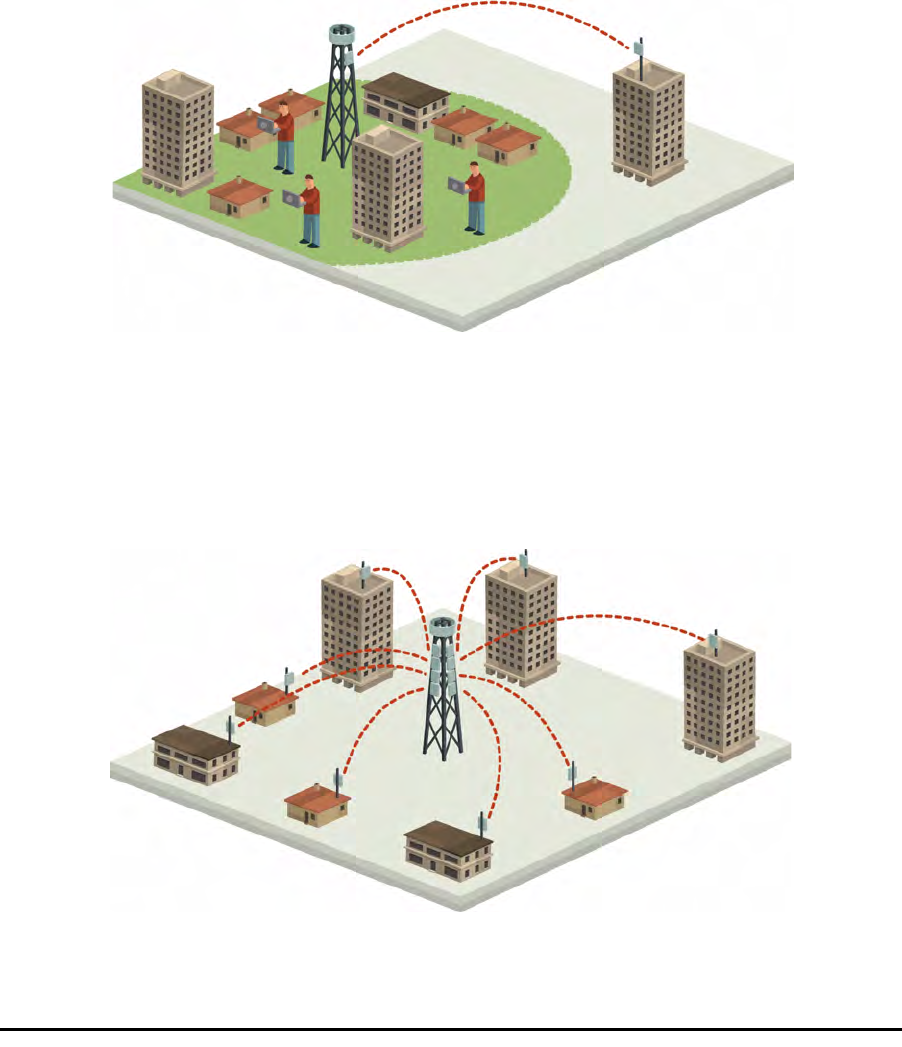
WiMAX and IP Backhaul
The RADWIN 1000/2000/3000 radio series offers WiMAX operators and ISPs
a unique, highly scalable and cost-effective backhaul solution. Designed to
suit a wide range of topologies, RADWIN 1000/2000/3000 is easy to install
and maintain, enabling operators to quickly and efficiently expand their net-
works and introduce new services to a growing subscriber base.
Figure 1-1: Typical Wimax and IP Backhaul application
Broadband Access
With RADWIN 1000/2000/3000, service providers can quickly and efficiently
expand their networks, and provide high-capacity services that meet the
increasing demand for high-quality, high-speed broadband.
Figure 1-2: Typical Broadband Access application
Private Networks Chapter 1
RADWIN 1000/2000/3000 User ManualVersion 2.5.30p1 1-3
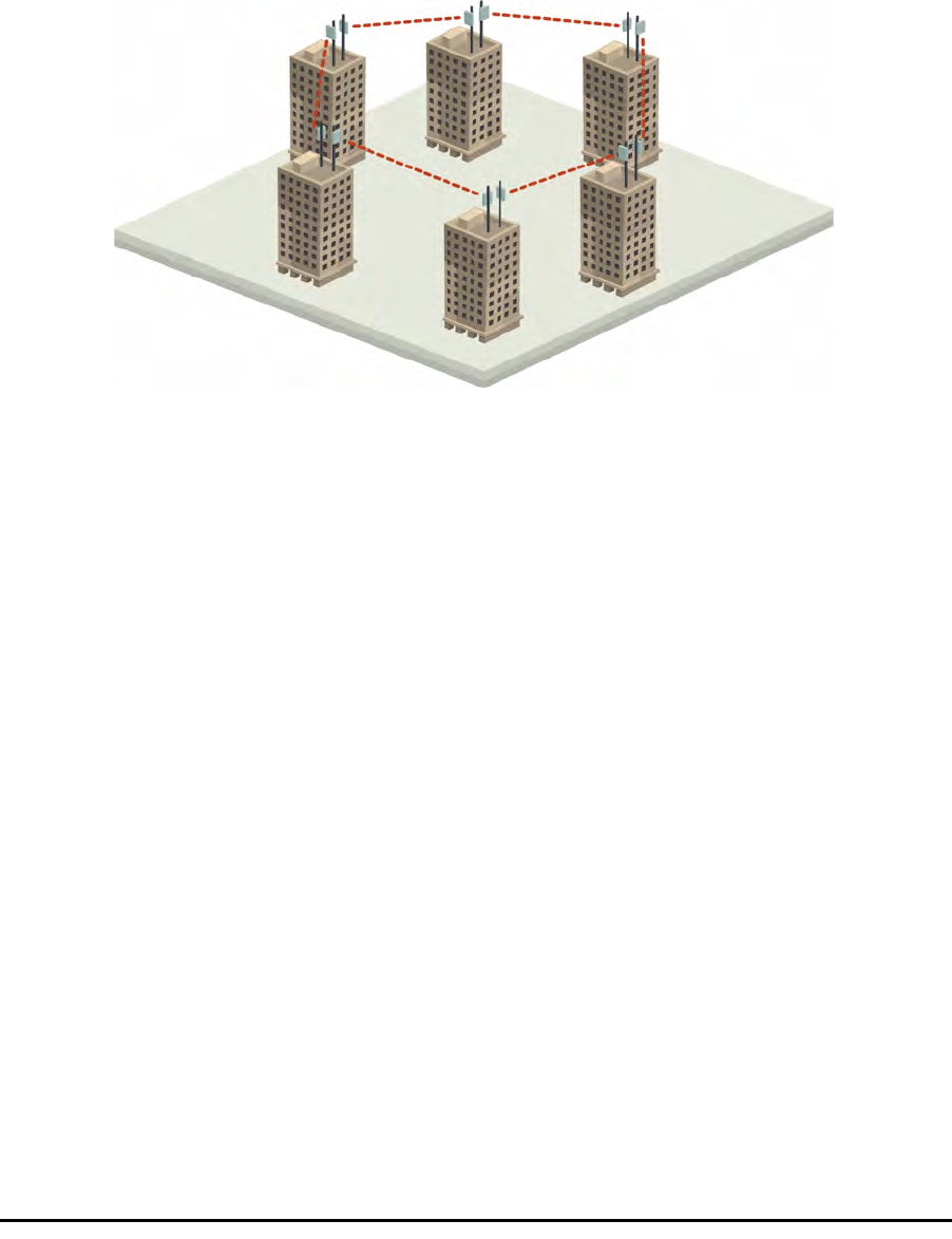
Private Networks
RADWIN 1000/2000/3000 is the ultimate solution for private networks such
as enterprises, education, government and utility organizations that wish to
own and manage their own networks and eliminate the costly recurring
charges from service providers.
RADWIN 1000/2000/3000's cost-effective solution enables a variety of orga-
nizations to connect geographically dispersed sites at ranges of up to 80km
(50 miles).
Figure 1-3: Private Network
Key Features of RADWIN 1000/2000/3000
Some of the outstanding features of the RADWIN 1000/2000/3000 radio
series are as follows:
⇒High Capacity
The RADWIN 1000/2000 system provides a high-capacity link of up
to 270Mbps at 40MHz channel bandwidth.
⇒Superior Spectral Efficiency
Built on advanced MIMO and OFDM technologies, the RADWIN
1000/2000 system provides a high-capacity link at channel band-
width of 40MHz. This channel bandwidth supports high robustness
of the air interface under interference and harsh conditions. In coun-
tries where applicable, narrow channel bandwidth reduces the cost
of the spectrum license.
⇒Advanced Air Interface
The RADWIN 1000/2000/3000 system provides an advanced air-
interface based on MIMO, built-in diversity and OFDM technologies,
resulting in an exceptionally robust air interface.
Using the following technologies, the RADWIN 1000/2000/3000 air
interface is designed to ensure nonstop, high quality transmission,
even under interference and harsh conditions:

Key Features of RADWIN 1000/2000/3000 Chapter 1
RADWIN 1000/2000/3000 User ManualVersion 2.5.30p1 1-4
• Automatic Adaptive Rate (AAR) is a mechanism that dynami-
cally adapts the air interface rate by changing both the signal
modulation and coding.
• Automatic Channel Selection (ACS) chooses the best channel by
monitoring the available radio channels and dynamically select-
ing a channel which is best suited for transmission at any given
time.
• Automatic Repeat Request (ARQ) is a mechanism for error con-
trol during data transmission. When the receiver detects an
error in the received information, it automatically requests the
transmitter to resend the information. This process is repeated
until the transmission is error free or the error continues
beyond a predetermined number of maximum transmissions.
RADWIN 1000/2000/3000's ARQ mechanism is optimized for
time-critical traffic.
• Forward Error Correction (FEC) with very low overhead and
algorithms specifically designed for the varying conditions of
license-exempt frequency bands, ensuring fast, robust and
error-free communications.
⇒High transmission (Tx) power of 29.95dBm
The RADWIN 1000/2000/3000 system supports high Tx power, com-
pliant with radio regulations. High Tx power increases the system's
availability and range, and enables the high performance with
smaller antennas, thus reducing the total cost of the solution (lower
CAPEX), installation and tower rent costs (lower OPEX).
⇒Superior range performance
The RADWIN 1000/2000/3000 system supports high capacity at
superior ranges. The Link Budget Calculator (appendix D) is used to
determine the capacity and range according to the choice of prod-
uct, antenna, type of service and environmental conditions.
⇒Simple installation and management
RADWIN 1000/2000/3000 systems are extremely simple to install
and maintain. They are typically up and running in less than an hour.
The RADWIN Manager application has full local and remote manage-
ment capabilities. The user-friendly SNMP based management tool
provides full end-to-end configuration, event logging, and perfor-
mance monitoring capabilities.
⇒Enhanced Security
The security features of RADWIN 1000/2000/3000 include:
• RADWIN 1000/2000/3000's AES 128-bit integrated advanced
encryption support provides enhanced air interface security for
carriers and private networks. It ensures user data protection
with one of the most sophisticated commercially available com-
bined encryption and authentication techniques, CCM/AES. This
technique combines message authentication (preventing anti-
spoofing and replay protection) with commercial encryption,
RADWIN 1000/2000/3000 Link Chapter 1
RADWIN 1000/2000/3000 User ManualVersion 2.5.30p1 1-5
and complies with the IEEE 802.11i (phase iii) security recom-
mendations.
CCM/AES uses a symmetric 128-bit encryption key (EK), and a
nonce, and provides both message encryption and authenticat-
ing signature. The nonce mechanism enables the receiver to
remember already received genuine messages and reject all
replayed messages.
• Initial encryption and authentication is based on a user-defined
master key (Link Password). While standard Wireless LAN
encrypts only the Ethernet Payload, the AES encrypts both the
source and destination MAC addresses.
• In addition to normal login access, Read or Write Community
access is available at login
RADWIN 1000/2000/3000 Link
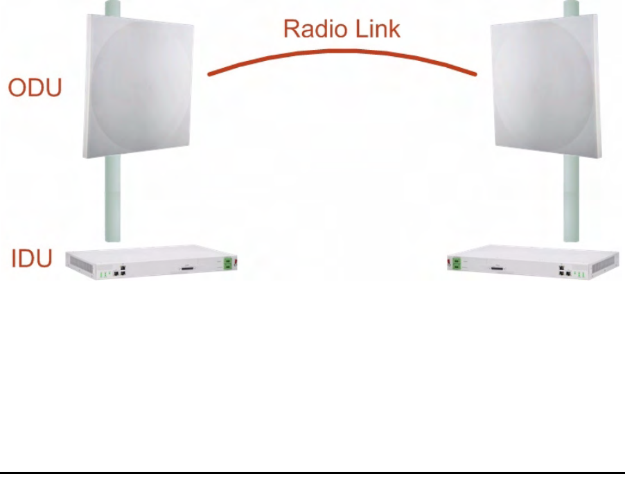
The RADWIN 1000/2000/3000 point-to-point solution is a wireless commu-
nication link. Typically each side of the link is comprised of an Outdoor Unit
(ODU) and antenna and an Indoor Unit (IDU) or PoE device as shown in
figure 1-4 below.
The link is managed by the SNMP-based RADWIN Manager application.
The IDU and the ODU are connected by a CAT5e cable that carries the ser-
vice traffic and power.
Figure 1-4: Example of Link Architecture - System Components
The Radio Outdoor Unit (ODU)
The ODU is the radio transceiver of the RADWIN 1000/2000/3000 system.
It supports two radios for MIMO operation. It is available with an integrated
antenna (
Integrated Antenna ODU
) or with connectors for an external
antenna (
Connectorized ODU
).
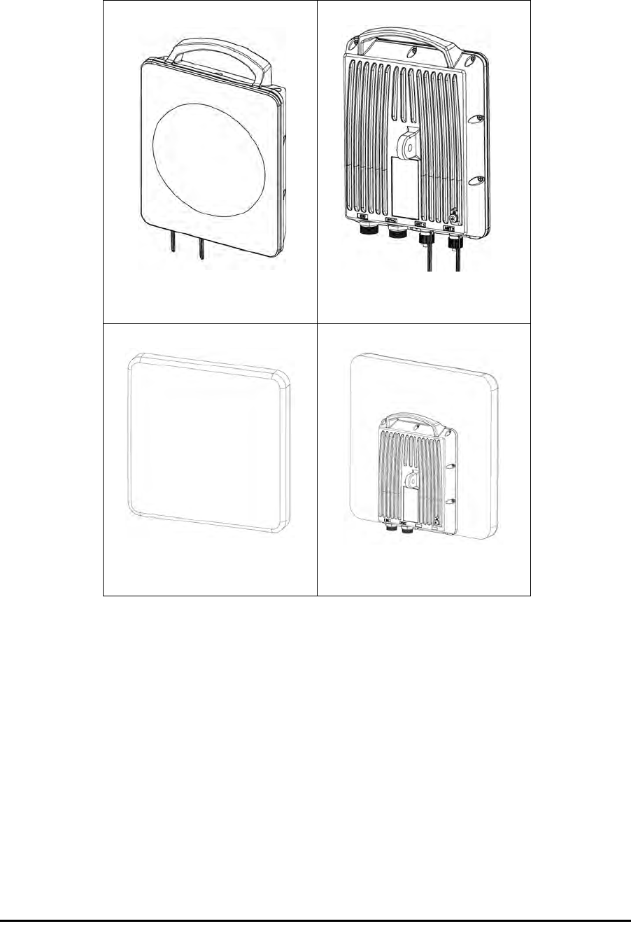
The Radio Outdoor Unit (ODU) Chapter 1
RADWIN 1000/2000/3000 User ManualVersion 2.5.30p1 1-6
The ODU may be mounted on a pole or a wall, and connects to the IDU or
PoE device using a CAT5e cable.
The ODU comes in two form factors as shown in figure 1-5 below:
Figure 1-5: ODU Form Factors
• Integrated Antenna ODU
This ODU has an integrated 370mm (1.2ft) flat panel antenna, with
a gain of 23dBi. The ODU contains both the radio and the antenna
as a single unit housed in a weatherproof case.
•Connectorized ODU
This ODU has 2x N-type connectors for connecting an external
antenna.
a. Connectorized ODU -
Front b. Connectorized ODU -
Rear
c. Integrated Antenna ODU
- Front d. Integrated Antenna ODU
- Rear

The Indoor Units (IDU) Chapter 1
RADWIN 1000/2000/3000 User ManualVersion 2.5.30p1 1-7
The ODU products available in release 2.5.30p1 are shown below:
The only available external antenna is, single bipolar.
For further information, see page 4-20, Installing the Link: Step 4, Tx
Power and Antenna Settings.
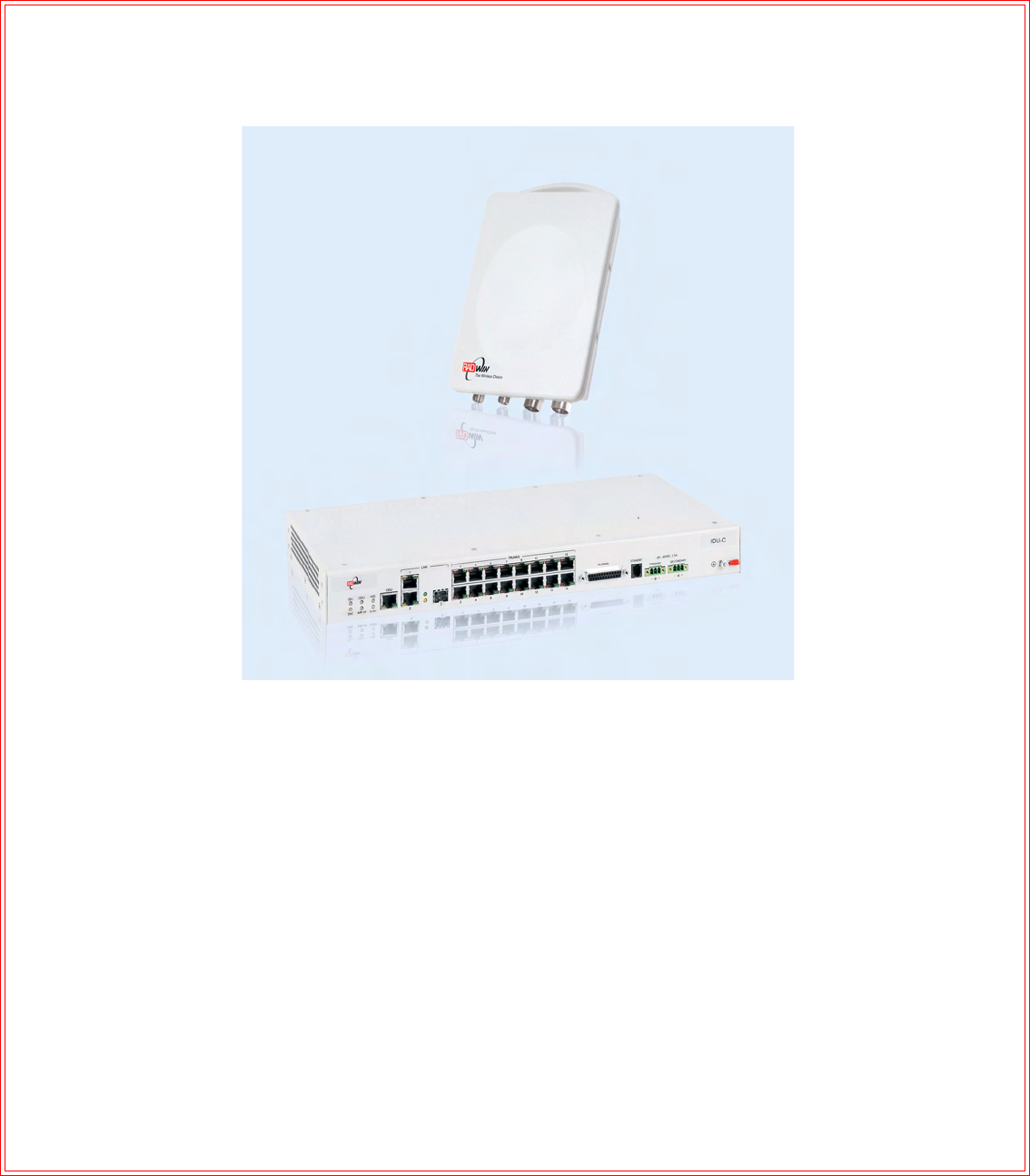
The Indoor Units (IDU)
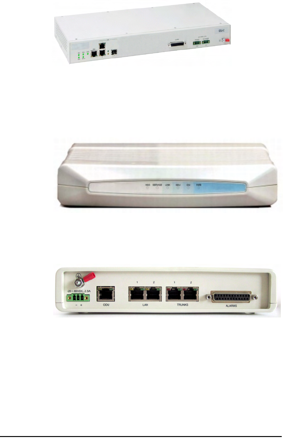
IDU-C
The IDU-C has the service ports and provides aggregation of these services
towards the ODU that transports them over the air. The IDU-C also provides
power to the ODU.
The IDU-C is a carrier-class 19 inch, 1U unit, providing two Ethernet ports,
dry contact alarms and indication LEDs. It has two DC power feed connec-
tors. An AC to DC converter is available for powering the IDU-C from an AC
source. The IDU-C is designed to be rack mounted.
One IDU-C product is available in release 2.5.30p1:
Table 1-1: Available ODU Products - Release 2.5.30p1
Part Number Description
Form Factor Frequency Bands and Regulations
RW-2050-0150 Integrated antenna FCC/IC5.725 – 5.850 GHz
FCC/IC5.250 – 5.350 GHz
FCC/IC5.470 – 5.725 GHz
FCC/IC4.940 – 4.990 GHz
FCC/IC2.400 – 2.4835 GHz
RW-2050-0250
Connectorized for external
antenna (2x N-type)
RW-2020-0150
RW-1020-0150 Integrated and connectorized
antenna (2x N-Type) FCC/IC2.400 – 2.4835GHz
RW-1030 series
RW-2030 series
RW-2030 series
FCC/IC3.650 – 3.700GHz
IC3.475 – 3.650GHz
Table 1-2: Release 2.1 IDU-C Products
Part Number Ethernet
ports Power Form
factor
7200-2000 2Dual DC feed
-20 to -60VDC 19" 1U
Power Over Ethernet (PoE) Devices Chapter 1
RADWIN 1000/2000/3000 User ManualVersion 2.5.30p1 1-8
Figure 1-6: IDU-C Front Panel
IDU-E
The IDU-E is a carrier grade, compact, half 19 inch wide, 1U plastic unit,
providing up to two Ethernet ports and up to two E1/T1 interfaces. It offers
Layer 2 support for Ethernet service and HSS support for collocated links. It
is a low cost unit intended for both Access applications and Enterprise use.
Figure 1-7: IDU-E - front view
The IDU-E rear panel (right to left) has a 25 pin Dry Contact Alarms port.
the two (or no) trunk ports, two LAN ports, an ODU port and finally a 3 pin
DC power plug identical to that used on the IDU-C.
Figure 1-8: IDU-E: Rear panel
Power Over Ethernet (PoE) Devices
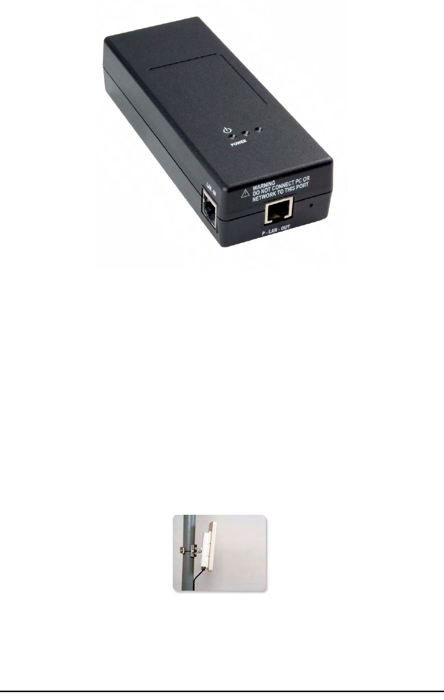
The PoE device provides Ethernet service only, with power for the ODU. The
PoE device is extremely compact, having only two Ethernet ports and a
standard 3 pin male AC power socket.
Antennas Chapter 1
RADWIN 1000/2000/3000 User ManualVersion 2.5.30p1 1-9
Figure 1-9: PoE device - showing the radio Ethernet port
Antennas
An antenna is the radiating and receiving element from which the radio sig-
nal, in the form of RF power, is radiated to its surroundings and vice versa.
The antenna gain and transmitting power may be limited by country regula-
tions.
The RADWIN 1000/2000/3000 may be operated with an integrated antenna
that is part of the ODU unit, or with external antennas connected to the
ODU via N-type connectors. All cables and connections must be connected
correctly to reduce RF losses. The required antenna impedance is 50Ω.
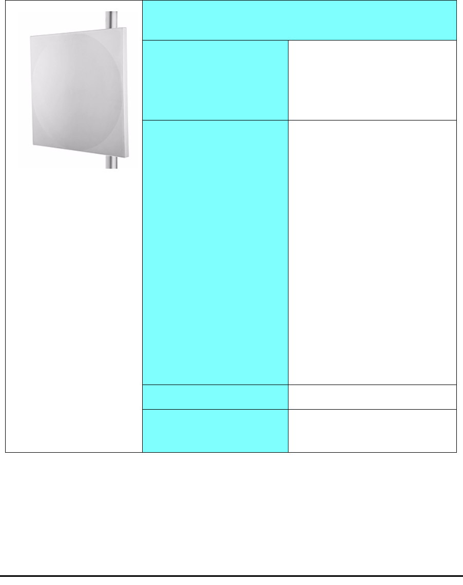
The Integrated Antenna ODU is provided with 370 mm (1.2ft) flat panel
antenna. The radio and the antenna are housed in a weatherproof case as a
single unit.
Figure 1-10: ODU with integrated Flat Panel antenna
External antennas are available for the RADWIN 1000/2000/3000 radios,
varying in operating frequencies, form factor, size and gain, dual or single
polarization.
Antennas Chapter 1
RADWIN 1000/2000/3000 User ManualVersion 2.5.30p1 1-10
The RADWIN 1000/2000 operating in frequency bands 5.3, 5.4, 5.8 GHz can
utilize external antennas with RF feeder cables that produce 6 dBi mi-nimal
assembly gain.
The RADWIN 1000 3GHz Band / RADWIN 2000 3GHz Band / RADWIN 3000
3GHz Band operating in the 3.5 and 3.65 GHz can utilize external antennas
with RF feeder cables that produce 13.5 dBi minimal assembly gain.
Flat Panel Antennas
The Flat Panel antenna shown in figure 1-11 below has an integrated or
external configuration:
Figure 1-11: Flat Panel Antenna
Integrated or External
1.2ft Flat Panel Dual Polarization
Frequency
4.9 – 6.0 GHz
2.4 – 2.7 GHz (Ext)
2.3 – 2.7 GHz (Int)
3.3 – 3.8 GHz (Int/Ext)
Gain
External
21 dBi at 4.9 – 5.0 GHz
22 dBi at 5.0 – 5.15 GHz
23 dBi at 5.15 – 6.0 GHz
20 dBi at 2.4 – 2.7 GHz
22 dBi at 3.3 – 3.8 GHz
Integrated
21 dBi at 4.9 – 5.0 GHz
22 dBi at 5.0 – 5.15 GHz
23.5 dBi at 5.15 – 5.725 GHz
24 dBi at 5.725 – 6.0 GHz
16.2 dBi at 2.3 – 2.4 GHz
17.5 dBi at 2.4 – 2.7 GHz
21 dBi at 3.3 – 3.8 GHz
Size 1.2 x 1.2 ft / 371x371 mm
Beam Width H, V: 9° (Ext)
H, V: 8° (Int)

RADWIN Manager Chapter 1
RADWIN 1000/2000/3000 User ManualVersion 2.5.30p1 1-11
Parabolic Dish Antennas
Figure 1-12: External Antennas - Parabolic Dish
See the RADWIN products catalog for RADWIN offering of external anten-
nas. External antennas are also available from authorized antenna vendors.
RADWIN Manager
The RADWIN Manager is an SNMP-based management application which
manages a complete link over a single IP address. It can also manage each
side of the link separately.
The RADWIN Manager application facilitates installation and configuration
of the link between the ODU units. The intuitive, easy-to-use RADWIN Man-
ager has a graphical Microsoft Windows interface, and can be run locally
and remotely.
The RADWIN Manager provides:
• Installation Wizard
• On-line monitoring of air interface quality allowing the administrator
to monitor the service and status of each link
• On-line monitoring of equipment alarms and QoS
• Local and remote loopback testing
• Configuration settings
• On-line user manual and help files
• Link Budget Calculator for calculating the expected performance of
the RADWIN 1000/2000/3000 wireless link and the possible service
configurations for a specific link range.
The RADWIN Manager can easily be integrated with any NMS system.
External
2ft Dish Dual Polarization
Frequency
5.150 - 5.875 GHz
4.900 – 5.850 GHz
3.300 – 3.800 GHz
Gain 28 dBi
25 dBi (3.5/3.65GHz)
Diameter 2 ft / 620 mm
Beam Width H,V: 5.6°
Accessories Chapter 1
RADWIN 1000/2000/3000 User ManualVersion 2.5.30p1 1-12
Figure 1-13: RADWIN Manager screen
Accessories
RADWIN provides a variety of accessories to support the RADWIN 1000/
2000/3000 system:
•PoE devices
•AC Power Adaptor
• External Lightning Protection Unit
• Cables to connect the various system elements
Documentation set supplied with RADWIN 1000/2000/
3000
The technical documentation supplied with a RADWIN 1000/2000/3000
includes the following items:
• A Quick Start Guide for experienced installers
• A full User Manual - the document which you are reading

How to Use this Manual Chapter 1
RADWIN 1000/2000/3000 User ManualVersion 2.5.30p1 1-13
How to Use this Manual
This User Manual is divided into functionally distinct chapters reflecting the
activities required to set up a RADWIN 1000/2000/3000. The division is
shown in the following table:
A Little Terminology
In the field, a link typically has a local or headquarters site as for example in
figure 1-2 above. Here the service provider is the local or headquarters
site. The service recipient is the remote site.
Where the link is completely internal to a corporation, the choice of the local
and remote is just a matter of convenience.
Chapter/
Appendix Subject Audience
2 Site Preparation Site survey team
3 Hardware Instal-
lation Field technician
4 Link Installation:
The RADWIN Man-
ager
Installation technician
5Configuring the
Link Installation technician, System manager
6 Site Configuration Installation technician, System manager
7 Monitoring and
Diagnostics Installation technician, System manager
A Technical Specifi-
cations Installation technician, System manager
B Wiring Specifica-
tions Installation technician
C Pole and Wall
Installation Installation technician
D Link Budget Cal-
culator Installation technician
E Lightning Protec-
tion and Ground-
ing Guidelines
Field technician
FMIB Reference
System manager
GExternal Alarms
Specification Installation technician, System manager,
Field technician
H Combo Configura-
tion Tool Installation technician

A Little Terminology Chapter 1
RADWIN 1000/2000/3000 User ManualVersion 2.5.30p1 1-14
A
link
then, consists of two
sites
.
In Broadband Wireless terminology, the local and remote sites are some-
times referred to as “near” and “far”, “HQ” and “remote” and so on.
The site which is closer to the network core (often the local site) will be
referred to as
site A
, and the opposite side of the link, usually closer to the
end user, as
site B
.
This choice is application-neutral and will be used throughout the manual
both to describe the sites and their names as in the examples.
The link is configured and managed using a PC, the
managing computer
connected to site A. (The precise requirements for the managing computer
are set out in chapter 3, Hardware Installation).
RADWIN 1000/2000/3000 supports three connection methods for the man-
aging computer:
•
Local
- a direct peer to peer connection between the Ethernet ports
on the managing computer and the IDU or PoE device. Local con-
nection is always read-write.
•
Network
- the managing computer and the site A IDU or PoE
device belong to a LAN and communicate through a router or hub
•
Over-the-air
- the managing computer connects to site B via the
air interface
The managing computer may be connected to the link through an IDU or a
PoE device. In what follows, where ever we refer to an IDU it includes PoE
devices unless stated otherwise. Typically, if we need to refer to an IDU as
such, we will use a model name such as IDU-C.
Conventions Used in this Manual Chapter 1
RADWIN 1000/2000/3000 User ManualVersion 2.5.30p1 1-15
Conventions Used in this Manual
Notifications
Notifications consist of Notes, Cautions and Warnings.
Typographical conventions
General
Where a term is defined or introduced for the first time, it is shown in Bold-
face. You will have noticed this usage in the Terminology section above.
Software
The RADWIN Manager is a Microsoft Windows application following the user
interface conventions of familiar Microsoft Windows programs.
We would describe the chain of menu commands indicated in the following
screen shot, like this:
Tools|Active Alarms|1 A
Note
The purpose of a Note is to
• Draw your attention to something that may not be obvious or coun-
ter-intuitive
• Emphasize a special feature or peculiarity of the RADWIN 1000/2000/
3000
• Offer an external reference for additional information
• Add a caveat that would not qualify as a full Caution or Warning (see
below)
• Provide additional background to what follows
• Offer a recommendation
• Highlight an indication of something to watch out for
• Advise you if an action has “side effects” i.e. it may disturb something
else that would be best left undisturbed
• Remind you of something that should be kept in mind
Caution
A Caution is a notification of risk of damage to equipment or of service
degradation
Warning
A Warning is a notification of risk of danger to persons operating near the
equipment

Windows Terminology Chapter 1
RADWIN 1000/2000/3000 User ManualVersion 2.5.30p1 1-16
using Boldface for the menu labels and vertical bars to separate them.
Similarly, mouse click items will be referred to like this:
“Click Next to continue.”
(A mouse click always uses the left mouse button unless stated otherwise.)
Windows Terminology
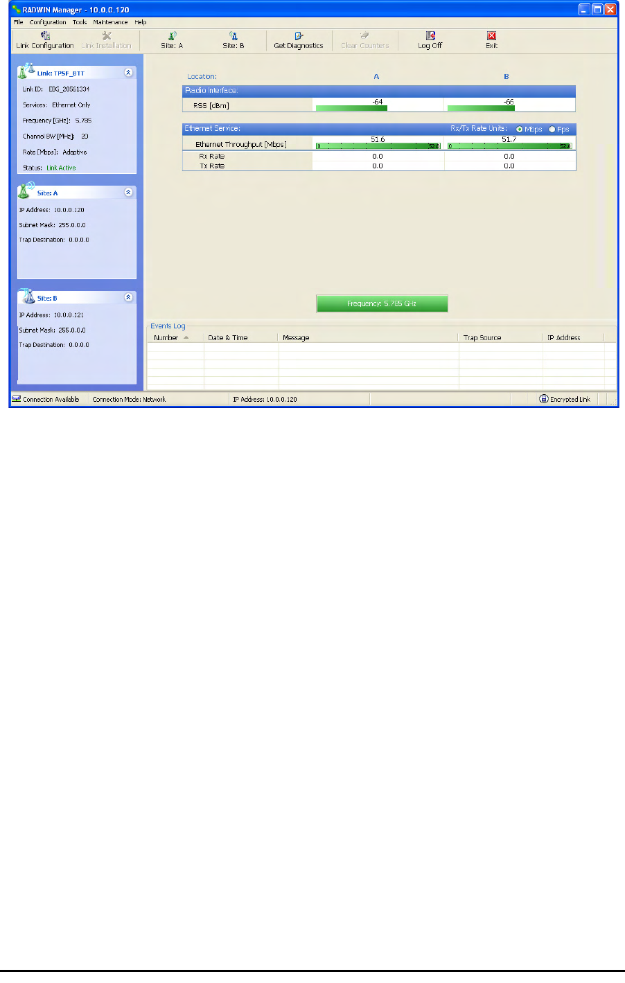
Look at figure 1-13 above. The main application display which you see
consists of a frame-window with a menu bar, system icons and content. It
will be referred to as a window, the main window or the Manager win-
dow depending on context.
The top line of icons is the tool bar, and provides part of the menu bar
functionality with a mouse click.
At the bottom of the window is the status bar, a line of icons and text
boxes.
The central part of the main window consists of several panes: On the
right, there are Radio Interference, Ethernet Service and the Frequency
panes. The left hand pane (with the blue background) is split into three
sub-panes.
If you click Site A or Site B in the tool bar, you will be offered another win-
dow, which in turn displays on of several panels depending on which func-
tion you choose.
Windows Terminology Chapter 1
RADWIN 1000/2000/3000 User ManualVersion 2.5.30p1 1-17
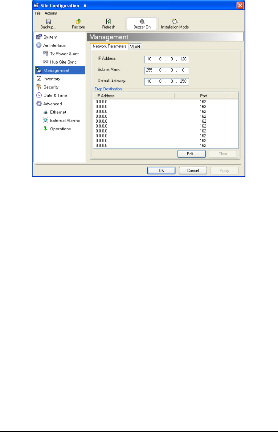
Figure 1-14: Site Configuration window with open Management panel

RADWIN 1000/2000/3000 User ManualVersion 2.5.30p1 2-1
Chapter 2
Site Preparation
Planning the Link Site
Overview
Link site planning consists of a set of surveys, which must be carried out
before any equipment is brought to the site. If for some reason, the out-
come of any of these surveys is negative, site re-location will need to be
considered.
A Site Survey consists of three stages:
1. Preliminary survey - The proposed link is analyzed in the office using a
topographic map.
2. Physical survey - The locations of the RADWIN 1000/2000/3000 indoor
and outdoor equipment are determined on-site.
3. Radio Frequency (RF) survey - It is recommended that the installation
area be scanned with a spectrum analyzer, to identify RF interference so
as to determine a clear channel for RADWIN 1000/2000/3000 installation
(on-site).
The Site Survey
Introduction
RADWIN 1000/2000/3000 wireless links must be planned before installa-
tion. The designated installation site must be appraised to determine that
the wireless system is able to operate efficiently and provide connectivity
without signal degradation.
RADWIN 1000/2000/3000 offers a wide operating frequency range. A free
frequency channel must be determined within the operating range, for opti-
mum performance.
Recommended Equipment
Stage 1: Preliminary Survey
• Topological map of the area

Stage 1: Preliminary Survey Chapter 2
RADWIN 1000/2000/3000 User ManualVersion 2.5.30p1 2-2
• Urban map of the area
•Compass
Stage 2: Physical Survey
• 100 meter tape measure
• Ohmmeter, to check ground connection
•Binoculars
•Map
• Digital camera
• Paper, pencil, and a clipboard
• GPS device (optional)
• Compass (optional)
Stage 3: RF Survey
• Spectrum Analyzer with Max Hold function and screen capture facil-
ity that can store multiple images, for documentation purposes
• RF accessories (connectors and cables)
• Communication devices (for example, cellular phones, or a set of
walkie-talkies)
Stage 1: Preliminary Survey
A preliminary survey is necessary before visiting potential installation sites.
As much detail as possible should be obtained about the two designated
ODU installation sites and the area between them.
¾To perform a preliminary survey:
1. Mark the two designated installation sites on a topographic map of the
area.
2. Measure the distance between the sites; check that it is within the speci-
fied range of the RADWIN 1000/2000/3000.
3. On the urban map, check for developed areas situated between the two
installation sites. Pay attention to these areas when performing the phys-
ical site survey; there may be tall buildings, RF towers, or transmitters,
which could cause interference to the link.
4. Check the area between the two sites for obstructions such as:
• High ground - hills or mountains
• Lakes or large bodies of water. Water has a reflection effect on RF
signals like a building. This type of reflection causes the received
amplitude to be reduced. As a rule of thumb, the presence of a large
body of water between the link sites may double the required
antenna height.
5. Determine and record the compass bearings between both ODUs, rela-
tive to north.
6. If there are obstructions between the two sites, calculate the Fresnel
Zone (see appendix D for details).

Stage 2: Physical Survey Chapter 2
RADWIN 1000/2000/3000 User ManualVersion 2.5.30p1 2-3
7. If the site chosen does not meet requirements, consider alternative sites.
8. Use the Link Budget Calculator (on the CD supplied with the RADWIN
1000/2000/3000 or using the RADWIN Manager) to determine the
expected performance.
Stage 2: Physical Survey
The physical site survey reviews the environment of the proposed RADWIN
1000/2000/3000 installation location, to ensure that the link sites are suit-
able for the wireless network. The results of the physical site survey should
be recorded.
¾To perform a physical survey:
1. From the compass readings taken in the preliminary survey, find the azi-
muth (horizontal position) that the ODU should face towards the second
ODU.
2. Using binoculars, locate any obstructions such as tall trees, high build-
ings, hills or mountains. Look for other RF towers between the two sites.
Mark the locations of the obstructions on the map.
3. Determine the location for the ODU (having regard for existing rooftop
installations and tower space). It should be above any obstructions, con-
sidering the Fresnel zone (see appendix D).
4. If you need to install the ODU on a tower, make sure that the tower is far
away from overhead electric power lines.
5. Determine a location for the indoor equipment; it should be as close as
possible to the ODU. At an existing site, there is probably an equipment
room with cable-routing channels.
6. Measure and record the path length of the cable from the ODU position
to the indoor equipment room.
7. Determine the ground and lightning connection points of the installation.
The RADWIN 1000/2000/3000 ODU and IDU must both be grounded.
8. Using the Ohmmeter, measure and record the resistance of the required
installation to the grounding point. The resistance must be less than 1O
ohm.
Note
It is advisable to go on a clear day, so you can more easily see any
obstructions between the two sites.
Note
The IDU - ODU cable length limit is 100m, in accordance with IEEE 10/
100BaseT standards.

Additional Outdoor Site Requirements Chapter 2
RADWIN 1000/2000/3000 User ManualVersion 2.5.30p1 2-4
9. Review the results of the physical site survey. Decide if the site is suitable
for the RADWIN 1000/2000/3000 wireless network installation.
• If the site is suitable, continue with stage 3, the RF survey
• If the site is not suitable, survey another site
Additional Outdoor Site Requirements
The ambient outdoor operating temperature should be -35 to 60°C (-31 to
140°F).
Additional Indoor Site Requirements
The following requirements guarantee proper operation of the system:
• For IDU-C units, allow at least 90 cm (36 “) of front clearance for
operating and maintenance accessibility. Allow at least 10 cm (4 “)
clearance at the rear of the unit for signal lines and interface cables
• The ambient operating temperature should be 0 to 50°C (32 to 122
°F) at a humidity of up to 90%, non condensing
Stage 3: RF Survey
The RF survey examines the wireless environment of the RADWIN 1000/
2000/3000 installation site, to determine whether there are available chan-
nels within the RADWIN 1000/2000/3000 operating frequency band. An RF
survey is performed using a spectrum analyzer.
It is advisable to familiarize yourself with the spectrum analyzer before
going out on site, specifically the Max Hold and Marker functions.
You should perform the RF survey at both proposed link sites.
The survey should be carried out during a busy time of day, to best judge
the worst-case radio interference. Allow 2-4 hours duration for a good RF
survey.
Note
It is possible to install the RADWIN 1000/2000/3000 link and use the
RADWIN Manager to find a clear channel. Each frequency channel can be
evaluated in turn. Achievement of a clear channel is indicated by the Quality
bar on the Channel Setting window (see figure 4-13) becoming green.

RADWIN 1000/2000/3000 User ManualVersion 2.5.30p1 3-1
Chapter 3
Hardware Installation
This chapter sets out the requirements and procedures for the hardware
installation and alignment of a RADWIN 1000/2000/3000 link in accordance
with the prior planning as set out in chapter 2. It is intended to guide quali-
fied field technicians.
Safety Practices
Preventing overexposure to RF energy
To protect against overexposure to RF energy, install the ODUs so as to pro-
vide and maintain minimal separation distances from all persons.
When the system is operational, avoid standing directly in front of the
antenna. Strong RF fields are present when the transmitter is on. The ODU
must not be deployed in a location where it is possible for people to stand
or walk inadvertently in front of the antenna.
Grounding
All RADWIN products should be grounded during operation. In addition:
•The ODU should be earthed by a wire with diameter of at least
12AWG.
The RADWIN 1000/2000/3000 ODU must be properly grounded to
protect against lightning. It is the user's responsibility to install the
equipment in accordance with Section 810 of the National Electric
Code, ANSI/NFPA No.70-1984 or Section 54 of the Canadian Electri-
cal Code. These codes describe correct installation procedures for
grounding the outdoor unit, mast, lead-in wire and discharge unit. It
Warning
Outdoor units and antennas should be installed ONLY by experienced
installation professionals who are familiar with local building and safety
codes and, wherever applicable, are licensed by the appropriate
government regulatory authorities. Failure to do so may expose the end
user or the service provider to legal and financial liabilities. RADWIN and its
resellers or distributors are not liable for injury, damage or violation of
regulations associated with the installation of outdoor units or antennas.

Protection against Lightning Chapter 3
RADWIN 1000/2000/3000 User ManualVersion 2.5.30p1 3-2
also lays down the size of grounding conductors and connection
requirements for grounding electrodes.
The RADWIN 1000/2000/3000 ODU must be grounded to a Protec-
tive Earth as described in appendix E and in accordance with the
Local Electrical Regulations.
• The earth lug on the IDU-C and IDU-E should be connected to the
protective earth at all times, by a wire with a diameter of 18 AWG
or wider. Rack-mounted equipment should be mounted only in
earthed racks and cabinets.
Further, you should -
• Always make the ground connection first and disconnect it last
• Never connect telecommunication cables to ungrounded equipment
• Ensure that all other cables are disconnected before disconnecting
the ground
More detailed guidelines are supplied in appendix E.
Protection against Lightning
The use of lightning protection is dependent on regulatory and end user
requirements. All of RADWIN outdoor units are designed with surge limiting
circuits to minimize the risk of damage due to lightning strikes. RADWIN
recommends the use of additional surge arrestor devices to protect the
equipment from nearby lightning strikes.
See appendix E for detailed installation instructions of lightning protection
devices.
General
• It is recommended that installation of the outdoor unit be contracted
to a professional installer.
• Before working on equipment connected to power lines or telecom-
munication lines, you should remove jewelry or any other metallic
object that may come into contact with energized parts.
• Use extreme care when installing antennas near power lines.
• Use extreme care when working at heights.
• When using an AC power source for RADWIN 1000/2000/3000
always use the AC power adapter supplied by RADWIN.
• Use the right tools. In addition to standard tools required for any
kind of ODU or antenna installation, RADWIN 1000/2000/3000
requires additional specific tools detailed on page 3-5 below.
Package Contents
The RADWIN 1000/2000/3000 packages include the following items:
ODU Package Contents
The ODU package contains:
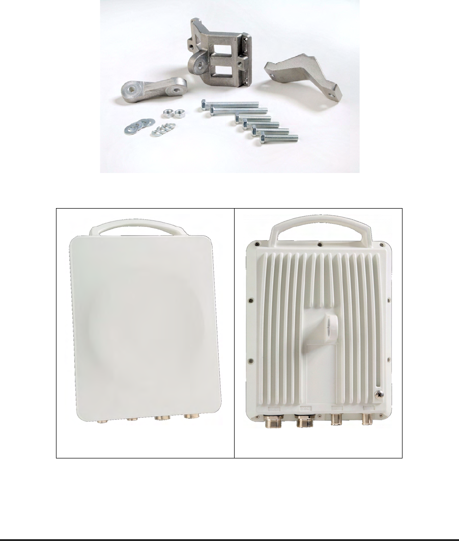
ODU Package Contents Chapter 3
RADWIN 1000/2000/3000 User ManualVersion 2.5.30p1 3-3
• One ODU - see figure 3-2 below for front and rear view
• An ODU mounting kit - see figure 3-1 below
• A CD containing -
• the RADWIN Manager
•Quick Start Guide
• User Manual
• Link Budget Calculator
• Label showing the MAC address and the alternative Community
string. The label is self-adhesive. You should keep this label safe
• Cable glands (to be used with the ODU-IDU cable)
Figure 3-1: ODU Mounting kit
Figure 3-2: Connectorized ODU - Front and rear views
ODU - Front View ODU - Rear View
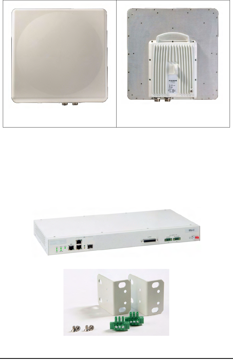
IDU Package Contents Chapter 3
RADWIN 1000/2000/3000 User ManualVersion 2.5.30p1 3-4
Figure 3-3: Integrated ODU - Front and rear views
IDU Package Contents
The IDU package contains:
• IDU-C - see figure 3-4 below.
• 19” rack mounting kit - see figure 3-5 below
• Two DC power plugs for power cables - see figure 3-5 below
Figure 3-4: IDU-C Package contents - the IDU-C
Figure 3-5: IDU-C Package contents - the mounting kit and DC power plugs
ODU - Front View ODU - Rear View

External Antenna Package Contents Chapter 3
RADWIN 1000/2000/3000 User ManualVersion 2.5.30p1 3-5
External Antenna Package Contents
•Antenna
• RF cable 1m (3’) long; two cables supplied with bipolar antennas,
single cable supplied with monopolar antennas
• Mounting kit
Additional Tools and Materials Required
The following is a list of the equipment and materials required to install
RADWIN 1000/2000/3000 hardware.
Tools and Materials
• Crimping tool for RJ-45 (if the ODU-IDU cable is without connectors)
• Spanner/wrench 13 mm (½”)
• Drill (for wall mounting only)
•Cable ties
• Sealing material
Cables and connectors
• ODU grounding cable 12AWG
• IDU grounding cable 18AWG
• ODU-IDU cable (outdoor class, CAT-5e, 4 twisted pairs, 24AWG)
Hardware Installation Sequence
The following steps are required to install the RADWIN 1000/2000/3000
system:
1. Mounting the ODUs, page page 3-6.
2. Mounting the external antennas (if used), page page 3-7.
3. Mounting the Lightning Protection devices (if used), page page 3-7.
4. Outdoor connections, page page 3-8.
5. Mounting the IDUs, page page 3-8.
6. Indoor connections, page page 3-12.
7. Aligning the ODUs/antennas, page page 3-13.
See figure 3-6 below, which illustrates a typical installation of RADWIN
1000/2000/3000 with an external antenna.
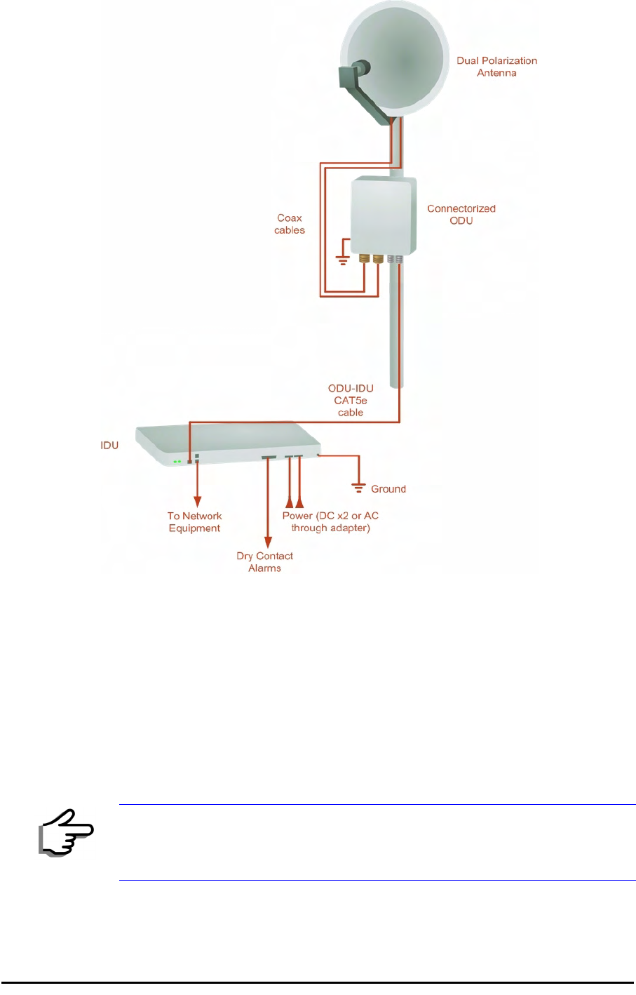
Outdoor installation Chapter 3
RADWIN 1000/2000/3000 User ManualVersion 2.5.30p1 3-6
Figure 3-6: Typical Installation Diagram (with external antenna)
The installation steps are detailed in the following sections.
Outdoor installation
Mounting the ODU
The ODU can be mounted on a pole or a wall. In both installations, the sup-
plied mounting kit is used to secure the ODU.
A RADWIN 1000/2000/3000 link operates in pairs of two ODUs with the
same configuration. Both ODUs must be installed, and the antennas aligned
for maximum throughput.
Note
A mast-sited ODU typically uses a pole attached to the mast.

Mounting external antennas Chapter 3
RADWIN 1000/2000/3000 User ManualVersion 2.5.30p1 3-7
¾To mount the ODU on a pole or a wall:
1. Ensure that the ODU is properly grounded.
2. Mount the ODU onto the pole or wall. Ensure that the unit is oriented so
that the cable connectors are at the bottom. (If they are on top,
water may penetrate into the unit causing damage.)
3. Refer to Appendix C, Pole and Wall Installation for detailed ODU
mounting kit contents and schematics.
Mounting external antennas
If you are using ODU with an integrated antenna, skip to Mounting the
Lightning Protection Devices below.
The supplied mounting kit is used to mount the antenna onto a pole. The
antennas must be aligned for maximum throughput.
¾To mount an external antenna:
1. To mount an external antenna ensure that the antenna is properly
grounded and then mount the antenna onto the pole. Refer to Appen-
dix C, Pole and Wall Installation for detailed antenna mounting
instructions.
2. Follow the mounting instructions supplied with the antenna.
Mounting the Lightning Protection Devices
The use of lightning protection is dependent on regulatory and end user
requirements. The RADWIN 1000/2000/3000 ODU is designed with surge
limiting circuits to minimize the risk of damage due to lightning strikes.
Warning
Prior to connecting cables to the ODU, the protective earth terminal (screw)
of the ODU must be connected to an external protective ground conductor
or to a grounded pole.
• Only a qualified person using the proper safety equipment should
climb the antenna mast
• Only qualified professional personnel should install or dismantle
ODUs and masts
Note
Do not tighten the ODU to its mounting brackets until the alignment
process of the antenna is complete.
Ensure that there are no direct obstructions in front of the ODU or
interference from man-made obstacles.
Warning
Do not stand in front of a live antenna.
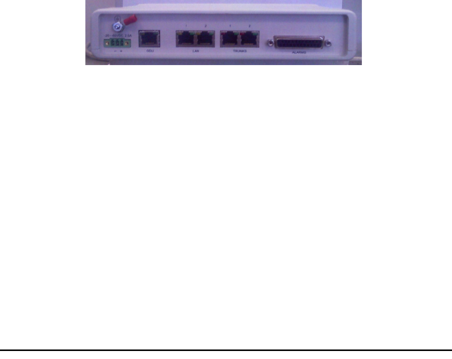
Outdoor Connections Chapter 3
RADWIN 1000/2000/3000 User ManualVersion 2.5.30p1 3-8
RADWIN recommends the use of additional surge arrestor devices to pro-
tect the equipment from nearby lightning strikes.
Refer to appendix E for detailed installation instructions of lightning protec-
tion devices.
Outdoor Connections
¾To complete the outdoor connections:
1. Connect the ground cable to the ODU chassis as marked on the ODU.
2. Connect the antenna cable(s) to the ODU.
3. Connect the lightning protection device to the ODU (see appendix E).
4. Attach the ODU-IDU cable to the ODU RJ-45 connector (see appendix B
for the connector pin-out)
5. Screw in the cable glands to ensure hermetic sealing of the ODU.
6. Secure the cables to the pole, mast or brackets using UV-rated cable ties.
Indoor Installation
IDU-E Installation
The IDU-E can be wall mounted, placed on a desktop or take up one half of
a 1U rack slot. The unit should be grounded, cabled to the ODU and con-
nected to power using the supplied AC/DC adapter.
Figure 3-7: New style IDU-E: Rear panel
Mounting the IDU-C
The RADWIN 1000/2000/3000 IDUs are all rack mounted, as shown in
figure 1-6. A front panel keyed schematic of a rack mounted IDU-C is
shown in figure 3-8 below.
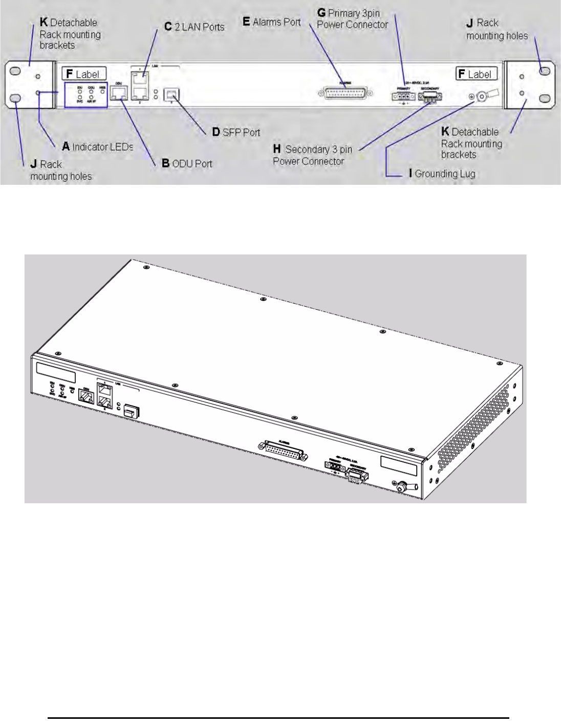
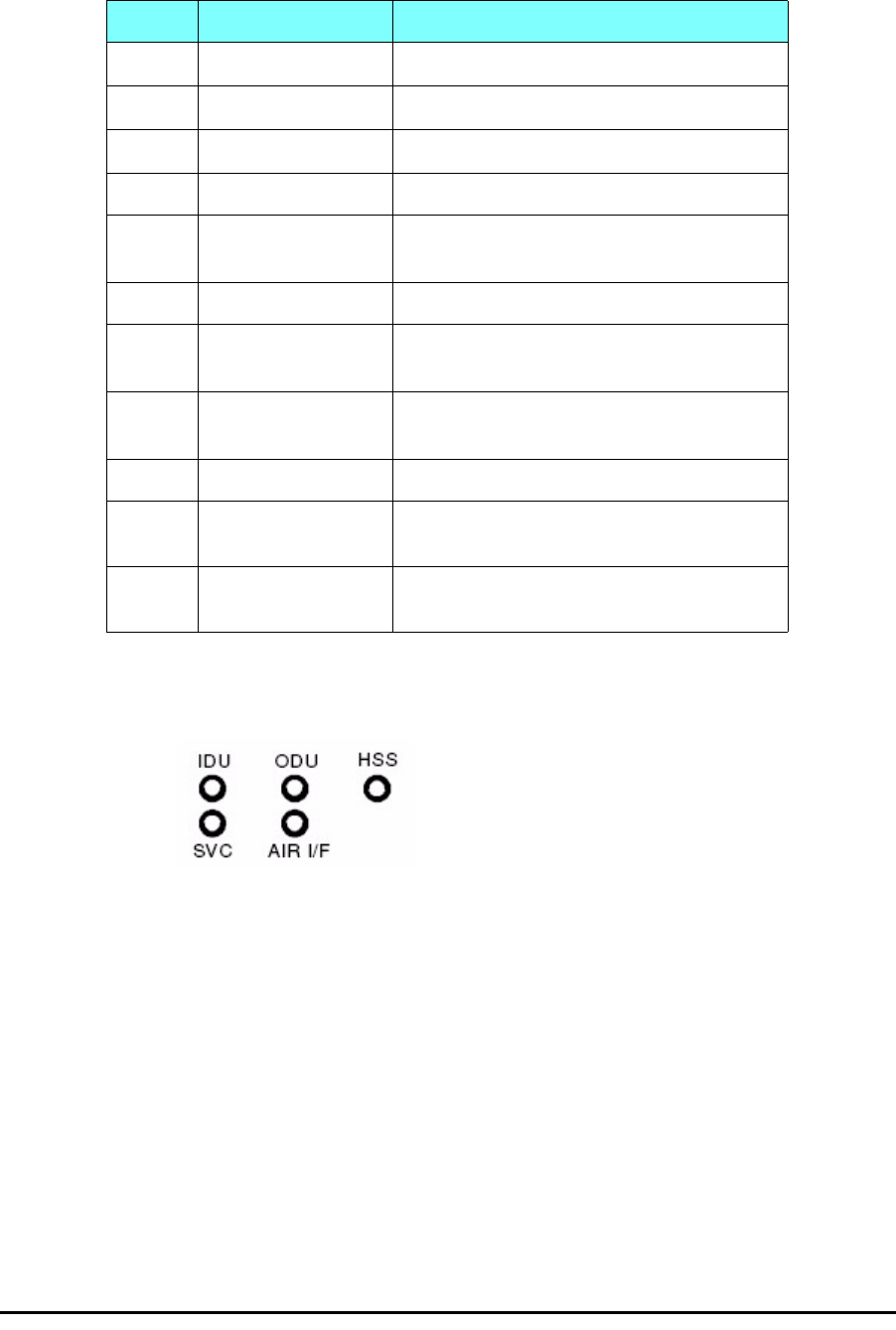
Mounting the IDU-C Chapter 3
RADWIN 1000/2000/3000 User ManualVersion 2.5.30p1 3-10
Further description of the keyed items in figure 3-8 is shown in table 3-1
below:
The Indicator LEDs (Item A in table 3-1 above) are shown in more detail in
figure 3-10 below:
Figure 3-10: IDU-C LEDs
Table 3-1: Components of an IDU-C front panel
Key Label Remarks
A Indicator LEDs See figure 3-10.
BODU Port RJ-45 connector, see table B-1.
C2 LAN Ports Ethernet, RJ-45 connector, see table B-2
D SFP Port The IDU-C is SFP ready.
E Alarm Ports Standard DB25 female connector, see
table B-3.
F Label indent Place for adhesive identification labels
G Primary 3 pin Power
Connector Standard 3 pins in line power connector,
see table B-4.
H Secondary 3 pin
Power Connector Standard 3 pins in line power connector,
see table B-4.
I Grounding Lug Use the lug supplied
JRack mounting
holes
KDetachable Rack
mounting brackets

Connecting power to the IDU Chapter 3
RADWIN 1000/2000/3000 User ManualVersion 2.5.30p1 3-11
The purpose of the LEDs is shown in table 3-2 below:
¾To mount an IDU (using figure 3-8 above):
1. If the rack already holds other equipment, ensure that it is properly
grounded.
2. Attach the rack mounting brackets (K) to the IDU.
3. Bolt the IDU into an empty slot in the rack, ensuring that it sits securely.
4. Ground the IDU to the rack using grounding lug I. The IDU should be left
permanently grounded.
Connecting power to the IDU
The IDU-C has redundant power connection circuits (items G and H in
figure 3-8 above). An enlarged schematic of the power connectors is
shown in below:
Table 3-2: IDU-C Front Panel LEDs
Name Color Function
IDU Green
Green
Red
IDU operational
During power-up only
Failure
ODU Green
Red
ODU-to-IDU communication link is operating
ODU-to-IDU communication link is disrupted
AIR I/F Green
Orange
Red
Wireless link is synchronized
During installation mode only
Wireless link lost synchronization
SVC Off
HSS Off
Warning
Do not proceed with installation into a “live” rack unless it is properly
grounded.
Note
Instead of using the rack mounting brackets, the IDU may be rail mounted
using the four screw holes on each of its sides.

Connecting the ODU to the IDU Chapter 3
RADWIN 1000/2000/3000 User ManualVersion 2.5.30p1 3-12
Figure 3-11: DU-C ower connectors
The connectors are 3 pin in line female, with polarities (left to right) minus,
ground, plus. To avoid damage to the IDU, always use an AC/DC adapter
supplied by RADWIN.
Ensure that the IDUs at both sites are powered up.
Connecting the ODU to the IDU
The ODU-IDU cable conducts all the user traffic between the IDU and the
ODU, and also provides power to the ODU. The maximum length of the
ODU-IDU cable is 100m (328 ') in accordance with 10/100BaseT standards.
The ODU-IDU cable is supplied pre-assembled with RJ-45 connectors, at the
length specified when ordering, or as a cable drum with spare connectors. If
the ODU-IDU cable was not ordered, use an outdoor class, CAT-5e 24AWG
shielded cable. See appendix B for Wiring Specifications.
To connect the ODU to the IDU, route the cable from the ODU to the IDU,
secure the cable along its path and connect the cable to the ODU RJ-45
connector on the IDU (see item B in figure 3-8 above).
Installing a Link using PoE Devices
The PoE device is a very simple unit having a power input connector and
two Ethernet ports. It is AC powered, and has a power LED.
¾To prepare a link using PoE devices:
1. To connect the ODU to the PoE device, route the cable from the ODU to
the PoE device, secure the cable along its path and connect the cable to
the P-LAN-OUT RJ-45 connector on the PoE device.
2. Connect it to AC power.
3. Repeat steps 1 to 2 for the second link.
Connecting User Equipment
¾To connect user equipment to the IDU:
• Connect user switch/router or any other compatible device to the IDU
panel RJ-45 ports designated LAN (see item C in figure 3-8 above).

Connecting and Aligning ODUs / Antennas Chapter 3
RADWIN 1000/2000/3000 User ManualVersion 2.5.30p1 3-13
Refer to appendix B, Wiring Specifications, for connector pinouts.
¾To connect user equipment to the PoE device:
• Connect a user switch, router or any other compatible device to the PoE
device RJ-45 port designated LAN-IN. Refer to appendix B, Wiring
Specifications, for connector pinouts.
Connecting and Aligning ODUs / Antennas
You perform antenna alignment using the ODU's audible tone.
To speed up the installation time, alignment of a RADWIN 1000/2000/3000
system should be performed by two teams simultaneously, at site A and at
site B.
¾To align ODUs with integrated antennas or external bipolar antennas:
1. For external bipolar antennas: Using a coax cable with N-Type connec-
tors, connect the vertical polarization connector of the antenna to the
ANT 1 connector of the ODU.
2. For external bipolar antennas: Using a coax cable with N-Type connec-
tors, connect the horizontal polarization connector of the antenna to the
ANT 2 connector of the ODU.
3. Ensure that power is connected to the IDUs at both sites.
4. Ensure normal operation of the IDUs by the LED indications on the front
panel.
Provided that site A detects the signal from site B, the ODU starts beep-
ing 20 seconds after power up, and continues beeping until the ODUs are
aligned, and the installation is complete.
In the following steps, “antenna” refers both to an external antenna and
an integrated antenna.
5. Direct the antenna of site B in the direction of site A. This is simplified if
a previous site survey has been completed and azimuths are known.
6. Make a horizontal sweep of 180 degrees with the site A antenna so that
the strongest signal from site B can be detected.
Note
Do not connect two LAN ports to the same network, or flooding may occur.
Warning
When aligning the antennas, do not stand in front of a live antenna.
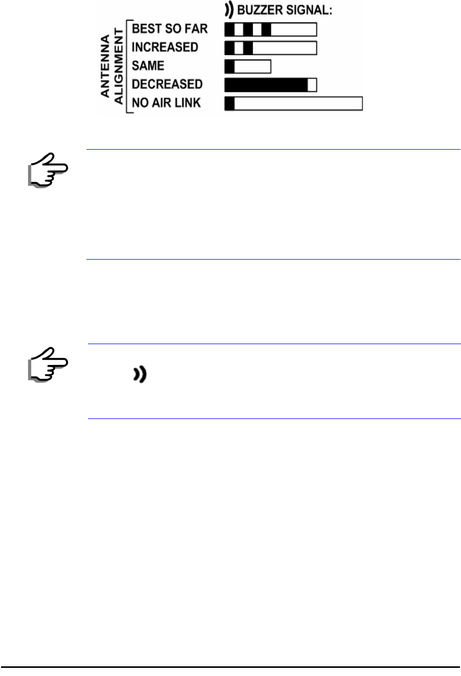
Connecting and Aligning ODUs / Antennas Chapter 3
RADWIN 1000/2000/3000 User ManualVersion 2.5.30p1 3-14
7. Slowly turn the site A antenna back towards the position of site B, listen-
ing to the tone until the best signal is reached. See the following figure
for audible signal variations.
Figure 3-12: Beep Sequence for antenna alignment
8. Secure the site A antenna to the pole/wall.
9. Repeat steps 4 to 8 for site B.
¾To align two external monopolar antennas:
1. Using a coax cable with N-Type connectors, connect one antenna to the
ANT 1 connector of the ODU.
2. Follow the steps 3 to 7 above to align the antenna connected to the ODU
connector ANT 1 on both sides of the link.
3. On both sides of the link, disconnect the antenna connected to the ODU
connector ANT 1. Connect the other antenna to connector ANT 1 and fol-
low the steps 3 to 7 above to align the second antenna.
4. Secure the antennas to the pole/wall.
5. Restore one of the antennas to ANT 2 on both sides of the link.
Note
• Three beeps and a pause is 'best signal so far'
• Two beeps and a pause is 'signal quality increased'
• One beep and pause is 'no change in signal'
• Long beep and short pause is 'signal quality decreased'
• One beep and a long pause is 'no air link'
• Any other signal does not relate to antenna alignment
Note
The ODU buzzer only works on the radio connected to the ANT 1 connector
marked . You will therefore need to use ANT 1 to align both antennas in
turn. Upon completion of the alignment procedure, you may connect the
two antennas to ANT 1 and ANT 2 connectors.

RADWIN 1000/2000/3000 User ManualVersion 2.5.30p1 4-1
Chapter 4
Link Installation: The
RADWIN Manager
This chapter explains how to use the RADWIN Manager to install a radio
link.
Installing theRADWIN Manager Application
Minimum System Requirements
The RADWIN Manager application is distributed on a CD. Operating system
specific PC resources required by the application are set out in table 4-1
below:
Requirements common to all systems are:
• Hard disk: 1 GB free space
• Network: 10/100BaseT NIC
• Graphics: 1024x768 screen resolution with 16 bit color
• Microsoft Explorer version 5.01 or later
Installing the Software
¾To install the RADWIN Manager application:
1. Insert the CD into the CD/DVD drive of your computer.
The CD opening screen appears:
Table 4-1: PC Requirements for the RADWIN Manager Application
Windows 2000 Windows XP Pro Windows Vista
Memory 128 MB 512 MB 1 GB
Processor P III P IV P IV Dual Core
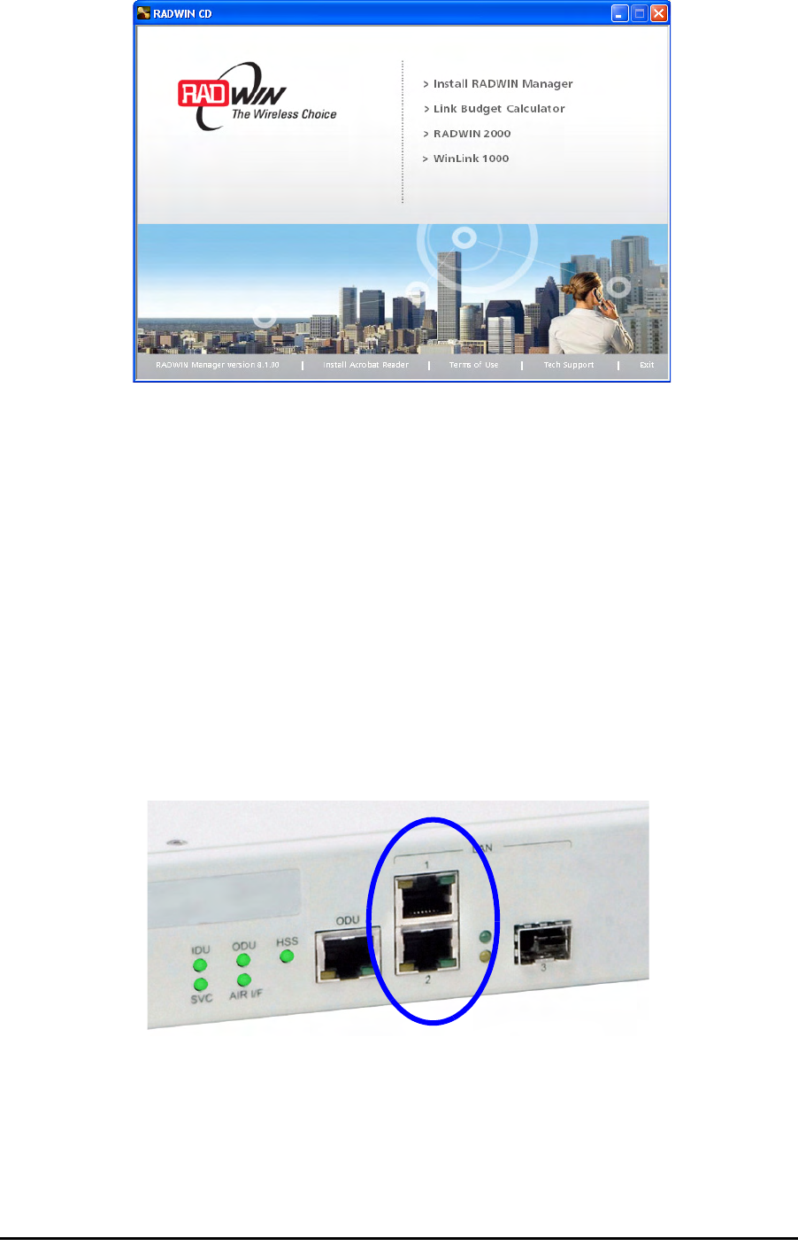
Starting the RADWIN Manager Chapter 4
RADWIN 1000/2000/3000 User ManualVersion 2.5.30p1 4-2
2. Choose Install RADWIN Manager and follow the on-screen instructions
of the installation wizard to complete the setup of the RADWIN Manager
application.
If the installation program fails to start, browse to your CD/DVD drive,
chose the setup.exe program and run it.
Any PC running the RADWIN Manager application can be used to configure
a RADWIN 1000/2000/3000 link.
Starting the RADWIN Manager
¾To start the RADWIN Manager:
1. Connect the managing computer to one of the two LAN ports as shown
in figure 4-1 below:
Figure 4-1: LAN ports on the front panel of the IDU-C
If you are not using a direct connection as above, ensure that you have
IDU to managing computer connectivity (e.g. through a LAN).
2. Check that you have connectivity to the ODU. You can do this by opening
up a command line session (Start|Run and then type, cmd). At the
command prompt, type
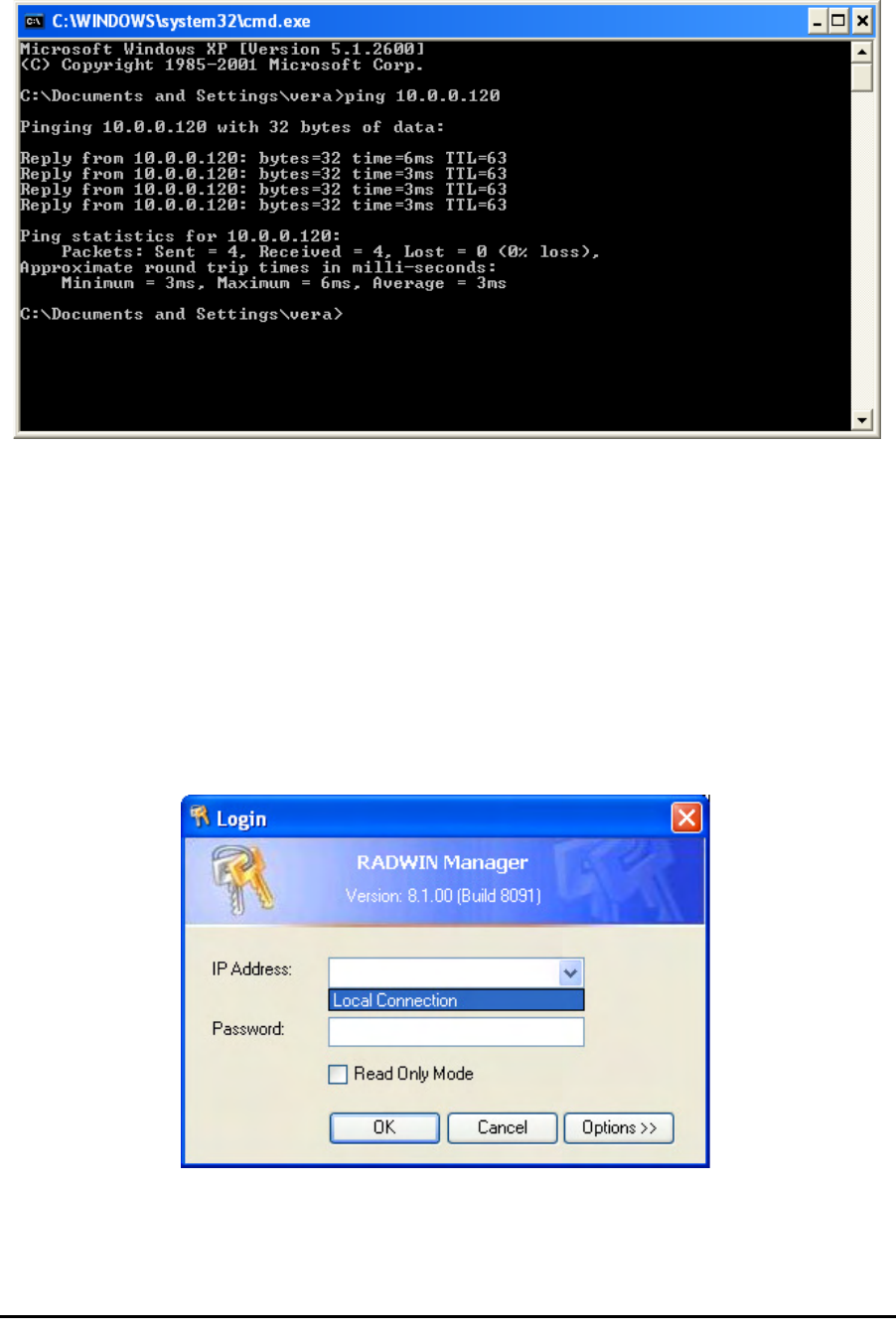
Starting the RADWIN Manager Chapter 4
RADWIN 1000/2000/3000 User ManualVersion 2.5.30p1 4-3
ping 10.0.0.120
You should see something like this:
Figure 4-2: Pinging an uninstalled and unconfigured link
Any other response from ping means that the ODU is not responding.
Check your Ethernet connection and that both the the IDU and ODU are
switched on and then try again. If you do not succeed, seek assistance
from RADWIN Customer Support.
3. Dismiss the command line session.
4. Double-click the RADWIN Manager icon on the desktop, or click
Start|Programs|RADWIN Manager|RADWIN Manager.
The Login dialog box appears.
Figure 4-3: Login Screen
5. Type an IP address for the ODU (if you connect through a network), or
click Local Connection (if you are connected directly to the IDU port).

Starting the RADWIN Manager Chapter 4
RADWIN 1000/2000/3000 User ManualVersion 2.5.30p1 4-4
6. Enter the password
7. If you are a user with Read-Write permission, click Options to enter the
Community options.
Warning
1. If you log in on Local Connection, but your physical connection is
not local (i.e. anything other than a direct connection between
the managing computer and the IDU), then any configuration
you carry out may affect other links in the network.
2. If you log in via an over-the-air IP address, you will receive a
warning. If you reset the site to which you are connected to
factory settings, you can lock yourself out of the Link.
3. Network login (IP address to the ODU) is recommended.
Note
The default IP address for the ODU is 10.0.0.120. The subnet mask is
255.0.0.0.
The actual IP address is defined during link configuration (see Site
Management: IP Address and VLAN on page 6-4).
Note
The default password is
admin
(see Changing the Log On Password on
page 4-7).
Note
RADWIN 1000/2000/3000 is protected with Community passwords. A user
may be defined with read-only permission or with read-write permission
(see page 6-14 for more details).
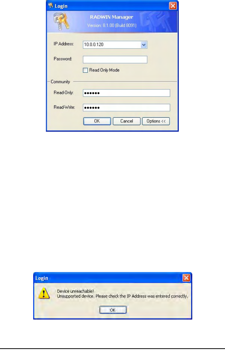
Login Errors Chapter 4
RADWIN 1000/2000/3000 User ManualVersion 2.5.30p1 4-5
Figure 4-4: Login Screen with Community options visible
• If you are using the system for the first time, leave the default Com-
munity passwords,
netman
for read-write, and
public
for read-
only.
• If Community values were previously defined, enter them under
Community in the Read-Only or Read-Write boxes.
• If you are a user with read-only permission, click the Read Only
Mode check box.
The RADWIN Manager main window is displayed (see figure 4-7).
Login Errors
Unsupported Device
Attempting to connect to an unsupported device will result in the following
error message:
Figure 4-5: Unsupported device message
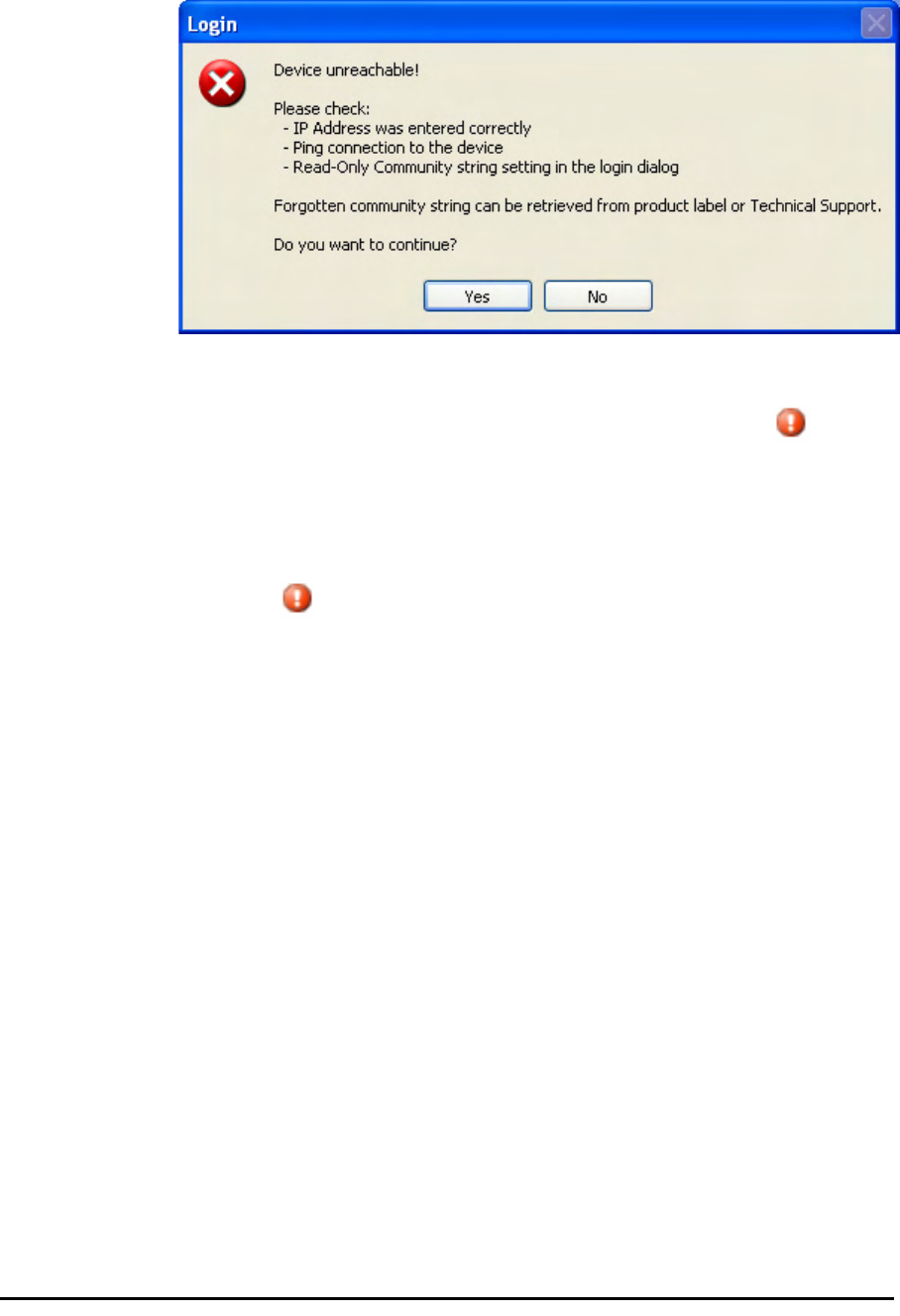
Incorrect IP Address Chapter 4
RADWIN 1000/2000/3000 User ManualVersion 2.5.30p1 4-6
Incorrect IP Address
If the IP address chosen is invalid or the link is unreachable, the following
error message will be displayed:
Figure 4-6: Unreachable device message
In both of the above situations, you will see a warning graphic along-
side the IP Address field.
Incorrect Password
If you type an incorrect password in the Login screen, you will see a warn-
ing graphic alongside the password field.
Continuing without an IP Address
The RADWIN Manager provides limited “offline” functionality when there is
no accessible IDU/ODU. It is primarily for setting managing computer
related parameters and running the Link Budget Calculator. The offline func-
tionality is shown in table 4-2 below. The table does not show menu items
grayed out.

Changing the Log On Password Chapter 4
RADWIN 1000/2000/3000 User ManualVersion 2.5.30p1 4-7
Changing the Log On Password
¾To change the log on password:
1. From the Tools menu, select Change Password.
The Change Password dialog box appears.
2. Enter the current password, and the new password.
3. Click OK to confirm.
Installing the Link: First steps
At this point the main window of the RADWIN Manager should be displayed:
Table 4-2: RADWIN Manager: Offline Functionality
Menu level Function Reference
Top +1 +2
File
Log Off Return to Log On dialog.
Same as Log Off button
Exit Exit the RADWIN Manager.
Same as Exit button
Tools
Change
Password Change the Log On pass-
word dialog page 4-7
Events Log page 7-10
Clear
Events Clear local events log
Save to
File Save events log data to a file
Help
RADWIN
Manager
Help
View online help version of
the User Manual
Link Budget
Calculator Calculator opened in default
browser Appendix D
Get
Diagnostics
Information
Obtain system information page 7-1
About
RADWIN
Manager
RADWIN Manager build
information
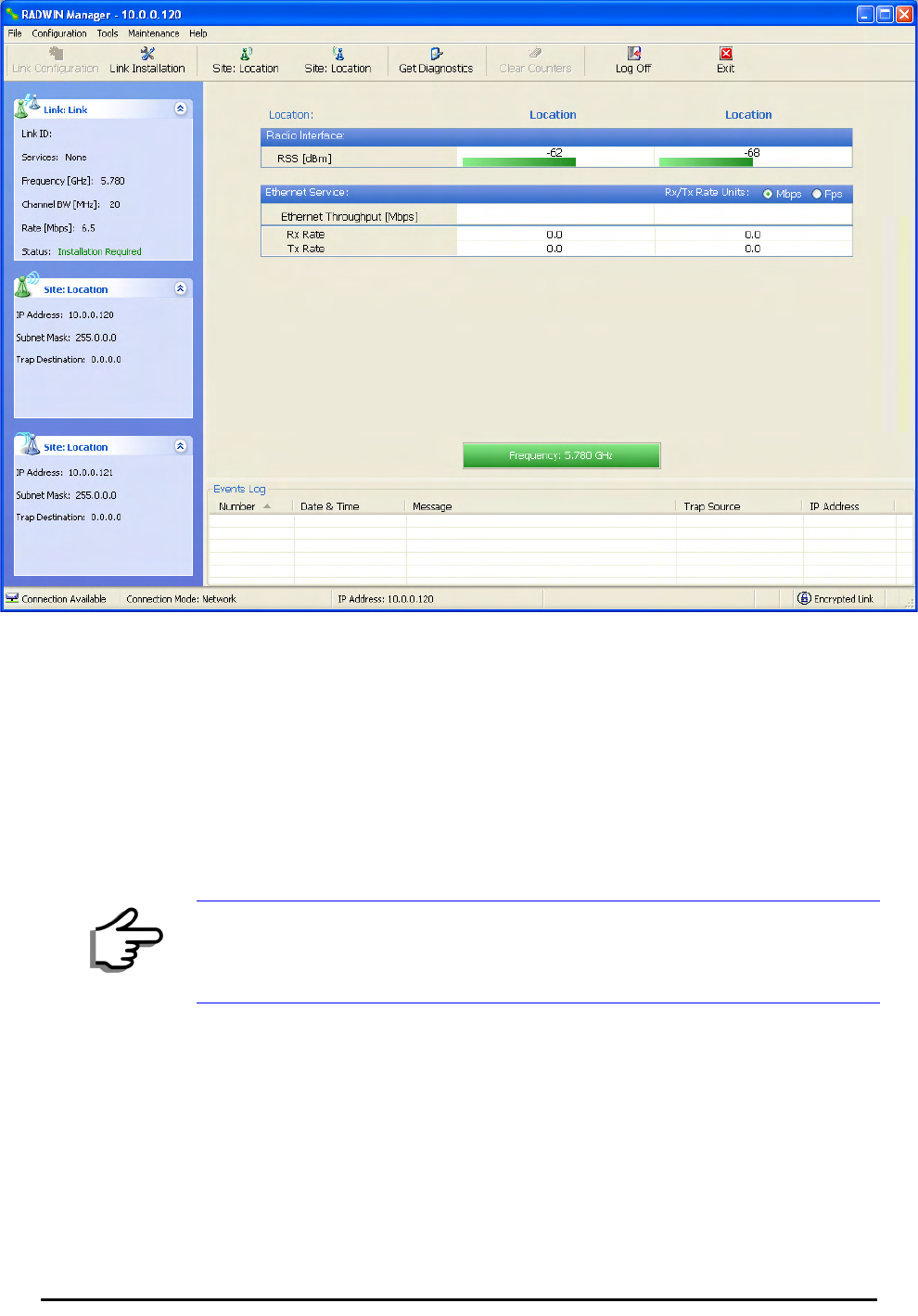
Installing the Link: First steps Chapter 4
RADWIN 1000/2000/3000 User ManualVersion 2.5.30p1 4-8
Figure 4-7: Opening RADWIN Manager window prior to installation
A detailed field by field description of the contents of the RADWIN Manager
main window may be found in chapter 5.
The procedure required to make the link functional has three phases:
1. Link Installation - which we will detail below.
Installation actually gets the link operational by setting the link parame-
ters. It uses a fixed channel at the lowest possible modulation, BPSK at
6.5Mbps and will work under the harsh interference condition.
2. Link Configuration - described in chapter 5.
Configuration provides much the same functionality as Installation, but
for a running link. A fallback to Installation mode is provided for situa-
tions which cannot be handled without resetting the link, such as
antenna realignment and IDU or ODU replacement.
The Link Installation and Configuration phases are both carried out with
Wizards, which “walk you through” the processes. The Wizards are visu-
ally quite similar and will be described in detail below.
Note
During the installation procedure, the definition of all parameters is
automatically applied to both sides of the link.

Default Settings Chapter 4
RADWIN 1000/2000/3000 User ManualVersion 2.5.30p1 4-9
3. Site Configuration - described in chapter 6.
Site specific configuration for each side of the link is available at any time
- under a running link or under the restricted Installation mode.
Site Configuration consists of a set of panels, which may be invoked indi-
vidually in any order, as needed.
Default Settings
The default settings of the RADWIN 1000/2000/3000 configuration parame-
ters are listed in table 4-3 below:
Front Panel LEDs on the IDU-C
The front panel LEDs on the IDU provide basic information about link sta-
tus.
Note
An installed and configured link can be returned to installation mode for re-
installation and configuration from last settings or from factory settings.
• Reversion to installation mode requires a complete break in the link
service
• Configuration mode may vary the service throughput and quality, but
without a service break
Table 4-3: Default Settings
Parameter Default Value
ODU IP Address 10.0.0.120
Subnet Mask 255.0.0.0
Trap destination 0.0.0.0
Manager Login password admin
Link ID Link
Site 1 Site
Site 2 Site
Link Password wireless-bridge
Rate Adaptive
Ethernet Configuration Auto Detect
Radio Link Failure Actions No action
Bridge or Hub mode Hub Mode, Aging time = 300 sec
Community values Read-write – netman
Read-only – public

Installation Menu and Toolbar Functionality Chapter 4
RADWIN 1000/2000/3000 User ManualVersion 2.5.30p1 4-10
Figure 4-8: IDU-C Front Panel LEDs
The following table describes the indicators:
Installation Menu and Toolbar Functionality
The RADWIN Manager menu functionality is displayed in table 4-5. The
Toolbar buttons are detailed in table 4-6.
Table 4-4: Front Panel LEDs
Name Color Function
IDU
With Ethernet only
Green
Green
Red
During power-up only
IDU operational
Failure
ODU Green
Red
ODU-to-IDU communication link is operating
ODU-to-IDU communication link is disrupted
AIR I/F Green
Orange
Red
Wireless link is synchronized
During installation mode only
Wireless link lost synchronization
SVC Off
HSS Off

Installation Menu and Toolbar Functionality Chapter 4
RADWIN 1000/2000/3000 User ManualVersion 2.5.30p1 4-11
Table 4-5: RADWIN Manager main menu functionality
Menu level Function Reference
Top +1 +2
File
Log Off Return to Log On dialog.
Same as Log Off button
Exit Exit the RADWIN Manager.
Same as Exit button
Configuration
Link
Configuration
Run the Configuration Wiz-
ard. Not available in
installation mode
1 Configure
<Site 1 name>
Provides limited configura-
tion for site. Has a path to
return to installation
mode
2 Configure
<Site 2 name>
Provides limited configura-
tion for site. Has a path to
return to installation
mode
Link Installation Runs the Installation Wiz-
ard. Not available in
configuration mode
Tools
Performance
Monitoring
Report
Active Alarms
1 <Site 1 name> Shows active alarms for
<Site 1 name>
2 <Site 2 name> Shows active alarms for
<Site 1 name>
Change
Password Change the Log On pass-
word dialog page 4-7
Events Log
page 7-10
Clear Events Clear local events log
Save to File Save events log file
Preferences Local preferences dialog

Installation Menu and Toolbar Functionality Chapter 4
RADWIN 1000/2000/3000 User ManualVersion 2.5.30p1 4-12
Maintenance
Clear counters Disabled
Loopbacks Disabled
Reset 1 <Site 1 name> Reset <Site 1 name> ODU
2 <Site 2 name> Reset <Site 2 name> ODU
Help
RADWIN
Manager Help View online version of the
User Manual
Link Budget
Calculator Calculator opened in
default browser Appendix D
Get Diagnostics
Information Obtain system information page 7-1
About RADWIN
Manager Manager build and system
information
Table 4-6: RADWIN Manager Toolbar
Item Description
Link Configuration Changes configuration parameters of an operating wireless link;
assigns text files for storing alarms, statistics and configuration
data. This button is disabled until a link installation has
been completed
Link Installation Performs preliminary configuration of the system. This button is
disabled after the link is installed
Site: <Site 1 name> Opens the Site configuration dialog for Site A. Same as
Configuration | 1 Configure <Site 1 name>
Site: <Site 2 name> Opens the Site configuration dialog for Site B. Same as
Configuration | 2 Configure <Site 2 name>
Get Diagnostics Obtain system information
Clear Counters Disabled
Log off Closes the current session and logs off RADWIN Manager
Exit Exits RADWIN Manager
Table 4-5: RADWIN Manager main menu functionality (Continued)
Menu level Function Reference
Top +1 +2
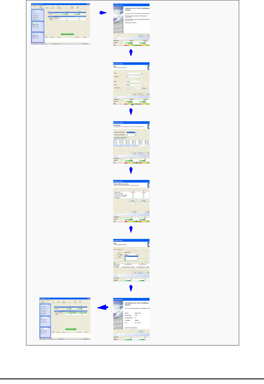
Installing the Link: Overview Chapter 4
RADWIN 1000/2000/3000 User ManualVersion 2.5.30p1 4-13
Installing the Link: Overview
The Installation wizard has seven steps as shown in table 4-7 below.
Table 4-7: Link Installation Wizard
1Wizard welcome
2System parameters
•Link ID
• Site details
3Channel settings - ACS
Configuration
4Tx power and antenna
settings
5Services - Adaptive or
fixed
6Wizard summary and
completion
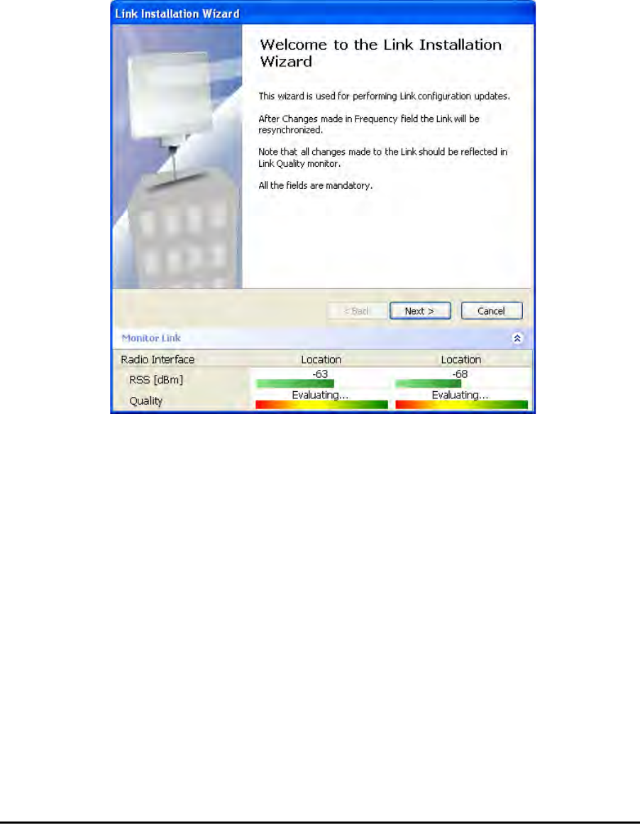
Installing the Link: Step 1, Start the Wizard Chapter 4
RADWIN 1000/2000/3000 User ManualVersion 2.5.30p1 4-14
Installing the Link: Step 1, Start the Wizard
In the tool bar of the RADWIN Manager main window, click the Link
Installation button. The Link Installation button is only accessible if anten-
nas are properly aligned. If this box is “grayed out”, you should align the
antennas as set out in Connecting and Aligning ODUs / Antennas on
page 3-13.
The Installation Wizard opens:
Figure 4-9: Link Installation Wizard
The bottom data area reproduces the corresponding data from the main
window - which the above panel obscures. See page 5-7 for a field by field
description of this data area.
Click Next to proceed with the installation procedure.
Installing the Link: Step 2, System Parameters
The system dialog box opens:
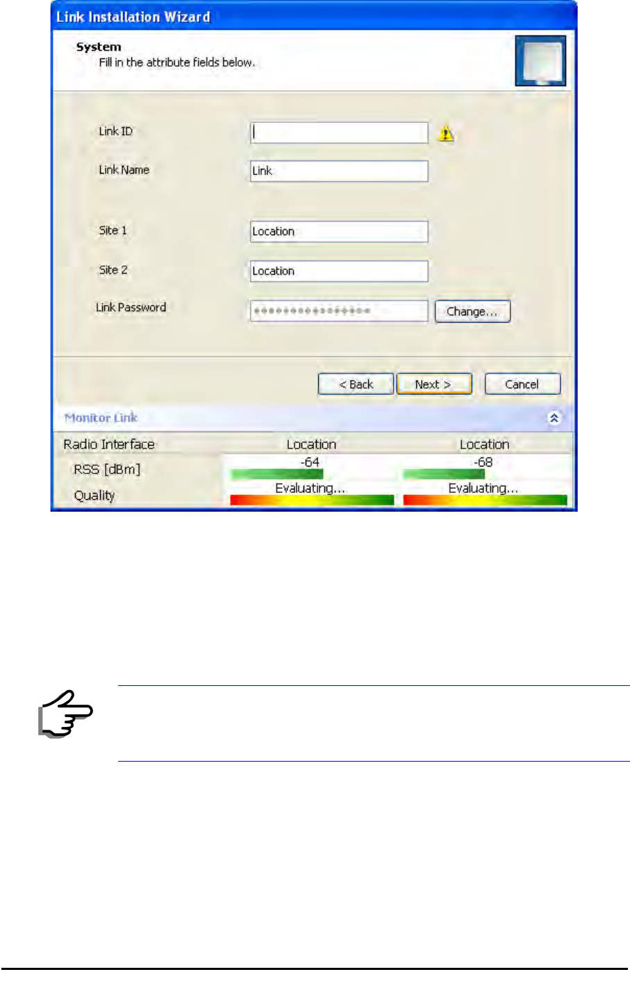
Installing the Link: Step 2, System Parameters Chapter 4
RADWIN 1000/2000/3000 User ManualVersion 2.5.30p1 4-15
Figure 4-10: : Installation Wizard, System dialog box
¾To complete Installation Step 2:
1. Enter a Link ID. (Link ID - must be unique for each link in the area). The
Link ID must include at least eight alphanumeric characters. Up to 24
characters are allowed.You should use a Link ID composed of both
alphabetic and numeric characters.
2. Enter a Link Name for the link identification. The default name is “Link”.
You should change it.
3. Enter names for Site 1 and Site 2. The default names are both “Loca-
tion”. You should change them. Throughout this manual, we use A for
Site 1 and B for Site 2.
Note
Both sides of a link must have the same Link ID.
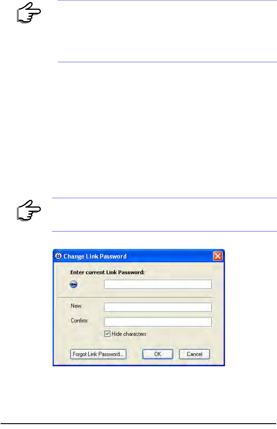
Changing the Link Password Chapter 4
RADWIN 1000/2000/3000 User ManualVersion 2.5.30p1 4-16
4. Optionally enter a new Link Password.
5. Click Next.
The default link with a rate of 6.5 Mbps is evaluated.
The Channel Setting dialog box appears. Proceed to Installing the
Link: Step 3, Channel Settings, below.
Changing the Link Password
The default password is
wireless-bridge
. Optionally, you can change the
link password as explained here.
¾To change the link password:
1. Click the Change button in the System dialog box.
The Change Link Password dialog box opens.
Figure 4-11: Change Link Password dialog box
2. Enter the current link password (The default link password for a new
ODU is wireless-bridge).
Note
If the Link Password is incorrect a link is established but configuration
cannot be performed and no services are available. A new link password
may be obtained from RADWIN Customer Support or use the alternative
password supplied with the product. (see for more details).
The link password is peculiar to the link itself and should not be confused
with the RADWIN Managerlog on password.
Note
Use the Hide characters check box for maximum security

Installing the Link: Step 3, Channel Settings Chapter 4
RADWIN 1000/2000/3000 User ManualVersion 2.5.30p1 4-17
If you have forgotten the Link Password, click the Forgotten Link Pass-
word button. The following window is displayed:
Figure 4-12: Lost or forgotten Link Password recovery
Follow the instructions to use the Alternative Link Password, and click OK
to finish. You are returned to the window in figure 4-11 above. Con-
tinue with the next step.
3. Enter a new password.
4. Retype the new password in the Confirm field.
5. Click OK.
6. Click Yes when asked if you want to change the link password.
7. Click OK at the Password changed success message.
Installing the Link: Step 3, Channel Settings
RADWIN 1000/2000/3000 systems have a feature called Automatic Channel
Selection (ACS). In the event of sync loss, ACS chooses the first available
channel in a list of monitored channels nominated in the Channel settings
window of figure 4-13 below. A channel switch takes place sufficiently fast
as to ensure no loss of service.
Note
• Restoring Factory Defaults returns the Link Password to
wireless-
bridge
.
• If the link is inactive, then the link password may also be changed
from the Site Configuration dialogs. See page 6-14.
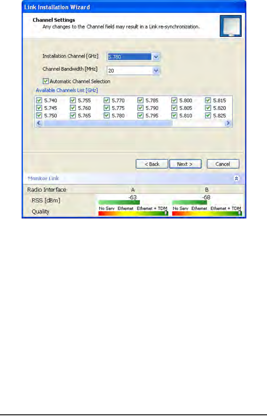
Installing the Link: Step 3, Channel Settings Chapter 4
RADWIN 1000/2000/3000 User ManualVersion 2.5.30p1 4-18
Figure 4-13: Channel Settings - Automatic Channel Selection
The default frequency for the product is shown.
¾To select channels to be used by the link:
1. Select the main frequency from the Installation Channel box.
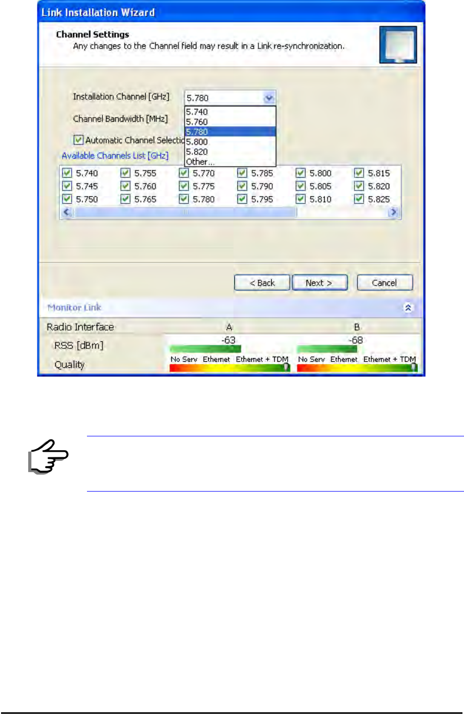
Installing the Link: Step 4, Tx Power and Antenna Settings Chapter 4
RADWIN 1000/2000/3000 User ManualVersion 2.5.30p1 4-19
Figure 4-14: Channel Settings - Showing available installation rates
2. Click the check box if Automatic Channel Selection is required.
3. The Available Channels List contains all of the allowable channels for the
link. Check the channels that can be automatically selected.
Selecting a new channel causes the system quality to change. The Qual-
ity bar provides an indication of the link quality from poor (red) to good
(green) as shown in the bottom of figure 4-13 above.
4. Click Next.
Installing the Link: Step 4, Tx Power and Antenna Settings
The Tx Power and Antenna Parameters dialog appears.
Note
For version 2.1, channel bandwidth is set to 20 MHz and cannot be changed.
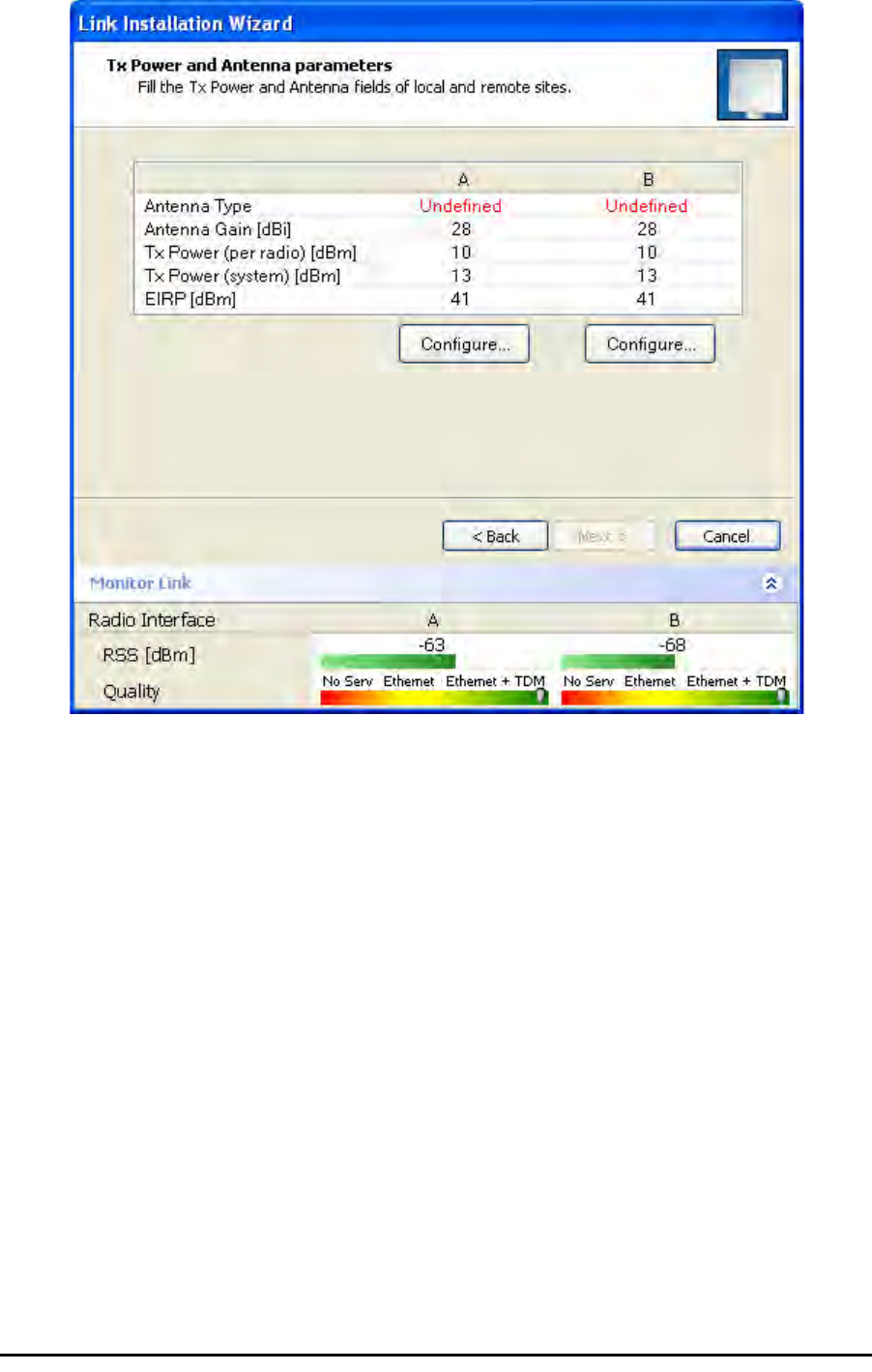
General Chapter 4
RADWIN 1000/2000/3000 User ManualVersion 2.5.30p1 4-20
.
Figure 4-15: Transmission Power and Antenna Parameters
The choice of Tx power, antenna gain and cable loss determines the EIRP
and is affected by such considerations as radio limitations and regulatory
restrictions.
Before proceeding to antenna installation details, the following background
information should be considered:
General
Each RADWIN 1000/2000/3000 ODU is made of two radio transceivers
(radios). The radios make use of algorithms that utilize both polarization
and space diversity resulting in enhanced capacity, range and link availabil-
ity. The number of antennas (i.e. radios) used is determined by user config-
uration and by automatic system decisions, explained below.
Dual Antennas at Both Sites
Using dual antennas at both sites (single bipolar antenna or two monopolar
antennas) enables the use of MIMO technology. With MIMO the system
doubles the link capacity. At the same time, it keeps the same rate and
modulation per radio as was used with single antenna, thus increasing
capacity, range and availability.

Single Antennas at Both Sites Chapter 4
RADWIN 1000/2000/3000 User ManualVersion 2.5.30p1 4-21
For example with a dual antenna RADWIN 1000/2000/3000 can transmit at
modulation of 64QAM and FEC of 0.83 and get an air rate of 130 Mbps,
compared to 65 Mbps with single antenna.
To work in this mode, each antenna port must be connected to an antenna,
the RSS level in both receivers should be balanced and a minimal separation
between the antennas must be maintained. (For example, by using dual
polarization antennas a cross polarization separation is attained).
Upon selecting Antenna Type as Dual, RADWIN 1000/2000/3000 automati-
cally doubles the air rates.
RADWIN Manager indicates a case of unbalanced RSS between the two
antennas.
Single Antennas at Both Sites
By selecting a single antenna at both sites the ODUs operate with a single
radio that is connected to the ANT 1 connector. The second radio is auto-
matically shut down.
Single and Dual Antennas
In this mode one of the sites uses the ODU with a single antenna while the
other site uses the ODU with a dual antenna.
The advantages in this mode in comparison to using a single antenna in
both sites are doubled total Tx power and additional polarization and/or
space diversity.
RADWIN 1000/2000/3000 automatically switches to this mode if one of the
ODUs is connected to a dual antenna or if the RSS at one of the ODU receiv-
ers is below minimal level.
The air rates used in this mode are same as when using single antennas in
both sites.

Considerations for Changing Antenna Parameters Chapter 4
RADWIN 1000/2000/3000 User ManualVersion 2.5.30p1 4-22
The rates used by RADWIN 1000/2000/3000 are shown in Table 4-5 below:
Considerations for Changing Antenna Parameters
Let:
maxAllowedTx Power denote the maximum Tx Power practically avail-
able from an ODU. It appears as Tx Power per Radio in
figure 4-16 below.
maxRegEIRP denote the maximum EIRP available by regulation. It will be
determined by three factors:
• per band/regulation
• per channel bandwidth
•antenna gain
It appears in figure 4-16 as Max EIRP.
maxRegTxPower denote the maximum regulatory Tx Power for the
equipment, also having regard the above three points
Table 4-8: RADWIN 1000/2000/3000 Transmission rates
Radio Modulation FEC Air-Rate
[Mbps]
Single BPSK 1/2 6.5
Single QPSK 1/2 13
Single QPSK 3/4 19.5
Single 16QAM 1/2 26
Single 16QAM 3/4 39
Single 64QAM 2/3 52
Single 64QAM 3/4 58.5
Single 64QAM 5/6 65
Dual BPSK 1/2 13
Dual QPSK 1/2 26
Dual QPSK 3/4 39
Dual 16QAM 1/2 52
Dual 16QAM 3/4 78
Dual 64QAM 2/3 104
Dual 64QAM 3/4 117
Dual 64QAM 5/6 130
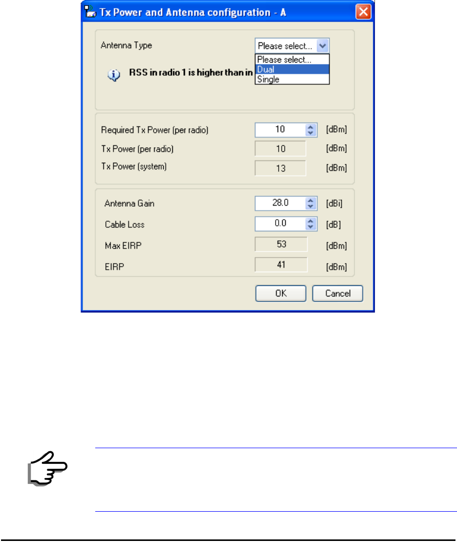
Considerations for Changing Antenna Parameters Chapter 4
RADWIN 1000/2000/3000 User ManualVersion 2.5.30p1 4-23
maxODUTxPower denote the maximum Tx Power of the ODU, itself
depending on the air rate used.
Then, the following relationship must be satisfied: ... (*)
These parameters are controlled as follows:
¾To set Tx power and configure antennas:
1. Click the Configure buttons in turn to configure the antennas on both
sides of the link. Each one offers a dialog like this:
Figure 4-16: Antenna configuration dialog with opened type selection
2. Choose the antenna type and required transmission (Tx) power for the
first site and click OK. Repeat the process for the second site.
The Tx power (per radio) indicates the power of each radio inside the
ODU and is used for Link Budget Calculations. The Tx power (System)
shows the total transmission power of the ODU and is used to calculate
the EIRP according to regulations.
Note
To see the relationship between Tx Power (radio) and TX Power (system),
note that so that if you double the power in
milliWatts (for two radios) then dBm will increase by .
maxAllowedTxPower min maxRegEIRP
AntennaGain CableLoss maxRegTxPower,+– ()
≤
dBm 10 milliWatt
10
log×=
10 2 3≈
10
log×
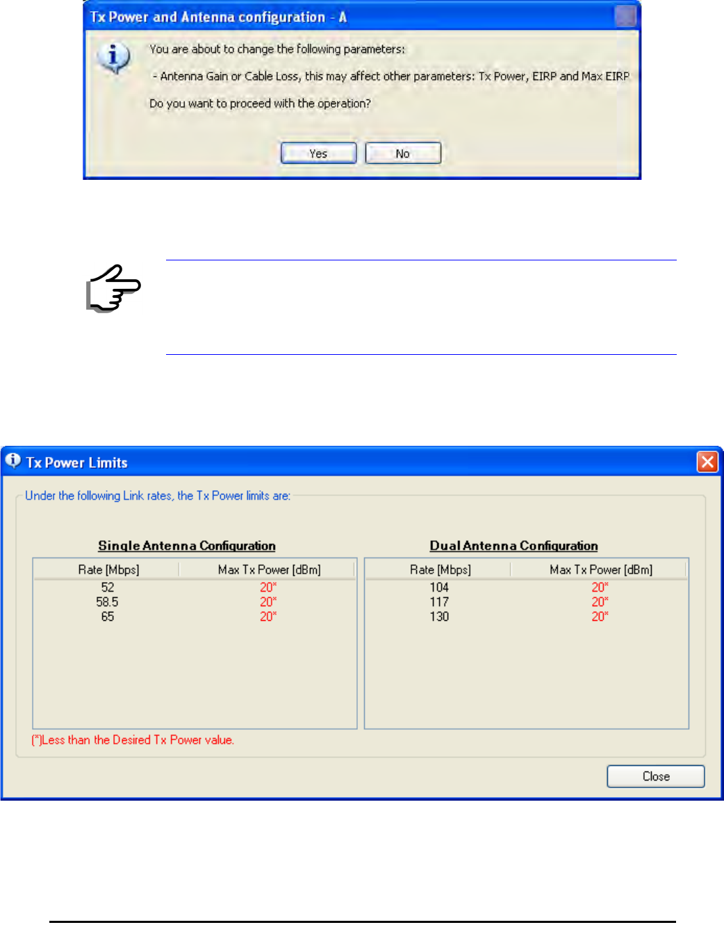
Considerations for Changing Antenna Parameters Chapter 4
RADWIN 1000/2000/3000 User ManualVersion 2.5.30p1 4-24
3. Set the Antenna Gain and Cable Loss. If do this you will receive a warn-
ing message:
Figure 4-17: Antenna parameters change warning
If inequality (*) above is violated, then the following warning window is
displayed:
Figure 4-18: Tx Power Limits
The precise relationship between the items in inequality (*) and the win-
dow of figure 4-16 is follows:
Note
• The Max EIRP level will be automatically set according to the selected
band and regulation.
• The EIRP level is the sum of the System Tx power and the Antenna
Gain minus the Cable Loss.
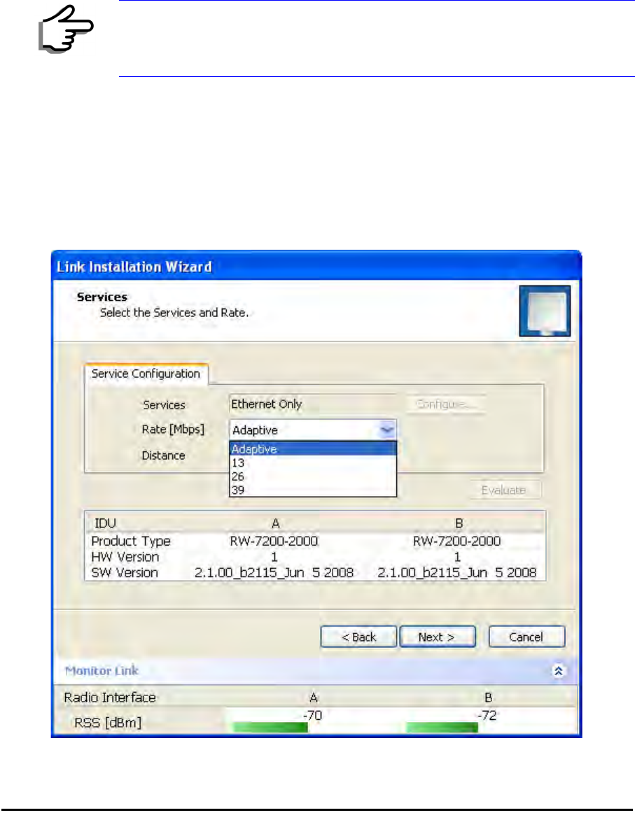
Installing the Link: Step 5, Services Chapter 4
RADWIN 1000/2000/3000 User ManualVersion 2.5.30p1 4-25
• Required Tx Power (per radio) will be adjusted down to the
lesser of the value entered and maxAllowedTxPower
•TxPower (system)is maxAllowedTxPower + 3 (for 2 radios)
•Max EIRP is maxRegEIRP.
•EIRP is maxAllowedTx Power + Antenna Gain - Cable
Loss
The table in figure 4-18 only shows rates where the maximum Tx
Power is the limitation, rather than regulations.
When you close the window of figure 4-18, the change you requested
will not be honored, and you will need to try again.
4. When you are finished with Tx Power configuration, Click Next.
Installing the Link: Step 5, Services
The Services dialog appears:
Figure 4-19: Services and Rates dialog
Note
Recall that maxAllowedPower and maxEIRP are regulatory. In an
unregulated environment, the only limit is maxODUTxPower.
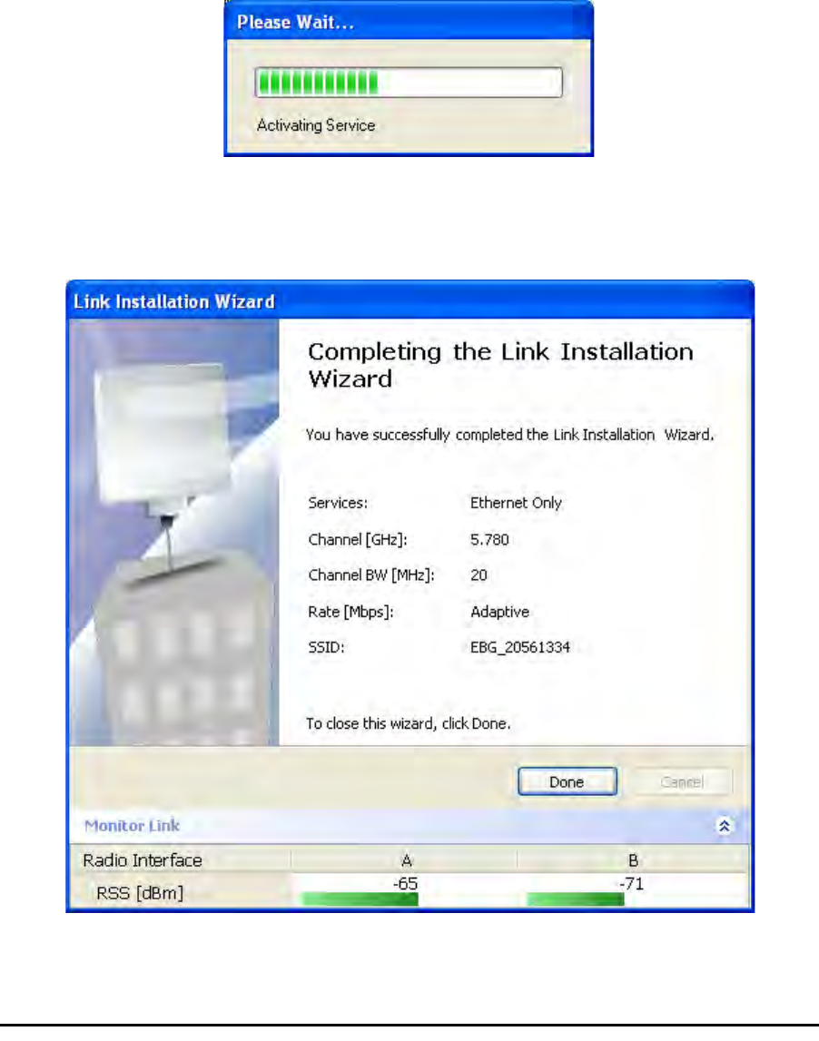
Installing the Link: Step 6, Installation Summary and Exit Chapter 4
RADWIN 1000/2000/3000 User ManualVersion 2.5.30p1 4-26
For version 2.1, Ethernet Only is the only available service. You may choose
a specific modulation rate or use Adaptive.
¾To choose a modulation rate:
1.Choose Adaptive or one of the available rate (see page 1-4 for informa-
tion about Automatic Adaptive Rate).
2. Click Next to continue.
The service is activated as show below:
Installing the Link: Step 6, Installation Summary and Exit
Figure 4-20: Installation Wizard Exit Summary
Click Done to return to the main window.
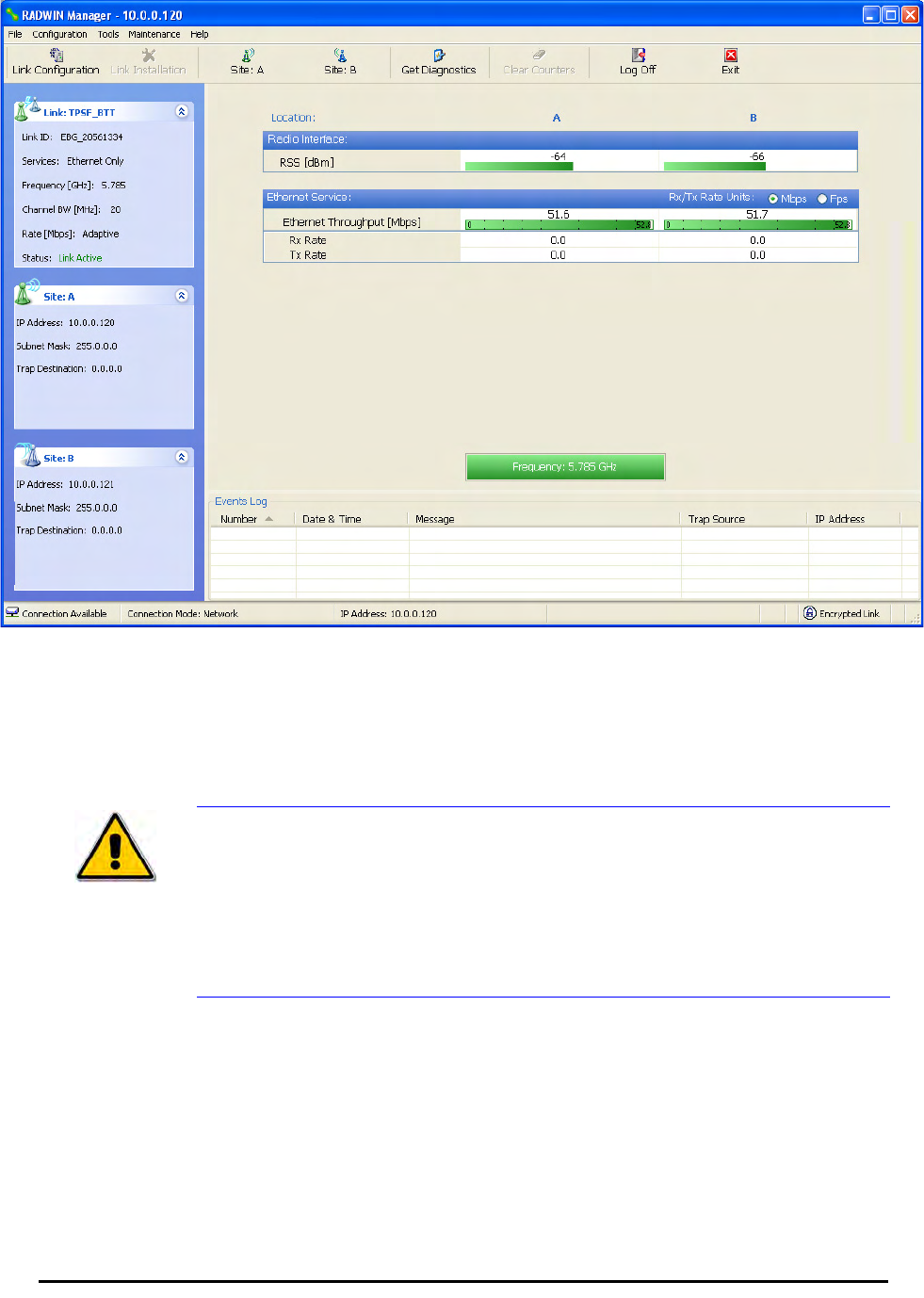
Installing the Link: Step 6, Installation Summary and Exit Chapter 4
RADWIN 1000/2000/3000 User ManualVersion 2.5.30p1 4-27
The main window now reflects the installation:
Figure 4-21: Main window of the manager after installation
¾To verify the installation:
• Verify that the Radio Signal Strength (RSS) is according to expected
results as determined by the Link Budget Calculator.
Caution
Installation mode, as described above, may be re-entered using
Configuration | 1 Configure Site A and Installation Mode the Site
Configuration dialog. Some Installation mode functionality may cause a
break in link service.
If you can accomplish link changes without breaking the service, always
prefer to use Configuration mode, described in chapter 5.

RADWIN 1000/2000/3000 User ManualVersion 2.5.30p1 5-1
Chapter 5
Configuring the Link
This chapter describes the link configuration procedure, which is performed
after the installation of both sides of the RADWIN 1000/2000/3000 link, as
set out in chapters 3 and 4.
Link configuration uses a Link Configuration Wizard to redefine the configu-
ration parameters and fine-tune an operational link. Both sides of the link
are configured simultaneously.
The following parameters are configured using the Link Configuration Wiz-
ard:
• System parameters
• Channel settings
• Transmission power and antenna settings
•Service parameters
Link Configuration: Getting Started
The Main Window of the RADWIN Manager
Ensure that the RADWIN Manager is running.
The main window should look similar to that in figure 5-1:
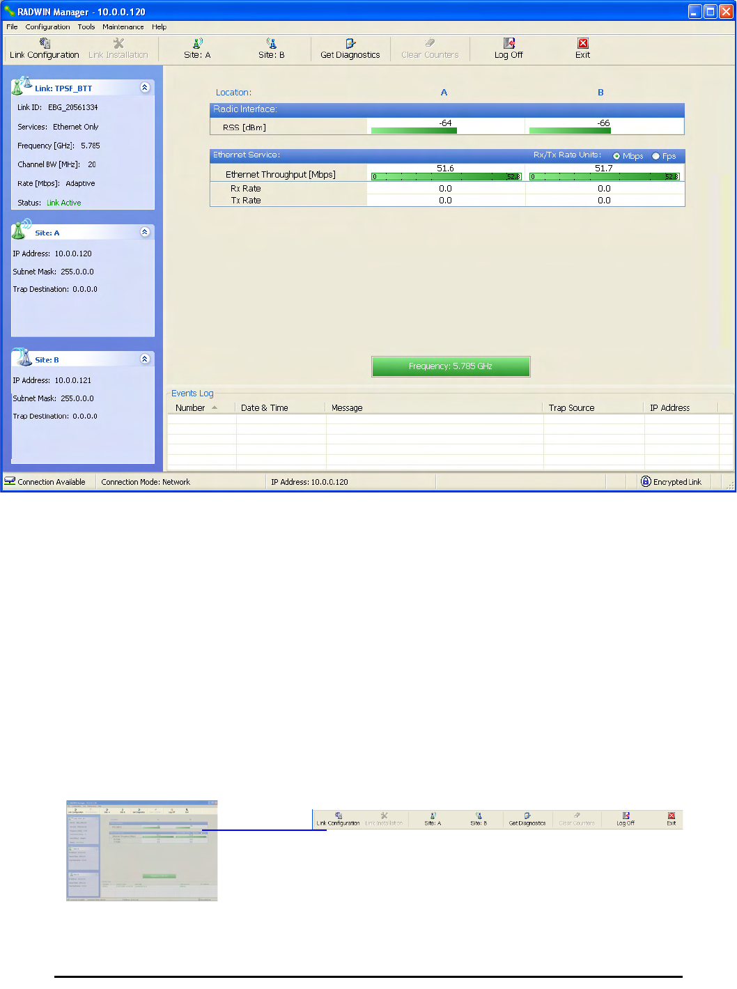
The RADWIN Manager Toolbar Chapter 5
RADWIN 1000/2000/3000 User ManualVersion 2.5.30p1 5-2
.
Figure 5-1: Main window, Wireless Link is Active
Before starting a configuration session, make sure that a communication
link exists between the two sides of the link.
The Link Status indication bar must be green. In the Link Status panel, the
Status field should show Link Active in green.
The main window of the RADWIN Manager contains a large amount of
information about the link. Before proceeding to details of link configuration
we set out the meaning of each item in the main window.
The RADWIN Manager Toolbar
In configuration mode, the RADWIN Manager toolbar contains the following
buttons:
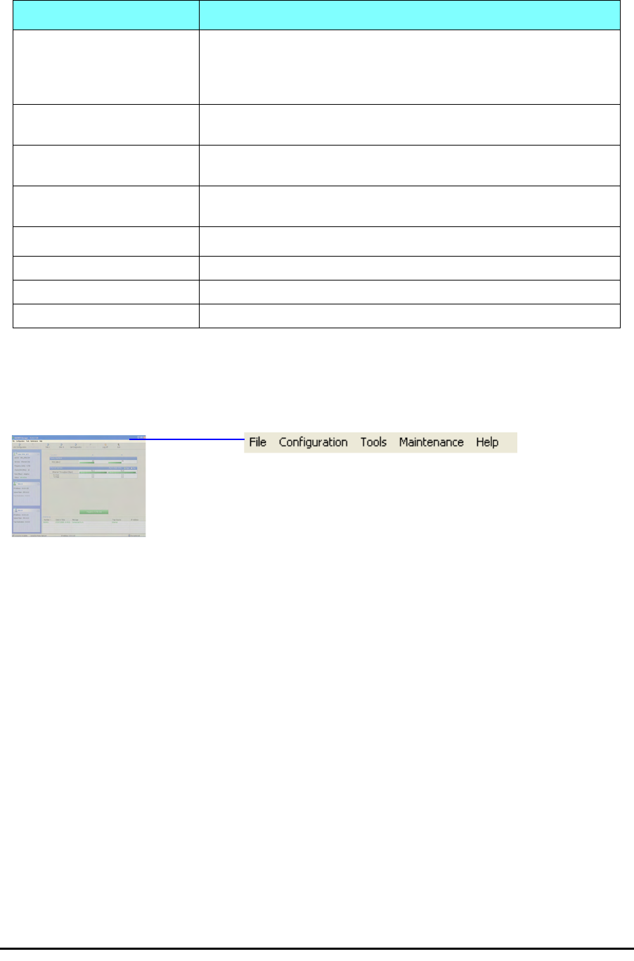
The RADWIN Manager Main Menu Chapter 5
RADWIN 1000/2000/3000 User ManualVersion 2.5.30p1 5-3
The RADWIN Manager Main Menu
The RADWIN Manager menu, is shown in table 5-2 below:
Table 5-1: RADWIN Manager Toolbar
Item Description
Link Configuration Changes configuration parameters of an operating wireless link;
assigns text files for storing alarms, statistics and configuration
data. This button is disabled until a link installation has
been completed
Link Installation Performs preliminary configuration of the system. This button is
disabled after the link is installed
Site: <Site 1 name> Opens the Site configuration dialog for Site A. Same as
Configuration | 1 Configure <Site 1 name>
Site: <Site 2 name> Opens the Site configuration dialog for Site B. Same as
Configuration | 2 Configure <Site 2 name>
Get Diagnostics Obtain system information
Clear Counters Disabled
Log off Closes the current session and logs off RADWIN Manager
Exit Exits RADWIN Manager

The RADWIN Manager Main Menu Chapter 5
RADWIN 1000/2000/3000 User ManualVersion 2.5.30p1 5-4
Table 5-2: RADWIN Manager main menu functionality
Menu level Function Reference
Top +1 +2
File
Log Off Return to Log On dialog.
Same as Log Off button
Exit Exit the manager. Same as
Exit button
Configuration
Link
Configuration Run the Configuration Wiz-
ard. Not available in
installation mode
1 Configure
<Site 1 name> Provides limited configura-
tion for site. Has a path to
return to installation
mode
2 Configure
<Site 2 name> Provides limited configura-
tion for site. Has a path to
return to installation
mode
Installation Runs the Installation Wiz-
ard. Not available in
configuration mode
Tools
Performance
Monitoring
Report
Active Alarms
1 <Site 1 name> Shows active alarms for
<Site 1 name>
2 <Site 2 name> Shows active alarms for
<Site 1 name>
Change
Password Change the Log On pass-
word dialog page 4-7
Events Log page 7-10
Clear Events Clear local events log
Save to File Save events log file
Preferences Local preferences dialog

The RADWIN Manager Main Menu Chapter 5
RADWIN 1000/2000/3000 User ManualVersion 2.5.30p1 5-5
Maintenance
Clear counters Disabled
Loopbacks Disabled
Reset
1 <Site 1 name> Reset <Site 1 name> ODU
2 <Site 2 name> Reset <Site 2 name> ODU
Help
RADWIN
Manager Help View online version of the
User Manual
Link Budget
Calculator Calculator opened in
default browser Appendix D
Get Diagnostics
Information Obtain system information page 7-1
About RADWIN
Manager Manager build and system
information
Table 5-2: RADWIN Manager main menu functionality (Continued)
Menu level Function Reference
Top +1 +2
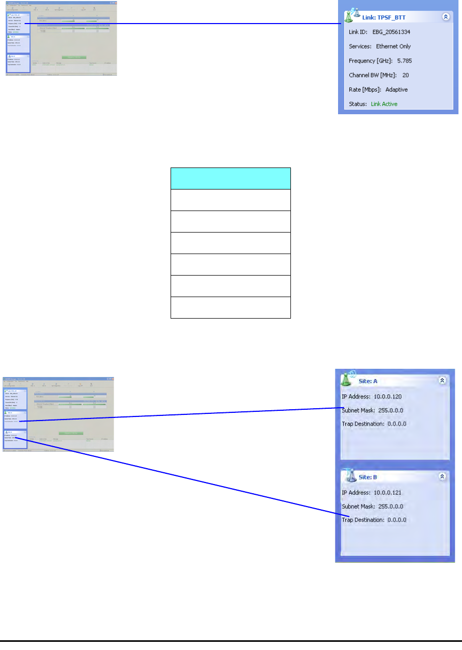
Elements of the RADWIN Manager Main Window Chapter 5
RADWIN 1000/2000/3000 User ManualVersion 2.5.30p1 5-6
Elements of the RADWIN Manager Main Window
Link details pane
The Link details pane on the left is split into three sections. The top section
summarizes information about the link:
The two lower panels show basic link site details:
Table 5-3: Link Details
Item
Link ID
Services selected
Frequency
Channel bandwidth
Rate
Link status
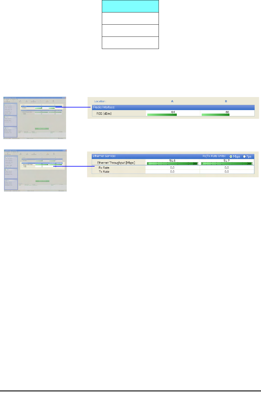
Elements of the RADWIN Manager Main Window Chapter 5
RADWIN 1000/2000/3000 User ManualVersion 2.5.30p1 5-7
Monitor pane
he monitor pane, is the main source of real time information about link per-
formance at both link sites. It includes the following panes (top to bottom):
• Radio Interface, Received Signal Strength (RSS) in dBm
• Ethernet Service:
• Ethernet Throughput: The numbers are the current calculated
throughputs at each site. The colored bars (with numbers) indi-
cate the maximum possible throughput having regard for air
conditions.
• Rx and Tx Rates: Actual Ethernet traffic received and transmit-
ted rates per site, in Mbps of Fbps.
Table 5-4: Link site details, Site A and Site B
Item
IP Address
Subnet Mask
Trap Desalination
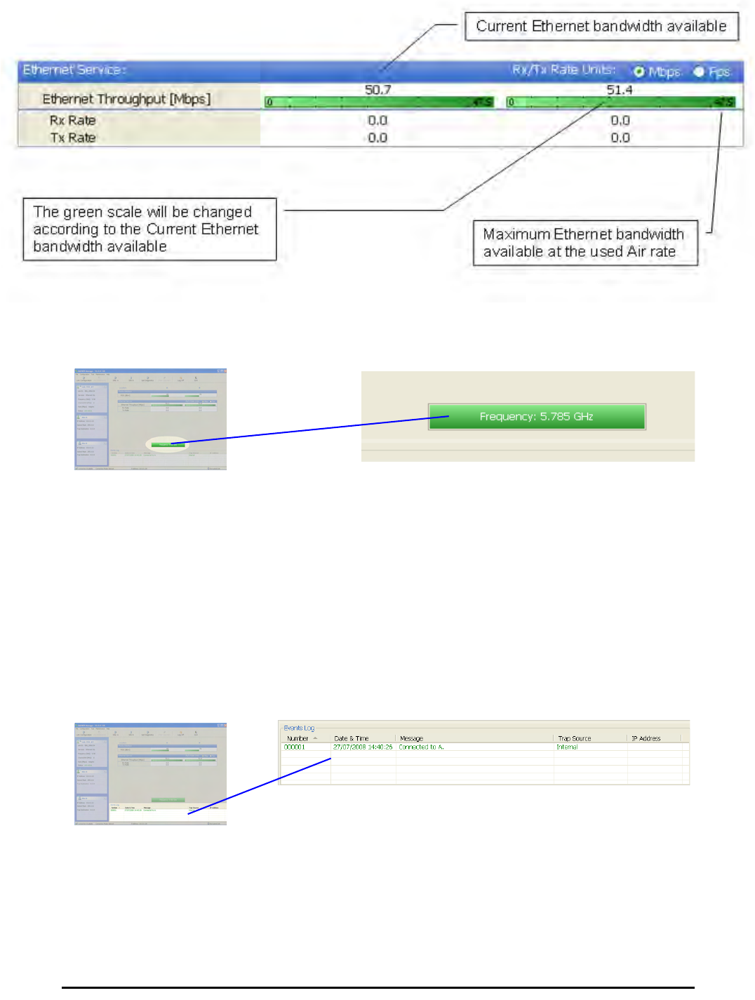
Elements of the RADWIN Manager Main Window Chapter 5
RADWIN 1000/2000/3000 User ManualVersion 2.5.30p1 5-8
Figure 5-2: Ethernet Bandwidth Indication
• Frequency box: It shows the link frequency. The color of the box
indicates the status
•Green is an active link
•Red is an inactive link
•Magenta shows an authentication or compatibility problem
•Brown shows severe compatibility problem
Events Log
The Events Log, stores alarms generated from both sides of the link and is
detailed in chapter 7, The Events Log.
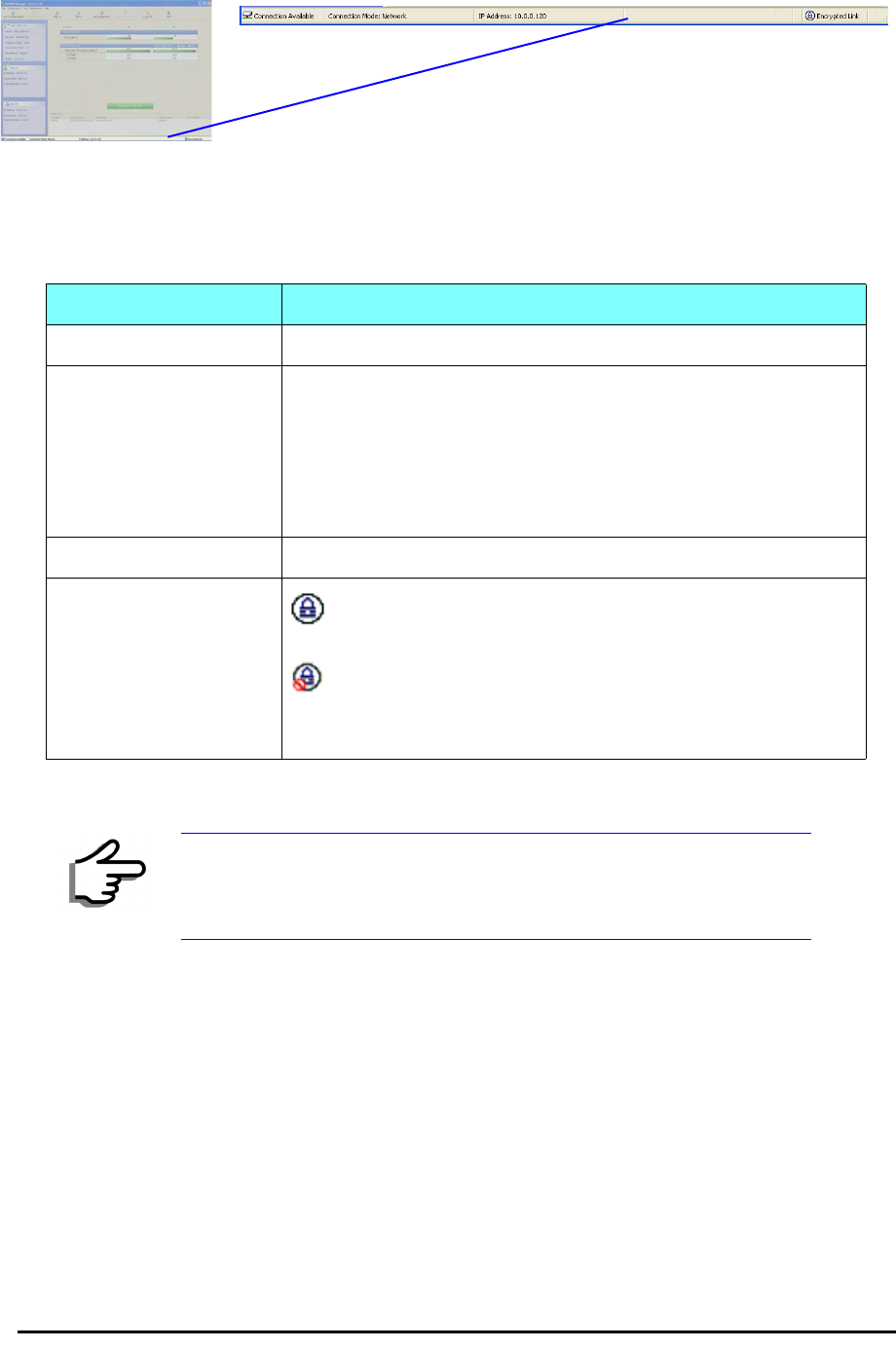
Elements of the RADWIN Manager Main Window Chapter 5
RADWIN 1000/2000/3000 User ManualVersion 2.5.30p1 5-9
Status Bar
The Status bar, displays the following icons:
Table 5-5: Status bar indicators
Icon or Label Purpose
Connectivity Shows if RADWIN Manager is communicating with the ODU.
Connection available
Connection mode to the ODU
• Over-the-Air connection - using the IP address of the
remote unit.
• Local connection - direct connection to the IDU without
using an IP address.
• Network connection - through a LAN
IP Address Login IP address
Encryption indicator
Normally encrypted link
Link password validation failed. The link is encrypted with
default keys. Service and configuration are unavailable. Change
the link password.
Note
There are several “floating” icons, which appear under specific
conditions
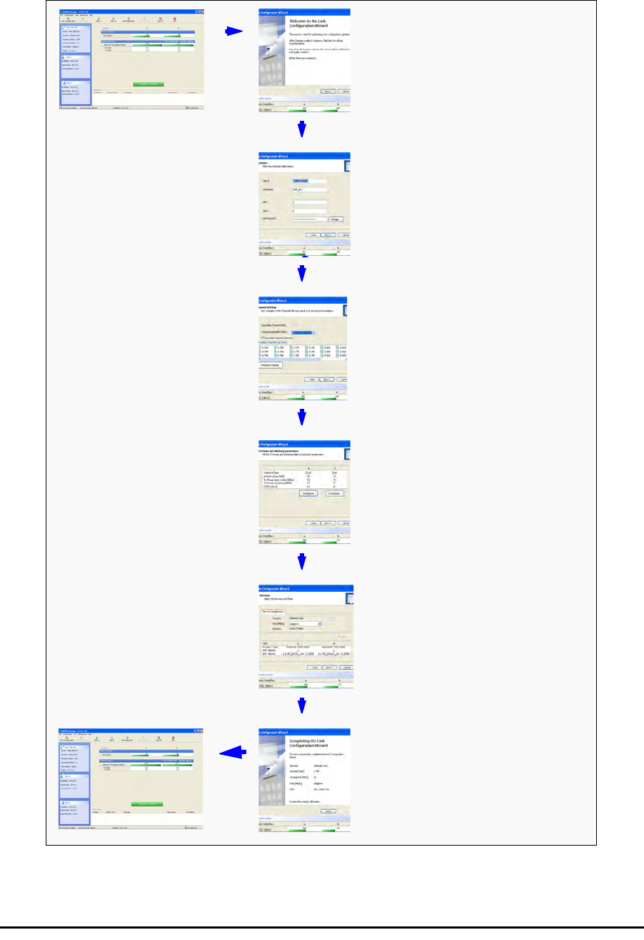
Configuring the Link: Overview Chapter 5
RADWIN 1000/2000/3000 User ManualVersion 2.5.30p1 5-10
Configuring the Link: Overview
The Configuration Wizard has seven steps as shown in table 5-6 below.
Table 5-6: Link Configuration Wizard
1Wizard welcome
2System parameters
•Link ID
• Site details
3Channel settings
4Tx power settings
5Services
6Wizard summary and
completion
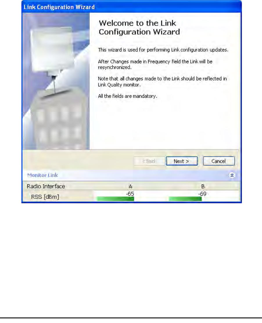
Configuring the Link: Step 1, Start the Wizard Chapter 5
RADWIN 1000/2000/3000 User ManualVersion 2.5.30p1 5-11
Since configuration functionality is included in the installation, we will briefly
review the main steps and for most part offer references to the correspond-
ing installation step.
Configuring the Link: Step 1, Start the Wizard
In the tool bar of the RADWIN Manager main window, click the Link Con-
figuration button. The Link Configuration button is only accessible on a
fully installed link as set out in chapter 4.
The Configuration Wizard opens:
Figure 5-3: Link Configuration Wizard
Click Next to proceed with the configuration procedure.
Configuring the Link: Step 2, System Parameters
The System dialog box opens:
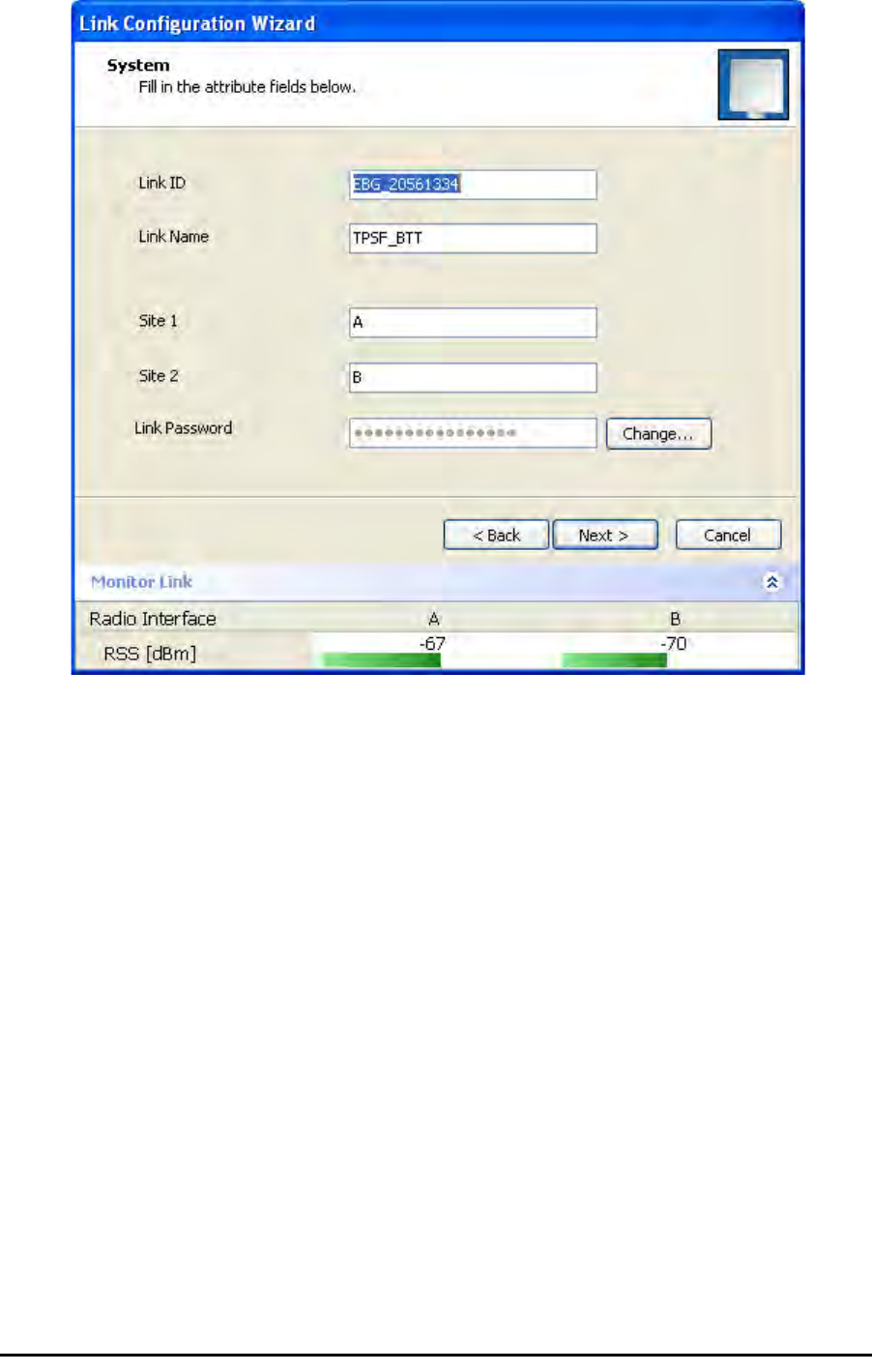
Configuring the Link: Step 3, Channel Settings Chapter 5
RADWIN 1000/2000/3000 User ManualVersion 2.5.30p1 5-12
Figure 5-4: Configuration Wizard, System dialog box
The System attributes may be edited and the Link Password may be
changed exactly as in the corresponding Link Installation step on page 4-
14.
Click Next to continue.
Configuring the Link: Step 3, Channel Settings
Configuring the Channel Settings follows the same pattern as the Installa-
tion procedure:
Configuring the Link: Step 3, Channel Settings Chapter 5
RADWIN 1000/2000/3000 User ManualVersion 2.5.30p1 5-13
Figure 5-5: Channel Settings dialog box - Automatic Channel Selection
Notice that the operating channel is grayed out. If you use the Reselect
Channel button, to change it, you will be asked for confirmation:
If you accept, then the system will search for the best operating channel:
Configuring the Link: Step 3, Channel Settings Chapter 5
RADWIN 1000/2000/3000 User ManualVersion 2.5.30p1 5-14
Figure 5-6: Searching for the best operating channel
The link will return to the status of figure 5-5 above with a possible
change to the operating channel.
If you work without automatic channel selection, the Channel Settings win-
dow looks like this:
Configuring the Link: Step 3, Channel Settings Chapter 5
RADWIN 1000/2000/3000 User ManualVersion 2.5.30p1 5-15
Figure 5-7: Channel Settings without automatic channel selection
If you click the Operating Channel drop-down list, the following window
appears:
Configuring the Link: Step 3, Channel Settings Chapter 5
RADWIN 1000/2000/3000 User ManualVersion 2.5.30p1 5-16
Figure 5-8: Channel frequency options
Selecting one of the frequencies presented returns you to the status of
figure 5-7 with the appropriate change. If you choose Other..., the follow-
ing window opens:
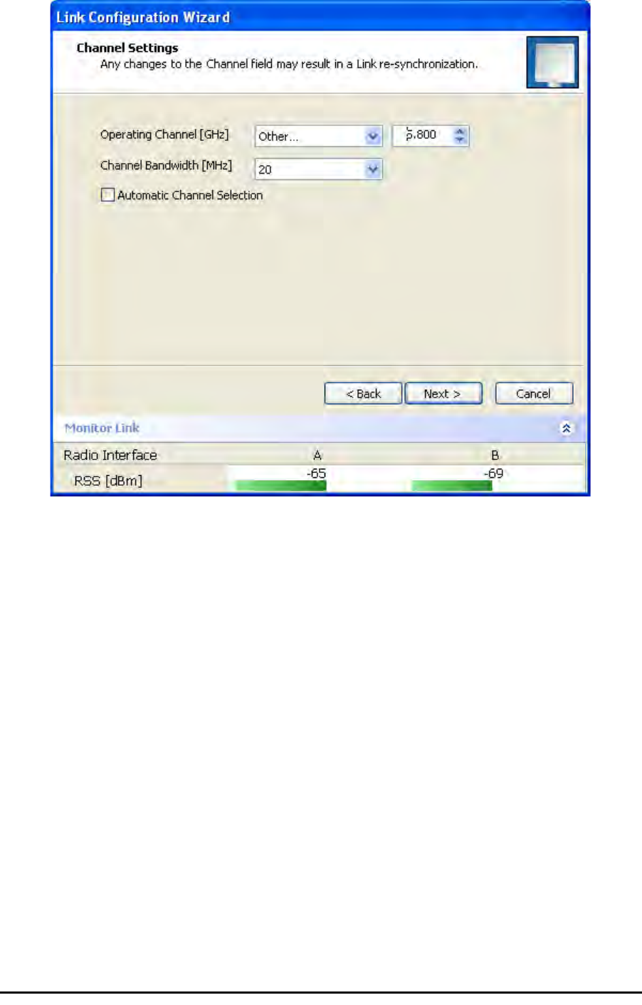
Configuring the Link: Step 3, Channel Settings Chapter 5
RADWIN 1000/2000/3000 User ManualVersion 2.5.30p1 5-17
Figure 5-9: Choosing an “Other” Operating Channel frequency
The right hand drop-down list (showing 5.800) allows you to fine-tune the
frequency in increments of ±5MHz within a range of 5.740 - 5.835 GHz.
When you have completed making your choice, click Next to continue.
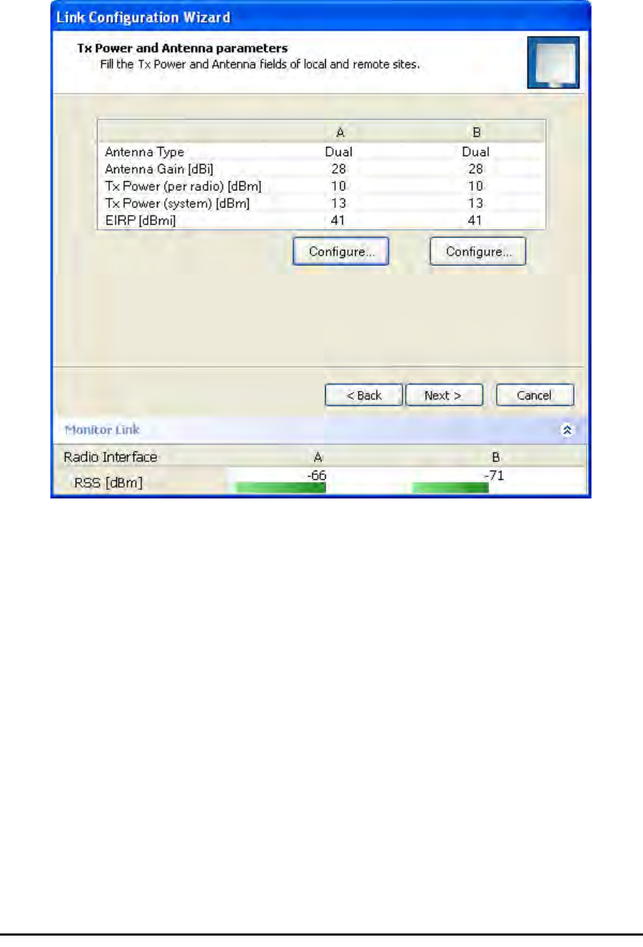
Configuring the Link: Step 4, Tx Power and Antenna Settings Chapter 5
RADWIN 1000/2000/3000 User ManualVersion 2.5.30p1 5-18
Configuring the Link: Step 4, Tx Power and Antenna
Settings
.
Figure 5-10: Transmission Power and Antenna Parameters
If you chose to configure either antenna, you are presented with the follow-
ing window:
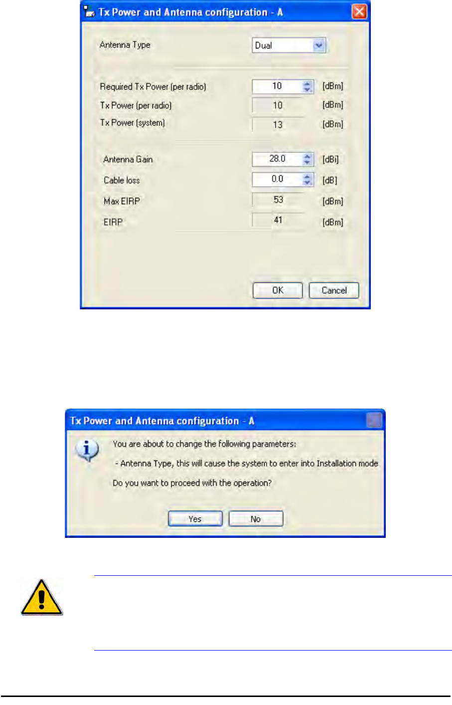
Configuring the Link: Step 4, Tx Power and Antenna Settings Chapter 5
RADWIN 1000/2000/3000 User ManualVersion 2.5.30p1 5-19
Figure 5-11: Antenna configuration dialog with opened type selection
So far, the procedure duplicates the corresponding Installation process on.
If you choose a different antenna type and click OK, you will receive the fol-
lowing cautionary message:
Caution
In this context, entering Installation mode causes a service break until it is
restored by running the Installation wizard.
If you are uncertain, do not do this without expert technical
assistance.
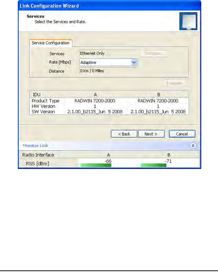
Configuring the Link: Step 5, Services Chapter 5
RADWIN 1000/2000/3000 User ManualVersion 2.5.30p1 5-20
You may also change the Required Tx Power, Antenna Gain and Cable Loss.
The procedure is the same as that set out in the Installation procedure on
page 4-23.
When you have completed making your choice, proceed to the Services
window.
Configuring the Link: Step 5, Services
Here is the services dialog:
.
Figure 5-12: Services and Rates dialog
To choose Services, see the corresponding Installation procedure on
page 5-20.
Click Next to continue.
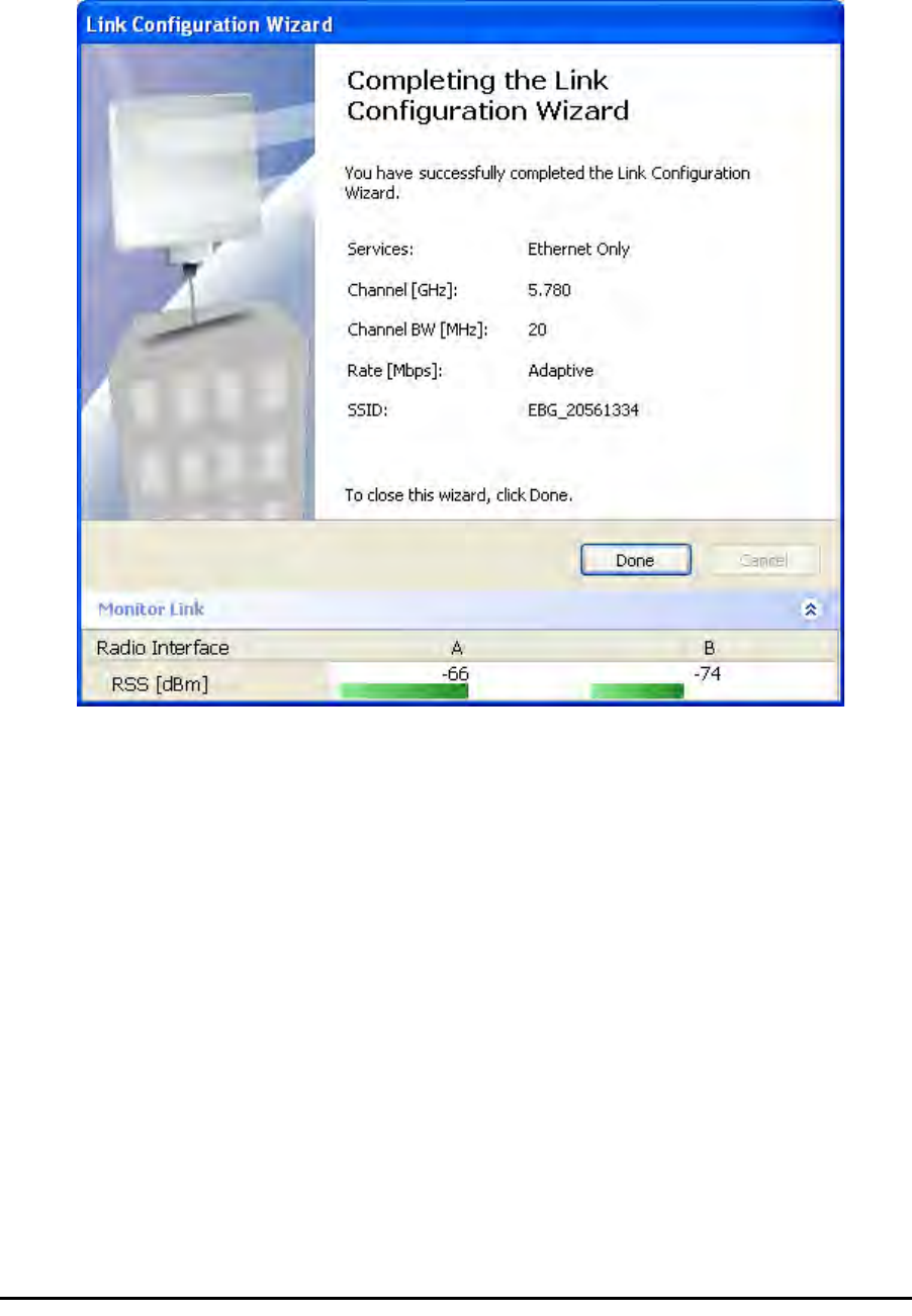
Configuring the Link: Step 6, Configuration Summary and Exit Chapter 5
RADWIN 1000/2000/3000 User ManualVersion 2.5.30p1 5-21
Configuring the Link: Step 6, Configuration Summary and
Exit
Figure 5-13: Configuration Wizard Exit Summary
Click Done to return to the main window.
The main window now reflects the configuration:
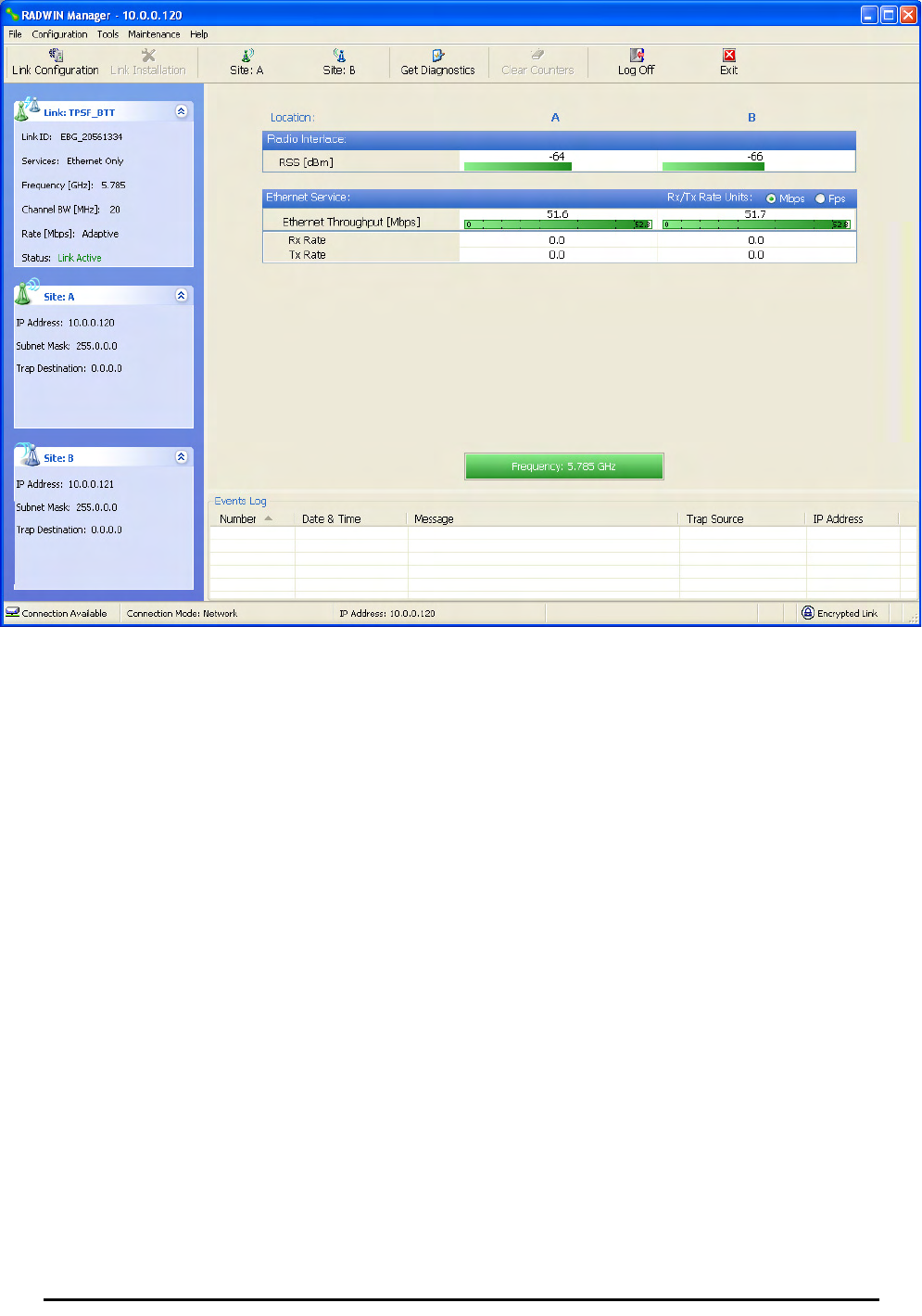
Configuring the Link: Step 6, Configuration Summary and Exit Chapter 5
RADWIN 1000/2000/3000 User ManualVersion 2.5.30p1 5-22
Figure 5-14: Main window of the manager after configuration