Radwin RW2058U Outdoor radio unit operating in 5.8 GHz bands User Manual STW
Radwin Ltd. Outdoor radio unit operating in 5.8 GHz bands STW
UserManual.wiki
>
Radwin
>
RW2058U User Manual
>
Manual U4
Contents
1.
Manual U1
2.
Manual U2
3.
Manual U3
4.
Manual U4
5.
Manual
Manual U4
Navigation menu
Upload a User Manual
Namespaces
Wiki Guide
HTML
PDF
Info
Views
User Manual
Discussion / Help
Navigation
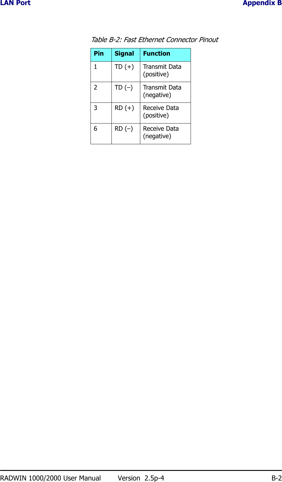
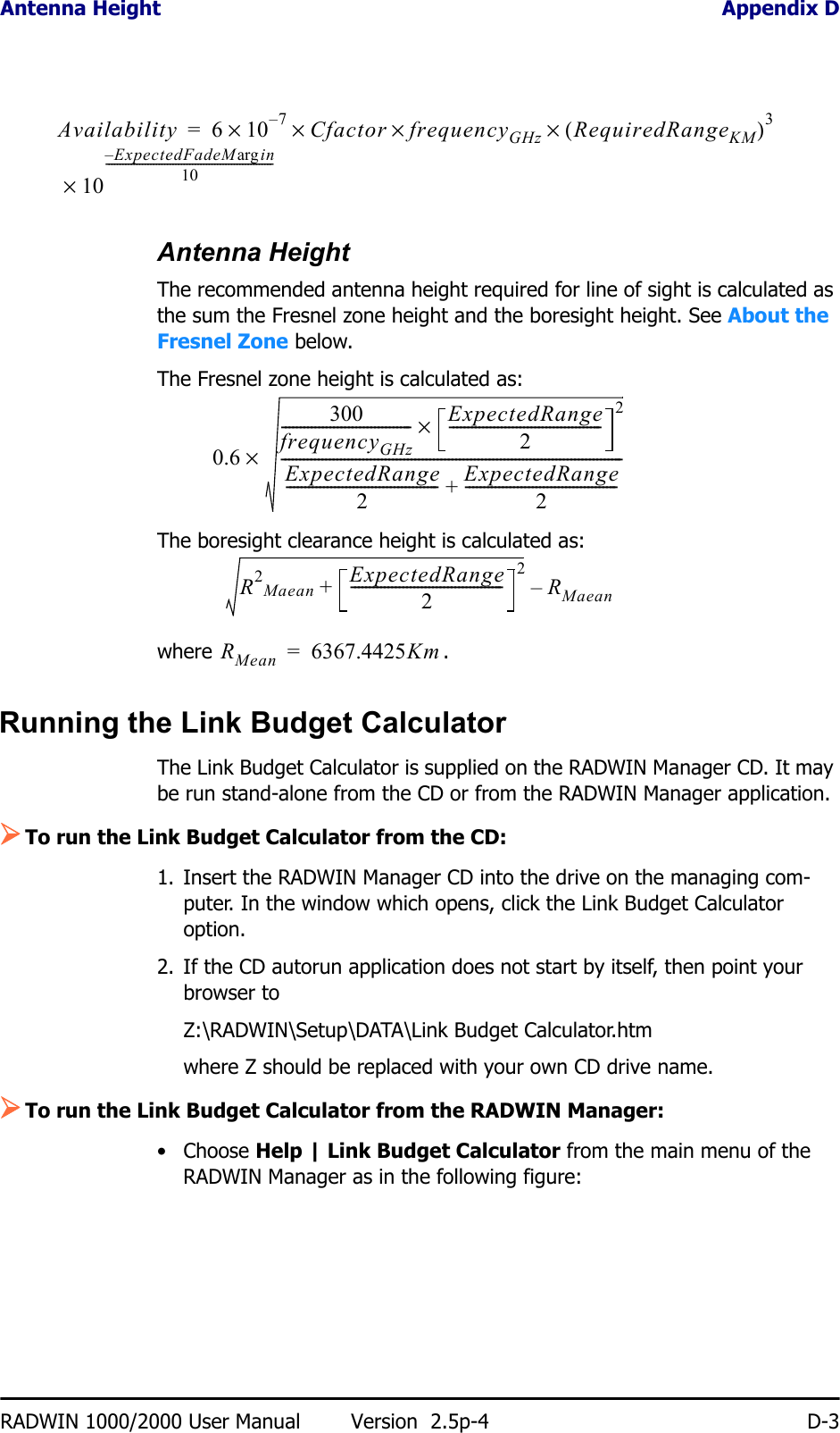
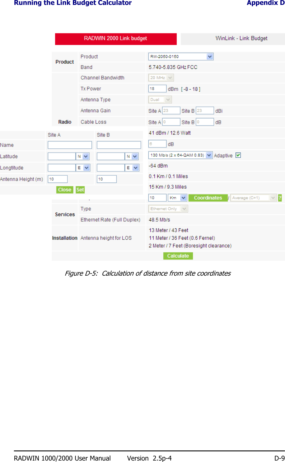
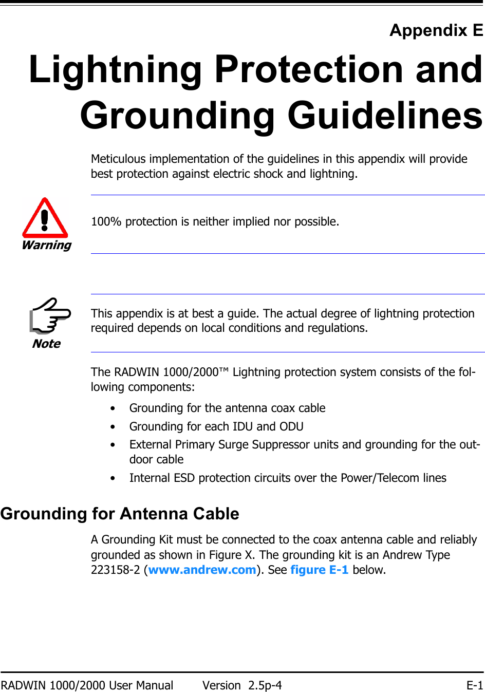
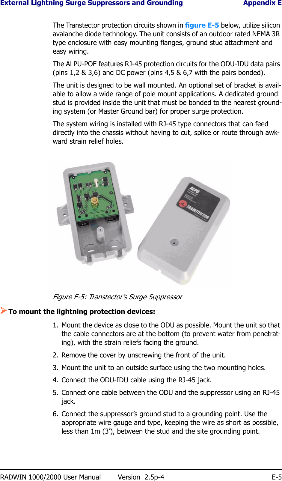
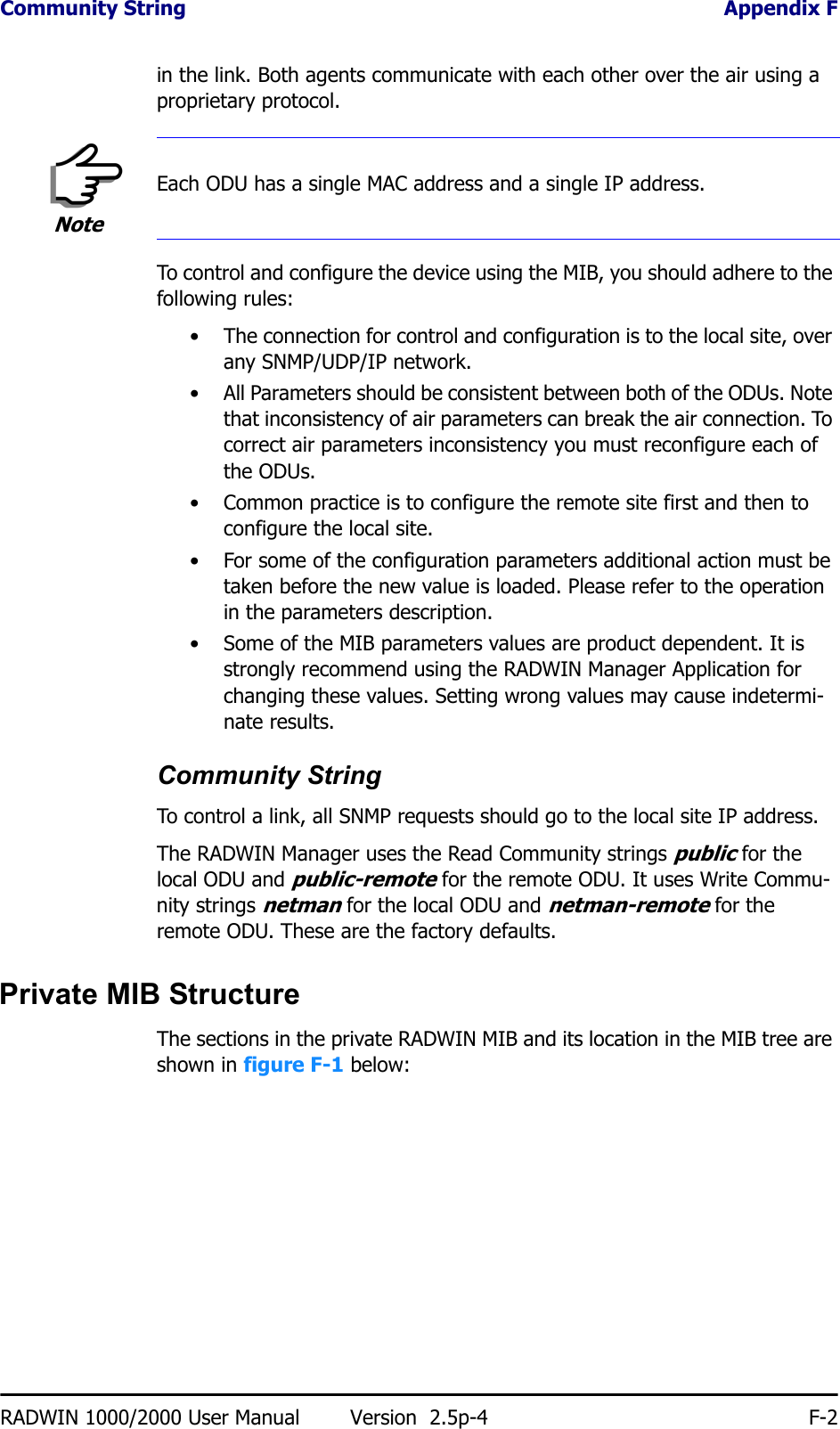
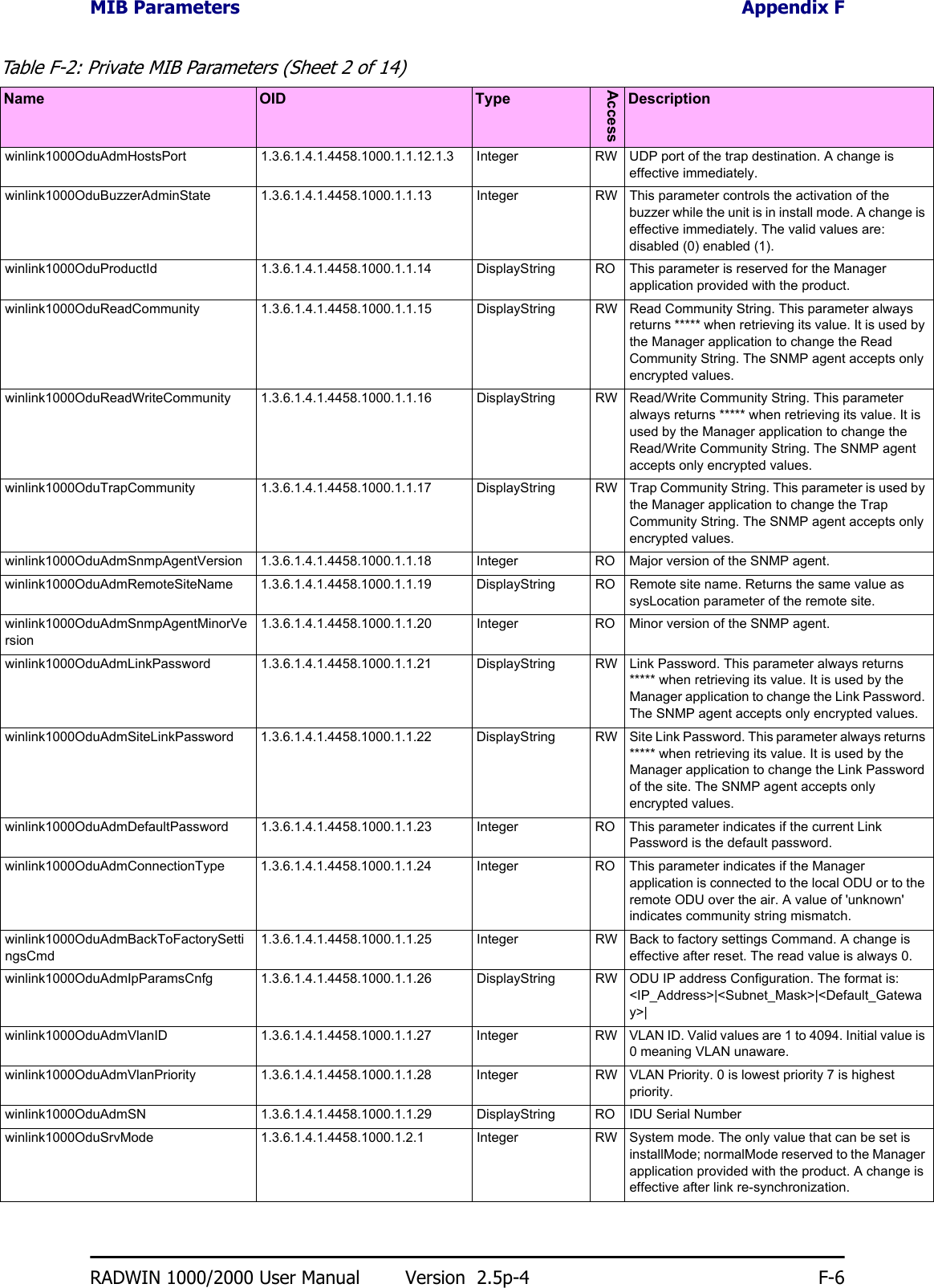
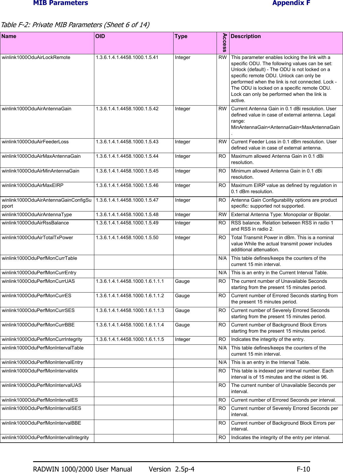
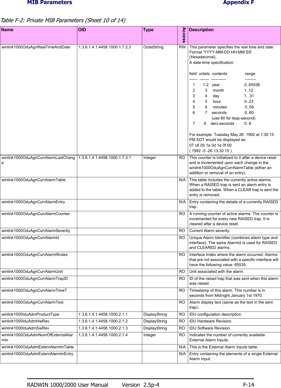
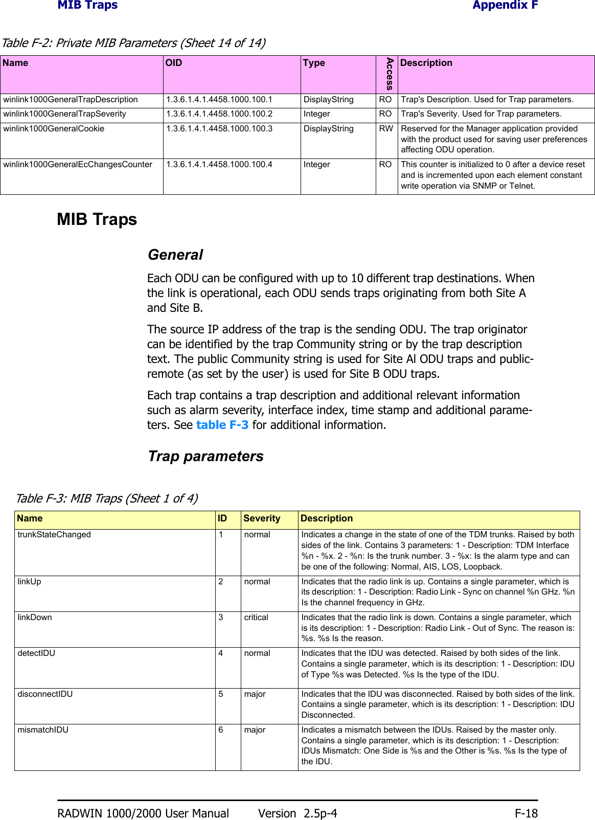
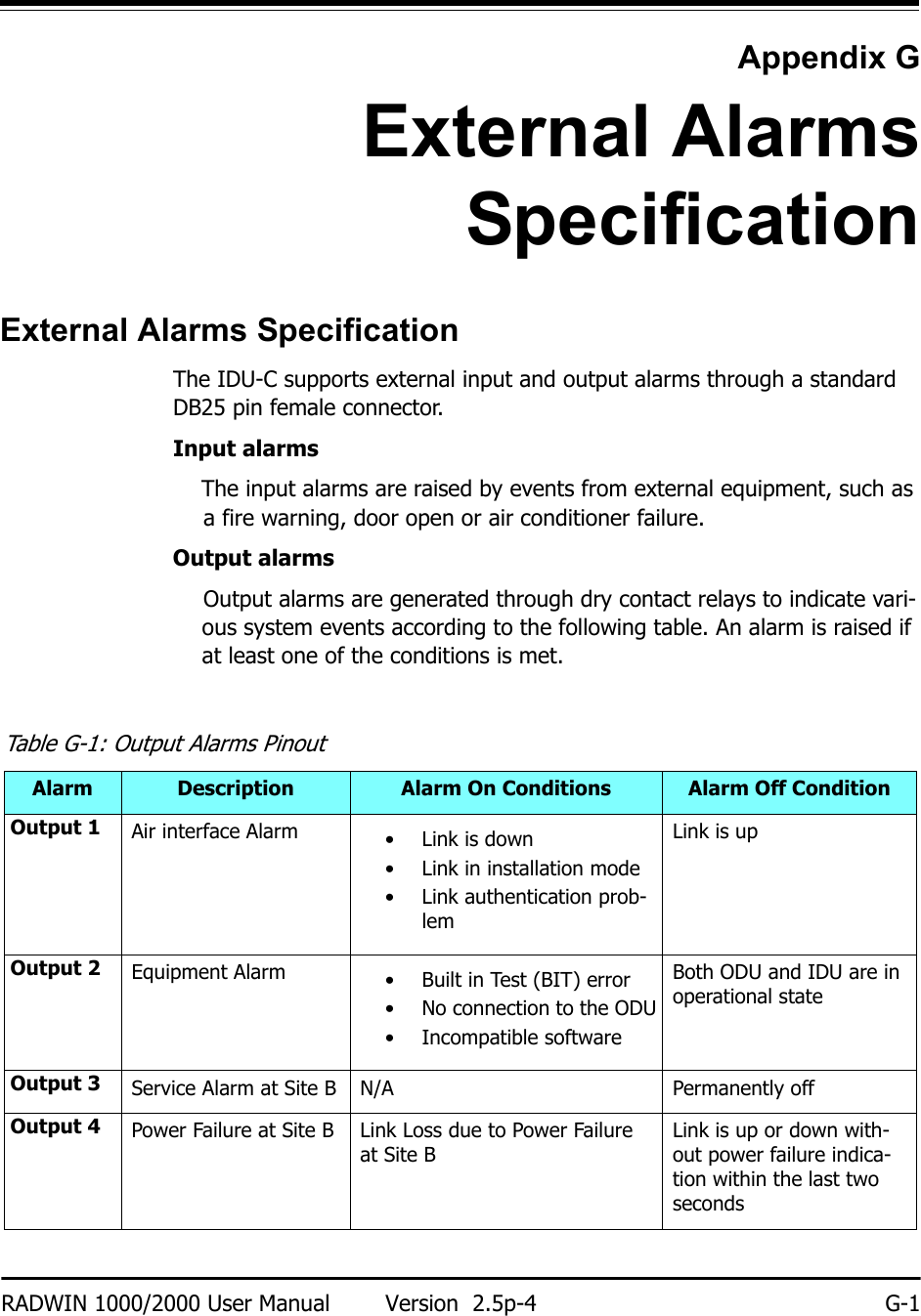
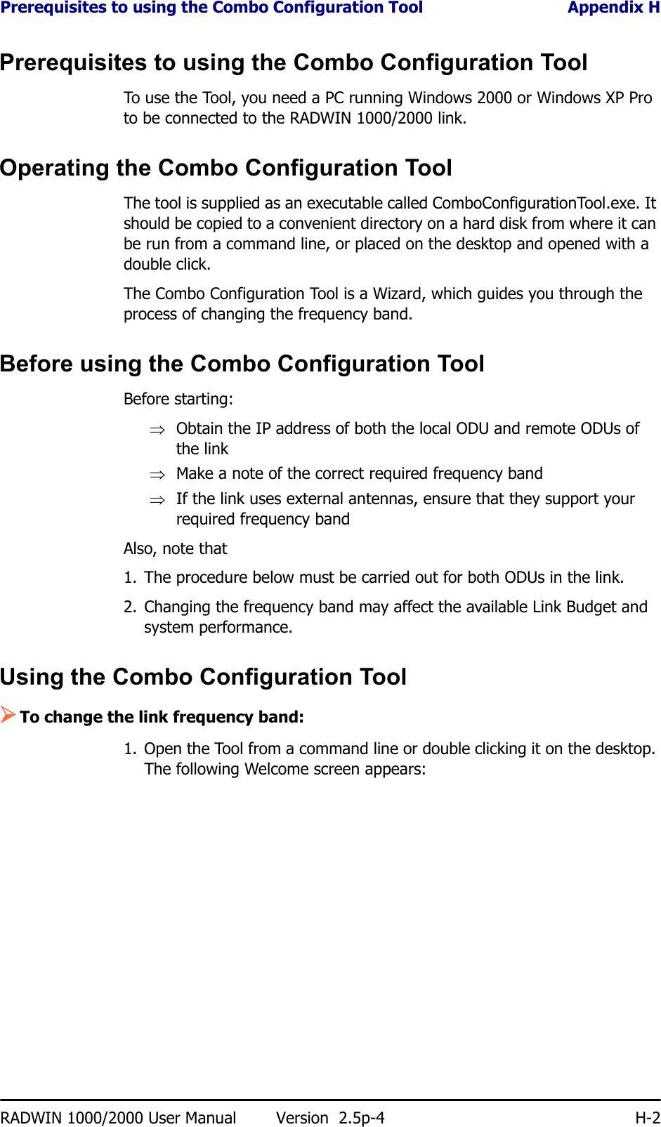
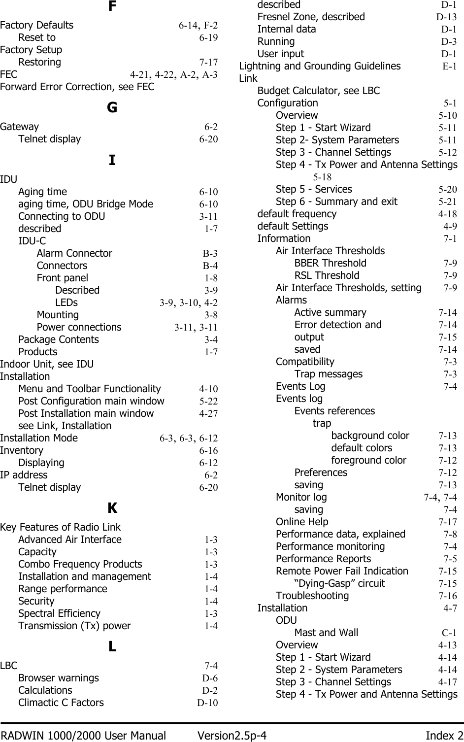
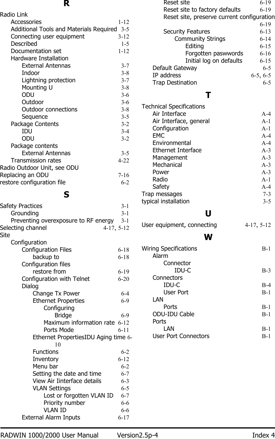
![Radio Appendix ARADWIN 1000/2000 User Manual Version 2.5p-4 A-2Channel Bandwidth5, 10, and 20 MHz40 MHz in the 5.3/5.4 IC and 5.8 GHz spectrum bandsMax Tx PowerBand5.725 – 5.850 GHz5.725 – 5.850 GHz5.725 – 5.850 GHz5.250 – 5.350 GHz5.250 – 5.350 GHz5.250 – 5.350 GHz5.250 – 5.350 GHz IC5.470 – 5.725 GHz5.470 – 5.725 GHz5.470 – 5.725 GHz5.470 – 5.725 GHz IC5.725 – 5.825 GHz5.725 – 5.825 GHz5.725 – 5.825 GHz5.725 – 5.825 GHz4.940 – 4.990 GHz 4.940 – 4.990 GHz 4.940 – 4.990 GHz2.400 – 2.4835 GHz2.400 – 2.4835 GHz2.400 – 2.4835 GHz2.400 – 2.4835 GHzPower29.95 dBm 29.95 dBm29.95 dBm1.9 dBm6.5 dBm7.5 dBm23.5dBm1.6 dBm6.3 dBm7.3 dBm23.7 dBm23.8 dBm26.4 dBm26.4 dBm29.4 dBm31 dBm31 dBm31 dBm25.5 dBm*25.5 dBm*23.7 dBm23.7 dBmAntenna28 dBi Dish24 dBi Integral Flat23 dBi External Flat28 dBi Dish23.5 dBi Integral Flat22.5 dBi External Flat6 dBi assembly28 dBi Dish23.5 dBi Integral Flat22.5 dBi External Flat6 dBi assembly28 dBi Dish22.5 dBi Integral Flat23.5 dBi External Flat6 dBi assembly21 dBi Integral Flat21 dBi External Flat28 dBi Dish20 dBi External Flat17.5 dBi Integral Flat20 dBi External Flat17.5 dBi Integral FlatChannel Bandwidth 5, 10, and 20 MHz, (10MHz not supported in the 5.8 GHz band)Radio Modulation 2x2 MIMO-OFDM (BPSK/QPSK/16QAM/64QAM)Adaptive Modulation & Coding SupportedAutomatic Channel Selection SupportedRadio RegulationFCC 47 CFR Part 15 Subpart C, EIC (Canada) RSS-210 and RSS-111Duplex Technology TDDError Correction FEC k = 1/2, 2/3, 3/4, 5/6Rate – Single Antenna [Mbps] 6.5 13 19.5 26 39 52 58.5 65Rate – Single Antenna in the 5.8 GHz spectrum band [Mbps]13.5 27 40.5 54 81 108 121.5 135Rate – Dual Antenna [Mbps] 13 26 39 52 78 104 117 130](https://usermanual.wiki/Radwin/RW2058U.Manual-U4/User-Guide-1314855-Page-2.png)
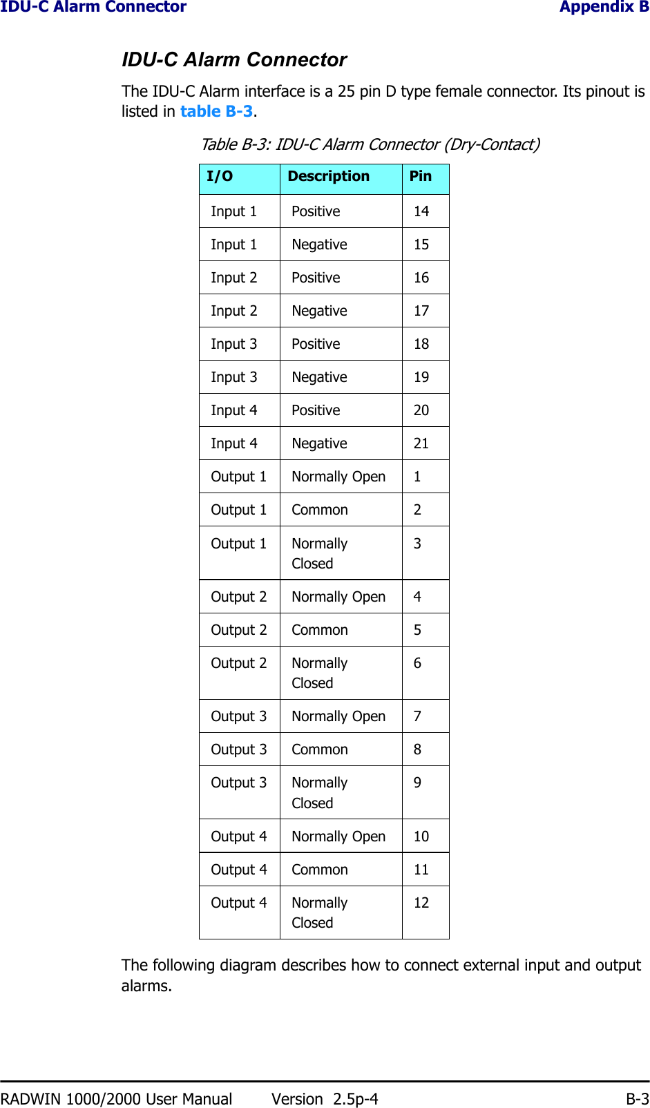
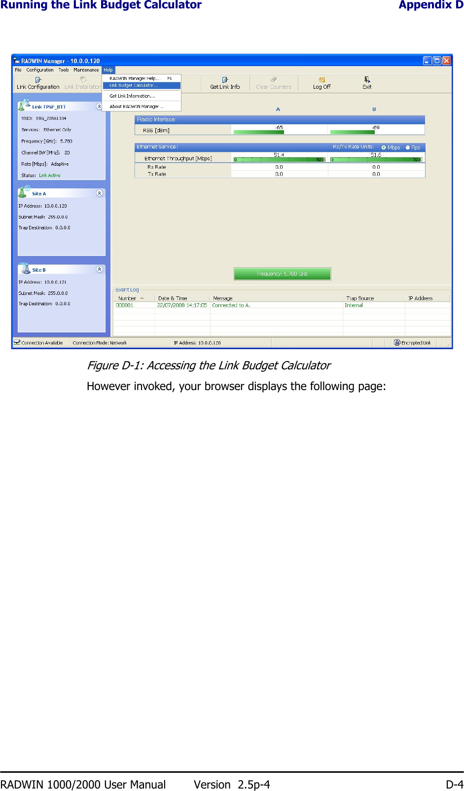
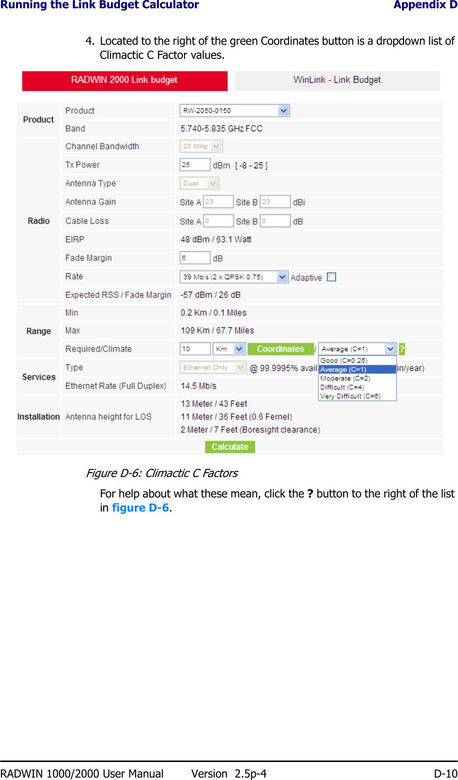
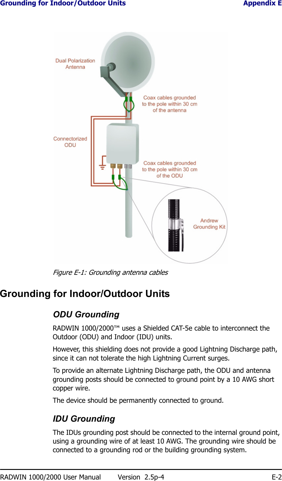
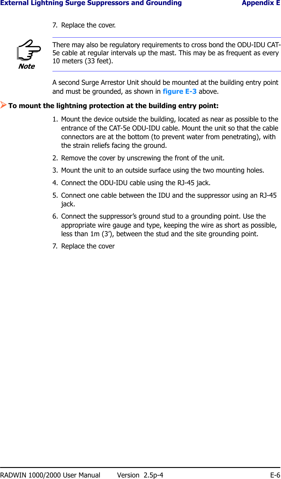
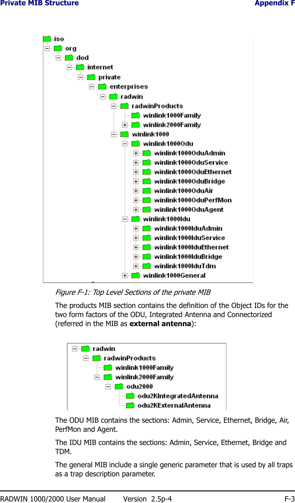
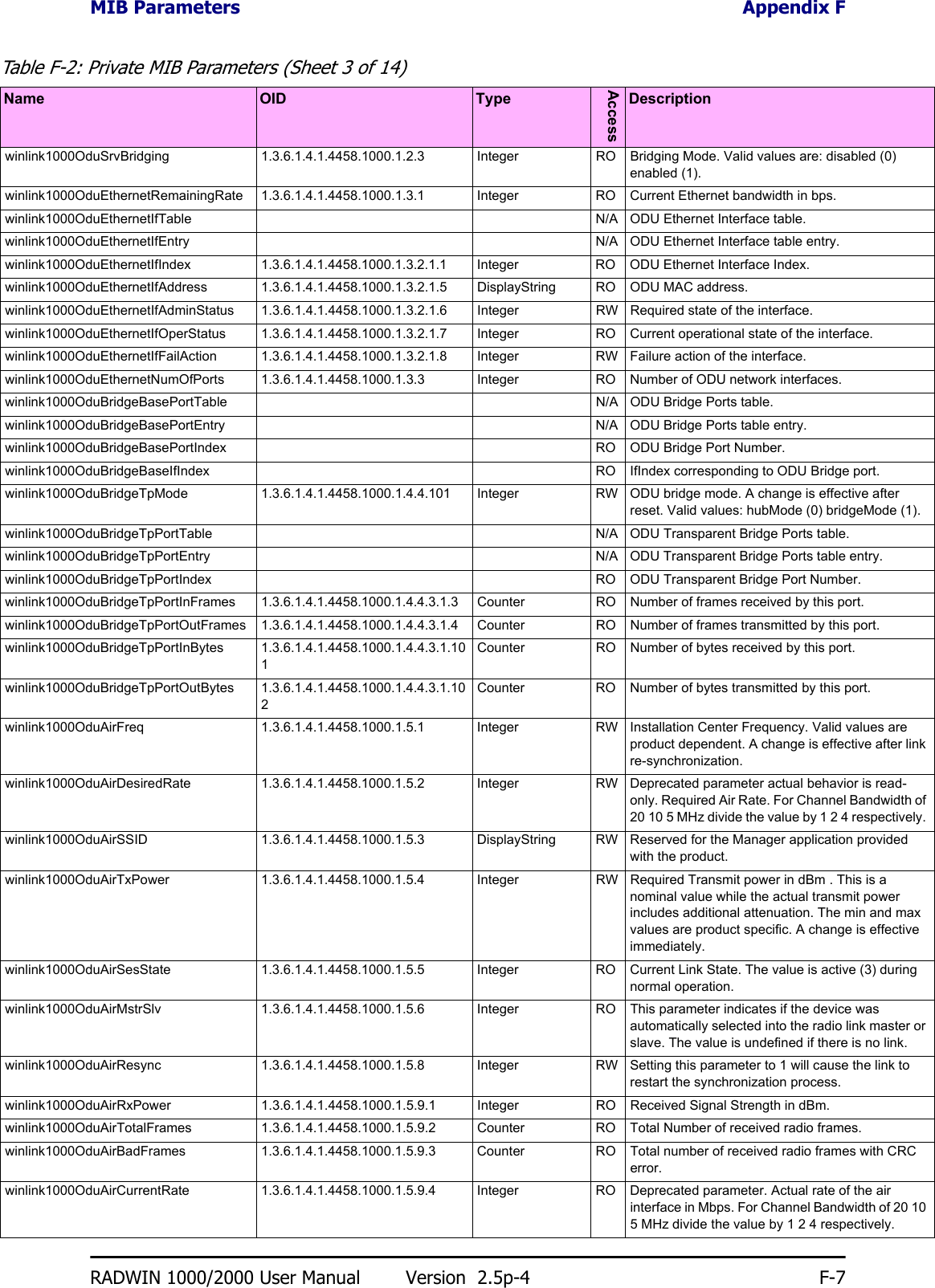
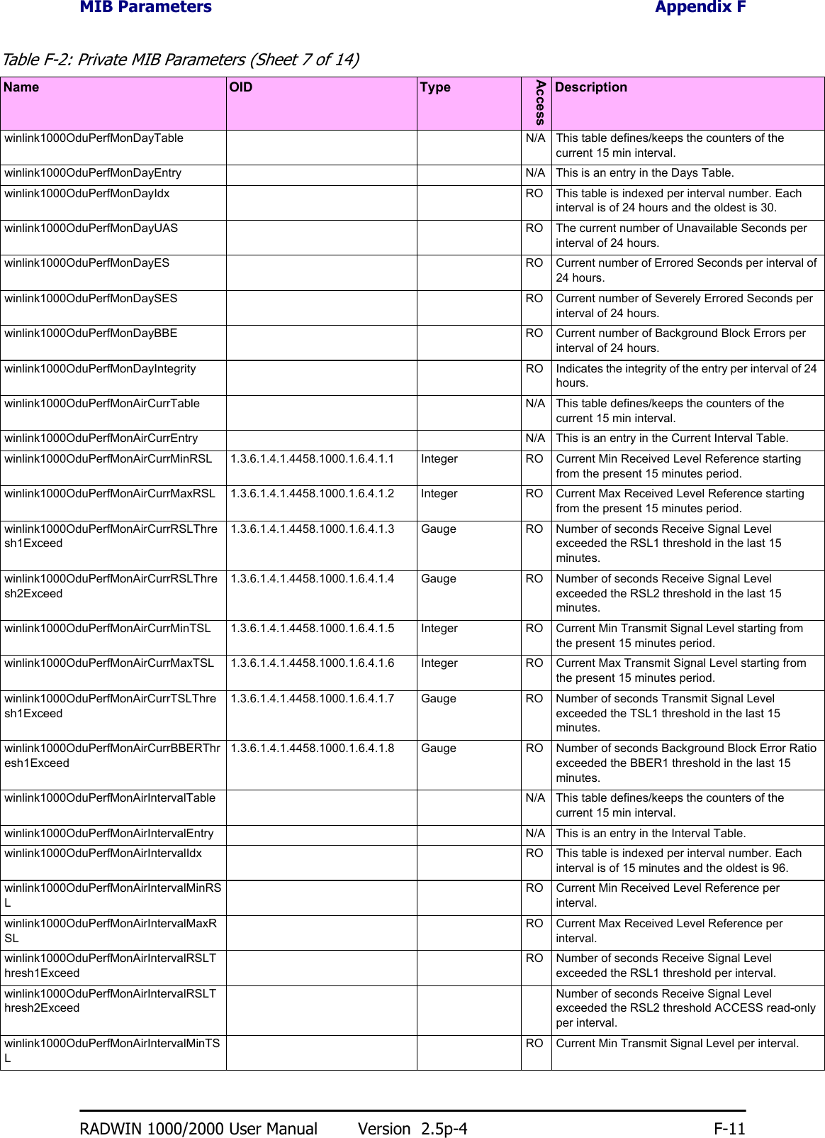
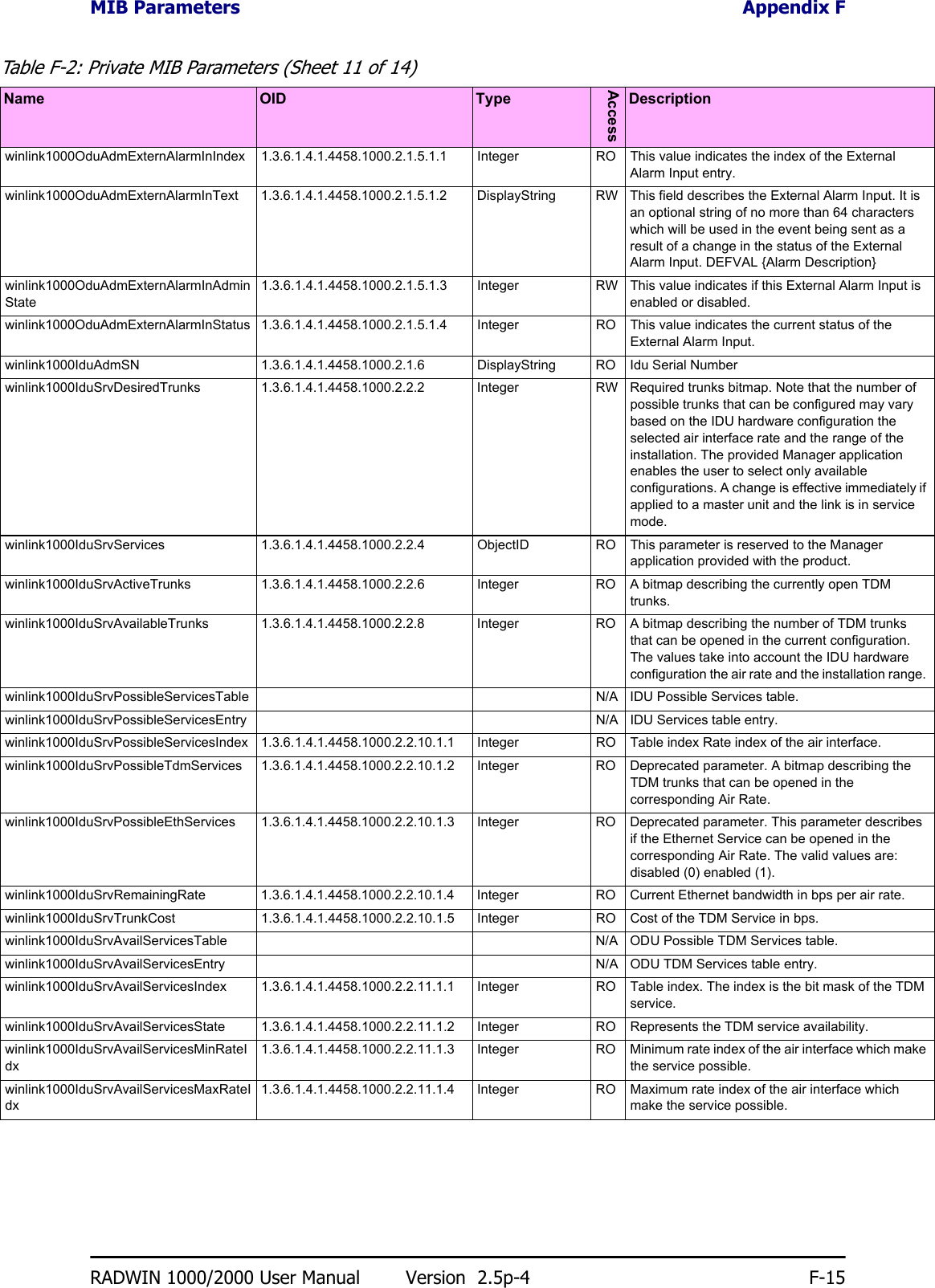
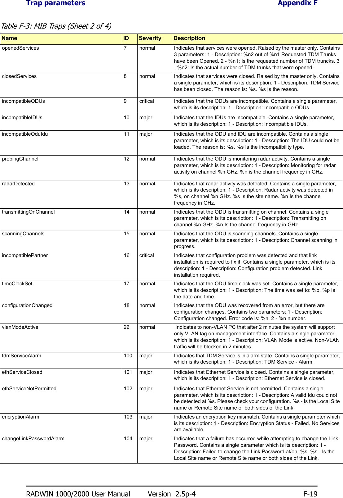
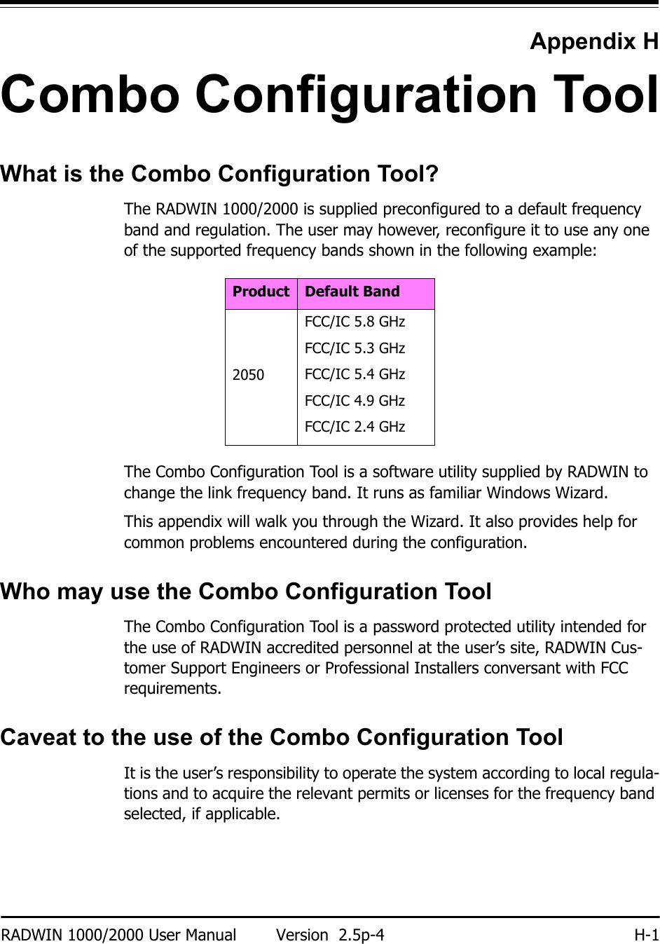
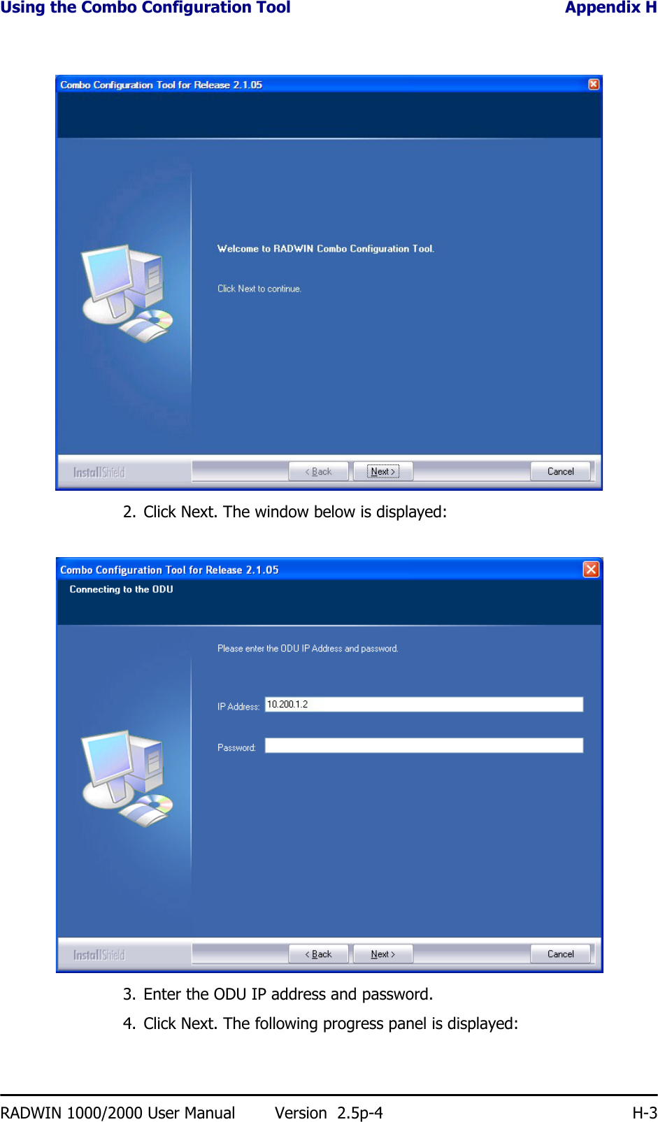
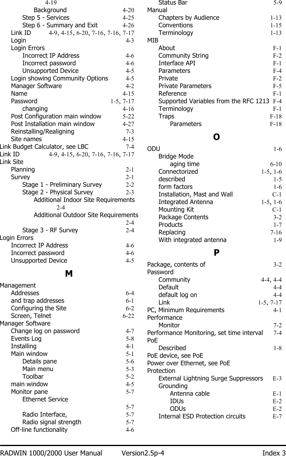
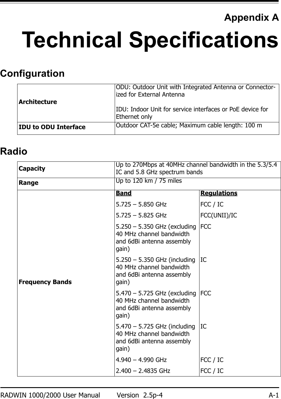
![Ethernet Interface Appendix ARADWIN 1000/2000 User Manual Version 2.5p-4 A-3* Relevant for RADWIN 1000 RW-1020-0150 / RADWIN 2000 RW-2020-0150 models onlyEthernet InterfaceManagementMechanicalPowerRate –Dual Antenna in the 5.8 GHz spectrum band [Mbps]27 54 81 108 162 216 243 270Modulation BPSK QPSK 16QAM 64QAMFEC [k=] 1/2 1/2 3/4 1/2 3/4 2/3 3/4 5/6Max Tx Power [dBm] 25 24 21 19 18Sensitivity (dBm) @BER <10e-11 (20MHz)-88 -86 -83 -81 -80 -72 -70 -67Encryption AES 128Throughput Up to 270Mbps in the 5.3/5.4 IC and 5.8 GHz spectrum bandsNumber of Ethernet ports IDU-C: 2; PoE Device: 1Type 10/100BaseT with Auto-Negotiation (IEEE 802.3u)Framing/Coding IEEE 802.3Line Impedance 100 ΩVLAN Support TransparentConnector RJ-45Maximum Frame Size 2048 BytesBridge Layer 2, self-learning of up to 2047 MAC addresses (IEEE 802.1Q), hub/Bridge selectable modeLatency 3 msec (typical)Management Application RADWIN ManagerProtocol SNMP and TelnetDimensionsODU with Integrated Antenna: 37.1/14.84(W) x 37.1/14.84(H) x 9.00/3.6(D) cm/in; 3.5 kg / 7 lbsODU Connectorized: 18.0/7.2(W) x 27.0/10.8(H) x 5.5/2.2(D) cm/in; 1.5 kg / 3.0 lbsIDU: 43.6/17.2(W) x 4.5/1.7(H) x 21/8.3(D) cm; 1.5 kg / 3.3 lbs](https://usermanual.wiki/Radwin/RW2058U.Manual-U4/User-Guide-1314855-Page-3.png)