Radwin RW2058U Outdoor radio unit operating in 5.8 GHz bands User Manual STW
Radwin Ltd. Outdoor radio unit operating in 5.8 GHz bands STW
Radwin >
Contents
- 1. Manual U1
- 2. Manual U2
- 3. Manual U3
- 4. Manual U4
- 5. Manual
Manual U4

RADWIN 1000/2000 User Manual Version 2.5p-4 A-1
Appendix A
Technical Specifications
Configuration
Radio
Architecture
ODU: Outdoor Unit with Integrated Antenna or Connector-
ized for External Antenna
IDU: Indoor Unit for service interfaces or PoE device for
Ethernet only
IDU to ODU Interface Outdoor CAT-5e cable; Maximum cable length: 100 m
Capacity Up to 270Mbps at 40MHz channel bandwidth in the 5.3/5.4
IC and 5.8 GHz spectrum bands
Range Up to 120 km / 75 miles
Frequency Bands
Band
5.725 – 5.850 GHz
5.725 – 5.825 GHz
5.250 – 5.350 GHz (excluding
40 MHz channel bandwidth
and 6dBi antenna assembly
gain)
5.250 – 5.350 GHz (including
40 MHz channel bandwidth
and 6dBi antenna assembly
gain)
5.470 – 5.725 GHz (excluding
40 MHz channel bandwidth
and 6dBi antenna assembly
gain)
5.470 – 5.725 GHz (including
40 MHz channel bandwidth
and 6dBi antenna assembly
gain)
4.940 – 4.990 GHz
2.400 – 2.4835 GHz
Regulations
FCC / IC
FCC(UNII)/IC
FCC
IC
FCC
IC
FCC / IC
FCC / IC

Radio Appendix A
RADWIN 1000/2000 User Manual Version 2.5p-4 A-2
Channel Bandwidth
5, 10, and 20 MHz
40 MHz in the 5.3/5.4 IC and 5.8 GHz spectrum bands
Max Tx Power
Band
5.725 – 5.850 GHz
5.725 – 5.850 GHz
5.725 – 5.850 GHz
5.250 – 5.350 GHz
5.250 – 5.350 GHz
5.250 – 5.350 GHz
5.250 – 5.350 GHz IC
5.470 – 5.725 GHz
5.470 – 5.725 GHz
5.470 – 5.725 GHz
5.470 – 5.725 GHz IC
5.725 – 5.825 GHz
5.725 – 5.825 GHz
5.725 – 5.825 GHz
5.725 – 5.825 GHz
4.940 – 4.990 GHz
4.940 – 4.990 GHz
4.940 – 4.990 GHz
2.400 – 2.4835 GHz
2.400 – 2.4835 GHz
2.400 – 2.4835 GHz
2.400 – 2.4835 GHz
Power
29.95 dBm
29.95 dBm
29.95 dBm
1.9 dBm
6.5 dBm
7.5 dBm
23.5dBm
1.6 dBm
6.3 dBm
7.3 dBm
23.7 dBm
23.8 dBm
26.4 dBm
26.4 dBm
29.4 dBm
31 dBm
31 dBm
31 dBm
25.5 dBm*
25.5 dBm*
23.7 dBm
23.7 dBm
Antenna
28 dBi Dish
24 dBi Integral Flat
23 dBi External Flat
28 dBi Dish
23.5 dBi Integral Flat
22.5 dBi External Flat
6 dBi assembly
28 dBi Dish
23.5 dBi Integral Flat
22.5 dBi External Flat
6 dBi assembly
28 dBi Dish
22.5 dBi Integral Flat
23.5 dBi External Flat
6 dBi assembly
21 dBi Integral Flat
21 dBi External Flat
28 dBi Dish
20 dBi External Flat
17.5 dBi Integral Flat
20 dBi External Flat
17.5 dBi Integral Flat
Channel Bandwidth 5, 10, and 20 MHz, (10MHz not supported in the 5.8 GHz
band)
Radio Modulation 2x2 MIMO-OFDM (BPSK/QPSK/16QAM/64QAM)
Adaptive Modulation & Coding Supported
Automatic Channel Selection Supported
Radio Regulation
FCC 47 CFR Part 15 Subpart C, E
IC (Canada) RSS-210 and RSS-111
Duplex Technology TDD
Error Correction FEC k = 1/2, 2/3, 3/4, 5/6
Rate – Single Antenna [Mbps] 6.5 13 19.5 26 39 52 58.5 65
Rate – Single Antenna in the
5.8 GHz spectrum band
[Mbps]
13.5 27 40.5 54 81 108 121.5 135
Rate – Dual Antenna [Mbps] 13 26 39 52 78 104 117 130

Ethernet Interface Appendix A
RADWIN 1000/2000 User Manual Version 2.5p-4 A-3
* Relevant for RADWIN 1000 RW-1020-0150 / RADWIN 2000 RW-2020-
0150 models only
Ethernet Interface
Management
Mechanical
Power
Rate –Dual Antenna in the 5.8
GHz spectrum band [Mbps]
27 54 81 108 162 216 243 270
Modulation BPSK QPSK 16QAM 64QAM
FEC [k=] 1/2 1/2 3/4 1/2 3/4 2/3 3/4 5/6
Max Tx Power [dBm] 25 24 21 19 18
Sensitivity (dBm) @BER <10e-
11 (20MHz)
-88 -86 -83 -81 -80 -72 -70 -67
Encryption AES 128
Throughput Up to 270Mbps in the 5.3/5.4 IC and 5.8 GHz spectrum
bands
Number of Ethernet ports IDU-C: 2; PoE Device: 1
Type 10/100BaseT with Auto-Negotiation (IEEE 802.3u)
Framing/Coding IEEE 802.3
Line Impedance 100 Ω
VLAN Support Transparent
Connector RJ-45
Maximum Frame Size 2048 Bytes
Bridge Layer 2, self-learning of up to 2047 MAC addresses (IEEE
802.1Q), hub/Bridge selectable mode
Latency 3 msec (typical)
Management Application RADWIN Manager
Protocol SNMP and Telnet
Dimensions
ODU with Integrated Antenna: 37.1/14.84(W) x 37.1/
14.84(H) x 9.00/3.6(D) cm/in; 3.5 kg / 7 lbs
ODU Connectorized: 18.0/7.2(W) x 27.0/10.8(H) x 5.5/
2.2(D) cm/in; 1.5 kg / 3.0 lbs
IDU: 43.6/17.2(W) x 4.5/1.7(H) x 21/8.3(D) cm; 1.5 kg / 3.3
lbs

Environmental Appendix A
RADWIN 1000/2000 User Manual Version 2.5p-4 A-4
Environmental
Safety
EMC
Air Interface
RADWIN 1000/2000 is available in several different frequency band ranges
that comply with ETSI, FCC and IC regulations.
The RADWIN 1000 RW-1020-0150 / RADWIN 2000 RW-2020-0150 is avail-
able only in the 2.4GHz frequency band range that complies with FCC and
IC regulations
Power Feeding Dual feeding, -20 to -60 VDC (AC/DC converter is available)
Power Consumption < 35 W (IDU+ODU)
Operating Temperatures
ODU: -35°C to +60°C / -31°F to +140°F
IDU: 0°C to +50°C / 32°F to +122°F
Humidity
ODU: Up to 100% non-condensing, IP67
IDU: 90% non-condensing
FCC/IC (cTUVus) UL 60950-1, CAN/CSA 60950-1 C22.2
ETSI EN/IEC 60950-1
FCC CFR47 Class B, Part15, Subpart B
ETSI EN 300 386 (2005), EN 301 489-1 (2001), EN 301 489-4
(2002)
CAN/CSA-CEI/IEC CISPR 22-02
AS/NZS CISPR 22:2002

RADWIN 1000/2000 User Manual Version 2.5p-4 B-1
Appendix B
Wiring Specifications
ODU-IDU Cable
The ODU-IDU cable is shielded/outdoor class CAT-5e, 4 twisted-pair 24
AWG terminated with RJ-45 connectors on both ends. A cable gland on the
ODU side provides hermetic sealing.
The following table shows the connector pinout:
User Port Connectors
LAN Port
The LAN 10/100BaseT interface terminates in an 8-pin RJ-45 connector,
wired in accordance to table B-2.
Table B-1: ODU-IDU Connector Pinout
Function Color IDU RJ-45 ODU
RJ-45
Ethernet (RxN) White/Green 1 twisted
2 pair
1
Ethernet (RxT) Green 2
Ethernet (TxT) White/Orange 3 twisted
6 pair
3
Ethernet (TxN) Orange 6
Power (+) Blue 4 twisted
5 pair
4
Power (+) White/Blue 5
Power () White/Brown 7 twisted
8 pair
7
Power (−)Brown 8

LAN Port Appendix B
RADWIN 1000/2000 User Manual Version 2.5p-4 B-2
Table B-2: Fast Ethernet Connector Pinout
Pin Signal Function
1 TD (+) Transmit Data
(positive)
2 TD (–) Transmit Data
(negative)
3 RD (+) Receive Data
(positive)
6 RD (–) Receive Data
(negative)

IDU-C Alarm Connector Appendix B
RADWIN 1000/2000 User Manual Version 2.5p-4 B-3
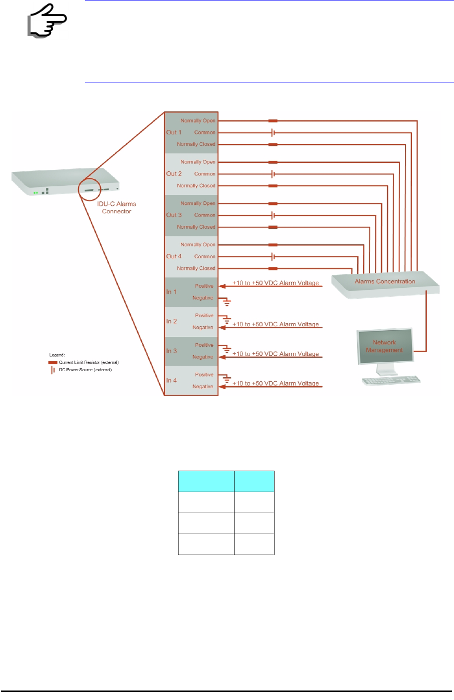
IDU-C Alarm Connector
The IDU-C Alarm interface is a 25 pin D type female connector. Its pinout is
listed in table B-3.
The following diagram describes how to connect external input and output
alarms.
Table B-3: IDU-C Alarm Connector (Dry-Contact)
I/O Description Pin
Input 1 Positive 14
Input 1 Negative 15
Input 2 Positive 16
Input 2 Negative 17
Input 3 Positive 18
Input 3 Negative 19
Input 4 Positive 20
Input 4 Negative 21
Output 1 Normally Open 1
Output 1 Common 2
Output 1 Normally
Closed
3
Output 2 Normally Open 4
Output 2 Common 5
Output 2 Normally
Closed
6
Output 3 Normally Open 7
Output 3 Common 8
Output 3 Normally
Closed
9
Output 4 Normally Open 10
Output 4 Common 11
Output 4 Normally
Closed
12
IDU-C Alarm Connector Appendix B
RADWIN 1000/2000 User Manual Version 2.5p-4 B-4
Figure B-1: Example for connecting the alarm connector
DC Power Terminal
Note
• Use an external current limit resistor to limit the current at the output
relays to 1 Ampere. Such resistor is not required if the equipment
connected to the IDU supports current limiting to 1 Amp.
• The voltage of the input alarm must be within the range of -10 to -50
VDC.
Table B-4: Terminal Block 3-pin -48VDC
Function Pin
+Right
Chassis Center
–Left
RADWIN 1000/2000 User Manual Version 2.5p-4 C-1
Appendix C
Pole and Wall Installation
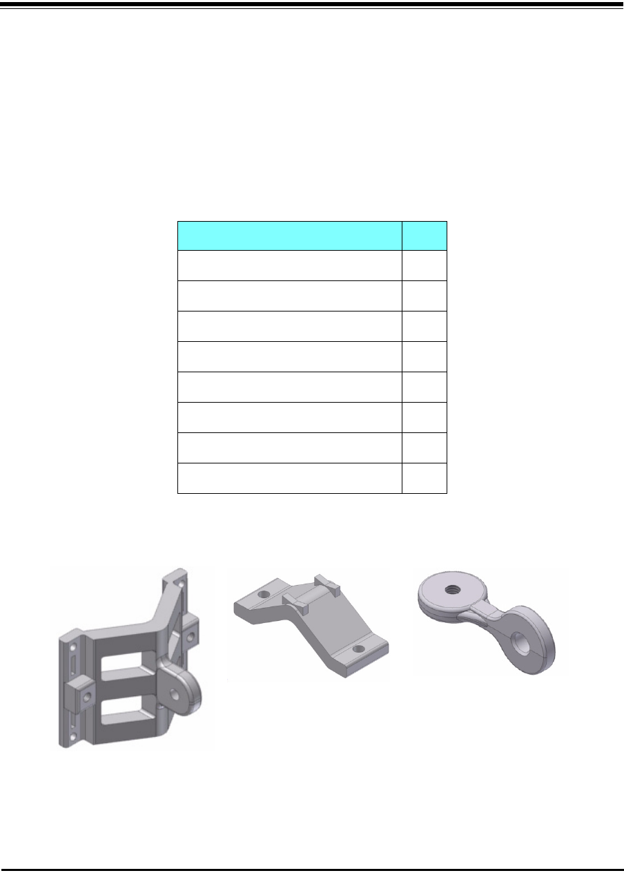
ODU Mounting Kit Contents
Table C-1: Bill of Materials: ODU mounting kit
Item Qty
Large Clamp (see figure C-1)1
Small Clamp (see figure C-2)1
Arm (see figure C-3)1
Screw hex head M8x40 4
Screw hex head M8x70 2
Washer flat M8 4
Washer spring M8 3
M8 Nuts 2
Figure C-1: Large Clamp Figure C-2: Small Clamp Figure C-3: Arm
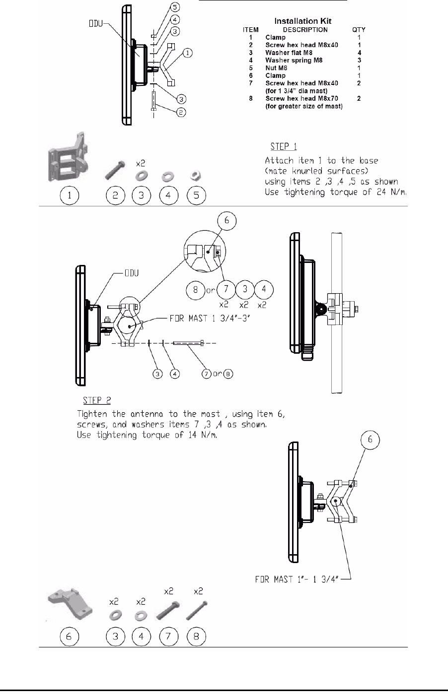
Mounting RADWIN 1000/2000 on a pole Appendix C
RADWIN 1000/2000 User Manual Version 2.5p-4 C-2
Mounting RADWIN 1000/2000 on a pole
Figure C-4: Mounting on a pole
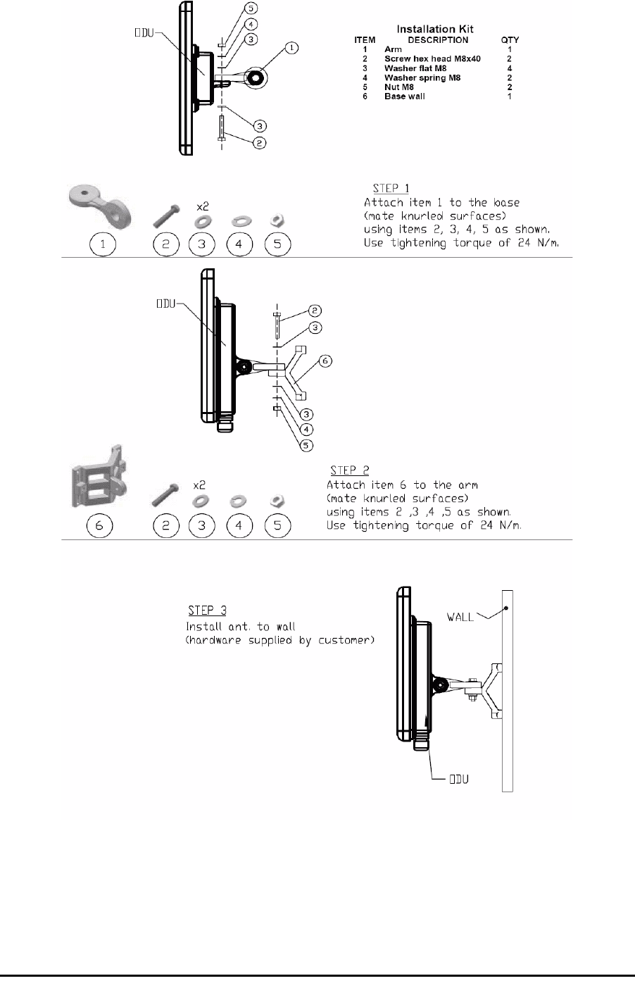
Mounting RADWIN 1000/2000 on a Wall Appendix C
RADWIN 1000/2000 User Manual Version 2.5p-4 C-3
Mounting RADWIN 1000/2000 on a Wall
Figure C-5: Mounting on a Wall
Mounting an External Antenna
Optional external antennas can be mounted on a pole. The external mount-
ing kit varies according to the specific antenna.

RADWIN 1000/2000 User Manual Version 2.5p-4 D-1
Appendix D
Link Budget Calculator
Overview
The Link Budget Calculator is a utility for calculating the expected perfor-
mance of the RADWIN 1000/2000 wireless link and the possible configura-
tions for a specific link range.
The utility allows you to calculate the expected RSS of the link, and find the
type of services and their effective throughput as a function of the link
range and deployment conditions.
User Input
You are required to enter or choose the following parameters. Depending
on the product, some of the parameters have a default value that cannot be
changed.
• Product (or Regulation and Band)
• Channel Bandwidth (fixed to 20 MHz for RADWIN 1000/2000)
• Tx Power (maximum Tx power per modulation is validated)
• Antenna Type (cannot be changed for ODU with integrated antenna)
• Antenna Gain per site (cannot be changed for integrated antenna)
• Cable Loss per site (cannot be changed for integrated antenna)
• Required Fade Margin
• Rate (and Adaptive check box)
• Service Type (Ethernet Only for RADWIN 1000/2000 version 2.1)
• Required Range
Link Budget Calculator Internal Data
For each product (or Regulation and Band) the calculator stores the follow-
ing data required for link budget calculations:
• Maximum Transmit power (per modulation)
• Receiver Sensitivity (per modulation) for Ethernet service and for
TDM services at various BER
• Maximum linear input power (used to calculate minimum distance)

Calculations Appendix D
RADWIN 1000/2000 User Manual Version 2.5p-4 D-2
• Antenna gain and cable loss for ODU with integrated antenna
• Available Channel Bandwidths
Calculations
EIRP
Expected RSS and Fade Margin
where:
Site A is the transmitting site
Site B is the receiving site
PathLoss is calculated according to the free space model,
where Sensitivity is dependent on air-rate.
Min and Max Range
MinRange is the shortest range for which
per air-rate.
MaxRange (with Adaptive checked) is the largest range for which
, at the highest air-rate for which this relation-
ship is true. In a link with adaptive rate this will be the actual behavior.
MaxRange (for a given air-rate) is the largest range for which
.
Service
The Ethernet throughput is calculated according to internal product algo-
rithms.
Availability
The Service Availability calculation is based on the Vigants Barnett method
which predicts the downtime probability based on a climate factor (C fac-
tor).
EIRP TxPower AntennaGainSiteA CableLossSiteA
–+=
ExpectedRSS EIRP PathLoss AntennaGainSiteB CableLossSiteB
–+–=
PathLoss 32.45 20 frequencyMHz
()20 RequiredRangeKm
()
10
log×+
10
log×+=
ExpectedFadeM inarg Sensitivity ExpectedRSS–=
ExpectedRSS MaxInputPower≤
ExpectedRSS Sensitivity≥
ExpectedRSS Sensitivity RequiredFadeM inarg+≥

Antenna Height Appendix D
RADWIN 1000/2000 User Manual Version 2.5p-4 D-3
Antenna Height
The recommended antenna height required for line of sight is calculated as
the sum the Fresnel zone height and the boresight height. See About the
Fresnel Zone below.
The Fresnel zone height is calculated as:
The boresight clearance height is calculated as:
where .
Running the Link Budget Calculator
The Link Budget Calculator is supplied on the RADWIN Manager CD. It may
be run stand-alone from the CD or from the RADWIN Manager application.
¾To run the Link Budget Calculator from the CD:
1. Insert the RADWIN Manager CD into the drive on the managing com-
puter. In the window which opens, click the Link Budget Calculator
option.
2. If the CD autorun application does not start by itself, then point your
browser to
Z:\RADWIN\Setup\DATA\Link Budget Calculator.htm
where Z should be replaced with your own CD drive name.
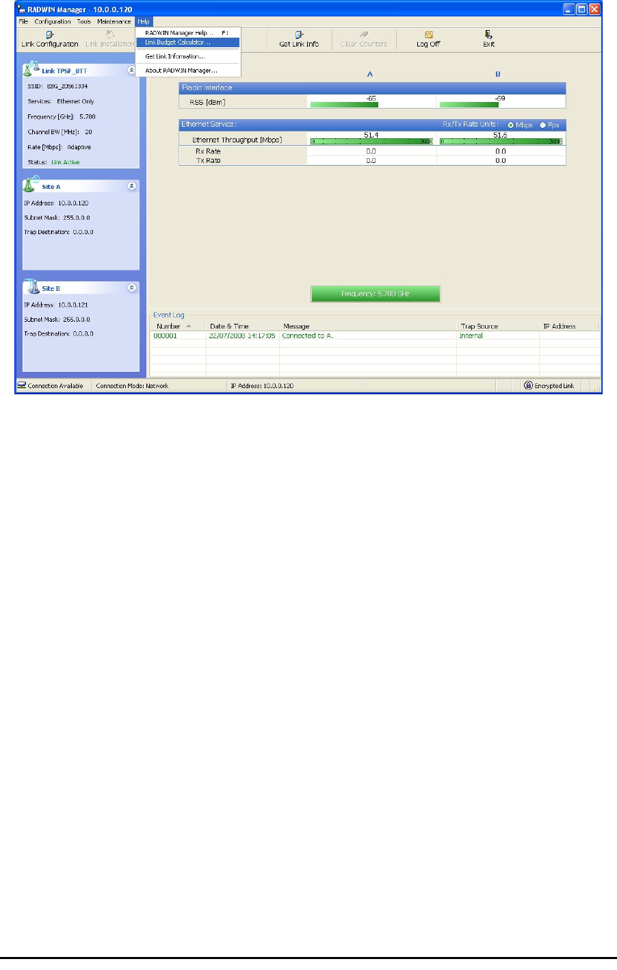
¾To run the Link Budget Calculator from the RADWIN Manager:
•Choose Help | Link Budget Calculator from the main menu of the
RADWIN Manager as in the following figure:
Availability 610
7–
×Cfactor×frequencyGHz
×RequiredRangeKM
()
3
×
10
ExpectedFadeM inarg–
10
------------------------------------------------------------
×
=
0.6
300
frequencyGHz
----------------------------------- ExpectedRange
2
-----------------------------------------
2
×
ExpectedRange
2
----------------------------------------- ExpectedRange
2
-----------------------------------------
+
--------------------------------------------------------------------------------------------×
R2Maean ExpectedRange
2
-----------------------------------------
2
+RMaean
–
RMean 6367.4425Km=
Running the Link Budget Calculator Appendix D
RADWIN 1000/2000 User Manual Version 2.5p-4 D-4
Figure D-1: Accessing the Link Budget Calculator
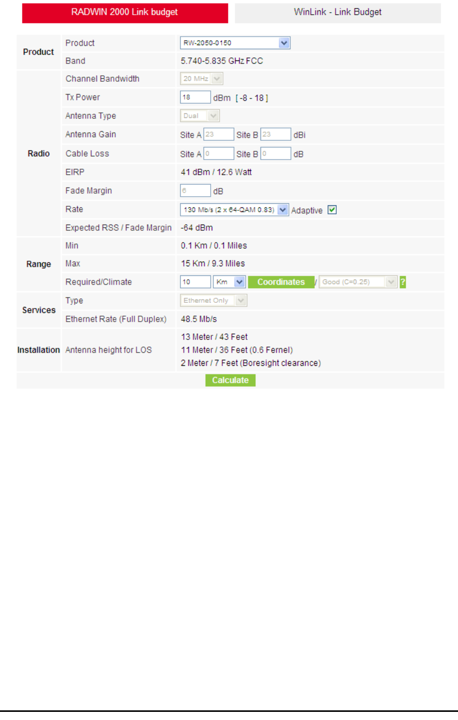
However invoked, your browser displays the following page:
Running the Link Budget Calculator Appendix D
RADWIN 1000/2000 User Manual Version 2.5p-4 D-5
Figure D-2: Link Budget Screen
Running the Link Budget Calculator Appendix D
RADWIN 1000/2000 User Manual Version 2.5p-4 D-6
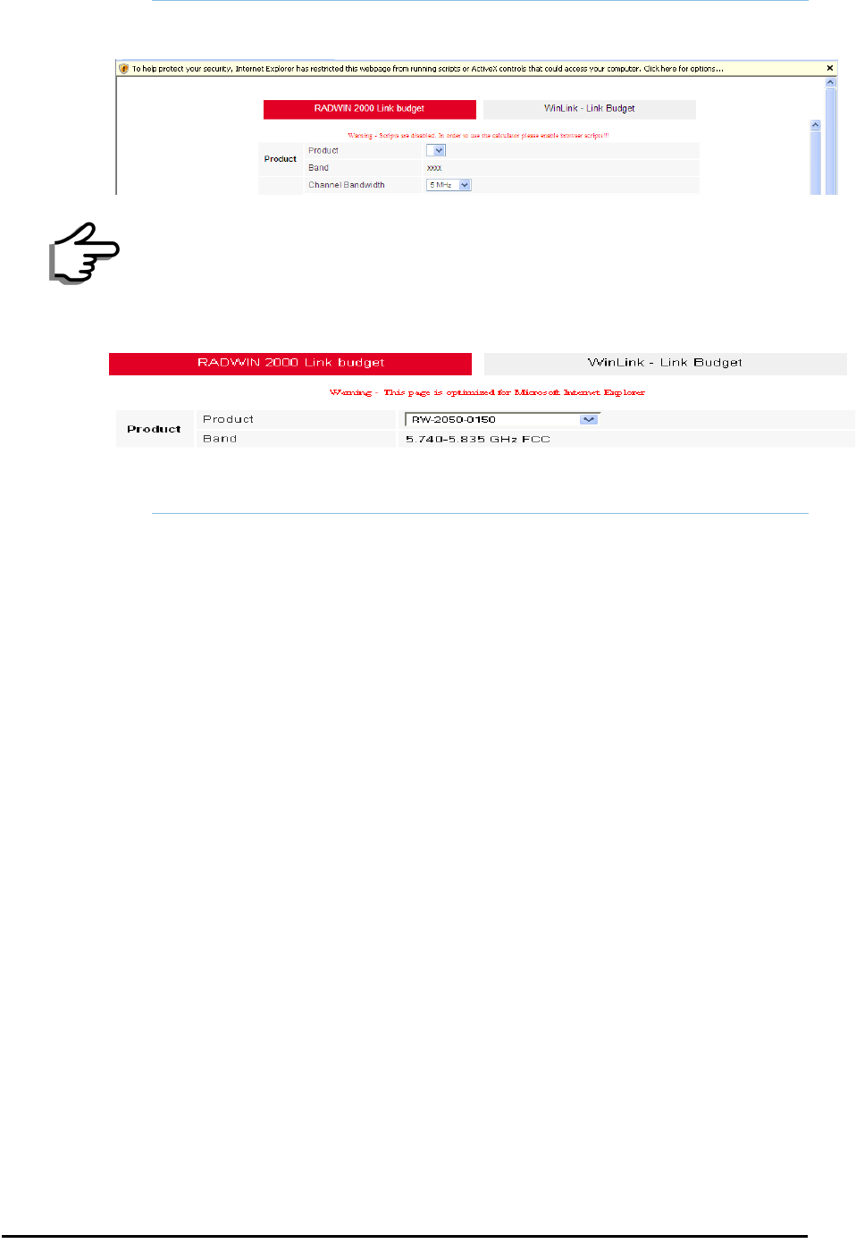
¾To use the Link Budget Calculator for RADWIN 1000/2000:
1. Choose a product from the drop-down list (or choose a Regulation and
Band):
Note
• Microsoft Internet Explorer users may see a warning message like
this:
Click the yellow bar and follow the instructions to allow blocked
content.
• Mozilla FireFox and Google Chrome users may see a warning mes-
sage like this:
You may ignore it and continue.
Running the Link Budget Calculator Appendix D
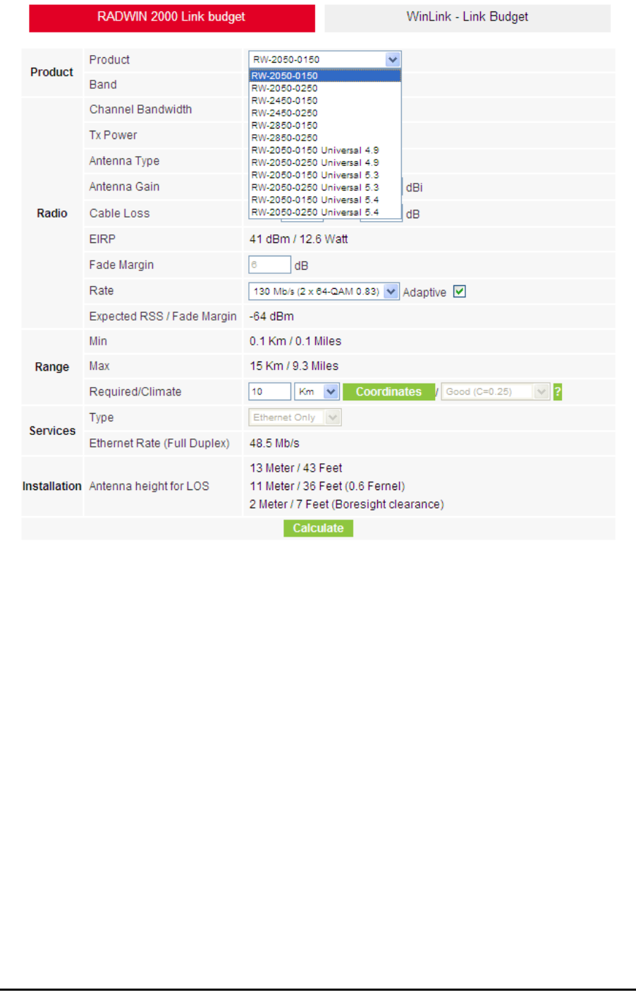
RADWIN 1000/2000 User Manual Version 2.5p-4 D-7
Figure D-3: Product selector
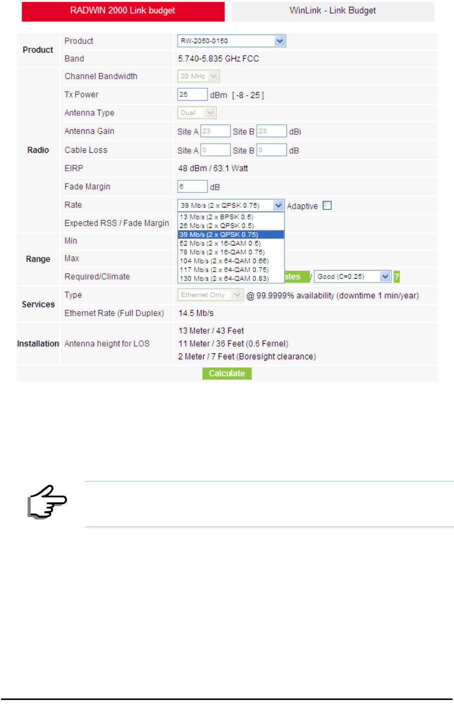
2. Enter the radio details. Note that Rate is chosen from a drop-down list:
Running the Link Budget Calculator Appendix D
RADWIN 1000/2000 User Manual Version 2.5p-4 D-8
Figure D-4: Rate selector
The Rate shown, defines the air-interface rate in Mbps. The system
operates in TDD mode and has the overhead of the air-interface pro-
toco.l Thus, the Ethernet actual throughput is provided by the Ethernet
Rate.
The Fade margin is the minimum required for LOS conditions. For
degraded link conditions, a larger Fade margin should be used.
The EIRP is given in dBm and Watts.
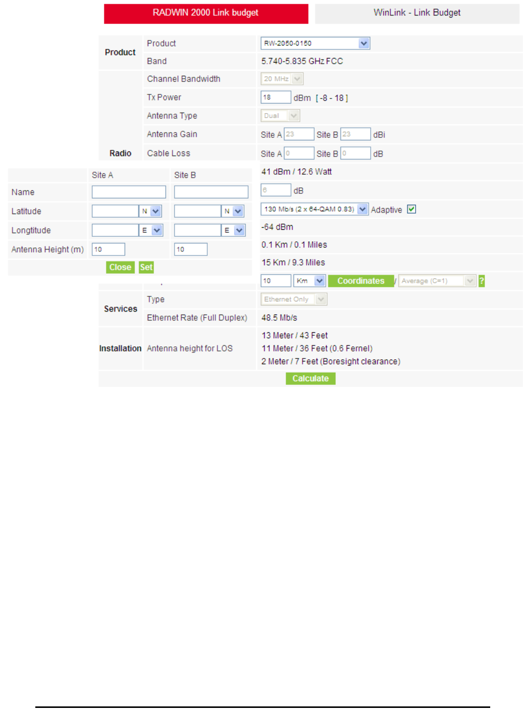
3. If the required range between the two link sites is known, you may enter
it directly. Alternatively, you may enter the latitude and longitude of each
site in the link, in which case the distance between them will be calcu-
lated and displayed.
Note
For a given air-rate, Ethernet throughput will decrease with increasing range
due to propagation delay.
Running the Link Budget Calculator Appendix D
RADWIN 1000/2000 User Manual Version 2.5p-4 D-9
Figure D-5: Calculation of distance from site coordinates
Running the Link Budget Calculator Appendix D
RADWIN 1000/2000 User Manual Version 2.5p-4 D-10
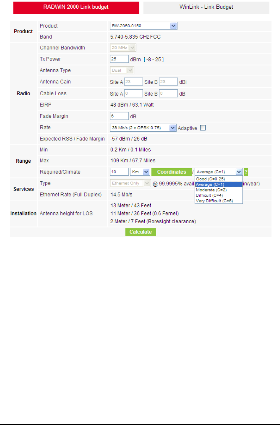
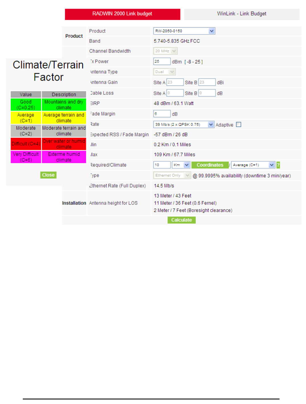
4. Located to the right of the green Coordinates button is a dropdown list of
Climactic C Factor values.
Figure D-6: Climactic C Factors
For help about what these mean, click the ? button to the right of the list
in figure D-6.

Running the Link Budget Calculator Appendix D
RADWIN 1000/2000 User Manual Version 2.5p-4 D-12
Figure D-8: World map showing C Factor contours
5. Click Calculate to obtain the required performance estimate.
The Expected Performance parameters are calculated and displayed:
•Expected RSS - the expected RSS that the RADWIN Manager
shows when the RADWIN 1000/2000 ODUs are optimally aligned
•Ethernet Rate - maximum throughput available for the chosen
parameter combination
•Antenna height for LOS – the minimum antenna height required
for line-of-sight operation. It is the sum of the height required for
boresight clearance due to the earth’s curvature plus the height
required to clear the Fresnel zone
If the expected performance is not suitable for your application, try different
parameters and repeat the calculation.
Note
Placing the cursor in any other calculated field will also update the
calculated results.
About the Fresnel Zone Appendix D
RADWIN 1000/2000 User Manual Version 2.5p-4 D-13
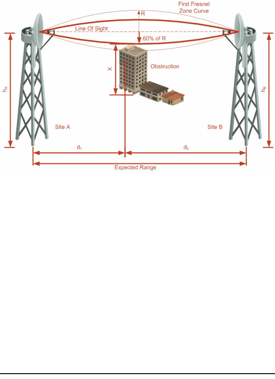
About the Fresnel Zone
The Fresnel zone (pronounced "frA-nel", with a silent “s”) is an elliptically
shaped conical zone of electromagnetic energy that propagates from the
transmitting antenna to the receiving antenna. It is always widest in the
middle of the path between the two antennas.
Figure D-9: Fresnel zone
Fresnel loss is the path loss occurring from multi-path reflections from
reflective surfaces such as water, and intervening obstacles such as build-
ings or mountain peaks within the Fresnel zone.
Radio links should be designed to accommodate obstructions and atmo-
spheric conditions, weather conditions, large bodies of water, and other
reflectors and absorbers of electromagnetic energy.
The Fresnel zone provides us with a way to calculate the amount of clear-
ance that a wireless wave needs from an obstacle to ensure that the obsta-
cle does not attenuate the signal.
There are infinitely many Fresnel zones located coaxially around the center
of the direct wave. The outer boundary of the first Fresnel zone is defined
as the combined path length of all paths, which are half wavelength (1/2 λ)
of the frequency transmitted longer than the direct path. If the total path
distance is one wavelength (1 λ) longer than the direct path, then the outer
boundary is said to be two Fresnel zones. Odd number Fresnel zones rein-
force the direct wave path signal; even number Fresnel zones cancel the
direct wave path signal.

About the Fresnel Zone Appendix D
RADWIN 1000/2000 User Manual Version 2.5p-4 D-14
The amount of the Fresnel zone clearance is determined by the wavelength
of the signal, the path length, and the distance to the obstacle. For reliabil-
ity, point-to-point links are designed to have at least 60% of the first Fresnel
zone clear to avoid significant attenuation.
The concept of the Fresnel zone is shown in figure D-9 above. The top of
the obstruction does not extend far into the Fresnel zone, leaving 60% of
the Fresnel zone clear; therefore, the signal is not significantly attenuated.
For more about Fresnel zone, see http://en.wikipedia.org/wiki/
Fresnel_zone.

RADWIN 1000/2000 User Manual Version 2.5p-4 E-1
Appendix E
Lightning Protection and
Grounding Guidelines
Meticulous implementation of the guidelines in this appendix will provide
best protection against electric shock and lightning.
The RADWIN 1000/2000™ Lightning protection system consists of the fol-
lowing components:
• Grounding for the antenna coax cable
• Grounding for each IDU and ODU
• External Primary Surge Suppressor units and grounding for the out-
door cable
• Internal ESD protection circuits over the Power/Telecom lines
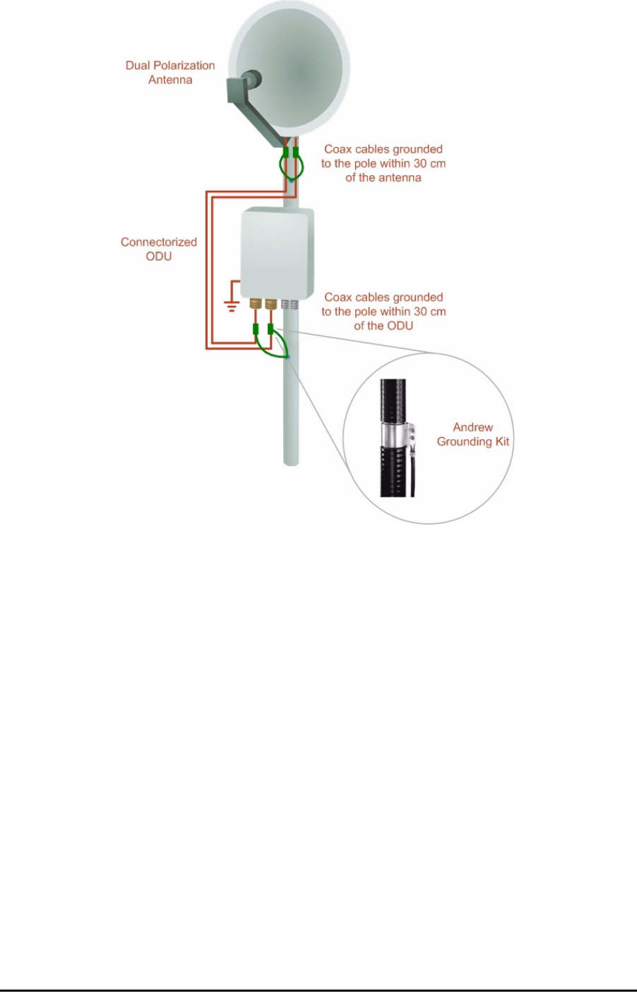
Grounding for Antenna Cable
A Grounding Kit must be connected to the coax antenna cable and reliably
grounded as shown in Figure X. The grounding kit is an Andrew Type
223158-2 (www.andrew.com). See figure E-1 below.
Warning
100% protection is neither implied nor possible.
Note
This appendix is at best a guide. The actual degree of lightning protection
required depends on local conditions and regulations.
Grounding for Indoor/Outdoor Units Appendix E
RADWIN 1000/2000 User Manual Version 2.5p-4 E-2
Figure E-1: Grounding antenna cables
Grounding for Indoor/Outdoor Units
ODU Grounding
RADWIN 1000/2000™ uses a Shielded CAT-5e cable to interconnect the
Outdoor (ODU) and Indoor (IDU) units.
However, this shielding does not provide a good Lightning Discharge path,
since it can not tolerate the high Lightning Current surges.
To provide an alternate Lightning Discharge path, the ODU and antenna
grounding posts should be connected to ground point by a 10 AWG short
copper wire.
The device should be permanently connected to ground.
IDU Grounding
The IDUs grounding post should be connected to the internal ground point,
using a grounding wire of at least 10 AWG. The grounding wire should be
connected to a grounding rod or the building grounding system.
External Lightning Surge Suppressors and Grounding Appendix E
RADWIN 1000/2000 User Manual Version 2.5p-4 E-3
The device should be permanently connected to ground.
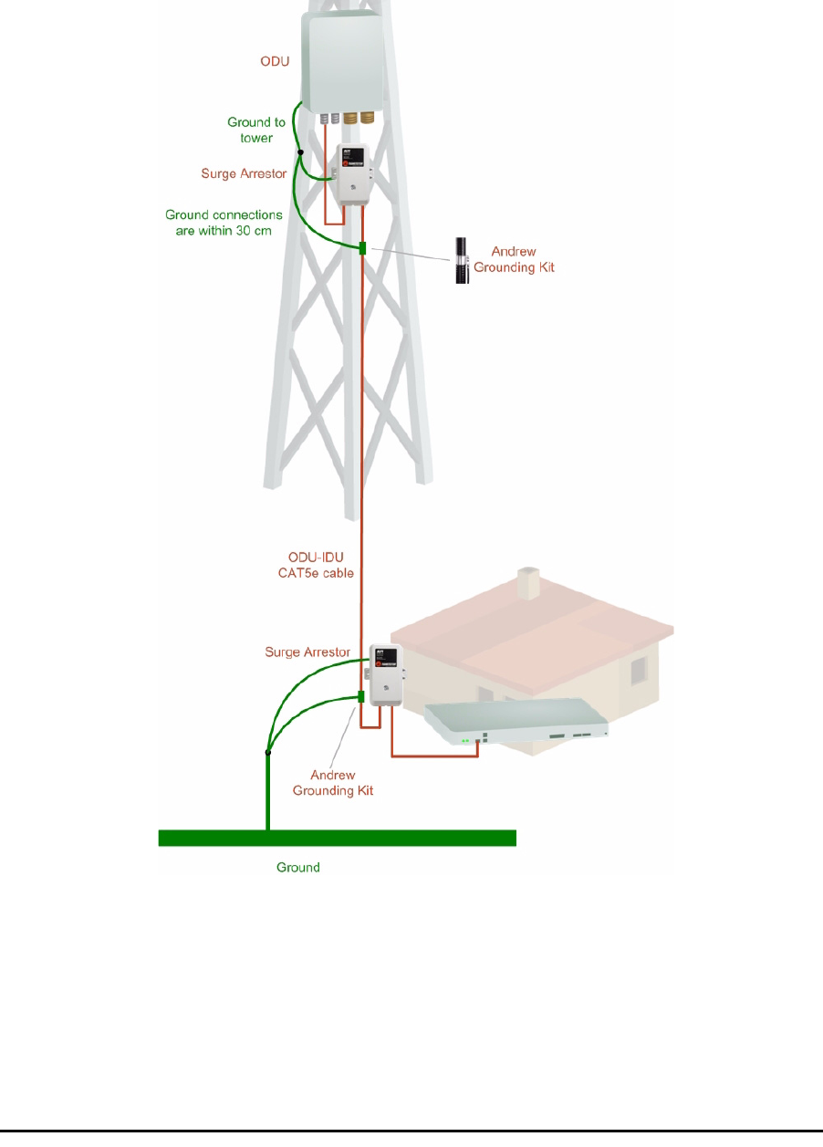
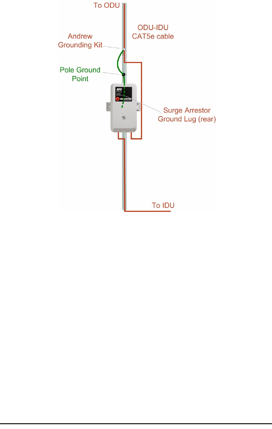
External Lightning Surge Suppressors and Grounding
A Grounding Kit and Surge Arrestor Unit must be located near the ODU and
properly grounded as illustrated in figure E-2 and figure E-3 below:
Figure E-2: Grounding a typical pole installation
External Lightning Surge Suppressors and Grounding Appendix E
RADWIN 1000/2000 User Manual Version 2.5p-4 E-4
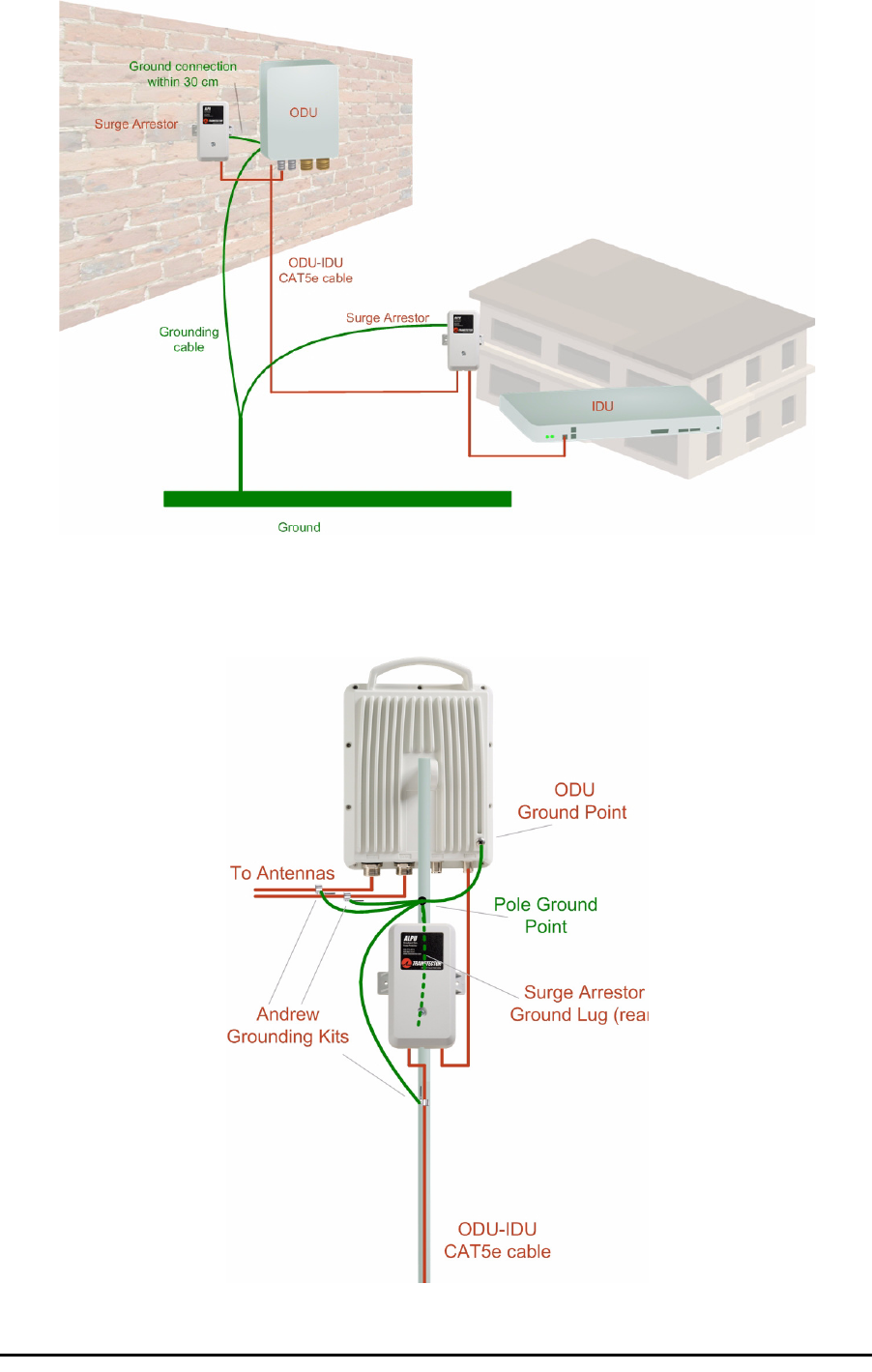
Figure E-3: Grounding a typical wall installation
The next figure shows a close-up of the rear of grounded ODU:
Figure E-4: ODU Surge Suppressor and grounding
External Lightning Surge Suppressors and Grounding Appendix E
RADWIN 1000/2000 User Manual Version 2.5p-4 E-5
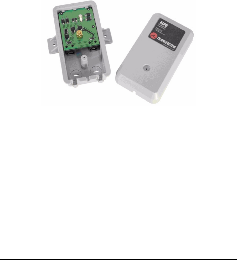
The Transtector protection circuits shown in figure E-5 below, utilize silicon
avalanche diode technology. The unit consists of an outdoor rated NEMA 3R
type enclosure with easy mounting flanges, ground stud attachment and
easy wiring.
The ALPU-POE features RJ-45 protection circuits for the ODU-IDU data pairs
(pins 1,2 & 3,6) and DC power (pins 4,5 & 6,7 with the pairs bonded).
The unit is designed to be wall mounted. An optional set of bracket is avail-
able to allow a wide range of pole mount applications. A dedicated ground
stud is provided inside the unit that must be bonded to the nearest ground-
ing system (or Master Ground bar) for proper surge protection.
The system wiring is installed with RJ-45 type connectors that can feed
directly into the chassis without having to cut, splice or route through awk-
ward strain relief holes.
Figure E-5: Transtector’s Surge Suppressor
¾To mount the lightning protection devices:
1. Mount the device as close to the ODU as possible. Mount the unit so that
the cable connectors are at the bottom (to prevent water from penetrat-
ing), with the strain reliefs facing the ground.
2. Remove the cover by unscrewing the front of the unit.
3. Mount the unit to an outside surface using the two mounting holes.
4. Connect the ODU-IDU cable using the RJ-45 jack.
5. Connect one cable between the ODU and the suppressor using an RJ-45
jack.
6. Connect the suppressor’s ground stud to a grounding point. Use the
appropriate wire gauge and type, keeping the wire as short as possible,
less than 1m (3’), between the stud and the site grounding point.

External Lightning Surge Suppressors and Grounding Appendix E
RADWIN 1000/2000 User Manual Version 2.5p-4 E-6
7. Replace the cover.
A second Surge Arrestor Unit should be mounted at the building entry point
and must be grounded, as shown in figure E-3 above.
¾To mount the lightning protection at the building entry point:
1. Mount the device outside the building, located as near as possible to the
entrance of the CAT-5e ODU-IDU cable. Mount the unit so that the cable
connectors are at the bottom (to prevent water from penetrating), with
the strain reliefs facing the ground.
2. Remove the cover by unscrewing the front of the unit.
3. Mount the unit to an outside surface using the two mounting holes.
4. Connect the ODU-IDU cable using the RJ-45 jack.
5. Connect one cable between the IDU and the suppressor using an RJ-45
jack.
6. Connect the suppressor’s ground stud to a grounding point. Use the
appropriate wire gauge and type, keeping the wire as short as possible,
less than 1m (3’), between the stud and the site grounding point.
7. Replace the cover
Note
There may also be regulatory requirements to cross bond the ODU-IDU CAT-
5e cable at regular intervals up the mast. This may be as frequent as every
10 meters (33 feet).
Internal ESD Protection circuits Appendix E
RADWIN 1000/2000 User Manual Version 2.5p-4 E-7
Figure E-6: Surge Suppressor and grounding at building entry point
Internal ESD Protection circuits
RADWIN 1000/2000™ is designed to meet the ETSI/FCC/Aus/NZ/CSA EMC
and Safety requirements. To fulfill these requirements, the system's Tele-
com lines at the ODU/IDU are Transformer-isolated and include internal ESD
(Electro-Static-Discharge) Protection circuits.

RADWIN 1000/2000 User Manual Version 2.5p-4 F-1
Appendix F
MIB Reference
Introduction
About the MIB
The RADWIN MIB is a set of APIs that enables external applications to con-
trol RADWIN equipment.
The MIB is divided into public and a private API groups:
•Public: RFC-1213 (MIB II) variables, RFC-1214 (MIB II) System and
Interfaces sections
•Private: Controlled by RADWIN and supplements the public group.
This appendix describes the public and private MIB used by RADWIN.
Terminology
The following terms are used in this appendix.
In addition, the MIB uses internally, the older notions of Local site and
Remote site where this manual would use site A and site B.
To avoid burdening the reader, this appendix will follow the MIB usage.
Interface API
Control Method
The RADWIN Manager application provides all the means to configure and
monitor a RADWIN 1000/2000 link, communicating with the SNMP agent in
each ODU. Each SNMP agent contains data on each of the IDUs and ODUs
Term Meaning
MIB Management Information Base
API Application Programming Interface
SNMP Simple Network Management Protocol

Community String Appendix F
RADWIN 1000/2000 User Manual Version 2.5p-4 F-2
in the link. Both agents communicate with each other over the air using a
proprietary protocol.
To control and configure the device using the MIB, you should adhere to the
following rules:
• The connection for control and configuration is to the local site, over
any SNMP/UDP/IP network.
• All Parameters should be consistent between both of the ODUs. Note
that inconsistency of air parameters can break the air connection. To
correct air parameters inconsistency you must reconfigure each of
the ODUs.
• Common practice is to configure the remote site first and then to
configure the local site.
• For some of the configuration parameters additional action must be
taken before the new value is loaded. Please refer to the operation
in the parameters description.
• Some of the MIB parameters values are product dependent. It is
strongly recommend using the RADWIN Manager Application for
changing these values. Setting wrong values may cause indetermi-
nate results.
Community String
To control a link, all SNMP requests should go to the local site IP address.
The RADWIN Manager uses the Read Community strings
public
for the
local ODU and
public-remote
for the remote ODU. It uses Write Commu-
nity strings
netman
for the local ODU and
netman-remote
for the
remote ODU. These are the factory defaults.
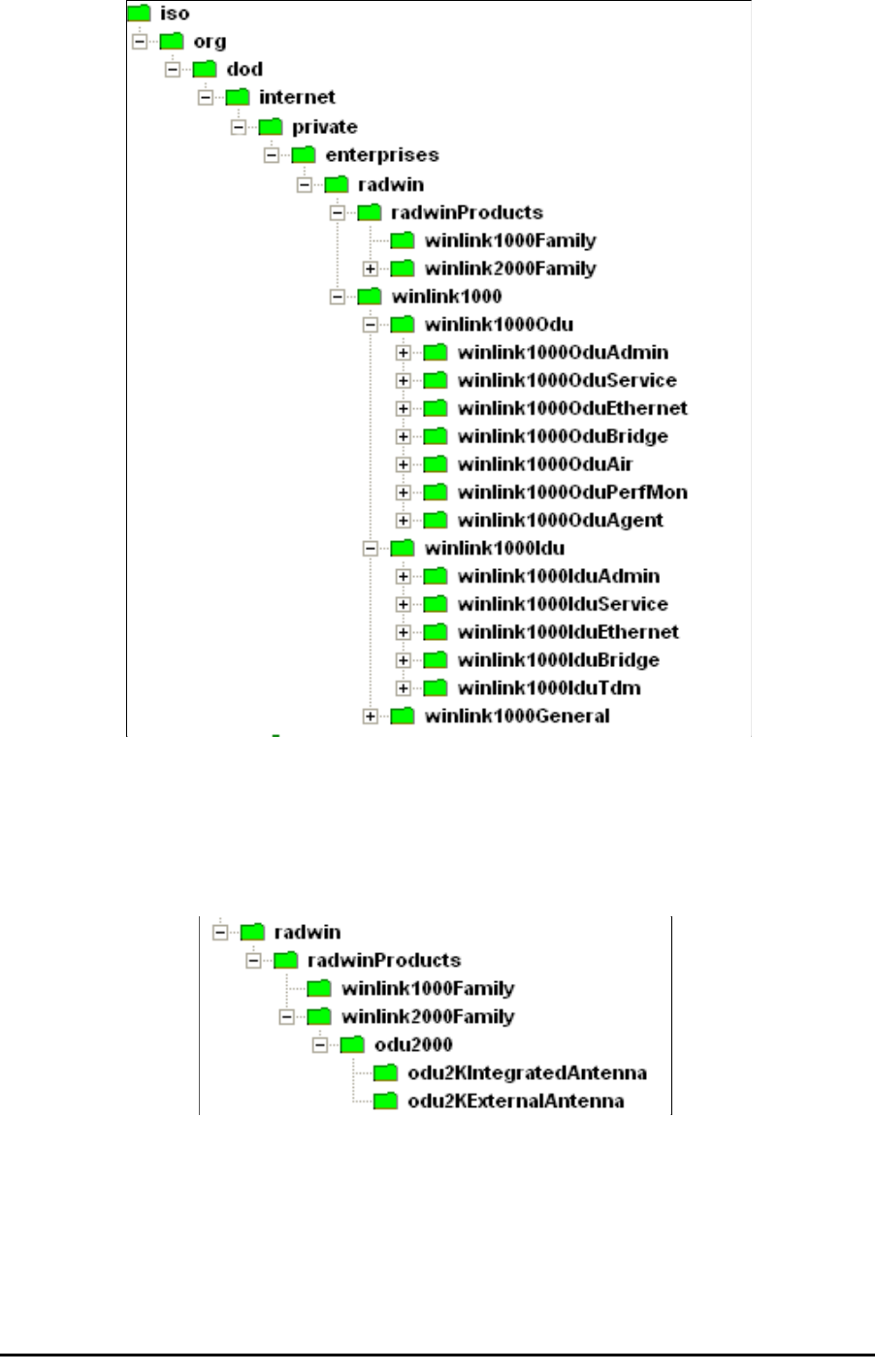
Private MIB Structure
The sections in the private RADWIN MIB and its location in the MIB tree are
shown in figure F-1 below:
Note
Each ODU has a single MAC address and a single IP address.
Private MIB Structure Appendix F
RADWIN 1000/2000 User Manual Version 2.5p-4 F-3
Figure F-1: Top Level Sections of the private MIB
The products MIB section contains the definition of the Object IDs for the
two form factors of the ODU, Integrated Antenna and Connectorized
(referred in the MIB as external antenna):
The ODU MIB contains the sections: Admin, Service, Ethernet, Bridge, Air,
PerfMon and Agent.
The IDU MIB contains the sections: Admin, Service, Ethernet, Bridge and
TDM.
The general MIB include a single generic parameter that is used by all traps
as a trap description parameter.

MIB Parameters Appendix F
RADWIN 1000/2000 User Manual Version 2.5p-4 F-4
MIB Parameters
The following section describes all of the MIB parameters. The MIB parame-
ters follow the following naming convention:
<winlink1000><Section 1>...<Section n><Parameter Name>
For each of the configuration and control parameters (parameters with
read-write access), the “Description” column describes when the new value
is effective. It is recommended that you perform the appropriate action to
make the values affective immediately after any change. Where a change is
required on both sides of the link, it is recommended that you change both
sides of the link first and then perform the action.
Supported Variables from the RFC 1213 MIB
Table F-1: Supported RFC 1213 Variables (Sheet 1 of 2)
Name OID Type
Access
Description
ifIndex .1.3.6.1.2.1.2.2.1.1.xaInteger RO A unique value for each interface.Its value ranges
between 1 and the value of ifNumber.The value for
each interface must remain constant at least from
one re-initialization of the entity's network
management system to the next re-initialization.
ifDescr .1.3.6.1.2.1.2.2.1.2 DisplayString RO A textual string containing information about the
interface.This string should include the name of
the manufacturer, the product name and the
version of the hardware interface.
ifType .1.3.6.1.2.1.2.2.1.3 Integer RO The type of interface, distinguished according to
the physical/link protocol(s) immediately `below'
the network layer in the protocol stack.
ifSpeed .1.3.6.1.2.1.2.2.1.5 Gauge RO An estimate of the interface's current bandwidth in
bits per second.For interfaces which do not vary in
bandwidth or for those where no accurate
estimation can be made, this object should ontain
the nominal bandwidth.
ifPhysAddress .1.3.6.1.2.1.2.2.1.6 Phys-Address RO The interface's address at the protocol layer
immediately `below' the network layer in the
protocol stack. For interfaces which do not have
such an address (e.g., a serial line), this object
should contain an octet string of zero length.
ifAdminStatus .1.3.6.1.2.1.2.2.1.7 Integer RW The desired state of the interface. The testing(3)
state indicates that no operational packets can be
passed.
ifOperStatus .1.3.6.1.2.1.2.2.1.8 Integer RO The current operational state of the interface. The
testing(3) state indicates that no operational
packets can be passed.
ifInOctets .1.3.6.1.2.1.2.2.1.10.x Counter RO The total number of octets received on the
interface, including framing characters.
ifInUcastPkts .1.3.6.1.2.1.2.2.1.11.x Counter RO The number of subnetwork-unicast packets
delivered to a higher-layer protocol.
ifInNUcastPkts .1.3.6.1.2.1.2.2.1.12.x Counter RO The number of non-unicast (i.e., subnetwork-
broadcast or subnetwork-multicast) packets
delivered to a higher-layer protocol.

MIB Parameters Appendix F
RADWIN 1000/2000 User Manual Version 2.5p-4 F-5
MIB Parameters
ifInErrors .1.3.6.1.2.1.2.2.1.14.x Counter RO The number of inbound packets that contained
errors preventing them from being deliverable to a
higher-layer protocol.
ifOutOctets .1.3.6.1.2.1.2.2.1.16.x Counter RO The total number of octets transmitted out of the
interface, including framing characters.
ifOutUcastPkts .1.3.6.1.2.1.2.2.1.17.x Counter RO The total number of packets that higher-level
protocols requested be transmitted to a
subnetwork-unicast address, including those that
were discarded or not sent.
ifOutNUcastPkts .1.3.6.1.2.1.2.2.1.18.x Counter RO The total number of packets that higher-level
protocols requested be transmitted to a non-
unicast (i.e., a subnetwork-broadcast or
subnetwork-multicast) address, including those
that were discarded or not sent.
a. x is the interface ID
Table F-2: Private MIB Parameters (Sheet 1 of 14)
Name OID Type
Access
Description
winlink1000OduAdmProductType 1.3.6.1.4.1.4458.1000.1.1.1 DisplayString RO ODU configuration description.
winlink1000OduAdmHwRev 1.3.6.1.4.1.4458.1000.1.1.2 DisplayString RO ODU Hardware Version.
winlink1000OduAdmSwRev 1.3.6.1.4.1.4458.1000.1.1.3 DisplayString RO ODU Software Version.
winlink1000OduAdmLinkName 1.3.6.1.4.1.4458.1000.1.1.4 DisplayString RW Link Name. A change is effective immediately.
winlink1000OduAdmResetCmd 1.3.6.1.4.1.4458.1000.1.1.5 Integer RW Reset Command. A set command with a value of 3
will cause a device reset. The read value is always
0.
winlink1000OduAdmAddres 1.3.6.1.4.1.4458.1000.1.1.6 IpAddress RW ODU IP address. A change is effective after reset.
The parameter is kept for backward compatibility.
Using the alternative parameter:
winlink1000OduAdmIpParamsCnfg is
recommended.
winlink1000OduAdmMask 1.3.6.1.4.1.4458.1000.1.1.7 IpAddress RW ODU Subnet Mask. A change is effective after
reset. The parameter is kept for backward
compatibility. Using the alternative parameter:
winlink1000OduAdmIpParamsCnfg is
recommended.
winlink1000OduAdmGateway 1.3.6.1.4.1.4458.1000.1.1.8 IpAddress RW ODU default gateway. A change is effective after
reset. The parameter is kept for backward
compatibility. Using the alternative parameter:
winlink1000OduAdmIpParamsCnfg is
recommended.
winlink1000OduAdmBroadcast 1.3.6.1.4.1.4458.1000.1.1.10 Integer RW This parameter is reserved for the Manager
application provided with the product.
winlink1000OduAdmHostsTable N/A Trap destinations table. Each trap destination is
defined by an IP address and a UDP port. Up to 10
addresses can be configured.
winlink1000OduAdmHostsEntry N/A Trap destinations table entry.
winlink1000OduAdmHostsIndex RO Trap destinations table index.
winlink1000OduAdmHostsIp 1.3.6.1.4.1.4458.1000.1.1.12.1.2 IpAddress RW Trap destination IP address. A change is effective
immediately.
Table F-1: Supported RFC 1213 Variables (Sheet 2 of 2)
Name OID Type
Access
Description

MIB Parameters Appendix F
RADWIN 1000/2000 User Manual Version 2.5p-4 F-6
winlink1000OduAdmHostsPort 1.3.6.1.4.1.4458.1000.1.1.12.1.3 Integer RW UDP port of the trap destination. A change is
effective immediately.
winlink1000OduBuzzerAdminState 1.3.6.1.4.1.4458.1000.1.1.13 Integer RW This parameter controls the activation of the
buzzer while the unit is in install mode. A change is
effective immediately. The valid values are:
disabled (0) enabled (1).
winlink1000OduProductId 1.3.6.1.4.1.4458.1000.1.1.14 DisplayString RO This parameter is reserved for the Manager
application provided with the product.
winlink1000OduReadCommunity 1.3.6.1.4.1.4458.1000.1.1.15 DisplayString RW Read Community String. This parameter always
returns ***** when retrieving its value. It is used by
the Manager application to change the Read
Community String. The SNMP agent accepts only
encrypted values.
winlink1000OduReadWriteCommunity 1.3.6.1.4.1.4458.1000.1.1.16 DisplayString RW Read/Write Community String. This parameter
always returns ***** when retrieving its value. It is
used by the Manager application to change the
Read/Write Community String. The SNMP agent
accepts only encrypted values.
winlink1000OduTrapCommunity 1.3.6.1.4.1.4458.1000.1.1.17 DisplayString RW Trap Community String. This parameter is used by
the Manager application to change the Trap
Community String. The SNMP agent accepts only
encrypted values.
winlink1000OduAdmSnmpAgentVersion 1.3.6.1.4.1.4458.1000.1.1.18 Integer RO Major version of the SNMP agent.
winlink1000OduAdmRemoteSiteName 1.3.6.1.4.1.4458.1000.1.1.19 DisplayString RO Remote site name. Returns the same value as
sysLocation parameter of the remote site.
winlink1000OduAdmSnmpAgentMinorVe
rsion
1.3.6.1.4.1.4458.1000.1.1.20 Integer RO Minor version of the SNMP agent.
winlink1000OduAdmLinkPassword 1.3.6.1.4.1.4458.1000.1.1.21 DisplayString RW Link Password. This parameter always returns
***** when retrieving its value. It is used by the
Manager application to change the Link Password.
The SNMP agent accepts only encrypted values.
winlink1000OduAdmSiteLinkPassword 1.3.6.1.4.1.4458.1000.1.1.22 DisplayString RW Site Link Password. This parameter always returns
***** when retrieving its value. It is used by the
Manager application to change the Link Password
of the site. The SNMP agent accepts only
encrypted values.
winlink1000OduAdmDefaultPassword 1.3.6.1.4.1.4458.1000.1.1.23 Integer RO This parameter indicates if the current Link
Password is the default password.
winlink1000OduAdmConnectionType 1.3.6.1.4.1.4458.1000.1.1.24 Integer RO This parameter indicates if the Manager
application is connected to the local ODU or to the
remote ODU over the air. A value of 'unknown'
indicates community string mismatch.
winlink1000OduAdmBackToFactorySetti
ngsCmd
1.3.6.1.4.1.4458.1000.1.1.25 Integer RW Back to factory settings Command. A change is
effective after reset. The read value is always 0.
winlink1000OduAdmIpParamsCnfg 1.3.6.1.4.1.4458.1000.1.1.26 DisplayString RW ODU IP address Configuration. The format is:
<IP_Address>|<Subnet_Mask>|<Default_Gatewa
y>|
winlink1000OduAdmVlanID 1.3.6.1.4.1.4458.1000.1.1.27 Integer RW VLAN ID. Valid values are 1 to 4094. Initial value is
0 meaning VLAN unaware.
winlink1000OduAdmVlanPriority 1.3.6.1.4.1.4458.1000.1.1.28 Integer RW VLAN Priority. 0 is lowest priority 7 is highest
priority.
winlink1000OduAdmSN 1.3.6.1.4.1.4458.1000.1.1.29 DisplayString RO IDU Serial Number
winlink1000OduSrvMode 1.3.6.1.4.1.4458.1000.1.2.1 Integer RW System mode. The only value that can be set is
installMode; normalMode reserved to the Manager
application provided with the product. A change is
effective after link re-synchronization.
Table F-2: Private MIB Parameters (Sheet 2 of 14)
Name OID Type
Access
Description

MIB Parameters Appendix F
RADWIN 1000/2000 User Manual Version 2.5p-4 F-7
winlink1000OduSrvBridging 1.3.6.1.4.1.4458.1000.1.2.3 Integer RO Bridging Mode. Valid values are: disabled (0)
enabled (1).
winlink1000OduEthernetRemainingRate 1.3.6.1.4.1.4458.1000.1.3.1 Integer RO Current Ethernet bandwidth in bps.
winlink1000OduEthernetIfTable N/A ODU Ethernet Interface table.
winlink1000OduEthernetIfEntry N/A ODU Ethernet Interface table entry.
winlink1000OduEthernetIfIndex 1.3.6.1.4.1.4458.1000.1.3.2.1.1 Integer RO ODU Ethernet Interface Index.
winlink1000OduEthernetIfAddress 1.3.6.1.4.1.4458.1000.1.3.2.1.5 DisplayString RO ODU MAC address.
winlink1000OduEthernetIfAdminStatus 1.3.6.1.4.1.4458.1000.1.3.2.1.6 Integer RW Required state of the interface.
winlink1000OduEthernetIfOperStatus 1.3.6.1.4.1.4458.1000.1.3.2.1.7 Integer RO Current operational state of the interface.
winlink1000OduEthernetIfFailAction 1.3.6.1.4.1.4458.1000.1.3.2.1.8 Integer RW Failure action of the interface.
winlink1000OduEthernetNumOfPorts 1.3.6.1.4.1.4458.1000.1.3.3 Integer RO Number of ODU network interfaces.
winlink1000OduBridgeBasePortTable N/A ODU Bridge Ports table.
winlink1000OduBridgeBasePortEntry N/A ODU Bridge Ports table entry.
winlink1000OduBridgeBasePortIndex RO ODU Bridge Port Number.
winlink1000OduBridgeBaseIfIndex RO IfIndex corresponding to ODU Bridge port.
winlink1000OduBridgeTpMode 1.3.6.1.4.1.4458.1000.1.4.4.101 Integer RW ODU bridge mode. A change is effective after
reset. Valid values: hubMode (0) bridgeMode (1).
winlink1000OduBridgeTpPortTable N/A ODU Transparent Bridge Ports table.
winlink1000OduBridgeTpPortEntry N/A ODU Transparent Bridge Ports table entry.
winlink1000OduBridgeTpPortIndex RO ODU Transparent Bridge Port Number.
winlink1000OduBridgeTpPortInFrames 1.3.6.1.4.1.4458.1000.1.4.4.3.1.3 Counter RO Number of frames received by this port.
winlink1000OduBridgeTpPortOutFrames 1.3.6.1.4.1.4458.1000.1.4.4.3.1.4 Counter RO Number of frames transmitted by this port.
winlink1000OduBridgeTpPortInBytes 1.3.6.1.4.1.4458.1000.1.4.4.3.1.10
1
Counter RO Number of bytes received by this port.
winlink1000OduBridgeTpPortOutBytes 1.3.6.1.4.1.4458.1000.1.4.4.3.1.10
2
Counter RO Number of bytes transmitted by this port.
winlink1000OduAirFreq 1.3.6.1.4.1.4458.1000.1.5.1 Integer RW Installation Center Frequency. Valid values are
product dependent. A change is effective after link
re-synchronization.
winlink1000OduAirDesiredRate 1.3.6.1.4.1.4458.1000.1.5.2 Integer RW Deprecated parameter actual behavior is read-
only. Required Air Rate. For Channel Bandwidth of
20 10 5 MHz divide the value by 1 2 4 respectively.
winlink1000OduAirSSID 1.3.6.1.4.1.4458.1000.1.5.3 DisplayString RW Reserved for the Manager application provided
with the product.
winlink1000OduAirTxPower 1.3.6.1.4.1.4458.1000.1.5.4 Integer RW Required Transmit power in dBm . This is a
nominal value while the actual transmit power
includes additional attenuation. The min and max
values are product specific. A change is effective
immediately.
winlink1000OduAirSesState 1.3.6.1.4.1.4458.1000.1.5.5 Integer RO Current Link State. The value is active (3) during
normal operation.
winlink1000OduAirMstrSlv 1.3.6.1.4.1.4458.1000.1.5.6 Integer RO This parameter indicates if the device was
automatically selected into the radio link master or
slave. The value is undefined if there is no link.
winlink1000OduAirResync 1.3.6.1.4.1.4458.1000.1.5.8 Integer RW Setting this parameter to 1 will cause the link to
restart the synchronization process.
winlink1000OduAirRxPower 1.3.6.1.4.1.4458.1000.1.5.9.1 Integer RO Received Signal Strength in dBm.
winlink1000OduAirTotalFrames 1.3.6.1.4.1.4458.1000.1.5.9.2 Counter RO Total Number of received radio frames.
winlink1000OduAirBadFrames 1.3.6.1.4.1.4458.1000.1.5.9.3 Counter RO Total number of received radio frames with CRC
error.
winlink1000OduAirCurrentRate 1.3.6.1.4.1.4458.1000.1.5.9.4 Integer RO Deprecated parameter. Actual rate of the air
interface in Mbps. For Channel Bandwidth of 20 10
5 MHz divide the value by 1 2 4 respectively.
Table F-2: Private MIB Parameters (Sheet 3 of 14)
Name OID Type
Access
Description

MIB Parameters Appendix F
RADWIN 1000/2000 User Manual Version 2.5p-4 F-8
winlink1000OduAirCurrentRateIdx 1.3.6.1.4.1.4458.1000.1.5.9.5 Integer RO Index of current air rate.
winlink1000OduAirTxPower36 1.3.6.1.4.1.4458.1000.1.5.10 Integer RW Deprecated parameter. Actual behavior is read-
only.
winlink1000OduAirTxPower48 1.3.6.1.4.1.4458.1000.1.5.11 Integer RW Deprecated parameter. Actual behavior is read-
only.
winlink1000OduAirCurrentTxPower 1.3.6.1.4.1.4458.1000.1.5.12 Integer RO Current Transmit Power in dBm. This is a nominal
value while the actual transmit power includes
additional attenuation.
winlink1000OduAirMinFrequency 1.3.6.1.4.1.4458.1000.1.5.13 Integer RO Minimum center frequency in MHz.
winlink1000OduAirMaxFrequency 1.3.6.1.4.1.4458.1000.1.5.14 Integer RO Maximum center frequency in MHz.
winlink1000OduAirFreqResolution 1.3.6.1.4.1.4458.1000.1.5.15 Integer RO Center Frequency resolution. Measured in MHz if
value < 100 otherwise in KHz.
winlink1000OduAirCurrentFreq 1.3.6.1.4.1.4458.1000.1.5.16 Integer RO Current Center Frequency. Measured in MHz if
center frequency resolution value < 100 otherwise
in KHz.
winlink1000OduAirNumberOfChannels 1.3.6.1.4.1.4458.1000.1.5.17 Integer RO Number of channels that can be used.
winlink1000OduAirChannelsTable N/A Table of channels used by automatic channels
selection (ACS).
winlink1000OduAirChannelsEntry N/A ACS channels table entry.
winlink1000OduAirChannelsIndex 1.3.6.1.4.1.4458.1000.1.5.18.1.1 Integer RO Channel Index.
winlink1000OduAirChannelsFrequency 1.3.6.1.4.1.4458.1000.1.5.18.1.2 Integer RO Channel frequency in MHz.
winlink1000OduAirChannelsOperState 1.3.6.1.4.1.4458.1000.1.5.18.1.3 Integer RW Channel state. Can be set by the user. Automatic
Channel Selection uses channels that are
AirChannelsOperState enabled and
AirChannelsAvail enabled. A change is effective
after link re-synchronization. Valid values: disabled
(0) enabled (1).
winlink1000OduAirChannelsAvail 1.3.6.1.4.1.4458.1000.1.5.18.1.4 Integer RO Channel state. Product specific and cannot be
changed by the user. Automatic Channel Selection
uses channels that are AirChannelsOperState
enabled and AirChannelsAvail enabled. Valid
values: disabled (0) enabled (1).
winlink1000OduAirDfsState 1.3.6.1.4.1.4458.1000.1.5.19 Integer RO Radar detection state. Valid values: disabled (0)
enabled (1).
winlink1000OduAirAutoChannelSelection
State
1.3.6.1.4.1.4458.1000.1.5.20 Integer RO Deprecated parameter. Indicating Automatic
Channel Selection availability at current channel
bandwidth. Valid values: disabled (0) enabled (1).
winlink1000OduAirEnableTxPower 1.3.6.1.4.1.4458.1000.1.5.21 Integer RO Indicating Transmit power configuration enabled or
disabled.
winlink1000OduAirMinTxPower 1.3.6.1.4.1.4458.1000.1.5.22 Integer RO Minimum Transmit power in dBm.
winlink1000OduAirMaxTxPowerTable N/A Table of Maximum transmit power per air rate in
dBm.
winlink1000OduAirMaxTxPowerEntry N/A Maximum Transmit power table entry.
winlink1000OduAirMaxTxPowerIndex 1.3.6.1.4.1.4458.1000.1.5.23.1.1 Integer RO Air interface rate index.
winlink1000OduAirMaxTxPower 1.3.6.1.4.1.4458.1000.1.5.23.1.2 Integer RO Maximum Transmit power in dBm.
winlink1000OduAirChannelBandwidth 1.3.6.1.4.1.4458.1000.1.5.24 Integer RW Channel bandwidth in KHz. A change is effective
after reset.
winlink1000OduAirChannelBWTable N/A Channel Bandwidths table.
winlink1000OduAirChannelBWEntry N/A Channel Bandwidth table entry.
winlink1000OduAirChannelBWIndex 1.3.6.1.4.1.4458.1000.1.5.25.1.1 Integer RO Channel Bandwidth index.
winlink1000OduAirChannelBWAvail 1.3.6.1.4.1.4458.1000.1.5.25.1.2 Integer RO Channel Bandwidth availability product specific.
Options are: Not supported supported with manual
channel selection supported with Automatic
Channel Selection.
Table F-2: Private MIB Parameters (Sheet 4 of 14)
Name OID Type
Access
Description

MIB Parameters Appendix F
RADWIN 1000/2000 User Manual Version 2.5p-4 F-9
winlink1000OduAirRFD 1.3.6.1.4.1.4458.1000.1.5.26 Integer RO Current radio frame duration in microseconds.
winlink1000OduAirRatesTable N/A Air Rate indexes table for current channel
bandwidth.
winlink1000OduAirRatesEntry N/A Air Rate indexes table entry.
winlink1000OduAirRatesIndex 1.3.6.1.4.1.4458.1000.1.5.27.1.1 Integer RO Air Rate index.
winlink1000OduAirRatesAvail 1.3.6.1.4.1.4458.1000.1.5.27.1.2 Integer RO Air Rate availability depending on air interface
conditions.
winlink1000OduAirDesiredRateIdx 1.3.6.1.4.1.4458.1000.1.5.28 Integer RW Required Air Rate index. 0 reserved for Adaptive
Rate. A change is effective immediately after Set
operation to the master side while the link is up.
winlink1000OduAirLinkDistance 1.3.6.1.4.1.4458.1000.1.5.29 Integer RO Link distance in meters. A value of -1 indicates an
illegal value and is also used when a link is not
established.
winlink1000OduAirLinkWorkingMode 1.3.6.1.4.1.4458.1000.1.5.30 Integer RO Link working mode as a result of comparing
versions of both sides of the link. Possible modes
are: Unknown - no link Normal - versions on both
sides are identical with full compatibility with
restricted compatibility or versions on both sides
are different with software upgrade or versions
incompatibility.
winlink1000OduAirMajorLinkIfVersion 1.3.6.1.4.1.4458.1000.1.5.31 Integer RO Major link interface version
winlink1000OduAirMinorLinkIfVersion 1.3.6.1.4.1.4458.1000.1.5.32 Integer RO Minor link interface version
winlink1000OduAirHssDesiredOpState 1.3.6.1.4.1.4458.1000.1.5.40.1 Integer RW Required Hub Site Synchronization operating
state.
winlink1000OduAirHssCurrentOpState 1.3.6.1.4.1.4458.1000.1.5.40.2 Integer RO Current Hub Site Synchronization operating state.
winlink1000OduAirHssSyncStatus 1.3.6.1.4.1.4458.1000.1.5.40.3 Integer RO Hub Site Synchronization sync status.
winlink1000OduAirHssExtPulseStatus 1.3.6.1.4.1.4458.1000.1.5.40.4 Integer RO Hub Site Synchronization external pulse detection
status.
winlink1000OduAirHssExtPulseType 1.3.6.1.4.1.4458.1000.1.5.40.5 Integer RO Hub Site Synchronization external pulse type.
winlink1000OduAirHssDesiredExtPulseT
ype
1.3.6.1.4.1.4458.1000.1.5.40.6 Integer RW Hub Site Synchronization required external pulse
type. Valid values for read write: {typeA(2)
typeB(3) typeC(4) typeD(5)}. Valid value for read
only: {notApplicable(1)}.
winlink1000OduAirHssRfpTable N/A ODU Radio Frame Patterns (RFP) Table.
winlink1000OduAirHssRfpEntry N/A ODU RFP Table entry.
winlink1000OduAirHssRfpIndex 1.3.6.1.4.1.4458.1000.1.5.40.7.1.1 Integer RO ODU RFP Table index. The index represent the
Radio Frame Pattern: typeA(2) typeB(3) typeC(4)
typeD(5).
winlink1000OduAirHssRfpEthChannelB
W5MHz
1.3.6.1.4.1.4458.1000.1.5.40.7.1.2 Integer RO Represents the compatibility of Ethernet service
under Channel BW of 5MHz in the specific Radio
Frame Pattern.
winlink1000OduAirHssRfpTdmChannelB
W5MHz
1.3.6.1.4.1.4458.1000.1.5.40.7.1.3 Integer RO Represents the compatibility of TDM service under
Channel BW of 5MHz in the specific Radio Frame
Pattern.
winlink1000OduAirHssRfpEthChannelB
W10MHz
1.3.6.1.4.1.4458.1000.1.5.40.7.1.4 Integer RO Represents the compatibility of Ethernet service
under Channel BW of 10MHz in the specific Radio
Frame Pattern.
winlink1000OduAirHssRfpTdmChannelB
W10MHz
1.3.6.1.4.1.4458.1000.1.5.40.7.1.5 Integer RO Represents the compatibility of TDM service under
Channel BW of 10MHz in the specific Radio Frame
Pattern.
winlink1000OduAirHssRfpEthChannelB
W20MHz
1.3.6.1.4.1.4458.1000.1.5.40.7.1.6 Integer RO Represents the compatibility of Ethernet service
under Channel BW of 20MHz in the specific Radio
Frame Pattern.
winlink1000OduAirHssRfpTdmChannelB
W20MHz
1.3.6.1.4.1.4458.1000.1.5.40.7.1.7 Integer RO Represents the compatibility of TDM service under
Channel BW of 20MHz in the specific Radio Frame
Pattern.
Table F-2: Private MIB Parameters (Sheet 5 of 14)
Name OID Type
Access
Description

MIB Parameters Appendix F
RADWIN 1000/2000 User Manual Version 2.5p-4 F-10
winlink1000OduAirLockRemote 1.3.6.1.4.1.4458.1000.1.5.41 Integer RW This parameter enables locking the link with a
specific ODU. The following values can be set:
Unlock (default) - The ODU is not locked on a
specific remote ODU. Unlock can only be
performed when the link is not connected. Lock -
The ODU is locked on a specific remote ODU.
Lock can only be performed when the link is
active.
winlink1000OduAirAntennaGain 1.3.6.1.4.1.4458.1000.1.5.42 Integer RW Current Antenna Gain in 0.1 dBi resolution. User
defined value in case of external antenna. Legal
range:
MinAntennaGain<AntennaGain<MaxAntennaGain
.
winlink1000OduAirFeederLoss 1.3.6.1.4.1.4458.1000.1.5.43 Integer RW Current Feeder Loss in 0.1 dBm resolution. User
defined value in case of external antenna.
winlink1000OduAirMaxAntennaGain 1.3.6.1.4.1.4458.1000.1.5.44 Integer RO Maximum allowed Antenna Gain in 0.1 dBi
resolution.
winlink1000OduAirMinAntennaGain 1.3.6.1.4.1.4458.1000.1.5.45 Integer RO Minimum allowed Antenna Gain in 0.1 dBi
resolution.
winlink1000OduAirMaxEIRP 1.3.6.1.4.1.4458.1000.1.5.46 Integer RO Maximum EIRP value as defined by regulation in
0.1 dBm resolution.
winlink1000OduAirAntennaGainConfigSu
pport
1.3.6.1.4.1.4458.1000.1.5.47 Integer RO Antenna Gain Configurability options are product
specific: supported not supported.
winlink1000OduAirAntennaType 1.3.6.1.4.1.4458.1000.1.5.48 Integer RW External Antenna Type: Monopolar or Bipolar.
winlink1000OduAirRssBalance 1.3.6.1.4.1.4458.1000.1.5.49 Integer RO RSS balance. Relation between RSS in radio 1
and RSS in radio 2.
winlink1000OduAirTotalTxPower 1.3.6.1.4.1.4458.1000.1.5.50 Integer RO Total Transmit Power in dBm. This is a nominal
value While the actual transmit power includes
additional attenuation.
winlink1000OduPerfMonCurrTable N/A This table defines/keeps the counters of the
current 15 min interval.
winlink1000OduPerfMonCurrEntry N/A This is an entry in the Current Interval Table.
winlink1000OduPerfMonCurrUAS 1.3.6.1.4.1.4458.1000.1.6.1.1.1 Gauge RO The current number of Unavailable Seconds
starting from the present 15 minutes period.
winlink1000OduPerfMonCurrES 1.3.6.1.4.1.4458.1000.1.6.1.1.2 Gauge RO Current number of Errored Seconds starting from
the present 15 minutes period.
winlink1000OduPerfMonCurrSES 1.3.6.1.4.1.4458.1000.1.6.1.1.3 Gauge RO Current number of Severely Errored Seconds
starting from the present 15 minutes period.
winlink1000OduPerfMonCurrBBE 1.3.6.1.4.1.4458.1000.1.6.1.1.4 Gauge RO Current number of Background Block Errors
starting from the present 15 minutes period.
winlink1000OduPerfMonCurrIntegrity 1.3.6.1.4.1.4458.1000.1.6.1.1.5 Integer RO Indicates the integrity of the entry.
winlink1000OduPerfMonIntervalTable N/A This table defines/keeps the counters of the
current 15 min interval.
winlink1000OduPerfMonIntervalEntry N/A This is an entry in the Interval Table.
winlink1000OduPerfMonIntervalIdx RO This table is indexed per interval number. Each
interval is of 15 minutes and the oldest is 96.
winlink1000OduPerfMonIntervalUAS RO The current number of Unavailable Seconds per
interval.
winlink1000OduPerfMonIntervalES RO Current number of Errored Seconds per interval.
winlink1000OduPerfMonIntervalSES RO Current number of Severely Errored Seconds per
interval.
winlink1000OduPerfMonIntervalBBE RO Current number of Background Block Errors per
interval.
winlink1000OduPerfMonIntervalIntegrity RO Indicates the integrity of the entry per interval.
Table F-2: Private MIB Parameters (Sheet 6 of 14)
Name OID Type
Access
Description

MIB Parameters Appendix F
RADWIN 1000/2000 User Manual Version 2.5p-4 F-11
winlink1000OduPerfMonDayTable N/A This table defines/keeps the counters of the
current 15 min interval.
winlink1000OduPerfMonDayEntry N/A This is an entry in the Days Table.
winlink1000OduPerfMonDayIdx RO This table is indexed per interval number. Each
interval is of 24 hours and the oldest is 30.
winlink1000OduPerfMonDayUAS RO The current number of Unavailable Seconds per
interval of 24 hours.
winlink1000OduPerfMonDayES RO Current number of Errored Seconds per interval of
24 hours.
winlink1000OduPerfMonDaySES RO Current number of Severely Errored Seconds per
interval of 24 hours.
winlink1000OduPerfMonDayBBE RO Current number of Background Block Errors per
interval of 24 hours.
winlink1000OduPerfMonDayIntegrity RO Indicates the integrity of the entry per interval of 24
hours.
winlink1000OduPerfMonAirCurrTable N/A This table defines/keeps the counters of the
current 15 min interval.
winlink1000OduPerfMonAirCurrEntry N/A This is an entry in the Current Interval Table.
winlink1000OduPerfMonAirCurrMinRSL 1.3.6.1.4.1.4458.1000.1.6.4.1.1 Integer RO Current Min Received Level Reference starting
from the present 15 minutes period.
winlink1000OduPerfMonAirCurrMaxRSL 1.3.6.1.4.1.4458.1000.1.6.4.1.2 Integer RO Current Max Received Level Reference starting
from the present 15 minutes period.
winlink1000OduPerfMonAirCurrRSLThre
sh1Exceed
1.3.6.1.4.1.4458.1000.1.6.4.1.3 Gauge RO Number of seconds Receive Signal Level
exceeded the RSL1 threshold in the last 15
minutes.
winlink1000OduPerfMonAirCurrRSLThre
sh2Exceed
1.3.6.1.4.1.4458.1000.1.6.4.1.4 Gauge RO Number of seconds Receive Signal Level
exceeded the RSL2 threshold in the last 15
minutes.
winlink1000OduPerfMonAirCurrMinTSL 1.3.6.1.4.1.4458.1000.1.6.4.1.5 Integer RO Current Min Transmit Signal Level starting from
the present 15 minutes period.
winlink1000OduPerfMonAirCurrMaxTSL 1.3.6.1.4.1.4458.1000.1.6.4.1.6 Integer RO Current Max Transmit Signal Level starting from
the present 15 minutes period.
winlink1000OduPerfMonAirCurrTSLThre
sh1Exceed
1.3.6.1.4.1.4458.1000.1.6.4.1.7 Gauge RO Number of seconds Transmit Signal Level
exceeded the TSL1 threshold in the last 15
minutes.
winlink1000OduPerfMonAirCurrBBERThr
esh1Exceed
1.3.6.1.4.1.4458.1000.1.6.4.1.8 Gauge RO Number of seconds Background Block Error Ratio
exceeded the BBER1 threshold in the last 15
minutes.
winlink1000OduPerfMonAirIntervalTable N/A This table defines/keeps the counters of the
current 15 min interval.
winlink1000OduPerfMonAirIntervalEntry N/A This is an entry in the Interval Table.
winlink1000OduPerfMonAirIntervalIdx RO This table is indexed per interval number. Each
interval is of 15 minutes and the oldest is 96.
winlink1000OduPerfMonAirIntervalMinRS
L
RO Current Min Received Level Reference per
interval.
winlink1000OduPerfMonAirIntervalMaxR
SL
RO Current Max Received Level Reference per
interval.
winlink1000OduPerfMonAirIntervalRSLT
hresh1Exceed
RO Number of seconds Receive Signal Level
exceeded the RSL1 threshold per interval.
winlink1000OduPerfMonAirIntervalRSLT
hresh2Exceed
Number of seconds Receive Signal Level
exceeded the RSL2 threshold ACCESS read-only
per interval.
winlink1000OduPerfMonAirIntervalMinTS
L
RO Current Min Transmit Signal Level per interval.
Table F-2: Private MIB Parameters (Sheet 7 of 14)
Name OID Type
Access
Description

MIB Parameters Appendix F
RADWIN 1000/2000 User Manual Version 2.5p-4 F-12
winlink1000OduPerfMonAirIntervalMaxT
SL
RO Current Max Transmit Signal Level per interval.
winlink1000OduPerfMonAirIntervalTSLTh
resh1Exceed
RO Number of seconds Transmit Signal Level
exceeded the TSL1 threshold per interval.
winlink1000OduPerfMonAirIntervalBBER
Thresh1Exceed
RO Number of seconds Background Block Error Ratio
exceeded the BBER1 threshold per interval.
winlink1000OduPerfMonAirDayTable N/A This table defines/keeps the counters of the
current 15 min interval.
winlink1000OduPerfMonAirDayEntry N/A This is an entry in the Days Table.
winlink1000OduPerfMonAirDayIdx RO This table is indexed per Day number. Each Day is
of 15 minutes and the oldest is 96.
winlink1000OduPerfMonAirDayMinRSL RO Current Min Received Level Reference per Day.
winlink1000OduPerfMonAirDayMaxRSL RO Current Max Received Level Reference per Day.
winlink1000OduPerfMonAirDayRSLThres
h1Exceed
RO Number of seconds Receive Signal Level
exceeded the RSL1 threshold per Day.
winlink1000OduPerfMonAirDayRSLThres
h2Exceed
RO Number of seconds Receive Signal Level
exceeded the RSL2 threshold per Day.
winlink1000OduPerfMonAirDayMinTSL RO Current Min Transmit Signal Level per Day.
winlink1000OduPerfMonAirDayMaxTSL RO Current Max Transmit Signal Level per Day.
winlink1000OduPerfMonAirDayTSLThres
h1Exceed
RO Number of seconds Transmit Signal Level
exceeded the TSL1 threshold per Day.
winlink1000OduPerfMonAirDayBBERThr
esh1Exceed
RO Number of seconds Background Block Error Ratio
exceeded the BBER1 threshold per Day.
winlink1000OduPerfMonEthCurrTable N/A This table defines/keeps the counters of the
current 15 min interval.
winlink1000OduPerfMonEthCurrEntry N/A This is an entry in the Current Interval Table.
winlink1000OduPerfMonEthCurrRxMByte
s
1.3.6.1.4.1.4458.1000.1.6.7.1.1 Gauge RO Current RX Mega Bytes starting from the present
15 minutes period.
winlink1000OduPerfMonEthCurrTxMByte
s
1.3.6.1.4.1.4458.1000.1.6.7.1.2 Gauge RO Current Transmit Mega Bytes starting from the
present 15 minutes period.
winlink1000OduPerfMonEthIntervalTable N/A This table defines/keeps the counters of the
current 15 min interval.
winlink1000OduPerfMonEthIntervalEntry N/A This is an entry in the Interval Table.
winlink1000OduPerfMonEthIntervalIdx RO This table is indexed per interval number. Each
interval is of 15 minutes and the oldest is 96.
winlink1000OduPerfMonEthIntervalRxMB
ytes
RO Current RX Mega Bytes per interval.
winlink1000OduPerfMonEthIntervalTxMB
ytes
RO Current Transmit Mega Bytes per interval.
winlink1000OduPerfMonEthDayTable N/A This table defines/keeps the counters of the
current 15 min interval.
winlink1000OduPerfMonEthDayEntry N/A This is an entry in the Days Table.
winlink1000OduPerfMonEthDayIdx RO This table is indexed per Day number. Each Day is
of 15 minutes and the oldest is 96.
winlink1000OduPerfMonEthDayRxMByte
s
RO Current RX Mega Bytes per day.
winlink1000OduPerfMonEthDayTxMByte
s
RO Current Transmit Mega Bytes per day.
winlink1000OduPerfMonTdmCurrTable N/A This table defines/keeps the counters of the
current 15 min interval.
winlink1000OduPerfMonTdmCurrEntry N/A This is an entry in the Current Interval Table.
Table F-2: Private MIB Parameters (Sheet 8 of 14)
Name OID Type
Access
Description

MIB Parameters Appendix F
RADWIN 1000/2000 User Manual Version 2.5p-4 F-13
winlink1000OduPerfMonTdmCurrActiveS
econds
RO Parameter indicating whether the TDM service
was active. Under TDM backup link the parameter
indicates whether the backup link was active.
winlink1000OduPerfMonTdmIntervalTabl
e
N/A This table defines/keeps the counters of the
current 15 min interval.
winlink1000OduPerfMonTdmIntervalEntr
y
N/A This is an entry in the Interval Table.
winlink1000OduPerfMonTdmIntervalIdx RO This table is indexed per interval number. Each
interval is of 15 minutes and the oldest is 96.
winlink1000OduPerfMonTdmIntervalActiv
eSeconds
RO Parameter indicating whether the TDM service
was active. Under TDM backup link the parameter
indicates whether the backup link was active.
winlink1000OduPerfMonTdmDayTable N/A This table defines/keeps the counters of the
current 15 min interval.
winlink1000OduPerfMonTdmDayEntry N/A This is an entry in the Days Table.
winlink1000OduPerfMonTdmDayIdx RO This table is indexed per Day number. Each Day is
of 15 minutes and the oldest is 96.
winlink1000OduPerfMonTdmDayActiveS
econds
RO Parameter indicating whether the TDM service
was active. Under TDM backup link the parameter
indicates whether the backup link was active.
winlink1000OduPerfMonTxThresh1 1.3.6.1.4.1.4458.1000.1.6.20 Integer RW When the Transmit power exceeds this threshold a
performance monitoring TSL1 counter is
incremented.
winlink1000OduPerfMonRxThresh1 1.3.6.1.4.1.4458.1000.1.6.21 Integer RW When the RX power exceeds this threshold a
performance monitoring RSL1 counter is
incremented.
winlink1000OduPerfMonRxThresh2 1.3.6.1.4.1.4458.1000.1.6.22 Integer RW When the RX power exceeds this threshold a
performance monitoring RSL2 counter is
incremented.
winlink1000OduPerfMonBBERThresh1 1.3.6.1.4.1.4458.1000.1.6.23 Integer RW When the BBER exceeds this threshold a
performance monitoring BBER counter is
incremented. The units are 1/10 of a percent.
winlink1000OduAgnGenAddTrapExt 1.3.6.1.4.1.4458.1000.1.7.1.1 Integer RW If 'yes' is chosen the ifIndex Unit Severity Time_T
and Alarm Id from the
winlink1000OduAgnCurrAlarmTable will be bind to
the end of each private trap.
winlink1000OduAgnNTPCfgTimeServerI
P
1.3.6.1.4.1.4458.1000.1.7.2.1 IpAddress RW IP address of the server from which the current
time is loaded.
winlink1000OduAgnNTPCfgTimeOffsetFr
omUTC
1.3.6.1.4.1.4458.1000.1.7.2.2 Integer RW Offset from Coordinated Universal Time (minutes).
Possible values: -1440..1440.
Table F-2: Private MIB Parameters (Sheet 9 of 14)
Name OID Type
Access
Description

MIB Parameters Appendix F
RADWIN 1000/2000 User Manual Version 2.5p-4 F-14
winlink1000OduAgnRealTimeAndDate 1.3.6.1.4.1.4458.1000.1.7.2.3 OctetString RW This parameter specifies the real time and date
Format 'YYYY-MM-DD HH:MM:SS'
(Hexadecimal).
A date-time specification:
field octets contents range
------ ------- ----------- --------
1 1-2 year 0..65536
2 3 month 1..12
3 4 day 1.. 31
4 5 hour 0..23
5 6 minutes 0..59
6 7 seconds 0..60
(use 60 for leap-second)
7 8 deci-seconds 0..9
For example Tuesday May 26 1992 at 1:30:15
PM EDT would be displayed as:
07 c8 05 1a 0d 1e 0f 00
( 1992 -5 -26 13:30:15 )
winlink1000OduAgnCurrAlarmLastChang
e
1.3.6.1.4.1.4458.1000.1.7.3.1 Integer RO This counter is initialized to 0 after a device reset
and is incremented upon each change in the
winlink1000OduAgnCurrAlarmTable (either an
addition or removal of an entry).
winlink1000OduAgnCurrAlarmTable N/A This table includes the currently active alarms.
When a RAISED trap is sent an alarm entry is
added to the table. When a CLEAR trap is sent the
entry is removed.
winlink1000OduAgnCurrAlarmEntry N/A Entry containing the details of a currently RAISED
trap.
winlink1000OduAgnCurrAlarmCounter RO A running counter of active alarms. The counter is
incremented for every new RAISED trap. It is
cleared after a device reset.
winlink1000OduAgnCurrAlarmSeverity RO Current Alarm severity.
winlink1000OduAgnCurrAlarmId RO Unique Alarm Identifier (combines alarm type and
interface). The same AlarmId is used for RAISED
and CLEARED alarms.
winlink1000OduAgnCurrAlarmIfIndex RO Interface Index where the alarm occurred. Alarms
that are not associated with a specific interface will
have the following value: 65535.
winlink1000OduAgnCurrAlarmUnit RO Unit associated with the alarm.
winlink1000OduAgnCurrAlarmTrapID RO ID of the raised trap that was sent when this alarm
was raised.
winlink1000OduAgnCurrAlarmTimeT RO Timestamp of this alarm. This number is in
seconds from Midnight January 1st 1970.
winlink1000OduAgnCurrAlarmText RO Alarm display text (same as the text in the sent
trap).
winlink1000IduAdmProductType 1.3.6.1.4.1.4458.1000.2.1.1 DisplayString RO IDU configuration description.
winlink1000IduAdmHwRev 1.3.6.1.4.1.4458.1000.2.1.2 DisplayString RO IDU Hardware Revision.
winlink1000IduAdmSwRev 1.3.6.1.4.1.4458.1000.2.1.3 DisplayString RO IDU Software Revision.
winlink1000OduAdmNumOfExternalAlar
mIn
1.3.6.1.4.1.4458.1000.2.1.4 Integer RO Indicates the number of currently available
External Alarm Inputs.
winlink1000OduAdmExternAlarmInTable N/A This is the External Alarm Inputs table.
winlink1000OduAdmExternAlarmInEntry N/A Entry containing the elements of a single External
Alarm Input.
Table F-2: Private MIB Parameters (Sheet 10 of 14)
Name OID Type
Access
Description

MIB Parameters Appendix F
RADWIN 1000/2000 User Manual Version 2.5p-4 F-15
winlink1000OduAdmExternAlarmInIndex 1.3.6.1.4.1.4458.1000.2.1.5.1.1 Integer RO This value indicates the index of the External
Alarm Input entry.
winlink1000OduAdmExternAlarmInText 1.3.6.1.4.1.4458.1000.2.1.5.1.2 DisplayString RW This field describes the External Alarm Input. It is
an optional string of no more than 64 characters
which will be used in the event being sent as a
result of a change in the status of the External
Alarm Input. DEFVAL {Alarm Description}
winlink1000OduAdmExternAlarmInAdmin
State
1.3.6.1.4.1.4458.1000.2.1.5.1.3 Integer RW This value indicates if this External Alarm Input is
enabled or disabled.
winlink1000OduAdmExternAlarmInStatus 1.3.6.1.4.1.4458.1000.2.1.5.1.4 Integer RO This value indicates the current status of the
External Alarm Input.
winlink1000IduAdmSN 1.3.6.1.4.1.4458.1000.2.1.6 DisplayString RO Idu Serial Number
winlink1000IduSrvDesiredTrunks 1.3.6.1.4.1.4458.1000.2.2.2 Integer RW Required trunks bitmap. Note that the number of
possible trunks that can be configured may vary
based on the IDU hardware configuration the
selected air interface rate and the range of the
installation. The provided Manager application
enables the user to select only available
configurations. A change is effective immediately if
applied to a master unit and the link is in service
mode.
winlink1000IduSrvServices 1.3.6.1.4.1.4458.1000.2.2.4 ObjectID RO This parameter is reserved to the Manager
application provided with the product.
winlink1000IduSrvActiveTrunks 1.3.6.1.4.1.4458.1000.2.2.6 Integer RO A bitmap describing the currently open TDM
trunks.
winlink1000IduSrvAvailableTrunks 1.3.6.1.4.1.4458.1000.2.2.8 Integer RO A bitmap describing the number of TDM trunks
that can be opened in the current configuration.
The values take into account the IDU hardware
configuration the air rate and the installation range.
winlink1000IduSrvPossibleServicesTable N/A IDU Possible Services table.
winlink1000IduSrvPossibleServicesEntry N/A IDU Services table entry.
winlink1000IduSrvPossibleServicesIndex 1.3.6.1.4.1.4458.1000.2.2.10.1.1 Integer RO Table index Rate index of the air interface.
winlink1000IduSrvPossibleTdmServices 1.3.6.1.4.1.4458.1000.2.2.10.1.2 Integer RO Deprecated parameter. A bitmap describing the
TDM trunks that can be opened in the
corresponding Air Rate.
winlink1000IduSrvPossibleEthServices 1.3.6.1.4.1.4458.1000.2.2.10.1.3 Integer RO Deprecated parameter. This parameter describes
if the Ethernet Service can be opened in the
corresponding Air Rate. The valid values are:
disabled (0) enabled (1).
winlink1000IduSrvRemainingRate 1.3.6.1.4.1.4458.1000.2.2.10.1.4 Integer RO Current Ethernet bandwidth in bps per air rate.
winlink1000IduSrvTrunkCost 1.3.6.1.4.1.4458.1000.2.2.10.1.5 Integer RO Cost of the TDM Service in bps.
winlink1000IduSrvAvailServicesTable N/A ODU Possible TDM Services table.
winlink1000IduSrvAvailServicesEntry N/A ODU TDM Services table entry.
winlink1000IduSrvAvailServicesIndex 1.3.6.1.4.1.4458.1000.2.2.11.1.1 Integer RO Table index. The index is the bit mask of the TDM
service.
winlink1000IduSrvAvailServicesState 1.3.6.1.4.1.4458.1000.2.2.11.1.2 Integer RO Represents the TDM service availability.
winlink1000IduSrvAvailServicesMinRateI
dx
1.3.6.1.4.1.4458.1000.2.2.11.1.3 Integer RO Minimum rate index of the air interface which make
the service possible.
winlink1000IduSrvAvailServicesMaxRateI
dx
1.3.6.1.4.1.4458.1000.2.2.11.1.4 Integer RO Maximum rate index of the air interface which
make the service possible.
Table F-2: Private MIB Parameters (Sheet 11 of 14)
Name OID Type
Access
Description

MIB Parameters Appendix F
RADWIN 1000/2000 User Manual Version 2.5p-4 F-16
winlink1000IduSrvAvailServicesReason 1.3.6.1.4.1.4458.1000.2.2.11.1.5 Integer RO Information about the TDM Service availability. -
Not Applicable if the service is available. The
reasons for TDM Service unavailability: - The
available throughput isn't sufficient for Service
demands; - The IDU HW doesn't support the
service; - A Link Password mismatch was
detected; - The external pulse type detected is
improper for TDM services; - A Software versions
mismatch was detected.
winlink1000IduSrvEthActive 1.3.6.1.4.1.4458.1000.2.2.12 Integer RO Represents the Ethernet service activation state.
winlink1000IduSrvEthAvailable 1.3.6.1.4.1.4458.1000.2.2.13 Integer RO Represents the Ethernet service availability state.
winlink1000IduSrvEthThroughput 1.3.6.1.4.1.4458.1000.2.2.14 Gauge RO Current available Ethernet service throughput in
bps.
winlink1000IduSrvEthMaxInfoRate 1.3.6.1.4.1.4458.1000.2.2.15 Integer RW Holds the maximum bandwidth (kbps) to be
allocated for Ethernet service. Value of zero
means that Ethernet service works as best effort.
The maximum value is product specific. Refer to
the user manual.
winlink1000IduEthernetIfTable N/A IDU Ethernet Interface table.
winlink1000IduEthernetIfEntry N/A IDU Ethernet Interface table entry.
winlink1000IduEthernetIfIndex RO If Index corresponding to this Interface.
winlink1000IduEthernetIfAddress 1.3.6.1.4.1.4458.1000.2.3.1.1.5 DisplayString RO IDU MAC address.
winlink1000IduEthernetNumOfLanPorts 1.3.6.1.4.1.4458.1000.2.3.3 Integer RO Number of LAN interfaces in the IDU.
winlink1000IduBridgeTpAging 1.3.6.1.4.1.4458.1000.2.4.4.2 Integer RW Timeout in seconds for aging. Note that for this
parameter to be effective the ODU must be
configured to HUB mode. A change is effective
immediately.
winlink1000IduTdmTxClockAvailStates 1.3.6.1.4.1.4458.1000.2.6.1.1 Integer RO Available states of the TDM Transmit Clock
Control each input status is represented by a bit.
When the state is available the bit value is 1. When
the state is unavailable the bit value is 0. The
available states are: bit 2 = Transparent. bit 3 =
Local Loop Timed. bit 4 = Remote Loop Timed. bit
5 = Local Internal. bit 6 = Remote Internal.
winlink1000IduTdmTxClockDesiredState 1.3.6.1.4.1.4458.1000.2.6.1.2 Integer RW Required state of the TDM Transmit Clock Control.
A change is effective after re-activation of the TDM
service.
winlink1000IduTdmTxClockActualState 1.3.6.1.4.1.4458.1000.2.6.1.3 Integer RO Actual state of the TDM Transmit Clock Control.
winlink1000IduTdmMasterClockAvailOpti
ons
1.3.6.1.4.1.4458.1000.2.6.2.1 Integer RO Available options of the TDM Master Clock Control
each input status is represented by a bit. When the
option is available the bit value is 1. When the
option is unavailable the bit value is 0. The
available options are: bit 2 = Automatic. bit 3 =
Trunk #1. bit 4 = Trunk #2. bit 5 = Trunk #3. bit 6 =
Trunk #4. When no options are available the
returned value is: 1
winlink1000IduTdmMasterClockDesired 1.3.6.1.4.1.4458.1000.2.6.2.2 Integer RW Required TDM Master Clock. A change is effective
after re-activation of the TDM service.
winlink1000IduTdmMasterClockActual 1.3.6.1.4.1.4458.1000.2.6.2.3 Integer RO Actual Trunk used for TDM Master Clock.
winlink1000IduTdmConfigTable N/A IDU TDM Links Configuration table.
winlink1000IduTdmConfigEntry N/A IDU TDM Links Configuration table entry.
winlink1000IduTdmConfigIndex RO Table index.
winlink1000IduTdmIfIndex RO Link index in the interface table.
Table F-2: Private MIB Parameters (Sheet 12 of 14)
Name OID Type
Access
Description

MIB Parameters Appendix F
RADWIN 1000/2000 User Manual Version 2.5p-4 F-17
winlink1000IduTdmLineCoding 1.3.6.1.4.1.4458.1000.2.6.6.1.6 Integer RW This parameter applies to T1 trunks only. The
parameter controls the line coding. Setting the
value to each of the indices applies to all. A
change is effective after the next open of the TDM
service.
winlink1000IduTdmLoopbackConfig 1.3.6.1.4.1.4458.1000.2.6.6.1.9 Integer RW Loop back configuration table. Each of the trunks
can be set Normal Line loop back or Reverse line
loop back. A change is effective immediately.
winlink1000IduTdmLineStatus 1.3.6.1.4.1.4458.1000.2.6.6.1.10 Integer RO Line status.
winlink1000IduTdmCurrentTable N/A IDU TDM Links Statistics table.
winlink1000IduTdmCurrentEntry N/A IDU TDM Links Statistics table entry.
winlink1000IduTdmCurrentIndex RO Table index (Same as
winlink1000IduTdmLineIndex).
winlink1000IduTdmCurrentBlocks 1.3.6.1.4.1.4458.1000.2.6.7.1.101 Counter RO Number of correct blocks transmitted to the line.
winlink1000IduTdmCurrentDrops 1.3.6.1.4.1.4458.1000.2.6.7.1.102 Counter RO Number of error blocks transmitted to the line.
winlink1000IduTdmCurrentTxClock 1.3.6.1.4.1.4458.1000.2.6.7.1.103 Integer RW TDM Transmit Clock. A change is effective after
re-activation of the TDM service.
winlink1000IduTdmCurrentBlocksHigh 1.3.6.1.4.1.4458.1000.2.6.7.1.104 Counter RO High part of the 64 bits counter Current Blocks
winlink1000IduTdmRemoteQual 1.3.6.1.4.1.4458.1000.2.6.8 Integer RO Estimated average interval between error second
events. The valid values are 1-2^31 where a value
of -1 is used to indicate an undefined state.
winlink1000IduTdmRemoteQualEval 1.3.6.1.4.1.4458.1000.2.6.9 Integer RO Estimated average interval between error second
events during evaluation process. The valid values
are 1-2^31 where a value of -1 is used to indicate
an undefined state.
winlink1000IduTdmSrvEval 1.3.6.1.4.1.4458.1000.2.6.10 Integer RW Evaluated TDM service bit mask. Setting this
parameter to value that is bigger than the activated
TDM service bit mask will execute the evaluation
process for 30 seconds. Setting this parameter to
0 will stop the evaluation process immediately.
winlink1000IduTdmBackupAvailableLinks 1.3.6.1.4.1.4458.1000.2.6.11 Integer RO Number of TDM backup trunks.
winlink1000IduTdmBackupTable N/A IDU TDM Links Statistics table.
winlink1000IduTdmBackupEntry N/A IDU TDM Links Statistics table entry.
winlink1000IduTdmBackupIndex 1.3.6.1.4.1.4458.1000.2.6.12.1.1 Integer RO Table index.
winlink1000IduTdmBackupMode 1.3.6.1.4.1.4458.1000.2.6.12.1.2 Integer RW TDM backup mode: Enable or Disable where the
main link is the air link or the external link.
Changes will be effective immediatly.
winlink1000IduTdmBackupCurrentActive
Link
1.3.6.1.4.1.4458.1000.2.6.12.1.3 Integer RO TDM backup current active link: N/A air link is
active or external link is active.
winlink1000IduTdmJitterBufferSize 1.3.6.1.4.1.4458.1000.2.6.13 Integer RW TDM Jitter Buffer Size. The value must be
between the minimum and the maximum TDM
Jitter Buffer Size. The units are 0.1 x millisecond.
winlink1000IduTdmJitterBufferDefaultSiz
e
1.3.6.1.4.1.4458.1000.2.6.14 Integer RO TDM Jitter Buffer Default Size. The units are 0.1 x
millisecond.
winlink1000IduTdmJitterBufferMinSize 1.3.6.1.4.1.4458.1000.2.6.15 Integer RO TDM Jitter Buffer Minimum Size. The units are 0.1
x millisecond.
winlink1000IduTdmJitterBufferMaxSize 1.3.6.1.4.1.4458.1000.2.6.16 Integer RO TDM Jitter Buffer Maximum Size. The units are 0.1
x millisecond.
winlink1000IduTdmJitterBufferSizeEval 1.3.6.1.4.1.4458.1000.2.6.17 Integer RW TDM Jitter Buffer Size for evaluation. The value
must be between the minimum and the maximum
TDM Jitter Buffer Size. The units are 0.1 x
millisecond.
winlink1000IduTdmType 1.3.6.1.4.1.4458.1000.2.6.18 Integer RW TDM Type (The value undefined is read-only).
winlink1000IduTdmTypeEval 1.3.6.1.4.1.4458.1000.2.6.19 Integer RW TDM Type for evaluation.
winlink1000IduTdmLineStatusStr RO Line status.
Table F-2: Private MIB Parameters (Sheet 13 of 14)
Name OID Type
Access
Description

MIB Traps Appendix F
RADWIN 1000/2000 User Manual Version 2.5p-4 F-18
MIB Traps
General
Each ODU can be configured with up to 10 different trap destinations. When
the link is operational, each ODU sends traps originating from both Site A
and Site B.
The source IP address of the trap is the sending ODU. The trap originator
can be identified by the trap Community string or by the trap description
text. The public Community string is used for Site Al ODU traps and public-
remote (as set by the user) is used for Site B ODU traps.
Each trap contains a trap description and additional relevant information
such as alarm severity, interface index, time stamp and additional parame-
ters. See table F-3 for additional information.
Trap parameters
winlink1000GeneralTrapDescription 1.3.6.1.4.1.4458.1000.100.1 DisplayString RO Trap's Description. Used for Trap parameters.
winlink1000GeneralTrapSeverity 1.3.6.1.4.1.4458.1000.100.2 Integer RO Trap's Severity. Used for Trap parameters.
winlink1000GeneralCookie 1.3.6.1.4.1.4458.1000.100.3 DisplayString RW Reserved for the Manager application provided
with the product used for saving user preferences
affecting ODU operation.
winlink1000GeneralEcChangesCounter 1.3.6.1.4.1.4458.1000.100.4 Integer RO This counter is initialized to 0 after a device reset
and is incremented upon each element constant
write operation via SNMP or Telnet.
Table F-3: MIB Traps (Sheet 1 of 4)
Name ID Severity Description
trunkStateChanged 1 normal Indicates a change in the state of one of the TDM trunks. Raised by both
sides of the link. Contains 3 parameters: 1 - Description: TDM Interface
%n - %x. 2 - %n: Is the trunk number. 3 - %x: Is the alarm type and can
be one of the following: Normal, AIS, LOS, Loopback.
linkUp 2 normal Indicates that the radio link is up. Contains a single parameter, which is
its description: 1 - Description: Radio Link - Sync on channel %n GHz. %n
Is the channel frequency in GHz.
linkDown 3 critical Indicates that the radio link is down. Contains a single parameter, which
is its description: 1 - Description: Radio Link - Out of Sync. The reason is:
%s. %s Is the reason.
detectIDU 4 normal Indicates that the IDU was detected. Raised by both sides of the link.
Contains a single parameter, which is its description: 1 - Description: IDU
of Type %s was Detected. %s Is the type of the IDU.
disconnectIDU 5 major Indicates that the IDU was disconnected. Raised by both sides of the link.
Contains a single parameter, which is its description: 1 - Description: IDU
Disconnected.
mismatchIDU 6 major Indicates a mismatch between the IDUs. Raised by the master only.
Contains a single parameter, which is its description: 1 - Description:
IDUs Mismatch: One Side is %s and the Other is %s. %s Is the type of
the IDU.
Table F-2: Private MIB Parameters (Sheet 14 of 14)
Name OID Type
Access
Description

Trap parameters Appendix F
RADWIN 1000/2000 User Manual Version 2.5p-4 F-19
openedServices 7 normal Indicates that services were opened. Raised by the master only. Contains
3 parameters: 1 - Description: %n2 out of %n1 Requested TDM Trunks
have been Opened. 2 - %n1: Is the requested number of TDM truncks. 3
- %n2: Is the actual number of TDM trunks that were opened.
closedServices 8 normal Indicates that services were closed. Raised by the master only. Contains
a single parameter, which is its description: 1 - Description: TDM Service
has been closed. The reason is: %s. %s Is the reason.
incompatibleODUs 9 critical Indicates that the ODUs are incompatible. Contains a single parameter,
which is its description: 1 - Description: Incompatible ODUs.
incompatibleIDUs 10 major Indicates that the IDUs are incompatible. Contains a single parameter,
which is its description: 1 - Description: Incompatible IDUs.
incompatibleOduIdu 11 major Indicates that the ODU and IDU are incompatible. Contains a single
parameter, which is its description: 1 - Description: The IDU could not be
loaded. The reason is: %s. %s Is the incompatibility type.
probingChannel 12 normal Indicates that the ODU is monitoring radar activity. Contains a single
parameter, which is its description: 1 - Description: Monitoring for radar
activity on channel %n GHz. %n is the channel frequency in GHz.
radarDetected 13 normal Indicates that radar activity was detected. Contains a single parameter,
which is its description: 1 - Description: Radar activity was detected in
%s, on channel %n GHz. %s Is the site name. %n Is the channel
frequency in GHz.
transmittingOnChannel 14 normal Indicates that the ODU is transmitting on channel. Contains a single
parameter, which is its description: 1 - Description: Transmitting on
channel %n GHz. %n Is the channel frequency in GHz.
scanningChannels 15 normal Indicates that the ODU is scanning channels. Contains a single
parameter, which is its description: 1 - Description: Channel scanning in
progress.
incompatiblePartner 16 critical Indicates that configuration problem was detected and that link
installation is required to fix it. Contains a single parameter, which is its
description: 1 - Description: Configuration problem detected. Link
installation required.
timeClockSet 17 normal Indicates that the ODU time clock was set. Contains a single parameter,
which is its description: 1 - Description: The time was set to: %p. %p Is
the date and time.
configurationChanged 18 normal Indicates that the ODU was recovered from an error, but there are
configuration changes. Contains two parameters: 1 - Description:
Configuration changed. Error code is: %n. 2 - %n number.
vlanModeActive 22 normal Indicates to non-VLAN PC that after 2 minutes the system will support
only VLAN tag on management interface. Contains a single parameter,
which is its description: 1 - Description: VLAN Mode is active. Non-VLAN
traffic will be blocked in 2 minutes.
tdmServiceAlarm 100 major Indicates that TDM Service is in alarm state. Contains a single parameter,
which is its description: 1 - Description: TDM Service - Alarm.
ethServiceClosed 101 major Indicates that Ethernet Service is closed. Contains a single parameter,
which is its description: 1 - Description: Ethernet Service is closed.
ethServiceNotPermitted 102 major Indicates that Ethernet Service is not permitted. Contains a single
parameter, which is its description: 1 - Description: A valid Idu could not
be detected at %s. Please check your configuration. %s - Is the Local Site
name or Remote Site name or both sides of the Link.
encryptionAlarm 103 major Indicates an encryption key mismatch. Contains a single parameter which
is its description: 1 - Description: Encryption Status - Failed. No Services
are available.
changeLinkPasswordAlarm 104 major Indicates that a failure has occurred while attempting to change the Link
Password. Contains a single parameter which is its description: 1 -
Description: Failed to change the Link Password at/on: %s. %s - Is the
Local Site name or Remote Site name or both sides of the Link.
Table F-3: MIB Traps (Sheet 2 of 4)
Name ID Severity Description

Trap parameters Appendix F
RADWIN 1000/2000 User Manual Version 2.5p-4 F-20
externalAlarmInPort1Alarm 105 major The trap is sent every time an alarm occurs in the External Alarm Input of
port #1. Contains a single parameter which is its description: 1 -
Description: External Alarm 1 - <User Text> - Alarm.
externalAlarmInPort2Alarm 106 major The trap is sent every time an alarm occurs in the External Alarm Input of
port #2. Contains a single parameter which is its description: 1 -
Description: External Alarm 2 - <User Text> - Alarm.
bitFailedAlarm 107 critical The trap is sent in case there is no way to recover from the situation.
Contains two parameters: 1 - Description: ODU power up built in test
failed. Error code is: %n. 2 - %n number.
wrongConfigurationLoadedAlarm 108 major The trap is sent in case there is a way to recover from the situation.
Contains two parameters: 1 - Description: Wrong configuration loaded.
Error code is: %n. 2 - %n number.
lanPort1DisconnectedAlarm 109 major Indicates the LAN port 1 status changed to disconnected. Contains a
single parameter which is its description: 1 - Description: LAN port 1
status changed to disconnected.
lanPort2DisconnectedAlarm 110 major Indicates the LAN port 2 status changed to disconnected. Contains a
single parameter which is its description: 1 - Description: LAN port 2
status changed to disconnected.
mngPortDisconnectedAlarm 111 major Indicates the management port status changed to disconnected.
Contains a single parameter which is its description: 1 - Description:
Management port status changed to disconnected.
externalAlarmInPort3Alarm 112 major The trap is sent every time an alarm occurs in the External Alarm Input of
port #3. Contains a single parameter which is its description: 1 -
Description: External Alarm 3 - <User Text> - Alarm.
externalAlarmInPort4Alarm 113 major The trap is sent every time an alarm occurs in the External Alarm Input of
port #4. Contains a single parameter which is its description: 1 -
Description: External Alarm 4 - <User Text> - Alarm.
swVersionsMismatchFullCompatibilityAlarm 114 warning The trap is sent in case SW versions mismatch with full link functionality.
Contains a single parameter which is its description: 1 - Description:
Software versions mismatch - full link functionality
swVersionsMismatchRestrictedCompatibilityAlarm 115 minor The trap is sent in case SW versions mismatch with restricted link
functionality. Contains a single parameter which is its description: 1 -
Description: Software versions mismatch - restricted link functionality
swVersionsMismatchSoftwareUpgradeRequired 116 major The trap is sent in case SW versions mismatch and SW upgrade is
required. Contains a single parameter which is its description: 1 -
Description: Software versions mismatch - Software upgrade required
swVersionsIncompatible 117 critical The trap is sent in case SW versions are incompatible. Contains a single
parameter which is its description: 1 - Description: SW Versions
incompatible
tdmBackupAlarm 121 major Indicates that the TDM backup link was activated. Contains a single
parameter, which is its description: 1 - Description: TDM backup alarm -
backup link was activated.
linkLockUnautorizedRemoteODU 122 major Indicates that the remote ODU is unautorized. Contains a single
parameter which is its description: 1 - Description: Unauthorized remote
ODU connection rejected.
linkLockUnautorizedODU 123 major Indicates that the ODU is unautorized. Contains a single
parameter which is its description: 1 - Description: Unauthorized ODU
connection rejected.
tdmServiceClear 200 normal Indicates that TDM Service fault is cleared. Contains a single parameter,
which is its description: 1 - Description: TDM Service - Normal.
ethServiceOpened 201 normal Indicates that Ethernet Service has been opened. Contains a single
parameter,3 which is its description: 1 - Description: Ethernet Service has
been opened.
encryptionClear 203 normal Indicates that encryption is OK. Contains a single parameter which is its
description: 1 - Description: Encryption Status - Normal.
Table F-3: MIB Traps (Sheet 3 of 4)
Name ID Severity Description

RADWIN Manager Traps Appendix F
RADWIN 1000/2000 User Manual Version 2.5p-4 F-21
RADWIN Manager Traps
The RADWIN Manager application issues traps to indicate various events.
These traps are shown in the RADWIN Managerr Events Log.
A list of Trap Messages as displayed by the RADWIN Manager is shown in
table 7-5.
changeLinkPasswordClear 204 normal Indicates that the Link Password was changed successfully. Contains a
single parameter which is its description: 1 - Description: Link Password
has been changed at/on: %s. %s - Is the Local Site name or Remote Site
name or both sides of the Link.
externalAlarmInPort1Clear 204 normal This Trap is sent every time an External Alarm Input fault of port # 1 is
cleared. Contains a single parameter which is its description: 1 -
Description: External Alarm 1 - <User Text> - Alarm Cleared.
externalAlarmInPort2Clear 206 normal This Trap is sent every time an External Alarm Input fault of port # 2 is
cleared. Contains a single parameter which is its description: 1 -
Description: External Alarm 2 - <User Text> - Alarm Cleared.
lanPort1Clear 209 normal Indicates the LAN port 1 status changed to connected. Contains two
parameters: 1 - Description: LAN port 1 status changed to connected -
%s. 2 - %s Is the Eth. mode (speed & duplex).
lanPort2Clear 210 normal Indicates the LAN port 2 status changed to connected. Contains two
parameters: 1 - Description: LAN port 2 status changed to connected -
%s. 2 - %s Is the Eth. mode (speed & duplex).
mngPort2Clear 211 normal Indicates the management port status changed to connected. Contains
two parameters: 1 - Description: Management port status changed to
connected - %s. 2 - %s Is the Eth. mode (speed & duplex).
externalAlarmInPort3Clear 211 normal This Trap is sent every time an External Alarm Input fault of port # 3 is
cleared. Contains a single parameter which is its description: 1 -
Description: External Alarm 3 - <User Text> - Alarm Cleared.
externalAlarmInPort4Clear 213 normal This Trap is sent every time an External Alarm Input fault of port # 4 is
cleared. Contains a single parameter which is its description: 1 -
Description: External Alarm 4 - <User Text> - Alarm Cleared.
swVersionsMatchFullCompatibilityClear 214 normal The trap is sent in case SW versions match. Contains a single parameter
which is its description: 1 - Description: Software Versions compatible
swVersionsMatchRestrictedCompatibilityClear 215 normal The trap is sent in case SW versions match and link functionality is not
restricted. Contains a single parameter which is its description: 1 -
Description: Software Versions compatible
swVersionsMatchSoftwareUpgradeRequiredClear 216 normal The trap is sent in case SW versions match and SW upgrade is
successful. Contains a single parameter which is its description: 1 -
Description: Software Versions compatible
swVersionsCompatibleClear 217 normal The trap is sent in case SW versions compatible Contains a single
parameter which is its description: 1 - Description: Software Versions
compatible
tdmBackupClear 221 normal
linkLockAutorizedODU 223 normal Indicates that the ODU is autorized. Contains a single parameter which
is its description: 1 - Description: Authorized ODU connection permitted.
linkAuthenticationDisabled 224 normal Indicates that the Link Lock is disabled. Contains a single parameter
which is its description: 1 - Description: Link Authentication has been
disabled
Table F-3: MIB Traps (Sheet 4 of 4)
Name ID Severity Description

RADWIN 1000/2000 User Manual Version 2.5p-4 G-1
Appendix G
External Alarms
Specification
External Alarms Specification
The IDU-C supports external input and output alarms through a standard
DB25 pin female connector.
Input alarms
The input alarms are raised by events from external equipment, such as
a fire warning, door open or air conditioner failure.
Output alarms
Output alarms are generated through dry contact relays to indicate vari-
ous system events according to the following table. An alarm is raised if
at least one of the conditions is met.
Table G-1: Output Alarms Pinout
Alarm Description Alarm On Conditions Alarm Off Condition
Output 1 Air interface Alarm •Link is down
• Link in installation mode
• Link authentication prob-
lem
Link is up
Output 2 Equipment Alarm • Built in Test (BIT) error
• No connection to the ODU
• Incompatible software
Both ODU and IDU are in
operational state
Output 3 Service Alarm at Site B N/A Permanently off
Output 4 Power Failure at Site B Link Loss due to Power Failure
at Site B Link is up or down with-
out power failure indica-
tion within the last two
seconds

RADWIN 1000/2000 User Manual Version 2.5p-4 H-1
Appendix H
Combo Configuration Tool
What is the Combo Configuration Tool?
The RADWIN 1000/2000 is supplied preconfigured to a default frequency
band and regulation. The user may however, reconfigure it to use any one
of the supported frequency bands shown in the following example:
The Combo Configuration Tool is a software utility supplied by RADWIN to
change the link frequency band. It runs as familiar Windows Wizard.
This appendix will walk you through the Wizard. It also provides help for
common problems encountered during the configuration.
Who may use the Combo Configuration Tool
The Combo Configuration Tool is a password protected utility intended for
the use of RADWIN accredited personnel at the user’s site, RADWIN Cus-
tomer Support Engineers or Professional Installers conversant with FCC
requirements.
Caveat to the use of the Combo Configuration Tool
It is the user’s responsibility to operate the system according to local regula-
tions and to acquire the relevant permits or licenses for the frequency band
selected, if applicable.
Product Default Band
2050
FCC/IC 5.8 GHz
FCC/IC 5.3 GHz
FCC/IC 5.4 GHz
FCC/IC 4.9 GHz
FCC/IC 2.4 GHz

Prerequisites to using the Combo Configuration Tool Appendix H
RADWIN 1000/2000 User Manual Version 2.5p-4 H-2
Prerequisites to using the Combo Configuration Tool
To use the Tool, you need a PC running Windows 2000 or Windows XP Pro
to be connected to the RADWIN 1000/2000 link.
Operating the Combo Configuration Tool
The tool is supplied as an executable called ComboConfigurationTool.exe. It
should be copied to a convenient directory on a hard disk from where it can
be run from a command line, or placed on the desktop and opened with a
double click.
The Combo Configuration Tool is a Wizard, which guides you through the
process of changing the frequency band.
Before using the Combo Configuration Tool
Before starting:
⇒Obtain the IP address of both the local ODU and remote ODUs of
the link
⇒Make a note of the correct required frequency band
⇒If the link uses external antennas, ensure that they support your
required frequency band
Also, note that
1. The procedure below must be carried out for both ODUs in the link.
2. Changing the frequency band may affect the available Link Budget and
system performance.
Using the Combo Configuration Tool
¾To change the link frequency band:
1. Open the Tool from a command line or double clicking it on the desktop.
The following Welcome screen appears:
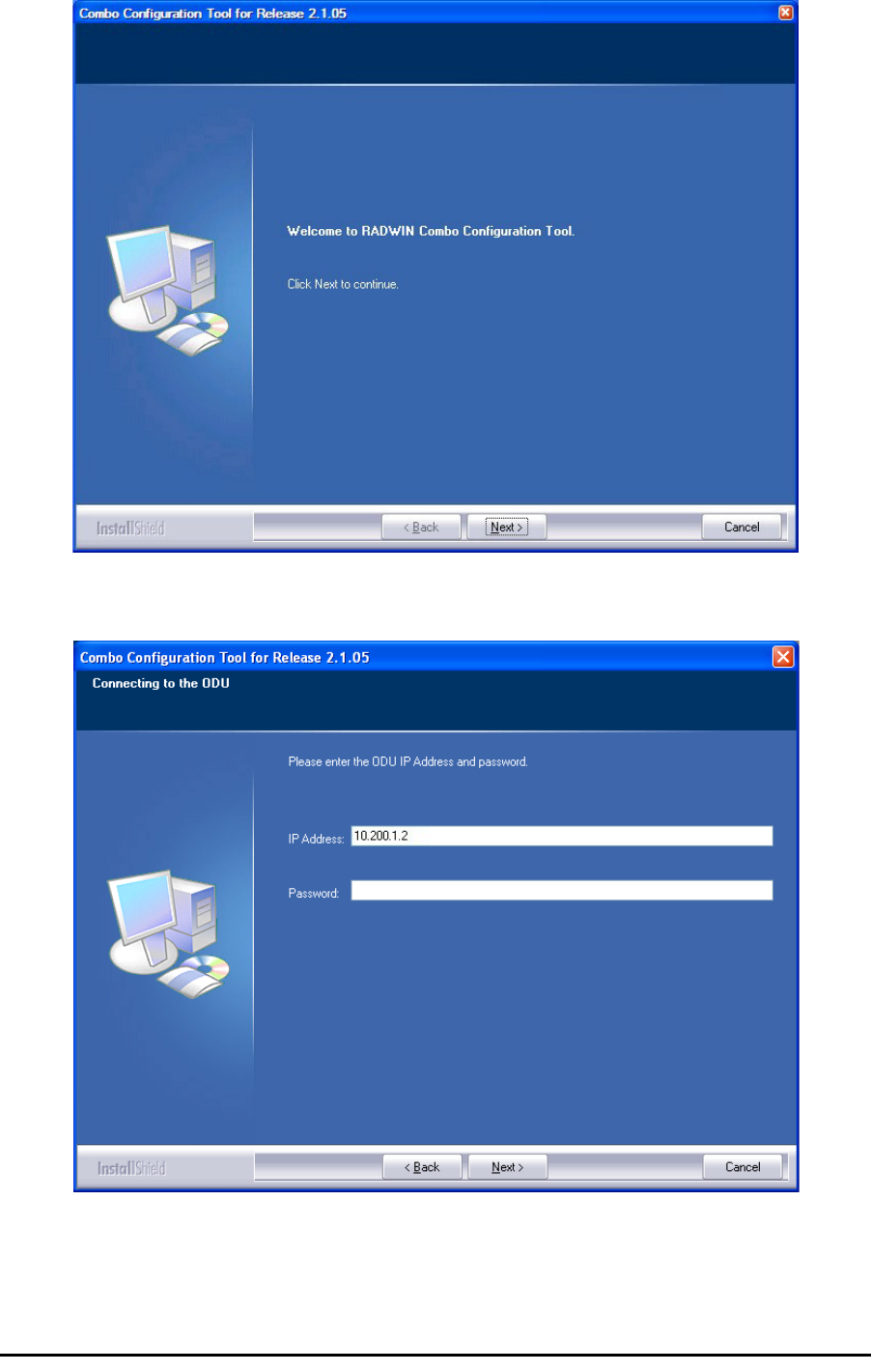
Using the Combo Configuration Tool Appendix H
RADWIN 1000/2000 User Manual Version 2.5p-4 H-3
2. Click Next. The window below is displayed:
3. Enter the ODU IP address and password.
4. Click Next. The following progress panel is displayed:
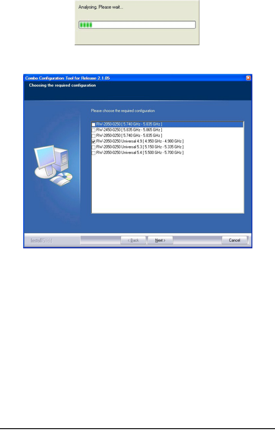
Using the Combo Configuration Tool Appendix H
RADWIN 1000/2000 User Manual Version 2.5p-4 H-4
Upon completion the following screen is displayed:
The checked item is the currently configured frequency band.
5. Check the box with the required frequency band. If you do not see the
required frequency band in the above window, click Cancel and consult
RADWIN Customer Support.
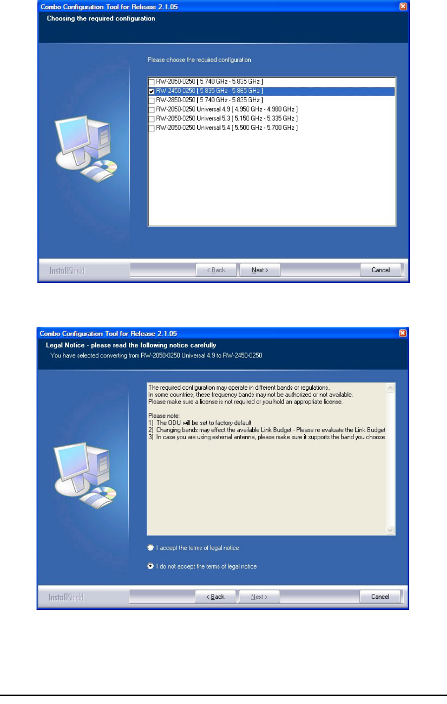
Using the Combo Configuration Tool Appendix H
RADWIN 1000/2000 User Manual Version 2.5p-4 H-5
.
6. Otherwise, click Next. The following window is displayed:
:
7. If the legal notice is acceptable, click the “I accept” radio button, and
then click Next. Two successive progress panels are displayed. The con-
figuration may take several minutes.
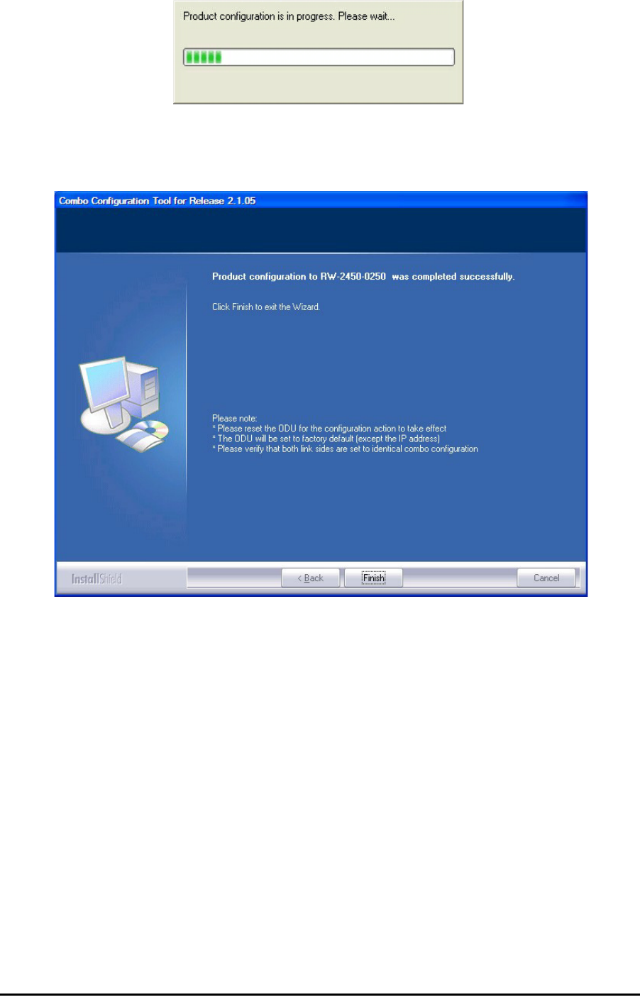
If you receive an error message Appendix H
RADWIN 1000/2000 User Manual Version 2.5p-4 H-6
Upon successful completion of the configuration process, the following
termination window is displayed:
8. Click Finish to exit the Wizard as shown.
9. Repeat the whole process for the second ODU in the link.
If you receive an error message
The last stage above may terminate unsuccessfully due to an error. Error
messages are posted to a window like this:
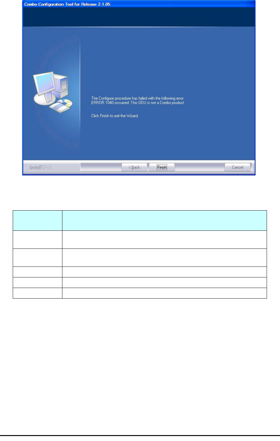
If you receive an error message Appendix H
RADWIN 1000/2000 User Manual Version 2.5p-4 H-7
The following table sets out possible errors:
The only items requiring explanation are errors 940 and 1020.
Error 940 may arise as a result of an ODU firmware problem. Error 1020 will
appear for any reason not caught by the other entries in the table. In all
such cases, you should consult with RADWIN Customer Support.
Error Number
(nn)
Error Text Message
Common mes-
sage preamble: The Configure procedure has failed with the following error: ERROR nn
occurred:
120 Failed to communicate with the ODU. Please verify the existence of a sta-
ble IP connection and try again.
940 Product is not identified.
1040 The ODU is not a Combo product.
1020 A configuration problem detected. Aborting.

RADWIN 1000/2000 User Manual Version 2.5p-4 I-1
Appendix I
Regional Notice: French
Canadian
Procédures de sécurité
Généralités
Avant de manipuler du matériel connecté à des lignes électriques ou de
télécommunications, il est conseillé de se défaire de bijoux ou de tout autre
objet métallique qui pourrait entrer en contact avec les éléments sous ten-
sion.
Mise à la terre
Tous les produits RADWIN doivent être mis à la terre pendant l'usage cou-
rant. La mise à la terre est assurée en reliant la fiche d'alimentation à une
prise de courant avec une protection de terre. En outre:
• La cosse de masse sur l'IDU-C doit être constamment connectée à
la protection de terre, par un câble de diamètre de 18 AWG ou plus.
Le matériel monté sur rack doit être installé seulement sur des racks
ou armoires reliés à la terre
• Une ODU doit mise à la terre par un câble de diamètre de 12 AWG
ou plus
• Il ne doit pas y avoir de fusibles ou d'interrupteurs sur la connection
à la terre
De plus:
• Il faut toujours connecter la terre en premier et la déconnecter en
dernier
• Il ne faut jamais connecter les câbles de télécommunication à du
matériel non à la terre
• Il faut s'assurer que tous les autres câbles sont déconnectés avant
de déconnecter la terre

Protection contre la foudre Appendix I
RADWIN 1000/2000 User Manual Version 2.5p-4 I-2
Protection contre la foudre
L'utilisation de dispositifs de protection contre la foudre dépend des exi-
gences réglementaires et de l'utilisateur final. Toutes les unités extérieures
RADWIN sont conçues avec des circuits de limitation de surtension afin de
minimiser les risques de dommages dus à la foudre. RADWIN conseille l'util-
isation d'un dispositif de parafoudre supplémentaire afin de protéger le
matériel de coups de foudre proches.
Matériel supplémentaire requis
L'équipement requis pour l'installation du matériel est le suivant:
• Pince à sertir RJ-45 (si un câble pré-assemblé ODU/IDU n'est pas
utilisé)
• Perceuse (pour le montage sur mur seulement)
• Câbles de terre IDU et ODU
•Clef 13 mm (½″)
• Câble ODU - IDU si non commandé (type extérieur, CAT-5e, 4 paires
torsadées, 24 AWG)
• Colliers de serrage
• Ordinateur portable avec Windows 2000 ou Windows XP.
Précautions de sécurité pendant le montage de ODU
Avant de connecter un câble à l'ODU, la borne protectrice de masse (visse)
de l'ODU doit être connectée à un conducteur externe protecteur ou à un
pylône relié à la terre. Il ne doit pas y avoir de fusibles ou d'interrupteurs
sur la connection à la terre.
Seulement un personnel qualifié utilisant l'équipement de sécurité approprié
doit pouvoir monter sur le pylône d'antenne. De même, l'installation ou le
démontage de ODU ou de pylônes doit être effectuée seulement par des
professionnels ayant suivi une formation.
¾Pour monter l'ODU:
1. Vérifier que les supports de fixation de l'ODU sont correctement mis à la
terre.
2. Monter l'unité ODU sur le pylône ou sur le mur; se référer à la Installa-
tion sur pylône et mur au dessous.
3. Connecter la câble de terre au point de châssis sur l'ODU.
4. Relier le câble ODU-IDU au connecteur ODU RJ-45.
5. Visser les presses-étoupe de câbles pour assurer le scellement hermé-
tique des unités ODU.
6. Attacher le
câble au pylône ou aux supports en utilisant des colliers clas-
s
és UV.
7. Répéter la procédure sur le site distant.

Connecter la terre à IDU-C Appendix I
RADWIN 1000/2000 User Manual Version 2.5p-4 I-3
Connecter la terre à IDU-C
Connecter un câble de terre de 18 AWG à la borne de masse de l'appareil.
L'appareil doit être constamment connecté à la terre.
Prudence
Ne pas se placer en face d'une ODU sous tension.
Prudence
• Les appareils sont prévus pour être installés par un personnel de ser-
vice.
• Les appareils doivent être connectés à une prise de courant avec une
protection de terre.
• Le courant CC du IDU-C doit être fourni par l'intermédiaire d'un dis-
joncteur bipolaire et le diamètre du câble doit être de 14 mm avec un
conduit de 16 mm.

Installation sur pylône et mur Appendix I
RADWIN 1000/2000 User Manual Version 2.5p-4 I-4
Installation sur pylône et mur
L' ODU ou l'O-PoE peuvent être montés sur un pylône ou un mur.
Contenu du kit de montage ODU
Le kit de montage ODU comprend les pièces suivantes:
• une grande clame (voir figure I-1)
• une
petite clame
(voir figure I-2)
• un bras (voir figure I-3)
• quatre visses hex tête M8x40
• deux visses hex tête M8x70
• quatre rondelles plates M8
• trois rondelles élastiques M8
• deux écrous M8.
Figure I-1:
grande clame
Figure I-2:
petite clame
Figure I-3:
bras
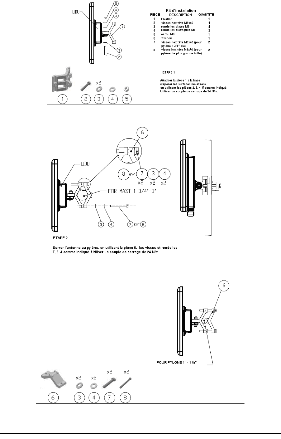
Montage sur un pylône Appendix I
RADWIN 1000/2000 User Manual Version 2.5p-4 I-5
Montage sur un pylône
Figure I-4: Montage sur un pylône
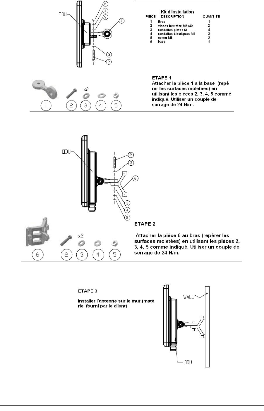
Montage sur un mur Appendix I
RADWIN 1000/2000 User Manual Version 2.5p-4 I-6
Montage sur un mur
Figure I-5: Montage sur un mur

Montage d'une antenne externe Appendix I
RADWIN 1000/2000 User Manual Version 2.5p-4 I-7
Montage d'une antenne externe
L'antenne externe optionnelle peut être montée sur un pylône.
Contenu du kit de montage d'une antenne externe
Le kit de montage d'une antenne externe comprend les pièces suivantes
• Douze rondelles plates
• Huit rondelles élastiques
• Huit écrous hex
•Quatre boulons
•Un support en U
• Un support à pivotement
• Deux courroies de fixation en métal
¾Pour installer une antenne externe sur un pylône:
1. Attacher le support en U à l'arrière de l'antenne en utilisant quatre ron-
delles plates, quatre rondelles élastiques et quatre écrous hex.
2. Attacher le support à pivotement au support en U en utilisant huit ron-
delles plates, quatre rondelles élastiques, quatre écrous hex et quatre
boulons.
3. Passer les deux courroies de fixation par les fentes verticales dans le sup-
port à pivotement.
4. Attacher l'antenne au pylône en utilisant les deux courroies de fixation .
Ajuster l'inclinaison nécessaire en utilisant l'échelle angulaire et serrer tous
les boulons et écrous à la position requise.

RADWIN 1000/2000 User Manual Version 2.5p-4 Index 1
Index A
AAR 1-3
ACS 4-17, 6-20, F-8, F-8
aging time, ODU Bridge Mode 6-10
Air Interface 1-11, 1-11
Technical Specifications, general A-1
Alarms
Active 7-9
summary 7-14
Connector B-3
External , specification G-1
Antennas
Align with beeper 3-12
Aligning 3-12
bipolar 3-12
Buzzer signals 3-13
monopolar 3-13
Cable, grounding E-1
Connecting 3-12
Described 1-8
External
Mounting 3-7
Package Contents 3-5
External, Mounting C-3
Flat panel 1-10
Parabolic Dish 1-10
Settings 4-19, 5-18
types 1-7
Applications
Broadband Access 1-2
IP Backhaul 1-2
Private Networks 1-2
WiMAX 1-2
Automatic Adaptive Rate, see AAR 1-3
Automatic Channel Selection, see ACS
Automatic Repeat Request 1-4
B
backup
configuration file 6-2
ODU replacement 7-16
Beeper
mute 6-17
muting and restoring 6-3
restore 6-17
Bridge mode,Telnet commands 6-21
Buzzer, see Beeper
C
Changing link password 4-16
Channel, selecting 4-17, 5-12
Community Strings
Changing 6-16
Editing 6-15
Factory Default 6-14, F-2
Forgotten passwords 6-16
MIB F-2
passwords 4-4
Read-Only 6-14
Read-Write 6-14
Trap 6-14
Configuration Parameters 6-3
Configuring
Advanced 6-2, 6-9, 6-11, 6-12, 6-18
Air Interface 6-2
Air interface 5-1
Bridge mode 6-1
Community values. 6-1
contact person 6-2
Date and Time 6-2
Ethernet mode 6-1
Frequency channel 5-1
Security 6-2
Service parameters 5-1
System 6-2
System parameters 5-1
Transmit power 6-1
View Inventory 6-2
Connecting user equipment 4-17, 5-12
Customer Support 7-17
D
Date and time, setting 6-2, 6-7
Default log on password 4-4
E
Events
color codes 7-12
log 7-2, 7-4
priority 7-13
Index

RADWIN 1000/2000 User Manual Version2.5p-4 Index 2
F
Factory Defaults 6-14, F-2
Reset to 6-19
Factory Setup
Restoring 7-17
FEC 4-21, 4-22, A-2, A-3
Forward Error Correction, see FEC
G
Gateway 6-2
Telnet display 6-20
I
IDUAging time 6-10
aging time, ODU Bridge Mode 6-10
Connecting to ODU 3-11
described 1-7
IDU-C
Alarm Connector B-3
Connectors B-4
Front panel 1-8
Described 3-9
LEDs 3-9, 3-10, 4-2
Mounting 3-8
Power connections 3-11, 3-11
Package Contents 3-4
Products 1-7
Indoor Unit, see IDU
Installation
Menu and Toolbar Functionality 4-10
Post Configuration main window 5-22
Post Installation main window 4-27
see Link, Installation
Installation Mode 6-3, 6-3, 6-12
Inventory 6-16
Displaying 6-12
IP address 6-2
Telnet display 6-20
K
Key Features of Radio Link
Advanced Air Interface 1-3
Capacity 1-3
Combo Frequency Products 1-3
Installation and management 1-4
Range performance 1-4
Security 1-4
Spectral Efficiency 1-3
Transmission (Tx) power 1-4
L
LBC 7-4
Browser warnings D-6
Calculations D-2
Climactic C Factors D-10
described D-1
Fresnel Zone, described D-13
Internal data D-1
Running D-3
User input D-1
Lightning and Grounding Guidelines E-1
LinkBudget Calculator, see LBC
Configuration 5-1
Overview 5-10
Step 1 - Start Wizard 5-11
Step 2- System Parameters 5-11
Step 3 - Channel Settings 5-12
Step 4 - Tx Power and Antenna Settings
5-18
Step 5 - Services 5-20
Step 6 - Summary and exit 5-21
default frequency 4-18
default Settings 4-9
Information 7-1
Air Interface Thresholds
BBER Threshold 7-9
RSL Threshold 7-9
Air Interface Thresholds, setting 7-9
Alarms
Active summary 7-14
Error detection and 7-14
output 7-15
saved 7-14
Compatibility 7-3
Trap messages 7-3
Events Log 7-4
Events log
Events references
trapbackground color 7-13
default colors 7-13
foreground color 7-12
Preferences 7-12
saving 7-13
Monitor log 7-4, 7-4
saving 7-4
Online Help 7-17
Performance data, explained 7-8
Performance monitoring 7-4
Performance Reports 7-5
Remote Power Fail Indication 7-15
“Dying-Gasp” circuit 7-15
Troubleshooting 7-16
Installation 4-7
ODU
Mast and Wall C-1
Overview 4-13
Step 1 - Start Wizard 4-14
Step 2 - System Parameters 4-14
Step 3 - Channel Settings 4-17
Step 4 - Tx Power and Antenna Settings

RADWIN 1000/2000 User Manual Version2.5p-4 Index 3
4-19
Background 4-20
Step 5 - Services 4-25
Step 6 - Summary and Exit 4-26
Link ID 4-9, 4-15, 6-20, 7-16, 7-16, 7-17
Login 4-3
Login Errors
Incorrect IP Address 4-6
Incorrect password 4-6
Unsupported Device 4-5
Login showing Community Options 4-5
Manager Software 4-2
Name 4-15
Password 1-5, 7-17
changing 4-16
Post Configuration main window 5-22
Post Installation main window 4-27
Reinstalling/Realigning 7-3
Site names 4-15
Link Budget Calculator, see LBC 7-4
Link ID 4-9, 4-15, 6-20, 7-16, 7-16, 7-17
Link Site
Planning 2-1
Survey 2-1
Stage 1 - Preliminary Survey 2-2
Stage 2 - Physical Survey 2-3
Additional Indoor Site Requirements
2-4
Additional Outdoor Site Requirements
2-4
Stage 3 - RF Survey 2-4
Login Errors
Incorrect IP Address 4-6
Incorrect password 4-6
Unsupported Device 4-5
M
Management
Addresses 6-4
and trap addresses 6-1
Configuring the Site 6-2
Screen, Telnet 6-22
Manager Software
Change log on password 4-7
Events Log 5-8
Installing 4-1
Main window 5-1
Details pane 5-6
Main menu 5-3
Toolbar 5-2
main window 4-5
Monitor pane 5-7
Ethernet Service
5-7
Radio Interface, 5-7
Radio signal strength 5-7
Off-line functionality 4-6
Status Bar 5-9
Manual
Chapters by Audience 1-13
Conventions 1-15
Terminology 1-13
MIBAbout F-1
Community String F-2
Interface API F-1
Parameters F-4
Private F-2
Private Parameters F-5
Reference F-1
Supported Variables from the RFC 1213 F-4
Terminology F-1
Traps F-18
Parameters F-18
O
ODU 1-6
Bridge Mode
aging time 6-10
Connectorized 1-5, 1-6
described 1-5
form factors 1-6
Installation, Mast and Wall C-1
Integrated Antenna 1-5, 1-6
Mounting Kit C-1
Package Contents 3-2
Products 1-7
Replacing 7-16
With integrated antenna 1-9
P
Package, contents of 3-2
Password
Community 4-4, 4-4
Default 4-4
default log on 4-4
Link 1-5, 7-17
PC, Minimum Requirements 4-1
Performance
Monitor 7-2
Performance Monitoring, set time interval 7-4
PoEDescribed 1-8
PoE device, see PoE
Power over Ethernet, see PoE
Protection
External Lightning Surge Suppressors E-3
Grounding
Antenna cable E-1
IDUs E-2
ODUs E-2
Internal ESD Protection circuits E-7

RADWIN 1000/2000 User Manual Version2.5p-4 Index 4
R
Radio Link
Accessories 1-12
Additional Tools and Materials Required 3-5
Connecting user equipment 3-12
Described 1-5
Documentation set 1-12
Hardware Installation
External Antennas 3-7
Indoor 3-8
Lightning protection 3-7
Mounting U 3-8
ODU 3-6
Outdoor 3-6
Outdoor connections 3-8
Sequence 3-5
Package Contents 3-2
IDU 3-4
ODU 3-2
Package contents
External Antennas 3-5
Transmission rates 4-22
Radio Outdoor Unit, see ODU
Replacing an ODU 7-16
restore configuration file 6-2
S
Safety Practices 3-1
Grounding 3-1
Preventing overexposure to RF energy 3-1
Selecting channel 4-17, 5-12
Site Configuration
Configuration Files 6-18
backup to 6-18
Configuration files
restore from 6-19
Configuration with Telnet 6-20
Dialog
Change Tx Power 6-4
Ethernet Properties 6-9
Configuring
Bridge 6-9
Maximum information rate 6-12
Ports Mode 6-11
Ethernet PropertiesIDU Aging time 6-
10
Functions 6-2
Inventory 6-12
Menu bar 6-2
Setting the date and time 6-7
View Air Iinterface details 6-3
VLAN Settings 6-5
Lost or forgotten VLAN ID 6-7
Priority number 6-6
VLAN ID 6-6
External Alarm Inputs 6-17
Reset site 6-19
Reset site to factory defaults 6-19
Reset site, preserve current configuration
6-19
Security Features 6-13
Community Strings 6-14
Editing 6-15
Forgotten paswwords 6-16
Initial log on defaults 6-15
Default Gateway 6-5
IP address 6-5, 6-5
Trap Destination 6-5
T
Technical Specifications
Air Interface A-4
Air Interface, general A-1
Configuration A-1
EMC A-4
Environmental A-4
Ethernet Interface A-3
Management A-3
Mechanical A-3
Power A-3
Radio A-1
Safety A-4
Trap messages 7-3
typical installation 3-5
U
User equipment, connecting 4-17, 5-12
W
Wiring Specifications B-1
Alarm
Connector
IDU-C B-3
Connectors
IDU-C B-4
User Port B-1
LANPorts B-1
ODU-IDU Cable B-1
Ports
LAN B-1
User Port Connectors B-1