Radwin RW2058U Outdoor radio unit operating in 5.8 GHz bands User Manual STW
Radwin Ltd. Outdoor radio unit operating in 5.8 GHz bands STW
Radwin >
Contents
- 1. Manual U1
- 2. Manual U2
- 3. Manual U3
- 4. Manual U4
- 5. Manual
Manual U3

RADWIN 1000/2000 User Manual Version 2.5p-4 6-1
Chapter 6
Site Configuration
The Site Configuration dialog panels are used to configure parameters,
which may differ between both sides of the link.
The parameters configured using the Site Configuration dialog panels
include (among others):
• System settings
• Air interface - Transmit (Tx) power and antenna
• Network management including VLAN
• Security settings
• Date and time
• Hub or Bridge mode
In addition, the Link Site Configuration panels include several information
windows:
• Inventory - link hardware and software model details
• External alarms indicators
The Operations dialog offers a “doorway” to jump into installation mode
reverting to factory settings.
The Site Configuration dialog has its own main menu with the following
extra functionality:
• Backup configuration parameters to a text file
• Restore configuration from a previously backed up configuration file
• Enable/disable the site ODU buzzer
• Jump back into installation mode keeping current configuration set-
tings
Configuring the Site
Editing the Configuration Parameters by Site
You can edit the configuration parameters for each site individually. The fol-
lowing functions are available from the left side of the dialog box.
Editing the Configuration Parameters by Site Chapter 6
RADWIN 1000/2000 User Manual Version 2.5p-4 6-2
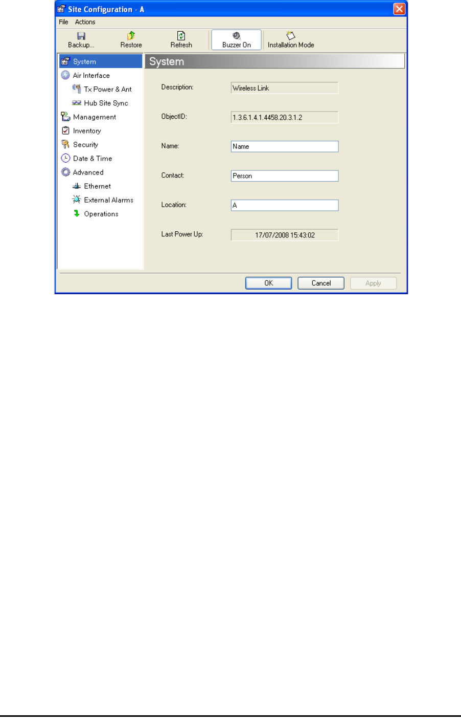
Figure 6-1: Configuration Dialog Box
Functions on the left of the dialog box:
Functions at the top of the dialog box:
System Edit the contact person and location details.
View the system details
Air Interface Change the transmit power, cable loss, antenna
type and settings
Inventory View the hardware and software inventory
(release numbers, model identification, MAC
address)
Management Configure the IP address, Subnet Mask, Default
Gateway, the Trap Destination and VLAN
Security Change the Community Values and the Link
Password
Date and Time Set the date and time of the link from an NTP
servers otherwise
Advanced Choose Hub or Bridge ODU mode, set the
Ethernet ports configuration, set the external
alarm inputs, restore factory settings
Backup Save the current configuration to an .ini file
Restore Restore the link configuration from the .ini file
created by the backup
Viewing Air Interface Details Chapter 6
RADWIN 1000/2000 User Manual Version 2.5p-4 6-3
¾To edit the Configuration Parameters:
1. Click the required site button on the main tool bar of the RADWIN Man-
ager
OR
Click Configuration from the main menu and choose a site to config-
ure.
The Configuration dialog box opens (see figure 6-1 above).
2. Choose the appropriate item in the left hand list to open a dialog box.
3. Click Apply to save changes.
In subsequent instructions, we will simply say “Choose a site to configure”
on the understanding that the foregoing procedure is implied.
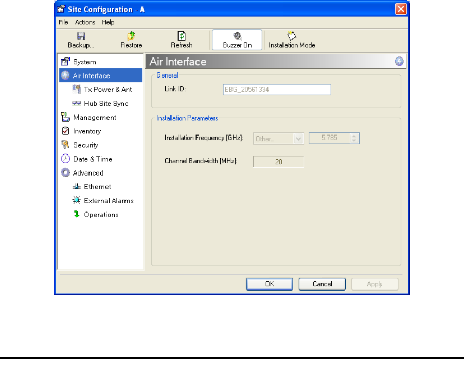
Viewing Air Interface Details
Click the Air Interface item in the left hand list. A window similar to the fol-
lowing appears:
Figure 6-2: Air interface details
Installation
Mode
Return to Installation Mode for the entire link.
Selecting the Mute check box before clicking
the Install Mode button mutes the Beeper.
Mute Mutes the alignment tone in installation mode.
Reactivate the beeper during alignment.
Changing the Transmit Power Chapter 6
RADWIN 1000/2000 User Manual Version 2.5p-4 6-4
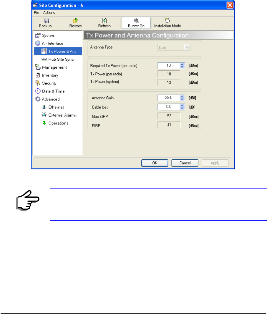
Changing the Transmit Power
Each site can have a different transmit power level.
¾To change the Transmit Power:
1. Choose a site to configure.
The Configuration dialog box opens.
2. Choose Air Interface (see figure 6-3).
3. Choose the required Transmit (Tx) Power Level.
4. Click Apply to save the changes.
Figure 6-3: Changing the Transmit Power
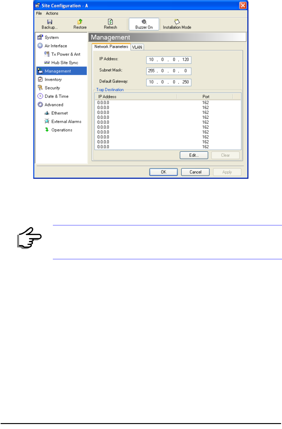
Site Management: IP Address and VLAN
Configuring the ODU Address
Each site must be configured separately, first site A then site B.
¾To define the Management Addresses:
1. Choose a site to configure.
Note
The same considerations apply here as were noted in the Installation
procedure on page 4-23.
Configuring VLAN Settings Chapter 6
RADWIN 1000/2000 User Manual Version 2.5p-4 6-5
The Configuration dialog box opens:
Figure 6-4: Management Addresses - Site Configuration dialog box
5. Choose Management.
6. Enter the IP address of the ODU in the IP Address field.
7. Enter the Subnet Mask.
8. Enter the Default Gateway.
9. Enter the Trap Destination. This could be the IP address of the managing
computer. The events log will be stored at this address.
10.Click Apply to save the changes.
Configuring VLAN Settings
VLAN Management enables separation of user traffic from management
traffic whenever such separation is required. It is recommended that both
sides of the link be configured with different VLAN IDs for management traf-
fic.
¾To enable VLAN management:
1. Click Configuration from the main menu.
Note
If performing configuration from the RADWIN Manager, the IP address is
that entered from the login screen.
Configuring VLAN Settings Chapter 6
RADWIN 1000/2000 User Manual Version 2.5p-4 6-6
2. Choose a site to configure. If you are configuring both sites, choose site
B first.
3. Choose Management.
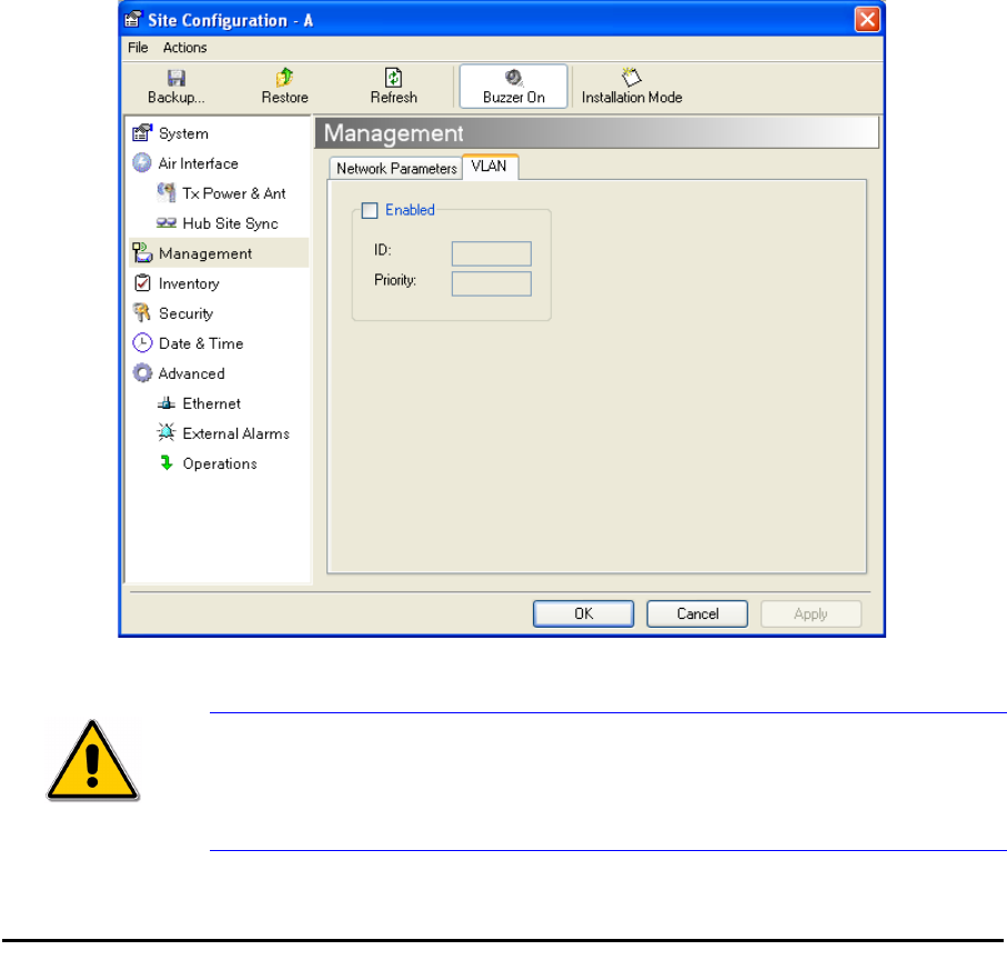
4. Open the VLAN tab.
5. Check the Enabled box.
6. Enter a VLAN ID. Its value should be between 1 and 4094.
After entering the VLAN ID, only packets with the specified VLAN ID are
processed for management purposes by the ODU. This includes all the
protocols supported by the ODU (ICMP, SNMP, TELNET and NTP). The
VLAN priority is used for the traffic sent from the ODU to the managing
computer. Using VLAN for management traffic affects all types of man-
agement connections (local, network and over the air).
7. Enter a Priority number between 0 and 7.
8. Change the VLAN ID and Priority of the managing computer NIC to be
the same as those of steps 6 and 7 respectively.
9. Click Apply or OK.
Figure 6-5: Configuring management traffic VLAN Settings
Caution
Changing this parameter causes the RADWIN Manager to immediately
disconnect.To avoid inconvenience, you should verify the change by
setting the VLAN only to one ODU, and only after verifying proper
management operation, change the other ODU VLAN setting.

Setting the Date and Time Chapter 6
RADWIN 1000/2000 User Manual Version 2.5p-4 6-7
Lost or forgotten VLAN ID
If the VLAN ID is forgotten or there is no VLAN traffic connected to the
ODU, then reset the relevant ODU.
During the first two minutes of connection to the ODU uses management
packets both with and without VLAN. You may use this period to reconfigure
the VLAN ID and priority.
Setting the Date and Time
The ODU maintains a date and time. The date and time should be synchro-
nized with any Network Time Protocol (NTP) version 3 compatible server.
During power-up the ODU attempts to configure the initial date and time
using an NTP Server. If the server IP address is not configured or is not
reachable, a default time is set.
When configuring the NTP Server IP address, you should also configure the
offset from the Universal Coordinated Time (UTC). If there is no server
available, you can either set the date and time, or you can set it to use the
date and time from the managing computer. Note that manual setting is not
recommended since it will be overridden by a reset, power up, or synchroni-
zation with an NTP Server.
¾To set the date and time
1. Determine the IP address of the NTP server to be used.
2. Test it for connectivity using the command (Windows XP), for example:
w32tm /stripchart /computer:216.218.192.202
You should get a continuous response of times, each a few seconds
apart.
3. Choose a site to configure.
The Configuration dialog box opens.
4. Choose Date & Time:
Note
The NTP uses UDP port 123. If a firewall is configured between the ODU
and the NTP Server this port must be opened.
It can take up to 8 minutes for the NTP to synchronize the ODU date and
time.
Setting the Date and Time Chapter 6
RADWIN 1000/2000 User Manual Version 2.5p-4 6-8
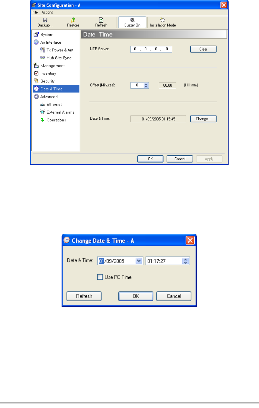
Figure 6-6: Date and Time Configuration
5. If entering an IP address for the NTP Server, click Clear, and then enter
the new address.
6. Set your site Offset value in minutes ahead or behind GMT1.
7. To manually set the date and time, click Change and edit the new values.
Figure 6-7: Change Date and Time
If you used an NTP Server, you will see a window like this:
1. Greenwich Mean Time
Ethernet Properties Chapter 6
RADWIN 1000/2000 User Manual Version 2.5p-4 6-9
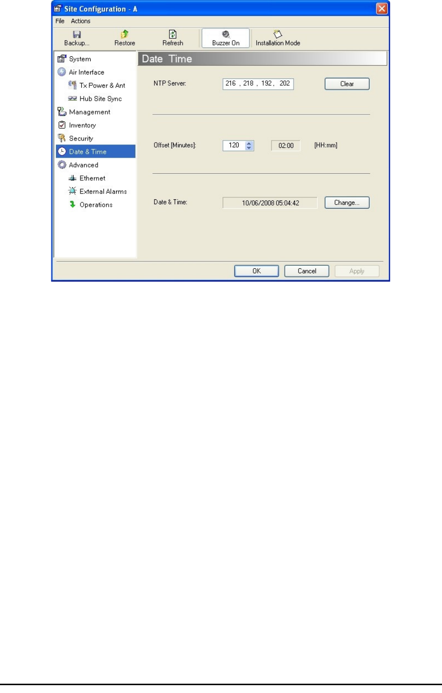
Figure 6-8: Date and Time configured from an NTP Server
8. Click OK to return to the Configuration dialog.
Ethernet Properties
Configuring the Bridge
Bridge configuration is required in various network topologies, such as pro-
tection (1+1) and ring applications. The bridge configuration parameters
are located under the Advanced tab of the Site Configuration dialog box:
Configuring the Bridge Chapter 6
RADWIN 1000/2000 User Manual Version 2.5p-4 6-10
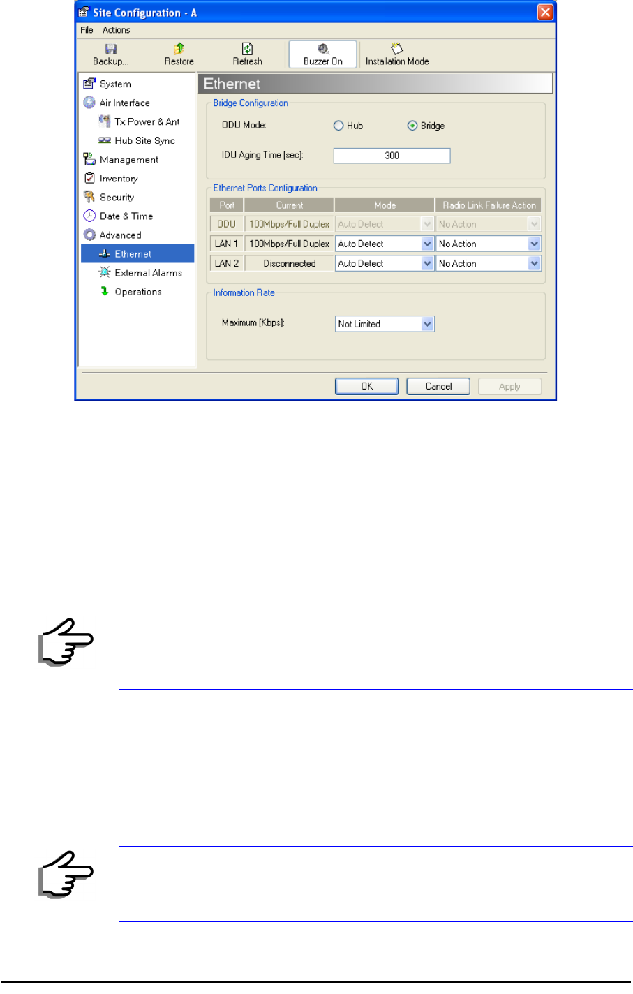
Figure 6-9: Bridge Configuration - Site Configuration dialog box
ODU Mode
This parameter controls the ODU mode with two optional values,
• Hub Mode - in Hub mode the ODU transparently forwards all packets
over the wireless link.
• Bridge Mode - In Bridge mode the ODU performs both learning and
aging, forwarding only relevant packets over the wireless link. The
aging time of the ODU is fixed at 300 seconds.
IDU Aging time
This parameter controls the IDU aging time.
The aging time parameter controls the time after which each MAC address
is dropped from the MAC address learning table.
The default value is 300 seconds.
Note
Changing these modes requires system reset.
Note
• Any change to these parameters is effective immediately.
• Each side of the link can be configured separately.
Configuring Ethernet Ports Mode Chapter 6
RADWIN 1000/2000 User Manual Version 2.5p-4 6-11
The following table shows the appropriate configuration for several common
scenarios. Both link sites must be configured with the same parameter:
Configuring Ethernet Ports Mode
The ODU Ethernet port is configured to auto-detect by default and may not
be changed.
The ODU Ethernet port mode is configurable for line speed (10/100BaseT)
and duplex mode (half or full duplex).
An Auto Detect feature is provided, whereby the line speed and duplex
mode are detected automatically using auto-negotiation. Use manual con-
figuration when attached external equipment does not support auto-negoti-
ation. The default setting is Auto Detect.
¾To configure the Ethernet Mode:
1. From the Configuration menu, choose the site to reconfigure.
The Site Configuration dialog box opens.
2. Click Advanced | Ethernet.
3. In the Ethernet Ports Configuration pane, use the drop-down menu to
choose the configuration.
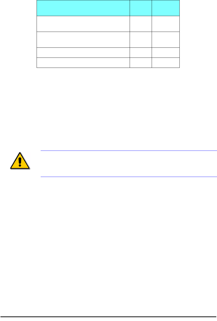
Table 6-1: ODU mode configuration for common
Scenario ODU
Mode
IDU Aging
Time
Standard (Default) Configuration for
Ethernet Applications
Bridge 300 sec
Rapid network topology changes
where fast aging is required
Hub 1 sec
Ethernet Hub Hub N/A
Ethernet Bridge Bridge N/A
Caution
You should not reconfigure the port that is used for the managing computer
connection, since a wrong configuration can cause a management
disconnection or Ethernet services interruption.

Setting the Maximum Information Rate Chapter 6
RADWIN 1000/2000 User Manual Version 2.5p-4 6-12
4. Click Apply to save the changes.
Setting the Maximum Information Rate
The maximum Ethernet throughput of the link can be limited. The default
setting is Not Limited (see figure 6-9 above), where the highest informa-
tion rate available for the link conditions and settings is used.
¾To limit the Ethernet information rate:
1. From the Configuration menu, choose the site to reconfigure.
2. Click Advanced | Ethernet
The Configuration dialog box opens.
3. In the Information Rate pane, use the drop-down menu to choose the
maximum Information Rate.
4. Choose Other to define the throughput with 1 Kbps resolution
5. Choose Not Limited for the highest information rate possible for the
link conditions and settings
6. Click Apply to save the changes.
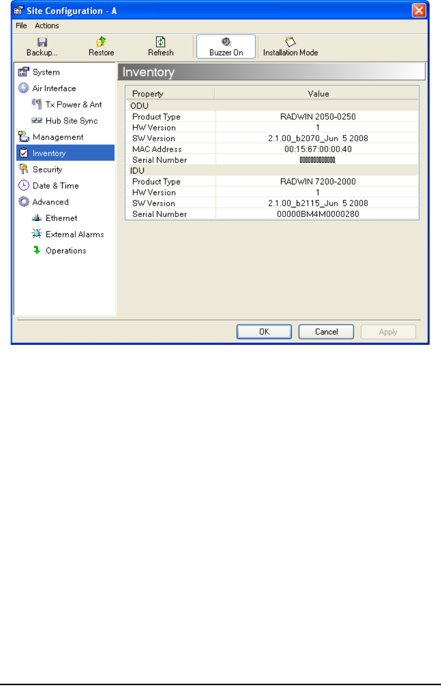
Displaying the Inventory
¾To view the inventory data
1. Choose a site from the main menu.
The Configuration dialog box opens.
2. Choose Inventory (figure 6-10).
Note
It is possible to close the Ethernet service by disconnecting the Ethernet
port.
If you close the port, you may subsequently be unable to access the
device. If this should occur, a workaround is as follows:
• Connect the system from the remote site
• Connect via other Ethernet port (of the IDU)
• Power down the equipment and connect immediately after power
up (the fastest way is to enter install mode)
Security Features Chapter 6
RADWIN 1000/2000 User Manual Version 2.5p-4 6-13
Figure 6-10: Inventory Screen
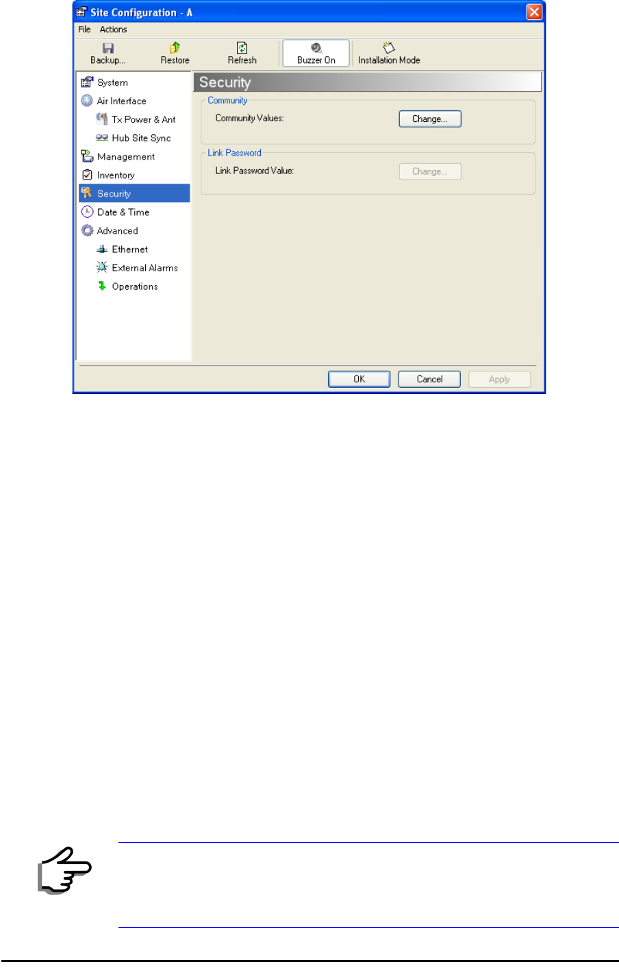
Security Features
The Security dialog enables you to change the Link Password and the SNMP
Communities details:
Changing the Link Password Chapter 6
RADWIN 1000/2000 User Manual Version 2.5p-4 6-14
Figure 6-11: Available security features
Changing the Link Password
This item is only available when the link is down. Otherwise, it works the
same way as the corresponding item on page 4-16.
RADWIN Manager Community Strings
The ODU communicates with the application using SNMPv1 protocol. The
protocol defines three types of communities:
• Read-Only for retrieving information from the ODU
• Read-Write to configure and control the ODU
• Trap used by the ODU to issue traps.
The Community string must be entered at login. The user must know the
password and the correct Community string to gain access to the system. A
user may have read-only privileges.
It is not possible to manage the ODU if the read-write or the read Commu-
nity values are forgotten. A new Community value may be obtained from
RADWIN Customer Support for the purpose of setting new Community; the
serial number or the MAC address of the ODU must be supplied.
Note
The RADWIN Manager uses the Read Community strings public for the site
Al ODU and public-remote for the site B ODU. It uses Write Community
strings netman for the site A ODU and netman-remote for the site B
ODU. These are the factory defaults.

RADWIN Manager Community Strings Chapter 6
RADWIN 1000/2000 User Manual Version 2.5p-4 6-15
The read-write Community strings and read-only Community strings have a
minimum of five alphanumeric characters. (bru1 and bru4097 are not per-
mitted). Changing the trap Community is optional and is done by clicking
the check box.
Editing Community Strings
The Community change dialog box is available from the Configuration |
Security tab. Both read-write and read-only communities must be defined.
On logging on for the first time, use the following as the current Commu-
nity:
• For Read-Write Community, use
netman
.
• For Read-Only Community, use
public
.
• For Trap Community, use
public
¾To change a Community string:
1. From the Configuration dialog box, choose the Security tab.
2. Type the current read-write Community (default is
netman
).
3. Choose the communities to be changed by clicking the check box.
4. Type the new Community string and re-type to confirm.
5. Click OK to save.
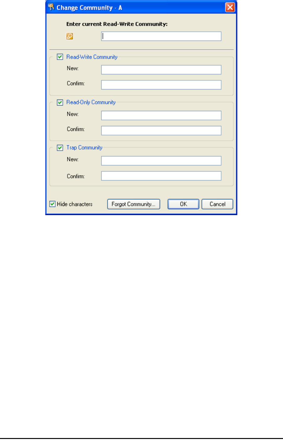
RADWIN Manager Community Strings Chapter 6
RADWIN 1000/2000 User Manual Version 2.5p-4 6-16
Figure 6-12: Changing the Community String
Forgotten Community string
If the read-write Community string is unknown, an alternative Community
key can be used. The alternative Community key is unique per ODU and can
be used only to change the Community strings. The alternative Community
key is supplied with the product, and should be kept in a safe place.
If both the read-write Community and the alternative Community key are
unavailable, then an alternative Community key can be obtained from RAD-
WIN Customer Support using the ODU serial number or MAC address. The
serial number is located on the product label. The serial number and the
MAC address are displayed in the Site Configuration inventory tab.
When you have the alternative Community key, click the Forgot Commu-
nity button and enter the Alternative Community key (figure 6-13). Then
change the read-write Community string.
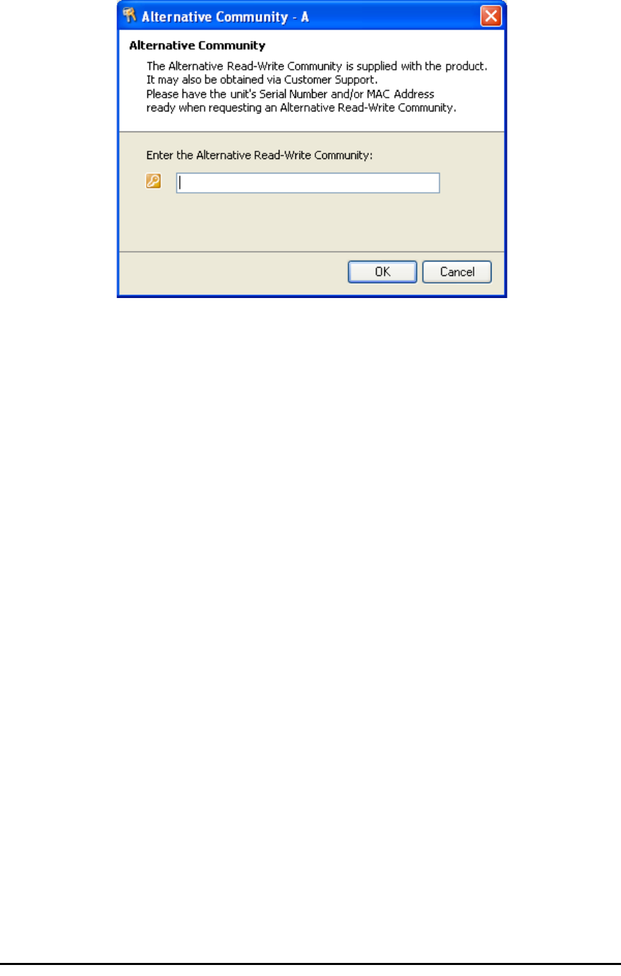
Muting the alignment tone Chapter 6
RADWIN 1000/2000 User Manual Version 2.5p-4 6-17
Figure 6-13: Alternative Community Dialog box
Muting the alignment tone
The ODU alignment tone becomes audible as soon as power is supplied,
and continues until the ODUs are aligned and the link established.
It is possible to mute the tone during regular operation of the link. It must
be enabled when performing the alignment procedure.
¾To mute the alignment tone:
1. Choose a site.
2. The Configuration dialog box opens.
3. In the Configuration dialog box, click the Buzzer button. The button tog-
gles between on and off.
The tone is disabled.
¾To restore the alignment tone:
1. Choose a site.
The Configuration dialog box opens.
2. In the Configuration dialog box, click the Buzzer button. The button tog-
gles from on to off. The tone is enabled.
Setting External Alarm Inputs
The IDU-C has two external alarm inputs and two external alarm outputs in
the form of dry-contact relays. The Alarm interface is located on the front
panel of the IDU-C and is a 25-pin D-type female connector. see IDU-C
Alarm Connector on page B-3, for wiring specifications and pinout. The
user enables or disables each of the alarms and can configure the alarm
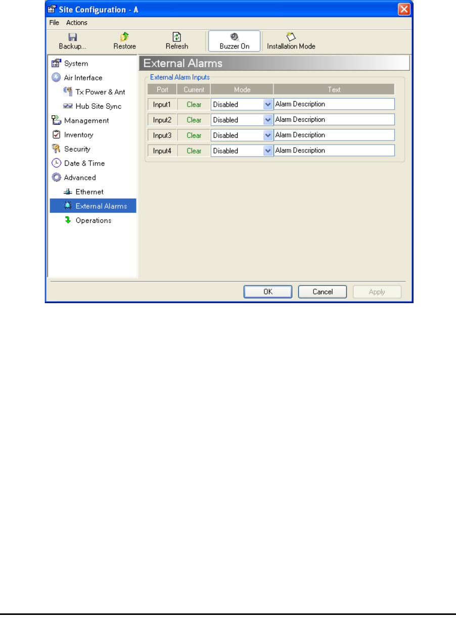
Managing Configuration Files Chapter 6
RADWIN 1000/2000 User Manual Version 2.5p-4 6-18
description text that appears in the alarm trap. The ODU sends the alarm
within less than a second from actual alarm trigger.
¾To set the external alarm inputs:
1. Open the Site Configuration Alarms configuration by clicking Configura-
tion | Advanced.
Figure 6-14: External Alarm Configuration
2. Choose an alarm and set its mode to Enabled or Disabled
3. Enter a description of the alarms in the text field.
4. Click Apply to save.
5. Click OK to exit from the dialog.
Managing Configuration Files
Backup Configuration to a File
RADWIN Manager allows you to backup configuration parameters of the
local and remote units to the managing computer as .ini files. Each site is
backed up in a separate .ini file.
¾To save the configuration in a file:
1. Choose a site to back up.
The Configuration dialog box opens.
Restoring a Configuration File Chapter 6
RADWIN 1000/2000 User Manual Version 2.5p-4 6-19
2. Click Backup.
3. In the Save As dialog box, indicate in which folder and under what name
configuration file is to be saved, and click Save.
Restoring a Configuration File
Configuration files (*.ini) can be uploaded from the managing computer.
Such configuration files can be distributed to other units that use the same
configuration.
¾To restore a configuration file:
1. Choose a site to restore (from a previous backup).
The Configuration dialog box opens.
2. Click Restore.
3. From the Open dialog box choose *.ini file to upload and click OK.
Resetting
You may reset the link, preserving the current configuration, or reset to fac-
tory defaults.
¾To reset the link preserving current configuration:
1. From Maintenance on the main window, reset the remote unit.
2. From Maintenance on the main window, reset the local unit.
¾To reset to Factory Defaults
1. Choose either of the sites.
The Configuration dialog box opens.
2. Choose Operations in the Configuration dialog box.
3. Click the Restore Defaults button.
A message box asking if you want to restore factory default appears.
4. Click the check box if you want to keep the current IP address settings.
5. Click Yes to continue.
Caution
Backup files are specific to a site (IDU / ODU pair and Link ID).
Do not restore a backup configuration file to a site other than that from
which it was originally taken.
Caution
Resetting the link causes service disconnection.
To maintain the connection between the managing computer and
the link, first reset Site B.

Configuration with Telnet Chapter 6
RADWIN 1000/2000 User Manual Version 2.5p-4 6-20
Configuration with Telnet
A Telnet terminal can be used to configure and monitor the RADWIN 1000/
2000.
To start a Telnet session, use telnet <manager IP>.
For example, if you run Telnet as follows,
telnet 10.0.0.120
you will be asked for a user name and password.
The login user name/password is identical to the Community strings; Read
allows display only, Read/Write allows display and set commands.
Supported Telnet commands are shown in table 6-2. Note that some of the
commands are model-specific. For example, TDM commands will not apply
to Ethernet only and PoE based links.
Table 6-2: Telnet Commands
Command Explanation
display inventory Displays ODU product name, Name, Location, hardware
and software revisions, uptime, MAC address, IDU product
name, IDU software and hardware revisions
display management Displays IP, Subnet, Gateway, Traps table
display link Displays State, Link ID, Channel BW, RSS, TSL,
Frequency/ACS, DFS, Rate/ARA, Distance
display Ethernet Displays Bridge Mode, Aging time, Port table (State, Status
and action)
display tdm Displays Clock Mode, Master Clock Mode, Current Clock,
Quality[1], TDM table (Line status, Error Blocks)
display ntp Displays Time, Server and Offset
set ip <ipaddr> <subnetMask>
<gateway>
Set the ODU IP address, subnet mask and gateway
The user must reset the ODU after the command
completion
display PM
<interface:AIR,LAN1,LAN2,TDM1,
TDM2,TDM3,TDM4>
<interval:current,day,month>
Shows the performance monitor tables for each interface
according to user defined monitoring intervals
set trap <index:1-10> <ipaddr>
<port:0-65535>
Set a specific trap from the traps table (set trap 3
10.0.0.133 162)
set readpw <oldpasswd> <passwd> Set the read access password (Read Community)
set writepw <oldpasswd> <passwd> Set the read-write access password (Read-Write
Community)
set trappw <oldpasswd> <passwd> Set the trap Community string
set buzzer <mode:0=OFF,1 =ON> Toggle the buzzer mode (0 – off, 1 – on)

Configuration with Telnet Chapter 6
RADWIN 1000/2000 User Manual Version 2.5p-4 6-21
set tpc<power:Value between minimal
TX power, and maximal TX power>
Set the ODU transmit power. If a wrong value is entered,
both min and max values shall be displayed in the error
reply
set bridge <mode:0=Bridging OFF,1=
Bridging ON >
Set the ODU bridge mode (0 – off, 1 – on)
set name <new name> Set the name of the link
set location <new location> Set the name of the location
Set contact <new contact> Set the name of the site manager
set Ethernet <>port:MNG,LAN1,LAN2>
<mode:AUTO,10H,10F,100H,100F,DIS
ABLE>
Set the mode and speed of each ethernet port
Reboot Reset both the IDU and the ODU. The user shall be
prompt that the command will reset the card and that he
has to reconnect the telnet session after TBD seconds.
Help Displays the available commands
Table 6-2: Telnet Commands (Continued)
Command Explanation

Configuration with Telnet Chapter 6
RADWIN 1000/2000 User Manual Version 2.5p-4 6-22
figure 6-15, below, shows the available Telnet commands via the Help
command.
Hello admin, welcome to ODU Management CLI!
+-----------------------------------------------------------+
Software Revision 2.1.00_b2070_Jun 5 2008
+-----------------------------------------------------------+
admin@10.0.0.120-> Type "help" for help.
admin@10.0.0.120-> help
display inventory
display management
display link
display ethernet
display tdm
display ntp
display PM <interface:AIR,LAN1,LAN2,TDM1,TDM2,TDM3,TDM4>
<interval:current,day,month>
set ip <ipaddr> <subnetMask> <gateway>
set trap <index:1-10> <ipaddr> <port:1-65535>
set readpw <writePasswd> <newPasswd>
set writepw <writePasswd> <newPasswd>
set trappw <writePasswd> <newPasswd>
set buzzer <mode:0=OFF,1=ON>
set tpc <power:Value between minimal TX power, and maximal TX power>
set bridge <mode:0=Bridging OFF,1=Bridging ON>
set name <new name>
set location <new location>
set contact <new contact>
set ethernet <port:MNG,LAN1,LAN2> <mode:AUTO,10H,10F,100H,100F,DISABLE>
reboot
help
Command "help" finished OK.
Figure 6-15: Telnet Management Screen

RADWIN 1000/2000 User Manual Version 2.5p-4 7-1
Chapter 7
Monitoring and
Diagnostics
The RADWIN Manager application enables you to monitor the link, as well
as perform diagnostic operations such as loopback tests.
This chapter covers:
• Retrieving link information
• Link compatibility issues
• Reinstalling and realigning a link
• Performance monitoring
• Troubleshooting
•Replacing an ODU
• Restoring to factory setup
Retrieving Link Information (Get Diagnostics)
The Get Diagnostics feature collects and writes all link and Manager infor-
mation (from both sites) into a text file. The file information can be used for
diagnostics and should be sent to RADWIN Customer Support to speed up
assistance.
Retrieving Link Information (Get Diagnostics) Chapter 7
RADWIN 1000/2000 User Manual Version 2.5p-4 7-2
The following table lists link and system information that can be monitored.
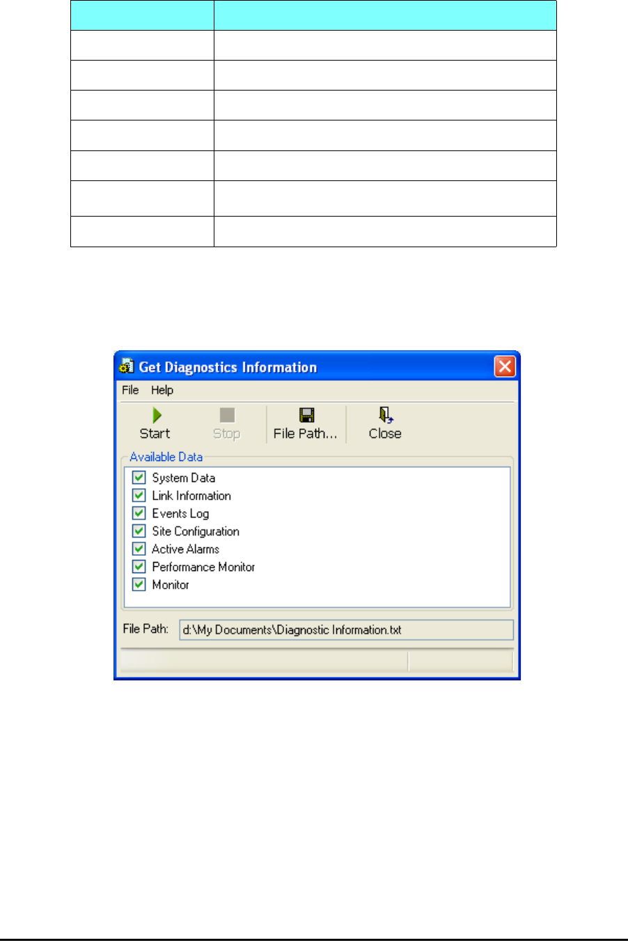
¾To get diagnostics
1. On the Help menu, choose Get Diagnostic Information.
Figure 7-1: Get Diagnostics Dialog Box
2. Select or deselect the data options. If the file is to be sent to RADWIN
Customer Support leave all options checked.
3. Click File Path to specify the folder in which you want to save the file
and then click Start to save the information.
The file is saved in the specified folder as Diagnostics Informa-
tion.txt
Table 7-1: Get Diagnostics Data and Description
Data Description
System Data General information about the system
Link Information Information about the link properties
Events Log List of recent system events
Site Configuration Data about the site parameters
Active Alarms List of active alarms
Performance Monitor Network performance data over defined time periods
Monitor Detailed event data record

Link Compatibility Chapter 7
RADWIN 1000/2000 User Manual Version 2.5p-4 7-3
Link Compatibility
Link Compatibility indicates the version compatibility using software traps.
As new hardware or software is added to existing networks compatibility
issues may arise. An incompatibility issue is indicated to the user by a
change of color of the Link Status box on the Main Menu screen. Trap mes-
sages in the events Log indicate the problems or limitations and suggest
upgrades when appropriate.
The following Link Status messages are given:
fullCompatibility - different software versions were detected that are fully
compatible. The message indicates that an upgrade is available.
restrictedCompatibility - different software versions were detected that
operate correctly. However, new features are not supported
softwareUpgradeRequired - different software versions were detected allow-
ing limited operation. The message is, that a software upgrade required.
versionsIncompatibility - different software versions were detected that are
incompatible. You need to perform local upgrades.
Reinstalling and Realigning a Link
It may be necessary to reinstall the link if the ODUs need to be realigned.
Table 7-2: Link Compatibility Trap Messages
Link State Link State
text
Link
Status
Color
Site
Description
Site
Desc.
Color
Link Status
Color
fullCompatibility Active Green SW Upgrade
Available Yellow Green
restrictedCompatibility Active - SW
Version mis-
match
Magenta
(Same as
authen-
tication
error)
SW Upgrade
Recommended Yellow Magenta
(Same as
authentication
error)
softwareUpgradeRequired Active – SW
Upgrade
Required
Brown
(Major)
SW Upgrade
Required Yellow Brown (Major)
versionsIncompatibility Not Active -
SW
Upgrade
Required
Red Local SW
Upgrade
Required
Yellow Red
Note
Activating Install Mode causes both sites to go into install mode, causing
disruption in service for approximately fifteen seconds.

The Link Budget Calculator Chapter 7
RADWIN 1000/2000 User Manual Version 2.5p-4 7-4
¾To reinstall the link:
1. Choose a site.
The Configuration dialog box opens.
2. In the Configuration dialog box, click the Install Mode button.
A message box asking if you want to enter install mode appears.
3. Click Yes to continue.
The system enters Install mode and the alignment tone becomes audi-
ble.
4. Realign the ODUs and start the Installation wizard (see chapter 4).
The Link Budget Calculator
The Link Budget Calculator is part of the RADWIN Manager software and is
found in the Help menu. This useful utility enables you to calculate the
expected performance of the wireless link and the possible configurations
for a specific link range including antenna size, cable loss and climate condi-
tions. For full details, see appendix D.
Performance Monitoring
RADWIN 1000/2000 Performance Monitoring constantly monitors traffic
over the radio link and collects statistics data for the air interface and Ether-
net ports. It does so continuously, even when the RADWIN Manager is not
connected.
Two types of logs are recorded:
•Monitor Log that records statistics on traffic rate and radio signal
strength.
•Events Log that records when the rates fall above or below a pre-
defined threshold.
Both the statistics Monitor log and events log can be saved as TXT files.
The Monitor Log
The Monitor Log records performance statistics for predefined intervals. You
can save the monitor log to a text file, as well as display the information in
an on-screen report.
Saving the Monitor Log
You can save the recorded Monitor Log statistics to a text file.
¾To save the monitor log:
1. From the Tools menu, choose Preferences.
The Preferences dialog box appears:
The Monitor Log Chapter 7
RADWIN 1000/2000 User Manual Version 2.5p-4 7-5
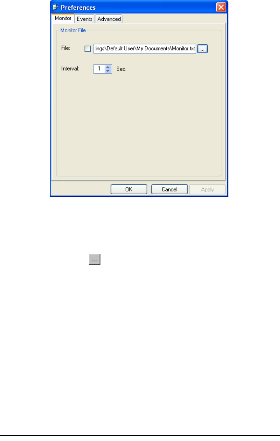
Figure 7-2: Preferences dialog box
2. Click the Monitor Tab.
3. Select the file to save.
4. Click the check box to open the file for saving.
5. Click the button and in the Select File dialog box indicate in which
folder and under what name the monitor log file is to be saved.
6. Set the time interval for adding data to the file.
7. Click OK to save the file.
Viewing Performance Reports
The Performance Monitor Report displays performance views of each of the
interfaces1.
¾To obtain performance monitoring reports:
1. From the main menu, choose Tools | Performance Monitoring
Report ...
You are presented with the following window:
1. Ethernet performance is not collected from PoE devices.
The Monitor Log Chapter 7
RADWIN 1000/2000 User Manual Version 2.5p-4 7-6
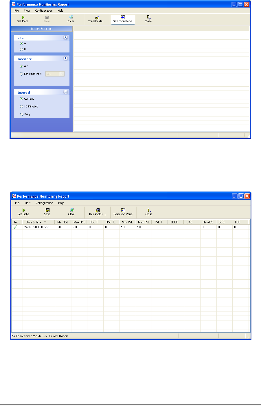
Figure 7-3: Basic Performance Monitoring Report
2. Choose a report type from the left panel and click the Get Data toolbar
button. For example, if you choose Site A, Air and Current, you will be
offered a report looking like this:
Figure 7-4: A typical Performance Monitoring Report
You can click the Selection Pane icon to toggle the side panel on or off.
The other reports look similar. Here is a detailed description of the reports
and their fields:

The Monitor Log Chapter 7
RADWIN 1000/2000 User Manual Version 2.5p-4 7-7
Several performance data occurrences are collected for each of the inter-
faces (ES, SES, and UAS), as well as Specific data per Interface type (e.g.,
TX and RX bytes for Ethernet). For the Air Interface, user defined thresholds
data are collected. Refer to table 7-3 and table 7-4, in Performance
Monitoring Report Toolbar below.
Data is collected and selectively displayed based on three time intervals as
selected by the Interval radio buttons:
• Current (t=0)
• 15 minutes Intervals
• Daily

The Monitor Log Chapter 7
RADWIN 1000/2000 User Manual Version 2.5p-4 7-8
Table 7-3: Explanation of performance data
Data type Reported Value Explanation
Generic PM Data
UAS – Unavailable
Seconds Seconds in which the interface was out of service.
ES – Errored Sec-
onds The number of seconds in which there was at least
one error block. Note that the notation of an error
block is different per interface.
SES – Severe Errored
Seconds The number of seconds in which the service quality
was low (the quality is different per type of inter-
face and determined by the BBER threshold per
interface).
BBE – Background
Block Error The number of errored blocks in an interval.
Integrity A flag indicating that the data was valid. Note that
the Performance Monitoring data is not valid if not
all the values were stored (e.g., due to clock
changes within the interval or power up reset).
Air Interface PM
Data
Max RSL The maximum of the receive signal level (mea-
sured in dBm).
Min RSL The minimum of the receive signal level (measured
in dBm).
Max TSL The maximum of the transmit signal level (mea-
sured in dBm).
Min TSL The minimum of the transmit signal level (mea-
sured in dBm).
RSL Threshold 1 The number of seconds in which the RSL was
below the specified threshold.
RSL Threshold 2 The number of seconds in which the RSL was
below the specified threshold.
TSL Threshold The number of seconds in which the RSL was
above the specified threshold.
BBER Threshold The BBER Threshold value counts the number of
seconds in which the Background Block Error Ratio
(BBER) exceeded the specified threshold.
Ethernet Interface
PM Data
Received Bytes The number of Megabytes received at the specified
port within the interval
Transmitted Bytes The number of Megabytes transmitted at the spec-
ified port within the interval.
The Monitor Log Chapter 7
RADWIN 1000/2000 User Manual Version 2.5p-4 7-9
Performance Monitoring Report Toolbar
You can use the toolbar to perform the actions described in the following
table:
Setting Air Interface Thresholds
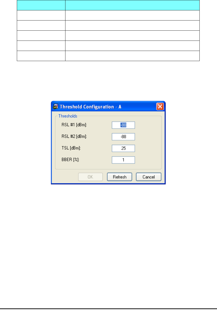
Use the Thresholds button on the Monitoring Performance Report toolbar to
set the Air Interface Thresholds:
Figure 7-5: Threshold configuration dialog box
BBER Threshold
This parameter counts the seconds during which the radio performance is
below a user specified threshold. The threshold is measured as a percent-
age. The threshold can be set from 0.1% up to 50%.
For links with Ethernet only service, 8% threshold is recommended. If there
are no problems during the interval, then for that threshold, the recom-
mended BBER value should be 0. Since the system provides a lossless
Ethernet service, there is throughput degradation in case of interference.
The degradation is proportional to the BBER.
RSL Threshold
RSL Threshold can also be used as an indicator of problems in the radio
channel. You can check the RSS by from the Link Budget Calculator results
Table 7-4: Action of the toolbar buttons
Command Button Action
Get Data Gathers current performance monitoring data.
Save Save current performance monitoring data to a file
Clear Clear current performance monitoring data.
Thresholds Set Air Interface Thresholds
Close Closes the active alarm window.
The Events Log Chapter 7
RADWIN 1000/2000 User Manual Version 2.5p-4 7-10
during installation. A value of -5dB from the current RSS is recommended as
a threshold.
The Events Log
The Events Log records system failures, loss of synchronization, loss of sig-
nal, compatibility problems and other fault conditions and events.
Alarms (traps) are displayed in the Events Log in the lower panel of the
main window. The Events Log may be saved as a text file.
The Events Log includes the following fields:
⇒Sequential number (ID)
⇒Date and time stamp
⇒Message
⇒Trap source
⇒IP address of the ODU that initiated alarm.
For complete information about traps and alarms see appendix F, MIB Ref-
erence, table F-3.
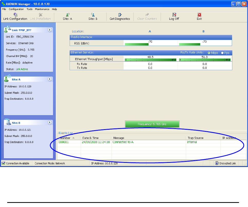
The events are displayed in the Events Log in the lower part of the RADWIN
Manager main window:
Figure 7-6: Events Log Display

RADWIN Manager Traps Chapter 7
RADWIN 1000/2000 User Manual Version 2.5p-4 7-11
RADWIN Manager Traps
The RADWIN Manager application issues traps to indicate various events,
displayed in the Wvents Log.
Table 7-5: RADWIN Manager Trap Messages
Trap Message Severity Remarks
Error loading trap catcher. Port 162 is already in use. Warning NMS will not catch any
traps from target, some
other application has
grabbed this port
Device unreachable! Error Check connectivity to target
Connected to <site_name> Information
<site_name> Site will be reset. Information
Restore Factory Default Settings in process on Site
<site_name> Information
Factory Settings: The process was not finished due to
connection issues. Warning Factory setting failed due to
connectivity problem to tar-
get
Reset: The process was not finished due to connec-
tion issues. Warning Factory setting failed due to
connectivity problem to tar-
get - Target will not be reset
Cannot Write to Monitor file. There is not enough
space on the disk. Warning Free some space on disk
and retry
Windows Error: <error_ID>. Cannot Write to Monitor
file. Warning Operating System error
TDM Counters were cleared for both sides Information
Identical IP addresses at <local_site_name> and
<remote_site_name> Warning Set up a different IP to each
site
The Product is not identified at the
<local_site_name> site. Warning NMS is incompatible with
the target release
The Product is not identified at the
<remote_site_name> site. Warning
The Product is not identified at both sites. Warning
Product Not Identified! Warning
The Manager identified a newer ODU release at the
<remote_site_name> site. Warning ODU release is newer than
NMS release. Wizards are
not available. NMS will be
used just for monitoring.
Upgrade the NMS. (You will
get this message as a pop
up)
The Manager identified a newer ODU release at both
sites. Warning
RADWIN Manager Traps Chapter 7
RADWIN 1000/2000 User Manual Version 2.5p-4 7-12
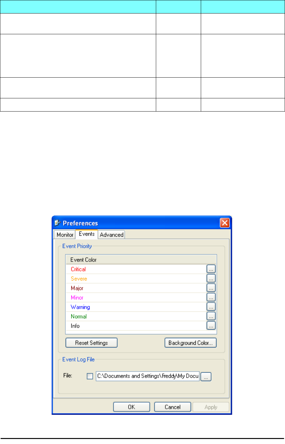
Setting the Events Preferences
You can define a color for the traps to be displayed in the Event Log win-
dow, according to the severity of the event. The severity is predefined.
¾To set the trap color:
1. From the Tools menu, choose Preferences.
The Preferences dialog box appears.
2. Click the Events Tab:
Figure 7-7: Preferences dialog box
The Manager identified a newer ODU release at the
<local_site_name> site. Warning
Newer Version identified at the <local_site_name>
site. Warning ODU release is newer than
NMS release. Wizards are
not available. NMS will be
used just for monitoring.
Upgrade the NMS
Newer Version identified at the <remote_site_name>
site. Warning
Newer Version Identified! Warning
Table 7-5: RADWIN Manager Trap Messages
Trap Message Severity Remarks

RADWIN Manager Traps Chapter 7
RADWIN 1000/2000 User Manual Version 2.5p-4 7-13
3. Select the event type and click on the button.
A color chart opens.
4. Select the desired color.
5. Repeat for all of the event types.
¾To set the trap background color:
• Click Background Color to change the text background.
¾To reset the event colors:
• Click Reset Settings to return to the default color settings.
Saving the Events Log
You can save recorded events in an Events Log text file. New alarms are
automatically added to the text file, as they enter the Events Log.
¾To save the Events Log:
1. From the Tools menu, choose Preferences.
The Preferences dialog box appears
2. Click the Events Tab.
3. Select the file to save.
4. Click the check box to open the file for saving.
Click the button and in the Select File dialog box indicate in which folder
and under what name the Events Log file is to be saved, and click OK.
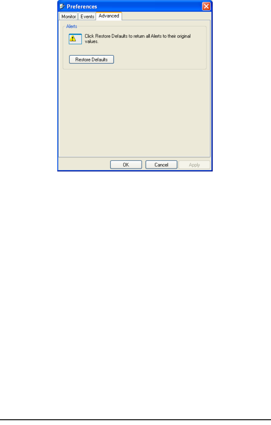
Reverting Alarm Messages
Alarm messages can be reverted to their default values by choosing the
Advanced tab from the Preferences dialog:
Note
To store the Events Log, first define the IP address, subnet mask, default
gateway and trap address of the managing computer (see Configuring
the ODU Address on page 6-4 for details).
RADWIN Manager Traps Chapter 7
RADWIN 1000/2000 User Manual Version 2.5p-4 7-14
Just click the Restore Defaults button, followed by OK.
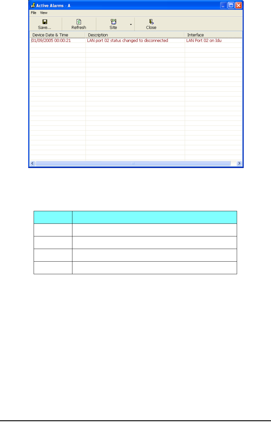
Active Alarms
Upon setting a trap destination, applicable events are reported as active
alarms to the user. The active alarms are saved and can be viewed in the
Active Alarms window.
¾To view summary of saved alarms:
• From the Tools menu, choose Active Alarm Summary.
The Active Alarms Summary window opens:
RADWIN Manager Traps Chapter 7
RADWIN 1000/2000 User Manual Version 2.5p-4 7-15
Figure 7-8: Active Alarms Summary
The following table provides an explanation of the command buttons
Remote Power Fail Indication
Remote power fail indication indicates to one side that the other side has
had a power failure. The failed site sends a final trap indication about the
power loss just before powering off.
A “Dying-Gasp” circuit identifies the power failure at a minimum interval of
20 milliseconds before the ODU or IDU powers off. During that interval a
message notifying the power failure is sent to Site B. Alarm output number
4 indicates power failure at Site B.
Table 7-6: Active Alarms command buttons
Command Action
Save Saves the alarms in CSV or text format for further analysis.
Refresh Reads the alarms from the ODU.
Site Selects site for the active alarms.
Close Closes the active alarm window.

Troubleshooting Chapter 7
RADWIN 1000/2000 User Manual Version 2.5p-4 7-16
Troubleshooting
Use the following table to troubleshoot LED fault indications:
Use the following table to troubleshoot faults in the system:.
Replacing an ODU
Prior to any action ensure that both ODUs have the same software version.
You can see this on the inventory panels for each site.
For Site A, click Site A | Inventory and note the ODU software version.
Repeat this for Site B using Site B | Inventory.
If either ODU has an old software version, perform a software upgrade. It is
important to configure the new ODU exactly the same as the old ODU to
avoid configuration mismatches, which will disrupt the link.
An ODU may be reconfigured in several ways.
• Use the backup Configuration
If a backup of the configuration is available, restore that configura-
tion using Site A| Restore.
Table 7-7: LED fault indicators
LED Status Remedy
PWR Off Check that AC adapter is connected to the IDU-E and the AC
power outlet.
IDU Orange Check that the IDU/ODU cable is properly wired and connected.
ODU Red Check that the IDU/ODU cable is properly wired and connected.
AIR I/F Orange Complete the installation procedure from the management soft-
ware.
Red Check the ODU Antenna alignment. Check that the radio configu-
ration of both site A and site B units are the same (channel and
Link ID).
SVC Off
Table 7-8: Troubleshooting
Symptom Remedy
No power Ensure that power is connected to the IDU.
Ensure that the ODU cable is properly wired and connected.
No signal Complete the installation procedure from the RADWIN Manager
Check the ODU alignment. Check that the radio configuration of both site A
and site B units are the same (channel and Link ID.
Weak signal
received Check the ODU alignment, reconfigure the link.
Check the alignment tone sounds the Best Signal sequence.
Restoring Factory Setup Chapter 7
RADWIN 1000/2000 User Manual Version 2.5p-4 7-17
• Manual Configuration
The new ODU can be configured manually according to the link con-
figuration. Remember to use the same settings for Link ID, chan-
nels, link password, IP addresses, and names.
Restoring Factory Setup
¾To restore factory setup:
1. Set the remaining ODUs back to the factory setup by using the Site A
|Advanced option.
2. Activate the second ODU and carry out a new Installation.
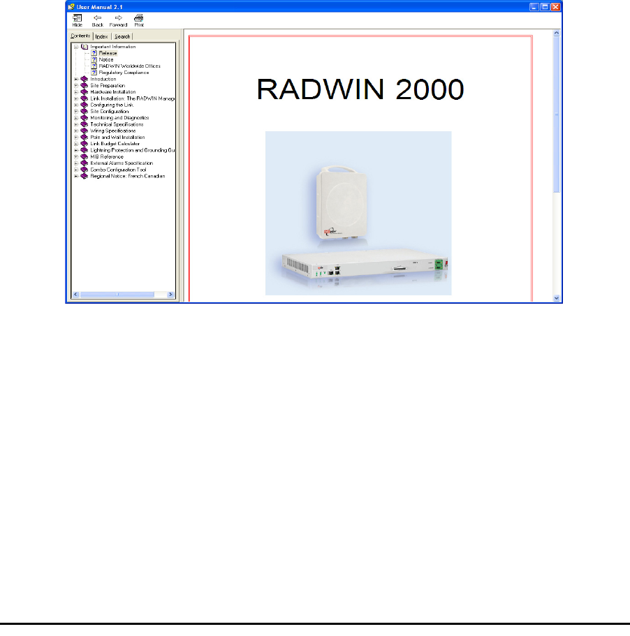
Online Help
Online help can be accessed from the Help menu on the main screen of the
RADWIN 1000/2000 Manager.
Figure 7-9: Online Help for RADWIN 1000/2000
Customer Support
Customer support for this product can be obtained from the local VAR, Inte-
grator or distributor from whom it was purchased.
For further information, please contact the RADWIN 1000/2000 distributor
nearest to you or one of RADWIN's offices worldwide (see RADWIN
Worldwide Offices at the beginning of this manual).