Radwin RW2058U Outdoor radio unit operating in 5.8 GHz bands User Manual STW
Radwin Ltd. Outdoor radio unit operating in 5.8 GHz bands STW
Radwin >
Contents
Manual
UM 5000-2530/04.11
RADWIN 1000/2000/5000
Broadband Wireless
Transmission System
User Manual
Version 2.5.30p3

RADWIN 1000/2000/5000 User ManualVersion 2.5.30p3 i
RADWIN 1000/2000/5000
User Manual
Notice
This manual contains information that is proprietary to RADWIN Ltd. (RADWIN hereafter). No
part of this publication may be reproduced in any form whatsoever without prior written
approval by RADWIN.
Right, title and interest, all information, copyrights, patents, know-how, trade secrets and
other intellectual property or other proprietary rights relating to this manual and to the
RADWIN products and any software components contained therein are proprietary products
of RADWIN protected under international copyright law and shall be and remain solely with
RADWIN.
The RADWIN name is a registered trademark of RADWIN Ltd. No right, license, or interest to
such trademark is granted hereunder, and you agree that no such right, license, or interest
shall be asserted by you with respect to such trademark.
You shall not copy, reverse compile or reverse assemble all or any portion of the User Manual
or any other RADWIN documentation or products. You are prohibited from, and shall not,
directly or indirectly, develop, market, distribute, license, or sell any product that supports
substantially similar functionality based or derived in any way from RADWIN products.Your
undertaking in this paragraph shall survive the termination of this Agreement.
This Agreement is effective upon your opening of a RADWIN product package and shall
continue until terminated. RADWIN may terminate this Agreement upon the breach by you of
any term thereof. Upon such termination by RADWIN, you agree to return to RADWIN any
RADWIN products and documentation and all copies and portions thereof.
For further information contact RADWIN at the address below or contact your local
distributor.
Disclaimer
The parameters quoted in this document must be specifically confirmed in writing before they
become applicable to any particular order or contract. RADWIN reserves the right to make
alterations or amendments to the detail specification at its discretion. The publication of
information in this document does not imply freedom from patent or other rights of RADWIN,
or others.

RADWIN 1000/2000/5000 User ManualVersion 2.5.30p3 ii
RADWIN Worldwide Offices
For technical support contact: support@radwin.com
For technical support in India only, contact: support-india@radwnin.com
For sales support contact: sales@radwin.com
Website: www.radwin.com
Corporate Headquarters
27 Habarzel Street
Tel Aviv, 69710
Israel
Tel: +972 3 766 2917
Support Headquarter
27 Habarzel Street
Tel Aviv, 69710
Israel
Tel: +972 3 766 2900
Mobile: +972 54 766 0044
RADWIN North America
900 Corporate Drive
Mahwah, NJ 07430
USA
Tel (1): 1 800 444 7234 / 341
Tel (2): +1 201 529 1100 / 341
Latin America Headquarters
Rua Grao Mogol 828
Belo Horizonte, MG 30310-010
Brazil
Tel (1): +55 31 919 76 402
Tel (2): +972 54 758 6808
India Headquarters
Mohan Co-operative Industrial Estate
E-13, B-1 Extn
New Delhi, 110044
India
Tel: +91 11 4053 9180
APAC Headquarters
1 Jalan Kuala #13-01
The Morningside, 239639
Singapore
Tel: +65 9878 3004
Indonesia Sales Office
Jl. Jenderal Sudirman Kav. 86
Jakarta, 10220
Indonesia
Tel: +62 8138 570 0657
Philippines Sales Office
37A. A luna St. West Rembo
Makati City, 1200
Philippines
Tel: +63 2882 6886
Mobile: +63 91 789 23427
China Sales Office
Asian Games Village
Huiyuan Gongyu J1312
Beijing 100101
China
Tel: +86 010 8498 0629

RADWIN 1000/2000/5000 User ManualVersion 2.5.30p3 iii
Regulatory Compliance
General Note
This system has achieved Type Approval in various countries around the world. This means
that the system has been tested against various local technical regulations and found to
comply. The frequency bands in which the system operates may be “unlicensed” and in these
bands, the system can be used provided it does not cause interference.
FCC/IC - Compliance
This equipment has been tested and found to comply with the limits for a Class B digital
device, pursuant to Part 15 of the FCC Rules and ICES-003 of IC. These limits are designed to
provide reasonable protection against harmful interference in a residential installation. This
equipment generates, uses and can radiate radio frequency energy and, if not installed and
used in accordance with the instructions, may cause harmful interference to radio
communications. However, there is no guarantee that interference will not occur in a
particular installation. If this equipment does cause harmful interference to radio or television
reception, which can be determined by turning the equipment off and on, the user is
encouraged to try to correct the interference by one or more of the following measures:
• Reorient or relocate the receiving antenna.
• Increase the separation between the equipment and receiver.
• Connect the equipment into an outlet on a circuit different from that to which the
receiver is connected.
Consult the dealer or an experienced radio/TV technician for help.
Changes or modifications to this equipment not expressly approved by the party responsible
for compliance (RADWIN Ltd.) could void the user's authority to operate the equipment.
Warning
It is the responsibility of the installer to ensure that when using the outdoor
antenna kits in the United States (or where FCC rules apply), only those
antennas certified with the product are used. The use of any antenna other
than those certified with the product is expressly forbidden in accordance to
FCC rules CFR47 part 15.204.
Caution
In accordance to IC standard RSS-Gen - To reduce potential radio
interference to other users, the antenna type and its gain should be so
chosen that the equivalent isotropically radiated power (e.i.r.p) is not more
than that permitted for successful communication
Caution
Outdoor units and antennas should be installed ONLY by experienced
installation professionals who are familiar with local building and safety
codes and, wherever applicable, are licensed by the appropriate government
regulatory authorities. Failure to do so may void the product warranty and
may expose the end user or the service provider to legal and financial
liabilities. Resellers or distributors of this equipment are not liable for injury,
damage or violation of regulations associated with the installation of outdoor
units or antennas. The installer should configure the output power level of
antennas according to country regulations and antenna type.

RADWIN 1000/2000/5000 User ManualVersion 2.5.30p3 iv
Indoor Units comply with part 15 of the FCC rules and ICES-003 standard. Operation is
subject to the following two conditions:
(1) These devices may not cause harmful interference.
(2) These devices must accept any interference received, including interference that may
cause undesired operation.
Canadian Emission Requirements for Indoor Units
This Class B digital apparatus complies with Canadian ICES-003.
Cet appareil numẻrique de la classe B est conforme ả la norme NMB-003 du Canada.
Safety Practices
Applicable requirements of National Electrical Code (NEC), NFPA 70; and the National
Electrical Safety Code, ANSI/IEEE C2, must be considered during installation.
NOTES:
1. A Primary Protector is not required to protect the exposed wiring as long as the exposed
wiring length is limited to less than or equal to 140 feet, and instructions are provided to
avoid exposure of wiring to accidental contact with lightning and power conductors in
accordance with NEC Sections 725-54 (c) and 800-30.
In all other cases, an appropriate Listed Primary Protector must be provided. Refer to Articles
800 and 810 of the NEC for details.
2. For protection of ODU against direct lightning strikes, appropriate requirements of NFPA
780 should be considered in addition to NEC.
3. For Canada, appropriate requirements of Section 60 of the CEC 22.1should be considered
as applicable.
4. E1/T1 ports are intended for connection to indoor lines only and are not exposed to
outdoor plants.
Warning
The antenna used for this transmitter must be installed to provide a
separation distance of at least 225cm from all persons and must not be co-
located or operated in conjunction with any other antenna or transmitter.
Warning
This product was tested with special accessories - indoor unit (IDU or
PoE), FTP Cat 5e shielded cable with sealing gasket, 12 AWG grounding
cable - which must be used with the unit to insure compliance.

RADWIN 1000/2000/5000 User ManualVersion 2.5.30p3 v
Table of Contents
Notice....................................................................................................................... i
RADWIN Worldwide Offices.................................................................................... ii
Regulatory Compliance..............................................................................................iii
Chapter 1 Introduction
Welcome! .............................................................................................................. 1-1
Key Applications..................................................................................................... 1-2
WiMAX and IP Backhaul..............................................................................1-2
Broadband Access.......................................................................................1-2
Private Networks ........................................................................................1-3
Key Features of RADWIN 1000/2000/5000............................................................... 1-3
RADWIN 1000/2000/5000 Link................................................................................ 1-5
The Radio Outdoor Unit (ODU) ...................................................................1-6
The Indoor Units (IDU)...............................................................................1-8
IDU-C.........................................................................................................................1-8
IDU-E.........................................................................................................................1-9
Power Over Ethernet (PoE) Devices ...........................................................1-9
Antennas...................................................................................................1-10
Flat Panel Antennas...................................................................................................1-11
Parabolic Dish Antennas.............................................................................................1-12
RADWIN Manager.....................................................................................1-12
Accessories................................................................................................1-13
Documentation set supplied with RADWIN 1000/2000/5000.................1-13
How to Use this Manual........................................................................................ 1-14
A Little Terminology ............................................................................................. 1-14
Conventions Used in this Manual ........................................................................... 1-16
Notifications..............................................................................................1-16
Typographical conventions.......................................................................1-16
General ....................................................................................................................1-16
Software...................................................................................................................1-16
Windows Terminology ..............................................................................1-17
Chapter 2 Site Preparation
Planning the Link Site............................................................................................. 2-1
Overview.....................................................................................................2-1
The Site Survey...................................................................................................... 2-1
Introduction................................................................................................2-1
Recommended Equipment..........................................................................2-1
Stage 1: Preliminary Survey .................................................................................... 2-2
Stage 2: Physical Survey......................................................................................... 2-3
Additional Outdoor Site Requirements.......................................................2-4
Additional Indoor Site Requirements .........................................................2-4
Stage 3: RF Survey................................................................................................. 2-4
Chapter 3 Hardware Installation
Safety Practices...................................................................................................... 3-1
Preventing overexposure to RF energy ......................................................3-1
Grounding ...................................................................................................3-1
Protection against Lightning.......................................................................3-2
General........................................................................................................3-2
Package Contents................................................................................................... 3-2
ODU Package Contents ...............................................................................3-2
IDU Package Contents................................................................................3-4
External Antenna Package Contents...........................................................3-5
Additional Tools and Materials Required................................................................... 3-5
Tools and Materials.....................................................................................3-5
Cables and connectors................................................................................3-5
Hardware Installation Sequence .............................................................................. 3-5
Outdoor installation................................................................................................ 3-6
Mounting the ODU.......................................................................................3-6

RADWIN 1000/2000/5000 User ManualVersion 2.5.30p3 vi
Mounting external antennas.......................................................................3-7
Mounting the Lightning Protection Devices................................................3-7
Outdoor Connections ..................................................................................3-8
Indoor Installation.................................................................................................. 3-8
IDU-E Installation........................................................................................................3-8
Mounting the IDU-C....................................................................................3-8
Connecting power to the IDU ...................................................................3-11
Connecting the ODU to the IDU................................................................3-12
Installing a Link using PoE Devices ..........................................................3-12
Connecting User Equipment......................................................................3-12
Connecting and Aligning ODUs / Antennas ............................................................. 3-13
Chapter 4 Link Installation: The RADWIN Manager
Installing theRADWIN Manager Application .............................................................. 4-1
Minimum System Requirements.................................................................4-1
Installing the Software...............................................................................4-1
Starting the RADWIN Manager................................................................................ 4-2
Login Errors........................................................................................................... 4-5
Unsupported Device....................................................................................4-5
Incorrect IP Address...................................................................................4-6
Incorrect Password.....................................................................................4-6
Continuing without an IP Address............................................................................ 4-6
Changing the Log On Password ..................................................................4-7
Installing the Link: First steps.................................................................................. 4-7
Default Settings ..........................................................................................4-9
Front Panel LEDs on the IDU-C...................................................................4-9
Installation Menu and Toolbar Functionality............................................4-10
Installing the Link: Overview................................................................................. 4-13
Installing the Link: Step 1, Start the Wizard ........................................................... 4-14
Installing the Link: Step 2, System Parameters....................................................... 4-14
Changing the Link Password.....................................................................4-16
Installing the Link: Step 3, Channel Settings........................................................... 4-17
Installing the Link: Step 4, Tx Power and Antenna Settings ..................................... 4-19
General......................................................................................................4-20
Dual Antennas at Both Sites .....................................................................4-20
Single Antennas at Both Sites...................................................................4-21
Single and Dual Antennas.........................................................................4-21
Considerations for Changing Antenna Parameters...................................4-22
Installing the Link: Step 5, Services ....................................................................... 4-25
Installing the Link: Step 6, Installation Summary and Exit ....................................... 4-26
Chapter 5 Configuring the Link
Link Configuration: Getting Started.......................................................................... 5-1
The Main Window of the RADWIN Manager...............................................5-1
The RADWIN Manager Toolbar...................................................................5-2
The RADWIN Manager Main Menu..............................................................5-3
Elements of the RADWIN Manager Main Window ......................................5-6
Configuring the Link: Overview.............................................................................. 5-10
Configuring the Link: Step 1, Start the Wizard........................................................ 5-11
Configuring the Link: Step 2, System Parameters.................................................... 5-11
Configuring the Link: Step 3, Channel Settings ....................................................... 5-12
Configuring the Link: Step 4, Tx Power and Antenna Settings.................................. 5-18
Configuring the Link: Step 5, Services.................................................................... 5-20
Configuring the Link: Step 6, Configuration Summary and Exit................................. 5-21
Chapter 6 Site Configuration
Configuring the Site................................................................................................ 6-1
Editing the Configuration Parameters by Site ............................................6-1
Functions on the left of the dialog box:.........................................................................6-2
Functions at the top of the dialog box:..........................................................................6-2
Viewing Air Interface Details ................................................................................... 6-3
Changing the Transmit Power ................................................................................. 6-4

RADWIN 1000/2000/5000 User ManualVersion 2.5.30p3 vii
Site Management: IP Address and VLAN .................................................................. 6-4
Configuring the ODU Address .....................................................................6-4
Configuring VLAN Settings..........................................................................6-5
Lost or forgotten VLAN ID............................................................................................6-7
Setting the Date and Time ...................................................................................... 6-7
Ethernet Properties................................................................................................. 6-9
Configuring the Bridge................................................................................6-9
ODU Mode................................................................................................................6-10
IDU Aging time .........................................................................................................6-10
Configuring Ethernet Ports Mode .............................................................6-11
Setting the Maximum Information Rate...................................................6-12
Displaying the Inventory....................................................................................... 6-12
Security Features ................................................................................................. 6-13
Changing the Link Password.....................................................................6-14
RADWIN Manager Community Strings .....................................................6-14
Editing Community Strings.........................................................................................6-15
Forgotten Community string.......................................................................................6-16
Muting the alignment tone.................................................................................... 6-17
Setting External Alarm Inputs................................................................................ 6-17
Managing Configuration Files................................................................................. 6-18
Backup Configuration to a File..................................................................6-18
Restoring a Configuration File ..................................................................6-19
Resetting...................................................................................................6-19
Configuration with Telnet...................................................................................... 6-20
Chapter 7 Monitoring and Diagnostics
Retrieving Link Information (Get Diagnostics)........................................................... 7-1
Link Compatibility................................................................................................... 7-3
Reinstalling and Realigning a Link............................................................................ 7-3
The Link Budget Calculator ..................................................................................... 7-4
Performance Monitoring.......................................................................................... 7-4
The Monitor Log..........................................................................................7-4
Saving the Monitor Log................................................................................................7-4
Viewing Performance Reports.......................................................................................7-5
Performance Monitoring Report Toolbar........................................................................7-9
Setting Air Interface Thresholds ...................................................................................7-9
The Events Log..........................................................................................7-10
RADWIN Manager Traps ...........................................................................7-11
Setting the Events Preferences...................................................................................7-12
Saving the Events Log ...............................................................................................7-13
Reverting Alarm Messages .........................................................................................7-14
Active Alarms............................................................................................................7-14
Remote Power Fail Indication.....................................................................................7-15
Troubleshooting................................................................................................... 7-16
Replacing an ODU ................................................................................................ 7-16
Restoring Factory Setup........................................................................................ 7-17
Online Help.......................................................................................................... 7-17
Customer Support ................................................................................................ 7-17
Appendix A Technical Specifications
Configuration........................................................................................................ A-1
Radio ................................................................................................................... A-2
Ethernet Interface................................................................................................. A-4
Management......................................................................................................... A-5
Mechanical............................................................................................................ A-5
Power................................................................................................................... A-5
Environmental....................................................................................................... A-5
Safety................................................................................................................... A-5
EMC ..................................................................................................................... A-5
Air Interface.......................................................................................................... A-5
Appendix B Wiring Specifications
ODU-IDU Cable..................................................................................................... B-1

RADWIN 1000/2000/5000 User ManualVersion 2.5.30p3 viii
User Port Connectors............................................................................................ B-1
LAN Port......................................................................................................B-1
IDU-C Alarm Connector ..............................................................................B-3
Appendix C Pole and Wall Installation
ODU Mounting Kit Contents.................................................................................... C-1
Mounting RADWIN 1000/2000/5000 on a pole......................................................... C-2
Mounting RADWIN 1000/2000/5000 on a Wall......................................................... C-3
Mounting an External Antenna ............................................................................... C-3
Appendix D Link Budget Calculator
Overview.............................................................................................................. D-1
User Input.................................................................................................. D-1
Link Budget Calculator Internal Data ........................................................ D-1
Calculations .......................................................................................................... D-2
EIRP ........................................................................................................... D-2
Expected RSS and Fade Margin.................................................................. D-2
Min and Max Range.................................................................................... D-2
Service ....................................................................................................... D-2
Availability ................................................................................................. D-2
Antenna Height.......................................................................................... D-3
Running the Link Budget Calculator ........................................................................ D-3
About the Fresnel Zone........................................................................................ D-13
Appendix E Lightning Protection and Grounding Guidelines
Grounding for Antenna Cable ................................................................................. E-1
Grounding for Indoor/Outdoor Units ....................................................................... E-2
ODU Grounding...........................................................................................E-2
IDU Grounding............................................................................................E-2
External Lightning Surge Suppressors and Grounding............................................... E-3
Internal ESD Protection circuits .............................................................................. E-7
Appendix F MIB Reference
Introduction........................................................................................................... F-1
About the MIB.............................................................................................F-1
Terminology................................................................................................F-1
Interface API ......................................................................................................... F-1
Control Method ...........................................................................................F-1
Community String.......................................................................................F-2
Private MIB Structure.............................................................................................. F-2
MIB Parameters ..................................................................................................... F-4
Supported Variables from the RFC 1213 MIB.............................................F-4
MIB Parameters..........................................................................................F-5
MIB Traps............................................................................................................ F-18
General......................................................................................................F-18
Trap parameters........................................................................................F-18
RADWIN Manager Traps ...........................................................................F-21
Appendix G External Alarms Specification
External Alarms Specification.................................................................................. G-1
Appendix H Combo Configuration Tool
What is the Combo Configuration Tool? .................................................................. H-1
Who may use the Combo Configuration Tool........................................................... H-1
Caveat to the use of the Combo Configuration Tool ................................................. H-1
Prerequisites to using the Combo Configuration Tool................................................ H-2
Operating the Combo Configuration Tool................................................................. H-2
Before using the Combo Configuration Tool............................................................. H-2
Using the Combo Configuration Tool....................................................................... H-2
If you receive an error message............................................................................. H-6
Appendix I Regional Notice: French Canadian
Procédures de sécurité............................................................................................ I-1
Généralités.................................................................................................. I-1
Mise à la terre ............................................................................................. I-1

RADWIN 1000/2000/5000 User ManualVersion 2.5.30p3 ix
Protection contre la foudre......................................................................... I-2
Précautions de sécurité pendant le montage de ODU ................................ I-2
Connecter la terre à IDU-C ......................................................................... I-3
Installation sur pylône et mur.................................................................................. I-4
Contenu du kit de montage ODU ................................................................ I-4
Montage sur un pylône ............................................................................... I-5
Montage sur un mur.................................................................................... I-6
Montage d'une antenne externe................................................................. I-7
Contenu du kit de montage d'une antenne externe ................................... I-7
Index

RADWIN 1000/2000/5000 User ManualVersion 2.5.30p3 x
List of Figures
FIGURE 1-1 TYPICAL WIMAX AND IP BACKHAUL APPLICATION ....................................................1-2
FIGURE 1-2 TYPICAL BROADBAND ACCESS APPLICATION ...........................................................1-3
FIGURE 1-3 PRIVATE NETWORK..........................................................................................1-3
FIGURE 1-4 EXAMPLE OF LINK ARCHITECTURE - SYSTEM COMPONENTS ........................................1-6
FIGURE 1-5 ODU FORM FACTORS.......................................................................................1-7
FIGURE 1-6 IDU-C FRONT PANEL.......................................................................................1-9
FIGURE 1-7 IDU-E - FRONT VIEW.......................................................................................1-9
FIGURE 1-8 IDU-E: REAR PANEL........................................................................................1-9
FIGURE 1-9 POE DEVICE - SHOWING THE RADIO ETHERNET PORT.............................................1-10
FIGURE 1-10 ODU WITH INTEGRATED FLAT PANEL ANTENNA...................................................1-10
FIGURE 1-11 FLAT PANEL ANTENNA ..................................................................................1-11
FIGURE 1-12 EXTERNAL ANTENNAS - PARABOLIC DISH...........................................................1-12
FIGURE 1-13 RADWIN MANAGER SCREEN..........................................................................1-13
FIGURE 1-14 SITE CONFIGURATION WINDOW WITH OPEN MANAGEMENT PANEL............................1-18
FIGURE 3-1 ODU MOUNTING KIT .......................................................................................3-3
FIGURE 3-2 CONNECTORIZED ODU - FRONT AND REAR VIEWS...................................................3-3
FIGURE 3-3 INTEGRATED ODU - FRONT AND REAR VIEWS ........................................................3-4
FIGURE 3-4 IDU-C PACKAGE CONTENTS - THE IDU-C.............................................................3-4
FIGURE 3-5 IDU-C PACKAGE CONTENTS - THE MOUNTING KIT AND DC POWER PLUGS .....................3-4
FIGURE 3-6 TYPICAL INSTALLATION DIAGRAM (WITH EXTERNAL ANTENNA)....................................3-6
FIGURE 3-7 NEW STYLE IDU-E: REAR PANEL ........................................................................3-8
FIGURE 3-8 IDU-C FRONT PANEL .......................................................................................3-9
FIGURE 3-9 IDU-C - A PERSPECTIVE VIEW ...........................................................................3-9
FIGURE 3-10 IDU-C LEDS.............................................................................................3-10
FIGURE 3-11 DU-C OWER CONNECTORS.............................................................................3-12
FIGURE 3-12 BEEP SEQUENCE FOR ANTENNA ALIGNMENT........................................................3-14
FIGURE 4-1 LAN PORTS ON THE FRONT PANEL OF THE IDU-C...................................................4-2
FIGURE 4-2 PINGING AN UNINSTALLED AND UNCONFIGURED LINK................................................4-3
FIGURE 4-3 LOGIN SCREEN ...............................................................................................4-3
FIGURE 4-4 LOGIN SCREEN WITH COMMUNITY OPTIONS VISIBLE.................................................4-5
FIGURE 4-5 UNSUPPORTED DEVICE MESSAGE..........................................................................4-5
FIGURE 4-6 UNREACHABLE DEVICE MESSAGE..........................................................................4-6
FIGURE 4-7 OPENING RADWIN MANAGER WINDOW PRIOR TO INSTALLATION ...............................4-8
FIGURE 4-8 IDU-C FRONT PANEL LEDS.............................................................................4-10
FIGURE 4-9 LINK INSTALLATION WIZARD............................................................................4-14
FIGURE 4-10 : INSTALLATION WIZARD, SYSTEM DIALOG BOX ..................................................4-15
FIGURE 4-11 CHANGE LINK PASSWORD DIALOG BOX..............................................................4-16
FIGURE 4-12 LOST OR FORGOTTEN LINK PASSWORD RECOVERY................................................4-17
FIGURE 4-13 CHANNEL SETTINGS - AUTOMATIC CHANNEL SELECTION........................................4-18
FIGURE 4-14 CHANNEL SETTINGS - SHOWING AVAILABLE INSTALLATION RATES ............................4-19
FIGURE 4-15 TRANSMISSION POWER AND ANTENNA PARAMETERS.............................................4-20
FIGURE 4-16 ANTENNA CONFIGURATION DIALOG WITH OPENED TYPE SELECTION .........................4-23
FIGURE 4-17 ANTENNA PARAMETERS CHANGE WARNING..........................................................4-24
FIGURE 4-18 TX POWER LIMITS.......................................................................................4-24
FIGURE 4-19 SERVICES AND RATES DIALOG.........................................................................4-25
FIGURE 4-20 INSTALLATION WIZARD EXIT SUMMARY.............................................................4-26
FIGURE 4-21 MAIN WINDOW OF THE MANAGER AFTER INSTALLATION.........................................4-27
FIGURE 5-1 MAIN WINDOW, WIRELESS LINK IS ACTIVE...........................................................5-2
FIGURE 5-2 ETHERNET BANDWIDTH INDICATION ....................................................................5-8
FIGURE 5-3 LINK CONFIGURATION WIZARD.........................................................................5-11
FIGURE 5-4 CONFIGURATION WIZARD, SYSTEM DIALOG BOX....................................................5-12
FIGURE 5-5 CHANNEL SETTINGS DIALOG BOX - AUTOMATIC CHANNEL SELECTION.........................5-13
FIGURE 5-6 SEARCHING FOR THE BEST OPERATING CHANNEL ...................................................5-14
FIGURE 5-7 CHANNEL SETTINGS WITHOUT AUTOMATIC CHANNEL SELECTION................................5-15
FIGURE 5-8 CHANNEL FREQUENCY OPTIONS.........................................................................5-16
FIGURE 5-9 CHOOSING AN “OTHER” OPERATING CHANNEL FREQUENCY......................................5-17
FIGURE 5-10 TRANSMISSION POWER AND ANTENNA PARAMETERS.............................................5-18

RADWIN 1000/2000/5000 User ManualVersion 2.5.30p3 xi
FIGURE 5-11 ANTENNA CONFIGURATION DIALOG WITH OPENED TYPE SELECTION .........................5-19
FIGURE 5-12 SERVICES AND RATES DIALOG.........................................................................5-20
FIGURE 5-13 CONFIGURATION WIZARD EXIT SUMMARY..........................................................5-21
FIGURE 5-14 MAIN WINDOW OF THE MANAGER AFTER CONFIGURATION ......................................5-22
FIGURE 6-1 CONFIGURATION DIALOG BOX ............................................................................6-2
FIGURE 6-2 AIR INTERFACE DETAILS....................................................................................6-3
FIGURE 6-3 CHANGING THE TRANSMIT POWER.......................................................................6-4
FIGURE 6-4 MANAGEMENT ADDRESSES - SITE CONFIGURATION DIALOG BOX..................................6-5
FIGURE 6-5 CONFIGURING MANAGEMENT TRAFFIC VLAN SETTINGS .............................................6-6
FIGURE 6-6 DATE AND TIME CONFIGURATION........................................................................6-8
FIGURE 6-7 CHANGE DATE AND TIME ..................................................................................6-8
FIGURE 6-8 DATE AND TIME CONFIGURED FROM AN NTP SERVER...............................................6-9
FIGURE 6-9 BRIDGE CONFIGURATION - SITE CONFIGURATION DIALOG BOX .................................6-10
FIGURE 6-10 INVENTORY SCREEN .....................................................................................6-13
FIGURE 6-11 AVAILABLE SECURITY FEATURES.......................................................................6-14
FIGURE 6-12 CHANGING THE COMMUNITY STRING................................................................6-16
FIGURE 6-13 ALTERNATIVE COMMUNITY DIALOG BOX ............................................................6-17
FIGURE 6-14 EXTERNAL ALARM CONFIGURATION ..................................................................6-18
FIGURE 6-15 TELNET MANAGEMENT SCREEN .......................................................................6-22
FIGURE 7-1 GET DIAGNOSTICS DIALOG BOX .........................................................................7-2
FIGURE 7-2 PREFERENCES DIALOG BOX.................................................................................7-5
FIGURE 7-3 BASIC PERFORMANCE MONITORING REPORT ..........................................................7-6
FIGURE 7-4 A TYPICAL PERFORMANCE MONITORING REPORT.....................................................7-6
FIGURE 7-5 THRESHOLD CONFIGURATION DIALOG BOX .............................................................7-9
FIGURE 7-6 EVENTS LOG DISPLAY.....................................................................................7-10
FIGURE 7-7 PREFERENCES DIALOG BOX...............................................................................7-13
FIGURE 7-8 ACTIVE ALARMS SUMMARY ..............................................................................7-15
FIGURE 7-9 ONLINE HELP FOR RADWIN 1000/2000/5000..................................................7-17
FIGURE B-1 EXAMPLE FOR CONNECTING THE ALARM CONNECTOR................................................ B-4
FIGURE C-4 MOUNTING ON A POLE..................................................................................... C-2
FIGURE C-5 MOUNTING ON A WALL ................................................................................... C-3
FIGURE D-1 ACCESSING THE LINK BUDGET CALCULATOR .........................................................D-4
FIGURE D-2 LINK BUDGET SCREEN..................................................................................... D-5
FIGURE D-3 PRODUCT SELECTOR ....................................................................................... D-7
FIGURE D-4 RATE SELECTOR.............................................................................................D-8
FIGURE D-5 CALCULATION OF DISTANCE FROM SITE COORDINATES............................................D-9
FIGURE D-6 CLIMACTIC C FACTORS.................................................................................. D-10
FIGURE D-7 CLIMACTIC C FACTOR DESCRIPTION ................................................................. D-11
FIGURE D-8 WORLD MAP SHOWING C FACTOR CONTOURS ..................................................... D-12
FIGURE D-9 FRESNEL ZONE ............................................................................................ D-13
FIGURE E-1 GROUNDING ANTENNA CABLES........................................................................... E-2
FIGURE E-2 GROUNDING A TYPICAL POLE INSTALLATION.......................................................... E-3
FIGURE E-3 GROUNDING A TYPICAL WALL INSTALLATION.......................................................... E-4
FIGURE E-4 ODU SURGE SUPPRESSOR AND GROUNDING.......................................................... E-4
FIGURE E-5 TRANSTECTOR’S SURGE SUPPRESSOR .................................................................. E-5
FIGURE E-6 SURGE SUPPRESSOR AND GROUNDING AT BUILDING ENTRY POINT............................... E-7
FIGURE F-1 TOP LEVEL SECTIONS OF THE PRIVATE MIB...........................................................F-3
FIGURE I-4 MONTAGE SUR UN PYLÔNE ................................................................................. I-5
FIGURE I-5 MONTAGE SUR UN MUR ..................................................................................... I-6

RADWIN 1000/2000/5000 User ManualVersion 2.5.30p3 xii
List of Tables
TABLE 1-1 AVAILABLE ODU PRODUCTS - RELEASE 2.5.30P3 ....................................................1-8
TABLE 1-2 RELEASE 2.1 IDU-C PRODUCTS...........................................................................1-8
TABLE 3-1 COMPONENTS OF AN IDU-C FRONT PANEL............................................................3-10
TABLE 3-2 IDU-C FRONT PANEL LEDS..............................................................................3-11
TABLE 4-1 PC REQUIREMENTS FOR THE RADWIN MANAGER APPLICATION...................................4-1
TABLE 4-2 RADWIN MANAGER: OFFLINE FUNCTIONALITY........................................................4-7
TABLE 4-3 DEFAULT SETTINGS...........................................................................................4-9
TABLE 4-4 FRONT PANEL LEDS........................................................................................4-10
TABLE 4-5 RADWIN MANAGER MAIN MENU FUNCTIONALITY ...................................................4-11
TABLE 4-6 RADWIN MANAGER TOOLBAR..........................................................................4-12
TABLE 4-7 LINK INSTALLATION WIZARD .............................................................................4-13
TABLE 4-8 RADWIN 1000/2000/5000 TRANSMISSION RATES...............................................4-22
TABLE 5-1 RADWIN MANAGER TOOLBAR............................................................................5-3
TABLE 5-2 RADWIN MANAGER MAIN MENU FUNCTIONALITY .....................................................5-4
TABLE 5-3 LINK DETAILS..................................................................................................5-6
TABLE 5-4 LINK SITE DETAILS, SITE A AND SITE B.................................................................5-7
TABLE 5-5 STATUS BAR INDICATORS....................................................................................5-9
TABLE 5-6 LINK CONFIGURATION WIZARD ..........................................................................5-10
TABLE 6-1 ODU MODE CONFIGURATION FOR COMMON...........................................................6-11
TABLE 6-2 TELNET COMMANDS.........................................................................................6-20
TABLE 7-1 GET DIAGNOSTICS DATA AND DESCRIPTION............................................................7-2
TABLE 7-2 LINK COMPATIBILITY TRAP MESSAGES ...................................................................7-3
TABLE 7-3 EXPLANATION OF PERFORMANCE DATA....................................................................7-8
TABLE 7-4 ACTION OF THE TOOLBAR BUTTONS.......................................................................7-9
TABLE 7-5 RADWIN MANAGER TRAP MESSAGES..................................................................7-11
TABLE 7-6 ACTIVE ALARMS COMMAND BUTTONS ...................................................................7-15
TABLE 7-7 LED FAULT INDICATORS...................................................................................7-16
TABLE 7-8 TROUBLESHOOTING.........................................................................................7-16
TABLE B-1 ODU-IDU CONNECTOR PINOUT.......................................................................... B-1
TABLE B-2 FAST ETHERNET CONNECTOR PINOUT................................................................... B-2
TABLE B-3 IDU-C ALARM CONNECTOR (DRY-CONTACT) ......................................................... B-3
TABLE B-4 TERMINAL BLOCK 3-PIN -48VDC........................................................................ B-4
TABLE C-1 BILL OF MATERIALS: ODU MOUNTING KIT............................................................. C-1
TABLE F-1 SUPPORTED RFC 1213 VARIABLES .......................................................................F-4
TABLE F-2 PRIVATE MIB PARAMETERS.................................................................................F-5
TABLE F-3 MIB TRAPS...................................................................................................F-18
TABLE G-1 OUTPUT ALARMS PINOUT.................................................................................. G-1

RADWIN 1000/2000/5000 User ManualVersion 2.5.30p3 1-1
Chapter 1
Introduction
Welcome!
Welcome to the RADWIN 1000/2000/5000 radio series, designed for the IP
and WiMAX Backhaul, Private Networks and Broadband Access global mar-
kets. The RADWIN 1000/2000/5000 series is an innovation in high-capacity
carrier-grade sub-6GHz radios, and designed to meet the requirements of
current and next-generation markets and applications. RADWIN 1000/2000/
5000 also features software configurable antenna port activation enabling
single (RADWIN 1000) or dual (RADWIN 2000) antenna port operation. The
RADWIN 5000 series is identifier for software configured Point to Multipoint
devices. The device configured as RADWIN 2000 has an advanced air-inter-
face based on MIMO, antenna diversity.
The RADWIN 1000/2000 radio series offers unmatched performance and
carrier-class quality with the following features:
• Superior spectral efficiency at 5, 10, 20MHz and 40MHz channels in
the 5.3, 5.4 and 5.8 GHz spectrum bands.
• High Ethernet capacity (up to 270Mbps at 40MHz channel band-
width.)
• Combo frequency products for maximum flexibility
• Advanced air-interface based on MIMO, built-in diversity and OFDM
technologies
• Superior range performance
• Simple installation and management
• High Tx power
The RADWIN 1000/2000 radio series supports the 2.4, 4.9, 5.3, 5.4 and 5.8
GHz spectrum bands, and complies with international standards and regula-
tions (FCC, IC Canada). The 5.8 GHz spectrum band complies with FCC rule
47 CFR Part 15 subparts C and E.
The RADWIN 5000 radio series supports 4.9, 5.3, 5.4 and 5.8 GHz spectrum
bands, and complies with international standards and regulations (FCC, IC
Canada). The 5.8 GHz spectrum band complies with FCC rule 47 CFR Part
15 subparts C and E.

Key Applications Chapter 1
RADWIN 1000/2000/5000 User ManualVersion 2.5.30p3 1-2
The model RADWIN 1000 RW-1020-0150 / RADWIN 2000 RW-2020-0150
supports the 2.4GHz band and complies with FCC and IC standards.
The RADWIN 1000 3GHz Band / RADWIN 2000 3GHz Band / RADWIN 5000
3GHz Band support the 3.5 and 3.65 GHz spectrum bands and comply with
FCC and IC standards.
Key Applications
WiMAX and IP Backhaul
The RADWIN 1000/2000/5000 radio series offers WiMAX operators and ISPs
a unique, highly scalable and cost-effective backhaul solution. Designed to
suit a wide range of topologies, RADWIN 1000/2000/5000 is easy to install
and maintain, enabling operators to quickly and efficiently expand their net-
works and introduce new services to a growing subscriber base.
Figure 1-1: Typical Wimax and IP Backhaul application
Broadband Access
With RADWIN 1000/2000/5000, service providers can quickly and efficiently
expand their networks, and provide high-capacity services that meet the
increasing demand for high-quality, high-speed broadband.

Private Networks Chapter 1
RADWIN 1000/2000/5000 User ManualVersion 2.5.30p3 1-3
Figure 1-2: Typical Broadband Access application
Private Networks
RADWIN 1000/2000/5000 is the ultimate solution for private networks such
as enterprises, education, government and utility organizations that wish to
own and manage their own networks and eliminate the costly recurring
charges from service providers.
RADWIN 1000/2000/5000's cost-effective solution enables a variety of orga-
nizations to connect geographically dispersed sites at ranges of up to 80km
(50 miles).
Figure 1-3: Private Network
Key Features of RADWIN 1000/2000/5000
Some of the outstanding features of the RADWIN 1000/2000/5000 radio
series are as follows:
High Capacity
The RADWIN 1000/2000 system provides a high-capacity link of up
to 270Mbps at 40MHz channel bandwidth.
Superior Spectral Efficiency

Key Features of RADWIN 1000/2000/5000 Chapter 1
RADWIN 1000/2000/5000 User ManualVersion 2.5.30p3 1-4
Built on advanced MIMO and OFDM technologies, the RADWIN
1000/2000 system provides a high-capacity link at channel band-
width of 40MHz. This channel bandwidth supports high robustness
of the air interface under interference and harsh conditions. In coun-
tries where applicable, narrow channel bandwidth reduces the cost
of the spectrum license.
Advanced Air Interface
The RADWIN 1000/2000/5000 system provides an advanced air-
interface based on MIMO, built-in diversity and OFDM technologies,
resulting in an exceptionally robust air interface.
Using the following technologies, the RADWIN 1000/2000/5000 air
interface is designed to ensure nonstop, high quality transmission,
even under interference and harsh conditions:
• Automatic Adaptive Rate (AAR) is a mechanism that dynami-
cally adapts the air interface rate by changing both the signal
modulation and coding.
• Automatic Channel Selection (ACS) chooses the best channel by
monitoring the available radio channels and dynamically select-
ing a channel which is best suited for transmission at any given
time.
• Automatic Repeat Request (ARQ) is a mechanism for error con-
trol during data transmission. When the receiver detects an
error in the received information, it automatically requests the
transmitter to resend the information. This process is repeated
until the transmission is error free or the error continues
beyond a predetermined number of maximum transmissions.
RADWIN 1000/2000/5000's ARQ mechanism is optimized for
time-critical traffic.
• Forward Error Correction (FEC) with very low overhead and
algorithms specifically designed for the varying conditions of
license-exempt frequency bands, ensuring fast, robust and
error-free communications.
High transmission (Tx) power of 29.95dBm
The RADWIN 1000/2000/5000 system supports high Tx power, com-
pliant with radio regulations. High Tx power increases the system's
availability and range, and enables the high performance with
smaller antennas, thus reducing the total cost of the solution (lower
CAPEX), installation and tower rent costs (lower OPEX).
Superior range performance
The RADWIN 1000/2000/5000 system supports high capacity at
superior ranges. The Link Budget Calculator (appendix D) is used to
determine the capacity and range according to the choice of prod-
uct, antenna, type of service and environmental conditions.
Simple installation and management
RADWIN 1000/2000/5000 systems are extremely simple to install
and maintain. They are typically up and running in less than an hour.

RADWIN 1000/2000/5000 Link Chapter 1
RADWIN 1000/2000/5000 User ManualVersion 2.5.30p3 1-5
The RADWIN Manager application has full local and remote manage-
ment capabilities. The user-friendly SNMP based management tool
provides full end-to-end configuration, event logging, and perfor-
mance monitoring capabilities.
Enhanced Security
The security features of RADWIN 1000/2000/5000 include:
• RADWIN 1000/2000/5000's AES 128-bit integrated advanced
encryption support provides enhanced air interface security for
carriers and private networks. It ensures user data protection
with one of the most sophisticated commercially available com-
bined encryption and authentication techniques, CCM/AES. This
technique combines message authentication (preventing anti-
spoofing and replay protection) with commercial encryption,
and complies with the IEEE 802.11i (phase iii) security recom-
mendations.
CCM/AES uses a symmetric 128-bit encryption key (EK), and a
nonce, and provides both message encryption and authenticat-
ing signature. The nonce mechanism enables the receiver to
remember already received genuine messages and reject all
replayed messages.
• Initial encryption and authentication is based on a user-defined
master key (Link Password). While standard Wireless LAN
encrypts only the Ethernet Payload, the AES encrypts both the
source and destination MAC addresses.
• In addition to normal login access, Read or Write Community
access is available at login
RADWIN 1000/2000/5000 Link
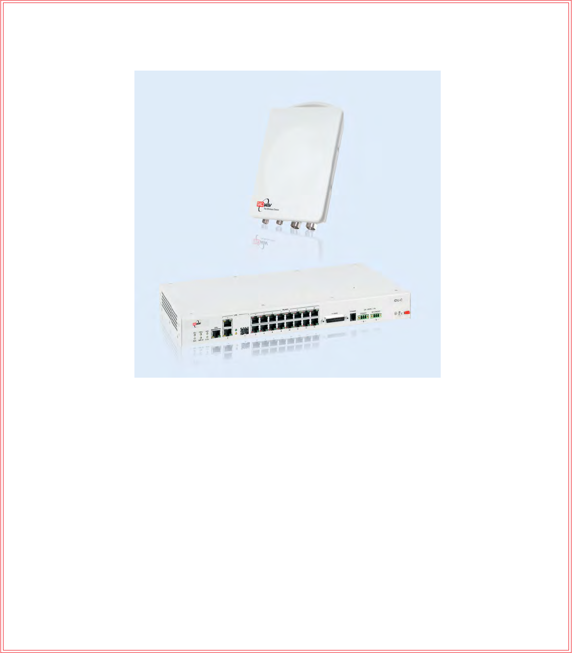
The RADWIN 1000/2000 point-to-point solution is a wireless communication
link. RADWIN 5000 is a point-to-multipoint topology solution. Typically each
side of the link is comprised of an Outdoor Unit (ODU) and antenna and an
Indoor Unit (IDU) or PoE device as shown in figure 1-4 below.
The link is managed by the SNMP-based RADWIN Manager application.
The IDU and the ODU are connected by a CAT5e cable that carries the ser-
vice traffic and power.

The Radio Outdoor Unit (ODU) Chapter 1
RADWIN 1000/2000/5000 User ManualVersion 2.5.30p3 1-6
Figure 1-4: Example of Link Architecture - System Components
The Radio Outdoor Unit (ODU)
The ODU is the radio transceiver of the RADWIN 1000/2000/5000 system.
It supports two radios for MIMO operation. It is available with an integrated
antenna (Integrated Antenna ODU) or with connectors for an external
antenna (Connectorized ODU).
The ODU may be mounted on a pole or a wall, and connects to the IDU or
PoE device using a CAT5e cable.
The Radio Outdoor Unit (ODU) Chapter 1
RADWIN 1000/2000/5000 User ManualVersion 2.5.30p3 1-7
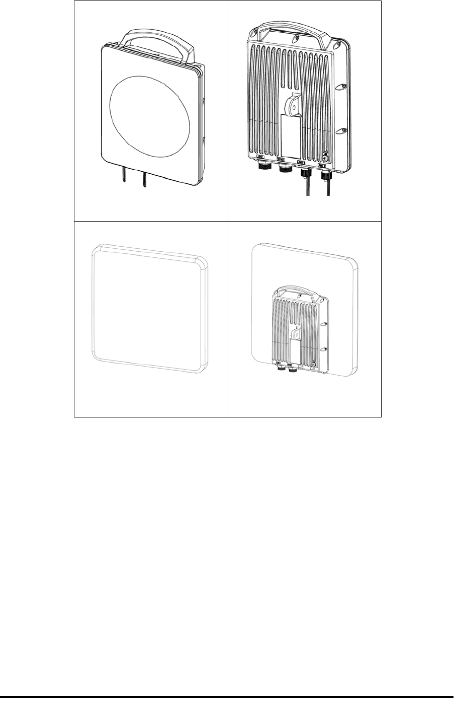
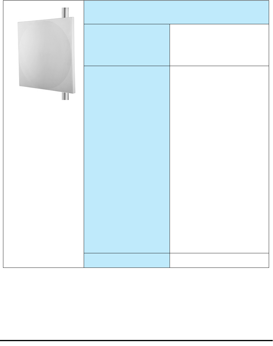
The ODU comes in two form factors as shown in figure 1-5 below:
Figure 1-5: ODU Form Factors
• Integrated Antenna ODU
This ODU has an integrated 370mm (1.2ft) flat panel antenna, with
a gain of 23dBi. The ODU contains both the radio and the antenna
as a single unit housed in a weatherproof case.
• Connectorized ODU
This ODU has 2x N-type connectors for connecting an external
antenna.
a. Connectorized ODU - Front b. Connectorized ODU - Rear
c. Integrated Antenna ODU -
Front d. Integrated Antenna ODU -
Rear

The Indoor Units (IDU) Chapter 1
RADWIN 1000/2000/5000 User ManualVersion 2.5.30p3 1-8
The ODU products available in release 2.5.30p3 are shown below:
The only available external antenna is, single bipolar.
For further information, see page 4-20, Installing the Link: Step 4, Tx
Power and Antenna Settings.
The Indoor Units (IDU)
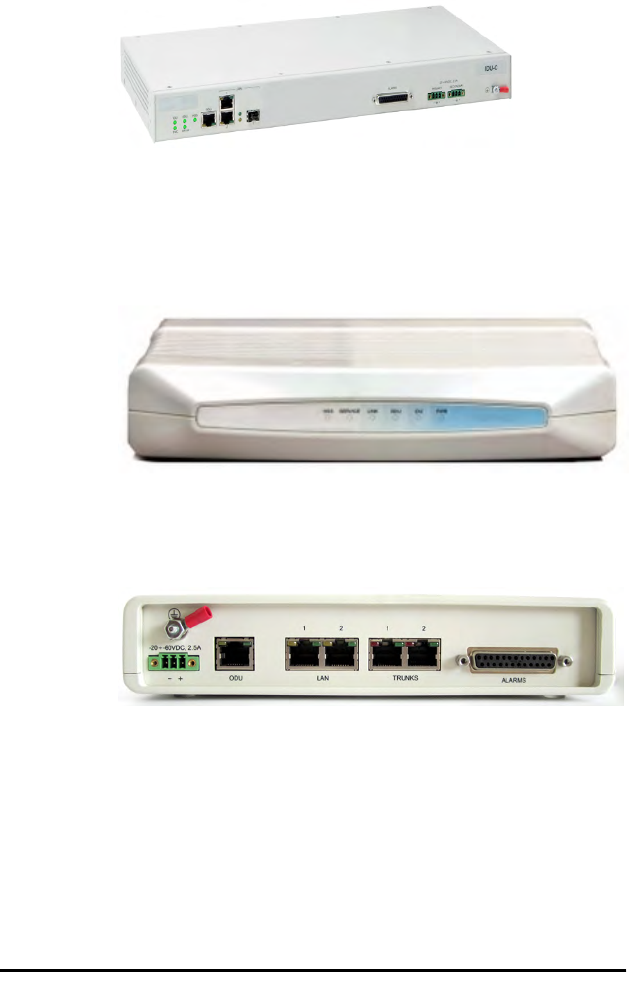
IDU-C
The IDU-C has the service ports and provides aggregation of these services
towards the ODU that transports them over the air. The IDU-C also provides
power to the ODU.
The IDU-C is a carrier-class 19 inch, 1U unit, providing two Ethernet ports,
dry contact alarms and indication LEDs. It has two DC power feed connec-
tors. An AC to DC converter is available for powering the IDU-C from an AC
source. The IDU-C is designed to be rack mounted.
One IDU-C product is available in release 2.5.30p3:
Table 1-1: Available ODU Products - Release 2.5.30p3
Part Number Description
Form Factor Frequency Bands and Regulations
RW-2050-0150
RW-5550-0150 Integrated antenna FCC/IC5.725 – 5.850 GHz
FCC/IC5.250 – 5.350 GHz
FCC/IC5.470 – 5.725 GHz
FCC/IC4.940 – 4.990 GHz
FCC/IC2.400 – 2.4835 GHz
RW-2050-0250 Connectorized for exter-
nal antenna (2x N-type)
RW-2020-0150
RW-1020-0150 Integrated and connector-
ized antenna (2x N-Type)
FCC/IC2.400 – 2.4835GHz
RW-1030 3 GHz BAND
RW-2030 3 GHz BAND
RW-2030 3 GHz BAND
FCC/IC3.650 – 3.700GHz
IC3.475 – 3.650GHz
RW-5200-0250
RW-5550-0250 Connectorized for exter-
nal antenna (2 x N-type)
FCC/IC5.725 – 5.850 GHz
FCC/IC5.250 – 5.350 GHz
FCC/IC5.470 – 5.725 GHz
FCC/IC 5.725 – 5.825 GHz
FCC/IC4.940 – 4.990 GHz
Table 1-2: Release 2.1 IDU-C Products
Part Number Ethernet
ports Power Form
factor
7200-2000 2Dual DC feed
-20 to -60VDC 19" 1U
Power Over Ethernet (PoE) Devices Chapter 1
RADWIN 1000/2000/5000 User ManualVersion 2.5.30p3 1-9
Figure 1-6: IDU-C Front Panel
IDU-E
The IDU-E is a carrier grade, compact, half 19 inch wide, 1U plastic unit,
providing up to two Ethernet ports and up to two E1/T1 interfaces. It offers
Layer 2 support for Ethernet service and HSS support for collocated links. It
is a low cost unit intended for both Access applications and Enterprise use.
Figure 1-7: IDU-E - front view
The IDU-E rear panel (right to left) has a 25 pin Dry Contact Alarms port.
the two (or no) trunk ports, two LAN ports, an ODU port and finally a 3 pin
DC power plug identical to that used on the IDU-C.
Figure 1-8: IDU-E: Rear panel
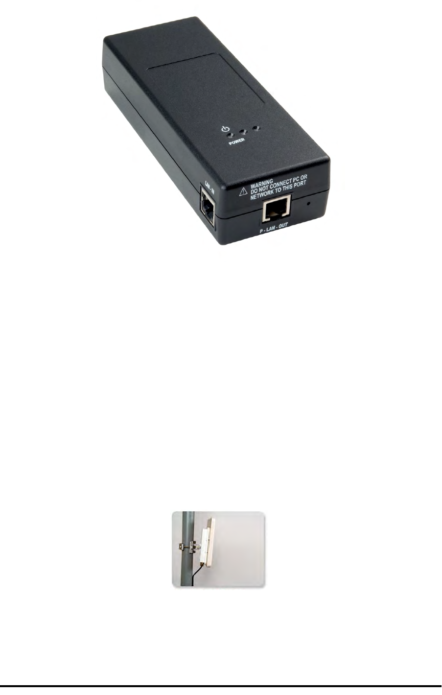
Power Over Ethernet (PoE) Devices
The PoE device provides Ethernet service only, with power for the ODU. The
PoE device is extremely compact, having only two Ethernet ports and a
standard 3 pin male AC power socket.
Antennas Chapter 1
RADWIN 1000/2000/5000 User ManualVersion 2.5.30p3 1-10
Figure 1-9: PoE device - showing the radio Ethernet port
Antennas
An antenna is the radiating and receiving element from which the radio sig-
nal, in the form of RF power, is radiated to its surroundings and vice versa.
The antenna gain and transmitting power may be limited by country regula-
tions.
The RADWIN 1000/2000/5000 may be operated with an integrated antenna
that is part of the ODU unit, or with external antennas connected to the
ODU via N-type connectors. All cables and connections must be connected
correctly to reduce RF losses. The required antenna impedance is 50Ω.
The Integrated Antenna ODU is provided with 370 mm (1.2ft) flat panel
antenna. The radio and the antenna are housed in a weatherproof case as a
single unit.
Figure 1-10: ODU with integrated Flat Panel antenna
External antennas are available for the RADWIN 1000/2000/5000 radios,
varying in operating frequencies, form factor, size and gain, dual or single
polarization.
Antennas Chapter 1
RADWIN 1000/2000/5000 User ManualVersion 2.5.30p3 1-11
The RADWIN 1000/2000 operating in frequency bands 5.3, 5.4, 5.8 GHz can
utilize external antennas with RF feeder cables that produce 6 dBi mi-nimal
assembly gain.
The RADWIN 1000 3GHz Band / RADWIN 2000 3GHz Band / RADWIN 5000
3GHz Band operating in the 3.5 and 3.65 GHz can utilize external antennas
with RF feeder cables that produce 13.5 dBi minimal assembly gain.
Flat Panel Antennas
The Flat Panel antenna shown in figure 1-11 below has an integrated or
external configuration:
Figure 1-11: Flat Panel Antenna
Integrated or External
1.2ft Flat Panel Dual Polarization
Frequency
4.9 – 6.0 GHz
2.4 – 2.7 GHz (Ext)
2.3 – 2.7 GHz (Int)
3.3 – 3.8 GHz (Int/Ext)
Gain
External
21 dBi at 4.9 – 5.0 GHz
22 dBi at 5.0 – 5.15 GHz
23 dBi at 5.15 – 6.0 GHz
20 dBi at 2.4 – 2.7 GHz
22 dBi at 3.3 – 3.8 GHz
14 dBi at 4.9 – 5.95 GHz
14.5 dBi at 4.9 – 4.95 GHz
15 dBi at 4.95 – 5.15 GHz
15.5 dBi at 5.15 – 5.47 GHz
16.5 dBi at 5.47 – 6.0 GHz
13.5 dBi at 6.0 – 6.06 GHz
Integrated
21 dBi at 4.9 – 5.0 GHz
22 dBi at 5.0 – 5.15 GHz
23.5 dBi at 5.15 – 5.725 GHz
24 dBi at 5.725 – 6.0 GHz
16.2 dBi at 2.3 – 2.4 GHz
17.5 dBi at 2.4 – 2.7 GHz
21 dBi at 3.3 – 3.8 GHz
Size 1.2 x 1.2 ft / 371x371 mm

RADWIN Manager Chapter 1
RADWIN 1000/2000/5000 User ManualVersion 2.5.30p3 1-12
Parabolic Dish Antennas
Figure 1-12: External Antennas - Parabolic Dish
See the RADWIN products catalog for RADWIN offering of external anten-
nas. External antennas are also available from authorized antenna vendors.
RADWIN Manager
The RADWIN Manager is an SNMP-based management application which
manages a complete link over a single IP address. It can also manage each
side of the link separately.
The RADWIN Manager application facilitates installation and configuration
of the link between the ODU units. The intuitive, easy-to-use RADWIN Man-
ager has a graphical Microsoft Windows interface, and can be run locally
and remotely.
The RADWIN Manager provides:
• Installation Wizard
• On-line monitoring of air interface quality allowing the administrator
to monitor the service and status of each link
• On-line monitoring of equipment alarms and QoS
• Local and remote loopback testing
• Configuration settings
• On-line user manual and help files
• Link Budget Calculator for calculating the expected performance of
the RADWIN 1000/2000/5000 wireless link and the possible service
configurations for a specific link range.
The RADWIN Manager can easily be integrated with any NMS system.
External
2ft Dish Dual Polarization
Frequency 5.150 - 5.875 GHz
4.900 – 5.850 GHz
3.300 – 3.800 GHz
Gain 28 dBi
25 dBi (3.5/3.65GHz)
Diameter 2 ft / 620 mm
Beam Width H,V: 5.6°
Accessories Chapter 1
RADWIN 1000/2000/5000 User ManualVersion 2.5.30p3 1-13
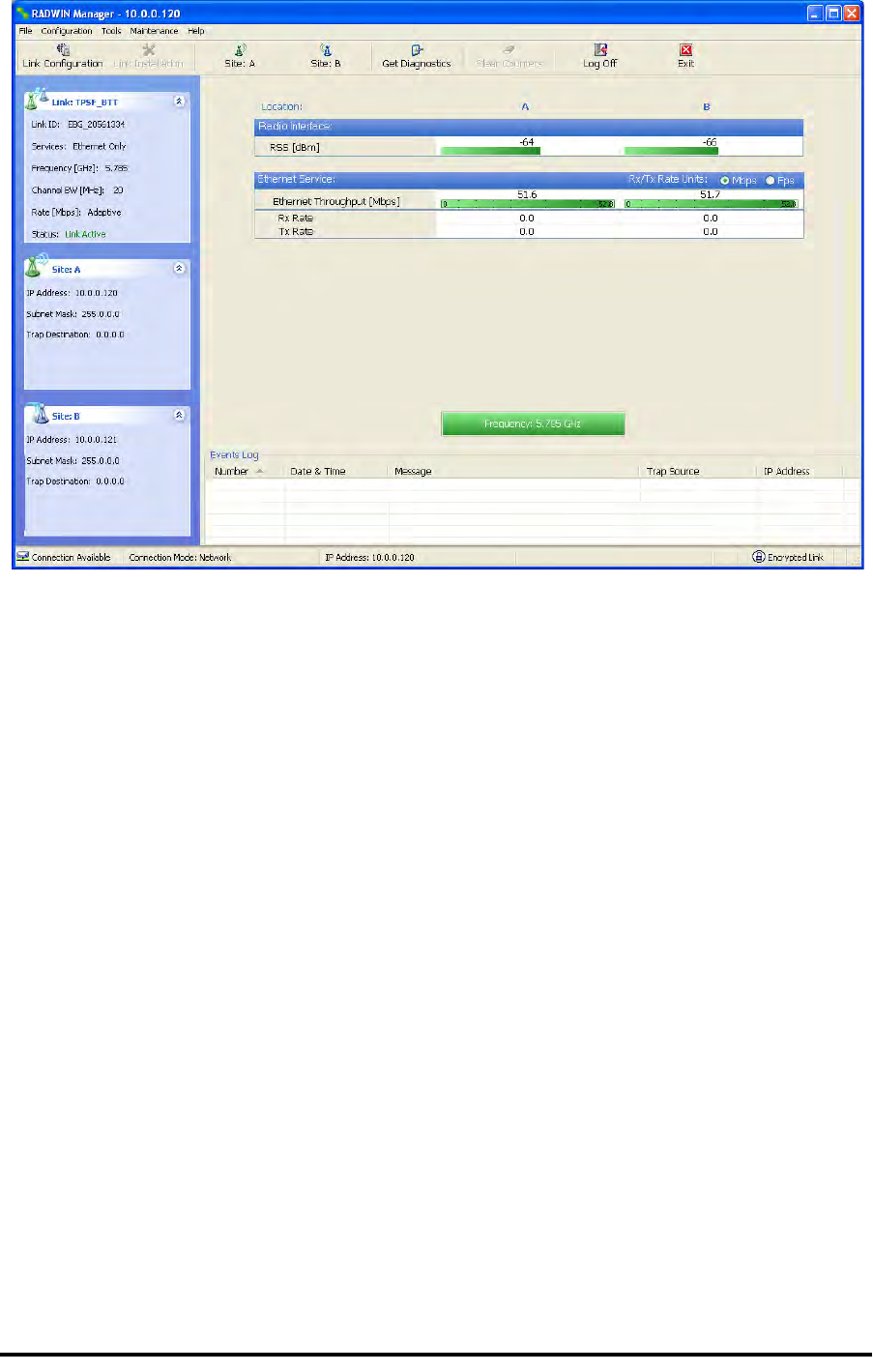
Figure 1-13: RADWIN Manager screen
Accessories
RADWIN provides a variety of accessories to support the RADWIN 1000/
2000/5000 system:
• PoE devices
• AC Power Adaptor
• External Lightning Protection Unit
• Cables to connect the various system elements
Documentation set supplied with RADWIN 1000/2000/
5000
The technical documentation supplied with a RADWIN 1000/2000/5000
includes the following items:
• A Quick Start Guide for experienced installers
• A full User Manual - the document which you are reading

How to Use this Manual Chapter 1
RADWIN 1000/2000/5000 User ManualVersion 2.5.30p3 1-14
How to Use this Manual
This User Manual is divided into functionally distinct chapters reflecting the
activities required to set up a RADWIN 1000/2000/5000. The division is
shown in the following table:
A Little Terminology
In the field, a link typically has a local or headquarters site as for example in
figure 1-2 above. Here the service provider is the local or headquarters
site. The service recipient is the remote site.
Where the link is completely internal to a corporation, the choice of the local
and remote is just a matter of convenience.
Chapter/
Appendix Subject Audience
2 Site Preparation Site survey team
3 Hardware Instal-
lation Field technician
4 Link Installation:
The RADWIN Man-
ager Installation technician
5 Configuring the
Link Installation technician, System manager
6 Site Configuration Installation technician, System manager
7 Monitoring and
Diagnostics Installation technician, System manager
A Technical Specifi-
cations Installation technician, System manager
B Wiring Specifica-
tions Installation technician
C Pole and Wall
Installation Installation technician
D Link Budget Cal-
culator Installation technician
E Lightning Protec-
tion and Ground-
ing Guidelines Field technician
F MIB Reference System manager
G External Alarms
Specification Installation technician, System manager,
Field technician
H Combo Configura-
tion Tool Installation technician

A Little Terminology Chapter 1
RADWIN 1000/2000/5000 User ManualVersion 2.5.30p3 1-15
A link then, consists of two sites.
In Broadband Wireless terminology, the local and remote sites are some-
times referred to as “near” and “far”, “HQ” and “remote” and so on.
The site which is closer to the network core (often the local site) will be
referred to as site A, and the opposite side of the link, usually closer to the
end user, as site B.
This choice is application-neutral and will be used throughout the manual
both to describe the sites and their names as in the examples.
The link is configured and managed using a PC, the managing computer
connected to site A. (The precise requirements for the managing computer
are set out in chapter 3, Hardware Installation).
RADWIN 1000/2000/5000 supports three connection methods for the man-
aging computer:
•Local - a direct peer to peer connection between the Ethernet ports
on the managing computer and the IDU or PoE device. Local con-
nection is always read-write.
•Network - the managing computer and the site A IDU or PoE
device belong to a LAN and communicate through a router or hub
•Over-the-air - the managing computer connects to site B via the
air interface
The managing computer may be connected to the link through an IDU or a
PoE device. In what follows, where ever we refer to an IDU it includes PoE
devices unless stated otherwise. Typically, if we need to refer to an IDU as
such, we will use a model name such as IDU-C.
Conventions Used in this Manual Chapter 1
RADWIN 1000/2000/5000 User ManualVersion 2.5.30p3 1-16
Conventions Used in this Manual
Notifications
Notifications consist of Notes, Cautions and Warnings.
Typographical conventions
General
Where a term is defined or introduced for the first time, it is shown in Bold-
face. You will have noticed this usage in the Terminology section above.
Software
The RADWIN Manager is a Microsoft Windows application following the user
interface conventions of familiar Microsoft Windows programs.
We would describe the chain of menu commands indicated in the following
screen shot, like this:
Tools|Active Alarms|1 A
Note
The purpose of a Note is to
• Draw your attention to something that may not be obvious or coun-
ter-intuitive
• Emphasize a special feature or peculiarity of the RADWIN 1000/2000/
5000
• Offer an external reference for additional information
• Add a caveat that would not qualify as a full Caution or Warning (see
below)
• Provide additional background to what follows
• Offer a recommendation
• Highlight an indication of something to watch out for
• Advise you if an action has “side effects” i.e. it may disturb something
else that would be best left undisturbed
• Remind you of something that should be kept in mind
Caution
A Caution is a notification of risk of damage to equipment or of service
degradation
Warning
A Warning is a notification of risk of danger to persons operating near the
equipment

Windows Terminology Chapter 1
RADWIN 1000/2000/5000 User ManualVersion 2.5.30p3 1-17
using Boldface for the menu labels and vertical bars to separate them.
Similarly, mouse click items will be referred to like this:
“Click Next to continue.”
(A mouse click always uses the left mouse button unless stated otherwise.)
Windows Terminology
Look at figure 1-13 above. The main application display which you see
consists of a frame-window with a menu bar, system icons and content. It
will be referred to as a window, the main window or the Manager win-
dow depending on context.
The top line of icons is the tool bar, and provides part of the menu bar
functionality with a mouse click.
At the bottom of the window is the status bar, a line of icons and text
boxes.
The central part of the main window consists of several panes: On the
right, there are Radio Interference, Ethernet Service and the Frequency
panes. The left hand pane (with the blue background) is split into three
sub-panes.
If you click Site A or Site B in the tool bar, you will be offered another win-
dow, which in turn displays on of several panels depending on which func-
tion you choose.
Windows Terminology Chapter 1
RADWIN 1000/2000/5000 User ManualVersion 2.5.30p3 1-18
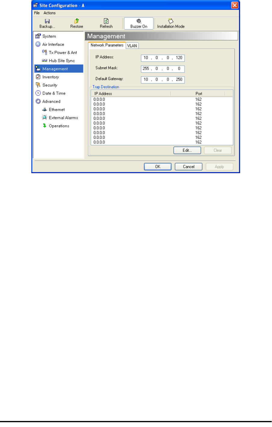
Figure 1-14: Site Configuration window with open Management panel

RADWIN 1000/2000/5000 User ManualVersion 2.5.30p3 2-1
Chapter 2
Site Preparation
Planning the Link Site
Overview
Link site planning consists of a set of surveys, which must be carried out
before any equipment is brought to the site. If for some reason, the out-
come of any of these surveys is negative, site re-location will need to be
considered.
A Site Survey consists of three stages:
1. Preliminary survey - The proposed link is analyzed in the office using a
topographic map.
2. Physical survey - The locations of the RADWIN 1000/2000/5000 indoor
and outdoor equipment are determined on-site.
3. Radio Frequency (RF) survey - It is recommended that the installation
area be scanned with a spectrum analyzer, to identify RF interference so
as to determine a clear channel for RADWIN 1000/2000/5000 installation
(on-site).
The Site Survey
Introduction
RADWIN 1000/2000/5000 wireless links must be planned before installa-
tion. The designated installation site must be appraised to determine that
the wireless system is able to operate efficiently and provide connectivity
without signal degradation.
RADWIN 1000/2000/5000 offers a wide operating frequency range. A free
frequency channel must be determined within the operating range, for opti-
mum performance.
Recommended Equipment
Stage 1: Preliminary Survey
• Topological map of the area

Stage 1: Preliminary Survey Chapter 2
RADWIN 1000/2000/5000 User ManualVersion 2.5.30p3 2-2
• Urban map of the area
• Compass
Stage 2: Physical Survey
• 100 meter tape measure
• Ohmmeter, to check ground connection
• Binoculars
• Map
• Digital camera
• Paper, pencil, and a clipboard
• GPS device (optional)
• Compass (optional)
Stage 3: RF Survey
• Spectrum Analyzer with Max Hold function and screen capture facil-
ity that can store multiple images, for documentation purposes
• RF accessories (connectors and cables)
• Communication devices (for example, cellular phones, or a set of
walkie-talkies)
Stage 1: Preliminary Survey
A preliminary survey is necessary before visiting potential installation sites.
As much detail as possible should be obtained about the two designated
ODU installation sites and the area between them.
To perform a preliminary survey:
1. Mark the two designated installation sites on a topographic map of the
area.
2. Measure the distance between the sites; check that it is within the speci-
fied range of the RADWIN 1000/2000/5000.
3. On the urban map, check for developed areas situated between the two
installation sites. Pay attention to these areas when performing the phys-
ical site survey; there may be tall buildings, RF towers, or transmitters,
which could cause interference to the link.
4. Check the area between the two sites for obstructions such as:
• High ground - hills or mountains
• Lakes or large bodies of water. Water has a reflection effect on RF
signals like a building. This type of reflection causes the received
amplitude to be reduced. As a rule of thumb, the presence of a large
body of water between the link sites may double the required
antenna height.
5. Determine and record the compass bearings between both ODUs, rela-
tive to north.
6. If there are obstructions between the two sites, calculate the Fresnel
Zone (see appendix D for details).

Stage 2: Physical Survey Chapter 2
RADWIN 1000/2000/5000 User ManualVersion 2.5.30p3 2-3
7. If the site chosen does not meet requirements, consider alternative sites.
8. Use the Link Budget Calculator (on the CD supplied with the RADWIN
1000/2000/5000 or using the RADWIN Manager) to determine the
expected performance.
Stage 2: Physical Survey
The physical site survey reviews the environment of the proposed RADWIN
1000/2000/5000 installation location, to ensure that the link sites are suit-
able for the wireless network. The results of the physical site survey should
be recorded.
To perform a physical survey:
1. From the compass readings taken in the preliminary survey, find the azi-
muth (horizontal position) that the ODU should face towards the second
ODU.
2. Using binoculars, locate any obstructions such as tall trees, high build-
ings, hills or mountains. Look for other RF towers between the two sites.
Mark the locations of the obstructions on the map.
3. Determine the location for the ODU (having regard for existing rooftop
installations and tower space). It should be above any obstructions, con-
sidering the Fresnel zone (see appendix D).
4. If you need to install the ODU on a tower, make sure that the tower is far
away from overhead electric power lines.
5. Determine a location for the indoor equipment; it should be as close as
possible to the ODU. At an existing site, there is probably an equipment
room with cable-routing channels.
6. Measure and record the path length of the cable from the ODU position
to the indoor equipment room.
7. Determine the ground and lightning connection points of the installation.
The RADWIN 1000/2000/5000 ODU and IDU must both be grounded.
8. Using the Ohmmeter, measure and record the resistance of the required
installation to the grounding point. The resistance must be less than 1O
ohm.
Note
It is advisable to go on a clear day, so you can more easily see any
obstructions between the two sites.
Note
The IDU - ODU cable length limit is 100m, in accordance with IEEE 10/
100BaseT standards.

Additional Outdoor Site Requirements Chapter 2
RADWIN 1000/2000/5000 User ManualVersion 2.5.30p3 2-4
9. Review the results of the physical site survey. Decide if the site is suitable
for the RADWIN 1000/2000/5000 wireless network installation.
• If the site is suitable, continue with stage 3, the RF survey
• If the site is not suitable, survey another site
Additional Outdoor Site Requirements
The ambient outdoor operating temperature should be -35 to 60C (-31 to
140F).
Additional Indoor Site Requirements
The following requirements guarantee proper operation of the system:
• For IDU-C units, allow at least 90 cm (36 “) of front clearance for
operating and maintenance accessibility. Allow at least 10 cm (4 “)
clearance at the rear of the unit for signal lines and interface cables
• The ambient operating temperature should be 0 to 50°C (32 to 122
°F) at a humidity of up to 90%, non condensing
Stage 3: RF Survey
The RF survey examines the wireless environment of the RADWIN 1000/
2000/5000 installation site, to determine whether there are available chan-
nels within the RADWIN 1000/2000/5000 operating frequency band. An RF
survey is performed using a spectrum analyzer.
It is advisable to familiarize yourself with the spectrum analyzer before
going out on site, specifically the Max Hold and Marker functions.
You should perform the RF survey at both proposed link sites.
The survey should be carried out during a busy time of day, to best judge
the worst-case radio interference. Allow 2-4 hours duration for a good RF
survey.
Note
It is possible to install the RADWIN 1000/2000/5000 link and use the
RADWIN Manager to find a clear channel. Each frequency channel can be
evaluated in turn. Achievement of a clear channel is indicated by the Quality
bar on the Channel Setting window (see figure 4-13) becoming green.

RADWIN 1000/2000/5000 User ManualVersion 2.5.30p3 3-1
Chapter 3
Hardware Installation
This chapter sets out the requirements and procedures for the hardware
installation and alignment of a RADWIN 1000/2000/5000 link in accordance
with the prior planning as set out in chapter 2. It is intended to guide quali-
fied field technicians.
Safety Practices
Preventing overexposure to RF energy
To protect against overexposure to RF energy, install the ODUs so as to pro-
vide and maintain minimal separation distances from all persons.
When the system is operational, avoid standing directly in front of the
antenna. Strong RF fields are present when the transmitter is on. The ODU
must not be deployed in a location where it is possible for people to stand
or walk inadvertently in front of the antenna.
Grounding
All RADWIN products should be grounded during operation. In addition:
• The ODU should be earthed by a wire with diameter of at least
12AWG.
The RADWIN 1000/2000/5000 ODU must be properly grounded to
protect against lightning. It is the user's responsibility to install the
equipment in accordance with Section 810 of the National Electric
Code, ANSI/NFPA No.70-1984 or Section 54 of the Canadian Electri-
cal Code. These codes describe correct installation procedures for
grounding the outdoor unit, mast, lead-in wire and discharge unit. It
Warning
Outdoor units and antennas should be installed ONLY by experienced
installation professionals who are familiar with local building and safety
codes and, wherever applicable, are licensed by the appropriate
government regulatory authorities. Failure to do so may expose the end
user or the service provider to legal and financial liabilities. RADWIN and its
resellers or distributors are not liable for injury, damage or violation of
regulations associated with the installation of outdoor units or antennas.

Protection against Lightning Chapter 3
RADWIN 1000/2000/5000 User ManualVersion 2.5.30p3 3-2
also lays down the size of grounding conductors and connection
requirements for grounding electrodes.
The RADWIN 1000/2000/5000 ODU must be grounded to a Protec-
tive Earth as described in appendix E and in accordance with the
Local Electrical Regulations.
• The earth lug on the IDU-C and IDU-E should be connected to the
protective earth at all times, by a wire with a diameter of 18 AWG
or wider. Rack-mounted equipment should be mounted only in
earthed racks and cabinets.
Further, you should -
• Always make the ground connection first and disconnect it last
• Never connect telecommunication cables to ungrounded equipment
• Ensure that all other cables are disconnected before disconnecting
the ground
More detailed guidelines are supplied in appendix E.
Protection against Lightning
The use of lightning protection is dependent on regulatory and end user
requirements. All of RADWIN outdoor units are designed with surge limiting
circuits to minimize the risk of damage due to lightning strikes. RADWIN
recommends the use of additional surge arrestor devices to protect the
equipment from nearby lightning strikes.
See appendix E for detailed installation instructions of lightning protection
devices.
General
• It is recommended that installation of the outdoor unit be contracted
to a professional installer.
• Before working on equipment connected to power lines or telecom-
munication lines, you should remove jewelry or any other metallic
object that may come into contact with energized parts.
• Use extreme care when installing antennas near power lines.
• Use extreme care when working at heights.
• When using an AC power source for RADWIN 1000/2000/5000
always use the AC power adapter supplied by RADWIN.
• Use the right tools. In addition to standard tools required for any
kind of ODU or antenna installation, RADWIN 1000/2000/5000
requires additional specific tools detailed on page 3-5 below.
Package Contents
The RADWIN 1000/2000/5000 packages include the following items:
ODU Package Contents
The ODU package contains:
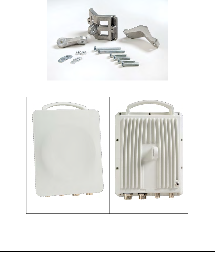
ODU Package Contents Chapter 3
RADWIN 1000/2000/5000 User ManualVersion 2.5.30p3 3-3
• One ODU - see figure 3-2 below for front and rear view
• An ODU mounting kit - see figure 3-1 below
• A CD containing -
• the RADWIN Manager
• Quick Start Guide
• User Manual
• Link Budget Calculator
• Label showing the MAC address and the alternative Community
string. The label is self-adhesive. You should keep this label safe
• Cable glands (to be used with the ODU-IDU cable)
Figure 3-1: ODU Mounting kit
Figure 3-2: Connectorized ODU - Front and rear views
ODU - Front View ODU - Rear View
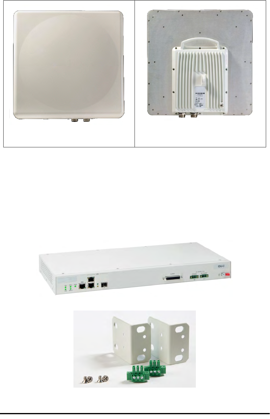
IDU Package Contents Chapter 3
RADWIN 1000/2000/5000 User ManualVersion 2.5.30p3 3-4
Figure 3-3: Integrated ODU - Front and rear views
IDU Package Contents
The IDU package contains:
• IDU-C - see figure 3-4 below.
• 19” rack mounting kit - see figure 3-5 below
• Two DC power plugs for power cables - see figure 3-5 below
Figure 3-4: IDU-C Package contents - the IDU-C
Figure 3-5: IDU-C Package contents - the mounting kit and DC power plugs
ODU - Front View ODU - Rear View

External Antenna Package Contents Chapter 3
RADWIN 1000/2000/5000 User ManualVersion 2.5.30p3 3-5
External Antenna Package Contents
• Antenna
• RF cable 1m (3’) long; two cables supplied with bipolar antennas,
single cable supplied with monopolar antennas
• Mounting kit
Additional Tools and Materials Required
The following is a list of the equipment and materials required to install
RADWIN 1000/2000/5000 hardware.
Tools and Materials
• Crimping tool for RJ-45 (if the ODU-IDU cable is without connectors)
• Spanner/wrench 13 mm (½”)
• Drill (for wall mounting only)
• Cable ties
• Sealing material
Cables and connectors
• ODU grounding cable 12AWG
• IDU grounding cable 18AWG
• ODU-IDU cable (outdoor class, CAT-5e, 4 twisted pairs, 24AWG)
Hardware Installation Sequence
The following steps are required to install the RADWIN 1000/2000/5000
system:
1. Mounting the ODUs, page page 3-6.
2. Mounting the external antennas (if used), page page 3-7.
3. Mounting the Lightning Protection devices (if used), page page 3-7.
4. Outdoor connections, page page 3-8.
5. Mounting the IDUs, page page 3-8.
6. Indoor connections, page page 3-12.
7. Aligning the ODUs/antennas, page page 3-13.
See figure 3-6 below, which illustrates a typical installation of RADWIN
1000/2000/5000 with an external antenna.
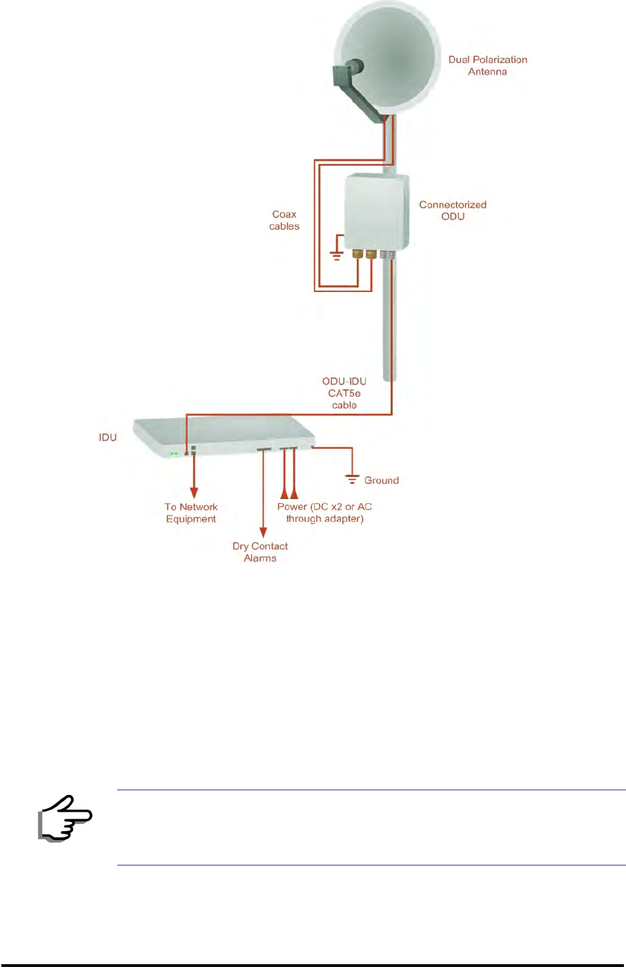
Outdoor installation Chapter 3
RADWIN 1000/2000/5000 User ManualVersion 2.5.30p3 3-6
Figure 3-6: Typical Installation Diagram (with external antenna)
The installation steps are detailed in the following sections.
Outdoor installation
Mounting the ODU
The ODU can be mounted on a pole or a wall. In both installations, the sup-
plied mounting kit is used to secure the ODU.
A RADWIN 1000/2000/5000 link operates in pairs of two ODUs with the
same configuration. Both ODUs must be installed, and the antennas aligned
for maximum throughput.
Note
A mast-sited ODU typically uses a pole attached to the mast.

Mounting external antennas Chapter 3
RADWIN 1000/2000/5000 User ManualVersion 2.5.30p3 3-7
To mount the ODU on a pole or a wall:
1. Ensure that the ODU is properly grounded.
2. Mount the ODU onto the pole or wall. Ensure that the unit is oriented so
that the cable connectors are at the bottom. (If they are on top,
water may penetrate into the unit causing damage.)
3. Refer to Appendix C, Pole and Wall Installation for detailed ODU
mounting kit contents and schematics.
Mounting external antennas
If you are using ODU with an integrated antenna, skip to Mounting the
Lightning Protection Devices below.
The supplied mounting kit is used to mount the antenna onto a pole. The
antennas must be aligned for maximum throughput.
To mount an external antenna:
1. To mount an external antenna ensure that the antenna is properly
grounded and then mount the antenna onto the pole. Refer to Appen-
dix C, Pole and Wall Installation for detailed antenna mounting
instructions.
2. Follow the mounting instructions supplied with the antenna.
Mounting the Lightning Protection Devices
The use of lightning protection is dependent on regulatory and end user
requirements. The RADWIN 1000/2000/5000 ODU is designed with surge
limiting circuits to minimize the risk of damage due to lightning strikes.
Warning
Prior to connecting cables to the ODU, the protective earth terminal (screw)
of the ODU must be connected to an external protective ground conductor
or to a grounded pole.
• Only a qualified person using the proper safety equipment should
climb the antenna mast
• Only qualified professional personnel should install or dismantle
ODUs and masts
Note
Do not tighten the ODU to its mounting brackets until the alignment
process of the antenna is complete.
Ensure that there are no direct obstructions in front of the ODU or
interference from man-made obstacles.
Warning
Do not stand in front of a live antenna.
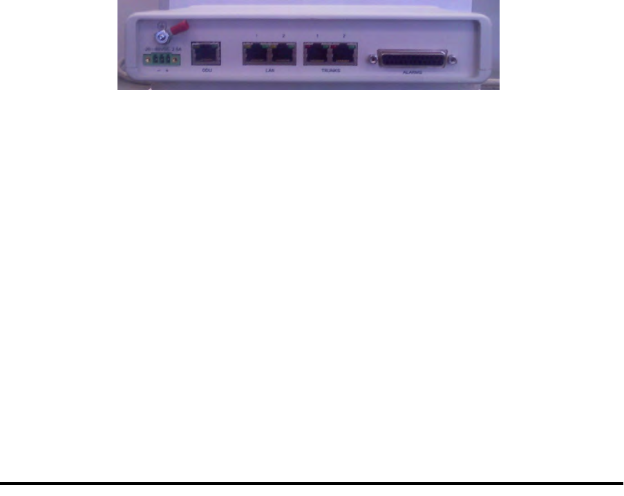
Outdoor Connections Chapter 3
RADWIN 1000/2000/5000 User ManualVersion 2.5.30p3 3-8
RADWIN recommends the use of additional surge arrestor devices to pro-
tect the equipment from nearby lightning strikes.
Refer to appendix E for detailed installation instructions of lightning protec-
tion devices.
Outdoor Connections
To complete the outdoor connections:
1. Connect the ground cable to the ODU chassis as marked on the ODU.
2. Connect the antenna cable(s) to the ODU.
3. Connect the lightning protection device to the ODU (see appendix E).
4. Attach the ODU-IDU cable to the ODU RJ-45 connector (see appendix B
for the connector pin-out)
5. Screw in the cable glands to ensure hermetic sealing of the ODU.
6. Secure the cables to the pole, mast or brackets using UV-rated cable ties.
Indoor Installation
IDU-E Installation
The IDU-E can be wall mounted, placed on a desktop or take up one half of
a 1U rack slot. The unit should be grounded, cabled to the ODU and con-
nected to power using the supplied AC/DC adapter.
Figure 3-7: New style IDU-E: Rear panel
Mounting the IDU-C
The RADWIN 1000/2000/5000 IDUs are all rack mounted, as shown in
figure 1-6. A front panel keyed schematic of a rack mounted IDU-C is
shown in figure 3-8 below.
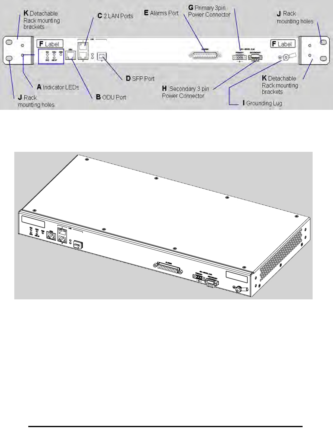
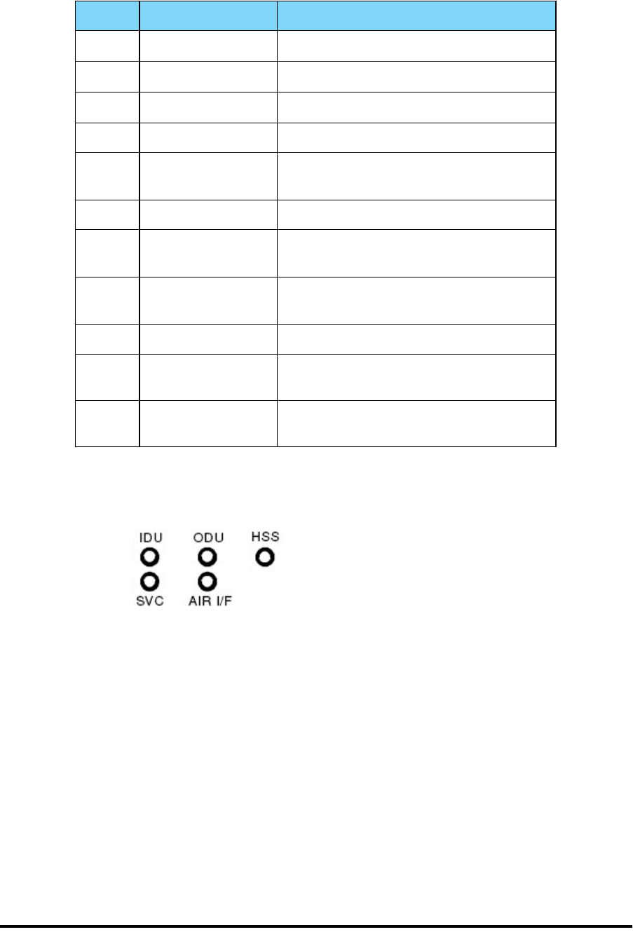
Mounting the IDU-C Chapter 3
RADWIN 1000/2000/5000 User ManualVersion 2.5.30p3 3-10
Further description of the keyed items in figure 3-8 is shown in table 3-1
below:
The Indicator LEDs (Item A in table 3-1 above) are shown in more detail in
figure 3-10 below:
Figure 3-10: IDU-C LEDs
Table 3-1: Components of an IDU-C front panel
Key Label Remarks
A Indicator LEDs See figure 3-10.
B ODU Port RJ-45 connector, see table B-1.
C 2 LAN Ports Ethernet, RJ-45 connector, see table B-2
D SFP Port The IDU-C is SFP ready.
E Alarm Ports Standard DB25 female connector, see
table B-3.
F Label indent Place for adhesive identification labels
G Primary 3 pin Power
Connector Standard 3 pins in line power connector,
see table B-4.
H Secondary 3 pin
Power Connector Standard 3 pins in line power connector,
see table B-4.
I Grounding Lug Use the lug supplied
J Rack mounting
holes
K Detachable Rack
mounting brackets

Connecting power to the IDU Chapter 3
RADWIN 1000/2000/5000 User ManualVersion 2.5.30p3 3-11
The purpose of the LEDs is shown in table 3-2 below:
To mount an IDU (using figure 3-8 above):
1. If the rack already holds other equipment, ensure that it is properly
grounded.
2. Attach the rack mounting brackets (K) to the IDU.
3. Bolt the IDU into an empty slot in the rack, ensuring that it sits securely.
4. Ground the IDU to the rack using grounding lug I. The IDU should be left
permanently grounded.
Connecting power to the IDU
The IDU-C has redundant power connection circuits (items G and H in
figure 3-8 above). An enlarged schematic of the power connectors is
shown in below:
Table 3-2: IDU-C Front Panel LEDs
Name Color Function
IDU Green
Green
Red
IDU operational
During power-up only
Failure
ODU Green
Red
ODU-to-IDU communication link is operating
ODU-to-IDU communication link is disrupted
AIR I/F Green
Orange
Red
Wireless link is synchronized
During installation mode only
Wireless link lost synchronization
SVC Off
HSS Off
Warning
Do not proceed with installation into a “live” rack unless it is properly
grounded.
Note
Instead of using the rack mounting brackets, the IDU may be rail mounted
using the four screw holes on each of its sides.

Connecting the ODU to the IDU Chapter 3
RADWIN 1000/2000/5000 User ManualVersion 2.5.30p3 3-12
Figure 3-11: DU-C ower connectors
The connectors are 3 pin in line female, with polarities (left to right) minus,
ground, plus. To avoid damage to the IDU, always use an AC/DC adapter
supplied by RADWIN.
Ensure that the IDUs at both sites are powered up.
Connecting the ODU to the IDU
The ODU-IDU cable conducts all the user traffic between the IDU and the
ODU, and also provides power to the ODU. The maximum length of the
ODU-IDU cable is 100m (328 ') in accordance with 10/100BaseT standards.
The ODU-IDU cable is supplied pre-assembled with RJ-45 connectors, at the
length specified when ordering, or as a cable drum with spare connectors. If
the ODU-IDU cable was not ordered, use an outdoor class, CAT-5e 24AWG
shielded cable. See appendix B for Wiring Specifications.
To connect the ODU to the IDU, route the cable from the ODU to the IDU,
secure the cable along its path and connect the cable to the ODU RJ-45
connector on the IDU (see item B in figure 3-8 above).
Installing a Link using PoE Devices
The PoE device is a very simple unit having a power input connector and
two Ethernet ports. It is AC powered, and has a power LED.
To prepare a link using PoE devices:
1. To connect the ODU to the PoE device, route the cable from the ODU to
the PoE device, secure the cable along its path and connect the cable to
the P-LAN-OUT RJ-45 connector on the PoE device.
2. Connect it to AC power.
3. Repeat steps 1 to 2 for the second link.
Connecting User Equipment
To connect user equipment to the IDU:
• Connect user switch/router or any other compatible device to the IDU
panel RJ-45 ports designated LAN (see item C in figure 3-8 above).

Connecting and Aligning ODUs / Antennas Chapter 3
RADWIN 1000/2000/5000 User ManualVersion 2.5.30p3 3-13
Refer to appendix B, Wiring Specifications, for connector pinouts.
To connect user equipment to the PoE device:
• Connect a user switch, router or any other compatible device to the PoE
device RJ-45 port designated LAN-IN. Refer to appendix B, Wiring
Specifications, for connector pinouts.
Connecting and Aligning ODUs / Antennas
You perform antenna alignment using the ODU's audible tone.
To speed up the installation time, alignment of a RADWIN 1000/2000/5000
system should be performed by two teams simultaneously, at site A and at
site B.
To align ODUs with integrated antennas or external bipolar antennas:
1. For external bipolar antennas: Using a coax cable with N-Type connec-
tors, connect the vertical polarization connector of the antenna to the
ANT 1 connector of the ODU.
2. For external bipolar antennas: Using a coax cable with N-Type connec-
tors, connect the horizontal polarization connector of the antenna to the
ANT 2 connector of the ODU.
3. Ensure that power is connected to the IDUs at both sites.
4. Ensure normal operation of the IDUs by the LED indications on the front
panel.
Provided that site A detects the signal from site B, the ODU starts beep-
ing 20 seconds after power up, and continues beeping until the ODUs are
aligned, and the installation is complete.
In the following steps, “antenna” refers both to an external antenna and
an integrated antenna.
5. Direct the antenna of site B in the direction of site A. This is simplified if
a previous site survey has been completed and azimuths are known.
6. Make a horizontal sweep of 180 degrees with the site A antenna so that
the strongest signal from site B can be detected.
Note
Do not connect two LAN ports to the same network, or flooding may occur.
Warning
When aligning the antennas, do not stand in front of a live antenna.
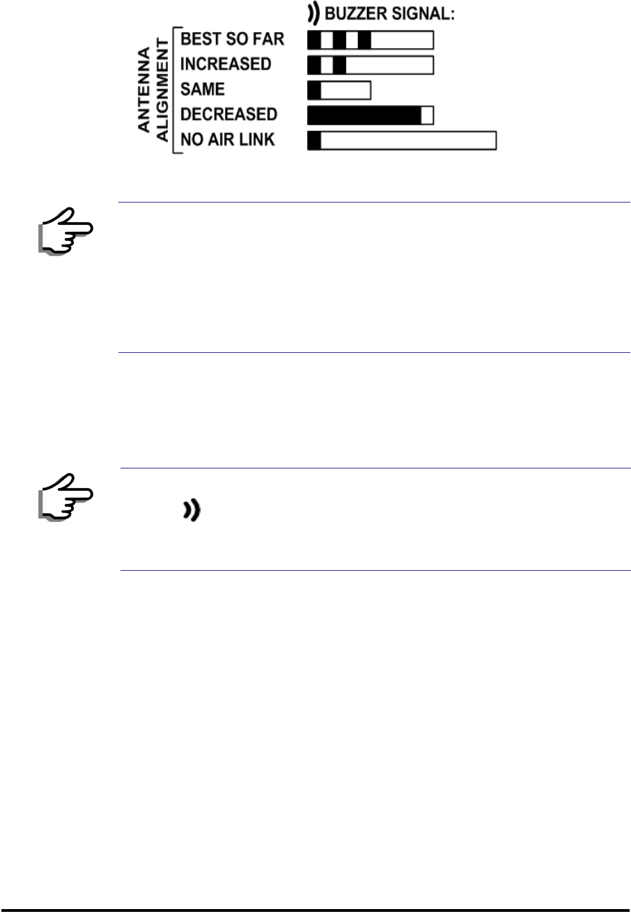
Connecting and Aligning ODUs / Antennas Chapter 3
RADWIN 1000/2000/5000 User ManualVersion 2.5.30p3 3-14
7. Slowly turn the site A antenna back towards the position of site B, listen-
ing to the tone until the best signal is reached. See the following figure
for audible signal variations.
Figure 3-12: Beep Sequence for antenna alignment
8. Secure the site A antenna to the pole/wall.
9. Repeat steps 4 to 8 for site B.
To align two external monopolar antennas:
1. Using a coax cable with N-Type connectors, connect one antenna to the
ANT 1 connector of the ODU.
2. Follow the steps 3 to 7 above to align the antenna connected to the ODU
connector ANT 1 on both sides of the link.
3. On both sides of the link, disconnect the antenna connected to the ODU
connector ANT 1. Connect the other antenna to connector ANT 1 and fol-
low the steps 3 to 7 above to align the second antenna.
4. Secure the antennas to the pole/wall.
5. Restore one of the antennas to ANT 2 on both sides of the link.
Note
• Three beeps and a pause is 'best signal so far'
• Two beeps and a pause is 'signal quality increased'
• One beep and pause is 'no change in signal'
• Long beep and short pause is 'signal quality decreased'
• One beep and a long pause is 'no air link'
• Any other signal does not relate to antenna alignment
Note
The ODU buzzer only works on the radio connected to the ANT 1 connector
marked . You will therefore need to use ANT 1 to align both antennas
in turn. Upon completion of the alignment procedure, you may connect the
two antennas to ANT 1 and ANT 2 connectors.

RADWIN 1000/2000/5000 User ManualVersion 2.5.30p3 4-1
Chapter 4
Link Installation: The
RADWIN Manager
This chapter explains how to use the RADWIN Manager to install a radio
link.
Installing theRADWIN Manager Application
Minimum System Requirements
The RADWIN Manager application is distributed on a CD. Operating system
specific PC resources required by the application are set out in table 4-1
below:
Requirements common to all systems are:
• Hard disk: 1 GB free space
• Network: 10/100BaseT NIC
• Graphics: 1024x768 screen resolution with 16 bit color
• Microsoft Explorer version 5.01 or later
Installing the Software
To install the RADWIN Manager application:
1. Insert the CD into the CD/DVD drive of your computer.
The CD opening screen appears:
Table 4-1: PC Requirements for the RADWIN Manager Application
Windows 2000 Windows XP Pro Windows Vista
Memory 128 MB 512 MB 1 GB
Processor P III P IV P IV Dual Core
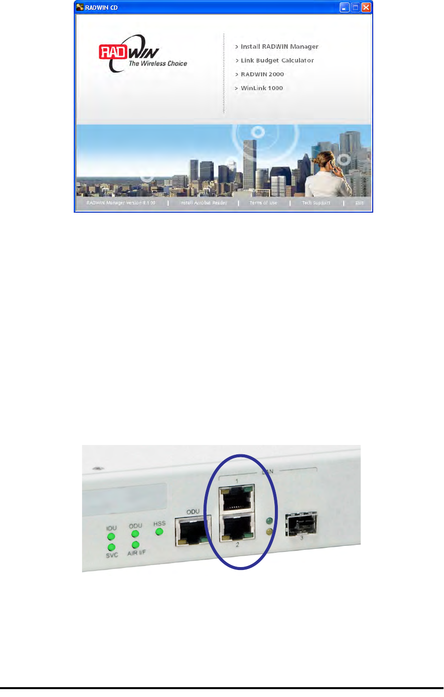
Starting the RADWIN Manager Chapter 4
RADWIN 1000/2000/5000 User ManualVersion 2.5.30p3 4-2
2. Choose Install RADWIN Manager and follow the on-screen instructions
of the installation wizard to complete the setup of the RADWIN Manager
application.
If the installation program fails to start, browse to your CD/DVD drive,
chose the setup.exe program and run it.
Any PC running the RADWIN Manager application can be used to configure
a RADWIN 1000/2000/5000 link.
Starting the RADWIN Manager
To start the RADWIN Manager:
1. Connect the managing computer to one of the two LAN ports as shown
in figure 4-1 below:
Figure 4-1: LAN ports on the front panel of the IDU-C
If you are not using a direct connection as above, ensure that you have
IDU to managing computer connectivity (e.g. through a LAN).
2. Check that you have connectivity to the ODU. You can do this by opening
up a command line session (Start|Run and then type, cmd). At the
command prompt, type
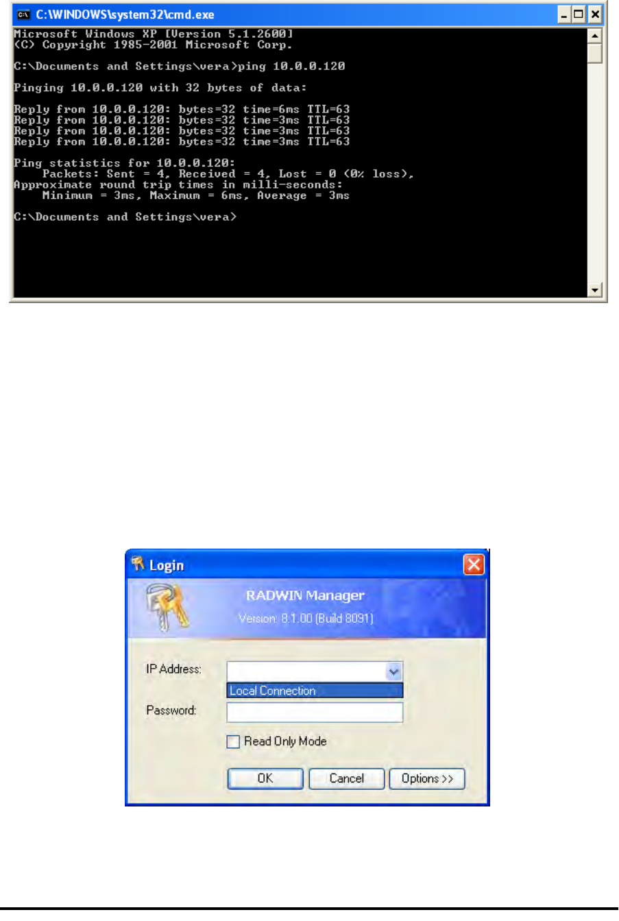
Starting the RADWIN Manager Chapter 4
RADWIN 1000/2000/5000 User ManualVersion 2.5.30p3 4-3
ping 10.0.0.120
You should see something like this:
Figure 4-2: Pinging an uninstalled and unconfigured link
Any other response from ping means that the ODU is not responding.
Check your Ethernet connection and that both the the IDU and ODU are
switched on and then try again. If you do not succeed, seek assistance
from RADWIN Customer Support.
3. Dismiss the command line session.
4. Double-click the RADWIN Manager icon on the desktop, or click
Start|Programs|RADWIN Manager|RADWIN Manager.
The Login dialog box appears.
Figure 4-3: Login Screen
5. Type an IP address for the ODU (if you connect through a network), or
click Local Connection (if you are connected directly to the IDU port).

Starting the RADWIN Manager Chapter 4
RADWIN 1000/2000/5000 User ManualVersion 2.5.30p3 4-4
6. Enter the password
7. If you are a user with Read-Write permission, click Options to enter the
Community options.
Warning
1. If you log in on Local Connection, but your physical connection is
not local (i.e. anything other than a direct connection between
the managing computer and the IDU), then any configuration
you carry out may affect other links in the network.
2. If you log in via an over-the-air IP address, you will receive a
warning. If you reset the site to which you are connected to
factory settings, you can lock yourself out of the Link.
3. Network login (IP address to the ODU) is recommended.
Note
The default IP address for the ODU is 10.0.0.120. The subnet mask is
255.0.0.0.
The actual IP address is defined during link configuration (see Site
Management: IP Address and VLAN on page 6-4).
Note
The default password is admin (see Changing the Log On Password on
page 4-7).
Note
RADWIN 1000/2000/5000 is protected with Community passwords. A user
may be defined with read-only permission or with read-write permission
(see page 6-14 for more details).
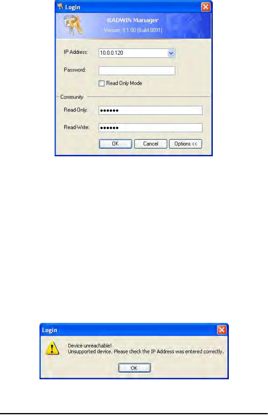
Login Errors Chapter 4
RADWIN 1000/2000/5000 User ManualVersion 2.5.30p3 4-5
Figure 4-4: Login Screen with Community options visible
• If you are using the system for the first time, leave the default Com-
munity passwords, netman for read-write, and public for read-
only.
• If Community values were previously defined, enter them under
Community in the Read-Only or Read-Write boxes.
• If you are a user with read-only permission, click the Read Only
Mode check box.
The RADWIN Manager main window is displayed (see figure 4-7).
Login Errors
Unsupported Device
Attempting to connect to an unsupported device will result in the following
error message:
Figure 4-5: Unsupported device message

Incorrect IP Address Chapter 4
RADWIN 1000/2000/5000 User ManualVersion 2.5.30p3 4-6
Incorrect IP Address
If the IP address chosen is invalid or the link is unreachable, the following
error message will be displayed:
Figure 4-6: Unreachable device message
In both of the above situations, you will see a warning graphic along-
side the IP Address field.
Incorrect Password
If you type an incorrect password in the Login screen, you will see a warn-
ing graphic alongside the password field.
Continuing without an IP Address
The RADWIN Manager provides limited “offline” functionality when there is
no accessible IDU/ODU. It is primarily for setting managing computer
related parameters and running the Link Budget Calculator. The offline func-
tionality is shown in table 4-2 below. The table does not show menu items
grayed out.

Changing the Log On Password Chapter 4
RADWIN 1000/2000/5000 User ManualVersion 2.5.30p3 4-7
Changing the Log On Password
To change the log on password:
1. From the Tools menu, select Change Password.
The Change Password dialog box appears.
2. Enter the current password, and the new password.
3. Click OK to confirm.
Installing the Link: First steps
At this point the main window of the RADWIN Manager should be displayed:
Table 4-2: RADWIN Manager: Offline Functionality
Menu level Function Reference
Top +1 +2
File
Log Off Return to Log On dialog.
Same as Log Off button
Exit Exit the RADWIN Manager.
Same as Exit button
Tools
Change
Password Change the Log On pass-
word dialog page 4-7
Events Log page 7-10
Clear
Events Clear local events log
Save to
File Save events log data to a file
Help
RADWIN
Manager
Help
View online help version of
the User Manual
Link Budget
Calculator Calculator opened in default
browser Appendix D
Get
Diagnostics
Information
Obtain system information page 7-1
About
RADWIN
Manager
RADWIN Manager build
information
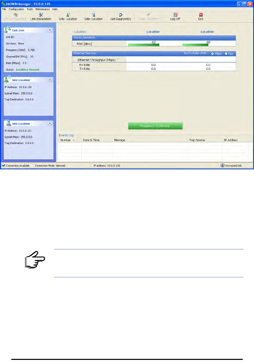
Installing the Link: First steps Chapter 4
RADWIN 1000/2000/5000 User ManualVersion 2.5.30p3 4-8
Figure 4-7: Opening RADWIN Manager window prior to installation
A detailed field by field description of the contents of the RADWIN Manager
main window may be found in chapter 5.
The procedure required to make the link functional has three phases:
1. Link Installation - which we will detail below.
Installation actually gets the link operational by setting the link parame-
ters. It uses a fixed channel at the lowest possible modulation, BPSK at
6.5Mbps and will work under the harsh interference condition.
2. Link Configuration - described in chapter 5.
Configuration provides much the same functionality as Installation, but
for a running link. A fallback to Installation mode is provided for situa-
tions which cannot be handled without resetting the link, such as
antenna realignment and IDU or ODU replacement.
The Link Installation and Configuration phases are both carried out with
Wizards, which “walk you through” the processes. The Wizards are visu-
ally quite similar and will be described in detail below.
Note
During the installation procedure, the definition of all parameters is
automatically applied to both sides of the link.

Default Settings Chapter 4
RADWIN 1000/2000/5000 User ManualVersion 2.5.30p3 4-9
3. Site Configuration - described in chapter 6.
Site specific configuration for each side of the link is available at any time
- under a running link or under the restricted Installation mode.
Site Configuration consists of a set of panels, which may be invoked indi-
vidually in any order, as needed.
Default Settings
The default settings of the RADWIN 1000/2000/5000 configuration parame-
ters are listed in table 4-3 below:
Front Panel LEDs on the IDU-C
The front panel LEDs on the IDU provide basic information about link sta-
tus.
Note
An installed and configured link can be returned to installation mode for re-
installation and configuration from last settings or from factory settings.
• Reversion to installation mode requires a complete break in the link
service
• Configuration mode may vary the service throughput and quality, but
without a service break
Table 4-3: Default Settings
Parameter Default Value
ODU IP Address 10.0.0.120
Subnet Mask 255.0.0.0
Trap destination 0.0.0.0
Manager Login password admin
Link ID Link
Site 1 Site
Site 2 Site
Link Password wireless-bridge
Rate Adaptive
Ethernet Configuration Auto Detect
Radio Link Failure Actions No action
Bridge or Hub mode Hub Mode, Aging time = 300 sec
Community values Read-write – netman
Read-only – public

Installation Menu and Toolbar Functionality Chapter 4
RADWIN 1000/2000/5000 User ManualVersion 2.5.30p3 4-10
Figure 4-8: IDU-C Front Panel LEDs
The following table describes the indicators:
Installation Menu and Toolbar Functionality
The RADWIN Manager menu functionality is displayed in table 4-5. The
Toolbar buttons are detailed in table 4-6.
Table 4-4: Front Panel LEDs
Name Color Function
IDU
With Ethernet only
Green
Green
Red
During power-up only
IDU operational
Failure
ODU Green
Red
ODU-to-IDU communication link is operating
ODU-to-IDU communication link is disrupted
AIR I/F Green
Orange
Red
Wireless link is synchronized
During installation mode only
Wireless link lost synchronization
SVC Off
HSS Off

Installation Menu and Toolbar Functionality Chapter 4
RADWIN 1000/2000/5000 User ManualVersion 2.5.30p3 4-11
Table 4-5: RADWIN Manager main menu functionality
Menu level Function Reference
Top +1 +2
File
Log Off Return to Log On dialog.
Same as Log Off button
Exit Exit the RADWIN Manager.
Same as Exit button
Configuration
Link
Configuration
Run the Configuration Wiz-
ard. Not available in
installation mode
1 Configure
<Site 1 name>
Provides limited configura-
tion for site. Has a path to
return to installation
mode
2 Configure
<Site 2 name>
Provides limited configura-
tion for site. Has a path to
return to installation
mode
Link Installation Runs the Installation Wiz-
ard. Not available in
configuration mode
Tools
Performance
Monitoring
Report
Active Alarms
1 <Site 1 name> Shows active alarms for
<Site 1 name>
2 <Site 2 name> Shows active alarms for
<Site 1 name>
Change
Password Change the Log On pass-
word dialog page 4-7
Events Log
page 7-10
Clear Events Clear local events log
Save to File Save events log file
Preferences Local preferences dialog

Installation Menu and Toolbar Functionality Chapter 4
RADWIN 1000/2000/5000 User ManualVersion 2.5.30p3 4-12
Maintenance
Clear counters Disabled
Loopbacks Disabled
Reset 1 <Site 1 name> Reset <Site 1 name> ODU
2 <Site 2 name> Reset <Site 2 name> ODU
Help
RADWIN
Manager Help View online version of the
User Manual
Link Budget
Calculator Calculator opened in
default browser Appendix D
Get Diagnostics
Information Obtain system information page 7-1
About RADWIN
Manager Manager build and system
information
Table 4-6: RADWIN Manager Toolbar
Item Description
Link Configuration Changes configuration parameters of an operating wireless link;
assigns text files for storing alarms, statistics and configuration
data. This button is disabled until a link installation has
been completed
Link Installation Performs preliminary configuration of the system. This button is
disabled after the link is installed
Site: <Site 1 name> Opens the Site configuration dialog for Site A. Same as
Configuration | 1 Configure <Site 1 name>
Site: <Site 2 name> Opens the Site configuration dialog for Site B. Same as
Configuration | 2 Configure <Site 2 name>
Get Diagnostics Obtain system information
Clear Counters Disabled
Log off Closes the current session and logs off RADWIN Manager
Exit Exits RADWIN Manager
Table 4-5: RADWIN Manager main menu functionality (Continued)
Menu level Function Reference
Top +1 +2
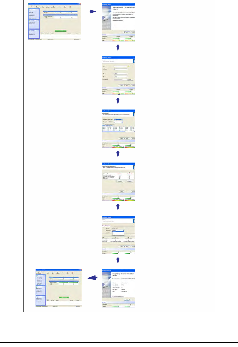
Installing the Link: Overview Chapter 4
RADWIN 1000/2000/5000 User ManualVersion 2.5.30p3 4-13
Installing the Link: Overview
The Installation wizard has seven steps as shown in table 4-7 below.
Table 4-7: Link Installation Wizard
1Wizard welcome
2System parameters
• Link ID
• Site details
3Channel settings - ACS
Configuration
4Tx power and antenna
settings
5Services - Adaptive or
fixed
6Wizard summary and
completion
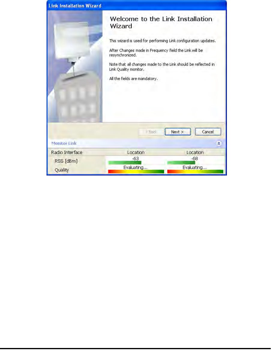
Installing the Link: Step 1, Start the Wizard Chapter 4
RADWIN 1000/2000/5000 User ManualVersion 2.5.30p3 4-14
Installing the Link: Step 1, Start the Wizard
In the tool bar of the RADWIN Manager main window, click the Link
Installation button. The Link Installation button is only accessible if anten-
nas are properly aligned. If this box is “grayed out”, you should align the
antennas as set out in Connecting and Aligning ODUs / Antennas on
page 3-13.
The Installation Wizard opens:
Figure 4-9: Link Installation Wizard
The bottom data area reproduces the corresponding data from the main
window - which the above panel obscures. See page 5-7 for a field by field
description of this data area.
Click Next to proceed with the installation procedure.
Installing the Link: Step 2, System Parameters
The system dialog box opens:
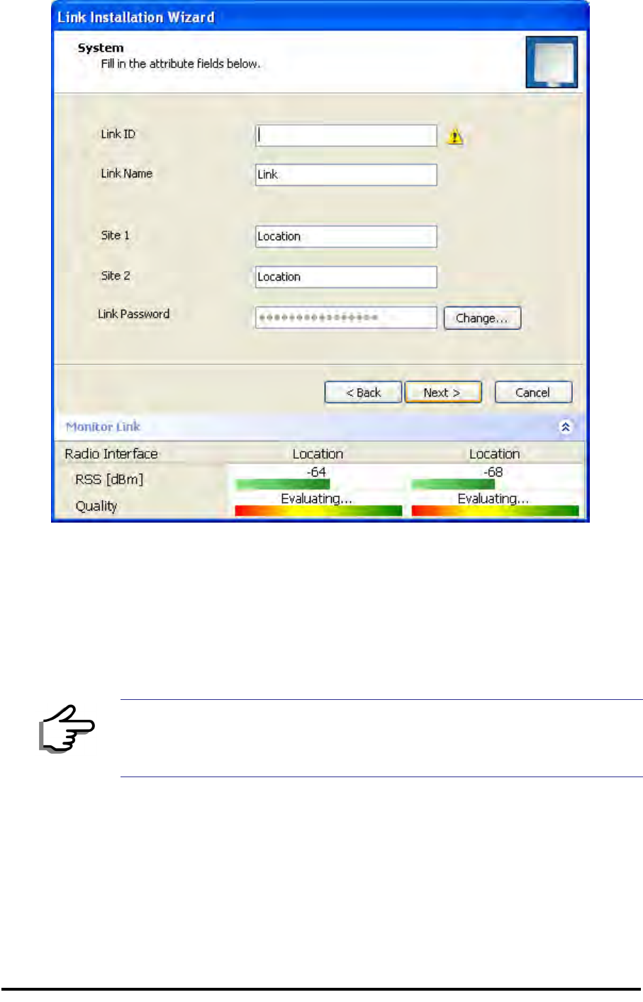
Installing the Link: Step 2, System Parameters Chapter 4
RADWIN 1000/2000/5000 User ManualVersion 2.5.30p3 4-15
Figure 4-10: : Installation Wizard, System dialog box
To complete Installation Step 2:
1. Enter a Link ID. (Link ID - must be unique for each link in the area). The
Link ID must include at least eight alphanumeric characters. Up to 24
characters are allowed.You should use a Link ID composed of both
alphabetic and numeric characters.
2. Enter a Link Name for the link identification. The default name is “Link”.
You should change it.
3. Enter names for Site 1 and Site 2. The default names are both “Loca-
tion”. You should change them. Throughout this manual, we use A for
Site 1 and B for Site 2.
Note
Both sides of a link must have the same Link ID.
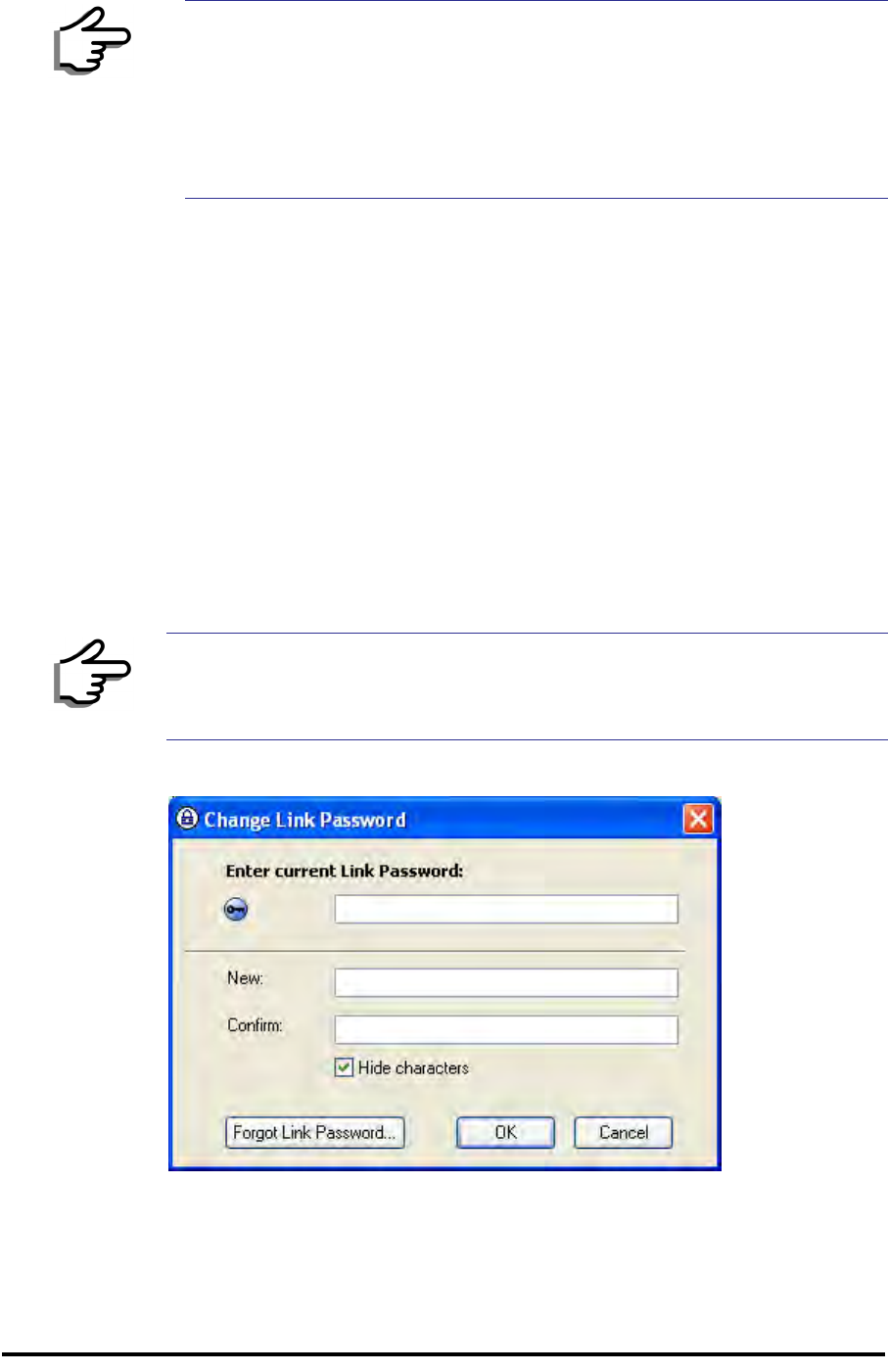
Changing the Link Password Chapter 4
RADWIN 1000/2000/5000 User ManualVersion 2.5.30p3 4-16
4. Optionally enter a new Link Password.
5. Click Next.
The default link with a rate of 6.5 Mbps is evaluated.
The Channel Setting dialog box appears. Proceed to Installing the
Link: Step 3, Channel Settings, below.
Changing the Link Password
The default password is wireless-bridge. Optionally, you can change the
link password as explained here.
To change the link password:
1. Click the Change button in the System dialog box.
The Change Link Password dialog box opens.
Figure 4-11: Change Link Password dialog box
2. Enter the current link password (The default link password for a new
ODU is wireless-bridge).
Note
If the Link Password is incorrect a link is established but configuration
cannot be performed and no services are available. A new link password
may be obtained from RADWIN Customer Support or use the alternative
password supplied with the product. (see for more details).
The link password is peculiar to the link itself and should not be confused
with the RADWIN Managerlog on password.
Note
Use the Hide characters check box for maximum security

Installing the Link: Step 3, Channel Settings Chapter 4
RADWIN 1000/2000/5000 User ManualVersion 2.5.30p3 4-17
If you have forgotten the Link Password, click the Forgotten Link Pass-
word button. The following window is displayed:
Figure 4-12: Lost or forgotten Link Password recovery
Follow the instructions to use the Alternative Link Password, and click
OK to finish. You are returned to the window in figure 4-11 above.
Continue with the next step.
3. Enter a new password.
4. Retype the new password in the Confirm field.
5. Click OK.
6. Click Yes when asked if you want to change the link password.
7. Click OK at the Password changed success message.
Installing the Link: Step 3, Channel Settings
RADWIN 1000/2000/5000 systems have a feature called Automatic Channel
Selection (ACS). In the event of sync loss, ACS chooses the first available
channel in a list of monitored channels nominated in the Channel settings
window of figure 4-13 below. A channel switch takes place sufficiently fast
as to ensure no loss of service.
Note
• Restoring Factory Defaults returns the Link Password to wireless-
bridge.
• If the link is inactive, then the link password may also be changed
from the Site Configuration dialogs. See page 6-14.
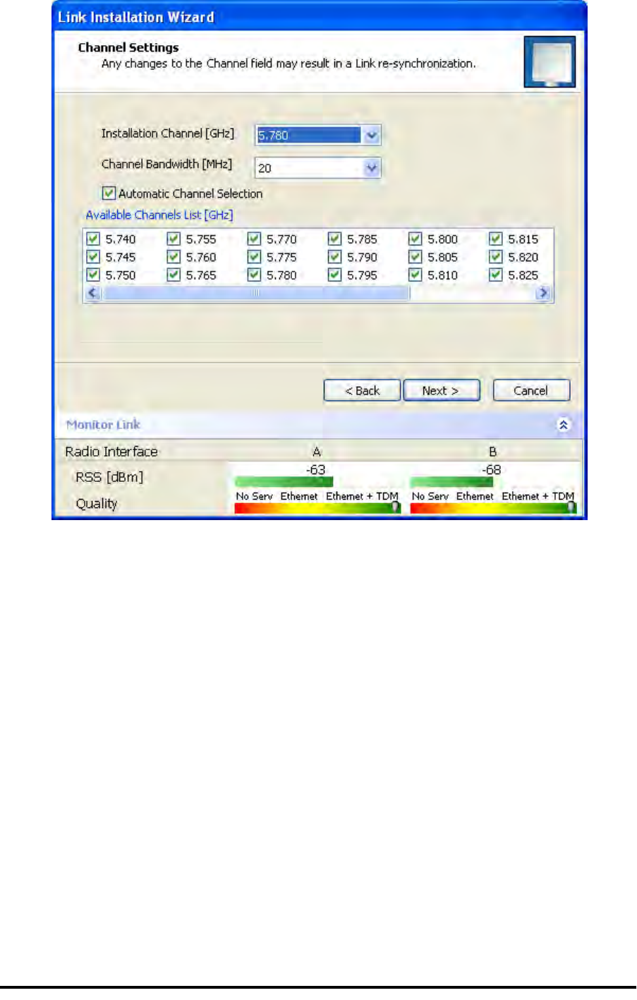
Installing the Link: Step 3, Channel Settings Chapter 4
RADWIN 1000/2000/5000 User ManualVersion 2.5.30p3 4-18
Figure 4-13: Channel Settings - Automatic Channel Selection
The default frequency for the product is shown.
To select channels to be used by the link:
1. Select the main frequency from the Installation Channel box.
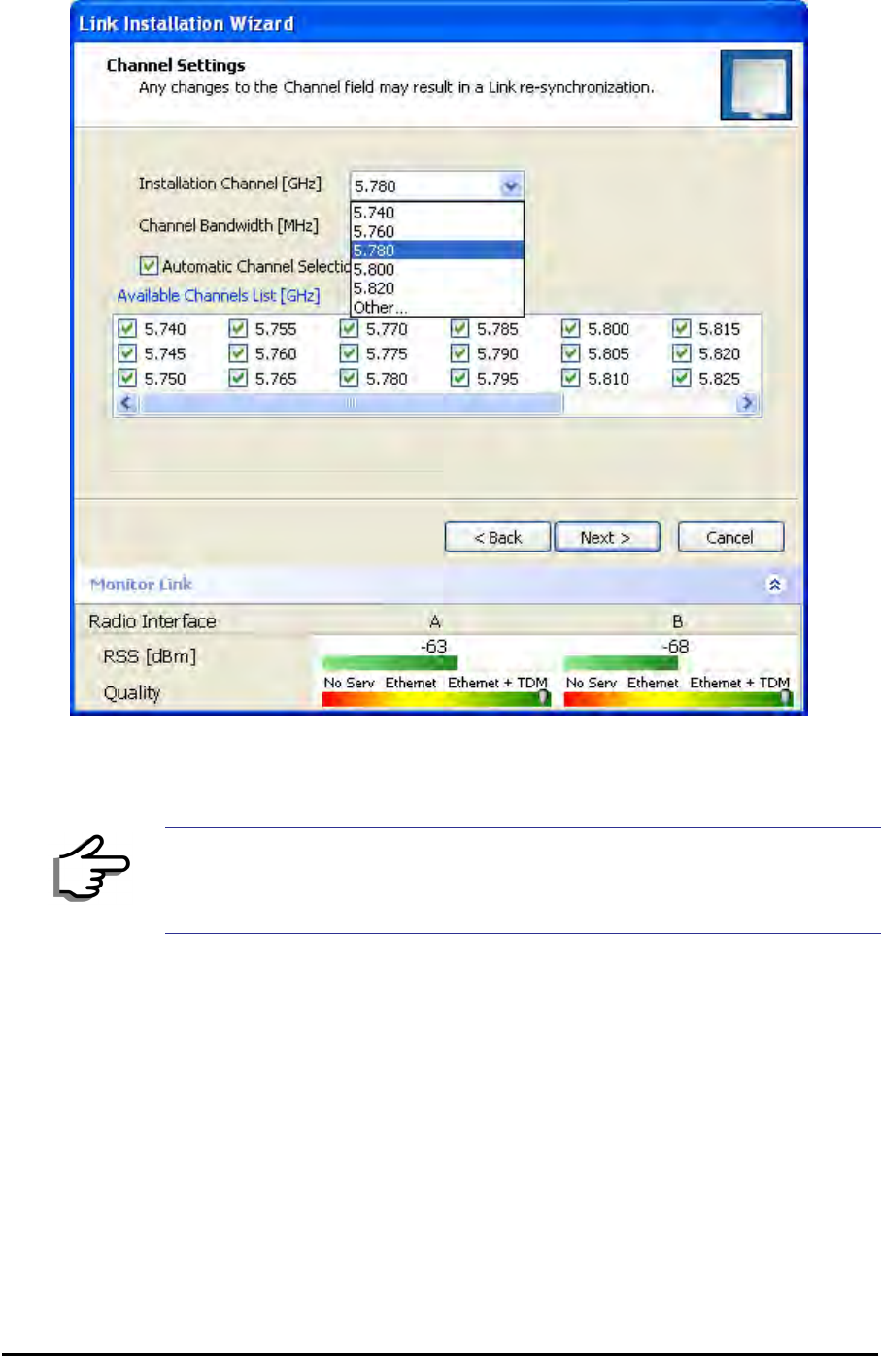
Installing the Link: Step 4, Tx Power and Antenna Settings Chapter 4
RADWIN 1000/2000/5000 User ManualVersion 2.5.30p3 4-19
Figure 4-14: Channel Settings - Showing available installation rates
2. Click the check box if Automatic Channel Selection is required.
3. The Available Channels List contains all of the allowable channels for the
link. Check the channels that can be automatically selected.
Selecting a new channel causes the system quality to change. The Qual-
ity bar provides an indication of the link quality from poor (red) to good
(green) as shown in the bottom of figure 4-13 above.
4. Click Next.
Installing the Link: Step 4, Tx Power and Antenna Settings
The Tx Power and Antenna Parameters dialog appears.
Note
For version 2.1, channel bandwidth is set to 20 MHz and cannot be
changed.
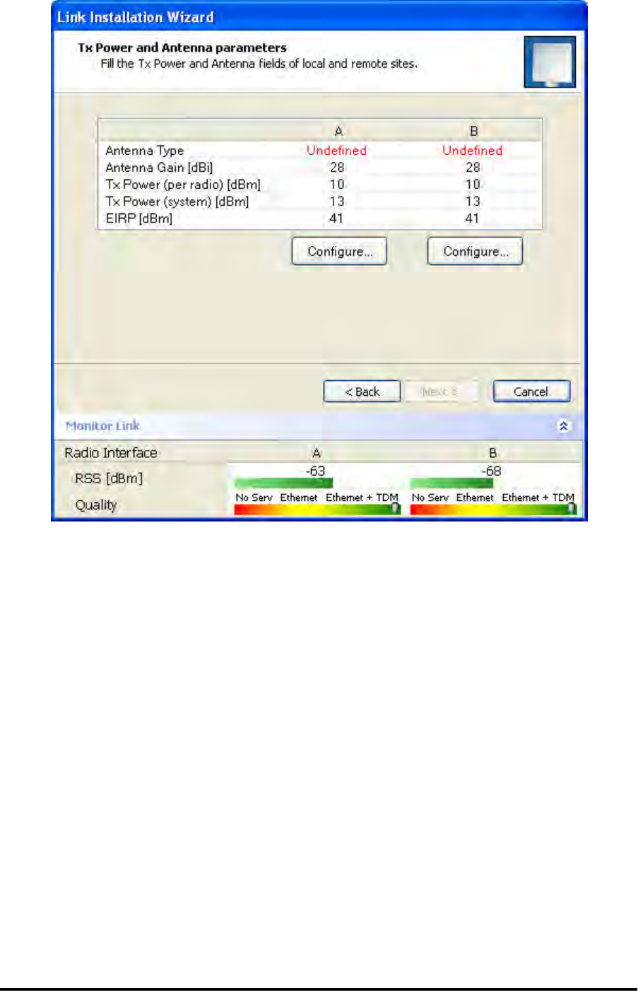
General Chapter 4
RADWIN 1000/2000/5000 User ManualVersion 2.5.30p3 4-20
.
Figure 4-15: Transmission Power and Antenna Parameters
The choice of Tx power, antenna gain and cable loss determines the EIRP
and is affected by such considerations as radio limitations and regulatory
restrictions.
Before proceeding to antenna installation details, the following background
information should be considered:
General
Each RADWIN 1000/2000/5000 ODU is made of two radio transceivers
(radios). The radios make use of algorithms that utilize both polarization
and space diversity resulting in enhanced capacity, range and link availabil-
ity. The number of antennas (i.e. radios) used is determined by user config-
uration and by automatic system decisions, explained below.
Dual Antennas at Both Sites
Using dual antennas at both sites (single bipolar antenna or two monopolar
antennas) enables the use of MIMO technology. With MIMO the system
doubles the link capacity. At the same time, it keeps the same rate and
modulation per radio as was used with single antenna, thus increasing
capacity, range and availability.

Single Antennas at Both Sites Chapter 4
RADWIN 1000/2000/5000 User ManualVersion 2.5.30p3 4-21
For example with a dual antenna RADWIN 1000/2000/5000 can transmit at
modulation of 64QAM and FEC of 0.83 and get an air rate of 130 Mbps,
compared to 65 Mbps with single antenna.
To work in this mode, each antenna port must be connected to an antenna,
the RSS level in both receivers should be balanced and a minimal separation
between the antennas must be maintained. (For example, by using dual
polarization antennas a cross polarization separation is attained).
Upon selecting Antenna Type as Dual, RADWIN 1000/2000/5000 automati-
cally doubles the air rates.
RADWIN Manager indicates a case of unbalanced RSS between the two
antennas.
Single Antennas at Both Sites
By selecting a single antenna at both sites the ODUs operate with a single
radio that is connected to the ANT 1 connector. The second radio is auto-
matically shut down.
Single and Dual Antennas
In this mode one of the sites uses the ODU with a single antenna while the
other site uses the ODU with a dual antenna.
The advantages in this mode in comparison to using a single antenna in
both sites are doubled total Tx power and additional polarization and/or
space diversity.
RADWIN 1000/2000/5000 automatically switches to this mode if one of the
ODUs is connected to a dual antenna or if the RSS at one of the ODU receiv-
ers is below minimal level.
The air rates used in this mode are same as when using single antennas in
both sites.

Considerations for Changing Antenna Parameters Chapter 4
RADWIN 1000/2000/5000 User ManualVersion 2.5.30p3 4-22
The rates used by RADWIN 1000/2000/5000 are shown in Table 4-5 below:
Considerations for Changing Antenna Parameters
Let:
maxAllowedTx Power denote the maximum Tx Power practically avail-
able from an ODU. It appears as Tx Power per Radio in
figure 4-16 below.
maxRegEIRP denote the maximum EIRP available by regulation. It will be
determined by three factors:
• per band/regulation
• per channel bandwidth
• antenna gain
It appears in figure 4-16 as Max EIRP.
maxRegTxPower denote the maximum regulatory Tx Power for the
equipment, also having regard the above three points
Table 4-8: RADWIN 1000/2000/5000 Transmission rates
Radio Modulation FEC Air-Rate
[Mbps]
Single BPSK 1/2 6.5
Single QPSK 1/2 13
Single QPSK 3/4 19.5
Single 16QAM 1/2 26
Single 16QAM 3/4 39
Single 64QAM 2/3 52
Single 64QAM 3/4 58.5
Single 64QAM 5/6 65
Dual BPSK 1/2 13
Dual QPSK 1/2 26
Dual QPSK 3/4 39
Dual 16QAM 1/2 52
Dual 16QAM 3/4 78
Dual 64QAM 2/3 104
Dual 64QAM 3/4 117
Dual 64QAM 5/6 130
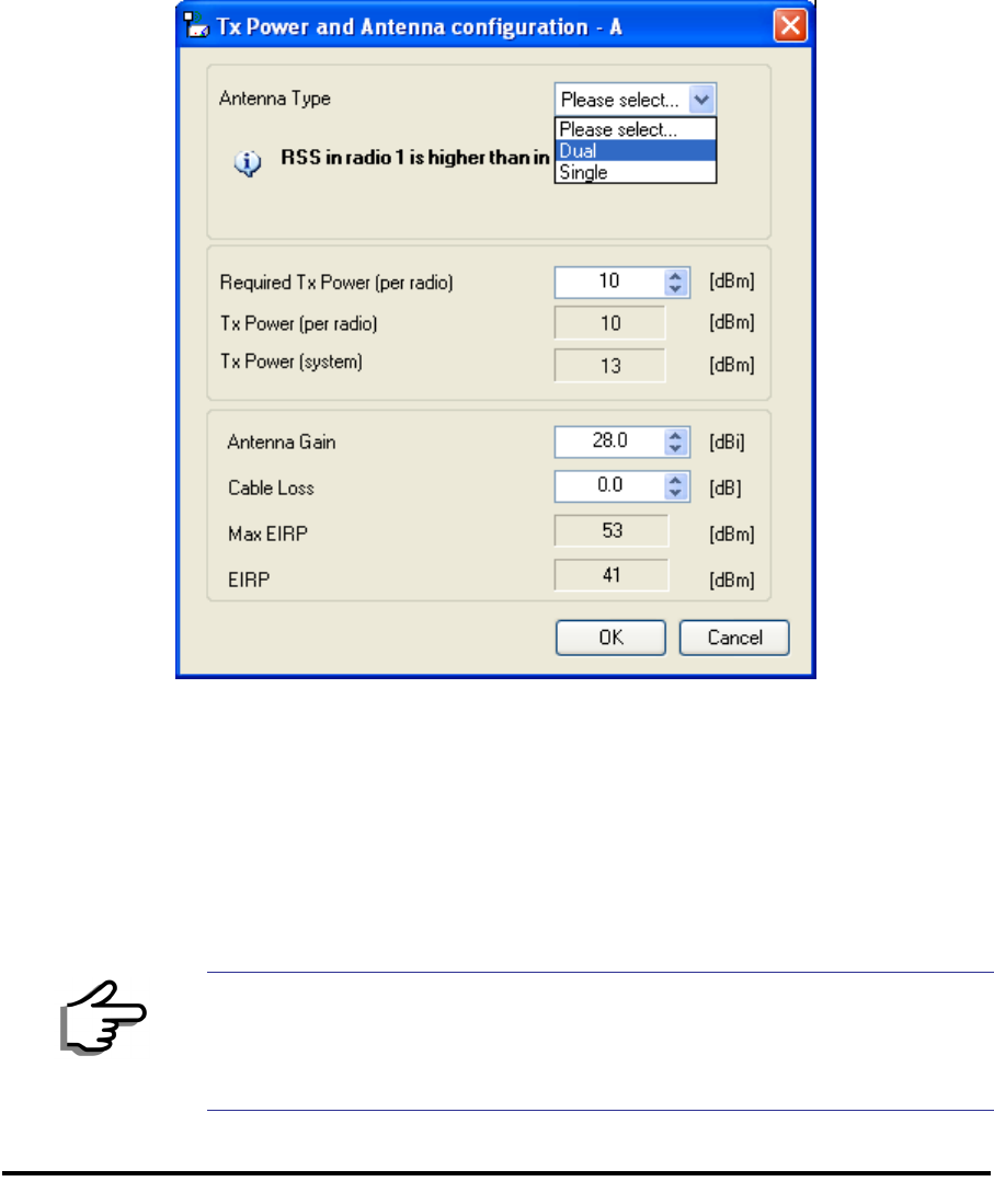
Considerations for Changing Antenna Parameters Chapter 4
RADWIN 1000/2000/5000 User ManualVersion 2.5.30p3 4-23
maxODUTxPower denote the maximum Tx Power of the ODU, itself
depending on the air rate used.
Then, the following relationship must be satisfied: ... (*)
These parameters are controlled as follows:
To set Tx power and configure antennas:
1. Click the Configure buttons in turn to configure the antennas on both
sides of the link. Each one offers a dialog like this:
Figure 4-16: Antenna configuration dialog with opened type selection
2. Choose the antenna type and required transmission (Tx) power for the
first site and click OK. Repeat the process for the second site.
The Tx power (per radio) indicates the power of each radio inside the
ODU and is used for Link Budget Calculations. The Tx power (System)
shows the total transmission power of the ODU and is used to calculate
the EIRP according to regulations.
Note
To see the relationship between Tx Power (radio) and TX Power (system),
note that so that if you double the power in
milliWatts (for two radios) then dBm will increase by .
maxAllowedTxPower min maxRegEIRP
AntennaGain CableLoss maxRegTxPower+– ()
dBm 10 milliWatt
10
log=
10 2 3
10
log
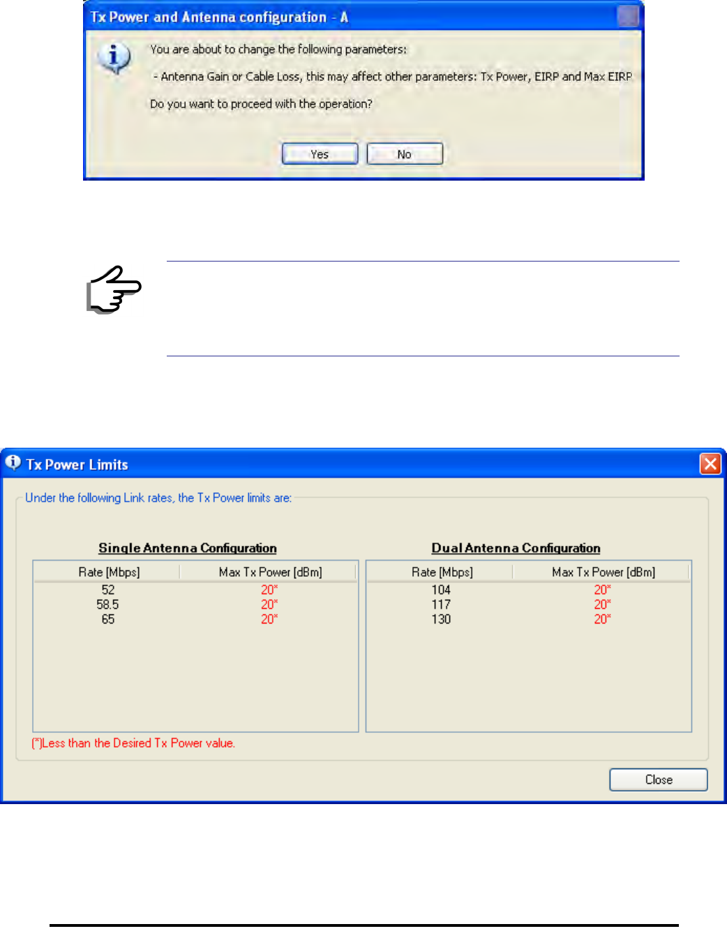
Considerations for Changing Antenna Parameters Chapter 4
RADWIN 1000/2000/5000 User ManualVersion 2.5.30p3 4-24
3. Set the Antenna Gain and Cable Loss. If do this you will receive a warn-
ing message:
Figure 4-17: Antenna parameters change warning
If inequality (*) above is violated, then the following warning window is
displayed:
Figure 4-18: Tx Power Limits
The precise relationship between the items in inequality (*) and the win-
dow of figure 4-16 is follows:
Note
• The Max EIRP level will be automatically set according to the selected
band and regulation.
• The EIRP level is the sum of the System Tx power and the Antenna
Gain minus the Cable Loss.
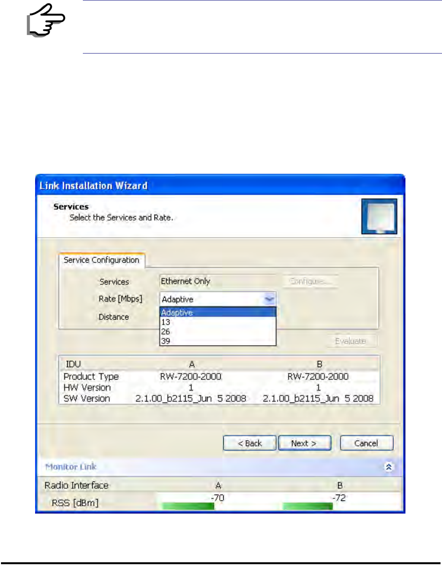
Installing the Link: Step 5, Services Chapter 4
RADWIN 1000/2000/5000 User ManualVersion 2.5.30p3 4-25
• Required Tx Power (per radio) will be adjusted down to the
lesser of the value entered and maxAllowedTxPower
• TxPower (system)is maxAllowedTxPower + 3 (for 2 radios)
• Max EIRP is maxRegEIRP.
• EIRP is maxAllowedTx Power + Antenna Gain - Cable
Loss
The table in figure 4-18 only shows rates where the maximum Tx
Power is the limitation, rather than regulations.
When you close the window of figure 4-18, the change you requested
will not be honored, and you will need to try again.
4. When you are finished with Tx Power configuration, Click Next.
Installing the Link: Step 5, Services
The Services dialog appears:
Figure 4-19: Services and Rates dialog
Note
Recall that maxAllowedPower and maxEIRP are regulatory. In an
unregulated environment, the only limit is maxODUTxPower.
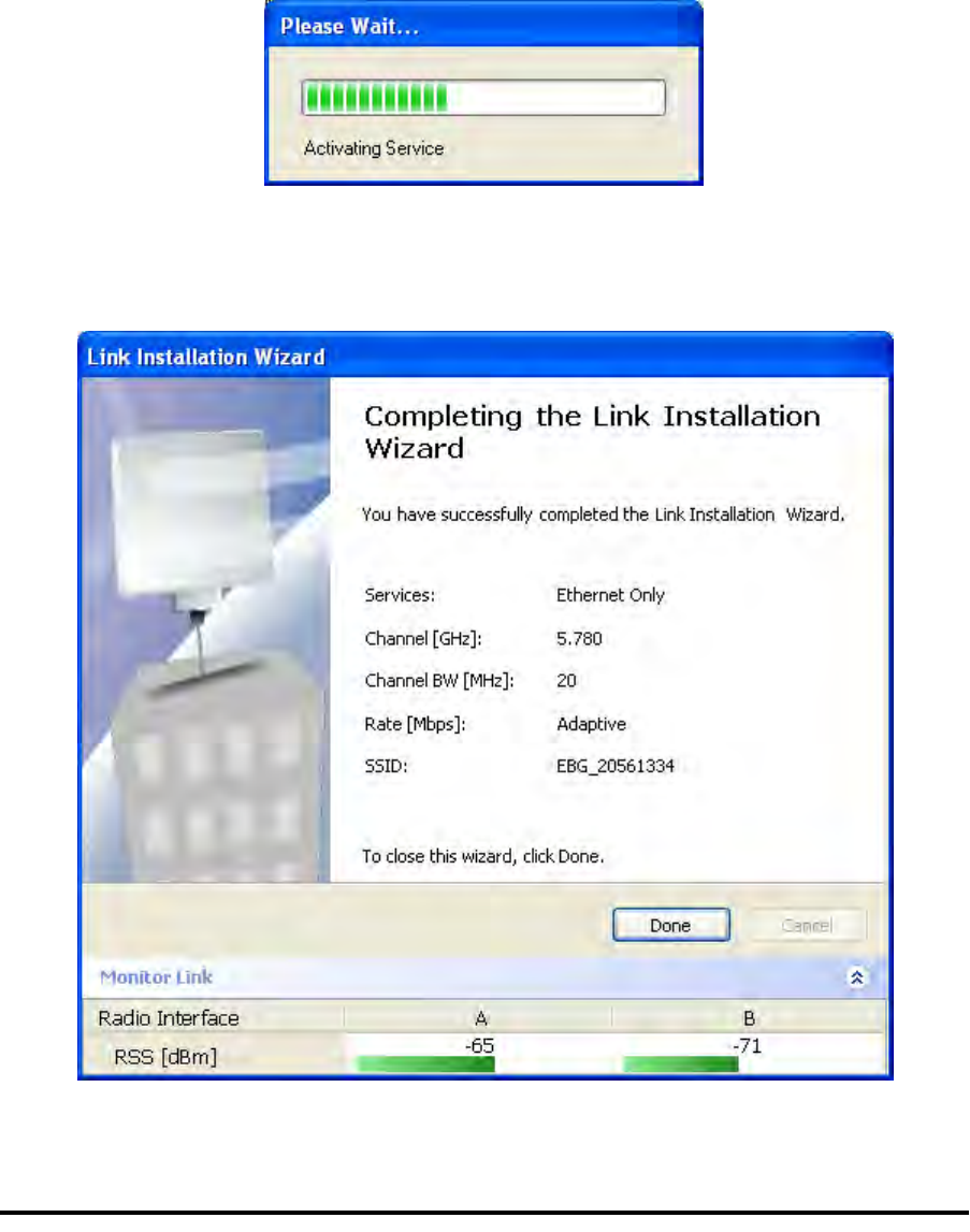
Installing the Link: Step 6, Installation Summary and Exit Chapter 4
RADWIN 1000/2000/5000 User ManualVersion 2.5.30p3 4-26
For version 2.1, Ethernet Only is the only available service. You may choose
a specific modulation rate or use Adaptive.
To choose a modulation rate:
1.Choose Adaptive or one of the available rate (see page 1-4 for informa-
tion about Automatic Adaptive Rate).
2. Click Next to continue.
The service is activated as show below:
Installing the Link: Step 6, Installation Summary and Exit
Figure 4-20: Installation Wizard Exit Summary
Click Done to return to the main window.
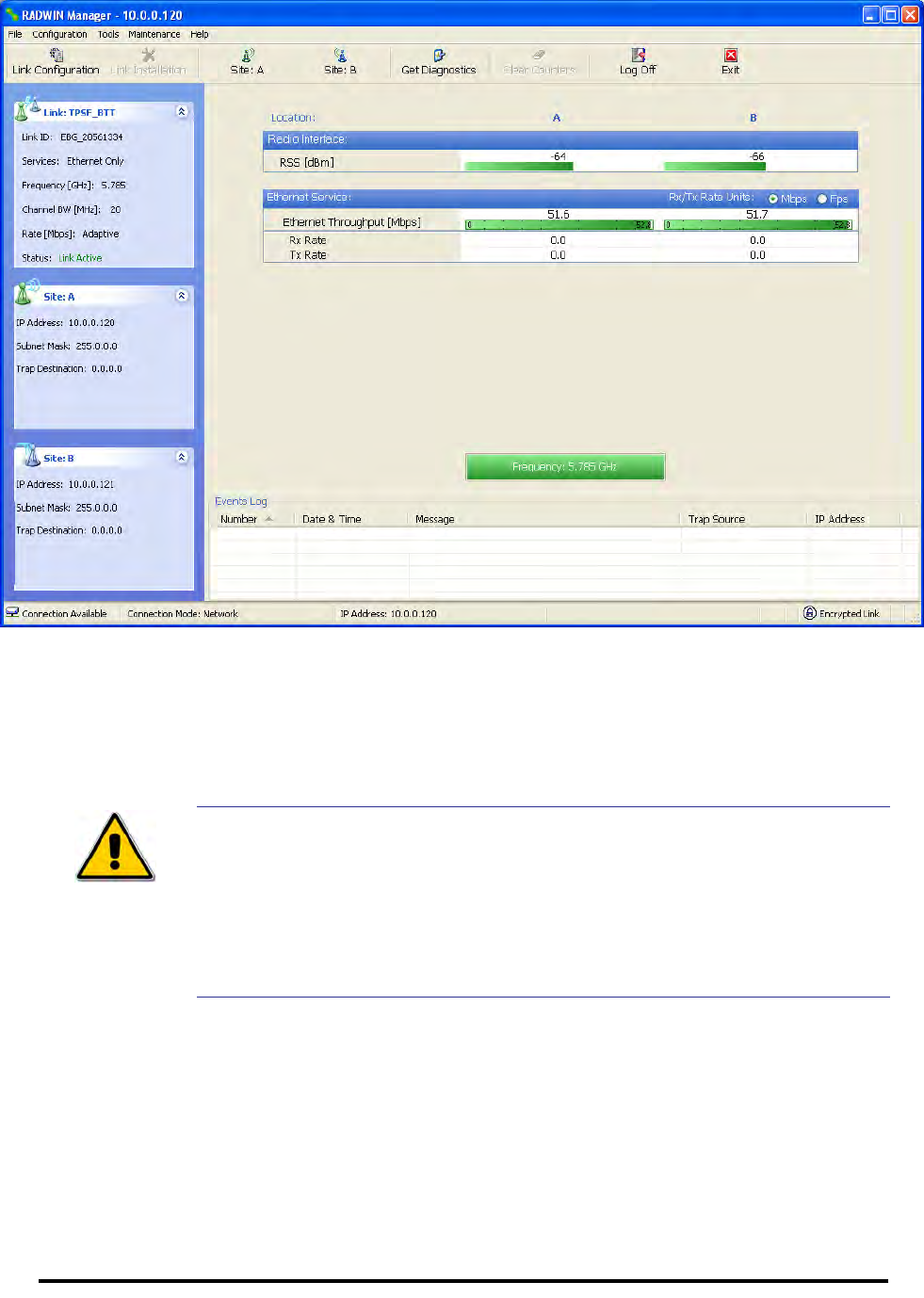
Installing the Link: Step 6, Installation Summary and Exit Chapter 4
RADWIN 1000/2000/5000 User ManualVersion 2.5.30p3 4-27
The main window now reflects the installation:
Figure 4-21: Main window of the manager after installation
To verify the installation:
• Verify that the Radio Signal Strength (RSS) is according to expected
results as determined by the Link Budget Calculator.
Caution
Installation mode, as described above, may be re-entered using
Configuration | 1 Configure Site A and Installation Mode the Site
Configuration dialog. Some Installation mode functionality may cause a
break in link service.
If you can accomplish link changes without breaking the service, always
prefer to use Configuration mode, described in chapter 5.

RADWIN 1000/2000/5000 User ManualVersion 2.5.30p3 5-1
Chapter 5
Configuring the Link
This chapter describes the link configuration procedure, which is performed
after the installation of both sides of the RADWIN 1000/2000/5000 link, as
set out in chapters 3 and 4.
Link configuration uses a Link Configuration Wizard to redefine the configu-
ration parameters and fine-tune an operational link. Both sides of the link
are configured simultaneously.
The following parameters are configured using the Link Configuration Wiz-
ard:
• System parameters
• Channel settings
• Transmission power and antenna settings
• Service parameters
Link Configuration: Getting Started
The Main Window of the RADWIN Manager
Ensure that the RADWIN Manager is running.
The main window should look similar to that in figure 5-1:
The RADWIN Manager Toolbar Chapter 5
RADWIN 1000/2000/5000 User ManualVersion 2.5.30p3 5-2
.
Figure 5-1: Main window, Wireless Link is Active
Before starting a configuration session, make sure that a communication
link exists between the two sides of the link.
The Link Status indication bar must be green. In the Link Status panel, the
Status field should show Link Active in green.
The main window of the RADWIN Manager contains a large amount of
information about the link. Before proceeding to details of link configuration
we set out the meaning of each item in the main window.
The RADWIN Manager Toolbar
In configuration mode, the RADWIN Manager toolbar contains the following
buttons:
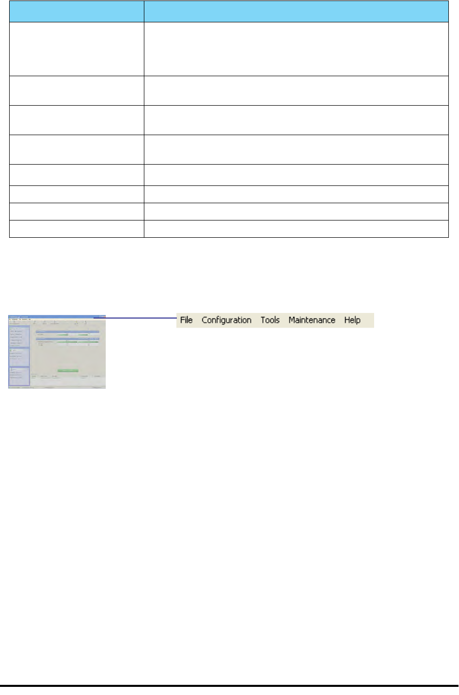
The RADWIN Manager Main Menu Chapter 5
RADWIN 1000/2000/5000 User ManualVersion 2.5.30p3 5-3
The RADWIN Manager Main Menu
The RADWIN Manager menu, is shown in table 5-2 below:
Table 5-1: RADWIN Manager Toolbar
Item Description
Link Configuration Changes configuration parameters of an operating wireless link;
assigns text files for storing alarms, statistics and configuration
data. This button is disabled until a link installation has
been completed
Link Installation Performs preliminary configuration of the system. This button is
disabled after the link is installed
Site: <Site 1 name> Opens the Site configuration dialog for Site A. Same as
Configuration | 1 Configure <Site 1 name>
Site: <Site 2 name> Opens the Site configuration dialog for Site B. Same as
Configuration | 2 Configure <Site 2 name>
Get Diagnostics Obtain system information
Clear Counters Disabled
Log off Closes the current session and logs off RADWIN Manager
Exit Exits RADWIN Manager

The RADWIN Manager Main Menu Chapter 5
RADWIN 1000/2000/5000 User ManualVersion 2.5.30p3 5-4
Table 5-2: RADWIN Manager main menu functionality
Menu level Function Reference
Top +1 +2
File
Log Off Return to Log On dialog.
Same as Log Off button
Exit Exit the manager. Same as
Exit button
Configuration
Link
Configuration Run the Configuration Wiz-
ard. Not available in
installation mode
1 Configure
<Site 1 name> Provides limited configura-
tion for site. Has a path to
return to installation
mode
2 Configure
<Site 2 name> Provides limited configura-
tion for site. Has a path to
return to installation
mode
Installation Runs the Installation Wiz-
ard. Not available in
configuration mode
Tools
Performance
Monitoring
Report
Active Alarms
1 <Site 1 name> Shows active alarms for
<Site 1 name>
2 <Site 2 name> Shows active alarms for
<Site 1 name>
Change
Password Change the Log On pass-
word dialog page 4-7
Events Log page 7-10
Clear Events Clear local events log
Save to File Save events log file
Preferences Local preferences dialog

The RADWIN Manager Main Menu Chapter 5
RADWIN 1000/2000/5000 User ManualVersion 2.5.30p3 5-5
Maintenance
Clear counters Disabled
Loopbacks Disabled
Reset
1 <Site 1 name> Reset <Site 1 name> ODU
2 <Site 2 name> Reset <Site 2 name> ODU
Help
RADWIN
Manager Help View online version of the
User Manual
Link Budget
Calculator Calculator opened in
default browser Appendix D
Get Diagnostics
Information Obtain system information page 7-1
About RADWIN
Manager Manager build and system
information
Table 5-2: RADWIN Manager main menu functionality (Continued)
Menu level Function Reference
Top +1 +2
Elements of the RADWIN Manager Main Window Chapter 5
RADWIN 1000/2000/5000 User ManualVersion 2.5.30p3 5-6
Elements of the RADWIN Manager Main Window
Link details pane
The Link details pane on the left is split into three sections. The top section
summarizes information about the link:
The two lower panels show basic link site details:
Table 5-3: Link Details
Item
Link ID
Services selected
Frequency
Channel bandwidth
Rate
Link status
Elements of the RADWIN Manager Main Window Chapter 5
RADWIN 1000/2000/5000 User ManualVersion 2.5.30p3 5-7
Monitor pane
he monitor pane, is the main source of real time information about link per-
formance at both link sites. It includes the following panes (top to bottom):
• Radio Interface, Received Signal Strength (RSS) in dBm
• Ethernet Service:
• Ethernet Throughput: The numbers are the current calculated
throughputs at each site. The colored bars (with numbers) indi-
cate the maximum possible throughput having regard for air
conditions.
• Rx and Tx Rates: Actual Ethernet traffic received and transmit-
ted rates per site, in Mbps of Fbps.
Table 5-4: Link site details, Site A and Site B
Item
IP Address
Subnet Mask
Trap Desalination
Elements of the RADWIN Manager Main Window Chapter 5
RADWIN 1000/2000/5000 User ManualVersion 2.5.30p3 5-8
Figure 5-2: Ethernet Bandwidth Indication
• Frequency box: It shows the link frequency. The color of the box
indicates the status
•Green is an active link
•Red is an inactive link
•Magenta shows an authentication or compatibility problem
•Brown shows severe compatibility problem
Events Log
The Events Log, stores alarms generated from both sides of the link and is
detailed in chapter 7, The Events Log.
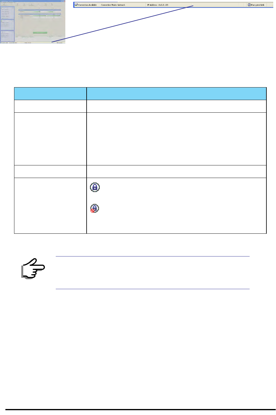
Elements of the RADWIN Manager Main Window Chapter 5
RADWIN 1000/2000/5000 User ManualVersion 2.5.30p3 5-9
Status Bar
The Status bar, displays the following icons:
Table 5-5: Status bar indicators
Icon or Label Purpose
Connectivity Shows if RADWIN Manager is communicating with the ODU.
Connection available
Connection mode to the ODU
• Over-the-Air connection - using the IP address of the
remote unit.
• Local connection - direct connection to the IDU without
using an IP address.
• Network connection - through a LAN
IP Address Login IP address
Encryption indicator
Normally encrypted link
Link password validation failed. The link is encrypted with
default keys. Service and configuration are unavailable. Change
the link password.
Note
There are several “floating” icons, which appear under specific
conditions
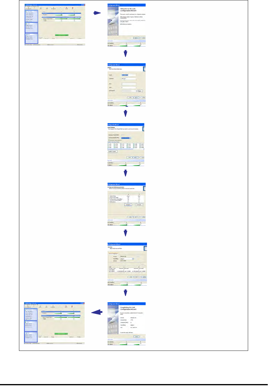
Configuring the Link: Overview Chapter 5
RADWIN 1000/2000/5000 User ManualVersion 2.5.30p3 5-10
Configuring the Link: Overview
The Configuration Wizard has seven steps as shown in table 5-6 below.
Table 5-6: Link Configuration Wizard
1Wizard welcome
2System parameters
• Link ID
• Site details
3Channel settings
4Tx power settings
5Services
6Wizard summary and
completion
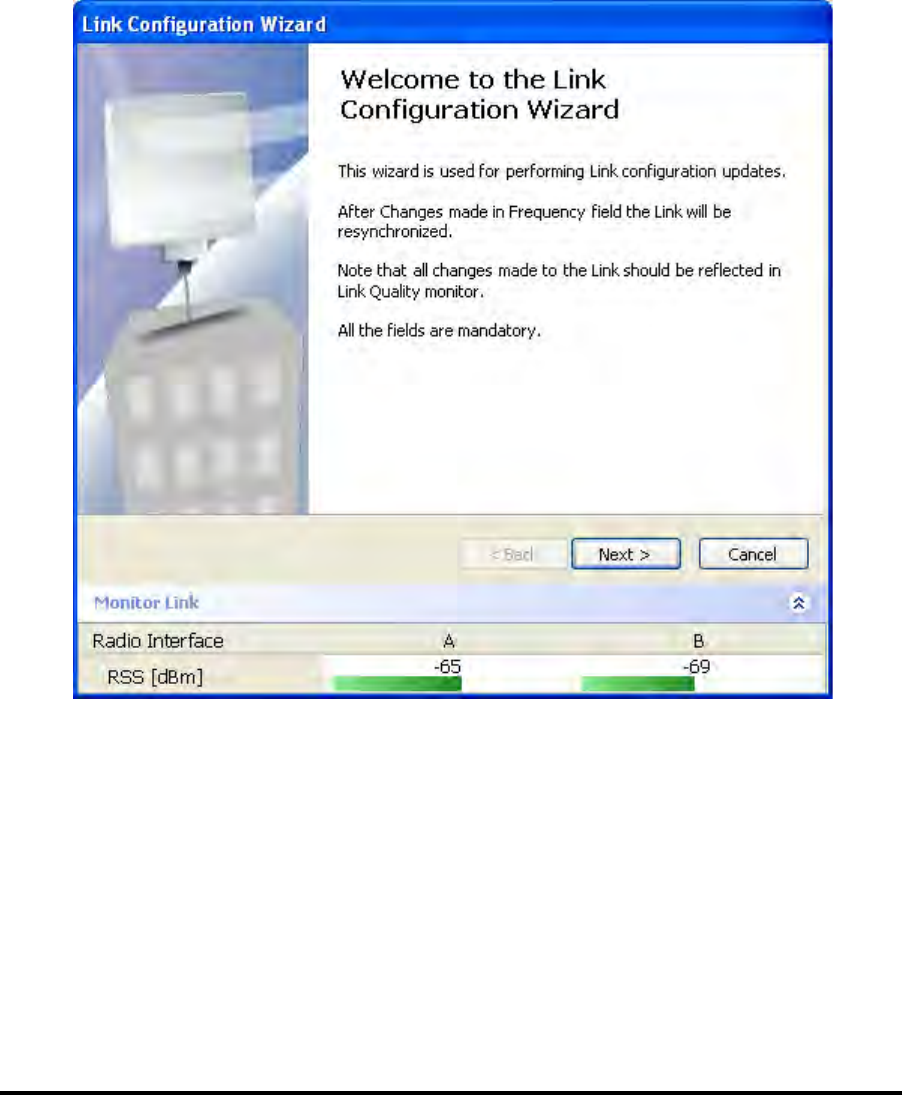
Configuring the Link: Step 1, Start the Wizard Chapter 5
RADWIN 1000/2000/5000 User ManualVersion 2.5.30p3 5-11
Since configuration functionality is included in the installation, we will briefly
review the main steps and for most part offer references to the correspond-
ing installation step.
Configuring the Link: Step 1, Start the Wizard
In the tool bar of the RADWIN Manager main window, click the Link Con-
figuration button. The Link Configuration button is only accessible on a
fully installed link as set out in chapter 4.
The Configuration Wizard opens:
Figure 5-3: Link Configuration Wizard
Click Next to proceed with the configuration procedure.
Configuring the Link: Step 2, System Parameters
The System dialog box opens:
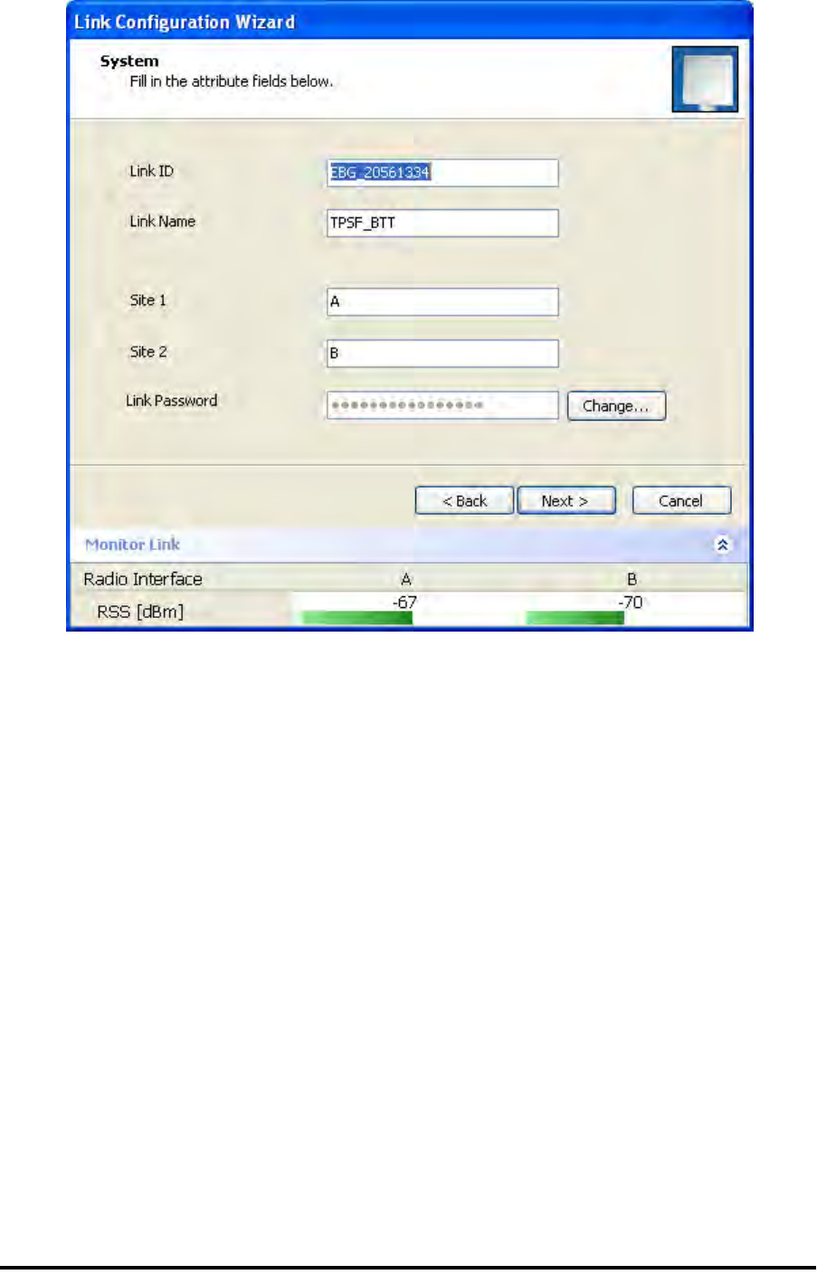
Configuring the Link: Step 3, Channel Settings Chapter 5
RADWIN 1000/2000/5000 User ManualVersion 2.5.30p3 5-12
Figure 5-4: Configuration Wizard, System dialog box
The System attributes may be edited and the Link Password may be
changed exactly as in the corresponding Link Installation step on page 4-
14.
Click Next to continue.
Configuring the Link: Step 3, Channel Settings
Configuring the Channel Settings follows the same pattern as the Installa-
tion procedure:
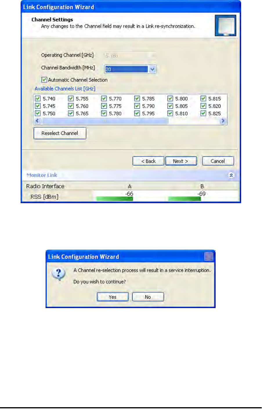
Configuring the Link: Step 3, Channel Settings Chapter 5
RADWIN 1000/2000/5000 User ManualVersion 2.5.30p3 5-13
Figure 5-5: Channel Settings dialog box - Automatic Channel Selection
Notice that the operating channel is grayed out. If you use the Reselect
Channel button, to change it, you will be asked for confirmation:
If you accept, then the system will search for the best operating channel:
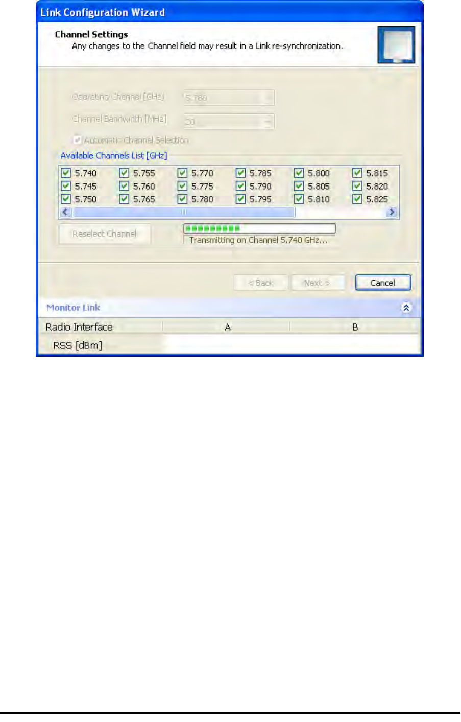
Configuring the Link: Step 3, Channel Settings Chapter 5
RADWIN 1000/2000/5000 User ManualVersion 2.5.30p3 5-14
Figure 5-6: Searching for the best operating channel
The link will return to the status of figure 5-5 above with a possible
change to the operating channel.
If you work without automatic channel selection, the Channel Settings win-
dow looks like this:
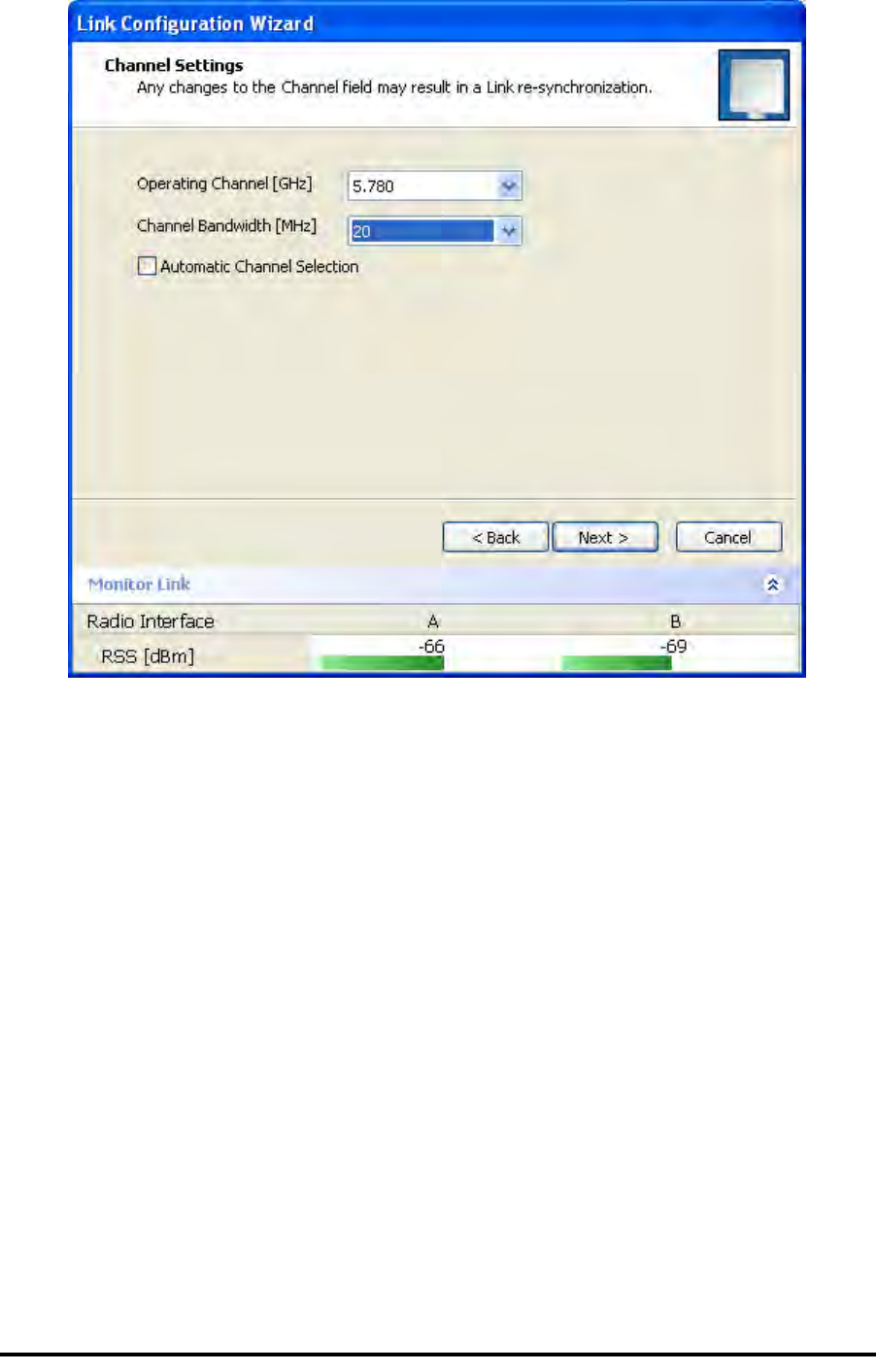
Configuring the Link: Step 3, Channel Settings Chapter 5
RADWIN 1000/2000/5000 User ManualVersion 2.5.30p3 5-15
Figure 5-7: Channel Settings without automatic channel selection
If you click the Operating Channel drop-down list, the following window
appears:
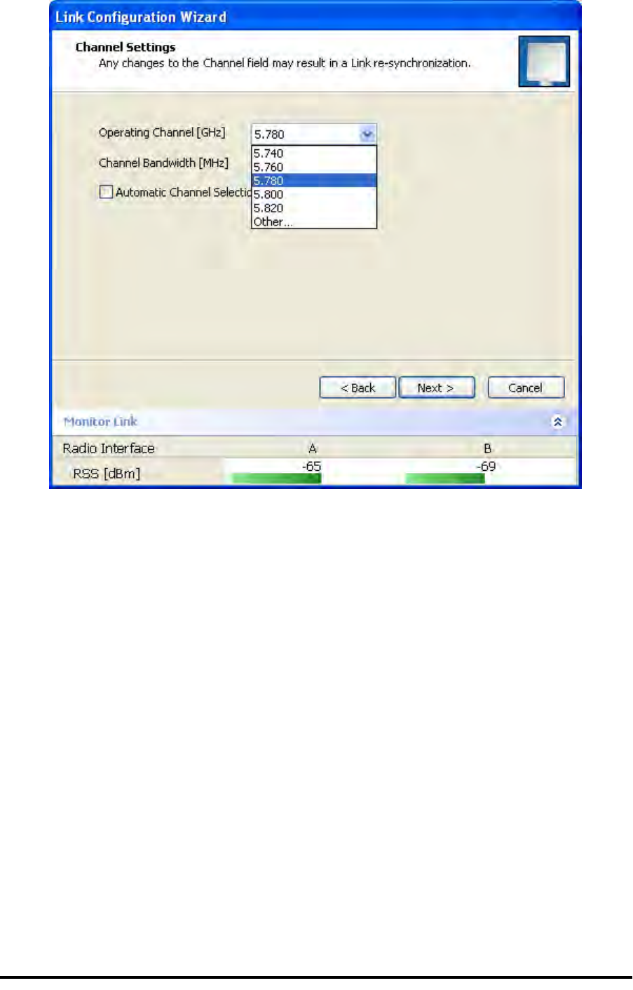
Configuring the Link: Step 3, Channel Settings Chapter 5
RADWIN 1000/2000/5000 User ManualVersion 2.5.30p3 5-16
Figure 5-8: Channel frequency options
Selecting one of the frequencies presented returns you to the status of
figure 5-7 with the appropriate change. If you choose Other..., the follow-
ing window opens:
Configuring the Link: Step 3, Channel Settings Chapter 5
RADWIN 1000/2000/5000 User ManualVersion 2.5.30p3 5-17
Figure 5-9: Choosing an “Other” Operating Channel frequency
The right hand drop-down list (showing 5.800) allows you to fine-tune the
frequency in increments of ±5MHz within a range of 5.740 - 5.835 GHz.
When you have completed making your choice, click Next to continue.
Configuring the Link: Step 4, Tx Power and Antenna Settings Chapter 5
RADWIN 1000/2000/5000 User ManualVersion 2.5.30p3 5-18
Configuring the Link: Step 4, Tx Power and Antenna
Settings
.
Figure 5-10: Transmission Power and Antenna Parameters
If you chose to configure either antenna, you are presented with the follow-
ing window:
Configuring the Link: Step 4, Tx Power and Antenna Settings Chapter 5
RADWIN 1000/2000/5000 User ManualVersion 2.5.30p3 5-19
Figure 5-11: Antenna configuration dialog with opened type selection
So far, the procedure duplicates the corresponding Installation process on.
If you choose a different antenna type and click OK, you will receive the fol-
lowing cautionary message:
Caution
In this context, entering Installation mode causes a service break until it is
restored by running the Installation wizard.
If you are uncertain, do not do this without expert technical
assistance.
Configuring the Link: Step 5, Services Chapter 5
RADWIN 1000/2000/5000 User ManualVersion 2.5.30p3 5-20
You may also change the Required Tx Power, Antenna Gain and Cable Loss.
The procedure is the same as that set out in the Installation procedure on
page 4-23.
When you have completed making your choice, proceed to the Services
window.
Configuring the Link: Step 5, Services
Here is the services dialog:
.
Figure 5-12: Services and Rates dialog
To choose Services, see the corresponding Installation procedure on
page 5-20.
Click Next to continue.
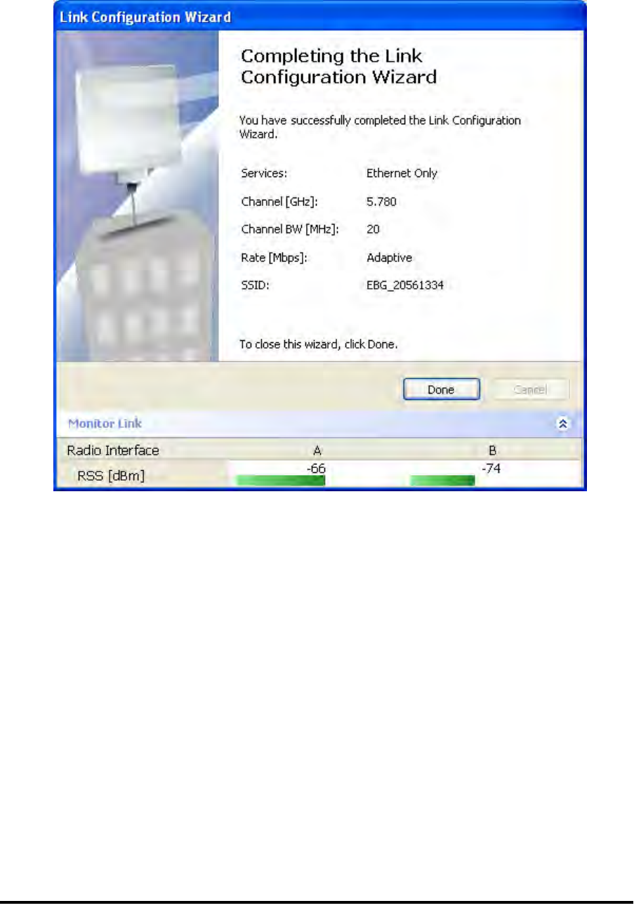
Configuring the Link: Step 6, Configuration Summary and Exit Chapter 5
RADWIN 1000/2000/5000 User ManualVersion 2.5.30p3 5-21
Configuring the Link: Step 6, Configuration Summary and
Exit
Figure 5-13: Configuration Wizard Exit Summary
Click Done to return to the main window.
The main window now reflects the configuration:
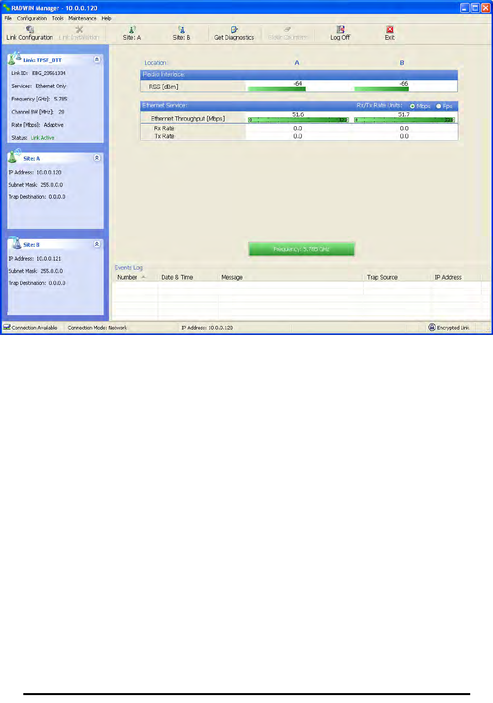
Configuring the Link: Step 6, Configuration Summary and Exit Chapter 5
RADWIN 1000/2000/5000 User ManualVersion 2.5.30p3 5-22
Figure 5-14: Main window of the manager after configuration

RADWIN 1000/2000/5000 User ManualVersion 2.5.30p3 6-1
Chapter 6
Site Configuration
The Site Configuration dialog panels are used to configure parameters,
which may differ between both sides of the link.
The parameters configured using the Site Configuration dialog panels
include (among others):
• System settings
• Air interface - Transmit (Tx) power and antenna
• Network management including VLAN
• Security settings
• Date and time
• Hub or Bridge mode
In addition, the Link Site Configuration panels include several information
windows:
• Inventory - link hardware and software model details
• External alarms indicators
The Operations dialog offers a “doorway” to jump into installation mode
reverting to factory settings.
The Site Configuration dialog has its own main menu with the following
extra functionality:
• Backup configuration parameters to a text file
• Restore configuration from a previously backed up configuration file
• Enable/disable the site ODU buzzer
• Jump back into installation mode keeping current configuration set-
tings
Configuring the Site
Editing the Configuration Parameters by Site
You can edit the configuration parameters for each site individually. The fol-
lowing functions are available from the left side of the dialog box.
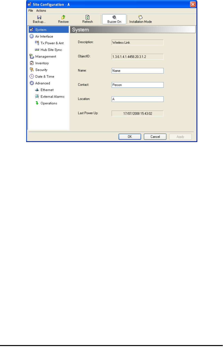
Editing the Configuration Parameters by Site Chapter 6
RADWIN 1000/2000/5000 User ManualVersion 2.5.30p3 6-2
Figure 6-1: Configuration Dialog Box
Functions on the left of the dialog box:
Functions at the top of the dialog box:
System Edit the contact person and location details.
View the system details
Air Interface Change the transmit power, cable loss, antenna
type and settings
Inventory View the hardware and software inventory
(release numbers, model identification, MAC
address)
Management Configure the IP address, Subnet Mask, Default
Gateway, the Trap Destination and VLAN
Security Change the Community Values and the Link
Password
Date and Time Set the date and time of the link from an NTP
servers otherwise
Advanced Choose Hub or Bridge ODU mode, set the
Ethernet ports configuration, set the external
alarm inputs, restore factory settings
Backup Save the current configuration to an .ini file
Restore Restore the link configuration from the .ini file
created by the backup
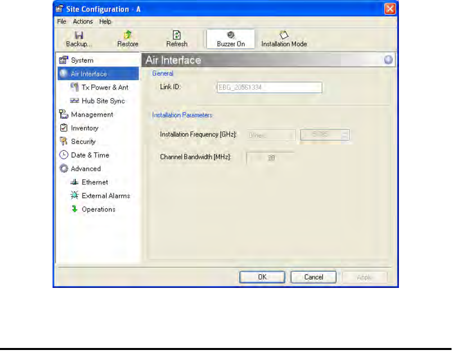
Viewing Air Interface Details Chapter 6
RADWIN 1000/2000/5000 User ManualVersion 2.5.30p3 6-3
To edit the Configuration Parameters:
1. Click the required site button on the main tool bar of the RADWIN Man-
ager
OR
Click Configuration from the main menu and choose a site to config-
ure.
The Configuration dialog box opens (see figure 6-1 above).
2. Choose the appropriate item in the left hand list to open a dialog box.
3. Click Apply to save changes.
In subsequent instructions, we will simply say “Choose a site to configure”
on the understanding that the foregoing procedure is implied.
Viewing Air Interface Details
Click the Air Interface item in the left hand list. A window similar to the fol-
lowing appears:
Figure 6-2: Air interface details
Installation
Mode Return to Installation Mode for the entire link.
Selecting the Mute check box before clicking
the Install Mode button mutes the Beeper.
Mute Mutes the alignment tone in installation mode.
Reactivate the beeper during alignment.
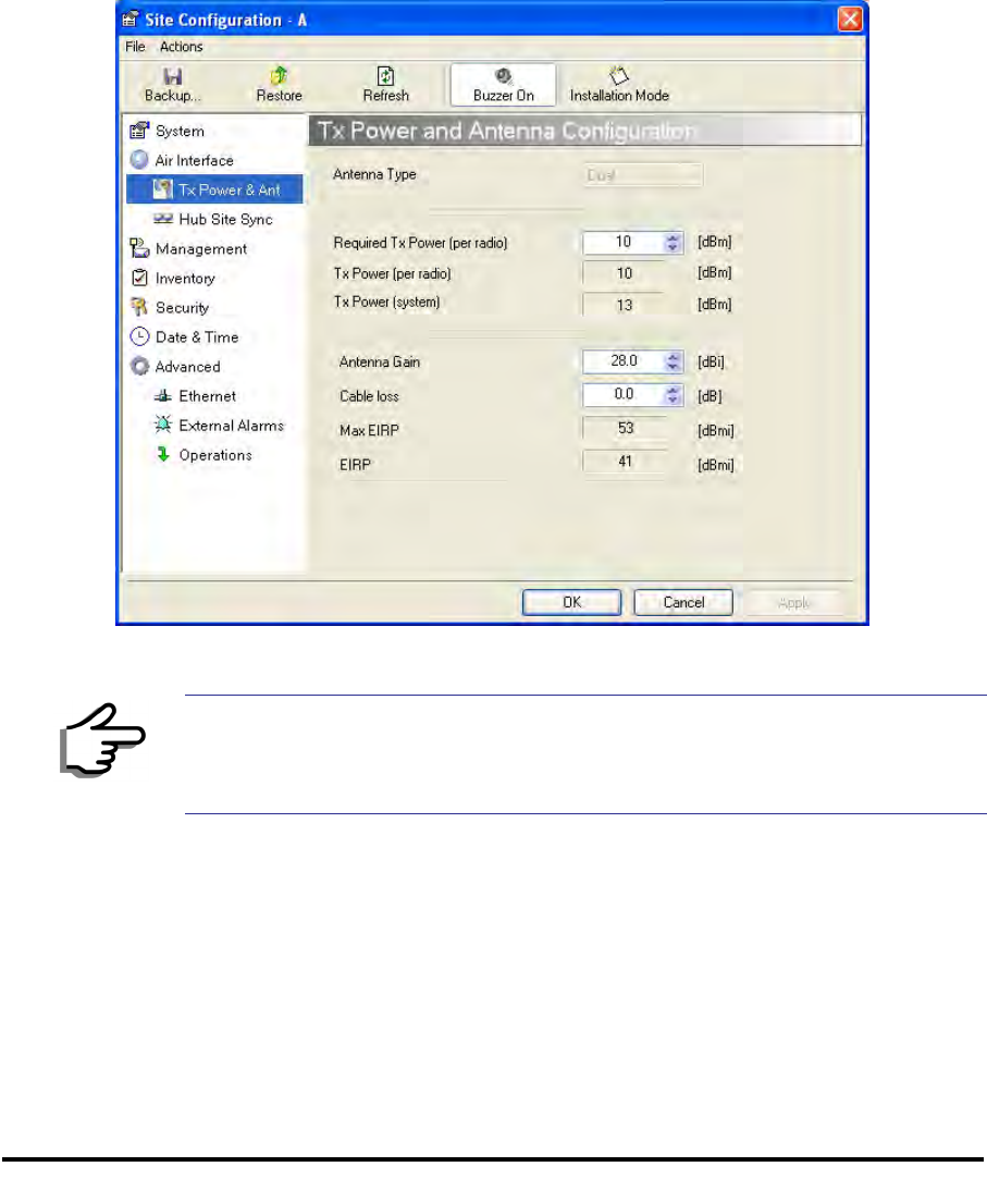
Changing the Transmit Power Chapter 6
RADWIN 1000/2000/5000 User ManualVersion 2.5.30p3 6-4
Changing the Transmit Power
Each site can have a different transmit power level.
To change the Transmit Power:
1. Choose a site to configure.
The Configuration dialog box opens.
2. Choose Air Interface (see figure 6-3).
3. Choose the required Transmit (Tx) Power Level.
4. Click Apply to save the changes.
Figure 6-3: Changing the Transmit Power
Site Management: IP Address and VLAN
Configuring the ODU Address
Each site must be configured separately, first site A then site B.
To define the Management Addresses:
1. Choose a site to configure.
Note
The same considerations apply here as were noted in the Installation
procedure on page 4-23.
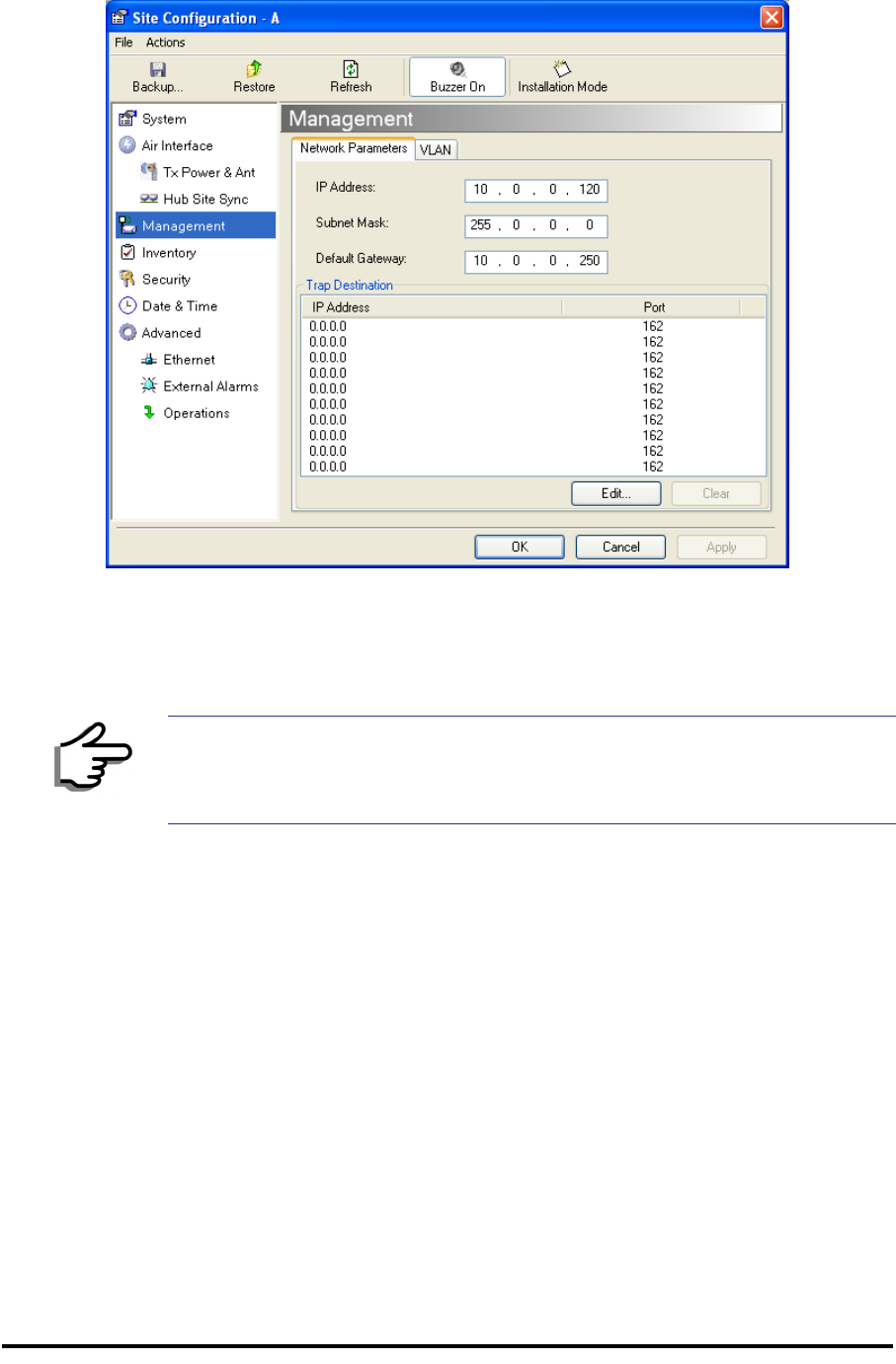
Configuring VLAN Settings Chapter 6
RADWIN 1000/2000/5000 User ManualVersion 2.5.30p3 6-5
The Configuration dialog box opens:
Figure 6-4: Management Addresses - Site Configuration dialog box
5. Choose Management.
6. Enter the IP address of the ODU in the IP Address field.
7. Enter the Subnet Mask.
8. Enter the Default Gateway.
9. Enter the Trap Destination. This could be the IP address of the managing
computer. The events log will be stored at this address.
10.Click Apply to save the changes.
Configuring VLAN Settings
VLAN Management enables separation of user traffic from management
traffic whenever such separation is required. It is recommended that both
sides of the link be configured with different VLAN IDs for management traf-
fic.
To enable VLAN management:
1. Click Configuration from the main menu.
Note
If performing configuration from the RADWIN Manager, the IP address is
that entered from the login screen.
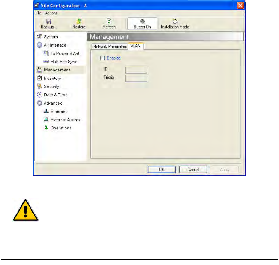
Configuring VLAN Settings Chapter 6
RADWIN 1000/2000/5000 User ManualVersion 2.5.30p3 6-6
2. Choose a site to configure. If you are configuring both sites, choose site
B first.
3. Choose Management.
4. Open the VLAN tab.
5. Check the Enabled box.
6. Enter a VLAN ID. Its value should be between 1 and 4094.
After entering the VLAN ID, only packets with the specified VLAN ID are
processed for management purposes by the ODU. This includes all the
protocols supported by the ODU (ICMP, SNMP, TELNET and NTP). The
VLAN priority is used for the traffic sent from the ODU to the managing
computer. Using VLAN for management traffic affects all types of man-
agement connections (local, network and over the air).
7. Enter a Priority number between 0 and 7.
8. Change the VLAN ID and Priority of the managing computer NIC to be
the same as those of steps 6 and 7 respectively.
9. Click Apply or OK.
Figure 6-5: Configuring management traffic VLAN Settings
Caution
Changing this parameter causes the RADWIN Manager to immediately
disconnect.To avoid inconvenience, you should verify the change by
setting the VLAN only to one ODU, and only after verifying proper
management operation, change the other ODU VLAN setting.

Setting the Date and Time Chapter 6
RADWIN 1000/2000/5000 User ManualVersion 2.5.30p3 6-7
Lost or forgotten VLAN ID
If the VLAN ID is forgotten or there is no VLAN traffic connected to the
ODU, then reset the relevant ODU.
During the first two minutes of connection to the ODU uses management
packets both with and without VLAN. You may use this period to reconfigure
the VLAN ID and priority.
Setting the Date and Time
The ODU maintains a date and time. The date and time should be synchro-
nized with any Network Time Protocol (NTP) version 3 compatible server.
During power-up the ODU attempts to configure the initial date and time
using an NTP Server. If the server IP address is not configured or is not
reachable, a default time is set.
When configuring the NTP Server IP address, you should also configure the
offset from the Universal Coordinated Time (UTC). If there is no server
available, you can either set the date and time, or you can set it to use the
date and time from the managing computer. Note that manual setting is not
recommended since it will be overridden by a reset, power up, or synchroni-
zation with an NTP Server.
To set the date and time
1. Determine the IP address of the NTP server to be used.
2. Test it for connectivity using the command (Windows XP), for example:
w32tm /stripchart /computer:216.218.192.202
You should get a continuous response of times, each a few seconds
apart.
3. Choose a site to configure.
The Configuration dialog box opens.
4. Choose Date & Time:
Note
The NTP uses UDP port 123. If a firewall is configured between the ODU
and the NTP Server this port must be opened.
It can take up to 8 minutes for the NTP to synchronize the ODU date and
time.
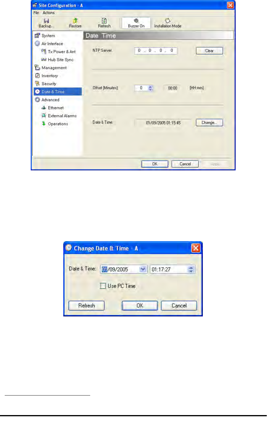
Setting the Date and Time Chapter 6
RADWIN 1000/2000/5000 User ManualVersion 2.5.30p3 6-8
Figure 6-6: Date and Time Configuration
5. If entering an IP address for the NTP Server, click Clear, and then enter
the new address.
6. Set your site Offset value in minutes ahead or behind GMT1.
7. To manually set the date and time, click Change and edit the new values.
Figure 6-7: Change Date and Time
If you used an NTP Server, you will see a window like this:
1. Greenwich Mean Time
Ethernet Properties Chapter 6
RADWIN 1000/2000/5000 User ManualVersion 2.5.30p3 6-9
Figure 6-8: Date and Time configured from an NTP Server
8. Click OK to return to the Configuration dialog.
Ethernet Properties
Configuring the Bridge
Bridge configuration is required in various network topologies, such as pro-
tection (1+1) and ring applications. The bridge configuration parameters
are located under the Advanced tab of the Site Configuration dialog box:
Configuring the Bridge Chapter 6
RADWIN 1000/2000/5000 User ManualVersion 2.5.30p3 6-10
Figure 6-9: Bridge Configuration - Site Configuration dialog box
ODU Mode
This parameter controls the ODU mode with two optional values,
• Hub Mode - in Hub mode the ODU transparently forwards all packets
over the wireless link.
• Bridge Mode - In Bridge mode the ODU performs both learning and
aging, forwarding only relevant packets over the wireless link. The
aging time of the ODU is fixed at 300 seconds.
IDU Aging time
This parameter controls the IDU aging time.
The aging time parameter controls the time after which each MAC address
is dropped from the MAC address learning table.
The default value is 300 seconds.
Note
Changing these modes requires system reset.
Note
• Any change to these parameters is effective immediately.
• Each side of the link can be configured separately.

Configuring Ethernet Ports Mode Chapter 6
RADWIN 1000/2000/5000 User ManualVersion 2.5.30p3 6-11
The following table shows the appropriate configuration for several common
scenarios. Both link sites must be configured with the same parameter:
Configuring Ethernet Ports Mode
The ODU Ethernet port is configured to auto-detect by default and may not
be changed.
The ODU Ethernet port mode is configurable for line speed (10/100BaseT)
and duplex mode (half or full duplex).
An Auto Detect feature is provided, whereby the line speed and duplex
mode are detected automatically using auto-negotiation. Use manual con-
figuration when attached external equipment does not support auto-negoti-
ation. The default setting is Auto Detect.
To configure the Ethernet Mode:
1. From the Configuration menu, choose the site to reconfigure.
The Site Configuration dialog box opens.
2. Click Advanced | Ethernet.
3. In the Ethernet Ports Configuration pane, use the drop-down menu to
choose the configuration.
Table 6-1: ODU mode configuration for common
Scenario ODU
Mode IDU Aging
Time
Standard (Default) Configuration for
Ethernet Applications Bridge 300 sec
Rapid network topology changes
where fast aging is required Hub 1 sec
Ethernet Hub Hub N/A
Ethernet Bridge Bridge N/A
Caution
You should not reconfigure the port that is used for the managing computer
connection, since a wrong configuration can cause a management
disconnection or Ethernet services interruption.

Setting the Maximum Information Rate Chapter 6
RADWIN 1000/2000/5000 User ManualVersion 2.5.30p3 6-12
4. Click Apply to save the changes.
Setting the Maximum Information Rate
The maximum Ethernet throughput of the link can be limited. The default
setting is Not Limited (see figure 6-9 above), where the highest informa-
tion rate available for the link conditions and settings is used.
To limit the Ethernet information rate:
1. From the Configuration menu, choose the site to reconfigure.
2. Click Advanced | Ethernet
The Configuration dialog box opens.
3. In the Information Rate pane, use the drop-down menu to choose the
maximum Information Rate.
4. Choose Other to define the throughput with 1 Kbps resolution
5. Choose Not Limited for the highest information rate possible for the
link conditions and settings
6. Click Apply to save the changes.
Displaying the Inventory
To view the inventory data
1. Choose a site from the main menu.
The Configuration dialog box opens.
2. Choose Inventory (figure 6-10).
Note
It is possible to close the Ethernet service by disconnecting the Ethernet
port.
If you close the port, you may subsequently be unable to access the
device. If this should occur, a workaround is as follows:
• Connect the system from the remote site
• Connect via other Ethernet port (of the IDU)
• Power down the equipment and connect immediately after power
up (the fastest way is to enter install mode)
Security Features Chapter 6
RADWIN 1000/2000/5000 User ManualVersion 2.5.30p3 6-13
Figure 6-10: Inventory Screen
Security Features
The Security dialog enables you to change the Link Password and the SNMP
Communities details:
Changing the Link Password Chapter 6
RADWIN 1000/2000/5000 User ManualVersion 2.5.30p3 6-14
Figure 6-11: Available security features
Changing the Link Password
This item is only available when the link is down. Otherwise, it works the
same way as the corresponding item on page 4-16.
RADWIN Manager Community Strings
The ODU communicates with the application using SNMPv1 protocol. The
protocol defines three types of communities:
• Read-Only for retrieving information from the ODU
• Read-Write to configure and control the ODU
• Trap used by the ODU to issue traps.
The Community string must be entered at login. The user must know the
password and the correct Community string to gain access to the system. A
user may have read-only privileges.
It is not possible to manage the ODU if the read-write or the read Commu-
nity values are forgotten. A new Community value may be obtained from
RADWIN Customer Support for the purpose of setting new Community; the
serial number or the MAC address of the ODU must be supplied.
Note
The RADWIN Manager uses the Read Community strings public for the site
Al ODU and public-remote for the site B ODU. It uses Write Community
strings netman for the site A ODU and netman-remote for the site B
ODU. These are the factory defaults.

RADWIN Manager Community Strings Chapter 6
RADWIN 1000/2000/5000 User ManualVersion 2.5.30p3 6-15
The read-write Community strings and read-only Community strings have a
minimum of five alphanumeric characters. (bru1 and bru4097 are not per-
mitted). Changing the trap Community is optional and is done by clicking
the check box.
Editing Community Strings
The Community change dialog box is available from the Configuration |
Security tab. Both read-write and read-only communities must be defined.
On logging on for the first time, use the following as the current Commu-
nity:
• For Read-Write Community, use netman.
• For Read-Only Community, use public.
• For Trap Community, use public
To change a Community string:
1. From the Configuration dialog box, choose the Security tab.
2. Type the current read-write Community (default is netman).
3. Choose the communities to be changed by clicking the check box.
4. Type the new Community string and re-type to confirm.
5. Click OK to save.
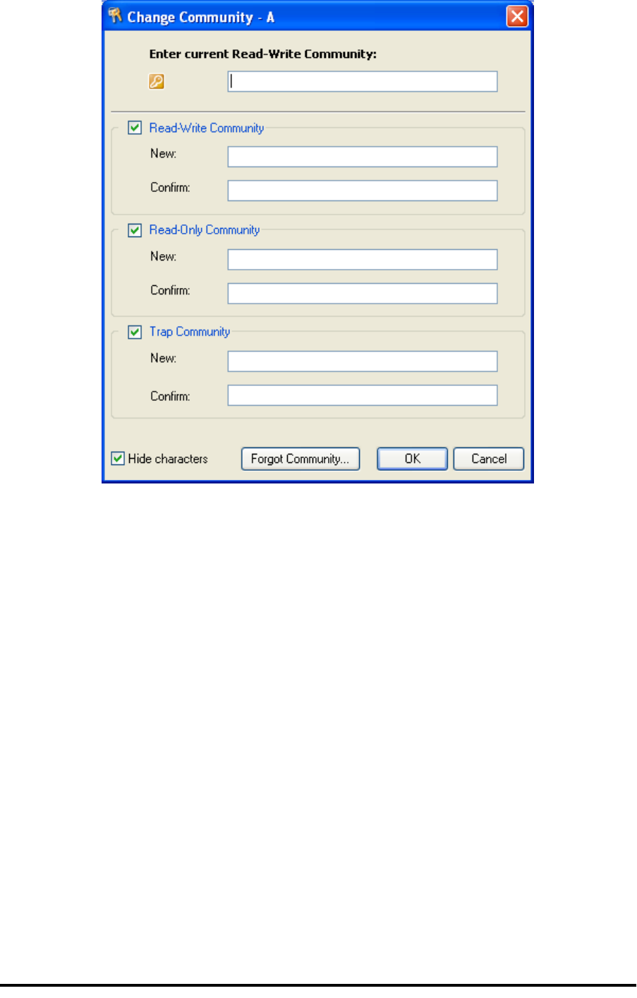
RADWIN Manager Community Strings Chapter 6
RADWIN 1000/2000/5000 User ManualVersion 2.5.30p3 6-16
Figure 6-12: Changing the Community String
Forgotten Community string
If the read-write Community string is unknown, an alternative Community
key can be used. The alternative Community key is unique per ODU and can
be used only to change the Community strings. The alternative Community
key is supplied with the product, and should be kept in a safe place.
If both the read-write Community and the alternative Community key are
unavailable, then an alternative Community key can be obtained from RAD-
WIN Customer Support using the ODU serial number or MAC address. The
serial number is located on the product label. The serial number and the
MAC address are displayed in the Site Configuration inventory tab.
When you have the alternative Community key, click the Forgot Commu-
nity button and enter the Alternative Community key (figure 6-13). Then
change the read-write Community string.

Muting the alignment tone Chapter 6
RADWIN 1000/2000/5000 User ManualVersion 2.5.30p3 6-17
Figure 6-13: Alternative Community Dialog box
Muting the alignment tone
The ODU alignment tone becomes audible as soon as power is supplied,
and continues until the ODUs are aligned and the link established.
It is possible to mute the tone during regular operation of the link. It must
be enabled when performing the alignment procedure.
To mute the alignment tone:
1. Choose a site.
2. The Configuration dialog box opens.
3. In the Configuration dialog box, click the Buzzer button. The button tog-
gles between on and off.
The tone is disabled.
To restore the alignment tone:
1. Choose a site.
The Configuration dialog box opens.
2. In the Configuration dialog box, click the Buzzer button. The button tog-
gles from on to off. The tone is enabled.
Setting External Alarm Inputs
The IDU-C has two external alarm inputs and two external alarm outputs in
the form of dry-contact relays. The Alarm interface is located on the front
panel of the IDU-C and is a 25-pin D-type female connector. see IDU-C
Alarm Connector on page B-3, for wiring specifications and pinout. The
user enables or disables each of the alarms and can configure the alarm
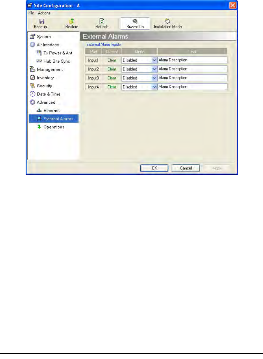
Managing Configuration Files Chapter 6
RADWIN 1000/2000/5000 User ManualVersion 2.5.30p3 6-18
description text that appears in the alarm trap. The ODU sends the alarm
within less than a second from actual alarm trigger.
To set the external alarm inputs:
1. Open the Site Configuration Alarms configuration by clicking Configura-
tion | Advanced.
Figure 6-14: External Alarm Configuration
2. Choose an alarm and set its mode to Enabled or Disabled
3. Enter a description of the alarms in the text field.
4. Click Apply to save.
5. Click OK to exit from the dialog.
Managing Configuration Files
Backup Configuration to a File
RADWIN Manager allows you to backup configuration parameters of the
local and remote units to the managing computer as .ini files. Each site is
backed up in a separate .ini file.
To save the configuration in a file:
1. Choose a site to back up.
The Configuration dialog box opens.

Restoring a Configuration File Chapter 6
RADWIN 1000/2000/5000 User ManualVersion 2.5.30p3 6-19
2. Click Backup.
3. In the Save As dialog box, indicate in which folder and under what name
configuration file is to be saved, and click Save.
Restoring a Configuration File
Configuration files (*.ini) can be uploaded from the managing computer.
Such configuration files can be distributed to other units that use the same
configuration.
To restore a configuration file:
1. Choose a site to restore (from a previous backup).
The Configuration dialog box opens.
2. Click Restore.
3. From the Open dialog box choose *.ini file to upload and click OK.
Resetting
You may reset the link, preserving the current configuration, or reset to fac-
tory defaults.
To reset the link preserving current configuration:
1. From Maintenance on the main window, reset the remote unit.
2. From Maintenance on the main window, reset the local unit.
To reset to Factory Defaults
1. Choose either of the sites.
The Configuration dialog box opens.
2. Choose Operations in the Configuration dialog box.
3. Click the Restore Defaults button.
A message box asking if you want to restore factory default appears.
4. Click the check box if you want to keep the current IP address settings.
5. Click Yes to continue.
Caution
Backup files are specific to a site (IDU / ODU pair and Link ID).
Do not restore a backup configuration file to a site other than that from
which it was originally taken.
Caution
Resetting the link causes service disconnection.
To maintain the connection between the managing computer and
the link, first reset Site B.

Configuration with Telnet Chapter 6
RADWIN 1000/2000/5000 User ManualVersion 2.5.30p3 6-20
Configuration with Telnet
A Telnet terminal can be used to configure and monitor the RADWIN 1000/
2000/5000.
To start a Telnet session, use telnet <manager IP>.
For example, if you run Telnet as follows,
telnet 10.0.0.120
you will be asked for a user name and password.
The login user name/password is identical to the Community strings; Read
allows display only, Read/Write allows display and set commands.
Supported Telnet commands are shown in table 6-2. Note that some of
the commands are model-specific. For example, TDM commands will not
apply to Ethernet only and PoE based links.
Table 6-2: Telnet Commands
Command Explanation
display inventory Displays ODU product name, Name, Location, hardware
and software revisions, uptime, MAC address, IDU product
name, IDU software and hardware revisions
display management Displays IP, Subnet, Gateway, Traps table
display link Displays State, Link ID, Channel BW, RSS, TSL,
Frequency/ACS, DFS, Rate/ARA, Distance
display Ethernet Displays Bridge Mode, Aging time, Port table (State, Status
and action)
display tdm Displays Clock Mode, Master Clock Mode, Current Clock,
Quality[1], TDM table (Line status, Error Blocks)
display ntp Displays Time, Server and Offset
set ip <ipaddr> <subnetMask>
<gateway> Set the ODU IP address, subnet mask and gateway
The user must reset the ODU after the command
completion
display PM
<interface:AIR,LAN1,LAN2,TDM1,
TDM2,TDM3,TDM4>
<interval:current,day,month>
Shows the performance monitor tables for each interface
according to user defined monitoring intervals
set trap <index:1-10> <ipaddr>
<port:0-65535> Set a specific trap from the traps table (set trap 3
10.0.0.133 162)
set readpw <oldpasswd> <passwd> Set the read access password (Read Community)
set writepw <oldpasswd> <passwd> Set the read-write access password (Read-Write
Community)
set trappw <oldpasswd> <passwd> Set the trap Community string
set buzzer <mode:0=OFF,1 =ON> Toggle the buzzer mode (0 – off, 1 – on)

Configuration with Telnet Chapter 6
RADWIN 1000/2000/5000 User ManualVersion 2.5.30p3 6-21
set tpc<power:Value between minimal
TX power, and maximal TX power> Set the ODU transmit power. If a wrong value is entered,
both min and max values shall be displayed in the error
reply
set bridge <mode:0=Bridging OFF,1=
Bridging ON > Set the ODU bridge mode (0 – off, 1 – on)
set name <new name> Set the name of the link
set location <new location> Set the name of the location
Set contact <new contact> Set the name of the site manager
set Ethernet <>port:MNG,LAN1,LAN2>
<mode:AUTO,10H,10F,100H,100F,DIS
ABLE>
Set the mode and speed of each ethernet port
Reboot Reset both the IDU and the ODU. The user shall be
prompt that the command will reset the card and that he
has to reconnect the telnet session after TBD seconds.
Help Displays the available commands
Table 6-2: Telnet Commands (Continued)
Command Explanation

Configuration with Telnet Chapter 6
RADWIN 1000/2000/5000 User ManualVersion 2.5.30p3 6-22
figure 6-15, below, shows the available Telnet commands via the Help
command.
Hello admin, welcome to ODU Management CLI!
+-----------------------------------------------------------+
Software Revision 2.1.00_b2070_Jun 5 2008
+-----------------------------------------------------------+
admin@10.0.0.120-> Type "help" for help.
admin@10.0.0.120-> help
display inventory
display management
display link
display ethernet
display tdm
display ntp
display PM <interface:AIR,LAN1,LAN2,TDM1,TDM2,TDM3,TDM4>
<interval:current,day,month>
set ip <ipaddr> <subnetMask> <gateway>
set trap <index:1-10> <ipaddr> <port:1-65535>
set readpw <writePasswd> <newPasswd>
set writepw <writePasswd> <newPasswd>
set trappw <writePasswd> <newPasswd>
set buzzer <mode:0=OFF,1=ON>
set tpc <power:Value between minimal TX power, and maximal TX power>
set bridge <mode:0=Bridging OFF,1=Bridging ON>
set name <new name>
set location <new location>
set contact <new contact>
set ethernet <port:MNG,LAN1,LAN2> <mode:AUTO,10H,10F,100H,100F,DISABLE>
reboot
help
Command "help" finished OK.
Figure 6-15: Telnet Management Screen

RADWIN 1000/2000/5000 User ManualVersion 2.5.30p3 7-1
Chapter 7
Monitoring and
Diagnostics
The RADWIN Manager application enables you to monitor the link, as well
as perform diagnostic operations such as loopback tests.
This chapter covers:
• Retrieving link information
• Link compatibility issues
• Reinstalling and realigning a link
• Performance monitoring
• Troubleshooting
• Replacing an ODU
• Restoring to factory setup
Retrieving Link Information (Get Diagnostics)
The Get Diagnostics feature collects and writes all link and Manager infor-
mation (from both sites) into a text file. The file information can be used for
diagnostics and should be sent to RADWIN Customer Support to speed up
assistance.
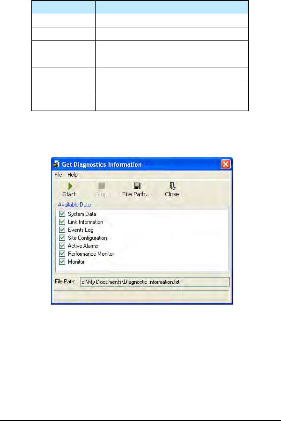
Retrieving Link Information (Get Diagnostics) Chapter 7
RADWIN 1000/2000/5000 User ManualVersion 2.5.30p3 7-2
The following table lists link and system information that can be monitored.
To get diagnostics
1. On the Help menu, choose Get Diagnostic Information.
Figure 7-1: Get Diagnostics Dialog Box
2. Select or deselect the data options. If the file is to be sent to RADWIN
Customer Support leave all options checked.
3. Click File Path to specify the folder in which you want to save the file
and then click Start to save the information.
The file is saved in the specified folder as Diagnostics Informa-
tion.txt
Table 7-1: Get Diagnostics Data and Description
Data Description
System Data General information about the system
Link Information Information about the link properties
Events Log List of recent system events
Site Configuration Data about the site parameters
Active Alarms List of active alarms
Performance Monitor Network performance data over defined time periods
Monitor Detailed event data record

Link Compatibility Chapter 7
RADWIN 1000/2000/5000 User ManualVersion 2.5.30p3 7-3
Link Compatibility
Link Compatibility indicates the version compatibility using software traps.
As new hardware or software is added to existing networks compatibility
issues may arise. An incompatibility issue is indicated to the user by a
change of color of the Link Status box on the Main Menu screen. Trap mes-
sages in the events Log indicate the problems or limitations and suggest
upgrades when appropriate.
The following Link Status messages are given:
fullCompatibility - different software versions were detected that are fully
compatible. The message indicates that an upgrade is available.
restrictedCompatibility - different software versions were detected that
operate correctly. However, new features are not supported
softwareUpgradeRequired - different software versions were detected allow-
ing limited operation. The message is, that a software upgrade required.
versionsIncompatibility - different software versions were detected that are
incompatible. You need to perform local upgrades.
Reinstalling and Realigning a Link
It may be necessary to reinstall the link if the ODUs need to be realigned.
Table 7-2: Link Compatibility Trap Messages
Link State Link State
text
Link
Status
Color
Site
Description
Site
Desc.
Color
Link Status
Color
fullCompatibility Active Green SW Upgrade
Available Yellow Green
restrictedCompatibility Active - SW
Version
mismatch
Magenta
(Same as
authen-
tication
error)
SW Upgrade
Recommended Yellow Magenta
(Same as
authentication
error)
softwareUpgradeRequired Active – SW
Upgrade
Required
Brown
(Major) SW Upgrade
Required Yellow Brown (Major)
versionsIncompatibility Not Active -
SW
Upgrade
Required
Red Local SW
Upgrade
Required
Yellow Red
Note
Activating Install Mode causes both sites to go into install mode, causing
disruption in service for approximately fifteen seconds.

The Link Budget Calculator Chapter 7
RADWIN 1000/2000/5000 User ManualVersion 2.5.30p3 7-4
To reinstall the link:
1. Choose a site.
The Configuration dialog box opens.
2. In the Configuration dialog box, click the Install Mode button.
A message box asking if you want to enter install mode appears.
3. Click Yes to continue.
The system enters Install mode and the alignment tone becomes audi-
ble.
4. Realign the ODUs and start the Installation wizard (see chapter 4).
The Link Budget Calculator
The Link Budget Calculator is part of the RADWIN Manager software and is
found in the Help menu. This useful utility enables you to calculate the
expected performance of the wireless link and the possible configurations
for a specific link range including antenna size, cable loss and climate condi-
tions. For full details, see appendix D.
Performance Monitoring
RADWIN 1000/2000/5000 Performance Monitoring constantly monitors traf-
fic over the radio link and collects statistics data for the air interface and
Ethernet ports. It does so continuously, even when the RADWIN Manager is
not connected.
Two types of logs are recorded:
•Monitor Log that records statistics on traffic rate and radio signal
strength.
•Events Log that records when the rates fall above or below a pre-
defined threshold.
Both the statistics Monitor log and events log can be saved as TXT files.
The Monitor Log
The Monitor Log records performance statistics for predefined intervals. You
can save the monitor log to a text file, as well as display the information in
an on-screen report.
Saving the Monitor Log
You can save the recorded Monitor Log statistics to a text file.
To save the monitor log:
1. From the Tools menu, choose Preferences.
The Preferences dialog box appears:
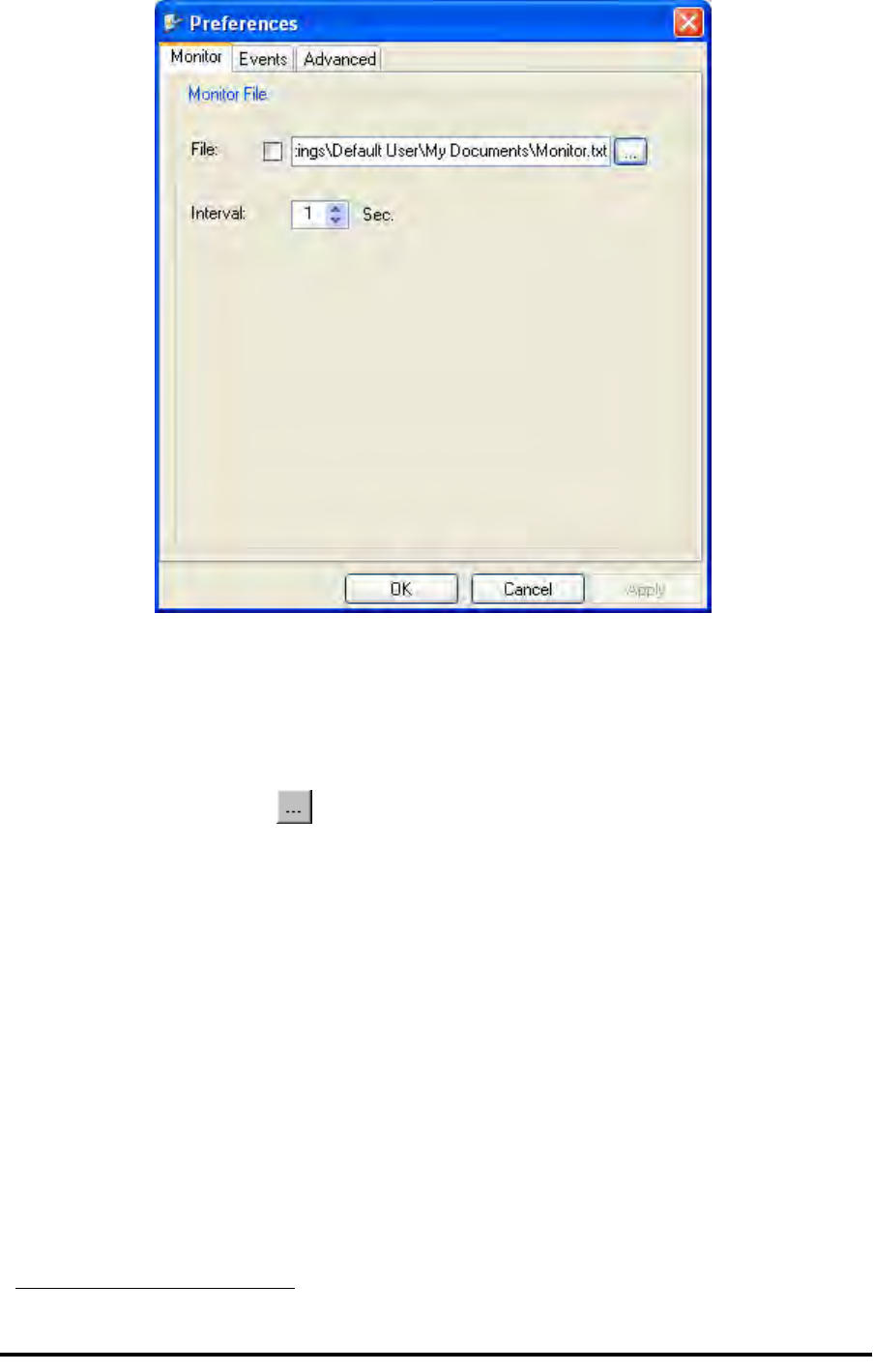
The Monitor Log Chapter 7
RADWIN 1000/2000/5000 User ManualVersion 2.5.30p3 7-5
Figure 7-2: Preferences dialog box
2. Click the Monitor Tab.
3. Select the file to save.
4. Click the check box to open the file for saving.
5. Click the button and in the Select File dialog box indicate in which
folder and under what name the monitor log file is to be saved.
6. Set the time interval for adding data to the file.
7. Click OK to save the file.
Viewing Performance Reports
The Performance Monitor Report displays performance views of each of the
interfaces1.
To obtain performance monitoring reports:
1. From the main menu, choose Tools | Performance Monitoring
Report ...
You are presented with the following window:
1. Ethernet performance is not collected from PoE devices.
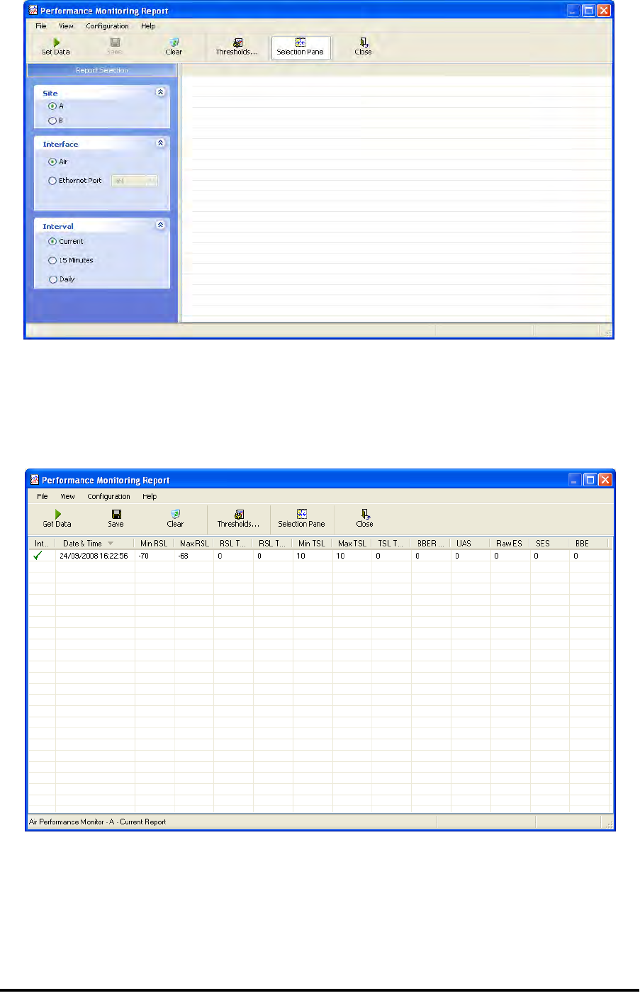
The Monitor Log Chapter 7
RADWIN 1000/2000/5000 User ManualVersion 2.5.30p3 7-6
Figure 7-3: Basic Performance Monitoring Report
2. Choose a report type from the left panel and click the Get Data toolbar
button. For example, if you choose Site A, Air and Current, you will be
offered a report looking like this:
Figure 7-4: A typical Performance Monitoring Report
You can click the Selection Pane icon to toggle the side panel on or off.
The other reports look similar. Here is a detailed description of the reports
and their fields:

The Monitor Log Chapter 7
RADWIN 1000/2000/5000 User ManualVersion 2.5.30p3 7-7
Several performance data occurrences are collected for each of the inter-
faces (ES, SES, and UAS), as well as Specific data per Interface type (e.g.,
TX and RX bytes for Ethernet). For the Air Interface, user defined thresholds
data are collected. Refer to table 7-3 and table 7-4, in Performance
Monitoring Report Toolbar below.
Data is collected and selectively displayed based on three time intervals as
selected by the Interval radio buttons:
• Current (t=0)
• 15 minutes Intervals
• Daily

The Monitor Log Chapter 7
RADWIN 1000/2000/5000 User ManualVersion 2.5.30p3 7-8
Table 7-3: Explanation of performance data
Data type Reported Value Explanation
Generic PM Data
UAS – Unavailable
Seconds Seconds in which the interface was out of service.
ES – Errored Sec-
onds The number of seconds in which there was at least
one error block. Note that the notation of an error
block is different per interface.
SES – Severe Errored
Seconds The number of seconds in which the service quality
was low (the quality is different per type of inter-
face and determined by the BBER threshold per
interface).
BBE – Background
Block Error The number of errored blocks in an interval.
Integrity A flag indicating that the data was valid. Note that
the Performance Monitoring data is not valid if not
all the values were stored (e.g., due to clock
changes within the interval or power up reset).
Air Interface PM
Data
Max RSL The maximum of the receive signal level (mea-
sured in dBm).
Min RSL The minimum of the receive signal level (measured
in dBm).
Max TSL The maximum of the transmit signal level (mea-
sured in dBm).
Min TSL The minimum of the transmit signal level (mea-
sured in dBm).
RSL Threshold 1 The number of seconds in which the RSL was
below the specified threshold.
RSL Threshold 2 The number of seconds in which the RSL was
below the specified threshold.
TSL Threshold The number of seconds in which the RSL was
above the specified threshold.
BBER Threshold The BBER Threshold value counts the number of
seconds in which the Background Block Error Ratio
(BBER) exceeded the specified threshold.
Ethernet Interface
PM Data
Received Bytes The number of Megabytes received at the specified
port within the interval
Transmitted Bytes The number of Megabytes transmitted at the spec-
ified port within the interval.
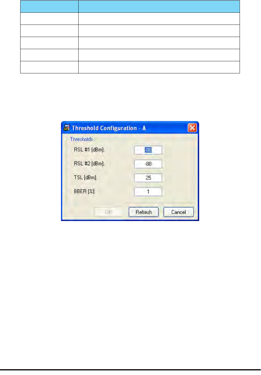
The Monitor Log Chapter 7
RADWIN 1000/2000/5000 User ManualVersion 2.5.30p3 7-9
Performance Monitoring Report Toolbar
You can use the toolbar to perform the actions described in the following
table:
Setting Air Interface Thresholds
Use the Thresholds button on the Monitoring Performance Report toolbar to
set the Air Interface Thresholds:
Figure 7-5: Threshold configuration dialog box
BBER Threshold
This parameter counts the seconds during which the radio performance is
below a user specified threshold. The threshold is measured as a percent-
age. The threshold can be set from 0.1% up to 50%.
For links with Ethernet only service, 8% threshold is recommended. If there
are no problems during the interval, then for that threshold, the recom-
mended BBER value should be 0. Since the system provides a lossless
Ethernet service, there is throughput degradation in case of interference.
The degradation is proportional to the BBER.
RSL Threshold
RSL Threshold can also be used as an indicator of problems in the radio
channel. You can check the RSS by from the Link Budget Calculator results
Table 7-4: Action of the toolbar buttons
Command Button Action
Get Data Gathers current performance monitoring data.
Save Save current performance monitoring data to a file
Clear Clear current performance monitoring data.
Thresholds Set Air Interface Thresholds
Close Closes the active alarm window.
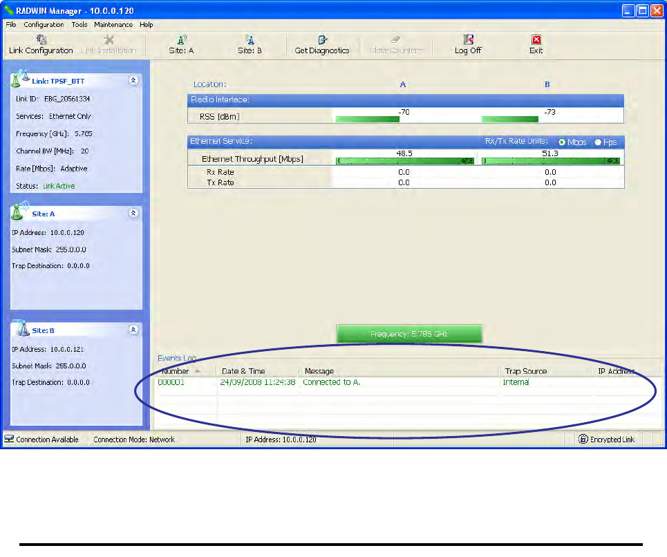
The Events Log Chapter 7
RADWIN 1000/2000/5000 User ManualVersion 2.5.30p3 7-10
during installation. A value of -5dB from the current RSS is recommended as
a threshold.
The Events Log
The Events Log records system failures, loss of synchronization, loss of sig-
nal, compatibility problems and other fault conditions and events.
Alarms (traps) are displayed in the Events Log in the lower panel of the
main window. The Events Log may be saved as a text file.
The Events Log includes the following fields:
Sequential number (ID)
Date and time stamp
Message
Trap source
IP address of the ODU that initiated alarm.
For complete information about traps and alarms see appendix F, MIB Ref-
erence, table F-3.
The events are displayed in the Events Log in the lower part of the RADWIN
Manager main window:
Figure 7-6: Events Log Display

RADWIN Manager Traps Chapter 7
RADWIN 1000/2000/5000 User ManualVersion 2.5.30p3 7-11
RADWIN Manager Traps
The RADWIN Manager application issues traps to indicate various events,
displayed in the Wvents Log.
Table 7-5: RADWIN Manager Trap Messages
Trap Message Severity Remarks
Error loading trap catcher. Port 162 is already in use. Warning NMS will not catch any
traps from target, some
other application has
grabbed this port
Device unreachable! Error Check connectivity to target
Connected to <site_name> Information
<site_name> Site will be reset. Information
Restore Factory Default Settings in process on Site
<site_name> Information
Factory Settings: The process was not finished due to
connection issues. Warning Factory setting failed due to
connectivity problem to tar-
get
Reset: The process was not finished due to connec-
tion issues. Warning Factory setting failed due to
connectivity problem to tar-
get - Target will not be
reset
Cannot Write to Monitor file. There is not enough
space on the disk. Warning Free some space on disk
and retry
Windows Error: <error_ID>. Cannot Write to Monitor
file. Warning Operating System error
TDM Counters were cleared for both sides Information
Identical IP addresses at <local_site_name> and
<remote_site_name> Warning Set up a different IP to each
site
The Product is not identified at the
<local_site_name> site. Warning NMS is incompatible with
the target release
The Product is not identified at the
<remote_site_name> site. Warning
The Product is not identified at both sites. Warning
Product Not Identified! Warning
The Manager identified a newer ODU release at the
<remote_site_name> site. Warning ODU release is newer than
NMS release. Wizards are
not available. NMS will be
used just for monitoring.
Upgrade the NMS. (You will
get this message as a pop
up)

RADWIN Manager Traps Chapter 7
RADWIN 1000/2000/5000 User ManualVersion 2.5.30p3 7-12
Setting the Events Preferences
You can define a color for the traps to be displayed in the Event Log win-
dow, according to the severity of the event. The severity is predefined.
To set the trap color:
1. From the Tools menu, choose Preferences.
The Preferences dialog box appears.
2. Click the Events Tab:
The Manager identified a newer ODU release at both
sites. Warning
The Manager identified a newer ODU release at the
<local_site_name> site. Warning
Newer Version identified at the <local_site_name>
site. Warning ODU release is newer than
NMS release. Wizards are
not available. NMS will be
used just for monitoring.
Upgrade the NMS
Newer Version identified at the <remote_site_name>
site. Warning
Newer Version Identified! Warning
Table 7-5: RADWIN Manager Trap Messages
Trap Message Severity Remarks
RADWIN Manager Traps Chapter 7
RADWIN 1000/2000/5000 User ManualVersion 2.5.30p3 7-13
Figure 7-7: Preferences dialog box
3. Select the event type and click on the button.
A color chart opens.
4. Select the desired color.
5. Repeat for all of the event types.
To set the trap background color:
• Click Background Color to change the text background.
To reset the event colors:
• Click Reset Settings to return to the default color settings.
Saving the Events Log
You can save recorded events in an Events Log text file. New alarms are
automatically added to the text file, as they enter the Events Log.
To save the Events Log:
1. From the Tools menu, choose Preferences.
The Preferences dialog box appears
2. Click the Events Tab.
3. Select the file to save.
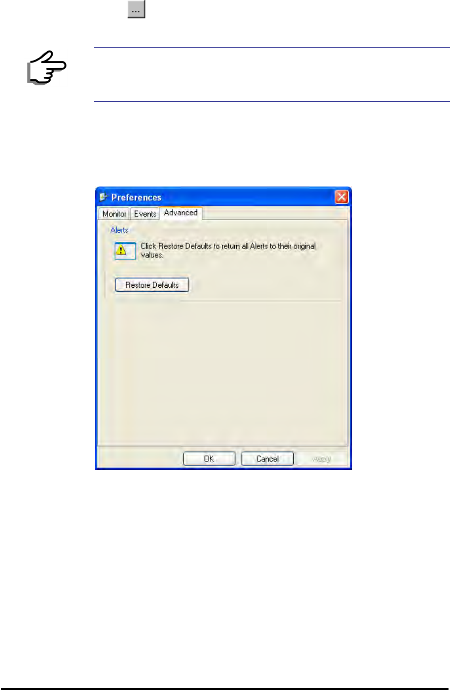
RADWIN Manager Traps Chapter 7
RADWIN 1000/2000/5000 User ManualVersion 2.5.30p3 7-14
4. Click the check box to open the file for saving.
Click the button and in the Select File dialog box indicate in which folder
and under what name the Events Log file is to be saved, and click OK.
Reverting Alarm Messages
Alarm messages can be reverted to their default values by choosing the
Advanced tab from the Preferences dialog:
Just click the Restore Defaults button, followed by OK.
Active Alarms
Upon setting a trap destination, applicable events are reported as active
alarms to the user. The active alarms are saved and can be viewed in the
Active Alarms window.
To view summary of saved alarms:
• From the Tools menu, choose Active Alarm Summary.
The Active Alarms Summary window opens:
Note
To store the Events Log, first define the IP address, subnet mask, default
gateway and trap address of the managing computer (see Configuring
the ODU Address on page 6-4 for details).
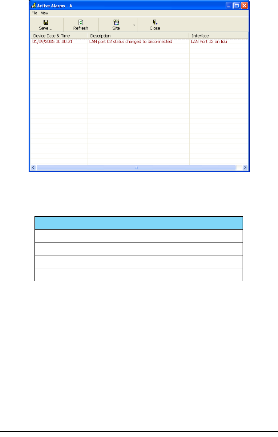
RADWIN Manager Traps Chapter 7
RADWIN 1000/2000/5000 User ManualVersion 2.5.30p3 7-15
Figure 7-8: Active Alarms Summary
The following table provides an explanation of the command buttons
Remote Power Fail Indication
Remote power fail indication indicates to one side that the other side has
had a power failure. The failed site sends a final trap indication about the
power loss just before powering off.
A “Dying-Gasp” circuit identifies the power failure at a minimum interval of
20 milliseconds before the ODU or IDU powers off. During that interval a
message notifying the power failure is sent to Site B. Alarm output number
4 indicates power failure at Site B.
Table 7-6: Active Alarms command buttons
Command Action
Save Saves the alarms in CSV or text format for further analysis.
Refresh Reads the alarms from the ODU.
Site Selects site for the active alarms.
Close Closes the active alarm window.

Troubleshooting Chapter 7
RADWIN 1000/2000/5000 User ManualVersion 2.5.30p3 7-16
Troubleshooting
Use the following table to troubleshoot LED fault indications:
Use the following table to troubleshoot faults in the system:.
Replacing an ODU
Prior to any action ensure that both ODUs have the same software version.
You can see this on the inventory panels for each site.
For Site A, click Site A | Inventory and note the ODU software version.
Repeat this for Site B using Site B | Inventory.
If either ODU has an old software version, perform a software upgrade. It is
important to configure the new ODU exactly the same as the old ODU to
avoid configuration mismatches, which will disrupt the link.
An ODU may be reconfigured in several ways.
• Use the backup Configuration
If a backup of the configuration is available, restore that configura-
tion using Site A| Restore.
Table 7-7: LED fault indicators
LED Status Remedy
PWR Off Check that AC adapter is connected to the IDU-E and the AC
power outlet.
IDU Orange Check that the IDU/ODU cable is properly wired and connected.
ODU Red Check that the IDU/ODU cable is properly wired and connected.
AIR I/F Orange Complete the installation procedure from the management soft-
ware.
Red Check the ODU Antenna alignment. Check that the radio configu-
ration of both site A and site B units are the same (channel and
Link ID).
SVC Off
Table 7-8: Troubleshooting
Symptom Remedy
No power Ensure that power is connected to the IDU.
Ensure that the ODU cable is properly wired and connected.
No signal Complete the installation procedure from the RADWIN Manager
Check the ODU alignment. Check that the radio configuration of both site A
and site B units are the same (channel and Link ID.
Weak signal
received Check the ODU alignment, reconfigure the link.
Check the alignment tone sounds the Best Signal sequence.
Restoring Factory Setup Chapter 7
RADWIN 1000/2000/5000 User ManualVersion 2.5.30p3 7-17
• Manual Configuration
The new ODU can be configured manually according to the link con-
figuration. Remember to use the same settings for Link ID, chan-
nels, link password, IP addresses, and names.
Restoring Factory Setup
To restore factory setup:
1. Set the remaining ODUs back to the factory setup by using the Site A
|Advanced option.
2. Activate the second ODU and carry out a new Installation.
Online Help
Online help can be accessed from the Help menu on the main screen of the
RADWIN 1000/2000/5000 Manager.
Figure 7-9: Online Help for RADWIN 1000/2000/5000
Customer Support
Customer support for this product can be obtained from the local VAR, Inte-
grator or distributor from whom it was purchased.
For further information, please contact the RADWIN 1000/2000/5000 dis-
tributor nearest to you or one of RADWIN's offices worldwide (see RAD-
WIN Worldwide Offices at the beginning of this manual).

RADWIN 1000/2000/5000 User ManualVersion 2.5.30p3 A-1
Appendix A
Technical Specifications
Configuration
Architecture
ODU: Outdoor Unit with Integrated Antenna or Connector-
ized for External Antenna
IDU: Indoor Unit for service interfaces or PoE device for
Ethernet only
IDU to ODU Interface Outdoor CAT-5e cable; Maximum cable length: 100 m

Radio Appendix A
RADWIN 1000/2000/5000 User ManualVersion 2.5.30p3 A-2
Radio
Capacity
Up to 270Mbps at 40MHz channel bandwidth in the 5.3/5.4
IC and 5.8 GHz spectrum bands
Up to 130Mbps at 20MHz channel bandwidth in the 3.5/3.6
GHz spectrum bands
Range Up to 120 km / 75 miles
Frequency Bands
Band
5.725 – 5.850 GHz
5.725 – 5.825 GHz
5.250 – 5.350 GHz (excluding
40 MHz channel bandwidth
and 6dBi antenna assembly
gain)
5.250 – 5.350 GHz (including
40 MHz channel bandwidth
and 6dBi antenna assembly
gain)
5.470 – 5.725 GHz (excluding
40 MHz channel bandwidth
and 6dBi antenna assembly
gain)
5.470 – 5.725 GHz (including
40 MHz channel bandwidth
and 6dBi antenna assembly
gain)
4.940 – 4.990 GHz
2.400 – 2.4835 GHz
3.650 – 3.700 GHz
3.475 – 3.650 GHz
Regulations
FCC / IC
FCC(UNII)/IC
FCC
IC
FCC
IC
FCC / IC
FCC / IC
FCC / IC
IC
Channel Bandwidth 5, 10, and 20 MHz
40 MHz in the 5.3/5.4 IC and 5.8 GHz spectrum bands
Band Max Tx Power Antenna
5.725 – 5.850 GHz
29.95 dBm 28 dBi Dish
29.95 dBm 24 dBi Integral Flat
29.95 dBm 23 dBi External Flat
23 dBm 14 dBi External Flat
20 dBm 16.5 dBi External Flat
28 dBm 8 dBi assembly

Radio Appendix A
RADWIN 1000/2000/5000 User ManualVersion 2.5.30p3 A-3
5.250 – 5.350 GHz
1.9 dBm 28 dBi Dish
6.5 dBm 23.5 dBi Integral Flat
7.5 dBm 22.5 dBi External Flat
23.5dBm 6 dBi assembly
7.4 dBm 14 dBi External Flat
7.4 dBm 15.5 dBi External Flat
23.5 dBm 6 dBi assembly
5.470 – 5.725 GHz
1.6 dBm 28 dBi Dish
6.3 dBm 23.5 dBi Integral Flat
7.3 dBm 22.5 dBi External Flat
23.7 dBm 6 dBi assembly
7.2 dBm 14 dBi External Flat
7.2 dBm 16.5 dBi External Flat
23.7 dBm 6 dBi assembly
5.725 – 5.825 GHz
23.8 dBm 28 dBi Dish
26.4 dBm 22.5 dBi Integral Flat
26.4 dBm 23.5 dBi External Flat
29.4 dBm 6 dBi assembly
24.4 dBm 14 dBi External Flat
24 dBm 16.5 dBi External Flat
29.3 dBm 6 dBi assembly
4.940 – 4.990 GHz
31 dBm 21 dBi Integral Flat
31 dBm 21 dBi External Flat
31 dBm 28 dBi Dish
31 dBm 14 dBi External Flat
31 dBm 15 dBi External Flat
2.400 – 2.4835 GHz
25.5 dBm* 20 dBi External Flat
25.5 dBm* 17.5 dBi Integral Flat
23.7 dBm 20 dBi External Flat
23.7 dBm 17.5 dBi Integral Flat
3.475 – 3.650 GHz
26 dBm 21 dBi Integral Flat
26 dBm 22 dBi External Flat
26 dBm 25 dBi Dish
3.650 – 3.700 GHz 25.6 dBm 13.5 dBi assembly
Band Max Tx Power Antenna

Ethernet Interface Appendix A
RADWIN 1000/2000/5000 User ManualVersion 2.5.30p3 A-4
* Relevant for RADWIN 1000 RW-1020-0150 / RADWIN 2000 RW-2020-
0150 models only
Ethernet Interface
Channel Bandwidth 5, 10, and 20 MHz, (10MHz not supported in the 5.8 GHz
band)
Radio Modulation 2x2 MIMO-OFDM (BPSK/QPSK/16QAM/64QAM)
Adaptive Modulation & Coding Supported
Automatic Channel Selection Supported
Radio Regulation FCC 47 CFR Part 15 Subpart C, E, Part 90 Subpart Y, Z
IC (Canada) RSS-210, RSS-111, RSS-192, RSS-197
Duplex Technology TDD
Error Correction FEC k = 1/2, 2/3, 3/4, 5/6
Rate – Single Antenna [Mbps] 6.5 13 19.5 26 39 52 58.5 65
Rate – Single Antenna in the
5.8 GHz spectrum band
[Mbps] 13.5 27 40.5 54 81 108 121.5 135
Rate – Dual Antenna [Mbps] 13 26 39 52 78 104 117 130
Rate –Dual Antenna in the 5.8
GHz spectrum band [Mbps] 27 54 81 108 162 216 243 270
Modulation BPSK QPSK 16QAM 64QAM
FEC [k=] 1/2 1/2 3/4 1/2 3/4 2/3 3/4 5/6
Max Tx Power [dBm] 25 24 21 19 18
Sensitivity (dBm) @BER <10e-
11 (20MHz) -88 -86 -83 -81 -80 -72 -70 -67
Encryption AES 128
Throughput Up to 270Mbps in the 5.3/5.4 IC and 5.8 GHz spectrum
bands
Number of Ethernet ports IDU-C and E: 2; PoE Device: 1
Type 10/100BaseT with Auto-Negotiation (IEEE 802.3u)
Framing/Coding IEEE 802.3
Line Impedance 100 Ω
VLAN Support Transparent
Connector RJ-45
Maximum Frame Size 2048 Bytes
Bridge Layer 2, self-learning of up to 2047 MAC addresses (IEEE
802.1Q), hub/Bridge selectable mode
Latency 3 msec (typical)

Management Appendix A
RADWIN 1000/2000/5000 User ManualVersion 2.5.30p3 A-5
Management
Mechanical
Power
Environmental
Safety
EMC
Air Interface
Management Application RADWIN Manager
Protocol SNMP and Telnet
Dimensions
ODU with Integrated Antenna: 37.1/14.84(W) x 37.1/
14.84(H) x 9.00/3.6(D) cm/in; 3.5 kg / 7 lbs
ODU Connectorized: 18.0/7.2(W) x 27.0/10.8(H) x 5.5/
2.2(D) cm/in; 1.5 kg / 3.0 lbs
IDU-C: 43.6/17.2(W) x 4.5/1.7(H) x 21/8.3(D) cm; 1.5 kg /
3.3 lbs
IDU-E: 22/8.7(W) x 4.4/1.7(H) x 17/6.7(D) cm/in; 0.5 Kg /
1.1 lbs
Power Feeding Dual feeding, -20 to -60 VDC (AC/DC converter is available)
Power Consumption < 35 W (IDU+ODU)
Operating Temperatures ODU: -35°C to +60°C / -31°F to +140°F
IDU-C: 0°C to +50°C / 32°F to +122°F
IDU-E: -5°C to 45°C / 32°F to 122°F
Humidity ODU: Up to 100% non-condensing, IP67
IDU: 90% non-condensing
FCC/IC (cTUVus) UL 60950-1, CAN/CSA 60950-1 C22.2
ETSI EN/IEC 60950-1
FCC CFR47 Class B, Part15, Subpart B
ETSI EN 300 386 (2005), EN 301 489-1 (2001), EN 301 489-4
(2002)
CAN/CSA-CEI/IEC CISPR 22-02
AS/NZS CISPR 22:2002

Air Interface Appendix A
RADWIN 1000/2000/5000 User ManualVersion 2.5.30p3 A-6
RADWIN 1000/2000/5000 is available in several different frequency band
ranges that comply with ETSI, FCC and IC regulations.
The RADWIN 1000 RW-1020-0150 / RADWIN 2000 RW-2020-0150 is avail-
able only in the 2.4GHz frequency band range that complies with FCC and
IC regulations.
The RADWIN 1000 3GHz Band / RADWIN 2000 3GHz Band / RADWIN 5000
3GHz Band support the 3.5 / 3.6 GHz frequency bands and comply with FCC
and IC regulations.

RADWIN 1000/2000/5000 User ManualVersion 2.5.30p3 B-1
Appendix B
Wiring Specifications
ODU-IDU Cable
The ODU-IDU cable is shielded/outdoor class CAT-5e, 4 twisted-pair 24
AWG terminated with RJ-45 connectors on both ends. A cable gland on the
ODU side provides hermetic sealing.
The following table shows the connector pinout:
User Port Connectors
LAN Port
The LAN 10/100BaseT interface terminates in an 8-pin RJ-45 connector,
wired in accordance to table B-2.
Table B-1: ODU-IDU Connector Pinout
Function Color IDU RJ-45 ODU
RJ-45
Ethernet (RxN) White/Green 1 twisted
2 pair 1
Ethernet (RxT) Green 2
Ethernet (TxT) White/Orange 3 twisted
6 pair 3
Ethernet (TxN) Orange 6
Power (+) Blue 4 twisted
5 pair 4
Power (+) White/Blue 5
Power () White/Brown 7 twisted
8 pair 7
Power () Brown 8

LAN Port Appendix B
RADWIN 1000/2000/5000 User ManualVersion 2.5.30p3 B-2
Table B-2: Fast Ethernet Connector Pinout
Pin Signal Function
1 TD (+) Transmit Data
(positive)
2 TD (–) Transmit Data
(negative)
3 RD (+) Receive Data
(positive)
6 RD (–) Receive Data
(negative)

IDU-C Alarm Connector Appendix B
RADWIN 1000/2000/5000 User ManualVersion 2.5.30p3 B-3
IDU-C Alarm Connector
The IDU-C Alarm interface is a 25 pin D type female connector. Its pinout is
listed in table B-3.
The following diagram describes how to connect external input and output
alarms.
Table B-3: IDU-C Alarm Connector (Dry-Contact)
I/O Description Pin
Input 1 Positive 14
Input 1 Negative 15
Input 2 Positive 16
Input 2 Negative 17
Input 3 Positive 18
Input 3 Negative 19
Input 4 Positive 20
Input 4 Negative 21
Output 1 Normally Open 1
Output 1 Common 2
Output 1 Normally
Closed 3
Output 2 Normally Open 4
Output 2 Common 5
Output 2 Normally
Closed 6
Output 3 Normally Open 7
Output 3 Common 8
Output 3 Normally
Closed 9
Output 4 Normally Open 10
Output 4 Common 11
Output 4 Normally
Closed 12
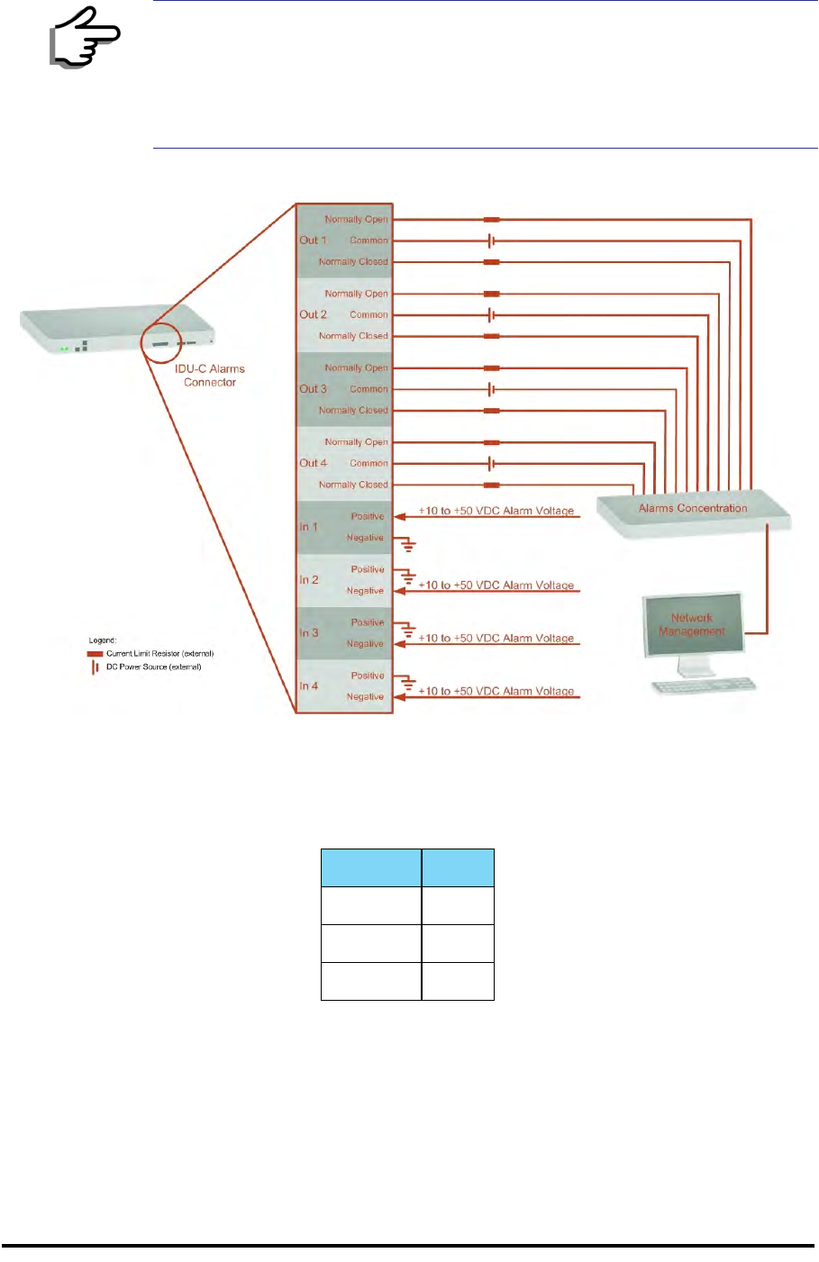
IDU-C Alarm Connector Appendix B
RADWIN 1000/2000/5000 User ManualVersion 2.5.30p3 B-4
Figure B-1: Example for connecting the alarm connector
DC Power Terminal
Note
• Use an external current limit resistor to limit the current at the output
relays to 1 Ampere. Such resistor is not required if the equipment
connected to the IDU supports current limiting to 1 Amp.
• The voltage of the input alarm must be within the range of -10 to -50
VDC.
Table B-4: Terminal Block 3-pin -48VDC
Function Pin
+ Right
Chassis Center
– Left
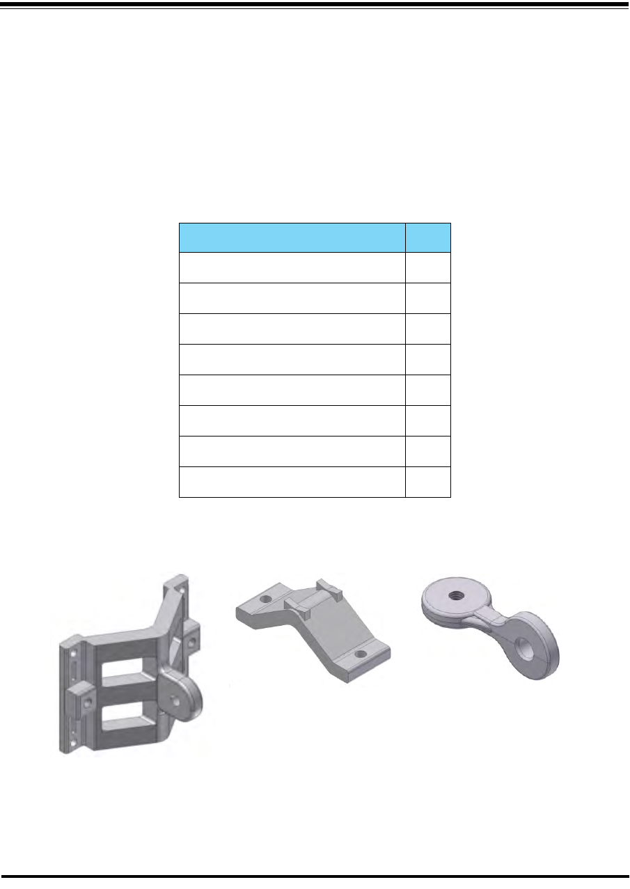
RADWIN 1000/2000/5000 User ManualVersion 2.5.30p3 C-1
Appendix C
Pole and Wall Installation
ODU Mounting Kit Contents
Table C-1: Bill of Materials: ODU mounting kit
Item Qty
Large Clamp (see figure C-1)1
Small Clamp (see figure C-2)1
Arm (see figure C-3)1
Screw hex head M8x40 4
Screw hex head M8x70 2
Washer flat M8 4
Washer spring M8 3
M8 Nuts 2
Figure C-1: Large Clamp Figure C-2: Small Clamp Figure C-3: Arm
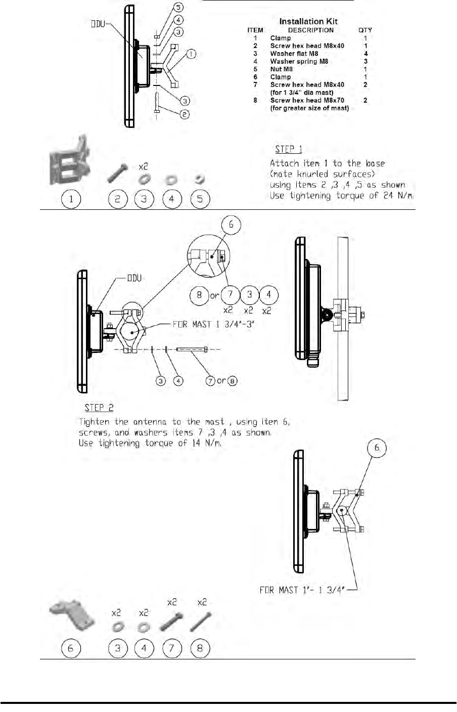
Mounting RADWIN 1000/2000/5000 on a pole Appendix C
RADWIN 1000/2000/5000 User ManualVersion 2.5.30p3 C-2
Mounting RADWIN 1000/2000/5000 on a pole
Figure C-4: Mounting on a pole
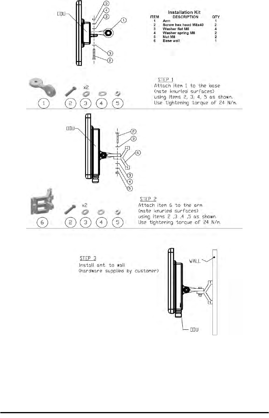
Mounting RADWIN 1000/2000/5000 on a Wall Appendix C
RADWIN 1000/2000/5000 User ManualVersion 2.5.30p3 C-3
Mounting RADWIN 1000/2000/5000 on a Wall
Figure C-5: Mounting on a Wall
Mounting an External Antenna
Optional external antennas can be mounted on a pole. The external mount-
ing kit varies according to the specific antenna.

RADWIN 1000/2000/5000 User ManualVersion 2.5.30p3 D-1
Appendix D
Link Budget Calculator
Overview
The Link Budget Calculator is a utility for calculating the expected perfor-
mance of the RADWIN 1000/2000/5000 wireless link and the possible con-
figurations for a specific link range.
The utility allows you to calculate the expected RSS of the link, and find the
type of services and their effective throughput as a function of the link
range and deployment conditions.
User Input
You are required to enter or choose the following parameters. Depending
on the product, some of the parameters have a default value that cannot be
changed.
• Product (or Regulation and Band)
• Channel Bandwidth (fixed to 20 MHz for RADWIN 1000/2000/5000)
• Tx Power (maximum Tx power per modulation is validated)
• Antenna Type (cannot be changed for ODU with integrated antenna)
• Antenna Gain per site (cannot be changed for integrated antenna)
• Cable Loss per site (cannot be changed for integrated antenna)
• Required Fade Margin
• Rate (and Adaptive check box)
• Service Type (Ethernet Only for RADWIN 1000/2000/5000 version
2.1)
• Required Range
Link Budget Calculator Internal Data
For each product (or Regulation and Band) the calculator stores the follow-
ing data required for link budget calculations:
• Maximum Transmit power (per modulation)
• Receiver Sensitivity (per modulation) for Ethernet service and for
TDM services at various BER

Calculations Appendix D
RADWIN 1000/2000/5000 User ManualVersion 2.5.30p3 D-2
• Maximum linear input power (used to calculate minimum distance)
• Antenna gain and cable loss for ODU with integrated antenna
• Available Channel Bandwidths
Calculations
EIRP
Expected RSS and Fade Margin
where:
Site A is the transmitting site
Site B is the receiving site
PathLoss is calculated according to the free space model,
where Sensitivity is dependent on air-rate.
Min and Max Range
MinRange is the shortest range for which
per air-rate.
MaxRange (with Adaptive checked) is the largest range for which
, at the highest air-rate for which this relation-
ship is true. In a link with adaptive rate this will be the actual behavior.
MaxRange (for a given air-rate) is the largest range for which
.
Service
The Ethernet throughput is calculated according to internal product algo-
rithms.
Availability
The Service Availability calculation is based on the Vigants Barnett method
which predicts the downtime probability based on a climate factor (C fac-
tor).
EIRP TxPower AntennaGainSiteA CableLossSiteA
–+=
E
xpectedRSS EIRP PathLoss AntennaGainSiteB CableLossSiteB
–+–=
P
athLoss 32.45 20 frequencyMHz
20 RequiredRangeKm
10
log+
10
log+=
E
xpectedFadeM inarg Sensitivity ExpectedRSS–=
ExpectedRSS MaxInputPower
ExpectedRSS Sensitivity
E
xpectedRSS Sensitivity RequiredFadeM inarg+

Antenna Height Appendix D
RADWIN 1000/2000/5000 User ManualVersion 2.5.30p3 D-3
Antenna Height
The recommended antenna height required for line of sight is calculated as
the sum the Fresnel zone height and the boresight height. See About the
Fresnel Zone below.
The Fresnel zone height is calculated as:
The boresight clearance height is calculated as:
where .
Running the Link Budget Calculator
The Link Budget Calculator is supplied on the RADWIN Manager CD. It may
be run stand-alone from the CD or from the RADWIN Manager application.
To run the Link Budget Calculator from the CD:
1. Insert the RADWIN Manager CD into the drive on the managing com-
puter. In the window which opens, click the Link Budget Calculator
option.
2. If the CD autorun application does not start by itself, then point your
browser to
Z:\RADWIN\Setup\DATA\Link Budget Calculator.htm
where Z should be replaced with your own CD drive name.
To run the Link Budget Calculator from the RADWIN Manager:
• Choose Help | Link Budget Calculator from the main menu of the
RADWIN Manager as in the following figure:
Availability 610
7–
CfactorfrequencyGHz
RequiredRangeKM
3
10
ExpectedFadeM inarg– 10
-------------------------------------------------------------
=
0.6
300
frequencyGHz
------------------------------------ ExpectedRange
2
----------------------------------------- 2
ExpectedRange
2
----------------------------------------- ExpectedRange
2
-----------------------------------------+
---------------------------------------------------------------------------------------------
R2Maean ExpectedRange
2
----------------------------------------- 2
+RMaean
–
RMean 6367.4425Km=
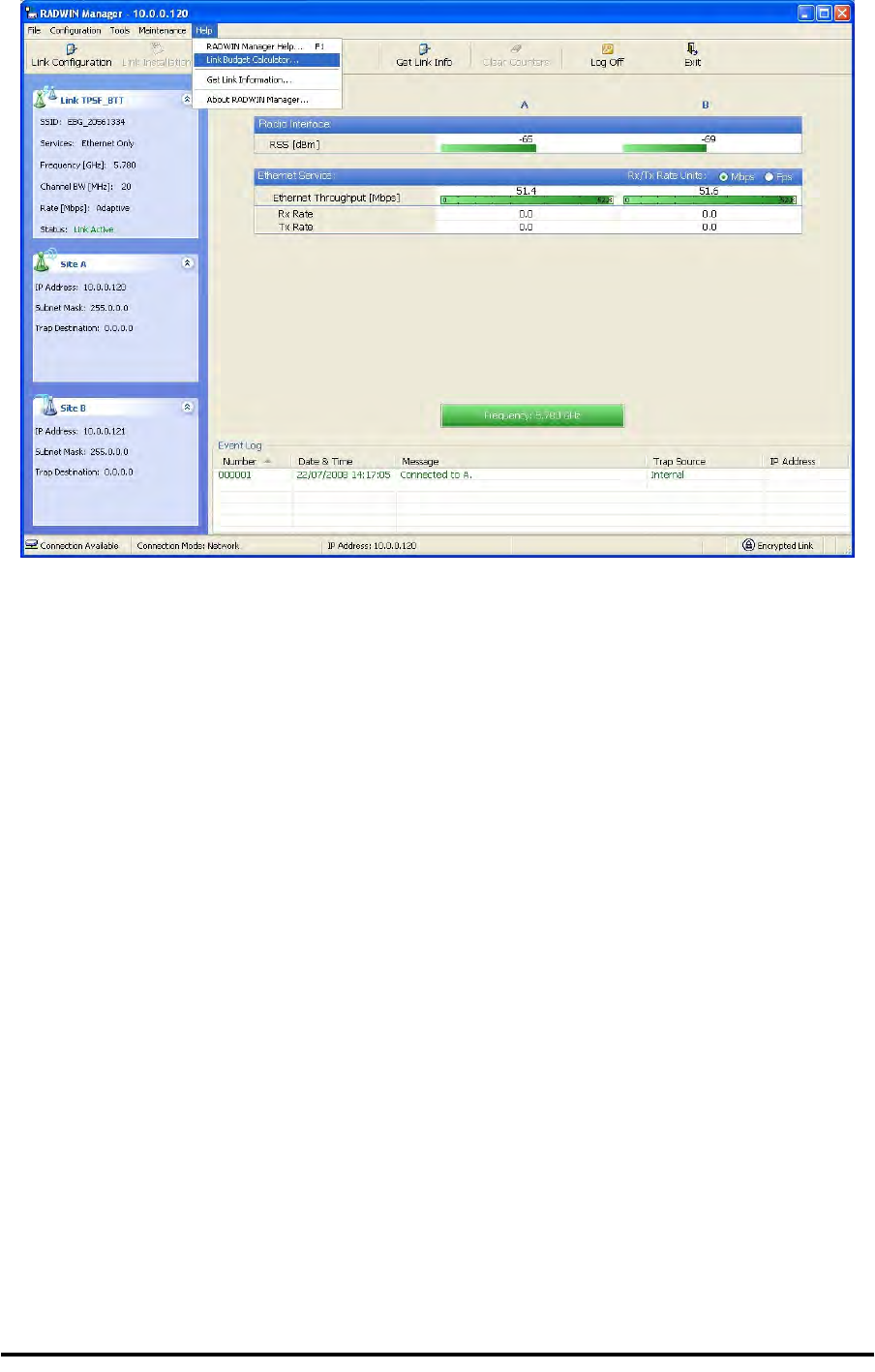
Running the Link Budget Calculator Appendix D
RADWIN 1000/2000/5000 User ManualVersion 2.5.30p3 D-4
Figure D-1: Accessing the Link Budget Calculator
However invoked, your browser displays the following page:
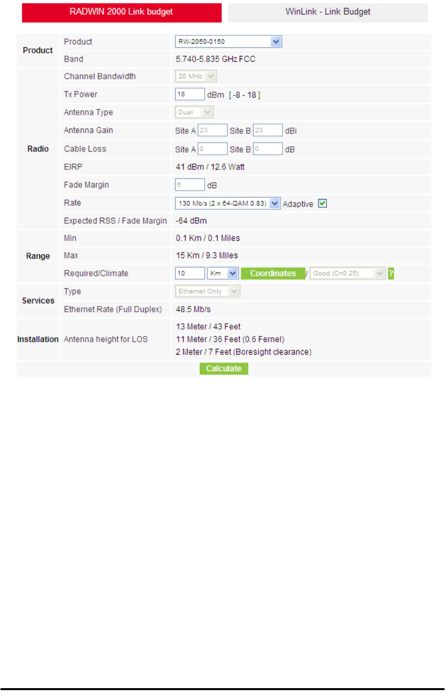
Running the Link Budget Calculator Appendix D
RADWIN 1000/2000/5000 User ManualVersion 2.5.30p3 D-5
Figure D-2: Link Budget Screen
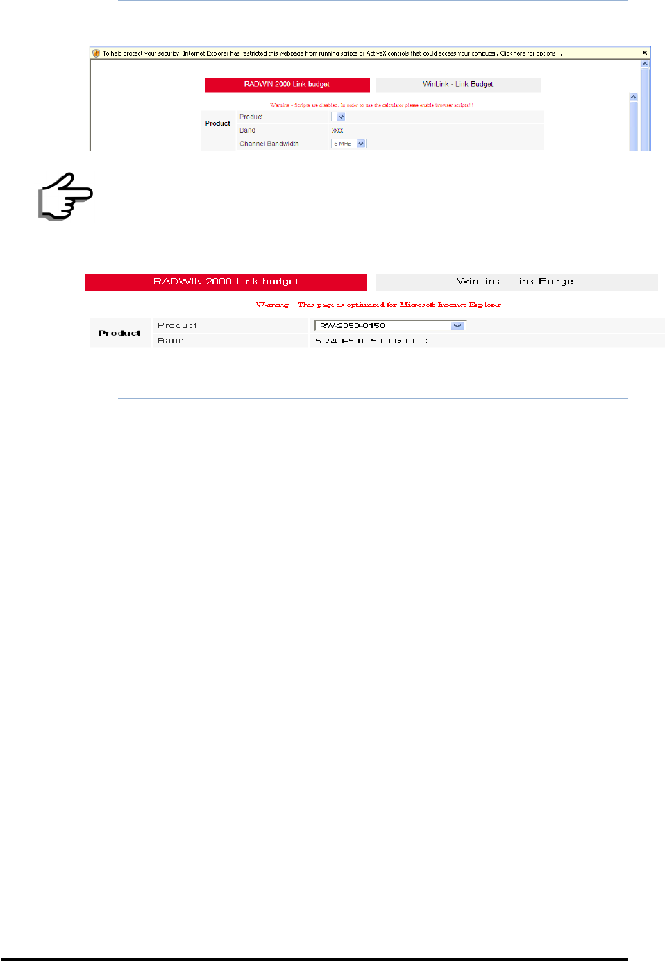
Running the Link Budget Calculator Appendix D
RADWIN 1000/2000/5000 User ManualVersion 2.5.30p3 D-6
To use the Link Budget Calculator for RADWIN 1000/2000/5000:
1. Choose a product from the drop-down list (or choose a Regulation and
Band):
Note
• Microsoft Internet Explorer users may see a warning message like
this:
Click the yellow bar and follow the instructions to allow blocked
content.
• Mozilla FireFox and Google Chrome users may see a warning mes-
sage like this:
You may ignore it and continue.
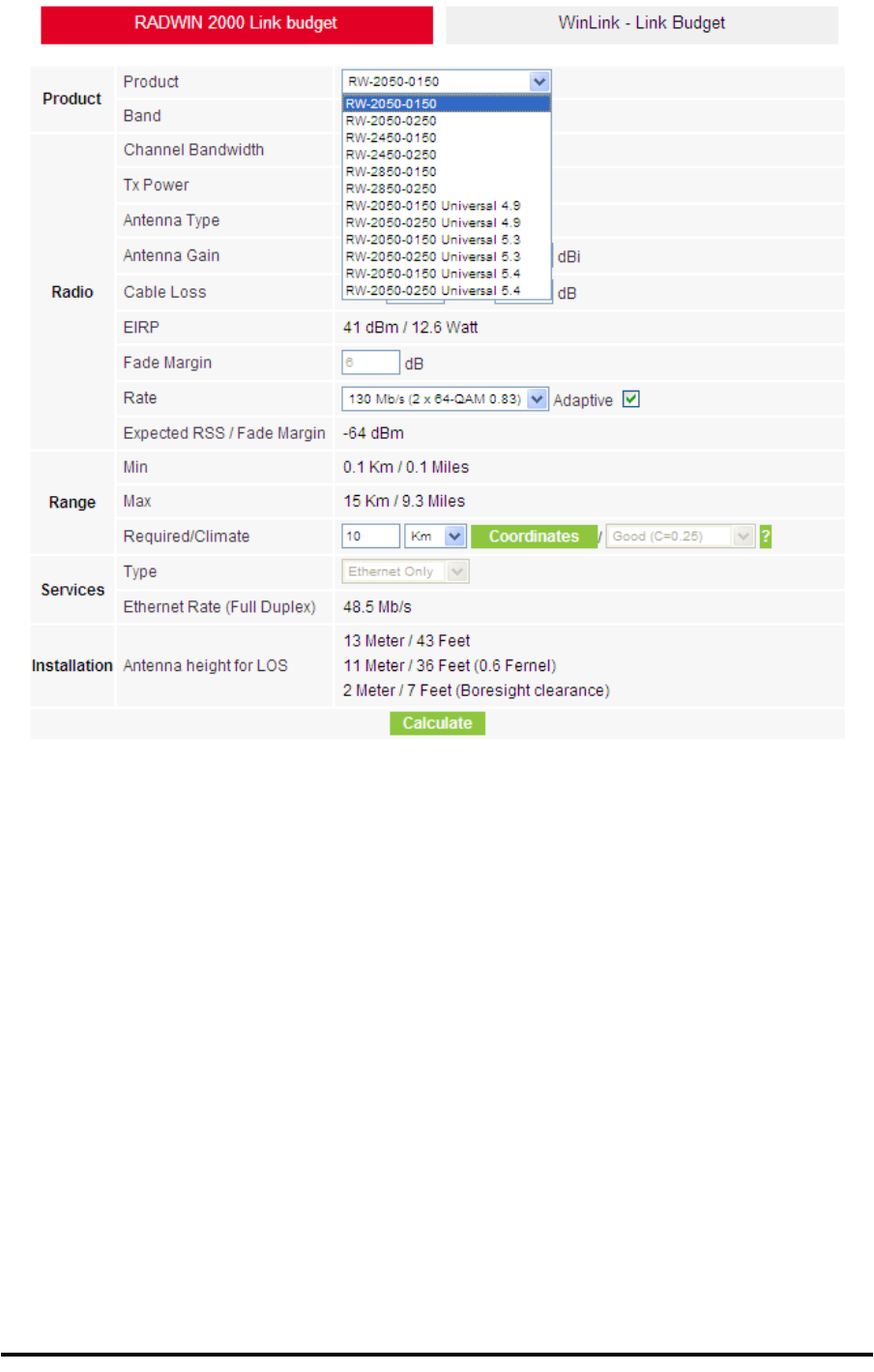
Running the Link Budget Calculator Appendix D
RADWIN 1000/2000/5000 User ManualVersion 2.5.30p3 D-7
Figure D-3: Product selector
2. Enter the radio details. Note that Rate is chosen from a drop-down list:
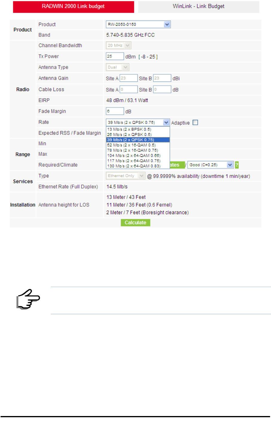
Running the Link Budget Calculator Appendix D
RADWIN 1000/2000/5000 User ManualVersion 2.5.30p3 D-8
Figure D-4: Rate selector
The Rate shown, defines the air-interface rate in Mbps. The system
operates in TDD mode and has the overhead of the air-interface pro-
toco.l Thus, the Ethernet actual throughput is provided by the Ethernet
Rate.
The Fade margin is the minimum required for LOS conditions. For
degraded link conditions, a larger Fade margin should be used.
The EIRP is given in dBm and Watts.
3. If the required range between the two link sites is known, you may enter
it directly. Alternatively, you may enter the latitude and longitude of each
site in the link, in which case the distance between them will be calcu-
lated and displayed.
Note
For a given air-rate, Ethernet throughput will decrease with increasing range
due to propagation delay.
Running the Link Budget Calculator Appendix D
RADWIN 1000/2000/5000 User ManualVersion 2.5.30p3 D-9
Figure D-5: Calculation of distance from site coordinates
Running the Link Budget Calculator Appendix D
RADWIN 1000/2000/5000 User ManualVersion 2.5.30p3 D-10
4. Located to the right of the green Coordinates button is a dropdown list of
Climactic C Factor values.
Figure D-6: Climactic C Factors
For help about what these mean, click the ? button to the right of the list
in figure D-6.

Running the Link Budget Calculator Appendix D
RADWIN 1000/2000/5000 User ManualVersion 2.5.30p3 D-12
Figure D-8: World map showing C Factor contours
5. Click Calculate to obtain the required performance estimate.
The Expected Performance parameters are calculated and displayed:
•Expected RSS - the expected RSS that the RADWIN Manager
shows when the RADWIN 1000/2000/5000 ODUs are optimally
aligned
•Ethernet Rate - maximum throughput available for the chosen
parameter combination
•Antenna height for LOS – the minimum antenna height required
for line-of-sight operation. It is the sum of the height required for
boresight clearance due to the earth’s curvature plus the height
required to clear the Fresnel zone
If the expected performance is not suitable for your application, try different
parameters and repeat the calculation.
Note
Placing the cursor in any other calculated field will also update the
calculated results.
About the Fresnel Zone Appendix D
RADWIN 1000/2000/5000 User ManualVersion 2.5.30p3 D-13
About the Fresnel Zone
The Fresnel zone (pronounced "frA-nel", with a silent “s”) is an elliptically
shaped conical zone of electromagnetic energy that propagates from the
transmitting antenna to the receiving antenna. It is always widest in the
middle of the path between the two antennas.
Figure D-9: Fresnel zone
Fresnel loss is the path loss occurring from multi-path reflections from
reflective surfaces such as water, and intervening obstacles such as build-
ings or mountain peaks within the Fresnel zone.
Radio links should be designed to accommodate obstructions and atmo-
spheric conditions, weather conditions, large bodies of water, and other
reflectors and absorbers of electromagnetic energy.
The Fresnel zone provides us with a way to calculate the amount of clear-
ance that a wireless wave needs from an obstacle to ensure that the obsta-
cle does not attenuate the signal.
There are infinitely many Fresnel zones located coaxially around the center
of the direct wave. The outer boundary of the first Fresnel zone is defined
as the combined path length of all paths, which are half wavelength (1/2 )
of the frequency transmitted longer than the direct path. If the total path
distance is one wavelength (1 ) longer than the direct path, then the outer
boundary is said to be two Fresnel zones. Odd number Fresnel zones rein-
force the direct wave path signal; even number Fresnel zones cancel the
direct wave path signal.

About the Fresnel Zone Appendix D
RADWIN 1000/2000/5000 User ManualVersion 2.5.30p3 D-14
The amount of the Fresnel zone clearance is determined by the wavelength
of the signal, the path length, and the distance to the obstacle. For reliabil-
ity, point-to-point links are designed to have at least 60% of the first Fresnel
zone clear to avoid significant attenuation.
The concept of the Fresnel zone is shown in figure D-9 above. The top of
the obstruction does not extend far into the Fresnel zone, leaving 60% of
the Fresnel zone clear; therefore, the signal is not significantly attenuated.
For more about Fresnel zone, see http://en.wikipedia.org/wiki/
Fresnel_zone.

RADWIN 1000/2000/5000 User ManualVersion 2.5.30p3 E-1
Appendix E
Lightning Protection and
Grounding Guidelines
Meticulous implementation of the guidelines in this appendix will provide
best protection against electric shock and lightning.
The RADWIN 1000/2000/5000™ Lightning protection system consists of the
following components:
• Grounding for the antenna coax cable
• Grounding for each IDU and ODU
• External Primary Surge Suppressor units and grounding for the out-
door cable
• Internal ESD protection circuits over the Power/Telecom lines
Grounding for Antenna Cable
A Grounding Kit must be connected to the coax antenna cable and reliably
grounded as shown in Figure X. The grounding kit is an Andrew Type
223158-2 (www.andrew.com). See figure E-1 below.
Warning
100% protection is neither implied nor possible.
Note
This appendix is at best a guide. The actual degree of lightning protection
required depends on local conditions and regulations.
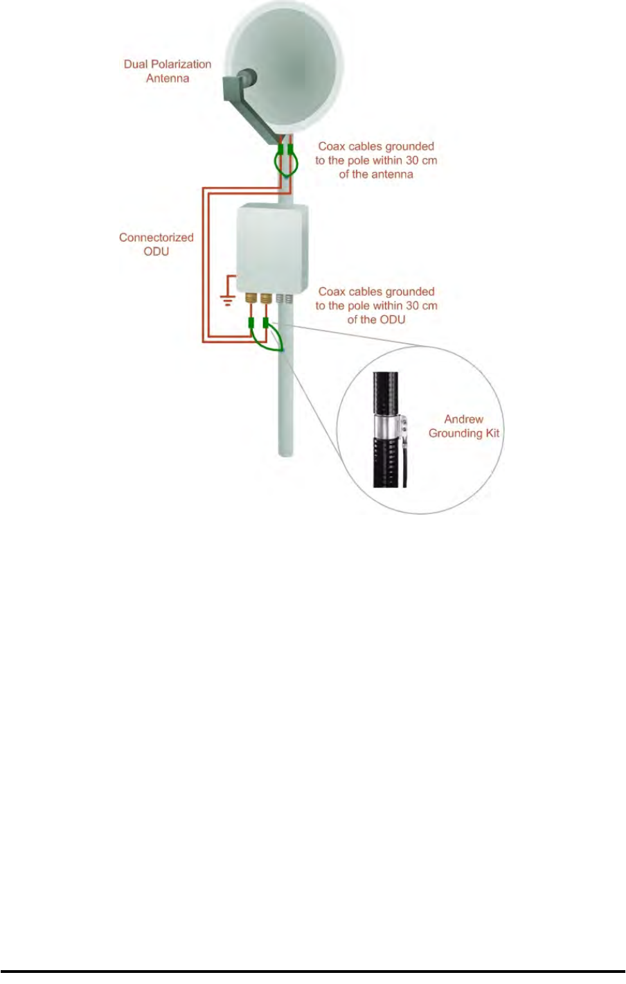
Grounding for Indoor/Outdoor Units Appendix E
RADWIN 1000/2000/5000 User ManualVersion 2.5.30p3 E-2
Figure E-1: Grounding antenna cables
Grounding for Indoor/Outdoor Units
ODU Grounding
RADWIN 1000/2000/5000™ uses a Shielded CAT-5e cable to interconnect
the Outdoor (ODU) and Indoor (IDU) units.
However, this shielding does not provide a good Lightning Discharge path,
since it can not tolerate the high Lightning Current surges.
To provide an alternate Lightning Discharge path, the ODU and antenna
grounding posts should be connected to ground point by a 10 AWG short
copper wire.
The device should be permanently connected to ground.
IDU Grounding
The IDUs grounding post should be connected to the internal ground point,
using a grounding wire of at least 10 AWG. The grounding wire should be
connected to a grounding rod or the building grounding system.
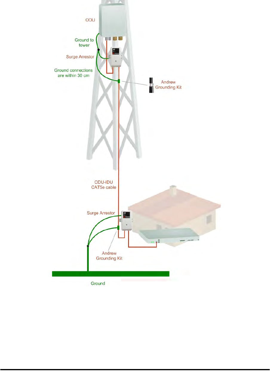
External Lightning Surge Suppressors and Grounding Appendix E
RADWIN 1000/2000/5000 User ManualVersion 2.5.30p3 E-3
The device should be permanently connected to ground.
External Lightning Surge Suppressors and Grounding
A Grounding Kit and Surge Arrestor Unit must be located near the ODU and
properly grounded as illustrated in figure E-2 and figure E-3 below:
Figure E-2: Grounding a typical pole installation
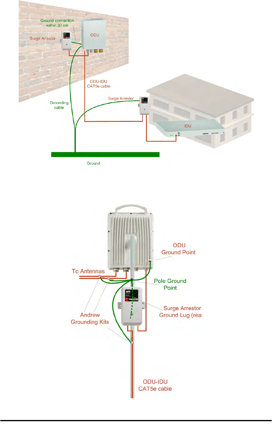
External Lightning Surge Suppressors and Grounding Appendix E
RADWIN 1000/2000/5000 User ManualVersion 2.5.30p3 E-4
Figure E-3: Grounding a typical wall installation
The next figure shows a close-up of the rear of grounded ODU:
Figure E-4: ODU Surge Suppressor and grounding

External Lightning Surge Suppressors and Grounding Appendix E
RADWIN 1000/2000/5000 User ManualVersion 2.5.30p3 E-5
The Transtector protection circuits shown in figure E-5 below, utilize sili-
con avalanche diode technology. The unit consists of an outdoor rated
NEMA 3R type enclosure with easy mounting flanges, ground stud attach-
ment and easy wiring.
The ALPU-POE features RJ-45 protection circuits for the ODU-IDU data pairs
(pins 1,2 & 3,6) and DC power (pins 4,5 & 6,7 with the pairs bonded).
The unit is designed to be wall mounted. An optional set of bracket is avail-
able to allow a wide range of pole mount applications. A dedicated ground
stud is provided inside the unit that must be bonded to the nearest ground-
ing system (or Master Ground bar) for proper surge protection.
The system wiring is installed with RJ-45 type connectors that can feed
directly into the chassis without having to cut, splice or route through awk-
ward strain relief holes.
Figure E-5: Transtector’s Surge Suppressor
To mount the lightning protection devices:
1. Mount the device as close to the ODU as possible. Mount the unit so that
the cable connectors are at the bottom (to prevent water from penetrat-
ing), with the strain reliefs facing the ground.
2. Remove the cover by unscrewing the front of the unit.
3. Mount the unit to an outside surface using the two mounting holes.
4. Connect the ODU-IDU cable using the RJ-45 jack.
5. Connect one cable between the ODU and the suppressor using an RJ-45
jack.
6. Connect the suppressor’s ground stud to a grounding point. Use the
appropriate wire gauge and type, keeping the wire as short as possible,
less than 1m (3’), between the stud and the site grounding point.

External Lightning Surge Suppressors and Grounding Appendix E
RADWIN 1000/2000/5000 User ManualVersion 2.5.30p3 E-6
7. Replace the cover.
A second Surge Arrestor Unit should be mounted at the building entry point
and must be grounded, as shown in figure E-3 above.
To mount the lightning protection at the building entry point:
1. Mount the device outside the building, located as near as possible to the
entrance of the CAT-5e ODU-IDU cable. Mount the unit so that the cable
connectors are at the bottom (to prevent water from penetrating), with
the strain reliefs facing the ground.
2. Remove the cover by unscrewing the front of the unit.
3. Mount the unit to an outside surface using the two mounting holes.
4. Connect the ODU-IDU cable using the RJ-45 jack.
5. Connect one cable between the IDU and the suppressor using an RJ-45
jack.
6. Connect the suppressor’s ground stud to a grounding point. Use the
appropriate wire gauge and type, keeping the wire as short as possible,
less than 1m (3’), between the stud and the site grounding point.
7. Replace the cover
Note
There may also be regulatory requirements to cross bond the ODU-IDU CAT-
5e cable at regular intervals up the mast. This may be as frequent as every
10 meters (33 feet).
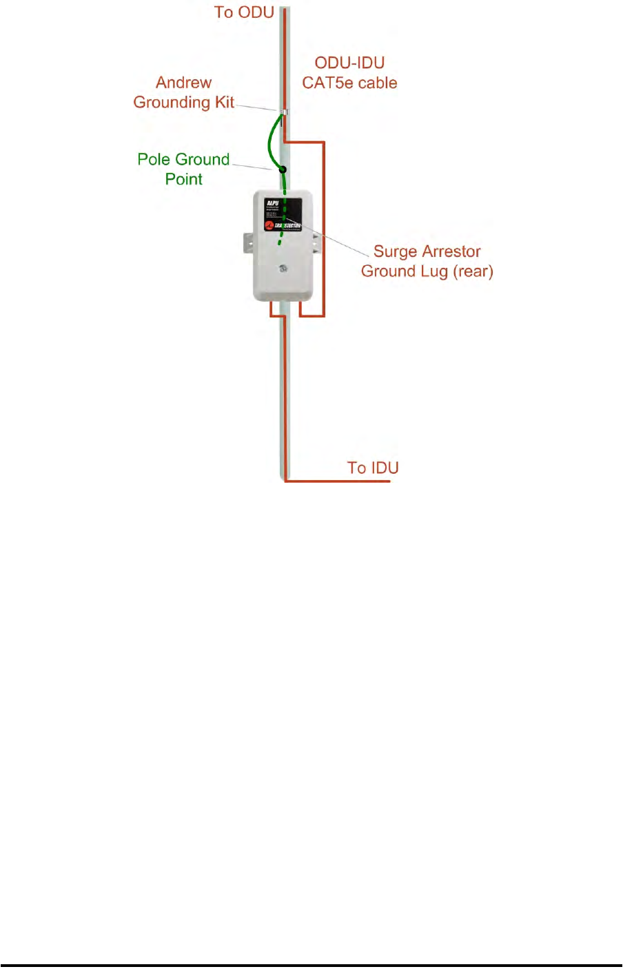
Internal ESD Protection circuits Appendix E
RADWIN 1000/2000/5000 User ManualVersion 2.5.30p3 E-7
Figure E-6: Surge Suppressor and grounding at building entry point
Internal ESD Protection circuits
RADWIN 1000/2000/5000™ is designed to meet the ETSI/FCC/Aus/NZ/CSA
EMC and Safety requirements. To fulfill these requirements, the system's
Telecom lines at the ODU/IDU are Transformer-isolated and include internal
ESD (Electro-Static-Discharge) Protection circuits.

RADWIN 1000/2000/5000 User ManualVersion 2.5.30p3 F-1
Appendix F
MIB Reference
Introduction
About the MIB
The RADWIN MIB is a set of APIs that enables external applications to con-
trol RADWIN equipment.
The MIB is divided into public and a private API groups:
•Public: RFC-1213 (MIB II) variables, RFC-1214 (MIB II) System and
Interfaces sections
•Private: Controlled by RADWIN and supplements the public group.
This appendix describes the public and private MIB used by RADWIN.
Terminology
The following terms are used in this appendix.
In addition, the MIB uses internally, the older notions of Local site and
Remote site where this manual would use site A and site B.
To avoid burdening the reader, this appendix will follow the MIB usage.
Interface API
Control Method
The RADWIN Manager application provides all the means to configure and
monitor a RADWIN 1000/2000/5000 link, communicating with the SNMP
agent in each ODU. Each SNMP agent contains data on each of the IDUs
Term Meaning
MIB Management Information Base
API Application Programming Interface
SNMP Simple Network Management Protocol

Community String Appendix F
RADWIN 1000/2000/5000 User ManualVersion 2.5.30p3 F-2
and ODUs in the link. Both agents communicate with each other over the air
using a proprietary protocol.
To control and configure the device using the MIB, you should adhere to the
following rules:
• The connection for control and configuration is to the local site, over
any SNMP/UDP/IP network.
• All Parameters should be consistent between both of the ODUs. Note
that inconsistency of air parameters can break the air connection. To
correct air parameters inconsistency you must reconfigure each of
the ODUs.
• Common practice is to configure the remote site first and then to
configure the local site.
• For some of the configuration parameters additional action must be
taken before the new value is loaded. Please refer to the operation
in the parameters description.
• Some of the MIB parameters values are product dependent. It is
strongly recommend using the RADWIN Manager Application for
changing these values. Setting wrong values may cause indetermi-
nate results.
Community String
To control a link, all SNMP requests should go to the local site IP address.
The RADWIN Manager uses the Read Community strings public for the
local ODU and public-remote for the remote ODU. It uses Write Commu-
nity strings netman for the local ODU and netman-remote for the
remote ODU. These are the factory defaults.
Private MIB Structure
The sections in the private RADWIN MIB and its location in the MIB tree are
shown in figure F-1 below:
Note
Each ODU has a single MAC address and a single IP address.
Private MIB Structure Appendix F
RADWIN 1000/2000/5000 User ManualVersion 2.5.30p3 F-3
Figure F-1: Top Level Sections of the private MIB
The products MIB section contains the definition of the Object IDs for the
two form factors of the ODU, Integrated Antenna and Connectorized
(referred in the MIB as external antenna):
The ODU MIB contains the sections: Admin, Service, Ethernet, Bridge, Air,
PerfMon and Agent.
The IDU MIB contains the sections: Admin, Service, Ethernet, Bridge and
TDM.
The general MIB include a single generic parameter that is used by all traps
as a trap description parameter.

MIB Parameters Appendix F
RADWIN 1000/2000/5000 User ManualVersion 2.5.30p3 F-4
MIB Parameters
The following section describes all of the MIB parameters. The MIB parame-
ters follow the following naming convention:
<winlink1000><Section 1>...<Section n><Parameter Name>
For each of the configuration and control parameters (parameters with
read-write access), the “Description” column describes when the new value
is effective. It is recommended that you perform the appropriate action to
make the values affective immediately after any change. Where a change is
required on both sides of the link, it is recommended that you change both
sides of the link first and then perform the action.
Supported Variables from the RFC 1213 MIB
Table F-1: Supported RFC 1213 Variables (Sheet 1 of 2)
Name OID Type
Access
Description
ifIndex .1.3.6.1.2.1.2.2.1.1.xaInteger RO A unique value for each interface.Its value ranges
between 1 and the value of ifNumber.The value for
each interface must remain constant at least from
one re-initialization of the entity's network
management system to the next re-initialization.
ifDescr .1.3.6.1.2.1.2.2.1.2 DisplayString RO A textual string containing information about the
interface.This string should include the name of
the manufacturer, the product name and the
version of the hardware interface.
ifType .1.3.6.1.2.1.2.2.1.3 Integer RO The type of interface, distinguished according to
the physical/link protocol(s) immediately `below'
the network layer in the protocol stack.
ifSpeed .1.3.6.1.2.1.2.2.1.5 Gauge RO An estimate of the interface's current bandwidth in
bits per second.For interfaces which do not vary in
bandwidth or for those where no accurate
estimation can be made, this object should ontain
the nominal bandwidth.
ifPhysAddress .1.3.6.1.2.1.2.2.1.6 Phys-Address RO The interface's address at the protocol layer
immediately `below' the network layer in the
protocol stack. For interfaces which do not have
such an address (e.g., a serial line), this object
should contain an octet string of zero length.
ifAdminStatus .1.3.6.1.2.1.2.2.1.7 Integer RW The desired state of the interface. The testing(3)
state indicates that no operational packets can be
passed.
ifOperStatus .1.3.6.1.2.1.2.2.1.8 Integer RO The current operational state of the interface. The
testing(3) state indicates that no operational
packets can be passed.
ifInOctets .1.3.6.1.2.1.2.2.1.10.x Counter RO The total number of octets received on the
interface, including framing characters.
ifInUcastPkts .1.3.6.1.2.1.2.2.1.11.x Counter RO The number of subnetwork-unicast packets
delivered to a higher-layer protocol.
ifInNUcastPkts .1.3.6.1.2.1.2.2.1.12.x Counter RO The number of non-unicast (i.e., subnetwork-
broadcast or subnetwork-multicast) packets
delivered to a higher-layer protocol.

MIB Parameters Appendix F
RADWIN 1000/2000/5000 User ManualVersion 2.5.30p3 F-5
MIB Parameters
ifInErrors .1.3.6.1.2.1.2.2.1.14.x Counter RO The number of inbound packets that contained
errors preventing them from being deliverable to a
higher-layer protocol.
ifOutOctets .1.3.6.1.2.1.2.2.1.16.x Counter RO The total number of octets transmitted out of the
interface, including framing characters.
ifOutUcastPkts .1.3.6.1.2.1.2.2.1.17.x Counter RO The total number of packets that higher-level
protocols requested be transmitted to a
subnetwork-unicast address, including those that
were discarded or not sent.
ifOutNUcastPkts .1.3.6.1.2.1.2.2.1.18.x Counter RO The total number of packets that higher-level
protocols requested be transmitted to a non-
unicast (i.e., a subnetwork-broadcast or
subnetwork-multicast) address, including those
that were discarded or not sent.
a. x is the interface ID
Table F-2: Private MIB Parameters (Sheet 1 of 14)
Name OID Type
Access
Description
winlink1000OduAdmProductType 1.3.6.1.4.1.4458.1000.1.1.1 DisplayString RO ODU configuration description.
winlink1000OduAdmHwRev 1.3.6.1.4.1.4458.1000.1.1.2 DisplayString RO ODU Hardware Version.
winlink1000OduAdmSwRev 1.3.6.1.4.1.4458.1000.1.1.3 DisplayString RO ODU Software Version.
winlink1000OduAdmLinkName 1.3.6.1.4.1.4458.1000.1.1.4 DisplayString RW Link Name. A change is effective immediately.
winlink1000OduAdmResetCmd 1.3.6.1.4.1.4458.1000.1.1.5 Integer RW Reset Command. A set command with a value of 3
will cause a device reset. The read value is always
0.
winlink1000OduAdmAddres 1.3.6.1.4.1.4458.1000.1.1.6 IpAddress RW ODU IP address. A change is effective after reset.
The parameter is kept for backward compatibility.
Using the alternative parameter:
winlink1000OduAdmIpParamsCnfg is
recommended.
winlink1000OduAdmMask 1.3.6.1.4.1.4458.1000.1.1.7 IpAddress RW ODU Subnet Mask. A change is effective after
reset. The parameter is kept for backward
compatibility. Using the alternative parameter:
winlink1000OduAdmIpParamsCnfg is
recommended.
winlink1000OduAdmGateway 1.3.6.1.4.1.4458.1000.1.1.8 IpAddress RW ODU default gateway. A change is effective after
reset. The parameter is kept for backward
compatibility. Using the alternative parameter:
winlink1000OduAdmIpParamsCnfg is
recommended.
winlink1000OduAdmBroadcast 1.3.6.1.4.1.4458.1000.1.1.10 Integer RW This parameter is reserved for the Manager
application provided with the product.
winlink1000OduAdmHostsTable N/A Trap destinations table. Each trap destination is
defined by an IP address and a UDP port. Up to 10
addresses can be configured.
winlink1000OduAdmHostsEntry N/A Trap destinations table entry.
winlink1000OduAdmHostsIndex RO Trap destinations table index.
winlink1000OduAdmHostsIp 1.3.6.1.4.1.4458.1000.1.1.12.1.2 IpAddress RW Trap destination IP address. A change is effective
immediately.
Table F-1: Supported RFC 1213 Variables (Sheet 2 of 2)
Name OID Type
Access
Description

MIB Parameters Appendix F
RADWIN 1000/2000/5000 User ManualVersion 2.5.30p3 F-6
winlink1000OduAdmHostsPort 1.3.6.1.4.1.4458.1000.1.1.12.1.3 Integer RW UDP port of the trap destination. A change is
effective immediately.
winlink1000OduBuzzerAdminState 1.3.6.1.4.1.4458.1000.1.1.13 Integer RW This parameter controls the activation of the
buzzer while the unit is in install mode. A change is
effective immediately. The valid values are:
disabled (0) enabled (1).
winlink1000OduProductId 1.3.6.1.4.1.4458.1000.1.1.14 DisplayString RO This parameter is reserved for the Manager
application provided with the product.
winlink1000OduReadCommunity 1.3.6.1.4.1.4458.1000.1.1.15 DisplayString RW Read Community String. This parameter always
returns ***** when retrieving its value. It is used by
the Manager application to change the Read
Community String. The SNMP agent accepts only
encrypted values.
winlink1000OduReadWriteCommunity 1.3.6.1.4.1.4458.1000.1.1.16 DisplayString RW Read/Write Community String. This parameter
always returns ***** when retrieving its value. It is
used by the Manager application to change the
Read/Write Community String. The SNMP agent
accepts only encrypted values.
winlink1000OduTrapCommunity 1.3.6.1.4.1.4458.1000.1.1.17 DisplayString RW Trap Community String. This parameter is used by
the Manager application to change the Trap
Community String. The SNMP agent accepts only
encrypted values.
winlink1000OduAdmSnmpAgentVersion 1.3.6.1.4.1.4458.1000.1.1.18 Integer RO Major version of the SNMP agent.
winlink1000OduAdmRemoteSiteName 1.3.6.1.4.1.4458.1000.1.1.19 DisplayString RO Remote site name. Returns the same value as
sysLocation parameter of the remote site.
winlink1000OduAdmSnmpAgentMinorVe
rsion
1.3.6.1.4.1.4458.1000.1.1.20 Integer RO Minor version of the SNMP agent.
winlink1000OduAdmLinkPassword 1.3.6.1.4.1.4458.1000.1.1.21 DisplayString RW Link Password. This parameter always returns
***** when retrieving its value. It is used by the
Manager application to change the Link Password.
The SNMP agent accepts only encrypted values.
winlink1000OduAdmSiteLinkPassword 1.3.6.1.4.1.4458.1000.1.1.22 DisplayString RW Site Link Password. This parameter always returns
***** when retrieving its value. It is used by the
Manager application to change the Link Password
of the site. The SNMP agent accepts only
encrypted values.
winlink1000OduAdmDefaultPassword 1.3.6.1.4.1.4458.1000.1.1.23 Integer RO This parameter indicates if the current Link
Password is the default password.
winlink1000OduAdmConnectionType 1.3.6.1.4.1.4458.1000.1.1.24 Integer RO This parameter indicates if the Manager
application is connected to the local ODU or to the
remote ODU over the air. A value of 'unknown'
indicates community string mismatch.
winlink1000OduAdmBackToFactorySetti
ngsCmd
1.3.6.1.4.1.4458.1000.1.1.25 Integer RW Back to factory settings Command. A change is
effective after reset. The read value is always 0.
winlink1000OduAdmIpParamsCnfg 1.3.6.1.4.1.4458.1000.1.1.26 DisplayString RW ODU IP address Configuration. The format is:
<IP_Address>|<Subnet_Mask>|<Default_Gatewa
y>|
winlink1000OduAdmVlanID 1.3.6.1.4.1.4458.1000.1.1.27 Integer RW VLAN ID. Valid values are 1 to 4094. Initial value is
0 meaning VLAN unaware.
winlink1000OduAdmVlanPriority 1.3.6.1.4.1.4458.1000.1.1.28 Integer RW VLAN Priority. 0 is lowest priority 7 is highest
priority.
winlink1000OduAdmSN 1.3.6.1.4.1.4458.1000.1.1.29 DisplayString RO IDU Serial Number
winlink1000OduSrvMode 1.3.6.1.4.1.4458.1000.1.2.1 Integer RW System mode. The only value that can be set is
installMode; normalMode reserved to the Manager
application provided with the product. A change is
effective after link re-synchronization.
Table F-2: Private MIB Parameters (Sheet 2 of 14)
Name OID Type
Access
Description

MIB Parameters Appendix F
RADWIN 1000/2000/5000 User ManualVersion 2.5.30p3 F-7
winlink1000OduSrvBridging 1.3.6.1.4.1.4458.1000.1.2.3 Integer RO Bridging Mode. Valid values are: disabled (0)
enabled (1).
winlink1000OduEthernetRemainingRate 1.3.6.1.4.1.4458.1000.1.3.1 Integer RO Current Ethernet bandwidth in bps.
winlink1000OduEthernetIfTable N/A ODU Ethernet Interface table.
winlink1000OduEthernetIfEntry N/A ODU Ethernet Interface table entry.
winlink1000OduEthernetIfIndex 1.3.6.1.4.1.4458.1000.1.3.2.1.1 Integer RO ODU Ethernet Interface Index.
winlink1000OduEthernetIfAddress 1.3.6.1.4.1.4458.1000.1.3.2.1.5 DisplayString RO ODU MAC address.
winlink1000OduEthernetIfAdminStatus 1.3.6.1.4.1.4458.1000.1.3.2.1.6 Integer RW Required state of the interface.
winlink1000OduEthernetIfOperStatus 1.3.6.1.4.1.4458.1000.1.3.2.1.7 Integer RO Current operational state of the interface.
winlink1000OduEthernetIfFailAction 1.3.6.1.4.1.4458.1000.1.3.2.1.8 Integer RW Failure action of the interface.
winlink1000OduEthernetNumOfPorts 1.3.6.1.4.1.4458.1000.1.3.3 Integer RO Number of ODU network interfaces.
winlink1000OduBridgeBasePortTable N/A ODU Bridge Ports table.
winlink1000OduBridgeBasePortEntry N/A ODU Bridge Ports table entry.
winlink1000OduBridgeBasePortIndex RO ODU Bridge Port Number.
winlink1000OduBridgeBaseIfIndex RO IfIndex corresponding to ODU Bridge port.
winlink1000OduBridgeTpMode 1.3.6.1.4.1.4458.1000.1.4.4.101 Integer RW ODU bridge mode. A change is effective after
reset. Valid values: hubMode (0) bridgeMode (1).
winlink1000OduBridgeTpPortTable N/A ODU Transparent Bridge Ports table.
winlink1000OduBridgeTpPortEntry N/A ODU Transparent Bridge Ports table entry.
winlink1000OduBridgeTpPortIndex RO ODU Transparent Bridge Port Number.
winlink1000OduBridgeTpPortInFrames 1.3.6.1.4.1.4458.1000.1.4.4.3.1.3 Counter RO Number of frames received by this port.
winlink1000OduBridgeTpPortOutFrames 1.3.6.1.4.1.4458.1000.1.4.4.3.1.4 Counter RO Number of frames transmitted by this port.
winlink1000OduBridgeTpPortInBytes 1.3.6.1.4.1.4458.1000.1.4.4.3.1.10
1
Counter RO Number of bytes received by this port.
winlink1000OduBridgeTpPortOutBytes 1.3.6.1.4.1.4458.1000.1.4.4.3.1.10
2
Counter RO Number of bytes transmitted by this port.
winlink1000OduAirFreq 1.3.6.1.4.1.4458.1000.1.5.1 Integer RW Installation Center Frequency. Valid values are
product dependent. A change is effective after link
re-synchronization.
winlink1000OduAirDesiredRate 1.3.6.1.4.1.4458.1000.1.5.2 Integer RW Deprecated parameter actual behavior is read-
only. Required Air Rate. For Channel Bandwidth of
20 10 5 MHz divide the value by 1 2 4 respectively.
winlink1000OduAirSSID 1.3.6.1.4.1.4458.1000.1.5.3 DisplayString RW Reserved for the Manager application provided
with the product.
winlink1000OduAirTxPower 1.3.6.1.4.1.4458.1000.1.5.4 Integer RW Required Transmit power in dBm . This is a
nominal value while the actual transmit power
includes additional attenuation. The min and max
values are product specific. A change is effective
immediately.
winlink1000OduAirSesState 1.3.6.1.4.1.4458.1000.1.5.5 Integer RO Current Link State. The value is active (3) during
normal operation.
winlink1000OduAirMstrSlv 1.3.6.1.4.1.4458.1000.1.5.6 Integer RO This parameter indicates if the device was
automatically selected into the radio link master or
slave. The value is undefined if there is no link.
winlink1000OduAirResync 1.3.6.1.4.1.4458.1000.1.5.8 Integer RW Setting this parameter to 1 will cause the link to
restart the synchronization process.
winlink1000OduAirRxPower 1.3.6.1.4.1.4458.1000.1.5.9.1 Integer RO Received Signal Strength in dBm.
winlink1000OduAirTotalFrames 1.3.6.1.4.1.4458.1000.1.5.9.2 Counter RO Total Number of received radio frames.
winlink1000OduAirBadFrames 1.3.6.1.4.1.4458.1000.1.5.9.3 Counter RO Total number of received radio frames with CRC
error.
winlink1000OduAirCurrentRate 1.3.6.1.4.1.4458.1000.1.5.9.4 Integer RO Deprecated parameter. Actual rate of the air
interface in Mbps. For Channel Bandwidth of 20 10
5 MHz divide the value by 1 2 4 respectively.
Table F-2: Private MIB Parameters (Sheet 3 of 14)
Name OID Type
Access
Description

MIB Parameters Appendix F
RADWIN 1000/2000/5000 User ManualVersion 2.5.30p3 F-8
winlink1000OduAirCurrentRateIdx 1.3.6.1.4.1.4458.1000.1.5.9.5 Integer RO Index of current air rate.
winlink1000OduAirTxPower36 1.3.6.1.4.1.4458.1000.1.5.10 Integer RW Deprecated parameter. Actual behavior is read-
only.
winlink1000OduAirTxPower48 1.3.6.1.4.1.4458.1000.1.5.11 Integer RW Deprecated parameter. Actual behavior is read-
only.
winlink1000OduAirCurrentTxPower 1.3.6.1.4.1.4458.1000.1.5.12 Integer RO Current Transmit Power in dBm. This is a nominal
value while the actual transmit power includes
additional attenuation.
winlink1000OduAirMinFrequency 1.3.6.1.4.1.4458.1000.1.5.13 Integer RO Minimum center frequency in MHz.
winlink1000OduAirMaxFrequency 1.3.6.1.4.1.4458.1000.1.5.14 Integer RO Maximum center frequency in MHz.
winlink1000OduAirFreqResolution 1.3.6.1.4.1.4458.1000.1.5.15 Integer RO Center Frequency resolution. Measured in MHz if
value < 100 otherwise in KHz.
winlink1000OduAirCurrentFreq 1.3.6.1.4.1.4458.1000.1.5.16 Integer RO Current Center Frequency. Measured in MHz if
center frequency resolution value < 100 otherwise
in KHz.
winlink1000OduAirNumberOfChannels 1.3.6.1.4.1.4458.1000.1.5.17 Integer RO Number of channels that can be used.
winlink1000OduAirChannelsTable N/A Table of channels used by automatic channels
selection (ACS).
winlink1000OduAirChannelsEntry N/A ACS channels table entry.
winlink1000OduAirChannelsIndex 1.3.6.1.4.1.4458.1000.1.5.18.1.1 Integer RO Channel Index.
winlink1000OduAirChannelsFrequency 1.3.6.1.4.1.4458.1000.1.5.18.1.2 Integer RO Channel frequency in MHz.
winlink1000OduAirChannelsOperState 1.3.6.1.4.1.4458.1000.1.5.18.1.3 Integer RW Channel state. Can be set by the user. Automatic
Channel Selection uses channels that are
AirChannelsOperState enabled and
AirChannelsAvail enabled. A change is effective
after link re-synchronization. Valid values: disabled
(0) enabled (1).
winlink1000OduAirChannelsAvail 1.3.6.1.4.1.4458.1000.1.5.18.1.4 Integer RO Channel state. Product specific and cannot be
changed by the user. Automatic Channel Selection
uses channels that are AirChannelsOperState
enabled and AirChannelsAvail enabled. Valid
values: disabled (0) enabled (1).
winlink1000OduAirDfsState 1.3.6.1.4.1.4458.1000.1.5.19 Integer RO Radar detection state. Valid values: disabled (0)
enabled (1).
winlink1000OduAirAutoChannelSelection
State
1.3.6.1.4.1.4458.1000.1.5.20 Integer RO Deprecated parameter. Indicating Automatic
Channel Selection availability at current channel
bandwidth. Valid values: disabled (0) enabled (1).
winlink1000OduAirEnableTxPower 1.3.6.1.4.1.4458.1000.1.5.21 Integer RO Indicating Transmit power configuration enabled or
disabled.
winlink1000OduAirMinTxPower 1.3.6.1.4.1.4458.1000.1.5.22 Integer RO Minimum Transmit power in dBm.
winlink1000OduAirMaxTxPowerTable N/A Table of Maximum transmit power per air rate in
dBm.
winlink1000OduAirMaxTxPowerEntry N/A Maximum Transmit power table entry.
winlink1000OduAirMaxTxPowerIndex 1.3.6.1.4.1.4458.1000.1.5.23.1.1 Integer RO Air interface rate index.
winlink1000OduAirMaxTxPower 1.3.6.1.4.1.4458.1000.1.5.23.1.2 Integer RO Maximum Transmit power in dBm.
winlink1000OduAirChannelBandwidth 1.3.6.1.4.1.4458.1000.1.5.24 Integer RW Channel bandwidth in KHz. A change is effective
after reset.
winlink1000OduAirChannelBWTable N/A Channel Bandwidths table.
winlink1000OduAirChannelBWEntry N/A Channel Bandwidth table entry.
winlink1000OduAirChannelBWIndex 1.3.6.1.4.1.4458.1000.1.5.25.1.1 Integer RO Channel Bandwidth index.
winlink1000OduAirChannelBWAvail 1.3.6.1.4.1.4458.1000.1.5.25.1.2 Integer RO Channel Bandwidth availability product specific.
Options are: Not supported supported with manual
channel selection supported with Automatic
Channel Selection.
Table F-2: Private MIB Parameters (Sheet 4 of 14)
Name OID Type
Access
Description

MIB Parameters Appendix F
RADWIN 1000/2000/5000 User ManualVersion 2.5.30p3 F-9
winlink1000OduAirRFD 1.3.6.1.4.1.4458.1000.1.5.26 Integer RO Current radio frame duration in microseconds.
winlink1000OduAirRatesTable N/A Air Rate indexes table for current channel
bandwidth.
winlink1000OduAirRatesEntry N/A Air Rate indexes table entry.
winlink1000OduAirRatesIndex 1.3.6.1.4.1.4458.1000.1.5.27.1.1 Integer RO Air Rate index.
winlink1000OduAirRatesAvail 1.3.6.1.4.1.4458.1000.1.5.27.1.2 Integer RO Air Rate availability depending on air interface
conditions.
winlink1000OduAirDesiredRateIdx 1.3.6.1.4.1.4458.1000.1.5.28 Integer RW Required Air Rate index. 0 reserved for Adaptive
Rate. A change is effective immediately after Set
operation to the master side while the link is up.
winlink1000OduAirLinkDistance 1.3.6.1.4.1.4458.1000.1.5.29 Integer RO Link distance in meters. A value of -1 indicates an
illegal value and is also used when a link is not
established.
winlink1000OduAirLinkWorkingMode 1.3.6.1.4.1.4458.1000.1.5.30 Integer RO Link working mode as a result of comparing
versions of both sides of the link. Possible modes
are: Unknown - no link Normal - versions on both
sides are identical with full compatibility with
restricted compatibility or versions on both sides
are different with software upgrade or versions
incompatibility.
winlink1000OduAirMajorLinkIfVersion 1.3.6.1.4.1.4458.1000.1.5.31 Integer RO Major link interface version
winlink1000OduAirMinorLinkIfVersion 1.3.6.1.4.1.4458.1000.1.5.32 Integer RO Minor link interface version
winlink1000OduAirHssDesiredOpState 1.3.6.1.4.1.4458.1000.1.5.40.1 Integer RW Required Hub Site Synchronization operating
state.
winlink1000OduAirHssCurrentOpState 1.3.6.1.4.1.4458.1000.1.5.40.2 Integer RO Current Hub Site Synchronization operating state.
winlink1000OduAirHssSyncStatus 1.3.6.1.4.1.4458.1000.1.5.40.3 Integer RO Hub Site Synchronization sync status.
winlink1000OduAirHssExtPulseStatus 1.3.6.1.4.1.4458.1000.1.5.40.4 Integer RO Hub Site Synchronization external pulse detection
status.
winlink1000OduAirHssExtPulseType 1.3.6.1.4.1.4458.1000.1.5.40.5 Integer RO Hub Site Synchronization external pulse type.
winlink1000OduAirHssDesiredExtPulseT
ype
1.3.6.1.4.1.4458.1000.1.5.40.6 Integer RW Hub Site Synchronization required external pulse
type. Valid values for read write: {typeA(2)
typeB(3) typeC(4) typeD(5)}. Valid value for read
only: {notApplicable(1)}.
winlink1000OduAirHssRfpTable N/A ODU Radio Frame Patterns (RFP) Table.
winlink1000OduAirHssRfpEntry N/A ODU RFP Table entry.
winlink1000OduAirHssRfpIndex 1.3.6.1.4.1.4458.1000.1.5.40.7.1.1 Integer RO ODU RFP Table index. The index represent the
Radio Frame Pattern: typeA(2) typeB(3) typeC(4)
typeD(5).
winlink1000OduAirHssRfpEthChannelB
W5MHz
1.3.6.1.4.1.4458.1000.1.5.40.7.1.2 Integer RO Represents the compatibility of Ethernet service
under Channel BW of 5MHz in the specific Radio
Frame Pattern.
winlink1000OduAirHssRfpTdmChannelB
W5MHz
1.3.6.1.4.1.4458.1000.1.5.40.7.1.3 Integer RO Represents the compatibility of TDM service under
Channel BW of 5MHz in the specific Radio Frame
Pattern.
winlink1000OduAirHssRfpEthChannelB
W10MHz
1.3.6.1.4.1.4458.1000.1.5.40.7.1.4 Integer RO Represents the compatibility of Ethernet service
under Channel BW of 10MHz in the specific Radio
Frame Pattern.
winlink1000OduAirHssRfpTdmChannelB
W10MHz
1.3.6.1.4.1.4458.1000.1.5.40.7.1.5 Integer RO Represents the compatibility of TDM service under
Channel BW of 10MHz in the specific Radio Frame
Pattern.
winlink1000OduAirHssRfpEthChannelB
W20MHz
1.3.6.1.4.1.4458.1000.1.5.40.7.1.6 Integer RO Represents the compatibility of Ethernet service
under Channel BW of 20MHz in the specific Radio
Frame Pattern.
winlink1000OduAirHssRfpTdmChannelB
W20MHz
1.3.6.1.4.1.4458.1000.1.5.40.7.1.7 Integer RO Represents the compatibility of TDM service under
Channel BW of 20MHz in the specific Radio Frame
Pattern.
Table F-2: Private MIB Parameters (Sheet 5 of 14)
Name OID Type
Access
Description

MIB Parameters Appendix F
RADWIN 1000/2000/5000 User ManualVersion 2.5.30p3 F-10
winlink1000OduAirLockRemote 1.3.6.1.4.1.4458.1000.1.5.41 Integer RW This parameter enables locking the link with a
specific ODU. The following values can be set:
Unlock (default) - The ODU is not locked on a
specific remote ODU. Unlock can only be
performed when the link is not connected. Lock -
The ODU is locked on a specific remote ODU.
Lock can only be performed when the link is
active.
winlink1000OduAirAntennaGain 1.3.6.1.4.1.4458.1000.1.5.42 Integer RW Current Antenna Gain in 0.1 dBi resolution. User
defined value in case of external antenna. Legal
range:
MinAntennaGain<AntennaGain<MaxAntennaGain
.
winlink1000OduAirFeederLoss 1.3.6.1.4.1.4458.1000.1.5.43 Integer RW Current Feeder Loss in 0.1 dBm resolution. User
defined value in case of external antenna.
winlink1000OduAirMaxAntennaGain 1.3.6.1.4.1.4458.1000.1.5.44 Integer RO Maximum allowed Antenna Gain in 0.1 dBi
resolution.
winlink1000OduAirMinAntennaGain 1.3.6.1.4.1.4458.1000.1.5.45 Integer RO Minimum allowed Antenna Gain in 0.1 dBi
resolution.
winlink1000OduAirMaxEIRP 1.3.6.1.4.1.4458.1000.1.5.46 Integer RO Maximum EIRP value as defined by regulation in
0.1 dBm resolution.
winlink1000OduAirAntennaGainConfigSu
pport
1.3.6.1.4.1.4458.1000.1.5.47 Integer RO Antenna Gain Configurability options are product
specific: supported not supported.
winlink1000OduAirAntennaType 1.3.6.1.4.1.4458.1000.1.5.48 Integer RW External Antenna Type: Monopolar or Bipolar.
winlink1000OduAirRssBalance 1.3.6.1.4.1.4458.1000.1.5.49 Integer RO RSS balance. Relation between RSS in radio 1
and RSS in radio 2.
winlink1000OduAirTotalTxPower 1.3.6.1.4.1.4458.1000.1.5.50 Integer RO Total Transmit Power in dBm. This is a nominal
value While the actual transmit power includes
additional attenuation.
winlink1000OduPerfMonCurrTable N/A This table defines/keeps the counters of the
current 15 min interval.
winlink1000OduPerfMonCurrEntry N/A This is an entry in the Current Interval Table.
winlink1000OduPerfMonCurrUAS 1.3.6.1.4.1.4458.1000.1.6.1.1.1 Gauge RO The current number of Unavailable Seconds
starting from the present 15 minutes period.
winlink1000OduPerfMonCurrES 1.3.6.1.4.1.4458.1000.1.6.1.1.2 Gauge RO Current number of Errored Seconds starting from
the present 15 minutes period.
winlink1000OduPerfMonCurrSES 1.3.6.1.4.1.4458.1000.1.6.1.1.3 Gauge RO Current number of Severely Errored Seconds
starting from the present 15 minutes period.
winlink1000OduPerfMonCurrBBE 1.3.6.1.4.1.4458.1000.1.6.1.1.4 Gauge RO Current number of Background Block Errors
starting from the present 15 minutes period.
winlink1000OduPerfMonCurrIntegrity 1.3.6.1.4.1.4458.1000.1.6.1.1.5 Integer RO Indicates the integrity of the entry.
winlink1000OduPerfMonIntervalTable N/A This table defines/keeps the counters of the
current 15 min interval.
winlink1000OduPerfMonIntervalEntry N/A This is an entry in the Interval Table.
winlink1000OduPerfMonIntervalIdx RO This table is indexed per interval number. Each
interval is of 15 minutes and the oldest is 96.
winlink1000OduPerfMonIntervalUAS RO The current number of Unavailable Seconds per
interval.
winlink1000OduPerfMonIntervalES RO Current number of Errored Seconds per interval.
winlink1000OduPerfMonIntervalSES RO Current number of Severely Errored Seconds per
interval.
winlink1000OduPerfMonIntervalBBE RO Current number of Background Block Errors per
interval.
winlink1000OduPerfMonIntervalIntegrity RO Indicates the integrity of the entry per interval.
Table F-2: Private MIB Parameters (Sheet 6 of 14)
Name OID Type
Access
Description

MIB Parameters Appendix F
RADWIN 1000/2000/5000 User ManualVersion 2.5.30p3 F-11
winlink1000OduPerfMonDayTable N/A This table defines/keeps the counters of the
current 15 min interval.
winlink1000OduPerfMonDayEntry N/A This is an entry in the Days Table.
winlink1000OduPerfMonDayIdx RO This table is indexed per interval number. Each
interval is of 24 hours and the oldest is 30.
winlink1000OduPerfMonDayUAS RO The current number of Unavailable Seconds per
interval of 24 hours.
winlink1000OduPerfMonDayES RO Current number of Errored Seconds per interval of
24 hours.
winlink1000OduPerfMonDaySES RO Current number of Severely Errored Seconds per
interval of 24 hours.
winlink1000OduPerfMonDayBBE RO Current number of Background Block Errors per
interval of 24 hours.
winlink1000OduPerfMonDayIntegrity RO Indicates the integrity of the entry per interval of 24
hours.
winlink1000OduPerfMonAirCurrTable N/A This table defines/keeps the counters of the
current 15 min interval.
winlink1000OduPerfMonAirCurrEntry N/A This is an entry in the Current Interval Table.
winlink1000OduPerfMonAirCurrMinRSL 1.3.6.1.4.1.4458.1000.1.6.4.1.1 Integer RO Current Min Received Level Reference starting
from the present 15 minutes period.
winlink1000OduPerfMonAirCurrMaxRSL 1.3.6.1.4.1.4458.1000.1.6.4.1.2 Integer RO Current Max Received Level Reference starting
from the present 15 minutes period.
winlink1000OduPerfMonAirCurrRSLThre
sh1Exceed
1.3.6.1.4.1.4458.1000.1.6.4.1.3 Gauge RO Number of seconds Receive Signal Level
exceeded the RSL1 threshold in the last 15
minutes.
winlink1000OduPerfMonAirCurrRSLThre
sh2Exceed
1.3.6.1.4.1.4458.1000.1.6.4.1.4 Gauge RO Number of seconds Receive Signal Level
exceeded the RSL2 threshold in the last 15
minutes.
winlink1000OduPerfMonAirCurrMinTSL 1.3.6.1.4.1.4458.1000.1.6.4.1.5 Integer RO Current Min Transmit Signal Level starting from
the present 15 minutes period.
winlink1000OduPerfMonAirCurrMaxTSL 1.3.6.1.4.1.4458.1000.1.6.4.1.6 Integer RO Current Max Transmit Signal Level starting from
the present 15 minutes period.
winlink1000OduPerfMonAirCurrTSLThre
sh1Exceed
1.3.6.1.4.1.4458.1000.1.6.4.1.7 Gauge RO Number of seconds Transmit Signal Level
exceeded the TSL1 threshold in the last 15
minutes.
winlink1000OduPerfMonAirCurrBBERThr
esh1Exceed
1.3.6.1.4.1.4458.1000.1.6.4.1.8 Gauge RO Number of seconds Background Block Error Ratio
exceeded the BBER1 threshold in the last 15
minutes.
winlink1000OduPerfMonAirIntervalTable N/A This table defines/keeps the counters of the
current 15 min interval.
winlink1000OduPerfMonAirIntervalEntry N/A This is an entry in the Interval Table.
winlink1000OduPerfMonAirIntervalIdx RO This table is indexed per interval number. Each
interval is of 15 minutes and the oldest is 96.
winlink1000OduPerfMonAirIntervalMinRS
L
RO Current Min Received Level Reference per
interval.
winlink1000OduPerfMonAirIntervalMaxR
SL
RO Current Max Received Level Reference per
interval.
winlink1000OduPerfMonAirIntervalRSLT
hresh1Exceed
RO Number of seconds Receive Signal Level
exceeded the RSL1 threshold per interval.
winlink1000OduPerfMonAirIntervalRSLT
hresh2Exceed
Number of seconds Receive Signal Level
exceeded the RSL2 threshold ACCESS read-only
per interval.
winlink1000OduPerfMonAirIntervalMinTS
L
RO Current Min Transmit Signal Level per interval.
Table F-2: Private MIB Parameters (Sheet 7 of 14)
Name OID Type
Access
Description

MIB Parameters Appendix F
RADWIN 1000/2000/5000 User ManualVersion 2.5.30p3 F-12
winlink1000OduPerfMonAirIntervalMaxT
SL
RO Current Max Transmit Signal Level per interval.
winlink1000OduPerfMonAirIntervalTSLTh
resh1Exceed
RO Number of seconds Transmit Signal Level
exceeded the TSL1 threshold per interval.
winlink1000OduPerfMonAirIntervalBBER
Thresh1Exceed
RO Number of seconds Background Block Error Ratio
exceeded the BBER1 threshold per interval.
winlink1000OduPerfMonAirDayTable N/A This table defines/keeps the counters of the
current 15 min interval.
winlink1000OduPerfMonAirDayEntry N/A This is an entry in the Days Table.
winlink1000OduPerfMonAirDayIdx RO This table is indexed per Day number. Each Day is
of 15 minutes and the oldest is 96.
winlink1000OduPerfMonAirDayMinRSL RO Current Min Received Level Reference per Day.
winlink1000OduPerfMonAirDayMaxRSL RO Current Max Received Level Reference per Day.
winlink1000OduPerfMonAirDayRSLThres
h1Exceed
RO Number of seconds Receive Signal Level
exceeded the RSL1 threshold per Day.
winlink1000OduPerfMonAirDayRSLThres
h2Exceed
RO Number of seconds Receive Signal Level
exceeded the RSL2 threshold per Day.
winlink1000OduPerfMonAirDayMinTSL RO Current Min Transmit Signal Level per Day.
winlink1000OduPerfMonAirDayMaxTSL RO Current Max Transmit Signal Level per Day.
winlink1000OduPerfMonAirDayTSLThres
h1Exceed
RO Number of seconds Transmit Signal Level
exceeded the TSL1 threshold per Day.
winlink1000OduPerfMonAirDayBBERThr
esh1Exceed
RO Number of seconds Background Block Error Ratio
exceeded the BBER1 threshold per Day.
winlink1000OduPerfMonEthCurrTable N/A This table defines/keeps the counters of the
current 15 min interval.
winlink1000OduPerfMonEthCurrEntry N/A This is an entry in the Current Interval Table.
winlink1000OduPerfMonEthCurrRxMByte
s
1.3.6.1.4.1.4458.1000.1.6.7.1.1 Gauge RO Current RX Mega Bytes starting from the present
15 minutes period.
winlink1000OduPerfMonEthCurrTxMByte
s
1.3.6.1.4.1.4458.1000.1.6.7.1.2 Gauge RO Current Transmit Mega Bytes starting from the
present 15 minutes period.
winlink1000OduPerfMonEthIntervalTable N/A This table defines/keeps the counters of the
current 15 min interval.
winlink1000OduPerfMonEthIntervalEntry N/A This is an entry in the Interval Table.
winlink1000OduPerfMonEthIntervalIdx RO This table is indexed per interval number. Each
interval is of 15 minutes and the oldest is 96.
winlink1000OduPerfMonEthIntervalRxMB
ytes
RO Current RX Mega Bytes per interval.
winlink1000OduPerfMonEthIntervalTxMB
ytes
RO Current Transmit Mega Bytes per interval.
winlink1000OduPerfMonEthDayTable N/A This table defines/keeps the counters of the
current 15 min interval.
winlink1000OduPerfMonEthDayEntry N/A This is an entry in the Days Table.
winlink1000OduPerfMonEthDayIdx RO This table is indexed per Day number. Each Day is
of 15 minutes and the oldest is 96.
winlink1000OduPerfMonEthDayRxMByte
s
RO Current RX Mega Bytes per day.
winlink1000OduPerfMonEthDayTxMByte
s
RO Current Transmit Mega Bytes per day.
winlink1000OduPerfMonTdmCurrTable N/A This table defines/keeps the counters of the
current 15 min interval.
winlink1000OduPerfMonTdmCurrEntry N/A This is an entry in the Current Interval Table.
Table F-2: Private MIB Parameters (Sheet 8 of 14)
Name OID Type
Access
Description

MIB Parameters Appendix F
RADWIN 1000/2000/5000 User ManualVersion 2.5.30p3 F-13
winlink1000OduPerfMonTdmCurrActiveS
econds
RO Parameter indicating whether the TDM service
was active. Under TDM backup link the parameter
indicates whether the backup link was active.
winlink1000OduPerfMonTdmIntervalTabl
e
N/A This table defines/keeps the counters of the
current 15 min interval.
winlink1000OduPerfMonTdmIntervalEntr
y
N/A This is an entry in the Interval Table.
winlink1000OduPerfMonTdmIntervalIdx RO This table is indexed per interval number. Each
interval is of 15 minutes and the oldest is 96.
winlink1000OduPerfMonTdmIntervalActiv
eSeconds
RO Parameter indicating whether the TDM service
was active. Under TDM backup link the parameter
indicates whether the backup link was active.
winlink1000OduPerfMonTdmDayTable N/A This table defines/keeps the counters of the
current 15 min interval.
winlink1000OduPerfMonTdmDayEntry N/A This is an entry in the Days Table.
winlink1000OduPerfMonTdmDayIdx RO This table is indexed per Day number. Each Day is
of 15 minutes and the oldest is 96.
winlink1000OduPerfMonTdmDayActiveS
econds
RO Parameter indicating whether the TDM service
was active. Under TDM backup link the parameter
indicates whether the backup link was active.
winlink1000OduPerfMonTxThresh1 1.3.6.1.4.1.4458.1000.1.6.20 Integer RW When the Transmit power exceeds this threshold a
performance monitoring TSL1 counter is
incremented.
winlink1000OduPerfMonRxThresh1 1.3.6.1.4.1.4458.1000.1.6.21 Integer RW When the RX power exceeds this threshold a
performance monitoring RSL1 counter is
incremented.
winlink1000OduPerfMonRxThresh2 1.3.6.1.4.1.4458.1000.1.6.22 Integer RW When the RX power exceeds this threshold a
performance monitoring RSL2 counter is
incremented.
winlink1000OduPerfMonBBERThresh1 1.3.6.1.4.1.4458.1000.1.6.23 Integer RW When the BBER exceeds this threshold a
performance monitoring BBER counter is
incremented. The units are 1/10 of a percent.
winlink1000OduAgnGenAddTrapExt 1.3.6.1.4.1.4458.1000.1.7.1.1 Integer RW If 'yes' is chosen the ifIndex Unit Severity Time_T
and Alarm Id from the
winlink1000OduAgnCurrAlarmTable will be bind to
the end of each private trap.
winlink1000OduAgnNTPCfgTimeServerI
P
1.3.6.1.4.1.4458.1000.1.7.2.1 IpAddress RW IP address of the server from which the current
time is loaded.
winlink1000OduAgnNTPCfgTimeOffsetFr
omUTC
1.3.6.1.4.1.4458.1000.1.7.2.2 Integer RW Offset from Coordinated Universal Time (minutes).
Possible values: -1440..1440.
Table F-2: Private MIB Parameters (Sheet 9 of 14)
Name OID Type
Access
Description

MIB Parameters Appendix F
RADWIN 1000/2000/5000 User ManualVersion 2.5.30p3 F-14
winlink1000OduAgnRealTimeAndDate 1.3.6.1.4.1.4458.1000.1.7.2.3 OctetString RW This parameter specifies the real time and date
Format 'YYYY-MM-DD HH:MM:SS'
(Hexadecimal).
A date-time specification:
field octets contents range
------ ------- ----------- --------
1 1-2 year 0..65536
2 3 month 1..12
3 4 day 1.. 31
4 5 hour 0..23
5 6 minutes 0..59
6 7 seconds 0..60
(use 60 for leap-second)
7 8 deci-seconds 0..9
For example Tuesday May 26 1992 at 1:30:15
PM EDT would be displayed as:
07 c8 05 1a 0d 1e 0f 00
( 1992 -5 -26 13:30:15 )
winlink1000OduAgnCurrAlarmLastChang
e
1.3.6.1.4.1.4458.1000.1.7.3.1 Integer RO This counter is initialized to 0 after a device reset
and is incremented upon each change in the
winlink1000OduAgnCurrAlarmTable (either an
addition or removal of an entry).
winlink1000OduAgnCurrAlarmTable N/A This table includes the currently active alarms.
When a RAISED trap is sent an alarm entry is
added to the table. When a CLEAR trap is sent the
entry is removed.
winlink1000OduAgnCurrAlarmEntry N/A Entry containing the details of a currently RAISED
trap.
winlink1000OduAgnCurrAlarmCounter RO A running counter of active alarms. The counter is
incremented for every new RAISED trap. It is
cleared after a device reset.
winlink1000OduAgnCurrAlarmSeverity RO Current Alarm severity.
winlink1000OduAgnCurrAlarmId RO Unique Alarm Identifier (combines alarm type and
interface). The same AlarmId is used for RAISED
and CLEARED alarms.
winlink1000OduAgnCurrAlarmIfIndex RO Interface Index where the alarm occurred. Alarms
that are not associated with a specific interface will
have the following value: 65535.
winlink1000OduAgnCurrAlarmUnit RO Unit associated with the alarm.
winlink1000OduAgnCurrAlarmTrapID RO ID of the raised trap that was sent when this alarm
was raised.
winlink1000OduAgnCurrAlarmTimeT RO Timestamp of this alarm. This number is in
seconds from Midnight January 1st 1970.
winlink1000OduAgnCurrAlarmText RO Alarm display text (same as the text in the sent
trap).
winlink1000IduAdmProductType 1.3.6.1.4.1.4458.1000.2.1.1 DisplayString RO IDU configuration description.
winlink1000IduAdmHwRev 1.3.6.1.4.1.4458.1000.2.1.2 DisplayString RO IDU Hardware Revision.
winlink1000IduAdmSwRev 1.3.6.1.4.1.4458.1000.2.1.3 DisplayString RO IDU Software Revision.
winlink1000OduAdmNumOfExternalAlar
mIn
1.3.6.1.4.1.4458.1000.2.1.4 Integer RO Indicates the number of currently available
External Alarm Inputs.
winlink1000OduAdmExternAlarmInTable N/A This is the External Alarm Inputs table.
winlink1000OduAdmExternAlarmInEntry N/A Entry containing the elements of a single External
Alarm Input.
Table F-2: Private MIB Parameters (Sheet 10 of 14)
Name OID Type
Access
Description

MIB Parameters Appendix F
RADWIN 1000/2000/5000 User ManualVersion 2.5.30p3 F-15
winlink1000OduAdmExternAlarmInIndex 1.3.6.1.4.1.4458.1000.2.1.5.1.1 Integer RO This value indicates the index of the External
Alarm Input entry.
winlink1000OduAdmExternAlarmInText 1.3.6.1.4.1.4458.1000.2.1.5.1.2 DisplayString RW This field describes the External Alarm Input. It is
an optional string of no more than 64 characters
which will be used in the event being sent as a
result of a change in the status of the External
Alarm Input. DEFVAL {Alarm Description}
winlink1000OduAdmExternAlarmInAdmin
State
1.3.6.1.4.1.4458.1000.2.1.5.1.3 Integer RW This value indicates if this External Alarm Input is
enabled or disabled.
winlink1000OduAdmExternAlarmInStatus 1.3.6.1.4.1.4458.1000.2.1.5.1.4 Integer RO This value indicates the current status of the
External Alarm Input.
winlink1000IduAdmSN 1.3.6.1.4.1.4458.1000.2.1.6 DisplayString RO Idu Serial Number
winlink1000IduSrvDesiredTrunks 1.3.6.1.4.1.4458.1000.2.2.2 Integer RW Required trunks bitmap. Note that the number of
possible trunks that can be configured may vary
based on the IDU hardware configuration the
selected air interface rate and the range of the
installation. The provided Manager application
enables the user to select only available
configurations. A change is effective immediately if
applied to a master unit and the link is in service
mode.
winlink1000IduSrvServices 1.3.6.1.4.1.4458.1000.2.2.4 ObjectID RO This parameter is reserved to the Manager
application provided with the product.
winlink1000IduSrvActiveTrunks 1.3.6.1.4.1.4458.1000.2.2.6 Integer RO A bitmap describing the currently open TDM
trunks.
winlink1000IduSrvAvailableTrunks 1.3.6.1.4.1.4458.1000.2.2.8 Integer RO A bitmap describing the number of TDM trunks
that can be opened in the current configuration.
The values take into account the IDU hardware
configuration the air rate and the installation range.
winlink1000IduSrvPossibleServicesTable N/A IDU Possible Services table.
winlink1000IduSrvPossibleServicesEntry N/A IDU Services table entry.
winlink1000IduSrvPossibleServicesIndex 1.3.6.1.4.1.4458.1000.2.2.10.1.1 Integer RO Table index Rate index of the air interface.
winlink1000IduSrvPossibleTdmServices 1.3.6.1.4.1.4458.1000.2.2.10.1.2 Integer RO Deprecated parameter. A bitmap describing the
TDM trunks that can be opened in the
corresponding Air Rate.
winlink1000IduSrvPossibleEthServices 1.3.6.1.4.1.4458.1000.2.2.10.1.3 Integer RO Deprecated parameter. This parameter describes
if the Ethernet Service can be opened in the
corresponding Air Rate. The valid values are:
disabled (0) enabled (1).
winlink1000IduSrvRemainingRate 1.3.6.1.4.1.4458.1000.2.2.10.1.4 Integer RO Current Ethernet bandwidth in bps per air rate.
winlink1000IduSrvTrunkCost 1.3.6.1.4.1.4458.1000.2.2.10.1.5 Integer RO Cost of the TDM Service in bps.
winlink1000IduSrvAvailServicesTable N/A ODU Possible TDM Services table.
winlink1000IduSrvAvailServicesEntry N/A ODU TDM Services table entry.
winlink1000IduSrvAvailServicesIndex 1.3.6.1.4.1.4458.1000.2.2.11.1.1 Integer RO Table index. The index is the bit mask of the TDM
service.
winlink1000IduSrvAvailServicesState 1.3.6.1.4.1.4458.1000.2.2.11.1.2 Integer RO Represents the TDM service availability.
winlink1000IduSrvAvailServicesMinRateI
dx
1.3.6.1.4.1.4458.1000.2.2.11.1.3 Integer RO Minimum rate index of the air interface which make
the service possible.
winlink1000IduSrvAvailServicesMaxRateI
dx
1.3.6.1.4.1.4458.1000.2.2.11.1.4 Integer RO Maximum rate index of the air interface which
make the service possible.
Table F-2: Private MIB Parameters (Sheet 11 of 14)
Name OID Type
Access
Description

MIB Parameters Appendix F
RADWIN 1000/2000/5000 User ManualVersion 2.5.30p3 F-16
winlink1000IduSrvAvailServicesReason 1.3.6.1.4.1.4458.1000.2.2.11.1.5 Integer RO Information about the TDM Service availability. -
Not Applicable if the service is available. The
reasons for TDM Service unavailability: - The
available throughput isn't sufficient for Service
demands; - The IDU HW doesn't support the
service; - A Link Password mismatch was
detected; - The external pulse type detected is
improper for TDM services; - A Software versions
mismatch was detected.
winlink1000IduSrvEthActive 1.3.6.1.4.1.4458.1000.2.2.12 Integer RO Represents the Ethernet service activation state.
winlink1000IduSrvEthAvailable 1.3.6.1.4.1.4458.1000.2.2.13 Integer RO Represents the Ethernet service availability state.
winlink1000IduSrvEthThroughput 1.3.6.1.4.1.4458.1000.2.2.14 Gauge RO Current available Ethernet service throughput in
bps.
winlink1000IduSrvEthMaxInfoRate 1.3.6.1.4.1.4458.1000.2.2.15 Integer RW Holds the maximum bandwidth (kbps) to be
allocated for Ethernet service. Value of zero
means that Ethernet service works as best effort.
The maximum value is product specific. Refer to
the user manual.
winlink1000IduEthernetIfTable N/A IDU Ethernet Interface table.
winlink1000IduEthernetIfEntry N/A IDU Ethernet Interface table entry.
winlink1000IduEthernetIfIndex RO If Index corresponding to this Interface.
winlink1000IduEthernetIfAddress 1.3.6.1.4.1.4458.1000.2.3.1.1.5 DisplayString RO IDU MAC address.
winlink1000IduEthernetNumOfLanPorts 1.3.6.1.4.1.4458.1000.2.3.3 Integer RO Number of LAN interfaces in the IDU.
winlink1000IduBridgeTpAging 1.3.6.1.4.1.4458.1000.2.4.4.2 Integer RW Timeout in seconds for aging. Note that for this
parameter to be effective the ODU must be
configured to HUB mode. A change is effective
immediately.
winlink1000IduTdmTxClockAvailStates 1.3.6.1.4.1.4458.1000.2.6.1.1 Integer RO Available states of the TDM Transmit Clock
Control each input status is represented by a bit.
When the state is available the bit value is 1. When
the state is unavailable the bit value is 0. The
available states are: bit 2 = Transparent. bit 3 =
Local Loop Timed. bit 4 = Remote Loop Timed. bit
5 = Local Internal. bit 6 = Remote Internal.
winlink1000IduTdmTxClockDesiredState 1.3.6.1.4.1.4458.1000.2.6.1.2 Integer RW Required state of the TDM Transmit Clock Control.
A change is effective after re-activation of the TDM
service.
winlink1000IduTdmTxClockActualState 1.3.6.1.4.1.4458.1000.2.6.1.3 Integer RO Actual state of the TDM Transmit Clock Control.
winlink1000IduTdmMasterClockAvailOpti
ons
1.3.6.1.4.1.4458.1000.2.6.2.1 Integer RO Available options of the TDM Master Clock Control
each input status is represented by a bit. When the
option is available the bit value is 1. When the
option is unavailable the bit value is 0. The
available options are: bit 2 = Automatic. bit 3 =
Trunk #1. bit 4 = Trunk #2. bit 5 = Trunk #3. bit 6 =
Trunk #4. When no options are available the
returned value is: 1
winlink1000IduTdmMasterClockDesired 1.3.6.1.4.1.4458.1000.2.6.2.2 Integer RW Required TDM Master Clock. A change is effective
after re-activation of the TDM service.
winlink1000IduTdmMasterClockActual 1.3.6.1.4.1.4458.1000.2.6.2.3 Integer RO Actual Trunk used for TDM Master Clock.
winlink1000IduTdmConfigTable N/A IDU TDM Links Configuration table.
winlink1000IduTdmConfigEntry N/A IDU TDM Links Configuration table entry.
winlink1000IduTdmConfigIndex RO Table index.
winlink1000IduTdmIfIndex RO Link index in the interface table.
Table F-2: Private MIB Parameters (Sheet 12 of 14)
Name OID Type
Access
Description

MIB Parameters Appendix F
RADWIN 1000/2000/5000 User ManualVersion 2.5.30p3 F-17
winlink1000IduTdmLineCoding 1.3.6.1.4.1.4458.1000.2.6.6.1.6 Integer RW This parameter applies to T1 trunks only. The
parameter controls the line coding. Setting the
value to each of the indices applies to all. A
change is effective after the next open of the TDM
service.
winlink1000IduTdmLoopbackConfig 1.3.6.1.4.1.4458.1000.2.6.6.1.9 Integer RW Loop back configuration table. Each of the trunks
can be set Normal Line loop back or Reverse line
loop back. A change is effective immediately.
winlink1000IduTdmLineStatus 1.3.6.1.4.1.4458.1000.2.6.6.1.10 Integer RO Line status.
winlink1000IduTdmCurrentTable N/A IDU TDM Links Statistics table.
winlink1000IduTdmCurrentEntry N/A IDU TDM Links Statistics table entry.
winlink1000IduTdmCurrentIndex RO Table index (Same as
winlink1000IduTdmLineIndex).
winlink1000IduTdmCurrentBlocks 1.3.6.1.4.1.4458.1000.2.6.7.1.101 Counter RO Number of correct blocks transmitted to the line.
winlink1000IduTdmCurrentDrops 1.3.6.1.4.1.4458.1000.2.6.7.1.102 Counter RO Number of error blocks transmitted to the line.
winlink1000IduTdmCurrentTxClock 1.3.6.1.4.1.4458.1000.2.6.7.1.103 Integer RW TDM Transmit Clock. A change is effective after
re-activation of the TDM service.
winlink1000IduTdmCurrentBlocksHigh 1.3.6.1.4.1.4458.1000.2.6.7.1.104 Counter RO High part of the 64 bits counter Current Blocks
winlink1000IduTdmRemoteQual 1.3.6.1.4.1.4458.1000.2.6.8 Integer RO Estimated average interval between error second
events. The valid values are 1-2^31 where a value
of -1 is used to indicate an undefined state.
winlink1000IduTdmRemoteQualEval 1.3.6.1.4.1.4458.1000.2.6.9 Integer RO Estimated average interval between error second
events during evaluation process. The valid values
are 1-2^31 where a value of -1 is used to indicate
an undefined state.
winlink1000IduTdmSrvEval 1.3.6.1.4.1.4458.1000.2.6.10 Integer RW Evaluated TDM service bit mask. Setting this
parameter to value that is bigger than the activated
TDM service bit mask will execute the evaluation
process for 30 seconds. Setting this parameter to
0 will stop the evaluation process immediately.
winlink1000IduTdmBackupAvailableLinks 1.3.6.1.4.1.4458.1000.2.6.11 Integer RO Number of TDM backup trunks.
winlink1000IduTdmBackupTable N/A IDU TDM Links Statistics table.
winlink1000IduTdmBackupEntry N/A IDU TDM Links Statistics table entry.
winlink1000IduTdmBackupIndex 1.3.6.1.4.1.4458.1000.2.6.12.1.1 Integer RO Table index.
winlink1000IduTdmBackupMode 1.3.6.1.4.1.4458.1000.2.6.12.1.2 Integer RW TDM backup mode: Enable or Disable where the
main link is the air link or the external link.
Changes will be effective immediatly.
winlink1000IduTdmBackupCurrentActive
Link
1.3.6.1.4.1.4458.1000.2.6.12.1.3 Integer RO TDM backup current active link: N/A air link is
active or external link is active.
winlink1000IduTdmJitterBufferSize 1.3.6.1.4.1.4458.1000.2.6.13 Integer RW TDM Jitter Buffer Size. The value must be
between the minimum and the maximum TDM
Jitter Buffer Size. The units are 0.1 x millisecond.
winlink1000IduTdmJitterBufferDefaultSiz
e
1.3.6.1.4.1.4458.1000.2.6.14 Integer RO TDM Jitter Buffer Default Size. The units are 0.1 x
millisecond.
winlink1000IduTdmJitterBufferMinSize 1.3.6.1.4.1.4458.1000.2.6.15 Integer RO TDM Jitter Buffer Minimum Size. The units are 0.1
x millisecond.
winlink1000IduTdmJitterBufferMaxSize 1.3.6.1.4.1.4458.1000.2.6.16 Integer RO TDM Jitter Buffer Maximum Size. The units are 0.1
x millisecond.
winlink1000IduTdmJitterBufferSizeEval 1.3.6.1.4.1.4458.1000.2.6.17 Integer RW TDM Jitter Buffer Size for evaluation. The value
must be between the minimum and the maximum
TDM Jitter Buffer Size. The units are 0.1 x
millisecond.
winlink1000IduTdmType 1.3.6.1.4.1.4458.1000.2.6.18 Integer RW TDM Type (The value undefined is read-only).
winlink1000IduTdmTypeEval 1.3.6.1.4.1.4458.1000.2.6.19 Integer RW TDM Type for evaluation.
winlink1000IduTdmLineStatusStr RO Line status.
Table F-2: Private MIB Parameters (Sheet 13 of 14)
Name OID Type
Access
Description

MIB Traps Appendix F
RADWIN 1000/2000/5000 User ManualVersion 2.5.30p3 F-18
MIB Traps
General
Each ODU can be configured with up to 10 different trap destinations. When
the link is operational, each ODU sends traps originating from both Site A
and Site B.
The source IP address of the trap is the sending ODU. The trap originator
can be identified by the trap Community string or by the trap description
text. The public Community string is used for Site Al ODU traps and public-
remote (as set by the user) is used for Site B ODU traps.
Each trap contains a trap description and additional relevant information
such as alarm severity, interface index, time stamp and additional parame-
ters. See table F-3 for additional information.
Trap parameters
winlink1000GeneralTrapDescription 1.3.6.1.4.1.4458.1000.100.1 DisplayString RO Trap's Description. Used for Trap parameters.
winlink1000GeneralTrapSeverity 1.3.6.1.4.1.4458.1000.100.2 Integer RO Trap's Severity. Used for Trap parameters.
winlink1000GeneralCookie 1.3.6.1.4.1.4458.1000.100.3 DisplayString RW Reserved for the Manager application provided
with the product used for saving user preferences
affecting ODU operation.
winlink1000GeneralEcChangesCounter 1.3.6.1.4.1.4458.1000.100.4 Integer RO This counter is initialized to 0 after a device reset
and is incremented upon each element constant
write operation via SNMP or Telnet.
Table F-3: MIB Traps (Sheet 1 of 4)
Name ID Severity Description
trunkStateChanged 1 normal Indicates a change in the state of one of the TDM trunks. Raised by both
sides of the link. Contains 3 parameters: 1 - Description: TDM Interface
%n - %x. 2 - %n: Is the trunk number. 3 - %x: Is the alarm type and can
be one of the following: Normal, AIS, LOS, Loopback.
linkUp 2 normal Indicates that the radio link is up. Contains a single parameter, which is
its description: 1 - Description: Radio Link - Sync on channel %n GHz. %n
Is the channel frequency in GHz.
linkDown 3 critical Indicates that the radio link is down. Contains a single parameter, which
is its description: 1 - Description: Radio Link - Out of Sync. The reason is:
%s. %s Is the reason.
detectIDU 4 normal Indicates that the IDU was detected. Raised by both sides of the link.
Contains a single parameter, which is its description: 1 - Description: IDU
of Type %s was Detected. %s Is the type of the IDU.
disconnectIDU 5 major Indicates that the IDU was disconnected. Raised by both sides of the link.
Contains a single parameter, which is its description: 1 - Description: IDU
Disconnected.
mismatchIDU 6 major Indicates a mismatch between the IDUs. Raised by the master only.
Contains a single parameter, which is its description: 1 - Description:
IDUs Mismatch: One Side is %s and the Other is %s. %s Is the type of
the IDU.
Table F-2: Private MIB Parameters (Sheet 14 of 14)
Name OID Type
Access
Description

Trap parameters Appendix F
RADWIN 1000/2000/5000 User ManualVersion 2.5.30p3 F-19
openedServices 7 normal Indicates that services were opened. Raised by the master only. Contains
3 parameters: 1 - Description: %n2 out of %n1 Requested TDM Trunks
have been Opened. 2 - %n1: Is the requested number of TDM truncks. 3
- %n2: Is the actual number of TDM trunks that were opened.
closedServices 8 normal Indicates that services were closed. Raised by the master only. Contains
a single parameter, which is its description: 1 - Description: TDM Service
has been closed. The reason is: %s. %s Is the reason.
incompatibleODUs 9 critical Indicates that the ODUs are incompatible. Contains a single parameter,
which is its description: 1 - Description: Incompatible ODUs.
incompatibleIDUs 10 major Indicates that the IDUs are incompatible. Contains a single parameter,
which is its description: 1 - Description: Incompatible IDUs.
incompatibleOduIdu 11 major Indicates that the ODU and IDU are incompatible. Contains a single
parameter, which is its description: 1 - Description: The IDU could not be
loaded. The reason is: %s. %s Is the incompatibility type.
probingChannel 12 normal Indicates that the ODU is monitoring radar activity. Contains a single
parameter, which is its description: 1 - Description: Monitoring for radar
activity on channel %n GHz. %n is the channel frequency in GHz.
radarDetected 13 normal Indicates that radar activity was detected. Contains a single parameter,
which is its description: 1 - Description: Radar activity was detected in
%s, on channel %n GHz. %s Is the site name. %n Is the channel
frequency in GHz.
transmittingOnChannel 14 normal Indicates that the ODU is transmitting on channel. Contains a single
parameter, which is its description: 1 - Description: Transmitting on
channel %n GHz. %n Is the channel frequency in GHz.
scanningChannels 15 normal Indicates that the ODU is scanning channels. Contains a single
parameter, which is its description: 1 - Description: Channel scanning in
progress.
incompatiblePartner 16 critical Indicates that configuration problem was detected and that link
installation is required to fix it. Contains a single parameter, which is its
description: 1 - Description: Configuration problem detected. Link
installation required.
timeClockSet 17 normal Indicates that the ODU time clock was set. Contains a single parameter,
which is its description: 1 - Description: The time was set to: %p. %p Is
the date and time.
configurationChanged 18 normal Indicates that the ODU was recovered from an error, but there are
configuration changes. Contains two parameters: 1 - Description:
Configuration changed. Error code is: %n. 2 - %n number.
vlanModeActive 22 normal Indicates to non-VLAN PC that after 2 minutes the system will support
only VLAN tag on management interface. Contains a single parameter,
which is its description: 1 - Description: VLAN Mode is active. Non-VLAN
traffic will be blocked in 2 minutes.
tdmServiceAlarm 100 major Indicates that TDM Service is in alarm state. Contains a single parameter,
which is its description: 1 - Description: TDM Service - Alarm.
ethServiceClosed 101 major Indicates that Ethernet Service is closed. Contains a single parameter,
which is its description: 1 - Description: Ethernet Service is closed.
ethServiceNotPermitted 102 major Indicates that Ethernet Service is not permitted. Contains a single
parameter, which is its description: 1 - Description: A valid Idu could not
be detected at %s. Please check your configuration. %s - Is the Local Site
name or Remote Site name or both sides of the Link.
encryptionAlarm 103 major Indicates an encryption key mismatch. Contains a single parameter which
is its description: 1 - Description: Encryption Status - Failed. No Services
are available.
changeLinkPasswordAlarm 104 major Indicates that a failure has occurred while attempting to change the Link
Password. Contains a single parameter which is its description: 1 -
Description: Failed to change the Link Password at/on: %s. %s - Is the
Local Site name or Remote Site name or both sides of the Link.
Table F-3: MIB Traps (Sheet 2 of 4)
Name ID Severity Description

Trap parameters Appendix F
RADWIN 1000/2000/5000 User ManualVersion 2.5.30p3 F-20
externalAlarmInPort1Alarm 105 major The trap is sent every time an alarm occurs in the External Alarm Input of
port #1. Contains a single parameter which is its description: 1 -
Description: External Alarm 1 - <User Text> - Alarm.
externalAlarmInPort2Alarm 106 major The trap is sent every time an alarm occurs in the External Alarm Input of
port #2. Contains a single parameter which is its description: 1 -
Description: External Alarm 2 - <User Text> - Alarm.
bitFailedAlarm 107 critical The trap is sent in case there is no way to recover from the situation.
Contains two parameters: 1 - Description: ODU power up built in test
failed. Error code is: %n. 2 - %n number.
wrongConfigurationLoadedAlarm 108 major The trap is sent in case there is a way to recover from the situation.
Contains two parameters: 1 - Description: Wrong configuration loaded.
Error code is: %n. 2 - %n number.
lanPort1DisconnectedAlarm 109 major Indicates the LAN port 1 status changed to disconnected. Contains a
single parameter which is its description: 1 - Description: LAN port 1
status changed to disconnected.
lanPort2DisconnectedAlarm 110 major Indicates the LAN port 2 status changed to disconnected. Contains a
single parameter which is its description: 1 - Description: LAN port 2
status changed to disconnected.
mngPortDisconnectedAlarm 111 major Indicates the management port status changed to disconnected.
Contains a single parameter which is its description: 1 - Description:
Management port status changed to disconnected.
externalAlarmInPort3Alarm 112 major The trap is sent every time an alarm occurs in the External Alarm Input of
port #3. Contains a single parameter which is its description: 1 -
Description: External Alarm 3 - <User Text> - Alarm.
externalAlarmInPort4Alarm 113 major The trap is sent every time an alarm occurs in the External Alarm Input of
port #4. Contains a single parameter which is its description: 1 -
Description: External Alarm 4 - <User Text> - Alarm.
swVersionsMismatchFullCompatibilityAlarm 114 warning The trap is sent in case SW versions mismatch with full link functionality.
Contains a single parameter which is its description: 1 - Description:
Software versions mismatch - full link functionality
swVersionsMismatchRestrictedCompatibilityAlarm 115 minor The trap is sent in case SW versions mismatch with restricted link
functionality. Contains a single parameter which is its description: 1 -
Description: Software versions mismatch - restricted link functionality
swVersionsMismatchSoftwareUpgradeRequired 116 major The trap is sent in case SW versions mismatch and SW upgrade is
required. Contains a single parameter which is its description: 1 -
Description: Software versions mismatch - Software upgrade required
swVersionsIncompatible 117 critical The trap is sent in case SW versions are incompatible. Contains a single
parameter which is its description: 1 - Description: SW Versions
incompatible
tdmBackupAlarm 121 major Indicates that the TDM backup link was activated. Contains a single
parameter, which is its description: 1 - Description: TDM backup alarm -
backup link was activated.
linkLockUnautorizedRemoteODU 122 major Indicates that the remote ODU is unautorized. Contains a single
parameter which is its description: 1 - Description: Unauthorized remote
ODU connection rejected.
linkLockUnautorizedODU 123 major Indicates that the ODU is unautorized. Contains a single
parameter which is its description: 1 - Description: Unauthorized ODU
connection rejected.
tdmServiceClear 200 normal Indicates that TDM Service fault is cleared. Contains a single parameter,
which is its description: 1 - Description: TDM Service - Normal.
ethServiceOpened 201 normal Indicates that Ethernet Service has been opened. Contains a single
parameter,3 which is its description: 1 - Description: Ethernet Service has
been opened.
encryptionClear 203 normal Indicates that encryption is OK. Contains a single parameter which is its
description: 1 - Description: Encryption Status - Normal.
Table F-3: MIB Traps (Sheet 3 of 4)
Name ID Severity Description

RADWIN Manager Traps Appendix F
RADWIN 1000/2000/5000 User ManualVersion 2.5.30p3 F-21
RADWIN Manager Traps
The RADWIN Manager application issues traps to indicate various events.
These traps are shown in the RADWIN Managerr Events Log.
A list of Trap Messages as displayed by the RADWIN Manager is shown in
table 7-5.
changeLinkPasswordClear 204 normal Indicates that the Link Password was changed successfully. Contains a
single parameter which is its description: 1 - Description: Link Password
has been changed at/on: %s. %s - Is the Local Site name or Remote Site
name or both sides of the Link.
externalAlarmInPort1Clear 204 normal This Trap is sent every time an External Alarm Input fault of port # 1 is
cleared. Contains a single parameter which is its description: 1 -
Description: External Alarm 1 - <User Text> - Alarm Cleared.
externalAlarmInPort2Clear 206 normal This Trap is sent every time an External Alarm Input fault of port # 2 is
cleared. Contains a single parameter which is its description: 1 -
Description: External Alarm 2 - <User Text> - Alarm Cleared.
lanPort1Clear 209 normal Indicates the LAN port 1 status changed to connected. Contains two
parameters: 1 - Description: LAN port 1 status changed to connected -
%s. 2 - %s Is the Eth. mode (speed & duplex).
lanPort2Clear 210 normal Indicates the LAN port 2 status changed to connected. Contains two
parameters: 1 - Description: LAN port 2 status changed to connected -
%s. 2 - %s Is the Eth. mode (speed & duplex).
mngPort2Clear 211 normal Indicates the management port status changed to connected. Contains
two parameters: 1 - Description: Management port status changed to
connected - %s. 2 - %s Is the Eth. mode (speed & duplex).
externalAlarmInPort3Clear 211 normal This Trap is sent every time an External Alarm Input fault of port # 3 is
cleared. Contains a single parameter which is its description: 1 -
Description: External Alarm 3 - <User Text> - Alarm Cleared.
externalAlarmInPort4Clear 213 normal This Trap is sent every time an External Alarm Input fault of port # 4 is
cleared. Contains a single parameter which is its description: 1 -
Description: External Alarm 4 - <User Text> - Alarm Cleared.
swVersionsMatchFullCompatibilityClear 214 normal The trap is sent in case SW versions match. Contains a single parameter
which is its description: 1 - Description: Software Versions compatible
swVersionsMatchRestrictedCompatibilityClear 215 normal The trap is sent in case SW versions match and link functionality is not
restricted. Contains a single parameter which is its description: 1 -
Description: Software Versions compatible
swVersionsMatchSoftwareUpgradeRequiredClear 216 normal The trap is sent in case SW versions match and SW upgrade is
successful. Contains a single parameter which is its description: 1 -
Description: Software Versions compatible
swVersionsCompatibleClear 217 normal The trap is sent in case SW versions compatible Contains a single
parameter which is its description: 1 - Description: Software Versions
compatible
tdmBackupClear 221 normal
linkLockAutorizedODU 223 normal Indicates that the ODU is autorized. Contains a single parameter which
is its description: 1 - Description: Authorized ODU connection permitted.
linkAuthenticationDisabled 224 normal Indicates that the Link Lock is disabled. Contains a single parameter
which is its description: 1 - Description: Link Authentication has been
disabled
Table F-3: MIB Traps (Sheet 4 of 4)
Name ID Severity Description

RADWIN 1000/2000/5000 User ManualVersion 2.5.30p3 G-1
Appendix G
External Alarms
Specification
External Alarms Specification
The IDU-C supports external input and output alarms through a standard
DB25 pin female connector.
Input alarms
The input alarms are raised by events from external equipment, such as
a fire warning, door open or air conditioner failure.
Output alarms
Output alarms are generated through dry contact relays to indicate vari-
ous system events according to the following table. An alarm is raised if
at least one of the conditions is met.
Table G-1: Output Alarms Pinout
Alarm Description Alarm On Conditions Alarm Off Condition
Output 1 Air interface Alarm • Link is down
• Link in installation mode
• Link authentication prob-
lem
Link is up
Output 2 Equipment Alarm • Built in Test (BIT) error
• No connection to the ODU
• Incompatible software
Both ODU and IDU are in
operational state
Output 3 Service Alarm at Site B N/A Permanently off
Output 4 Power Failure at Site B Link Loss due to Power Failure
at Site B Link is up or down with-
out power failure indica-
tion within the last two
seconds

RADWIN 1000/2000/5000 User ManualVersion 2.5.30p3 H-1
Appendix H
Combo Configuration
Tool
What is the Combo Configuration Tool?
The RADWIN 1000/2000/5000 is supplied preconfigured to a default fre-
quency band and regulation. The user may however, reconfigure it to use
any one of the supported frequency bands shown in the following example:
The Combo Configuration Tool is a software utility supplied by RADWIN to
change the link frequency band. It runs as familiar Windows Wizard.
This appendix will walk you through the Wizard. It also provides help for
common problems encountered during the configuration.
Who may use the Combo Configuration Tool
The Combo Configuration Tool is a password protected utility intended for
the use of RADWIN accredited personnel at the user’s site, RADWIN Cus-
tomer Support Engineers or Professional Installers conversant with FCC
requirements.
Caveat to the use of the Combo Configuration Tool
It is the user’s responsibility to operate the system according to local regula-
tions and to acquire the relevant permits or licenses for the frequency band
selected, if applicable.
Product Default Band
2050
FCC/IC 5.8 GHz
FCC/IC 5.3 GHz
FCC/IC 5.4 GHz
FCC/IC 4.9 GHz
FCC/IC 2.4 GHz

Prerequisites to using the Combo Configuration Tool Appendix H
RADWIN 1000/2000/5000 User ManualVersion 2.5.30p3 H-2
Prerequisites to using the Combo Configuration Tool
To use the Tool, you need a PC running Windows 2000 or Windows XP Pro
to be connected to the RADWIN 1000/2000/5000 link.
Operating the Combo Configuration Tool
The tool is supplied as an executable called ComboConfigurationTool.exe. It
should be copied to a convenient directory on a hard disk from where it can
be run from a command line, or placed on the desktop and opened with a
double click.
The Combo Configuration Tool is a Wizard, which guides you through the
process of changing the frequency band.
Before using the Combo Configuration Tool
Before starting:
Obtain the IP address of both the local ODU and remote ODUs of
the link
Make a note of the correct required frequency band
If the link uses external antennas, ensure that they support your
required frequency band
Also, note that
1. The procedure below must be carried out for both ODUs in the link.
2. Changing the frequency band may affect the available Link Budget and
system performance.
Using the Combo Configuration Tool
To change the link frequency band:
1. Open the Tool from a command line or double clicking it on the desktop.
The following Welcome screen appears:
Using the Combo Configuration Tool Appendix H
RADWIN 1000/2000/5000 User ManualVersion 2.5.30p3 H-3
2. Click Next. The window below is displayed:
3. Enter the ODU IP address and password.
4. Click Next. The following progress panel is displayed:
Using the Combo Configuration Tool Appendix H
RADWIN 1000/2000/5000 User ManualVersion 2.5.30p3 H-4
Upon completion the following screen is displayed:
The checked item is the currently configured frequency band.
5. Check the box with the required frequency band. If you do not see the
required frequency band in the above window, click Cancel and consult
RADWIN Customer Support.
Using the Combo Configuration Tool Appendix H
RADWIN 1000/2000/5000 User ManualVersion 2.5.30p3 H-5
.
6. Otherwise, click Next. The following window is displayed:
:
7. If the legal notice is acceptable, click the “I accept” radio button, and
then click Next. Two successive progress panels are displayed. The con-
figuration may take several minutes.
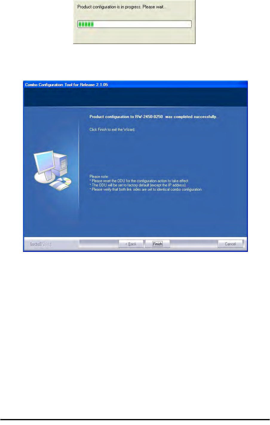
If you receive an error message Appendix H
RADWIN 1000/2000/5000 User ManualVersion 2.5.30p3 H-6
Upon successful completion of the configuration process, the following
termination window is displayed:
8. Click Finish to exit the Wizard as shown.
9. Repeat the whole process for the second ODU in the link.
If you receive an error message
The last stage above may terminate unsuccessfully due to an error. Error
messages are posted to a window like this:
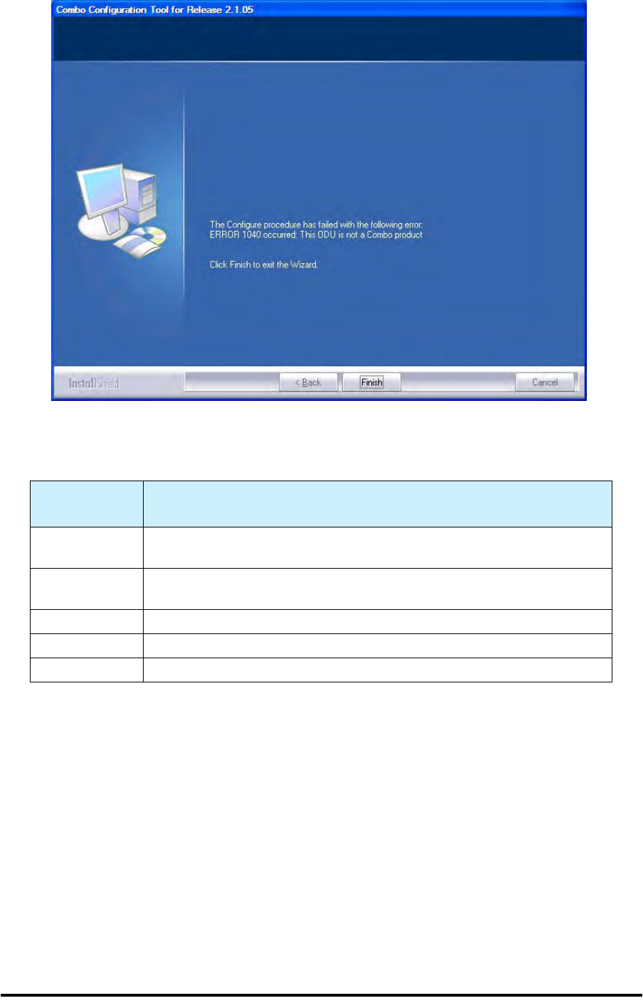
If you receive an error message Appendix H
RADWIN 1000/2000/5000 User ManualVersion 2.5.30p3 H-7
The following table sets out possible errors:
The only items requiring explanation are errors 940 and 1020.
Error 940 may arise as a result of an ODU firmware problem. Error 1020 will
appear for any reason not caught by the other entries in the table. In all
such cases, you should consult with RADWIN Customer Support.
Error Number
(nn) Error Text Message
Common mes-
sage preamble: The Configure procedure has failed with the following error: ERROR nn
occurred:
120 Failed to communicate with the ODU. Please verify the existence of a sta-
ble IP connection and try again.
940 Product is not identified.
1040 The ODU is not a Combo product.
1020 A configuration problem detected. Aborting.

RADWIN 1000/2000/5000 User ManualVersion 2.5.30p3 I-1
Appendix I
Regional Notice: French
Canadian
Procédures de sécurité
Généralités
Avant de manipuler du matériel connecté à des lignes électriques ou de
télécommunications, il est conseillé de se défaire de bijoux ou de tout autre
objet métallique qui pourrait entrer en contact avec les éléments sous ten-
sion.
Mise à la terre
Tous les produits RADWIN doivent être mis à la terre pendant l'usage cou-
rant. La mise à la terre est assurée en reliant la fiche d'alimentation à une
prise de courant avec une protection de terre. En outre:
• La cosse de masse sur l'IDU-C doit être constamment connectée à
la protection de terre, par un câble de diamètre de 18 AWG ou plus.
Le matériel monté sur rack doit être installé seulement sur des racks
ou armoires reliés à la terre
• Une ODU doit mise à la terre par un câble de diamètre de 12 AWG
ou plus
• Il ne doit pas y avoir de fusibles ou d'interrupteurs sur la connection
à la terre
De plus:
• Il faut toujours connecter la terre en premier et la déconnecter en
dernier
• Il ne faut jamais connecter les câbles de télécommunication à du
matériel non à la terre
• Il faut s'assurer que tous les autres câbles sont déconnectés avant
de déconnecter la terre

Protection contre la foudre Appendix I
RADWIN 1000/2000/5000 User ManualVersion 2.5.30p3 I-2
Protection contre la foudre
L'utilisation de dispositifs de protection contre la foudre dépend des exi-
gences réglementaires et de l'utilisateur final. Toutes les unités extérieures
RADWIN sont conçues avec des circuits de limitation de surtension afin de
minimiser les risques de dommages dus à la foudre. RADWIN conseille l'util-
isation d'un dispositif de parafoudre supplémentaire afin de protéger le
matériel de coups de foudre proches.
Matériel supplémentaire requis
L'équipement requis pour l'installation du matériel est le suivant:
• Pince à sertir RJ-45 (si un câble pré-assemblé ODU/IDU n'est pas
utilisé)
• Perceuse (pour le montage sur mur seulement)
• Câbles de terre IDU et ODU
• Clef 13 mm (½)
• Câble ODU - IDU si non commandé (type extérieur, CAT-5e, 4 paires
torsadées, 24 AWG)
• Colliers de serrage
• Ordinateur portable avec Windows 2000 ou Windows XP.
Précautions de sécurité pendant le montage de ODU
Avant de connecter un câble à l'ODU, la borne protectrice de masse (visse)
de l'ODU doit être connectée à un conducteur externe protecteur ou à un
pylône relié à la terre. Il ne doit pas y avoir de fusibles ou d'interrupteurs
sur la connection à la terre.
Seulement un personnel qualifié utilisant l'équipement de sécurité approprié
doit pouvoir monter sur le pylône d'antenne. De même, l'installation ou le
démontage de ODU ou de pylônes doit être effectuée seulement par des
professionnels ayant suivi une formation.
Pour monter l'ODU:
1. Vérifier que les supports de fixation de l'ODU sont correctement mis à la
terre.
2. Monter l'unité ODU sur le pylône ou sur le mur; se référer à la Installa-
tion sur pylône et mur au dessous.
3. Connecter la câble de terre au point de châssis sur l'ODU.
4. Relier le câble ODU-IDU au connecteur ODU RJ-45.
5. Visser les presses-étoupe de câbles pour assurer le scellement hermé-
tique des unités ODU.
6. Attacher le câble au pylône ou aux supports en utilisant des colliers clas-
sés UV.
7. Répéter la procédure sur le site distant.

Connecter la terre à IDU-C Appendix I
RADWIN 1000/2000/5000 User ManualVersion 2.5.30p3 I-3
Connecter la terre à IDU-C
Connecter un câble de terre de 18 AWG à la borne de masse de l'appareil.
L'appareil doit être constamment connecté à la terre.
Prudence
Ne pas se placer en face d'une ODU sous tension.
Prudence
• Les appareils sont prévus pour être installés par un personnel de ser-
vice.
• Les appareils doivent être connectés à une prise de courant avec une
protection de terre.
• Le courant CC du IDU-C doit être fourni par l'intermédiaire d'un dis-
joncteur bipolaire et le diamètre du câble doit être de 14 mm avec un
conduit de 16 mm.

Installation sur pylône et mur Appendix I
RADWIN 1000/2000/5000 User ManualVersion 2.5.30p3 I-4
Installation sur pylône et mur
L' ODU ou l'O-PoE peuvent être montés sur un pylône ou un mur.
Contenu du kit de montage ODU
Le kit de montage ODU comprend les pièces suivantes:
• une grande clame (voir figure I-1)
• une petite clame (voir figure I-2)
• un bras (voir figure I-3)
• quatre visses hex tête M8x40
• deux visses hex tête M8x70
• quatre rondelles plates M8
• trois rondelles élastiques M8
• deux écrous M8.
Figure I-1: grande clame Figure I-2: petite clame Figure I-3: bras
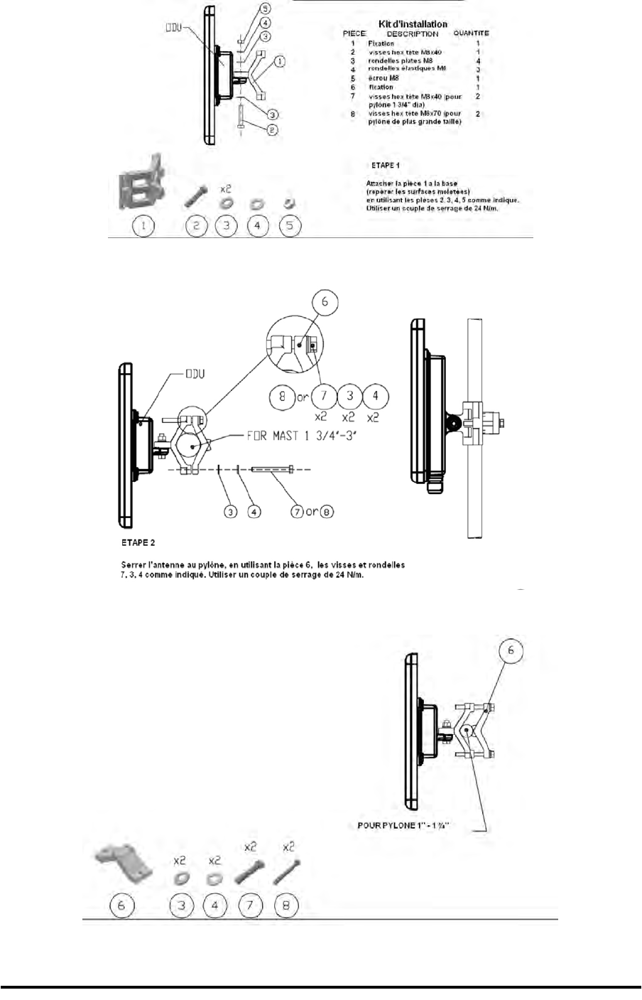
Montage sur un pylône Appendix I
RADWIN 1000/2000/5000 User ManualVersion 2.5.30p3 I-5
Montage sur un pylône
Figure I-4: Montage sur un pylône
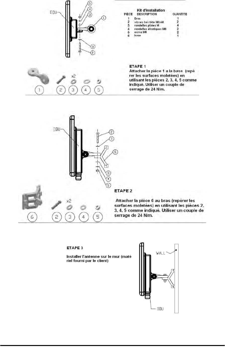
Montage sur un mur Appendix I
RADWIN 1000/2000/5000 User ManualVersion 2.5.30p3 I-6
Montage sur un mur
Figure I-5: Montage sur un mur

Montage d'une antenne externe Appendix I
RADWIN 1000/2000/5000 User ManualVersion 2.5.30p3 I-7
Montage d'une antenne externe
L'antenne externe optionnelle peut être montée sur un pylône.
Contenu du kit de montage d'une antenne externe
Le kit de montage d'une antenne externe comprend les pièces suivantes
• Douze rondelles plates
• Huit rondelles élastiques
• Huit écrous hex
• Quatre boulons
• Un support en U
• Un support à pivotement
• Deux courroies de fixation en métal
Pour installer une antenne externe sur un pylône:
1. Attacher le support en U à l'arrière de l'antenne en utilisant quatre ron-
delles plates, quatre rondelles élastiques et quatre écrous hex.
2. Attacher le support à pivotement au support en U en utilisant huit ron-
delles plates, quatre rondelles élastiques, quatre écrous hex et quatre
boulons.
3. Passer les deux courroies de fixation par les fentes verticales dans le sup-
port à pivotement.
4. Attacher l'antenne au pylône en utilisant les deux courroies de fixation .
Ajuster l'inclinaison nécessaire en utilisant l'échelle angulaire et serrer tous
les boulons et écrous à la position requise.

RADWIN 1000/2000/5000 User ManualVersion 2.5.30p3 Index 1
Index A
AAR 1-4
ACS 4-17, 6-20, F-8, F-8
aging time, ODU Bridge Mode 6-10
Air Interface 1-12, 1-12
Technical Specifications, general A-1
Alarms
Active 7-9
summary 7-14
Connector B-3
External , specification G-1
Antennas
Align with beeper 3-13
Aligning 3-13
bipolar 3-13
Buzzer signals 3-14
monopolar 3-14
Cable, grounding E-1
Connecting 3-13
Described 1-10
External
Mounting 3-7
Package Contents 3-5
External, Mounting C-3
Flat panel 1-11
Parabolic Dish 1-12
Settings 4-19, 5-18
types 1-8
Applications
Broadband Access 1-2
IP Backhaul 1-2
Private Networks 1-3
WiMAX 1-2
Automatic Adaptive Rate, see AAR 1-4
Automatic Channel Selection, see ACS
Automatic Repeat Request 1-4
B
backup
configuration file 6-2
ODU replacement 7-16
Beeper
mute 6-17
muting and restoring 6-3
restore 6-17
Bridge mode,Telnet commands 6-21
Buzzer, see Beeper
C
Changing link password 4-16
Channel, selecting 4-17, 5-12
Community Strings
Changing 6-16
Editing 6-15
Factory Default 6-14, F-2
Forgotten passwords 6-16
MIB F-2
passwords 4-4
Read-Only 6-14
Read-Write 6-14
Trap 6-14
Configuration Parameters 6-3
Configuring
Advanced 6-2, 6-9, 6-11, 6-12, 6-18
Air Interface 6-2
Air interface 5-1
Bridge mode 6-1
Community values. 6-1
contact person 6-2
Date and Time 6-2
Ethernet mode 6-1
Frequency channel 5-1
Security 6-2
Service parameters 5-1
System 6-2
System parameters 5-1
Transmit power 6-1
View Inventory 6-2
Connecting user equipment 4-17, 5-12
Customer Support 7-17
D
Date and time, setting 6-2, 6-7
Default log on password 4-4
E
Events
color codes 7-12
log 7-2, 7-4
priority 7-13
Index

RADWIN 1000/2000/5000 User ManualVersion2.5.30p3 Index 2
F
Factory Defaults 6-14, F-2
Reset to 6-19
Factory Setup
Restoring 7-17
FEC 4-21, 4-22, A-4, A-4
Forward Error Correction, see FEC
G
Gateway 6-2
Telnet display 6-20
I
IDUAging time 6-10
aging time, ODU Bridge Mode 6-10
Connecting to ODU 3-12
described 1-8
IDU-C
Alarm Connector B-3
Connectors B-4
Front panel 1-9
Described 3-10
LEDs 3-10, 3-11, 4-2
Mounting 3-8
Power connections 3-11, 3-12
Package Contents 3-4
Products 1-8
Indoor Unit, see IDU
Installation
Menu and Toolbar Functionality 4-10
Post Configuration main window 5-22
Post Installation main window 4-27
see Link, Installation
Installation Mode 6-3, 6-3, 6-12
Inventory 6-16
Displaying 6-12
IP address 6-2
Telnet display 6-20
K
Key Features of Radio Link
Advanced Air Interface 1-4
Capacity 1-3
Combo Frequency Products 1-4
Installation and management 1-4
Range performance 1-4
Security 1-5
Spectral Efficiency 1-3
Transmission (Tx) power 1-4
L
LBC 7-4
Browser warnings D-6
Calculations D-2
Climactic C Factors D-10
described D-1
Fresnel Zone, described D-13
Internal data D-1
Running D-3
User input D-1
Lightning and Grounding Guidelines E-1
LinkBudget Calculator, see LBC
Configuration 5-1
Overview 5-10
Step 1 - Start Wizard 5-11
Step 2- System Parameters 5-11
Step 3 - Channel Settings 5-12
Step 4 - Tx Power and Antenna Settings
5-18
Step 5 - Services 5-20
Step 6 - Summary and exit 5-21
default frequency 4-18
default Settings 4-9
Information 7-1
Air Interface Thresholds
BBER Threshold 7-9
RSL Threshold 7-9
Air Interface Thresholds, setting 7-9
Alarms
Active summary 7-14
Error detection and 7-14
output 7-15
saved 7-14
Compatibility 7-3
Trap messages 7-3
Events Log 7-4
Events log
Events references
trapbackground color 7-13
default colors 7-13
foreground color 7-12
Preferences 7-12
saving 7-13
Monitor log 7-4, 7-4
saving 7-4
Online Help 7-17
Performance data, explained 7-8
Performance monitoring 7-4
Performance Reports 7-5
Remote Power Fail Indication 7-15
“Dying-Gasp” circuit 7-15
Troubleshooting 7-16
Installation 4-7
ODU
Mast and Wall C-1
Overview 4-13
Step 1 - Start Wizard 4-14
Step 2 - System Parameters 4-14
Step 3 - Channel Settings 4-17
Step 4 - Tx Power and Antenna Settings

RADWIN 1000/2000/5000 User ManualVersion2.5.30p3 Index 3
4-19
Background 4-20
Step 5 - Services 4-25
Step 6 - Summary and Exit 4-26
Link ID 4-9, 4-15, 6-20, 7-16, 7-16, 7-17
Login 4-3
Login Errors
Incorrect IP Address 4-6
Incorrect password 4-6
Unsupported Device 4-5
Login showing Community Options 4-5
Manager Software 4-2
Name 4-15
Password 1-5, 7-17
changing 4-16
Post Configuration main window 5-22
Post Installation main window 4-27
Reinstalling/Realigning 7-3
Site names 4-15
Link Budget Calculator, see LBC 7-4
Link ID 4-9, 4-15, 6-20, 7-16, 7-16, 7-17
Link Site
Planning 2-1
Survey 2-1
Stage 1 - Preliminary Survey 2-2
Stage 2 - Physical Survey 2-3
Additional Indoor Site Requirements
2-4
Additional Outdoor Site Requirements
2-4
Stage 3 - RF Survey 2-4
Login Errors
Incorrect IP Address 4-6
Incorrect password 4-6
Unsupported Device 4-5
M
Management
Addresses 6-4
and trap addresses 6-1
Configuring the Site 6-2
Screen, Telnet 6-22
Manager Software
Change log on password 4-7
Events Log 5-8
Installing 4-1
Main window 5-1
Details pane 5-6
Main menu 5-3
Toolbar 5-2
main window 4-5
Monitor pane 5-7
Ethernet Service
5-7
Radio Interface, 5-7
Radio signal strength 5-7
Off-line functionality 4-6
Status Bar 5-9
Manual
Chapters by Audience 1-14
Conventions 1-16
Terminology 1-14
MIBAbout F-1
Community String F-2
Interface API F-1
Parameters F-4
Private F-2
Private Parameters F-5
Reference F-1
Supported Variables from the RFC 1213 F-4
Terminology F-1
Traps F-18
Parameters F-18
O
ODU 1-7
Bridge Mode
aging time 6-10
Connectorized 1-6, 1-7
described 1-6
form factors 1-7
Installation, Mast and Wall C-1
Integrated Antenna 1-6, 1-7
Mounting Kit C-1
Package Contents 3-2
Products 1-8
Replacing 7-16
With integrated antenna 1-10
P
Package, contents of 3-2
Password
Community 4-4, 4-4
Default 4-4
default log on 4-4
Link 1-5, 7-17
PC, Minimum Requirements 4-1
Performance
Monitor 7-2
Performance Monitoring, set time interval 7-4
PoEDescribed 1-9
PoE device, see PoE
Power over Ethernet, see PoE
Protection
External Lightning Surge Suppressors E-3
Grounding
Antenna cable E-1
IDUs E-2
ODUs E-2
Internal ESD Protection circuits E-7

RADWIN 1000/2000/5000 User ManualVersion2.5.30p3 Index 4
R
Radio Link
Accessories 1-13
Additional Tools and Materials Required 3-5
Connecting user equipment 3-12
Described 1-5
Documentation set 1-13
Hardware Installation
External Antennas 3-7
Indoor 3-8
Lightning protection 3-7
Mounting U 3-8
ODU 3-6
Outdoor 3-6
Outdoor connections 3-8
Sequence 3-5
Package Contents 3-2
IDU 3-4
ODU 3-2
Package contents
External Antennas 3-5
Transmission rates 4-22
Radio Outdoor Unit, see ODU
Replacing an ODU 7-16
restore configuration file 6-2
S
Safety Practices 3-1
Grounding 3-1
Preventing overexposure to RF energy 3-1
Selecting channel 4-17, 5-12
SiteConfiguration
Configuration Files 6-18
backup to 6-18
Configuration files
restore from 6-19
Configuration with Telnet 6-20
Dialog
Change Tx Power 6-4
Ethernet Properties 6-9
Configuring
Bridge 6-9
Maximum information rate 6-12
Ports Mode 6-11
Ethernet PropertiesIDU Aging time 6-
10
Functions 6-2
Inventory 6-12
Menu bar 6-2
Setting the date and time 6-7
View Air Iinterface details 6-3
VLAN Settings 6-5
Lost or forgotten VLAN ID 6-7
Priority number 6-6
VLAN ID 6-6
External Alarm Inputs 6-17
Reset site 6-19
Reset site to factory defaults 6-19
Reset site, preserve current configuration
6-19
Security Features 6-13
Community Strings 6-14
Editing 6-15
Forgotten paswwords 6-16
Initial log on defaults 6-15
Default Gateway 6-5
IP address 6-5, 6-5
Trap Destination 6-5
T
Technical Specifications
Air Interface A-5
Air Interface, general A-1
Configuration A-1
EMC A-5
Environmental A-5
Ethernet Interface A-4
Management A-5
Mechanical A-5
Power A-5
Radio A-2
Safety A-5
Trap messages 7-3
typical installation 3-5
U
User equipment, connecting 4-17, 5-12
W
Wiring Specifications B-1
Alarm
Connector
IDU-C B-3
Connectors
IDU-C B-4
User Port B-1
LANPorts B-1
ODU-IDU Cable B-1
Ports
LAN B-1
User Port Connectors B-1