Radwin RW2058U Outdoor radio unit operating in 5.8 GHz bands User Manual STW
Radwin Ltd. Outdoor radio unit operating in 5.8 GHz bands STW
Radwin >
Contents
- 1. Manual U1
- 2. Manual U2
- 3. Manual U3
- 4. Manual U4
- 5. Manual
Manual U2

RADWIN 1000/2000 User Manual Version 2.5p-4 4-1
Chapter 4
Link Installation: The
RADWIN Manager
This chapter explains how to use the RADWIN Manager to install a radio
link.
Installing theRADWIN Manager Application
Minimum System Requirements
The RADWIN Manager application is distributed on a CD. Operating system
specific PC resources required by the application are set out in table 4-1
below:
Requirements common to all systems are:
• Hard disk: 1 GB free space
• Network: 10/100BaseT NIC
• Graphics: 1024x768 screen resolution with 16 bit color
• Microsoft Explorer version 5.01 or later
Installing the Software
¾To install the RADWIN Manager application:
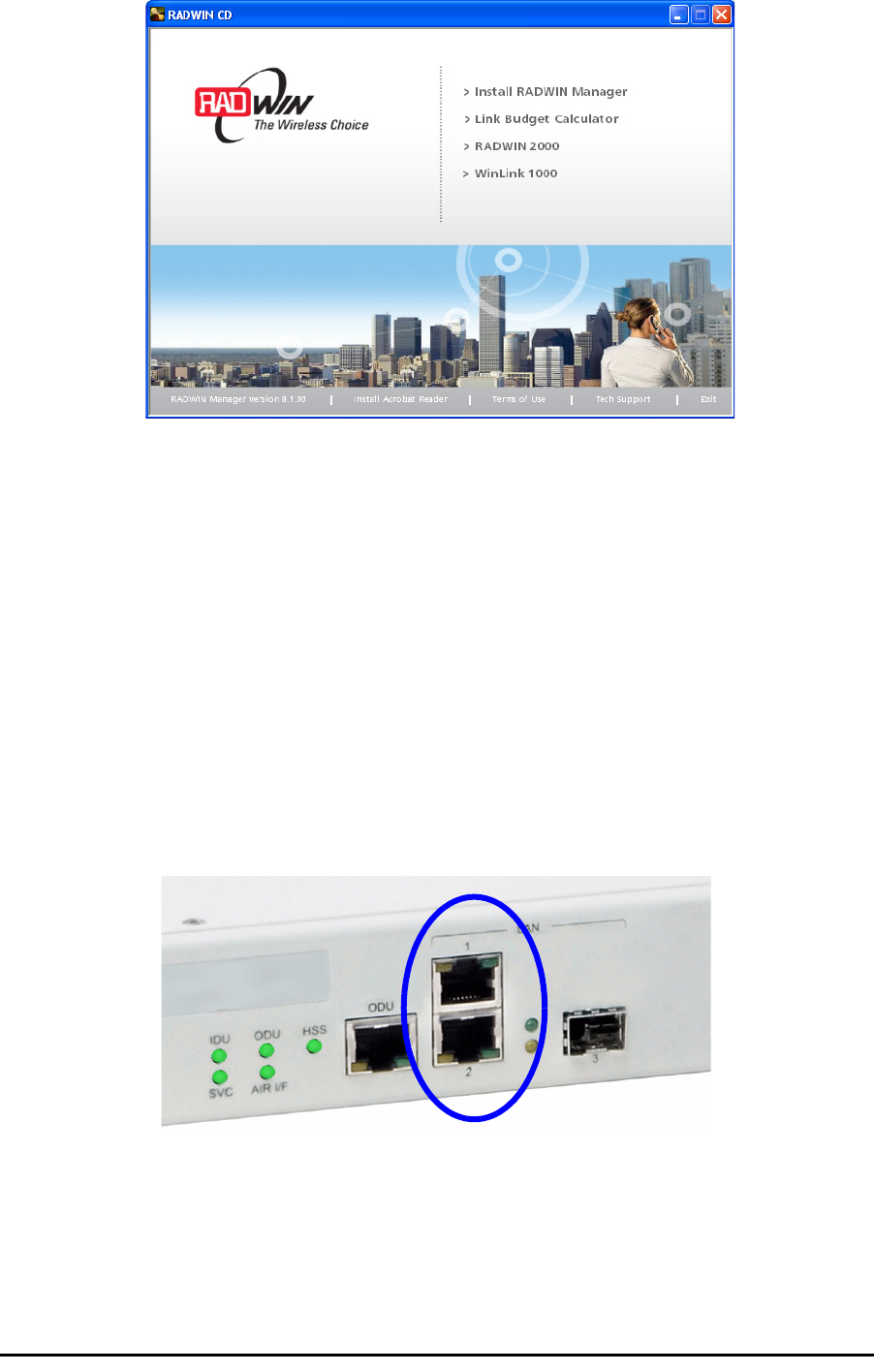
1. Insert the CD into the CD/DVD drive of your computer.
The CD opening screen appears:
Table 4-1: PC Requirements for the RADWIN Manager Application
Windows 2000 Windows XP Pro Windows Vista
Memory 128 MB 512 MB 1 GB
Processor P III P IV P IV Dual Core
Starting the RADWIN Manager Chapter 4
RADWIN 1000/2000 User Manual Version 2.5p-4 4-2
2. Choose Install RADWIN Manager and follow the on-screen instructions
of the installation wizard to complete the setup of the RADWIN Manager
application.
If the installation program fails to start, browse to your CD/DVD drive,
chose the setup.exe program and run it.
Any PC running the RADWIN Manager application can be used to configure
a RADWIN 1000/2000 link.
Starting the RADWIN Manager
¾To start the RADWIN Manager:
1. Connect the managing computer to one of the two LAN ports as shown
in figure 4-1 below:
Figure 4-1: LAN ports on the front panel of the IDU-C
If you are not using a direct connection as above, ensure that you have
IDU to managing computer connectivity (e.g. through a LAN).
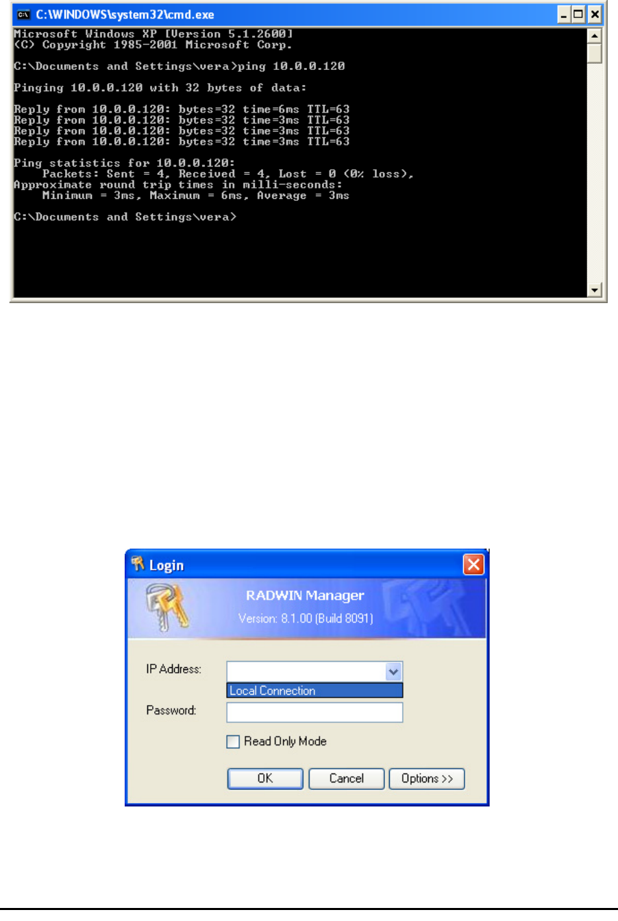
2. Check that you have connectivity to the ODU. You can do this by opening
up a command line session (Start|Run and then type, cmd). At the
command prompt, type
Starting the RADWIN Manager Chapter 4
RADWIN 1000/2000 User Manual Version 2.5p-4 4-3
ping 10.0.0.120
You should see something like this:
Figure 4-2: Pinging an uninstalled and unconfigured link
Any other response from ping means that the ODU is not responding.
Check your Ethernet connection and that both the the IDU and ODU are
switched on and then try again. If you do not succeed, seek assistance
from RADWIN Customer Support.
3. Dismiss the command line session.
4. Double-click the RADWIN Manager icon on the desktop, or click
Start|Programs|RADWIN Manager|RADWIN Manager.
The Login dialog box appears.
Figure 4-3: Login Screen
5. Type an IP address for the ODU (if you connect through a network), or
click Local Connection (if you are connected directly to the IDU port).

Starting the RADWIN Manager Chapter 4
RADWIN 1000/2000 User Manual Version 2.5p-4 4-4
6. Enter the password
7. If you are a user with Read-Write permission, click Options to enter the
Community options.
Warning
1. If you log in on Local Connection, but your physical connection is
not local (i.e. anything other than a direct connection between
the managing computer and the IDU), then any configuration
you carry out may affect other links in the network.
2. If you log in via an over-the-air IP address, you will receive a
warning. If you reset the site to which you are connected to
factory settings, you can lock yourself out of the Link.
3. Network login (IP address to the ODU) is recommended.
Note
The default IP address for the ODU is 10.0.0.120. The subnet mask is
255.0.0.0.
The actual IP address is defined during link configuration (see Site
Management: IP Address and VLAN on page 6-4).
Note
The default password is
admin
(see Changing the Log On Password on
page 4-7).
Note
RADWIN 1000/2000 is protected with Community passwords. A user may be
defined with read-only permission or with read-write permission (see
page 6-14 for more details).
Login Errors Chapter 4
RADWIN 1000/2000 User Manual Version 2.5p-4 4-5
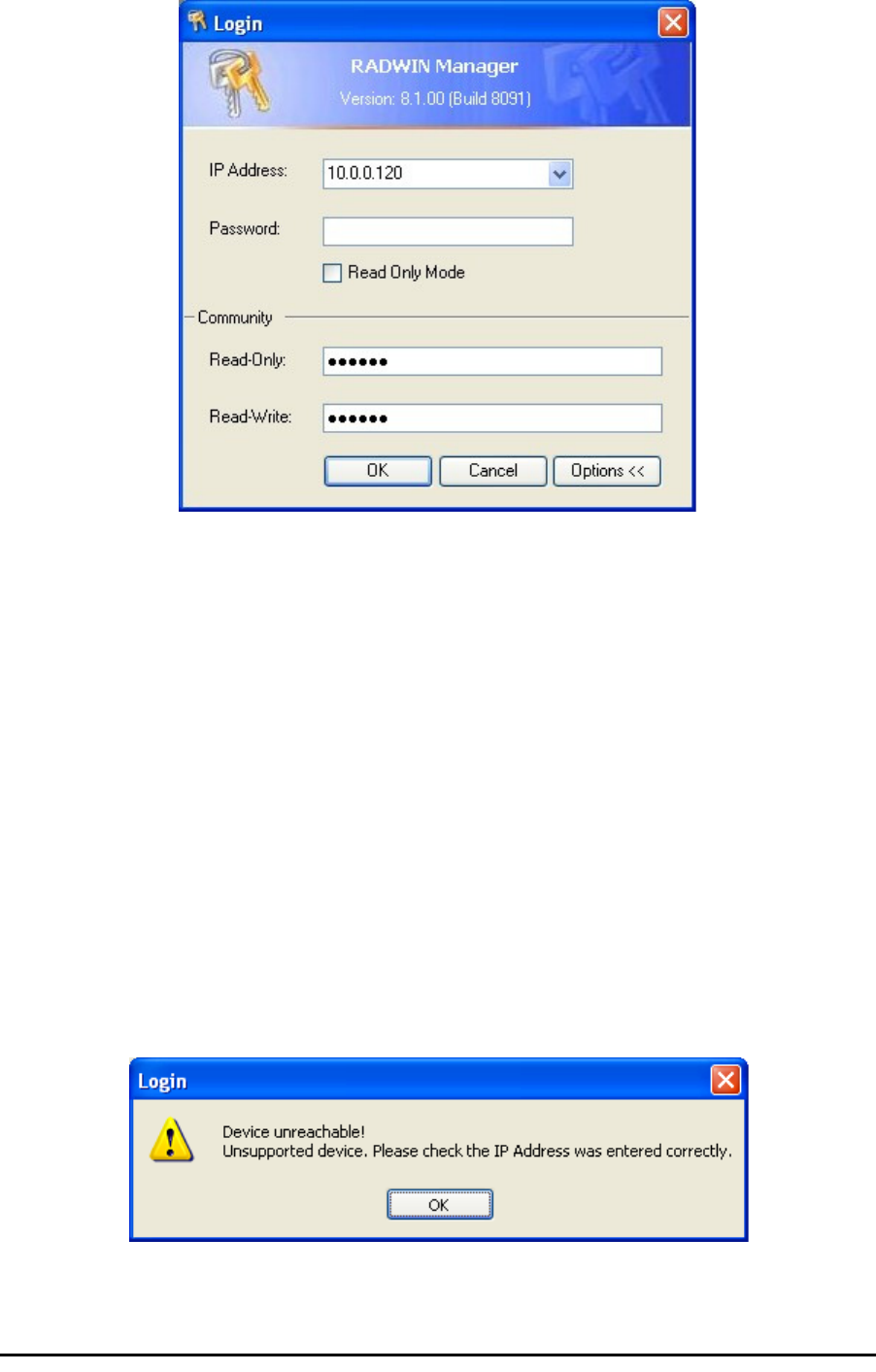
Figure 4-4: Login Screen with Community options visible
• If you are using the system for the first time, leave the default Com-
munity passwords,
netman
for read-write, and
public
for read-
only.
• If Community values were previously defined, enter them under
Community in the Read-Only or Read-Write boxes.
• If you are a user with read-only permission, click the Read Only
Mode check box.
The RADWIN Manager main window is displayed (see figure 4-7).
Login Errors
Unsupported Device
Attempting to connect to an unsupported device will result in the following
error message:
Figure 4-5: Unsupported device message
Incorrect IP Address Chapter 4
RADWIN 1000/2000 User Manual Version 2.5p-4 4-6
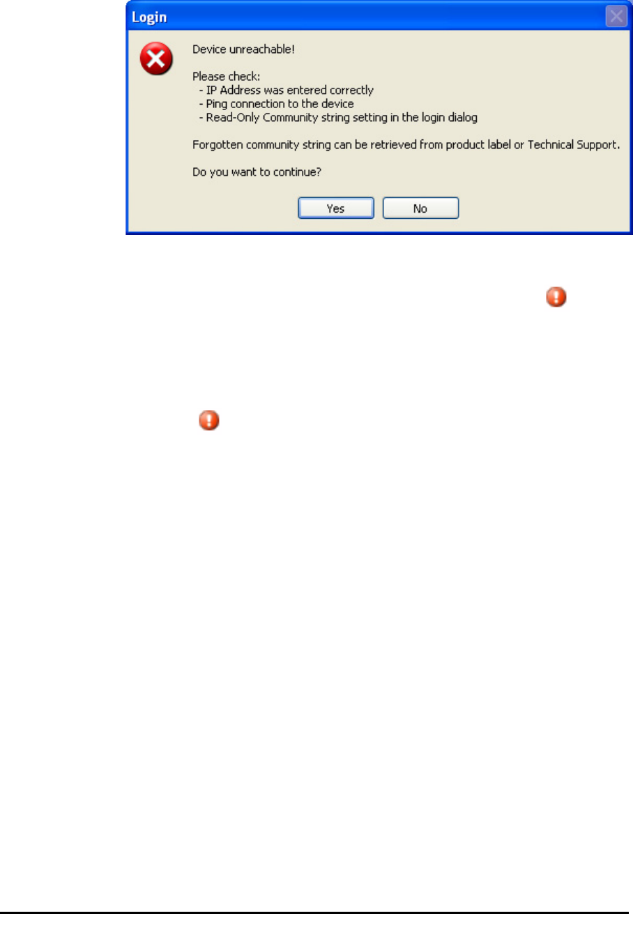
Incorrect IP Address
If the IP address chosen is invalid or the link is unreachable, the following
error message will be displayed:
Figure 4-6: Unreachable device message
In both of the above situations, you will see a warning graphic along-
side the IP Address field.
Incorrect Password
If you type an incorrect password in the Login screen, you will see a warn-
ing graphic alongside the password field.
Continuing without an IP Address
The RADWIN Manager provides limited “offline” functionality when there is
no accessible IDU/ODU. It is primarily for setting managing computer
related parameters and running the Link Budget Calculator. The offline func-
tionality is shown in table 4-2 below. The table does not show menu items
grayed out.

Changing the Log On Password Chapter 4
RADWIN 1000/2000 User Manual Version 2.5p-4 4-7
Changing the Log On Password
¾To change the log on password:
1. From the Tools menu, select Change Password.
The Change Password dialog box appears.
2. Enter the current password, and the new password.
3. Click OK to confirm.
Installing the Link: First steps
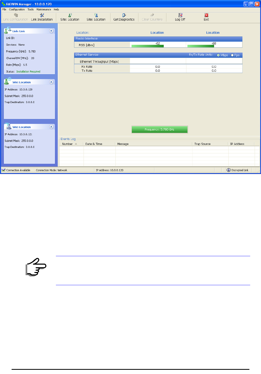
At this point the main window of the RADWIN Manager should be displayed:
Table 4-2: RADWIN Manager: Offline Functionality
Menu level
Function Reference
Top +1 +2
File
Log Off Return to Log On dialog.
Same as Log Off button
Exit Exit the RADWIN Manager.
Same as Exit button
Tools
Change
Password
Change the Log On pass-
word dialog page 4-7
Events Log page 7-10
Clear
Events
Clear local events log
Save to
File
Save events log data to a file
Help
RADWIN
Manager
Help
View online help version of
the User Manual
Link Budget
Calculator
Calculator opened in default
browser Appendix D
Get
Diagnostics
Information
Obtain system information page 7-1
About
RADWIN
Manager
RADWIN Manager build
information
Installing the Link: First steps Chapter 4
RADWIN 1000/2000 User Manual Version 2.5p-4 4-8
Figure 4-7: Opening RADWIN Manager window prior to installation
A detailed field by field description of the contents of the RADWIN Manager
main window may be found in chapter 5.
The procedure required to make the link functional has three phases:
1. Link Installation - which we will detail below.
Installation actually gets the link operational by setting the link parame-
ters. It uses a fixed channel at the lowest possible modulation, BPSK at
6.5Mbps and will work under the harsh interference condition.
2. Link Configuration - described in chapter 5.
Configuration provides much the same functionality as Installation, but
for a running link. A fallback to Installation mode is provided for situa-
tions which cannot be handled without resetting the link, such as
antenna realignment and IDU or ODU replacement.
The Link Installation and Configuration phases are both carried out with
Wizards, which “walk you through” the processes. The Wizards are visu-
ally quite similar and will be described in detail below.
Note
During the installation procedure, the definition of all parameters is
automatically applied to both sides of the link.

Default Settings Chapter 4
RADWIN 1000/2000 User Manual Version 2.5p-4 4-9
3. Site Configuration - described in chapter 6.
Site specific configuration for each side of the link is available at any time
- under a running link or under the restricted Installation mode.
Site Configuration consists of a set of panels, which may be invoked indi-
vidually in any order, as needed.
Default Settings
The default settings of the RADWIN 1000/2000 configuration parameters
are listed in table 4-3 below:
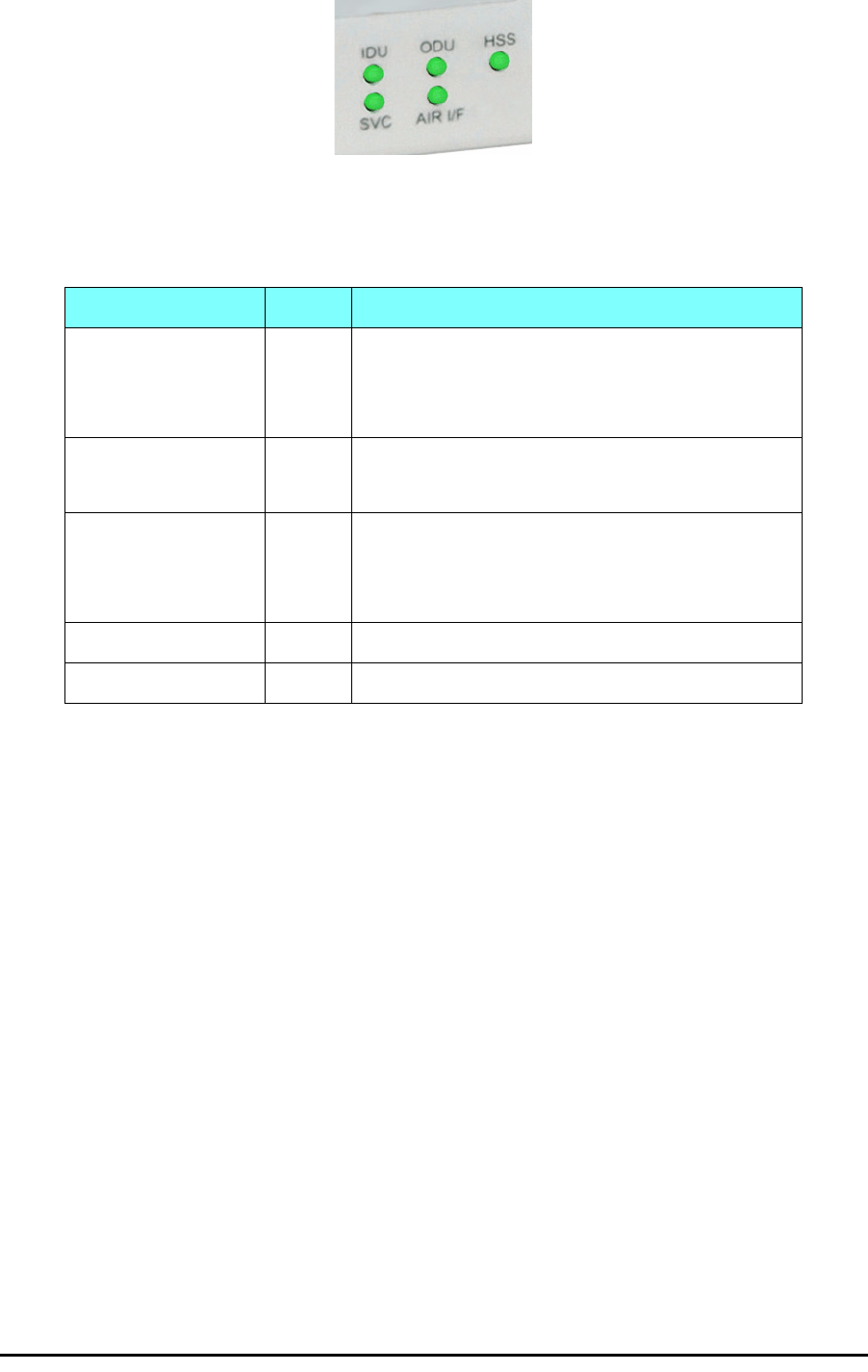
Front Panel LEDs on the IDU-C
The front panel LEDs on the IDU provide basic information about link sta-
tus.
Note
An installed and configured link can be returned to installation mode for re-
installation and configuration from last settings or from factory settings.
• Reversion to installation mode requires a complete break in the link
service
• Configuration mode may vary the service throughput and quality, but
without a service break
Table 4-3: Default Settings
Parameter Default Value
ODU IP Address 10.0.0.120
Subnet Mask 255.0.0.0
Trap destination 0.0.0.0
Manager Login password admin
Link ID Link
Site 1 Site
Site 2 Site
Link Password wireless-bridge
Rate Adaptive
Ethernet Configuration Auto Detect
Radio Link Failure Actions No action
Bridge or Hub mode Hub Mode, Aging time = 300 sec
Community values Read-write – netman
Read-only – public
Installation Menu and Toolbar Functionality Chapter 4
RADWIN 1000/2000 User Manual Version 2.5p-4 4-10
Figure 4-8: IDU-C Front Panel LEDs
The following table describes the indicators:
Installation Menu and Toolbar Functionality
The RADWIN Manager menu functionality is displayed in table 4-5. The
Toolbar buttons are detailed in table 4-6.
Table 4-4: Front Panel LEDs
Name Color Function
IDU
With Ethernet only
Green
Green
Red
During power-up only
IDU operational
Failure
ODU Green
Red
ODU-to-IDU communication link is operating
ODU-to-IDU communication link is disrupted
AIR I/F Green
Orange
Red
Wireless link is synchronized
During installation mode only
Wireless link lost synchronization
SVC Off
HSS Off

Installation Menu and Toolbar Functionality Chapter 4
RADWIN 1000/2000 User Manual Version 2.5p-4 4-11
Table 4-5: RADWIN Manager main menu functionality
Menu level
Function Reference
Top +1 +2
File
Log Off Return to Log On dialog.
Same as Log Off button
Exit Exit the RADWIN Manager.
Same as Exit button
Configuration
Link
Configuration
Run the Configuration Wiz-
ard. Not available in
installation mode
1 Configure
<Site 1 name>
Provides limited configura-
tion for site. Has a path to
return to installation
mode
2 Configure
<Site 2 name>
Provides limited configura-
tion for site. Has a path to
return to installation
mode
Link Installation
Runs the Installation Wiz-
ard. Not available in
configuration mode
Tools
Performance
Monitoring
Report
Active Alarms
1 <Site 1 name> Shows active alarms for
<Site 1 name>
2 <Site 2 name> Shows active alarms for
<Site 1 name>
Change
Password
Change the Log On pass-
word dialog page 4-7
Events Log
page 7-10
Clear Events Clear local events log
Save to File Save events log file
Preferences Local preferences dialog

Installation Menu and Toolbar Functionality Chapter 4
RADWIN 1000/2000 User Manual Version 2.5p-4 4-12
Maintenance
Clear counters Disabled
Loopbacks Disabled
Reset 1 <Site 1 name> Reset <Site 1 name> ODU
2 <Site 2 name> Reset <Site 2 name> ODU
Help
RADWIN
Manager Help
View online version of the
User Manual
Link Budget
Calculator
Calculator opened in
default browser Appendix D
Get Diagnostics
Information
Obtain system information page 7-1
About RADWIN
Manager
Manager build and system
information
Table 4-6: RADWIN Manager Toolbar
Item Description
Link Configuration Changes configuration parameters of an operating wireless link;
assigns text files for storing alarms, statistics and configuration
data. This button is disabled until a link installation has
been completed
Link Installation Performs preliminary configuration of the system. This button is
disabled after the link is installed
Site: <Site 1 name> Opens the Site configuration dialog for Site A. Same as
Configuration | 1 Configure <Site 1 name>
Site: <Site 2 name> Opens the Site configuration dialog for Site B. Same as
Configuration | 2 Configure <Site 2 name>
Get Diagnostics Obtain system information
Clear Counters Disabled
Log off Closes the current session and logs off RADWIN Manager
Exit Exits RADWIN Manager
Table 4-5: RADWIN Manager main menu functionality (Continued)
Menu level
Function Reference
Top +1 +2
Installing the Link: Overview Chapter 4
RADWIN 1000/2000 User Manual Version 2.5p-4 4-13
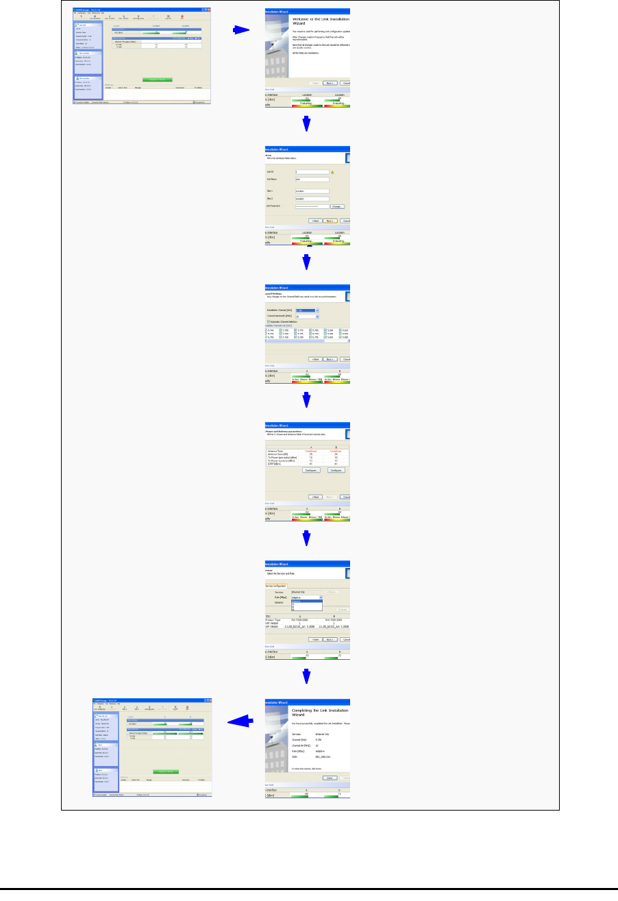
Installing the Link: Overview
The Installation wizard has seven steps as shown in table 4-7 below.
Table 4-7: Link Installation Wizard
1Wizard welcome
2
System parameters
•Link ID
• Site details
3Channel settings - ACS
Configuration
4Tx power and antenna
settings
5Services - Adaptive or
fixed
6Wizard summary and
completion
Installing the Link: Step 1, Start the Wizard Chapter 4
RADWIN 1000/2000 User Manual Version 2.5p-4 4-14
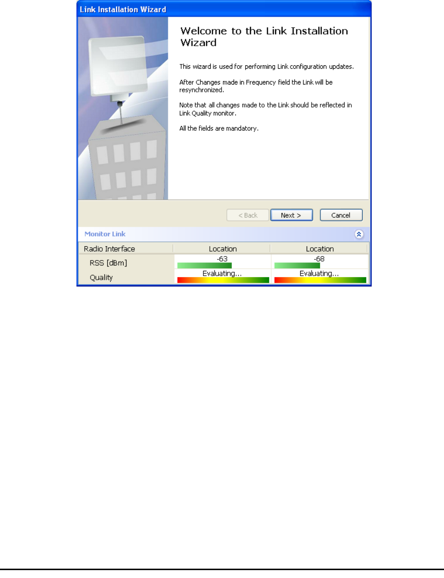
Installing the Link: Step 1, Start the Wizard
In the tool bar of the RADWIN Manager main window, click the Link
Installation button. The Link Installation button is only accessible if anten-
nas are properly aligned. If this box is “grayed out”, you should align the
antennas as set out in Connecting and Aligning ODUs / Antennas on
page 3-12.
The Installation Wizard opens:
Figure 4-9: Link Installation Wizard
The bottom data area reproduces the corresponding data from the main
window - which the above panel obscures. See page 5-7 for a field by field
description of this data area.
Click Next to proceed with the installation procedure.
Installing the Link: Step 2, System Parameters
The system dialog box opens:
Installing the Link: Step 2, System Parameters Chapter 4
RADWIN 1000/2000 User Manual Version 2.5p-4 4-15
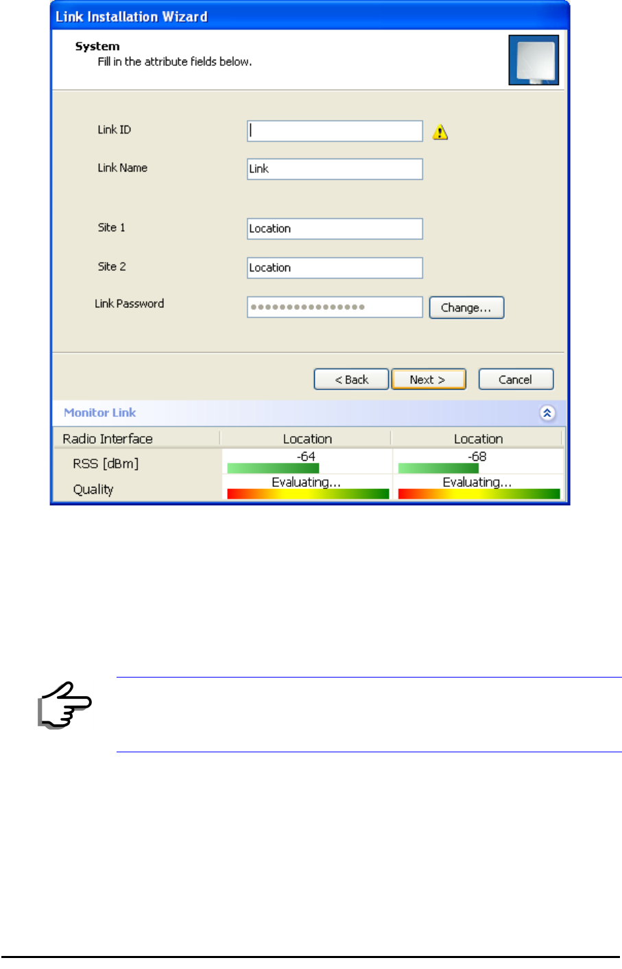
Figure 4-10: : Installation Wizard, System dialog box
¾To complete Installation Step 2:
1. Enter a Link ID. (Link ID - must be unique for each link in the area). The
Link ID must include at least eight alphanumeric characters. Up to 24
characters are allowed.You should use a Link ID composed of both
alphabetic and numeric characters.
2. Enter a Link Name for the link identification. The default name is “Link”.
You should change it.
3. Enter names for Site 1 and Site 2. The default names are both “Loca-
tion”. You should change them. Throughout this manual, we use A for
Site 1 and B for Site 2.
Note
Both sides of a link must have the same Link ID.
Changing the Link Password Chapter 4
RADWIN 1000/2000 User Manual Version 2.5p-4 4-16
4. Optionally enter a new Link Password.
5. Click Next.
The default link with a rate of 6.5 Mbps is evaluated.
The Channel Setting dialog box appears. Proceed to Installing the
Link: Step 3, Channel Settings, below.
Changing the Link Password
The default password is
wireless-bridge
. Optionally, you can change the
link password as explained here.
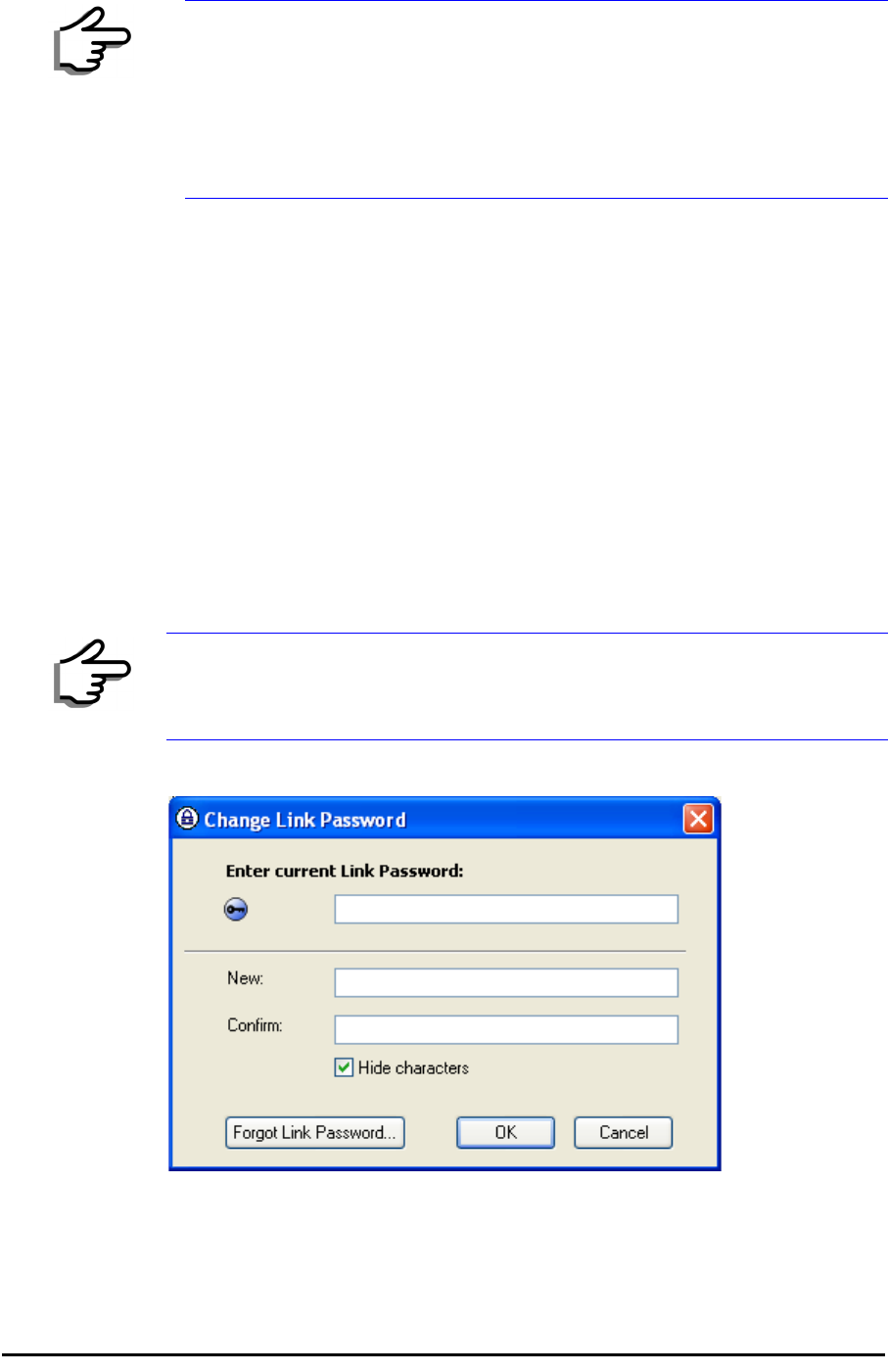
¾To change the link password:
1. Click the Change button in the System dialog box.
The Change Link Password dialog box opens.
Figure 4-11: Change Link Password dialog box
2. Enter the current link password (The default link password for a new
ODU is wireless-bridge).
Note
If the Link Password is incorrect a link is established but configuration
cannot be performed and no services are available. A new link password
may be obtained from RADWIN Customer Support or use the alternative
password supplied with the product. (see for more details).
The link password is peculiar to the link itself and should not be confused
with the RADWIN Managerlog on password.
Note
Use the Hide characters check box for maximum security
Installing the Link: Step 3, Channel Settings Chapter 4
RADWIN 1000/2000 User Manual Version 2.5p-4 4-17
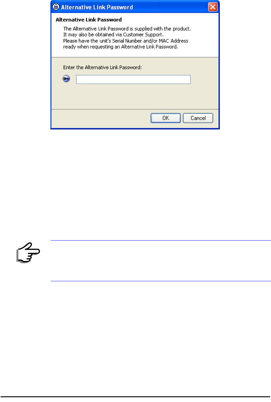
If you have forgotten the Link Password, click the Forgotten Link Pass-
word button. The following window is displayed:
Figure 4-12: Lost or forgotten Link Password recovery
Follow the instructions to use the Alternative Link Password, and click OK
to finish. You are returned to the window in figure 4-11 above. Con-
tinue with the next step.
3. Enter a new password.
4. Retype the new password in the Confirm field.
5. Click OK.
6. Click Yes when asked if you want to change the link password.
7. Click OK at the Password changed success message.
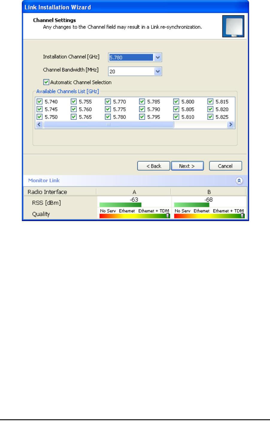
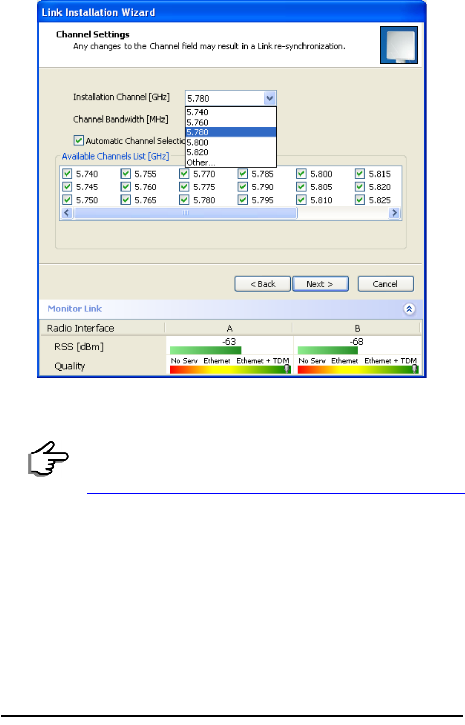
Installing the Link: Step 3, Channel Settings
RADWIN 1000/2000 systems have a feature called Automatic Channel
Selection (ACS). In the event of sync loss, ACS chooses the first available
channel in a list of monitored channels nominated in the Channel settings
window of figure 4-13 below. A channel switch takes place sufficiently fast
as to ensure no loss of service.
Note
• Restoring Factory Defaults returns the Link Password to
wireless-
bridge
.
• If the link is inactive, then the link password may also be changed
from the Site Configuration dialogs. See page 6-14.
Installing the Link: Step 3, Channel Settings Chapter 4
RADWIN 1000/2000 User Manual Version 2.5p-4 4-18
Figure 4-13: Channel Settings - Automatic Channel Selection
The default frequency for the product is shown.
¾To select channels to be used by the link:
1. Select the main frequency from the Installation Channel box.
Installing the Link: Step 4, Tx Power and Antenna Settings Chapter 4
RADWIN 1000/2000 User Manual Version 2.5p-4 4-19
Figure 4-14: Channel Settings - Showing available installation rates
2. Click the check box if Automatic Channel Selection is required.
3. The Available Channels List contains all of the allowable channels for the
link. Check the channels that can be automatically selected.
Selecting a new channel causes the system quality to change. The Qual-
ity bar provides an indication of the link quality from poor (red) to good
(green) as shown in the bottom of figure 4-13 above.
4. Click Next.
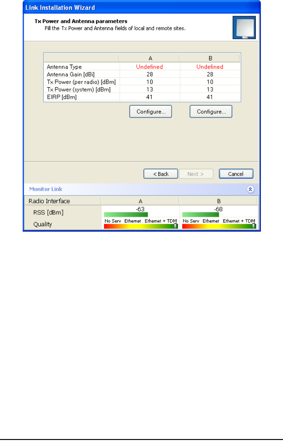
Installing the Link: Step 4, Tx Power and Antenna Settings
The Tx Power and Antenna Parameters dialog appears.
Note
For version 2.1, channel bandwidth is set to 20 MHz and cannot be changed.
General Chapter 4
RADWIN 1000/2000 User Manual Version 2.5p-4 4-20
.
Figure 4-15: Transmission Power and Antenna Parameters
The choice of Tx power, antenna gain and cable loss determines the EIRP
and is affected by such considerations as radio limitations and regulatory
restrictions.
Before proceeding to antenna installation details, the following background
information should be considered:
General
Each RADWIN 1000/2000 ODU is made of two radio transceivers (radios).
The radios make use of algorithms that utilize both polarization and space
diversity resulting in enhanced capacity, range and link availability. The
number of antennas (i.e. radios) used is determined by user configuration
and by automatic system decisions, explained below.
Dual Antennas at Both Sites
Using dual antennas at both sites (single bipolar antenna or two monopolar
antennas) enables the use of MIMO technology. With MIMO the system
doubles the link capacity. At the same time, it keeps the same rate and
modulation per radio as was used with single antenna, thus increasing
capacity, range and availability.

Single Antennas at Both Sites Chapter 4
RADWIN 1000/2000 User Manual Version 2.5p-4 4-21
For example with a dual antenna RADWIN 1000/2000 can transmit at mod-
ulation of 64QAM and FEC of 0.83 and get an air rate of 130 Mbps, com-
pared to 65 Mbps with single antenna.
To work in this mode, each antenna port must be connected to an antenna,
the RSS level in both receivers should be balanced and a minimal separation
between the antennas must be maintained. (For example, by using dual
polarization antennas a cross polarization separation is attained).
Upon selecting Antenna Type as Dual, RADWIN 1000/2000 automatically
doubles the air rates.
RADWIN Manager indicates a case of unbalanced RSS between the two
antennas.
Single Antennas at Both Sites
By selecting a single antenna at both sites the ODUs operate with a single
radio that is connected to the ANT 1 connector. The second radio is auto-
matically shut down.
Single and Dual Antennas
In this mode one of the sites uses the ODU with a single antenna while the
other site uses the ODU with a dual antenna.
The advantages in this mode in comparison to using a single antenna in
both sites are doubled total Tx power and additional polarization and/or
space diversity.
RADWIN 1000/2000 automatically switches to this mode if one of the ODUs
is connected to a dual antenna or if the RSS at one of the ODU receivers is
below minimal level.
The air rates used in this mode are same as when using single antennas in
both sites.

Considerations for Changing Antenna Parameters Chapter 4
RADWIN 1000/2000 User Manual Version 2.5p-4 4-22
The rates used by RADWIN 1000/2000 are shown in Table 4-5 below:
Considerations for Changing Antenna Parameters
Let:
maxAllowedTx Power denote the maximum Tx Power practically avail-
able from an ODU. It appears as Tx Power per Radio in
figure 4-16 below.
maxRegEIRP denote the maximum EIRP available by regulation. It will be
determined by three factors:
• per band/regulation
• per channel bandwidth
•antenna gain
It appears in figure 4-16 as Max EIRP.
maxRegTxPower denote the maximum regulatory Tx Power for the
equipment, also having regard the above three points
Table 4-8: RADWIN 1000/2000 Transmission rates
Radio Modulation FEC Air-Rate
[Mbps]
Single BPSK 1/2 6.5
Single QPSK 1/2 13
Single QPSK 3/4 19.5
Single 16QAM 1/2 26
Single 16QAM 3/4 39
Single 64QAM 2/3 52
Single 64QAM 3/4 58.5
Single 64QAM 5/6 65
Dual BPSK 1/2 13
Dual QPSK 1/2 26
Dual QPSK 3/4 39
Dual 16QAM 1/2 52
Dual 16QAM 3/4 78
Dual 64QAM 2/3 104
Dual 64QAM 3/4 117
Dual 64QAM 5/6 130
Considerations for Changing Antenna Parameters Chapter 4
RADWIN 1000/2000 User Manual Version 2.5p-4 4-23
maxODUTxPower denote the maximum Tx Power of the ODU, itself
depending on the air rate used.
Then, the following relationship must be satisfied:
... (*)
These parameters are controlled as follows:
¾To set Tx power and configure antennas:
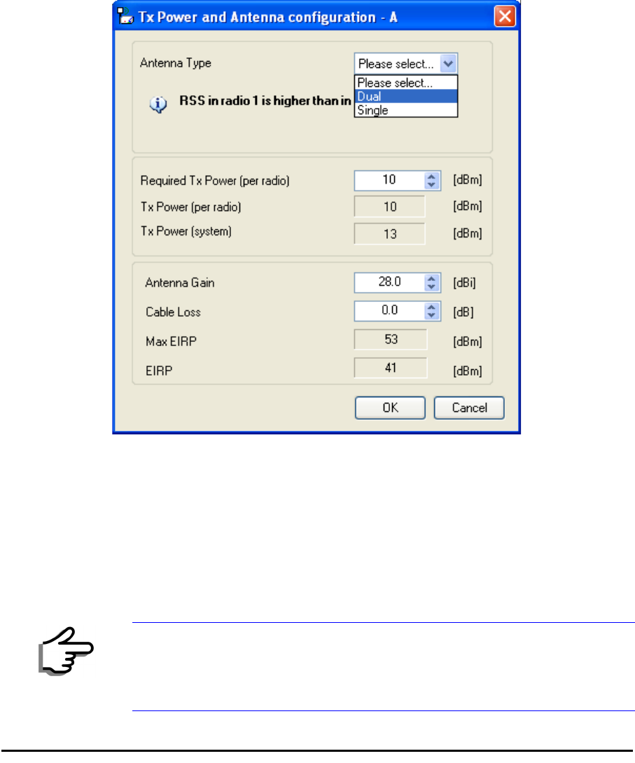
1. Click the Configure buttons in turn to configure the antennas on both
sides of the link. Each one offers a dialog like this:
Figure 4-16: Antenna configuration dialog with opened type selection
2. Choose the antenna type and required transmission (Tx) power for the
first site and click OK. Repeat the process for the second site.
The Tx power (per radio) indicates the power of each radio inside the
ODU and is used for Link Budget Calculations. The Tx power (System)
shows the total transmission power of the ODU and is used to calculate
the EIRP according to regulations.
Note
To see the relationship between Tx Power (radio) and TX Power (system),
note that so that if you double the power in
milliWatts (for two radios) then dBm will increase by .
maxAllowedTxPower min maxRegEIRP
AntennaGain CableLoss maxRegTxPower,+–
(
)
≤
dBm 10 milliWatt
10
log×=
10 2 3≈
10
log×
Considerations for Changing Antenna Parameters Chapter 4
RADWIN 1000/2000 User Manual Version 2.5p-4 4-24
3. Set the Antenna Gain and Cable Loss. If do this you will receive a warn-
ing message:
Figure 4-17: Antenna parameters change warning
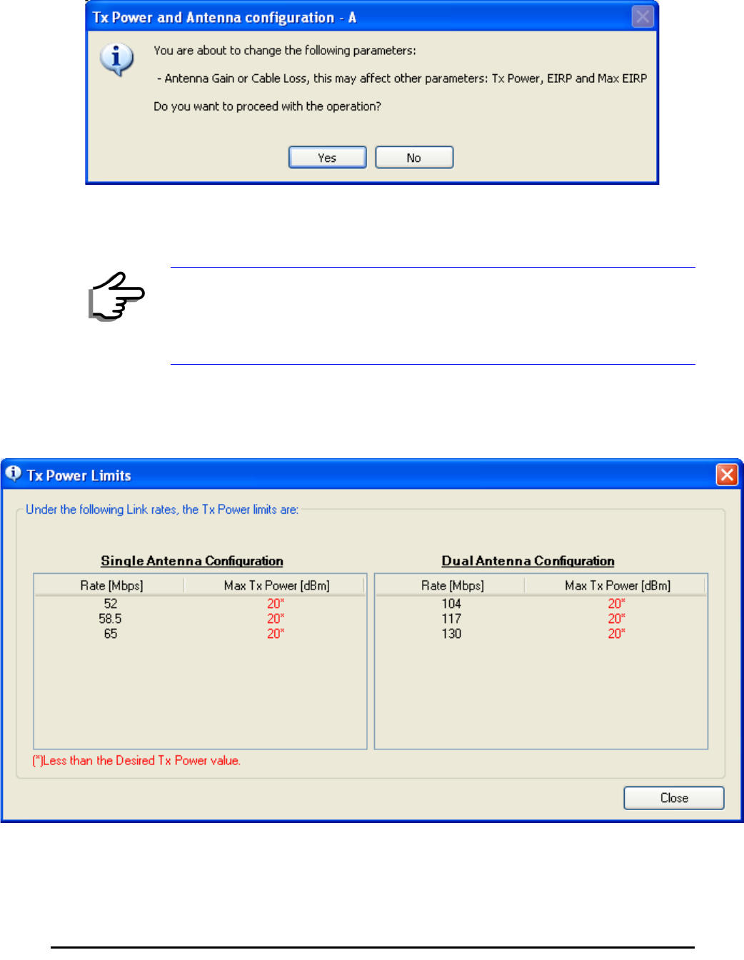
If inequality (*) above is violated, then the following warning window is
displayed:
Figure 4-18: Tx Power Limits
The precise relationship between the items in inequality (*) and the win-
dow of figure 4-16 is follows:
Note
• The Max EIRP level will be automatically set according to the selected
band and regulation.
• The EIRP level is the sum of the System Tx power and the Antenna
Gain minus the Cable Loss.
Installing the Link: Step 5, Services Chapter 4
RADWIN 1000/2000 User Manual Version 2.5p-4 4-25
• Required Tx Power (per radio) will be adjusted down to the
lesser of the value entered and maxAllowedTxPower
•TxPower (system)is maxAllowedTxPower + 3 (for 2 radios)
•Max EIRP is maxRegEIRP.
•EIRP is maxAllowedTx Power + Antenna Gain - Cable
Loss
The table in figure 4-18 only shows rates where the maximum Tx
Power is the limitation, rather than regulations.
When you close the window of figure 4-18, the change you requested
will not be honored, and you will need to try again.
4. When you are finished with Tx Power configuration, Click Next.
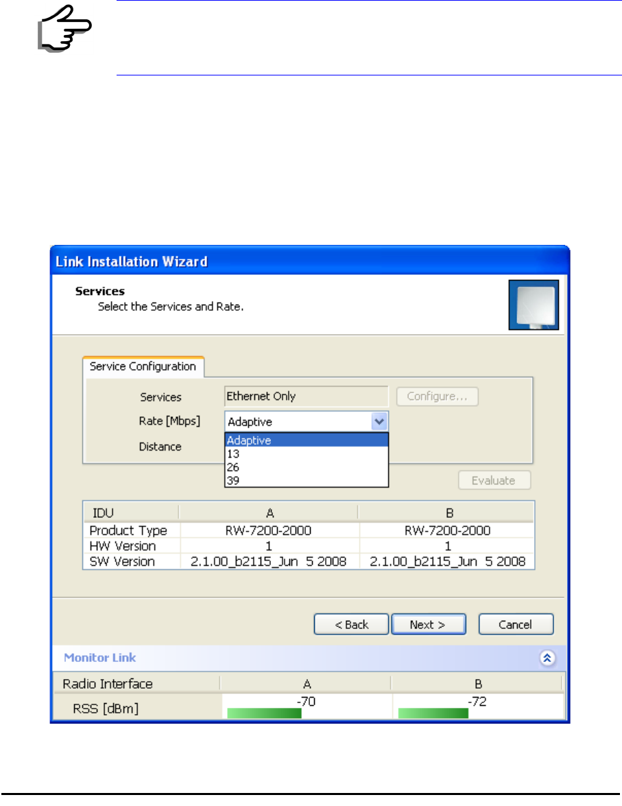
Installing the Link: Step 5, Services
The Services dialog appears:
Figure 4-19: Services and Rates dialog
Note
Recall that maxAllowedPower and maxEIRP are regulatory. In an
unregulated environment, the only limit is maxODUTxPower.
Installing the Link: Step 6, Installation Summary and Exit Chapter 4
RADWIN 1000/2000 User Manual Version 2.5p-4 4-26
For version 2.1, Ethernet Only is the only available service. You may choose
a specific modulation rate or use Adaptive.
¾To choose a modulation rate:
1.Choose Adaptive or one of the available rate (see page 1-3 for informa-
tion about Automatic Adaptive Rate).
2. Click Next to continue.
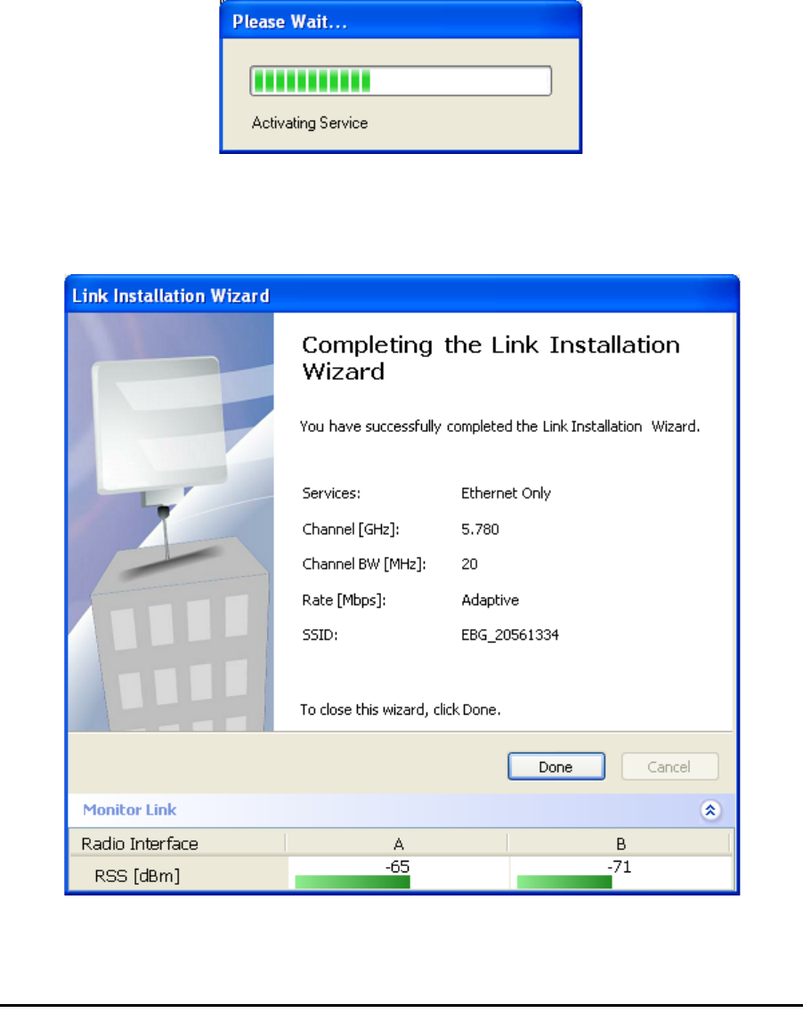
The service is activated as show below:
Installing the Link: Step 6, Installation Summary and Exit
Figure 4-20: Installation Wizard Exit Summary
Click Done to return to the main window.
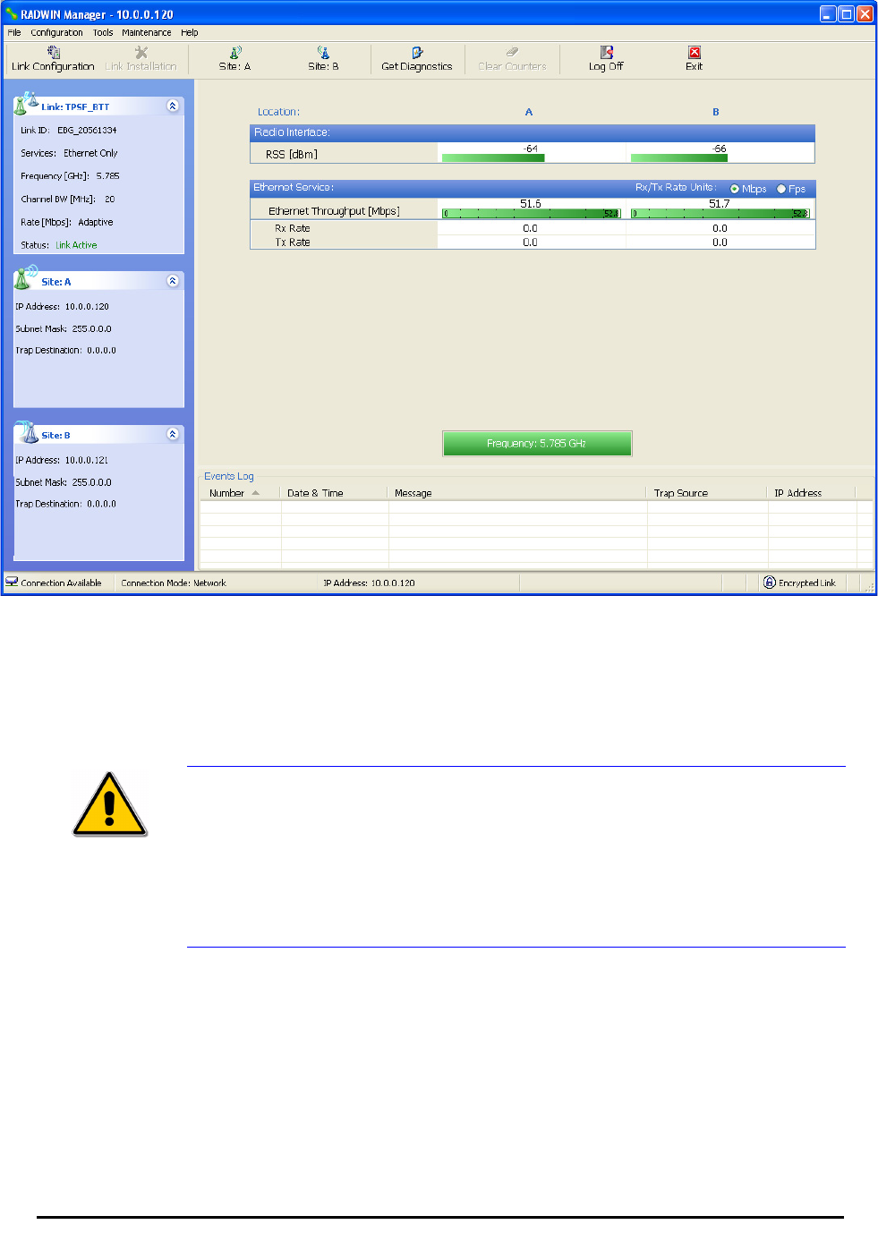
Installing the Link: Step 6, Installation Summary and Exit Chapter 4
RADWIN 1000/2000 User Manual Version 2.5p-4 4-27
The main window now reflects the installation:
Figure 4-21: Main window of the manager after installation
¾To verify the installation:
• Verify that the Radio Signal Strength (RSS) is according to expected
results as determined by the Link Budget Calculator.
Caution
Installation mode, as described above, may be re-entered using
Configuration | 1 Configure Site A and Installation Mode the Site
Configuration dialog. Some Installation mode functionality may cause a
break in link service.
If you can accomplish link changes without breaking the service, always
prefer to use Configuration mode, described in chapter 5.

RADWIN 1000/2000 User Manual Version 2.5p-4 5-1
Chapter 5
Configuring the Link
This chapter describes the link configuration procedure, which is performed
after the installation of both sides of the RADWIN 1000/2000 link, as set out
in chapters 3 and 4.
Link configuration uses a Link Configuration Wizard to redefine the configu-
ration parameters and fine-tune an operational link. Both sides of the link
are configured simultaneously.
The following parameters are configured using the Link Configuration Wiz-
ard:
• System parameters
• Channel settings
• Transmission power and antenna settings
•Service parameters
Link Configuration: Getting Started
The Main Window of the RADWIN Manager
Ensure that the RADWIN Manager is running.
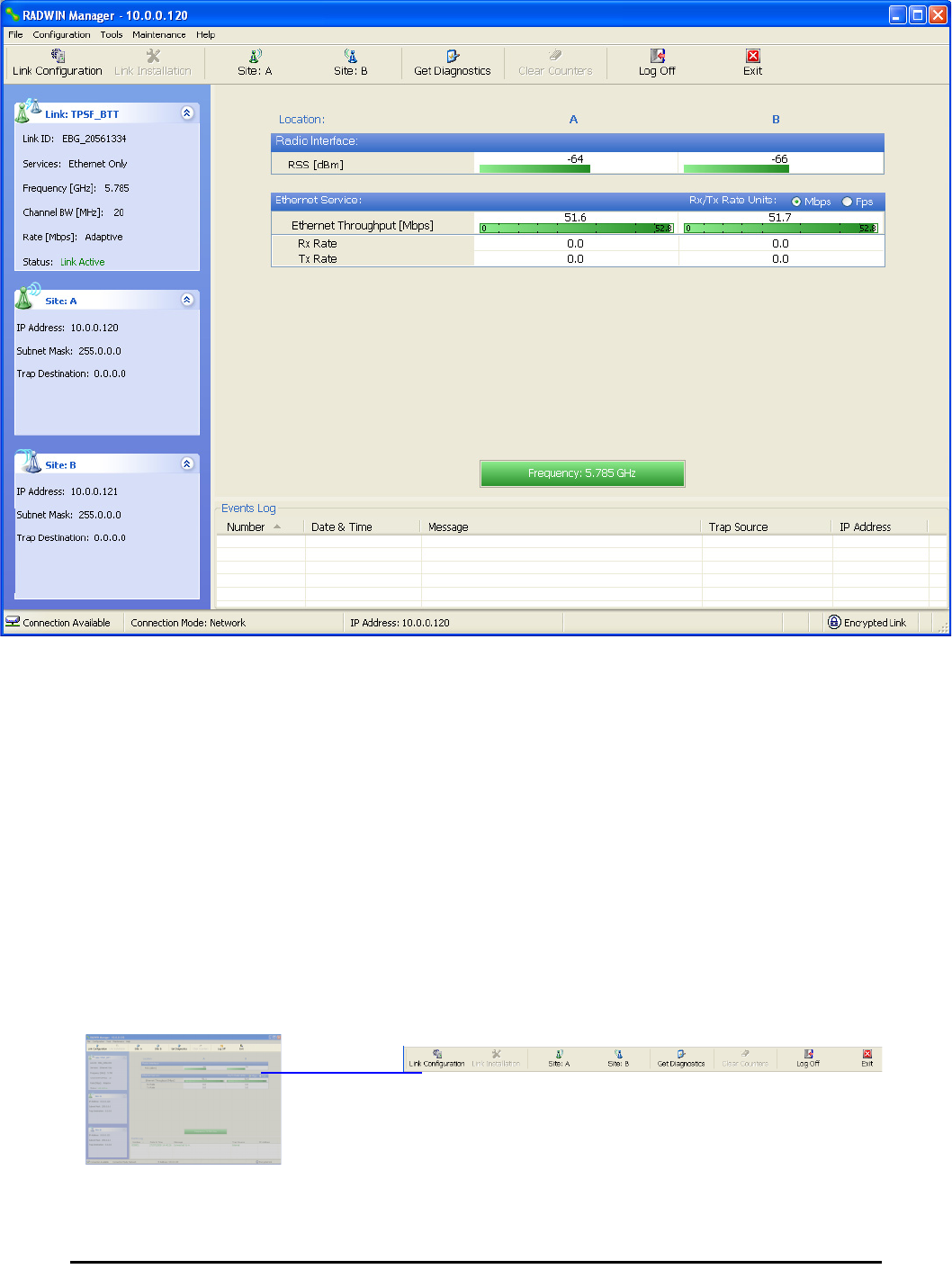
The main window should look similar to that in figure 5-1:
The RADWIN Manager Toolbar Chapter 5
RADWIN 1000/2000 User Manual Version 2.5p-4 5-2
.
Figure 5-1: Main window, Wireless Link is Active
Before starting a configuration session, make sure that a communication
link exists between the two sides of the link.
The Link Status indication bar must be green. In the Link Status panel, the
Status field should show Link Active in green.
The main window of the RADWIN Manager contains a large amount of
information about the link. Before proceeding to details of link configuration
we set out the meaning of each item in the main window.
The RADWIN Manager Toolbar
In configuration mode, the RADWIN Manager toolbar contains the following
buttons:
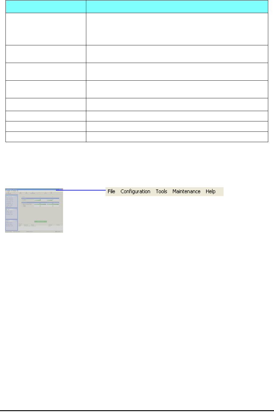
The RADWIN Manager Main Menu Chapter 5
RADWIN 1000/2000 User Manual Version 2.5p-4 5-3
The RADWIN Manager Main Menu
The RADWIN Manager menu, is shown in table 5-2 below:
Table 5-1: RADWIN Manager Toolbar
Item Description
Link Configuration Changes configuration parameters of an operating wireless link;
assigns text files for storing alarms, statistics and configuration
data. This button is disabled until a link installation has
been completed
Link Installation Performs preliminary configuration of the system. This button is
disabled after the link is installed
Site: <Site 1 name> Opens the Site configuration dialog for Site A. Same as
Configuration | 1 Configure <Site 1 name>
Site: <Site 2 name> Opens the Site configuration dialog for Site B. Same as
Configuration | 2 Configure <Site 2 name>
Get Diagnostics Obtain system information
Clear Counters Disabled
Log off Closes the current session and logs off RADWIN Manager
Exit Exits RADWIN Manager

The RADWIN Manager Main Menu Chapter 5
RADWIN 1000/2000 User Manual Version 2.5p-4 5-4
Table 5-2: RADWIN Manager main menu functionality
Menu level
Function Reference
Top +1 +2
File
Log Off Return to Log On dialog.
Same as Log Off button
Exit Exit the manager. Same as
Exit button
Configuration
Link
Configuration
Run the Configuration Wiz-
ard. Not available in
installation mode
1 Configure
<Site 1 name>
Provides limited configura-
tion for site. Has a path to
return to installation
mode
2 Configure
<Site 2 name>
Provides limited configura-
tion for site. Has a path to
return to installation
mode
Installation Runs the Installation Wiz-
ard. Not available in
configuration mode
Tools
Performance
Monitoring
Report
Active Alarms
1 <Site 1 name> Shows active alarms for
<Site 1 name>
2 <Site 2 name> Shows active alarms for
<Site 1 name>
Change
Password
Change the Log On pass-
word dialog page 4-7
Events Log page 7-10
Clear Events Clear local events log
Save to File Save events log file
Preferences Local preferences dialog

The RADWIN Manager Main Menu Chapter 5
RADWIN 1000/2000 User Manual Version 2.5p-4 5-5
Maintenance
Clear counters Disabled
Loopbacks Disabled
Reset
1 <Site 1 name> Reset <Site 1 name> ODU
2 <Site 2 name> Reset <Site 2 name> ODU
Help
RADWIN
Manager Help
View online version of the
User Manual
Link Budget
Calculator
Calculator opened in
default browser Appendix D
Get Diagnostics
Information
Obtain system information page 7-1
About RADWIN
Manager
Manager build and system
information
Table 5-2: RADWIN Manager main menu functionality (Continued)
Menu level
Function Reference
Top +1 +2
Elements of the RADWIN Manager Main Window Chapter 5
RADWIN 1000/2000 User Manual Version 2.5p-4 5-6
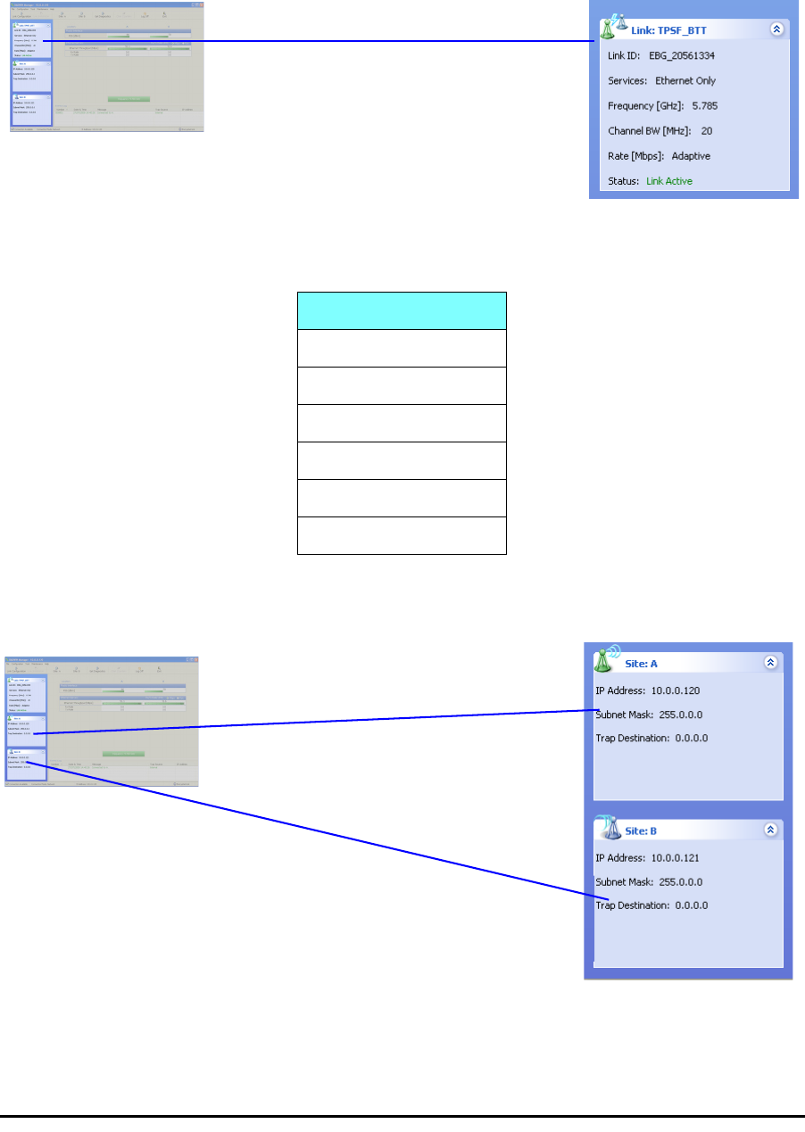
Elements of the RADWIN Manager Main Window
Link details pane
The Link details pane on the left is split into three sections. The top section
summarizes information about the link:
The two lower panels show basic link site details:
Table 5-3: Link Details
Item
Link ID
Services selected
Frequency
Channel bandwidth
Rate
Link status
Elements of the RADWIN Manager Main Window Chapter 5
RADWIN 1000/2000 User Manual Version 2.5p-4 5-7
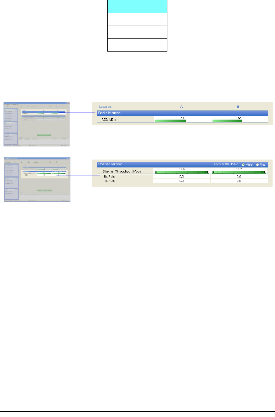
Monitor pane
he monitor pane, is the main source of real time information about link per-
formance at both link sites. It includes the following panes (top to bottom):
• Radio Interface, Received Signal Strength (RSS) in dBm
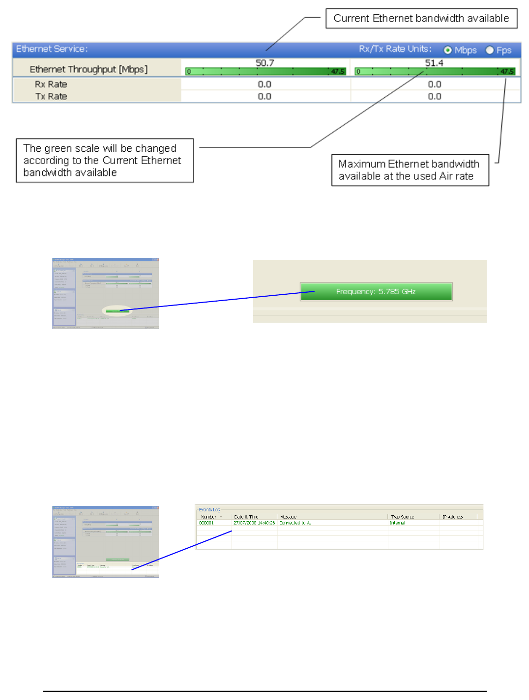
• Ethernet Service:
• Ethernet Throughput: The numbers are the current calculated
throughputs at each site. The colored bars (with numbers) indi-
cate the maximum possible throughput having regard for air
conditions.
• Rx and Tx Rates: Actual Ethernet traffic received and transmit-
ted rates per site, in Mbps of Fbps.
Table 5-4: Link site details, Site A and Site B
Item
IP Address
Subnet Mask
Trap Desalination
Elements of the RADWIN Manager Main Window Chapter 5
RADWIN 1000/2000 User Manual Version 2.5p-4 5-8
Figure 5-2: Ethernet Bandwidth Indication
• Frequency box: It shows the link frequency. The color of the box
indicates the status
•Green is an active link
•Red is an inactive link
•Magenta shows an authentication or compatibility problem
•Brown shows severe compatibility problem
Events Log
The Events Log, stores alarms generated from both sides of the link and is
detailed in chapter 7, The Events Log.
Elements of the RADWIN Manager Main Window Chapter 5
RADWIN 1000/2000 User Manual Version 2.5p-4 5-9
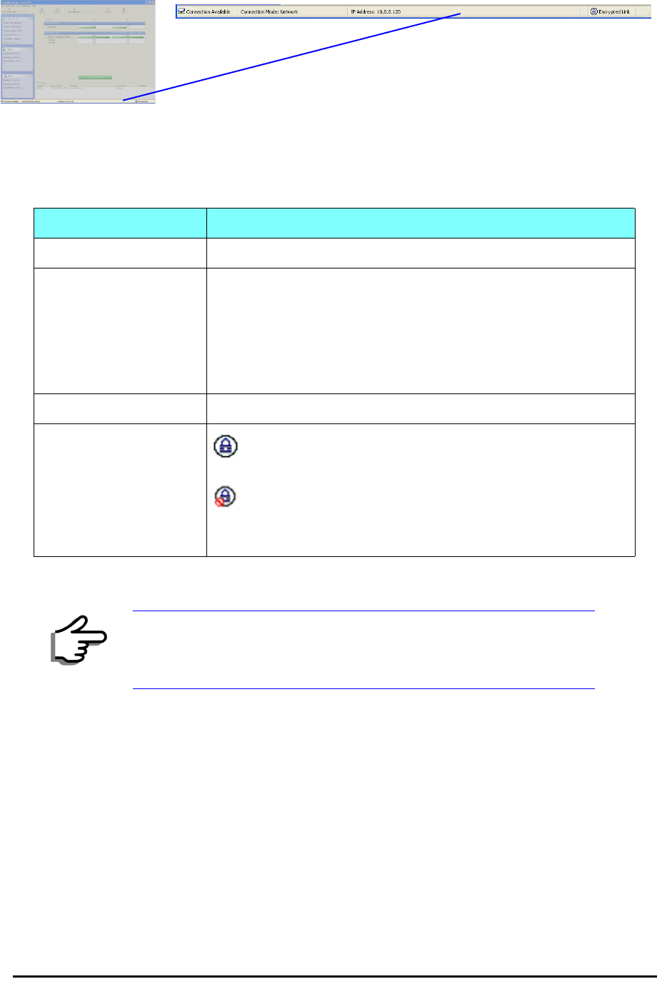
Status Bar
The Status bar, displays the following icons:
Table 5-5: Status bar indicators
Icon or Label Purpose
Connectivity Shows if RADWIN Manager is communicating with the ODU.
Connection available
Connection mode to the ODU
• Over-the-Air connection - using the IP address of the
remote unit.
• Local connection - direct connection to the IDU without
using an IP address.
• Network connection - through a LAN
IP Address Login IP address
Encryption indicator
Normally encrypted link
Link password validation failed. The link is encrypted with
default keys. Service and configuration are unavailable. Change
the link password.
Note
There are several “floating” icons, which appear under specific
conditions
Configuring the Link: Overview Chapter 5
RADWIN 1000/2000 User Manual Version 2.5p-4 5-10
Configuring the Link: Overview
The Configuration Wizard has seven steps as shown in table 5-6 below.
Table 5-6: Link Configuration Wizard
1Wizard welcome
2
System parameters
•Link ID
• Site details
3Channel settings
4Tx power settings
5Services
6Wizard summary and
completion
Configuring the Link: Step 1, Start the Wizard Chapter 5
RADWIN 1000/2000 User Manual Version 2.5p-4 5-11
Since configuration functionality is included in the installation, we will briefly
review the main steps and for most part offer references to the correspond-
ing installation step.
Configuring the Link: Step 1, Start the Wizard
In the tool bar of the RADWIN Manager main window, click the Link Con-
figuration button. The Link Configuration button is only accessible on a
fully installed link as set out in chapter 4.
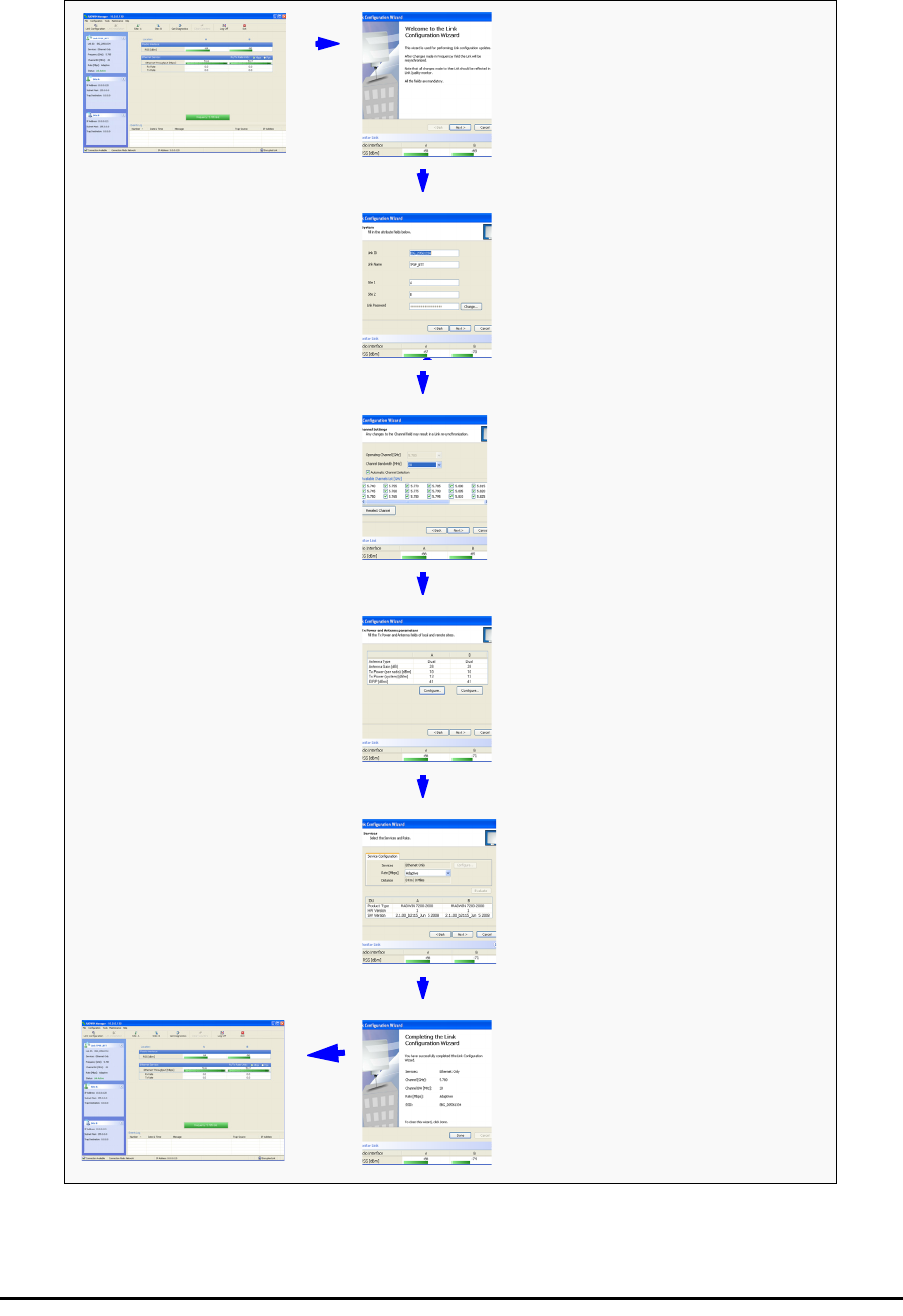
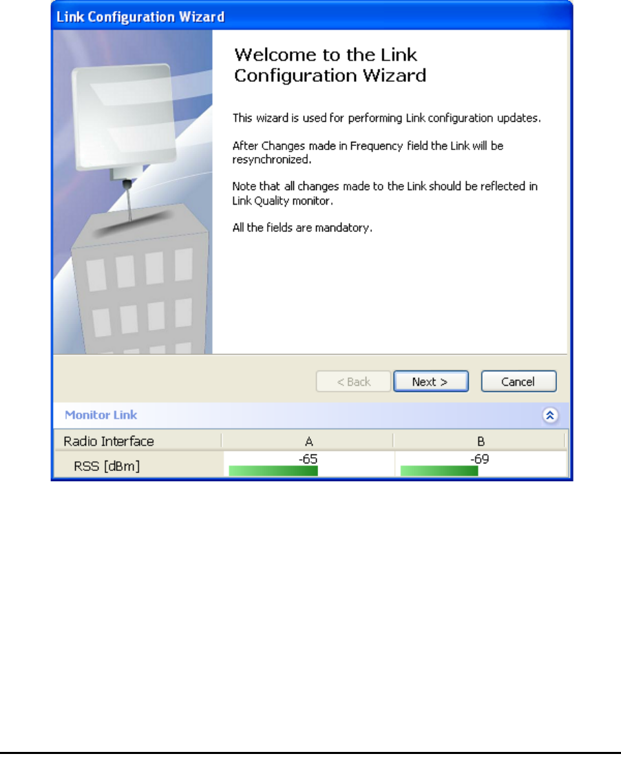
The Configuration Wizard opens:
Figure 5-3: Link Configuration Wizard
Click Next to proceed with the configuration procedure.
Configuring the Link: Step 2, System Parameters
The System dialog box opens:
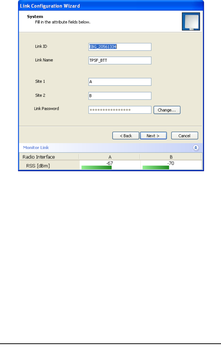
Configuring the Link: Step 3, Channel Settings Chapter 5
RADWIN 1000/2000 User Manual Version 2.5p-4 5-12
Figure 5-4: Configuration Wizard, System dialog box
The System attributes may be edited and the Link Password may be
changed exactly as in the corresponding Link Installation step on page 4-
14.
Click Next to continue.
Configuring the Link: Step 3, Channel Settings
Configuring the Channel Settings follows the same pattern as the Installa-
tion procedure:
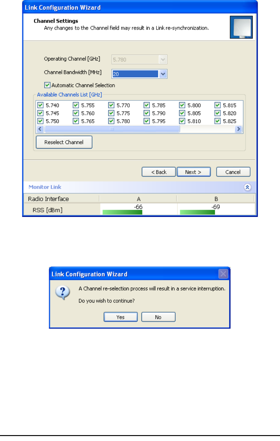
Configuring the Link: Step 3, Channel Settings Chapter 5
RADWIN 1000/2000 User Manual Version 2.5p-4 5-13
Figure 5-5: Channel Settings dialog box - Automatic Channel Selection
Notice that the operating channel is grayed out. If you use the Reselect
Channel button, to change it, you will be asked for confirmation:
If you accept, then the system will search for the best operating channel:
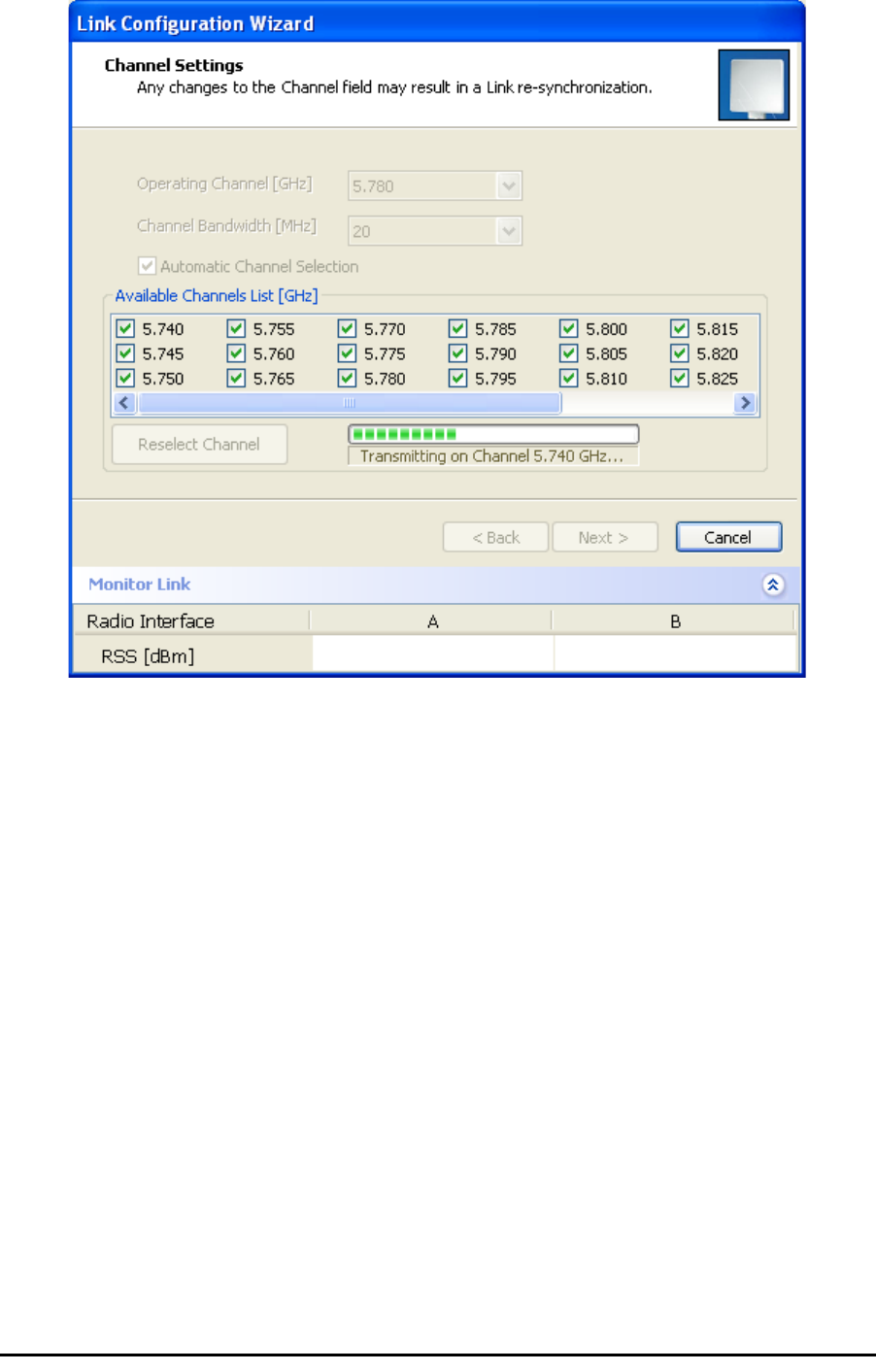
Configuring the Link: Step 3, Channel Settings Chapter 5
RADWIN 1000/2000 User Manual Version 2.5p-4 5-14
Figure 5-6: Searching for the best operating channel
The link will return to the status of figure 5-5 above with a possible
change to the operating channel.
If you work without automatic channel selection, the Channel Settings win-
dow looks like this:
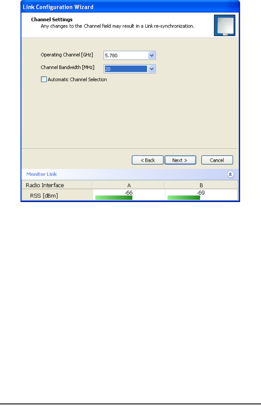
Configuring the Link: Step 3, Channel Settings Chapter 5
RADWIN 1000/2000 User Manual Version 2.5p-4 5-15
Figure 5-7: Channel Settings without automatic channel selection
If you click the Operating Channel drop-down list, the following window
appears:
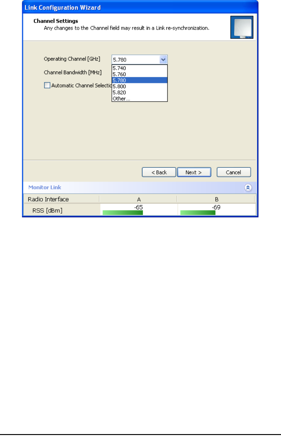
Configuring the Link: Step 3, Channel Settings Chapter 5
RADWIN 1000/2000 User Manual Version 2.5p-4 5-16
Figure 5-8: Channel frequency options
Selecting one of the frequencies presented returns you to the status of
figure 5-7 with the appropriate change. If you choose Other..., the follow-
ing window opens:
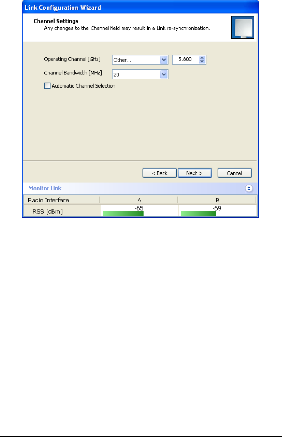
Configuring the Link: Step 3, Channel Settings Chapter 5
RADWIN 1000/2000 User Manual Version 2.5p-4 5-17
Figure 5-9: Choosing an “Other” Operating Channel frequency
The right hand drop-down list (showing 5.800) allows you to fine-tune the
frequency in increments of ±5MHz within a range of 5.740 - 5.835 GHz.
When you have completed making your choice, click Next to continue.
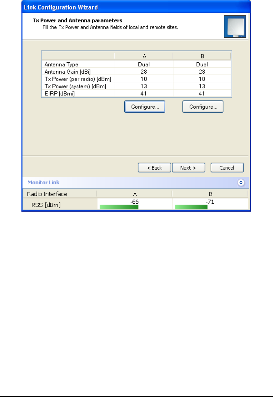
Configuring the Link: Step 4, Tx Power and Antenna Settings Chapter 5
RADWIN 1000/2000 User Manual Version 2.5p-4 5-18
Configuring the Link: Step 4, Tx Power and Antenna
Settings
.
Figure 5-10: Transmission Power and Antenna Parameters
If you chose to configure either antenna, you are presented with the follow-
ing window:
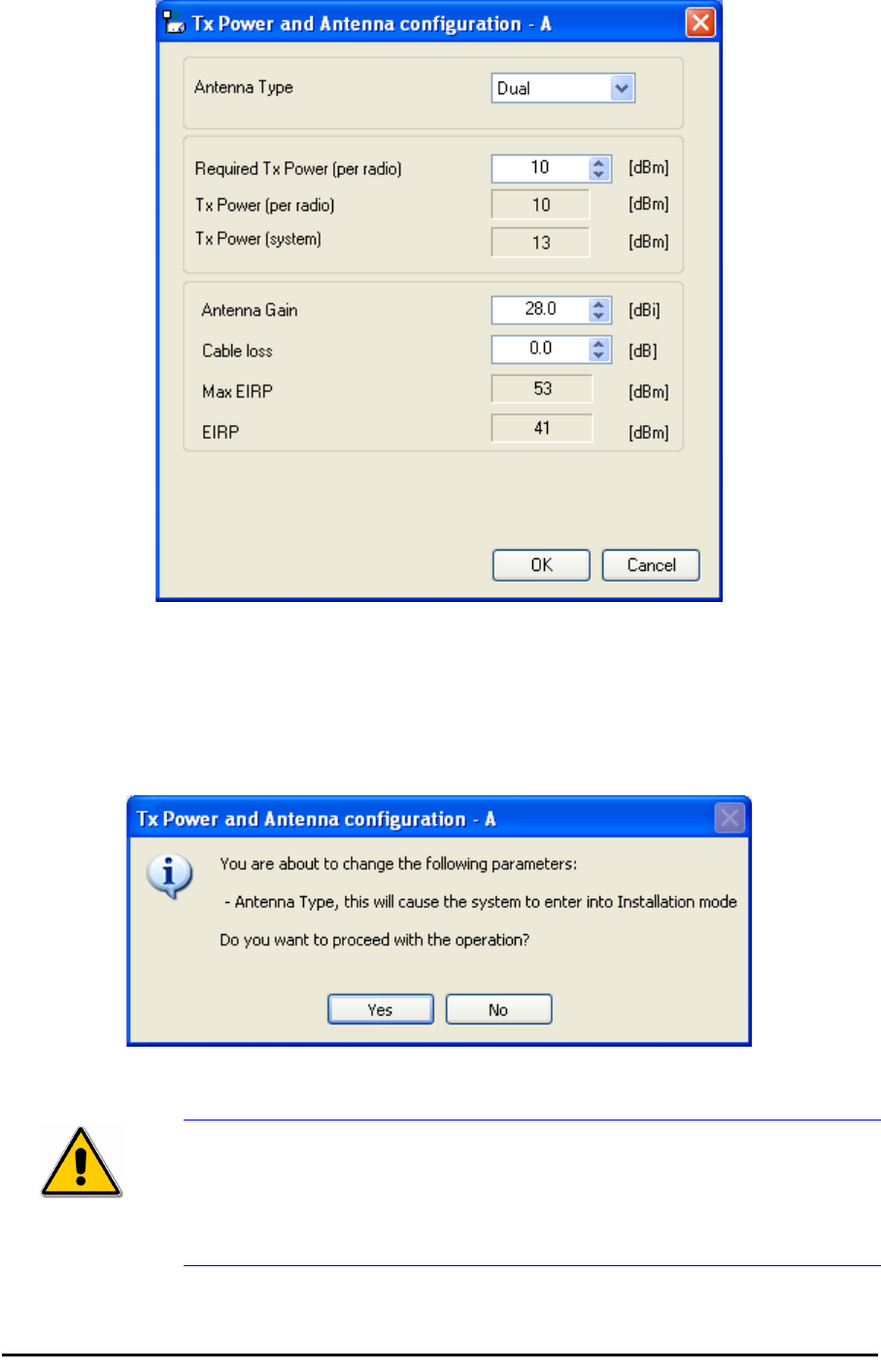
Configuring the Link: Step 4, Tx Power and Antenna Settings Chapter 5
RADWIN 1000/2000 User Manual Version 2.5p-4 5-19
Figure 5-11: Antenna configuration dialog with opened type selection
So far, the procedure duplicates the corresponding Installation process on.
If you choose a different antenna type and click OK, you will receive the fol-
lowing cautionary message:
Caution
In this context, entering Installation mode causes a service break until it is
restored by running the Installation wizard.
If you are uncertain, do not do this without expert technical
assistance.
Configuring the Link: Step 5, Services Chapter 5
RADWIN 1000/2000 User Manual Version 2.5p-4 5-20
You may also change the Required Tx Power, Antenna Gain and Cable Loss.
The procedure is the same as that set out in the Installation procedure on
page 4-23.
When you have completed making your choice, proceed to the Services
window.
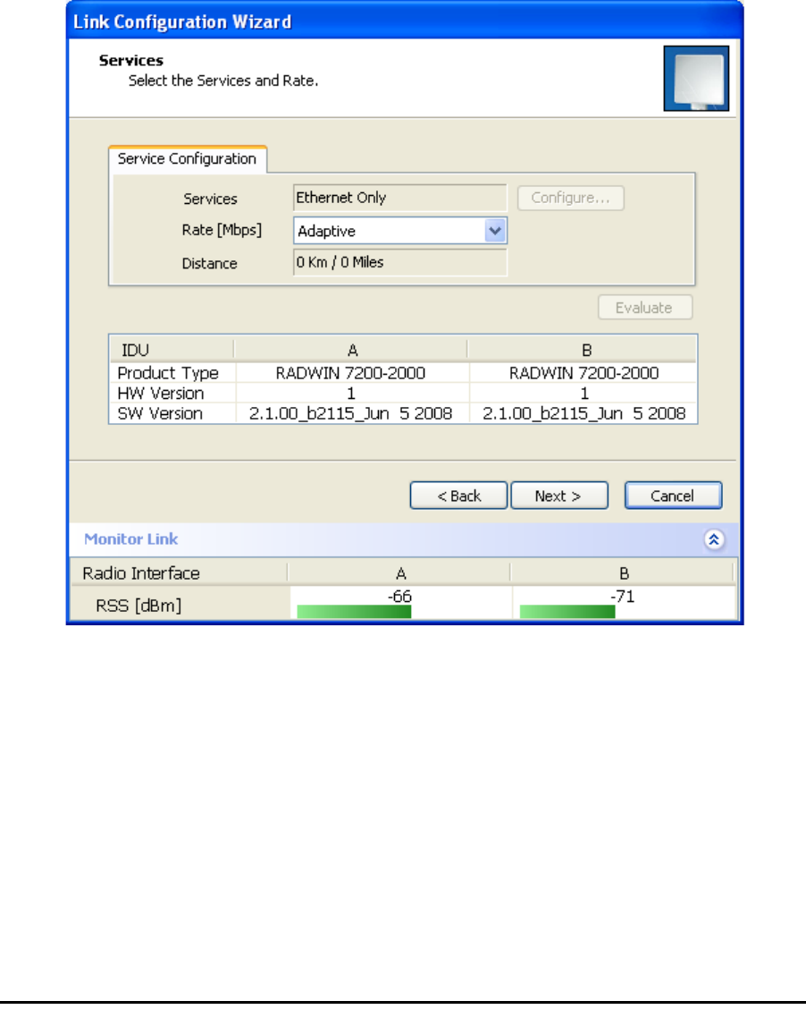
Configuring the Link: Step 5, Services
Here is the services dialog:
.
Figure 5-12: Services and Rates dialog
To choose Services, see the corresponding Installation procedure on
page 5-20.
Click Next to continue.
Configuring the Link: Step 6, Configuration Summary and Exit Chapter 5
RADWIN 1000/2000 User Manual Version 2.5p-4 5-21
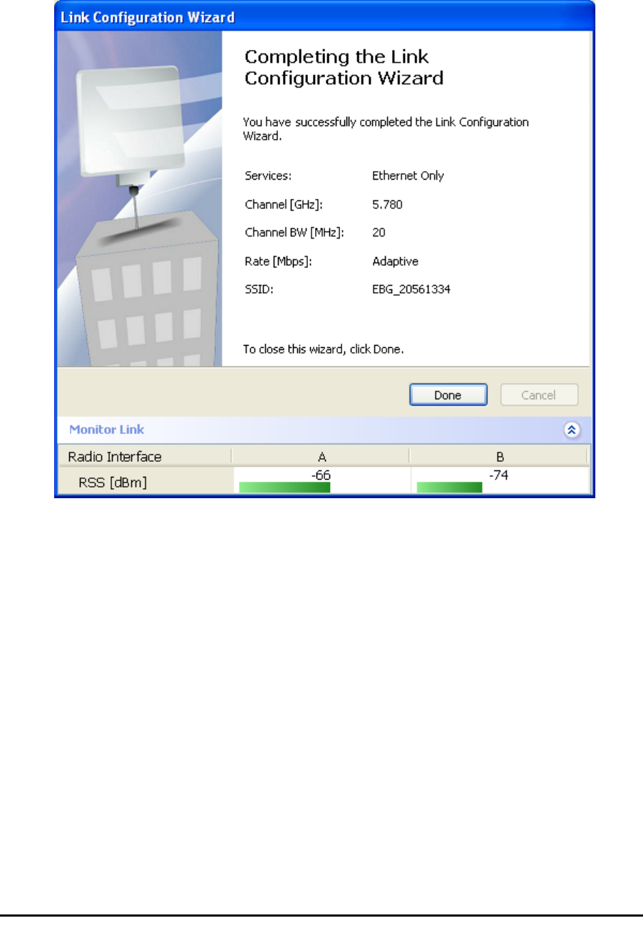
Configuring the Link: Step 6, Configuration Summary and
Exit
Figure 5-13: Configuration Wizard Exit Summary
Click Done to return to the main window.
The main window now reflects the configuration:
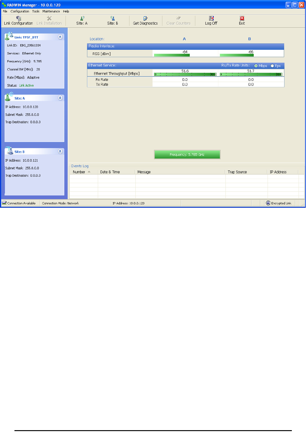
Configuring the Link: Step 6, Configuration Summary and Exit Chapter 5
RADWIN 1000/2000 User Manual Version 2.5p-4 5-22
Figure 5-14: Main window of the manager after configuration